US8518087B2 - Method and apparatus for minimally invasive insertion of intervertebral implants - Google Patents
Method and apparatus for minimally invasive insertion of intervertebral implantsDownload PDFInfo
- Publication number
- US8518087B2 US8518087B2US13/416,889US201213416889AUS8518087B2US 8518087 B2US8518087 B2US 8518087B2US 201213416889 AUS201213416889 AUS 201213416889AUS 8518087 B2US8518087 B2US 8518087B2
- Authority
- US
- United States
- Prior art keywords
- dilator tube
- dilator
- implant
- access cannula
- distal
- Prior art date
- Legal status (The legal status is an assumption and is not a legal conclusion. Google has not performed a legal analysis and makes no representation as to the accuracy of the status listed.)
- Active, expires
Links
- 0CCCCC1C*C(C)CC1Chemical compoundCCCCC1C*C(C)CC10.000description1
Images


Classifications
- A—HUMAN NECESSITIES
- A61—MEDICAL OR VETERINARY SCIENCE; HYGIENE
- A61B—DIAGNOSIS; SURGERY; IDENTIFICATION
- A61B17/00—Surgical instruments, devices or methods
- A61B17/34—Trocars; Puncturing needles
- A61B17/3417—Details of tips or shafts, e.g. grooves, expandable, bendable; Multiple coaxial sliding cannulas, e.g. for dilating
- A61B17/3421—Cannulas
- A61B17/3439—Cannulas with means for changing the inner diameter of the cannula, e.g. expandable
- A—HUMAN NECESSITIES
- A61—MEDICAL OR VETERINARY SCIENCE; HYGIENE
- A61B—DIAGNOSIS; SURGERY; IDENTIFICATION
- A61B17/00—Surgical instruments, devices or methods
- A61B17/34—Trocars; Puncturing needles
- A61B17/3417—Details of tips or shafts, e.g. grooves, expandable, bendable; Multiple coaxial sliding cannulas, e.g. for dilating
- A61B17/3421—Cannulas
- A—HUMAN NECESSITIES
- A61—MEDICAL OR VETERINARY SCIENCE; HYGIENE
- A61B—DIAGNOSIS; SURGERY; IDENTIFICATION
- A61B17/00—Surgical instruments, devices or methods
- A61B17/34—Trocars; Puncturing needles
- A61B17/3468—Trocars; Puncturing needles for implanting or removing devices, e.g. prostheses, implants, seeds, wires
- A—HUMAN NECESSITIES
- A61—MEDICAL OR VETERINARY SCIENCE; HYGIENE
- A61B—DIAGNOSIS; SURGERY; IDENTIFICATION
- A61B17/00—Surgical instruments, devices or methods
- A61B17/56—Surgical instruments or methods for treatment of bones or joints; Devices specially adapted therefor
- A61B17/58—Surgical instruments or methods for treatment of bones or joints; Devices specially adapted therefor for osteosynthesis, e.g. bone plates, screws or setting implements
- A61B17/88—Osteosynthesis instruments; Methods or means for implanting or extracting internal or external fixation devices
- A61B17/885—Tools for expanding or compacting bones or discs or cavities therein
- A—HUMAN NECESSITIES
- A61—MEDICAL OR VETERINARY SCIENCE; HYGIENE
- A61B—DIAGNOSIS; SURGERY; IDENTIFICATION
- A61B18/00—Surgical instruments, devices or methods for transferring non-mechanical forms of energy to or from the body
- A—HUMAN NECESSITIES
- A61—MEDICAL OR VETERINARY SCIENCE; HYGIENE
- A61B—DIAGNOSIS; SURGERY; IDENTIFICATION
- A61B18/00—Surgical instruments, devices or methods for transferring non-mechanical forms of energy to or from the body
- A61B18/04—Surgical instruments, devices or methods for transferring non-mechanical forms of energy to or from the body by heating
- A61B18/12—Surgical instruments, devices or methods for transferring non-mechanical forms of energy to or from the body by heating by passing a current through the tissue to be heated, e.g. high-frequency current
- A61B18/14—Probes or electrodes therefor
- A61B18/1487—Trocar-like, i.e. devices producing an enlarged transcutaneous opening
- A—HUMAN NECESSITIES
- A61—MEDICAL OR VETERINARY SCIENCE; HYGIENE
- A61B—DIAGNOSIS; SURGERY; IDENTIFICATION
- A61B5/00—Measuring for diagnostic purposes; Identification of persons
- A61B5/24—Detecting, measuring or recording bioelectric or biomagnetic signals of the body or parts thereof
- A—HUMAN NECESSITIES
- A61—MEDICAL OR VETERINARY SCIENCE; HYGIENE
- A61B—DIAGNOSIS; SURGERY; IDENTIFICATION
- A61B5/00—Measuring for diagnostic purposes; Identification of persons
- A61B5/48—Other medical applications
- A61B5/4887—Locating particular structures in or on the body
- A61B5/4893—Nerves
- A—HUMAN NECESSITIES
- A61—MEDICAL OR VETERINARY SCIENCE; HYGIENE
- A61F—FILTERS IMPLANTABLE INTO BLOOD VESSELS; PROSTHESES; DEVICES PROVIDING PATENCY TO, OR PREVENTING COLLAPSING OF, TUBULAR STRUCTURES OF THE BODY, e.g. STENTS; ORTHOPAEDIC, NURSING OR CONTRACEPTIVE DEVICES; FOMENTATION; TREATMENT OR PROTECTION OF EYES OR EARS; BANDAGES, DRESSINGS OR ABSORBENT PADS; FIRST-AID KITS
- A61F2/00—Filters implantable into blood vessels; Prostheses, i.e. artificial substitutes or replacements for parts of the body; Appliances for connecting them with the body; Devices providing patency to, or preventing collapsing of, tubular structures of the body, e.g. stents
- A61F2/02—Prostheses implantable into the body
- A61F2/30—Joints
- A61F2/44—Joints for the spine, e.g. vertebrae, spinal discs
- A61F2/442—Intervertebral or spinal discs, e.g. resilient
- A—HUMAN NECESSITIES
- A61—MEDICAL OR VETERINARY SCIENCE; HYGIENE
- A61F—FILTERS IMPLANTABLE INTO BLOOD VESSELS; PROSTHESES; DEVICES PROVIDING PATENCY TO, OR PREVENTING COLLAPSING OF, TUBULAR STRUCTURES OF THE BODY, e.g. STENTS; ORTHOPAEDIC, NURSING OR CONTRACEPTIVE DEVICES; FOMENTATION; TREATMENT OR PROTECTION OF EYES OR EARS; BANDAGES, DRESSINGS OR ABSORBENT PADS; FIRST-AID KITS
- A61F2/00—Filters implantable into blood vessels; Prostheses, i.e. artificial substitutes or replacements for parts of the body; Appliances for connecting them with the body; Devices providing patency to, or preventing collapsing of, tubular structures of the body, e.g. stents
- A61F2/02—Prostheses implantable into the body
- A61F2/30—Joints
- A61F2/44—Joints for the spine, e.g. vertebrae, spinal discs
- A61F2/4455—Joints for the spine, e.g. vertebrae, spinal discs for the fusion of spinal bodies, e.g. intervertebral fusion of adjacent spinal bodies, e.g. fusion cages
- A61F2/447—Joints for the spine, e.g. vertebrae, spinal discs for the fusion of spinal bodies, e.g. intervertebral fusion of adjacent spinal bodies, e.g. fusion cages substantially parallelepipedal, e.g. having a rectangular or trapezoidal cross-section
- A—HUMAN NECESSITIES
- A61—MEDICAL OR VETERINARY SCIENCE; HYGIENE
- A61F—FILTERS IMPLANTABLE INTO BLOOD VESSELS; PROSTHESES; DEVICES PROVIDING PATENCY TO, OR PREVENTING COLLAPSING OF, TUBULAR STRUCTURES OF THE BODY, e.g. STENTS; ORTHOPAEDIC, NURSING OR CONTRACEPTIVE DEVICES; FOMENTATION; TREATMENT OR PROTECTION OF EYES OR EARS; BANDAGES, DRESSINGS OR ABSORBENT PADS; FIRST-AID KITS
- A61F2/00—Filters implantable into blood vessels; Prostheses, i.e. artificial substitutes or replacements for parts of the body; Appliances for connecting them with the body; Devices providing patency to, or preventing collapsing of, tubular structures of the body, e.g. stents
- A61F2/02—Prostheses implantable into the body
- A61F2/30—Joints
- A61F2/46—Special tools for implanting artificial joints
- A61F2/4603—Special tools for implanting artificial joints for insertion or extraction of endoprosthetic joints or of accessories thereof
- A61F2/4611—Special tools for implanting artificial joints for insertion or extraction of endoprosthetic joints or of accessories thereof of spinal prostheses
- A—HUMAN NECESSITIES
- A61—MEDICAL OR VETERINARY SCIENCE; HYGIENE
- A61B—DIAGNOSIS; SURGERY; IDENTIFICATION
- A61B17/00—Surgical instruments, devices or methods
- A61B17/00234—Surgical instruments, devices or methods for minimally invasive surgery
- A61B2017/00238—Type of minimally invasive operation
- A61B2017/00261—Discectomy
- A—HUMAN NECESSITIES
- A61—MEDICAL OR VETERINARY SCIENCE; HYGIENE
- A61B—DIAGNOSIS; SURGERY; IDENTIFICATION
- A61B17/00—Surgical instruments, devices or methods
- A61B2017/00477—Coupling
- A—HUMAN NECESSITIES
- A61—MEDICAL OR VETERINARY SCIENCE; HYGIENE
- A61B—DIAGNOSIS; SURGERY; IDENTIFICATION
- A61B17/00—Surgical instruments, devices or methods
- A61B17/34—Trocars; Puncturing needles
- A61B17/3417—Details of tips or shafts, e.g. grooves, expandable, bendable; Multiple coaxial sliding cannulas, e.g. for dilating
- A61B17/3421—Cannulas
- A61B2017/3445—Cannulas used as instrument channel for multiple instruments
- A—HUMAN NECESSITIES
- A61—MEDICAL OR VETERINARY SCIENCE; HYGIENE
- A61B—DIAGNOSIS; SURGERY; IDENTIFICATION
- A61B18/00—Surgical instruments, devices or methods for transferring non-mechanical forms of energy to or from the body
- A61B2018/00315—Surgical instruments, devices or methods for transferring non-mechanical forms of energy to or from the body for treatment of particular body parts
- A61B2018/00339—Spine, e.g. intervertebral disc
- A—HUMAN NECESSITIES
- A61—MEDICAL OR VETERINARY SCIENCE; HYGIENE
- A61B—DIAGNOSIS; SURGERY; IDENTIFICATION
- A61B18/00—Surgical instruments, devices or methods for transferring non-mechanical forms of energy to or from the body
- A61B2018/00571—Surgical instruments, devices or methods for transferring non-mechanical forms of energy to or from the body for achieving a particular surgical effect
- A61B2018/00601—Cutting
- A—HUMAN NECESSITIES
- A61—MEDICAL OR VETERINARY SCIENCE; HYGIENE
- A61F—FILTERS IMPLANTABLE INTO BLOOD VESSELS; PROSTHESES; DEVICES PROVIDING PATENCY TO, OR PREVENTING COLLAPSING OF, TUBULAR STRUCTURES OF THE BODY, e.g. STENTS; ORTHOPAEDIC, NURSING OR CONTRACEPTIVE DEVICES; FOMENTATION; TREATMENT OR PROTECTION OF EYES OR EARS; BANDAGES, DRESSINGS OR ABSORBENT PADS; FIRST-AID KITS
- A61F2/00—Filters implantable into blood vessels; Prostheses, i.e. artificial substitutes or replacements for parts of the body; Appliances for connecting them with the body; Devices providing patency to, or preventing collapsing of, tubular structures of the body, e.g. stents
- A61F2/02—Prostheses implantable into the body
- A61F2/30—Joints
- A61F2/44—Joints for the spine, e.g. vertebrae, spinal discs
- A—HUMAN NECESSITIES
- A61—MEDICAL OR VETERINARY SCIENCE; HYGIENE
- A61F—FILTERS IMPLANTABLE INTO BLOOD VESSELS; PROSTHESES; DEVICES PROVIDING PATENCY TO, OR PREVENTING COLLAPSING OF, TUBULAR STRUCTURES OF THE BODY, e.g. STENTS; ORTHOPAEDIC, NURSING OR CONTRACEPTIVE DEVICES; FOMENTATION; TREATMENT OR PROTECTION OF EYES OR EARS; BANDAGES, DRESSINGS OR ABSORBENT PADS; FIRST-AID KITS
- A61F2/00—Filters implantable into blood vessels; Prostheses, i.e. artificial substitutes or replacements for parts of the body; Appliances for connecting them with the body; Devices providing patency to, or preventing collapsing of, tubular structures of the body, e.g. stents
- A61F2/02—Prostheses implantable into the body
- A61F2/30—Joints
- A61F2002/30001—Additional features of subject-matter classified in A61F2/28, A61F2/30 and subgroups thereof
- A61F2002/30108—Shapes
- A61F2002/30199—Three-dimensional shapes
- A61F2002/30205—Three-dimensional shapes conical
- A61F2002/30207—Double convex cones, i.e. element having two convex cones, one at each of its opposite ends
- A—HUMAN NECESSITIES
- A61—MEDICAL OR VETERINARY SCIENCE; HYGIENE
- A61F—FILTERS IMPLANTABLE INTO BLOOD VESSELS; PROSTHESES; DEVICES PROVIDING PATENCY TO, OR PREVENTING COLLAPSING OF, TUBULAR STRUCTURES OF THE BODY, e.g. STENTS; ORTHOPAEDIC, NURSING OR CONTRACEPTIVE DEVICES; FOMENTATION; TREATMENT OR PROTECTION OF EYES OR EARS; BANDAGES, DRESSINGS OR ABSORBENT PADS; FIRST-AID KITS
- A61F2/00—Filters implantable into blood vessels; Prostheses, i.e. artificial substitutes or replacements for parts of the body; Appliances for connecting them with the body; Devices providing patency to, or preventing collapsing of, tubular structures of the body, e.g. stents
- A61F2/02—Prostheses implantable into the body
- A61F2/30—Joints
- A61F2002/30001—Additional features of subject-matter classified in A61F2/28, A61F2/30 and subgroups thereof
- A61F2002/30108—Shapes
- A61F2002/30199—Three-dimensional shapes
- A61F2002/30205—Three-dimensional shapes conical
- A61F2002/3021—Three-dimensional shapes conical frustoconical
- A—HUMAN NECESSITIES
- A61—MEDICAL OR VETERINARY SCIENCE; HYGIENE
- A61F—FILTERS IMPLANTABLE INTO BLOOD VESSELS; PROSTHESES; DEVICES PROVIDING PATENCY TO, OR PREVENTING COLLAPSING OF, TUBULAR STRUCTURES OF THE BODY, e.g. STENTS; ORTHOPAEDIC, NURSING OR CONTRACEPTIVE DEVICES; FOMENTATION; TREATMENT OR PROTECTION OF EYES OR EARS; BANDAGES, DRESSINGS OR ABSORBENT PADS; FIRST-AID KITS
- A61F2/00—Filters implantable into blood vessels; Prostheses, i.e. artificial substitutes or replacements for parts of the body; Appliances for connecting them with the body; Devices providing patency to, or preventing collapsing of, tubular structures of the body, e.g. stents
- A61F2/02—Prostheses implantable into the body
- A61F2/30—Joints
- A61F2002/30001—Additional features of subject-matter classified in A61F2/28, A61F2/30 and subgroups thereof
- A61F2002/30108—Shapes
- A61F2002/30199—Three-dimensional shapes
- A61F2002/30261—Three-dimensional shapes parallelepipedal
- A61F2002/30265—Flat parallelepipeds
- A—HUMAN NECESSITIES
- A61—MEDICAL OR VETERINARY SCIENCE; HYGIENE
- A61F—FILTERS IMPLANTABLE INTO BLOOD VESSELS; PROSTHESES; DEVICES PROVIDING PATENCY TO, OR PREVENTING COLLAPSING OF, TUBULAR STRUCTURES OF THE BODY, e.g. STENTS; ORTHOPAEDIC, NURSING OR CONTRACEPTIVE DEVICES; FOMENTATION; TREATMENT OR PROTECTION OF EYES OR EARS; BANDAGES, DRESSINGS OR ABSORBENT PADS; FIRST-AID KITS
- A61F2/00—Filters implantable into blood vessels; Prostheses, i.e. artificial substitutes or replacements for parts of the body; Appliances for connecting them with the body; Devices providing patency to, or preventing collapsing of, tubular structures of the body, e.g. stents
- A61F2/02—Prostheses implantable into the body
- A61F2/30—Joints
- A61F2002/30001—Additional features of subject-matter classified in A61F2/28, A61F2/30 and subgroups thereof
- A61F2002/30108—Shapes
- A61F2002/30199—Three-dimensional shapes
- A61F2002/30261—Three-dimensional shapes parallelepipedal
- A61F2002/30266—Three-dimensional shapes parallelepipedal wedge-shaped parallelepipeds
- A—HUMAN NECESSITIES
- A61—MEDICAL OR VETERINARY SCIENCE; HYGIENE
- A61F—FILTERS IMPLANTABLE INTO BLOOD VESSELS; PROSTHESES; DEVICES PROVIDING PATENCY TO, OR PREVENTING COLLAPSING OF, TUBULAR STRUCTURES OF THE BODY, e.g. STENTS; ORTHOPAEDIC, NURSING OR CONTRACEPTIVE DEVICES; FOMENTATION; TREATMENT OR PROTECTION OF EYES OR EARS; BANDAGES, DRESSINGS OR ABSORBENT PADS; FIRST-AID KITS
- A61F2/00—Filters implantable into blood vessels; Prostheses, i.e. artificial substitutes or replacements for parts of the body; Appliances for connecting them with the body; Devices providing patency to, or preventing collapsing of, tubular structures of the body, e.g. stents
- A61F2/02—Prostheses implantable into the body
- A61F2/30—Joints
- A61F2002/30001—Additional features of subject-matter classified in A61F2/28, A61F2/30 and subgroups thereof
- A61F2002/30316—The prosthesis having different structural features at different locations within the same prosthesis; Connections between prosthetic parts; Special structural features of bone or joint prostheses not otherwise provided for
- A61F2002/30329—Connections or couplings between prosthetic parts, e.g. between modular parts; Connecting elements
- A61F2002/30331—Connections or couplings between prosthetic parts, e.g. between modular parts; Connecting elements made by longitudinally pushing a protrusion into a complementarily-shaped recess, e.g. held by friction fit
- A61F2002/30362—Connections or couplings between prosthetic parts, e.g. between modular parts; Connecting elements made by longitudinally pushing a protrusion into a complementarily-shaped recess, e.g. held by friction fit with possibility of relative movement between the protrusion and the recess
- A61F2002/3037—Translation along the common longitudinal axis, e.g. piston
- A61F2002/30372—Translation along the common longitudinal axis, e.g. piston with additional means for limiting said translation
- A—HUMAN NECESSITIES
- A61—MEDICAL OR VETERINARY SCIENCE; HYGIENE
- A61F—FILTERS IMPLANTABLE INTO BLOOD VESSELS; PROSTHESES; DEVICES PROVIDING PATENCY TO, OR PREVENTING COLLAPSING OF, TUBULAR STRUCTURES OF THE BODY, e.g. STENTS; ORTHOPAEDIC, NURSING OR CONTRACEPTIVE DEVICES; FOMENTATION; TREATMENT OR PROTECTION OF EYES OR EARS; BANDAGES, DRESSINGS OR ABSORBENT PADS; FIRST-AID KITS
- A61F2/00—Filters implantable into blood vessels; Prostheses, i.e. artificial substitutes or replacements for parts of the body; Appliances for connecting them with the body; Devices providing patency to, or preventing collapsing of, tubular structures of the body, e.g. stents
- A61F2/02—Prostheses implantable into the body
- A61F2/30—Joints
- A61F2002/30001—Additional features of subject-matter classified in A61F2/28, A61F2/30 and subgroups thereof
- A61F2002/30316—The prosthesis having different structural features at different locations within the same prosthesis; Connections between prosthetic parts; Special structural features of bone or joint prostheses not otherwise provided for
- A61F2002/30329—Connections or couplings between prosthetic parts, e.g. between modular parts; Connecting elements
- A61F2002/30331—Connections or couplings between prosthetic parts, e.g. between modular parts; Connecting elements made by longitudinally pushing a protrusion into a complementarily-shaped recess, e.g. held by friction fit
- A61F2002/30362—Connections or couplings between prosthetic parts, e.g. between modular parts; Connecting elements made by longitudinally pushing a protrusion into a complementarily-shaped recess, e.g. held by friction fit with possibility of relative movement between the protrusion and the recess
- A61F2002/3037—Translation along the common longitudinal axis, e.g. piston
- A61F2002/30373—Translation along the common longitudinal axis, e.g. piston with additional means for preventing said translation
- A—HUMAN NECESSITIES
- A61—MEDICAL OR VETERINARY SCIENCE; HYGIENE
- A61F—FILTERS IMPLANTABLE INTO BLOOD VESSELS; PROSTHESES; DEVICES PROVIDING PATENCY TO, OR PREVENTING COLLAPSING OF, TUBULAR STRUCTURES OF THE BODY, e.g. STENTS; ORTHOPAEDIC, NURSING OR CONTRACEPTIVE DEVICES; FOMENTATION; TREATMENT OR PROTECTION OF EYES OR EARS; BANDAGES, DRESSINGS OR ABSORBENT PADS; FIRST-AID KITS
- A61F2/00—Filters implantable into blood vessels; Prostheses, i.e. artificial substitutes or replacements for parts of the body; Appliances for connecting them with the body; Devices providing patency to, or preventing collapsing of, tubular structures of the body, e.g. stents
- A61F2/02—Prostheses implantable into the body
- A61F2/30—Joints
- A61F2002/30001—Additional features of subject-matter classified in A61F2/28, A61F2/30 and subgroups thereof
- A61F2002/30316—The prosthesis having different structural features at different locations within the same prosthesis; Connections between prosthetic parts; Special structural features of bone or joint prostheses not otherwise provided for
- A61F2002/30329—Connections or couplings between prosthetic parts, e.g. between modular parts; Connecting elements
- A61F2002/30383—Connections or couplings between prosthetic parts, e.g. between modular parts; Connecting elements made by laterally inserting a protrusion, e.g. a rib into a complementarily-shaped groove
- A61F2002/30387—Dovetail connection
- A—HUMAN NECESSITIES
- A61—MEDICAL OR VETERINARY SCIENCE; HYGIENE
- A61F—FILTERS IMPLANTABLE INTO BLOOD VESSELS; PROSTHESES; DEVICES PROVIDING PATENCY TO, OR PREVENTING COLLAPSING OF, TUBULAR STRUCTURES OF THE BODY, e.g. STENTS; ORTHOPAEDIC, NURSING OR CONTRACEPTIVE DEVICES; FOMENTATION; TREATMENT OR PROTECTION OF EYES OR EARS; BANDAGES, DRESSINGS OR ABSORBENT PADS; FIRST-AID KITS
- A61F2/00—Filters implantable into blood vessels; Prostheses, i.e. artificial substitutes or replacements for parts of the body; Appliances for connecting them with the body; Devices providing patency to, or preventing collapsing of, tubular structures of the body, e.g. stents
- A61F2/02—Prostheses implantable into the body
- A61F2/30—Joints
- A61F2002/30001—Additional features of subject-matter classified in A61F2/28, A61F2/30 and subgroups thereof
- A61F2002/30316—The prosthesis having different structural features at different locations within the same prosthesis; Connections between prosthetic parts; Special structural features of bone or joint prostheses not otherwise provided for
- A61F2002/30329—Connections or couplings between prosthetic parts, e.g. between modular parts; Connecting elements
- A61F2002/30405—Connections or couplings between prosthetic parts, e.g. between modular parts; Connecting elements made by screwing complementary threads machined on the parts themselves
- A61F2002/3041—Connections or couplings between prosthetic parts, e.g. between modular parts; Connecting elements made by screwing complementary threads machined on the parts themselves having threaded portions of different pitches
- A—HUMAN NECESSITIES
- A61—MEDICAL OR VETERINARY SCIENCE; HYGIENE
- A61F—FILTERS IMPLANTABLE INTO BLOOD VESSELS; PROSTHESES; DEVICES PROVIDING PATENCY TO, OR PREVENTING COLLAPSING OF, TUBULAR STRUCTURES OF THE BODY, e.g. STENTS; ORTHOPAEDIC, NURSING OR CONTRACEPTIVE DEVICES; FOMENTATION; TREATMENT OR PROTECTION OF EYES OR EARS; BANDAGES, DRESSINGS OR ABSORBENT PADS; FIRST-AID KITS
- A61F2/00—Filters implantable into blood vessels; Prostheses, i.e. artificial substitutes or replacements for parts of the body; Appliances for connecting them with the body; Devices providing patency to, or preventing collapsing of, tubular structures of the body, e.g. stents
- A61F2/02—Prostheses implantable into the body
- A61F2/30—Joints
- A61F2002/30001—Additional features of subject-matter classified in A61F2/28, A61F2/30 and subgroups thereof
- A61F2002/30316—The prosthesis having different structural features at different locations within the same prosthesis; Connections between prosthetic parts; Special structural features of bone or joint prostheses not otherwise provided for
- A61F2002/30329—Connections or couplings between prosthetic parts, e.g. between modular parts; Connecting elements
- A61F2002/30405—Connections or couplings between prosthetic parts, e.g. between modular parts; Connecting elements made by screwing complementary threads machined on the parts themselves
- A61F2002/30411—Connections or couplings between prosthetic parts, e.g. between modular parts; Connecting elements made by screwing complementary threads machined on the parts themselves having two threaded end parts connected by a threaded central part with opposite threads at its opposite ends, i.e. for adjusting the distance between both end parts by rotating the central part
- A—HUMAN NECESSITIES
- A61—MEDICAL OR VETERINARY SCIENCE; HYGIENE
- A61F—FILTERS IMPLANTABLE INTO BLOOD VESSELS; PROSTHESES; DEVICES PROVIDING PATENCY TO, OR PREVENTING COLLAPSING OF, TUBULAR STRUCTURES OF THE BODY, e.g. STENTS; ORTHOPAEDIC, NURSING OR CONTRACEPTIVE DEVICES; FOMENTATION; TREATMENT OR PROTECTION OF EYES OR EARS; BANDAGES, DRESSINGS OR ABSORBENT PADS; FIRST-AID KITS
- A61F2/00—Filters implantable into blood vessels; Prostheses, i.e. artificial substitutes or replacements for parts of the body; Appliances for connecting them with the body; Devices providing patency to, or preventing collapsing of, tubular structures of the body, e.g. stents
- A61F2/02—Prostheses implantable into the body
- A61F2/30—Joints
- A61F2002/30001—Additional features of subject-matter classified in A61F2/28, A61F2/30 and subgroups thereof
- A61F2002/30316—The prosthesis having different structural features at different locations within the same prosthesis; Connections between prosthetic parts; Special structural features of bone or joint prostheses not otherwise provided for
- A61F2002/30329—Connections or couplings between prosthetic parts, e.g. between modular parts; Connecting elements
- A61F2002/30476—Connections or couplings between prosthetic parts, e.g. between modular parts; Connecting elements locked by an additional locking mechanism
- A61F2002/30482—Connections or couplings between prosthetic parts, e.g. between modular parts; Connecting elements locked by an additional locking mechanism using a locking cam
- A—HUMAN NECESSITIES
- A61—MEDICAL OR VETERINARY SCIENCE; HYGIENE
- A61F—FILTERS IMPLANTABLE INTO BLOOD VESSELS; PROSTHESES; DEVICES PROVIDING PATENCY TO, OR PREVENTING COLLAPSING OF, TUBULAR STRUCTURES OF THE BODY, e.g. STENTS; ORTHOPAEDIC, NURSING OR CONTRACEPTIVE DEVICES; FOMENTATION; TREATMENT OR PROTECTION OF EYES OR EARS; BANDAGES, DRESSINGS OR ABSORBENT PADS; FIRST-AID KITS
- A61F2/00—Filters implantable into blood vessels; Prostheses, i.e. artificial substitutes or replacements for parts of the body; Appliances for connecting them with the body; Devices providing patency to, or preventing collapsing of, tubular structures of the body, e.g. stents
- A61F2/02—Prostheses implantable into the body
- A61F2/30—Joints
- A61F2002/30001—Additional features of subject-matter classified in A61F2/28, A61F2/30 and subgroups thereof
- A61F2002/30316—The prosthesis having different structural features at different locations within the same prosthesis; Connections between prosthetic parts; Special structural features of bone or joint prostheses not otherwise provided for
- A61F2002/30329—Connections or couplings between prosthetic parts, e.g. between modular parts; Connecting elements
- A61F2002/30476—Connections or couplings between prosthetic parts, e.g. between modular parts; Connecting elements locked by an additional locking mechanism
- A61F2002/30484—Mechanically expandable devices located on the first prosthetic part for locking into or onto the second prosthetic part
- A—HUMAN NECESSITIES
- A61—MEDICAL OR VETERINARY SCIENCE; HYGIENE
- A61F—FILTERS IMPLANTABLE INTO BLOOD VESSELS; PROSTHESES; DEVICES PROVIDING PATENCY TO, OR PREVENTING COLLAPSING OF, TUBULAR STRUCTURES OF THE BODY, e.g. STENTS; ORTHOPAEDIC, NURSING OR CONTRACEPTIVE DEVICES; FOMENTATION; TREATMENT OR PROTECTION OF EYES OR EARS; BANDAGES, DRESSINGS OR ABSORBENT PADS; FIRST-AID KITS
- A61F2/00—Filters implantable into blood vessels; Prostheses, i.e. artificial substitutes or replacements for parts of the body; Appliances for connecting them with the body; Devices providing patency to, or preventing collapsing of, tubular structures of the body, e.g. stents
- A61F2/02—Prostheses implantable into the body
- A61F2/30—Joints
- A61F2002/30001—Additional features of subject-matter classified in A61F2/28, A61F2/30 and subgroups thereof
- A61F2002/30316—The prosthesis having different structural features at different locations within the same prosthesis; Connections between prosthetic parts; Special structural features of bone or joint prostheses not otherwise provided for
- A61F2002/30329—Connections or couplings between prosthetic parts, e.g. between modular parts; Connecting elements
- A61F2002/30476—Connections or couplings between prosthetic parts, e.g. between modular parts; Connecting elements locked by an additional locking mechanism
- A61F2002/30517—Connections or couplings between prosthetic parts, e.g. between modular parts; Connecting elements locked by an additional locking mechanism using a locking plate
- A—HUMAN NECESSITIES
- A61—MEDICAL OR VETERINARY SCIENCE; HYGIENE
- A61F—FILTERS IMPLANTABLE INTO BLOOD VESSELS; PROSTHESES; DEVICES PROVIDING PATENCY TO, OR PREVENTING COLLAPSING OF, TUBULAR STRUCTURES OF THE BODY, e.g. STENTS; ORTHOPAEDIC, NURSING OR CONTRACEPTIVE DEVICES; FOMENTATION; TREATMENT OR PROTECTION OF EYES OR EARS; BANDAGES, DRESSINGS OR ABSORBENT PADS; FIRST-AID KITS
- A61F2/00—Filters implantable into blood vessels; Prostheses, i.e. artificial substitutes or replacements for parts of the body; Appliances for connecting them with the body; Devices providing patency to, or preventing collapsing of, tubular structures of the body, e.g. stents
- A61F2/02—Prostheses implantable into the body
- A61F2/30—Joints
- A61F2002/30001—Additional features of subject-matter classified in A61F2/28, A61F2/30 and subgroups thereof
- A61F2002/30316—The prosthesis having different structural features at different locations within the same prosthesis; Connections between prosthetic parts; Special structural features of bone or joint prostheses not otherwise provided for
- A61F2002/30329—Connections or couplings between prosthetic parts, e.g. between modular parts; Connecting elements
- A61F2002/30518—Connections or couplings between prosthetic parts, e.g. between modular parts; Connecting elements with possibility of relative movement between the prosthetic parts
- A61F2002/30523—Connections or couplings between prosthetic parts, e.g. between modular parts; Connecting elements with possibility of relative movement between the prosthetic parts by means of meshing gear teeth
- A—HUMAN NECESSITIES
- A61—MEDICAL OR VETERINARY SCIENCE; HYGIENE
- A61F—FILTERS IMPLANTABLE INTO BLOOD VESSELS; PROSTHESES; DEVICES PROVIDING PATENCY TO, OR PREVENTING COLLAPSING OF, TUBULAR STRUCTURES OF THE BODY, e.g. STENTS; ORTHOPAEDIC, NURSING OR CONTRACEPTIVE DEVICES; FOMENTATION; TREATMENT OR PROTECTION OF EYES OR EARS; BANDAGES, DRESSINGS OR ABSORBENT PADS; FIRST-AID KITS
- A61F2/00—Filters implantable into blood vessels; Prostheses, i.e. artificial substitutes or replacements for parts of the body; Appliances for connecting them with the body; Devices providing patency to, or preventing collapsing of, tubular structures of the body, e.g. stents
- A61F2/02—Prostheses implantable into the body
- A61F2/30—Joints
- A61F2002/30001—Additional features of subject-matter classified in A61F2/28, A61F2/30 and subgroups thereof
- A61F2002/30316—The prosthesis having different structural features at different locations within the same prosthesis; Connections between prosthetic parts; Special structural features of bone or joint prostheses not otherwise provided for
- A61F2002/30329—Connections or couplings between prosthetic parts, e.g. between modular parts; Connecting elements
- A61F2002/30518—Connections or couplings between prosthetic parts, e.g. between modular parts; Connecting elements with possibility of relative movement between the prosthetic parts
- A61F2002/30528—Means for limiting said movement
- A—HUMAN NECESSITIES
- A61—MEDICAL OR VETERINARY SCIENCE; HYGIENE
- A61F—FILTERS IMPLANTABLE INTO BLOOD VESSELS; PROSTHESES; DEVICES PROVIDING PATENCY TO, OR PREVENTING COLLAPSING OF, TUBULAR STRUCTURES OF THE BODY, e.g. STENTS; ORTHOPAEDIC, NURSING OR CONTRACEPTIVE DEVICES; FOMENTATION; TREATMENT OR PROTECTION OF EYES OR EARS; BANDAGES, DRESSINGS OR ABSORBENT PADS; FIRST-AID KITS
- A61F2/00—Filters implantable into blood vessels; Prostheses, i.e. artificial substitutes or replacements for parts of the body; Appliances for connecting them with the body; Devices providing patency to, or preventing collapsing of, tubular structures of the body, e.g. stents
- A61F2/02—Prostheses implantable into the body
- A61F2/30—Joints
- A61F2002/30001—Additional features of subject-matter classified in A61F2/28, A61F2/30 and subgroups thereof
- A61F2002/30316—The prosthesis having different structural features at different locations within the same prosthesis; Connections between prosthetic parts; Special structural features of bone or joint prostheses not otherwise provided for
- A61F2002/30535—Special structural features of bone or joint prostheses not otherwise provided for
- A61F2002/30537—Special structural features of bone or joint prostheses not otherwise provided for adjustable
- A61F2002/30538—Special structural features of bone or joint prostheses not otherwise provided for adjustable for adjusting angular orientation
- A—HUMAN NECESSITIES
- A61—MEDICAL OR VETERINARY SCIENCE; HYGIENE
- A61F—FILTERS IMPLANTABLE INTO BLOOD VESSELS; PROSTHESES; DEVICES PROVIDING PATENCY TO, OR PREVENTING COLLAPSING OF, TUBULAR STRUCTURES OF THE BODY, e.g. STENTS; ORTHOPAEDIC, NURSING OR CONTRACEPTIVE DEVICES; FOMENTATION; TREATMENT OR PROTECTION OF EYES OR EARS; BANDAGES, DRESSINGS OR ABSORBENT PADS; FIRST-AID KITS
- A61F2/00—Filters implantable into blood vessels; Prostheses, i.e. artificial substitutes or replacements for parts of the body; Appliances for connecting them with the body; Devices providing patency to, or preventing collapsing of, tubular structures of the body, e.g. stents
- A61F2/02—Prostheses implantable into the body
- A61F2/30—Joints
- A61F2002/30001—Additional features of subject-matter classified in A61F2/28, A61F2/30 and subgroups thereof
- A61F2002/30316—The prosthesis having different structural features at different locations within the same prosthesis; Connections between prosthetic parts; Special structural features of bone or joint prostheses not otherwise provided for
- A61F2002/30535—Special structural features of bone or joint prostheses not otherwise provided for
- A61F2002/30537—Special structural features of bone or joint prostheses not otherwise provided for adjustable
- A61F2002/30556—Special structural features of bone or joint prostheses not otherwise provided for adjustable for adjusting thickness
- A—HUMAN NECESSITIES
- A61—MEDICAL OR VETERINARY SCIENCE; HYGIENE
- A61F—FILTERS IMPLANTABLE INTO BLOOD VESSELS; PROSTHESES; DEVICES PROVIDING PATENCY TO, OR PREVENTING COLLAPSING OF, TUBULAR STRUCTURES OF THE BODY, e.g. STENTS; ORTHOPAEDIC, NURSING OR CONTRACEPTIVE DEVICES; FOMENTATION; TREATMENT OR PROTECTION OF EYES OR EARS; BANDAGES, DRESSINGS OR ABSORBENT PADS; FIRST-AID KITS
- A61F2/00—Filters implantable into blood vessels; Prostheses, i.e. artificial substitutes or replacements for parts of the body; Appliances for connecting them with the body; Devices providing patency to, or preventing collapsing of, tubular structures of the body, e.g. stents
- A61F2/02—Prostheses implantable into the body
- A61F2/30—Joints
- A61F2002/30001—Additional features of subject-matter classified in A61F2/28, A61F2/30 and subgroups thereof
- A61F2002/30316—The prosthesis having different structural features at different locations within the same prosthesis; Connections between prosthetic parts; Special structural features of bone or joint prostheses not otherwise provided for
- A61F2002/30535—Special structural features of bone or joint prostheses not otherwise provided for
- A61F2002/30558—Force-limiting means
- A—HUMAN NECESSITIES
- A61—MEDICAL OR VETERINARY SCIENCE; HYGIENE
- A61F—FILTERS IMPLANTABLE INTO BLOOD VESSELS; PROSTHESES; DEVICES PROVIDING PATENCY TO, OR PREVENTING COLLAPSING OF, TUBULAR STRUCTURES OF THE BODY, e.g. STENTS; ORTHOPAEDIC, NURSING OR CONTRACEPTIVE DEVICES; FOMENTATION; TREATMENT OR PROTECTION OF EYES OR EARS; BANDAGES, DRESSINGS OR ABSORBENT PADS; FIRST-AID KITS
- A61F2/00—Filters implantable into blood vessels; Prostheses, i.e. artificial substitutes or replacements for parts of the body; Appliances for connecting them with the body; Devices providing patency to, or preventing collapsing of, tubular structures of the body, e.g. stents
- A61F2/02—Prostheses implantable into the body
- A61F2/30—Joints
- A61F2002/30001—Additional features of subject-matter classified in A61F2/28, A61F2/30 and subgroups thereof
- A61F2002/30316—The prosthesis having different structural features at different locations within the same prosthesis; Connections between prosthetic parts; Special structural features of bone or joint prostheses not otherwise provided for
- A61F2002/30535—Special structural features of bone or joint prostheses not otherwise provided for
- A61F2002/30561—Special structural features of bone or joint prostheses not otherwise provided for breakable or frangible
- A—HUMAN NECESSITIES
- A61—MEDICAL OR VETERINARY SCIENCE; HYGIENE
- A61F—FILTERS IMPLANTABLE INTO BLOOD VESSELS; PROSTHESES; DEVICES PROVIDING PATENCY TO, OR PREVENTING COLLAPSING OF, TUBULAR STRUCTURES OF THE BODY, e.g. STENTS; ORTHOPAEDIC, NURSING OR CONTRACEPTIVE DEVICES; FOMENTATION; TREATMENT OR PROTECTION OF EYES OR EARS; BANDAGES, DRESSINGS OR ABSORBENT PADS; FIRST-AID KITS
- A61F2/00—Filters implantable into blood vessels; Prostheses, i.e. artificial substitutes or replacements for parts of the body; Appliances for connecting them with the body; Devices providing patency to, or preventing collapsing of, tubular structures of the body, e.g. stents
- A61F2/02—Prostheses implantable into the body
- A61F2/30—Joints
- A61F2002/30001—Additional features of subject-matter classified in A61F2/28, A61F2/30 and subgroups thereof
- A61F2002/30316—The prosthesis having different structural features at different locations within the same prosthesis; Connections between prosthetic parts; Special structural features of bone or joint prostheses not otherwise provided for
- A61F2002/30535—Special structural features of bone or joint prostheses not otherwise provided for
- A61F2002/30579—Special structural features of bone or joint prostheses not otherwise provided for with mechanically expandable devices, e.g. fixation devices
- A—HUMAN NECESSITIES
- A61—MEDICAL OR VETERINARY SCIENCE; HYGIENE
- A61F—FILTERS IMPLANTABLE INTO BLOOD VESSELS; PROSTHESES; DEVICES PROVIDING PATENCY TO, OR PREVENTING COLLAPSING OF, TUBULAR STRUCTURES OF THE BODY, e.g. STENTS; ORTHOPAEDIC, NURSING OR CONTRACEPTIVE DEVICES; FOMENTATION; TREATMENT OR PROTECTION OF EYES OR EARS; BANDAGES, DRESSINGS OR ABSORBENT PADS; FIRST-AID KITS
- A61F2/00—Filters implantable into blood vessels; Prostheses, i.e. artificial substitutes or replacements for parts of the body; Appliances for connecting them with the body; Devices providing patency to, or preventing collapsing of, tubular structures of the body, e.g. stents
- A61F2/02—Prostheses implantable into the body
- A61F2/30—Joints
- A61F2002/30001—Additional features of subject-matter classified in A61F2/28, A61F2/30 and subgroups thereof
- A61F2002/30316—The prosthesis having different structural features at different locations within the same prosthesis; Connections between prosthetic parts; Special structural features of bone or joint prostheses not otherwise provided for
- A61F2002/30535—Special structural features of bone or joint prostheses not otherwise provided for
- A61F2002/30593—Special structural features of bone or joint prostheses not otherwise provided for hollow
- A—HUMAN NECESSITIES
- A61—MEDICAL OR VETERINARY SCIENCE; HYGIENE
- A61F—FILTERS IMPLANTABLE INTO BLOOD VESSELS; PROSTHESES; DEVICES PROVIDING PATENCY TO, OR PREVENTING COLLAPSING OF, TUBULAR STRUCTURES OF THE BODY, e.g. STENTS; ORTHOPAEDIC, NURSING OR CONTRACEPTIVE DEVICES; FOMENTATION; TREATMENT OR PROTECTION OF EYES OR EARS; BANDAGES, DRESSINGS OR ABSORBENT PADS; FIRST-AID KITS
- A61F2/00—Filters implantable into blood vessels; Prostheses, i.e. artificial substitutes or replacements for parts of the body; Appliances for connecting them with the body; Devices providing patency to, or preventing collapsing of, tubular structures of the body, e.g. stents
- A61F2/02—Prostheses implantable into the body
- A61F2/30—Joints
- A61F2002/30001—Additional features of subject-matter classified in A61F2/28, A61F2/30 and subgroups thereof
- A61F2002/30316—The prosthesis having different structural features at different locations within the same prosthesis; Connections between prosthetic parts; Special structural features of bone or joint prostheses not otherwise provided for
- A61F2002/30535—Special structural features of bone or joint prostheses not otherwise provided for
- A61F2002/30594—Special structural features of bone or joint prostheses not otherwise provided for slotted, e.g. radial or meridian slot ending in a polar aperture, non-polar slots, horizontal or arcuate slots
- A—HUMAN NECESSITIES
- A61—MEDICAL OR VETERINARY SCIENCE; HYGIENE
- A61F—FILTERS IMPLANTABLE INTO BLOOD VESSELS; PROSTHESES; DEVICES PROVIDING PATENCY TO, OR PREVENTING COLLAPSING OF, TUBULAR STRUCTURES OF THE BODY, e.g. STENTS; ORTHOPAEDIC, NURSING OR CONTRACEPTIVE DEVICES; FOMENTATION; TREATMENT OR PROTECTION OF EYES OR EARS; BANDAGES, DRESSINGS OR ABSORBENT PADS; FIRST-AID KITS
- A61F2/00—Filters implantable into blood vessels; Prostheses, i.e. artificial substitutes or replacements for parts of the body; Appliances for connecting them with the body; Devices providing patency to, or preventing collapsing of, tubular structures of the body, e.g. stents
- A61F2/02—Prostheses implantable into the body
- A61F2/30—Joints
- A61F2002/30001—Additional features of subject-matter classified in A61F2/28, A61F2/30 and subgroups thereof
- A61F2002/30316—The prosthesis having different structural features at different locations within the same prosthesis; Connections between prosthetic parts; Special structural features of bone or joint prostheses not otherwise provided for
- A61F2002/30535—Special structural features of bone or joint prostheses not otherwise provided for
- A61F2002/30601—Special structural features of bone or joint prostheses not otherwise provided for telescopic
- A—HUMAN NECESSITIES
- A61—MEDICAL OR VETERINARY SCIENCE; HYGIENE
- A61F—FILTERS IMPLANTABLE INTO BLOOD VESSELS; PROSTHESES; DEVICES PROVIDING PATENCY TO, OR PREVENTING COLLAPSING OF, TUBULAR STRUCTURES OF THE BODY, e.g. STENTS; ORTHOPAEDIC, NURSING OR CONTRACEPTIVE DEVICES; FOMENTATION; TREATMENT OR PROTECTION OF EYES OR EARS; BANDAGES, DRESSINGS OR ABSORBENT PADS; FIRST-AID KITS
- A61F2/00—Filters implantable into blood vessels; Prostheses, i.e. artificial substitutes or replacements for parts of the body; Appliances for connecting them with the body; Devices providing patency to, or preventing collapsing of, tubular structures of the body, e.g. stents
- A61F2/02—Prostheses implantable into the body
- A61F2/30—Joints
- A61F2/30767—Special external or bone-contacting surface, e.g. coating for improving bone ingrowth
- A61F2/30771—Special external or bone-contacting surface, e.g. coating for improving bone ingrowth applied in original prostheses, e.g. holes or grooves
- A61F2002/30772—Apertures or holes, e.g. of circular cross section
- A61F2002/30784—Plurality of holes
- A—HUMAN NECESSITIES
- A61—MEDICAL OR VETERINARY SCIENCE; HYGIENE
- A61F—FILTERS IMPLANTABLE INTO BLOOD VESSELS; PROSTHESES; DEVICES PROVIDING PATENCY TO, OR PREVENTING COLLAPSING OF, TUBULAR STRUCTURES OF THE BODY, e.g. STENTS; ORTHOPAEDIC, NURSING OR CONTRACEPTIVE DEVICES; FOMENTATION; TREATMENT OR PROTECTION OF EYES OR EARS; BANDAGES, DRESSINGS OR ABSORBENT PADS; FIRST-AID KITS
- A61F2/00—Filters implantable into blood vessels; Prostheses, i.e. artificial substitutes or replacements for parts of the body; Appliances for connecting them with the body; Devices providing patency to, or preventing collapsing of, tubular structures of the body, e.g. stents
- A61F2/02—Prostheses implantable into the body
- A61F2/30—Joints
- A61F2/30767—Special external or bone-contacting surface, e.g. coating for improving bone ingrowth
- A61F2/30771—Special external or bone-contacting surface, e.g. coating for improving bone ingrowth applied in original prostheses, e.g. holes or grooves
- A61F2002/30841—Sharp anchoring protrusions for impaction into the bone, e.g. sharp pins, spikes
- A—HUMAN NECESSITIES
- A61—MEDICAL OR VETERINARY SCIENCE; HYGIENE
- A61F—FILTERS IMPLANTABLE INTO BLOOD VESSELS; PROSTHESES; DEVICES PROVIDING PATENCY TO, OR PREVENTING COLLAPSING OF, TUBULAR STRUCTURES OF THE BODY, e.g. STENTS; ORTHOPAEDIC, NURSING OR CONTRACEPTIVE DEVICES; FOMENTATION; TREATMENT OR PROTECTION OF EYES OR EARS; BANDAGES, DRESSINGS OR ABSORBENT PADS; FIRST-AID KITS
- A61F2/00—Filters implantable into blood vessels; Prostheses, i.e. artificial substitutes or replacements for parts of the body; Appliances for connecting them with the body; Devices providing patency to, or preventing collapsing of, tubular structures of the body, e.g. stents
- A61F2/02—Prostheses implantable into the body
- A61F2/30—Joints
- A61F2/30767—Special external or bone-contacting surface, e.g. coating for improving bone ingrowth
- A61F2/30771—Special external or bone-contacting surface, e.g. coating for improving bone ingrowth applied in original prostheses, e.g. holes or grooves
- A61F2002/30904—Special external or bone-contacting surface, e.g. coating for improving bone ingrowth applied in original prostheses, e.g. holes or grooves serrated profile, i.e. saw-toothed
- A—HUMAN NECESSITIES
- A61—MEDICAL OR VETERINARY SCIENCE; HYGIENE
- A61F—FILTERS IMPLANTABLE INTO BLOOD VESSELS; PROSTHESES; DEVICES PROVIDING PATENCY TO, OR PREVENTING COLLAPSING OF, TUBULAR STRUCTURES OF THE BODY, e.g. STENTS; ORTHOPAEDIC, NURSING OR CONTRACEPTIVE DEVICES; FOMENTATION; TREATMENT OR PROTECTION OF EYES OR EARS; BANDAGES, DRESSINGS OR ABSORBENT PADS; FIRST-AID KITS
- A61F2/00—Filters implantable into blood vessels; Prostheses, i.e. artificial substitutes or replacements for parts of the body; Appliances for connecting them with the body; Devices providing patency to, or preventing collapsing of, tubular structures of the body, e.g. stents
- A61F2/02—Prostheses implantable into the body
- A61F2/30—Joints
- A61F2/46—Special tools for implanting artificial joints
- A61F2/4603—Special tools for implanting artificial joints for insertion or extraction of endoprosthetic joints or of accessories thereof
- A61F2002/4625—Special tools for implanting artificial joints for insertion or extraction of endoprosthetic joints or of accessories thereof with relative movement between parts of the instrument during use
- A61F2002/4627—Special tools for implanting artificial joints for insertion or extraction of endoprosthetic joints or of accessories thereof with relative movement between parts of the instrument during use with linear motion along or rotating motion about the instrument axis or the implantation direction, e.g. telescopic, along a guiding rod, screwing inside the instrument
- A—HUMAN NECESSITIES
- A61—MEDICAL OR VETERINARY SCIENCE; HYGIENE
- A61F—FILTERS IMPLANTABLE INTO BLOOD VESSELS; PROSTHESES; DEVICES PROVIDING PATENCY TO, OR PREVENTING COLLAPSING OF, TUBULAR STRUCTURES OF THE BODY, e.g. STENTS; ORTHOPAEDIC, NURSING OR CONTRACEPTIVE DEVICES; FOMENTATION; TREATMENT OR PROTECTION OF EYES OR EARS; BANDAGES, DRESSINGS OR ABSORBENT PADS; FIRST-AID KITS
- A61F2310/00—Prostheses classified in A61F2/28 or A61F2/30 - A61F2/44 being constructed from or coated with a particular material
- A61F2310/00005—The prosthesis being constructed from a particular material
- A61F2310/00011—Metals or alloys
- A61F2310/00017—Iron- or Fe-based alloys, e.g. stainless steel
- A—HUMAN NECESSITIES
- A61—MEDICAL OR VETERINARY SCIENCE; HYGIENE
- A61F—FILTERS IMPLANTABLE INTO BLOOD VESSELS; PROSTHESES; DEVICES PROVIDING PATENCY TO, OR PREVENTING COLLAPSING OF, TUBULAR STRUCTURES OF THE BODY, e.g. STENTS; ORTHOPAEDIC, NURSING OR CONTRACEPTIVE DEVICES; FOMENTATION; TREATMENT OR PROTECTION OF EYES OR EARS; BANDAGES, DRESSINGS OR ABSORBENT PADS; FIRST-AID KITS
- A61F2310/00—Prostheses classified in A61F2/28 or A61F2/30 - A61F2/44 being constructed from or coated with a particular material
- A61F2310/00005—The prosthesis being constructed from a particular material
- A61F2310/00011—Metals or alloys
- A61F2310/00023—Titanium or titanium-based alloys, e.g. Ti-Ni alloys
Definitions
- the present applicationrelates to medical devices and, more particularly, to a medical device and method for treating the spine.
- the human spineis a flexible weight bearing column formed from a plurality of bones called vertebrae.
- vertebraeThere are thirty-three vertebrae, which can be grouped into one of five regions (cervical, thoracic, lumbar, sacral, and coccygeal).
- cervical vertebraeMoving down the spine, there are generally seven cervical vertebrae, twelve thoracic vertebrae, five lumbar vertebrae, five sacral vertebrae, and four coccygeal vertebrae.
- the vertebrae of the cervical, thoracic, and lumbar regions of the spineare typically separate throughout the life of an individual.
- the vertebra of the sacral and coccygeal regions in an adultare fused to form two bones, the five sacral vertebrae which form the sacrum and the four coccygeal vertebrae which form the coccyx.
- each vertebracontains an anterior, solid segment or body and a posterior segment or arch.
- the archis generally formed of two pedicles and two laminae, supporting seven processes—four articular, two transverse, and one spinous.
- the first cervical vertebra(atlas vertebra) has neither a body nor spinous process.
- the second cervical vertebra(axis vertebra) has an odontoid process, which is a strong, prominent process, shaped like a tooth, rising perpendicularly from the upper surface of the body of the axis vertebra.
- odontoid processis a strong, prominent process, shaped like a tooth, rising perpendicularly from the upper surface of the body of the axis vertebra.
- the human vertebrae and associated connective elementsare subjected to a variety of diseases and conditions which cause pain and disability. Among these diseases and conditions are spondylosis, spondylolisthesis, vertebral instability, spinal stenosis and degenerated, herniated, or degenerated and herniated intervertebral discs. Additionally, the vertebrae and associated connective elements are subject to injuries, including fractures and torn ligaments and surgical manipulations, including laminectomies.
- spinal fusionis one such method.
- spinal fusionone or more of the vertebra of the spine are united together (“fused”) so that motion no longer occurs between them.
- spinal fusionis the process by which the damaged disc is replaced and the spacing between the vertebrae is restored, thereby eliminating the instability and removing the pressure on neurological elements that cause pain.
- Spinal fusioncan be accomplished by providing an intervertebral implant between adjacent vertebrae to recreate the natural intervertebral spacing between adjacent vertebrae.
- osteogenic substancessuch as autogenous bone graft or bone allograft
- the bone ingrowthpromotes long-term fixation of the adjacent vertebrae.
- Various posterior fixation devicese.g., fixation rods, screws etc.
- fixation rods, screws etc.can also be utilize to provide additional stabilization during the fusion process.
- intervertebral implants and techniquesare associated with another disadvantage.
- these techniquestypically involve an open surgical procedure, which results in higher cost, lengthy in-patient hospital stays and the pain associated with open procedures.
- many intervertebral implantsare inserted anteriorly while posterior fixation devices are inserted posteriorly. This results in additional movement of the patient. Therefore, there remains a need in the art for an improved apparatus and method for introducing an intervertebral implant.
- the implantis advantageously introduced via a minimally invasive procedure, taking a posterolateral approach at least partially through Kambin's triangle in a manner that advantageously provides protection to the exiting and traversing nerves.
- a foraminoplastyis formed.
- the foraminoplastyis performed using one or more features provided one or more dilation tubes that can be used to dilate tissue.
- a dilation introducer for orthopedic surgerycomprises a first dilator tube having a distal portion and a proximal portion, the outer surface of the first dilator tube having a first outer radius centered around a first longitudinal axis, and a first longitudinal lumen having a first inner radius; a second dilator tube having a distal portion and a proximal portion, the second dilator tube having a second outer radius centered around a second longitudinal axis, a second longitudinal lumen having a second inner radius centered around the first longitudinal axis, the distal portion of the second dilator tube having a generally semi-annular cross-section, the second lumen configured for removably receiving the first dilator tube for slidable movement within the second lumen; wherein the first longitudinal axis is parallel to and laterally offset from the second longitudinal axis.
- the dilation introducercan be configured for removably connecting the first and second dilator tubes together in a locked arrangement, whereby in the locked arrangement slidable movement is restricted.
- the second dilator tubecan be rotatable with respect to the first dilator tube around the first longitudinal axis.
- the generally semi-annular cross-section of the second dilator tubecan be configured such that when the first dilator tube is received within the second dilator tube, the outer radial surface of the first dilator tube is partially exposed at the distal end of the first dilator tube.
- the opening of the generally semi-annular cross-section of the second dilator tubecan be oriented opposite the second longitudinal axis with respect to the first longitudinal axis.
- the second dilator tubecan contain cutting flutes on one side, located opposite the opening of the generally semi-annular cross-section of the second dilator tube.
- the dilation introducercan comprise: an access cannula having a distal portion and a proximal portion, the access cannula having a fourth outer radius centered around the third longitudinal axis, a fourth longitudinal lumen having a fourth inner radius centered around the third longitudinal axis, the distal portion of the access cannula having a semi-annular cross-section, the fourth lumen configured for removably receiving the third dilator tube for slidable movement within the fourth lumen.
- the access cannulacan have a smooth outer surface.
- a method for accessing a patient's intervertebral disc to be treated in orthopedic surgerycomprising the steps of: passing a first dilator tube along a first longitudinal axis through Kambin's triangle until the first dilator tube reaches the intervertebral disc to be treated; passing a second dilator tube along a second longitudinal axis that is parallel to and laterally displaced from the first longitudinal axis, until the distal end of the second dilator contacts the annulus, wherein the second dilator tube has a coarse portion oriented towards the inferior pedicle, and wherein the distal portion of the second dilator tube has a generally semi-annular cross-section, configured such that the second dilator tube does not contact the exiting nerve during insertion.
- the methodcan further comprise: passing a third dilator tube along a third longitudinal axis that is parallel to and laterally displaced from the second longitudinal axis, until the distal end of the third dilator contacts the annulus, wherein the distal portion of the third dilator tube has cutting flutes oriented towards the inferior pedicle, and wherein the distal portion of the third dilator tube has a generally semi-annular cross-section configured such that the third dilator tube does not contact the exiting nerve during insertion.
- the methodcan comprise forming a further recess in the inferior pedicle by rotating the second dilator tube back and forth.
- the methodcan further comprise forming a further recess in the inferior pedicle by longitudinally sliding the second dilator tube back and forth. Further still, the method can also comprise: passing an access cannula over the third dilator tube until the distal end of the third dilator contacts the annulus, wherein the distal portion of the access cannula has a generally semi-annular cross-section configured such that the access cannula does not contact the exiting nerve during insertion; rotating the access cannula such that generally semi-annular cross-section opens opposite the exiting nerve; and removing the first, second, and third dilator tubes. In some embodiments, the method can further comprise operating on an intervertebral disc by inserting surgical instruments through the access cannula.
- a method for performing orthopedic surgerycan comprise: introducing a first dilator tube through Kambin's triangle; introducing a second dilator tube over the first dilator tube; and removing bone from the inferior pedicle.
- the methodcan further comprise: introducing a third dilator tube over the second dilator tube; and removing additional bone from the inferior pedicle.
- the methodcan further comprise: introducing an access cannula over the third dilator tube; and operating on the spine through the access cannula.
- a dilation introducer for orthopedic surgerycan comprise a first dilator tube having a distal portion and a proximal portion, the outer surface of the first dilator tube having a first outer radius centered around a first longitudinal axis, and a first longitudinal lumen having a first inner radius; and a second dilator tube having a distal portion and a proximal portion, the second dilator tube having a second outer radius centered around a second longitudinal axis, a second longitudinal lumen having a second inner radius centered around the first longitudinal axis, the second dilator tube configured to be slidably advanced over the first dilator tube.
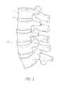
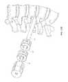
- FIG. 1is a lateral elevational view of a portion of a vertebral column.
- FIG. 2is a schematic side view of Kambin's triangle.
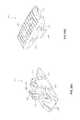
- FIG. 4Ais a plan view of a first and second dilator tubes in a combined position.
- FIG. 4Bis an enlarged detail view of the distal tip of the first and second dilator tubes shown in FIG. 4A .
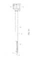
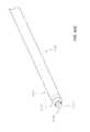
- FIG. 5Ais a plan view of a third dilator tube.
- FIG. 5Bis an enlarged detail view of the distal tip of the third dilator tube shown in FIG. 5A .
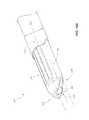
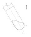
- FIG. 6Ais a side view of the access cannula shown in FIG. 3 .
- FIG. 6Bis an enlarged detail view of the distal tip of the access cannula shown in FIG. 6A .
- FIG. 8Ais a perspective view of the dilation introducer of FIG. 7A positioned against the spine.
- FIG. 8Bis an enlarged detail view of the second dilator tube of FIG. 7A introduced over the first dilator tube of FIG. 7A .
- FIG. 9is a perspective view of the dilation introducer of FIG. 7A , with the third dilator tube introduced over the second dilator tube.
- FIGS. 10A-10Dshow another embodiment in which a trocar is used in place of the first dilator tube.
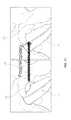
- FIG. 11shows the access point before and after the foraminoplasty performed by the dilation introducer of FIG. 7A .
- FIG. 12Ais a perspective view of the dilation introducer of FIG. 7A , with the access cannula introduced over the third dilator tube.
- FIG. 12Bis a perspective view of the dilation introducer of FIG. 7A , with the access cannula rotated to protect the exiting nerve.
- FIG. 12Cis a perspective view of the dilation introducer of FIG. 7A , with the first, second, and third dilator tubes removed, while the access cannula remains in place.
- FIG. 13is a plan view of an intervertebral implant for delivery through the access cannula.
- FIG. 14Ais a plan view of another embodiment of a first dilator tube.
- FIG. 14Bis an enlarged detail view of the distal end of the first dilator tube shown in FIG. 14A .
- FIG. 14Cis an enlarged detail view of the proximal end of the first dilator tube shown in FIG. 14A .
- FIG. 15Ais a plan view of another embodiment of a second dilator tube.
- FIG. 15Bis an enlarged detail view of the distal end of the second dilator tube shown in FIG. 15A .
- FIG. 16Ais a plan view of another embodiment of a third dilator tube.
- FIG. 16Bis an enlarged detail view of the distal end of the third dilator tube shown in FIG. 16A .
- FIGS. 16C and 16Dare enlarged detail views of the proximal end of the third dilator tube shown in FIG. 16A .
- FIG. 17Ais a plan view of another embodiment of an access cannula.
- FIG. 17Bis an enlarged detail view of the distal end of the access cannula shown in FIG. 17A .
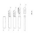
- FIG. 18Ais a plan view of another embodiment of a dilation introducer comprising the first dilator tube of FIG. 14A , the second dilator tube of FIG. 15A , the third dilator tube of FIG. 16A , and the access cannula of FIG. 17A .
- FIG. 18Bis an enlarged detail view of the distal end of the dilation introducer shown in FIG. 18A .
- FIG. 18Cis an enlarged detail view of the proximal end of the dilation introducer shown in FIG. 18A .
- FIG. 19Ais a longitudinal cross-sectional view of the dilation introducer of FIG. 18A .
- FIG. 19Bis an enlarged detail of the longitudinal cross-sectional view shown in FIG. 19A .
- FIG. 20Ais a plan view of a dilation introducer equipped with neuro-monitoring leads and a neuro-monitoring needle.
- FIG. 20Cis an enlarged detail view of a distal tip of a neuro-monitoring needle of FIG. 20A .
- FIG. 20Dis an enlarged detail view of the neuro-monitoring leads shown in FIG. 20A .
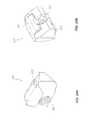
- FIG. 21Ais a perspective view of another embodiment of an intervertebral implant in an unexpanded state.
- FIG. 21Bis a perspective view of the intervertebral implant shown in FIG. 20A wherein the implant is in an expanded state.
- FIG. 22is a bottom view of the intervertebral implant shown in FIG. 21A .
- FIG. 23is a side view of the intervertebral implant shown in FIG. 21B .
- FIG. 24is a front cross-sectional view of the intervertebral implant shown in FIG. 21B taken along lines 19 - 19 .
- FIG. 25Ais a bottom perspective view of a lower body portion of the intervertebral implant shown in FIG. 24A .
- FIG. 25Bis a top perspective view of the lower body portion of the intervertebral implant shown in FIG. 24A .
- FIG. 26Bis a top perspective view of the upper body portion of the intervertebral implant shown in FIG. 24A .
- FIG. 27is a perspective view of an actuator shaft of the intervertebral implant shown in FIG. 21A .
- FIG. 28Ais a front perspective view of a proximal wedge member of the intervertebral implant shown in FIG. 21A .
- FIG. 28Bis a rear perspective view of the proximal wedge member of the intervertebral implant shown in FIG. 21A .
- FIG. 29Ais a front perspective view of a distal wedge member of the intervertebral implant shown in FIG. 21A .
- FIG. 30is a perspective view of a deployment tool according to an embodiment.
- FIG. 31is a side cross-sectional view of the deployment tool shown in FIG. 30 wherein an expandable implant is attached to a distal end thereof
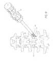
- FIG. 32is a perspective view of a rasp tool, according to an embodiment.
- FIG. 33Ais a plan view of a plunger assembly for a graft delivery system, according to an embodiment.
- FIG. 33Bis is a longitudinal cross-sectional view of the plunger assembly shown in FIG. 33A .
- FIG. 34Ais a plan view of a funnel assembly for a graft delivery system, according to an embodiment.
- FIG. 34Bis a schematic view of the funnel assembly shown in FIG. 34A .
- FIG. 34Cis an end view of the funnel assembly shown in FIG. 34A .
- FIG. 34Dis a longitudinal cross-sectional view of the funnel assembly shown in FIG. 34A .
- intervertebral implant and spinal fusionare discussed in the context of an intervertebral implant and spinal fusion because of the device and methods have applicability and usefulness in such a field.
- the devicecan be used for fusion, for example, by inserting an intervertebral implant to properly space adjacent vertebrae in situations where a disc has ruptured or otherwise been damaged.
- “Adjacent” vertebraecan include those vertebrae originally separated only by a disc or those that are separated by intermediate vertebra and discs. Such embodiments can therefore be used to create proper disc height and spinal curvature as required in order to restore normal anatomical locations and distances.
- teachings and embodiments disclosed hereincan be beneficially implemented in a variety of other operational settings, for spinal surgery and otherwise.
- FIG. 1is a lateral view of a vertebral column 10 .
- the vertebral column 10comprises a series of alternative vertebrae 11 and fibrous intervertebral discs 12 that provide axial support and movement to the upper portions of the body.
- the vertebral column 10typically comprises thirty-three vertebrae 11 , with seven certical (C 1 -C 7 ), twelve thoracic (T 1 -T 12 ), five lumbar (L 1 -L 5 ), five fused sacral (S 1 -S 5 ), and four fused coccygeal vertebrae.
- FIG. 2is a schematic view of Kambin's triangle.
- This region 20is the site of posterolateral access for spinal surgery. It can be defined as a right triangle over the intervertebral disc 12 viewed dorsolaterally.
- the hypotenuseis the exiting nerve 21
- the baseis the superior border of the inferior vertebra 22
- the heightis the traversing nerve root 23 .
- the intervertebral disc 12is accessed through this region by performing a foraminoplasty in which a portion of the inferior vertebra is removed such that surgical instruments or implants can be introduced at this region of the spine. In such a procedure, it is often desired to protect the exiting nerve and the traversing nerve root.
- Apparatuses and methods for accessing the intervertebral disc through Kambin's trianglemay involve performing endoscopic foraminoplasty while protecting the nerve will be discussed in more detail below.
- Utilizing foraminoplasty to access the intervertebral disc through Kambin's trianglecan have several advantages (e.g., less or reduced trauma to the patient) as compared to accessing the intervertebral disc posteriorly or anteriorly as is typically done in the art.
- surgical procedures involving posterior accessoften require removal of the facet joint.
- transforaminal interbody lumbar fusiontypically involves removal of one facet joint to create an expanded access path to the intervertebral disc. Removal of the facet joint can be very painful for the patient, and is associated with increased recovery time.
- accessing the intervertebral disc through Kambin's trianglemay advantageously avoid the need to remove the facet joint.
- endoscopic foraminoplastymay provide for expanded access to the intervertebral disc without removal of a facet joint. Sparing the facet joint may reduce patient pain and blood loss associated with the surgical procedure.
- sparing the facet jointcan advantageously permit the use of certain posterior fixation devices which utilize the facet joint for support (e.g., trans-facet screws, trans-pedicle screws, and/or pedicle screws). In this manner, such posterior fixation devices can be used in combination with interbody devices inserted through the Kambin's triangle.
- FIGS. 2-7Billustrate an embodiment of a dilation introducer 100 that can be used to perform percutaneous orthopedic surgery.
- the dilation introducer in the illustrated embodimentscan comprise an access cannula 30 , and a first, second and third dilator tubes 40 , 45 , 60 .
- first, second and third dilator tubes 40modified embodiments can include more or less dilator tubes and/or dilator tubes with modified features.
- the access cannula 30can be eliminated from the introducer or modified.
- FIG. 3illustrates an embodiment of the access cannula 30 , which is shown in a position for performing surgery on an intervertebral disc, for instance transforaminal lumbar interbody fusion.
- the access cannula 30 in the illustrated embodimenthas an inner lumen 31 that allows for surgical instruments and devices to pass through it to access the intervertebral disc 12 .
- the distal tip of the cannulacan be oriented such that surgical instruments have access to the intervertebral disc without contacting with the exiting nerve.
- the position shown in FIG. 3can be achieved by following the method disclosed herein, discussed in more detail below.
- FIGS. 4A and 4Billustrate an embodiment of the first dilator tube 40 and second dilator tube 45 of the dilation introducer 100 .
- the first dilator tube 40has a distal portion 41 , an outer radius 42 and a first longitudinal lumen 43 .
- the illustrated second dilator tube 45has a distal portion 46 , an outer radius 47 and a second longitudinal lumen 48 .
- the first dilator tubecan be received within the lumen of the second dilator tube.
- the outer radius 42 of the first dilator tubecan be centered around a first longitudinal axis 44 .
- the outer radius 47 of the second dilator tubecan be centered around a second longitudinal axis 49 .
- the second longitudinal axis 49is laterally offset from the first longitudinal axis 44 .
- the outer radius of the first dilator tubeis nearly equivalent to the inner radius of the second longitudinal lumen such that the first dilator tube can be slidably received within the second dilator tub.
- the second dilator tube 45can include a handle 50 for rotating the tube independently of the first dilator tube 40 .
- a collarcan be located distal to the handle, with an outer radius larger than the outer radius of the second dilator tube, but smaller than the outer radius of the handle.
- the first dilator tube 40can also a separate handle which can be locked together with the handle 50 of the second dilator tube 45 .
- the first and second dilator tubes 40 , 45can locked longitudinally locked together, such that slidable movement of the first tube with respect to the second is restricted.
- the distal portion 46 of the second dilator tubehas a flattened edge. This flattened edge advantageously prevents the second dilator tube 45 from penetrating the disc.
- FIG. 4Bshows an enlarged detail view of the distal portions of the first and second dilator tubes 40 , 45 of FIG. 4A .
- the distal portion 46 of the second dilator tube 45can have a generally semi-annular cross-section, configured such that when the first dilator tube 40 is received within the second dilator tube 45 , the outer radial surface of the first dilator tube 40 is partially exposed at the distal portion 46 of the second dilator tube 45 .
- the opening of the generally semi-annular cross-section of the second dilator tubecan be oriented opposite the second longitudinal axis 49 with respect to the first longitudinal axis 44 .
- the second dilator tubecan include cutting flutes or ridges 51 on one side, located opposite the opening of the generally semi-annular cross-section of the second dilator tube 45 .
- the cutting flutesmay be replaced with a coarse surface (e.g., knurling, sharp edges, abrasive members, etc.) which, when rotated or slid (e.g., back and forth) against bone, will create a recess therein.
- a coarse surfacee.g., knurling, sharp edges, abrasive members, etc.
- the cutting flutesare shown here by way of example only.
- the inner lumen of the second dilator tube 45can be off-center. In this configuration, the cutting flutes 51 are further from the axis of rotation than the side opposite the cutting flutes. This is particularly advantageous for performing foraminoplasty while protecting the exiting nerve, as will be discussed in more detail below.
- first and second dilator tubescan be coupled formed together as one unified dilator tube with a staggered distal portion.
- first dilator tube and second dilator tubemay be coupled together to form a single component.
- the tubesmay be joined by, for instance, welding, adhesive, mechanical joints, or any other appropriate means.
- the first dilator tubemay be omitted.
- a Jamshidi® needle with a removable handle, or a similar devicemay be used to initially define a path to the intervertebral disc. With the handle of the Jamshidi® needle removed, the second dilator tube may be advanced over the Jamshidi® needle, just as with the first dilator tube.
- a K-wire or similar devicecan be inserted through the Jamshidi® needle and/or dilator tubes.
- FIGS. 5A and 5Billustrate and embodiment of the third dilator tube 60 , which can be configured to be slidably introduced over the second dilator tube 45 .
- the third dilator tube 60can include a distal portion 61 , a third outer radius 62 centered around a third longitudinal axis 63 , and a third longitudinal lumen 64 having a third inner radius 65 .
- the third lumen 64can be configured to removably receive the second dilator tube (not shown) for slidable movement within the third lumen 64 .
- the third longitudinal axis 63is parallel to and laterally offset from the second longitudinal axis 49 .
- a handle 66can allow for rotation of the third dilator tube.
- a collarcan be located distal to the handle 66 , with an outer radius larger than the outer radius of the third dilator tube 45 , but smaller than the outer radius of the handle.
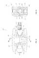
- a button 67 on the handle 66allows for the operator to toggle between a locked and unlocked configuration.
- a locked configurationthe second and third dilator tubes are unable to slide relative to one another.
- the locked configurationpermits the dilator tubes to rotate independently with respect to one another.
- the locked configurationrestrains rotational movement as well as slidable movement.
- the button 67may comprise a generally rectangular shape with a cut-out large enough for the collar of the second dilator tube 45 to pass therethrough. A spring located underneath the button 67 provides upward pressure on the button.
- the cut-out portion of the buttonWhen uncompressed, the cut-out portion of the button presses firmly against the collar of the second dilator tube 45 , which may be received within the handle 66 of the third dilator tube. When uncompressed, the friction of the button 67 against the collar inhibits movement of the third dilator tube 60 with respect to the second dilator tube.
- the cut-out portion of the buttonmay form a notch configured to fit within the ridge on the collar of the third dilator tube. Upon compressing the button 67 , the cut-out portion of the button may be moved away from the collar, permitting free movement of the third dilator tube 60 relative to the second dilator tube 45 .
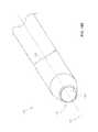
- FIGS. 6A and 6Billustrate an embodiment of the access cannula, which can be configured to be introduced over the third dilator tube (not shown).
- the access cannula 30has a distal portion 32 , a fourth outer radius 33 centered around a fourth longitudinal axis 34 , and a fourth longitudinal lumen 31 having a fourth inner radius 35 .
- the access cannula 30may be configured to removably receive the third dilator tube (not shown) for slidable movement within the third lumen.
- a handleallows for rotation of the access cannula 30 .
- a button 37 on the handle 36allows for the operator to toggle between a locked and unlocked configuration.
- a locked configurationthird dilator tube and the access cannula are unable to slide relative to one another.
- the locked configurationpermits the dilator tubes to rotate independently with respect to one another.
- the locked configurationrestrains rotational movement as well as slidable movement.
- the button 37may comprise a generally rectangular shape with a cut-out large enough for the collar of the third dilator tube 60 to pass therethrough. A spring located beneath the button 37 can provide upward pressure on the button.
- FIGS. 7A and 7Billustrate one embodiment of the dilation introducer 100 in an assembled configuration.
- the access cannula 30can be positioned over the third dilator tube 60 , which can be positioned over the second dilator tube 45 , which in turn can be positioned over the first dilator tube 40 .
- the handles 50 , 151 of the first and second dilator tubescan be locked together to constrain slidable movement, but allow for the second dilator tube 45 to rotate with respect to the first dilator tube 40 .
- the third dilator tube 60can be advanced distally until the distal portion 61 of the third dilator tube aligns with the distal portion 46 of the second dilator tube.
- the access cannulamay also be advanced so that the distal portion 32 aligns with the distal portions 46 , 61 of the second and third dilator tubes.
- the second and third dilator tubes 45 , 60each have cutting flutes 51 , 68 on their respective distal portions 46 , 61 .
- the first, second, and third longitudinal axes 44 , 49 , 63are each laterally offset from one another.
- the first, second and third dilator tubes along with the access cannulacan be provided with additional stops that engage the buttons described above.
- additional stopsthat engage the buttons described above.
- notches or detentscan be provided that engage the button when one tube is advanced distally and reaches a specific location (e.g., end point). In this manner, forward movement of a tube or cannula can be limited once the tube or cannula may be advanced to a desired location
- FIG. 7Bshows an enlarged detail view of the dilation introducer of FIG. 7A .
- the distal portions 46 , 61 , 32 of each of the second and third dilator tubes 45 , 60 , and of the access cannula 30have generally semi-annular cross-sections.
- the distal portions 46 , 61 of the second and third dilator tubes in the illustrated embodimentcan have flattened edges, to prevent penetration into the intervertebral disc as each dilator tube is advanced.
- FIGS. 8A-13illustrate one embodiment of a method of performing percutaneous orthopedic surgery using the dilation introducer.
- the first dilator tube 40can be placed through Kambin's triangle 20 until the distal portion 41 abuts or even penetrates the intervertebral disc 12 .
- the second dilator tube 45can then be advanced over the first dilator tube 40 until the distal portion 46 of the second dilator tube abuts but does not enter the intervertebral disc 12 .
- the first dilator tubemay be omitted.
- a Jamshidi® needle with a removable handle or similar devicemay be used.
- the Jamshidi® needlemay be first introduced to abut or enter the intervertebral disc, after which the handle may be removed.
- a K-wiremay be inserted into the Jamshidi® needle after it is in position either abutting or partially penetrating the intervertebral disc.
- the second dilator tubemay then be advanced over the Jamshidi® needle.
- FIG. 8Bshows an enlarged detail of the second dilator tube 45 introduced over the first dilator tube 40 .
- the distal portion 46 of the second dilator tube 45can have a semi-annular cross-section with an opening that forms a recess with respect to the leading edge of the tube 45 .
- the second dilator tube 45can be oriented for advancement over the first dilator tube 40 such that the opening of the semi-annular cross-section faces the exiting nerve 21 . This technique advantageously limits and/or eliminates contact with the exiting nerve.
- the distal portion 46 of the second dilator tube opposite the opening of the semi-annular cross-sectionabuts the inferior vertebrae 22 .
- the cutting flutesare positioned against the inferior vertebrae 22 .
- the second dilator tube 45may be rotated slightly back and forth, such that the cutting flutes create a recess in the inferior vertebrae 22 , making room for introduction of the third dilator tube.
- careis taken to minimize any trauma inflicted upon the exiting nerve.
- the tube 45can be used to remove bone on a side of the tube 45 generally opposite of the nerve 21 .
- the third dilator tube 60can be introduced over the second dilator tube 45 .
- the distal portion 61 of the third dilator tube 60abuts but does not enter the intervertebral disc.
- a flattened edge of the distal portioncan help ensure that the third dilator tube 60 does not penetrate the intervertebral disc or limit such penetration.
- the opening of the semi-annular cross-section of the distal portion of the third dilator tubecan be positioned to face the exiting nerve (not shown). Contact between the third dilator tube 60 and the nerve can thereby be minimized or eliminated.
- the cutting flutes 68 of the third dilator tubecan be positioned opposite the opening of the semi-annular cross-section, and abut the inferior vertebrae 22 .
- the third dilator tube 60may be rotated slightly back and forth, such that the cutting flutes create a further recess in the inferior vertebrae 22 , making room for introduction of the access cannula. Again, care should be taken during the rotation of the third dilator tube to ensure that the exiting nerve is not injured thereby. Accordingly, the third dilator tube can be can be used to remove bone on a side of the tube 60 generally opposite of the nerve 21 .
- FIGS. 10A-Dshow an alternative method in which a trocar can be used in place of the first dilator tube.
- the insertion point and access trajectorycan first be determined.
- a patientmay lie face down on a surgical frame to facilitate a lordotic position of the lumbar spine.
- a K-wire(or equivalent) can be laid beside the patient and placed to the depth of optimal insertion for the intervertebral implant. Intersection with the skin can be marked on the K-wire (or equivalent).
- the K-wire(or equivalent) can be laid on top of the patient, aligned with the disc in a view that allows for the end plates to be parallel (e.g., Ferguson View or Reverse Ferguson, as applicable).
- the distance between the midline and the previously marked point on the K-wirecan define the insertion point.
- a small skin incisioncan be made defining a trajectory into the disc can be between 45 and 55 degrees.
- a trocar 90can be placed into the center of the disc 12 of the level to be treated, up to but not through the distal annulus.
- an 11 gauge to 18 gauge access needlecan be used.
- the inner stylet 92 of the trocar(if present) can be removed while maintaining the outer sheath 94 in place within the disc 12 .
- a K-wirecan be inserted into the disc and the outer sheath may be removed.
- a dilation introducer 96can be placed over the outer sheath 94 of the trocar (or over the K-wire, if applicable).
- the dilation introducer 96can be aligned so that the smooth edges are oriented towards the exiting nerve root and the foramen.
- the dilation introducer 96can include at least second and third dilator tubes, each having cutting flutes adapted to perform foraminoplasty for improved access to the disc space.
- the dilation introducer 96can function substantially as described elsewhere herein, except that the trocar 90 has replaced the first dilator tube.
- the second dilator tubesmay be rotated within +/ ⁇ 45 degrees around the longitudinal axis so that the cutting flutes do not contact the exiting nerve.
- FIG. 11shows the access area before and after the second and third dilator tubes 45 , 60 are rotated to create a recess in the inferior vertebrae 22 .
- the area 70 in the left image demarcated by a dashed lineis the portion of bone that can be removed by the second and third dilation tubes 45 , 60 .
- This foraminoplastypermits the access cannula to be introduced without disturbing the exiting nerve 21 .
- the method describedis not limited by the precise location of the recess shown in FIG. 11 . In general, a recess may be formed anywhere along the superior border of the inferior vertebrae 22 , in order to provide improved access for a dilation introducer.
- FIG. 12Ashows the access cannula 30 introduced over the third dilator tube 60 .
- the distal portion 32 of the access cannula 30abuts but does not enter the intervertebral disc 12 .
- the distal portion 32can be equipped with flattened edges to guard against insertion into the intervertebral disc.
- the opening of the semi-annular cross-section of the distal portion 32 of the access cannula 30can be positioned initially to face the exiting nerve (not shown). Contact between the access cannula 30 and the exiting nerve can thereby be minimized during insertion.
- the access cannula 30can then be rotated such that the opening of the semi-annular cross-section faces opposite the exiting nerve (not shown). Since, unlike the second and third dilator tubes 45 , 60 , the outer surface of the access cannula is smooth, trauma to the exiting nerve may be minimized during this rotation.
- the cannula 30can be rotated so that the opening of the semi-annular cross-section faces opposite the exiting nerve (not shown), the first, second, and third dilator tubes 40 , 45 , 60 may be removed.
- rotation of the cannula 30can gently move the nerve away from the access site while also protecting the nerve as tools and devices may be inserted through the cannula 30 .
- the access cannula 30can then provide an open lumen 31 through which surgical tools can be introduced to the site of the intervertebral disc 12 .
- the positioning of the access cannula 30protects the exiting nerve (not shown) from coming into contact with any of the surgical tools.
- FIG. 13A example of a surgical tool for use through the access cannula is depicted in FIG. 13 .
- the intervertebral implant 80may be introduced through the access cannula 30 , and released once in position. Although a particular intervertebral implant is shown here, one of skill in the art will readily understand that any number of surgical tools may be introduced through the access cannula.
- surgical tools to be inserted through the access cannulamay include, without limitation, discectomy tools, tissue extractors, bone graft insertion tools, rasps, forceps, drills (e.g,. trephine), rongeurs, curettes, paddle distractors, mechanical distractors, lasers, automated probes, manual probes, and plasma wands.
- an opening in the disc annuluscan be formed and a portion of the disc can be removed using tools advanced through the access cannula 30 .
- the disc spacecan be distracted (e.g,. using paddle distractors) before and/or after the implant 80 and/or different or additional interbody devices are inserted through the access cannula 30 and placed between the vertebral bodies to maintain spacing.
- the disc nucleus or portions thereofis removed while leaving the disc annulus.
- Bone graft and/or other materialssuch as, for example, bone morphogenetic proteins (BMPs) can be placed between the vertebrae before, while or after positioning the implant. Fusion can then occur between the vertebrae.
- BMPsbone morphogenetic proteins
- fusioncan be augmented with other fixation devices such as, for example, pedicle screws and rod constructions, transfacet and transpedicle screws, interbody spacers, rods, plates and cages, which can be used to stabilize a pair of vertebral bodies together.
- fixation devicessuch as, for example, pedicle screws and rod constructions, transfacet and transpedicle screws, interbody spacers, rods, plates and cages, which can be used to stabilize a pair of vertebral bodies together.
- the fusionis augmented by one or more posterior fixation devices (e.g transfacet and transpedicle screws and/or pedicle screws and rods and/or spinous process spacers).
- posterior fixation devicese.g transfacet and transpedicle screws and/or pedicle screws and rods and/or spinous process spacers.
- the entire fusion procedurecan be done from a posterior position and preferably in a minimally invasive (e.g., percutaneous manner).
- the above described procedureis used in combination with the transfacet-pedicular implant system sold by Intervention Spine, Inc. under the trade name PERPOS®, such a system is also described in U.S. Pat. Nos. 7,998,176 and 7,824,429, the entirety of which are hereby incorporated by reference herein.
- FIGS. 14-20Dillustrate another aspect of a dilation introducer 1100 that can be used to perform percutaneous orthopedic surgery.
- the dilation introducer in this embodimentis similar in some respects to that described above.
- the proximal portion of the dilation introducer 1100differs significantly from that of the dilation introducer 100 described above.
- the dilation introducer 1100 in the illustrated embodimentscan comprise an access cannula 130 , and a first, second and third dilator tubes 140 , 145 , 160 .
- first, second and third dilator tubes 140While the illustrated embodiment includes first, second and third dilator tubes 140 , modified embodiments can include more or less dilator tubes and/or dilator tubes with modified features.
- the access cannula 130can be eliminated from the introducer or modified.
- FIGS. 14A to 14Cillustrate an embodiment of the first dilator tube 140 of the dilation introducer 1100 .
- the first dilator tube 140may have distal portion 141 , an outer radius 142 and a first longitudinal lumen 143 .
- the outer radius 142can be centered around first longitudinal axis 144 .
- the distal portion 141may include a tapered tip 171 of the dilator tube.
- the proximal portion 172 of the first dilator tubemay include a first proximal head 173 , with a threaded portion 174 distal to the gripping portion 175 .
- the longitudinal lumen 143extends through the proximal head 173 , such that a guidewire or K-wire may be introduced through the proximal head 173 and the dilator tube 140 .
- FIGS. 15A to 15Cillustrate an embodiment of the second dilator tube 145 .
- the second dilator tubehas a distal portion 146 , and an outer radius 147 .
- the outer radiusmay be centered around a second longitudinal axis 149 .
- the second dilator tubeincludes a second longitudinal lumen 48 with an inner radius 176 .
- the outer radius 142 of the first dilator tubemay be nearly equivalent to the inner radius 176 of the second dilator tube, such that the first dilator tube 140 can be slidably received within the second longitudinal lumen 148 .
- the proximal portion 177 of the second dilator tubeincludes a collar 178 .
- the longitudinal axis 127 of the second longitudinal lumenis essentially aligned with the first longitudinal axis 144 .
- the second dilator tube 145can include cutting flutes or ridges 151 on one side, located opposite the opening of the generally semi-annular cross-section of the second dilator tube 145 .
- the cutting flutes 151may be replaced with a coarse surface (e.g., knurling, sharp edges, abrasive members, etc.) which, when rotated or slid (e.g., back and forth) against bone, will create a recess therein.
- the cutting flutesare shown here by way of example only.
- the inner lumen 148 of the second dilator tube 145can be off-center.
- the cutting flutes 151are further from the axis of rotation than the side opposite the cutting flutes. This is particularly advantageous for performing foraminoplasty while protecting the exiting nerve, as will be discussed in more detail below.
- FIG. 15Cshows an enlarged detail view of the proximal portion 177 of the second dilator tube 145 .
- the collar 178includes an aperture 181 which may be used in conjunction with the third dilator tube, as described in detail below.
- the aperture 181may be instead replaced with a circumferentially oriented groove.
- FIGS. 16A to 16Dillustrate and embodiment of the third dilator tube 160 , which can be configured to be slidably introduced over the second dilator tube 145 .
- the third dilator tube 160can include a distal portion 161 , a third outer radius 162 centered around a third longitudinal axis 163 , and a third longitudinal lumen 164 having a third inner radius 165 centered around longitudinal axis 169 that runs parallel to and laterally offset from the third longitudinal axis 163 .
- the third lumen 164can be configured to removably receive the second dilator tube 145 for slidable movement within the third lumen 164 .
- the second longitudinal axis 149essentially aligns with the longitudinal axis 169 of the inner lumen 164 of the third dilator tube 160 .
- the proximal portion 182includes a handle assembly 183 .
- FIG. 16Bshows an enlarged detail view of the distal portion of the third dilator tube of FIG. 16A .
- the distal portion 161 of the third dilator tubemay include a flattened edge 185 .
- This flattened edge 185advantageously prevents the third dilator tube 160 from penetrating the intervertebral disc 112 .
- the tip 184 of the distal portion 161has a generally semi-annular cross-section, and cutting flutes 167 for reaming bone located opposite the opening of the semi-annular cross-section.
- the cutting flutesmay be replaced or used in combination with a coarse or other cutting or abrading surface which, when rotated or slid against bone, will create a recess therein.
- the longitudinal lumen 164 of the third dilator tube 160may be off-center.
- the cutting flutes 167are further from the axis of rotation than the side opposite the cutting flutes. This is particularly beneficial for performing foraminoplasty while protecting the exiting nerve, as will be discussed in more detail below.
- FIGS. 16C and 16Dshow enlarged detail views of the proximal portion 182 of the third dilator tube 160 .
- the proximal portion 182includes a handle assembly 183 .
- a first latching button 186may be configured for constraining the movement of the third dilator tube relative to the second dilator tube, as described in more detail below. In various embodiments, the latching button 186 may constrain slidable movement, rotational movement, or both.
- a second latching button 187may be located distal the first latching button 186 , and may be configured to constrain the movement of the access cannula relative to the third dilator tube, as described in more detail below.
- the distal end of the handle assembly 183includes an overhanging lip 191 into which the proximal grip 136 of the access cannula can be removably received.
- the locking pin 1103slides within the locking pinhole 1104 on the proximal grip 136 of the access cannula, thereby restricting rotational movement of the access cannula relative to the third dilator tube.
- the locking pinholemay be omitted, permitting rotation of the access cannula 130 relative to the third dilator tube 60 .
- FIGS. 17A to 17Cillustrate an embodiment of the access cannula 130 , which can be configured to be introduced over the third dilator tube 145 .
- the access cannula 130has a distal portion 132 , a fourth longitudinal axis 134 , and a fourth longitudinal lumen 131 having a fourth inner radius 135 .
- the access cannula 130may be configured to removably receive the third dilator tube (not shown) for slidable movement within the third lumen.
- a handle 136allows for rotation of the access cannula 130 .
- FIG. 17Bshows an enlarged detail view of the distal portion of the access cannula of FIG. 17A .
- the distal portion 132can have a generally semi-annular cross-section.
- the fourth longitudinal lumenmay be centered with respect to the outer radius of the access cannula, in contrast to the second and third dilator tubes.
- the access cannulamay also have a longitudinal lumen that is off-center with respect to the outer radius.
- the access cannulaneed not be limited to a cylindrical outer surface. The outer surface could, for instance, have an elliptical, polygonal, or other cross-sectional shape.
- FIGS. 18A to 18Cillustrate one embodiment of the dilation introducer 1100 in an assembled configuration.
- the access cannula 130can be positioned over the third dilator tube 160 , which can be positioned over the second dilator tube 145 , which in turn can be positioned over the first dilator tube 140 .
- the handle assembly 183 of the third dilator tubemay be in a locked configuration with the proximal grip 136 of the access cannula can be locked together to constrain slidable movement, but allow for the access cannula 130 to rotate with respect to the third dilator tube 160 .
- the second dilator tube 145may be locked together with the third dilator tube to constrain slidable movement, while still allowing the second dilator tube 145 to rotate with respect to the third dilator tube.
- the second dilator tubemay be in a locked configuration preventing both slidable and rotational movement with respect to the third dilator tube 145 .
- the third dilator tube 60can be advanced distally until the distal portion 161 of the third dilator tube aligns with the distal portion 46 of the second dilator tube.
- the access cannula 130may also be advanced so that the distal portion 32 aligns with the distal portions 146 , 161 of the second and third dilator tubes.
- the second and third dilator tubes 145 , 160each have cutting flutes 151 , 167 on their respective distal portions 146 , 161 .
- the first, second, and third longitudinal axes 144 , 149 , 163are each laterally offset from one another.
- the first, second and third dilator tubes 140 , 145 , 160 along with the access cannula 130can be provided with additional stops that engage the proximal grip 136 of the access cannula and the handle assembly 183 of the third dilator tube described above.
- additional stopsthat engage the proximal grip 136 of the access cannula and the handle assembly 183 of the third dilator tube described above.
- notches or detentscan be provided that engage the proximal grip 136 or handle assembly 183 when one tube is advanced distally and reaches a specific location (e.g., end point). In this manner, forward movement of a tube or cannula can be limited once the tube or cannula is advanced to a desired location
- FIG. 18Bshows an enlarged detail view of the distal portion of the dilation introducer of FIG. 18A .
- the distal portions 146 , 161 , 132 of each of the second and third dilator tubes 145 , 160 , and of the access cannula 130may have generally semi-annular cross-sections.
- the distal portions 146 , 161 of the second and third dilator tubes 145 , 160 in the illustrated embodimentcan have flattened edges 179 , 185 to prevent penetration into the intervertebral disc as each dilator tube is advanced.
- FIG. 18Cshows an enlarged detail view of the proximal portion of the dilation introducer of FIG. 18A .
- the proximal grip 136 of the access cannula 130is shown in a locked configuration with the handle assembly 183 of the third dilator tube 160 .
- the smaller diameter portion(not shown) may be received within the overhanging lip 191 on the distal end of the handle assembly 183 .
- Latching buttons 186 , 187constrain movement of the third dilator tube relative to the second dilator tube, and of the access cannula relative to the third dilator tube, respectively.
- the gripping portion 175 of proximal head 173 of the first dilator tube 140is visible at the proximal end of the dilation introducer.
- the first dilator tubemay be fastened to the handle assembly 183 by means of the threaded portion 174 (not shown) on the proximal head 173 and the threaded receiving portion 190 (not shown) of the handle assembly 183 . As shown, this fastening constrains both rotational and slidable movement of the first dilator tube relative to the third dilator tube.
- the first dilator tubemay be affixed to the handle assembly 183 by other means that allow for free rotational movement, free slidable movement, or both.
- the dilation introducer 1100includes a first dilator tube 140 , a second dilator tube 145 , a third dilator tube 160 , and an access cannula 130 .
- the first dilator tubehas a distal portion 141 with a tapered tip 171 , and a proximal portion 172 having a proximal head 173 .
- the first dilator tube 140may be cannulated, for example to allow passage of a guide wire down the longitudinal axis 143 of the first dilator tube 140 , or the first dilator tube may be without a lumen and uncannulated.
- the second dilator tube 145has a distal tip 180 with a flattened edge 179 , a proximal portion 177 with a collar 178 , and a longitudinal lumen 148 .
- the first dilator tube 140may be removably received within the second dilator tube 145 .
- the third dilator tube 160has a distal tip 184 with a flattened edge 185 , a proximal portion 182 with a handle assembly 183 , and a longitudinal lumen 164 .
- the second dilator tube 145may be removably received in the longitudinal lumen 164 of the third dilator tube 160 for slidable movement within the third dilator tube 160 .
- the threaded portion 174 of the proximal head 173 of the first dilator tubeengages with the interior threaded receiving portion 190 of the handle assembly 183 of the third dilator tube 160 .
- the first and third dilator tubes 140 , 160may be locked together for length and rotation.
- the second and third dilator tubesmay be connected together in a locked configuration with a first latching button 186 disposed on the handle assembly 183 of the third dilator tube 160 and extending through a first aperture 1105 in the handle assembly 183 of the third dilator tube 160 , so that the first latching button 186 may be moveable between a radially inward locking position (arrow 1101 ) and a radially outward unlocking position (arrow 1102 ).
- the distal end 196 of the first latching buttonmay be removably received in aperture 181 of the second dilator tube 145 so as to engage and lock the second and third dilators together in the locking position.
- the latching buttonmay be received in a circumferentially oriented groove of the second dilator tube, which may or may not extend completely around the second dilator tube.
- the first latching button 186may be pulled radially outwardly to release the second dilator tube 145 , to allow the third dilator tube 160 to slide with respect to the second dilator tube 145 .
- the proximal portion 193 of the access cannula 130includes a proximal grip 136 with a larger diameter portion 198 and a smaller diameter portion 199 .
- the smaller diameter portion 199may be sized to fit under an overhanging lip 191 of the third dilator tube, when the longitudinal axes of the third dilator tube and access cannula may be aligned.
- the circumferentially oriented channel 1107does not need to extend completely around the exterior of the smaller diameter portion 199 .
- the third dilator tube 145 and the access cannula 130may be connected together in a locked configuration with the second latching button 187 disposed on the overhanging lip 191 of the handle assembly 183 of the third dilator tube 145 .
- the second latching buttonextends through an aperture 1106 in the overhanging lip 191 of the handle assembly 183 and may be movable between a radially inward locking position (arrow 194 ) and a radially outward unlocking position (arrow 195 ).
- the distal end 197 of the second latching button 187may be removably received in the channel 107 located in the smaller diameter portion 199 of the access cannula 130 , in the locking position, to lock the third dilator tube 45 and the access cannula 130 in the locked assembled configuration.
- the second latching button 187may be pulled radially outward to release the access cannula 130 to slide to the unlocked configuration.
- the second and third dilator tubes 140 , 145may be removed together as a unit from the access cannula 130 .
- the first dilator tube 140 and second dilator tube 145can be kept locked together and can be removed from the access cannula 130 by unlocking the second latching button 187 alone.
- An advantage of this embodimentis that the latching buttons 186 , 187 may be both removable from the surgical field with the release of the third dilator tube from the access cannula 130 .
- the access cannulabeing free of protuberances, such as the latching buttons, is less likely to catch surgical sponges and sutures, for example, on the dilation introducer.
- a first neuro-monitoring lead 1113may be attached to the proximal portion 177 of the second dilator tube 145 .
- a second neuro-monitoring lead 1114may be attached to the proximal portion 183 of the third dilator tube 160 .
- the wire 1109may comprise a conductive material, such as silver, copper, gold, aluminum, platinum, stainless steel, etc.
- a constant currentmay be applied to the wire 1109 .
- the needle cannula 1110may be insulated by dielectric coating 1112 . Although the coating shown here is dielectric, any sufficiently insulative coating may be used. Alternatively, an insulative sleeve may encase the wire. This arrangement protects the conductive wire 1109 at all points except the most distal tip 1111 . As the exposed tip of the wire 1109 is advanced through the tissue, it continues to be supplied with current. When the tip 1111 approaches a nerve, the nerve may be stimulated. The degree of stimulation to the nerve is related to the distance between the distal tip 1111 and the nerve. Stimulation of the nerve may be measured by, e.g., visually observing the patient's leg for movement, or by measuring muscle activity through electromyography (EMG) or various other known techniques.
- EMGelectromyography
- the pincan aid in locating the second and third dilator tubes on x-ray or fluoroscopy, and additionally can faciliatate the transmission of current through the second and third dilator tubes to the area of contact.
- Electrode attachments for the second and third dilator tubescan be coated with parylene on the proximal larger diameter to prevent current from flowing into the user.
- the rest of the electrodecan be uncoated, but passivated to resist rusting, pitting, or corrosion.
- the electrodescan attach such that the current is transmitted to the internal area of the second and third dilator tubes so that it can be transmitted distally through the exposed areas on the tips of the tubes.
- These tubesare attached to Radel handles, which being a polymer are also insulators.
- the third dilator tubecan be made from stainless steel, coated with nylon or other polymer, such as Teflon, followed by a parylene coating. In embodiments in which the dilator tube comprises stainless steel, no additional x-ray marker
- the implant 80can comprise any of a variety of types of interbody devices configured to be placed between vertebral bodies.
- the implant 80can be formed from a metal (e.g., titanium) or a non-metal material such as plastics, PEEKTM, polymers, and rubbers. Further, the implant components can be made of combinations of non metal materials (e.g., PEEKTM, polymers) and metals.
- the implant 80can be configured with a fixed or substantially fixed height, length and width as shown, for example, in the embodiment of FIG. 13 . In other embodiments, the implant can be configured to be expandable along one or more directions. For example, in certain embodiments the height of the implant can be expanded once the device advanced through the access cannula and positioned between vertebral bodies (e.g., within the disc space within the annulus).
- the proximal and distal wedge members 206 , 208can include at least one guide member (an upper guide member 230 of the proximal wedge member 206 is shown in FIG. 21A and an upper guide member 232 of the distal wedge member 208 is shown in FIG. 23 ) that at least partially extends into a respective slot of the upper and lower body portions.
- the arrangement of the slots and the guide memberscan enhance the structural stability and alignment of the implant 200 .
- FIG. 21Bis a perspective view of the implant 200 wherein the implant 200 is in the expanded state.
- the upper and lower side portions 240 , 242can be configured to have complementary structures that enable the upper and lower body portions 202 , 204 to move in a vertical direction.
- the complementary structurescan ensure that the proximal ends of the upper and lower body portions 202 , 204 generally maintain spacing equal to that of the distal ends of the upper and lower body portions 202 , 204 .
- the complementary structuresare discussed further below with regard to FIGS. 22-26B .
- the complementary structurescan also include motion limiting portions that prevent expansion of the implant beyond a certain height. This feature can also tend to ensure that the implant is stable and does not disassemble during use.
- the actuator shaft 210can facilitate expansion of the implant 200 through rotation, longitudinal contract of the pin, or other mechanisms.
- the actuator shaft 210can include threads that threadably engage at least one of the proximal and distal wedge members 206 , 208 .
- the actuator shaft 210can also facilitate expansion through longitudinal contraction of the actuator shaft as proximal and distal collars disposed on inner and outer sleeves move closer to each other to in turn move the proximal and distal wedge members closer together.
- the actuator shaft 210can be configured to bring the proximal and distal wedge members closer together at different rates.
- the implant 200could be expanded to a V-configuration or wedged shape.
- the actuator shaft 210can comprise a variable pitch thread that causes longitudinal advancement of the distal and proximal wedge members at different rates. The advancement of one of the wedge members at a faster rate than the other could cause one end of the implant to expand more rapidly and therefore have a different height that the other end.
- Such a configurationcan be advantageous depending on the intervertebral geometry and circumstantial needs.
- the implant 200can be configured to include one or more apertures 252 to facilitate osseointegration of the implant 200 within the intervertebral space.
- the implant 200may contain one or more bioactive substances, such as antibiotics, chemotherapeutic substances, angiogenic growth factors, substances for accelerating the healing of the wound, growth hormones, antithrombogenic agents, bone growth accelerators or agents, and the like.
- various biologicscan be used with the implant 200 and can be inserted into the disc space or inserted along with the implant 200 .
- the apertures 252can facilitate circulation and bone growth throughout the intervertebral space and through the implant 200 . In such implementations, the apertures 252 can thereby allow bone growth through the implant 200 and integration of the implant 200 with the surrounding materials.
- FIG. 22is a bottom view of the implant 200 shown in FIG. 21A .
- the implant 200can comprise one or more protrusions 260 on a bottom surface 262 of the lower body portion 204 .
- the upper body portion 204can also define a top surface having one or more protrusions thereon.
- the protrusions 260can allow the implant 200 to engage the adjacent vertebrae when the implant 200 is expanded to ensure that the implant 200 maintains a desired position in the intervertebral space.
- the protrusions 260can be configured in various patterns. As shown, the protrusions 260 can be formed from grooves extending widthwise along the bottom surface 262 of the implant 200 (also shown extending from a top surface 264 of the upper body portion 202 of the implant 200 ). The protrusions 260 can become increasingly narrow and pointed toward their apex. However, it is contemplated that the protrusions 260 can be one or more raised points, cross-wise ridges, or the like.
- FIG. 22also illustrates a bottom view of the profile of an embodiment of the upper side portion 240 and the profile of the lower side portion 242 .
- the upper and lower side portions 240 , 242can each include complementary structures to facilitate the alignment, interconnection, and stability of the components of the implant 200 .
- FIG. 22also shows that in some embodiments, having a pair of each of upper and lower side portions 240 , 242 can ensure that the upper and lower body portions 202 , 204 do not translate relative to each other, thus further ensuring the stability of the implant 200 .
- the upper side portion 240can comprise a groove 266 and the lower side portion can comprise a rib 268 configured to generally mate with the groove 266 .
- the groove 266 and rib 268can ensure that the axial position of the upper body portion 202 is maintained generally constant relative to the lower body portion 204 . Further, in this embodiment, the grooves 266 and rib 268 can also ensure that the proximal ends of the upper and lower body portions 202 , 204 generally maintain spacing equal to that of the distal ends of the upper and lower body portions 202 , 204 .
- This configurationis also illustratively shown in FIG. 23 .
- the implant 200is illustrated in the unexpanded state with each of the respective slots 222 of the lower body portion 204 and lower guide members 270 , 272 of the respective ones of the proximal and distal wedge members 206 , 208 .
- the slots and guide memberscan be configured to incorporate a generally dovetail shape.
- the guide membercan only slide longitudinally within the slot and not vertically from the slot. This arrangement can ensure that the proximal and distal wedge members 206 , 208 are securely engaged with the upper and lower body portions 202 , 204 .
- a side view of the embodiment of the implant 200 in the expanded stateillustrates the angular relationship of the proximal and distal wedge members 206 , 208 and the upper and lower body portions 202 , 204 .
- the dovetail shape of the slots and guide membersensures that for each given slot and guide member, a given wedge member is generally interlocked with the give slot to only provide one degree of freedom of movement of the guide member, and thus the wedge member, in the longitudinal direction of the given slot.
- the wedge members 206 , 208may not be separable from the implant when the implant 200 is in the unexpanded state (as shown in FIG. 21A ) due to the geometric constraints of the angular orientation of the slots and guide members with the actuator shaft inhibiting longitudinal relative movement of the wedge members 206 , 208 relative to the upper and lower body portions 202 , 204 .
- Such a configurationensures that the implant 200 is stable and structurally sound when in the unexpanded state or during expansion thereof, thus facilitating insertion and deployment of the implant 200 .
- Such an embodiment of the implant 200can therefore be assembled by placing or engaging the wedge members 206 , 208 with the actuator shaft 210 , moving the wedge members 206 , 208 axially together, and inserting the upper guide members 230 , 232 into the slots 220 of the upper body portion 202 and the lower guide members 270 , 272 into the slots 222 of the lower body portion 204 .
- the wedge members 206 , 208can then be moved apart, which movement can cause the guide members and slots to engage and bring the upper and lower body portions toward each other.
- the implant 200can then be prepared for insertion and deployment by reducing the implant 200 to the unexpanded state.
- the upper and lower body portions 202 , 204can be configured to snap together to limit expansion of the implant 200 .
- the upper and lower side portions 240 , 242can comprise upper and lower motion-limiting structures 280 , 282 , as shown in the cross-sectional view of FIG. 24 .
- the upper motion-limiting structure 280can engage the lower motion-limiting structure 282 . This engagement can occur due to deflection of at least one of the upper and lower side portions 240 , 242 .
- the motion-limiting structures 280 , 282preferably comprise interlocking lips or shoulders to engage one another when the implant 200 has reached maximum expansion. Accordingly, after the wedge members 206 , 208 are assembled with the upper and lower body portions 202 , 204 , these components can be securely interconnected to thereby form a stable implant 200 .
- the implant 200can define generally convex top and bottom surfaces 264 , 262 .
- the shapecan be modified.
- FIGS. 25A-Billustrate perspective views of the lower body portion 204 of the implant 200 , according to an embodiment. These Figures provide additional clarity as to the configuration of the slots 222 , the lower side portions 242 , and the lower motion-limiting members 282 of the lower body portion 204 .
- FIGS. 26A-Billustrate perspective views of the upper body portion 202 of the implant 200 , according to an embodiment. These Figures provide additional clarity as to the configuration of the slots 220 , the upper side portions 240 , and the upper motion-limiting members 280 of the upper body portion 202 .
- the upper and lower body portions 202 , 204can also define a central receptacle 290 wherein the actuator shaft can be received. Further, as mentioned above, the upper and lower body portions 202 , 204 can define one or more apertures 252 to facilitate osseointegration.
- FIG. 27is a perspective view of an actuator shaft 210 of the implant 200 shown in FIG. 21 .
- the actuator shaft 210can be a single, continuous component having threads 294 disposed thereon for engaging the proximal and distal wedge members 206 , 208 .
- the threadscan be configured to be left hand threads at a distal end of the actuator shaft 210 and right hand threads at a proximal other end of the actuator shaft for engaging the respective ones of the distal and proximal wedge members 208 , 206 . Accordingly, upon rotation of the actuator shaft 210 , the wedge members 206 , 208 can be caused to move toward or away from each other to facilitate expansion or contraction of the implant 200 .
- this embodimentis described and illustrated as having the actuator shaft 210 with threads 294 .
- the actuator shaft 210can also comprise a tool engagement section 296 and a proximal engagement section 298 .
- the tool engagement section 296can be configured as a to be engaged by a tool, as described further below.
- the tool engagement section 296can be shaped as a polygon, such as a hex shape. As shown, the tool engagement section 296 is star shaped and includes six points, which configuration tends to facilitate the transfer of torque to the actuator shaft 210 from the tool. Other shapes and configurations can also be used.
- proximal engagement section 298 of the actuator shaft 210can comprise a threaded aperture.
- the threaded aperturecan be used to engage a portion of the tool for temporarily connecting the tool to the implant 200 . It is also contemplated that the proximal engagement section 298 can also engage with the tool via a snap or press fit.
- FIG. 28A-Billustrate perspective views of the proximal wedge member 206 of the implant 200 .
- the proximal wedge membercan include one or more anti-torque structures 250 .
- the guide members 230 , 270are also illustrated.
- the proximal wedge member 206can comprise a central aperture 300 wherethrough an actuator shaft can be received.
- the central aperture 300can be threaded to correspond to the threads 294 of the actuator shaft 210 .
- the actuator shaftcan engage other portions of the wedge member 206 for causing expansion or contraction thereof.
- FIG. 29A-Billustrate perspective views of the distal wedge member 208 of the implant 200 .
- the guide members 232 , 272 and a central aperture 302 of the proximal wedge member 206are illustrated.
- the central aperture 302can be configured to receive an actuator shaft therethrough.
- the central aperture 302can be threaded to correspond to the threads 294 of the actuator shaft 210 .
- the actuator shaftcan engage other portions of the wedge member 208 for causing expansion or contraction thereof.
- the tool 400can comprise a handle section 402 and a distal engagement section 404 .
- the handle portion 402can be configured to be held by a user and can comprise various features to facilitate implantation and deployment of the implant.
- the handle section 402can comprise a fixed portion 410 , and one or more rotatable portions, such as the rotatable deployment portion 412 and the rotatable tethering portion 414 .
- the tethering portion 414can be used to attach the implant to the tool 400 prior to insertion and deployment.
- the deployment portion 412can be used to actuate the implant and rotate the actuator shaft thereof for expanding the implant. Then, after the implant is expanded and properly placed, the tethering portion 414 can again be used to untether or decouple the implant from the tool 400 .
- the distal engagement section 404can comprise a fixed portion 420 , an anti-torque component 422 , a tethering rod (element 424 shown in FIG. 31 ), and a shaft actuator rod (element 426 shown in FIG. 27 ) to facilitate engagement with and actuation of the implant 200 .
- the anti-torque component 422can be coupled to the fixed portion 420 .
- the implant 200can comprise one or more anti-torque structures 250 .
- the anti-torque component 422can comprise one or more protrusions that engage the anti-torque structures 250 to prevent movement of the implant 200 when a rotational force is applied to the actuator shaft 210 via the tool 400 .
- the anti-torque component 422can comprise a pair of pins that extend from a distal end of the tool 400 .
- the implant 200 and tool 400can be variously configured such that the anti-torque structures 250 and the anti-torque component 422 interconnect to prevent a torque being transferred to the implant 200 .
- the generation of the rotational forcewill be explained in greater detail below with reference to FIG. 31 , which is a side-cross sectional view of the tool 400 illustrating the interrelationship of the components of the handle section 402 and the distal engagement section 404 .
- the fixed portion 410 of the handle section 402can be interconnected with the fixed portion 420 of the distal engagement section 404 .
- the distal engagement section 404can be configured with the deployment portion 412 being coupled with the shaft actuator rod 426 and the tethering portion 414 being coupled with the tethering rod 424 .
- these portionscan be coupled to each other respectively, they can move independently of each other and independently of the fixed portions.
- the deployment portion 412 and the tethering portion 414can be moved to selectively expand or contract the implant or to attach the implant to the tool, respectively.
- these portions 412 , 414can be rotated to cause rotation of an actuator shaft 210 of an implant 200 engaged with the tool 400 .
- the tether rod 424can comprise a distal engagement member 430 being configured to engage a proximal end of the actuator shaft 210 of the implant 200 for rotating the actuator shaft 210 to thereby expand the implant from an unexpanded state to and expanded state.
- the tether rod 424can be configured with the distal engagement member 430 being a threaded distal section of the rod 424 that can be threadably coupled to an interior threaded portion of the actuator shaft 210 .
- the tool 400can be prepared for a single-use and can be packaged with an implant preloaded onto the tool 400 . This arrangement can facilitate the use of the implant and also provide a sterile implant and tool for an operation. Thus, the tool 400 can be disposable after use in deploying the implant.
- an embodiment of the tool 400can also comprise an expansion indicator gauge 440 and a reset button 450 .
- the expansion indicator gauge 440can be configured to provide a visual indication corresponding to the expansion of the implant 200 .
- the gauge 440can illustrate an exact height of the implant 200 as it is expanded or the amount of expansion.
- the tool 400can comprise a centrally disposed slider element 452 that can be in threaded engagement with a thread component 454 coupled to the deployment portion 412 .
- the slider element 452 and an internal cavity 456 of the toolcan be configured such that the slider element 452 is provided only translational movement in the longitudinal direction of the tool 400 . Accordingly, as the deployment portion 412 is rotated, the thread component 454 is also rotated. In such an embodiment, as the thread component 454 rotates and is in engagement with the slider component 452 , the slider element 452 can be incrementally moved from an initial position within the cavity 456 in response to the rotation of the deployment portion 412 . An indicator 458 can thus be longitudinally moved and viewed to allow the gauge 440 to visually indicate the expansion and/or height of the implant 200 . In such an embodiment, the gauge 440 can comprises a transparent window through which the indicator 458 on the slider element 452 can be seen. In the illustrated embodiment, the indicator 458 can be a marking on an exterior surface of the slider element 452 .
- the reset button 450can be utilized to zero out the gauge 440 to a pre-expansion setting.
- the slider element 452can be spring-loaded, as shown with the spring 460 in FIG. 31 .
- the reset button 450can disengage the slider element 452 and the thread component 454 to allow the slider element 452 to be forced back to the initial position.
- FIG. 32Another example of a surgical tool for use through the access cannula is a bone rasp.
- a rasp tool 800can be configured to be inserted through the access cannula 30 into the intervertebral disc space. The rasping tool 800 can then be used to abrade or file the inferior surface of the superior vertebrae and/or the superior surface of the inferior vertebrae.
- the rasping tool 800may comprise an elongated body 810 and a scraping component 812 .
- a handle 816may be proximally attached to the elongated body 810 .
- the rasping tool 800includes an open sleeve 808 within which the elongate body 810 is slidably received. This configuration may permit the elongated body 810 and scraping component 812 to slide relative to the open sleeve 808 .
- the entire assembly, including the elongate body 810 , open sleeve 808 , and scraping component 812are dimensioned such that the rasping tool 800 can slide longitudinally within the access cannula 30 .
- the rasp tool 800may be inserted through the access cannula until it reaches the intervertebral disc space.
- a physicianmay slide the elongate body 810 and scraping component 812 backward and forward, while the open sleeve 808 remains stationary relative to the access cannula 30 .
- the open sleeve 808is omitted, and the elongate body 810 is inserted directly into the access cannula 30 , and is dimensioned to slidably move within it.
- the elongate body 808may freely rotate within the open sleeve 808 , or within the access cannula 30 , in order to permit the physician to rasp a surface at any desired angle.
- the orientation of the elongate body 808may be fixed, such that rasping is only permitted along a predetermined angle relative to the access cannula.
- the rasping toolmay be expandable.
- a rasp tool 800can be configured to define an unexpanded configuration. When the tool 800 is initially inserted into the working sleeve, the tool 800 can be positioned in the unexpanded configuration. After the tool 800 is advanced into the intervertebral disc, the tool 800 can be expanded to the expanded configuration.
- the tool 800can comprise an elongated body 810 and one or more scraping components 812 .
- the scraping components 812can each comprise an outer surface that is configured to scrape or create friction against the disc.
- the outer surfacescan be generally arcuate and provide an abrasive force when in contact with the interior portion of the disc.
- the scraping components 812can rasp or scrape against the vertebral end plates of the disc from within an interior cavity formed in the disc.
- the tool 800can prepare the surfaces of the interior of the disc by removing any additional gelatinous nucleus material, as well as smoothing out the general contours of the interior surfaces of the disc.
- the raspingmay thereby prepare the vertebral endplates for fit with the implant as well as to promote bony fusion between the vertebrae and the implant. Due to the preparation of the interior surfaces of the disc, the placement and deployment of the implant will tend to be more effective.
- the tool 800can comprise an expansion mechanism that allows the scraping components 812 to move from the unexpanded to the expanded configuration.
- the tool 800can be configured such that the scraping components 812 expand from an outer dimension or height of approximately 9 mm to approximately 13 mm.
- the expansion mechanismcan be configured similarly to the expansion mechanisms of the implants disclosed herein, the disclosure for which is incorporated here and will not be repeated.
- the scraping components 812can comprise one or more surface structures, such as spikes, blades, apertures, etc. that allow the scraping components 812 to not only provide an abrasive force, but that also allowed the scraping components 812 to remove material from the disc.
- a cleaning toolcan be used to remove loosened, scraped, or dislodged disc material.
- embodiment of the tool 800can be used to prepare the implant site (the interior cavity of the disc) to optimize the engagement of the implant with the surfaces of the interior of the disc (the vertebral end plates).
- the implantcan be advanced through the second working sleeve into the disc cavity. Once positioned, the implant can be expanded to its expanded configuration. For example, the implant can be expanded from approximately 9 mm to approximately 12.5 mm. The surgeon can adjust the height and position of the implant as required. Additionally, other materials or implants can then be installed prior to the removal of the second working sleeve and closure of the implant site.
- a bone graft delivery devicewhich may be inserted through the access cannula for use in the intervertebral space.
- the bone graft materialcan be inserted into the intervertebral disc space in order to promote rapid fixation between the adjacent vertebrae.
- the bone graft materialmay be inserted before insertion of an intervertebral implant.
- the bone graft materialmay be inserted following insertion of the intervertebral implant.
- bone graft materialis delivered both prior to and following insertion of the intervertebral implant.
- Bone graft materialmay be autologous, allograft, xenograft, or synthetic.
- other materialsmay be introduced to the treatment site, as desired.
- bone morphogenetic proteinsmay be introduced with a carrier medium, such as a collagen, through use of the disclosed delivery device.
- FIGS. 33A and 33Bshow a plunger assembly 900 .
- the plunger assembly 900includes an elongate shaft 902 .
- the shaft 902is substantially rigid.
- the plunger assembly 900includes a distal tip 906 , which is connected to the elongate shaft 902 by a flexible member 904 .
- a plunger knob 908is positioned at the proximal end of the plunger assembly 900 .
- FIGS. 34A-Dshow a funnel assembly 910 .
- the funnel assembly 910includes a bent shaft 912 .
- the bent shaft 912may be substantially straight along the majority of its length, with a bend positioned nearer the distal portion of the bent shaft 912 .
- a plurality of bendsmay be included in the bent shaft 912 . The particular orientation of the bend may be adjusted to provide for improved access to the intervertebral disc space when the funnel assembly is inserted through the access cannula.
- a receptacle 914is located at the proximal end of the funnel assembly 910 .
- the bent shaft 912includes a central lumen 916 which runs from the opening of the receptacle at the proximal end to the distal opening of the funnel assembly 910 .
- the plunger assembly 900is configured to be slidably received within the funnel assembly 910 . Accordingly, the dimensions of the distal tip 906 , flexible member 904 and the elongate shaft 902 are such that they may slide into the opening at the receptacle 914 of the funnel assembly 910 . As the plunger assembly 900 is advanced through the lumen 916 of the funnel assembly 910 , the distal tip 906 may reach the bent portion of the bent shaft 912 .
- the distal tip 906may be advanced along lumen 916 through the curve in bent shaft 912 .
- the plunger knob 908may be configured to be mated with the receptacle 914 , such that when the plunger assembly 900 is fully advanced into the funnel assembly 910 , the plunger knob 908 contacts the receptacle 914 .
- the receptacle 914has a hollow conical shape, with the plunger knob 908 having a corresponding conical surface.
- the shapes of both the receptacle 914 and plunger knob 908may be varied, and need not be limited to conical shapes, nor even to corresponding shapes.
- Slot 918is an opening on the outer surface of bent shaft 912 , and may be positioned near the distal end of the funnel assembly 910 .
- the slot 918may provide for an additional aperture through which bone graft material may flow during injection to the treatment site, as described in more detail below.
- bone graft materialis introduced into the lumen 916 of the funnel assembly 910 .
- the bone graft materialmay either be introduced through the receptacle 914 at the proximal end, or it may be back-filled by inserting the bone graft material through the opening in the distal end of the funnel assembly 910 .
- the distal tip 906pushes the bone graft material along the length of the bent shaft 912 and eventually out of the funnel assembly 910 .
- bone chips and/or autograftmust be made into pieces small enough to flow through the funnel assembly 910 . Otherwise, the funnel assembly 910 may become congested and the bone graft may not flow into the target site as desired.
- the bone graft materialcan be deployed at the target site.
- the funnel assemblycan be inserted into the access cannula until the distal tip of the funnel assembly is positioned adjacent to the target site.
- the location of the distal tip of the funnel instrumentcan be modified to any desired location for deploying the graft material at the target site. Due to the bend in the funnel assembly 910 , the device may be rotated within the access cannula in order to achieve different angles of approach. The bend may therefore provide for improved access to different regions of the intervertebral disc space.
- inserting the plunger assembly 900 through the funnel assembly 910a desired amount of graft material can be injected at the target site.
- the funnel assembly 910 and plunger assembly 900can each be placed over a k-wire. The plunger assembly 900 can then be advanced into the funnel assembly 910 to deploy the graft into the disc.
- the opening of slot 918is smaller than the opening of lumen 916 , such that, absent backpressure, bone graft material preferentially exits the funnel assembly 910 through the distal opening of lumen 916 .
- the plunger assembly 900it may become increasingly difficult to advance the plunger assembly 900 and introduce new bone graft material through the lumen 916 . In the event that such resistance is present, some of the bone graft material may be forced through slot 918 , thereby providing an alternate distribution route for the bone graft material.
- a plurality of slots 918may be provided around the circumference of bent shaft 912 .
- the position of slot 918may be varied depending on the desired distribution of bone graft material at the treatment site.
- the funnel assembly 910may be rotated within the access cannula, allowing for bone graft material exiting the slot 918 to be deposited in various locations at the treatment site.
- spinal fixationcan include facet screw fixation systems, facet compression devices, and/or posterior pedicle screw and rod systems.
- a dilation introducermay include only two dilator tubes and an access cannula.
- a dilation introducermay include four or more dilator tubes and an access cannula.
- the access cannulawould be replaced by a dilator tube, wherein the dilator tube with cutting flutes would remain in place, with the inner dilator tubes removed to provide access for surgical tools.
- the skilled artisanwill readily ascertain that many variations of this sort are possible without departing from the scope of the present invention.
Landscapes
- Health & Medical Sciences (AREA)
- Engineering & Computer Science (AREA)
- Life Sciences & Earth Sciences (AREA)
- Biomedical Technology (AREA)
- Surgery (AREA)
- Animal Behavior & Ethology (AREA)
- General Health & Medical Sciences (AREA)
- Heart & Thoracic Surgery (AREA)
- Veterinary Medicine (AREA)
- Public Health (AREA)
- Orthopedic Medicine & Surgery (AREA)
- Neurology (AREA)
- Molecular Biology (AREA)
- Medical Informatics (AREA)
- Transplantation (AREA)
- Nuclear Medicine, Radiotherapy & Molecular Imaging (AREA)
- Pathology (AREA)
- Cardiology (AREA)
- Oral & Maxillofacial Surgery (AREA)
- Vascular Medicine (AREA)
- Physics & Mathematics (AREA)
- Otolaryngology (AREA)
- Biophysics (AREA)
- Physical Education & Sports Medicine (AREA)
- Plasma & Fusion (AREA)
- Surgical Instruments (AREA)
- Prostheses (AREA)
Abstract
Description
Claims (9)
Priority Applications (11)
| Application Number | Priority Date | Filing Date | Title |
|---|---|---|---|
| US13/416,889US8518087B2 (en) | 2011-03-10 | 2012-03-09 | Method and apparatus for minimally invasive insertion of intervertebral implants |
| US13/934,003US8852243B2 (en) | 2011-03-10 | 2013-07-02 | Method and apparatus for minimally invasive insertion of intervertebral implants |
| US14/454,418US9486149B2 (en) | 2011-03-10 | 2014-08-07 | Method and apparatus for minimally invasive insertion of intervertebral implants |
| US15/290,335US10182842B2 (en) | 2011-03-10 | 2016-10-11 | Method and apparatus for minimally invasive insertion of intervertebral implants |
| US15/835,571US10743914B2 (en) | 2011-03-10 | 2017-12-08 | Method and apparatus for minimally invasive insertion of intervertebral implants |
| US15/835,558US10743913B2 (en) | 2011-03-10 | 2017-12-08 | Method and apparatus for minimally invasive insertion of intervertebral implants |
| US15/835,541US10729462B2 (en) | 2011-03-10 | 2017-12-08 | Method and apparatus for minimally invasive insertion of intervertebral implants |
| US15/835,534US10736661B2 (en) | 2011-03-10 | 2017-12-08 | Method and apparatus for minimally invasive insertion of intervertebral implants |
| US16/126,194US10743915B2 (en) | 2011-03-10 | 2018-09-10 | Method and apparatus for minimally invasive insertion of intervertebral implants |
| US16/246,760US11547442B2 (en) | 2011-03-10 | 2019-01-14 | Method and apparatus for minimally invasive insertion of intervertebral implants |
| US16/913,171US11547443B2 (en) | 2011-03-10 | 2020-06-26 | Method and apparatus for minimally invasive insertion of intervertebral implants |
Applications Claiming Priority (6)
| Application Number | Priority Date | Filing Date | Title |
|---|---|---|---|
| US201161451379P | 2011-03-10 | 2011-03-10 | |
| US201161471030P | 2011-04-01 | 2011-04-01 | |
| US201161504120P | 2011-07-01 | 2011-07-01 | |
| US201161530031P | 2011-09-01 | 2011-09-01 | |
| US13/245,130US8394129B2 (en) | 2011-03-10 | 2011-09-26 | Method and apparatus for minimally invasive insertion of intervertebral implants |
| US13/416,889US8518087B2 (en) | 2011-03-10 | 2012-03-09 | Method and apparatus for minimally invasive insertion of intervertebral implants |
Related Parent Applications (1)
| Application Number | Title | Priority Date | Filing Date |
|---|---|---|---|
| US13/245,130Continuation-In-PartUS8394129B2 (en) | 2011-03-10 | 2011-09-26 | Method and apparatus for minimally invasive insertion of intervertebral implants |
Related Child Applications (1)
| Application Number | Title | Priority Date | Filing Date |
|---|---|---|---|
| US13/934,003ContinuationUS8852243B2 (en) | 2011-03-10 | 2013-07-02 | Method and apparatus for minimally invasive insertion of intervertebral implants |
Publications (2)
| Publication Number | Publication Date |
|---|---|
| US20120232552A1 US20120232552A1 (en) | 2012-09-13 |
| US8518087B2true US8518087B2 (en) | 2013-08-27 |
Family
ID=46796553
Family Applications (11)
| Application Number | Title | Priority Date | Filing Date |
|---|---|---|---|
| US13/416,889Active2031-10-26US8518087B2 (en) | 2011-03-10 | 2012-03-09 | Method and apparatus for minimally invasive insertion of intervertebral implants |
| US13/934,003ActiveUS8852243B2 (en) | 2011-03-10 | 2013-07-02 | Method and apparatus for minimally invasive insertion of intervertebral implants |
| US14/454,418ActiveUS9486149B2 (en) | 2011-03-10 | 2014-08-07 | Method and apparatus for minimally invasive insertion of intervertebral implants |
| US15/290,335ActiveUS10182842B2 (en) | 2011-03-10 | 2016-10-11 | Method and apparatus for minimally invasive insertion of intervertebral implants |
| US15/835,534Active2032-04-06US10736661B2 (en) | 2011-03-10 | 2017-12-08 | Method and apparatus for minimally invasive insertion of intervertebral implants |
| US15/835,558Active2032-05-19US10743913B2 (en) | 2011-03-10 | 2017-12-08 | Method and apparatus for minimally invasive insertion of intervertebral implants |
| US15/835,541Active2032-04-06US10729462B2 (en) | 2011-03-10 | 2017-12-08 | Method and apparatus for minimally invasive insertion of intervertebral implants |
| US15/835,571Active2032-06-10US10743914B2 (en) | 2011-03-10 | 2017-12-08 | Method and apparatus for minimally invasive insertion of intervertebral implants |
| US16/126,194Active2032-02-23US10743915B2 (en) | 2011-03-10 | 2018-09-10 | Method and apparatus for minimally invasive insertion of intervertebral implants |
| US16/246,760Active2031-10-31US11547442B2 (en) | 2011-03-10 | 2019-01-14 | Method and apparatus for minimally invasive insertion of intervertebral implants |
| US16/913,171Active2032-10-07US11547443B2 (en) | 2011-03-10 | 2020-06-26 | Method and apparatus for minimally invasive insertion of intervertebral implants |
Family Applications After (10)
| Application Number | Title | Priority Date | Filing Date |
|---|---|---|---|
| US13/934,003ActiveUS8852243B2 (en) | 2011-03-10 | 2013-07-02 | Method and apparatus for minimally invasive insertion of intervertebral implants |
| US14/454,418ActiveUS9486149B2 (en) | 2011-03-10 | 2014-08-07 | Method and apparatus for minimally invasive insertion of intervertebral implants |
| US15/290,335ActiveUS10182842B2 (en) | 2011-03-10 | 2016-10-11 | Method and apparatus for minimally invasive insertion of intervertebral implants |
| US15/835,534Active2032-04-06US10736661B2 (en) | 2011-03-10 | 2017-12-08 | Method and apparatus for minimally invasive insertion of intervertebral implants |
| US15/835,558Active2032-05-19US10743913B2 (en) | 2011-03-10 | 2017-12-08 | Method and apparatus for minimally invasive insertion of intervertebral implants |
| US15/835,541Active2032-04-06US10729462B2 (en) | 2011-03-10 | 2017-12-08 | Method and apparatus for minimally invasive insertion of intervertebral implants |
| US15/835,571Active2032-06-10US10743914B2 (en) | 2011-03-10 | 2017-12-08 | Method and apparatus for minimally invasive insertion of intervertebral implants |
| US16/126,194Active2032-02-23US10743915B2 (en) | 2011-03-10 | 2018-09-10 | Method and apparatus for minimally invasive insertion of intervertebral implants |
| US16/246,760Active2031-10-31US11547442B2 (en) | 2011-03-10 | 2019-01-14 | Method and apparatus for minimally invasive insertion of intervertebral implants |
| US16/913,171Active2032-10-07US11547443B2 (en) | 2011-03-10 | 2020-06-26 | Method and apparatus for minimally invasive insertion of intervertebral implants |
Country Status (1)
| Country | Link |
|---|---|
| US (11) | US8518087B2 (en) |
Cited By (99)
| Publication number | Priority date | Publication date | Assignee | Title |
|---|---|---|---|---|
| US20140188226A1 (en)* | 2012-12-26 | 2014-07-03 | Spineworks Llc | Interbody insertion tool and method |
| US20140276596A1 (en)* | 2010-11-01 | 2014-09-18 | Biomet Manufacturing, Llc | Cannulated syringe |
| US8911474B2 (en) | 2009-07-16 | 2014-12-16 | Howmedica Osteonics Corp. | Suture anchor implantation instrumentation system |
| US8992579B1 (en) | 2011-03-08 | 2015-03-31 | Nuvasive, Inc. | Lateral fixation constructs and related methods |
| US9060815B1 (en) | 2012-03-08 | 2015-06-23 | Nuvasive, Inc. | Systems and methods for performing spine surgery |
| US9078740B2 (en) | 2013-01-21 | 2015-07-14 | Howmedica Osteonics Corp. | Instrumentation and method for positioning and securing a graft |
| US9232954B2 (en) | 2009-08-20 | 2016-01-12 | Howmedica Osteonics Corp. | Flexible ACL instrumentation, kit and method |
| US9277928B2 (en) | 2013-03-11 | 2016-03-08 | Interventional Spine, Inc. | Method and apparatus for minimally invasive insertion of intervertebral implants |
| US9295562B2 (en) | 2008-01-17 | 2016-03-29 | DePuy Synthes Products, Inc. | Expandable intervertebral implant and associated method of manufacturing the same |
| US9320615B2 (en) | 2010-06-29 | 2016-04-26 | DePuy Synthes Products, Inc. | Distractible intervertebral implant |
| US9402737B2 (en) | 2007-06-26 | 2016-08-02 | DePuy Synthes Products, Inc. | Highly lordosed fusion cage |
| US9414934B2 (en) | 2008-04-05 | 2016-08-16 | DePuy Synthes Products, Inc. | Expandable intervertebral implant |
| US9427264B2 (en) | 2008-12-05 | 2016-08-30 | Jeffrey KLEINER | Apparatus and method of spinal implant and fusion |
| US9439782B2 (en) | 2008-02-06 | 2016-09-13 | Jeffrey B. Kleiner | Spinal fusion cage system with inserter |
| US9486149B2 (en) | 2011-03-10 | 2016-11-08 | Interventional Spine, Inc. | Method and apparatus for minimally invasive insertion of intervertebral implants |
| US9492194B2 (en) | 2011-03-10 | 2016-11-15 | Interventional Spine, Inc. | Method and apparatus for minimally invasive insertion of intervertebral implants |
| US9517089B1 (en) | 2013-10-08 | 2016-12-13 | Nuvasive, Inc. | Bone anchor with offset rod connector |
| US9526620B2 (en) | 2009-03-30 | 2016-12-27 | DePuy Synthes Products, Inc. | Zero profile spinal fusion cage |
| US9561117B2 (en) | 2012-07-26 | 2017-02-07 | DePuy Synthes Products, Inc. | Expandable implant |
| US20170065269A1 (en)* | 2015-09-04 | 2017-03-09 | DePuy Synthes Products, Inc. | Multi-Shield Spinal Access System |
| US20170086878A1 (en)* | 2015-09-24 | 2017-03-30 | Integrity Implants, Inc. | Access assembly for anterior and lateral spinal procedures |
| US9629729B2 (en) | 2009-09-18 | 2017-04-25 | Spinal Surgical Strategies, Llc | Biological delivery system with adaptable fusion cage interface |
| US9717601B2 (en) | 2013-02-28 | 2017-08-01 | DePuy Synthes Products, Inc. | Expandable intervertebral implant, system, kit and method |
| US9724207B2 (en) | 2003-02-14 | 2017-08-08 | DePuy Synthes Products, Inc. | In-situ formed intervertebral fusion device and method |
| US9750552B2 (en) | 2009-07-06 | 2017-09-05 | DePuy Synthes Products, Inc. | Expandable fixation assemblies |
| USD797290S1 (en) | 2015-10-19 | 2017-09-12 | Spinal Surgical Strategies, Llc | Bone graft delivery tool |
| US9795398B2 (en) | 2011-04-13 | 2017-10-24 | Howmedica Osteonics Corp. | Flexible ACL instrumentation, kit and method |
| US9808242B2 (en) | 2012-04-06 | 2017-11-07 | Howmedica Osteonics Corp. | Knotless filament anchor for soft tissue repair |
| US9826988B2 (en) | 2009-02-06 | 2017-11-28 | Kleiner Intellectual Property, Llc | Devices and methods for preparing an intervertebral workspace |
| US9833334B2 (en) | 2010-06-24 | 2017-12-05 | DePuy Synthes Products, Inc. | Enhanced cage insertion assembly |
| US9883951B2 (en) | 2012-08-30 | 2018-02-06 | Interventional Spine, Inc. | Artificial disc |
| US20180049754A1 (en)* | 2015-03-13 | 2018-02-22 | Redemed S.R.L. | Intervertebral prosthesis, apparatus for implanting intervertebral prostheses and surgical method for implanting intervertebral prostheses, particularly for percutaneous mini-invasive surgery procedures |
| US9913727B2 (en) | 2015-07-02 | 2018-03-13 | Medos International Sarl | Expandable implant |
| US9924979B2 (en) | 2014-09-09 | 2018-03-27 | Medos International Sarl | Proximal-end securement of a minimally invasive working channel |
| US9949769B2 (en) | 2004-03-06 | 2018-04-24 | DePuy Synthes Products, Inc. | Dynamized interspinal implant |
| US9980737B2 (en) | 2014-08-04 | 2018-05-29 | Medos International Sarl | Flexible transport auger |
| US9986992B2 (en) | 2014-10-28 | 2018-06-05 | Stryker Corporation | Suture anchor and associated methods of use |
| US9993353B2 (en) | 2013-03-14 | 2018-06-12 | DePuy Synthes Products, Inc. | Method and apparatus for minimally invasive insertion of intervertebral implants |
| US9993349B2 (en) | 2002-06-27 | 2018-06-12 | DePuy Synthes Products, Inc. | Intervertebral disc |
| EP3357459A1 (en) | 2017-02-03 | 2018-08-08 | Spinal Surgical Strategies, LLC | Bone graft delivery device with positioning handle |
| US10111712B2 (en) | 2014-09-09 | 2018-10-30 | Medos International Sarl | Proximal-end securement of a minimally invasive working channel |
| US10123792B2 (en) | 2012-08-03 | 2018-11-13 | Howmedica Osteonics Corp. | Soft tissue fixation devices and methods |
| US20180360616A1 (en)* | 2017-06-14 | 2018-12-20 | DePuy Synthes Products, Inc. | Expandable Intervertebral Implant and Related Methods |
| US10159582B2 (en) | 2011-09-16 | 2018-12-25 | DePuy Synthes Products, Inc. | Removable, bone-securing cover plate for intervertebral fusion cage |
| US10195053B2 (en) | 2009-09-18 | 2019-02-05 | Spinal Surgical Strategies, Llc | Bone graft delivery system and method for using same |
| US10245159B1 (en) | 2009-09-18 | 2019-04-02 | Spinal Surgical Strategies, Llc | Bone graft delivery system and method for using same |
| US10264959B2 (en) | 2014-09-09 | 2019-04-23 | Medos International Sarl | Proximal-end securement of a minimally invasive working channel |
| US10285685B2 (en) | 2013-03-04 | 2019-05-14 | Howmedica Osteonics Corp. | Knotless filamentary fixation devices, assemblies and systems and methods of assembly and use |
| US10299838B2 (en) | 2016-02-05 | 2019-05-28 | Medos International Sarl | Method and instruments for interbody fusion and posterior fixation through a single incision |
| US10369015B2 (en) | 2010-09-23 | 2019-08-06 | DePuy Synthes Products, Inc. | Implant inserter having a laterally-extending dovetail engagement feature |
| US10390963B2 (en) | 2006-12-07 | 2019-08-27 | DePuy Synthes Products, Inc. | Intervertebral implant |
| US10398563B2 (en) | 2017-05-08 | 2019-09-03 | Medos International Sarl | Expandable cage |
| US10413422B2 (en) | 2013-03-07 | 2019-09-17 | DePuy Synthes Products, Inc. | Intervertebral implant |
| US10433974B2 (en) | 2003-06-30 | 2019-10-08 | DePuy Synthes Products, Inc. | Intervertebral implant with conformable endplate |
| US10448944B2 (en) | 2011-11-23 | 2019-10-22 | Howmedica Osteonics Corp. | Filamentary fixation device |
| US10500062B2 (en) | 2009-12-10 | 2019-12-10 | DePuy Synthes Products, Inc. | Bellows-like expandable interbody fusion cage |
| US10537436B2 (en) | 2016-11-01 | 2020-01-21 | DePuy Synthes Products, Inc. | Curved expandable cage |
| US10786264B2 (en) | 2015-03-31 | 2020-09-29 | Medos International Sarl | Percutaneous disc clearing device |
| US10888433B2 (en) | 2016-12-14 | 2021-01-12 | DePuy Synthes Products, Inc. | Intervertebral implant inserter and related methods |
| US10940016B2 (en) | 2017-07-05 | 2021-03-09 | Medos International Sarl | Expandable intervertebral fusion cage |
| US10973656B2 (en) | 2009-09-18 | 2021-04-13 | Spinal Surgical Strategies, Inc. | Bone graft delivery system and method for using same |
| USRE48534E1 (en) | 2012-04-16 | 2021-04-27 | DePuy Synthes Products, Inc. | Detachable dilator blade |
| US11013530B2 (en) | 2019-03-08 | 2021-05-25 | Medos International Sarl | Surface features for device retention |
| US11045324B2 (en) | 2006-12-08 | 2021-06-29 | DePuy Synthes Products, Inc. | Method of implanting a curable implant material |
| US11051862B2 (en) | 2001-11-03 | 2021-07-06 | DePuy Synthes Products, Inc. | Device for straightening and stabilizing the vertebral column |
| US11129727B2 (en) | 2019-03-29 | 2021-09-28 | Medos International Sari | Inflatable non-distracting intervertebral implants and related methods |
| US11134987B2 (en) | 2011-10-27 | 2021-10-05 | DePuy Synthes Products, Inc. | Method and devices for a sub-splenius/supra-levator scapulae surgical access technique |
| US11219439B2 (en) | 2012-09-26 | 2022-01-11 | DePuy Synthes Products, Inc. | NIR/RED light for lateral neuroprotection |
| US11241252B2 (en) | 2019-03-22 | 2022-02-08 | Medos International Sarl | Skin foundation access portal |
| US20220117754A1 (en)* | 2020-07-09 | 2022-04-21 | Globus Medical, Inc. | Intradiscal fixation systems |
| US11331094B2 (en) | 2013-04-22 | 2022-05-17 | Stryker Corporation | Method and apparatus for attaching tissue to bone |
| US11337727B2 (en) | 2020-03-13 | 2022-05-24 | Xpan Inc. | Radially expandable cannula devices, and systems and methods for using them |
| USD956222S1 (en)* | 2020-08-21 | 2022-06-28 | Stryker European Operations Limited | Surgical bur assembly |
| US11426286B2 (en) | 2020-03-06 | 2022-08-30 | Eit Emerging Implant Technologies Gmbh | Expandable intervertebral implant |
| US11426290B2 (en) | 2015-03-06 | 2022-08-30 | DePuy Synthes Products, Inc. | Expandable intervertebral implant, system, kit and method |
| US11439380B2 (en) | 2015-09-04 | 2022-09-13 | Medos International Sarl | Surgical instrument connectors and related methods |
| US11446156B2 (en) | 2018-10-25 | 2022-09-20 | Medos International Sarl | Expandable intervertebral implant, inserter instrument, and related methods |
| US11452607B2 (en) | 2010-10-11 | 2022-09-27 | DePuy Synthes Products, Inc. | Expandable interspinous process spacer implant |
| US11510788B2 (en) | 2016-06-28 | 2022-11-29 | Eit Emerging Implant Technologies Gmbh | Expandable, angularly adjustable intervertebral cages |
| US11559328B2 (en) | 2015-09-04 | 2023-01-24 | Medos International Sarl | Multi-shield spinal access system |
| US20230034101A1 (en)* | 2021-07-30 | 2023-02-02 | Medos International Sarl | Imaging during a medical procedure |
| US11576700B2 (en) | 2017-09-06 | 2023-02-14 | Xpan Inc. | Radially expandable cannula systems and methods for use |
| US11596523B2 (en) | 2016-06-28 | 2023-03-07 | Eit Emerging Implant Technologies Gmbh | Expandable and angularly adjustable articulating intervertebral cages |
| US11660082B2 (en) | 2011-11-01 | 2023-05-30 | DePuy Synthes Products, Inc. | Dilation system |
| US11666455B2 (en) | 2009-09-18 | 2023-06-06 | Spinal Surgical Strategies, Inc., A Nevada Corporation | Bone graft delivery devices, systems and kits |
| US11672562B2 (en) | 2015-09-04 | 2023-06-13 | Medos International Sarl | Multi-shield spinal access system |
| US11737743B2 (en) | 2007-10-05 | 2023-08-29 | DePuy Synthes Products, Inc. | Dilation system and method of using the same |
| US11744447B2 (en) | 2015-09-04 | 2023-09-05 | Medos International | Surgical visualization systems and related methods |
| US11752009B2 (en) | 2021-04-06 | 2023-09-12 | Medos International Sarl | Expandable intervertebral fusion cage |
| US11771517B2 (en) | 2021-03-12 | 2023-10-03 | Medos International Sarl | Camera position indication systems and methods |
| US11813026B2 (en) | 2019-04-05 | 2023-11-14 | Medos International Sarl | Systems, devices, and methods for providing surgical trajectory guidance |
| US11850160B2 (en) | 2021-03-26 | 2023-12-26 | Medos International Sarl | Expandable lordotic intervertebral fusion cage |
| US11911287B2 (en) | 2010-06-24 | 2024-02-27 | DePuy Synthes Products, Inc. | Lateral spondylolisthesis reduction cage |
| WO2024068664A1 (en) | 2022-09-26 | 2024-04-04 | Medos International Sarl | Method and apparatus for guiding a surgical access device |
| US12090064B2 (en) | 2022-03-01 | 2024-09-17 | Medos International Sarl | Stabilization members for expandable intervertebral implants, and related systems and methods |
| US12150636B2 (en) | 2015-09-04 | 2024-11-26 | Medos International Sárl | Surgical instrument connectors and related methods |
| US12279972B2 (en) | 2008-05-22 | 2025-04-22 | Spinal Surgical Strategies, Inc. | Spinal fusion cage system with inserter |
| US12426868B2 (en) | 2007-09-28 | 2025-09-30 | DePuy Synthes Products, Inc. | Balloon with shape control for spinal procedures |
| US12440346B2 (en) | 2023-03-31 | 2025-10-14 | DePuy Synthes Products, Inc. | Expandable intervertebral implant |
Families Citing this family (65)
| Publication number | Priority date | Publication date | Assignee | Title |
|---|---|---|---|---|
| US9119680B2 (en) | 2004-10-20 | 2015-09-01 | Vertiflex, Inc. | Interspinous spacer |
| US8152837B2 (en) | 2004-10-20 | 2012-04-10 | The Board Of Trustees Of The Leland Stanford Junior University | Systems and methods for posterior dynamic stabilization of the spine |
| US8317864B2 (en) | 2004-10-20 | 2012-11-27 | The Board Of Trustees Of The Leland Stanford Junior University | Systems and methods for posterior dynamic stabilization of the spine |
| US8128662B2 (en) | 2004-10-20 | 2012-03-06 | Vertiflex, Inc. | Minimally invasive tooling for delivery of interspinous spacer |
| US7763074B2 (en) | 2004-10-20 | 2010-07-27 | The Board Of Trustees Of The Leland Stanford Junior University | Systems and methods for posterior dynamic stabilization of the spine |
| US9161783B2 (en) | 2004-10-20 | 2015-10-20 | Vertiflex, Inc. | Interspinous spacer |
| US8167944B2 (en) | 2004-10-20 | 2012-05-01 | The Board Of Trustees Of The Leland Stanford Junior University | Systems and methods for posterior dynamic stabilization of the spine |
| US8409282B2 (en) | 2004-10-20 | 2013-04-02 | Vertiflex, Inc. | Systems and methods for posterior dynamic stabilization of the spine |
| US9023084B2 (en) | 2004-10-20 | 2015-05-05 | The Board Of Trustees Of The Leland Stanford Junior University | Systems and methods for stabilizing the motion or adjusting the position of the spine |
| US8273108B2 (en) | 2004-10-20 | 2012-09-25 | Vertiflex, Inc. | Interspinous spacer |
| US8597360B2 (en) | 2004-11-03 | 2013-12-03 | Neuropro Technologies, Inc. | Bone fusion device |
| EP2219538B1 (en) | 2004-12-06 | 2022-07-06 | Vertiflex, Inc. | Spacer insertion instrument |
| US8845726B2 (en) | 2006-10-18 | 2014-09-30 | Vertiflex, Inc. | Dilator |
| AU2008241447B2 (en) | 2007-04-16 | 2014-03-27 | Vertiflex, Inc. | Interspinous spacer |
| AU2009206098B2 (en) | 2008-01-15 | 2014-10-30 | Vertiflex, Inc. | Interspinous spacer |
| US10842642B2 (en) | 2009-04-16 | 2020-11-24 | Nuvasive, Inc. | Methods and apparatus of performing spine surgery |
| US9351845B1 (en)* | 2009-04-16 | 2016-05-31 | Nuvasive, Inc. | Method and apparatus for performing spine surgery |
| US9844444B2 (en)* | 2011-07-25 | 2017-12-19 | Spineology Inc. | Far lateral spacer |
| US10420654B2 (en) | 2011-08-09 | 2019-09-24 | Neuropro Technologies, Inc. | Bone fusion device, system and method |
| US9358123B2 (en) | 2011-08-09 | 2016-06-07 | Neuropro Spinal Jaxx, Inc. | Bone fusion device, apparatus and method |
| WO2013023096A1 (en) | 2011-08-09 | 2013-02-14 | Neuropro Technologies, Inc. | Bone fusion device, system and method |
| US9463052B2 (en) | 2012-01-12 | 2016-10-11 | Integrity Implants Inc. | Access assembly for anterior and lateral spinal procedures |
| US9532883B2 (en) | 2012-04-13 | 2017-01-03 | Neuropro Technologies, Inc. | Bone fusion device |
| US10159583B2 (en) | 2012-04-13 | 2018-12-25 | Neuropro Technologies, Inc. | Bone fusion device |
| US9370348B2 (en)* | 2012-10-23 | 2016-06-21 | Amendia, Inc. | Dilator delivered nerve shield |
| US9492288B2 (en) | 2013-02-20 | 2016-11-15 | Flexuspine, Inc. | Expandable fusion device for positioning between adjacent vertebral bodies |
| US9480574B2 (en) | 2013-03-14 | 2016-11-01 | Benvenue Medical, Inc. | Spinal fusion implants and devices and methods for deploying such implants |
| US9987143B2 (en) | 2013-03-15 | 2018-06-05 | Spectrum Spine Ip Holdings, Llc | Expandable inter-body fusion devices and methods |
| US9675303B2 (en) | 2013-03-15 | 2017-06-13 | Vertiflex, Inc. | Visualization systems, instruments and methods of using the same in spinal decompression procedures |
| CA2906531C (en) | 2013-03-15 | 2020-10-06 | Neuropro Technologies, Inc. | Bodiless bone fusion device, apparatus and method |
| DE102013004964B4 (en)* | 2013-03-22 | 2016-11-03 | Joimax Gmbh | Instrument set and method for inserting a basket into the disc space between two vertebral bodies |
| US9314231B2 (en)* | 2013-05-06 | 2016-04-19 | DePuy Synthes Products, Inc. | Use of an expandable stent as an implant conduit in the lateral approach to the spine |
| US9757151B2 (en)* | 2013-11-14 | 2017-09-12 | Globus Medical, Inc. | Endoscopic fusion system and method with neuromonitoring |
| US9339263B2 (en)* | 2014-01-03 | 2016-05-17 | DePuy Synthes Products, Inc. | Dilation system and method |
| AU2015256024B2 (en)* | 2014-05-07 | 2020-03-05 | Vertiflex, Inc. | Spinal nerve decompression systems, dilation systems, and methods of using the same |
| US10314605B2 (en) | 2014-07-08 | 2019-06-11 | Benvenue Medical, Inc. | Apparatus and methods for disrupting intervertebral disc tissue |
| US10575964B2 (en) | 2014-10-28 | 2020-03-03 | Spectrum Spine Ip Holdings, Llc | Expandable, adjustable inter-body fusion devices and methods |
| WO2016069796A1 (en)* | 2014-10-28 | 2016-05-06 | Spectrum Spine Ip Holdings, Llc | Expandable, adjustable inter-body fusion devices and methods |
| US9833338B2 (en)* | 2015-06-30 | 2017-12-05 | Expanding Orthopedics Inc. | Tool for intervertebral cage |
| DE102015012171A1 (en)* | 2015-09-23 | 2017-03-23 | Joimax Gmbh | Guide sleeve and sets with guide sleeve for spine surgery |
| CN114469211A (en)* | 2016-07-12 | 2022-05-13 | 莫比乌斯成像公司 | Multistage dilator and cannula system and method |
| US10743891B2 (en) | 2016-07-13 | 2020-08-18 | Washington University | Discectomy instrument |
| US10973657B2 (en) | 2017-01-18 | 2021-04-13 | Neuropro Technologies, Inc. | Bone fusion surgical system and method |
| US10111760B2 (en) | 2017-01-18 | 2018-10-30 | Neuropro Technologies, Inc. | Bone fusion system, device and method including a measuring mechanism |
| US10213321B2 (en) | 2017-01-18 | 2019-02-26 | Neuropro Technologies, Inc. | Bone fusion system, device and method including delivery apparatus |
| US10729560B2 (en) | 2017-01-18 | 2020-08-04 | Neuropro Technologies, Inc. | Bone fusion system, device and method including an insertion instrument |
| US10758286B2 (en)* | 2017-03-22 | 2020-09-01 | Benvenue Medical, Inc. | Minimal impact access system to disc space |
| RU179099U1 (en)* | 2017-10-27 | 2018-04-26 | Максим Николаевич Кравцов | DEVICE FOR PERCUTANEOUS VIDEO-ENDOSCOPIC INTERVENTIONS ON THE SPINE |
| WO2019147756A1 (en)* | 2018-01-26 | 2019-08-01 | Maine Medical Center | Angled surgical trocars |
| WO2019148083A1 (en) | 2018-01-29 | 2019-08-01 | Benvenue Medical, Inc. | Minimally invasive interbody fusion |
| WO2019178575A1 (en) | 2018-03-16 | 2019-09-19 | Benvenue Medical, Inc. | Articulated instrumentation and methods of using the same |
| US20230038323A1 (en)* | 2018-11-19 | 2023-02-09 | Axis Spine Technologies Ltd | Intervertebral devices |
| EP4360583A3 (en) | 2019-03-13 | 2024-07-10 | Medos International Sàrl | Spinal access system |
| US11272956B2 (en)* | 2019-03-17 | 2022-03-15 | Ripple, LLC | Systems and methods for implanting electrode leads |
| CN110680480B (en)* | 2019-11-04 | 2020-12-01 | 商洛职业技术学院 | Dura mater puncture awl and matched handle thereof |
| WO2021216992A1 (en)* | 2020-04-23 | 2021-10-28 | The Trustees Of Indiana University | Rib fracture repair device |
| US11246637B2 (en) | 2020-05-11 | 2022-02-15 | Alphatec Spine, Inc. | Stimulating targeting needle |
| DK181495B1 (en)* | 2021-05-10 | 2024-03-12 | Flexlogical Aps | End effector for minimally invasive surgery |
| US20220409234A1 (en)* | 2021-06-23 | 2022-12-29 | Medos International Sarl | Serial dilation system |
| US20250213373A1 (en)* | 2021-10-25 | 2025-07-03 | Spinal Surgical Strategies, Inc., A Nevada Corporation D/B/A Kleiner Device Labs | Spinal implant system, implant inserter assembly, implantation methods and kit |
| CN113974795B (en)* | 2021-11-11 | 2023-08-29 | 中南大学湘雅二医院 | a puncture needle |
| WO2023158581A1 (en) | 2022-02-15 | 2023-08-24 | Boston Scientific Neuromodulation Corporation | Interspinous spacer and systems utilizing the interspinous spacer |
| US12433646B2 (en) | 2023-02-21 | 2025-10-07 | Boston Scientific Neuromodulation Corporation | Interspinous spacer with actuator locking arrangements and methods and systems |
| US12390340B2 (en) | 2023-03-15 | 2025-08-19 | Boston Scientific Neuromodulation Corporation | Interspinous spacer with a range of deployment positions and methods and systems |
| WO2024238333A2 (en)* | 2023-05-12 | 2024-11-21 | University Of Pittsburgh - Of The Commonwealth System Of Higher Education | Needle for delivery of multiple extending elements to tissue |
Citations (136)
| Publication number | Priority date | Publication date | Assignee | Title |
|---|---|---|---|---|
| US4573448A (en) | 1983-10-05 | 1986-03-04 | Pilling Co. | Method for decompressing herniated intervertebral discs |
| US4625725A (en) | 1983-08-30 | 1986-12-02 | Snowden-Pencer, Inc. | Surgical rasp and method of manufacture |
| US5342365A (en) | 1993-07-19 | 1994-08-30 | Padgett Instruments, Inc. | Surgical rasp |
| US5387215A (en) | 1992-02-12 | 1995-02-07 | Sierra Surgical Inc. | Surgical instrument for cutting hard tissue and method of use |
| US5395317A (en) | 1991-10-30 | 1995-03-07 | Smith & Nephew Dyonics, Inc. | Unilateral biportal percutaneous surgical procedure |
| US5554191A (en) | 1994-01-26 | 1996-09-10 | Biomat | Intersomatic vertebral cage |
| US5749889A (en) | 1996-02-13 | 1998-05-12 | Imagyn Medical, Inc. | Method and apparatus for performing biopsy |
| US5762629A (en) | 1991-10-30 | 1998-06-09 | Smith & Nephew, Inc. | Oval cannula assembly and method of use |
| US5964761A (en) | 1997-07-15 | 1999-10-12 | Kambin; Parviz | Method and instruments for percutaneous arthroscopic disc removal, bone biopsy and fixation of vertebrae |
| US5968098A (en) | 1996-10-22 | 1999-10-19 | Surgical Dynamics, Inc. | Apparatus for fusing adjacent bone structures |
| US6102950A (en) | 1999-01-19 | 2000-08-15 | Vaccaro; Alex | Intervertebral body fusion device |
| US6175758B1 (en) | 1997-07-15 | 2001-01-16 | Parviz Kambin | Method for percutaneous arthroscopic disc removal, bone biopsy and fixation of the vertebrae |
| US6251140B1 (en) | 1998-05-27 | 2001-06-26 | Nuvasive, Inc. | Interlocking spinal inserts |
| US6290724B1 (en) | 1998-05-27 | 2001-09-18 | Nuvasive, Inc. | Methods for separating and stabilizing adjacent vertebrae |
| US6368325B1 (en) | 1998-05-27 | 2002-04-09 | Nuvasive, Inc. | Bone blocks and methods for inserting bone blocks into intervertebral spaces |
| US20020091387A1 (en) | 1999-06-16 | 2002-07-11 | Thomas Hoogland | Method of and apparatus for decompressing herniated intervertebral discs |
| US6575979B1 (en) | 2000-02-16 | 2003-06-10 | Axiamed, Inc. | Method and apparatus for providing posterior or anterior trans-sacral access to spinal vertebrae |
| US20040059339A1 (en) | 2002-09-19 | 2004-03-25 | Roehm Thomas E. | Oval dilator and retractor set and method |
| US6740090B1 (en) | 2000-02-16 | 2004-05-25 | Trans1 Inc. | Methods and apparatus for forming shaped axial bores through spinal vertebrae |
| US20040133280A1 (en) | 2002-11-21 | 2004-07-08 | Trieu Hai H. | Systems and techniques for interbody spinal stabilization with expandable devices |
| US6830570B1 (en) | 1999-10-21 | 2004-12-14 | Sdgi Holdings, Inc. | Devices and techniques for a posterior lateral disc space approach |
| US20040266257A1 (en) | 2001-09-03 | 2004-12-30 | Wolfgang Ries | Plug-in connector for a combination cable |
| US6843804B2 (en) | 2000-09-15 | 2005-01-18 | Donald W. Bryan | Spinal vertebral implant and methods of insertion |
| US6852126B2 (en) | 2000-07-17 | 2005-02-08 | Nuvasive, Inc. | Stackable interlocking intervertebral support system |
| US20050090899A1 (en) | 2003-10-24 | 2005-04-28 | Dipoto Gene | Methods and apparatuses for treating the spine through an access device |
| US20050154467A1 (en) | 2004-01-09 | 2005-07-14 | Sdgi Holdings, Inc. | Interconnected spinal device and method |
| US6921403B2 (en) | 2000-02-16 | 2005-07-26 | Trans1 Inc. | Method and apparatus for spinal distraction and fusion |
| US20050171608A1 (en) | 2004-01-09 | 2005-08-04 | Sdgi Holdings, Inc. | Centrally articulating spinal device and method |
| US20050171610A1 (en) | 2004-01-09 | 2005-08-04 | Sdgi Holdings, Inc. | Mobile bearing spinal device and method |
| US20050222681A1 (en) | 2002-06-17 | 2005-10-06 | Richard Richley | Devices and methods for minimally invasive treatment of degenerated spinal discs |
| US20060036241A1 (en) | 2004-08-11 | 2006-02-16 | Tzony Siegal | Spinal surgery system and method |
| US7041107B2 (en) | 2002-04-22 | 2006-05-09 | Inion Ltd. | Instrument |
| US20060129244A1 (en) | 2004-10-25 | 2006-06-15 | Alphaspine, Inc. | Expandable intervertebral spacer method and apparatus |
| US20060142776A1 (en) | 2003-06-24 | 2006-06-29 | Nihon Univer | Orthopedic instrument |
| US20060178745A1 (en) | 2005-02-10 | 2006-08-10 | Depuy Spine, Inc. | Intervertebral prosthetic disc |
| US7128760B2 (en) | 2001-03-27 | 2006-10-31 | Warsaw Orthopedic, Inc. | Radially expanding interbody spinal fusion implants, instrumentation, and methods of insertion |
| US20060247778A1 (en) | 2005-01-26 | 2006-11-02 | Ferree Bret A | Intradiscal devices including spacers facilitating posterior-lateral and other insertion approaches |
| USD536096S1 (en) | 2004-09-22 | 2007-01-30 | Joimax Gmbh | Operation table |
| US20070093841A1 (en) | 2005-09-23 | 2007-04-26 | Thomas Hoogland | Surgical drill, a set of surgical drills, a system for cutting bone and a method for removing bone |
| US20070123891A1 (en) | 2005-10-26 | 2007-05-31 | Joimax Gmbh | Facet joint reamer |
| US20070123892A1 (en) | 2005-10-26 | 2007-05-31 | Joimax Gmbh | Facet joint reamer |
| US7226481B2 (en) | 2000-07-21 | 2007-06-05 | Spineology, Inc. | Expandable porous mesh bag device and methods of use for reduction, filling, fixation, and supporting of bone |
| US7261738B2 (en) | 2004-06-30 | 2007-08-28 | Depuy Spine, Inc. | C-shaped disc prosthesis |
| US7267683B2 (en) | 1996-08-13 | 2007-09-11 | Oratec Interventions, Inc. | Method for treating intervertebral discs |
| US20070233244A1 (en) | 2006-03-28 | 2007-10-04 | Depuy Spine, Inc. | Artificial Disc Replacement Using Posterior Approach |
| US20070233253A1 (en) | 2003-04-21 | 2007-10-04 | Bray Robert S | Lateral mount implant device |
| US20070260318A1 (en) | 2006-05-03 | 2007-11-08 | Lawson Kevin J | Modular disc for spinal arthroplasty through a small posterior exposure with intradiscalor intervertebral assembly in-situ |
| US20070282449A1 (en) | 2006-04-12 | 2007-12-06 | Spinalmotion, Inc. | Posterior spinal device and method |
| US20080015699A1 (en) | 2003-11-28 | 2008-01-17 | Gilles Voydeville | Postero-Lateral Intervertebral Disc Prosthesis |
| US20080077148A1 (en) | 2006-09-27 | 2008-03-27 | Joimax Gmbh | Method for determining a tooth period length of a bone milling cutter |
| US20080300685A1 (en) | 2007-06-20 | 2008-12-04 | Warsaw Orthopedic, Inc. | Posterior Total Joint Replacement |
| US7473256B2 (en) | 2003-10-23 | 2009-01-06 | Trans1 Inc. | Method and apparatus for spinal distraction |
| USD584812S1 (en) | 2006-07-07 | 2009-01-13 | Joimax Gmbh | Medical pump |
| US20090062807A1 (en) | 2007-08-27 | 2009-03-05 | Vermillion Technologies, Llc | Device and method for placement of interbody device |
| US20090093885A1 (en) | 2005-12-20 | 2009-04-09 | Spineart S.A. | Anatomic intervertebral spacer and the applications thereof |
| US20090149857A1 (en) | 2004-08-03 | 2009-06-11 | Triage Medical | Telescopic Percutaneous Tissue Dilation Systems and Related Methods |
| US7547317B2 (en) | 2000-02-16 | 2009-06-16 | Trans1 Inc. | Methods of performing procedures in the spine |
| US7556651B2 (en) | 2004-01-09 | 2009-07-07 | Warsaw Orthopedic, Inc. | Posterior spinal device and method |
| US20090187246A1 (en) | 2008-01-22 | 2009-07-23 | Foley Kevin T | Interbody implants for spinal alignment procedures |
| US20090275890A1 (en) | 2008-04-30 | 2009-11-05 | Carla Leibowitz | Expandable Surgical Access Device and Methods of Use |
| US20090292361A1 (en) | 2008-05-26 | 2009-11-26 | Rudolf Morgenstern Lopez | Intervertebral implant and installation tool |
| US7641670B2 (en) | 1998-08-20 | 2010-01-05 | Zimmer Spine, Inc. | Cannula for receiving surgical instruments |
| US7641657B2 (en) | 2003-06-10 | 2010-01-05 | Trans1, Inc. | Method and apparatus for providing posterior or anterior trans-sacral access to spinal vertebrae |
| US7648523B2 (en) | 2004-12-08 | 2010-01-19 | Interventional Spine, Inc. | Method and apparatus for spinal stabilization |
| US7655012B2 (en) | 2003-10-02 | 2010-02-02 | Zimmer Spine, Inc. | Methods and apparatuses for minimally invasive replacement of intervertebral discs |
| US20100040332A1 (en) | 2008-08-12 | 2010-02-18 | Radiall | Multi-contact connector element |
| US7670354B2 (en) | 1998-08-20 | 2010-03-02 | Zimmer Spine, Inc. | Cannula for receiving surgical instruments |
| US7682370B2 (en) | 1998-08-20 | 2010-03-23 | Zimmer Spine, Inc. | Surgical tool for use in expanding a cannula |
| US20100082109A1 (en) | 2008-09-22 | 2010-04-01 | Stout Medical Group, L.P. | Expandable intervertebral implant |
| US7690381B2 (en) | 2005-02-10 | 2010-04-06 | Depuy Spine, Inc. | Intervertebral prosthetic disc and method for installing using a guidewire |
| US7691120B2 (en) | 2003-08-26 | 2010-04-06 | Zimmer Spine, Inc. | Access systems and methods for minimally invasive surgery |
| US20100114147A1 (en)* | 2008-10-30 | 2010-05-06 | The University Of Toledo | Directional soft tissue dilator and docking pin with integrated light source for optimization of retractor placement in minimally invasive spine surgery |
| US7717944B2 (en) | 1999-10-20 | 2010-05-18 | Warsaw Orthopedic, Inc. | Instruments and methods for stabilization of bony structures |
| US7722530B2 (en) | 2000-08-01 | 2010-05-25 | Zimmer Spine, Inc. | Method of securing vertebrae |
| US7727263B2 (en) | 2000-02-16 | 2010-06-01 | Trans1, Inc. | Articulating spinal implant |
| US20100191336A1 (en) | 2008-11-12 | 2010-07-29 | Stout Medical Group. L.P. | Fixation device and method |
| US7766930B2 (en) | 2001-05-15 | 2010-08-03 | Zimmer Spine, Inc. | Cannula for receiving surgical instruments |
| US7771479B2 (en) | 2004-01-09 | 2010-08-10 | Warsaw Orthopedic, Inc. | Dual articulating spinal device and method |
| US20100211176A1 (en) | 2008-11-12 | 2010-08-19 | Stout Medical Group, L.P. | Fixation device and method |
| US7794463B2 (en) | 2000-02-16 | 2010-09-14 | Trans1 Inc. | Methods and apparatus for performing therapeutic procedures in the spine |
| US7799034B2 (en) | 2001-03-08 | 2010-09-21 | Spine Wave, Inc. | Tissue distraction device |
| US7799036B2 (en) | 1998-08-20 | 2010-09-21 | Zimmer Spine, Inc. | Method and apparatus for securing vertebrae |
| US20100268341A1 (en) | 2009-04-16 | 2010-10-21 | WARSAW ORTHOPEDIC, INC., An Indian Corporation | Minimally invasive expandable vertebral implant and method |
| US20100268231A1 (en) | 2000-07-21 | 2010-10-21 | Spineology, Inc. | Expandable porous mesh bag device and methods of use for reduction, filling, fixation and supporting of bone |
| US7819921B2 (en) | 2005-08-12 | 2010-10-26 | Coalign Innovations, Inc. | Linearly expanding spine cage for enhanced spinal fusion |
| US7824429B2 (en) | 2002-07-19 | 2010-11-02 | Interventional Spine, Inc. | Method and apparatus for spinal fixation |
| US7824410B2 (en) | 2001-10-30 | 2010-11-02 | Depuy Spine, Inc. | Instruments and methods for minimally invasive spine surgery |
| US20100292700A1 (en) | 2009-05-12 | 2010-11-18 | Wolfgang Ries | Spine cutter |
| US7837734B2 (en) | 2003-12-08 | 2010-11-23 | Warsaw Orthopedic, Inc. | System and method for replacing degenerated spinal disks |
| US7850733B2 (en) | 2004-02-10 | 2010-12-14 | Atlas Spine, Inc. | PLIF opposing wedge ramp |
| US7857832B2 (en) | 2004-12-08 | 2010-12-28 | Interventional Spine, Inc. | Method and apparatus for spinal stabilization |
| US20100331891A1 (en) | 2009-06-24 | 2010-12-30 | Interventional Spine, Inc. | System and method for spinal fixation |
| US7875077B2 (en) | 2004-01-09 | 2011-01-25 | Warsaw Orthopedic, Inc. | Support structure device and method |
| US7901459B2 (en) | 2004-01-09 | 2011-03-08 | Warsaw Orthopedic, Inc. | Split spinal device and method |
| US20110071527A1 (en) | 2009-09-24 | 2011-03-24 | Medicinelodge, Inc. Dba Imds Co-Innovation | Surgical rasping systems and mehtods |
| US7931689B2 (en) | 2000-02-28 | 2011-04-26 | Spineology Inc. | Method and apparatus for treating a vertebral body |
| US20110098531A1 (en) | 2009-04-20 | 2011-04-28 | Spine View, Inc. | Dilator with direct visualization |
| US20110098628A1 (en) | 2007-07-25 | 2011-04-28 | Yeung Jeffrey E | Internal and external disc shunts alleviate back pain |
| US7938832B2 (en) | 2006-04-21 | 2011-05-10 | Interventional Spine, Inc. | Method and apparatus for spinal fixation |
| US20110153020A1 (en) | 2009-12-17 | 2011-06-23 | Custom Spine, Inc. | Anterior Lumbar Interbody |
| US7972382B2 (en) | 2006-12-26 | 2011-07-05 | Warsaw Orthopedic, Inc. | Minimally invasive spinal distraction devices and methods |
| US20110172774A1 (en) | 2010-01-11 | 2011-07-14 | Armando Varela | Expandable intervertebral implant and associated surgical method |
| US7998176B2 (en) | 2007-06-08 | 2011-08-16 | Interventional Spine, Inc. | Method and apparatus for spinal stabilization |
| US20110230965A1 (en) | 2010-03-22 | 2011-09-22 | Gerald Schell | Percutaneous arthrodesis method and system |
| US20110238072A1 (en) | 2010-03-26 | 2011-09-29 | Tyndall Dwight S | Minimally Invasive Surgical (MIS) Technique and System for Performing an Interbody Lumbar Fusion with a Navigatable Intervertebral Disc Removal Device and Collapsible Intervertebral Device |
| US20110282453A1 (en) | 2010-05-13 | 2011-11-17 | Stout Medical Group, L.P. | Fixation device and method |
| US8062375B2 (en) | 2009-10-15 | 2011-11-22 | Globus Medical, Inc. | Expandable fusion device and method of installation thereof |
| US8105382B2 (en) | 2006-12-07 | 2012-01-31 | Interventional Spine, Inc. | Intervertebral implant |
| US20120059480A1 (en) | 2010-03-22 | 2012-03-08 | Amendia, Inc. | Percutaneous arthrodesis method and system |
| US20120059475A1 (en) | 2010-09-03 | 2012-03-08 | Mark Weiman | Expandable Fusion Device and Method of Installation Thereof |
| US20120059474A1 (en) | 2010-09-03 | 2012-03-08 | Mark Weiman | Expandable Fusion Device and Method of Installation Thereof |
| US8133232B2 (en) | 2007-07-17 | 2012-03-13 | Expanding Orthopedics Inc. | Expandable bone device |
| US20120065734A1 (en) | 2010-09-15 | 2012-03-15 | Spinal USA LLC | Intervertebral plate system |
| US8137404B2 (en) | 2006-03-28 | 2012-03-20 | Depuy Spine, Inc. | Artificial disc replacement using posterior approach |
| US20120089228A1 (en) | 2010-10-07 | 2012-04-12 | Nicholas Poulos | Lordotic expandable interbody implant and method |
| US8157845B2 (en) | 2006-03-22 | 2012-04-17 | Beacon Biomedical, Llc | Pivotable vetrebral spacer |
| US8216316B2 (en) | 2008-12-17 | 2012-07-10 | X-Spine Systems, Inc. | Prosthetic implant with biplanar angulation and compound angles |
| US20120185049A1 (en) | 2010-01-11 | 2012-07-19 | Innova Spinal Technologies, Llc | Expandable intervertebral implant and associated surgical method |
| US20120197405A1 (en) | 2011-01-31 | 2012-08-02 | Interventional Spine, Inc. | Intervertebral implant |
| US8252060B2 (en) | 2009-04-02 | 2012-08-28 | Globus Medical Inc. | Method of installation of intervertebral spacers |
| US20120226357A1 (en) | 2010-01-11 | 2012-09-06 | Innova Spinal Technologies, Llc | Expandable intervertebral implant and associated surgical method |
| US8273129B2 (en) | 2004-02-10 | 2012-09-25 | Atlas Spine, Inc. | PLIF opposing wedge ramp |
| US20120265309A1 (en) | 2010-06-25 | 2012-10-18 | Chad Glerum | Expandable Fusion Device and Method of Installation Thereof |
| US20120277864A1 (en) | 2011-04-26 | 2012-11-01 | Warsaw Orthopedic, Inc. | Cannula assembly with non-circular profile and method of use |
| US20120290097A1 (en) | 2008-02-28 | 2012-11-15 | Stryker Spine | Expandable intervertebral implant |
| US8317866B2 (en) | 2010-06-02 | 2012-11-27 | Warsaw Orthopedic, Inc. | System and methods for a laterally expanding implant |
| US20120323328A1 (en) | 2010-09-03 | 2012-12-20 | Mark Weiman | Expandable Fusion Device and Method of Installation Thereof |
| US20120330421A1 (en) | 2010-09-03 | 2012-12-27 | Mark Weiman | Expandable Fusion Device and Method of Installation Thereof |
| US20120330422A1 (en) | 2010-09-03 | 2012-12-27 | Mark Weiman | Expandable Fusion Device and Method of Installation Thereof |
| US20130006361A1 (en) | 2009-10-15 | 2013-01-03 | Chad Glerum | Expandable Fusion Device and Method of Installation Thereof |
| US20130023994A1 (en) | 2009-10-15 | 2013-01-24 | Chad Glerum | Expandable Fusion Device and Method of Installation Thereof |
| US20130023993A1 (en) | 2010-09-03 | 2013-01-24 | Mark Weiman | Expandable Fusion Device and Method of Installation Thereof |
| US8366777B2 (en) | 2006-11-23 | 2013-02-05 | Biedermann Technologies Gmbh & Co. Kg | Expandable intervertebral implant |
| US20130053894A1 (en) | 2011-08-31 | 2013-02-28 | Depuy Spine, Inc. | Devices and methods for cervical lateral fixation |
| US8394129B2 (en) | 2011-03-10 | 2013-03-12 | Interventional Spine, Inc. | Method and apparatus for minimally invasive insertion of intervertebral implants |
| US8398713B2 (en) | 2010-09-03 | 2013-03-19 | Globus Medical, Inc. | Expandable fusion device and method of installation thereof |
Family Cites Families (123)
| Publication number | Priority date | Publication date | Assignee | Title |
|---|---|---|---|---|
| US5484437A (en) | 1988-06-13 | 1996-01-16 | Michelson; Gary K. | Apparatus and method of inserting spinal implants |
| ES2094077B1 (en) | 1993-04-19 | 1997-09-01 | Lopez Rudolf Morgenstern | PROSTHESIS FOR INTERVERTEBRAL DISC NUCLEUS AND PROCEDURE FOR USING IT. |
| US5575176A (en)* | 1994-12-30 | 1996-11-19 | Rohrs; Henry W. | Three-dimensional positioning device |
| US5562695A (en) | 1995-01-10 | 1996-10-08 | Obenchain; Theodore G. | Nerve deflecting conduit needle and method |
| WO1997029680A1 (en) | 1996-02-13 | 1997-08-21 | Imagyn Medical, Inc. | Surgical access device and method of constructing same |
| US5810776A (en) | 1996-02-13 | 1998-09-22 | Imagyn Medical, Inc. | Method and apparatus for performing laparoscopy |
| US5792044A (en) | 1996-03-22 | 1998-08-11 | Danek Medical, Inc. | Devices and methods for percutaneous surgery |
| JP3819962B2 (en) | 1996-04-01 | 2006-09-13 | ペンタックス株式会社 | Interbody fusion implant guide device |
| US6733496B2 (en) | 2001-06-06 | 2004-05-11 | Oratec Interventions, Inc. | Intervertebral disc device employing flexible probe |
| US5897593A (en) | 1997-03-06 | 1999-04-27 | Sulzer Spine-Tech Inc. | Lordotic spinal implant |
| EP1063931A2 (en) | 1998-03-19 | 2001-01-03 | Oratec Interventions, Inc. | Catheter for delivery of energy to a surgical site |
| US6224603B1 (en) | 1998-06-09 | 2001-05-01 | Nuvasive, Inc. | Transiliac approach to entering a patient's intervertebral space |
| US6395007B1 (en) | 1999-03-16 | 2002-05-28 | American Osteomedix, Inc. | Apparatus and method for fixation of osteoporotic bone |
| US6575899B1 (en) | 1999-10-20 | 2003-06-10 | Sdgi Holdings, Inc. | Methods and instruments for endoscopic interbody surgical techniques |
| US6764491B2 (en) | 1999-10-21 | 2004-07-20 | Sdgi Holdings, Inc. | Devices and techniques for a posterior lateral disc space approach |
| WO2001028469A2 (en) | 1999-10-21 | 2001-04-26 | Sdgi Holdings, Inc. | Devices and techniques for a posterior lateral disc space approach |
| US6648915B2 (en) | 1999-12-23 | 2003-11-18 | John A. Sazy | Intervertebral cage and method of use |
| HUP0300117A3 (en) | 2000-03-06 | 2005-09-28 | Sigma Tau Ind Farmaceuti | Use of interleukin-6 antagonists for the treatment of diseases characterised by high levels of aromatase |
| US6847849B2 (en)* | 2000-11-15 | 2005-01-25 | Medtronic, Inc. | Minimally invasive apparatus for implanting a sacral stimulation lead |
| CA2429149C (en) | 2000-12-15 | 2010-08-24 | Spineology, Inc. | Annulus-reinforcing band |
| US6511481B2 (en) | 2001-03-30 | 2003-01-28 | Triage Medical, Inc. | Method and apparatus for fixation of proximal femoral fractures |
| US6887243B2 (en) | 2001-03-30 | 2005-05-03 | Triage Medical, Inc. | Method and apparatus for bone fixation with secondary compression |
| US20030028251A1 (en) | 2001-07-30 | 2003-02-06 | Mathews Hallett H. | Methods and devices for interbody spinal stabilization |
| DK1478301T3 (en) | 2002-02-27 | 2010-07-19 | Arsline Sa | Instrument for bone preparation, especially useful in dental techniques, and device for use therein |
| EP2305812A3 (en)* | 2002-11-14 | 2012-06-06 | Dharmacon, Inc. | Fuctional and hyperfunctional sirna |
| US7691057B2 (en) | 2003-01-16 | 2010-04-06 | Nuvasive, Inc. | Surgical access system and related methods |
| WO2004076409A2 (en) | 2003-02-06 | 2004-09-10 | Sun Pharmaceutical Industries Limited | Regiospecific process for the preparation of 4-[1- (4-cyanophenyl)-1-(1,2,4-triazol-1-yl)methyl]benzonitrile |
| US7819801B2 (en) | 2003-02-27 | 2010-10-26 | Nuvasive, Inc. | Surgical access system and related methods |
| EP1468652A1 (en) | 2003-04-16 | 2004-10-20 | Paul M. Tsou | Apparatus for endoscopic spinal surgery |
| US7811303B2 (en) | 2003-08-26 | 2010-10-12 | Medicine Lodge Inc | Bodily tissue dilation systems and methods |
| US9451990B2 (en) | 2004-02-17 | 2016-09-27 | Globus Medical, Inc. | Facet joint replacement instruments and methods |
| US7918891B1 (en) | 2004-03-29 | 2011-04-05 | Nuvasive Inc. | Systems and methods for spinal fusion |
| US7722612B2 (en) | 2004-05-19 | 2010-05-25 | Sintea Biotech S.P.A. | Devices, kit and method for kyphoplasty |
| JP4874970B2 (en) | 2004-06-07 | 2012-02-15 | ジンテス ゲゼルシャフト ミット ベシュレンクテル ハフツング | Orthopedic implant with sensor |
| US7344564B2 (en) | 2004-06-08 | 2008-03-18 | Spinal Generations, Llc | Expandable spinal stabilization device |
| US7762951B2 (en) | 2004-06-25 | 2010-07-27 | Medtronic, Inc. | Vein harvesting system including dilator shaft and removable retractor housing |
| US20060004398A1 (en) | 2004-07-02 | 2006-01-05 | Binder Lawrence J Jr | Sequential dilator system |
| WO2006017507A2 (en) | 2004-08-03 | 2006-02-16 | Triage Medical | Telescopic percutaneous tissue dilation systems and related methods |
| US7963915B2 (en) | 2004-10-15 | 2011-06-21 | Baxano, Inc. | Devices and methods for tissue access |
| US8940048B2 (en) | 2005-03-31 | 2015-01-27 | Life Spine, Inc. | Expandable spinal interbody and intravertebral body devices |
| US9034041B2 (en) | 2005-03-31 | 2015-05-19 | Life Spine, Inc. | Expandable spinal interbody and intravertebral body devices |
| US8308802B2 (en) | 2010-01-21 | 2012-11-13 | Globus Medical, Inc. | Expandable vertebral prosthesis |
| US8328851B2 (en) | 2005-07-28 | 2012-12-11 | Nuvasive, Inc. | Total disc replacement system and related methods |
| US8221462B2 (en) | 2005-08-01 | 2012-07-17 | Globus Medical, Inc. | Interspinous internal fixation/distraction device |
| WO2007119212A2 (en) | 2006-04-13 | 2007-10-25 | Marcus Vincent Van Heerden | A surgical access device |
| US7905884B2 (en) | 2006-04-27 | 2011-03-15 | Warsaw Orthopedic, Inc. | Method for use of dilating stylet and cannula |
| US8057481B2 (en) | 2006-11-03 | 2011-11-15 | Innovative Spine, Llc | System and method for providing surgical access to a spine |
| ES2279733B1 (en) | 2006-11-27 | 2008-08-16 | Rudolf Morgenstern Lopez | DEVICE FOR ELIMINATION OF FABRIC IN ENDOSCOPIC OPERATIONS. |
| WO2008153994A2 (en) | 2007-06-11 | 2008-12-18 | Kieran Murphy | Method and kit for cyst aspiration and treatment |
| BRPI0818608A2 (en) | 2007-10-05 | 2015-04-22 | Synthes Gmbh | Sequential directional dilatation system for dilating from a nerve of a patient's anatomy, and method for forming an access opening through a psoas muscle to a patient's spine using a dilatation system |
| US8998964B2 (en) | 2007-10-16 | 2015-04-07 | Spectrum Spine, LLC | Bone screw retaining and removal system |
| US8118873B2 (en) | 2008-01-16 | 2012-02-21 | Warsaw Orthopedic, Inc. | Total joint replacement |
| US8801670B2 (en) | 2008-02-27 | 2014-08-12 | Entellus Medical, Inc. | Apparatus and method for accessing a sinus cavity |
| EP2265200B1 (en) | 2008-03-14 | 2020-05-27 | Mazor Robotics Ltd. | Segmented insert for intervertebral support |
| US8795365B2 (en) | 2008-03-24 | 2014-08-05 | Warsaw Orthopedic, Inc | Expandable devices for emplacement in body parts and methods associated therewith |
| ES2334622B1 (en) | 2008-05-26 | 2011-01-03 | Rudolf Morgenstern Lopez | DEVICE FOR ELIMINATION OF OSEO FABRIC IN ENDOSCOPIC OPERATIONS. |
| US8663295B2 (en) | 2008-06-27 | 2014-03-04 | Life Spine, Inc. | Posterior spinal prosthesis |
| US8328872B2 (en) | 2008-09-02 | 2012-12-11 | Globus Medical, Inc. | Intervertebral fusion implant |
| US8147549B2 (en) | 2008-11-24 | 2012-04-03 | Warsaw Orthopedic, Inc. | Orthopedic implant with sensor communications antenna and associated diagnostics measuring, monitoring, and response system |
| US20110144687A1 (en) | 2009-12-10 | 2011-06-16 | Kleiner Jeffrey | Lateral Based Retractor System |
| US8021393B2 (en) | 2008-12-12 | 2011-09-20 | Globus Medical, Inc. | Lateral spinous process spacer with deployable wings |
| US8906094B2 (en) | 2008-12-31 | 2014-12-09 | Spineology, Inc. | System and method for performing percutaneous spinal interbody fusion |
| US8721723B2 (en) | 2009-01-12 | 2014-05-13 | Globus Medical, Inc. | Expandable vertebral prosthesis |
| US8864773B2 (en) | 2009-01-14 | 2014-10-21 | Globus Medical, Inc. | Devices and methods for treating vertebral fractures |
| WO2010085809A1 (en) | 2009-01-26 | 2010-07-29 | Life Spine, Inc. | Flexible and static interspinous/inter-laminar spinal spacers |
| US8394101B2 (en) | 2009-02-23 | 2013-03-12 | Globus Medical, Inc. | Discectomy instrument |
| US8870957B2 (en) | 2009-03-04 | 2014-10-28 | Amendia, Inc. | Implant for mammalian bony segment stabilization |
| CN102802544B (en) | 2009-04-02 | 2015-06-24 | 脊柱诊察公司 | Minimally invasive discectomy |
| DE102009022692B8 (en) | 2009-05-26 | 2013-09-12 | Joimax Gmbh | Apparatus and method for applying a medical lockable clip in a tissue area |
| WO2010148112A1 (en) | 2009-06-16 | 2010-12-23 | Stout Medical Group, L.P. | Expandable support device and method of use |
| US20110040332A1 (en) | 2009-08-11 | 2011-02-17 | Interventional Spine, Inc. | Spinous process spacer and implantation procedure |
| US9402656B2 (en) | 2009-09-11 | 2016-08-02 | Globus Medical, Inc. | Spinous process fusion devices |
| US8685031B2 (en) | 2009-09-18 | 2014-04-01 | Spinal Surgical Strategies, Llc | Bone graft delivery system |
| US8273110B2 (en) | 2009-09-22 | 2012-09-25 | Globus Medical, Inc. | System and method for installing an annular repair rivet through a vertebral body port |
| US9155628B2 (en) | 2009-10-15 | 2015-10-13 | Globus Medical, Inc. | Expandable fusion device and method of installation thereof |
| US20140163682A1 (en) | 2012-12-11 | 2014-06-12 | Expandable Vertebral Implant | Expandable Vertebral Implant |
| US8685098B2 (en) | 2010-06-25 | 2014-04-01 | Globus Medical, Inc. | Expandable fusion device and method of installation thereof |
| US10327917B2 (en) | 2009-10-15 | 2019-06-25 | Globus Medical, Inc. | Expandable fusion device and method of installation thereof |
| US8277509B2 (en) | 2009-12-07 | 2012-10-02 | Globus Medical, Inc. | Transforaminal prosthetic spinal disc apparatus |
| US8734458B2 (en) | 2009-12-07 | 2014-05-27 | Globus Medical, Inc. | Methods and apparatus for treating vertebral fractures |
| DE202009017097U1 (en) | 2009-12-18 | 2011-02-24 | Joimax Gmbh | Endoscope especially for minimally invasive spine surgery |
| US8353963B2 (en) | 2010-01-12 | 2013-01-15 | Globus Medical | Expandable spacer and method for use thereof |
| US8758416B2 (en) | 2010-03-10 | 2014-06-24 | Paul J. Pagano | Odontoid fracture dynamic compression apparatus and method |
| US9039769B2 (en) | 2010-03-17 | 2015-05-26 | Globus Medical, Inc. | Intervertebral nucleus and annulus implants and method of use thereof |
| US9301850B2 (en) | 2010-04-12 | 2016-04-05 | Globus Medical, Inc. | Expandable vertebral implant |
| US8870880B2 (en) | 2010-04-12 | 2014-10-28 | Globus Medical, Inc. | Angling inserter tool for expandable vertebral implant |
| US8647371B2 (en) | 2010-04-30 | 2014-02-11 | Globus Medical, Inc. | Locking bone screws and methods of use thereof |
| WO2011142761A1 (en) | 2010-05-13 | 2011-11-17 | Stout Medical Group, L.P. | Fixation device and method |
| WO2011150350A1 (en) | 2010-05-28 | 2011-12-01 | Benvenue Medical, Inc. | Disc space sizing devices and methods of using the same |
| US8845731B2 (en) | 2010-09-03 | 2014-09-30 | Globus Medical, Inc. | Expandable fusion device and method of installation thereof |
| WO2012040239A1 (en) | 2010-09-20 | 2012-03-29 | Spine View, Inc. | Cannulotome |
| US8998991B2 (en) | 2011-02-23 | 2015-04-07 | Globus Medical, Inc. | Six degree spine stabilization devices and methods |
| US8518087B2 (en) | 2011-03-10 | 2013-08-27 | Interventional Spine, Inc. | Method and apparatus for minimally invasive insertion of intervertebral implants |
| US9468537B2 (en) | 2011-06-21 | 2016-10-18 | Globus Medical, Inc. | Method and implant device for grafting adjacent vertebral bodies |
| US8961606B2 (en) | 2011-09-16 | 2015-02-24 | Globus Medical, Inc. | Multi-piece intervertebral implants |
| US8864833B2 (en) | 2011-09-30 | 2014-10-21 | Globus Medical, Inc. | Expandable fusion device and method of installation thereof |
| US9017410B2 (en) | 2011-10-26 | 2015-04-28 | Globus Medical, Inc. | Artificial discs |
| US8894688B2 (en) | 2011-10-27 | 2014-11-25 | Globus Medical Inc. | Adjustable rod devices and methods of using the same |
| US8956361B2 (en) | 2011-12-19 | 2015-02-17 | Amendia, Inc. | Extended tab bone screw system |
| US8585726B2 (en) | 2012-01-31 | 2013-11-19 | Globus Medical, Inc. | Surgical disc removal tool |
| US8936626B1 (en) | 2012-02-17 | 2015-01-20 | Nuvasive, Inc. | Bi-cortical screw fixation |
| US8597355B2 (en) | 2012-03-15 | 2013-12-03 | Globus Medical, Inc. | Artificial disc |
| US8771277B2 (en) | 2012-05-08 | 2014-07-08 | Globus Medical, Inc | Device and a method for implanting a spinous process fixation device |
| US9278008B2 (en) | 2012-05-30 | 2016-03-08 | Globus Medical, Inc. | Expandable interbody spacer |
| US9044342B2 (en) | 2012-05-30 | 2015-06-02 | Globus Medical, Inc. | Expandable interbody spacer |
| US9226831B2 (en) | 2012-08-27 | 2016-01-05 | Globus Medical, Inc. | Intervertebral implant |
| US20140067069A1 (en) | 2012-08-30 | 2014-03-06 | Interventional Spine, Inc. | Artificial disc |
| US9011493B2 (en) | 2012-12-31 | 2015-04-21 | Globus Medical, Inc. | Spinous process fixation system and methods thereof |
| US9782265B2 (en) | 2013-02-15 | 2017-10-10 | Globus Medical, Inc | Articulating and expandable vertebral implant |
| US9492288B2 (en) | 2013-02-20 | 2016-11-15 | Flexuspine, Inc. | Expandable fusion device for positioning between adjacent vertebral bodies |
| US9204972B2 (en) | 2013-03-01 | 2015-12-08 | Globus Medical, Inc. | Articulating expandable intervertebral implant |
| US9277928B2 (en) | 2013-03-11 | 2016-03-08 | Interventional Spine, Inc. | Method and apparatus for minimally invasive insertion of intervertebral implants |
| US9149367B2 (en) | 2013-03-15 | 2015-10-06 | Globus Medical Inc | Expandable intervertebral implant |
| US9034045B2 (en) | 2013-03-15 | 2015-05-19 | Globus Medical, Inc | Expandable intervertebral implant |
| US9700430B2 (en) | 2013-03-15 | 2017-07-11 | Pioneer Surgical Technology, Inc. | Systems and methods for inserting an expandable intervertebral device |
| EP3021768B1 (en) | 2013-07-19 | 2020-08-19 | DePuy Synthes Products, Inc. | An anti-clogging device for a vacuum-assisted, tissue removal system |
| US9579137B2 (en) | 2013-08-06 | 2017-02-28 | Globus Medical, Inc. | Graft delivery system and methods thereof |
| US9351847B2 (en) | 2013-08-22 | 2016-05-31 | Globus Medical, Inc. | Interbody fusion devices with self-affixing mechanisms |
| US9480516B2 (en) | 2013-09-09 | 2016-11-01 | Globus Medical, Inc. | Percutaneous bone screw device and method |
| US9364344B2 (en) | 2013-10-03 | 2016-06-14 | Amendia, Inc. | Expandable spinal implant |
| US9408717B2 (en) | 2013-10-08 | 2016-08-09 | Pioneer Surgical Technology, Inc. | Expandable intervertebral device, and systems and methods for inserting same |
| US9642720B2 (en) | 2013-12-19 | 2017-05-09 | Amendia, Inc. | Expandable spinal implant |
| US9351739B2 (en) | 2013-12-31 | 2016-05-31 | Amendia, Inc. | Tunneling device |
- 2012
- 2012-03-09USUS13/416,889patent/US8518087B2/enactiveActive
- 2013
- 2013-07-02USUS13/934,003patent/US8852243B2/enactiveActive
- 2014
- 2014-08-07USUS14/454,418patent/US9486149B2/enactiveActive
- 2016
- 2016-10-11USUS15/290,335patent/US10182842B2/enactiveActive
- 2017
- 2017-12-08USUS15/835,534patent/US10736661B2/enactiveActive
- 2017-12-08USUS15/835,558patent/US10743913B2/enactiveActive
- 2017-12-08USUS15/835,541patent/US10729462B2/enactiveActive
- 2017-12-08USUS15/835,571patent/US10743914B2/enactiveActive
- 2018
- 2018-09-10USUS16/126,194patent/US10743915B2/enactiveActive
- 2019
- 2019-01-14USUS16/246,760patent/US11547442B2/enactiveActive
- 2020
- 2020-06-26USUS16/913,171patent/US11547443B2/enactiveActive
Patent Citations (176)
| Publication number | Priority date | Publication date | Assignee | Title |
|---|---|---|---|---|
| US4625725A (en) | 1983-08-30 | 1986-12-02 | Snowden-Pencer, Inc. | Surgical rasp and method of manufacture |
| US4573448A (en) | 1983-10-05 | 1986-03-04 | Pilling Co. | Method for decompressing herniated intervertebral discs |
| US5762629A (en) | 1991-10-30 | 1998-06-09 | Smith & Nephew, Inc. | Oval cannula assembly and method of use |
| US5395317A (en) | 1991-10-30 | 1995-03-07 | Smith & Nephew Dyonics, Inc. | Unilateral biportal percutaneous surgical procedure |
| US5540693A (en) | 1992-02-12 | 1996-07-30 | Sierra Surgical, Inc. | Surgical instrument for cutting hard tissue and method of use |
| US5387215A (en) | 1992-02-12 | 1995-02-07 | Sierra Surgical Inc. | Surgical instrument for cutting hard tissue and method of use |
| US5342365A (en) | 1993-07-19 | 1994-08-30 | Padgett Instruments, Inc. | Surgical rasp |
| US5554191A (en) | 1994-01-26 | 1996-09-10 | Biomat | Intersomatic vertebral cage |
| US5749889A (en) | 1996-02-13 | 1998-05-12 | Imagyn Medical, Inc. | Method and apparatus for performing biopsy |
| US7282061B2 (en) | 1996-08-13 | 2007-10-16 | Oratec Interventions, Inc. | Method of treating intervertebral disc |
| US7647123B2 (en) | 1996-08-13 | 2010-01-12 | Oratec Interventions, Inc. | Method for treating intervertebral discs |
| US7400930B2 (en) | 1996-08-13 | 2008-07-15 | Oratec Interventions, Inc. | Method for treating intervertebral discs |
| US7267683B2 (en) | 1996-08-13 | 2007-09-11 | Oratec Interventions, Inc. | Method for treating intervertebral discs |
| US5968098A (en) | 1996-10-22 | 1999-10-19 | Surgical Dynamics, Inc. | Apparatus for fusing adjacent bone structures |
| US5964761A (en) | 1997-07-15 | 1999-10-12 | Kambin; Parviz | Method and instruments for percutaneous arthroscopic disc removal, bone biopsy and fixation of vertebrae |
| US6175758B1 (en) | 1997-07-15 | 2001-01-16 | Parviz Kambin | Method for percutaneous arthroscopic disc removal, bone biopsy and fixation of the vertebrae |
| US6596008B1 (en) | 1997-07-15 | 2003-07-22 | Parviz Kambin | Method and instruments for percutaneous arthroscopic disc removal, bone biopsy and fixation of the vertebral |
| US6290724B1 (en) | 1998-05-27 | 2001-09-18 | Nuvasive, Inc. | Methods for separating and stabilizing adjacent vertebrae |
| US6368325B1 (en) | 1998-05-27 | 2002-04-09 | Nuvasive, Inc. | Bone blocks and methods for inserting bone blocks into intervertebral spaces |
| US6251140B1 (en) | 1998-05-27 | 2001-06-26 | Nuvasive, Inc. | Interlocking spinal inserts |
| US7776094B2 (en) | 1998-05-27 | 2010-08-17 | Nuvasive, Inc. | Spinal implants and methods for inserting spinal implants into intervertebral spaces |
| US7670354B2 (en) | 1998-08-20 | 2010-03-02 | Zimmer Spine, Inc. | Cannula for receiving surgical instruments |
| US7641670B2 (en) | 1998-08-20 | 2010-01-05 | Zimmer Spine, Inc. | Cannula for receiving surgical instruments |
| US7674273B2 (en) | 1998-08-20 | 2010-03-09 | Zimmer Spine, Inc. | Method for performing a surgical procedure and a cannula for use in performing the surgical procedure |
| US7682370B2 (en) | 1998-08-20 | 2010-03-23 | Zimmer Spine, Inc. | Surgical tool for use in expanding a cannula |
| US7892249B2 (en) | 1998-08-20 | 2011-02-22 | Zimmer Spine, Inc. | Cannula for receiving surgical instruments |
| US7892171B2 (en) | 1998-08-20 | 2011-02-22 | Zimmer Spine, Inc. | Cannula for receiving surgical instruments |
| US7799036B2 (en) | 1998-08-20 | 2010-09-21 | Zimmer Spine, Inc. | Method and apparatus for securing vertebrae |
| US6102950A (en) | 1999-01-19 | 2000-08-15 | Vaccaro; Alex | Intervertebral body fusion device |
| US6682535B2 (en) | 1999-06-16 | 2004-01-27 | Thomas Hoogland | Apparatus for decompressing herniated intervertebral discs |
| US20020091387A1 (en) | 1999-06-16 | 2002-07-11 | Thomas Hoogland | Method of and apparatus for decompressing herniated intervertebral discs |
| US7717944B2 (en) | 1999-10-20 | 2010-05-18 | Warsaw Orthopedic, Inc. | Instruments and methods for stabilization of bony structures |
| US7862595B2 (en) | 1999-10-20 | 2011-01-04 | Warsaw Orthopedic, Inc. | Instruments and methods for stabilization of bony structures |
| US7763055B2 (en) | 1999-10-20 | 2010-07-27 | Warsaw Orthopedic, Inc. | Instruments and methods for stabilization of bony structures |
| US7867259B2 (en) | 1999-10-20 | 2011-01-11 | Warsaw Orthopedic, Inc. | Instruments and methods for stabilization of bony structures |
| US6830570B1 (en) | 1999-10-21 | 2004-12-14 | Sdgi Holdings, Inc. | Devices and techniques for a posterior lateral disc space approach |
| US7547317B2 (en) | 2000-02-16 | 2009-06-16 | Trans1 Inc. | Methods of performing procedures in the spine |
| US6921403B2 (en) | 2000-02-16 | 2005-07-26 | Trans1 Inc. | Method and apparatus for spinal distraction and fusion |
| US7794463B2 (en) | 2000-02-16 | 2010-09-14 | Trans1 Inc. | Methods and apparatus for performing therapeutic procedures in the spine |
| US7744599B2 (en) | 2000-02-16 | 2010-06-29 | Trans1 Inc. | Articulating spinal implant |
| US7727263B2 (en) | 2000-02-16 | 2010-06-01 | Trans1, Inc. | Articulating spinal implant |
| US6790210B1 (en) | 2000-02-16 | 2004-09-14 | Trans1, Inc. | Methods and apparatus for forming curved axial bores through spinal vertebrae |
| US6740090B1 (en) | 2000-02-16 | 2004-05-25 | Trans1 Inc. | Methods and apparatus for forming shaped axial bores through spinal vertebrae |
| US6575979B1 (en) | 2000-02-16 | 2003-06-10 | Axiamed, Inc. | Method and apparatus for providing posterior or anterior trans-sacral access to spinal vertebrae |
| US7931689B2 (en) | 2000-02-28 | 2011-04-26 | Spineology Inc. | Method and apparatus for treating a vertebral body |
| US6852126B2 (en) | 2000-07-17 | 2005-02-08 | Nuvasive, Inc. | Stackable interlocking intervertebral support system |
| US20100268231A1 (en) | 2000-07-21 | 2010-10-21 | Spineology, Inc. | Expandable porous mesh bag device and methods of use for reduction, filling, fixation and supporting of bone |
| US7226481B2 (en) | 2000-07-21 | 2007-06-05 | Spineology, Inc. | Expandable porous mesh bag device and methods of use for reduction, filling, fixation, and supporting of bone |
| US7850695B2 (en) | 2000-08-01 | 2010-12-14 | Zimmer Spine, Inc. | Method of securing vertebrae |
| US7722530B2 (en) | 2000-08-01 | 2010-05-25 | Zimmer Spine, Inc. | Method of securing vertebrae |
| US6843804B2 (en) | 2000-09-15 | 2005-01-18 | Donald W. Bryan | Spinal vertebral implant and methods of insertion |
| US7799034B2 (en) | 2001-03-08 | 2010-09-21 | Spine Wave, Inc. | Tissue distraction device |
| US8262736B2 (en) | 2001-03-27 | 2012-09-11 | Warsaw Orthopedic, Inc. | Radially expanding implants |
| US7410501B2 (en) | 2001-03-27 | 2008-08-12 | Warsaw Orthopedic, Inc. | Radially expanding interbody spinal fusion implants, instrumentation, and method of insertion |
| US7445636B2 (en) | 2001-03-27 | 2008-11-04 | Warsaw Orthopedic, Inc. | Instrumentation for use with radially expanding interbody spinal fusion implant |
| US7128760B2 (en) | 2001-03-27 | 2006-10-31 | Warsaw Orthopedic, Inc. | Radially expanding interbody spinal fusion implants, instrumentation, and methods of insertion |
| US7766930B2 (en) | 2001-05-15 | 2010-08-03 | Zimmer Spine, Inc. | Cannula for receiving surgical instruments |
| US20040266257A1 (en) | 2001-09-03 | 2004-12-30 | Wolfgang Ries | Plug-in connector for a combination cable |
| US7361140B2 (en) | 2001-09-03 | 2008-04-22 | Joimax Gmbh | Connector for a combination cable, combination cable connected thereto, socket therefor, device for feeding light, plug connection system and endoscopy system |
| US20080058598A1 (en) | 2001-09-03 | 2008-03-06 | Wolfgang Ries | Connector for a combination cable |
| US7824410B2 (en) | 2001-10-30 | 2010-11-02 | Depuy Spine, Inc. | Instruments and methods for minimally invasive spine surgery |
| US7041107B2 (en) | 2002-04-22 | 2006-05-09 | Inion Ltd. | Instrument |
| US20050222681A1 (en) | 2002-06-17 | 2005-10-06 | Richard Richley | Devices and methods for minimally invasive treatment of degenerated spinal discs |
| US7824429B2 (en) | 2002-07-19 | 2010-11-02 | Interventional Spine, Inc. | Method and apparatus for spinal fixation |
| US20040059339A1 (en) | 2002-09-19 | 2004-03-25 | Roehm Thomas E. | Oval dilator and retractor set and method |
| US20040133280A1 (en) | 2002-11-21 | 2004-07-08 | Trieu Hai H. | Systems and techniques for interbody spinal stabilization with expandable devices |
| US20070233253A1 (en) | 2003-04-21 | 2007-10-04 | Bray Robert S | Lateral mount implant device |
| US7641657B2 (en) | 2003-06-10 | 2010-01-05 | Trans1, Inc. | Method and apparatus for providing posterior or anterior trans-sacral access to spinal vertebrae |
| US20060142776A1 (en) | 2003-06-24 | 2006-06-29 | Nihon Univer | Orthopedic instrument |
| US7691120B2 (en) | 2003-08-26 | 2010-04-06 | Zimmer Spine, Inc. | Access systems and methods for minimally invasive surgery |
| US7655012B2 (en) | 2003-10-02 | 2010-02-02 | Zimmer Spine, Inc. | Methods and apparatuses for minimally invasive replacement of intervertebral discs |
| US7740633B2 (en) | 2003-10-23 | 2010-06-22 | Trans1 Inc. | Guide pin for guiding instrumentation along a soft tissue tract to a point on the spine |
| US7473256B2 (en) | 2003-10-23 | 2009-01-06 | Trans1 Inc. | Method and apparatus for spinal distraction |
| US7588574B2 (en) | 2003-10-23 | 2009-09-15 | Trans1 Inc. | Kits for enabling axial access and procedures in the spine |
| US7763025B2 (en) | 2003-10-23 | 2010-07-27 | Trans1 Inc. | Spinal fusion kit for guiding instrumentation through soft tissue to a point on the spine |
| US7799033B2 (en) | 2003-10-23 | 2010-09-21 | Trans1 Inc. | Access kits for enabling axial access and procedures in the spine |
| US7799032B2 (en) | 2003-10-23 | 2010-09-21 | Trans1 Inc. | Guide pin introducer for guiding instrumentation through soft tissue to a point on the spine |
| US20050090899A1 (en) | 2003-10-24 | 2005-04-28 | Dipoto Gene | Methods and apparatuses for treating the spine through an access device |
| US20080015699A1 (en) | 2003-11-28 | 2008-01-17 | Gilles Voydeville | Postero-Lateral Intervertebral Disc Prosthesis |
| US7837734B2 (en) | 2003-12-08 | 2010-11-23 | Warsaw Orthopedic, Inc. | System and method for replacing degenerated spinal disks |
| US20100298938A1 (en) | 2004-01-09 | 2010-11-25 | Warsaw Orthopedic, Inc. | Spinal Device and Method |
| US20050154467A1 (en) | 2004-01-09 | 2005-07-14 | Sdgi Holdings, Inc. | Interconnected spinal device and method |
| US20050171608A1 (en) | 2004-01-09 | 2005-08-04 | Sdgi Holdings, Inc. | Centrally articulating spinal device and method |
| US20050171610A1 (en) | 2004-01-09 | 2005-08-04 | Sdgi Holdings, Inc. | Mobile bearing spinal device and method |
| US7556651B2 (en) | 2004-01-09 | 2009-07-07 | Warsaw Orthopedic, Inc. | Posterior spinal device and method |
| US7771479B2 (en) | 2004-01-09 | 2010-08-10 | Warsaw Orthopedic, Inc. | Dual articulating spinal device and method |
| US7875077B2 (en) | 2004-01-09 | 2011-01-25 | Warsaw Orthopedic, Inc. | Support structure device and method |
| US7901459B2 (en) | 2004-01-09 | 2011-03-08 | Warsaw Orthopedic, Inc. | Split spinal device and method |
| US7850733B2 (en) | 2004-02-10 | 2010-12-14 | Atlas Spine, Inc. | PLIF opposing wedge ramp |
| US8273129B2 (en) | 2004-02-10 | 2012-09-25 | Atlas Spine, Inc. | PLIF opposing wedge ramp |
| US7261738B2 (en) | 2004-06-30 | 2007-08-28 | Depuy Spine, Inc. | C-shaped disc prosthesis |
| US7534269B2 (en) | 2004-06-30 | 2009-05-19 | Depuy Spine, Inc. | C-shaped disc prosthesis |
| US20090149857A1 (en) | 2004-08-03 | 2009-06-11 | Triage Medical | Telescopic Percutaneous Tissue Dilation Systems and Related Methods |
| US20060036241A1 (en) | 2004-08-11 | 2006-02-16 | Tzony Siegal | Spinal surgery system and method |
| USD536096S1 (en) | 2004-09-22 | 2007-01-30 | Joimax Gmbh | Operation table |
| US20060129244A1 (en) | 2004-10-25 | 2006-06-15 | Alphaspine, Inc. | Expandable intervertebral spacer method and apparatus |
| US7901438B2 (en) | 2004-12-08 | 2011-03-08 | Interventional Spine, Inc. | Method and apparatus for spinal stabilization |
| US7857832B2 (en) | 2004-12-08 | 2010-12-28 | Interventional Spine, Inc. | Method and apparatus for spinal stabilization |
| US7648523B2 (en) | 2004-12-08 | 2010-01-19 | Interventional Spine, Inc. | Method and apparatus for spinal stabilization |
| US20060247778A1 (en) | 2005-01-26 | 2006-11-02 | Ferree Bret A | Intradiscal devices including spacers facilitating posterior-lateral and other insertion approaches |
| US20060178745A1 (en) | 2005-02-10 | 2006-08-10 | Depuy Spine, Inc. | Intervertebral prosthetic disc |
| US7690381B2 (en) | 2005-02-10 | 2010-04-06 | Depuy Spine, Inc. | Intervertebral prosthetic disc and method for installing using a guidewire |
| US7819921B2 (en) | 2005-08-12 | 2010-10-26 | Coalign Innovations, Inc. | Linearly expanding spine cage for enhanced spinal fusion |
| US20070093841A1 (en) | 2005-09-23 | 2007-04-26 | Thomas Hoogland | Surgical drill, a set of surgical drills, a system for cutting bone and a method for removing bone |
| US20070123891A1 (en) | 2005-10-26 | 2007-05-31 | Joimax Gmbh | Facet joint reamer |
| US20070123892A1 (en) | 2005-10-26 | 2007-05-31 | Joimax Gmbh | Facet joint reamer |
| US20090093885A1 (en) | 2005-12-20 | 2009-04-09 | Spineart S.A. | Anatomic intervertebral spacer and the applications thereof |
| US8157845B2 (en) | 2006-03-22 | 2012-04-17 | Beacon Biomedical, Llc | Pivotable vetrebral spacer |
| US20070233244A1 (en) | 2006-03-28 | 2007-10-04 | Depuy Spine, Inc. | Artificial Disc Replacement Using Posterior Approach |
| US8137404B2 (en) | 2006-03-28 | 2012-03-20 | Depuy Spine, Inc. | Artificial disc replacement using posterior approach |
| US20100286787A1 (en) | 2006-04-12 | 2010-11-11 | Spinalmotion, Inc. | Posterior Spinal Device and Method |
| US20080125864A1 (en) | 2006-04-12 | 2008-05-29 | Spinalmotion, Inc. | Posterior Spinal Device and Method |
| US20070282449A1 (en) | 2006-04-12 | 2007-12-06 | Spinalmotion, Inc. | Posterior spinal device and method |
| US7938832B2 (en) | 2006-04-21 | 2011-05-10 | Interventional Spine, Inc. | Method and apparatus for spinal fixation |
| US20070260318A1 (en) | 2006-05-03 | 2007-11-08 | Lawson Kevin J | Modular disc for spinal arthroplasty through a small posterior exposure with intradiscalor intervertebral assembly in-situ |
| USD584812S1 (en) | 2006-07-07 | 2009-01-13 | Joimax Gmbh | Medical pump |
| US20080077148A1 (en) | 2006-09-27 | 2008-03-27 | Joimax Gmbh | Method for determining a tooth period length of a bone milling cutter |
| US8366777B2 (en) | 2006-11-23 | 2013-02-05 | Biedermann Technologies Gmbh & Co. Kg | Expandable intervertebral implant |
| US8105382B2 (en) | 2006-12-07 | 2012-01-31 | Interventional Spine, Inc. | Intervertebral implant |
| US20120191194A1 (en) | 2006-12-07 | 2012-07-26 | Interventional Spine, Inc. | Intervertebral implant |
| US7972382B2 (en) | 2006-12-26 | 2011-07-05 | Warsaw Orthopedic, Inc. | Minimally invasive spinal distraction devices and methods |
| US7998176B2 (en) | 2007-06-08 | 2011-08-16 | Interventional Spine, Inc. | Method and apparatus for spinal stabilization |
| US20080300685A1 (en) | 2007-06-20 | 2008-12-04 | Warsaw Orthopedic, Inc. | Posterior Total Joint Replacement |
| US8133232B2 (en) | 2007-07-17 | 2012-03-13 | Expanding Orthopedics Inc. | Expandable bone device |
| US20110098628A1 (en) | 2007-07-25 | 2011-04-28 | Yeung Jeffrey E | Internal and external disc shunts alleviate back pain |
| US20090062807A1 (en) | 2007-08-27 | 2009-03-05 | Vermillion Technologies, Llc | Device and method for placement of interbody device |
| US20090187246A1 (en) | 2008-01-22 | 2009-07-23 | Foley Kevin T | Interbody implants for spinal alignment procedures |
| US20120290097A1 (en) | 2008-02-28 | 2012-11-15 | Stryker Spine | Expandable intervertebral implant |
| US20090275890A1 (en) | 2008-04-30 | 2009-11-05 | Carla Leibowitz | Expandable Surgical Access Device and Methods of Use |
| US20090292361A1 (en) | 2008-05-26 | 2009-11-26 | Rudolf Morgenstern Lopez | Intervertebral implant and installation tool |
| US20100040332A1 (en) | 2008-08-12 | 2010-02-18 | Radiall | Multi-contact connector element |
| US20100082109A1 (en) | 2008-09-22 | 2010-04-01 | Stout Medical Group, L.P. | Expandable intervertebral implant |
| US20100114147A1 (en)* | 2008-10-30 | 2010-05-06 | The University Of Toledo | Directional soft tissue dilator and docking pin with integrated light source for optimization of retractor placement in minimally invasive spine surgery |
| US20100191336A1 (en) | 2008-11-12 | 2010-07-29 | Stout Medical Group. L.P. | Fixation device and method |
| US20100211176A1 (en) | 2008-11-12 | 2010-08-19 | Stout Medical Group, L.P. | Fixation device and method |
| US20120290091A1 (en) | 2008-12-17 | 2012-11-15 | X-Spine Systems, Inc. | Prosthetic implant with biplanar angulation and compound angles |
| US8216316B2 (en) | 2008-12-17 | 2012-07-10 | X-Spine Systems, Inc. | Prosthetic implant with biplanar angulation and compound angles |
| US8252060B2 (en) | 2009-04-02 | 2012-08-28 | Globus Medical Inc. | Method of installation of intervertebral spacers |
| US20100268341A1 (en) | 2009-04-16 | 2010-10-21 | WARSAW ORTHOPEDIC, INC., An Indian Corporation | Minimally invasive expandable vertebral implant and method |
| US20110098531A1 (en) | 2009-04-20 | 2011-04-28 | Spine View, Inc. | Dilator with direct visualization |
| US20100292700A1 (en) | 2009-05-12 | 2010-11-18 | Wolfgang Ries | Spine cutter |
| US20100331891A1 (en) | 2009-06-24 | 2010-12-30 | Interventional Spine, Inc. | System and method for spinal fixation |
| US20110071527A1 (en) | 2009-09-24 | 2011-03-24 | Medicinelodge, Inc. Dba Imds Co-Innovation | Surgical rasping systems and mehtods |
| US20120203347A1 (en) | 2009-10-15 | 2012-08-09 | Chad Glerum | Expandable Fusion Device and Method of Installation Thereof |
| US8062375B2 (en) | 2009-10-15 | 2011-11-22 | Globus Medical, Inc. | Expandable fusion device and method of installation thereof |
| US20120290090A1 (en) | 2009-10-15 | 2012-11-15 | Chad Glerum | Expandable Fusion Device and Method of Installation Thereof |
| US20120150305A1 (en) | 2009-10-15 | 2012-06-14 | Chad Glerum | Expandable Fusion Device and Method of Installation Thereof |
| US20120150304A1 (en) | 2009-10-15 | 2012-06-14 | Chad Glerum | Expandable Fusion Device and Method of Installation Thereof |
| US20120158147A1 (en) | 2009-10-15 | 2012-06-21 | Chad Glerum | Expandable Fusion Device and Method of Installation Thereof |
| US20120158148A1 (en) | 2009-10-15 | 2012-06-21 | Chad Glerum | Expandable Fusion Device and Method of Installation Thereof |
| US20120158146A1 (en) | 2009-10-15 | 2012-06-21 | Chad Glerum | Expandable Fusion Device and Method of Installation Thereof |
| US20130023994A1 (en) | 2009-10-15 | 2013-01-24 | Chad Glerum | Expandable Fusion Device and Method of Installation Thereof |
| US20130006361A1 (en) | 2009-10-15 | 2013-01-03 | Chad Glerum | Expandable Fusion Device and Method of Installation Thereof |
| US20110153020A1 (en) | 2009-12-17 | 2011-06-23 | Custom Spine, Inc. | Anterior Lumbar Interbody |
| US20120185049A1 (en) | 2010-01-11 | 2012-07-19 | Innova Spinal Technologies, Llc | Expandable intervertebral implant and associated surgical method |
| US20120226357A1 (en) | 2010-01-11 | 2012-09-06 | Innova Spinal Technologies, Llc | Expandable intervertebral implant and associated surgical method |
| US20110172774A1 (en) | 2010-01-11 | 2011-07-14 | Armando Varela | Expandable intervertebral implant and associated surgical method |
| US20120059480A1 (en) | 2010-03-22 | 2012-03-08 | Amendia, Inc. | Percutaneous arthrodesis method and system |
| US20110230965A1 (en) | 2010-03-22 | 2011-09-22 | Gerald Schell | Percutaneous arthrodesis method and system |
| US20110238072A1 (en) | 2010-03-26 | 2011-09-29 | Tyndall Dwight S | Minimally Invasive Surgical (MIS) Technique and System for Performing an Interbody Lumbar Fusion with a Navigatable Intervertebral Disc Removal Device and Collapsible Intervertebral Device |
| US20110282453A1 (en) | 2010-05-13 | 2011-11-17 | Stout Medical Group, L.P. | Fixation device and method |
| US8317866B2 (en) | 2010-06-02 | 2012-11-27 | Warsaw Orthopedic, Inc. | System and methods for a laterally expanding implant |
| US20120265309A1 (en) | 2010-06-25 | 2012-10-18 | Chad Glerum | Expandable Fusion Device and Method of Installation Thereof |
| US20120059475A1 (en) | 2010-09-03 | 2012-03-08 | Mark Weiman | Expandable Fusion Device and Method of Installation Thereof |
| US20120323328A1 (en) | 2010-09-03 | 2012-12-20 | Mark Weiman | Expandable Fusion Device and Method of Installation Thereof |
| US20120330421A1 (en) | 2010-09-03 | 2012-12-27 | Mark Weiman | Expandable Fusion Device and Method of Installation Thereof |
| US20120330422A1 (en) | 2010-09-03 | 2012-12-27 | Mark Weiman | Expandable Fusion Device and Method of Installation Thereof |
| US20120059474A1 (en) | 2010-09-03 | 2012-03-08 | Mark Weiman | Expandable Fusion Device and Method of Installation Thereof |
| US20130023993A1 (en) | 2010-09-03 | 2013-01-24 | Mark Weiman | Expandable Fusion Device and Method of Installation Thereof |
| US8398713B2 (en) | 2010-09-03 | 2013-03-19 | Globus Medical, Inc. | Expandable fusion device and method of installation thereof |
| US20120065734A1 (en) | 2010-09-15 | 2012-03-15 | Spinal USA LLC | Intervertebral plate system |
| US20120089228A1 (en) | 2010-10-07 | 2012-04-12 | Nicholas Poulos | Lordotic expandable interbody implant and method |
| US20120197405A1 (en) | 2011-01-31 | 2012-08-02 | Interventional Spine, Inc. | Intervertebral implant |
| US8394129B2 (en) | 2011-03-10 | 2013-03-12 | Interventional Spine, Inc. | Method and apparatus for minimally invasive insertion of intervertebral implants |
| US20120277864A1 (en) | 2011-04-26 | 2012-11-01 | Warsaw Orthopedic, Inc. | Cannula assembly with non-circular profile and method of use |
| US20130053894A1 (en) | 2011-08-31 | 2013-02-28 | Depuy Spine, Inc. | Devices and methods for cervical lateral fixation |
Non-Patent Citations (9)
| Title |
|---|
| Alfen, et al., "Developments in the Area of Edoscopic Spine Surgery". European Musculoskeletal Review 2006, pp. 23-24. Thessys(TM), Transforminal Endoscopic Spine System. Medical Solutions, joimax®. |
| Alfen, et al., "Developments in the Area of Edoscopic Spine Surgery". European Musculoskeletal Review 2006, pp. 23-24. Thessys™, Transforminal Endoscopic Spine System. Medical Solutions, joimax®. |
| Iprenburg, et al., "Transforaminal Endoscopic Surgery in Lumbar Disc Herniation in an Economic Crisis-The TESSYS Method". US Musculoskeletal, 2008 pp. 47-49. |
| Jun. 25, 2012 International Search Report and Written Opinion for PCT Application No. PCT/US2012/028110, the PCT counterpart of the present application. (TRIAGE.127WO). |
| Kambin, et al; Percutaneous Posterolateral Discectomy. Anatomy and Mechanism; Clin. Orthop. Relat. Res.; Oct. 1987; 223: 145-54. |
| Kambin, et al; Percutanseous Lateral Discectomy of the Lumbar Spine: A Preliminary Report; Clin. Orthop.; 1983; 174: 127-132. |
| Morgenstern R; Transforaminal Endoscopic Stenosis Surgery-A Comparative Study of Laser and Reamed Foraminoplasty.ln: European Musculoskeletal Review, Issue 1, 2009. |
| ProMap(TM) EMG Navigation Probe. Technical Brochure Spineology Inc., Dated May 2009. |
| ProMap™ EMG Navigation Probe. Technical Brochure Spineology Inc., Dated May 2009. |
Cited By (270)
| Publication number | Priority date | Publication date | Assignee | Title |
|---|---|---|---|---|
| US11051862B2 (en) | 2001-11-03 | 2021-07-06 | DePuy Synthes Products, Inc. | Device for straightening and stabilizing the vertebral column |
| US9993349B2 (en) | 2002-06-27 | 2018-06-12 | DePuy Synthes Products, Inc. | Intervertebral disc |
| US10238500B2 (en) | 2002-06-27 | 2019-03-26 | DePuy Synthes Products, Inc. | Intervertebral disc |
| US9814590B2 (en) | 2003-02-14 | 2017-11-14 | DePuy Synthes Products, Inc. | In-situ formed intervertebral fusion device and method |
| US9808351B2 (en) | 2003-02-14 | 2017-11-07 | DePuy Synthes Products, Inc. | In-situ formed intervertebral fusion device and method |
| US11207187B2 (en) | 2003-02-14 | 2021-12-28 | DePuy Synthes Products, Inc. | In-situ formed intervertebral fusion device and method |
| US9925060B2 (en) | 2003-02-14 | 2018-03-27 | DePuy Synthes Products, Inc. | In-situ formed intervertebral fusion device and method |
| US10085843B2 (en) | 2003-02-14 | 2018-10-02 | DePuy Synthes Products, Inc. | In-situ formed intervertebral fusion device and method |
| US11432938B2 (en) | 2003-02-14 | 2022-09-06 | DePuy Synthes Products, Inc. | In-situ intervertebral fusion device and method |
| US11096794B2 (en) | 2003-02-14 | 2021-08-24 | DePuy Synthes Products, Inc. | In-situ formed intervertebral fusion device and method |
| US10376372B2 (en) | 2003-02-14 | 2019-08-13 | DePuy Synthes Products, Inc. | In-situ formed intervertebral fusion device and method |
| US10405986B2 (en) | 2003-02-14 | 2019-09-10 | DePuy Synthes Products, Inc. | In-situ formed intervertebral fusion device and method |
| US10420651B2 (en) | 2003-02-14 | 2019-09-24 | DePuy Synthes Products, Inc. | In-situ formed intervertebral fusion device and method |
| US9814589B2 (en) | 2003-02-14 | 2017-11-14 | DePuy Synthes Products, Inc. | In-situ formed intervertebral fusion device and method |
| US10555817B2 (en) | 2003-02-14 | 2020-02-11 | DePuy Synthes Products, Inc. | In-situ formed intervertebral fusion device and method |
| US9801729B2 (en) | 2003-02-14 | 2017-10-31 | DePuy Synthes Products, Inc. | In-situ formed intervertebral fusion device and method |
| US10575959B2 (en) | 2003-02-14 | 2020-03-03 | DePuy Synthes Products, Inc. | In-situ formed intervertebral fusion device and method |
| US10433971B2 (en) | 2003-02-14 | 2019-10-08 | DePuy Synthes Products, Inc. | In-situ formed intervertebral fusion device and method |
| US9788963B2 (en) | 2003-02-14 | 2017-10-17 | DePuy Synthes Products, Inc. | In-situ formed intervertebral fusion device and method |
| US10492918B2 (en) | 2003-02-14 | 2019-12-03 | DePuy Synthes Products, Inc. | In-situ formed intervertebral fusion device and method |
| US10786361B2 (en) | 2003-02-14 | 2020-09-29 | DePuy Synthes Products, Inc. | In-situ formed intervertebral fusion device and method |
| US9724207B2 (en) | 2003-02-14 | 2017-08-08 | DePuy Synthes Products, Inc. | In-situ formed intervertebral fusion device and method |
| US10639164B2 (en) | 2003-02-14 | 2020-05-05 | DePuy Synthes Products, Inc. | In-situ formed intervertebral fusion device and method |
| US10583013B2 (en) | 2003-02-14 | 2020-03-10 | DePuy Synthes Products, Inc. | In-situ formed intervertebral fusion device and method |
| US10433974B2 (en) | 2003-06-30 | 2019-10-08 | DePuy Synthes Products, Inc. | Intervertebral implant with conformable endplate |
| US11612493B2 (en) | 2003-06-30 | 2023-03-28 | DePuy Synthes Products, Inc. | Intervertebral implant with conformable endplate |
| US9949769B2 (en) | 2004-03-06 | 2018-04-24 | DePuy Synthes Products, Inc. | Dynamized interspinal implant |
| US10512489B2 (en) | 2004-03-06 | 2019-12-24 | DePuy Synthes Products, Inc. | Dynamized interspinal implant |
| US10433881B2 (en) | 2004-03-06 | 2019-10-08 | DePuy Synthes Products, Inc. | Dynamized interspinal implant |
| US11642229B2 (en) | 2006-12-07 | 2023-05-09 | DePuy Synthes Products, Inc. | Intervertebral implant |
| US11497618B2 (en) | 2006-12-07 | 2022-11-15 | DePuy Synthes Products, Inc. | Intervertebral implant |
| US11432942B2 (en) | 2006-12-07 | 2022-09-06 | DePuy Synthes Products, Inc. | Intervertebral implant |
| US11712345B2 (en) | 2006-12-07 | 2023-08-01 | DePuy Synthes Products, Inc. | Intervertebral implant |
| US11660206B2 (en) | 2006-12-07 | 2023-05-30 | DePuy Synthes Products, Inc. | Intervertebral implant |
| US10398566B2 (en) | 2006-12-07 | 2019-09-03 | DePuy Synthes Products, Inc. | Intervertebral implant |
| US10390963B2 (en) | 2006-12-07 | 2019-08-27 | DePuy Synthes Products, Inc. | Intervertebral implant |
| US11273050B2 (en) | 2006-12-07 | 2022-03-15 | DePuy Synthes Products, Inc. | Intervertebral implant |
| US10583015B2 (en) | 2006-12-07 | 2020-03-10 | DePuy Synthes Products, Inc. | Intervertebral implant |
| US11045324B2 (en) | 2006-12-08 | 2021-06-29 | DePuy Synthes Products, Inc. | Method of implanting a curable implant material |
| US10973652B2 (en) | 2007-06-26 | 2021-04-13 | DePuy Synthes Products, Inc. | Highly lordosed fusion cage |
| US9402737B2 (en) | 2007-06-26 | 2016-08-02 | DePuy Synthes Products, Inc. | Highly lordosed fusion cage |
| US11622868B2 (en) | 2007-06-26 | 2023-04-11 | DePuy Synthes Products, Inc. | Highly lordosed fusion cage |
| US9839530B2 (en) | 2007-06-26 | 2017-12-12 | DePuy Synthes Products, Inc. | Highly lordosed fusion cage |
| US12426868B2 (en) | 2007-09-28 | 2025-09-30 | DePuy Synthes Products, Inc. | Balloon with shape control for spinal procedures |
| US11737743B2 (en) | 2007-10-05 | 2023-08-29 | DePuy Synthes Products, Inc. | Dilation system and method of using the same |
| US10433977B2 (en) | 2008-01-17 | 2019-10-08 | DePuy Synthes Products, Inc. | Expandable intervertebral implant and associated method of manufacturing the same |
| US11737881B2 (en) | 2008-01-17 | 2023-08-29 | DePuy Synthes Products, Inc. | Expandable intervertebral implant and associated method of manufacturing the same |
| US9433510B2 (en) | 2008-01-17 | 2016-09-06 | DePuy Synthes Products, Inc. | Expandable intervertebral implant and associated method of manufacturing the same |
| US9295562B2 (en) | 2008-01-17 | 2016-03-29 | DePuy Synthes Products, Inc. | Expandable intervertebral implant and associated method of manufacturing the same |
| US10449058B2 (en) | 2008-01-17 | 2019-10-22 | DePuy Synthes Products, Inc. | Expandable intervertebral implant and associated method of manufacturing the same |
| US10179054B2 (en) | 2008-02-06 | 2019-01-15 | Jeffrey B. Kleiner | Spinal fusion cage system with inserter |
| US9439782B2 (en) | 2008-02-06 | 2016-09-13 | Jeffrey B. Kleiner | Spinal fusion cage system with inserter |
| US11129730B2 (en) | 2008-02-06 | 2021-09-28 | Spinal Surgical Strategies, Inc., a Nevada corpora | Spinal fusion cage system with inserter |
| US11701234B2 (en) | 2008-04-05 | 2023-07-18 | DePuy Synthes Products, Inc. | Expandable intervertebral implant |
| US9474623B2 (en) | 2008-04-05 | 2016-10-25 | DePuy Synthes Products, Inc. | Expandable intervertebral implant |
| US11617655B2 (en) | 2008-04-05 | 2023-04-04 | DePuy Synthes Products, Inc. | Expandable intervertebral implant |
| US12023255B2 (en) | 2008-04-05 | 2024-07-02 | DePuy Synthes Products, Inc. | Expandable inter vertebral implant |
| US11712341B2 (en) | 2008-04-05 | 2023-08-01 | DePuy Synthes Products, Inc. | Expandable intervertebral implant |
| US9526625B2 (en) | 2008-04-05 | 2016-12-27 | DePuy Synthes Products, Inc. | Expandable intervertebral implant |
| US9993350B2 (en) | 2008-04-05 | 2018-06-12 | DePuy Synthes Products, Inc. | Expandable intervertebral implant |
| US12011361B2 (en) | 2008-04-05 | 2024-06-18 | DePuy Synthes Products, Inc. | Expandable intervertebral implant |
| US11712342B2 (en) | 2008-04-05 | 2023-08-01 | DePuy Synthes Products, Inc. | Expandable intervertebral implant |
| US9931223B2 (en) | 2008-04-05 | 2018-04-03 | DePuy Synthes Products, Inc. | Expandable intervertebral implant |
| US9597195B2 (en) | 2008-04-05 | 2017-03-21 | DePuy Synthes Products, Inc. | Expandable intervertebral implant |
| US11707359B2 (en) | 2008-04-05 | 2023-07-25 | DePuy Synthes Products, Inc. | Expandable intervertebral implant |
| US9414934B2 (en) | 2008-04-05 | 2016-08-16 | DePuy Synthes Products, Inc. | Expandable intervertebral implant |
| US9545314B2 (en) | 2008-04-05 | 2017-01-17 | DePuy Synthes Products, Inc. | Expandable intervertebral implant |
| US11602438B2 (en) | 2008-04-05 | 2023-03-14 | DePuy Synthes Products, Inc. | Expandable intervertebral implant |
| US10449056B2 (en) | 2008-04-05 | 2019-10-22 | DePuy Synthes Products, Inc. | Expandable intervertebral implant |
| US12279972B2 (en) | 2008-05-22 | 2025-04-22 | Spinal Surgical Strategies, Inc. | Spinal fusion cage system with inserter |
| US9427264B2 (en) | 2008-12-05 | 2016-08-30 | Jeffrey KLEINER | Apparatus and method of spinal implant and fusion |
| US9861496B2 (en) | 2008-12-05 | 2018-01-09 | Jeffrey B. Kleiner | Apparatus and method of spinal implant and fusion |
| US10201355B2 (en) | 2009-02-06 | 2019-02-12 | Kleiner Intellectual Property, Llc | Angled surgical tool for removing tissue from within an intervertebral space |
| US9826988B2 (en) | 2009-02-06 | 2017-11-28 | Kleiner Intellectual Property, Llc | Devices and methods for preparing an intervertebral workspace |
| US11612491B2 (en) | 2009-03-30 | 2023-03-28 | DePuy Synthes Products, Inc. | Zero profile spinal fusion cage |
| US9592129B2 (en) | 2009-03-30 | 2017-03-14 | DePuy Synthes Products, Inc. | Zero profile spinal fusion cage |
| US12097124B2 (en) | 2009-03-30 | 2024-09-24 | DePuy Synthes Products, Inc. | Zero profile spinal fusion cage |
| US9526620B2 (en) | 2009-03-30 | 2016-12-27 | DePuy Synthes Products, Inc. | Zero profile spinal fusion cage |
| US10624758B2 (en) | 2009-03-30 | 2020-04-21 | DePuy Synthes Products, Inc. | Zero profile spinal fusion cage |
| US9750552B2 (en) | 2009-07-06 | 2017-09-05 | DePuy Synthes Products, Inc. | Expandable fixation assemblies |
| US10159478B2 (en) | 2009-07-16 | 2018-12-25 | Howmedica Osteonics Corp. | Suture anchor implantation instrumentation system |
| US12016548B2 (en) | 2009-07-16 | 2024-06-25 | Howmedica Osteonics Corp. | Suture anchor implantation instrumentation system |
| US8911474B2 (en) | 2009-07-16 | 2014-12-16 | Howmedica Osteonics Corp. | Suture anchor implantation instrumentation system |
| US11304690B2 (en) | 2009-07-16 | 2022-04-19 | Howmedica Osteonics Corp. | Suture anchor implantation instrumentation system |
| US10238404B2 (en) | 2009-08-20 | 2019-03-26 | Howmedica Osteonics Corp. | Flexible ACL instrumentation, kit and method |
| US9232954B2 (en) | 2009-08-20 | 2016-01-12 | Howmedica Osteonics Corp. | Flexible ACL instrumentation, kit and method |
| US11364041B2 (en) | 2009-08-20 | 2022-06-21 | Howmedica Osteonics Corp. | Flexible ACL instrumentation, kit and method |
| US12419655B2 (en) | 2009-08-20 | 2025-09-23 | Howmedica Osteonics Corp. | Flexible ACL instrumentation, kit and method |
| US10231744B2 (en) | 2009-08-20 | 2019-03-19 | Howmedica Osteonics Corp. | Flexible ACL instrumentation, kit and method |
| US10195053B2 (en) | 2009-09-18 | 2019-02-05 | Spinal Surgical Strategies, Llc | Bone graft delivery system and method for using same |
| US9629729B2 (en) | 2009-09-18 | 2017-04-25 | Spinal Surgical Strategies, Llc | Biological delivery system with adaptable fusion cage interface |
| US12053393B2 (en) | 2009-09-18 | 2024-08-06 | Spinal Surgical Strategies, Inc. | Bone graft delivery system and method for use |
| US10973656B2 (en) | 2009-09-18 | 2021-04-13 | Spinal Surgical Strategies, Inc. | Bone graft delivery system and method for using same |
| US10245159B1 (en) | 2009-09-18 | 2019-04-02 | Spinal Surgical Strategies, Llc | Bone graft delivery system and method for using same |
| US11666455B2 (en) | 2009-09-18 | 2023-06-06 | Spinal Surgical Strategies, Inc., A Nevada Corporation | Bone graft delivery devices, systems and kits |
| US11660208B2 (en) | 2009-09-18 | 2023-05-30 | Spinal Surgical Strategies, Inc. | Bone graft delivery system and method for using same |
| US12167971B2 (en) | 2009-09-18 | 2024-12-17 | Spinal Surgical Strategies, Inc. | Bone graft delivery devices, systems and kits |
| US11607321B2 (en) | 2009-12-10 | 2023-03-21 | DePuy Synthes Products, Inc. | Bellows-like expandable interbody fusion cage |
| US10500062B2 (en) | 2009-12-10 | 2019-12-10 | DePuy Synthes Products, Inc. | Bellows-like expandable interbody fusion cage |
| US10966840B2 (en) | 2010-06-24 | 2021-04-06 | DePuy Synthes Products, Inc. | Enhanced cage insertion assembly |
| US11911287B2 (en) | 2010-06-24 | 2024-02-27 | DePuy Synthes Products, Inc. | Lateral spondylolisthesis reduction cage |
| US9833334B2 (en) | 2010-06-24 | 2017-12-05 | DePuy Synthes Products, Inc. | Enhanced cage insertion assembly |
| US11872139B2 (en) | 2010-06-24 | 2024-01-16 | DePuy Synthes Products, Inc. | Enhanced cage insertion assembly |
| US12318304B2 (en) | 2010-06-24 | 2025-06-03 | DePuy Synthes Products, Inc. | Lateral spondylolisthesis reduction cage |
| US9895236B2 (en) | 2010-06-24 | 2018-02-20 | DePuy Synthes Products, Inc. | Enhanced cage insertion assembly |
| US10327911B2 (en) | 2010-06-24 | 2019-06-25 | DePuy Synthes Products, Inc. | Enhanced cage insertion assembly |
| US9320615B2 (en) | 2010-06-29 | 2016-04-26 | DePuy Synthes Products, Inc. | Distractible intervertebral implant |
| US10548741B2 (en) | 2010-06-29 | 2020-02-04 | DePuy Synthes Products, Inc. | Distractible intervertebral implant |
| US9579215B2 (en) | 2010-06-29 | 2017-02-28 | DePuy Synthes Products, Inc. | Distractible intervertebral implant |
| US11654033B2 (en) | 2010-06-29 | 2023-05-23 | DePuy Synthes Products, Inc. | Distractible intervertebral implant |
| US10369015B2 (en) | 2010-09-23 | 2019-08-06 | DePuy Synthes Products, Inc. | Implant inserter having a laterally-extending dovetail engagement feature |
| US12109127B2 (en) | 2010-09-23 | 2024-10-08 | DePuy Synthes Products, Inc. | Implant inserter having a laterally-extending dovetail engagement feature |
| US11452607B2 (en) | 2010-10-11 | 2022-09-27 | DePuy Synthes Products, Inc. | Expandable interspinous process spacer implant |
| US20140276596A1 (en)* | 2010-11-01 | 2014-09-18 | Biomet Manufacturing, Llc | Cannulated syringe |
| US10413326B2 (en)* | 2010-11-01 | 2019-09-17 | Biomet Manufacturing, Llc | Cannulated syringe |
| US8992579B1 (en) | 2011-03-08 | 2015-03-31 | Nuvasive, Inc. | Lateral fixation constructs and related methods |
| US10744004B2 (en) | 2011-03-10 | 2020-08-18 | DePuy Synthes Products, Inc. | Method and apparatus for minimally invasive insertion of intervertebral implants |
| US10729462B2 (en) | 2011-03-10 | 2020-08-04 | DePuy Synthes Products, Inc. | Method and apparatus for minimally invasive insertion of intervertebral implants |
| US10743914B2 (en) | 2011-03-10 | 2020-08-18 | DePuy Snythes Products, Inc. | Method and apparatus for minimally invasive insertion of intervertebral implants |
| US10743915B2 (en) | 2011-03-10 | 2020-08-18 | DePuy Synthes Products, Inc. | Method and apparatus for minimally invasive insertion of intervertebral implants |
| US11484418B2 (en) | 2011-03-10 | 2022-11-01 | DePuy Synthes Products, Inc. | Method and apparatus for minimally invasive insertion of intervertebral implants |
| US11484420B2 (en) | 2011-03-10 | 2022-11-01 | DePuy Synthes Products, Inc. | Method and apparatus for minimally invasive insertion of intervertebral implants |
| US11484419B2 (en) | 2011-03-10 | 2022-11-01 | DePuy Synthes Products, Inc. | Method and apparatus for minimally invasive insertion of intervertebral implants |
| US9486149B2 (en) | 2011-03-10 | 2016-11-08 | Interventional Spine, Inc. | Method and apparatus for minimally invasive insertion of intervertebral implants |
| US10182842B2 (en) | 2011-03-10 | 2019-01-22 | DePuy Synthes Products, Inc. | Method and apparatus for minimally invasive insertion of intervertebral implants |
| US9492194B2 (en) | 2011-03-10 | 2016-11-15 | Interventional Spine, Inc. | Method and apparatus for minimally invasive insertion of intervertebral implants |
| US10736661B2 (en) | 2011-03-10 | 2020-08-11 | DePuy Synthes Products, Inc. | Method and apparatus for minimally invasive insertion of intervertebral implants |
| US11547443B2 (en) | 2011-03-10 | 2023-01-10 | DePuy Synthes Products, Inc. | Method and apparatus for minimally invasive insertion of intervertebral implants |
| US10111759B2 (en) | 2011-03-10 | 2018-10-30 | DePuy Synthes Products, Inc. | Method and apparatus for minimally invasive insertion of intervertebral implants |
| US10743913B2 (en) | 2011-03-10 | 2020-08-18 | DePuy Synthes Products, Inc. | Method and apparatus for minimally invasive insertion of intervertebral implants |
| US11547442B2 (en) | 2011-03-10 | 2023-01-10 | DePuy Synthes Products, Inc. | Method and apparatus for minimally invasive insertion of intervertebral implants |
| US9795398B2 (en) | 2011-04-13 | 2017-10-24 | Howmedica Osteonics Corp. | Flexible ACL instrumentation, kit and method |
| US10813773B2 (en) | 2011-09-16 | 2020-10-27 | DePuy Synthes Products, Inc. | Removable, bone-securing cover plate for intervertebral fusion cage |
| US10159582B2 (en) | 2011-09-16 | 2018-12-25 | DePuy Synthes Products, Inc. | Removable, bone-securing cover plate for intervertebral fusion cage |
| US11134987B2 (en) | 2011-10-27 | 2021-10-05 | DePuy Synthes Products, Inc. | Method and devices for a sub-splenius/supra-levator scapulae surgical access technique |
| US11937797B2 (en) | 2011-10-27 | 2024-03-26 | DePuy Synthes Products, Inc. | Method and devices for a sub-splenius/supra-levator scapulae surgical access technique |
| US11278323B2 (en) | 2011-10-27 | 2022-03-22 | DePuy Synthes Products, Inc. | Method and devices for a sub-splenius/supra-levator scapulae surgical access technique |
| US11241255B2 (en) | 2011-10-27 | 2022-02-08 | DePuy Synthes Products, Inc. | Method and devices for a sub-splenius/supra-levator scapulae surgical access technique |
| US11911017B2 (en) | 2011-10-27 | 2024-02-27 | DePuy Synthes Products, Inc. | Method and devices for a sub-splenius/supra-levator scapulae surgical access technique |
| US11234736B2 (en) | 2011-10-27 | 2022-02-01 | DePuy Synthes Products, Inc. | Method and devices for a sub-splenius/supra-levator scapulae surgical access technique |
| US11660082B2 (en) | 2011-11-01 | 2023-05-30 | DePuy Synthes Products, Inc. | Dilation system |
| US10448944B2 (en) | 2011-11-23 | 2019-10-22 | Howmedica Osteonics Corp. | Filamentary fixation device |
| US11844508B2 (en) | 2011-11-23 | 2023-12-19 | Howmedica Osteonics Corp. | Filamentary fixation device |
| US9579131B1 (en) | 2012-03-08 | 2017-02-28 | Nuvasive, Inc. | Systems and methods for performing spine surgery |
| US9060815B1 (en) | 2012-03-08 | 2015-06-23 | Nuvasive, Inc. | Systems and methods for performing spine surgery |
| US9808242B2 (en) | 2012-04-06 | 2017-11-07 | Howmedica Osteonics Corp. | Knotless filament anchor for soft tissue repair |
| US11076865B2 (en) | 2012-04-06 | 2021-08-03 | Howmedica Osteonics Corp. | Knotless filament anchor for soft tissue repair |
| US12127748B2 (en) | 2012-04-06 | 2024-10-29 | Howmedica Osteonics Corp. | Knotless filament anchor for soft tissue repair |
| USRE48534E1 (en) | 2012-04-16 | 2021-04-27 | DePuy Synthes Products, Inc. | Detachable dilator blade |
| US9561117B2 (en) | 2012-07-26 | 2017-02-07 | DePuy Synthes Products, Inc. | Expandable implant |
| US10058433B2 (en) | 2012-07-26 | 2018-08-28 | DePuy Synthes Products, Inc. | Expandable implant |
| US12171422B2 (en) | 2012-08-03 | 2024-12-24 | Howmedica Osteonics Corp. | Soft tissue fixation device and methods |
| US10123792B2 (en) | 2012-08-03 | 2018-11-13 | Howmedica Osteonics Corp. | Soft tissue fixation devices and methods |
| US10653410B2 (en) | 2012-08-03 | 2020-05-19 | Howmedica Osteonics Corp. | Soft tissue fixation devices and methods |
| US9883951B2 (en) | 2012-08-30 | 2018-02-06 | Interventional Spine, Inc. | Artificial disc |
| US11219439B2 (en) | 2012-09-26 | 2022-01-11 | DePuy Synthes Products, Inc. | NIR/RED light for lateral neuroprotection |
| US11559295B2 (en) | 2012-09-26 | 2023-01-24 | DePuy Synthes Products, Inc. | NIR/red light for lateral neuroprotection |
| US20140188226A1 (en)* | 2012-12-26 | 2014-07-03 | Spineworks Llc | Interbody insertion tool and method |
| US9572684B2 (en)* | 2012-12-26 | 2017-02-21 | Innovasis, Inc. | Interbody insertion tool and method |
| US9078740B2 (en) | 2013-01-21 | 2015-07-14 | Howmedica Osteonics Corp. | Instrumentation and method for positioning and securing a graft |
| USRE49973E1 (en) | 2013-02-28 | 2024-05-21 | DePuy Synthes Products, Inc. | Expandable intervertebral implant, system, kit and method |
| US9717601B2 (en) | 2013-02-28 | 2017-08-01 | DePuy Synthes Products, Inc. | Expandable intervertebral implant, system, kit and method |
| US10285685B2 (en) | 2013-03-04 | 2019-05-14 | Howmedica Osteonics Corp. | Knotless filamentary fixation devices, assemblies and systems and methods of assembly and use |
| US11497619B2 (en) | 2013-03-07 | 2022-11-15 | DePuy Synthes Products, Inc. | Intervertebral implant |
| US11850164B2 (en) | 2013-03-07 | 2023-12-26 | DePuy Synthes Products, Inc. | Intervertebral implant |
| US10413422B2 (en) | 2013-03-07 | 2019-09-17 | DePuy Synthes Products, Inc. | Intervertebral implant |
| US10918495B2 (en) | 2013-03-11 | 2021-02-16 | DePuy Synthes Products, Inc. | Method and apparatus for minimally invasive insertion of intervertebral implants |
| US9855058B2 (en) | 2013-03-11 | 2018-01-02 | DePuy Synthes Products, Inc. | Method and apparatus for minimally invasive insertion of intervertebral implants |
| US11759329B2 (en) | 2013-03-11 | 2023-09-19 | DePuy Synthes Products, Inc. | Method and apparatus for minimally invasive insertion of intervertebral implants |
| US12004960B2 (en) | 2013-03-11 | 2024-06-11 | DePuy Synthes Products, Inc. | Method and apparatus for minimally invasive insertion of intervertebral implants |
| US9277928B2 (en) | 2013-03-11 | 2016-03-08 | Interventional Spine, Inc. | Method and apparatus for minimally invasive insertion of intervertebral implants |
| US10898341B2 (en) | 2013-03-11 | 2021-01-26 | DePuy Synthes Products, Inc. | Method and apparatus for minimally invasive insertion of intervertebral implants |
| US10813772B2 (en) | 2013-03-11 | 2020-10-27 | DePuy Synthes Products, Inc. | Method and apparatus for minimally invasive insertion of intervertebral implants |
| US10898342B2 (en) | 2013-03-11 | 2021-01-26 | DePuy Synthes Products, Inc. | Method and apparatus for minimally invasive insertion of intervertebral implants |
| US9993353B2 (en) | 2013-03-14 | 2018-06-12 | DePuy Synthes Products, Inc. | Method and apparatus for minimally invasive insertion of intervertebral implants |
| US12285342B2 (en) | 2013-03-14 | 2025-04-29 | DePuy Synthes Products, Inc. | Method and apparatus for minimally invasive insertion of intervertebral implants |
| US10537443B2 (en) | 2013-03-14 | 2020-01-21 | DePuy Synthes Products, Inc. | Method and apparatus for minimally invasive insertion of intervertebral implants |
| US11590002B2 (en) | 2013-03-14 | 2023-02-28 | DePuy Synthes Products, Inc. | Method and apparatus for minimally invasive insertion of intervertebral implants |
| US11331094B2 (en) | 2013-04-22 | 2022-05-17 | Stryker Corporation | Method and apparatus for attaching tissue to bone |
| US12048427B2 (en) | 2013-04-22 | 2024-07-30 | Stryker Corporation | Method and apparatus for attaching tissue to bone |
| US9517089B1 (en) | 2013-10-08 | 2016-12-13 | Nuvasive, Inc. | Bone anchor with offset rod connector |
| US11712252B2 (en) | 2014-08-04 | 2023-08-01 | Medos International Sarl | Flexible transport auger |
| US9980737B2 (en) | 2014-08-04 | 2018-05-29 | Medos International Sarl | Flexible transport auger |
| US12433610B2 (en) | 2014-08-04 | 2025-10-07 | Medos International Sarl | Flexible transport auger |
| US10863994B2 (en) | 2014-08-04 | 2020-12-15 | Medos International Sàrl | Flexible transport auger |
| US10786330B2 (en) | 2014-09-09 | 2020-09-29 | Medos International Sarl | Proximal-end securement of a minimally invasive working channel |
| US10111712B2 (en) | 2014-09-09 | 2018-10-30 | Medos International Sarl | Proximal-end securement of a minimally invasive working channel |
| US10264959B2 (en) | 2014-09-09 | 2019-04-23 | Medos International Sarl | Proximal-end securement of a minimally invasive working channel |
| US11213196B2 (en) | 2014-09-09 | 2022-01-04 | Medos International Sarl | Proximal-end securement of a minimally invasive working channel |
| US9924979B2 (en) | 2014-09-09 | 2018-03-27 | Medos International Sarl | Proximal-end securement of a minimally invasive working channel |
| US9986992B2 (en) | 2014-10-28 | 2018-06-05 | Stryker Corporation | Suture anchor and associated methods of use |
| US11006945B2 (en) | 2014-10-28 | 2021-05-18 | Stryker Corporation | Suture anchor and associated methods of use |
| US11426290B2 (en) | 2015-03-06 | 2022-08-30 | DePuy Synthes Products, Inc. | Expandable intervertebral implant, system, kit and method |
| US20180049754A1 (en)* | 2015-03-13 | 2018-02-22 | Redemed S.R.L. | Intervertebral prosthesis, apparatus for implanting intervertebral prostheses and surgical method for implanting intervertebral prostheses, particularly for percutaneous mini-invasive surgery procedures |
| US10786264B2 (en) | 2015-03-31 | 2020-09-29 | Medos International Sarl | Percutaneous disc clearing device |
| US12042158B2 (en) | 2015-03-31 | 2024-07-23 | Medos International Sarl | Percutaneous disc clearing device |
| US11464523B2 (en) | 2015-03-31 | 2022-10-11 | Medos International Sarl | Percutaneous disc clearing device |
| US12343021B2 (en) | 2015-03-31 | 2025-07-01 | Medos International Sàrl | Percutaneous disc clearing device |
| US9913727B2 (en) | 2015-07-02 | 2018-03-13 | Medos International Sarl | Expandable implant |
| US11000312B2 (en) | 2015-09-04 | 2021-05-11 | Medos International Sarl | Multi-shield spinal access system |
| US10874425B2 (en) | 2015-09-04 | 2020-12-29 | Medos International Sarl | Multi-shield spinal access system |
| US10869659B2 (en) | 2015-09-04 | 2020-12-22 | Medos International Sarl | Surgical instrument connectors and related methods |
| US11344190B2 (en) | 2015-09-04 | 2022-05-31 | Medos International Sarl | Surgical visualization systems and related methods |
| US12402909B2 (en) | 2015-09-04 | 2025-09-02 | Medos International Sàrl | Multi-shield spinal access system |
| US12383302B2 (en) | 2015-09-04 | 2025-08-12 | Medos International Sàrl | Surgical visualization systems and related methods |
| US11672562B2 (en) | 2015-09-04 | 2023-06-13 | Medos International Sarl | Multi-shield spinal access system |
| US10987129B2 (en)* | 2015-09-04 | 2021-04-27 | Medos International Sarl | Multi-shield spinal access system |
| US10779810B2 (en) | 2015-09-04 | 2020-09-22 | Medos International Sarl | Devices and methods for surgical retraction |
| US11712264B2 (en) | 2015-09-04 | 2023-08-01 | Medos International Sarl | Multi-shield spinal access system |
| US10758220B2 (en) | 2015-09-04 | 2020-09-01 | Medos International Sarl | Devices and methods for providing surgical access |
| US10682130B2 (en) | 2015-09-04 | 2020-06-16 | Medos International Sarl | Surgical access port stabilization |
| US11439380B2 (en) | 2015-09-04 | 2022-09-13 | Medos International Sarl | Surgical instrument connectors and related methods |
| US11950766B2 (en) | 2015-09-04 | 2024-04-09 | Medos International Sàrl | Surgical visualization systems and related methods |
| US20170065269A1 (en)* | 2015-09-04 | 2017-03-09 | DePuy Synthes Products, Inc. | Multi-Shield Spinal Access System |
| US11559328B2 (en) | 2015-09-04 | 2023-01-24 | Medos International Sarl | Multi-shield spinal access system |
| US11744447B2 (en) | 2015-09-04 | 2023-09-05 | Medos International | Surgical visualization systems and related methods |
| US12193704B2 (en) | 2015-09-04 | 2025-01-14 | Medos International Sàrl | Multi-shield spinal access system |
| US11331090B2 (en) | 2015-09-04 | 2022-05-17 | Medos International Sarl | Surgical visualization systems and related methods |
| US12150636B2 (en) | 2015-09-04 | 2024-11-26 | Medos International Sárl | Surgical instrument connectors and related methods |
| US11793546B2 (en) | 2015-09-04 | 2023-10-24 | Medos International Sarl | Surgical visualization systems and related methods |
| US11801070B2 (en) | 2015-09-04 | 2023-10-31 | Medos International Sarl | Surgical access port stabilization |
| US11883064B2 (en) | 2015-09-04 | 2024-01-30 | Medos International Sarl | Multi-shield spinal access system |
| US11806043B2 (en) | 2015-09-04 | 2023-11-07 | Medos International Sarl | Devices and methods for providing surgical access |
| US20170086878A1 (en)* | 2015-09-24 | 2017-03-30 | Integrity Implants, Inc. | Access assembly for anterior and lateral spinal procedures |
| US10058350B2 (en)* | 2015-09-24 | 2018-08-28 | Integrity Implants, Inc. | Access assembly for anterior and lateral spinal procedures |
| US10653443B2 (en)* | 2015-09-24 | 2020-05-19 | Integrity Implants, Inc. | Access assembly for anterior and lateral spinal procedures |
| US20180360489A1 (en)* | 2015-09-24 | 2018-12-20 | Integrity Implants, Inc. | Access assembly for anterior and lateral spinal procedures |
| USD797290S1 (en) | 2015-10-19 | 2017-09-12 | Spinal Surgical Strategies, Llc | Bone graft delivery tool |
| US12144527B2 (en) | 2016-02-05 | 2024-11-19 | Medos International Sarl | Method and instruments for interbody fusion and posterior fixation through a single incision |
| US10299838B2 (en) | 2016-02-05 | 2019-05-28 | Medos International Sarl | Method and instruments for interbody fusion and posterior fixation through a single incision |
| US11020153B2 (en) | 2016-02-05 | 2021-06-01 | Medos International Sarl | Method and instruments for interbody fusion and posterior fixation through a single incision |
| US11596522B2 (en) | 2016-06-28 | 2023-03-07 | Eit Emerging Implant Technologies Gmbh | Expandable and angularly adjustable intervertebral cages with articulating joint |
| US11510788B2 (en) | 2016-06-28 | 2022-11-29 | Eit Emerging Implant Technologies Gmbh | Expandable, angularly adjustable intervertebral cages |
| US12433757B2 (en) | 2016-06-28 | 2025-10-07 | Eit Emerging Implant Technologies Gmbh | Expandable, angularly adjustable and articulating intervertebral cages |
| US11596523B2 (en) | 2016-06-28 | 2023-03-07 | Eit Emerging Implant Technologies Gmbh | Expandable and angularly adjustable articulating intervertebral cages |
| US12390343B2 (en) | 2016-06-28 | 2025-08-19 | Eit Emerging Implant Technologies Gmbh | Expandable, angularly adjustable intervertebral cages |
| US10537436B2 (en) | 2016-11-01 | 2020-01-21 | DePuy Synthes Products, Inc. | Curved expandable cage |
| US10888433B2 (en) | 2016-12-14 | 2021-01-12 | DePuy Synthes Products, Inc. | Intervertebral implant inserter and related methods |
| EP3357459A1 (en) | 2017-02-03 | 2018-08-08 | Spinal Surgical Strategies, LLC | Bone graft delivery device with positioning handle |
| US12427031B2 (en) | 2017-05-08 | 2025-09-30 | Medos International Sarl | Expandable cage |
| US11446155B2 (en) | 2017-05-08 | 2022-09-20 | Medos International Sarl | Expandable cage |
| US10398563B2 (en) | 2017-05-08 | 2019-09-03 | Medos International Sarl | Expandable cage |
| US20180360616A1 (en)* | 2017-06-14 | 2018-12-20 | DePuy Synthes Products, Inc. | Expandable Intervertebral Implant and Related Methods |
| US11344424B2 (en)* | 2017-06-14 | 2022-05-31 | Medos International Sarl | Expandable intervertebral implant and related methods |
| US10940016B2 (en) | 2017-07-05 | 2021-03-09 | Medos International Sarl | Expandable intervertebral fusion cage |
| US11576700B2 (en) | 2017-09-06 | 2023-02-14 | Xpan Inc. | Radially expandable cannula systems and methods for use |
| US11446156B2 (en) | 2018-10-25 | 2022-09-20 | Medos International Sarl | Expandable intervertebral implant, inserter instrument, and related methods |
| US11013530B2 (en) | 2019-03-08 | 2021-05-25 | Medos International Sarl | Surface features for device retention |
| US12089873B2 (en) | 2019-03-22 | 2024-09-17 | Medos International Sàrl | Skin foundation access portal |
| US11241252B2 (en) | 2019-03-22 | 2022-02-08 | Medos International Sarl | Skin foundation access portal |
| US11129727B2 (en) | 2019-03-29 | 2021-09-28 | Medos International Sari | Inflatable non-distracting intervertebral implants and related methods |
| US11813026B2 (en) | 2019-04-05 | 2023-11-14 | Medos International Sarl | Systems, devices, and methods for providing surgical trajectory guidance |
| US11806245B2 (en) | 2020-03-06 | 2023-11-07 | Eit Emerging Implant Technologies Gmbh | Expandable intervertebral implant |
| US11426286B2 (en) | 2020-03-06 | 2022-08-30 | Eit Emerging Implant Technologies Gmbh | Expandable intervertebral implant |
| US11337727B2 (en) | 2020-03-13 | 2022-05-24 | Xpan Inc. | Radially expandable cannula devices, and systems and methods for using them |
| US20220117754A1 (en)* | 2020-07-09 | 2022-04-21 | Globus Medical, Inc. | Intradiscal fixation systems |
| US12029658B2 (en)* | 2020-07-09 | 2024-07-09 | Globus Medical, Inc. | Intradiscal fixation systems |
| USD983970S1 (en) | 2020-08-21 | 2023-04-18 | Stryker European Operations Limited | Surgical bur assembly |
| USD956222S1 (en)* | 2020-08-21 | 2022-06-28 | Stryker European Operations Limited | Surgical bur assembly |
| USD1006991S1 (en) | 2020-08-21 | 2023-12-05 | Stryker European Operations Limited | Surgical bur assembly |
| US11771517B2 (en) | 2021-03-12 | 2023-10-03 | Medos International Sarl | Camera position indication systems and methods |
| US12303341B2 (en) | 2021-03-12 | 2025-05-20 | Medos International Srl | Camera position indication systems and methods |
| US11850160B2 (en) | 2021-03-26 | 2023-12-26 | Medos International Sarl | Expandable lordotic intervertebral fusion cage |
| US12023258B2 (en) | 2021-04-06 | 2024-07-02 | Medos International Sarl | Expandable intervertebral fusion cage |
| US11752009B2 (en) | 2021-04-06 | 2023-09-12 | Medos International Sarl | Expandable intervertebral fusion cage |
| US12161421B2 (en)* | 2021-07-30 | 2024-12-10 | Medos International Sarl | Imaging during a medical procedure |
| US20230034101A1 (en)* | 2021-07-30 | 2023-02-02 | Medos International Sarl | Imaging during a medical procedure |
| US12090064B2 (en) | 2022-03-01 | 2024-09-17 | Medos International Sarl | Stabilization members for expandable intervertebral implants, and related systems and methods |
| WO2024068664A1 (en) | 2022-09-26 | 2024-04-04 | Medos International Sarl | Method and apparatus for guiding a surgical access device |
| US12440346B2 (en) | 2023-03-31 | 2025-10-14 | DePuy Synthes Products, Inc. | Expandable intervertebral implant |
Also Published As
| Publication number | Publication date |
|---|---|
| US10736661B2 (en) | 2020-08-11 |
| US20190142457A1 (en) | 2019-05-16 |
| US10729462B2 (en) | 2020-08-04 |
| US20180103983A1 (en) | 2018-04-19 |
| US10743913B2 (en) | 2020-08-18 |
| US10743915B2 (en) | 2020-08-18 |
| US11547442B2 (en) | 2023-01-10 |
| US20180103982A1 (en) | 2018-04-19 |
| US20190008554A1 (en) | 2019-01-10 |
| US20150094610A1 (en) | 2015-04-02 |
| US11547443B2 (en) | 2023-01-10 |
| US8852243B2 (en) | 2014-10-07 |
| US20140100660A1 (en) | 2014-04-10 |
| US10182842B2 (en) | 2019-01-22 |
| US20120232552A1 (en) | 2012-09-13 |
| US20180103984A1 (en) | 2018-04-19 |
| US20180103981A1 (en) | 2018-04-19 |
| US9486149B2 (en) | 2016-11-08 |
| US10743914B2 (en) | 2020-08-18 |
| US20170150991A1 (en) | 2017-06-01 |
| US20200323558A1 (en) | 2020-10-15 |
Similar Documents
| Publication | Publication Date | Title |
|---|---|---|
| US11547443B2 (en) | Method and apparatus for minimally invasive insertion of intervertebral implants | |
| US11484418B2 (en) | Method and apparatus for minimally invasive insertion of intervertebral implants | |
| US12004960B2 (en) | Method and apparatus for minimally invasive insertion of intervertebral implants |
Legal Events
| Date | Code | Title | Description |
|---|---|---|---|
| STCF | Information on status: patent grant | Free format text:PATENTED CASE | |
| CC | Certificate of correction | ||
| AS | Assignment | Owner name:SILICON VALLEY BANK, CALIFORNIA Free format text:SECURITY INTEREST;ASSIGNOR:INTERVENTIONAL SPINE, INC.;REEL/FRAME:036955/0771 Effective date:20151019 | |
| FEPP | Fee payment procedure | Free format text:PAT HOLDER NO LONGER CLAIMS SMALL ENTITY STATUS, ENTITY STATUS SET TO UNDISCOUNTED (ORIGINAL EVENT CODE: STOL); ENTITY STATUS OF PATENT OWNER: LARGE ENTITY | |
| FPAY | Fee payment | Year of fee payment:4 | |
| AS | Assignment | Owner name:DEPUY SYNTHES PRODUCTS, INC., MASSACHUSETTS Free format text:ASSIGNMENT OF ASSIGNORS INTEREST;ASSIGNOR:INTERVENTIONAL SPINE, INC.;REEL/FRAME:041913/0103 Effective date:20161214 | |
| AS | Assignment | Owner name:DEPUY SYNTHES PRODUCTS, INC., MASSACHUSETTS Free format text:CORRECTIVE ASSIGNMENT TO CORRECT THE PROPERTY NUMBER PREVIOUSLY RECORDED AT REEL: 14913 FRAME: 103. ASSIGNOR(S) HEREBY CONFIRMS THE ASSIGNMENT;ASSIGNOR:INTERVENTIONAL SPINE, INC.;REEL/FRAME:052349/0156 Effective date:20161214 Owner name:DEPUY SYNTHES PRODUCTS, INC., MASSACHUSETTS Free format text:CORRECTIVE ASSIGNMENT TO CORRECT THE PROPERTY NUMBER PREVIOUSLY RECORDED AT REEL: 45065 FRAME: 001. ASSIGNOR(S) HEREBY CONFIRMS THE ASSIGNMENT;ASSIGNOR:INTERVENTIONAL SPINE, INC.;REEL/FRAME:052349/0752 Effective date:20161214 | |
| AS | Assignment | Owner name:DEPUY SYNTHES PRODUCTS, INC., MASSACHUSETTS Free format text:CORRECTIVE ASSIGNMENT TO CORRECT THE INCORRECTLY RECORDED PATENT PROPERTIES (US 9277928 AND US 9855058) PREVIOUSLY RECORDED ON REEL 041913 FRAME 0103. ASSIGNOR(S) HEREBY CONFIRMS THE ASSIGNMENT;ASSIGNOR:INTERVENTIONAL SPINE, INC.;REEL/FRAME:054097/0590 Effective date:20161214 | |
| MAFP | Maintenance fee payment | Free format text:PAYMENT OF MAINTENANCE FEE, 8TH YEAR, LARGE ENTITY (ORIGINAL EVENT CODE: M1552); ENTITY STATUS OF PATENT OWNER: LARGE ENTITY Year of fee payment:8 | |
| MAFP | Maintenance fee payment | Free format text:PAYMENT OF MAINTENANCE FEE, 12TH YEAR, LARGE ENTITY (ORIGINAL EVENT CODE: M1553); ENTITY STATUS OF PATENT OWNER: LARGE ENTITY Year of fee payment:12 |