US8517955B2 - Tissue sampling devices, systems and methods - Google Patents
Tissue sampling devices, systems and methodsDownload PDFInfo
- Publication number
- US8517955B2 US8517955B2US12/776,978US77697810AUS8517955B2US 8517955 B2US8517955 B2US 8517955B2US 77697810 AUS77697810 AUS 77697810AUS 8517955 B2US8517955 B2US 8517955B2
- Authority
- US
- United States
- Prior art keywords
- sheath
- coring
- tissue
- hub
- tip
- Prior art date
- Legal status (The legal status is an assumption and is not a legal conclusion. Google has not performed a legal analysis and makes no representation as to the accuracy of the status listed.)
- Active, expires
Links
- 238000005070samplingMethods0.000titleclaimsabstractdescription81
- 238000000034methodMethods0.000titleclaimsabstractdescription42
- 230000035515penetrationEffects0.000claimsabstractdescription20
- 210000004072lungAnatomy0.000claimsdescription22
- 230000000149penetrating effectEffects0.000claimsdescription13
- 230000033001locomotionEffects0.000claimsdescription10
- 210000003484anatomyAnatomy0.000claimsdescription8
- 230000003014reinforcing effectEffects0.000claimsdescription3
- 230000000007visual effectEffects0.000claimsdescription2
- 238000012790confirmationMethods0.000claims1
- 210000004204blood vesselAnatomy0.000abstractdescription18
- 210000001519tissueAnatomy0.000description160
- 239000000523sampleSubstances0.000description55
- 238000001574biopsyMethods0.000description23
- 239000000463materialSubstances0.000description11
- 230000036961partial effectEffects0.000description7
- 230000008901benefitEffects0.000description6
- 230000006378damageEffects0.000description6
- 210000000056organAnatomy0.000description6
- 206010028980NeoplasmDiseases0.000description5
- 208000037265diseases, disorders, signs and symptomsDiseases0.000description5
- 229920000642polymerPolymers0.000description5
- 208000027418Wounds and injuryDiseases0.000description4
- 238000005520cutting processMethods0.000description4
- 201000010099diseaseDiseases0.000description4
- 210000003811fingerAnatomy0.000description4
- 230000000670limiting effectEffects0.000description4
- 230000000712assemblyEffects0.000description3
- 238000000429assemblyMethods0.000description3
- 230000000740bleeding effectEffects0.000description3
- 230000007423decreaseEffects0.000description3
- 238000013461designMethods0.000description3
- 239000003814drugSubstances0.000description3
- 230000013011matingEffects0.000description3
- 229910001000nickel titaniumInorganic materials0.000description3
- HLXZNVUGXRDIFK-UHFFFAOYSA-Nnickel titaniumChemical compound[Ti].[Ti].[Ti].[Ti].[Ti].[Ti].[Ti].[Ti].[Ti].[Ti].[Ti].[Ni].[Ni].[Ni].[Ni].[Ni].[Ni].[Ni].[Ni].[Ni].[Ni].[Ni].[Ni].[Ni].[Ni]HLXZNVUGXRDIFK-UHFFFAOYSA-N0.000description3
- 238000012545processingMethods0.000description3
- 238000002604ultrasonographyMethods0.000description3
- XKRFYHLGVUSROY-UHFFFAOYSA-NArgonChemical compound[Ar]XKRFYHLGVUSROY-UHFFFAOYSA-N0.000description2
- WSFSSNUMVMOOMR-UHFFFAOYSA-NFormaldehydeChemical compoundO=CWSFSSNUMVMOOMR-UHFFFAOYSA-N0.000description2
- 238000002679ablationMethods0.000description2
- 230000002411adverseEffects0.000description2
- 238000013459approachMethods0.000description2
- 230000001680brushing effectEffects0.000description2
- 238000004891communicationMethods0.000description2
- 230000000694effectsEffects0.000description2
- 239000012530fluidSubstances0.000description2
- 230000003902lesionEffects0.000description2
- 239000002861polymer materialSubstances0.000description2
- 230000002829reductive effectEffects0.000description2
- 229910001220stainless steelInorganic materials0.000description2
- 239000010935stainless steelSubstances0.000description2
- 239000000126substanceSubstances0.000description2
- 210000003813thumbAnatomy0.000description2
- 239000004677NylonSubstances0.000description1
- 229920002614Polyether block amidePolymers0.000description1
- 239000004698PolyethyleneSubstances0.000description1
- 208000006994Precancerous ConditionsDiseases0.000description1
- FAPWRFPIFSIZLT-UHFFFAOYSA-MSodium chlorideChemical compound[Na+].[Cl-]FAPWRFPIFSIZLT-UHFFFAOYSA-M0.000description1
- 239000000853adhesiveSubstances0.000description1
- 230000001070adhesive effectEffects0.000description1
- 238000004873anchoringMethods0.000description1
- 229910052786argonInorganic materials0.000description1
- 230000004323axial lengthEffects0.000description1
- 230000005540biological transmissionEffects0.000description1
- 238000002725brachytherapyMethods0.000description1
- 210000000481breastAnatomy0.000description1
- 230000002308calcificationEffects0.000description1
- 201000011510cancerDiseases0.000description1
- 210000000845cartilageAnatomy0.000description1
- 210000004027cellAnatomy0.000description1
- 230000001413cellular effectEffects0.000description1
- 210000000038chestAnatomy0.000description1
- 238000000576coating methodMethods0.000description1
- 238000000315cryotherapyMethods0.000description1
- 230000002380cytological effectEffects0.000description1
- 238000003745diagnosisMethods0.000description1
- 208000035475disorderDiseases0.000description1
- 229940079593drugDrugs0.000description1
- 238000001839endoscopyMethods0.000description1
- 238000011156evaluationMethods0.000description1
- 239000000835fiberSubstances0.000description1
- 238000010304firingMethods0.000description1
- 238000011010flushing procedureMethods0.000description1
- 210000001035gastrointestinal tractAnatomy0.000description1
- 230000012010growthEffects0.000description1
- 210000004247handAnatomy0.000description1
- 238000010562histological examinationMethods0.000description1
- 238000003384imaging methodMethods0.000description1
- 208000014674injuryDiseases0.000description1
- 238000003780insertionMethods0.000description1
- 230000037431insertionEffects0.000description1
- 210000004185liverAnatomy0.000description1
- 210000001165lymph nodeAnatomy0.000description1
- 238000004519manufacturing processMethods0.000description1
- 238000005259measurementMethods0.000description1
- 239000012528membraneSubstances0.000description1
- 239000002184metalSubstances0.000description1
- 229910001092metal group alloyInorganic materials0.000description1
- 229920001778nylonPolymers0.000description1
- 239000013307optical fiberSubstances0.000description1
- 238000002559palpationMethods0.000description1
- 239000012188paraffin waxSubstances0.000description1
- 230000037361pathwayEffects0.000description1
- -1polyethylenePolymers0.000description1
- 229920000573polyethylenePolymers0.000description1
- 229920002635polyurethanePolymers0.000description1
- 239000004814polyurethaneSubstances0.000description1
- 230000029058respiratory gaseous exchangeEffects0.000description1
- 230000000717retained effectEffects0.000description1
- 239000011780sodium chlorideSubstances0.000description1
- 238000001356surgical procedureMethods0.000description1
- 210000000115thoracic cavityAnatomy0.000description1
- 230000002792vascularEffects0.000description1
- 238000012800visualizationMethods0.000description1
- 238000003466weldingMethods0.000description1
Images


Classifications
- A—HUMAN NECESSITIES
- A61—MEDICAL OR VETERINARY SCIENCE; HYGIENE
- A61B—DIAGNOSIS; SURGERY; IDENTIFICATION
- A61B10/00—Instruments for taking body samples for diagnostic purposes; Other methods or instruments for diagnosis, e.g. for vaccination diagnosis, sex determination or ovulation-period determination; Throat striking implements
- A61B10/02—Instruments for taking cell samples or for biopsy
- A61B10/04—Endoscopic instruments, e.g. catheter-type instruments
- A—HUMAN NECESSITIES
- A61—MEDICAL OR VETERINARY SCIENCE; HYGIENE
- A61B—DIAGNOSIS; SURGERY; IDENTIFICATION
- A61B1/00—Instruments for performing medical examinations of the interior of cavities or tubes of the body by visual or photographical inspection, e.g. endoscopes; Illuminating arrangements therefor
- A61B1/00163—Optical arrangements
- A61B1/00165—Optical arrangements with light-conductive means, e.g. fibre optics
- A—HUMAN NECESSITIES
- A61—MEDICAL OR VETERINARY SCIENCE; HYGIENE
- A61B—DIAGNOSIS; SURGERY; IDENTIFICATION
- A61B1/00—Instruments for performing medical examinations of the interior of cavities or tubes of the body by visual or photographical inspection, e.g. endoscopes; Illuminating arrangements therefor
- A61B1/012—Instruments for performing medical examinations of the interior of cavities or tubes of the body by visual or photographical inspection, e.g. endoscopes; Illuminating arrangements therefor characterised by internal passages or accessories therefor
- A61B1/018—Instruments for performing medical examinations of the interior of cavities or tubes of the body by visual or photographical inspection, e.g. endoscopes; Illuminating arrangements therefor characterised by internal passages or accessories therefor for receiving instruments
- A—HUMAN NECESSITIES
- A61—MEDICAL OR VETERINARY SCIENCE; HYGIENE
- A61B—DIAGNOSIS; SURGERY; IDENTIFICATION
- A61B1/00—Instruments for performing medical examinations of the interior of cavities or tubes of the body by visual or photographical inspection, e.g. endoscopes; Illuminating arrangements therefor
- A61B1/267—Instruments for performing medical examinations of the interior of cavities or tubes of the body by visual or photographical inspection, e.g. endoscopes; Illuminating arrangements therefor for the respiratory tract, e.g. laryngoscopes, bronchoscopes
- A61B1/2676—Bronchoscopes
- A—HUMAN NECESSITIES
- A61—MEDICAL OR VETERINARY SCIENCE; HYGIENE
- A61B—DIAGNOSIS; SURGERY; IDENTIFICATION
- A61B10/00—Instruments for taking body samples for diagnostic purposes; Other methods or instruments for diagnosis, e.g. for vaccination diagnosis, sex determination or ovulation-period determination; Throat striking implements
- A61B10/02—Instruments for taking cell samples or for biopsy
- A61B10/0233—Pointed or sharp biopsy instruments
- A61B10/0266—Pointed or sharp biopsy instruments means for severing sample
- A—HUMAN NECESSITIES
- A61—MEDICAL OR VETERINARY SCIENCE; HYGIENE
- A61B—DIAGNOSIS; SURGERY; IDENTIFICATION
- A61B10/00—Instruments for taking body samples for diagnostic purposes; Other methods or instruments for diagnosis, e.g. for vaccination diagnosis, sex determination or ovulation-period determination; Throat striking implements
- A61B10/02—Instruments for taking cell samples or for biopsy
- A61B10/06—Biopsy forceps, e.g. with cup-shaped jaws
- A—HUMAN NECESSITIES
- A61—MEDICAL OR VETERINARY SCIENCE; HYGIENE
- A61B—DIAGNOSIS; SURGERY; IDENTIFICATION
- A61B18/00—Surgical instruments, devices or methods for transferring non-mechanical forms of energy to or from the body
- A61B18/04—Surgical instruments, devices or methods for transferring non-mechanical forms of energy to or from the body by heating
- A61B18/042—Surgical instruments, devices or methods for transferring non-mechanical forms of energy to or from the body by heating using additional gas becoming plasma
- A—HUMAN NECESSITIES
- A61—MEDICAL OR VETERINARY SCIENCE; HYGIENE
- A61B—DIAGNOSIS; SURGERY; IDENTIFICATION
- A61B5/00—Measuring for diagnostic purposes; Identification of persons
- A61B5/01—Measuring temperature of body parts ; Diagnostic temperature sensing, e.g. for malignant or inflamed tissue
- A—HUMAN NECESSITIES
- A61—MEDICAL OR VETERINARY SCIENCE; HYGIENE
- A61B—DIAGNOSIS; SURGERY; IDENTIFICATION
- A61B8/00—Diagnosis using ultrasonic, sonic or infrasonic waves
- A61B8/12—Diagnosis using ultrasonic, sonic or infrasonic waves in body cavities or body tracts, e.g. by using catheters
- A—HUMAN NECESSITIES
- A61—MEDICAL OR VETERINARY SCIENCE; HYGIENE
- A61M—DEVICES FOR INTRODUCING MEDIA INTO, OR ONTO, THE BODY; DEVICES FOR TRANSDUCING BODY MEDIA OR FOR TAKING MEDIA FROM THE BODY; DEVICES FOR PRODUCING OR ENDING SLEEP OR STUPOR
- A61M1/00—Suction or pumping devices for medical purposes; Devices for carrying-off, for treatment of, or for carrying-over, body-liquids; Drainage systems
- A61M1/80—Suction pumps
- A61M1/81—Piston pumps, e.g. syringes
- A—HUMAN NECESSITIES
- A61—MEDICAL OR VETERINARY SCIENCE; HYGIENE
- A61M—DEVICES FOR INTRODUCING MEDIA INTO, OR ONTO, THE BODY; DEVICES FOR TRANSDUCING BODY MEDIA OR FOR TAKING MEDIA FROM THE BODY; DEVICES FOR PRODUCING OR ENDING SLEEP OR STUPOR
- A61M1/00—Suction or pumping devices for medical purposes; Devices for carrying-off, for treatment of, or for carrying-over, body-liquids; Drainage systems
- A61M1/84—Drainage tubes; Aspiration tips
- A—HUMAN NECESSITIES
- A61—MEDICAL OR VETERINARY SCIENCE; HYGIENE
- A61M—DEVICES FOR INTRODUCING MEDIA INTO, OR ONTO, THE BODY; DEVICES FOR TRANSDUCING BODY MEDIA OR FOR TAKING MEDIA FROM THE BODY; DEVICES FOR PRODUCING OR ENDING SLEEP OR STUPOR
- A61M25/00—Catheters; Hollow probes
- A61M25/01—Introducing, guiding, advancing, emplacing or holding catheters
- A61M25/0102—Insertion or introduction using an inner stiffening member, e.g. stylet or push-rod
- A—HUMAN NECESSITIES
- A61—MEDICAL OR VETERINARY SCIENCE; HYGIENE
- A61M—DEVICES FOR INTRODUCING MEDIA INTO, OR ONTO, THE BODY; DEVICES FOR TRANSDUCING BODY MEDIA OR FOR TAKING MEDIA FROM THE BODY; DEVICES FOR PRODUCING OR ENDING SLEEP OR STUPOR
- A61M25/00—Catheters; Hollow probes
- A61M25/01—Introducing, guiding, advancing, emplacing or holding catheters
- A61M25/09—Guide wires
- A—HUMAN NECESSITIES
- A61—MEDICAL OR VETERINARY SCIENCE; HYGIENE
- A61N—ELECTROTHERAPY; MAGNETOTHERAPY; RADIATION THERAPY; ULTRASOUND THERAPY
- A61N5/00—Radiation therapy
- A61N5/10—X-ray therapy; Gamma-ray therapy; Particle-irradiation therapy
- A61N5/1001—X-ray therapy; Gamma-ray therapy; Particle-irradiation therapy using radiation sources introduced into or applied onto the body; brachytherapy
- A61N5/1007—Arrangements or means for the introduction of sources into the body
- A—HUMAN NECESSITIES
- A61—MEDICAL OR VETERINARY SCIENCE; HYGIENE
- A61B—DIAGNOSIS; SURGERY; IDENTIFICATION
- A61B10/00—Instruments for taking body samples for diagnostic purposes; Other methods or instruments for diagnosis, e.g. for vaccination diagnosis, sex determination or ovulation-period determination; Throat striking implements
- A61B10/02—Instruments for taking cell samples or for biopsy
- A61B10/0233—Pointed or sharp biopsy instruments
- A61B10/025—Pointed or sharp biopsy instruments for taking bone, bone marrow or cartilage samples
- A—HUMAN NECESSITIES
- A61—MEDICAL OR VETERINARY SCIENCE; HYGIENE
- A61B—DIAGNOSIS; SURGERY; IDENTIFICATION
- A61B10/00—Instruments for taking body samples for diagnostic purposes; Other methods or instruments for diagnosis, e.g. for vaccination diagnosis, sex determination or ovulation-period determination; Throat striking implements
- A61B10/02—Instruments for taking cell samples or for biopsy
- A61B10/0233—Pointed or sharp biopsy instruments
- A61B10/0283—Pointed or sharp biopsy instruments with vacuum aspiration, e.g. caused by retractable plunger or by connected syringe
- A—HUMAN NECESSITIES
- A61—MEDICAL OR VETERINARY SCIENCE; HYGIENE
- A61B—DIAGNOSIS; SURGERY; IDENTIFICATION
- A61B10/00—Instruments for taking body samples for diagnostic purposes; Other methods or instruments for diagnosis, e.g. for vaccination diagnosis, sex determination or ovulation-period determination; Throat striking implements
- A61B10/02—Instruments for taking cell samples or for biopsy
- A61B2010/0208—Biopsy devices with actuators, e.g. with triggered spring mechanisms
- A—HUMAN NECESSITIES
- A61—MEDICAL OR VETERINARY SCIENCE; HYGIENE
- A61B—DIAGNOSIS; SURGERY; IDENTIFICATION
- A61B10/00—Instruments for taking body samples for diagnostic purposes; Other methods or instruments for diagnosis, e.g. for vaccination diagnosis, sex determination or ovulation-period determination; Throat striking implements
- A61B10/02—Instruments for taking cell samples or for biopsy
- A61B2010/0216—Sampling brushes
- A—HUMAN NECESSITIES
- A61—MEDICAL OR VETERINARY SCIENCE; HYGIENE
- A61B—DIAGNOSIS; SURGERY; IDENTIFICATION
- A61B10/00—Instruments for taking body samples for diagnostic purposes; Other methods or instruments for diagnosis, e.g. for vaccination diagnosis, sex determination or ovulation-period determination; Throat striking implements
- A61B10/02—Instruments for taking cell samples or for biopsy
- A61B10/0233—Pointed or sharp biopsy instruments
- A61B10/025—Pointed or sharp biopsy instruments for taking bone, bone marrow or cartilage samples
- A61B2010/0258—Marrow samples
- A—HUMAN NECESSITIES
- A61—MEDICAL OR VETERINARY SCIENCE; HYGIENE
- A61B—DIAGNOSIS; SURGERY; IDENTIFICATION
- A61B10/00—Instruments for taking body samples for diagnostic purposes; Other methods or instruments for diagnosis, e.g. for vaccination diagnosis, sex determination or ovulation-period determination; Throat striking implements
- A61B10/02—Instruments for taking cell samples or for biopsy
- A61B10/04—Endoscopic instruments, e.g. catheter-type instruments
- A61B2010/045—Needles
- A—HUMAN NECESSITIES
- A61—MEDICAL OR VETERINARY SCIENCE; HYGIENE
- A61B—DIAGNOSIS; SURGERY; IDENTIFICATION
- A61B18/00—Surgical instruments, devices or methods for transferring non-mechanical forms of energy to or from the body
- A61B2018/00571—Surgical instruments, devices or methods for transferring non-mechanical forms of energy to or from the body for achieving a particular surgical effect
- A61B2018/00577—Ablation
- A—HUMAN NECESSITIES
- A61—MEDICAL OR VETERINARY SCIENCE; HYGIENE
- A61B—DIAGNOSIS; SURGERY; IDENTIFICATION
- A61B18/00—Surgical instruments, devices or methods for transferring non-mechanical forms of energy to or from the body
- A61B2018/00571—Surgical instruments, devices or methods for transferring non-mechanical forms of energy to or from the body for achieving a particular surgical effect
- A61B2018/00595—Cauterization
- A—HUMAN NECESSITIES
- A61—MEDICAL OR VETERINARY SCIENCE; HYGIENE
- A61B—DIAGNOSIS; SURGERY; IDENTIFICATION
- A61B18/00—Surgical instruments, devices or methods for transferring non-mechanical forms of energy to or from the body
- A61B2018/00982—Surgical instruments, devices or methods for transferring non-mechanical forms of energy to or from the body combined with or comprising means for visual or photographic inspections inside the body, e.g. endoscopes
- A—HUMAN NECESSITIES
- A61—MEDICAL OR VETERINARY SCIENCE; HYGIENE
- A61B—DIAGNOSIS; SURGERY; IDENTIFICATION
- A61B18/00—Surgical instruments, devices or methods for transferring non-mechanical forms of energy to or from the body
- A61B18/02—Surgical instruments, devices or methods for transferring non-mechanical forms of energy to or from the body by cooling, e.g. cryogenic techniques
- A61B2018/0212—Surgical instruments, devices or methods for transferring non-mechanical forms of energy to or from the body by cooling, e.g. cryogenic techniques using an instrument inserted into a body lumen, e.g. catheter
- A—HUMAN NECESSITIES
- A61—MEDICAL OR VETERINARY SCIENCE; HYGIENE
- A61B—DIAGNOSIS; SURGERY; IDENTIFICATION
- A61B18/00—Surgical instruments, devices or methods for transferring non-mechanical forms of energy to or from the body
- A61B18/04—Surgical instruments, devices or methods for transferring non-mechanical forms of energy to or from the body by heating
- A61B18/12—Surgical instruments, devices or methods for transferring non-mechanical forms of energy to or from the body by heating by passing a current through the tissue to be heated, e.g. high-frequency current
- A61B18/14—Probes or electrodes therefor
- A61B2018/1405—Electrodes having a specific shape
- A61B2018/1407—Loop
- A61B2018/141—Snare
- A—HUMAN NECESSITIES
- A61—MEDICAL OR VETERINARY SCIENCE; HYGIENE
- A61B—DIAGNOSIS; SURGERY; IDENTIFICATION
- A61B90/00—Instruments, implements or accessories specially adapted for surgery or diagnosis and not covered by any of the groups A61B1/00 - A61B50/00, e.g. for luxation treatment or for protecting wound edges
- A61B90/03—Automatic limiting or abutting means, e.g. for safety
- A61B2090/033—Abutting means, stops, e.g. abutting on tissue or skin
- A61B2090/034—Abutting means, stops, e.g. abutting on tissue or skin abutting on parts of the device itself
- A—HUMAN NECESSITIES
- A61—MEDICAL OR VETERINARY SCIENCE; HYGIENE
- A61B—DIAGNOSIS; SURGERY; IDENTIFICATION
- A61B90/00—Instruments, implements or accessories specially adapted for surgery or diagnosis and not covered by any of the groups A61B1/00 - A61B50/00, e.g. for luxation treatment or for protecting wound edges
- A61B90/03—Automatic limiting or abutting means, e.g. for safety
- A61B2090/033—Abutting means, stops, e.g. abutting on tissue or skin
- A61B2090/036—Abutting means, stops, e.g. abutting on tissue or skin abutting on tissue or skin
- A—HUMAN NECESSITIES
- A61—MEDICAL OR VETERINARY SCIENCE; HYGIENE
- A61B—DIAGNOSIS; SURGERY; IDENTIFICATION
- A61B90/00—Instruments, implements or accessories specially adapted for surgery or diagnosis and not covered by any of the groups A61B1/00 - A61B50/00, e.g. for luxation treatment or for protecting wound edges
- A61B90/08—Accessories or related features not otherwise provided for
- A61B2090/0807—Indication means
- A61B2090/0811—Indication means for the position of a particular part of an instrument with respect to the rest of the instrument, e.g. position of the anvil of a stapling instrument
- A—HUMAN NECESSITIES
- A61—MEDICAL OR VETERINARY SCIENCE; HYGIENE
- A61B—DIAGNOSIS; SURGERY; IDENTIFICATION
- A61B90/00—Instruments, implements or accessories specially adapted for surgery or diagnosis and not covered by any of the groups A61B1/00 - A61B50/00, e.g. for luxation treatment or for protecting wound edges
- A61B90/36—Image-producing devices or illumination devices not otherwise provided for
- A61B90/37—Surgical systems with images on a monitor during operation
- A61B2090/378—Surgical systems with images on a monitor during operation using ultrasound
- A61B2090/3782—Surgical systems with images on a monitor during operation using ultrasound transmitter or receiver in catheter or minimal invasive instrument
- A—HUMAN NECESSITIES
- A61—MEDICAL OR VETERINARY SCIENCE; HYGIENE
- A61B—DIAGNOSIS; SURGERY; IDENTIFICATION
- A61B90/00—Instruments, implements or accessories specially adapted for surgery or diagnosis and not covered by any of the groups A61B1/00 - A61B50/00, e.g. for luxation treatment or for protecting wound edges
- A61B90/39—Markers, e.g. radio-opaque or breast lesions markers
- A61B2090/3987—Applicators for implanting markers
- A—HUMAN NECESSITIES
- A61—MEDICAL OR VETERINARY SCIENCE; HYGIENE
- A61N—ELECTROTHERAPY; MAGNETOTHERAPY; RADIATION THERAPY; ULTRASOUND THERAPY
- A61N5/00—Radiation therapy
- A61N5/10—X-ray therapy; Gamma-ray therapy; Particle-irradiation therapy
- A61N5/1001—X-ray therapy; Gamma-ray therapy; Particle-irradiation therapy using radiation sources introduced into or applied onto the body; brachytherapy
- A61N2005/1019—Sources therefor
- A61N2005/1024—Seeds
Definitions
- the present inventionrelates to tissue sampling devices and methods that allow sampling of tissue at remote regions in the body where the devices and methods provide improved safety features while also providing configurations that employ ease of use by a physician in a manner similar to a biopsy gun while using a less complex configuration.
- Rapid advancements in medicineare increasingly providing physicians with opportunities to treat medical conditions at an earlier stage leading to an increase in positive outcomes for their patients.
- Advancements in the fields of pharmaceutical substances, biotechnology, medical procedures as well as medical devicesoften drive these advancements.
- Such advancementsare also leading to an increase in the need of a physician to obtain a portion of tissue from the body to properly diagnose or confirm the medical condition.
- the physicianattempts to confirm the diagnosis using any number of procedures including non-invasive imaging or even physical palpation to inspect the suspected site.
- the physiciantypically obtains a sample of tissue (via a biopsy procedure) to confirm the presence or absence of the disease.
- a physiciancan perform a biopsy procedure either using open surgical techniques or minimally invasive/percutaneous techniques. While an open biopsy allows the greatest amount of access to the site, there are also a considerable number of adverse consequences with open procedures. Aside from the cost and recuperation time for the patient, the procedure often must be performed on an already sick patient, who may incur additional side effect.
- a minimally invasive or percutaneous procedureremoves a core sample of the suspected tissue mass or lesion. Such procedures are performed with needle or coring type devices. The sample can be aspirated or ejected from the needle for proper evaluation.
- Such minimally invasive biopsiescan include fine needle aspiration (FNA), transbronchial needle aspiration (TBNA), or core biopsies.
- FNAfine needle aspiration
- TBNAtransbronchial needle aspiration
- core biopsiesthe physician obtains a group of cells for cytological examination.
- a core biopsythe physician obtains a core sample of tissue for histological examination which may be done after the core tissue sample is frozen or put in a preserving substance (e.g., formalin, a paraffin material or other material that preserves the structure of the tissue).
- a preserving substancee.g., formalin, a paraffin material or other material that preserves the structure of the tissue.
- a basic biopsy techniquerequires considerable manual dexterity and coordination. Such procedures often require the use of both hands, to advance a stylet while maintaining the position of a cannula and then to maintain the position of the stylet while advancing the cannula. Problems can occur if the physician advances the cannula too slow. Slow advancement often results in a poor cutting action and allows the surrounding tissue an opportunity to collapse, or displace without efficient cutting of the cored tissue. Additional complications can occur if the tissue to be sampled contains areas of higher density than that of surrounding tissue. Such discrepancies can occur with calcification commonly associated with certain types of cancerous growths. Slow device advancement may result in the device deflecting against dense tissue. This causes the trajectory of the cannula/stylet structure to move around the dense area and into the more compliant surrounding tissue, potentially missing the intended target.
- biopsy gunoften refers to a tissue sampling or coring device designed for single-handed manipulation by a physician.
- shape of the “biopsy gun”is adapted to fit within a hand of a medical practitioner via a pistol-like or syringe-like grip, complete with a triggering mechanism that relies upon a spring mechanism to drive the cannula to sever the tissue core.
- triggering mechanismthat relies upon a spring mechanism to drive the cannula to sever the tissue core.
- such devicesare relatively complex design resulting in a relatively inflexible device and are typically intended for accessing areas such that are not remotely located within the body (such as the skin surface, breast tissue, etc.).
- obtaining a tissue sample from the suspected diseased sitepresents a number of challenges.
- a samplemust be obtained without causing inadvertent damage to the patient.
- the physicianmust obtain a sufficient size of a tissue sample in order to determine the nature or state of the disease.
- the target tissuemight be located within tortuous anatomy of the body and adjacent to other tissue structures or organs. Clearly, any number of additional concerns exists when trying to obtain a desirable tissue sample.
- a tissue surfacesuch as blood vessels
- One such areais within the airways of the lungs where puncturing of a blood vessel beneath the airway surface can result in significant bleeding.
- the bleedingobstructs the ability of the medical practitioner to visualize the damaged area resulting in an escalation of complications.
- a patient's chestmust be opened to stem the bleeding.
- the devices, systems, and methods described hereinallow for obtaining a core sample of tissue much like that obtained with a biopsy gun, but allow for obtaining the sample of tissue using a minimally invasive approach to access remote areas of the body. For example, such areas include but are not limited to the lungs, the liver, the digestive tract, organs within the thoracic cavity, etc. Furthermore, the devices, systems, and methods allow for improved safety when obtaining such biopsy samples.
- Such methods and devicesinclude a core tissue sampling system and use thereof for navigating to remote sites within the body to obtain a core sample of tissue from a target site.
- the systemincludes safety features to minimize unintended injury to the patient or to the target site when excising tissue from remote sites within the body.
- the tissue sampling deviceis configured to have multiple set penetration depths.
- a devicecan include a sheath being flexible to advance through tortuous anatomy; a shaft extending in the sheath, where the shaft and sheath are moveable relative to each other; a coring tip located at a distal end of the shaft, the coring tip having a tissue penetrating distal end and a cavity to retain a tissue sample; a handle assembly comprising a sheath hub and a coring hub moveably coupled thereto, the sheath hub located on the sheath and the coring hub located on the shaft, where the sheath hub and coring hub each include a grip surface located on the respective hubs to allow for a single handed movement of the sheath hub relative to the coring hub for moving the sheath relative to the shaft, where a length of the shaft and coring hub relative to a length of the sheath and the sheath hub is selected such that when the sheath hub is spaced a maximum distance from the coring hub, the
- Variations of the tissue sampling devicecan include any number of distance indicators to relay information to the physician as to the depth of penetration corresponding with the recess on the device or position of the stop on the device.
- the devices described hereincan be flexible while maintaining sufficient column strength to penetrate the tissue when actuated over a relatively long distance.
- the sheath and/or shaft of the coring devicecan include any number of reinforcing members located on or in the sheath/shaft.
- the sheath/shaftcan have varying degrees of flexibility along a length thereof.
- the systems described hereincan also employ a sensing device though the coring device to check the target region for blood vessels or other structures.
- a sensing devicethough the coring device to check the target region for blood vessels or other structures.
- Such devicescan include a Doppler catheter that determines the presence or absence of a blood vessel.
- the Dopplercan be designed to be forward firing or to produce a narrow transmission cone. In this way, the Doppler catheter will scan tissue directly in the path of the device.
- the devices described hereincan employ any number of positive pressure, vacuum or aspirating sources and also can further include one or more fittings on a proximal end of the device, where the fitting is adapted to form a fluid seal with the positive pressure, vacuum or aspirating source.
- a tissue sampling systemcan be configured to have at least one set penetration depth.
- a deviceinclude a sheath being flexible to navigate tortuous anatomy; a shaft extending in the sheath, where the shaft and sheath are moveable relative to each other, where the shaft has a sufficient flexibility to navigate tortuous anatomy; a coring tip located at a distal end of the shaft, the coring tip having a sharp edge or tip to excise a tissue sample and a cavity to temporarily retain the tissue sample; a device handle comprising a sheath handle and a shaft handle moveably coupled thereto, the sheath handle affixed to a proximal end of the sheath and the shaft handle affixed to a proximal end of the shaft, where the sheath handle and shaft handle each include a grip surface situated to allow for single handed movement of the shaft handle relative to the sheath handle to move the shaft relative to the sheath, where when the sheath handle is spaced a maximum distance from the shaft handle
- tissue sampling catheterinto an airway of the lung, where the tissue sampling catheter comprises a sheath having a shaft extending therethrough, the shaft having a coring tip comprising a tissue penetrating distal end to penetrate tissue and a cavity to excise the tissue sample, where the coring tip is retracted within the sheath when the tissue sampling catheter enters the airway of the lung; positioning a distal end of the sheath adjacent to a site in the airway; advancing a Doppler catheter through the tissue sampling catheter such that a tip of the Doppler catheter exits through the coring tip; scanning the site for determining a presence or absence of a blood vessel using the Doppler catheter; retracting the Doppler catheter from the coring tip; advancing the coring tip from the sheath by thrusting the shaft handle; and penetrating tissue with the coring tip such that the sample of tissue is captured and retained or located
- the methodincludes advancing the coring tip from the sheath by a pre-determined distance that is set using a positionable stop located on the coring hub, where the adjustable or removable stop limits the pre-determined distance that the coring tip advances from the sheath.
- the methodincludes actuating a handle to drive the coring tip into tissue, where the handle comprises a sheath hub and a coring hub moveably coupled thereto, where the sheath hub and coring hub each include a digit grip surface located on the respective hubs to allow for single handed movement of the sheath hub relative to the coring hub by the pre-determined distance for moving the shaft relative to the sheath.
- a methodin another variation includes obtaining a tissue sample from an airway in a lung by pre-selecting a maximum depth of the needle penetration which corresponds to the depth of the sample in tissue.
- a methodcan include advancing a tissue sampling catheter into an airway of the lung, where the tissue sampling catheter comprises a sheath having a shaft extending therethrough, the shaft having a coring tip comprising a tissue penetrating distal end to penetrate tissue and a cavity to excise the tissue sample, where the coring tip is retracted within the sheath when the tissue sampling catheter enters the airway of the lung; positioning a distal end of the sheath adjacent to a site in the airway; setting an adjustable stop on a handle of the tissue sampling catheter, where a location of the adjustable stop on the handle determines a pre-determined distance that the coring tip extends from the sheath, where the pre-determined distance corresponds to the maximum depth; actuating the handle to extend the coring tip from the sheath by the pre-
- aspirationis applied with an aspiration means, namely a vacuum or syringe, to the needle lumen.
- an aspiration meansnamely a vacuum or syringe
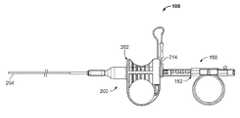
- FIG. 1illustrates an example of a tissue sampling device.
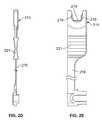
- FIGS. 2A and 2Billustrate a side and back view of a sheath device.
- FIG. 2Cillustrates a partial cross section of a distal end of a sheath of a sheath device.
- FIGS. 2D and 2Eillustrate side and front views of a removable or adjustable stop that engages a coring device.
- FIG. 3Ashows a variation of a coring device.
- FIG. 3Bis a cross sectional view of a coring handle of the coring device of FIG. 3A .
- FIG. 3Cshows a partial cross sectional view of a coring tip and shaft of the coring device of FIG. 3A .
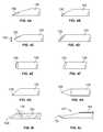
- FIGS. 4A to 4Jillustrate a number of variations of coring and needle tips for use with the devices described herein.
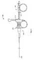
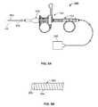
- FIG. 5Aillustrates a tissue sampling system including a tissue sampling device and a Doppler catheter with a Doppler processing unit.
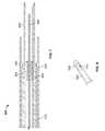
- FIG. 5Bshows a distal end of the Doppler catheter of FIG. 5A .
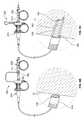
- FIG. 6Aillustrates the tissue sampling system being advanced through a scope and into lungs of a patient.
- FIGS. 6B to 6Dillustrate a variation of the tissue sampling device retrieving a core sample of tissue from the body.
- FIGS. 6E to 6Fillustrate a variation of the tissue sampling device comprising a stylet.
- FIG. 7illustrates another tissue sampling system including a sheath, needle and stylet and cooperating stop features.
- FIG. 8illustrates a partial view of another tissue sampling device including a sheath having a lateral opening.
- FIG. 1illustrates an example of a tissue sampling device 100 having a coring device 150 slidably coupled through a sheath device 200 .
- the coring device 150includes a coring handle 152 (also referred to as a coring hub) affixed to a shaft (not shown in FIG. 1 ), where the shaft extends through the sheath device 200 .
- the sheath device 200includes a sheath handle 202 (also referred to as a sheath hub) affixed to the sheath 204 (typically at a proximal end).
- the coring handle 152 and the sheath handle 202are slidably coupled to form a handle assembly of the tissue sampling device 100 .
- the coring handle 152is keyed or otherwise configured so the coring device 150 cannot rotate relative to the sheath 200 or sheath handle 202 .
- the features of the coring handle 152 and sheath handle 202provide an advantage when a user actuates the handle to drive the coring device 150 into tissue for capturing a sample of tissue while allowing for controlling the depth of penetration of the coring device 150 .
- Part of the mechanical advantageis that the use of the two handles to increase the velocity and or force at which the coring device contacts/enters tissue.
- the device 100also includes an adjustable stop 214 for limiting advancement of the coring device 150 and therefore controls the depth of penetration of the coring device.
- This mechanical advantageallows the device 100 to function similar to that of a biopsy gun using the biomechanics of the user's hand.
- This advantageallows the user to drive the coring device into tissue at a velocity that is greater than that of conventional devices that rely on hand-thrust catheter/sheath advancement to drive a cutting device.
- the tissue sampling devicecan also be deployed using a hand-thrust to drive the coring device.
- the devices described hereinalso allow for thrusting the coring device through a low fiction sheath as opposed to thrusting a needle/catheter through a high friction bronchoscope/endoscope seal.
- the ability to control or adjust the deployment length of the coring device 150provides an added measure of safety when performing a biopsy.
- limiting the stroke of the coring devicereduces the possibility that the coring device causes collateral damage to tissue or organs adjacent to the target site. For example, in the case of a tumor that is adjacent to another organ, limiting the stroke length can prevent the core device from travelling through the tumor and into the adjacent organ. In the case where the device is used in the lungs, limiting the stroke length of the core device also reduces the chance that the device will breach the lungs or pleural membrane. This also reduces the chance to inadvertently puncture blood vessels distal to the target tissue.
- FIG. 2Aillustrates an example of a sheath device 200 for use with a variation of a tissue sampling according to the present invention.
- the sheath device 200includes a sheath handle 202 affixed or otherwise coupled to a sheath 204 .
- the sheath handle 202 and sheath 204include a sheath lumen 206 extending therethrough (as shown in FIG. 2B , which shows a view of the handle 202 taken along the line 2 B- 2 B of FIG. 2A ).
- the sheath lumen 206allows for insertion of the coring device to the target site in tissue.
- the opening of the sheath lumen 206can be tapered or stepped to ease loading of the core device into the sheath handle 202 .
- the sheath 204can include one or more areas of increased strength to provide a stress relief or sleeve 208 to prevent kinking of the sheath 204 adjacent to the sheath handle 202 .
- FIG. 2Aalso shows the sheath handle 202 including one or more grip surfaces 210 212 .
- the grip surfaces 210 212allow a user to manipulate the sheath hub 202 with one or more fingers/digits.
- grip surface 210comprises a ring while grip surface 212 comprises a concave depression in the sheath hub 202 .
- Additional variations of the sheath hub 202include both grip surfaces comprising a ring or concave depression.
- FIG. 2Aalso illustrates the sheath hub 202 including an adjustable/removable stop or locking member 214 for the coring device.
- the variation shown in FIG. 2Ashows the adjustable stop member 214 as being attached to the sheath handle 202 via a flexible extension 216
- additional variations of the devicecan include one or more stop members 214 that are separate from the sheath handle 202 or separate from the tissue sampling device 100 entirely.
- FIG. 2Cillustrates a partial cross section of a distal end of the sheath 204 .
- the sheath 204comprises a sufficient flexibility so that the user can navigate the device to remote target sites or tortuous anatomy within the body. Accordingly, the sheath can have varying regions of flexibility (e.g., very flexible at a distal portion and relatively stiffer at a proximal portion).
- the sheath 204can be reinforced with a braid and/or coil to mitigate the coring device from penetrating the sheath. Sheath penetration may result in endoscopy equipment damage or an unsafe condition for the user or patient.
- the sheath 204includes a coil 218 located at or near a distal end.
- the sheath 204can also optionally include a second reinforcing coil or braid 220 along some or all of the proximal section.
- the interior lumen or channel of the sheathcan be designed as a low friction surface to reduce the drag on the core device as it advances through the sheath 204 . This reduced frictional interface can allow faster actuation of the core device when advanced through the sheath 204 .
- the sheath 204can include any number of features commonly associated with catheters and sheaths (e.g., radiopaque markers, depth measurement indicators, etc.).
- FIGS. 2D and 2Eshow respective side and front views of a variation of an adjustable stop member 214 for use with the devices described herein.
- the stop member 214can include a flexible extension or tether like member 216 so that it can be affixed to a sheath handle.
- the stop member 214includes a section that couples to the core device to limit advancement of a tip device. In this manner, the user can limit the depth of penetration of the core device within tissue. Naturally, this feature allows the user to limit the depth of penetration which may impact the axial length of the core sample being excised.
- the stop member 214can simply couple to the core device via a friction fit.
- the illustrated variationshows a stop member 214 having a plurality of keys 219 that removably nest with mating pockets or keyways on a core device.
- FIG. 3Aillustrates a variation of a coring device 150 similar to that shown in FIG. 1 .
- the coring device 150includes a shaft 154 having a coring tip 156 located at a distal end of the shaft 154 .
- the coring device 150also includes a coring handle or coring hub 152 affixed to the shaft 154 .
- the coring handle 152includes a grip 164 similar to that shown on the sheath handle 202 of FIG. 2A .
- the finger grip 164is not limited to the ring-type structure shown. Instead, any number of surfaces can be substituted in place of the ring.
- the grip 164should allow a user of the device to use a single hand to produce a forceful thrust so that the coring tip can penetrate and excise tissue.
- the lumen 162can have any number of tapered or conical sections.
- FIG. 3Aalso shows a variation of the coring device 150 that includes a plurality of recesses, pockets or keyways 180 which receive the adjustable stop (e.g., as shown in FIGS. 2D and 2E ).
- the recesses 180can be located along a length of the coring handle 152 , such that when the stop member is in one of the recesses, the stop member limits an advancement distance that the coring tip advances from the sheath. Therefore, a user of the device 100 can set the adjustable stop member in a desired location to control a length that the core tip 156 extends from the sheath.
- Such a featurelimits the penetration depth of the coring device 150 where the combination of the coring device 150 and sheath device 200 provides a tissue sampling device having multiple set penetration depths.
- FIG. 3Bis a partial cross sectional view of the coring device 150 of FIG. 3A .
- the recesses 180are arranged along a length of the coring handle 152 .
- the coring handle 152includes a left-most recess 184 to keep the coring tip 156 recessed within the sheath to prevent accidental damage to the user or equipment caused by the coring tip 156 .
- the coring handle 152can include any additional stop surfaces to prevent removal of the coring handle 152 from the sheath handle. Accordingly, in some variations, when the adjustable stop is located in the left-most recess 184 , the coring device 150 will be locked into place because the coring handle 152 or shaft 154 prevents further proximal movement of the coring device. (i.e., the coring device is prevented from proximal movement by the coring handle and prevented from moving in a distal direction because of the adjustable stop.)
- FIG. 3Balso shows an example of the plurality of recesses 180 being spaced along the coring handle 152 so as to provide incremental positions for the adjustable stop member. As noted above, this feature allows the user to control the depth of penetration of the coring device 150 into tissue.
- the coring handle 152can optionally be constructed with depth indicators 182 that correlate the position of the recess 180 with the length of extension of the coring tip 156 from the sheath. Although four positions are shown, any number of positions can be employed.
- FIG. 3Balso shows the tapered lumen from the proximal end to the distal end. The tapered section allows for the advancement of accessories through the coring handle and guides said accessories into the lumen of the shaft.
- FIG. 3Cshows a partial sectional view of the coring tip 156 located at a distal end of the shaft 154 .
- the shaft 154comprises a wound ribbon or coil 160 .
- the wound ribbon or coil 160will be sealed to permit aspiration through the shaft 154 .
- This ribbon/coil 160increases the flexibility of the shaft 154 as well as reduces the friction between the shaft 154 and the interior of the sheath.
- the ribbon/coil 160can be affixed to a tube or cannula 158 .
- the cannula 158can be selected to have a relatively short length (e.g., in one variation the length of the cannula was 5 mm, however, the length can be chosen to be smaller or larger depending upon the particular application).
- the lumen 162 of the cannula 158can be continuous through the ribbon/coil 160 .
- the core sample lengthshall be a function of the position of the adjustable stop.
- the core tip 156comprises a beveled tip that is sharpened about the perimeter of the cannula 158 .
- FIGS. 4A to 4Jillustrate a partial list of examples of cannula 158 that can be used with the coring device 150 as described herein.
- the cannula 158can comprise a coring tip 156 with a long or short bevel tip ( FIGS. 4A and 4B respectively).
- the coring tip 156can comprise an offset 159 V-point ( FIG. 4C ).
- the coring tip 156can comprise a J-point ( FIG. 4D ).
- the coring tip 156can be a straight conical or angled conical point FIG. 4E or 4 F.
- the tip 156can comprise a 45 degree needle point FIG. 4G or even a trocar point FIG. 4H (the latter being used when not obtaining a coring sample).
- FIG. 4Iillustrates an angled tip of a cannula 158 .
- FIG. 4Jillustrates a curved or beveled tip 156 at an end of a cannula 158 .
- This latter tip 156is similar to that of a lancet or septum penetrating needle.
- the curved tip 156angles towards a centerline 157 of the cannula 158 .
- Variations of the deviceinclude a curved tip that does not curve to the centerline or curves past the centerline. The curved tip reduces the chance that the coring tip 156 interferes or damages a wall of the sheath, and subsequently the bronchoscope or endoscope as the physician advances the needle.
- the cannulae 158 described hereincan be constructed of various materials commonly used in similar medical applications including, but not limited to stainless steel, Nitinol, metal alloy, etc.
- FIG. 5Aillustrates a variation of a tissue sampling device 100 when used as part of a tissue sampling system 250 .
- the tissue sampling system 250includes a variation of a coring device 150 extending through a sheath device 200 both as described above.
- the systemfurther allows for any number of medical devices to be delivered therethrough.
- a Doppler catheter 260can be delivered through the coring device 150 .
- any number of devicescan be delivered through the tissue sampling device 100 .
- the tissue sampling device 100can be used to deliver any number of devices that might be necessary or useful to scan or observe the area of tissue from which a core sample is desired.
- Such devicesinclude, but are not limited to: a temperature measuring device, an optical fiber, an aspiration catheter, cautery probes for cauterizing bleeders, argon plasma probes for surface ablation, cryotherapy catheters for ablation or sampling, cytology brushes for parenchymal brushings or other brushing after penetration, cautery snares for excision of nodes, guide wires, wires for placing electrical leads for various medical devices, stylets/trocars, biopsy forceps, brachytherapy seeds or seed delivery catheters, ultrasound probes, fiber scopes, guidewires, and fiducials or fiducial delivery catheters. Additionally, the lumen may be used to deliver medicine and drugs or to deliver and suction saline for bronchi-aveolar lavage.
- a Doppler catheteris useful to determine whether a blood vessel is present or absent in the area of tissue from which a core sample is desired.
- the coring device 150can be withdrawn so that the coring tip is recessed within the sheath 204 of the sheath device 200 .
- the Doppler catheter 260is freely advancable through the coring device 150 and can extend from a distal opening of the sheath 204 .
- the proximal end of the Doppler catheterextends back through the coring device 150 and can be coupled to a Doppler processing unit 262 that can provide audio and/or visual feedback to the user.
- This configurationpermits scanning of tissue directly adjacent to the sheath 204 so that the coring device 150 can obtain a core sample of tissue from an area of tissue that was directly examined using the Doppler catheter.
- Doppler catheterscan be obtained from Escalon Vascular Access Inc., New Berlin, Wis.
- Doppler cathetersare described in U.S. Pat. Nos. 6,749,606 issued Jun. 15, 2004; 7,022,088 issued Apr. 4, 2006; 7,422,563 issued Sep. 9, 2008; and 7,393,330 Jul. 1, 2008; U.S. Publication Nos.: US-2003-0130657-A1 filed Oct. 25, 2002; US-2005-0107783-A1 filed Dec. 17, 2004; US-2007-0255304-A1 filed Nov. 22, 2006. The entirety of each of which is incorporated by reference.
- FIG. 5Bshows a distal end of a variation of a Doppler catheter of FIG. 5A .
- the shaft of the Doppler catheter 260can comprise a ribbon or wire 264 wound or reinforced structure.
- the ribbon/wire 264 structureprovides sufficient flexibility and column strength so that the Doppler tip 266 can be advanced against tissue that is to be scanned.
- the Doppler tip 266can comprise a transducer or lens in acoustical communication with a transducer that transmits the Doppler signal in a direction parallel or essentially parallel to an axis of the Doppler catheter 260 (and therefore parallel to an axis of the coring device).
- Such a forward scanning designpermits scanning of tissue and structures directly within an intended path of the coring device.
- Other examples of ultrasound catheters that may be delivered through the needle coring deviceare endobronchial ultrasound (EBUS) catheters which allow direct visualization of structures below the surface of the airway wall.
- EBUSendobronchial ultrasound
- FIG. 6Aillustrates one example of a tissue sampling system 250 used to obtain a sample of tissue from a remote site within the airways of the lungs.
- the tissue sampling system 250can be used in a number of regions of the body where the target site is accessed through tortuous anatomy.
- the tissue sampling devicecan be advanced through a scope-type device 50 such as an endoscope (or a bronchoscope when used in the lungs).
- the scope 50can include an eyepiece or be coupled to a monitor 52 to allow a physician to remotely observe the target site.
- a physiciancan advance the scope 50 within the vicinity of (or to) the target region of tissue.
- a Doppler or EBUS catheter 260is advanced from the tissue sampling device 100 and scope 50 so that the physician can observe the Doppler tip 266 being advanced against tissue to ensure proper scanning of the region. Due to the tidal motion of the tissue, the scanning of tissue can include scanning of the target site as well as scanning of adjacent regions to ensure that no blood vessel (or other structure) is close to create the risk of puncturing of the vessel.
- the physiciancan scan to determine the presence or absence of a blood vessel. For example, the physician can use the Doppler device to confirm the presence of a blood vessel beneath the tissue so that a region of tissue can be chosen away from the vessel or that a particular structure to be sampled is below the airway surface so that the physician can accurately target that site.
- the physiciancan scan the site to confirm that a blood vessel is not within the range of the Doppler catheter, where the Doppler's range scanning range is pre-selected to cover the maximum stroke of the coring device from the sheath.
- the tissue sampling device 100 of the present disclosurecan be used with a basic introducer catheter or sheath and without any scope type device.
- the Doppler or EBUScan be advanced against tissue so that the tissue sampling device 100 can be placed against that region of tissue. This eliminates the need to reposition the device and risk that the device is placed over a different region of tissue.
- the Doppler catheter 260can be withdrawn through the proximal end of the tissue sampling device 100 .
- FIGS. 6B to 6Crepresents both the tissue sampling device 100 located outside of the body of the patient as well as a detailed view of the distal end of the device 100 .
- FIG. 6Billustrates a state of the device 100 where the Doppler or EBUS probe is removed from the tissue sampling device 100 and the sheath 204 is placed adjacent to the airway tissue 10 .
- the physicianmoves the adjustable stop 214 from the retracted coring position 184 to the desired location (typically using the incremental markings or depth indicators 182 ). As discussed herein, this adjustment sets the maximum depth that the core device 150 extends from the sheath device 200 .
- FIG. 6Cillustrates a state of the tissue sampling device 100 where the core device 150 is rapidly advanced relative to the sheath device 200 .
- the configuration of the handle or hubs on the core device 150 and sheath device 200allow for the cannula 158 of the core device 150 to move in a manner similar to that of a biopsy gun.
- the handlesallow for the biomechanics of the physician's/assistants' hand to move the core device 150 and cannula 158 at velocity significantly greater than that possible with a single hand thrust of the device with an extended needle (current common practice).
- the increased velocityimproves the ability of the core tip 156 and cannula 158 to penetrate into tissue to obtain a core sample 12 .
- the ergonomic design of the handleallows for a physician/assistant to use a single hand (freeing the other hand for manipulation of the scope, attaching vacuum to the device, or other equipment).
- the operatorsuch as the physician assistant or in some instances, the physician, places an index and middle finger on the sheath handle and a thumb in the core-handle.
- the movement of these digits together(or the thumb towards the index and middle finger) produces the mechanical advantage and drives the core device 150 forward (the reduced frictional interface between the core shaft and sheath also assist in actuation of the device).
- Obtaining a core sample in such a mannerhas been shown in the laboratory to produce a better yield than tissues obtained with standard biopsy devices, namely, TBNA type needles.
- the diameter of the cannularanged from 18 to 21 Gauge and allow for core sample sizes ranging from 1 to 20 mm.
- variations of the devicecan include alternative ranges.
- a variation of the system 250includes the use of a lockable or standard syringe 280 that can be coupled to a proximal end of the core device 150 such that a chamber 284 of the syringe 280 is in fluid communication with a lumen 162 of the core device 150 .
- a stop-cock 286can fluidly isolate the chamber 284 of the locking syringe 280 such that when a plunger 282 in the syringe 280 is drawn back, a vacuum or negative pressure forms in the chamber 284 .
- the order of attachment of the syringe 280 to the core device 150 and/or the drawing of a vacuumcan occur in any logical order in addition to that described herein.
- the plunger 282is locked or held in place to maintain the negative pressure.
- the stop-cock 286can fluidly couple the chamber 284 of the syringe 280 to the lumen 162 of the core device 150 .
- the negative pressure in the chamber 284draws a vacuum through the core device 150 and effectively separates or grabs the tissue sample 12 from the site. The physician can then remove the tissue sampling device 100 along with the tissue sample 12 from the body.
- kits configurationcan include any combination of the following components: a tissue sampling device as shown herein; a Doppler or other sensing device; a Doppler processing unit or monitor, a locking syringe; a stopcock; and instructions for use of the system to obtain a tissue core sample.
- FIG. 6 eshows a stylet 310 for use with the tissue sampling device.
- the stylet 310includes a proximal stylet hub 312 , an elongate shaft 320 a tube 323 , and a distal stylet tip 322 .
- Suitable stylet materials for the shaftinclude without limitation nitinol and stainless steel.
- Suitable materials for the tube 323include without limitation nylon, polyethylene, PEBAX, polyurethane, Nitinol, and other flexible materials.
- FIG. 6 fshows the stylet 310 advanced through the coring device 340 .
- the styletis advanced until stylet hub 312 makes contact with a corresponding mating connector on the coring device 340 .
- Examples of connectorsinclude luer lock connectors.
- stylet hub 312 and the mating connector of the coring device 340cooperatively engage to controllably advance the stylet relative to the needle.
- cooperative structuresare threads that allow an operator to advance the stylet relative to the needle in increments.
- detentsto allow incrementing the stylet forward in a controlled manner.
- the presence of the stylet in the tissue sampling deviceserves to make the shaft of the tissue sampling device stiffer. This is advantageous for penetrating relatively tough or stiff tissues such as, for example, the upper bronchial airway or tracheal wall.
- the present inventionmay include a suite of stylets with varying stiffnesses and flexibilities. For example, the user may decide to use the tissue sampling device without a stylet for locations deep in the periphery where great flexibility is required but significant stiffness is not. Alternatively, for a location in the proximal lung, near the main carina where the airway wall is toughest due to the presence of significant cartilage rings and tough tissue in between, the user may select the stiffest stylet with the least flexibility (assuming tight radiused bends are not required to access the target location) to provide the highest likelihood for penetrating the airway wall.
- Varying stylet stiffnessesis accomplished by varying the diameter and material properties of the stylet shaft.
- a polymer tube 323may be fitted around the stylet shaft to maintain a smooth fit between the stylet assembly and the needle bore.
- the polymer tube materialwill influence the stiffness and flexibility balance so different polymer materials are likely to be used for different stylet assemblies.
- the combination of stylet diameter and material plus the polymer materialwill be integrated to produce a variety of different stylet assemblies.
- stylet shaftsmay range from 0.015′′ to 0.038′′ for a 18 gage needle.
- stylet shaft sizesmay range from 0.010′′ to 0.020′′.
- a polymer sleevewill be added to minimize the gap between the needle bore and the stylet assembly.
- numerous combinations of stylet diameters and polymer sleevesmay be combined into different stylet assemblies to provide a great variety of tissue sampler stiffness and flexibility solutions.
- a histology coremay be obtained as described above including the option of adjusting the depth stop 350 , and applying vacuum or suction to facilitate collection of a core sample from the target.
- target tissuesinclude without limitation lymph nodes, lesions, or tumors.
- the tissue sampling deviceincludes a means to vary or adjust its stiffness.
- the stiffness of the deviceis adjusted by positioning one of a plurality of stylets in the shaft.
- Each stylethas a different flexibility ranging from flexible to stiff.
- a difference in stylet flexibilitymay arise from a number of stylet properties including material, size, shape, coatings, and manufacturing techniques.
- a first styletis selected having a first flexibility and is positioned within the coring needle to provide a first stiffness. In this manner, or by replacing the first stylet with a second stylet, the stiffness of the coring device is adjusted. Additionally, removal of the stylet increases the shaft flexibility. Consequently, this embodiment of the present invention provides a means to, selectively vary or adjust the flexibility of the tissue sampling device.
- Another use of the styletis to mechanically eject a core sample from the lumen of the needle.
- FIG. 7illustrates another tissue sampling device 400 including a sheath 410 , needle 420 , and stylet 430 .
- the sheath 410is shown including a sheath flat 440 . Once needle collar 442 of the needle contacts the sheath flat, the needle is prohibited from further advancement relative to the sheath.
- the needle and sheathmay be advanced together and the rigidity of tissue sampling device is increased by the presence of the sheath. This is desirable in certain applications where increased rigidity is needed such as, for example, penetration of the larger airways.
- the rigiditymay be further increased by the presence of stylet 430 .
- stylet 430is shown having a stylet collar 450 which prohibits stylet from advancing distally beyond needle flat 452 .
- the styletis advanced though the needle until stylet collar contacts the needle flat 452 .
- the end of the styletpreferably extends to the needle opening and preferably not beyond the needle opening. The components then move together such that the rigidity of the tissue sampling device is increased.
- the styletserves to prevent sampling of undesirable tissue such as, for example, the airway wall when the needle is being used to penetrate the airway wall.
- the styletmay also be used to clear the needle bore and to express a tissue sample.
- the depth that the needle extends from the sheath, and the depth that the stylet extends relative to the needleare controlled with the above described collars and flats.
- the maximum distancesare predetermined. In one embodiment, the maximum distance that the needle extends from the sheath ranges from 5 to 40 mm, and more preferably from 15 to 25 mm.
- the flats, collars and stopsmay be made in a wide variety of ways. For example, a flat or collar may be made using polymer or metal tubing, or a coil. The components may be bonded to the associated member by welding or adhesives.
- sheath 500may comprise a lateral or side window 510 or port which can be used with any of the shafts 520 or cannula tips described above.
- the side window 510is used in conjunction with suction to allow the user to draw tissue into the sheath, and then the cannula tip is driven forward to excise a core or sample. This facilitates obtaining samples from the side of the instrument when articulation may be difficult.
- the tissue sampling deviceincludes steering functionality.
- a pull wireextends along the sheath and is actuated to turn the sheath in a direction.
- the needleis then advanced from the sheath at the desired angle.
- the tissue sampling deviceincludes a guide wire lumen in addition to the working channel or lumen for the needle.
- the guidewire lumenmay be coaxially disposed relative to the needle lumen.
- the guidewireis advanced first to a target location or position and the tissue sampling device is advanced along the guidewire into the proper position.
- the guidewire itselfis preferably radiopaque.
- Nitonolis an example material for the guidewire.
- the guidewiremay additionally be equipped with an anchoring tip such that the guidewire may be actuated to anchor itself to a target site. To this end, a hook or balloon may be present at the tip of the guidewire to hold it to a tissue structure.
- the outside of the sheath of the coring needlemay be marked with any pattern of symbols, lines, or marks to help visualize the sheath.
- the devices of the present inventionare configured to obtain a core sample of tissue or a sample of tissue from a target site within a body of a patient.
- the deviceis discussed as being primarily used in the lungs, the device is not limited as such and it is contemplated that the invention has utility in other areas as well, specifically in applications in which blood vessels or other structures must be avoided while cutting or removing tissue.
Landscapes
- Health & Medical Sciences (AREA)
- Life Sciences & Earth Sciences (AREA)
- Surgery (AREA)
- Engineering & Computer Science (AREA)
- Heart & Thoracic Surgery (AREA)
- Biomedical Technology (AREA)
- Animal Behavior & Ethology (AREA)
- General Health & Medical Sciences (AREA)
- Public Health (AREA)
- Veterinary Medicine (AREA)
- Pathology (AREA)
- Medical Informatics (AREA)
- Molecular Biology (AREA)
- Nuclear Medicine, Radiotherapy & Molecular Imaging (AREA)
- Biophysics (AREA)
- Physics & Mathematics (AREA)
- Radiology & Medical Imaging (AREA)
- Hematology (AREA)
- Anesthesiology (AREA)
- Pulmonology (AREA)
- Optics & Photonics (AREA)
- Vascular Medicine (AREA)
- Otolaryngology (AREA)
- Biodiversity & Conservation Biology (AREA)
- Plasma & Fusion (AREA)
- Physiology (AREA)
- Endoscopes (AREA)
- Surgical Instruments (AREA)
Abstract
Description
Claims (10)
Priority Applications (4)
| Application Number | Priority Date | Filing Date | Title |
|---|---|---|---|
| US12/776,978US8517955B2 (en) | 2009-05-08 | 2010-05-10 | Tissue sampling devices, systems and methods |
| US13/965,886US9307960B2 (en) | 2009-05-08 | 2013-08-13 | Tissue sampling devices, systems and methods |
| US15/069,792US9907543B2 (en) | 2009-05-08 | 2016-03-14 | Tissue sampling devices, systems and methods |
| US15/878,164US10792022B2 (en) | 2009-05-08 | 2018-01-23 | Tissue sampling devices, systems and methods |
Applications Claiming Priority (3)
| Application Number | Priority Date | Filing Date | Title |
|---|---|---|---|
| US17685909P | 2009-05-08 | 2009-05-08 | |
| US22922609P | 2009-07-28 | 2009-07-28 | |
| US12/776,978US8517955B2 (en) | 2009-05-08 | 2010-05-10 | Tissue sampling devices, systems and methods |
Related Child Applications (1)
| Application Number | Title | Priority Date | Filing Date |
|---|---|---|---|
| US13/965,886ContinuationUS9307960B2 (en) | 2009-05-08 | 2013-08-13 | Tissue sampling devices, systems and methods |
Publications (2)
| Publication Number | Publication Date |
|---|---|
| US20100312141A1 US20100312141A1 (en) | 2010-12-09 |
| US8517955B2true US8517955B2 (en) | 2013-08-27 |
Family
ID=43301243
Family Applications (4)
| Application Number | Title | Priority Date | Filing Date |
|---|---|---|---|
| US12/776,978Active2031-07-09US8517955B2 (en) | 2009-05-08 | 2010-05-10 | Tissue sampling devices, systems and methods |
| US13/965,886Active2030-08-25US9307960B2 (en) | 2009-05-08 | 2013-08-13 | Tissue sampling devices, systems and methods |
| US15/069,792ActiveUS9907543B2 (en) | 2009-05-08 | 2016-03-14 | Tissue sampling devices, systems and methods |
| US15/878,164Active2031-05-01US10792022B2 (en) | 2009-05-08 | 2018-01-23 | Tissue sampling devices, systems and methods |
Family Applications After (3)
| Application Number | Title | Priority Date | Filing Date |
|---|---|---|---|
| US13/965,886Active2030-08-25US9307960B2 (en) | 2009-05-08 | 2013-08-13 | Tissue sampling devices, systems and methods |
| US15/069,792ActiveUS9907543B2 (en) | 2009-05-08 | 2016-03-14 | Tissue sampling devices, systems and methods |
| US15/878,164Active2031-05-01US10792022B2 (en) | 2009-05-08 | 2018-01-23 | Tissue sampling devices, systems and methods |
Country Status (1)
| Country | Link |
|---|---|
| US (4) | US8517955B2 (en) |
Cited By (26)
| Publication number | Priority date | Publication date | Assignee | Title |
|---|---|---|---|---|
| US8880151B1 (en)* | 2013-11-27 | 2014-11-04 | Clear Guide Medical, Llc | Surgical needle for a surgical system with optical recognition |
| US20160157839A1 (en)* | 2014-12-03 | 2016-06-09 | Boston Scientific Scimed, Inc. | Accessory device for eus-fna needle for guidewire passage |
| US9622720B2 (en) | 2013-11-27 | 2017-04-18 | Clear Guide Medical, Inc. | Ultrasound system with stereo image guidance or tracking |
| US9907543B2 (en)* | 2009-05-08 | 2018-03-06 | Broncus Medical Inc. | Tissue sampling devices, systems and methods |
| CN107898480A (en)* | 2017-12-12 | 2018-04-13 | 贵州省人民医院 | A kind of Direct Microsurgical sexual system for bone tissue aspiration biopsy |
| US9968338B2 (en) | 2012-11-21 | 2018-05-15 | C. R. Bard, Inc. | Core needle biopsy device |
| US10582914B2 (en) | 2016-01-15 | 2020-03-10 | Covidien Lp | Navigable endobronchial tool to access tissue outside a bronchus |
| US20200138460A1 (en)* | 2018-05-01 | 2020-05-07 | Imperative Care, Inc. | Devices and methods for removing obstructive material from an intravascular site |
| US10839509B2 (en) | 2015-07-10 | 2020-11-17 | 3Scan Inc. | Spatial multiplexing of histological stains |
| US10835711B2 (en) | 2016-02-24 | 2020-11-17 | Incept, Llc | Telescoping neurovascular catheter with enlargeable distal opening |
| US10939805B2 (en) | 2017-09-25 | 2021-03-09 | Broncus Medical Inc. | Medical appliance for controlling medical device through catheter sheath based on pneumatic action |
| US11065018B2 (en) | 2019-12-18 | 2021-07-20 | Imperative Care, Inc. | Methods and systems for advancing a catheter to a target site |
| US11134859B2 (en) | 2019-10-15 | 2021-10-05 | Imperative Care, Inc. | Systems and methods for multivariate stroke detection |
| US11207497B1 (en) | 2020-08-11 | 2021-12-28 | Imperative Care, Inc. | Catheter with enhanced tensile strength |
| US11224434B2 (en) | 2017-01-06 | 2022-01-18 | Incept, Llc | Thromboresistant coatings for aneurysm treatment devices |
| US11395665B2 (en) | 2018-05-01 | 2022-07-26 | Incept, Llc | Devices and methods for removing obstructive material, from an intravascular site |
| US11439799B2 (en) | 2019-12-18 | 2022-09-13 | Imperative Care, Inc. | Split dilator aspiration system |
| US11471582B2 (en) | 2018-07-06 | 2022-10-18 | Incept, Llc | Vacuum transfer tool for extendable catheter |
| US11517335B2 (en) | 2018-07-06 | 2022-12-06 | Incept, Llc | Sealed neurovascular extendable catheter |
| US11553935B2 (en) | 2019-12-18 | 2023-01-17 | Imperative Care, Inc. | Sterile field clot capture module for use in thrombectomy system |
| US11565082B2 (en) | 2020-03-10 | 2023-01-31 | Imperative Care, Inc. | Enhanced flexibility neurovascular catheter |
| US11766539B2 (en) | 2019-03-29 | 2023-09-26 | Incept, Llc | Enhanced flexibility neurovascular catheter |
| US12171917B1 (en) | 2024-01-08 | 2024-12-24 | Imperative Care, Inc. | Devices for blood capture and reintroduction during aspiration procedure |
| US12201506B2 (en) | 2019-12-18 | 2025-01-21 | Imperative Care, Inc. | Rotatable thrombus engagement tool |
| US12232838B2 (en) | 2021-08-12 | 2025-02-25 | Imperative Care, Inc. | Method of robotically performing a neurovascular procedure |
| USD1077996S1 (en) | 2021-10-18 | 2025-06-03 | Imperative Care, Inc. | Inline fluid filter |
Families Citing this family (202)
| Publication number | Priority date | Publication date | Assignee | Title |
|---|---|---|---|---|
| US8308682B2 (en) | 2003-07-18 | 2012-11-13 | Broncus Medical Inc. | Devices for maintaining patency of surgically created channels in tissue |
| DE202004021953U1 (en) | 2003-09-12 | 2013-06-19 | Vessix Vascular, Inc. | Selectable eccentric remodeling and / or ablation of atherosclerotic material |
| US8409167B2 (en) | 2004-07-19 | 2013-04-02 | Broncus Medical Inc | Devices for delivering substances through an extra-anatomic opening created in an airway |
| US9713730B2 (en) | 2004-09-10 | 2017-07-25 | Boston Scientific Scimed, Inc. | Apparatus and method for treatment of in-stent restenosis |
| US8396548B2 (en) | 2008-11-14 | 2013-03-12 | Vessix Vascular, Inc. | Selective drug delivery in a lumen |
| US8019435B2 (en) | 2006-05-02 | 2011-09-13 | Boston Scientific Scimed, Inc. | Control of arterial smooth muscle tone |
| EP2455036B1 (en) | 2006-10-18 | 2015-07-15 | Vessix Vascular, Inc. | Tuned RF energy and electrical tissue characterization for selective treatment of target tissues |
| EP2076198A4 (en) | 2006-10-18 | 2009-12-09 | Minnow Medical Inc | Inducing desirable temperature effects on body tissue |
| JP5559539B2 (en) | 2006-10-18 | 2014-07-23 | べシックス・バスキュラー・インコーポレイテッド | System that induces desirable temperature effects on body tissue |
| US12290277B2 (en) | 2007-01-02 | 2025-05-06 | Aquabeam, Llc | Tissue resection with pressure sensing |
| US9232959B2 (en) | 2007-01-02 | 2016-01-12 | Aquabeam, Llc | Multi fluid tissue resection methods and devices |
| ES2769535T3 (en) | 2008-03-06 | 2020-06-26 | Aquabeam Llc | Tissue ablation and cauterization with optical energy carried in a fluid stream |
| EP2355737B1 (en) | 2008-11-17 | 2021-08-11 | Boston Scientific Scimed, Inc. | Selective accumulation of energy without knowledge of tissue topography |
| WO2011126580A2 (en) | 2010-04-09 | 2011-10-13 | Minnow Medical, Inc. | Power generating and control apparatus for the treatment of tissue |
| US9192790B2 (en) | 2010-04-14 | 2015-11-24 | Boston Scientific Scimed, Inc. | Focused ultrasonic renal denervation |
| US8473067B2 (en) | 2010-06-11 | 2013-06-25 | Boston Scientific Scimed, Inc. | Renal denervation and stimulation employing wireless vascular energy transfer arrangement |
| US9592008B2 (en)* | 2010-07-01 | 2017-03-14 | Pulmonx Corporation | Devices and systems for lung treatment |
| US9408661B2 (en) | 2010-07-30 | 2016-08-09 | Patrick A. Haverkost | RF electrodes on multiple flexible wires for renal nerve ablation |
| US9358365B2 (en) | 2010-07-30 | 2016-06-07 | Boston Scientific Scimed, Inc. | Precision electrode movement control for renal nerve ablation |
| US9155589B2 (en) | 2010-07-30 | 2015-10-13 | Boston Scientific Scimed, Inc. | Sequential activation RF electrode set for renal nerve ablation |
| US9084609B2 (en) | 2010-07-30 | 2015-07-21 | Boston Scientific Scime, Inc. | Spiral balloon catheter for renal nerve ablation |
| US9463062B2 (en) | 2010-07-30 | 2016-10-11 | Boston Scientific Scimed, Inc. | Cooled conductive balloon RF catheter for renal nerve ablation |
| US9084610B2 (en) | 2010-10-21 | 2015-07-21 | Medtronic Ardian Luxembourg S.A.R.L. | Catheter apparatuses, systems, and methods for renal neuromodulation |
| US8974451B2 (en) | 2010-10-25 | 2015-03-10 | Boston Scientific Scimed, Inc. | Renal nerve ablation using conductive fluid jet and RF energy |
| US9220558B2 (en) | 2010-10-27 | 2015-12-29 | Boston Scientific Scimed, Inc. | RF renal denervation catheter with multiple independent electrodes |
| US9028485B2 (en) | 2010-11-15 | 2015-05-12 | Boston Scientific Scimed, Inc. | Self-expanding cooling electrode for renal nerve ablation |
| US9089350B2 (en) | 2010-11-16 | 2015-07-28 | Boston Scientific Scimed, Inc. | Renal denervation catheter with RF electrode and integral contrast dye injection arrangement |
| US9668811B2 (en) | 2010-11-16 | 2017-06-06 | Boston Scientific Scimed, Inc. | Minimally invasive access for renal nerve ablation |
| US9326751B2 (en) | 2010-11-17 | 2016-05-03 | Boston Scientific Scimed, Inc. | Catheter guidance of external energy for renal denervation |
| US9060761B2 (en) | 2010-11-18 | 2015-06-23 | Boston Scientific Scime, Inc. | Catheter-focused magnetic field induced renal nerve ablation |
| US9192435B2 (en) | 2010-11-22 | 2015-11-24 | Boston Scientific Scimed, Inc. | Renal denervation catheter with cooled RF electrode |
| US9023034B2 (en) | 2010-11-22 | 2015-05-05 | Boston Scientific Scimed, Inc. | Renal ablation electrode with force-activatable conduction apparatus |
| US20120157993A1 (en) | 2010-12-15 | 2012-06-21 | Jenson Mark L | Bipolar Off-Wall Electrode Device for Renal Nerve Ablation |
| US9220561B2 (en) | 2011-01-19 | 2015-12-29 | Boston Scientific Scimed, Inc. | Guide-compatible large-electrode catheter for renal nerve ablation with reduced arterial injury |
| US9060759B2 (en)* | 2011-03-31 | 2015-06-23 | Cook Medical Technologies Llc | Adjustable-throw biopsy needle |
| US8709034B2 (en) | 2011-05-13 | 2014-04-29 | Broncus Medical Inc. | Methods and devices for diagnosing, monitoring, or treating medical conditions through an opening through an airway wall |
| US9345532B2 (en) | 2011-05-13 | 2016-05-24 | Broncus Medical Inc. | Methods and devices for ablation of tissue |
| CN103813745B (en) | 2011-07-20 | 2016-06-29 | 波士顿科学西美德公司 | In order to visualize, be directed at and to melt transcutaneous device and the method for nerve |
| EP2734264B1 (en) | 2011-07-22 | 2018-11-21 | Boston Scientific Scimed, Inc. | Nerve modulation system with a nerve modulation element positionable in a helical guide |
| EP4101399B1 (en) | 2011-08-05 | 2025-04-09 | Route 92 Medical, Inc. | System for treatment of acute ischemic stroke |
| US10779855B2 (en) | 2011-08-05 | 2020-09-22 | Route 92 Medical, Inc. | Methods and systems for treatment of acute ischemic stroke |
| US8768435B2 (en) | 2011-09-07 | 2014-07-01 | Saint Louis University | Foreign body location and retrieval device |
| WO2013055826A1 (en) | 2011-10-10 | 2013-04-18 | Boston Scientific Scimed, Inc. | Medical devices including ablation electrodes |
| US9420955B2 (en) | 2011-10-11 | 2016-08-23 | Boston Scientific Scimed, Inc. | Intravascular temperature monitoring system and method |
| EP2765940B1 (en) | 2011-10-11 | 2015-08-26 | Boston Scientific Scimed, Inc. | Off-wall electrode device for nerve modulation |
| US9364284B2 (en) | 2011-10-12 | 2016-06-14 | Boston Scientific Scimed, Inc. | Method of making an off-wall spacer cage |
| CN104039236B (en) | 2011-10-15 | 2016-06-15 | 转化医药7有限责任公司 | Soft tissue core biopsy device and method |
| US9162046B2 (en) | 2011-10-18 | 2015-10-20 | Boston Scientific Scimed, Inc. | Deflectable medical devices |
| EP2768568B1 (en) | 2011-10-18 | 2020-05-06 | Boston Scientific Scimed, Inc. | Integrated crossing balloon catheter |
| US8951251B2 (en) | 2011-11-08 | 2015-02-10 | Boston Scientific Scimed, Inc. | Ostial renal nerve ablation |
| WO2013074813A1 (en) | 2011-11-15 | 2013-05-23 | Boston Scientific Scimed, Inc. | Device and methods for renal nerve modulation monitoring |
| US9119632B2 (en) | 2011-11-21 | 2015-09-01 | Boston Scientific Scimed, Inc. | Deflectable renal nerve ablation catheter |
| WO2013078235A1 (en) | 2011-11-23 | 2013-05-30 | Broncus Medical Inc | Methods and devices for diagnosing, monitoring, or treating medical conditions through an opening through an airway wall |
| US9265969B2 (en) | 2011-12-21 | 2016-02-23 | Cardiac Pacemakers, Inc. | Methods for modulating cell function |
| US9028472B2 (en) | 2011-12-23 | 2015-05-12 | Vessix Vascular, Inc. | Methods and apparatuses for remodeling tissue of or adjacent to a body passage |
| EP2797534A1 (en) | 2011-12-28 | 2014-11-05 | Boston Scientific Scimed, Inc. | Device and methods for nerve modulation using a novel ablation catheter with polymeric ablative elements |
| US9050106B2 (en) | 2011-12-29 | 2015-06-09 | Boston Scientific Scimed, Inc. | Off-wall electrode device and methods for nerve modulation |
| JP5379249B2 (en)* | 2012-01-13 | 2013-12-25 | 富士フイルム株式会社 | Tissue collection device |
| EP3351196A1 (en) | 2012-02-29 | 2018-07-25 | Procept Biorobotics Corporation | Automated image-guided tissue resection and treatment |
| US10660703B2 (en) | 2012-05-08 | 2020-05-26 | Boston Scientific Scimed, Inc. | Renal nerve modulation devices |
| US10321946B2 (en) | 2012-08-24 | 2019-06-18 | Boston Scientific Scimed, Inc. | Renal nerve modulation devices with weeping RF ablation balloons |
| CN104780859B (en) | 2012-09-17 | 2017-07-25 | 波士顿科学西美德公司 | Self-positioning electrode systems and methods for renal neuromodulation |
| US10549127B2 (en) | 2012-09-21 | 2020-02-04 | Boston Scientific Scimed, Inc. | Self-cooling ultrasound ablation catheter |
| US10398464B2 (en) | 2012-09-21 | 2019-09-03 | Boston Scientific Scimed, Inc. | System for nerve modulation and innocuous thermal gradient nerve block |
| CN104869930B (en) | 2012-10-10 | 2020-12-25 | 波士顿科学国际有限公司 | Renal neuromodulation apparatus and methods |
| US9044575B2 (en) | 2012-10-22 | 2015-06-02 | Medtronic Adrian Luxembourg S.a.r.l. | Catheters with enhanced flexibility and associated devices, systems, and methods |
| US10231867B2 (en) | 2013-01-18 | 2019-03-19 | Auris Health, Inc. | Method, apparatus and system for a water jet |
| USD735332S1 (en) | 2013-03-06 | 2015-07-28 | C. R. Bard, Inc. | Biopsy device |
| USD737440S1 (en) | 2013-03-07 | 2015-08-25 | C. R. Bard, Inc. | Biopsy device |
| WO2014143571A1 (en) | 2013-03-11 | 2014-09-18 | Boston Scientific Scimed, Inc. | Medical devices for modulating nerves |
| WO2014163987A1 (en) | 2013-03-11 | 2014-10-09 | Boston Scientific Scimed, Inc. | Medical devices for modulating nerves |
| US9808311B2 (en) | 2013-03-13 | 2017-11-07 | Boston Scientific Scimed, Inc. | Deflectable medical devices |
| US20140276051A1 (en)* | 2013-03-13 | 2014-09-18 | Gyrus ACM, Inc. (d.b.a Olympus Surgical Technologies America) | Device for Minimally Invasive Delivery of Treatment Substance |
| US10092276B2 (en) | 2013-03-15 | 2018-10-09 | Cook Medical Technologies Llc | Tissue acquisition device with indication system |
| US10265122B2 (en) | 2013-03-15 | 2019-04-23 | Boston Scientific Scimed, Inc. | Nerve ablation devices and related methods of use |
| US20150257785A1 (en)* | 2013-03-15 | 2015-09-17 | Shay Kent Seitz | Cuffed Fluid Line Extraction Device for Extraction of Tissue Ingrowth Cuffs and Fluid Lines from a Body and Associated Methods of Use |
| EP2967734B1 (en) | 2013-03-15 | 2019-05-15 | Boston Scientific Scimed, Inc. | Methods and apparatuses for remodeling tissue of or adjacent to a body passage |
| CN105228546B (en) | 2013-03-15 | 2017-11-14 | 波士顿科学国际有限公司 | Medical devices and methods for treating hypertension utilizing impedance compensation |
| EP2996754B1 (en) | 2013-05-18 | 2023-04-26 | Medtronic Ardian Luxembourg S.à.r.l. | Neuromodulation catheters with shafts for enhanced flexibility and control and associated devices and systems |
| US9463001B2 (en) | 2013-05-28 | 2016-10-11 | Transmed7, Llc | Soft tissue coring biopsy devices and methods |
| WO2014201165A1 (en) | 2013-06-11 | 2014-12-18 | Auris Surgical Robotics, Inc. | System for robotic assisted cataract surgery |
| CN105473092B (en) | 2013-06-21 | 2019-05-17 | 波士顿科学国际有限公司 | The medical instrument for renal nerve ablation with rotatable shaft |
| CN105473091B (en) | 2013-06-21 | 2020-01-21 | 波士顿科学国际有限公司 | Renal denervation balloon catheter with co-movable electrode supports |
| US9707036B2 (en) | 2013-06-25 | 2017-07-18 | Boston Scientific Scimed, Inc. | Devices and methods for nerve modulation using localized indifferent electrodes |
| USD735333S1 (en) | 2013-06-26 | 2015-07-28 | C. R. Bard, Inc. | Biopsy device |
| CN105358084B (en) | 2013-07-01 | 2018-11-09 | 波士顿科学国际有限公司 | Medical instrument for renal nerve ablation |
| US10413357B2 (en) | 2013-07-11 | 2019-09-17 | Boston Scientific Scimed, Inc. | Medical device with stretchable electrode assemblies |
| CN105377169B (en) | 2013-07-11 | 2019-04-19 | 波士顿科学国际有限公司 | Devices and methods for neuromodulation |
| US9925001B2 (en) | 2013-07-19 | 2018-03-27 | Boston Scientific Scimed, Inc. | Spiral bipolar electrode renal denervation balloon |
| US10342609B2 (en) | 2013-07-22 | 2019-07-09 | Boston Scientific Scimed, Inc. | Medical devices for renal nerve ablation |
| US10695124B2 (en) | 2013-07-22 | 2020-06-30 | Boston Scientific Scimed, Inc. | Renal nerve ablation catheter having twist balloon |
| US10426661B2 (en) | 2013-08-13 | 2019-10-01 | Auris Health, Inc. | Method and apparatus for laser assisted cataract surgery |
| CN105473093B (en) | 2013-08-22 | 2019-02-05 | 波士顿科学国际有限公司 | Flexible circuit with improved adhesion to renal neuromodulation balloon |
| US9155527B2 (en) | 2013-08-22 | 2015-10-13 | Transmed7, Llc | Soft tissue coring biopsy devices and methods |
| US9895194B2 (en) | 2013-09-04 | 2018-02-20 | Boston Scientific Scimed, Inc. | Radio frequency (RF) balloon catheter having flushing and cooling capability |
| EP3043719B1 (en) | 2013-09-12 | 2022-04-13 | Transmed7, LLC | Tissue coring biopsy devices |
| EP3043733A1 (en) | 2013-09-13 | 2016-07-20 | Boston Scientific Scimed, Inc. | Ablation balloon with vapor deposited cover layer |
| EP3049152B1 (en)* | 2013-09-19 | 2017-05-17 | Koninklijke Philips N.V. | High-dose rate brachytherapy system |
| US20150100062A1 (en)* | 2013-10-08 | 2015-04-09 | Boston Scientific Scimed, Inc. | Resection device having support elements and related methods of use |
| EP3057488B1 (en) | 2013-10-14 | 2018-05-16 | Boston Scientific Scimed, Inc. | High resolution cardiac mapping electrode array catheter |
| US11246654B2 (en) | 2013-10-14 | 2022-02-15 | Boston Scientific Scimed, Inc. | Flexible renal nerve ablation devices and related methods of use and manufacture |
| US9962223B2 (en) | 2013-10-15 | 2018-05-08 | Boston Scientific Scimed, Inc. | Medical device balloon |
| US9770606B2 (en) | 2013-10-15 | 2017-09-26 | Boston Scientific Scimed, Inc. | Ultrasound ablation catheter with cooling infusion and centering basket |
| EP3057521B1 (en) | 2013-10-18 | 2020-03-25 | Boston Scientific Scimed, Inc. | Balloon catheters with flexible conducting wires |
| CN105658163B (en) | 2013-10-25 | 2020-08-18 | 波士顿科学国际有限公司 | Embedded thermocouple in denervation flexible circuit |
| CN114366181B (en)* | 2013-12-13 | 2024-08-02 | 直观外科手术操作公司 | Telescopic biopsy needle |
| US9265512B2 (en) | 2013-12-23 | 2016-02-23 | Silk Road Medical, Inc. | Transcarotid neurovascular catheter |
| EP3091922B1 (en) | 2014-01-06 | 2018-10-17 | Boston Scientific Scimed, Inc. | Tear resistant flex circuit assembly |
| EP4253024B1 (en) | 2014-01-27 | 2025-02-26 | Medtronic Ireland Manufacturing Unlimited Company | Neuromodulation catheters having jacketed neuromodulation elements and related devices |
| US11000679B2 (en) | 2014-02-04 | 2021-05-11 | Boston Scientific Scimed, Inc. | Balloon protection and rewrapping devices and related methods of use |
| CN106572881B (en) | 2014-02-04 | 2019-07-26 | 波士顿科学国际有限公司 | Alternative placement of thermal sensors on bipolar electrodes |
| CN106232043B (en) | 2014-04-24 | 2019-07-23 | 美敦力阿迪安卢森堡有限公司 | Nerve modulation conduit and relevant system and method with braiding axle |
| CA2950805A1 (en)* | 2014-06-10 | 2015-12-17 | Charles WALTHER | Endoscopic biopsy instrument |
| US11020098B2 (en)* | 2014-09-09 | 2021-06-01 | Boston Scientific Scimed, Inc. | Methods, systems and devices for cryogenic biopsy |
| WO2016047202A1 (en)* | 2014-09-26 | 2016-03-31 | オリンパス株式会社 | Endoscope puncture needle |
| US10231750B2 (en) | 2014-09-29 | 2019-03-19 | Transmed7, Llc | Excisional device distal working end actuation mechanism and method |
| US10426497B2 (en) | 2015-07-24 | 2019-10-01 | Route 92 Medical, Inc. | Anchoring delivery system and methods |
| US11065019B1 (en) | 2015-02-04 | 2021-07-20 | Route 92 Medical, Inc. | Aspiration catheter systems and methods of use |
| CN119949953A (en) | 2015-02-04 | 2025-05-09 | 92号医疗公司 | Intravascular access system, dilator and system including dilator |
| WO2016138283A1 (en)* | 2015-02-26 | 2016-09-01 | Boston Scientific Scimed, Inc. | Adjustable throw percutaneous needle |
| US20160287223A1 (en)* | 2015-04-01 | 2016-10-06 | Boston Scientific Scimed, Inc. | Pulmonary biopsy devices |
| US20160287279A1 (en) | 2015-04-01 | 2016-10-06 | Auris Surgical Robotics, Inc. | Microsurgical tool for robotic applications |
| US10111715B2 (en)* | 2015-05-11 | 2018-10-30 | Veran Medical Technologies, Inc. | Adjustable length medical instrument assembly with localization elements for tracking medical instrument extension |
| US20160331343A1 (en) | 2015-05-11 | 2016-11-17 | Veran Medical Technologies, Inc. | Medical apparatus with translatable imaging device for real-time confirmation of interception of target tissue |
| JP6925282B2 (en)* | 2015-06-02 | 2021-08-25 | メリット・メディカル・システムズ・インコーポレイテッドMerit Medical Systems,Inc. | Tissue excision device |
| US20180153528A1 (en)* | 2015-06-04 | 2018-06-07 | University Of Florida Research Foundation, Inc. | Coaxial biopsy needles |
| US10575754B2 (en) | 2015-09-23 | 2020-03-03 | Covidien Lp | Catheter having a sensor and an extended working channel |
| DE202015105488U1 (en)* | 2015-10-16 | 2017-01-17 | M T W - Endoskopie W. Haag Kg | biopsy forceps |
| US9955986B2 (en) | 2015-10-30 | 2018-05-01 | Auris Surgical Robotics, Inc. | Basket apparatus |
| US9949749B2 (en) | 2015-10-30 | 2018-04-24 | Auris Surgical Robotics, Inc. | Object capture with a basket |
| US10231793B2 (en) | 2015-10-30 | 2019-03-19 | Auris Health, Inc. | Object removal through a percutaneous suction tube |
| US10856729B2 (en)* | 2016-02-29 | 2020-12-08 | Covidien Lp | Surgical system having a guide catheter including a fluid passageway |
| US10802695B2 (en) | 2016-03-23 | 2020-10-13 | Youar Inc. | Augmented reality for the internet of things |
| CA3021313A1 (en)* | 2016-04-17 | 2017-10-26 | Acantha Medical, Inc. | Device and method for single-handed access and insertion of an article |
| US11413433B2 (en) | 2016-04-17 | 2022-08-16 | Acantha Medical, LLC | Device and method for single-handed access and insertion of an article |
| WO2018063850A1 (en)* | 2016-09-27 | 2018-04-05 | Cook Medical Technologies Llc | Sample retrieval device and method of use thereof |
| AU2017339213A1 (en)* | 2016-10-07 | 2019-05-02 | Body Vision Medical Ltd | Devices for use in interventional and surgical procedures and methods of use thereof |
| US20180098756A1 (en)* | 2016-10-12 | 2018-04-12 | Covidien Lp | Biopsy system and method of use |
| US10575872B2 (en)* | 2016-10-14 | 2020-03-03 | Pacesetter, Inc. | Catheter-based system for delivery and retrieval of a leadless pacemaker |
| CN110392591B (en) | 2017-01-10 | 2022-06-03 | 92号医疗公司 | Aspiration catheter system and method of use |
| US10864350B2 (en) | 2017-01-20 | 2020-12-15 | Route 92 Medical, Inc. | Single operator intracranial medical device delivery systems and methods of use |
| US11529190B2 (en) | 2017-01-30 | 2022-12-20 | Covidien Lp | Enhanced ablation and visualization techniques for percutaneous surgical procedures |
| US11406365B2 (en)* | 2017-03-23 | 2022-08-09 | Gyrus Acmi, Inc. | Needle handle with vacuum chamber |
| CN108934160B (en)* | 2017-03-28 | 2021-08-31 | 奥瑞斯健康公司 | Shaft actuating handle |
| EP3606400B1 (en) | 2017-04-07 | 2022-03-09 | Auris Health, Inc. | Patient introducer alignment |
| US10285574B2 (en) | 2017-04-07 | 2019-05-14 | Auris Health, Inc. | Superelastic medical instrument |
| CN108814687B (en)* | 2018-04-27 | 2021-03-09 | 河南中医药大学 | Cell puncture needle for pathology examination |
| US10872449B2 (en) | 2018-05-02 | 2020-12-22 | Covidien Lp | System and method for constructing virtual radial ultrasound images from CT data and performing a surgical navigation procedure using virtual ultrasound images |
| JP7616642B2 (en) | 2018-05-17 | 2025-01-17 | ルート92メディカル・インコーポレイテッド | Suction catheter system and method of use |
| JP7267309B2 (en) | 2018-06-07 | 2023-05-01 | オーリス ヘルス インコーポレイテッド | Robotic medical system with high-strength instruments |
| JP7391886B2 (en) | 2018-06-28 | 2023-12-05 | オーリス ヘルス インコーポレイテッド | Medical system incorporating pulley sharing |
| CN112423823B (en) | 2018-07-19 | 2022-07-29 | 奥林巴斯株式会社 | Puncture needle |
| US11071591B2 (en) | 2018-07-26 | 2021-07-27 | Covidien Lp | Modeling a collapsed lung using CT data |
| WO2020036685A1 (en) | 2018-08-15 | 2020-02-20 | Auris Health, Inc. | Medical instruments for tissue cauterization |
| WO2020036686A1 (en) | 2018-08-17 | 2020-02-20 | Auris Health, Inc. | Bipolar medical instrument |
| CN112770689B (en) | 2018-09-26 | 2024-07-19 | 奥瑞斯健康公司 | Systems and instruments for suction and irrigation |
| US11576738B2 (en) | 2018-10-08 | 2023-02-14 | Auris Health, Inc. | Systems and instruments for tissue sealing |
| GB2579343A (en)* | 2018-11-02 | 2020-06-24 | Holmin Staffan | Device |
| CN109331261B (en)* | 2018-11-27 | 2024-05-03 | 李秋 | Deep negative pressure drainage flusher |
| CN109512471B (en)* | 2018-11-28 | 2021-08-06 | 陕西省肿瘤医院 | Marrow biopsy puncture sampling device |
| WO2020131529A1 (en) | 2018-12-20 | 2020-06-25 | Auris Health, Inc. | Shielding for wristed instruments |
| EP3883492B1 (en) | 2019-01-25 | 2025-05-21 | Auris Health, Inc. | Vessel sealer with heating capabilities |
| EP3908201B1 (en) | 2019-03-25 | 2024-04-24 | Auris Health, Inc. | Instruments for medical stapling |
| US11975157B2 (en) | 2019-04-12 | 2024-05-07 | Covidien Lp | Method of manufacturing an elongated catheter having multiple sensors for three-dimensional location of the catheter |
| CN110115599B (en)* | 2019-05-16 | 2021-09-24 | 声索生物科技(上海)有限公司 | Sheath tube assembly, ultrasonic probe and assembling method thereof |
| WO2020236691A1 (en)* | 2019-05-20 | 2020-11-26 | Innoblative Designs, Inc. | Minimally invasive assembly for lung ablation |
| CN114126529A (en) | 2019-06-25 | 2022-03-01 | 奥瑞斯健康公司 | Medical instrument including a wrist with hybrid redirecting surfaces |
| WO2020263629A1 (en) | 2019-06-27 | 2020-12-30 | Auris Health, Inc. | Systems and methods for a medical clip applier |
| WO2020263949A1 (en) | 2019-06-28 | 2020-12-30 | Auris Health, Inc. | Medical instruments including wrists with hybrid redirect surfaces |
| CN110339471A (en)* | 2019-07-08 | 2019-10-18 | 重庆医科大学 | A radiation-proof radiopharmaceutical rotation injection device |
| US20210219967A1 (en)* | 2019-07-16 | 2021-07-22 | Ethicon, Inc. | Systems, devices, and methods for coring tissue |
| US11896330B2 (en) | 2019-08-15 | 2024-02-13 | Auris Health, Inc. | Robotic medical system having multiple medical instruments |
| CN110477967A (en)* | 2019-09-18 | 2019-11-22 | 声索生物科技(上海)有限公司 | Biopsy ultrasound combination unit |
| WO2021059100A1 (en) | 2019-09-26 | 2021-04-01 | Auris Health, Inc. | Systems and methods for collision avoidance using object models |
| US10959792B1 (en) | 2019-09-26 | 2021-03-30 | Auris Health, Inc. | Systems and methods for collision detection and avoidance |
| US11737845B2 (en) | 2019-09-30 | 2023-08-29 | Auris Inc. | Medical instrument with a capstan |
| CN110522958A (en)* | 2019-09-30 | 2019-12-03 | 武汉中科科理光电技术有限公司 | Photo-electric intelligent syringe |
| US11737835B2 (en) | 2019-10-29 | 2023-08-29 | Auris Health, Inc. | Braid-reinforced insulation sheath |
| CN114727850A (en) | 2019-11-21 | 2022-07-08 | 奥瑞斯健康公司 | Systems and methods for draping surgical systems |
| CN110840493B (en)* | 2019-12-10 | 2022-09-30 | 上海澳华内镜股份有限公司 | Biopsy sampler instrument |
| CN114901188A (en) | 2019-12-31 | 2022-08-12 | 奥瑞斯健康公司 | Dynamic pulley system |
| EP4084724A4 (en) | 2019-12-31 | 2023-12-27 | Auris Health, Inc. | ADVANCED BASKET DRIVE MODE |
| US12370002B2 (en) | 2020-03-30 | 2025-07-29 | Auris Health, Inc. | Workspace optimization for robotic surgery |
| WO2021247130A1 (en)* | 2020-06-01 | 2021-12-09 | Biorasis Inc. | Needle-assisted automated insertion and extraction of implants |
| US12064191B2 (en) | 2020-06-03 | 2024-08-20 | Covidien Lp | Surgical tool navigation using sensor fusion |
| US11701492B2 (en) | 2020-06-04 | 2023-07-18 | Covidien Lp | Active distal tip drive |
| DE102020115846A1 (en) | 2020-06-16 | 2021-12-16 | InLine-Med GmbH | Biopsy needle device |
| CN115802975A (en) | 2020-06-29 | 2023-03-14 | 奥瑞斯健康公司 | System and method for detecting contact between a connecting rod and an external object |
| CN115734765A (en) | 2020-06-30 | 2023-03-03 | 奥瑞斯健康公司 | Robotic medical system with crash proximity indicator |
| US11357586B2 (en) | 2020-06-30 | 2022-06-14 | Auris Health, Inc. | Systems and methods for saturated robotic movement |
| US12256923B2 (en) | 2020-08-13 | 2025-03-25 | Covidien Lp | Endoluminal robotic systems and methods for suturing |
| US12383352B2 (en) | 2020-08-13 | 2025-08-12 | Covidien Lp | Endoluminal robotic (ELR) systems and methods |
| US12161309B2 (en) | 2020-09-24 | 2024-12-10 | Covidien Lp | Articulating mechanism for the laparoscopic ablation device for blunt dissection |
| WO2022076893A1 (en) | 2020-10-09 | 2022-04-14 | Route 92 Medical, Inc. | Aspiration catheter systems and methods of use |
| US20220257222A1 (en)* | 2021-02-17 | 2022-08-18 | American Endoscopic Innovations, LLC | System for Endoscopic Biopsy And Debulking |
| DE112022004581T5 (en) | 2021-10-22 | 2024-09-19 | Veran Medical Technologies, Inc. | LOW PROFILE ULTRASOUND CATHETER AND SYSTEM |
| CN114191001B (en)* | 2021-12-13 | 2023-12-19 | 苏州高分生物科技有限公司 | Tumor tissue sampling device and sampling method for tumor detection |
| US12303220B2 (en) | 2022-01-26 | 2025-05-20 | Covidien Lp | Autonomous endobronchial access with an EM guided catheter |
| US20230329605A1 (en)* | 2022-04-19 | 2023-10-19 | Becton, Dickinson And Company | Blood Draw Device with Catheter Length Adjustable Advancement Stop and Tube Position Indicator |
| CN114601554B (en)* | 2022-05-10 | 2022-08-12 | 上海导向医疗系统有限公司 | Ablation Needle and Ablation System |
| CN116058783B (en)* | 2023-02-24 | 2024-04-02 | 东莞市人民医院 | Swing-type anorectal endoscope and its use |
| CN118370561B (en)* | 2024-06-24 | 2024-09-03 | 山东第一医科大学附属肿瘤医院(山东省肿瘤防治研究院、山东省肿瘤医院) | Gynecological tumor sampling device |
Citations (4)
| Publication number | Priority date | Publication date | Assignee | Title |
|---|---|---|---|---|
| US5246011A (en)* | 1992-01-30 | 1993-09-21 | Caillouette James C | Fine needle aspiration syringe |
| US6749576B2 (en)* | 1996-01-26 | 2004-06-15 | Allegiance Corporation | Biopsy device with adjustable sampling |
| US7481775B2 (en)* | 2005-03-04 | 2009-01-27 | Ethicon Endo-Surgery, Inc. | Biopsy device incorporating an adjustable probe sleeve |
| US8337516B2 (en)* | 2007-10-22 | 2012-12-25 | Atheromed, Inc. | Atherectomy devices and methods |
Family Cites Families (5)
| Publication number | Priority date | Publication date | Assignee | Title |
|---|---|---|---|---|
| JP3607702B2 (en)* | 1993-05-17 | 2005-01-05 | ボストン・サイエンティフィック・コーポレーション | Multiple biopsy sampling equipment |
| WO2006058195A2 (en)* | 2004-11-23 | 2006-06-01 | Pneumrx, Inc. | Steerable device for accessing a target site and methods |
| US8840566B2 (en)* | 2007-04-02 | 2014-09-23 | University Of Washington | Catheter with imaging capability acts as guidewire for cannula tools |
| US8517955B2 (en) | 2009-05-08 | 2013-08-27 | Broncus Medical Inc. | Tissue sampling devices, systems and methods |
| US9307690B2 (en) | 2012-06-14 | 2016-04-12 | Dawn Equipment Company | Forged toothed wheel for a row crop planter |
- 2010
- 2010-05-10USUS12/776,978patent/US8517955B2/enactiveActive
- 2013
- 2013-08-13USUS13/965,886patent/US9307960B2/enactiveActive
- 2016
- 2016-03-14USUS15/069,792patent/US9907543B2/enactiveActive
- 2018
- 2018-01-23USUS15/878,164patent/US10792022B2/enactiveActive
Patent Citations (4)
| Publication number | Priority date | Publication date | Assignee | Title |
|---|---|---|---|---|
| US5246011A (en)* | 1992-01-30 | 1993-09-21 | Caillouette James C | Fine needle aspiration syringe |
| US6749576B2 (en)* | 1996-01-26 | 2004-06-15 | Allegiance Corporation | Biopsy device with adjustable sampling |
| US7481775B2 (en)* | 2005-03-04 | 2009-01-27 | Ethicon Endo-Surgery, Inc. | Biopsy device incorporating an adjustable probe sleeve |
| US8337516B2 (en)* | 2007-10-22 | 2012-12-25 | Atheromed, Inc. | Atherectomy devices and methods |
Cited By (53)
| Publication number | Priority date | Publication date | Assignee | Title |
|---|---|---|---|---|
| US10792022B2 (en) | 2009-05-08 | 2020-10-06 | Broncus Medical Inc. | Tissue sampling devices, systems and methods |
| US9907543B2 (en)* | 2009-05-08 | 2018-03-06 | Broncus Medical Inc. | Tissue sampling devices, systems and methods |
| US9968338B2 (en) | 2012-11-21 | 2018-05-15 | C. R. Bard, Inc. | Core needle biopsy device |
| US11013499B2 (en) | 2012-11-21 | 2021-05-25 | C. R. Bard, Inc. | Core needle biopsy device |
| US11793497B2 (en) | 2012-11-21 | 2023-10-24 | C.R. Bard, Inc. | Core needle biopsy device |
| US20150148668A1 (en)* | 2013-11-27 | 2015-05-28 | Clear Guide Medical, Llc | Surgical needle for a surgical system with optical recognition |
| US9622720B2 (en) | 2013-11-27 | 2017-04-18 | Clear Guide Medical, Inc. | Ultrasound system with stereo image guidance or tracking |
| US9668819B2 (en)* | 2013-11-27 | 2017-06-06 | Clear Guide Medical, Inc. | Surgical needle for a surgical system with optical recognition |
| US8880151B1 (en)* | 2013-11-27 | 2014-11-04 | Clear Guide Medical, Llc | Surgical needle for a surgical system with optical recognition |
| US20160157839A1 (en)* | 2014-12-03 | 2016-06-09 | Boston Scientific Scimed, Inc. | Accessory device for eus-fna needle for guidewire passage |
| US10149665B2 (en)* | 2014-12-03 | 2018-12-11 | Boston Scientific Scimed, Inc. | Accessory device for EUS-FNA needle for guidewire passage |
| US10839509B2 (en) | 2015-07-10 | 2020-11-17 | 3Scan Inc. | Spatial multiplexing of histological stains |
| US10582914B2 (en) | 2016-01-15 | 2020-03-10 | Covidien Lp | Navigable endobronchial tool to access tissue outside a bronchus |
| US11559290B2 (en) | 2016-01-15 | 2023-01-24 | Covidien Lp | Navigable endobronchial tool to access tissue outside a bronchus |
| US12343479B2 (en) | 2016-02-24 | 2025-07-01 | Incept, Llc | Neurovascular catheter |
| US11147949B2 (en) | 2016-02-24 | 2021-10-19 | Incept, Llc | Method of making an enhanced flexibility neurovascular catheter |
| US10835711B2 (en) | 2016-02-24 | 2020-11-17 | Incept, Llc | Telescoping neurovascular catheter with enlargeable distal opening |
| US11903588B2 (en) | 2017-01-06 | 2024-02-20 | Incept, Llc | Thromboresistant coatings for aneurysm treatment devices |
| US11224434B2 (en) | 2017-01-06 | 2022-01-18 | Incept, Llc | Thromboresistant coatings for aneurysm treatment devices |
| US11957308B2 (en) | 2017-09-25 | 2024-04-16 | Broncus Medical Inc. | Medical appliance for controlling medical device through catheter sheath based on pneumatic action |
| US10939805B2 (en) | 2017-09-25 | 2021-03-09 | Broncus Medical Inc. | Medical appliance for controlling medical device through catheter sheath based on pneumatic action |
| CN107898480B (en)* | 2017-12-12 | 2020-12-22 | 贵州省人民医院 | A Microscopic Direct Vision System for Bone Tissue Biopsy |
| CN107898480A (en)* | 2017-12-12 | 2018-04-13 | 贵州省人民医院 | A kind of Direct Microsurgical sexual system for bone tissue aspiration biopsy |
| US11311303B2 (en) | 2018-05-01 | 2022-04-26 | Incept, Llc | Enhanced flexibility neurovascular catheter with tensile support |
| US10835272B2 (en) | 2018-05-01 | 2020-11-17 | Incept, Llc | Devices and methods for removing obstructive material from an intravascular site |
| US20200138460A1 (en)* | 2018-05-01 | 2020-05-07 | Imperative Care, Inc. | Devices and methods for removing obstructive material from an intravascular site |
| US12042160B2 (en) | 2018-05-01 | 2024-07-23 | Incept, Llc | Catheter having angled tip |
| US11123090B2 (en) | 2018-05-01 | 2021-09-21 | Incept, Llc | Neurovascular catheter having atraumatic angled tip |
| US11395665B2 (en) | 2018-05-01 | 2022-07-26 | Incept, Llc | Devices and methods for removing obstructive material, from an intravascular site |
| US10653434B1 (en)* | 2018-05-01 | 2020-05-19 | Imperative Care, Inc. | Devices and methods for removing obstructive material from an intravascular site |
| US10786270B2 (en) | 2018-05-01 | 2020-09-29 | Imperative Care, Inc. | Neurovascular aspiration catheter with elliptical aspiration port |
| US11471582B2 (en) | 2018-07-06 | 2022-10-18 | Incept, Llc | Vacuum transfer tool for extendable catheter |
| US11517335B2 (en) | 2018-07-06 | 2022-12-06 | Incept, Llc | Sealed neurovascular extendable catheter |
| US11850349B2 (en) | 2018-07-06 | 2023-12-26 | Incept, Llc | Vacuum transfer tool for extendable catheter |
| US11766539B2 (en) | 2019-03-29 | 2023-09-26 | Incept, Llc | Enhanced flexibility neurovascular catheter |
| US12350443B2 (en) | 2019-03-29 | 2025-07-08 | Incept, Llc | Enhanced flexibility neurovascular catheter |
| US11134859B2 (en) | 2019-10-15 | 2021-10-05 | Imperative Care, Inc. | Systems and methods for multivariate stroke detection |
| US11504020B2 (en) | 2019-10-15 | 2022-11-22 | Imperative Care, Inc. | Systems and methods for multivariate stroke detection |
| US11633272B2 (en) | 2019-12-18 | 2023-04-25 | Imperative Care, Inc. | Manually rotatable thrombus engagement tool |
| US12201506B2 (en) | 2019-12-18 | 2025-01-21 | Imperative Care, Inc. | Rotatable thrombus engagement tool |
| US11553935B2 (en) | 2019-12-18 | 2023-01-17 | Imperative Care, Inc. | Sterile field clot capture module for use in thrombectomy system |
| US11819228B2 (en) | 2019-12-18 | 2023-11-21 | Imperative Care, Inc. | Methods and systems for treating a pulmonary embolism |
| US11638637B2 (en) | 2019-12-18 | 2023-05-02 | Imperative Care, Inc. | Method of removing embolic material with thrombus engagement tool |
| US11457936B2 (en) | 2019-12-18 | 2022-10-04 | Imperative Care, Inc. | Catheter system for treating thromboembolic disease |
| US11439799B2 (en) | 2019-12-18 | 2022-09-13 | Imperative Care, Inc. | Split dilator aspiration system |
| US11253277B2 (en) | 2019-12-18 | 2022-02-22 | Imperative Care, Inc. | Systems for accessing a central pulmonary artery |
| US11065018B2 (en) | 2019-12-18 | 2021-07-20 | Imperative Care, Inc. | Methods and systems for advancing a catheter to a target site |
| US11565082B2 (en) | 2020-03-10 | 2023-01-31 | Imperative Care, Inc. | Enhanced flexibility neurovascular catheter |
| US11207497B1 (en) | 2020-08-11 | 2021-12-28 | Imperative Care, Inc. | Catheter with enhanced tensile strength |
| US12232838B2 (en) | 2021-08-12 | 2025-02-25 | Imperative Care, Inc. | Method of robotically performing a neurovascular procedure |
| US12376928B2 (en) | 2021-08-12 | 2025-08-05 | Imperative Care, Inc. | Catheter drive system for supra-aortic access |
| USD1077996S1 (en) | 2021-10-18 | 2025-06-03 | Imperative Care, Inc. | Inline fluid filter |
| US12171917B1 (en) | 2024-01-08 | 2024-12-24 | Imperative Care, Inc. | Devices for blood capture and reintroduction during aspiration procedure |
Also Published As
| Publication number | Publication date |
|---|---|
| US20170007217A1 (en) | 2017-01-12 |
| US9907543B2 (en) | 2018-03-06 |
| US10792022B2 (en) | 2020-10-06 |
| US9307960B2 (en) | 2016-04-12 |
| US20100312141A1 (en) | 2010-12-09 |
| US20180153532A1 (en) | 2018-06-07 |
| US20130331734A1 (en) | 2013-12-12 |
Similar Documents
| Publication | Publication Date | Title |
|---|---|---|
| US10792022B2 (en) | Tissue sampling devices, systems and methods | |
| EP2982309B1 (en) | Exchangeable core biopsy needle | |
| US9986981B2 (en) | Endoscopic ultrasound-guided notched biopsy needle | |
| US9782153B2 (en) | Endoscopic biopsy needle with coil sheath | |
| US6673023B2 (en) | Micro-invasive breast biopsy device | |
| US20090204005A1 (en) | Puncture resistant catheter for sensing vessels and for creating passages in tissue | |
| AU2011238490B2 (en) | Endoscopic ultrasound-guided biopsy needle | |
| US20160000415A1 (en) | Multiple-tissue fna sampling | |
| US20240032901A1 (en) | Ramped biopsy needle device | |
| US20170245841A1 (en) | Systems and methods for improved tissue sampling | |
| WO2025074374A1 (en) | A needle for harvesting a tissue during biopsy |
Legal Events
| Date | Code | Title | Description |
|---|---|---|---|
| AS | Assignment | Owner name:BRONCUS TECHNOLOGIES, INC., CALIFORNIA Free format text:ASSIGNMENT OF ASSIGNORS INTEREST;ASSIGNORS:KEAST, THOMAS M.;WEISS, AARON M.;GWERDER, ERIC J.;AND OTHERS;SIGNING DATES FROM 20100608 TO 20100621;REEL/FRAME:024865/0162 | |
| AS | Assignment | Owner name:BRONCUS MEDICAL INC., CALIFORNIA Free format text:ASSIGNMENT OF ASSIGNORS INTEREST;ASSIGNOR:BRONCUS TECHNOLOGIES, INC.;REEL/FRAME:028943/0371 Effective date:20120608 | |
| STCF | Information on status: patent grant | Free format text:PATENTED CASE | |
| AS | Assignment | Owner name:AETHER CORPORATE LIMITED, CHINA Free format text:SECURITY AGREEMENT;ASSIGNOR:BRONCUS MEDICAL INC.;REEL/FRAME:031960/0567 Effective date:20140109 Owner name:TIP-BRONCUS LIMITED, HONG KONG Free format text:SECURITY AGREEMENT;ASSIGNOR:BRONCUS MEDICAL INC.;REEL/FRAME:031960/0567 Effective date:20140109 Owner name:DINOVA VENTURE PARTNERS LP II, L.P., CHINA Free format text:SECURITY AGREEMENT;ASSIGNOR:BRONCUS MEDICAL INC.;REEL/FRAME:031960/0567 Effective date:20140109 Owner name:LIFETECH SCIENTIFIC (HONG KONG) CO., LTD., CHINA Free format text:SECURITY AGREEMENT;ASSIGNOR:BRONCUS MEDICAL INC.;REEL/FRAME:031960/0567 Effective date:20140109 | |
| AS | Assignment | Owner name:BRONCUS MEDICAL INC., CALIFORNIA Free format text:RELEASE OF SECURITY INTEREST;ASSIGNORS:LIFETECH SCIENTIFIC (HONG KONG) CO., LTD.;DINOVA VENTURE PARTNERS LP II, L.P.;TIP-BRONCUS LIMITED;AND OTHERS;REEL/FRAME:033012/0784 Effective date:20140523 | |
| AS | Assignment | Owner name:SRONCUB TECHNOLOGIES, INC., CALIFORNIA Free format text:SECURITY INTEREST;ASSIGNORS:BRONCUS MEDICAL, INC.;BRONCUS HOLDING CORPORATION;REEL/FRAME:033085/0827 Effective date:20140523 | |
| FPAY | Fee payment | Year of fee payment:4 | |
| AS | Assignment | Owner name:SRONCUB, INC., CALIFORNIA Free format text:CORRECTIVE ASSIGNMENT TO CORRECT THE ASSIGNEE NAME/RECEIVING PARTY NAME PREVIOUSLY RECORDED ON REEL 033085 FRAME 0827. ASSIGNOR(S) HEREBY CONFIRMS THE SECURITY INTEREST;ASSIGNORS:BRONCUS MEDICAL, INC.;BRONCUS HOLDING CORPORATION;REEL/FRAME:042242/0408 Effective date:20170405 | |
| AS | Assignment | Owner name:BRONCUS MEDICAL INC., CALIFORNIA Free format text:RELEASE BY SECURED PARTY;ASSIGNOR:SRONCUB, INC.;REEL/FRAME:043949/0765 Effective date:20170911 | |
| FEPP | Fee payment procedure | Free format text:MAINTENANCE FEE REMINDER MAILED (ORIGINAL EVENT CODE: REM.); ENTITY STATUS OF PATENT OWNER: SMALL ENTITY | |
| FEPP | Fee payment procedure | Free format text:ENTITY STATUS SET TO UNDISCOUNTED (ORIGINAL EVENT CODE: BIG.); ENTITY STATUS OF PATENT OWNER: LARGE ENTITY Free format text:7.5 YR SURCHARGE - LATE PMT W/IN 6 MO, LARGE ENTITY (ORIGINAL EVENT CODE: M1555); ENTITY STATUS OF PATENT OWNER: LARGE ENTITY | |
| MAFP | Maintenance fee payment | Free format text:PAYMENT OF MAINTENANCE FEE, 8TH YEAR, LARGE ENTITY (ORIGINAL EVENT CODE: M1552); ENTITY STATUS OF PATENT OWNER: LARGE ENTITY Year of fee payment:8 | |
| MAFP | Maintenance fee payment | Free format text:PAYMENT OF MAINTENANCE FEE, 12TH YEAR, LARGE ENTITY (ORIGINAL EVENT CODE: M1553); ENTITY STATUS OF PATENT OWNER: LARGE ENTITY Year of fee payment:12 |