US8517907B2 - Expandable brachytherapy apparatus and methods for using them - Google Patents
Expandable brachytherapy apparatus and methods for using themDownload PDFInfo
- Publication number
- US8517907B2 US8517907B2US12/277,286US27728608AUS8517907B2US 8517907 B2US8517907 B2US 8517907B2US 27728608 AUS27728608 AUS 27728608AUS 8517907 B2US8517907 B2US 8517907B2
- Authority
- US
- United States
- Prior art keywords
- elongate members
- proximal
- distal
- hub
- tissue
- Prior art date
- Legal status (The legal status is an assumption and is not a legal conclusion. Google has not performed a legal analysis and makes no representation as to the accuracy of the status listed.)
- Active, expires
Links
- 238000002725brachytherapyMethods0.000titleclaimsabstractdescription82
- 238000000034methodMethods0.000titleclaimsdescription30
- 230000005855radiationEffects0.000claimsabstractdescription69
- 230000037361pathwayEffects0.000claimsabstractdescription17
- 238000011282treatmentMethods0.000claimsdescription42
- 230000007246mechanismEffects0.000claimsdescription10
- 230000013011matingEffects0.000claimsdescription8
- 230000000916dilatatory effectEffects0.000claimsdescription3
- 210000001519tissueAnatomy0.000description77
- 239000000463materialSubstances0.000description19
- 238000002560therapeutic procedureMethods0.000description17
- 210000000481breastAnatomy0.000description14
- 238000003466weldingMethods0.000description14
- 239000000853adhesiveSubstances0.000description13
- 230000001070adhesive effectEffects0.000description13
- 239000003550markerSubstances0.000description13
- 238000005452bendingMethods0.000description10
- 238000003384imaging methodMethods0.000description9
- 206010028980NeoplasmDiseases0.000description8
- 238000001125extrusionMethods0.000description7
- 230000000007visual effectEffects0.000description7
- 230000008901benefitEffects0.000description6
- 230000000694effectsEffects0.000description6
- 238000002513implantationMethods0.000description6
- 238000012544monitoring processMethods0.000description6
- 230000002285radioactive effectEffects0.000description6
- 230000004323axial lengthEffects0.000description5
- 230000001012protectorEffects0.000description5
- 239000011248coating agentSubstances0.000description4
- 238000000576coating methodMethods0.000description4
- 238000013507mappingMethods0.000description4
- 238000013508migrationMethods0.000description4
- 230000005012migrationEffects0.000description4
- 208000026310Breast neoplasmDiseases0.000description3
- KDLHZDBZIXYQEI-UHFFFAOYSA-NPalladiumChemical compound[Pd]KDLHZDBZIXYQEI-UHFFFAOYSA-N0.000description3
- 238000003780insertionMethods0.000description3
- 230000037431insertionEffects0.000description3
- 239000002184metalSubstances0.000description3
- 229910052751metalInorganic materials0.000description3
- 210000002307prostateAnatomy0.000description3
- 239000011800void materialSubstances0.000description3
- FAPWRFPIFSIZLT-UHFFFAOYSA-MSodium chlorideChemical compound[Na+].[Cl-]FAPWRFPIFSIZLT-UHFFFAOYSA-M0.000description2
- 239000002131composite materialSubstances0.000description2
- 238000012790confirmationMethods0.000description2
- 238000009826distributionMethods0.000description2
- -1e.g.Substances0.000description2
- 238000002594fluoroscopyMethods0.000description2
- 239000010931goldSubstances0.000description2
- GKOZUEZYRPOHIO-UHFFFAOYSA-Niridium atomChemical compound[Ir]GKOZUEZYRPOHIO-UHFFFAOYSA-N0.000description2
- 239000002991molded plasticSubstances0.000description2
- 229910001000nickel titaniumInorganic materials0.000description2
- HLXZNVUGXRDIFK-UHFFFAOYSA-Nnickel titaniumChemical compound[Ti].[Ti].[Ti].[Ti].[Ti].[Ti].[Ti].[Ti].[Ti].[Ti].[Ti].[Ni].[Ni].[Ni].[Ni].[Ni].[Ni].[Ni].[Ni].[Ni].[Ni].[Ni].[Ni].[Ni].[Ni]HLXZNVUGXRDIFK-UHFFFAOYSA-N0.000description2
- 230000008569processEffects0.000description2
- 238000001959radiotherapyMethods0.000description2
- 238000007789sealingMethods0.000description2
- 239000011780sodium chlorideSubstances0.000description2
- 229910001220stainless steelInorganic materials0.000description2
- 239000010935stainless steelSubstances0.000description2
- 230000001225therapeutic effectEffects0.000description2
- 239000010963304 stainless steelSubstances0.000description1
- ZCYVEMRRCGMTRW-UHFFFAOYSA-N7553-56-2Chemical compound[I]ZCYVEMRRCGMTRW-UHFFFAOYSA-N0.000description1
- 206010006187Breast cancerDiseases0.000description1
- 239000004677NylonSubstances0.000description1
- 240000007594Oryza sativaSpecies0.000description1
- 235000007164Oryza sativaNutrition0.000description1
- 208000000236Prostatic NeoplasmsDiseases0.000description1
- 229910000589SAE 304 stainless steelInorganic materials0.000description1
- 210000003484anatomyAnatomy0.000description1
- 239000011324beadSubstances0.000description1
- 238000005422blastingMethods0.000description1
- 201000011510cancerDiseases0.000description1
- 239000002775capsuleSubstances0.000description1
- 235000013339cerealsNutrition0.000description1
- 238000002591computed tomographyMethods0.000description1
- 230000008878couplingEffects0.000description1
- 238000010168coupling processMethods0.000description1
- 238000005859coupling reactionMethods0.000description1
- 238000002788crimpingMethods0.000description1
- 238000002224dissectionMethods0.000description1
- 238000007667floatingMethods0.000description1
- 239000004811fluoropolymerSubstances0.000description1
- 229920002313fluoropolymerPolymers0.000description1
- 210000004907glandAnatomy0.000description1
- 239000011521glassSubstances0.000description1
- PCHJSUWPFVWCPO-UHFFFAOYSA-NgoldChemical compound[Au]PCHJSUWPFVWCPO-UHFFFAOYSA-N0.000description1
- 229910052737goldInorganic materials0.000description1
- 239000007943implantSubstances0.000description1
- 230000003993interactionEffects0.000description1
- 229910052740iodineInorganic materials0.000description1
- 239000011630iodineSubstances0.000description1
- 229910052741iridiumInorganic materials0.000description1
- 229920003049isoprene rubberPolymers0.000description1
- 230000002045lasting effectEffects0.000description1
- 230000003902lesionEffects0.000description1
- 238000004519manufacturing processMethods0.000description1
- 239000011159matrix materialSubstances0.000description1
- 239000012528membraneSubstances0.000description1
- 239000007769metal materialSubstances0.000description1
- 238000012986modificationMethods0.000description1
- 230000004048modificationEffects0.000description1
- 238000000465mouldingMethods0.000description1
- 229920001778nylonPolymers0.000description1
- 229910052763palladiumInorganic materials0.000description1
- 239000004033plasticSubstances0.000description1
- 239000006223plastic coatingSubstances0.000description1
- 229920000642polymerPolymers0.000description1
- 201000001514prostate carcinomaDiseases0.000description1
- 230000000693radiobiological effectEffects0.000description1
- 210000000664rectumAnatomy0.000description1
- 230000002787reinforcementEffects0.000description1
- 239000011347resinSubstances0.000description1
- 229920005989resinPolymers0.000description1
- 235000009566riceNutrition0.000description1
- 239000002356single layerSubstances0.000description1
- 230000003068static effectEffects0.000description1
- 238000004381surface treatmentMethods0.000description1
- 229920002725thermoplastic elastomerPolymers0.000description1
- 238000012546transferMethods0.000description1
- 238000002604ultrasonographyMethods0.000description1
- 238000012285ultrasound imagingMethods0.000description1
- 210000003708urethraAnatomy0.000description1
Images


Classifications
- A—HUMAN NECESSITIES
- A61—MEDICAL OR VETERINARY SCIENCE; HYGIENE
- A61N—ELECTROTHERAPY; MAGNETOTHERAPY; RADIATION THERAPY; ULTRASOUND THERAPY
- A61N5/00—Radiation therapy
- A61N5/10—X-ray therapy; Gamma-ray therapy; Particle-irradiation therapy
- A61N5/1001—X-ray therapy; Gamma-ray therapy; Particle-irradiation therapy using radiation sources introduced into or applied onto the body; brachytherapy
- A61N5/1014—Intracavitary radiation therapy
- A61N5/1015—Treatment of resected cavities created by surgery, e.g. lumpectomy
- A—HUMAN NECESSITIES
- A61—MEDICAL OR VETERINARY SCIENCE; HYGIENE
- A61N—ELECTROTHERAPY; MAGNETOTHERAPY; RADIATION THERAPY; ULTRASOUND THERAPY
- A61N5/00—Radiation therapy
- A61N5/10—X-ray therapy; Gamma-ray therapy; Particle-irradiation therapy
- A61N5/1001—X-ray therapy; Gamma-ray therapy; Particle-irradiation therapy using radiation sources introduced into or applied onto the body; brachytherapy
- A61N5/1014—Intracavitary radiation therapy
- A61N2005/1018—Intracavitary radiation therapy with multiple channels for guiding radioactive sources
Definitions
- the present inventionrelates generally to apparatus, systems, and methods for providing brachytherapy to a human or other mammalian body, and more particularly to expandable apparatus for performing brachytherapy treatment within tissue, e.g., within breast tissue and/or within a body cavity, and to methods for performing brachytherapy using such apparatus.
- Brachytherapyis a type of radiation therapy used to treat malignant tumors, such as cancer of the breast or prostate.
- brachytherapyinvolves positioning a radiation source directly into target tissue, which may include a tumor and/or tissue surrounding a cavity or void, which may contain potentially cancerous cells (such as a cavity or void created by removing a tumor).
- Brachytherapyis often divided into two categories: high dose rate (HDR) and low dose rate (LDR) brachytherapy.
- HDRhigh dose rate
- LDRlow dose rate
- a high activity radiation sourceis placed into target tissue, often via a previously implanted catheter, for a short period of time, e.g., lasting from several seconds to a few minutes.
- LDR brachytherapyinvolves placing a low activity radiation source into the target tissue for a longer, sometimes indefinite, period of time.
- LDR brachytherapyutilizes lower activity radiation sources.
- the energy field of the LDR radiation sourceresults in a measured and localized dose of radiation delivered to target tissue, e.g., a tumor, gland, or other tissue surrounding a cavity or void.
- target tissuee.g., a tumor, gland, or other tissue surrounding a cavity or void.
- the energy fieldthereafter decays to avoid excessive exposure of nearby healthy tissue.
- LDR brachytherapymay provide various advantages. For example, for healthcare workers, exposure precautions for LDR brachytherapy may be less stringent than those for HDR brachytherapy. Also, there are radiobiological advantages of LDR brachytherapy over HDR brachytherapy (e.g., the dose rate effect), which may lead to better sparing of normal tissue during treatment. Moreover, for patients, the relatively longer implantation period associated with LDR brachytherapy may result in fewer visits to a healthcare facility over the course of radiation treatment, as compared to HDR brachytherapy where patients must return to the healthcare facility for each fraction of radiation delivered, which, for breast brachytherapy, may typically include eight to ten (8-10) fractions.
- radioactive isotopessuch as Palladium (Pd)-103, Iodine (I)-125, Gold (Au)-198, and Iridium (Ir)-192. While the size and shape of the isotopes may vary, they may be provided in a standardized size of cylindrically shaped capsules that are approximately the size of a grain of rice, e.g., about 0.8 millimeter in diameter and about 4.5 millimeters in length, and are often referred to as “seeds.”
- LDR seedsare often delivered through needles using a guide template.
- the guide templatemay include a matrix of holes that guide the longitudinal advancement of the needles to ensure their proper position relative to the target tissue. Once the needles are properly located in the target tissue, the seeds may be deposited along the longitudinal axis of each needle, after which the needles may be withdrawn.
- LDR seedsare typically left indwelling and free floating within the target tissue and are, therefore, susceptible to migration.
- LDR seedsare generally not considered removable or repositionable.
- LDR brachytherapymay also require careful dose distribution calculations and seed mapping before, and often during, seed implantation. Such calculation and mapping may allow effective radiation delivery to the target tissue volume, while minimizing radiation to surrounding healthy tissue (e.g., the urethra and rectum, for example, in prostate brachytherapy).
- healthy tissuee.g., the urethra and rectum, for example, in prostate brachytherapy.
- problemsmay exist, such as potentially significant variability in accuracy of seed placement among different clinicians.
- LDR brachytherapy techniquesmay require the radioactive seeds to be manipulated individually at the time of implantation, which may be a time-consuming process.
- conventional LDR delivery needlesare generally limited to delivering the seeds linearly (along a relatively straight line).
- numerous implantse.g., including about 50-100 seeds, as are common with prostate brachytherapy
- the present inventionis generally directed to apparatus, systems, and methods for delivering brachytherapy to a localized target tissue region. While potentially useful in treating most any area of the body, an exemplary application is treating breast tissue, e.g., breast tumors or lumpectomy cavities.
- the apparatusmay be used to place and remove a localized radiation source for both neoadjuvant and post-excisional treatment.
- a systemfor delivering one or more therapeutic elements (e.g., radiation sources) relative to a target tissue region.
- the radiation sourcesmay be either immediately withdrawn (e.g., in HDR applications), or left in place, e.g., implanted, for a defined period of time (e.g., in LDR applications). In either instance, the radiation sources may deliver therapy to the target tissue region in accordance with a predefined therapy profile.
- LDR radiation sourcesmay be implanted and secured to the body or target tissue in such a way as to prevent or substantially limit movement of the sources relative to the target tissue.
- the apparatus and methods described hereinmay facilitate indwelling therapy using pre-arranged packages of radioactive sources, e.g., seeds, but also allow easy removal of the radiation sources upon completing brachytherapy treatment.
- radiation sourceand “radioactive source” may include any therapeutic element operable to deliver a dose of radiation.
- the radiation sourcemay be one or more radioactive seeds or, alternatively, one or more LDR or HDR wire elements (e.g., Iridium wire), e.g., as disclosed in the applications incorporated by reference elsewhere herein.
- LDR or HDR wire elementse.g., Iridium wire
- implantableindicates the capability of a device to be inserted into the body and then maintained in a relatively fixed or static position within the surrounding tissue for an extended period of time, e.g., an hour or more and/or several hours or more, including several days or more.
- target tissuemay include any portion of a human (or other mammalian) body that has been identified to benefit from radiation therapy.
- the target tissue regionmay be a tumor or lesion itself, tissue proximate or surrounding the tumor, or a cavity region created by tumor excision (such as the surrounding tissue or cavity associated with a lumpectomy cavity of the breast).
- the apparatus, systems, and methods described hereinmay be used for LDR or HDR brachytherapy, as described elsewhere herein and in the applications incorporated by reference herein. Moreover, while described herein with respect to brachytherapy, the apparatus, systems, and methods may apply to other therapy regimens that benefit from the removable implantation of therapy-delivering elements. In an exemplary application, the apparatus, systems, and methods are described herein for treating breast cancer. However, it will be appreciated that the apparatus, systems, and methods described herein may be used for treating other cancers or conditions that may benefit from brachytherapy treatment.
- a brachytherapy treatment apparatusin accordance with one embodiment, includes an elongate body including a proximal end and a distal end sized for introduction into a tract through tissue.
- a plurality of elongate membersmay be provided on the distal end including pathways for receiving a source of radiation therealong, the elongate members being movable from a collapsed configuration for introduction through a tissue tract to a target location, and an expanded configuration.
- a source of radiationmay be introduceable along the pathways for delivering radiation to the target location.
- a method for brachytherapy treatment of tissue within a bodythat includes creating a tract through tissue to a target location comprising a cavity, and advancing an elongate body carrying a plurality of elongate members through the tract into the target location with the elongate members in a collapsed configuration.
- the elongate membersmay be directed to an expanded configuration at the target location to position the elongate members away from a central axis such that tissue in the target region (e.g., surrounding the cavity) extends between at least a portion of adjacent elongate members, and radiation may be delivered to the target location to treat tissue at the target location.
- a system for brachytherapy treatment of tissue adjacent a cavity within a bodyincludes an expandable brachytherapy apparatus and a prep catheter including a proximal end, a distal end sized for introduction through a tissue tract into a body cavity, and an expandable member on the distal end for dilating tissue surrounding the body cavity before introducing the apparatus therein.
- a method for brachytherapy treatment of tissueincludes creating a tract through tissue to a target location adjacent to a cavity; introducing a distal end of a prep catheter through the tract into the cavity;
- a brachytherapy apparatusmay be introduced through the tract into the dilated cavity for delivering radiation.
- elongate members on the brachytherapy apparatusmay be directed to an expanded configuration at the target location to position the elongate members away from a central axis; and radiation may be delivered to the target location to treat tissue at the target location.
- a system for brachytherapy treatment of tissue adjacent a cavity within a bodyincludes a brachytherapy apparatus and an introducer sheath including a proximal end, a distal end sized for introduction through a tissue tract into a body cavity, and defining a lumen therebetween sized for receiving the apparatus therein in the collapsed configuration.
- the sheathmay include a slit extending at least partially between the proximal and distal ends to facilitate removal of the sheath from around the apparatus after introducing the apparatus through the sheath into the body cavity.
- a method for brachytherapy treatment of tissueincludes creating a tract through tissue to a target location adjacent to a cavity; introducing a distal end of an introducer sheath through the tract into the cavity; advancing a brachytherapy apparatus through the sheath; and removing the sheath from around the brachytherapy apparatus.
- an apparatus for brachytherapy treatment of tissueincludes an introducer sheath and a trocar removably disposed within the sheath.
- the sheathincludes a proximal end, a distal end sized for introduction through a tissue tract into a body cavity, and a lumen extending therebetween sized for receiving a brachytherapy apparatus therein.
- the sheathmay include a slit extending at least partially between the proximal and distal ends to facilitate removal of the sheath from around a radiation apparatus introduced into the lumen of the sheath.
- a brachytherapy treatment apparatusin accordance with yet another embodiment, includes an elongate body including a proximal end and a distal end configured for introduction into a tract through tissue; a plurality of elongate members on the distal end comprising pathways for receiving a source of radiation therealong, the elongate members being movable from a collapsed configuration for introduction through a tissue tract to a target location, and an expanded configuration; and a plurality of inserts including proximal ends and distal ends removably receivable along the pathways of respective elongate members.
- the insertsmay include malleable material allowing the inserts to be bent to bend and maintain proximal ends of the elongate members in a desired shape.
- the insertsmay include on the proximal ends of the inserts for engaging proximal ends of the elongate members when the inserts are received within the lumens to substantially seal the lumens.
- a method for brachytherapy treatment of tissue within a patient's bodythat includes creating a tract through tissue to a target location adjacent to a cavity; advancing an elongate body carrying a plurality of elongate members through the tract into the target location with the elongate members in a collapsed configuration; introducing inserts into the elongate members; and bending portions of the elongate members that extend from the patient's body, the inserts being malleably bent to hold the portions of the elongate members in a desired shape.
- the portions of the elongate membersmay be bent to place the portions adjacent the patient's skin between radiation treatments.
- a brachytherapy treatment apparatusin accordance with yet another embodiment, includes an elongate core member comprising a proximal end and a distal end and defining a longitudinal axis between the proximal and distal ends, a guide member on the core member disposed between the proximal and distal ends, a distal hub coupled to the distal end of the core member, a proximal hub on the proximal end of the core member, at least one of the proximal hub and the distal hub movable axially relative to the other of the proximal hub and the distal hub, and a plurality of elongate members coupled to the proximal and distal hubs.
- the elongate membersmay include pathways for receiving a source of radiation therealong.
- the elongate membersmay be movable between a collapsed configuration wherein intermediate regions of the elongate members contact the guide member for introduction through a tissue tract to a target location, and an expanded configuration, the intermediate regions moving radially outwardly as the elongate members are directed towards the expanded configuration.
- the elongate membersmay be received in recesses in the guide member in the collapsed configuration.
- the elongate membersmay contact the guide member such that the elongate members do not extend substantially parallel to the longitudinal axis in the collapsed configuration.
- the elongate membersmay be received in recesses in the guide member in the collapsed configuration such that the elongate members are arched in the collapsed configuration.
- the recessesmay include side walls, e.g., that prevent substantial lateral motion of the catheters while the intermediate regions are received in the recesses.
- a method for brachytherapy treatment of tissue within a bodye.g., where a tract extends through tissue to a target location adjacent to a cavity.
- a distal portion of an elongate bodymay be advanced through the tract into the target location with the distal portion in a collapsed configuration.
- the distal portionmay include a plurality of elongate members disposed around an elongate core member with intermediate regions of the elongate members contacting a guide member on the core member in the collapsed configuration.
- the elongate membersmay be received in respective recesses in the guide member or may simply contact an outer surface of the guide member. The recesses may prevent substantial lateral movement of the elongate members, e.g., during initial expansion.
- the distal portionmay be directed to an expanded configuration at the target location wherein the elongate members expand away from a central axis and the guide member, and radiation may be delivered to the target location via the distal portion to treat tissue at the target location.
- the elongate membersmay be arched in the collapsed configuration and may arch further in the expanded configuration. Such arching may resist substantial lateral movement of the elongate members, e.g., during initial expansion.
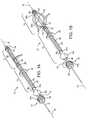
- FIGS. 1A and 1Bare perspective views of an exemplary embodiment of a brachytherapy apparatus including an expandable therapy delivery portion in collapsed and expanded configurations, respectively.
- FIG. 2Ais a cross-sectional side view of the apparatus of FIGS. 1A and 1B .
- FIG. 2Bis a detail of a distal tip of the apparatus of FIG. 2A .
- FIG. 2Cis a detail of an internal actuation mechanism within the apparatus of FIG. 2A .
- FIG. 3Ais another cross-sectional side view of the apparatus of FIGS. 1A and 1B .
- FIGS. 3B-3Dare details of the apparatus of FIG. 3A , showing break-away locations to provide a bail-out mechanism for the apparatus.
- FIGS. 3E and 3Fare details of the apparatus of FIGS. 1A and 1B , showing an actuation mechanism within the apparatus that provides audible feedback to a user when the apparatus is expanded.
- FIGS. 3G and 3Hare details of a proximal end of the apparatus of FIGS. 1A and 1B , showing markers on a central catheter that provide visual feedback to a user when the apparatus is expanded.
- FIG. 4Ais a side view of an alternative embodiment of a brachytherapy apparatus generally similar to the apparatus of FIGS. 1A and 1B , including bendable proximal regions on catheter tubes of the apparatus.
- FIG. 4Bis a side view of another alternative embodiment of a brachytherapy apparatus, including bendable proximal regions on catheter tubes of the apparatus.
- FIG. 4Cis a perspective view of yet another alternative embodiment of a brachytherapy apparatus, including bendable proximal regions on catheter tubes of the apparatus.
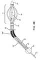
- FIG. 4Dis a perspective view of still another alternative embodiment of a brachytherapy apparatus, including a clamp applied on a proximal portion of the apparatus for bending the proximal portion.
- FIGS. 5A and 5Bare side views of the apparatus of FIGS. 1A and 1B , respectively.
- FIG. 5Cis a cross-sectional view of the apparatus of FIG. 5B , taken along line 5 C- 5 C.
- FIGS. 6A and 6Bare side views of a variation of the apparatus of FIGS. 1A and 1B , respectively.
- FIGS. 6C and 6Dare details of the apparatus of FIGS. 6A and 6B , showing internal threads within the apparatus for expanding and collapsing the apparatus.
- FIG. 7Ais a perspective view of an array of expanded struts and hubs that may be provided on a therapy delivery portion of a brachytherapy apparatus, such as that shown in FIGS. 1A and 1B .
- FIG. 7Bis a side view of the struts and hubs of FIG. 7A .
- FIG. 7Cis a cross-section of the struts of FIG. 7A and 7B , taken along line 7 C- 7 C.
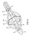
- FIG. 8is a perspective view of an alternative embodiment of an expandable therapy delivery portion of a brachytherapy apparatus including a support structure for providing a desired spacing of catheter tubes when the apparatus is expanded.
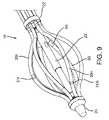
- FIG. 9is a perspective view of another alternative embodiment of an expandable therapy delivery portion of a brachytherapy apparatus including a plurality of markers on catheter tubes for monitoring the apparatus after implantation using external imaging.
- FIG. 10Ais a perspective view of another embodiment of an expandable therapy delivery portion of a brachytherapy apparatus including heat shrink tubing around catheter tubes and supports to achieve a desired radius of curvature of the catheter tubes when the apparatus is expanded.
- FIG. 10Bis a perspective view of still another embodiment of an expandable therapy delivery portion of a brachytherapy apparatus including multiple lengths of heat shrink tubing around catheter tubes and struts configured to achieve a desired radius of curvature of the catheter tubes when the apparatus is expanded.
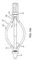
- FIG. 11is a side view of a balloon catheter for preparing a body cavity before delivering brachytherapy.
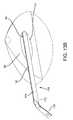
- FIG. 12is a perspective view of an introducer sheath for facilitating introduction of a brachytherapy apparatus into a body cavity, carried on an obturator.
- FIGS. 13A-13Fshow a method for introducing a brachytherapy apparatus into a lumpectomy cavity of a breast using the introducer sheath of FIG. 12 .
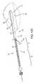
- FIG. 14Ais a cross-sectional side view of a catheter protector insert that may be introduced into an individual catheter of a brachytherapy apparatus.
- FIGS. 14B and 14Care details of the catheter protector insert of FIG. 14A .
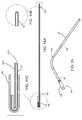
- FIG. 15is a perspective view of a catheter of a brachytherapy apparatus having the catheter protector insert of FIG. 14A received therein.
- FIG. 16Ais a perspective view of another exemplary embodiment of a brachytherapy apparatus including an expandable therapy delivery portion in a collapsed configuration.
- FIG. 16Bis a side view of the apparatus of FIG. 16A .
- FIG. 16Cis a cross-section of the apparatus of FIGS. 16A and 16B taken along line 16 C- 16 C of FIG. 16B .
- FIG. 16Dis a detail of a catheter guide of the apparatus of FIG. 16A .
- FIG. 17Ais a perspective view of the brachytherapy apparatus of FIG. 16A , showing the expandable therapy delivery portion in a partially expanded configuration.
- FIG. 17Bis a side view of the apparatus of FIG. 17A .
- FIG. 17Cis a cross-section of the apparatus of FIGS. 17A and 17B taken along line 17 C- 17 C of FIG. 17B .
- FIG. 17Dis a detail of the catheter guide of the apparatus of FIG. 17A .
- FIG. 18Ais a perspective view of the brachytherapy apparatus of FIGS. 16A and 17A , showing the expandable therapy delivery portion in a fully expanded configuration.
- FIG. 18Bis a side view of the apparatus of FIG. 18A .
- FIG. 18Cis a cross-section of the apparatus of FIGS. 18A and 18B taken along line 18 C- 18 C of FIG. 18B .
- FIG. 18Dis a detail of the catheter guide of the apparatus of FIG. 18A .
- FIGS. 1A and 1Bshow an exemplary embodiment of an expandable brachytherapy apparatus 10 that includes a proximal or tail portion 12 , and a distal or therapy delivery portion 14 , generally defining a longitudinal axis 16 extending therebetween.
- the distal portion 14may be deployed within a target location of a patient's body, e.g., a tumor or cavity within a breast or other body structure (not shown), and the proximal portion 12 may extend from the distal portion 14 , e.g., such that the proximal portion 12 protrudes at least partially outside of the body structure.
- the distal portion 14may be movable between a collapsed configuration, as shown in FIG.
- FIGS. 1B and 2Ae.g., for introduction through a tissue tract to a target location, and a fully deployed or expanded configuration, as shown in FIGS. 1B and 2A , e.g., for providing a three dimensional array of pathways at the target location, as described further below.
- the apparatus 10may include an expansion tool 70 , which may be coupled to the apparatus 10 for expanding and/or collapsing the distal portion 14 , as described further below.
- the expansion tool 70may be detachable from the apparatus 10 or may be permanently attached to the apparatus 10 (not shown).
- the apparatus 10may include one or more other components, e.g., a sheath or other cover (not shown), which may overly at least the therapy delivery portion 14 , e.g., until deployment.
- the apparatus 10may be part of a system, e.g., including a tubular delivery device, such as a catheter, cannula, trocar, obturator, and/or needle (also not shown), for introducing the apparatus 10 into a target location, e.g., as described in the applications incorporated by reference elsewhere herein.
- a tubular delivery devicesuch as a catheter, cannula, trocar, obturator, and/or needle (also not shown), for introducing the apparatus 10 into a target location, e.g., as described in the applications incorporated by reference elsewhere herein.
- a systemmay include an introducer sheath 110 and/or trocar 120 , such as that shown in FIG. 12 and described further below.
- the apparatus 10may include a sharpened distal tip (not shown), e.g., to facilitate advancement directly through tissue, also as disclosed in the applications incorporated by reference elsewhere herein.
- the apparatus 10includes an elongate core member 20 extending between a proximal hub 22 and a distal hub 24 , and a plurality of flexible elongate members 30 disposed around the core member 20 and/or extending between the proximal and distal hubs 22 , 24 .
- the core member 20may be a substantially rigid member extending between the proximal and distal hubs 22 , 24 yet compressible and/or extendable axially to direct the proximal and distal hubs 22 , 24 towards and/or away from one another, e.g., a telescoping member, as described further below.
- the elongate members 30may be elongate, fixed length tubular members or “catheters,” each including a proximal end 32 , a distal end 34 , and a lumen 36 extending therebetween (shown in FIGS. 2A and 2B ).
- the proximal ends 32may be received in, through, and/or coupled to the proximal hub 22 , e.g., as described elsewhere herein and in the applications incorporated by reference herein.
- Tubular extensions 33may also be received in and/or coupled to the proximal hub 22 and/or coupled directly to the proximal ends 32 of the elongate members 30 , e.g., extending proximally from the proximal hub 22 to at least partially define the proximal portion 12 of the apparatus 10 .
- Each tubular extension 33may include an opening 33 a providing access into a respective lumen 36 , e.g., through the tubular extension 33 into a respective elongate member 30 , for receiving a radiation source, as described elsewhere herein.
- tubular extensions 33may be formed as an integral part of the elongate members 30 , e.g., as a continuous extrusion, molding, and the like, such that the elongate members 30 extend from the openings 33 a to the distal ends 34 .
- the tubular extensions 33may remain substantially free relative to one another or may be at least partially constrained relative to one another.
- a collar 38may be provided that includes openings for receiving respective tubular extensions 33 therethrough, thereby keeping the tubular extensions 33 together, organized, and/or otherwise limit relative movement of the tubular extensions 33 .
- the collar 38may be fixed axially or may be movable axially relative to the tubular extensions 33 .
- the tubular extensions 33may be flexible, e.g., to allow the tubular extensions to be curved or otherwise bent individually and/or together.
- the proximal portion 12 of the apparatus 10may be easily bent, e.g., to accommodate securing the proximal portion 12 to a patient, for example, to the patient's skin adjacent a tract communicating with a treatment site within which the distal portion 14 has been introduced. It may be desirable for any bending of the tubular extensions 33 not to apply pressure to the distal portion 14 and/or treatment site, e.g., due to cantilever effects. For example, as shown in FIG.
- an apparatus 10is shown introduced into a breast 90 that includes tubular extensions 33 including bendable regions 33 b adjacent the collar 38 .
- the bendable regions 33 b , the rest of the tubular extensions 33 , and/or the entire elongate members 32may be formed from a fluoropolymer resin, thermoplastic elastomer, and the like, e.g., having a maximum durometer of 55 D. Such material may allow the bendable regions 33 b (and/or other regions of the proximal portion 12 ) to be bent or otherwise directed laterally relative to the distal portion 14 without buckling and/or applying substantial lateral stress to the breast 90 .
- the core member 20may be coupled to a flexible shaft 80 extending proximally from the proximal hub 22 or collar 38 .
- the shaft 80 and the tubular extensions 33may substantially define the proximal portion 12 of the apparatus 10 .
- the shaft 80may include a proximal end 82 , a distal end 84 coupled to the proximal hub 22 , and a lumen 86 extending therebetween.
- the shaft 80may be coupled such that any axial movement of the proximal hub 22 causes corresponding axial movement of the shaft 80 .
- the lumen 86may be sized to receive the expansion tool 70 , as explained further below.
- the lumen 86may be sized to receive a central catheter tube 81 , which may extend through the lumen 86 , into the core member 20 , and optionally into the distal hub 24 .
- the shaft 80may be formed from flexible material that may provide sufficient flexibility and torque resistance, thereby also minimizing stress on the breast 90 .
- the shaft 80may be formed from stainless steel or other braided tubing, which may accommodate bending of the shaft 80 along with the tubular extensions 33 .
- tubular extensionsmay include one or more features to facilitate bending and/or conformability of the proximal portion 12 of the apparatus 10 .
- tubular extensions 33 ′may include corrugated regions 33 b ′ that may allow bending without substantial risk of kinking.
- the corrugated regions 33 b ′may maintain any shape to which they are bent, e.g., substantially maintaining a desired shape without applying stress to other regions of the apparatus 10 , to the access site, and/or otherwise to the patient's body.
- FIG. 4Btubular extensions 33 ′ may include corrugated regions 33 b ′ that may allow bending without substantial risk of kinking.
- the corrugated regions 33 b ′may maintain any shape to which they are bent, e.g., substantially maintaining a desired shape without applying stress to other regions of the apparatus 10 , to the access site, and/or otherwise to the patient's body.
- tubular extensions 33 ′′may be provided that include bendable regions 33 b ′′ made from reinforced or composite tubing.
- the tubingmay include one or more reinforcement elements, e.g., a braid, thin metal strips, and the like (not shown), that allow bending without substantial risk of kinking the tubing.
- the bendable regions 33 b ′′may be malleable such that the tubular extensions 33 may be bent into any desired curved shape, yet may be returned to a straightened (or other) shape, as desired during use.
- the entire tubular extensionsmay be formed from such bendable and/or malleable material (not shown).
- a clip, clamp, or other tool 133may be used to cause localized bending, e.g., at the bendable regions 33 b of the tubular extensions 33 .
- the clip 133may including opposing arms 133 a , 133 b that may be opened (not shown) to allow the clip 133 to be positioned around the tubular extensions 33 .
- the opposing arms 133 a , 133 bmay be biased to close and/or may be mechanically closed such that one arm 133 a applies a transverse force between the opposing arms 133 b , thereby causing the bendable regions 33 b to bend locally without translating substantial force to other regions of the tubular extensions 33 , and consequently to the patient and/or other regions of the apparatus 10 .
- catheter protector inserts 150may be provided, e.g., as part of an apparatus or system along with the apparatus 10 (only an individual elongate member or catheter 30 being shown in FIG. 15 for simplicity).
- each catheter protector insert 150is an elongate body including a proximal end 152 and a distal end 154 sized for introduction into a lumen 36 of a catheter 30 .
- the insert 150may include an end cap 156 on the proximal end 152 , e.g., for sealing the lumen 36 of an elongate member 30 , as described further below.
- the insert 150may have a length corresponding to the length of the elongate members 30 , e.g., at least as long as the elongate member 30 .
- the insert 150may have a relatively shorter length than the elongate member 30 , e.g., such that the insert 150 only extends partially into the elongate member.
- the insert 150may be inserted into the lumen 36 of an elongate member 30 until the distal end 154 is disposed within an intermediate region of the elongate member 30 , e.g., at least partially into the proximal portion 12 of an apparatus 10 (not shown).
- an insert 150(not shown) may be inserted into each elongate member 30 of the apparatus 10 .
- the insert 150may be formed from a plastic-covered malleable core 151 a .
- the core 151 amay be a wire, shaft, or tube of malleable material, such as fully annealed metal, e.g., Type 304 stainless steel.
- the core 151 amay be covered with a coating 151 b , e.g., a length of heat shrink tubing, a dipped coating, and the like.
- the distal end 154 of the insert 150may be covered by the plastic coating, as shown in FIG. 14B .
- the proximal end 152 of the insert 150may be attached to the cap 156 , e.g., by folding the proximal end 152 and substantially permanently attached to the cap 156 , e.g., using an interference fit, bonding with adhesive, and the like, as shown in FIG. 14C .
- the insert 150e.g., the core 151 a
- the insert 150may be formed at least partially from radiopaque material and/or one or more radiopaque markers (not shown) may be provided on the insert 150 , e.g., on the distal end 154 , similar to the marker devices disclosed in application Ser. No. 11/868,483, filed Oct. 6, 2007, incorporated by reference herein.
- the radiopacity of the insert 150may enhance monitoring the location and/or orientation of the elongate members 30 within a patient's body, e.g., using fluoroscopy or other external imaging.
- the distal end 154 of the insert 150may be inserted into a catheter 30 , as shown in FIG. 15 .
- the insert 150may be advanced until the cap 156 is received over the catheter 30 .
- the cap 156may enhance sealing of the lumen 36 to prevent debris or other material from entering the lumen 36 , e.g., between treatments of a patient.
- the malleable nature of the core 151 aallows the insert 150 to be manipulated, e.g., to bend the catheter 30 .
- the insert 150may be bent to place the portion of the catheter 30 extending from the patient's body placed against the patient's skin or otherwise to maximize comfort for the patient.
- the inserts 150may be removed, and one or more radiation sources (not shown) introduced into the catheters 30 , as described further elsewhere herein.
- the elongate members 30may be formed from a single extrusion separated to provide the set of elongate members 30 , individual extrusions or other tubular bodies, or may be formed from multiple tubular bodies connected to one another, e.g., by bonding, fusing, lapping, and the like, as described in the applications incorporated by reference herein.
- the tubular members 30 and extensions 33may be formed from a single extrusion (not shown), and the extrusion may be at least partially slit to separate portions of the tubular members 30 and extensions 33 .
- the extrusionmay be slit at least partially along the distal portion 14 between the proximal and distal hubs 22 , 24 to define individual elongate members 30 , and/or the proximal portion 12 may be slit from the proximal end to a location adjacent the proximal hub 22 to define the extensions 33 .
- the elongate members 30may include separate catheter tubes 30 a coupled to struts or other supports 40 , as described elsewhere herein.
- the elongate members 30may be elongate tubular extrusions have asymmetrical cross-sections, thereby biasing the elongate members 30 to buckle and/or otherwise expand in a predetermined manner, as described elsewhere herein and in the applications incorporated by reference.
- the proximal hub 22may be provided from one or more pieces, e.g., including an annular collar 23 that includes passages for receiving the proximal ends 32 of the elongate members 30 and/or an inner main tube hub 22 a that is coupled to the core member 20 .
- the annular collar 23 and tube hub 22 amay be integrally molded, machined, or otherwise formed together from a single piece.
- the proximal hub 22may be formed from separate components that are attached together, e.g., using an interference fit, cooperating connectors, bonding using adhesive, sonic welding, and the like.
- the proximal hub 22may include features, e.g., an external collar or sleeve (not shown), for securing a portion of the elongate members 30 relative to the proximal hub 22 , as described further below.
- the distal hub 24may be formed from one or more components integrally molded, machined, or otherwise formed together from a single piece, or as separate components that are attached together. As best seen in FIG. 2B , the distal ends 34 of the elongate members 30 may be received within and/or secured to the distal hub 24 .
- the distal hub 24may include an annular recess or individual pockets into which the distal ends 34 may be received and secured, e.g., using an interference fit, bonding with adhesive, sonic welding, mating connectors, and the like.
- the distal hub 24may include a central recess 25 communicating with and/or receiving the core member 20 .
- the central recess 25 and/or core member 20may extend distally beyond the distal ends 34 of the elongate members 30 , e.g., at least about 0.7 centimeter beyond the distal ends 34 .
- the central catheter tube 81may extend into the central recess 25 , thereby providing a central pathway extending distally beyond the elongate members 30 , e.g., for receiving a radiation source therein. This may allow delivery of radiation to a distal-most portion of a cavity or other treatment site via the central recess 25 , which may provide improved homogeneity of a dose plan during treatment and/or reduce “hot spots.”
- the distal hub 24may provide a rounded and/or tapered distal tip for the apparatus 10 , e.g., to facilitate substantially atraumatic introduction into a patient's body.
- the distal hub 24may include a pointed or other sharpened distal tip for facilitating advancing the apparatus 10 directly through tissue (not shown), e.g., by dissection or puncture of tissue between the patient's skin and a target location.
- the distal hub 24 (and/or other components of the apparatus 10 )may include radiolucent material, e.g., non-metallic material such as glass-filled nylon combined with isoprene rubber, echogenic material, and the like, to facilitate monitoring the distal hub 24 (and/or apparatus 10 ) using external imaging.
- the elongate members 30may include one or more supports 40 , e.g., extending at least partially between the proximal ends 32 and the distal ends 34 (not shown, see FIGS. 1A and 1B ), i.e., along at least the distal portion 14 of the apparatus 10 .
- the supports 40may be elongate strips of material, e.g., metal, such as stainless steel or Nitinol, plastic, or composite material, that may be elastically deflected during use of the apparatus 10 , e.g., when the distal portion 14 is directed between the collapsed and expanded configurations.
- the supports 40include a circumferential or transverse “width” and a radial “thickness,” e.g., having a rectangular cross-section, as best seen in FIG. 7C .
- the widthmay be greater than the thickness, e.g., to cause preferential bending of the supports 40 radially outwardly with minimal circumferential or transverse movement.
- the supports 40may have a substantially homogeneous cross-section along their lengths or may have varying cross-sections.
- the supports 40may include proximal and distal ends 42 , 44 having a width greater than midpoints and/or the rest of the supports 40 .
- Such wider proximal and distal ends 42 , 44may enhance rigidity of the supports 40 transversely while allowing bending radially outwardly.
- at least portions of the supports 40may have material removed to provide greater flexibility and/or other properties.
- the supports 40may include regions having material removed to define spaced apart axial struts 40 a connected together by circumferential struts 40 b.
- the proximal ends 42 of the struts 40may be attached or secured to the proximal hub 22 and/or the proximal ends 32 of the elongate members 30
- the distal ends 44may be attached or secured to distal hub 24 and/or the distal ends 34 of the elongate members 30
- the distal ends 44may be integrally formed with a sleeve or collar 46 that may be received around and/or otherwise secured to the distal hub 24 .
- the sleeve 46may be secured to the distal hub 24 using an interference fit, mating connectors, bonding with adhesive, sonic welding, and the like.
- proximal ends 42may include connectors 48 that may be interlocked with one another and/or the proximal hub 22 .
- the proximal ends 42may be integrally formed with a collar or sleeve (not shown), similar to the sleeve 46 .
- the connectors 48may receive mating features on the proximal hub 22 that may be snapped into or otherwise secured to the connectors 48 , and consequently secure the individual proximal ends 42 to the proximal hub 22 .
- proximal hub 22 and/or distal hub 24may include a collar (not shown), which may be snapped around or otherwise secured over the connectors 48 and/or sleeve 46 in addition to or instead of other connectors, bonding, and/or other connections described above.
- the supports 40 , collar 46 , and connectors 48may be integrally formed as a single piece, e.g., by providing a tube having a desired size and shape corresponding to the supports 40 in the collapsed configuration.
- the tubemay have material removed to define the individual supports 40 and/or struts 40 a , 40 b , the collar 46 , and/or the connectors 48 .
- the collar 46 and/or connectors 48may be separate components attached to the supports 40 , e.g., by bonding with adhesive, sonic welding, welding or fusing, and the like.
- the collar 46 and/or connectors 48may substantially secure the proximal and distal ends 42 , 44 of the supports 40 , e.g., to reduce twisting of the supports 40 , transverse movement of the supports 40 , migration of the supports 40 , and the like.
- the proximal hub 22may include an annular groove, a plurality of axial grooves, and the like (not shown) and the proximal ends 42 of the supports 40 may be received within respective grooves.
- the supports 40may be oriented such that their major dimension or width is disposed generally circumferentially relative to the core member 20 and their minor dimension or thickness is disposed generally radially. In the collapsed configuration, the supports 40 may extend substantially axially, i.e., substantially parallel to the core member 20 and/or longitudinal axis 16 . As described further below, when the proximal and distal hubs 22 , 24 are directed towards one another, the supports 40 may bow radially outwardly between the proximal and distal ends 42 , 44 , thereby controlling expansion of the elongate members 30 as they are directed towards the expanded configuration.
- the supports 40may bias the elongate members 30 to be spaced substantially uniformly from one another about the circumference when the apparatus 10 is expanded.
- the maximum spacing of the supports 40 , and consequently, the elongate members 30may be not more than about 1.5 centimeters, e.g., at the midpoints of the supports 40 .
- the configuration of the apparatus 10may be identified based upon an axial length “L” of the distal portion 14 , as shown in FIGS. 5A and 5B , and a maximum diameter “D” of the elongate members 30 , as shown in FIG. 5C . These parameters may be controlled to fit within a body cavity more efficiently.
- multiple apparatussimilar to apparatus 10 , may be provided in a kit, each apparatus including a different axial length “L” and/or maximum diameter “D” such that an appropriate apparatus may be selected from the kit based upon the specific anatomy encountered in each patient.
- a ratio of L/Dmay be used to identify the apparatus in a kit.
- the ratio of L/Dmay be between about one and two (1.0-2.0), or between about 1.0-1.7, e.g., about 1.3, 1.6, or 1.7.
- the supports 40 , collar 46 , and connectors 48may be formed as described above or using other methods.
- the sleeve 46may be attached to the distal hub 24 , e.g., using an interference fit, one or more mating connectors, bonding with adhesive, sonic welding, and the like, while the connectors 48 may remain initially free.
- the supports 40may then be disposed along an outer surface of respective tubular members 30 a , e.g., along a side closest to the core member 20 .
- the supports 40may be attached or otherwise secured to the tubular members 30 a , e.g., using shrink tubing, bonding with adhesive, sonic welding, and the like, thereby providing the elongate members 30 .
- heat shrink tubing 30 bmay be provided along at least a portion of the tubular members 30 a between the proximal and distal ends 32 , 34 of the elongate members 30 .
- a length of heat shrink tubing 30 b shorter than the tubular members 30 amay be directed over the connectors 48 and around the tubular members 30 a and supports 40 .
- Heatmay then be applied, e.g., hot air, to cause the heat shrink tubing 30 b to shrink and capture the tubular members 30 b and supports 40 therein, i.e., to secure the tubular members 30 a to the supports 40 .
- the heat shrink tubing 30 bmay have substantially uniform thickness and/or other properties along its length or it may be varied.
- the heat shrink tubing 30 bmay bias the elongate members 30 to a desired or maximum radius of curvature.
- multiple layers of heat shrink tubingmay be provided at one or more locations along the length of the elongate members 30 .
- FIG. 10BIn another alternative embodiment, shown in FIG. 10B , several relatively short sections of heat shrink tubing 30 b may be provided around the tubular members 30 a and supports 40 . As shown, for each elongate member 30 , a first section 30 b 1 of heat shrink tubing may be provided adjacent the proximal end 32 , a second section 30 b 2 may be provided at a midpoint, and a third section 30 b 3 may be provided adjacent the distal end 34 . The sections of heat shrink tubing 30 b may bias the elongate members 30 to adopt a desired radius of curvature during expansion.
- the local radius of curvature of the elongate members 30 along their lengthsmay be desirable to have the local radius of curvature of the elongate members 30 along their lengths remain below a desired radius, e.g., not more than about 1.7 centimeters.
- a desired radiuse.g., not more than about 1.7 centimeters.
- Such a maximum radius of curvaturemay facilitate introducing one or more sources of radiation (not shown) into the elongate members 30 .
- some HDR radiation sourcesmay be rated to be bent at no more than about 1.1, 1.4, or 1.7 centimeters radius of curvature.
- the supports 40may be provided within an additional lumen (not shown) within the elongate members 30 , similar to embodiments disclosed in the applications incorporated by reference elsewhere herein.
- the connectors 48may then be attached or otherwise secured to the proximal hub 22 , as described elsewhere herein and/or in the applications incorporated by reference herein.
- the supports 40may be eliminated.
- the elongate members 30may be configured, e.g., may have asymmetrical cross-sections providing a moment of inertia that biases the elongate members 30 to expand radially outwardly in a predetermined manner, as disclosed in the applications incorporated by reference herein.
- the supports 40may provide shielding, in addition to or instead of supporting the elongate members 30 , also as disclosed in the applications incorporated by reference herein.
- one or more connecting members 140may be coupled to the elongate members 40 , e.g., at midpoints thereof, to provide a substantially uniform spacing of the elongate members 40 after expansion.
- the connecting members 140may include a plurality of tethers 140 a extending between and/or coupled to adjacent elongate members 30 .
- the tethers 140 amay be sufficiently flexible to accommodate directing the elongate members 30 inwardly, e.g., when the apparatus 10 is collapsed, yet substantially inelastic such that, upon expansion of the apparatus 10 , the tethers 140 a substantially maintain the circumferential spacing of the elongate members 30 relative to one another.
- connecting membersmay be provided at various locations between the proximal and distal ends 32 , 34 of the elongate members 30 .
- Each connecting membermay include tethers having different lengths corresponding to the desired spacing and overall diameter of the elongate members 30 at the axial location where the respective connecting members are provided.
- one or more additional featuresmay be provided on one or more of the elongate members 30 , such as any of the embodiments described herein or in the applications incorporated by reference herein.
- a plurality of radiopaque markers 31may be provided at one or more axial locations on one or more of the elongate members 30 , e.g., to facilitate orientation, positioning, and/or otherwise monitoring the apparatus 10 using external imaging.
- a first marker 31 imay be provided adjacent a proximal end 32 of a first elongate member 30 i
- a second marker 31 iimay be provided at a midpoint of a second elongate member 30 ii
- a third marker 31 iiimay be provided adjacent a distal end 34 of a third elongate member 30 iii . Because of the staggered axial placement of the markers 31 relative to one another, the three-dimensional orientation and/or position of the elongate members 30 may be determined from a two-dimensional image, e.g., from fluoroscopy or other x-ray imaging.
- the markers 31may have different lengths to facilitate distinguishing them from one another. As shown, the first marker 31 i is longer than the second marker 31 ii , which is longer than the third marker 31 iii , allowing the respective elongate members 30 to be distinguished from one another and more easily identified relative to surrounding tissue and/or within a cavity within which the apparatus 10 has been implanted.
- identification of the specific elongate members 30may facilitate creating a dose plan, e.g., based on CT scan reconstruction of the apparatus 10 after implantation but before delivery of radiation. Identification of the elongate members 30 may also facilitate confirming whether the apparatus 10 has moved, e.g., whether the orientation and/or position of the elongate members 30 has changed between treatments involving multiple visits and/or radiation delivery sessions.
- This marking methodmay facilitate identifying a particular catheter 30 within a patient's body and correlating it to a particular proximal end extending from the patient, e.g., using one or more identifying numbers or other visual markers on the proximal end of the respective catheter 30 .
- alternate catheterse.g., a second, fourth, and sixth catheter (clockwise around the proximal end of a six catheter apparatus 10 )
- the location of particular catheter 30may be identified within the patient's body using the marker 31 , and the lumen 36 associated with the particular catheter 30 may be identified, e.g., to facilitate introducing one or more radiation sources therein, as described elsewhere herein.
- the markers 31may be provided from materials that may facilitate monitoring the elongate members 30 and/or other components of the apparatus 10 using other imaging modalities.
- the markers 31may be formed from an echogenic coating or surface treatment, which may enhance identification using ultrasound imaging.
- the supports 40 of the elongate members 30may be treated to increase their echogenicity, e.g., by applying a surface finish to Nitinol supports, such as a polymer based coating, physically changing the surface characteristics via bead blasting, and the like.
- the core member 20may include telescoping elongate members 50 , 60 that allow the proximal and distal hubs 22 , 24 to be moved axially towards and/or away from one another.
- the core member 20includes a first or proximal tube 50 including proximal and distal ends 52 , 54 , and a second or distal tube 60 also including proximal and distal ends 62 , 64 .
- the proximal and distal tubes 50 , 60may also include lumens 56 , 66 extending between the proximal ends 52 , 62 and distal ends 54 , 64 and that communicate with one another.
- the core member 20may define a lumen for directly receiving one or more radiation sources (not shown) or for receiving the central catheter tube 81 , which may, in turn, receive one or more radiation sources.
- the proximal and distal tubes 50 , 60may interact with one another, i.e., at distal end 54 and proximal end 62 , e.g., to allow the proximal tube 50 to telescope at least partially into the distal tube 60 (or alternatively the distal tube 60 may telescope into the proximal tube 50 ).
- the distal end 64 of the distal tube 60is received within or otherwise attached to the distal hub 24 .
- the distal end 64may be secured to the distal hub 24 , e.g., using an interference fit, cooperating connectors, bonding using adhesive, sonic welding, and the like.
- the distal tube 60may remain substantially stationary, e.g., axially and/or rotationally, relative to the distal hub 64 and the distal ends 34 of the elongate members 30 .
- the proximal end 62 of the distal tube 60includes internal threads 63 extending for a predetermined distance along the length of the proximal end 62 .
- the proximal end 62may also include an unthreaded region 63 a distal to the internal threads 63 .
- the internal threads 63may be integrally formed in an inner surface of the distal tube 60 , may be provided on a separate threaded sleeve received within and/or secured relative to the proximal end 62 , and the like.
- the internal threads 63may be machined, ground, tapped, or molded on an inside surface of the distal tube 60 , or may be machined or molded on an inside surface of a separate sleeve that may be inserted into the distal tube 60 and attached thereto, e.g., using mating connectors, bonding with adhesive, sonic welding, welding, and the like.
- the internal threads 63may be provided on a nut insert molded into the distal tube 60 , e.g., as best seen in FIG. 3C .
- the internal threads 63may remain substantially stationary, i.e., may not rotate around the longitudinal axis 16 and/or move axially along the longitudinal axis 16 .
- the internal threads 63may have an axial length of between about 0.050 to 0.250 inch (about 1.25 to 6.25 mm).
- the distal tube 60may be formed from multiple segments attached to one another.
- the distal tube 60may include a first tubular segment 60 a defining the proximal end 62 , e.g., including the internal threads 63 and the unthreaded region 63 a , and a second segment 60 b extending from the proximal end 62 to the distal end 64 .
- the first and second segments 60 a , 60 bmay be attached to one another, e.g., using mating threads or other cooperating connectors, interference fit, bonding with adhesive, welding, sonic welding, and the like.
- the first and second segments 60 a , 60 bmay be secured together using a lapped joint, adhesive, and the like such that the first and second segments 60 a , 60 b may be separated from one another upon application of a desired axial force, as explained further below.
- the segments 60 a , 60 b of the distal tube 60may be connected by a lapped joint 61 , which may be created by an interference fit, pressed-fit, adhesive, welding, crimping the first segment 60 a around the second segment 60 b , and the like.
- a connection or jointmay be provided as part of a “bail-out” mechanism, also as described further below.
- the distal tube 60may be formed as a single tubular segment extending between the proximal and distal ends 62 , 64 , thereby defining the lumen 66 .
- the apparatus 10may include three locations that may fail, break, or otherwise separate upon application of a desired force.
- an insert molded plastic nut or other annular ridge 57may be provided on the proximal end 52 of the proximal tube 50 , and a corresponding shoulder 22 a may be provided on the proximal hub 22 .
- the tubular extensions 33 or other region of the proximal portion 12may be pulled away from the distal portion 14 with sufficient force to cause the shoulder 22 a to push the annular ridge 57 and separate the proximal tube 50 from the distal tube 60 , e.g., at the lapped joint 61 .
- the sleeve defining the internal threads 63 of the distal tube 60may include a pin 67 that extends into a hole or recess in the distal tube 60 , as shown in FIG. 3C .
- the force sufficient to separate the lapped joint 61may also cause the pin 67 to be sheared off of the sleeve defining the internal threads 63 , thereby allowing the sleeve defining the internal threads 63 to be slid axially within the distal tube 60 without requiring rotation of the proximal tube 50 .
- the proximal tube 50may be pulled proximally, thereby allowing rapid collapse of the elongate members 30 .
- the proximal tube 50may be free to rotate about the longitudinal axis 16 within the proximal hub 22 , thereby allowing the proximal tube 50 to rotate and thread into or out of the distal tube 60 .
- the distal end 54 of the proximal tube 50may include external threads 55 that interact with the internal threads 63 when the proximal tube 50 is rotated, thereby moving the proximal tube 50 axially relative to the distal tube 60 .
- the internal and external threads 63 , 55may be cooperating lead screw thread designs, such as 5-40 ACME double start.
- lead screw mechanismsmay allow secured and/or precise actuation of the apparatus 10 with a low overall insertion/removal profile.
- the threads 63 , 55may include double pitch threads, i.e., two helical threads in parallel with one another, which allow twice the axial movement per rotation of the proximal tube 50 , as compared to a single pitch thread.
- Such threadsmay allow rapid relative axial movement between the proximal and distal tubes 50 , 60 with minimal amount of rotation.
- such threadsmay provide substantially precise expansion and/or collapse of the elongate members 30 , e.g., to expand and/or conform to a body cavity or other treatment site, as described elsewhere herein.
- the proximal tube 50may include an unthreaded region 55 a proximal to the external threads 55 .
- the unthreaded region 55 amay have a diameter smaller than the internal threads 63 of the distal tube 60 and/or smaller than the external threads 55 , and may have a length substantially equal to or greater than the axial length of the internal threads 63 .
- the proximal tube 50may include an annular shoulder 53 adjacent the unthreaded region 55 a , thereby providing a stop 53 that may also limit axial movement of the proximal tube 50 relative to the distal tube 60 .
- the proximal hub 50is free to rotate within the proximal hub 22 , when the proximal tube 50 is rotated to thread the distal end 54 into the proximal end 62 of the distal tube 60 , the stop 53 may abut the internal threads 63 during distal movement of the proximal tube 50 relative to the distal tube 60 .
- the annular ridge 57 on the proximal end 52 of the proximal tube 50may limit and/or couple axial movement of the proximal hub 22 relative to the proximal tube 50 .
- the annular ridge 57may simply abut the shoulder 22 a and/or may be received within an annular groove or pocket (not shown) within the proximal hub 22 , thereby directly coupling axial movement of the proximal hub 22 to the proximal tube 50 , e.g., when the proximal tube 50 is rotated to move distally and/or proximally relative to the distal tube 60 .
- proximal and distal tubes 50 , 60may be interchanged, e.g., such that the proximal tube 50 remains substantially stationary and the distal tube 60 is threaded axially relative to the proximal tube 50 .
- the proximal tube 50may be fixed relative to the proximal hub 22 and the distal tube 60 may be rotated within the distal tube 24 .
- the distal tubemay be received in the proximal tube (not shown), and may include external threads that may be coupled to internal threads in the proximal tube (also not shown).
- the proximal hub 22may remain substantially stationary, and the distal hub 24 may be directed proximally to expand the apparatus 10 and distally to collapse the apparatus 10 .
- the apparatus 10may be provided initially with the proximal tube 50 of the core member 20 in its proximal position, i.e., with the proximal and distal hubs 22 , 24 spaced furthest apart, thereby providing the elongate members 30 in the collapsed condition.
- the elongate members 30 and supports 40may extend substantially axially along the core member 20 , i.e., substantially parallel to the longitudinal axis 16 , in the collapsed condition. As shown in FIG.
- the external and internal threads 55 , 63may be engaged with one another such that rotation of the proximal tube 50 in a first direction, e.g., clockwise, causes the threads 55 , 63 to direct the proximal tube 50 distally.
- the apparatus 10When the apparatus 10 is initially to be expanded from the collapsed configuration, it may be desirable to maximize contact between the internal an external threads 55 , 63 .
- the internal threads 63 on the nutare fully engaged with the external threads 55 on the proximal tube 50 in the collapsed configuration.
- the forcesmay be distributed over all of the internal threads 63 , thereby reducing the risk of damage or misalignment.
- the annular ridge 57 on the proximal tube 50may abut or be disposed within the shoulder 22 a in the proximal hub 22 until the proximal tube 50 begins threading into the distal tube 60 . Because of the interaction between the annular ridge 57 and the shoulder 22 s, rotation of the proximal tube 50 in the first direction causes the proximal hub 22 to be directed distally towards the distal hub 24 . As the proximal hub 22 is directed towards the distal hub 24 , the elongate members 30 become subjected to an axially compressive force, which causes the elongate members 30 to bow radially outwardly towards the expanded configuration, as shown in FIG. 1B .
- the elongate members 30may expand into a predetermined shape in the expanded configuration, e.g., due to the supports 40 and/or the configuration of the elongate members 30 .
- the elongate members 30may be directed into a generally spherical shape, an elliptical shape, and the like, including single or multiple layers, as disclosed in the applications incorporated by reference elsewhere herein.
- FIGS. 5A and 5Bas the apparatus 10 is expanded, the axial length “L” between the proximal and distal hubs 22 , 24 may be reduced, as can be seen in FIGS. 5A and 5C .
- the proximal tube 50may be rotated until the external threads 55 pass entirely through the internal threads 63 and into the unthreaded region 63 a of the distal tube 60 .
- the internal threads 63enter the unthreaded region 55 a on the proximal tube 50 .
- This freedom of motionmay provide tactile feedback to the user that the elongate members 30 have been fully expanded to the expanded configuration.
- the internal threads 63may abut the shoulder 53 , thereby preventing further distal movement of the proximal tube 50 relative to the distal tube 60 .
- the usermay hear an audible “click” or other audible sound also providing confirmation that the elongate members 30 are fully expanded.
- one or more featuresmay be provided on the internal threads 63 , e.g., that may contact the proximal-most thread of the external threads 55 , that may “click” if the proximal tube 50 is rotated further to provide feedback to the user.
- one or more featuresmay be provided on the internal and/or external threads 63 , 55 to provide a similar “click” or other sound when the proximal tube 50 is advanced distally to one or more positions relative to the distal tube 60 .
- the featuresmay be configured to provide a first “click” when the elongate members 30 are expanded less than one hundred percent (100%), e.g., about fifty percent (50%) expanded, and then another “click” when the elongate members 30 are substantially one hundred percent (100%) expanded.
- This configuration of the threads 55 , 63may also prevent overexpansion of the elongate members 30 . Once the threads 55 , 63 disengage, the proximal tube 50 may not be directed distally further, thereby preventing further distal movement of the proximal hub 22 . Thus, the relative length and location of the external and internal threads 55 , 63 may be selected to provide a desired size and/or shape for the elongate members 30 in the expanded configuration.
- the threads 55 , 63may be replaced with a ratchet mechanism (not shown), which may allow the proximal and distal hubs 22 , 24 to be directed towards one another in a stepwise manner, thereby causing the elongate members 30 to expand radially outwardly.
- a cable or other actuator(not shown) may extend from the distal hub 24 through the proximal portion 12 , which may be pulled to direct the distal hub 24 proximally towards the proximal hub 22 , i.e., to expand the elongate members 30 .
- a cable or other actuator extending to the proximal portion 12may require maintaining axial force to prevent the elongate members 30 from being released and collapsing.
- the threads 62 , 55may prevent accidental release and/or collapsing of the elongate members 30 during use.
- the proximal tube 50may be rotated in a second opposite direction, e.g., counterclockwise.
- the external threads 55may reengage the internal threads 63 , and then thread the external threads 55 proximally, thereby directing the proximal hub 22 proximally.
- the internal threads 63may include a chamfer or other feature (not shown), which may facilitate reengaging the threads 63 , 55 when the external threads 55 are in the unthreaded region 63 a .
- the elongate members 30 and supports 40may be pulled back radially inwardly towards the collapsed configuration, as shown in FIG. 1A .
- the proximal tube 50may not pull the proximal hub 22 proximally.
- the supports 40 and/or the elongate members 30themselves may be sufficiently resiliently biased towards the collapsed configuration such that they push the proximal hub 22 proximally once the proximal hub 22 is no longer abutted by the stop 53 .
- the external threads 55may be threaded proximally completely through the internal threads 63 such that the threads 55 , 63 are disengaged when the apparatus 10 is fully collapsed.
- the elongate members 40may be under slight tension in this position such that further rotation of the proximal tube 50 (to collapse the apparatus 10 ) may cause the threads to “click” or provide other audible feedback to indicate that the threads 55 , 63 have been fully disengaged and/or the apparatus 10 has been fully collapsed.
- tensionmay also facilitate reengaging the threads 55 , 63 again if it is desired to expand the apparatus 10 .
- This configurationmay also prevent stretching the elongate members 30 beyond a desired collapsed configuration.
- the expansion tool 70may be coupled to the proximal end 52 of the proximal tube 50 .
- the proximal end 52 of the proximal tube 50may include external threads, a hex head, or other connector (not shown), which may be used to connect the expansion tool 70 to the apparatus 10 .
- the expansion tool 50may be connected to the apparatus 10 during expansion of the elongate members 30 , whereupon the expansion tool 50 may be removed, leaving the elongate members 30 expanded, e.g., to allow several treatment sessions.
- the expansion tool 70may be reconnected to the apparatus 10 , e.g., to the proximal tube 50 , and used to collapse the elongate members 30 , whereupon the apparatus 10 may be removed from the patient's body.
- the expansion tool 70may include an elongate body including a proximal end 72 , a distal end 74 , and a lumen 76 extending therebetween.
- a handle 78may be provided on the proximal end 72 , e.g., to facilitate manipulation and/or rotation of the expansion tool 70 .
- the expansion tool 70may be inserted between the elongate members 40 and engaged with the connector(s) on the proximal end 52 of the proximal tube 50 of the core member 20 .
- a shaft 80may be coupled to the core member 20 , e.g., extending from the proximal hub 22 , that includes a distal end 84 disposed adjacent the proximal end 52 of the proximal tube 50 .
- the distal end 74 of the expansion tool 70may be inserted over the central catheter tube 81 and into the lumen 86 of the shaft 80 .
- the expansion tool 70may be advanced until the distal end 74 engages with the proximal end 52 of the proximal tube 50 of the core member 20 .
- the distal end 74 and the proximal end 52may include mating threads, a male-and-female keyed connectors, and the like (not shown). Thereafter, when the expansion tool 70 is rotated, the proximal tube 50 of the core member 20 may then also be rotated, and thereby translated axially as described elsewhere herein.
- a handle 83may be provided on the proximal end 82 of the shaft 80 , e.g., to facilitate manipulation of the shaft 80 and/or connection of the expansion tool 70 .
- one or more visual indicators 85may be provided on the central catheter tube 80 , e.g., to indicate when the elongate members 30 are expanded.
- a first band or other visual marker 85 amay be provided that is exposed when the expansion tool 70 is coupled to the apparatus 10 , e.g., to the core member 20 (not shown), as described above.
- the expansion tool 70may be directed distally and/or the central catheter 81 may be directed proximally, thereby exposing one or more additional markers 85 b , 85 c proximal to the handle 78 of the expansion tool 70 .
- the markers 85may provide visual confirmation to the user that the elongate members 30 are expanded to a predetermined extent. For example, a second marker 85 b may become exposed when the elongate members 30 are expanded less than one hundred percent (100%), e.g., about fifty percent (50%), and a third marker 85 c may become exposed when the elongate members are expanded substantially one hundred percent (100%), as shown in FIG. 3H .
- the expansion tool 70itself may include one or more indicators to facilitate determining when the apparatus 10 is expanded and/or collapsed.
- the handle 78may include a tab or other visual indicator 78 a extending radially from the handle 78 .
- the indicator 78 amay allow a user to monitor the number of turns of the expansion tool 70 , which may correspond to a predetermined expansion of the elongate members 30 .
- the usermay rotate the handle 78 a desired number of turns, thereby expanding the apparatus 10 to a corresponding diameter or other expanded shape.
- a prep catheter 130is shown that includes a proximal end 132 , a distal end 134 sized for introduction through a tissue tract into the body cavity (not shown), and a balloon 136 on the distal end 134 .
- the catheter 130may include an inflation lumen 138 extending distally from the proximal end 132 and communicating with the interior of the balloon 136 .
- a one-way syringe activated valve 133may be provided on the proximal end 132 , which may opened using a syringe to deliver inflation media and/or remove inflation media from the balloon 136 .
- the balloon 136may be formed from semi-compliant material such that, when the balloon 136 is inflated, e.g., with saline or other inflation media, the balloon 136 may grow to different volumes with different fill volumes of saline, yet the balloon material may be sufficiently rigid to provide substantial dilating power to the surrounding tissue.
- the balloon 136may have a length of between about three to six centimeters (3-6 cm), a maximum expanded diameter of between about three to five centimeters (3-5 cm), a durometer or softness between about 85-95, e.g., about 90 Shore A, and/or a wall thickness of one to two thousandths of an inch (0.025-0.050 mm).
- the catheter 130may include one or more markers, e.g., radiopaque marker bands 137 on either end of the balloon 136 , e.g., to facilitate monitoring the catheter 130 using external imaging.
- the marker bands 137may allow the location of the balloon 136 relative to the body cavity to be determined before expanding the balloon 136 , thereby ensuring that the balloon 136 is properly positioned within the body cavity.
- the catheter bodymay include a substantially rigid distal tip 139 and a semi-rigid and/or substantially flexible portion proximal to the distal tip 139 .
- the catheter 130may have an overall length of between about seventeen to twenty five centimeters (17-25 cm), e.g., about twenty centimeters (20 cm), with the distal tip having a length of between about 0-1.0 cm, e.g., about seven millimeters (7 mm).
- an introducer sheath 110may be provided to facilitate introduction of the apparatus 10 into a treatment site, e.g., into a body cavity or other tissue structure (not shown).
- the introducer sheath 110generally includes a proximal end 112 , a distal end 114 sized for introduction into a tissue tract, and a slit 114 extending therebetween.
- the sheath 110may include a tab, handle, or other feature 118 extending from the proximal end 112 , e.g., to facilitate removal and/or other manipulation of the introducer sheath 110 .
- the entire sheath 110may be made from one segment of extruded tubing.
- the sheath 110may be formed from a semi-rigid or flexible material, e.g., FEP, including side edges defining the slit 114 that may have a gap of several millimeters, or may abut or at least partially overlap one another.
- a trocar, obturator, needle, or other elongate member 120may be disposed within the sheath 110 , e.g., including a proximal end 122 adjacent the proximal end 112 of the sheath 110 , and a sharpened distal end 124 extending beyond the distal end 114 of the sheath.
- the sheath 110may have a diameter or other cross-section sufficient to receive the apparatus 10 in the collapsed condition, e.g., after removing the trocar 120 .
- the side edges defining the slit 114may be biased to abut or overlap one another, the sheath material may be sufficiently flexible to allow the sheath 110 to be pulled proximally and/or laterally from around the apparatus 110 , trocar 120 , and/or other device received within the sheath 110 .
- the side edges defining the slit 114may be forced apart open the slit 114 and facilitate removal of the sheath 110 .
- the apparatus 10may be used for brachytherapy treatment within a tissue structure, for example within a breast 90 .
- the breast 90may have a cavity (e.g., a lumpectomy cavity 90 ) formed therein, e.g., by removal of cancerous tissue.
- the introducer sheath 110is used, the introducer sheath 110 and trocar 120 may be introduced into the cavity 92 , as shown in FIG. 13A .
- the trocar 120includes a sharpened distal end 124 , the introducer sheath 110 and trocar 120 may be advanced directly through tissue, thereby creating a tract 94 communicating with the cavity 92 .
- the tract 94may be created in advance, e.g., using a needle or other device (not shown).
- the trocar 120may then be removed, leaving the introducer sheath 110 to provide a path through the tissue of the breast 90 into the cavity 92 .
- the inner surface of the introducer sheath 1 10may include lubricious material to facilitate introducing devices therethrough.
- the apparatus 10is shown being inserted through the introducer sheath 110 in the collapsed configuration, e.g., until the distal hub 24 is disposed within the cavity 92 .
- the apparatus 10may be inserted directly through an existing incision, e.g., the incision used to perform the lumpectomy, or via a new incision created for delivering the apparatus 10 , and/or may be advanced directly through tissue, e.g., if the distal hub 24 includes a sharpened tip (not shown), as described in the applications incorporated by reference herein.
- the apparatus 10may be positioned to place the elongate members 30 (in the collapsed configuration) entirely within the cavity 92 , as shown in FIG. 13E .
- FIG. 13Fonce the apparatus 10 is positioned within the cavity 92 , the introducer sheath 110 may be removed from around the apparatus 10 . As shown, the introducer sheath 110 may be pulled transversely away from the apparatus 10 , thereby causing the side edges defining the slit 116 to separate and pass around the apparatus 10 .
- FIG. 13Fthe apparatus 10 is shown with the introducer sheath 110 completely removed, the distal portion 14 of the apparatus 10 positioned completely within the cavity 92 , and the proximal portion 12 extending from the cavity 92 , through the tract 94 , and out of the breast 90 .
- the apparatus 10is ready for expansion and delivery of radiation.
- the expansion tool 70may connected to the apparatus 10 .
- the expansion tool 70is provided already coupled to the apparatus 10 , e.g., as described elsewhere herein.
- the expansion tool 70may then be rotated in a first direction to direct the proximal hub 22 distally relative to the distal hub 24 , thereby causing the elongate members 30 to bow outwardly within the cavity, as shown in FIGS. 1B and 4A .
- the elongate members 30may at least partially direct tissue surrounding the cavity outwardly and/or the tissue may invaginate between adjacent elongate members 30 , as disclosed in the applications incorporated by reference herein.
- the elongate members 30 and/or the distal portion 14may include one or more extensions, membranes, or other features to shape the cavity in a desired manner, also as disclosed in the applications incorporated by reference herein.
- the lengths of the elongate members 30may be selected to be compatible with common commercially available remote afterloader transfer tubes (not shown), such as those available from Varian and Nucletron. When the elongate members 30 have diameters and/or lengths compatible with the afterloader, it may reduce the physicist's efforts during dose planning.
- the apparatus 10may be secured relative to the target tissue region to prevent subsequent migration.
- the elongate members 30may sufficiently engage the surrounding tissue to prevent substantial migration. If the apparatus 10 is to remain within the target tissue region for an extended period of time, the expansion tool 70 may be removed from the apparatus 10 .
- One or more radiation sourcesmay then be directed into the lumens 36 of the elongate members 30 to deliver radiation to the tissue surrounding the cavity.
- the elongate members 30may define pathways for receiving radiation source(s). If the central catheter tube 81 is provided or the core member 20 includes a lumen, one or more radiation sources may also be directed into the lumen of the central catheter tube 81 and/or core member 20 .
- the elongate members 30 and/or core member 20may include other features providing pathways extending between the proximal and distal portions 12 , 14 of the apparatus 10 .
- the elongate members 30may include grooves or tracks (not shown), which may receive one or more sources of radiation, as described in the applications incorporated by reference herein.
- a plurality of LDR sourcesmay be delivered into the elongate members 30 and/or core member 20 , and remain indwelling for a predetermined time.
- individual pods or other radiation sourcesmay be loaded into respective elongate members 40 simultaneously or sequentially, thereby providing a three dimensional array of seeds or radiation sources that may remain in the target location for an extended period of time.
- the seedsmay be spaced apart on each pod or have different radioactive intensities, according to the dose plan.
- the seeds in different portions of the arraymay also have different lengths and/or spacing along respective elongate members 10 such that the array is substantially asymmetrical, e.g., radially and/or axially relative to a central axis of the apparatus 10 .
- one or more HDR sourcesmay be delivered sequentially into the elongate members 30 and/or core member 20 according to a desired dose plan, as described elsewhere herein.
- an HDR sourcemay be introduced into a first elongate member 30 , advanced to a first position, and maintained at the first position for a predetermined time.
- the HDR sourcemay then be advanced and/or retracted to a second position, and maintained there for a predetermined time, etc.
- the HDR sourcemay then be removed from the first elongate member 30 , and then introduced sequentially into each of the other elongate members 30 in a similar manner.
- one or more radiation sourcesmay be preloaded or secured within the elongate members 30 before introduction into the cavity. Additional information on use of the apparatus 10 may be found in the applications incorporated by reference herein.
- the apparatus 10may be returned to its collapsed configuration, and the apparatus 10 removed from the breast via the insertion incision.
- Dose planningmay be accomplished using a variety of imaging methods (e.g., CT or ultrasound) and/or using dose planning software for either HDR or LDR applications.
- the timing and general scenario of the dose planning processis at the discretion of the clinical physicist/oncologist. However, one such scenario may include placing the apparatus 10 into the target tissue region and actuating the distal portion 14 into the deployed configuration. Then, with the aid of imaging (e.g., CT), both the target tissue region and the position of the elongate members 30 may be delineated. A dose plan may then be developed and, if desired, modified as configuration adjustments are made to the apparatus 10 and/or the elongate members 30 .
- imaging methodse.g., CT or ultrasound
- dose planning softwarefor either HDR or LDR applications.
- the timing and general scenario of the dose planning processis at the discretion of the clinical physicist/oncologist. However, one such scenario may include placing the apparatus 10 into the target tissue region and actuating the distal portion 14 into
- FIGS. 16A-18Danother embodiment of an expandable brachytherapy apparatus 210 is shown that includes a proximal or tail portion 212 , and a distal or therapy delivery portion 214 , defining a longitudinal axis 216 extending therebetween, generally similar to the previous embodiments.
- the distal portion 214 of the apparatus 210may be movable between a collapsed configuration, e.g., as shown in FIGS. 16A-16D , for introduction through a tissue tract to a target location, and a fully deployed or expanded configuration, e.g., as shown in FIGS. 18A-18D , for providing a three dimensional array of pathways at the target location, also generally similar to the previous embodiments and as described further below.
- the apparatus 210may include an expansion tool 270 , which may be coupled to the apparatus 210 for expanding and/or collapsing the distal portion 214 , e.g., as described above for the previous embodiments.
- the apparatus 210may be part of a system, e.g., including a tubular delivery device, such as a catheter, cannula, trocar, obturator, and/or needle (also not shown), also similar to the previous embodiments.
- the apparatus 10includes an elongate core member 220 and a plurality of elongate members or catheters 230 disposed around the core member 220 and extending between a proximal hub 222 and a distal hub 224 .
- the core member 220may be a substantially rigid member extending between the proximal and distal hubs 222 , 224 yet compressible and/or extendable axially to direct the proximal and distal hubs 222 , 224 towards and/or away from one another, e.g., a telescoping member, similar to the previous embodiments.
- the catheters 230include a proximal end 232 , a distal end 234 , and a lumen 236 extending therebetween (shown in FIGS. 16C , 17 C, and 18 C), e.g., for receiving a radiation source (not shown).
- the proximal ends 232may be received in, through, and/or coupled to the proximal hub 222 and the distal ends may be received in, through, and/or coupled to the distal hub 224 , e.g., as described elsewhere herein and in the applications incorporated by reference herein.
- the catheters 230may be constructed and/or include features similar to any of the embodiments described elsewhere herein and/or in the applications incorporated by reference herein.
- Tubular extensions 233may also be received in and/or coupled to the proximal hub 222 , coupled directly to the proximal ends 232 of the catheters 230 , and/or integrally molded or otherwise formed with the catheters 230 , e.g., extending proximally from the proximal hub 222 .
- Each tubular extension 233may include an opening (not shown) providing access into a respective lumen, e.g., through the tubular extension 233 into a respective catheter 230 , for receiving a radiation source, as described elsewhere herein.
- the tubular extensions 233may remain substantially free relative to one another or may be at least partially constrained relative to one another, e.g., by a collar 238 , similar to previous embodiments.
- the core member 220may be coupled to a flexible shaft 280 extending proximally from the proximal hub 222 or collar 238 .
- the shaft 280 and the tubular extensions 233may substantially define the proximal portion 212 of the apparatus 210 .
- the shaft 280may include a lumen (not shown) sized to receive the expansion tool 270 and/or a central catheter tube (also not shown).
- the central catheter tubemay extend through the lumen into the core member 220 , and optionally into the distal hub 224 , e.g., providing a lumen for receiving a radiation source (not shown), similar to the previous embodiments.
- the core member 220may include a lumen 266 (without necessarily including a central catheter tube) for receiving a radiation source.
- the apparatus 210includes a guide hub 290 on the core member 220 between the proximal and distal hubs 222 , 224 .
- the guide hub 290may be substantially fixed to the core member 220 , e.g., attached to a distal and/or outer telescoping tube of the core member 220 , for example, by bonding with adhesive, interference fit, fusing, welding, and the like.
- the guide hub 290may be integrally molded, machined, or otherwise formed with the core member 220 (or a component of the core member 220 ).
- the guide hub 290may be a molded plastic body slid around the core member 220 during assembly of the apparatus 210 and fixed at a desired location, e.g., substantially midway between the proximal and distal hubs 222 , 224 .
- the guide hub 290includes a plurality of grooves or other recesses 292 that extend substantially parallel to the longitudinal axis 216 of the apparatus 210 and that are spaced apart around the circumference of the guide hub 290 . As shown in FIG.
- the guide hub 290includes six grooves 292 corresponding to respective catheters 230 , e.g., such that the catheters 230 are seated in the grooves 292 when the distal portion 214 is in its collapsed configuration, as shown in FIGS. 16A-16D .
- the number of grooves 292may correspond to the number of catheters 230 .
- each groove 292includes a rounded bottom surface 292 a and opposing side walls 292 b extending radially outwardly from the bottom surface 292 a .
- the side walls 292 b of each groove 292are substantially parallel to one another and are spaced apart by a distance slightly greater than the outer diameter of the catheters 230 .
- the side walls 292 bmay not be substantially parallel to one another, e.g., extending radially outwardly relative to the central longitudinal axis 216 of the apparatus 210 .
- the side walls 292 bmay be prevent substantial lateral movement of the catheters 230 during initial expansion, i.e., until the catheters 230 exit the grooves 292 .
- the bottom surfaces 292 a of the grooves 292may be spaced apart from the central longitudinal axis 216 by a predetermined distance such that the catheters 230 do not extend substantially parallel to the longitudinal axis 216 in the collapsed configuration.
- the proximal and distal ends 232 , 234 of the catheters 230may be disposed closer to the central longitudinal axis 216 than intermediate regions 235 .
- the catheters 230may be arched outwardly slightly between the proximal and distal ends 232 , 234 in the collapsed configuration due the intermediate regions 235 being received in the grooves 292 and abutting the bottom surfaces 292 a .
- the size of the grooves 292may be such that the catheters 230 extend substantially parallel to the longitudinal axis 216 in the collapsed configuration (not shown).
- This arched shapemay facilitate proper expansion of the catheters 230 , e.g., as the proximal and distal hubs 222 , 224 are directed towards one another as described above.
- the catheters 230may bend outwardly as the proximal and/or distal hubs 222 , 224 are moved in the same radial direction as the initial arching, thereby reducing lateral movement of the intermediate regions 235 of the catheters 230 (i.e., in a direction about the circumference of the distal portion 214 ).
- the grooves 292may be eliminated if the diameter or other cross-section of the guide member 290 provides sufficient initial arching of the catheters 230 in the collapsed configuration.
- the side walls 292 b of the grooves 292may also prevent substantial lateral movement during initial expansion since lateral movement of the catheters 230 are also limited by the spacing of the side walls 292 b.
- the catheters 230remain substantially evenly spaced apart from one another about the circumference of the distal portion 214 during initial expansion while the intermediate regions 235 remain within the grooves 292 .
- the depth of the grooves 292may be sufficient deep such that, once the intermediate regions 235 exit the grooves 292 , as shown in FIGS. 18A-18D , the catheters 230 are arched or bent sufficiently that they may resist lateral movement.
- This resistance to lateral movementmay be particularly useful when the apparatus 210 is being deployed within a relatively small cavity.
- the walls of a relatively small cavitymay resist expansion of the catheters 230 and may apply localized compressive forces to different regions of the catheters 230 as they move towards the expanded configuration.
- the initial guidance of the catheters 210may ensure a substantially symmetrical expansion of the catheters 230 despite localized resistance by different portions of the cavity walls. For example, both a substantially even arched shape along the length of the catheters 230 between the proximal and distal ends 232 , 234 , and about the circumferential spacing of the catheters 230 relative to one another)
Landscapes
- Health & Medical Sciences (AREA)
- Engineering & Computer Science (AREA)
- Biomedical Technology (AREA)
- Nuclear Medicine, Radiotherapy & Molecular Imaging (AREA)
- Surgery (AREA)
- Pathology (AREA)
- Heart & Thoracic Surgery (AREA)
- Radiology & Medical Imaging (AREA)
- Life Sciences & Earth Sciences (AREA)
- Animal Behavior & Ethology (AREA)
- General Health & Medical Sciences (AREA)
- Public Health (AREA)
- Veterinary Medicine (AREA)
- Radiation-Therapy Devices (AREA)
Abstract
Description
Claims (23)
Priority Applications (1)
| Application Number | Priority Date | Filing Date | Title |
|---|---|---|---|
| US12/277,286US8517907B2 (en) | 2007-12-16 | 2008-11-24 | Expandable brachytherapy apparatus and methods for using them |
Applications Claiming Priority (2)
| Application Number | Priority Date | Filing Date | Title |
|---|---|---|---|
| US1407107P | 2007-12-16 | 2007-12-16 | |
| US12/277,286US8517907B2 (en) | 2007-12-16 | 2008-11-24 | Expandable brachytherapy apparatus and methods for using them |
Publications (2)
| Publication Number | Publication Date |
|---|---|
| US20090156882A1 US20090156882A1 (en) | 2009-06-18 |
| US8517907B2true US8517907B2 (en) | 2013-08-27 |
Family
ID=40566210
Family Applications (1)
| Application Number | Title | Priority Date | Filing Date |
|---|---|---|---|
| US12/277,286Active2031-12-13US8517907B2 (en) | 2007-12-16 | 2008-11-24 | Expandable brachytherapy apparatus and methods for using them |
Country Status (2)
| Country | Link |
|---|---|
| US (1) | US8517907B2 (en) |
| WO (1) | WO2009079170A2 (en) |
Cited By (2)
| Publication number | Priority date | Publication date | Assignee | Title |
|---|---|---|---|---|
| US20190091444A1 (en)* | 2017-09-22 | 2019-03-28 | Cook Medical Technologies Llc | Steerable catheter system with hub |
| WO2024049647A1 (en)* | 2022-08-30 | 2024-03-07 | Edwards Lifesciences Corporation | Introducer with expandable plug |
Families Citing this family (29)
| Publication number | Priority date | Publication date | Assignee | Title |
|---|---|---|---|---|
| US7662082B2 (en) | 2004-11-05 | 2010-02-16 | Theragenics Corporation | Expandable brachytherapy device |
| US7465268B2 (en) | 2005-11-18 | 2008-12-16 | Senorx, Inc. | Methods for asymmetrical irradiation of a body cavity |
| ATE514457T1 (en)* | 2006-10-08 | 2011-07-15 | Cianna Medical Inc | EXPANDABLE BRACHYTHERAPY DEVICE |
| US8328711B2 (en) | 2007-12-18 | 2012-12-11 | Cytyc Corporation | Selectable multi-lumen brachytherapy devices and methods |
| US9039593B2 (en)* | 2008-02-29 | 2015-05-26 | Varian Medical Systems, Inc. | Systems and methods for delivering radiation therapy |
| US8473027B2 (en)* | 2008-07-03 | 2013-06-25 | Qsum Biopsy Disposables Llc | Process for draping breast MRI imaging coils |
| US8636635B2 (en) | 2008-08-18 | 2014-01-28 | Cianna Medical, Inc. | Brachytherapy apparatus, systems, and methods for using them |
| US9579524B2 (en) | 2009-02-11 | 2017-02-28 | Hologic, Inc. | Flexible multi-lumen brachytherapy device |
| US9248311B2 (en) | 2009-02-11 | 2016-02-02 | Hologic, Inc. | System and method for modifying a flexibility of a brachythereapy catheter |
| US8382650B2 (en) | 2009-05-11 | 2013-02-26 | Cytyc Corporation | Catheter marking for multi-lumen catheter identification |
| US10207126B2 (en) | 2009-05-11 | 2019-02-19 | Cytyc Corporation | Lumen visualization and identification system for multi-lumen balloon catheter |
| US8348825B2 (en)* | 2009-06-30 | 2013-01-08 | Varian Medical Systems Uk Limited | Expanding multi-lumen applicator operating within a balloon |
| WO2011014201A1 (en) | 2009-07-29 | 2011-02-03 | C. R. Bard, Inc. | Catheter having improved drainage and/or a retractable sleeve and method of using the same |
| WO2011019359A1 (en)* | 2009-08-13 | 2011-02-17 | C. R. Bard, Inc. | Catheter having internal hydrating fluid storage and/or catheter package using the same and method of making and/or using the same |
| US20110124949A1 (en)* | 2009-11-25 | 2011-05-26 | Qsum Biopsy Disposables Llc | Method and apparatus for stabilizing tubing during a brachytherapy procedure |
| USD622389S1 (en) | 2009-11-25 | 2010-08-24 | QSUM Biopsy Disposable LLC | Protective drape covering for magnetic resonance imaging device |
| US10912917B2 (en) | 2009-12-23 | 2021-02-09 | C. R. Bard, Inc. | Catheter assembly/package utilizing a hydrating/hydrogel sleeve and method of making and using the same |
| US9642999B2 (en)* | 2010-02-12 | 2017-05-09 | Varian Medical Systems, Inc. | Brachytherapy applicator |
| EP2542291A4 (en) | 2010-03-04 | 2013-08-07 | Bard Inc C R | CATHETER ASSEMBLY / PACKAGE USING MOISTURIZER / HYDROGEL SLEEVE AND EXTERNAL SHEET LAYER AND METHOD OF MANUFACTURING AND USING THE SAME |
| US8814775B2 (en) | 2010-03-18 | 2014-08-26 | Cianna Medical, Inc. | Expandable brachytherapy apparatus and methods for using them |
| US9883919B2 (en) | 2010-07-21 | 2018-02-06 | Cianna Medical, Inc. | Brachytherapy apparatus, systems, and methods for using them |
| US9352172B2 (en) | 2010-09-30 | 2016-05-31 | Hologic, Inc. | Using a guide member to facilitate brachytherapy device swap |
| US9067063B2 (en) | 2010-11-03 | 2015-06-30 | Cianna Medical, Inc. | Expandable brachytherapy apparatus and methods for using them |
| US10342992B2 (en) | 2011-01-06 | 2019-07-09 | Hologic, Inc. | Orienting a brachytherapy applicator |
| US20150190621A1 (en)* | 2012-09-11 | 2015-07-09 | University Of Florida Research Foundation, Incorporated | Device and Method for Tissue Displacement in Brachytherapy |
| US8998882B2 (en) | 2013-03-13 | 2015-04-07 | C. R. Bard, Inc. | Enhanced pre-wetted intermittent catheter with lubricious coating |
| US9801692B2 (en)* | 2014-08-07 | 2017-10-31 | Biomet Manufacturing, Llc | Instrument deployed tissue protector |
| KR101951567B1 (en)* | 2017-10-24 | 2019-02-22 | 국립암센터 | Apparatus for body-inserting having controllable direction and shape of radiation |
| DE102019126326B3 (en) | 2019-09-30 | 2021-01-28 | Carl Zeiss Meditec Ag | Brachytherapy device |
Citations (156)
| Publication number | Priority date | Publication date | Assignee | Title |
|---|---|---|---|---|
| US3060924A (en) | 1960-06-01 | 1962-10-30 | Joseph C Rush | Apparatus for application of radioactive substance to pelvic cancer |
| US3750653A (en) | 1970-09-08 | 1973-08-07 | School Of Medicine University | Irradiators for treating the body |
| US3968803A (en) | 1975-06-04 | 1976-07-13 | Golda, Inc. | Surgical chest dressing |
| US4427005A (en) | 1982-03-04 | 1984-01-24 | Tener William S | Apparatus and method for treating breast tumors |
| US4580561A (en) | 1984-05-04 | 1986-04-08 | Williamson Theodore J | Interstitial implant system |
| US4706652A (en) | 1985-12-30 | 1987-11-17 | Henry Ford Hospital | Temporary radiation therapy |
| US4714074A (en) | 1985-06-28 | 1987-12-22 | Centre National De La Recherche Scientifique | Method for protecting human or animal organs against radiation |
| US4798212A (en) | 1986-11-17 | 1989-01-17 | Thomas Arana | Biopsy paddle with adjustable locator plate |
| US4936823A (en) | 1988-05-04 | 1990-06-26 | Triangle Research And Development Corp. | Transendoscopic implant capsule |
| US4957476A (en) | 1989-01-09 | 1990-09-18 | University Of Pittsburgh | Afterloading radioactive spiral implanter |
| US4976680A (en) | 1988-10-07 | 1990-12-11 | Hayman Michael H | Apparatus for in situ radiotherapy |
| DE3921291A1 (en) | 1989-06-29 | 1991-01-10 | Amazonen Werke Dreyer H | Agricultural field spray boom - has central locking or tensioning device |
| US5056523A (en) | 1989-11-22 | 1991-10-15 | Board Of Regents, The University Of Texas System | Precision breast lesion localizer |
| US5106360A (en) | 1987-09-17 | 1992-04-21 | Olympus Optical Co., Ltd. | Thermotherapeutic apparatus |
| US5152741A (en) | 1991-08-23 | 1992-10-06 | Golda, Inc. | Surgical chest dressing |
| US5188596A (en)* | 1990-09-27 | 1993-02-23 | Mentor Corporation | Transparent prostate dilation balloon and scope |
| US5235966A (en) | 1991-10-17 | 1993-08-17 | Jay Jamner | Endoscopic retractor |
| US5242372A (en) | 1991-11-12 | 1993-09-07 | The Nomos Corporation | Tissue compensation method and apparatus |
| US5279565A (en) | 1993-02-03 | 1994-01-18 | Localmed, Inc. | Intravascular treatment apparatus and method |
| US5302168A (en) | 1991-09-05 | 1994-04-12 | Hess Robert L | Method and apparatus for restenosis treatment |
| EP0318447B1 (en) | 1987-11-19 | 1994-05-18 | C.R. Bard, Inc. | Driving unit for sampling devices |
| US5336178A (en) | 1992-11-02 | 1994-08-09 | Localmed, Inc. | Intravascular catheter with infusion array |
| US5354257A (en) | 1991-01-29 | 1994-10-11 | Med Institute, Inc. | Minimally invasive medical device for providing a radiation treatment |
| US5423747A (en) | 1993-01-22 | 1995-06-13 | Terumo Kabushiki Kaisha | Medical pump drive |
| US5429605A (en) | 1994-01-26 | 1995-07-04 | Target Therapeutics, Inc. | Microballoon catheter |
| US5484384A (en) | 1991-01-29 | 1996-01-16 | Med Institute, Inc. | Minimally invasive medical device for providing a radiation treatment |
| US5503613A (en) | 1994-01-21 | 1996-04-02 | The Trustees Of Columbia University In The City Of New York | Apparatus and method to reduce restenosis after arterial intervention |
| US5509900A (en) | 1992-03-02 | 1996-04-23 | Kirkman; Thomas R. | Apparatus and method for retaining a catheter in a blood vessel in a fixed position |
| EP0390528B1 (en) | 1989-03-29 | 1996-06-12 | Gregory W. Baran | Automated biopsy instrument |
| US5538502A (en) | 1994-12-27 | 1996-07-23 | Golda, Inc. | Surgical chest dressing |
| US5540659A (en) | 1993-07-15 | 1996-07-30 | Teirstein; Paul S. | Irradiation catheter and method of use |
| US5611767A (en) | 1991-06-14 | 1997-03-18 | Oncocath, Inc. | Radiation treatment of tumors using inflatable devices |
| EP0536888B1 (en) | 1991-08-30 | 1997-05-02 | M3 SYSTEMS, INC., trading as MANAN MEDICAL PRODUCTS, INC. | Automatic tissue sampling apparatus |
| US5653683A (en) | 1995-02-28 | 1997-08-05 | D'andrea; Mark A. | Intracavitary catheter for use in therapeutic radiation procedures |
| US5678572A (en) | 1995-01-12 | 1997-10-21 | Shaw; Dein | Cavity expanding device for laparoscopic surgery |
| US5707332A (en) | 1994-01-21 | 1998-01-13 | The Trustees Of Columbia University In The City Of New York | Apparatus and method to reduce restenosis after arterial intervention |
| US5713828A (en) | 1995-11-27 | 1998-02-03 | International Brachytherapy S.A | Hollow-tube brachytherapy device |
| US5730698A (en) | 1995-05-09 | 1998-03-24 | Fischell; Robert E. | Balloon expandable temporary radioisotope stent system |
| US5782740A (en) | 1996-08-29 | 1998-07-21 | Advanced Cardiovascular Systems, Inc. | Radiation dose delivery catheter with reinforcing mandrel |
| US5840008A (en) | 1995-11-13 | 1998-11-24 | Localmed, Inc. | Radiation emitting sleeve catheter and methods |
| US5843163A (en) | 1996-06-06 | 1998-12-01 | Wall; William H. | Expandable stent having radioactive treatment means |
| US5851171A (en) | 1997-11-04 | 1998-12-22 | Advanced Cardiovascular Systems, Inc. | Catheter assembly for centering a radiation source within a body lumen |
| US5882291A (en) | 1996-12-10 | 1999-03-16 | Neocardia, Llc | Device and method for controlling dose rate during intravascular radiotherapy |
| US5910102A (en) | 1997-01-10 | 1999-06-08 | Scimed Life Systems, Inc. | Conversion of beta radiation to gamma radiation for intravascular radiation therapy |
| US5913813A (en) | 1997-07-24 | 1999-06-22 | Proxima Therapeutics, Inc. | Double-wall balloon catheter for treatment of proliferative tissue |
| US5916143A (en) | 1996-04-30 | 1999-06-29 | Apple; Marc G. | Brachytherapy catheter system |
| US5931774A (en) | 1991-06-14 | 1999-08-03 | Proxima Therapeutics, Inc. | Inflatable devices for tumor treatment |
| US5938582A (en) | 1997-09-26 | 1999-08-17 | Medtronic, Inc. | Radiation delivery centering catheter |
| US5942209A (en) | 1996-03-11 | 1999-08-24 | Focal, Inc. | Method of local radiotherapy by polymerizing a material in vivo to form a hydrogel |
| US5976106A (en) | 1994-06-24 | 1999-11-02 | Scimed Life Systems, Inc. | Medical appliance with centering balloon |
| US6013019A (en) | 1998-04-06 | 2000-01-11 | Isostent, Inc. | Temporary radioisotope stent |
| US6030333A (en) | 1997-10-24 | 2000-02-29 | Radiomed Corporation | Implantable radiotherapy device |
| US6033357A (en) | 1997-03-28 | 2000-03-07 | Navius Corporation | Intravascular radiation delivery device |
| US6036632A (en) | 1998-05-28 | 2000-03-14 | Barzell-Whitmore Maroon Bells, Inc. | Sterile disposable template grid system |
| US6056722A (en) | 1997-09-18 | 2000-05-02 | Iowa-India Investments Company Limited Of Douglas | Delivery mechanism for balloons, drugs, stents and other physical/mechanical agents and methods of use |
| US6059752A (en) | 1994-12-09 | 2000-05-09 | Segal; Jerome | Mechanical apparatus and method for dilating and irradiating a site of treatment |
| US6074339A (en) | 1998-05-07 | 2000-06-13 | Medtronic Ave, Inc. | Expandable braid device and method for radiation treatment |
| DE3924291C2 (en) | 1989-07-22 | 2000-07-13 | Bip Acquisition Company Inc | Biopsy channels for taking tissue samples |
| US6117064A (en) | 1997-01-06 | 2000-09-12 | Apple; Marc G. | Catheter system |
| US6159139A (en) | 1998-02-17 | 2000-12-12 | Advanced Cardiovascular Systems Inc. | Radiation delivery catheter with a spring wire centering mechanism |
| US6159141A (en) | 1997-09-11 | 2000-12-12 | Cook Incorporated | Medical radiation treatment delivery apparatus |
| US6176821B1 (en) | 1997-01-31 | 2001-01-23 | Radiance Medical Systems, Inc. | Radiation delivery balloon catheter |
| US6179766B1 (en) | 1999-01-28 | 2001-01-30 | Gregg A. Dickerson | Methods of breast cancer treatment |
| US6196996B1 (en) | 1993-07-15 | 2001-03-06 | Paul S. Teirstein | Irradiation catheter and method of use |
| US6200256B1 (en) | 1999-03-17 | 2001-03-13 | The Trustees Of Columbia University In The City Of New York | Apparatus and method to treat a disease process in a luminal structure |
| US6200257B1 (en) | 1999-03-24 | 2001-03-13 | Proxima Therapeutics, Inc. | Catheter with permeable hydrogel membrane |
| US6213976B1 (en) | 1999-07-22 | 2001-04-10 | Advanced Research And Technology Institute, Inc. | Brachytherapy guide catheter |
| US6217585B1 (en) | 1996-08-16 | 2001-04-17 | Converge Medical, Inc. | Mechanical stent and graft delivery system |
| US6221030B1 (en) | 1998-12-04 | 2001-04-24 | Gallini S.R.L. | Automatic biopsy device |
| US6221003B1 (en) | 1999-07-26 | 2001-04-24 | Indigo Medical, Incorporated | Brachytherapy cartridge including absorbable and autoclaveable spacer |
| US6234951B1 (en) | 1996-02-29 | 2001-05-22 | Scimed Life Systems, Inc. | Intravascular radiation delivery system |
| US6238374B1 (en) | 1999-08-06 | 2001-05-29 | Proxima Therapeutics, Inc. | Hazardous fluid infuser |
| US20010007071A1 (en) | 1998-05-22 | 2001-07-05 | Koblish Josef V. | Surgical probe for supporting inflatable therapeutic devices in contact with tissue in or around body orifices and within tumors |
| US6258099B1 (en) | 1999-03-31 | 2001-07-10 | Scimed Life Systems, Inc. | Stent security balloon/balloon catheter |
| US6261320B1 (en) | 1996-11-21 | 2001-07-17 | Radiance Medical Systems, Inc. | Radioactive vascular liner |
| US6264599B1 (en) | 1999-08-10 | 2001-07-24 | Syntheon, Llc | Radioactive therapeutic seeds having fixation structure |
| US6264631B1 (en) | 1998-02-12 | 2001-07-24 | Ballard Medical Products | Catheter with distally distending balloon |
| US6267775B1 (en) | 1997-03-21 | 2001-07-31 | Schneider (Usa) Inc. | Self-expanding medical device for centering radioactive treatment sources in body vessels |
| US6287249B1 (en) | 1998-02-19 | 2001-09-11 | Radiance Medical Systems, Inc. | Thin film radiation source |
| US6338709B1 (en) | 1998-02-19 | 2002-01-15 | Medtronic Percusurge, Inc. | Intravascular radiation therapy device and method of use |
| US20020016583A1 (en) | 2000-02-16 | 2002-02-07 | Cragg Andrew H. | Methods of performing procedures in the spine |
| US6358195B1 (en) | 2000-03-09 | 2002-03-19 | Neoseed Technology Llc | Method and apparatus for loading radioactive seeds into brachytherapy needles |
| US6371904B1 (en) | 1998-12-24 | 2002-04-16 | Vivant Medical, Inc. | Subcutaneous cavity marking device and method |
| EP0884977B1 (en) | 1996-03-07 | 2002-08-28 | Gallini S.R.L | Automatic biopsy needle device |
| US6458069B1 (en) | 1998-02-19 | 2002-10-01 | Endology, Inc. | Multi layer radiation delivery balloon |
| US20020165427A1 (en) | 1999-03-15 | 2002-11-07 | Daniel Yachia | Intravesicular device |
| US6482178B1 (en) | 1999-05-21 | 2002-11-19 | Cook Urological Incorporated | Localization device with anchoring barbs |
| US6482142B1 (en) | 1997-07-24 | 2002-11-19 | Proxima Therapeutics, Inc. | Asymmetric radiation dosing apparatus and method |
| US6494824B1 (en) | 1998-02-20 | 2002-12-17 | Marc G. Apple | Medical, radiotherapy source vial |
| US6506145B1 (en) | 1993-05-04 | 2003-01-14 | Advanced Cardiovascular Systems, Inc. | Radioactive source wire, apparatus and treatment methods |
| US6508784B1 (en) | 2000-05-19 | 2003-01-21 | Yan-Ho Shu | Balloon catheter having adjustable centering capabilities and methods thereof |
| EP0782410B1 (en) | 1994-09-23 | 2003-02-12 | M3 SYSTEMS, INC., trading as MANAN MEDICAL PRODUCTS, INC. | Forward-fired automatic tissue sampling apparatus |
| US6527692B1 (en) | 1999-11-19 | 2003-03-04 | The Trustees Of Columbia University In The City Of New York | Radiation catheters optimized for stepped delivery technique |
| US6527693B2 (en) | 2001-01-30 | 2003-03-04 | Implant Sciences Corporation | Methods and implants for providing radiation to a patient |
| US6540656B2 (en) | 2000-05-18 | 2003-04-01 | Integrated Implant Systems Llc | Targeting fixture for a grid template |
| US6540734B1 (en) | 2000-02-16 | 2003-04-01 | Advanced Cardiovascular Systems, Inc. | Multi-lumen extrusion tubing |
| US6554757B1 (en) | 2000-11-10 | 2003-04-29 | Scimed Life Systems, Inc. | Multi-source x-ray catheter |
| US20030092957A1 (en) | 1998-11-18 | 2003-05-15 | Scott Neal A. | Brachytherapy device and method of use |
| US20030114878A1 (en) | 2001-12-14 | 2003-06-19 | The Regents Of The University Of California | Catheter based balloon for therapy modification and positioning of tissue |
| EP0808129B1 (en) | 1995-02-10 | 2003-06-25 | Biopsys Medical, Inc. | Device for automated biopsy and collection of soft tissue |
| US6592548B2 (en) | 1997-09-18 | 2003-07-15 | Iowa-India Investments Company Limited Of Douglas | Delivery mechanism for balloons, drugs, stents and other physical/mechanical agents and method of use |
| US6607476B1 (en) | 1998-10-01 | 2003-08-19 | University Of Iowa Research Foundation | Brachytherapy positioning system |
| US6607478B2 (en) | 1999-03-02 | 2003-08-19 | Medtronic Ave, Inc. | Brachytherapy device assembly and method of use |
| US20030158515A1 (en) | 2002-02-21 | 2003-08-21 | Spiration, Inc. | Device and method for intra-bronchial provision of a therapeutic agent |
| US6616678B2 (en)* | 1997-10-01 | 2003-09-09 | Scimed Life Systems, Inc. | Dilation systems and related methods |
| US6641518B2 (en) | 2000-04-24 | 2003-11-04 | The University Of Miami | Multicomponent vaginal cylinder system for low dose rate brachytherapy or gynecological cancers |
| US6645135B1 (en) | 2001-03-30 | 2003-11-11 | Advanced Cardiovascular Systems, Inc. | Intravascular catheter device and method for simultaneous local delivery of radiation and a therapeutic substance |
| US6659933B2 (en) | 1999-12-07 | 2003-12-09 | Asano & Associates Corporation | Radiation source wire member for treating cancer and its delivery apparatus |
| US20030236443A1 (en) | 2002-04-19 | 2003-12-25 | Cespedes Eduardo Ignacio | Methods and apparatus for the identification and stabilization of vulnerable plaque |
| US6673006B2 (en) | 2001-06-15 | 2004-01-06 | Proxima Therapeutics, Inc. | Tissue positioning apparatus and method for protecting tissue from radiotherapy |
| US20040006305A1 (en) | 2002-07-03 | 2004-01-08 | Stephen Hebert | Balloon catheter having an expandable distal end |
| US6685619B2 (en) | 1999-09-13 | 2004-02-03 | Isotron, Inc. | Methods for treating solid tumors using neutron therapy |
| US20040068231A1 (en) | 2002-10-03 | 2004-04-08 | Jerome Blondeau | Device for taking a sample from a body |
| US20040116767A1 (en) | 2002-09-10 | 2004-06-17 | Lebovic Gail S. | Brachytherapy apparatus and methods of using same |
| EP0906769B1 (en) | 1997-10-04 | 2004-06-30 | KABE Labortechnik Gesellschaft mit beschränkter Haftung | Flexible body with inside tubes or catheters,particularly suited for the therapy by rays,and its manufacturing process |
| US20040127765A1 (en) | 2002-12-30 | 2004-07-01 | Keith Seiler | Apparatuses and methods for percutaneously implanting objects in patients |
| US20040147877A1 (en)* | 2003-01-27 | 2004-07-29 | Heuser Richard R | Catheter introducer system |
| US20040172041A1 (en)* | 2002-11-22 | 2004-09-02 | Gresham Richard D. | Sheath introduction apparatus and method |
| US20040260142A1 (en) | 2003-06-18 | 2004-12-23 | Lovoi Paul A. | Method for intraoperative radiation treatment of breast cancer |
| US20050061533A1 (en) | 2003-03-26 | 2005-03-24 | Lovoi Paul A. | High voltage cable for a miniature x-ray tube |
| US20050075662A1 (en) | 2003-07-18 | 2005-04-07 | Wesley Pedersen | Valvuloplasty catheter |
| US20050080313A1 (en) | 2003-10-10 | 2005-04-14 | Stewart Daren L. | Applicator for radiation treatment of a cavity |
| US20050090845A1 (en) | 2000-02-18 | 2005-04-28 | Boyd Stephen W. | Methods and devices for removing material from a vascular site |
| US20050096647A1 (en) | 2003-09-12 | 2005-05-05 | Minnow Medical, Inc. | Selectable eccentric remodeling and/or ablation of atherosclerotic material |
| US20050101823A1 (en) | 2002-09-27 | 2005-05-12 | Linares Luis A. | Device for radiation treatment of proliferative tissue surrounding a cavity in an animal body |
| US20050101860A1 (en) | 2003-11-07 | 2005-05-12 | Proxima Therapeutics, Inc. | Tissue positioning systems and methods for use with radiation therapy |
| US20050124843A1 (en) | 2003-12-09 | 2005-06-09 | Washington University | Method and apparatus for delivering targeted therapy to a patient |
| US6910999B2 (en) | 2000-11-10 | 2005-06-28 | Scimed Life Systems, Inc. | Miniature x-ray unit |
| US6923754B2 (en) | 2002-11-06 | 2005-08-02 | Senorx, Inc. | Vacuum device and method for treating tissue adjacent a body cavity |
| EP1568397A1 (en) | 2004-02-25 | 2005-08-31 | Acrostak Corp. | Balloon for brachytherapy and application of the balloon |
| US20060015166A1 (en) | 2004-07-15 | 2006-01-19 | Nucletron B.V. | Device for radiation treatment of proliferative tissue surrounding a cavity in an animal body |
| US20060014997A1 (en)* | 2004-07-16 | 2006-01-19 | Nucletron B.V. | Device for radiation treatment of proliferative tissue surrounding a cavity in an animal body as well as a method for controlling the performance of radiation treatment of proliferative tissue surrounding a cavity in an animal body |
| US20060020156A1 (en) | 2004-07-05 | 2006-01-26 | Shukla Vishnu S | Therapeutic device |
| US20060094923A1 (en) | 2004-10-01 | 2006-05-04 | Calypso Medical Technologies, Inc. | Systems and methods for treating a patient using radiation therapy |
| US7041047B2 (en) | 2002-10-04 | 2006-05-09 | Boston Scientific Scimed, Inc. | Method and apparatus for the delivery of brachytherapy |
| US20060100475A1 (en)* | 2004-11-05 | 2006-05-11 | White Jack C | Expandable brachytherapy device |
| US20060116546A1 (en) | 2004-10-04 | 2006-06-01 | Eng Tony Y | System and method for high dose rate radiation intracavitary brachytherapy |
| US7056276B2 (en) | 2000-08-02 | 2006-06-06 | Kaneka Corporation | Catheter for radiation therapy |
| US20060173233A1 (en) | 2003-06-18 | 2006-08-03 | Lovoi Paul A | Brachytherapy applicator for delivery and assessment of low-level ionizing radiation therapy and methods of use |
| US20060173235A1 (en) | 2003-06-18 | 2006-08-03 | Alex Lim | Gynecological brachytherapy applicator and system |
| US20060184192A1 (en) | 2005-02-11 | 2006-08-17 | Markworth Aaron D | Systems and methods for providing cavities in interior body regions |
| US20060199990A1 (en) | 2005-03-07 | 2006-09-07 | Boston Scientific Scimed, Inc. | Percutaneous array delivery system |
| US7105016B2 (en)* | 2002-04-23 | 2006-09-12 | Medtronic Vascular, Inc. | Integrated mechanical handle with quick slide mechanism |
| US20060235365A1 (en) | 2001-11-02 | 2006-10-19 | World Wide Medical Technologies, Llc | Delivery system and method for interstitial radiation therapy using strands constructed with extruded strand housings |
| US20060258895A1 (en) | 2005-05-12 | 2006-11-16 | Siemens Aktiengesellschaft | Catheter, catheter device and imaging diagnostic apparatus |
| US20070106108A1 (en) | 2005-11-10 | 2007-05-10 | Hermann George D | Brachytherapy Apparatus and Methods for Using Them |
| US20070167667A1 (en) | 2005-11-18 | 2007-07-19 | Senorx, Inc. | Methods for asymmetrical irradiation of a body cavity |
| US20070167664A1 (en) | 2005-10-31 | 2007-07-19 | Hermann George D | Brachytherapy apparatus and methods of using same |
| US20070167665A1 (en) | 2005-11-10 | 2007-07-19 | Hermann George D | Helical brachytherapy apparatus and methods of using same |
| US20070191668A1 (en) | 2005-11-18 | 2007-08-16 | Senorx, Inc | Tissue irradiation with shielding |
| US20070270627A1 (en)* | 2005-12-16 | 2007-11-22 | North American Scientific | Brachytherapy apparatus for asymmetrical body cavities |
| EP1428477B1 (en) | 1995-12-06 | 2008-01-23 | Biopsys Medical, Inc. | Control system for automated biopsy device |
| US7357770B1 (en) | 2006-11-03 | 2008-04-15 | North American Scientific, Inc. | Expandable brachytherapy device with constant radiation source spacing |
| US20080091055A1 (en)* | 2006-10-08 | 2008-04-17 | Cianna Medical, Inc. | Expandable brachytherapy apparatus and methods for using them |
| US20080221384A1 (en) | 2006-06-02 | 2008-09-11 | Cianna Medical, Inc. | Expandable brachytherapy apparatus and methods for using them |
| US9179766B2 (en) | 2014-03-11 | 2015-11-10 | Jennifer Ying Lai | Folding table |
Family Cites Families (1)
| Publication number | Priority date | Publication date | Assignee | Title |
|---|---|---|---|---|
| WO2008058089A2 (en)* | 2006-11-03 | 2008-05-15 | North American Scientific, Inc. | Brachytherapy device having seed tubes with individually-settable tissue spacings |
- 2008
- 2008-11-24USUS12/277,286patent/US8517907B2/enactiveActive
- 2008-11-24WOPCT/US2008/084587patent/WO2009079170A2/enactiveApplication Filing
Patent Citations (184)
| Publication number | Priority date | Publication date | Assignee | Title |
|---|---|---|---|---|
| US3060924A (en) | 1960-06-01 | 1962-10-30 | Joseph C Rush | Apparatus for application of radioactive substance to pelvic cancer |
| US3750653A (en) | 1970-09-08 | 1973-08-07 | School Of Medicine University | Irradiators for treating the body |
| US3968803A (en) | 1975-06-04 | 1976-07-13 | Golda, Inc. | Surgical chest dressing |
| US4427005A (en) | 1982-03-04 | 1984-01-24 | Tener William S | Apparatus and method for treating breast tumors |
| US4580561A (en) | 1984-05-04 | 1986-04-08 | Williamson Theodore J | Interstitial implant system |
| US4714074A (en) | 1985-06-28 | 1987-12-22 | Centre National De La Recherche Scientifique | Method for protecting human or animal organs against radiation |
| US4706652A (en) | 1985-12-30 | 1987-11-17 | Henry Ford Hospital | Temporary radiation therapy |
| US4798212A (en) | 1986-11-17 | 1989-01-17 | Thomas Arana | Biopsy paddle with adjustable locator plate |
| US5106360A (en) | 1987-09-17 | 1992-04-21 | Olympus Optical Co., Ltd. | Thermotherapeutic apparatus |
| EP0318447B1 (en) | 1987-11-19 | 1994-05-18 | C.R. Bard, Inc. | Driving unit for sampling devices |
| US4936823A (en) | 1988-05-04 | 1990-06-26 | Triangle Research And Development Corp. | Transendoscopic implant capsule |
| US4976680A (en) | 1988-10-07 | 1990-12-11 | Hayman Michael H | Apparatus for in situ radiotherapy |
| US4957476A (en) | 1989-01-09 | 1990-09-18 | University Of Pittsburgh | Afterloading radioactive spiral implanter |
| EP0390528B1 (en) | 1989-03-29 | 1996-06-12 | Gregory W. Baran | Automated biopsy instrument |
| DE3921291A1 (en) | 1989-06-29 | 1991-01-10 | Amazonen Werke Dreyer H | Agricultural field spray boom - has central locking or tensioning device |
| DE3924291C2 (en) | 1989-07-22 | 2000-07-13 | Bip Acquisition Company Inc | Biopsy channels for taking tissue samples |
| US5056523A (en) | 1989-11-22 | 1991-10-15 | Board Of Regents, The University Of Texas System | Precision breast lesion localizer |
| US5188596A (en)* | 1990-09-27 | 1993-02-23 | Mentor Corporation | Transparent prostate dilation balloon and scope |
| EP0775505B1 (en) | 1991-01-29 | 2004-09-01 | Med Institute, Inc. | A minimally invasive medical device for providing a radiation treatment |
| US5354257A (en) | 1991-01-29 | 1994-10-11 | Med Institute, Inc. | Minimally invasive medical device for providing a radiation treatment |
| US5484384A (en) | 1991-01-29 | 1996-01-16 | Med Institute, Inc. | Minimally invasive medical device for providing a radiation treatment |
| US6022308A (en) | 1991-06-14 | 2000-02-08 | Proxima Therapeutics, Inc. | Tumor treatment |
| US6083148A (en) | 1991-06-14 | 2000-07-04 | Proxima Therapeutics, Inc. | Tumor treatment |
| US5931774A (en) | 1991-06-14 | 1999-08-03 | Proxima Therapeutics, Inc. | Inflatable devices for tumor treatment |
| US5611767A (en) | 1991-06-14 | 1997-03-18 | Oncocath, Inc. | Radiation treatment of tumors using inflatable devices |
| US5152741A (en) | 1991-08-23 | 1992-10-06 | Golda, Inc. | Surgical chest dressing |
| EP0536888B1 (en) | 1991-08-30 | 1997-05-02 | M3 SYSTEMS, INC., trading as MANAN MEDICAL PRODUCTS, INC. | Automatic tissue sampling apparatus |
| US5302168A (en) | 1991-09-05 | 1994-04-12 | Hess Robert L | Method and apparatus for restenosis treatment |
| US5411466A (en) | 1991-09-05 | 1995-05-02 | Robert L. Hess | Apparatus for restenosis treatment |
| US5235966A (en) | 1991-10-17 | 1993-08-17 | Jay Jamner | Endoscopic retractor |
| US5242372A (en) | 1991-11-12 | 1993-09-07 | The Nomos Corporation | Tissue compensation method and apparatus |
| US5509900A (en) | 1992-03-02 | 1996-04-23 | Kirkman; Thomas R. | Apparatus and method for retaining a catheter in a blood vessel in a fixed position |
| US6071263A (en) | 1992-03-02 | 2000-06-06 | Kirkman; Thomas R. | Apparatus and method for retaining a catheter in a blood vessel in a fixed position |
| US5336178A (en) | 1992-11-02 | 1994-08-09 | Localmed, Inc. | Intravascular catheter with infusion array |
| US5423747A (en) | 1993-01-22 | 1995-06-13 | Terumo Kabushiki Kaisha | Medical pump drive |
| US5279565A (en) | 1993-02-03 | 1994-01-18 | Localmed, Inc. | Intravascular treatment apparatus and method |
| US6506145B1 (en) | 1993-05-04 | 2003-01-14 | Advanced Cardiovascular Systems, Inc. | Radioactive source wire, apparatus and treatment methods |
| US5540659A (en) | 1993-07-15 | 1996-07-30 | Teirstein; Paul S. | Irradiation catheter and method of use |
| US5891091A (en) | 1993-07-15 | 1999-04-06 | Teirstein; Paul S. | Irradiation catheter and method of use |
| US6196996B1 (en) | 1993-07-15 | 2001-03-06 | Paul S. Teirstein | Irradiation catheter and method of use |
| US5707332A (en) | 1994-01-21 | 1998-01-13 | The Trustees Of Columbia University In The City Of New York | Apparatus and method to reduce restenosis after arterial intervention |
| US5503613A (en) | 1994-01-21 | 1996-04-02 | The Trustees Of Columbia University In The City Of New York | Apparatus and method to reduce restenosis after arterial intervention |
| US5429605A (en) | 1994-01-26 | 1995-07-04 | Target Therapeutics, Inc. | Microballoon catheter |
| US5976106A (en) | 1994-06-24 | 1999-11-02 | Scimed Life Systems, Inc. | Medical appliance with centering balloon |
| EP0782410B1 (en) | 1994-09-23 | 2003-02-12 | M3 SYSTEMS, INC., trading as MANAN MEDICAL PRODUCTS, INC. | Forward-fired automatic tissue sampling apparatus |
| US6059752A (en) | 1994-12-09 | 2000-05-09 | Segal; Jerome | Mechanical apparatus and method for dilating and irradiating a site of treatment |
| US5538502A (en) | 1994-12-27 | 1996-07-23 | Golda, Inc. | Surgical chest dressing |
| US5678572A (en) | 1995-01-12 | 1997-10-21 | Shaw; Dein | Cavity expanding device for laparoscopic surgery |
| EP0808129B1 (en) | 1995-02-10 | 2003-06-25 | Biopsys Medical, Inc. | Device for automated biopsy and collection of soft tissue |
| US5720717A (en) | 1995-02-28 | 1998-02-24 | D'andrea; Mark A. | Intracavitary catheter for use in therapeutic radiation procedures |
| US5653683A (en) | 1995-02-28 | 1997-08-05 | D'andrea; Mark A. | Intracavitary catheter for use in therapeutic radiation procedures |
| US5730698A (en) | 1995-05-09 | 1998-03-24 | Fischell; Robert E. | Balloon expandable temporary radioisotope stent system |
| US5863284A (en) | 1995-11-13 | 1999-01-26 | Localmed, Inc. | Devices and methods for radiation treatment of an internal body organ |
| US5840008A (en) | 1995-11-13 | 1998-11-24 | Localmed, Inc. | Radiation emitting sleeve catheter and methods |
| US5713828A (en) | 1995-11-27 | 1998-02-03 | International Brachytherapy S.A | Hollow-tube brachytherapy device |
| EP1428477B1 (en) | 1995-12-06 | 2008-01-23 | Biopsys Medical, Inc. | Control system for automated biopsy device |
| US6234951B1 (en) | 1996-02-29 | 2001-05-22 | Scimed Life Systems, Inc. | Intravascular radiation delivery system |
| US6582353B1 (en) | 1996-02-29 | 2003-06-24 | Scimed Life Systems, Inc. | Intravascular radiation delivery system |
| EP0884977B1 (en) | 1996-03-07 | 2002-08-28 | Gallini S.R.L | Automatic biopsy needle device |
| US5942209A (en) | 1996-03-11 | 1999-08-24 | Focal, Inc. | Method of local radiotherapy by polymerizing a material in vivo to form a hydrogel |
| US5916143A (en) | 1996-04-30 | 1999-06-29 | Apple; Marc G. | Brachytherapy catheter system |
| US5843163A (en) | 1996-06-06 | 1998-12-01 | Wall; William H. | Expandable stent having radioactive treatment means |
| US6217585B1 (en) | 1996-08-16 | 2001-04-17 | Converge Medical, Inc. | Mechanical stent and graft delivery system |
| US5782740A (en) | 1996-08-29 | 1998-07-21 | Advanced Cardiovascular Systems, Inc. | Radiation dose delivery catheter with reinforcing mandrel |
| US6261320B1 (en) | 1996-11-21 | 2001-07-17 | Radiance Medical Systems, Inc. | Radioactive vascular liner |
| US5882291A (en) | 1996-12-10 | 1999-03-16 | Neocardia, Llc | Device and method for controlling dose rate during intravascular radiotherapy |
| US6117064A (en) | 1997-01-06 | 2000-09-12 | Apple; Marc G. | Catheter system |
| US5910102A (en) | 1997-01-10 | 1999-06-08 | Scimed Life Systems, Inc. | Conversion of beta radiation to gamma radiation for intravascular radiation therapy |
| US6176821B1 (en) | 1997-01-31 | 2001-01-23 | Radiance Medical Systems, Inc. | Radiation delivery balloon catheter |
| US6699170B1 (en) | 1997-01-31 | 2004-03-02 | Endologix, Inc. | Radiation delivery balloon catheter |
| US6267775B1 (en) | 1997-03-21 | 2001-07-31 | Schneider (Usa) Inc. | Self-expanding medical device for centering radioactive treatment sources in body vessels |
| US6033357A (en) | 1997-03-28 | 2000-03-07 | Navius Corporation | Intravascular radiation delivery device |
| US6413204B1 (en) | 1997-07-24 | 2002-07-02 | Proxima Therapeutics, Inc. | Interstitial brachytherapy apparatus and method for treatment of proliferative tissue diseases |
| US6482142B1 (en) | 1997-07-24 | 2002-11-19 | Proxima Therapeutics, Inc. | Asymmetric radiation dosing apparatus and method |
| US5913813A (en) | 1997-07-24 | 1999-06-22 | Proxima Therapeutics, Inc. | Double-wall balloon catheter for treatment of proliferative tissue |
| US6159141A (en) | 1997-09-11 | 2000-12-12 | Cook Incorporated | Medical radiation treatment delivery apparatus |
| US6056722A (en) | 1997-09-18 | 2000-05-02 | Iowa-India Investments Company Limited Of Douglas | Delivery mechanism for balloons, drugs, stents and other physical/mechanical agents and methods of use |
| US6692460B1 (en) | 1997-09-18 | 2004-02-17 | Vascular Concepts Holdings Limited | Delivery mechanism for balloons, drugs, stents and other physical/mechanical agents and method of use |
| US6592548B2 (en) | 1997-09-18 | 2003-07-15 | Iowa-India Investments Company Limited Of Douglas | Delivery mechanism for balloons, drugs, stents and other physical/mechanical agents and method of use |
| US5938582A (en) | 1997-09-26 | 1999-08-17 | Medtronic, Inc. | Radiation delivery centering catheter |
| US6616678B2 (en)* | 1997-10-01 | 2003-09-09 | Scimed Life Systems, Inc. | Dilation systems and related methods |
| EP0906769B1 (en) | 1997-10-04 | 2004-06-30 | KABE Labortechnik Gesellschaft mit beschränkter Haftung | Flexible body with inside tubes or catheters,particularly suited for the therapy by rays,and its manufacturing process |
| US6030333A (en) | 1997-10-24 | 2000-02-29 | Radiomed Corporation | Implantable radiotherapy device |
| US5851171A (en) | 1997-11-04 | 1998-12-22 | Advanced Cardiovascular Systems, Inc. | Catheter assembly for centering a radiation source within a body lumen |
| US6264631B1 (en) | 1998-02-12 | 2001-07-24 | Ballard Medical Products | Catheter with distally distending balloon |
| US6159139A (en) | 1998-02-17 | 2000-12-12 | Advanced Cardiovascular Systems Inc. | Radiation delivery catheter with a spring wire centering mechanism |
| US6458069B1 (en) | 1998-02-19 | 2002-10-01 | Endology, Inc. | Multi layer radiation delivery balloon |
| US6338709B1 (en) | 1998-02-19 | 2002-01-15 | Medtronic Percusurge, Inc. | Intravascular radiation therapy device and method of use |
| US20020032359A1 (en) | 1998-02-19 | 2002-03-14 | Geoffrion Richard P. | Intravascular radiation therapy device, and method of use |
| US6287249B1 (en) | 1998-02-19 | 2001-09-11 | Radiance Medical Systems, Inc. | Thin film radiation source |
| US20030163017A1 (en) | 1998-02-19 | 2003-08-28 | Tam Lisa A. | Multi layer radiation delivery balloon |
| US6494824B1 (en) | 1998-02-20 | 2002-12-17 | Marc G. Apple | Medical, radiotherapy source vial |
| US6013019A (en) | 1998-04-06 | 2000-01-11 | Isostent, Inc. | Temporary radioisotope stent |
| US6074339A (en) | 1998-05-07 | 2000-06-13 | Medtronic Ave, Inc. | Expandable braid device and method for radiation treatment |
| EP0955071B1 (en) | 1998-05-07 | 2004-02-25 | Medtronic Ave, Inc. | Expandable device for radiation treatment |
| US20010007071A1 (en) | 1998-05-22 | 2001-07-05 | Koblish Josef V. | Surgical probe for supporting inflatable therapeutic devices in contact with tissue in or around body orifices and within tumors |
| US6036632A (en) | 1998-05-28 | 2000-03-14 | Barzell-Whitmore Maroon Bells, Inc. | Sterile disposable template grid system |
| US6607476B1 (en) | 1998-10-01 | 2003-08-19 | University Of Iowa Research Foundation | Brachytherapy positioning system |
| US20030092957A1 (en) | 1998-11-18 | 2003-05-15 | Scott Neal A. | Brachytherapy device and method of use |
| US6221030B1 (en) | 1998-12-04 | 2001-04-24 | Gallini S.R.L. | Automatic biopsy device |
| US6371904B1 (en) | 1998-12-24 | 2002-04-16 | Vivant Medical, Inc. | Subcutaneous cavity marking device and method |
| US6179766B1 (en) | 1999-01-28 | 2001-01-30 | Gregg A. Dickerson | Methods of breast cancer treatment |
| US6607478B2 (en) | 1999-03-02 | 2003-08-19 | Medtronic Ave, Inc. | Brachytherapy device assembly and method of use |
| US20020165427A1 (en) | 1999-03-15 | 2002-11-07 | Daniel Yachia | Intravesicular device |
| US6200256B1 (en) | 1999-03-17 | 2001-03-13 | The Trustees Of Columbia University In The City Of New York | Apparatus and method to treat a disease process in a luminal structure |
| US6200257B1 (en) | 1999-03-24 | 2001-03-13 | Proxima Therapeutics, Inc. | Catheter with permeable hydrogel membrane |
| US6676667B2 (en) | 1999-03-31 | 2004-01-13 | Scimed Life Systems, Inc. | Stent security balloon/balloon catheter |
| US6258099B1 (en) | 1999-03-31 | 2001-07-10 | Scimed Life Systems, Inc. | Stent security balloon/balloon catheter |
| US6482178B1 (en) | 1999-05-21 | 2002-11-19 | Cook Urological Incorporated | Localization device with anchoring barbs |
| US6213976B1 (en) | 1999-07-22 | 2001-04-10 | Advanced Research And Technology Institute, Inc. | Brachytherapy guide catheter |
| US6221003B1 (en) | 1999-07-26 | 2001-04-24 | Indigo Medical, Incorporated | Brachytherapy cartridge including absorbable and autoclaveable spacer |
| US6648811B2 (en) | 1999-07-26 | 2003-11-18 | C.R. Bard, Inc. | Brachytherapy cartridge including absorbable and autoclaveable spacer |
| US6238374B1 (en) | 1999-08-06 | 2001-05-29 | Proxima Therapeutics, Inc. | Hazardous fluid infuser |
| US6589158B2 (en) | 1999-08-06 | 2003-07-08 | Proxima Therapeutics, Inc. | Radiation shield for a syringe |
| US6264599B1 (en) | 1999-08-10 | 2001-07-24 | Syntheon, Llc | Radioactive therapeutic seeds having fixation structure |
| US6685619B2 (en) | 1999-09-13 | 2004-02-03 | Isotron, Inc. | Methods for treating solid tumors using neutron therapy |
| US6527692B1 (en) | 1999-11-19 | 2003-03-04 | The Trustees Of Columbia University In The City Of New York | Radiation catheters optimized for stepped delivery technique |
| US6659933B2 (en) | 1999-12-07 | 2003-12-09 | Asano & Associates Corporation | Radiation source wire member for treating cancer and its delivery apparatus |
| US20020016583A1 (en) | 2000-02-16 | 2002-02-07 | Cragg Andrew H. | Methods of performing procedures in the spine |
| US6540734B1 (en) | 2000-02-16 | 2003-04-01 | Advanced Cardiovascular Systems, Inc. | Multi-lumen extrusion tubing |
| US20050090845A1 (en) | 2000-02-18 | 2005-04-28 | Boyd Stephen W. | Methods and devices for removing material from a vascular site |
| US6638206B2 (en) | 2000-03-09 | 2003-10-28 | Neoseed Technology Llc | Methods and apparatus for loading radioactive seeds into brachytherapy needles |
| US6358195B1 (en) | 2000-03-09 | 2002-03-19 | Neoseed Technology Llc | Method and apparatus for loading radioactive seeds into brachytherapy needles |
| US20040087828A1 (en) | 2000-03-09 | 2004-05-06 | Neoseed Technology Llc | Methods and apparatus for loading radioactive seeds into brachytherapy needles |
| US6641518B2 (en) | 2000-04-24 | 2003-11-04 | The University Of Miami | Multicomponent vaginal cylinder system for low dose rate brachytherapy or gynecological cancers |
| US6540656B2 (en) | 2000-05-18 | 2003-04-01 | Integrated Implant Systems Llc | Targeting fixture for a grid template |
| US6508784B1 (en) | 2000-05-19 | 2003-01-21 | Yan-Ho Shu | Balloon catheter having adjustable centering capabilities and methods thereof |
| US7056276B2 (en) | 2000-08-02 | 2006-06-06 | Kaneka Corporation | Catheter for radiation therapy |
| US6554757B1 (en) | 2000-11-10 | 2003-04-29 | Scimed Life Systems, Inc. | Multi-source x-ray catheter |
| US6910999B2 (en) | 2000-11-10 | 2005-06-28 | Scimed Life Systems, Inc. | Miniature x-ray unit |
| US6752752B2 (en) | 2000-11-10 | 2004-06-22 | Scimed Life Systems, Inc. | Multi-source x-ray catheter |
| US6527693B2 (en) | 2001-01-30 | 2003-03-04 | Implant Sciences Corporation | Methods and implants for providing radiation to a patient |
| US6645135B1 (en) | 2001-03-30 | 2003-11-11 | Advanced Cardiovascular Systems, Inc. | Intravascular catheter device and method for simultaneous local delivery of radiation and a therapeutic substance |
| US6673006B2 (en) | 2001-06-15 | 2004-01-06 | Proxima Therapeutics, Inc. | Tissue positioning apparatus and method for protecting tissue from radiotherapy |
| US20060235365A1 (en) | 2001-11-02 | 2006-10-19 | World Wide Medical Technologies, Llc | Delivery system and method for interstitial radiation therapy using strands constructed with extruded strand housings |
| US20030114878A1 (en) | 2001-12-14 | 2003-06-19 | The Regents Of The University Of California | Catheter based balloon for therapy modification and positioning of tissue |
| US6746465B2 (en) | 2001-12-14 | 2004-06-08 | The Regents Of The University Of California | Catheter based balloon for therapy modification and positioning of tissue |
| US20030158515A1 (en) | 2002-02-21 | 2003-08-21 | Spiration, Inc. | Device and method for intra-bronchial provision of a therapeutic agent |
| US20030236443A1 (en) | 2002-04-19 | 2003-12-25 | Cespedes Eduardo Ignacio | Methods and apparatus for the identification and stabilization of vulnerable plaque |
| US7105016B2 (en)* | 2002-04-23 | 2006-09-12 | Medtronic Vascular, Inc. | Integrated mechanical handle with quick slide mechanism |
| US20040006305A1 (en) | 2002-07-03 | 2004-01-08 | Stephen Hebert | Balloon catheter having an expandable distal end |
| US20040116767A1 (en) | 2002-09-10 | 2004-06-17 | Lebovic Gail S. | Brachytherapy apparatus and methods of using same |
| US20050101823A1 (en) | 2002-09-27 | 2005-05-12 | Linares Luis A. | Device for radiation treatment of proliferative tissue surrounding a cavity in an animal body |
| EP1402922B1 (en) | 2002-09-27 | 2007-02-07 | Nucletron B.V. | Device for radiation treatment of proliferative tissue surrounding a cavity in an animal body |
| EP1405600B1 (en) | 2002-10-03 | 2009-07-15 | Coloplast A/S | Apparatus for taking a bodily sample |
| US20040068231A1 (en) | 2002-10-03 | 2004-04-08 | Jerome Blondeau | Device for taking a sample from a body |
| US7041047B2 (en) | 2002-10-04 | 2006-05-09 | Boston Scientific Scimed, Inc. | Method and apparatus for the delivery of brachytherapy |
| US20050240074A1 (en) | 2002-11-06 | 2005-10-27 | Senorx, Inc. | Vacuum device and method for treating tissue adjacent a body cavity |
| US6923754B2 (en) | 2002-11-06 | 2005-08-02 | Senorx, Inc. | Vacuum device and method for treating tissue adjacent a body cavity |
| US20050182286A1 (en) | 2002-11-06 | 2005-08-18 | Senorx, Inc. | Vacuum device and method for treating tissue adjacent a body cavity |
| US6955641B2 (en) | 2002-11-06 | 2005-10-18 | Senorx, Inc. | Vacuum device and method for treating tissue adjacent a body cavity |
| US20040172041A1 (en)* | 2002-11-22 | 2004-09-02 | Gresham Richard D. | Sheath introduction apparatus and method |
| US20040127765A1 (en) | 2002-12-30 | 2004-07-01 | Keith Seiler | Apparatuses and methods for percutaneously implanting objects in patients |
| US20040147877A1 (en)* | 2003-01-27 | 2004-07-29 | Heuser Richard R | Catheter introducer system |
| US20050061533A1 (en) | 2003-03-26 | 2005-03-24 | Lovoi Paul A. | High voltage cable for a miniature x-ray tube |
| US20060173235A1 (en) | 2003-06-18 | 2006-08-03 | Alex Lim | Gynecological brachytherapy applicator and system |
| US20060173233A1 (en) | 2003-06-18 | 2006-08-03 | Lovoi Paul A | Brachytherapy applicator for delivery and assessment of low-level ionizing radiation therapy and methods of use |
| US20040260142A1 (en) | 2003-06-18 | 2004-12-23 | Lovoi Paul A. | Method for intraoperative radiation treatment of breast cancer |
| US20050075662A1 (en) | 2003-07-18 | 2005-04-07 | Wesley Pedersen | Valvuloplasty catheter |
| US20050096647A1 (en) | 2003-09-12 | 2005-05-05 | Minnow Medical, Inc. | Selectable eccentric remodeling and/or ablation of atherosclerotic material |
| US20050080313A1 (en) | 2003-10-10 | 2005-04-14 | Stewart Daren L. | Applicator for radiation treatment of a cavity |
| WO2005037363A2 (en) | 2003-10-10 | 2005-04-28 | Xoft Microtube, Inc. | Applicator for radiation treatment of a cavity |
| US20050101860A1 (en) | 2003-11-07 | 2005-05-12 | Proxima Therapeutics, Inc. | Tissue positioning systems and methods for use with radiation therapy |
| US20050124843A1 (en) | 2003-12-09 | 2005-06-09 | Washington University | Method and apparatus for delivering targeted therapy to a patient |
| EP1568397A1 (en) | 2004-02-25 | 2005-08-31 | Acrostak Corp. | Balloon for brachytherapy and application of the balloon |
| US20060020156A1 (en) | 2004-07-05 | 2006-01-26 | Shukla Vishnu S | Therapeutic device |
| US20060015166A1 (en) | 2004-07-15 | 2006-01-19 | Nucletron B.V. | Device for radiation treatment of proliferative tissue surrounding a cavity in an animal body |
| US20060014997A1 (en)* | 2004-07-16 | 2006-01-19 | Nucletron B.V. | Device for radiation treatment of proliferative tissue surrounding a cavity in an animal body as well as a method for controlling the performance of radiation treatment of proliferative tissue surrounding a cavity in an animal body |
| US20060094923A1 (en) | 2004-10-01 | 2006-05-04 | Calypso Medical Technologies, Inc. | Systems and methods for treating a patient using radiation therapy |
| US20060116546A1 (en) | 2004-10-04 | 2006-06-01 | Eng Tony Y | System and method for high dose rate radiation intracavitary brachytherapy |
| US20060100475A1 (en)* | 2004-11-05 | 2006-05-11 | White Jack C | Expandable brachytherapy device |
| US20060184192A1 (en) | 2005-02-11 | 2006-08-17 | Markworth Aaron D | Systems and methods for providing cavities in interior body regions |
| US20060199990A1 (en) | 2005-03-07 | 2006-09-07 | Boston Scientific Scimed, Inc. | Percutaneous array delivery system |
| US20060258895A1 (en) | 2005-05-12 | 2006-11-16 | Siemens Aktiengesellschaft | Catheter, catheter device and imaging diagnostic apparatus |
| US20070167664A1 (en) | 2005-10-31 | 2007-07-19 | Hermann George D | Brachytherapy apparatus and methods of using same |
| US20070167665A1 (en) | 2005-11-10 | 2007-07-19 | Hermann George D | Helical brachytherapy apparatus and methods of using same |
| US20070106108A1 (en) | 2005-11-10 | 2007-05-10 | Hermann George D | Brachytherapy Apparatus and Methods for Using Them |
| US20070191668A1 (en) | 2005-11-18 | 2007-08-16 | Senorx, Inc | Tissue irradiation with shielding |
| US20070167667A1 (en) | 2005-11-18 | 2007-07-19 | Senorx, Inc. | Methods for asymmetrical irradiation of a body cavity |
| US20070270627A1 (en)* | 2005-12-16 | 2007-11-22 | North American Scientific | Brachytherapy apparatus for asymmetrical body cavities |
| US20080221384A1 (en) | 2006-06-02 | 2008-09-11 | Cianna Medical, Inc. | Expandable brachytherapy apparatus and methods for using them |
| US20080091055A1 (en)* | 2006-10-08 | 2008-04-17 | Cianna Medical, Inc. | Expandable brachytherapy apparatus and methods for using them |
| US7357770B1 (en) | 2006-11-03 | 2008-04-15 | North American Scientific, Inc. | Expandable brachytherapy device with constant radiation source spacing |
| US9179766B2 (en) | 2014-03-11 | 2015-11-10 | Jennifer Ying Lai | Folding table |
Non-Patent Citations (2)
| Title |
|---|
| PCT International Search Report for PCT/US2008/084587 , Applicant: Cianna Medical, Inc., Forms PCT/ISA/220 and PCT/ISA/210, Nov. 24, 2008, 10 pages. |
| PCT Written Opinion for PCT/US2008/084587 , Applicant: Cianna Medical, Inc., Forms PCT/ISA/237, Nov. 24, 2008, 13 pages. |
Cited By (5)
| Publication number | Priority date | Publication date | Assignee | Title |
|---|---|---|---|---|
| US20190091444A1 (en)* | 2017-09-22 | 2019-03-28 | Cook Medical Technologies Llc | Steerable catheter system with hub |
| US10894145B2 (en)* | 2017-09-22 | 2021-01-19 | Cook Medical Technologies Llc | Steerable catheter system with hub |
| US20210046282A1 (en)* | 2017-09-22 | 2021-02-18 | Cook Medical Technologies Llc | Steerable catheter system with hub |
| US11744985B2 (en)* | 2017-09-22 | 2023-09-05 | Cook Medical Technologies Llc | Steerable catheter system with hub |
| WO2024049647A1 (en)* | 2022-08-30 | 2024-03-07 | Edwards Lifesciences Corporation | Introducer with expandable plug |
Also Published As
| Publication number | Publication date |
|---|---|
| US20090156882A1 (en) | 2009-06-18 |
| WO2009079170A2 (en) | 2009-06-25 |
| WO2009079170A3 (en) | 2009-08-27 |
Similar Documents
| Publication | Publication Date | Title |
|---|---|---|
| US8517907B2 (en) | Expandable brachytherapy apparatus and methods for using them | |
| US7862498B2 (en) | Expandable brachytherapy apparatus and methods for using them | |
| US8475353B2 (en) | Brachytherapy apparatus, systems, and methods for using them | |
| AU2007256766B2 (en) | Expandable brachytherapy apparatus | |
| US8814775B2 (en) | Expandable brachytherapy apparatus and methods for using them | |
| JP5129751B2 (en) | Brachytherapy devices and methods of use thereof | |
| US9883919B2 (en) | Brachytherapy apparatus, systems, and methods for using them | |
| US20070270627A1 (en) | Brachytherapy apparatus for asymmetrical body cavities | |
| CA2816859C (en) | Expandable brachytherapy apparatus and methods for using them | |
| US20100210891A1 (en) | Brachytherapy treatment device | |
| AU2012202259A1 (en) | Expandable brachytherapy apparatus |
Legal Events
| Date | Code | Title | Description |
|---|---|---|---|
| AS | Assignment | Owner name:CIANNA MEDICAL, INC., CALIFORNIA Free format text:ASSIGNMENT OF ASSIGNORS INTEREST;ASSIGNORS:SING, EDUARDO CHI;NGUYEN, TOMMY G.;HERMANN, GEORGE D.;AND OTHERS;REEL/FRAME:022018/0453;SIGNING DATES FROM 20080422 TO 20080430 Owner name:CIANNA MEDICAL, INC., CALIFORNIA Free format text:ASSIGNMENT OF ASSIGNORS INTEREST;ASSIGNORS:SING, EDUARDO CHI;NGUYEN, TOMMY G.;HERMANN, GEORGE D.;AND OTHERS;SIGNING DATES FROM 20080422 TO 20080430;REEL/FRAME:022018/0453 | |
| STCF | Information on status: patent grant | Free format text:PATENTED CASE | |
| AS | Assignment | Owner name:SOLAR CAPITAL LTD., AS COLLATERAL AGENT, NEW YORK Free format text:INTELLECTUAL PROPERTY SECURITY AGREEMENT;ASSIGNOR:CIANNA MEDICAL, INC.;REEL/FRAME:040581/0215 Effective date:20160928 | |
| FPAY | Fee payment | Year of fee payment:4 | |
| AS | Assignment | Owner name:CIANNA MEDICAL, INC., CALIFORNIA Free format text:RELEASE BY SECURED PARTY;ASSIGNOR:SOLAR CAPITAL LTD.;REEL/FRAME:047505/0212 Effective date:20181113 | |
| FEPP | Fee payment procedure | Free format text:ENTITY STATUS SET TO UNDISCOUNTED (ORIGINAL EVENT CODE: BIG.); ENTITY STATUS OF PATENT OWNER: LARGE ENTITY | |
| AS | Assignment | Owner name:WELLS FARGO BANK, NATIONAL ASSOCIATION, AS ADMINISTRATIVE AGENT, NORTH CAROLINA Free format text:SECURITY INTEREST;ASSIGNOR:CIANNA MEDICAL, INC.;REEL/FRAME:054813/0661 Effective date:20201218 | |
| MAFP | Maintenance fee payment | Free format text:PAYMENT OF MAINTENANCE FEE, 8TH YEAR, LARGE ENTITY (ORIGINAL EVENT CODE: M1552); ENTITY STATUS OF PATENT OWNER: LARGE ENTITY Year of fee payment:8 | |
| MAFP | Maintenance fee payment | Free format text:PAYMENT OF MAINTENANCE FEE, 12TH YEAR, LARGE ENTITY (ORIGINAL EVENT CODE: M1553); ENTITY STATUS OF PATENT OWNER: LARGE ENTITY Year of fee payment:12 |