US8517861B2 - Golf club head having a grooved and textured face - Google Patents
Golf club head having a grooved and textured faceDownload PDFInfo
- Publication number
- US8517861B2 US8517861B2US13/412,369US201213412369AUS8517861B2US 8517861 B2US8517861 B2US 8517861B2US 201213412369 AUS201213412369 AUS 201213412369AUS 8517861 B2US8517861 B2US 8517861B2
- Authority
- US
- United States
- Prior art keywords
- club head
- ridges
- face
- striking face
- grooves
- Prior art date
- Legal status (The legal status is an assumption and is not a legal conclusion. Google has not performed a legal analysis and makes no representation as to the accuracy of the status listed.)
- Expired - Fee Related
Links
Images


Classifications
- A—HUMAN NECESSITIES
- A63—SPORTS; GAMES; AMUSEMENTS
- A63B—APPARATUS FOR PHYSICAL TRAINING, GYMNASTICS, SWIMMING, CLIMBING, OR FENCING; BALL GAMES; TRAINING EQUIPMENT
- A63B53/00—Golf clubs
- A63B53/04—Heads
- A—HUMAN NECESSITIES
- A63—SPORTS; GAMES; AMUSEMENTS
- A63B—APPARATUS FOR PHYSICAL TRAINING, GYMNASTICS, SWIMMING, CLIMBING, OR FENCING; BALL GAMES; TRAINING EQUIPMENT
- A63B53/00—Golf clubs
- A63B53/04—Heads
- A63B53/0445—Details of grooves or the like on the impact surface
- A—HUMAN NECESSITIES
- A63—SPORTS; GAMES; AMUSEMENTS
- A63B—APPARATUS FOR PHYSICAL TRAINING, GYMNASTICS, SWIMMING, CLIMBING, OR FENCING; BALL GAMES; TRAINING EQUIPMENT
- A63B53/00—Golf clubs
- A63B53/04—Heads
- A63B53/047—Heads iron-type
- A—HUMAN NECESSITIES
- A63—SPORTS; GAMES; AMUSEMENTS
- A63B—APPARATUS FOR PHYSICAL TRAINING, GYMNASTICS, SWIMMING, CLIMBING, OR FENCING; BALL GAMES; TRAINING EQUIPMENT
- A63B60/00—Details or accessories of golf clubs, bats, rackets or the like
Definitions
- the present inventionrelates to golf clubs.
- the present inventionrelates to a golf club head having an improved striking surface.
- Golf club headscome in many different forms and makes, such as wood- or metal-type, iron-type (including wedge-type club heads), utility- or specialty-type, and putter-type. Each of these styles has a prescribed function and make-up.
- Iron-type and utility-type golf club headsgenerally include a front or striking face, a top line, and a sole.
- the front faceinterfaces with and strikes the golf ball.
- a plurality of grooves, sometimes referred to as “score lines,”is provided on the face to assist in imparting spin to the ball.
- the top lineis generally configured to have a particular look to the golfer and to provide structural rigidity for the striking face.
- a portion of the facemay have an area with a different type of surface treatment that extends fractionally beyond the score line extents.
- Some club headshave the surface treatment wrap onto the top line.
- the sole of the golf clubis particularly important to the golf shot because it contacts and interacts with the ground during the swing.
- each clubincludes a shaft with a club head attached to one end and a grip attached to the other end.
- the club headincludes a face for striking a golf ball.
- the angle between the face and a vertical planeis called the loft angle.
- USGAUnited States Golf Association
- the United States Golf Associationpublishes and maintains the Rules of Golf, which govern golf in the United States. Appendix II to the USGA Rules provides several limitations for golf clubs. For example, the width of a groove cannot exceed 0.035 inch, the depth of a groove cannot exceed 0.020 inch, and the surface roughness within the area where impact is intended must not exceed that of decorative sand-blasting or of fine milling.
- the Royal and Ancient Golf Club of St Andrewswhich is the governing authority for the rules of golf outside the United States, provides similar limitations to golf club design.
- U.S. Pat. No. 6,814,673is directed to grooves for iron-type golf clubs.
- the present inventionrelates to golf clubs.
- the present inventionrelates to a golf club head having an improved striking surface.
- the golf club head of the present inventionhas a flat striking face, preferably being milled. This allows a greater degree of flatness than typically seen.
- the faceis flat within ⁇ 0.002 inch.
- Grooves or score linesare then cut into the flattened face.
- groovesare formed in the face as part of the head-forming process. For example, if the head is cast, typical grooves are formed as part of the casting process.
- the face—including the grooves—is then subject to post-casting process steps, such as polishing. Similar finishing steps are also typically performed on club heads that are formed by forging. Machining grooves in the face after it has been milled beneficially saves them from being affected by any face post-manufacturing processes, which can adversely effect, for example, the groove-face interface, making it inconsistent along the length of the groove.
- a golf club headincludes a body having a striking face.
- the striking faceincludes a plurality of grooves that extend into the body from the striking face.
- the striking facealso includes at least one region of directional texturing that is interposed between adjacent grooves.
- the region of directional texturingincludes a plurality of ridges that are spaced by 0.005 inch to 0.030 inch.
- a golf club headin another embodiment, includes a body having a striking face.
- the striking faceincludes a plurality of grooves extending into the body from the striking face and at least one region of directional texturing.
- the region of directional texturingis interposed between adjacent grooves and includes a plurality of ridges having triangular cross-sectional shape.
- a golf club headin another embodiment, includes a body having a striking face.
- the striking faceincludes a plurality of grooves extending into the body from the striking face and at least one region of directional texturing.
- the region of directional texturingis interposed between adjacent grooves and includes a plurality of ridges having rectangular cross-sectional shape.
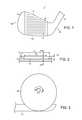
- FIG. 1shows a golf club head of the present invention
- FIG. 2shows a cross-sectional view of a club head of the present invention along a groove
- FIG. 3shows a preferred groove cutting setup
- FIG. 4shows a comparison of a groove of the golf club head of FIG. 1 as viewed along lines 4 - 4 of FIG. 2 with a known groove;
- FIG. 5shows a comparison of a groove of the golf club of FIG. 1 and a known groove
- FIGS. 6-9each show a cross-section of a preferred groove of the present invention.
- FIG. 10shows a cross-section of a preferred groove of the present invention
- FIG. 11shows a stepped face-groove junction of the present invention
- FIGS. 12-14each show a cross-section of a preferred groove of the present invention.
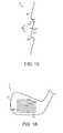
- FIG. 15shows a partial cross-sectional view of a golf club head striking face of the present invention
- FIGS. 16-22show front views of golf club heads of the present invention.
- FIGS. 23-31each show a cross-section of a portion of a golf club head striking face of the present invention.
- FIG. 1shows a golf club head 1 of the present invention.
- the golf club head 1includes a body 10 defining a front surface 11 , a sole 13 , a top line 14 , a heel 15 , a toe 16 , and a hosel 17 .
- the striking face of the front surface 11which contains grooves 12 therein, and the sole 13 may be unitary with the body 10 , or they may be separate bodies, such as inserts, coupled thereto.
- the club head 1is illustrated as an iron-type golf club head, the present invention may also pertain to a utility-type golf club head or a wood-type club head.
- FIG. 2shows a cross-sectional view of the club head 1 along a groove 12 .
- Grooves 12are machined into the surface of the striking face 11 , which allows the draft angle to be decreased.
- Grooves 12extend from a toe end of the club head 1 to a heel end of the club head 1 .
- the grooves 12are shallow at both the toe and heel portions of the club head 1 , and are deep in the central regions.
- Grooves 12have a first distance d 1 measured along the surface of striking face 11 and a second distance d 2 measured along the deepest portion of the grooves, which have a depth d 3 .
- first distance d 1is an overall distance
- second distance d 2is a maximum depth distance.
- the groove depth along the maximum depth distance d 2is substantially constant.
- the maximum depth distance d 2is at least 0.25 inch shorter than the overall distance d 1 .
- the groove draft angle ⁇ranges from about 0.5° to 12°, more preferably about from 4° to 6°, and most preferably 5°.
- Grooves 12are radiused at the toe and heel portions of the club head 1 , and are about 0.02 inch deep at a geometric center of the face 11 . Grooves 12 are machined into the strike face surface 11 .
- the club head 1is retained in a mold, which preferably is formed of a material soft enough to not damage the club head 1 yet resilient enough to firmly retain the golf club head 1 , and a cutter, preferably a round cutter or a saw cutter, is used to form the grooves 12 .
- the toe and heel portionsare radiused about an axis of rotation that is perpendicular to a longitudinal axis of the groove. Furthermore, that axis of rotation is approximately parallel to face 11 of club head 1 .
- Preferred cuttershave a diameter from 3 ⁇ 8 inch to 3 ⁇ 4 inch.
- a preferred range of groove radiiinclude from 0.125 inch to 5 inches, with 0.25 inch to 2.5 inches being more preferred. Having radiused grooves 12 facilitates removal of dirt, grass, sand, and other materials that typically become embedded within the grooves of a golf club during normal use by eliminating corners that can trap these materials.
- FIG. 3shows a preferred groove cutting setup illustrating cutter 20 with groove 12 .
- FIG. 4shows a comparison of a groove 12 of the present invention with a typical groove 22 of known golf club heads.
- the groove 12preferably has a depth of 0.02 inch, which is the USGA limit. Due to loose tolerances, known grooves 22 were designed well short of this limit. Similarly, known manufacturing processes required a large draft angle ⁇ , typically around 16°. The draft angle ⁇ of grooves 12 is much smaller, increasing the cross-sectional area of the groove and groove volume for a given length.
- the governing bodies of golfplace limitations of the geometry of grooves 12 .
- the increased tolerance control afforded by machining the grooves 12 of the present inventionallows the actual groove geometry to be closer to the limits than was previously achievable.
- the grooves 12 of the present inventionmaximize groove volume, enhancing the groove performance during use.
- the groovesbetter grip the ball, allowing a golfer to apply more spin to the ball.
- the golfer's control over the ball, both during ball flight and subsequent to flight, such as when landing and settling on a golf green,are increased.
- the grooves 12 of the present inventionalso result in a golf club head that is more aesthetically pleasing and that allows better ball control.
- FIG. 5shows a comparison of a groove 12 of the present invention with a typical groove 22 of known golf club heads.
- the known grooves 22are quite rounded.
- the grooves 12 of the present inventionare much sharper. The edges are more defined, the depth is greater, and the dimensions are more consistent and closer to the limits. All of these factors allow the golf club head 1 to better grip the golf ball, increasing the user's control over the ball.
- the face 11 of the club head 1 of the present inventionis also enhanced to provide additional ball control and enhanced performance.
- the strike surface 11is provided with a roughened texture.
- a common measure of roughness in surface finishis average roughness, Ra.
- Raalso known as Arithmetic Average (AA) and Center Line Average (CLA), is a measure of the distance from the peaks and valleys to the center line or mean. It is calculated as the integral of the absolute value of the roughness profile height over the evaluation length:
- Ra1 L ⁇ ⁇ 0 L ⁇ ⁇ r ⁇ ( x ) ⁇ ⁇ d x
- the face 11is roughened by machining, preferably with a Computer Numerically Controlled (CNC) mill.
- CNCComputer Numerically Controlled
- Known golf clubshave a face roughness at most 40 Ra. At least a portion of the face 11 in the proximity of the grooves, and more preferably the entire face 11 , is machined such that it has a substantially uniform textured surface with a roughness greater than 40 Ra.
- the roughnessis from 75 Ra to 300 Ra, more preferably from 100 Ra to 200 Ra, and most preferably from 120 Ra to 180 Ra.
- Providing a textured strike faceallows the golfer to apply more friction to the ball during use, allowing the golfer to put more spin on the ball and have greater control of the ball.
- golfershave to take a full swing to induce enough golf ball spin to control the ball movement on a golf green.
- a golfercan induce golf ball spin in “partial” shots, or shots when the golfer is not taking a full swing.
- the textured strike surface of the present inventionalso distributes the shear force resulting from the golf swing over a greater area of the golf ball. This reduces cover damage and extends golf ball life.
- the faceis selectively textured to enhance playability.
- the face point of contact with the ballvaries depending upon the particular golf shot being performed. If the ball is lying on the fairway and the golfer takes a “regular” swing, then the golfer strives to make contact with the ball on the lower portion of the club face, typically the lower, central portion of the club face. For a chip shot, the golfer may likely alter the club face angle, striking the ball higher on the club face. Of course, this would change the angular orientation of the club head relative to the golf ball at impact. For a flop shot, the golfer opens the club face to a large degree, further changing the face contact point and angular orientation.
- Still other portions of the facemay be used for other types of shots; for example, some golfers use the extreme outer toe portion of the face, with the toe pointed toward the playing surface, as the ball contact point for chip shots.
- the facemay therefore be selectively textured to enhance each of the different types of shots the golfer may perform.
- FIGS. 15 and 23 - 31each show a partial cross-sectional view of a golf club head striking face of the present invention including surface texture that may be created by milling, laser etching and/or chemical etching.
- FIG. 15shows a close-up view of the texture left by a milling process in which the face 11 has been textured, such as by milling with a single direction of cutting. The result is a directionally textured face 11 .
- the face surface 11contains a plurality of notches 50 forming a plurality of ridges defined by a first, relatively long surface 51 and a second, relatively short surface 52 .
- the top-to-bottom direction of travel in FIG. 15is the “smooth” direction of travel, in that the notches 50 will not impede travel.
- the bottom-to-top direction of travelis the “notched” direction of travel, in that travel will be stopped at each notch wall junction.
- Another way of describing these surfaces 51 , 52is that the first surface 51 is a departing surface in that, in the smooth direction of travel, this surface departs away from a nominal vertical plane of the striking face surface 11 .
- the second surface 52can be described as a return or returning surface in that, in the smooth direction of travel, this surface returns to the nominal vertical plane, or nominal striking face plane.
- the second surface 52is notched outward relative the golf ball, so it may impart some spin thereto during use of the resulting golf club.
- the notch surfaces 51 , 52define an exterior angle ⁇ 1 therebetween, that may be an obtuse, acute or right angle, but is preferably acute.
- the first notch surfaces 51extend outward relative a vertical plane at an internal angle ⁇ 2 .
- the external angle ⁇ 1is greater than the internal angle ⁇ 2 , and more preferably the external angle ⁇ 1 is greater than twice the internal angle ⁇ 2 .
- FIG. 15shows only a portion of the strike face 11 , and does not illustrate any grooves 12 .
- the club headpreferably also includes grooves, with the face being textured in between the grooves and/or in non-grooved areas of the face 11 .
- FIG. 16shows a front view of a club head 1 of the present invention.
- the central portion of the club head 1 intermediate the heel and toecontains grooves 12 .
- the face 11is textured with notches 50 among the grooves 12 in the central portion of the club head. These notches are shown simply as dashed lines for the sake of clarity in the illustrated embodiments.
- the textured surfaceis not limited to the areas actually covered by the dashed lines.
- the face texturemay also include a plurality of spaced ridges located between adjacent grooves that, in some embodiments, also provide a “smooth” direction of travel and a “notched” direction of travel.
- ridges 60are spaced by generally planar portions 63 of strike face 11 .
- planar portions 63are also planar relative to each other and are oriented so that they are generally parallel to the intended loft plane of the golf club. As a result, planar portions 63 generally are located within a nominal striking face plane.
- Each of ridges 60includes a first surface 61 and a second surface 62 .
- First surface 61is angled relative to planar portions 63 by an angle ⁇ 4 and preferably oriented so that it extends further away from planar portions in a direction from a top line toward a leading edge of the golf club.
- Second surface 62extends between the end of first surface 61 furthest from planar portion 63 and an end of planar portion 63 so that the ridges 60 generally form a saw-tooth pattern.
- Second surface 62is angled relative to first surface 61 by an angle ⁇ 3 that, in the embodiment of FIG. 23 , is complimentary to angle ⁇ 4 so that second surface 62 is approximately orthogonal to planar portion 63 .
- FIG. 1shows a first surface 61 that, shown in FIG.
- second surface 62is angled relative to first surface 61 so that second surface 62 forms an acute external angle ⁇ 5 relative to planar portion 63 . It should be appreciated that angles ⁇ 3 and ⁇ 5 may be acute, obtuse or right angles.
- first surface 61 and second surface 62have approximately the same length so that, the ridges have an approximately equilateral triangular cross-section.
- angles ⁇ 4 and ⁇ 5are approximately supplementary angles and angle ⁇ 3 may be an acute, right or obtuse angle.
- the pitch of ridges 60varies across surface 11 .
- ridges 60are closer together in a portion of surface 11 , such as a portion adjacent groove 12 that is on the leading edge side of a portion of front surface 11 .
- the pitchmay be altered by changing the length of portions 63 .
- the density of ridges 60 immediately adjacent groove 12is greater on one side of groove 12 than on the other.
- surface 11includes ridges having a progressive configuration between adjacent grooves 12 .
- a plurality of ridges 70is provided between adjacent grooves 12 having first and second surfaces 71 , 72 that vary in length and angle across the portion of surface 11 .
- a first ridge 70includes a first surface 71 and a second surface 72 that have approximately equal lengths so that first ridge 70 has a generally equilateral triangular shaped cross-section.
- the first surface 71increases in length progressively from the first ridge, while second surface 72 decreases in length and the resulting apex angle ⁇ 6 decreases across surface 11 .
- the ridgesprogress so that apex angle ⁇ 6 reduces in the direction from the top line toward the leading edge of the golf club.
- first surface 81is held constant while the length and orientation of second surface 82 is altered progressively across surface 11 .
- angle ⁇ 7 of second surface 82 relative to surface 11changes progressively between an obtuse and an acute angle and the length of second surface 82 varies accordingly to meet first surface 81 .
- the golf clubincludes a plurality of ridges 90 that have a generally rectangular cross-sectional shape, as shown in FIG. 29 .
- Each of ridges 90generally includes generally orthogonal surfaces 91 and a parallel surface 92 that extends between surfaces 91 to form the generally rectangular ridge 90 .
- ridges 90are spaced by a distance “y” that is between approximately 0.005 and 0.030 inch.
- a golf clubmay be provided with a combination of ridges, such as rectangular and triangular.
- ridgessuch as rectangular and triangular.
- a combination of rectangular ridges 90 and triangular ridges 100is provided between a pair of adjacent grooves 12 .
- the ridgesmay have any configuration, such as those described above.
- portions of surface 11may include ridges having similar configuration, such as a first portion having rectangular ridges 90 and a second portion having triangular ridges 100 .
- the height “x” of the ridgesis less than or equal to 0.001 inch and the roughness is from 75 Ra to 300 Ra, more preferably from 100 Ra to 200 Ra, and most preferably from 120 to 180 Ra.
- the width of the ridges “z”is preferably between 0.005 inch and 0.030 inch.
- the cross-sectional area of each of the ridgesis preferably between 0.000005 inch 2 and 0.00003 inch 2 .
- FIG. 17shows a front view of another club head 1 of the present invention.
- the grooves 12are positioned as with the other embodiments of the invention.
- the texturing 50 in this embodimentis angled relative the grooves.
- the texturing 50is illustrated with dashed lines with the notches 50 directed perpendicularly relative to the illustration lines.
- the notches 50are directed in an upper toe to lower heel direction.
- the angle ⁇ n between the grooves 12 and the notches 50preferably is approximately 5°-30°. It will be noted that the angle reference above the club head 1 illustrated in FIG. 17 is made between an extension of the uppermost notch reference and a horizontal line, parallel to the grooves 12 .
- the linear arrangement of notchesis angled from approximately 5°-30° relative to the grooves 12 . It follows that a vertical projection of the departing surface 51 makes the same angle ⁇ with a nominal line perpendicular to the grooves 12 .
- the angled texturing 50allows the notches 50 to be square to the line of the shot when the club head 1 is opened, such as for a chip shot. This allows the golfer to apply pure backspin (as opposed to including some degree of side spin) to the ball during the swing, even with an opened club head.
- FIG. 18shows a front view of another club head 1 of the present invention.
- the grooves 12are positioned as with the other embodiments of the invention.
- the texturing in this illustrated embodimentis arced or curved.
- the arcingis centered about at point P that is located at a central portion of the leading edge of the club head 1 , preferably in line with the geometric center of the club head 1 and/or its center of gravity.
- the notches 50are directed toward point P. While the texturing is only shown in a lower, central region of the face 11 , more or less of the face 11 could be textured. For example, the entire face 11 may be textured.
- the texturing 50is shown in the illustrated embodiment of FIG.
- Arced texturing 50allows the golfer to strike the ball with transverse texturing (that is, with the notches 50 directed in-line with the intended line of ball flight) in numerous club head orientations. However, as the amount of transverse texturing for a particular club head orientation is less with arced texturing 50 than with specifically angled linear texturing (see, for example, FIG. 17 ), it is contemplated that this set up may be better suited for golfers of high skill level.
- FIG. 19shows a front view of another club head 1 of the present invention.
- the grooves 12are again positioned as with the other embodiments of the invention.
- the texturing 50 in this illustrated embodimentis a combination of arced notches 50 a (see FIG. 18 ) and angled notches 50 b (see FIG. 17 ).
- the club head 1thus includes two types of texturing 50 a , 50 b .
- This texturing combinationprovides the benefits of both of these previously described embodiments. It is possible that there may be some overlap of the different textures 50 a , 50 b , perhaps intentionally. A standard milling cutter may be used.
- these areasmay be machined with a staggered mill cutter. That is, the milling blades may contain spaces such that some portions of the face are not cut in a single pass of the mill.
- the overlapped texturingmay be specifically programmed into the CNC milling machine.
- FIG. 20shows a front view of another club head 1 of the present invention, with the grooves 12 positioned as with the other embodiments of the invention.
- the texturing 50 in this illustrated embodimentis a combination of the “straight” texturing 50 a (see FIG. 16 ) and angled texturing 50 b (see FIG. 17 ).
- the face 11contains two distinct sets of directional texturing 50 a , 50 b .
- the texturing 50 a in the lower and central portions of the face 11are straight, while the texturing 50 b in the upper and toe portions of the face 11 are angled.
- This designprovides the golfer with the benefits of having transverse texturing in both square and open club head orientations.
- the angle between the axes of the sets of directional texturing 50 a , 50 bpreferably is approximately 5°-25°, with 10° ⁇ 5° and 20° ⁇ 5° being more preferred.
- FIG. 21shows a front view of another club head 1 of the present invention, with two sets of angled notched texturing.
- a first set of directional texturing 50 ais angled at a first angle ⁇ 1 relative the grooves 12
- a second set directional texturing 50 bis angled at a second angle ⁇ 2 relative the grooves 12 , with the second angle ⁇ 2 being greater than the first angle ⁇ 1 .
- the first angle ⁇ 1is made between an extension of a reference line of the first set of directional texturing 50 a and a horizontal reference parallel to the grooves 12
- the second angle ⁇ 2is made between an extension of a reference line of the second set of directional texturing 50 b and the horizontal reference.
- the first portion of texturing 50 ais positioned on lower and central regions of the face 11 , allowing the golfer to strike the ball with transverse notches 50 a with a slightly open club head.
- the second portion of texturing 50 bis positioned on central and upper regions of the face 11 , allowing the golfer to strike the ball with transverse notches 50 b with a larger degree of club head openness.
- the greater-angled texturing 50 bis positioned higher on the face than the less-angled texturing 50 a .
- Preferred exemplary ranges for the anglesare 5° ⁇ 1 ⁇ 15° and 15° ⁇ 2 ⁇ 25°.
- FIG. 22shows a front view of another club head 1 of the present invention, with three sets of notched texturing.
- the first set 50 ais arced texturing (see FIG. 18 ) and the second set 50 b is angled linear texturing (see FIGS. 17 , 20 , and 21 ) have both been described above.
- the face 11further includes a third set of texturing 50 c .
- These notchesare again angled perpendicularly to the dashed reference lines.
- the reference linesare substantially perpendicular to the grooves 12 , with the notches directed toward the toe 16 . This allows the golfer to use the extreme toe portion of the face for a certain style of chipping with the toe pointed toward the playing surface.
- This inventive directional texture schemeallows the golfer to strike the ball with transverse notches in a great variety of club head orientations.
- Golf club facesare often plated to protect the club head material from environmental factors that may adversely affect the club head, such as by causing it to rust. However, such plating may smooth the surface, effectively canceling the benefit of the textured face of the instant invention.
- At least a portion of the instant club head facepreferably is left raw and not plated. This helps ensure that the benefits of the textured face are realized.
- Preferably a quarter of the faceis raw, and more preferably at least a third of the face is raw. In one preferred embodiment, the entire face is left in a raw condition.
- the texturing 50has been shown in the drawings as dashed lines so that it can be readily distinguished from the grooves 12 .
- This use of dashed linesis solely for the sake of clarity in the illustrated embodiments. This should not be interpreted as an indication that the texturing is hidden.
- the texturingis provided on the face 11 of the club head 1 , and is visible in the finished product.
- the textured surfaceis not limited to the areas actually covered by the dashed lines. Rather, only a few lines are shown to indicate the texturing so that the figures do not become too crowded and unreadable.
- the entire portion of the face 11 in and among the notch reference lines 50is textured. This portion may include the entire striking face 11 , or only a portion of the face 11 .
- the inventive golf clubsconform with all USGA regulations.
- the golf club head 1preferably is formed of a soft base metal, such as a soft carbon steel, 8620 carbon steel being an example.
- a chrome finishmay be applied to the base metal to inhibit wear and corrosion of the base metal. If included, the chrome finish preferably includes a non-glare layer.
- the chrome finish layerpreferably has a thickness between 0.005 ⁇ in and 280 ⁇ in, with 80 ⁇ in a preferred thickness.
- a nickel finishmay additionally be applied to the base metal as a sub-layer for chrome or another finish layer or may alternatively be applied to the base metal as the finish layer. If included, the nickel finish preferably has a thickness between 400 ⁇ in and 1200 ⁇ in, with 800 ⁇ in a preferred thickness.
- the grooves 12 and strike face 11 of the present inventionenhance performance, especially in adverse conditions.
- the higher friction possible with the golf club head 1allows a tighter grip on the golf ball during “wet” or “grassy” conditions than was previously possible.
- the club head of the present inventionwas tested, and as shown in Table 1 below, the generated revolutions per minute of a struck golf ball were substantially the same as those generated with a conventional club for a full dry shot, but were increased in a half dry shot and in both a full wet shot and a half wet shot.
- the “dry” shotscontained substantially no moisture on the club face and ball.
- Table 1shows the revolutions per minute of a golf ball after being struck with a standard club or a spin milled club of the present invention, and illustrates the benefit of the spin milled grooves over standard grooves.
- a preferred method of making the club head 1includes first making a club head body. This may be done by casting, forging, or any other manufacturing method. The face is then machined such that it is substantially smooth and flat, preferably flat within ⁇ 0.002 inch. This preferably may be done by fly-cutting the face, which is cutting with a single-point tool fixed to the end of an arm protruding from a vertical milling shaft. Having a flat face allows the golfer to achieve consistent results during use.
- the bodypreferably is nested during the face flattening process. That is, the body is retained within a housing such that it is substantially immobile. The face is left exposed so that it can be worked on.
- the housingmay be padded or otherwise designed such that it does not damage the club head.
- the groovesare created and the surface is roughened as described above. While it is preferred that the grooves be spin milled prior to roughening the surface, the order of these steps is not essential. In fact, it is possible that they be performed substantially simultaneously, or with at least some amount of overlap.
- the spin milled groovesmay have very sharp edges, which could have an adverse effect on a golf ball during use.
- the groovesmay be deburred to remove any sharp edges in the groove-to-face junction. This creates a radius at the junction, the radius preferably being less than 0.01 inch.
- This deburringcan be carried out in a variety of ways.
- the junctionmay be filed, such as with a wire brush or a file, such as a carbide file.
- the junctioncan be deburred by blasting. This may include impacting small beads at the junction at high speeds.
- the facemay be masked.
- Maskingincludes placing a physical barrier on the face adjacent the grooves such that the projected particles cannot impact the face.
- a nozzlecan be used to accurately direct the projected material only at the junction.
- FIGS. 6-9each show a cross-section of a preferred groove 12 that may be formed by the method described above.
- the groove 12includes a first portion 121 adjacent to and interacting with the club face 11 .
- the edges of the groove 12have been deburred, either having a radius or being angled.
- An angled edgeis preferred for the spin milling process described above, and a preferred range of angles A 1 is about 10° to 50°.
- the width W 1 of the groove 12 at the strike face 11which is the widest portion of the groove 12 , is about 0.035 inch. This corresponds to the maximum width allowable by the USGA.
- the first portion 121is shallow, preferably having a depth D 1 of less than 0.005 inch, with 0.001 to 0.003 inch being more preferred.
- the first portions of the illustrated embodiments of FIGS. 6-9are similar, but extending to varying depths D 1 .
- the embodiment illustrated in FIG. 6has the shallowest depth D 1
- the embodiment illustrated in FIG. 7has the deepest depth D 1 .
- the groove 12includes a second portion 122 adjacent to the first portion 121 .
- This portion 122preferably has substantially parallel walls that are substantially perpendicular to the face 11 , “substantially” herein meaning the walls may be angled at an angle A 2 of up to about 20°.
- the walls defining the second portion 122are spaced as far apart as possible to maximize the volume of the groove 12 .
- a preferred range of widths W 2 , W 3is about 0.033 to 0.027 inch.
- the maximum width W 2 of the second portion 122preferably may be from about 80% to 98% of the maximum groove width W 1 .
- the width W 3 at a bottom portion of the second portion 122is at least about 80% of the width W 2 at a top portion of the second portion 122 .
- a preferred range of depths D 2is between about 0.005 and 0.008 inch.
- the second section depth D 2is at least half the overall groove depth D.
- the overall groove depth Dpreferably is between about 0.0175 and 0.0225 inch, more preferably about 0.02 inch.
- the groove 12includes a third portion 123 adjacent to the second portion 122 .
- This portion 123has a V-shape, having an angle A 3 of about 90°.
- the width of the third portion 123decreases from the top portion thereof (nearest the face 11 ) to the bottom portion thereof.
- the width at the bottom of the third portionis less than about half of the width of the top portion.
- the depth D 3 of this third section 123may be from about 0.012 to 0.015 inch.
- the depth D 3 of this third section 123preferably is at least twice the depth D 2 of the second portion 122 .
- the third portion 123has a depth D 3 that is about 60% to 75% of the overall groove depth D.
- the groove 12includes a fourth portion 124 adjacent to the third portion 123 .
- This portion 124is radiused to join the walls of the third section 123 .
- a preferred radius R 4is less than 0.012 inch.
- Pitch ratio Pis calculated according to the following formula:
- Ais the cross-sectional area of the groove
- Wis the groove width (measured at the face surface)
- Sis the spacing between adjacent grooves.
- the pitch ratio Pthus has the units of length 2 /length.
- the governing bodies of the Rules of Golfhave proposed new rules limiting the pitch ratio P to be less than 0.0025 in. 2 /in.
- FIG. 10shows a cross-section of a preferred groove 12 that may be formed by the spin mill method described above.
- the line of the face 11has been extended across the groove 12 for illustrative purposes.
- This groove 12may be referred to as a “V-groove,” as the side walls converge from points adjacent the face 11 toward their union at the bottom of the groove 12 .
- This unionmay be radiused as discussed above.
- the face-groove junctionsare deburred to avoid sharp edges that may cut or otherwise damage a golf ball.
- the groove edgesmay be radiused or angled. Exemplary angles include the range of 0.005 in. to 0.02 in.
- the face-groove junctionsmay also contain a series of steps, each of which may or may not be radiused.
- a stepped face-groove junctionis illustrated in FIG. 11 . While three steps are shown in this exemplary embodiment, more or fewer steps could be included.
- a preferred number of stepsinclude the range of 1 to 10 steps.
- the use of a stepped face-groove junctionmay increase the golfer's ability to impart spin to the ball, enhancing the golfer's ability to control the ball flight and landing/settling characteristics.
- a preferred range for the length of the rise (the “vertical” part of the step) and run (the “horizontal” part of the step) of each stepincludes the range of 0.0015 in. to 0.01 in.
- the rise(s) and run(s)be of the same dimension, but they may also be constructed such that the rise is greater than the run or vice versa. Additionally, it is possible that individual rises of a plurality of rises may be of the same or differing values. The runs may also be of similar of dissimilar values. This stepped face-groove junction can be used with any of the grooves described herein.
- the maximum allowable groove width W allowed by the Rules of Golfis 0.035 in., and the space S between edges of adjacent grooves must be no less than three times the groove width W and not less than 0.075 in. Additionally, the maximum groove depth D allowed by the Rules of Golf is 0.02 in. Setting the width W to 0.035 in. and the spacing 5 to 0.105, the only variable in the pitch ratio calculation is the cross-sectional area A.
- the area Ais a function of the groove depth, groove width, and wall angles.
- the grooves 12may be characterized by the inclusive angle ⁇ formed by the two side walls.
- the inclusive angle ⁇is equivalent to twice the draft angle ⁇ .
- Preferred values for the inclusive angle ⁇include the range of 85° to 95°, with 90° ⁇ 3° being more preferred.
- the depth D of these groovesmay be less than 0.02 in.
- the depth Dis within the range of 0.015 in. to 0.02 in., 0.015 in. to 0.018 in. being more preferred.
- the pitch ratio Pis approximately 0.0025 in. 2 /in or less.
- FIG. 12shows a cross-section of another preferred groove of the present invention.
- This illustrated grooveis similar to a V-groove, but has a bottom wall such that the side walls do not intersect.
- These grooves 12may be characterized by their draft angle ⁇ , which preferably may be within the range of 30° to 40°, 35° ⁇ 3° being more preferred. Setting the depth D and width W to the maximum allowable dimensions yields an area A of 0.00037 in. 2 to 0.00047 in. 2 , more preferably approximately 0.0004 in 2 .
- the width W B of the bottom wallmay also be used to characterize the groove 12 .
- the bottom wall width W Bis 1 ⁇ 3 to 1 ⁇ 6 the groove width W, with 1 ⁇ 4 to 1 ⁇ 5 being more preferred.
- the pitch ratio Pis approximately 0.0025 in. 2 /in or less.
- the junctions between the side and bottom wallsmay be radiused, in which case the bottom wall width W B may be measured between intersections of bottom and side wall extensions. That is, the bottom wall width W B may be measured as if the junctions were not radiused.
- Decreasing the draft angle ⁇ of the groove 12 illustrated in FIG. 12modifies its shape such that it may be categorized as a “U-groove.”
- Preferred values for the draft angle ⁇include 12° to 20°, with 16° ⁇ 2° being more preferred.
- the depth Dpreferably is less than the maximum allowable, and within the range of 0.018 in. to 0.02 in.
- the width Wmay be slightly less than the maximum allowable dimension, for example within the range of 0.03 in. to 0.035 in. This yields an area A of approximately 0.0004 in. 2 to 0.0005 in. 2
- the pitch ratio Pis approximately 0.0025 in. 2 /in. or less.
- any steps that may be used to form the face-groove junctionmay be ignored. Of course, such steps may be taken into account when making the calculations.
- One way to enhance the functionality of the grooves 12 of a golf club headis to increase the volume of the individual grooves.
- One such preferred groove designis shown in FIG. 13 .
- the spacing Sis not held to the minimum value and is instead increased, thus allowing an increased area A and still yielding pitch ratio P values within the preferred range.
- the inclusive angle ⁇ formed by the side wallspreferably is within the range of 50° to 55°, with 52° ⁇ 1° being more preferred.
- the groove width Wpreferably is maximized to 0.035 in., but 0.032 in. ⁇ 0.002 in. is also preferred.
- the depth Dpreferably is maximized to 0.02 in., 0.017 in. ⁇ 0.002 in. is also preferred.
- FIG. 14illustrates another groove 12 of increased volume.
- the spacing Sis increased above the minimum allowed value.
- the inclusive angle ⁇ formed by the side wallspreferably is within the range of 2° to 10°, with 4° ⁇ 1° being more preferred.
- the groove width Wpreferably is maximized to 0.035 in., but 0.032 in. ⁇ 0.002 in. is also preferred.
- the depth Dpreferably is maximized to 0.02 in., 0.017 in. ⁇ 0.002 in. is also preferred. This yields a groove area A that is within the range of 0.00039 in. 2 to 0.00043 in.
- the bottom wall width W Bmay be 80% to 95% of the groove maximum width W measured at the strike face 11 .
- directional referencessuch as rear, front, lower, bottom, upper, top, etc. are made with respect to the club head when grounded at the address position. See, for example, FIG. 1 .
- the direction referencesare included to facilitate comprehension of the inventive concepts disclosed herein, and should not be read or interpreted as limiting.
Landscapes
- Health & Medical Sciences (AREA)
- General Health & Medical Sciences (AREA)
- Physical Education & Sports Medicine (AREA)
- Golf Clubs (AREA)
Abstract
Description
| TABLE 1 | ||
| Shot Conditions | Standard | Spin Milled |
| Dry-full | 12250 | 12000 |
| Dry-half | 6500 | 7750 |
| Wet-full | 8000 | 12000 |
| Wet-half | 4000 | 8000 |
Claims (15)
Priority Applications (2)
| Application Number | Priority Date | Filing Date | Title |
|---|---|---|---|
| US13/412,369US8517861B2 (en) | 2003-12-12 | 2012-03-05 | Golf club head having a grooved and textured face |
| US13/975,043US9403068B2 (en) | 2003-12-12 | 2013-08-23 | Golf club head having a grooved and textured face |
Applications Claiming Priority (8)
| Application Number | Priority Date | Filing Date | Title |
|---|---|---|---|
| US52870803P | 2003-12-12 | 2003-12-12 | |
| US10/902,064US7273422B2 (en) | 2003-12-12 | 2004-07-30 | Spin milled grooves for a golf club |
| US11/711,096US7568983B2 (en) | 2004-07-30 | 2007-02-27 | Golf club head groove configuration |
| US12/007,223US7862450B2 (en) | 2003-12-12 | 2008-01-08 | Golf club head groove configuration |
| US12/107,280US7758449B2 (en) | 2003-12-12 | 2008-04-22 | Golf club head having a grooved and textured face |
| US12/339,378US7976404B2 (en) | 2003-12-12 | 2008-12-19 | Golf club head having a grooved and textured face |
| US13/180,488US8128511B2 (en) | 2003-12-12 | 2011-07-11 | Golf club head having a grooved and textured face |
| US13/412,369US8517861B2 (en) | 2003-12-12 | 2012-03-05 | Golf club head having a grooved and textured face |
Related Parent Applications (1)
| Application Number | Title | Priority Date | Filing Date |
|---|---|---|---|
| US13/180,488ContinuationUS8128511B2 (en) | 2003-12-12 | 2011-07-11 | Golf club head having a grooved and textured face |
Related Child Applications (1)
| Application Number | Title | Priority Date | Filing Date |
|---|---|---|---|
| US13/975,043ContinuationUS9403068B2 (en) | 2003-12-12 | 2013-08-23 | Golf club head having a grooved and textured face |
Publications (2)
| Publication Number | Publication Date |
|---|---|
| US20120165114A1 US20120165114A1 (en) | 2012-06-28 |
| US8517861B2true US8517861B2 (en) | 2013-08-27 |
Family
ID=41431820
Family Applications (4)
| Application Number | Title | Priority Date | Filing Date |
|---|---|---|---|
| US12/339,378Expired - LifetimeUS7976404B2 (en) | 2003-12-12 | 2008-12-19 | Golf club head having a grooved and textured face |
| US13/180,488Expired - LifetimeUS8128511B2 (en) | 2003-12-12 | 2011-07-11 | Golf club head having a grooved and textured face |
| US13/412,369Expired - Fee RelatedUS8517861B2 (en) | 2003-12-12 | 2012-03-05 | Golf club head having a grooved and textured face |
| US13/975,043Expired - LifetimeUS9403068B2 (en) | 2003-12-12 | 2013-08-23 | Golf club head having a grooved and textured face |
Family Applications Before (2)
| Application Number | Title | Priority Date | Filing Date |
|---|---|---|---|
| US12/339,378Expired - LifetimeUS7976404B2 (en) | 2003-12-12 | 2008-12-19 | Golf club head having a grooved and textured face |
| US13/180,488Expired - LifetimeUS8128511B2 (en) | 2003-12-12 | 2011-07-11 | Golf club head having a grooved and textured face |
Family Applications After (1)
| Application Number | Title | Priority Date | Filing Date |
|---|---|---|---|
| US13/975,043Expired - LifetimeUS9403068B2 (en) | 2003-12-12 | 2013-08-23 | Golf club head having a grooved and textured face |
Country Status (1)
| Country | Link |
|---|---|
| US (4) | US7976404B2 (en) |
Cited By (9)
| Publication number | Priority date | Publication date | Assignee | Title |
|---|---|---|---|---|
| US20130281226A1 (en)* | 2012-04-24 | 2013-10-24 | Bridgestone Sports Co., Ltd. | Forming method and golf club head |
| US20130344984A1 (en)* | 2003-12-12 | 2013-12-26 | Acushnet Company | Golf club head having a grooved and textured face |
| US20170151473A1 (en)* | 2006-08-22 | 2017-06-01 | Max Out Golf, Llc | Treatment for the hitting surface of a golf club and a method for applying the same |
| US10343034B2 (en) | 2016-12-19 | 2019-07-09 | Karsten Manufacturing Corporation | Localized milled golf club face |
| US10857430B2 (en) | 2016-12-19 | 2020-12-08 | Karsten Manufacturing Corporation | Localized milled golf club face |
| US10874915B2 (en) | 2017-08-10 | 2020-12-29 | Taylor Made Golf Company, Inc. | Golf club heads |
| US11161020B2 (en) | 2016-12-19 | 2021-11-02 | Karsten Manufacturing Corporation | Localized milled golf club face |
| US11285365B1 (en)* | 2018-11-15 | 2022-03-29 | Cobra Golf Incorporated | Golf club with perimeter face machining |
| US11701557B2 (en) | 2017-08-10 | 2023-07-18 | Taylor Made Golf Company, Inc. | Golf club heads |
Families Citing this family (45)
| Publication number | Priority date | Publication date | Assignee | Title |
|---|---|---|---|---|
| US7918747B2 (en)* | 2004-07-30 | 2011-04-05 | New Text | Golf club head having a grooved face |
| US8752271B2 (en) | 2004-07-30 | 2014-06-17 | Acushnet Company | Golf club groove configuration |
| US7758449B2 (en)* | 2003-12-12 | 2010-07-20 | Acushnet Company | Golf club head having a grooved and textured face |
| US10046484B2 (en)* | 2007-12-19 | 2018-08-14 | Taylor Made Golf Company, Inc. | Mold and associated methods |
| US20110275451A1 (en)* | 2007-12-19 | 2011-11-10 | Taylor Made Golf Company, Inc. | Textured golf club face |
| US8628434B2 (en) | 2007-12-19 | 2014-01-14 | Taylor Made Golf Company, Inc. | Golf club face with cover having roughness pattern |
| US9174099B2 (en) | 2007-12-19 | 2015-11-03 | Taylor Made Golf Company, Inc. | Golf club face |
| JP5161692B2 (en)* | 2008-08-01 | 2013-03-13 | ダンロップスポーツ株式会社 | Iron type golf club set |
| US8147352B2 (en) | 2009-04-10 | 2012-04-03 | Nike, Inc. | Golf club having hydrophobic and hydrophilic portions |
| US8083612B2 (en) | 2009-08-06 | 2011-12-27 | Nike, Inc. | Golf club head or other ball striking device having one or more face channels |
| JP5485780B2 (en)* | 2010-04-30 | 2014-05-07 | ブリヂストンスポーツ株式会社 | Golf club head |
| JP5485779B2 (en)* | 2010-04-30 | 2014-05-07 | ブリヂストンスポーツ株式会社 | Golf club head |
| US20120071269A1 (en)* | 2010-08-20 | 2012-03-22 | Nike, Inc. | Golf Clubs With Golf Club Heads Having Grooves Formed With Textured Surfaces |
| US8827832B2 (en) | 2011-04-12 | 2014-09-09 | Cobra Golf Incorporated | Golf club heads with enlarged grooves |
| US8535172B2 (en) | 2011-07-28 | 2013-09-17 | Cobra Golf Incorporated | Golf club with universal hosel and/or spacer |
| US8684861B2 (en) | 2011-08-23 | 2014-04-01 | Sri Sports Limited | Golf club head |
| US8979679B2 (en) | 2011-12-27 | 2015-03-17 | Nike, Inc. | Golf ball having hydrophilic and hydrophobic portions |
| JP5977065B2 (en)* | 2012-04-10 | 2016-08-24 | ブリヂストンスポーツ株式会社 | Golf club head |
| US8979670B2 (en) | 2013-01-18 | 2015-03-17 | Dunlop Sports Company, Ltd. | Golf club head with textured striking face |
| US9737771B2 (en) | 2013-07-18 | 2017-08-22 | Karsten Manufacturing Corporation | Golf club heads having a hydrophobic surface and methods to manufacture golf club heads having a hydrophobic surface |
| TW201509488A (en)* | 2013-09-06 | 2015-03-16 | Advanced Int Multitech Co Ltd | Ball-hitting face of golf club head |
| US9393464B2 (en)* | 2014-02-10 | 2016-07-19 | Posting Co., Ltd. | Golf club head and golf club |
| US20190232126A1 (en)* | 2014-02-20 | 2019-08-01 | Parsons Xtreme Golf, LLC | Golf club heads and methods to manufacture golf club heads |
| JP6981954B2 (en)* | 2014-06-20 | 2021-12-17 | 住友ゴム工業株式会社 | Golf club head and its manufacturing method |
| JP6449565B2 (en)* | 2014-06-20 | 2019-01-09 | 住友ゴム工業株式会社 | Golf club head and manufacturing method thereof |
| US9539477B2 (en) | 2014-06-20 | 2017-01-10 | Dunlop Sports Co., Ltd. | Golf club head having texture pattern and method for producing the same |
| US9636757B1 (en)* | 2014-09-23 | 2017-05-02 | Callaway Golf Company | Golf club head with face grooves and texturing |
| JP2016106904A (en)* | 2014-12-08 | 2016-06-20 | ブリヂストンスポーツ株式会社 | Golf club head |
| US20160361608A1 (en)* | 2015-06-10 | 2016-12-15 | Klaus John Eisenmenger | Process for Thermal Spray Coating of a Golf Club Head and Golf Club Head with Thermally Sprayed Coating |
| US9427636B1 (en)* | 2015-09-04 | 2016-08-30 | Callaway Golf Company | Golf club head manufacturing method |
| JP6752271B2 (en) | 2015-09-11 | 2020-09-09 | カーステン マニュファクチュアリング コーポレーション | Golf club head with surface features that affect the spin of the golf ball |
| US20180126230A1 (en)* | 2015-09-24 | 2018-05-10 | Acushnet Company | Golf club |
| US9844709B2 (en)* | 2015-09-24 | 2017-12-19 | Acushnet Company | Golf club striking surface |
| US11027175B2 (en) | 2016-01-05 | 2021-06-08 | Mod Golf Technologies, Llc | Adjustable interchangeable component golf club head |
| US10682555B2 (en) | 2016-07-26 | 2020-06-16 | Sumitomo Rubber Industries, Ltd. | Golf club head with textured striking face |
| US9868037B1 (en) | 2016-07-26 | 2018-01-16 | Dunlop Sports Co., Ltd. | Golf club head with textured striking face |
| US10632352B2 (en) | 2017-04-28 | 2020-04-28 | Sumitomo Rubber Industries, Ltd. | Putter-type golf club head |
| USD901612S1 (en)* | 2018-03-08 | 2020-11-10 | Callaway Golf Company | Golf club face |
| USD953463S1 (en)* | 2018-03-08 | 2022-05-31 | Callaway Golf Company | Golf club face |
| USD857136S1 (en)* | 2018-03-08 | 2019-08-20 | Callaway Golf Company | Golf club face |
| USD952781S1 (en)* | 2018-03-08 | 2022-05-24 | Callaway Golf Company | Golf club face |
| US11504588B2 (en)* | 2018-06-06 | 2022-11-22 | Taylor Made Golf Company, Inc. | Rusty oxidizable metal face golf club head |
| JP6804105B2 (en)* | 2018-06-26 | 2020-12-23 | 株式会社遠藤製作所 | How to form micro ridges and golf club heads |
| JP6770600B2 (en)* | 2019-01-29 | 2020-10-14 | 美津濃株式会社 | Iron golf club head |
| EP4051044A4 (en) | 2019-10-31 | 2023-11-08 | Stanbee Company, Inc. | COMPOSITIONS AND METHODS FOR MANUFACTURING SHOE STIFFENER |
Citations (49)
| Publication number | Priority date | Publication date | Assignee | Title |
|---|---|---|---|---|
| US732136A (en) | 1902-09-22 | 1903-06-30 | Frederick W Taylor | Golf-club. |
| US1536616A (en) | 1924-11-22 | 1925-05-05 | John T Manning | Golf club |
| US3869126A (en) | 1973-11-21 | 1975-03-04 | Woodrow F Thompson | Golf club face |
| US4413825A (en) | 1977-03-25 | 1983-11-08 | Sasse Howard A | Golf club |
| US4508349A (en) | 1983-11-15 | 1985-04-02 | Gebauer Paul W | Golf club |
| US4529203A (en) | 1982-09-01 | 1985-07-16 | Ribaudo Nicholas A | Golf club |
| US4858929A (en) | 1987-06-24 | 1989-08-22 | Macgregor Golf Company | Golf irons |
| US4869508A (en) | 1988-07-11 | 1989-09-26 | Miller Wallace W | Golf club head |
| US4902016A (en) | 1988-08-08 | 1990-02-20 | Lynx Golf, Inc. | Golf club head having a high friction striking surface |
| US5437088A (en) | 1993-01-19 | 1995-08-01 | Igarashi; Lawrence Y. | Method of making a golf club that provides enhanced backspin and reduced sidespin |
| US5505450A (en) | 1990-02-02 | 1996-04-09 | Stuff; Alfred O. | Golf club heads with means for imparting corrective action |
| US5591092A (en) | 1995-05-09 | 1997-01-07 | Acushnet Company | Golf clubs with groove configuration |
| US5618239A (en) | 1996-02-15 | 1997-04-08 | Rife; Guerin D. | Groove configuration for a golf club |
| US5637044A (en) | 1994-10-14 | 1997-06-10 | Progear, Inc. | Golf clubs |
| JPH09253250A (en) | 1996-03-25 | 1997-09-30 | Endo Mfg Co Ltd | Golf club head and manufacturing method thereof |
| US5688186A (en) | 1996-04-02 | 1997-11-18 | Michaels; Richard A. | Golf club face |
| US5690561A (en) | 1996-02-07 | 1997-11-25 | The Spin Doctor, Ltd. | Removable adhesive backed pads for golf club striking surfaces |
| US5755626A (en) | 1997-03-26 | 1998-05-26 | Carbite, Inc. | Selective wear resistance enhancement of striking surface of golf clubs |
| US6099414A (en) | 1996-06-27 | 2000-08-08 | Nippon Steel Corporation | Golf club head and method for producing the same |
| US6224497B1 (en) | 1997-09-25 | 2001-05-01 | Anthony J. Antonious | Golf club head with improved frequency matched ball striking face characteristics |
| US6348010B1 (en) | 1999-06-09 | 2002-02-19 | Shaun R. Doolen | Golf club having angular grooves |
| US6348011B1 (en) | 1999-10-12 | 2002-02-19 | Callaway Golf Company | Texture coating for golf club |
| US6605006B2 (en) | 2000-07-05 | 2003-08-12 | Milton T. Mason | Golf club |
| US20040087387A1 (en) | 2002-11-01 | 2004-05-06 | Bret Wahl | Golf club head having dual-drafted grooves |
| US6733400B2 (en) | 2001-04-20 | 2004-05-11 | U.I.G., Inc. | Gold club iron head, correlated set of individually numbered golf club irons, method of matching a golf club to a golfer, and method of matching a set of golf clubs to a golfer |
| US20040214654A1 (en) | 2001-11-19 | 2004-10-28 | David Pelz | Golf club |
| US6849004B2 (en) | 2000-05-16 | 2005-02-01 | Norman Matheson Lindsay | Golf-putters |
| US7056226B2 (en) | 2003-12-30 | 2006-06-06 | Callaway Golf Company | Golf club having stepped grooves |
| US7273422B2 (en) | 2003-12-12 | 2007-09-25 | Acushnet Company | Spin milled grooves for a golf club |
| US7285057B2 (en) | 2003-01-24 | 2007-10-23 | Taylormade-Adidas Golf Company | Variable scoreline golf club groove configuration |
| US20080125241A1 (en) | 2006-11-28 | 2008-05-29 | Bridgestone Sports Co., Ltd | Putter head |
| US20080132351A1 (en) | 2006-12-01 | 2008-06-05 | Bridgestone Sports Co., Ltd. | Golf club head |
| US20090176597A1 (en) | 2006-07-24 | 2009-07-09 | Bridgestone Sports Co., Ltd. | Golf Club Head |
| US7568983B2 (en) | 2004-07-30 | 2009-08-04 | Acushnet Company | Golf club head groove configuration |
| US7594862B2 (en) | 2003-08-13 | 2009-09-29 | Acushnet Company | Golf club head |
| US7594863B2 (en) | 2006-11-28 | 2009-09-29 | Bridgestone Sports Co., Ltd. | Golf club head |
| US20090247318A1 (en) | 2008-04-01 | 2009-10-01 | Bridgestone Sports Co., Ltd. | Golf Club Head |
| US20090264217A1 (en) | 2004-07-30 | 2009-10-22 | Johnson Gregory D | Golf club head having a grooved face |
| US7674188B2 (en) | 2006-11-28 | 2010-03-09 | Bridgestone Sports Co, Ltd. | Golf club head |
| US7677990B2 (en) | 2006-11-30 | 2010-03-16 | Bridgestone Sports Co., Ltd. | Golf club head |
| US7691007B2 (en) | 2007-01-04 | 2010-04-06 | Bridgestone Sports Co., Ltd. | Golf club head |
| US7758449B2 (en) | 2003-12-12 | 2010-07-20 | Acushnet Company | Golf club head having a grooved and textured face |
| US7846039B2 (en) | 2003-08-13 | 2010-12-07 | Acushnet Company | Golf club head |
| US7862450B2 (en) | 2003-12-12 | 2011-01-04 | Acushnet Company | Golf club head groove configuration |
| US7905797B2 (en) | 2004-07-30 | 2011-03-15 | Acushnet Company | Golf club head with varying face grooves |
| US7976404B2 (en)* | 2003-12-12 | 2011-07-12 | Acushnet Company | Golf club head having a grooved and textured face |
| US7976405B2 (en) | 2003-12-12 | 2011-07-12 | Acushnet Company | Golf club groove configuration |
| US8210966B2 (en)* | 2003-12-12 | 2012-07-03 | Acushnet Company | Golf club groove configuration |
| US8240021B2 (en)* | 2003-12-12 | 2012-08-14 | Acushnet Company | Golf club groove configuration |
Family Cites Families (3)
| Publication number | Priority date | Publication date | Assignee | Title |
|---|---|---|---|---|
| US6739984B1 (en) | 1999-11-30 | 2004-05-25 | Thunder Golf, L.L.C. | Golf club head |
| US8752271B2 (en) | 2004-07-30 | 2014-06-17 | Acushnet Company | Golf club groove configuration |
| US8678947B2 (en) | 2003-12-12 | 2014-03-25 | Acushnet Company | Golf club groove configuration |
- 2008
- 2008-12-19USUS12/339,378patent/US7976404B2/ennot_activeExpired - Lifetime
- 2011
- 2011-07-11USUS13/180,488patent/US8128511B2/ennot_activeExpired - Lifetime
- 2012
- 2012-03-05USUS13/412,369patent/US8517861B2/ennot_activeExpired - Fee Related
- 2013
- 2013-08-23USUS13/975,043patent/US9403068B2/ennot_activeExpired - Lifetime
Patent Citations (65)
| Publication number | Priority date | Publication date | Assignee | Title |
|---|---|---|---|---|
| US732136A (en) | 1902-09-22 | 1903-06-30 | Frederick W Taylor | Golf-club. |
| US1536616A (en) | 1924-11-22 | 1925-05-05 | John T Manning | Golf club |
| US3869126A (en) | 1973-11-21 | 1975-03-04 | Woodrow F Thompson | Golf club face |
| US4413825A (en) | 1977-03-25 | 1983-11-08 | Sasse Howard A | Golf club |
| US4529203A (en) | 1982-09-01 | 1985-07-16 | Ribaudo Nicholas A | Golf club |
| US4508349A (en) | 1983-11-15 | 1985-04-02 | Gebauer Paul W | Golf club |
| US4858929A (en) | 1987-06-24 | 1989-08-22 | Macgregor Golf Company | Golf irons |
| US4869508A (en) | 1988-07-11 | 1989-09-26 | Miller Wallace W | Golf club head |
| US4902016A (en) | 1988-08-08 | 1990-02-20 | Lynx Golf, Inc. | Golf club head having a high friction striking surface |
| US5505450A (en) | 1990-02-02 | 1996-04-09 | Stuff; Alfred O. | Golf club heads with means for imparting corrective action |
| US5437088A (en) | 1993-01-19 | 1995-08-01 | Igarashi; Lawrence Y. | Method of making a golf club that provides enhanced backspin and reduced sidespin |
| US5637044A (en) | 1994-10-14 | 1997-06-10 | Progear, Inc. | Golf clubs |
| US5591092A (en) | 1995-05-09 | 1997-01-07 | Acushnet Company | Golf clubs with groove configuration |
| US5690561A (en) | 1996-02-07 | 1997-11-25 | The Spin Doctor, Ltd. | Removable adhesive backed pads for golf club striking surfaces |
| US5618239A (en) | 1996-02-15 | 1997-04-08 | Rife; Guerin D. | Groove configuration for a golf club |
| JPH09253250A (en) | 1996-03-25 | 1997-09-30 | Endo Mfg Co Ltd | Golf club head and manufacturing method thereof |
| US5688186A (en) | 1996-04-02 | 1997-11-18 | Michaels; Richard A. | Golf club face |
| US6099414A (en) | 1996-06-27 | 2000-08-08 | Nippon Steel Corporation | Golf club head and method for producing the same |
| US5755626A (en) | 1997-03-26 | 1998-05-26 | Carbite, Inc. | Selective wear resistance enhancement of striking surface of golf clubs |
| US6224497B1 (en) | 1997-09-25 | 2001-05-01 | Anthony J. Antonious | Golf club head with improved frequency matched ball striking face characteristics |
| US6348010B1 (en) | 1999-06-09 | 2002-02-19 | Shaun R. Doolen | Golf club having angular grooves |
| US6348011B1 (en) | 1999-10-12 | 2002-02-19 | Callaway Golf Company | Texture coating for golf club |
| US6849004B2 (en) | 2000-05-16 | 2005-02-01 | Norman Matheson Lindsay | Golf-putters |
| US6605006B2 (en) | 2000-07-05 | 2003-08-12 | Milton T. Mason | Golf club |
| US6733400B2 (en) | 2001-04-20 | 2004-05-11 | U.I.G., Inc. | Gold club iron head, correlated set of individually numbered golf club irons, method of matching a golf club to a golfer, and method of matching a set of golf clubs to a golfer |
| US20040214654A1 (en) | 2001-11-19 | 2004-10-28 | David Pelz | Golf club |
| US7014568B2 (en) | 2001-11-19 | 2006-03-21 | David Pelz | Golf club |
| US6814673B2 (en) | 2002-11-01 | 2004-11-09 | Taylor Made Golf Company, Inc. | Golf club head having improved grooves |
| US20040087387A1 (en) | 2002-11-01 | 2004-05-06 | Bret Wahl | Golf club head having dual-drafted grooves |
| US7285057B2 (en) | 2003-01-24 | 2007-10-23 | Taylormade-Adidas Golf Company | Variable scoreline golf club groove configuration |
| US8128510B2 (en)* | 2003-08-13 | 2012-03-06 | Acushnet Company | Golf club head |
| US7909708B2 (en) | 2003-08-13 | 2011-03-22 | Acushnet Company | Golf club head |
| US7846039B2 (en) | 2003-08-13 | 2010-12-07 | Acushnet Company | Golf club head |
| US7594862B2 (en) | 2003-08-13 | 2009-09-29 | Acushnet Company | Golf club head |
| US7758449B2 (en) | 2003-12-12 | 2010-07-20 | Acushnet Company | Golf club head having a grooved and textured face |
| US7862450B2 (en) | 2003-12-12 | 2011-01-04 | Acushnet Company | Golf club head groove configuration |
| US8240021B2 (en)* | 2003-12-12 | 2012-08-14 | Acushnet Company | Golf club groove configuration |
| US7473187B2 (en) | 2003-12-12 | 2009-01-06 | Acushnet Company | Spin milled grooves for a golf club |
| US8210966B2 (en)* | 2003-12-12 | 2012-07-03 | Acushnet Company | Golf club groove configuration |
| US8142309B2 (en)* | 2003-12-12 | 2012-03-27 | Acushnet Company | Golf club head having a grooved face |
| US8128511B2 (en)* | 2003-12-12 | 2012-03-06 | Acushnet Company | Golf club head having a grooved and textured face |
| US7653980B2 (en) | 2003-12-12 | 2010-02-02 | Acushnet Company | Spin milled grooves for a golf club |
| US7658685B2 (en) | 2003-12-12 | 2010-02-09 | Acushnet Company | Spin milled grooves for a golf club |
| US8128512B2 (en)* | 2003-12-12 | 2012-03-06 | Acushnet Company | Golf club groove configuration |
| US8128513B2 (en)* | 2003-12-12 | 2012-03-06 | Acushnet Company | Golf club head having a grooved and textured face |
| US8109840B2 (en) | 2003-12-12 | 2012-02-07 | Acushnet Company | Golf club head with varying face grooves |
| US7976406B2 (en) | 2003-12-12 | 2011-07-12 | Acushnet Company | Golf club head having a grooved and textured face |
| US7976405B2 (en) | 2003-12-12 | 2011-07-12 | Acushnet Company | Golf club groove configuration |
| US7976404B2 (en)* | 2003-12-12 | 2011-07-12 | Acushnet Company | Golf club head having a grooved and textured face |
| US7955189B2 (en) | 2003-12-12 | 2011-06-07 | Acushnet Company | Spin milled grooves for a golf club |
| US7273422B2 (en) | 2003-12-12 | 2007-09-25 | Acushnet Company | Spin milled grooves for a golf club |
| US7056226B2 (en) | 2003-12-30 | 2006-06-06 | Callaway Golf Company | Golf club having stepped grooves |
| US7918747B2 (en) | 2004-07-30 | 2011-04-05 | New Text | Golf club head having a grooved face |
| US7905797B2 (en) | 2004-07-30 | 2011-03-15 | Acushnet Company | Golf club head with varying face grooves |
| US7568983B2 (en) | 2004-07-30 | 2009-08-04 | Acushnet Company | Golf club head groove configuration |
| US20090264217A1 (en) | 2004-07-30 | 2009-10-22 | Johnson Gregory D | Golf club head having a grooved face |
| US20090176597A1 (en) | 2006-07-24 | 2009-07-09 | Bridgestone Sports Co., Ltd. | Golf Club Head |
| US7695377B2 (en) | 2006-07-24 | 2010-04-13 | Bridgestone Sports Co., Ltd. | Golf club head |
| US20080125241A1 (en) | 2006-11-28 | 2008-05-29 | Bridgestone Sports Co., Ltd | Putter head |
| US7674188B2 (en) | 2006-11-28 | 2010-03-09 | Bridgestone Sports Co, Ltd. | Golf club head |
| US7594863B2 (en) | 2006-11-28 | 2009-09-29 | Bridgestone Sports Co., Ltd. | Golf club head |
| US7677990B2 (en) | 2006-11-30 | 2010-03-16 | Bridgestone Sports Co., Ltd. | Golf club head |
| US20080132351A1 (en) | 2006-12-01 | 2008-06-05 | Bridgestone Sports Co., Ltd. | Golf club head |
| US7691007B2 (en) | 2007-01-04 | 2010-04-06 | Bridgestone Sports Co., Ltd. | Golf club head |
| US20090247318A1 (en) | 2008-04-01 | 2009-10-01 | Bridgestone Sports Co., Ltd. | Golf Club Head |
Cited By (21)
| Publication number | Priority date | Publication date | Assignee | Title |
|---|---|---|---|---|
| US20130344984A1 (en)* | 2003-12-12 | 2013-12-26 | Acushnet Company | Golf club head having a grooved and textured face |
| US9403068B2 (en)* | 2003-12-12 | 2016-08-02 | Acushnet Company | Golf club head having a grooved and textured face |
| US20170151473A1 (en)* | 2006-08-22 | 2017-06-01 | Max Out Golf, Llc | Treatment for the hitting surface of a golf club and a method for applying the same |
| US20130281226A1 (en)* | 2012-04-24 | 2013-10-24 | Bridgestone Sports Co., Ltd. | Forming method and golf club head |
| US9028340B2 (en)* | 2012-04-24 | 2015-05-12 | Bridgestone Sports Co., Ltd. | Forming method and golf club head |
| US10905924B2 (en) | 2016-12-19 | 2021-02-02 | Karsten Manufacturing Corporation | Localized milled golf club face |
| US11717731B2 (en) | 2016-12-19 | 2023-08-08 | Karsten Manufacturing Corporation | Localized milled golf club face |
| US10857430B2 (en) | 2016-12-19 | 2020-12-08 | Karsten Manufacturing Corporation | Localized milled golf club face |
| US12179071B2 (en) | 2016-12-19 | 2024-12-31 | Karsten Manufacturing Corporation | Localized milled golf club face |
| US10596423B2 (en) | 2016-12-19 | 2020-03-24 | Karsten Manufacturing Corporation | Localized milled golf club face |
| US10343034B2 (en) | 2016-12-19 | 2019-07-09 | Karsten Manufacturing Corporation | Localized milled golf club face |
| US11161020B2 (en) | 2016-12-19 | 2021-11-02 | Karsten Manufacturing Corporation | Localized milled golf club face |
| US11278774B2 (en) | 2016-12-19 | 2022-03-22 | Karsten Manufacturing Corporation | Localized milled golf club face |
| US12083394B2 (en) | 2016-12-19 | 2024-09-10 | Karsten Manufacturing Corporation | Localized milled golf club face |
| US11541285B2 (en) | 2016-12-19 | 2023-01-03 | Karsten Manufacturing Corporation | Localized milled golf club face |
| US10881917B2 (en) | 2017-08-10 | 2021-01-05 | Taylor Made Golf Company, Inc. | Golf club heads |
| US11701557B2 (en) | 2017-08-10 | 2023-07-18 | Taylor Made Golf Company, Inc. | Golf club heads |
| US12115421B2 (en) | 2017-08-10 | 2024-10-15 | Taylor Made Golf Company, Inc. | Golf club heads |
| US12128279B2 (en) | 2017-08-10 | 2024-10-29 | Taylor Made Golf Company, Inc. | Golf club heads |
| US10874915B2 (en) | 2017-08-10 | 2020-12-29 | Taylor Made Golf Company, Inc. | Golf club heads |
| US11285365B1 (en)* | 2018-11-15 | 2022-03-29 | Cobra Golf Incorporated | Golf club with perimeter face machining |
Also Published As
| Publication number | Publication date |
|---|---|
| US9403068B2 (en) | 2016-08-02 |
| US7976404B2 (en) | 2011-07-12 |
| US20090318243A1 (en) | 2009-12-24 |
| US20120165114A1 (en) | 2012-06-28 |
| US8128511B2 (en) | 2012-03-06 |
| US20130344984A1 (en) | 2013-12-26 |
| US20110269569A1 (en) | 2011-11-03 |
Similar Documents
| Publication | Publication Date | Title |
|---|---|---|
| US9403068B2 (en) | Golf club head having a grooved and textured face | |
| US8128513B2 (en) | Golf club head having a grooved and textured face | |
| US8342981B2 (en) | Golf club head having a grooved face | |
| US8348784B2 (en) | Golf club head with varying face grooves | |
| US7862450B2 (en) | Golf club head groove configuration | |
| US7473187B2 (en) | Spin milled grooves for a golf club | |
| US7568983B2 (en) | Golf club head groove configuration | |
| US9216329B2 (en) | Golf club groove configuration | |
| US8128512B2 (en) | Golf club groove configuration | |
| US8678947B2 (en) | Golf club groove configuration | |
| US8240021B2 (en) | Golf club groove configuration | |
| US8210966B2 (en) | Golf club groove configuration |
Legal Events
| Date | Code | Title | Description |
|---|---|---|---|
| AS | Assignment | Owner name:ACUSHNET COMPANY, MASSACHUSETTS Free format text:ASSIGNMENT OF ASSIGNORS INTEREST;ASSIGNORS:GOLDEN, CHARLES E.;GILBERT, PETER J.;VOKEY, ROBERT W.;REEL/FRAME:027809/0774 Effective date:20090116 | |
| STCF | Information on status: patent grant | Free format text:PATENTED CASE | |
| AS | Assignment | Owner name:WELLS FARGO BANK, NATIONAL ASSOCIATION, AS ADMINISTRATIVE AGENT, CALIFORNIA Free format text:SECURITY INTEREST;ASSIGNOR:ACUSHNET COMPANY;REEL/FRAME:039506/0030 Effective date:20160728 Owner name:WELLS FARGO BANK, NATIONAL ASSOCIATION, AS ADMINIS Free format text:SECURITY INTEREST;ASSIGNOR:ACUSHNET COMPANY;REEL/FRAME:039506/0030 Effective date:20160728 | |
| FPAY | Fee payment | Year of fee payment:4 | |
| MAFP | Maintenance fee payment | Free format text:PAYMENT OF MAINTENANCE FEE, 8TH YEAR, LARGE ENTITY (ORIGINAL EVENT CODE: M1552); ENTITY STATUS OF PATENT OWNER: LARGE ENTITY Year of fee payment:8 | |
| AS | Assignment | Owner name:JPMORGAN CHASE BANK, N.A., AS SUCCESSOR ADMINISTRATIVE AGENT, ILLINOIS Free format text:ASSIGNMENT OF SECURITY INTEREST IN PATENTS (ASSIGNS 039506-0030);ASSIGNOR:WELLS FARGO BANK, NATIONAL ASSOCIATION, AS RESIGNING ADMINISTRATIVE AGENT;REEL/FRAME:061521/0414 Effective date:20220802 Owner name:JPMORGAN CHASE BANK, N.A., AS ADMINISTRATIVE AGENT, ILLINOIS Free format text:SECURITY INTEREST;ASSIGNOR:ACUSHNET COMPANY;REEL/FRAME:061099/0236 Effective date:20220802 | |
| FEPP | Fee payment procedure | Free format text:MAINTENANCE FEE REMINDER MAILED (ORIGINAL EVENT CODE: REM.); ENTITY STATUS OF PATENT OWNER: LARGE ENTITY | |
| LAPS | Lapse for failure to pay maintenance fees | Free format text:PATENT EXPIRED FOR FAILURE TO PAY MAINTENANCE FEES (ORIGINAL EVENT CODE: EXP.); ENTITY STATUS OF PATENT OWNER: LARGE ENTITY | |
| STCH | Information on status: patent discontinuation | Free format text:PATENT EXPIRED DUE TO NONPAYMENT OF MAINTENANCE FEES UNDER 37 CFR 1.362 |