US8517124B2 - PDC drill bit with flute design for better bit cleaning - Google Patents
PDC drill bit with flute design for better bit cleaningDownload PDFInfo
- Publication number
- US8517124B2 US8517124B2US12/628,956US62895609AUS8517124B2US 8517124 B2US8517124 B2US 8517124B2US 62895609 AUS62895609 AUS 62895609AUS 8517124 B2US8517124 B2US 8517124B2
- Authority
- US
- United States
- Prior art keywords
- flute
- drill bit
- cross
- section
- cutting
- Prior art date
- Legal status (The legal status is an assumption and is not a legal conclusion. Google has not performed a legal analysis and makes no representation as to the accuracy of the status listed.)
- Expired - Fee Related, expires
Links
Images


Classifications
- E—FIXED CONSTRUCTIONS
- E21—EARTH OR ROCK DRILLING; MINING
- E21B—EARTH OR ROCK DRILLING; OBTAINING OIL, GAS, WATER, SOLUBLE OR MELTABLE MATERIALS OR A SLURRY OF MINERALS FROM WELLS
- E21B10/00—Drill bits
- E21B10/62—Drill bits characterised by parts, e.g. cutting elements, which are detachable or adjustable
- E—FIXED CONSTRUCTIONS
- E21—EARTH OR ROCK DRILLING; MINING
- E21B—EARTH OR ROCK DRILLING; OBTAINING OIL, GAS, WATER, SOLUBLE OR MELTABLE MATERIALS OR A SLURRY OF MINERALS FROM WELLS
- E21B10/00—Drill bits
- E21B10/60—Drill bits characterised by conduits or nozzles for drilling fluids
- E21B10/602—Drill bits characterised by conduits or nozzles for drilling fluids the bit being a rotary drag type bit with blades
Definitions
- This documentrelates to drill bits, and more specifically to PDC drill bits with specially designed flutes on the bit face for better bit cleaning.
- PDC drill bitsare used to drill wellbores through earth formations.
- PDC drill bitsare commonly known as fixed cutter or drag bits. Bits of this type usually include a bit body upon which a plurality of fixed cutting elements are disposed. Most commonly, the cutting elements disposed about the drag bit are manufactured of cylindrical or disk-shaped materials known as polycrystalline diamond compacts (PDCs). PDC cutters drill through the earth by scraping/shearing away the formation rather than pulverizing/crushing it. Fixed cutter and drag bits are often referred to as PDC or natural diamond (NDB) and impregnated bits. Like their roller-cone counterparts, PDC and in some cases NDB and impregnated bits also include an internal plenum through which fluid in the bore of the drill string is allowed to communicate with a plurality of fluid nozzles.
- PDCspolycrystalline diamond compacts
- PDC drill bitsmay have flow passages terminating in jet nozzles out of which fluids flow to clear drill cuttings from the bottom of the bore being drilled and to cool the PDC cutters.
- drill bitsthat incorporate one or more flutes from a nozzle on the cutting face, in which the flutes are designed to maximize one or more of the fluid speed and the fluid turbulence across one or more fixed cutting elements, such as PDC cutters, on the cutting face adjacent the flute.
- the flutemay be a junk slot, for example located on an outer gage of the drill bit head.
- drill bitsthat incorporate a flute design that increases, relative to a standard drill bit flute, a) the fluid velocity across the fixed cutting elements, and/or b) the turbulence of the fluid crossing the fixed cutting elements.
- a drill bitcomprising a drill bit head having cutting blades, each pair of adjacent cutting blades defining a flute between the adjacent cutting blades, the cutting blades and flutes each extending radially outward from a central area of the drill bit head and each cutting blade having a front face and a back face, each front face of the cutting blades incorporating cutting elements.
- At least a nozzleis provided in each flute directed at least in part towards one or more cutting elements.
- Each flutehas a sloping base, a maximum depth and a circumferential width at each of the cutting elements towards which the respective nozzle is directed.
- Each flutehas a reduced cross-section perpendicular to flow along the flute at each of the one or more cutting elements.
- the cross-sectionis smaller in area than the area of an annular segment having a constant radial depth and circumferential width equal to the maximum depth and circumferential width of the flute at each of the one or more cutting elements.
- the reductionmay be at least for example 15%, 25%, 30%, 35% or 50%.
- a drill bitcomprising: a drill bit head having a cutting face with one or more fixed cutting elements; a flow passage extending from the center towards the gage of the bit which has been designed to maximize the velocity across the cutting elements.
- a drill bitcomprising: a drill bit head having a cutting face with one or more fixed cutting elements; and a flute or flow channel passage extending from the center of the bit to the gage.
- the cross-sectional areais designed so that the velocity is increased at the cutting face.
- the cross-sectional areais designed so that the maximum velocity change is at the cutting face.
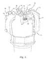
- FIG. 1is a top plan view of a drill bit 1 .
- FIG. 2is a side perspective view of the drill bit of FIG. 1 .
- FIG. 3is a side perspective partial cut-away view of the drill bit of FIG. 1 .
- FIGS. 4 and 5 A-Bare various views that conceptually illustrate a cross-section of a drill bit flute of a drill bit.
- FIGS. 6A-Bare diagrams that illustrate lines of constant flow in the drill bit flue model of the embodiments disclosed herein ( FIG. 6A ), and a standard drill bit flute ( FIG. 6B ).
- FIG. 7is a bottom plan view of the drill bit of FIG. 1 .
- FIG. 8is a diagram showing an annular segment corresponding to a drill bit flute present on the outer gage of the drill bit of FIG. 7 .
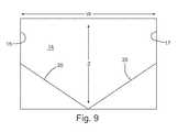
- FIG. 9shows a further cross-section of a flute.
- a drill bit head 10has a cutting end 11 formed of multiple cutting blades 12 .
- Each pair of adjacent cutting blades 12defines a flute 14 between the adjacent cutting blades 12 .
- the cutting blades 12 and flutes 14each extend radially outward from a central area of the drill bit head 10 . As the cutting blades 12 extend radially outward, they may be slightly curved.
- Each cutting blade 12has a front face 15 and a back face 17 .
- the front face 15is the face that faces forwards in the direction of rotation of the drill bit 10 in normal use and is the face that contains cutting elements.
- Each front face 15 of the cutting bladesincorporates cutting elements 16 .
- At least a nozzle 18is formed at the base of each flute 14 and is directed towards a cutting element 16 on the corresponding front face 15 that defines a side of the flute 14 in which the nozzle 18 is formed.
- Each flute 14defines a flow path for fluid moving along the flute in a flow direction. The flow from the nozzle 18 will flow across multiple cutting elements 16 as the flow expands outward from the nozzle, and the nozzle 18 will thus typically be directed at more than one of the cutting elements. Fluid is supplied to the nozzles 18 in conventional manner through a flow passage 13 that extends through the drill bit head 10 .
- the cutting elements 16may be conventional PDC cutters. There may also be more than one nozzle 18 in each flute 14 .
- Each flute 14has a base 20 , a depth Z (see also FIGS. 5A-5B ) and circumferential width W (see also FIGS. 5A-5B ) at a cutting element 16 towards which the respective nozzle 18 is directed.
- the depth Zis the maximum depth of the flute.
- Each flute 14has a cross-section in a plane perpendicular to the flow direction, thus also perpendicular to the base and to the front face at the cutting element 16 .
- the cross-section of the flute 14is defined by the depth Z and circumferential width W of the flute 14 .
- the cross-section of the flutethat is, the flow area of the flute, at a cutting element 16 is at least 15% smaller in area than the area of an annular segment having a constant radial depth and circumferential width equal to the depth Z and circumferential width W of the flute at the cutting element 16 .
- An annular segment S having a constant radial depth Z and width Wis shown in FIG. 8 along with the hatched cross-section A of a flute with a reduced cross-section.
- the reduced cross-sectionmay be achieved by having the base 20 of a flute 14 slope upward from the front face 15 to the back face 17 of the respective blades that define the flute 14 .
- the reduced cross-sectionincreases the flow velocity of the jet from the nozzle 18 across cutting elements 16 .
- the front face 15 of a blade 12is sloped inward, corresponding to the point of maximum depth being more centrally located within a flute 14 , the reduction in cross-section caused by the inward sloping cross-section is counted within the cross-section reduction.
- the front face 15may also slope inwards toward the flute gradually from the top of the blade or in sloped segments as illustrated in FIG.
- the flutehas a first portion that is rectangular (above the breaks in slope where the base 20 meets the front face 15 and back face 17 respectively) and a second portion that is triangular (below the breaks in slope).
- the flute 14 in any of these examplescould terminate at any point above the breaks in slope, and if the flute terminated at the breaks in slope, then the flute would be entirely triangular in shape. In practice, breaks would be smooth, so that the defined shapes are approximate.
- Each flute 14therefore defines a volume having cross-sections (see areas demarked by lines L 1 -L 6 for example in FIGS. 5A-5B ) perpendicular to the flow of fluid (exemplary flow shown by arrows 19 in FIG. 2 ) through the flute 14 .
- the flow area available in the cross sectionis compressed or moved closer towards the cutting element 16 .
- the deepest point of the flute 14may occur at the base of the front face 15 .
- the area of reduced cross-sectionpreferably extends along each flute 14 , in particular wherever a cutting element is present.
- FIG. 7looking at a PDC drill bit 10 from a bottom view the same concept is described at the break over from the flute 14 at the outer gage of the drill bit 10 , where the flute may become or transfers to a junk slot.
- the junk slotmay be designed with the same concepts in mind as the flutes disclosed herein.
- FIGS. 5A-5Bshow exemplary cross-sections of a flute 14 .
- the cross-sections in FIGS. 5A-5Bare simplified to rectangles, but represent real world annular segments as for example shown in FIG. 8 . That is, the straight line W corresponds to a circumferential curve between adjacent blades of a drill bit.
- the box of FIG. 4illustrates a flow channel along a flute that in practice is curved, both between the blades and along the flute. By narrowing the flute by inserting a sloped base, such as a diagonal base, the cross -sectional area is reduced, in the case of FIG. 4 by a factor of approximately 50%.
- a sloped basesuch as a diagonal base
- the sloped bases of the fluteare illustrated by lines L 1 -L 6 , each corresponding to a different cross-sectional reduction.
- the lines L 1 -L 3corresponds to essentially triangular cross-sections, while the lines L 4 -L 6 correspond to essentially trapezoidal cross-sections.
- the lines L 1 -L 6correspond to flow area reductions of 50%, 35%, 25%, 30%, 25% and 15% respectively. Other reductions are possible, such as 60%, 70%, 80% and 90% by increasing the slope of the base 20 as it extends away from the deepest point of the flute.
- FIGS. 6A and 6Billustrate that the streamlines (or the lines of constant fluid velocity) are arranged differently in a standard rectangular flute ( FIG. 6B ) to a flute within the embodiments disclosed herein ( FIG. 6A ). This is a result of the different cross-sectional areas, which will improve cutter cleaning with the new flute design. This may be mainly due to the properties of the drilling fluid being non-Newtonian in behavior.
- the typical rectangular cross-section( FIG. 6B ) has streamlines that are further apart, with no significant difference between the streamlines in front of a cutter blade or behind a cutter blade.
- the flute design in FIG. 6Ain addition to optionally having a higher average velocity, induces a more rapid velocity of fluid in front of the cutter blade (illustrated by D 2 ) compared with flow at the opposite side of the flute (illustrated by D 1 ), which improves the drill bit hydraulic and cleaning. This is illustrated by the fact that in FIG. 6A the distance between adjacent streamlines are closer together in front of the PDC cutter blade (D 2 ) versus in the back of the blade (D 1 ) where the streamlines are further apart.
- FIGS. 6A and 6BA higher velocity change in front of the cutter blade generates a more rapid removal of cuttings from the cutting element, in addition to providing better cooling to the cutters. Also shown in FIGS. 6A and 6B is the fact that in FIG. 6A , regardless of whether or not the flow area is reduced in size, the asymmetrical cross-section moves the center of gravity (COG) of the fluid flow closer to the cutting elements. Referring to FIG. 3 , the cutaway illustration demonstrates this point, as the sloped base 20 ensures that flow will be more turbulent and faster at the cutting elements 16 than if flute 14 had a standard design.
- COGcenter of gravity
Landscapes
- Engineering & Computer Science (AREA)
- Life Sciences & Earth Sciences (AREA)
- Geology (AREA)
- Mining & Mineral Resources (AREA)
- Mechanical Engineering (AREA)
- Physics & Mathematics (AREA)
- Environmental & Geological Engineering (AREA)
- Fluid Mechanics (AREA)
- General Life Sciences & Earth Sciences (AREA)
- Geochemistry & Mineralogy (AREA)
- Drilling Tools (AREA)
Abstract
Description
Claims (10)
Priority Applications (2)
| Application Number | Priority Date | Filing Date | Title |
|---|---|---|---|
| US12/628,956US8517124B2 (en) | 2009-12-01 | 2009-12-01 | PDC drill bit with flute design for better bit cleaning |
| US13/959,580US8899355B2 (en) | 2009-12-01 | 2013-08-05 | PDC drill bit with flute design for better bit cleaning |
Applications Claiming Priority (1)
| Application Number | Priority Date | Filing Date | Title |
|---|---|---|---|
| US12/628,956US8517124B2 (en) | 2009-12-01 | 2009-12-01 | PDC drill bit with flute design for better bit cleaning |
Related Child Applications (1)
| Application Number | Title | Priority Date | Filing Date |
|---|---|---|---|
| US13/959,580ContinuationUS8899355B2 (en) | 2009-12-01 | 2013-08-05 | PDC drill bit with flute design for better bit cleaning |
Publications (2)
| Publication Number | Publication Date |
|---|---|
| US20110127087A1 US20110127087A1 (en) | 2011-06-02 |
| US8517124B2true US8517124B2 (en) | 2013-08-27 |
Family
ID=44067992
Family Applications (2)
| Application Number | Title | Priority Date | Filing Date |
|---|---|---|---|
| US12/628,956Expired - Fee RelatedUS8517124B2 (en) | 2009-12-01 | 2009-12-01 | PDC drill bit with flute design for better bit cleaning |
| US13/959,580ActiveUS8899355B2 (en) | 2009-12-01 | 2013-08-05 | PDC drill bit with flute design for better bit cleaning |
Family Applications After (1)
| Application Number | Title | Priority Date | Filing Date |
|---|---|---|---|
| US13/959,580ActiveUS8899355B2 (en) | 2009-12-01 | 2013-08-05 | PDC drill bit with flute design for better bit cleaning |
Country Status (1)
| Country | Link |
|---|---|
| US (2) | US8517124B2 (en) |
Cited By (6)
| Publication number | Priority date | Publication date | Assignee | Title |
|---|---|---|---|---|
| US20170211334A1 (en)* | 2014-07-21 | 2017-07-27 | Schlumberger Technology Corporation | Reamer |
| US20170211333A1 (en)* | 2014-07-21 | 2017-07-27 | Schlumberger Technology Corporation | Downhole rotary cutting tool |
| US20170211335A1 (en)* | 2014-07-21 | 2017-07-27 | Schlumberger Technology Corporation | Reamer |
| US20170218707A1 (en)* | 2014-07-21 | 2017-08-03 | Schlumberger Technology Corporation | Reamer |
| US10508499B2 (en)* | 2014-07-21 | 2019-12-17 | Schlumberger Technology Corporation | Reamer |
| US20200056430A1 (en)* | 2018-08-16 | 2020-02-20 | Ulterra Drilling Technologies, L.P. | Downhole Tools with Improved Arrangements of Cutters |
Families Citing this family (9)
| Publication number | Priority date | Publication date | Assignee | Title |
|---|---|---|---|---|
| GB2520998B (en) | 2013-12-06 | 2016-06-29 | Schlumberger Holdings | Expandable Reamer |
| US11015394B2 (en)* | 2014-06-18 | 2021-05-25 | Ulterra Drilling Technologies, Lp | Downhole tool with fixed cutters for removing rock |
| US10233696B2 (en) | 2014-06-18 | 2019-03-19 | Ulterra Drilling Technologies, L.P. | Drill bit |
| WO2016014283A1 (en) | 2014-07-21 | 2016-01-28 | Schlumberger Canada Limited | Reamer |
| US11344975B2 (en)* | 2015-04-09 | 2022-05-31 | Siemens Energy, Inc. | Optically conductive filler for laser processing |
| CN110469270A (en)* | 2018-05-11 | 2019-11-19 | 成都百施特金刚石钻头有限公司 | A kind of PDC drill bit with anti-mud drum function |
| CN108661563A (en)* | 2018-05-16 | 2018-10-16 | 中国石油天然气集团有限公司 | Cutting tooth contains the PDC drill bit of fluid channel |
| CN114278230A (en)* | 2021-12-30 | 2022-04-05 | 库尔勒施得石油技术服务有限公司 | A reverse circulation drill |
| CN117569747B (en)* | 2024-01-16 | 2024-04-09 | 陕西星通石油工程技术有限公司 | Anti-balling PDC drill bit capable of removing chips rapidly |
Citations (44)
| Publication number | Priority date | Publication date | Assignee | Title |
|---|---|---|---|---|
| US3216514A (en) | 1962-02-23 | 1965-11-09 | Nelson Norman A | Rotary drilling apparatus |
| US3402780A (en)* | 1965-12-27 | 1968-09-24 | Gulf Research Development Co | Hydraulic jet drilling method |
| US3419094A (en)* | 1966-06-17 | 1968-12-31 | Reed Roller Bit Co | Drill string stabilizer |
| US3548959A (en)* | 1969-07-10 | 1970-12-22 | Gulf Research Development Co | Relief-type jet bits |
| US3610347A (en) | 1969-06-02 | 1971-10-05 | Nick D Diamantides | Vibratory drill apparatus |
| US3897836A (en) | 1973-10-18 | 1975-08-05 | Exotech | Apparatus for boring through earth formations |
| US4114705A (en) | 1976-05-26 | 1978-09-19 | Societe B.V.S. | Rock drilling tool having pulsed jets |
| US4185706A (en) | 1978-11-17 | 1980-01-29 | Smith International, Inc. | Rock bit with cavitating jet nozzles |
| GB2104942A (en) | 1981-08-31 | 1983-03-16 | Smith International | Rock bit with cavitation nozzle |
| US4494618A (en)* | 1982-09-30 | 1985-01-22 | Strata Bit Corporation | Drill bit with self cleaning nozzle |
| US4673045A (en) | 1984-08-16 | 1987-06-16 | Mccullough Doyle W | Enhanced circulation drill bit |
| US4775016A (en) | 1987-09-29 | 1988-10-04 | Hughes Tool Company - Usa | Downhole pressure fluctuating feedback system |
| US4819745A (en) | 1983-07-08 | 1989-04-11 | Intech Oil Tools Ltd | Flow pulsing apparatus for use in drill string |
| EP0333454A2 (en) | 1988-03-15 | 1989-09-20 | Hercules Incorporated | Manufacture of block polyester polyols, and polyurethanes derived therefrom |
| US5067655A (en) | 1987-12-11 | 1991-11-26 | Deutsche Forschungsanstalt Fuer Luft- Und Raumfahrt | Whirl nozzle for atomizing a liquid |
| US5197554A (en)* | 1988-10-20 | 1993-03-30 | Shell Internationale Research Maatschappij B.V. The Netherlands | Rotary drill bit for drilling through sticky formations |
| CA2121232A1 (en) | 1991-10-15 | 1993-04-29 | William Anthony Griffin | Pulsation nozzle, for self-excited oscillation of a drilling fluid jet stream |
| EP0370709B1 (en) | 1988-11-25 | 1994-07-13 | Intech International Inc. | Flow pulsing apparatus for drill string |
| US5538093A (en) | 1994-12-05 | 1996-07-23 | Smith International, Inc. | High flow weld-in nozzle sleeve for rock bits |
| US5678645A (en) | 1995-11-13 | 1997-10-21 | Baker Hughes Incorporated | Mechanically locked cutters and nozzles |
| US5775443A (en) | 1996-10-15 | 1998-07-07 | Nozzle Technology, Inc. | Jet pump drilling apparatus and method |
| US5862871A (en) | 1996-02-20 | 1999-01-26 | Ccore Technology & Licensing Limited, A Texas Limited Partnership | Axial-vortex jet drilling system and method |
| US5992763A (en) | 1997-08-06 | 1999-11-30 | Vortexx Group Incorporated | Nozzle and method for enhancing fluid entrainment |
| US6021858A (en)* | 1996-06-05 | 2000-02-08 | Smith International, Inc. | Drill bit having trapezium-shaped blades |
| US6062325A (en)* | 1997-04-21 | 2000-05-16 | Camco International (Uk) Limited | Rotary drill bits |
| US6079507A (en)* | 1996-04-12 | 2000-06-27 | Baker Hughes Inc. | Drill bits with enhanced hydraulic flow characteristics |
| US6082473A (en) | 1998-05-22 | 2000-07-04 | Dickey; Winton B. | Drill bit including non-plugging nozzle and method for removing cuttings from drilling tool |
| US6129161A (en)* | 1998-07-22 | 2000-10-10 | Camco International (Uk) Limited | Rotary drill bits with extended bearing surfaces |
| US6142248A (en) | 1998-04-02 | 2000-11-07 | Diamond Products International, Inc. | Reduced erosion nozzle system and method for the use of drill bits to reduce erosion |
| US6354387B1 (en) | 1999-02-25 | 2002-03-12 | Baker Hughes Incorporated | Nozzle orientation for roller cone rock bit |
| US20020092684A1 (en) | 2000-06-07 | 2002-07-18 | Smith International, Inc. | Hydro-lifter rock bit with PDC inserts |
| US20020148649A1 (en) | 2001-04-16 | 2002-10-17 | Dickey Winton B. | Three cone rock bit with multi-ported non-plugging center jet nozzle and method |
| US6470980B1 (en) | 1997-07-22 | 2002-10-29 | Rex A. Dodd | Self-excited drill bit sub |
| US20030010532A1 (en) | 2001-07-11 | 2003-01-16 | Kristiansen Steffen S. | Drill bit having adjustable total flow area |
| US6585063B2 (en) | 2000-12-14 | 2003-07-01 | Smith International, Inc. | Multi-stage diffuser nozzle |
| US20030192718A1 (en) | 2002-04-10 | 2003-10-16 | Buckman William G. | Nozzle for jet drilling |
| US6772849B2 (en) | 2001-10-25 | 2004-08-10 | Smith International, Inc. | Protective overlay coating for PDC drill bits |
| US6986297B2 (en) | 2000-01-31 | 2006-01-17 | Baker Hughes Incorporated | Method of manufacturing PDC cutters with chambers or passages |
| CA2557947A1 (en) | 2004-02-26 | 2007-02-28 | Smith International, Inc. | Improved nozzle bore for pdc bits |
| US20070221406A1 (en) | 2006-03-24 | 2007-09-27 | Hall David R | Jack Element for a Drill Bit |
| US7343987B2 (en) | 2003-04-16 | 2008-03-18 | Particle Drilling Technologies, Inc. | Impact excavation system and method with suspension flow control |
| US7398838B2 (en) | 2003-04-16 | 2008-07-15 | Particle Drilling Technologies, Inc. | Impact excavation system and method with two-stage inductor |
| US20080230278A9 (en)* | 2005-03-03 | 2008-09-25 | Carl Hoffmaster | Fixed cutter drill bit for abrasive applications |
| US20080314645A1 (en)* | 2007-06-22 | 2008-12-25 | Hall David R | Stiffened Blade for Shear-type Drill Bit |
- 2009
- 2009-12-01USUS12/628,956patent/US8517124B2/ennot_activeExpired - Fee Related
- 2013
- 2013-08-05USUS13/959,580patent/US8899355B2/enactiveActive
Patent Citations (53)
| Publication number | Priority date | Publication date | Assignee | Title |
|---|---|---|---|---|
| US3216514A (en) | 1962-02-23 | 1965-11-09 | Nelson Norman A | Rotary drilling apparatus |
| US3402780A (en)* | 1965-12-27 | 1968-09-24 | Gulf Research Development Co | Hydraulic jet drilling method |
| US3419094A (en)* | 1966-06-17 | 1968-12-31 | Reed Roller Bit Co | Drill string stabilizer |
| US3610347A (en) | 1969-06-02 | 1971-10-05 | Nick D Diamantides | Vibratory drill apparatus |
| US3548959A (en)* | 1969-07-10 | 1970-12-22 | Gulf Research Development Co | Relief-type jet bits |
| US3897836A (en) | 1973-10-18 | 1975-08-05 | Exotech | Apparatus for boring through earth formations |
| US4114705A (en) | 1976-05-26 | 1978-09-19 | Societe B.V.S. | Rock drilling tool having pulsed jets |
| US4185706A (en) | 1978-11-17 | 1980-01-29 | Smith International, Inc. | Rock bit with cavitating jet nozzles |
| GB2104942A (en) | 1981-08-31 | 1983-03-16 | Smith International | Rock bit with cavitation nozzle |
| US4494618A (en)* | 1982-09-30 | 1985-01-22 | Strata Bit Corporation | Drill bit with self cleaning nozzle |
| US4819745A (en) | 1983-07-08 | 1989-04-11 | Intech Oil Tools Ltd | Flow pulsing apparatus for use in drill string |
| US4673045A (en) | 1984-08-16 | 1987-06-16 | Mccullough Doyle W | Enhanced circulation drill bit |
| US4775016A (en) | 1987-09-29 | 1988-10-04 | Hughes Tool Company - Usa | Downhole pressure fluctuating feedback system |
| US5067655A (en) | 1987-12-11 | 1991-11-26 | Deutsche Forschungsanstalt Fuer Luft- Und Raumfahrt | Whirl nozzle for atomizing a liquid |
| EP0333454A2 (en) | 1988-03-15 | 1989-09-20 | Hercules Incorporated | Manufacture of block polyester polyols, and polyurethanes derived therefrom |
| US5197554A (en)* | 1988-10-20 | 1993-03-30 | Shell Internationale Research Maatschappij B.V. The Netherlands | Rotary drill bit for drilling through sticky formations |
| EP0370709B1 (en) | 1988-11-25 | 1994-07-13 | Intech International Inc. | Flow pulsing apparatus for drill string |
| US5495903A (en) | 1991-10-15 | 1996-03-05 | Pulse Ireland | Pulsation nozzle, for self-excited oscillation of a drilling fluid jet stream |
| EP0607135A1 (en) | 1991-10-15 | 1994-07-27 | Pulse Ireland | Pulsation nozzle for self-excited vibration of a drilling fluid jet flow. |
| CA2121232A1 (en) | 1991-10-15 | 1993-04-29 | William Anthony Griffin | Pulsation nozzle, for self-excited oscillation of a drilling fluid jet stream |
| US5538093A (en) | 1994-12-05 | 1996-07-23 | Smith International, Inc. | High flow weld-in nozzle sleeve for rock bits |
| US5678645A (en) | 1995-11-13 | 1997-10-21 | Baker Hughes Incorporated | Mechanically locked cutters and nozzles |
| US5906245A (en) | 1995-11-13 | 1999-05-25 | Baker Hughes Incorporated | Mechanically locked drill bit components |
| US5862871A (en) | 1996-02-20 | 1999-01-26 | Ccore Technology & Licensing Limited, A Texas Limited Partnership | Axial-vortex jet drilling system and method |
| US6079507A (en)* | 1996-04-12 | 2000-06-27 | Baker Hughes Inc. | Drill bits with enhanced hydraulic flow characteristics |
| US6021858A (en)* | 1996-06-05 | 2000-02-08 | Smith International, Inc. | Drill bit having trapezium-shaped blades |
| US5775443A (en) | 1996-10-15 | 1998-07-07 | Nozzle Technology, Inc. | Jet pump drilling apparatus and method |
| US6062325A (en)* | 1997-04-21 | 2000-05-16 | Camco International (Uk) Limited | Rotary drill bits |
| US6470980B1 (en) | 1997-07-22 | 2002-10-29 | Rex A. Dodd | Self-excited drill bit sub |
| US5992763A (en) | 1997-08-06 | 1999-11-30 | Vortexx Group Incorporated | Nozzle and method for enhancing fluid entrainment |
| US6142248A (en) | 1998-04-02 | 2000-11-07 | Diamond Products International, Inc. | Reduced erosion nozzle system and method for the use of drill bits to reduce erosion |
| US6082473A (en) | 1998-05-22 | 2000-07-04 | Dickey; Winton B. | Drill bit including non-plugging nozzle and method for removing cuttings from drilling tool |
| US6129161A (en)* | 1998-07-22 | 2000-10-10 | Camco International (Uk) Limited | Rotary drill bits with extended bearing surfaces |
| US6354387B1 (en) | 1999-02-25 | 2002-03-12 | Baker Hughes Incorporated | Nozzle orientation for roller cone rock bit |
| US6986297B2 (en) | 2000-01-31 | 2006-01-17 | Baker Hughes Incorporated | Method of manufacturing PDC cutters with chambers or passages |
| US20020092684A1 (en) | 2000-06-07 | 2002-07-18 | Smith International, Inc. | Hydro-lifter rock bit with PDC inserts |
| US6585063B2 (en) | 2000-12-14 | 2003-07-01 | Smith International, Inc. | Multi-stage diffuser nozzle |
| US7188682B2 (en) | 2000-12-14 | 2007-03-13 | Smith International, Inc. | Multi-stage diffuser nozzle |
| US20020148649A1 (en) | 2001-04-16 | 2002-10-17 | Dickey Winton B. | Three cone rock bit with multi-ported non-plugging center jet nozzle and method |
| US6581702B2 (en) | 2001-04-16 | 2003-06-24 | Winton B. Dickey | Three-cone rock bit with multi-ported non-plugging center jet nozzle and method |
| US20030010532A1 (en) | 2001-07-11 | 2003-01-16 | Kristiansen Steffen S. | Drill bit having adjustable total flow area |
| US6698538B2 (en)* | 2001-07-11 | 2004-03-02 | Smith International, Inc. | Drill bit having adjustable total flow area |
| US6772849B2 (en) | 2001-10-25 | 2004-08-10 | Smith International, Inc. | Protective overlay coating for PDC drill bits |
| US6668948B2 (en) | 2002-04-10 | 2003-12-30 | Buckman Jet Drilling, Inc. | Nozzle for jet drilling and associated method |
| US20030192718A1 (en) | 2002-04-10 | 2003-10-16 | Buckman William G. | Nozzle for jet drilling |
| US7343987B2 (en) | 2003-04-16 | 2008-03-18 | Particle Drilling Technologies, Inc. | Impact excavation system and method with suspension flow control |
| US7398838B2 (en) | 2003-04-16 | 2008-07-15 | Particle Drilling Technologies, Inc. | Impact excavation system and method with two-stage inductor |
| CA2557947A1 (en) | 2004-02-26 | 2007-02-28 | Smith International, Inc. | Improved nozzle bore for pdc bits |
| US7325632B2 (en) | 2004-02-26 | 2008-02-05 | Smith International, Inc. | Nozzle bore for PDC bits |
| US20080230278A9 (en)* | 2005-03-03 | 2008-09-25 | Carl Hoffmaster | Fixed cutter drill bit for abrasive applications |
| US20070221406A1 (en) | 2006-03-24 | 2007-09-27 | Hall David R | Jack Element for a Drill Bit |
| US20080314645A1 (en)* | 2007-06-22 | 2008-12-25 | Hall David R | Stiffened Blade for Shear-type Drill Bit |
| US7571782B2 (en) | 2007-06-22 | 2009-08-11 | Hall David R | Stiffened blade for shear-type drill bit |
Non-Patent Citations (1)
| Title |
|---|
| "Oil & Gas Well Drilling Bits: Diamond-Core-Carbide-Rock Drill Bit", Slimhole Drilling [online], http://www.slimhole.org/core-drill-bits-diamond-bit.htm, Dec. 2009. |
Cited By (11)
| Publication number | Priority date | Publication date | Assignee | Title |
|---|---|---|---|---|
| US20170211334A1 (en)* | 2014-07-21 | 2017-07-27 | Schlumberger Technology Corporation | Reamer |
| US20170211333A1 (en)* | 2014-07-21 | 2017-07-27 | Schlumberger Technology Corporation | Downhole rotary cutting tool |
| US20170211335A1 (en)* | 2014-07-21 | 2017-07-27 | Schlumberger Technology Corporation | Reamer |
| US20170218707A1 (en)* | 2014-07-21 | 2017-08-03 | Schlumberger Technology Corporation | Reamer |
| US10501995B2 (en)* | 2014-07-21 | 2019-12-10 | Schlumberger Technology Corporation | Reamer |
| US10508499B2 (en)* | 2014-07-21 | 2019-12-17 | Schlumberger Technology Corporation | Reamer |
| US10584538B2 (en)* | 2014-07-21 | 2020-03-10 | Schlumberger Technology Corporation | Reamer |
| US10612309B2 (en)* | 2014-07-21 | 2020-04-07 | Schlumberger Technology Corporation | Reamer |
| US10704332B2 (en)* | 2014-07-21 | 2020-07-07 | Schlumberger Technology Corporation | Downhole rotary cutting tool |
| US20200056430A1 (en)* | 2018-08-16 | 2020-02-20 | Ulterra Drilling Technologies, L.P. | Downhole Tools with Improved Arrangements of Cutters |
| US11028650B2 (en)* | 2018-08-16 | 2021-06-08 | Ulterra Drilling Technologies, L.P. | Downhole tools with improved arrangements of cutters |
Also Published As
| Publication number | Publication date |
|---|---|
| US20110127087A1 (en) | 2011-06-02 |
| US8899355B2 (en) | 2014-12-02 |
| US20140020957A1 (en) | 2014-01-23 |
Similar Documents
| Publication | Publication Date | Title |
|---|---|---|
| US8517124B2 (en) | PDC drill bit with flute design for better bit cleaning | |
| US10745973B2 (en) | Securing mechanism for a drilling element on a downhole drilling tool | |
| US5551522A (en) | Drill bit having stability enhancing cutting structure | |
| US8905162B2 (en) | High efficiency hydraulic drill bit | |
| US9267333B2 (en) | Impregnated bit with improved cutting structure and blade geometry | |
| US20080135297A1 (en) | Rotary drag bits having a pilot cutter configuraton and method to pre-fracture subterranean formations therewith | |
| BR112013020374B1 (en) | drill bit and downhole cutting tool | |
| US11428050B2 (en) | Reverse circulation hybrid bit | |
| US10125550B2 (en) | Orientation of cutting element at first radial position to cut core | |
| US20160177630A1 (en) | Extended or raised nozzle for pdc bits | |
| CA2686066C (en) | Pdc drill bit with flute design for better bit cleaning | |
| EP3363988B1 (en) | Impregnated drill bit including a planar blade profile along drill bit face | |
| US20040094334A1 (en) | Blunt faced cutter element and enhanced drill bit and cutting structure | |
| US9284785B2 (en) | Drill bits having depth of cut control features and methods of making and using the same | |
| US20130008724A1 (en) | Drill bit with distributed force profile | |
| CA2756956C (en) | Drill bit with enhanced hydraulics and erosion-shielded cutting teeth | |
| US20140076639A1 (en) | Rock Bit and Cutter Teeth Geometries | |
| US9617794B2 (en) | Feature to eliminate shale packing/shale evacuation channel | |
| US20190032411A1 (en) | Earth-boring tools including cutting element profiles configured to reduce work rates | |
| US11505998B2 (en) | Earth-boring tool geometry and cutter placement and associated apparatus and methods | |
| CN105378209A (en) | Drill bit | |
| US20090200081A1 (en) | Shear cutter drill bit |
Legal Events
| Date | Code | Title | Description |
|---|---|---|---|
| AS | Assignment | Owner name:NORTHBASIN ENERGY SERVICES INC., CANADA Free format text:ASSIGNMENT OF ASSIGNORS INTEREST;ASSIGNOR:HARELAND, GEIR;REEL/FRAME:026933/0518 Effective date:20091130 | |
| AS | Assignment | Owner name:NORTHBASIN ENERGY SERVICES INC., CANADA Free format text:ASSIGNMENT OF ASSIGNORS INTEREST;ASSIGNOR:JANZEN, JEFF;REEL/FRAME:030670/0390 Effective date:20130612 | |
| STCF | Information on status: patent grant | Free format text:PATENTED CASE | |
| REMI | Maintenance fee reminder mailed | ||
| FEPP | Fee payment procedure | Free format text:SURCHARGE FOR LATE PAYMENT, SMALL ENTITY (ORIGINAL EVENT CODE: M2554) | |
| MAFP | Maintenance fee payment | Free format text:PAYMENT OF MAINTENANCE FEE, 4TH YR, SMALL ENTITY (ORIGINAL EVENT CODE: M2551) Year of fee payment:4 | |
| FEPP | Fee payment procedure | Free format text:MAINTENANCE FEE REMINDER MAILED (ORIGINAL EVENT CODE: REM.); ENTITY STATUS OF PATENT OWNER: SMALL ENTITY | |
| FEPP | Fee payment procedure | Free format text:7.5 YR SURCHARGE - LATE PMT W/IN 6 MO, SMALL ENTITY (ORIGINAL EVENT CODE: M2555); ENTITY STATUS OF PATENT OWNER: SMALL ENTITY | |
| MAFP | Maintenance fee payment | Free format text:PAYMENT OF MAINTENANCE FEE, 8TH YR, SMALL ENTITY (ORIGINAL EVENT CODE: M2552); ENTITY STATUS OF PATENT OWNER: SMALL ENTITY Year of fee payment:8 | |
| AS | Assignment | Owner name:BITCO SERVICES LTD., CANADA Free format text:ASSIGNMENT OF ASSIGNORS INTEREST;ASSIGNOR:NORTHBASIN ENERGY SERVICES INC.;REEL/FRAME:061075/0878 Effective date:20150930 Owner name:KAMCO NORTH HOLDING COMPANY INC., CANADA Free format text:ASSIGNMENT OF ASSIGNORS INTEREST;ASSIGNOR:BITCO SERVICES LTD.;REEL/FRAME:061076/0032 Effective date:20170828 | |
| FEPP | Fee payment procedure | Free format text:MAINTENANCE FEE REMINDER MAILED (ORIGINAL EVENT CODE: REM.); ENTITY STATUS OF PATENT OWNER: SMALL ENTITY | |
| LAPS | Lapse for failure to pay maintenance fees | Free format text:PATENT EXPIRED FOR FAILURE TO PAY MAINTENANCE FEES (ORIGINAL EVENT CODE: EXP.); ENTITY STATUS OF PATENT OWNER: SMALL ENTITY | |
| STCH | Information on status: patent discontinuation | Free format text:PATENT EXPIRED DUE TO NONPAYMENT OF MAINTENANCE FEES UNDER 37 CFR 1.362 |