US8516634B2 - Bed structure with a deck section motion converter - Google Patents
Bed structure with a deck section motion converterDownload PDFInfo
- Publication number
- US8516634B2 US8516634B2US12/833,321US83332110AUS8516634B2US 8516634 B2US8516634 B2US 8516634B2US 83332110 AUS83332110 AUS 83332110AUS 8516634 B2US8516634 B2US 8516634B2
- Authority
- US
- United States
- Prior art keywords
- panel
- frame
- deck framework
- deck
- framework
- Prior art date
- Legal status (The legal status is an assumption and is not a legal conclusion. Google has not performed a legal analysis and makes no representation as to the accuracy of the status listed.)
- Active, expires
Links
Images


Classifications
- A—HUMAN NECESSITIES
- A61—MEDICAL OR VETERINARY SCIENCE; HYGIENE
- A61G—TRANSPORT, PERSONAL CONVEYANCES, OR ACCOMMODATION SPECIALLY ADAPTED FOR PATIENTS OR DISABLED PERSONS; OPERATING TABLES OR CHAIRS; CHAIRS FOR DENTISTRY; FUNERAL DEVICES
- A61G7/00—Beds specially adapted for nursing; Devices for lifting patients or disabled persons
- A61G7/002—Beds specially adapted for nursing; Devices for lifting patients or disabled persons having adjustable mattress frame
- A61G7/015—Beds specially adapted for nursing; Devices for lifting patients or disabled persons having adjustable mattress frame divided into different adjustable sections, e.g. for Gatch position
- A—HUMAN NECESSITIES
- A61—MEDICAL OR VETERINARY SCIENCE; HYGIENE
- A61G—TRANSPORT, PERSONAL CONVEYANCES, OR ACCOMMODATION SPECIALLY ADAPTED FOR PATIENTS OR DISABLED PERSONS; OPERATING TABLES OR CHAIRS; CHAIRS FOR DENTISTRY; FUNERAL DEVICES
- A61G7/00—Beds specially adapted for nursing; Devices for lifting patients or disabled persons
- A61G7/002—Beds specially adapted for nursing; Devices for lifting patients or disabled persons having adjustable mattress frame
- A61G7/018—Control or drive mechanisms
Definitions
- articulable supportssuch as hospital beds
- a supporthaving a deck framework, a deck panel connected to the framework and a motion converter for coordinating a translational motion of the panel with rotation and/or longitudinal translation of the framework.
- the teachings of the earlier applicationare presented in the context of a bed having three actuators for controlling motions of the upper body section.
- One of these actuatorscontrols the parallel translation.
- the other twoare operated to rotate the upper body section while concurrently translating it longitudinally, to rotate the upper body section without imparting any longitudinal translation, or to translate the upper body section longitudinally without imparting any rotation.
- beds produced for commercial salewill include fewer actuators for the upper body section.
- the applicationalso describes a bed with a simplified kinematic configuration having a single upper body section actuator and a dual rack and pinion. In operation the actuator extends or retracts to translate the upper body section longitudinally while changing its angular orientation. At the same time the dual rack and pinion effects the desired parallel translation of the upper body deck panel in response to the translation and orientation of the upper body section.
- a bed structureincludes a frame, a deck framework moveably connected to the frame, a panel moveably connected to the deck framework, and a motion converter.
- the motion convertertranslates the panel relative to the deck framework in response to either or both of a) relative translation between the deck framework and the frame, and b) relative rotation of the deck framework and the frame.
- the motion converterincludes a rack secured to the frame, a primary gear meshing with the rack, a panel drive sprocket rotatably mounted on the deck framework coaxially with the primary gear, an idler sprocket rotatably mounted on the deck framework remote from the panel drive sprocket, a slider connected to the panel, and a chain engaged with the panel drive sprocket and the idler and connected to the slider.
- FIG. 1is a schematic, side elevation view of a bed of the type used in hospitals and other health care facilities.
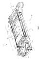
- FIG. 2is a perspective views of a bed structure as described herein with a frame and an upper body deck section, the deck section being shown at a horizontal angular orientation relative to the frame.
- FIG. 3is a view similar to that of FIG. 2 but with the deck section at an angular orientation of about 65 degrees relative to the frame.
- FIG. 4is a closer view of a portion of FIG. 3 showing, among other things, a gear rack, a split gear housing positioned at one end of the gear rack, and the lower extremity of the deck section and also having part of a deck section rail broken away to reveal a chain and a chain housing inside the rail.
- FIG. 5is a view of the gear rack seen in FIG. 4 but with a slide rail component of the gear rack broken away, with the gear housing at the other end of the gear rack and with certain elements, such as the deck section and one side of the split gear housing, removed.
- FIG. 6is a cross sectional view taken in direction 6 - 6 of FIG. 2 .
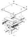
- FIGS. 7 and 8are exploded views showing components of the bed structure.
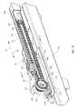
- FIG. 9-10are perspective views with selected components removed or broken away to reveal components such as a sprocket, the drive chain and a slider.
- FIG. 11is a cross sectional view taken in direction 11 - 11 of FIG. 10 showing the slider of FIGS. 9-10 in relation to a rail portion of the upper body deck section, a chain housing and a deck panel drive lug.
- FIG. 12is a perspective view showing a second slider in relation to the rail portion of the upper body deck section and a deck panel drive lug.
- FIG. 13is a side elevation view of a lift chain.
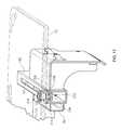
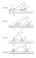
- FIG. 14is a schematic, side elevation view of a bed structure having a nontranslatable joint between a compression link and an elevatable frame of the bed.
- FIG. 15A-15Dare views similar to that of FIG. 14 showing the results of various modes of motion in an embodiment in which the joint between the compression link and the elevatable frame is longitudinally translatable.
- FIGS. 1-3show a hospital bed 10 extending longitudinally from a head end 12 to a foot end 14 and laterally from a left side 16 to a right side 18 .
- FIGS. 1-2also show a longitudinally extending centerline 22 .
- the bed structureincludes a base frame 26 and an elevatable frame 28 connected to the base frame by folding links 30 .
- the bedalso includes four deck sections: upper body section 34 , seat section 36 , thigh section 38 and calf section 40 , all connected to the elevatable frame.
- the upper body deck section 34includes a framework 50 comprising left and right hollow rails 52 , 54 joined to each other by an upper beam 56 and a lower beam 58 .
- First and second rail slots 60 , 62penetrate through and extend part way along the top of each rail.
- the lower end of each railalso includes a two sided mounting bracket 64 .
- the framework 50is moveably connected to elevatable frame 28 so that the framework is longitudinally translatable relative to the elevatable frame and is also rotatable about pivot axis 70 .
- Deck section 34also includes a deck panel 72 (shown in phantom) moveably connected to the framework 50 .
- panel 72is translatable relative to the framework in directions P 1 , P 2 parallel to the angular orientation ⁇ of the framework. This translation is the parallel translation referred to in the application summarized in the “Background” section of this application.
- the bedalso includes a pair of compression links 74 each having a frame end 76 pivotably connected to the elevatable frame at a frame joint 78 and a deck end 82 pivotably connected to the deck framework at a deck joint 84 .
- frame joint 78is not translatable relative to the frame, however in an alternate embodiment ( FIG. 15 ) joint 78 is longitudinally translatable relative to the frame.
- the bedalso includes a drive system which includes an actuator 90 having a deck end 92 connected to upper body deck framework 50 and a grounded end 94 connected to a suitable mechanical ground, such as elevatable frame 28 .
- the drive systemalso includes a motion converter, indicated generally by reference numeral 100 , for translating panel 72 relative to the deck framework in response to at least one of: a) relative translation between the deck framework and the frame, and b) relative rotation of the deck framework and the frame about axis 70 .
- the illustrated embodimentincludes both left and right motion converter units 100 L, 100 R. The units are mirror images of each other, hence it will suffice to describe only one of the units in more depth.
- FIGS. 4-8show components and construction of one of the motion converter units in more detail.
- the motion converterincludes a gear rack 102 affixed to elevatable frame 28 .
- the gear rackmay be considered to be a part of the elevatable frame.
- the illustrated rackcomprises a single piece slide rail 104 screwed to the frame and a rack plate 106 screwed to pedestals 108 at each end of the slide rail.
- a slot 110extends along the slide rail between the pedestals.
- the slide railhas laterally inboard and outboard sides 112 , 114 each with a shoulder 116 .
- the rack plateincludes openings 120 for receiving a gear tooth. The openings have a profile that conforms to the profile of the gear teeth.
- the motion converteralso includes a primary gear 124 in mesh with the rack plate.
- the gearhas a stub shaft 126 extending laterally away from bed centerline 22 .
- a pair of lugs 128projects laterally from the shaft.
- a split gear housing 130has a rectangularly shaped opening 132 extending through its base 134 , a cavity 136 inside the base and a tail 138 projecting from the base. The tail nests snugly in slide rail slot 110 , and the opening 132 embraces and fits snugly around rack plate 106 .
- An internal plate 140resides in the cavity. Screws 142 extend through a bearing plate 144 and a backing plate 146 and into the internal plate 140 to slidingly clamp the housing to the slide rail with the bearing plate abutting rail shoulder 116 .
- the primary gearis rotatably mounted inside gear housing 130 by way of inboard and outboard gear bushings 154 , 156 and a laterally extending pivot axle 158 .
- the pivot axlealso extends through holes 162 in the rail mounting bracket 64 to connect the primary gear to the deck framework. Bearings 164 nest in the holes 162 and circumscribe pivot axle 158 .
- the motion converteralso includes a deck panel rotary drive element such as a panel drive sprocket 170 .
- the sprocketresides inside a chain housing 172 located adjacent to and outboard of the gear housing 130 .
- the sprocketis rotatably mounted on pivot axle 158 by way of outboard gear bushing 156 .
- the sprockethas a stub shaft 174 extending laterally toward bed centerline 22 . Notches 176 at the inboard tip of the stub shaft mate with lugs 128 on the primary gear stub shaft to rotatably connect the sprocket to the primary gear.
- the sprocket and the primary gearare thus coaxial and mutually corotatable.
- the pitch diameters of the primary gear and the sprocketare 37.0 and 42.6 mm respectively. Accordingly, the primary gear and sprocket exhibit a non-unity drive ratio, specifically a drive ratio of about 1.15.
- the chain housing 172extends into the hollow interior of the framework (i.e. into rail 52 ).
- the chain housingincludes an internal track or ledge 182 , a shoulder 184 , and an elongated slot 186 that registers with first slot 60 in the framework rail.
- An idler sprocket 192is rotatably mounted inside the chain housing at its remote end 194 . Because the chain housing is stationary with respect to the deck framework 50 , the idler can be considered to be mounted on the framework.
- a slider 200includes a slide link 202 translatably supported on housing internal track 182 , and a slide block 204 bolted to the slide link.
- the slide linkhas a ledge 206 that abuts chain housing shoulder 184 to trap the slide link in the chain housing 172 .
- the slide blockincludes a head portion 208 that overlies the top of framework rail 50 on either side of first rail slot 60 and a neck portion 210 that projects through the rail slot and extends to the slide link.
- the slideralso includes a drive lug 218 projecting from the slide block. The drive lug is connected to deck panel 72 , thereby connecting the slider to the panel.
- a second slider 212comprises a second slide block 214 having a head portion 226 and a neck portion 228 .
- the second slideralso includes a retainer plate 230 .
- Head portion 226 of slide block 214overlies the top of framework rail 52 on either side of second rail slot 62 .
- Neck portion 228projects through rail slot 62 and extends to the retainer plate.
- the slide block and retainer plateare bolted together so that the lateral sides of the retainer plate reside under the interior of framework rail 52 on either side of second rail slot 62 and so that the slider can slide longitudinally along the length of the slot.
- a drive lug 218is connected to deck panel 72 , thereby connecting the slider to the panel.
- a roller chain 220loops around each sprocket 170 , 192 and engages with the sprocket teeth.
- the ends of the chainare connected to opposite ends of the slide link 202 , thereby also connecting the chain to the deck panel 72 .
- the chainis a linear or translatable drive element insofar as the part of the chain that extends linearly between the sprockets translates in direction P 1 or P 2 during operation of the drive system.
- Other kinematically equivalent devicescould be used in lieu of roller chain 220 .
- a lift chainone example of which is seen in FIG. 13 , could serve as a translatable drive element.
- the primary gearis operatively connected to the deck panel 72 .
- actuator 90extends and pushes framework beam 58 longitudinally toward the head end 12 of the bed.
- the compression link 74rotates clockwise to change the angular orientation ⁇ of the upper body deck framework.
- the longitudinal translation of the framework relative to the elevatable framecauses primary gear 124 to rotate in a clockwise direction as seen in FIGS. 5 , 8 , 9 and 10 .
- the primary geardrives the panel drive sprocket 170 in the same rotational sense.
- the sprocketdrives the chain which acts on slider 200 to translate deck panel 72 in direction P 1 relative to deck framework 50 . Retraction of the actuator reverses the above described motion to translate the deck panel in direction P 2 .
- the kinematic interaction between the gear rack 102 and the primary gear 124serves as a means for converting the relative translation and/or rotation between the deck framework and the elevatable frame to a rotary motion of primary gear 124 .
- the kinematic interaction between sprocket 170 and chain 220serves as a means for converting the rotary motion to a translational motion.
- the slider 200 and lug 218serve as a means for conveying the translational motion of the chain to the panel.
- FIG. 14is a simple schematic view showing the kinematic relationship of the actuator 90 , elevatable frame 28 , deck framework 50 and compression link 74 of the above described bed structure.
- Joint 78is non-translatable relative to frame 28 .
- operation of actuator 90causes deck panel 72 to translate longitudinally relative to the elevatable frame by a distance D and to rotate relative to the elevatable frame through an angle ⁇ .
- joint 78is longitudinally translatable relative to the frame by the action of second actuator 222 .
- deck framework 50can be translated longitudinally relative to the elevatable frame 28 without any rotation of the framework ( FIG.
- FIG. 15Brotated relative to the elevatable frame without any translation ( FIG. 15C ) or rotated and translated as in the first embodiment ( FIG. 15D ).
- second actuator 222introduces additional complexity, it also introduces additional flexibility that may be desirable. Because the motion converter described herein is responsive to relative motion between the frame and the deck framework irrespective of whether that relative motion is translation, rotation, or a combination thereof, it is equally applicable to the embodiments of both FIGS. 14 and 15 .
- kinematic equivalents of various components of the motion convertercan be used in lieu of the illustrated components.
- belts and pulleyscan be used instead of chain 220 and sprockets 170 , 192 ; a notched or toothed belt and mating gears can also be substituted for the chain and sprockets; a roller and a track with a high coefficient of friction (to prevent roller skidding) might be substituted for the gear 124 and rack 102 .
Landscapes
- Health & Medical Sciences (AREA)
- Nursing (AREA)
- Life Sciences & Earth Sciences (AREA)
- Animal Behavior & Ethology (AREA)
- General Health & Medical Sciences (AREA)
- Public Health (AREA)
- Veterinary Medicine (AREA)
- Invalid Beds And Related Equipment (AREA)
Abstract
Description
Claims (26)
Priority Applications (9)
| Application Number | Priority Date | Filing Date | Title |
|---|---|---|---|
| US12/833,321US8516634B2 (en) | 2010-07-09 | 2010-07-09 | Bed structure with a deck section motion converter |
| PCT/US2011/043392WO2012006545A2 (en) | 2010-07-09 | 2011-07-08 | Person support systems, devices, and methods |
| EP17164865.2AEP3210586B1 (en) | 2010-07-09 | 2011-07-08 | Fluid tank receptacle for person support systems |
| EP11804417.1AEP2590610B1 (en) | 2010-07-09 | 2011-07-08 | Person support systems, devices, and methods |
| JP2013518864AJP5986077B2 (en) | 2010-07-09 | 2011-07-08 | User retention system, apparatus, and method |
| AU2011274503AAU2011274503A1 (en) | 2010-07-09 | 2011-07-08 | Person support systems, devices, and methods |
| US14/176,188US9060619B2 (en) | 2010-07-09 | 2014-02-10 | Variable height siderail |
| US14/269,492US9333134B2 (en) | 2010-07-09 | 2014-05-05 | Medical gas tank receptacle for patient support apparatus |
| JP2015136793AJP2015211871A (en) | 2010-07-09 | 2015-07-08 | User support system, apparatus, and method |
Applications Claiming Priority (1)
| Application Number | Priority Date | Filing Date | Title |
|---|---|---|---|
| US12/833,321US8516634B2 (en) | 2010-07-09 | 2010-07-09 | Bed structure with a deck section motion converter |
Publications (2)
| Publication Number | Publication Date |
|---|---|
| US20120005832A1 US20120005832A1 (en) | 2012-01-12 |
| US8516634B2true US8516634B2 (en) | 2013-08-27 |
Family
ID=45437482
Family Applications (1)
| Application Number | Title | Priority Date | Filing Date |
|---|---|---|---|
| US12/833,321Active2031-06-20US8516634B2 (en) | 2010-07-09 | 2010-07-09 | Bed structure with a deck section motion converter |
Country Status (1)
| Country | Link |
|---|---|
| US (1) | US8516634B2 (en) |
Cited By (9)
| Publication number | Priority date | Publication date | Assignee | Title |
|---|---|---|---|---|
| US20140115785A1 (en)* | 2012-11-01 | 2014-05-01 | Hill-Rom Services, Inc. | Person support apparatus with spring assistance for articulation |
| US9101516B2 (en) | 2003-03-11 | 2015-08-11 | Stryker Corporation | Steerable ultra-low patient bed |
| WO2017087452A1 (en) | 2015-11-16 | 2017-05-26 | Hill-Rom Services, Inc. | Incontinence detection systems for hospital beds |
| US10130536B2 (en) | 2013-09-06 | 2018-11-20 | Stryker Corporation | Patient support usable with bariatric patients |
| EP3403580A1 (en) | 2017-05-16 | 2018-11-21 | Hill-Rom Services, Inc. | Incontinence detection apparatus electrical architecture |
| US10188569B2 (en) | 2013-09-06 | 2019-01-29 | Stryker Corporation | Patient support usable with bariatric patients |
| EP3598782A1 (en) | 2018-07-20 | 2020-01-22 | Hill-Rom Services, Inc. | Incontinence detection pad validation apparatus |
| US10842701B2 (en) | 2016-10-14 | 2020-11-24 | Stryker Corporation | Patient support apparatus with stabilization |
| US11229563B2 (en) | 2014-08-27 | 2022-01-25 | Umano Medical Inc. | Support panel pivoting system for a patient support device |
Families Citing this family (25)
| Publication number | Priority date | Publication date | Assignee | Title |
|---|---|---|---|---|
| US9295433B2 (en) | 2005-02-22 | 2016-03-29 | Roger P. Jackson | Synchronized patient elevation and positioning apparatus for use with patient positioning support systems |
| US7739762B2 (en) | 2007-10-22 | 2010-06-22 | Mizuho Orthopedic Systems, Inc. | Surgery table apparatus |
| US7565708B2 (en) | 2005-02-22 | 2009-07-28 | Jackson Roger P | Patient positioning support structure |
| US9186291B2 (en) | 2005-02-22 | 2015-11-17 | Roger P. Jackson | Patient positioning support structure with trunk translator |
| US9468576B2 (en) | 2005-02-22 | 2016-10-18 | Roger P. Jackson | Patient support apparatus with body slide position digitally coordinated with hinge angle |
| US20150059094A1 (en) | 2005-02-22 | 2015-03-05 | Roger P. Jackson | Patient positioning support structure |
| US9744087B2 (en) | 2005-02-22 | 2017-08-29 | Roger P. Jackson | Patient support apparatus with body slide position digitally coordinated with hinge angle |
| US9642760B2 (en) | 2006-05-05 | 2017-05-09 | Roger P. Jackson | Patient positioning support apparatus with virtual pivot-shift pelvic pads, upper body stabilization and fail-safe table attachment mechanism |
| US10869798B2 (en) | 2006-05-05 | 2020-12-22 | Warsaw Orthopedic, Inc. | Patient positioning support apparatus with virtual pivot-shift pelvic pads, upper body stabilization and fail-safe table attachment mechanism |
| WO2013058806A1 (en) | 2011-10-17 | 2013-04-25 | Jackson Roger P | Patient positioning support structure |
| US9561145B2 (en) | 2012-02-07 | 2017-02-07 | Roger P. Jackson | Fail-safe release mechanism for use with patient positioning support apparati |
| US9228885B2 (en) | 2012-06-21 | 2016-01-05 | Hill-Rom Services, Inc. | Patient support systems and methods of use |
| JP6017686B2 (en) | 2012-06-21 | 2016-11-02 | ヒル−ロム サービシズ,インコーポレイテッド | Patient holding system and method of use |
| US9833369B2 (en) | 2012-06-21 | 2017-12-05 | Hill-Rom Services, Inc. | Patient support systems and methods of use |
| US12011399B2 (en) | 2013-08-28 | 2024-06-18 | Warsaw Orthopedic, Inc. | Patient positioning support apparatus with fail-safe connector attachment mechanism |
| CN103637888B (en)* | 2013-11-27 | 2016-08-17 | 吴琼 | A kind of motion sensing control sick bed mobile system |
| US9549863B2 (en) | 2014-07-07 | 2017-01-24 | Roger P. Jackson | Surgical table with pivoting and translating hinge |
| US9402775B2 (en) | 2014-07-07 | 2016-08-02 | Roger P. Jackson | Single and dual column patient positioning and support structure |
| US10058468B2 (en) | 2014-08-28 | 2018-08-28 | Umano Medical Inc. | Siderail system for a bed |
| US10504353B2 (en) | 2015-07-27 | 2019-12-10 | Hill-Rom Services, Inc. | Customized bed exit warnings to modify patient behavior |
| EP3189823B1 (en) | 2016-01-07 | 2020-12-16 | Hill-Rom Services, Inc. | Support surface useful life monitoring |
| CN110294006A (en)* | 2018-03-21 | 2019-10-01 | 朴莲花 | Solar panels transport device |
| US20200375828A1 (en) | 2019-05-30 | 2020-12-03 | Hill-Rom Services, Inc. | Patient support interface device |
| CN112535589A (en)* | 2020-12-15 | 2021-03-23 | 康辉医疗科技(苏州)有限公司 | Electric nursing bed |
| CN115682038A (en)* | 2021-07-27 | 2023-02-03 | 芜湖美的智能厨电制造有限公司 | Integrated kitchen range |
Citations (13)
| Publication number | Priority date | Publication date | Assignee | Title |
|---|---|---|---|---|
| US3302219A (en)* | 1966-01-14 | 1967-02-07 | Joe F Harris | Hospital bed and lifting and turning device |
| US3729751A (en)* | 1971-04-26 | 1973-05-01 | W Kirkman | Paraplegic bed |
| US4685159A (en)* | 1985-05-09 | 1987-08-11 | Hans Oetiker | Hospital bed |
| US5404604A (en)* | 1991-06-14 | 1995-04-11 | Koninklijke Auping B.V. | Adjusting device for a bed or chair |
| US5870784A (en)* | 1994-03-15 | 1999-02-16 | Maxwell Products, Inc. | Adjustable articulated bed |
| US20010011394A1 (en)* | 1998-08-07 | 2001-08-09 | Heimbrock Richard H. | OB/GYN stretcher |
| US6578215B1 (en)* | 2000-09-29 | 2003-06-17 | Hill-Rom Services, Inc. | Surgery stretcher |
| US6978501B2 (en)* | 1995-01-31 | 2005-12-27 | Kci Licensing, Inc. | Bariatric bed apparatus and methods |
| US20080250562A1 (en)* | 2003-02-05 | 2008-10-16 | Tekulve Daniel R | Articulating bed frame |
| US7698761B2 (en) | 2008-02-04 | 2010-04-20 | L&P Property Management Company | Adjustable bed having four linear actuators |
| US20100122415A1 (en)* | 2008-11-17 | 2010-05-20 | Turner Jonathan D | Anthropometrically Governed Occupant Support |
| US8042210B2 (en)* | 2009-02-08 | 2011-10-25 | Alain Clenet | Articulating bed system |
| WO2012006545A2 (en) | 2010-07-09 | 2012-01-12 | Hill-Rom Services, Inc. | Person support systems, devices, and methods |
- 2010
- 2010-07-09USUS12/833,321patent/US8516634B2/enactiveActive
Patent Citations (14)
| Publication number | Priority date | Publication date | Assignee | Title |
|---|---|---|---|---|
| US3302219A (en)* | 1966-01-14 | 1967-02-07 | Joe F Harris | Hospital bed and lifting and turning device |
| US3729751A (en)* | 1971-04-26 | 1973-05-01 | W Kirkman | Paraplegic bed |
| US4685159A (en)* | 1985-05-09 | 1987-08-11 | Hans Oetiker | Hospital bed |
| US5404604A (en)* | 1991-06-14 | 1995-04-11 | Koninklijke Auping B.V. | Adjusting device for a bed or chair |
| US5870784A (en)* | 1994-03-15 | 1999-02-16 | Maxwell Products, Inc. | Adjustable articulated bed |
| US6978501B2 (en)* | 1995-01-31 | 2005-12-27 | Kci Licensing, Inc. | Bariatric bed apparatus and methods |
| US20010011394A1 (en)* | 1998-08-07 | 2001-08-09 | Heimbrock Richard H. | OB/GYN stretcher |
| US6578215B1 (en)* | 2000-09-29 | 2003-06-17 | Hill-Rom Services, Inc. | Surgery stretcher |
| US20080250562A1 (en)* | 2003-02-05 | 2008-10-16 | Tekulve Daniel R | Articulating bed frame |
| US7698761B2 (en) | 2008-02-04 | 2010-04-20 | L&P Property Management Company | Adjustable bed having four linear actuators |
| US20100122415A1 (en)* | 2008-11-17 | 2010-05-20 | Turner Jonathan D | Anthropometrically Governed Occupant Support |
| US8042210B2 (en)* | 2009-02-08 | 2011-10-25 | Alain Clenet | Articulating bed system |
| WO2012006545A2 (en) | 2010-07-09 | 2012-01-12 | Hill-Rom Services, Inc. | Person support systems, devices, and methods |
| WO2012006545A9 (en) | 2010-07-09 | 2013-04-18 | Hill-Rom Services, Inc. | Person support systems, devices, and methods |
Non-Patent Citations (3)
| Title |
|---|
| International Search Report; Date of Completion of International Search Report-Feb. 13, 2012; Mailing Date-Feb. 28, 2012; Authorized Officer-Blaine R. Copenheaver; International Application No. PCT/US2011/043392; International Filing Date Jul. 8, 2011; Applicant-Hill-Rom Services, Inc. |
| Notification of Transmittal of the International Search Report and The Written Opinon of the International Searching Authority, or the Declaration; International Application No. PCT/US2011/043392; International Filing Date Jul. 8, 2011; Mailing Date-Feb. 28, 2012; Applicant-Hill-Rom Services, Inc. |
| Written Opinion of the International Searching Authority; Date of Completion of Opinion-Feb. 13, 2012; Mailing Date-Feb. 28, 2012; Authorized Officer-Blaine R. Copenheaver; International Application No. PCT/US2011/043392; International Filing Date Jul. 8, 2011; Applicant-Hill-Rom Services, Inc. |
Cited By (17)
| Publication number | Priority date | Publication date | Assignee | Title |
|---|---|---|---|---|
| US9101516B2 (en) | 2003-03-11 | 2015-08-11 | Stryker Corporation | Steerable ultra-low patient bed |
| US9833368B2 (en)* | 2012-11-01 | 2017-12-05 | Hill-Rom Services, Inc. | Person support apparatus with spring assistance for articulation |
| US20140115785A1 (en)* | 2012-11-01 | 2014-05-01 | Hill-Rom Services, Inc. | Person support apparatus with spring assistance for articulation |
| US10716722B2 (en) | 2013-09-06 | 2020-07-21 | Stryker Corporation | Patient support usable with bariatric patients |
| US11865056B2 (en) | 2013-09-06 | 2024-01-09 | Stryker Corporation | Patient support usable with bariatric patients |
| US11980580B2 (en) | 2013-09-06 | 2024-05-14 | Stryker Corporation | Patient support usable with bariatric patients |
| US10188569B2 (en) | 2013-09-06 | 2019-01-29 | Stryker Corporation | Patient support usable with bariatric patients |
| US10842694B2 (en) | 2013-09-06 | 2020-11-24 | Stryker Corporation | Patient support usable with bariatric patients |
| US10130536B2 (en) | 2013-09-06 | 2018-11-20 | Stryker Corporation | Patient support usable with bariatric patients |
| US11285061B2 (en) | 2013-09-06 | 2022-03-29 | Stryker Corporation | Patient support usable with bariatric patients |
| US11419776B2 (en) | 2013-09-06 | 2022-08-23 | Stryker Corporation | Patient support usable with bariatric patients |
| US11938069B2 (en) | 2014-08-27 | 2024-03-26 | Umano Medical Inc. | Support panel pivoting system for a patient support device |
| US11229563B2 (en) | 2014-08-27 | 2022-01-25 | Umano Medical Inc. | Support panel pivoting system for a patient support device |
| WO2017087452A1 (en) | 2015-11-16 | 2017-05-26 | Hill-Rom Services, Inc. | Incontinence detection systems for hospital beds |
| US10842701B2 (en) | 2016-10-14 | 2020-11-24 | Stryker Corporation | Patient support apparatus with stabilization |
| EP3403580A1 (en) | 2017-05-16 | 2018-11-21 | Hill-Rom Services, Inc. | Incontinence detection apparatus electrical architecture |
| EP3598782A1 (en) | 2018-07-20 | 2020-01-22 | Hill-Rom Services, Inc. | Incontinence detection pad validation apparatus |
Also Published As
| Publication number | Publication date |
|---|---|
| US20120005832A1 (en) | 2012-01-12 |
Similar Documents
| Publication | Publication Date | Title |
|---|---|---|
| US8516634B2 (en) | Bed structure with a deck section motion converter | |
| EP2590610B1 (en) | Person support systems, devices, and methods | |
| RU2443405C2 (en) | Rotating device | |
| US20220287895A1 (en) | Belt driven width expansion of a bed | |
| CN102413768B (en) | Bed for medical imaging apparatus | |
| US5013018A (en) | Table positioning for X-ray examinations in plurality of positions | |
| US4984774A (en) | Patient support couch assembly | |
| EP2948371B1 (en) | Compact seat kinematic | |
| US20090236487A1 (en) | Platform Telescoping Mechanism | |
| CN201256177Y (en) | Built-in over 360 deg. Limited azimuth radar antenna seat | |
| US20180000675A1 (en) | Patient Support Systems With Rotary Actuators Having Cycloidal Drives | |
| US20080086816A1 (en) | Patient positioning system | |
| US20180000673A1 (en) | Patient Support Systems With Rotary Actuators | |
| JPH0482547A (en) | Bed for patient unable to move | |
| CN1264564A (en) | Regulator for chair or sofa, especially bedstead | |
| CN112545656A (en) | Terminal drive structure of compact endoscope operation robot | |
| US5273520A (en) | Mobilizing splint with reversible motorization assembly | |
| KR20140115183A (en) | Moving apparatus of operating table for medical care and operating table with it | |
| CN111759631A (en) | Sick bed structure and have its medical equipment | |
| CN104367345B (en) | A kind of ultrasonic probe assembly | |
| EP0669122B1 (en) | Multipurpose sickbed | |
| CN202891958U (en) | Arm C structure | |
| CN214164970U (en) | Automatic pedal device and system for filling gaps of subway platform | |
| CN108938269A (en) | A kind of dipping bath in-out apparatus with security implementations | |
| CN113331816B (en) | Medical human nuclear magnetism inspection device |
Legal Events
| Date | Code | Title | Description |
|---|---|---|---|
| AS | Assignment | Owner name:HILL-ROM SERVICES, INC., DELAWARE Free format text:ASSIGNMENT OF ASSIGNORS INTEREST;ASSIGNORS:TURNER, JONATHAN D;REINKE, CHRISTIAN H;REEL/FRAME:024688/0923 Effective date:20100709 | |
| AS | Assignment | Owner name:HILL-ROM SERVICES, INC. (INDIANA CORPORATION), IND Free format text:CHANGE OF STATE OF INCORPORATION FROM DELAWARE TO INDIANA;ASSIGNOR:HILL-ROM SERVICES, INC. (DELAWARE CORPORATION);REEL/FRAME:030832/0238 Effective date:20101231 | |
| STCF | Information on status: patent grant | Free format text:PATENTED CASE | |
| AS | Assignment | Owner name:JPMORGAN CHASE BANK, N.A., AS COLLATERAL AGENT, ILLINOIS Free format text:SECURITY INTEREST;ASSIGNORS:ALLEN MEDICAL SYSTEMS, INC.;HILL-ROM SERVICES, INC.;ASPEN SURGICAL PRODUCTS, INC.;AND OTHERS;REEL/FRAME:036582/0123 Effective date:20150908 Owner name:JPMORGAN CHASE BANK, N.A., AS COLLATERAL AGENT, IL Free format text:SECURITY INTEREST;ASSIGNORS:ALLEN MEDICAL SYSTEMS, INC.;HILL-ROM SERVICES, INC.;ASPEN SURGICAL PRODUCTS, INC.;AND OTHERS;REEL/FRAME:036582/0123 Effective date:20150908 | |
| AS | Assignment | Owner name:JPMORGAN CHASE BANK, N.A., AS COLLATERAL AGENT, ILLINOIS Free format text:SECURITY AGREEMENT;ASSIGNORS:HILL-ROM SERVICES, INC.;ASPEN SURGICAL PRODUCTS, INC.;ALLEN MEDICAL SYSTEMS, INC.;AND OTHERS;REEL/FRAME:040145/0445 Effective date:20160921 Owner name:JPMORGAN CHASE BANK, N.A., AS COLLATERAL AGENT, IL Free format text:SECURITY AGREEMENT;ASSIGNORS:HILL-ROM SERVICES, INC.;ASPEN SURGICAL PRODUCTS, INC.;ALLEN MEDICAL SYSTEMS, INC.;AND OTHERS;REEL/FRAME:040145/0445 Effective date:20160921 | |
| FPAY | Fee payment | Year of fee payment:4 | |
| AS | Assignment | Owner name:HILL-ROM SERVICES, INC., ILLINOIS Free format text:RELEASE BY SECURED PARTY;ASSIGNOR:JPMORGAN CHASE BANK, N.A.;REEL/FRAME:050254/0513 Effective date:20190830 Owner name:WELCH ALLYN, INC., NEW YORK Free format text:RELEASE BY SECURED PARTY;ASSIGNOR:JPMORGAN CHASE BANK, N.A.;REEL/FRAME:050254/0513 Effective date:20190830 Owner name:ANODYNE MEDICAL DEVICE, INC., FLORIDA Free format text:RELEASE BY SECURED PARTY;ASSIGNOR:JPMORGAN CHASE BANK, N.A.;REEL/FRAME:050254/0513 Effective date:20190830 Owner name:VOALTE, INC., FLORIDA Free format text:RELEASE BY SECURED PARTY;ASSIGNOR:JPMORGAN CHASE BANK, N.A.;REEL/FRAME:050254/0513 Effective date:20190830 Owner name:MORTARA INSTRUMENT SERVICES, INC., WISCONSIN Free format text:RELEASE BY SECURED PARTY;ASSIGNOR:JPMORGAN CHASE BANK, N.A.;REEL/FRAME:050254/0513 Effective date:20190830 Owner name:HILL-ROM, INC., ILLINOIS Free format text:RELEASE BY SECURED PARTY;ASSIGNOR:JPMORGAN CHASE BANK, N.A.;REEL/FRAME:050254/0513 Effective date:20190830 Owner name:HILL-ROM COMPANY, INC., ILLINOIS Free format text:RELEASE BY SECURED PARTY;ASSIGNOR:JPMORGAN CHASE BANK, N.A.;REEL/FRAME:050254/0513 Effective date:20190830 Owner name:ALLEN MEDICAL SYSTEMS, INC., ILLINOIS Free format text:RELEASE BY SECURED PARTY;ASSIGNOR:JPMORGAN CHASE BANK, N.A.;REEL/FRAME:050254/0513 Effective date:20190830 Owner name:MORTARA INSTRUMENT, INC., WISCONSIN Free format text:RELEASE BY SECURED PARTY;ASSIGNOR:JPMORGAN CHASE BANK, N.A.;REEL/FRAME:050254/0513 Effective date:20190830 | |
| AS | Assignment | Owner name:JPMORGAN CHASE BANK, N.A., ILLINOIS Free format text:SECURITY AGREEMENT;ASSIGNORS:HILL-ROM HOLDINGS, INC.;HILL-ROM, INC.;HILL-ROM SERVICES, INC.;AND OTHERS;REEL/FRAME:050260/0644 Effective date:20190830 | |
| MAFP | Maintenance fee payment | Free format text:PAYMENT OF MAINTENANCE FEE, 8TH YEAR, LARGE ENTITY (ORIGINAL EVENT CODE: M1552); ENTITY STATUS OF PATENT OWNER: LARGE ENTITY Year of fee payment:8 | |
| AS | Assignment | Owner name:HILL-ROM HOLDINGS, INC., ILLINOIS Free format text:RELEASE OF SECURITY INTEREST AT REEL/FRAME 050260/0644;ASSIGNOR:JPMORGAN CHASE BANK, N.A.;REEL/FRAME:058517/0001 Effective date:20211213 Owner name:BARDY DIAGNOSTICS, INC., ILLINOIS Free format text:RELEASE OF SECURITY INTEREST AT REEL/FRAME 050260/0644;ASSIGNOR:JPMORGAN CHASE BANK, N.A.;REEL/FRAME:058517/0001 Effective date:20211213 Owner name:VOALTE, INC., FLORIDA Free format text:RELEASE OF SECURITY INTEREST AT REEL/FRAME 050260/0644;ASSIGNOR:JPMORGAN CHASE BANK, N.A.;REEL/FRAME:058517/0001 Effective date:20211213 Owner name:HILL-ROM, INC., ILLINOIS Free format text:RELEASE OF SECURITY INTEREST AT REEL/FRAME 050260/0644;ASSIGNOR:JPMORGAN CHASE BANK, N.A.;REEL/FRAME:058517/0001 Effective date:20211213 Owner name:WELCH ALLYN, INC., NEW YORK Free format text:RELEASE OF SECURITY INTEREST AT REEL/FRAME 050260/0644;ASSIGNOR:JPMORGAN CHASE BANK, N.A.;REEL/FRAME:058517/0001 Effective date:20211213 Owner name:ALLEN MEDICAL SYSTEMS, INC., ILLINOIS Free format text:RELEASE OF SECURITY INTEREST AT REEL/FRAME 050260/0644;ASSIGNOR:JPMORGAN CHASE BANK, N.A.;REEL/FRAME:058517/0001 Effective date:20211213 Owner name:HILL-ROM SERVICES, INC., ILLINOIS Free format text:RELEASE OF SECURITY INTEREST AT REEL/FRAME 050260/0644;ASSIGNOR:JPMORGAN CHASE BANK, N.A.;REEL/FRAME:058517/0001 Effective date:20211213 Owner name:BREATHE TECHNOLOGIES, INC., CALIFORNIA Free format text:RELEASE OF SECURITY INTEREST AT REEL/FRAME 050260/0644;ASSIGNOR:JPMORGAN CHASE BANK, N.A.;REEL/FRAME:058517/0001 Effective date:20211213 | |
| MAFP | Maintenance fee payment | Free format text:PAYMENT OF MAINTENANCE FEE, 12TH YEAR, LARGE ENTITY (ORIGINAL EVENT CODE: M1553); ENTITY STATUS OF PATENT OWNER: LARGE ENTITY Year of fee payment:12 |