US8515554B2 - Radiometric heating/sensing probe - Google Patents
Radiometric heating/sensing probeDownload PDFInfo
- Publication number
- US8515554B2 US8515554B2US12/626,004US62600409AUS8515554B2US 8515554 B2US8515554 B2US 8515554B2US 62600409 AUS62600409 AUS 62600409AUS 8515554 B2US8515554 B2US 8515554B2
- Authority
- US
- United States
- Prior art keywords
- probe
- conductor
- carrier
- antenna
- frequency
- Prior art date
- Legal status (The legal status is an assumption and is not a legal conclusion. Google has not performed a legal analysis and makes no representation as to the accuracy of the status listed.)
- Expired - Fee Related, expires
Links
Images


Classifications
- A—HUMAN NECESSITIES
- A61—MEDICAL OR VETERINARY SCIENCE; HYGIENE
- A61N—ELECTROTHERAPY; MAGNETOTHERAPY; RADIATION THERAPY; ULTRASOUND THERAPY
- A61N1/00—Electrotherapy; Circuits therefor
- A61N1/40—Applying electric fields by inductive or capacitive coupling ; Applying radio-frequency signals
- A61N1/403—Applying electric fields by inductive or capacitive coupling ; Applying radio-frequency signals for thermotherapy, e.g. hyperthermia
- A—HUMAN NECESSITIES
- A61—MEDICAL OR VETERINARY SCIENCE; HYGIENE
- A61B—DIAGNOSIS; SURGERY; IDENTIFICATION
- A61B5/00—Measuring for diagnostic purposes; Identification of persons
- A61B5/01—Measuring temperature of body parts ; Diagnostic temperature sensing, e.g. for malignant or inflamed tissue
- A—HUMAN NECESSITIES
- A61—MEDICAL OR VETERINARY SCIENCE; HYGIENE
- A61B—DIAGNOSIS; SURGERY; IDENTIFICATION
- A61B18/00—Surgical instruments, devices or methods for transferring non-mechanical forms of energy to or from the body
- A61B18/04—Surgical instruments, devices or methods for transferring non-mechanical forms of energy to or from the body by heating
- A61B18/12—Surgical instruments, devices or methods for transferring non-mechanical forms of energy to or from the body by heating by passing a current through the tissue to be heated, e.g. high-frequency current
- A61B18/14—Probes or electrodes therefor
- A61B18/1492—Probes or electrodes therefor having a flexible, catheter-like structure, e.g. for heart ablation
- A—HUMAN NECESSITIES
- A61—MEDICAL OR VETERINARY SCIENCE; HYGIENE
- A61B—DIAGNOSIS; SURGERY; IDENTIFICATION
- A61B18/00—Surgical instruments, devices or methods for transferring non-mechanical forms of energy to or from the body
- A61B18/18—Surgical instruments, devices or methods for transferring non-mechanical forms of energy to or from the body by applying electromagnetic radiation, e.g. microwaves
- A—HUMAN NECESSITIES
- A61—MEDICAL OR VETERINARY SCIENCE; HYGIENE
- A61B—DIAGNOSIS; SURGERY; IDENTIFICATION
- A61B17/00—Surgical instruments, devices or methods
- A61B2017/00017—Electrical control of surgical instruments
- A61B2017/00022—Sensing or detecting at the treatment site
- A61B2017/00039—Electric or electromagnetic phenomena other than conductivity, e.g. capacity, inductivity, Hall effect
- A—HUMAN NECESSITIES
- A61—MEDICAL OR VETERINARY SCIENCE; HYGIENE
- A61B—DIAGNOSIS; SURGERY; IDENTIFICATION
- A61B17/00—Surgical instruments, devices or methods
- A61B2017/00017—Electrical control of surgical instruments
- A61B2017/00022—Sensing or detecting at the treatment site
- A61B2017/00084—Temperature
- A—HUMAN NECESSITIES
- A61—MEDICAL OR VETERINARY SCIENCE; HYGIENE
- A61B—DIAGNOSIS; SURGERY; IDENTIFICATION
- A61B18/00—Surgical instruments, devices or methods for transferring non-mechanical forms of energy to or from the body
- A61B2018/00005—Cooling or heating of the probe or tissue immediately surrounding the probe
- A61B2018/00011—Cooling or heating of the probe or tissue immediately surrounding the probe with fluids
- A61B2018/00023—Cooling or heating of the probe or tissue immediately surrounding the probe with fluids closed, i.e. without wound contact by the fluid
- A—HUMAN NECESSITIES
- A61—MEDICAL OR VETERINARY SCIENCE; HYGIENE
- A61B—DIAGNOSIS; SURGERY; IDENTIFICATION
- A61B18/00—Surgical instruments, devices or methods for transferring non-mechanical forms of energy to or from the body
- A61B2018/00636—Sensing and controlling the application of energy
- A61B2018/00696—Controlled or regulated parameters
- A61B2018/00702—Power or energy
- A—HUMAN NECESSITIES
- A61—MEDICAL OR VETERINARY SCIENCE; HYGIENE
- A61B—DIAGNOSIS; SURGERY; IDENTIFICATION
- A61B18/00—Surgical instruments, devices or methods for transferring non-mechanical forms of energy to or from the body
- A61B2018/00636—Sensing and controlling the application of energy
- A61B2018/00773—Sensed parameters
- A61B2018/00791—Temperature
Definitions
- This inventionrelates to an integrated antenna catheter or probe which relies on electromagnetic radiation to simultaneously controllably heat, and detect the temperature of, fluid or tissue adjacent to the probe.
- the probeBy placing the probe at the region of interest in the body, one can detect, diagnose and treat certain abnormalities associated with tumors, cardiac arrhythmias, benign prosthetic hyperplasia (BPH) and the like.
- BPHbenign prosthetic hyperplasia
- the catheter or probeWhen placed in a patient's vascular system, the catheter or probe can be used to measure temperature or even to raise tissue temperature during heart surgery. It relates especially to an improved probe of the type described in the above application Ser. No. 11/474,883, the entire contents of which are hereby incorporated herein by reference.
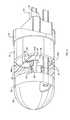
- the catheter or probe 10 described in the above applicationincludes an inner conductor 16 and a coaxial tubular outer conductor 18 .
- the distal or leading end 16 a of conductor 16is connected to the center of a conductive discoid toe plate 22 spaced in front of the outer conductor 18 which space is filled by a discoid dielectric spacer member 24 .
- a hemispherical conductive shell 26is mounted to the distal face of toe plate 22 . Together they form a conductive distal end or tip 10 a of probe 10 .
- Shell 26also defines a fluid-tight space 28 between the shell wall and the toe plate.
- the proximal or trailing end of outer conductor 18is closed by a discoid heel cap 30 connected to conductor 18 and to the proximal end 16 b of inner conductor 16 which end extends into an opening 32 at the center of heel cap 30 .
- the proximal end of center conductor 16is also connected to the distal end of an inner conductor 33 of cable 14 . Those two conductors meet in opening 32 with the cable end being anchored to heel cap 30 .
- the segment of inner conductor 16 within the outer conductor 18carries a dielectric sleeve 34 and is supported within conductor 18 by a conductive insert or carrier 36 which fits in, and extends the length of, conductor 18 , thus forming a coaxial transmission line.
- the conductor 16 and its sleeve 34extend along an axial passage 38 in the insert.
- Insert 36is in electrical contact with both outer conductor 18 and heel cap 30 .
- a sheath 52 of a dielectric materialsurrounds the outer conductor 18 of catheter 10 . However, that sheath does not extend all the way to the distal end of the conductor, but rather terminates at a selected distance therefrom. The proximal end of sheath 52 blends into cable 14 .
- a filter circuit 54 and a microwave radiometer circuit 56are mounted to the top of insert 36 .
- a coupling capacitor 58which is recessed into the spacer member 24 .
- One terminal of capacitor 58is connected electrically to conductor 16 and the other is connected by way of a lead (strip or wire) 60 to the first circuit 54 which is, in turn, connected to circuit 56 .
- the output signal from the last circuit 56 as well as certain bias and control voltagesare carried on a conductor group 64 which extends along the top of insert or carrier 36 and exits the catheter through a hole 66 in heel cap 30 .
- those conductorsjoin corresponding conductors 68 ( FIG. 2 ) which extend along cable 14 to an external control unit (not shown).
- a ground return conductor 69 from circuit 56connects to a corresponding conductor 70 in cable 14 .
- the radiometeroperates at a frequency in the microwave range.
- a conventional Dicke-type microwave radiometeris disclosed in my U.S. Pat. No. 4,557,272. Similar radiometer designs on a chip are available from Meridian Medical Systems, LLC, the assignee of this application.
- the inner conductor 16 in catheter 10comprises an RF coaxial transmission line terminated by the conductive rounded tip 10 a .
- the transmission lineis operated at the output signal frequency of a remote transmitter is (not shown).
- the transmission linewill radiate energy for heating only from the uninsulated segment of the catheter between the catheter tip 10 a and the distal end of the dielectric sheath 52 .
- that segmentconstitutes a RF heating or transmitting antenna T whose length is determined by the forward or distal extent of sheath 52 on outer conductor 18 .
- increasing the length of sheath 52will reduce the exposed length of conductor 18 , i.e. the surface that could contact tissue, and, in turn, will reduce the antenna T length.
- the outer conductor 18is at the same RF potential as conductor 16 , it can provide an RF path between the antenna T and the transmitter.
- a passive diplexer Dis integrated into catheter 10 in order to block the transmitter signals from the microwave receiving path and isolate the microwave signals from the signal path from the transmitter.
- the diplexer Dis formed by the filter circuit 54 coupled with lead 60 and capacitor 58 along with a quarter-wave ( ⁇ R /4) shorted stub S ( FIG. 1 ) constituted by the segment of catheter 10 extending from the connection of capacitor 58 to conductor 16 , to the heel cap 30 .
- This quarter wave stub Sshould be tuned to the frequency of the radiometer, thus providing a low loss path to circuit 56 .
- the diplexer Dalso includes a high pass filter in at least one of circuits 54 , 56 .
- the length of stub Sbe as short as possible.
- the present inventionaims to provide an improved, minimally invasive antenna catheter or probe for simultaneously controllably heating, and sensing the temperature of, fluid or tissue in a human or animal body.
- Another object of the inventionis provide an integrated antenna catheter including a built-in diplexer and microwave receiver which, when connected to an external control unit containing a transmitter, can simultaneously heat, and detect the temperature of, fluid or tissue adjacent to the catheter.
- a further object of the inventionis provide such a probe which is simpler and less expensive to make than prior comparable probes of this general type.
- Still another object of the inventionis to provide a probe of this type which has accurate and reliable operating parameters.
- Another objectis to provide such a probe which is very small so that it can be used in many minimally invasive applications.
- this medical probeincorporates a single, dual frequency antenna structure which can receive from a transmitter, and radiate, an electromagnetic signal of a first frequency capable of heating tissue, and pick up a microwave signal from that tissue of a second frequency indicative of tissue temperature at depth, which received signal may be routed to a receiver contained right in the probe.
- the antennahas a single center conductor and the two signals are isolated by a diplexer also integrated into the is probe which includes a shorted quarter wave stub in the signal transmitting path and a filter circuit in the signal receiving path.
- the stub in the present probecomprises a transmission line of the slab-line or suspended substrate type.
- This type of transmission linedoes not require a dielectric sleeve around the center conductor as described in the above prior application. Accordingly, this quarter wave stub is easier and less expensive to make than the prior stub. Consequently, its incorporation into the present probe minimizes the overall cost of same.
- the utilization of a slab-line or suspended substrate-type quarter wave stub in the present probefacilitates tuning the impedance of the stub. It also enables the use in the probe of a relatively large diameter center conductor without materially increasing the overall diameter of the probe. This, in turn, enables the center conductor to be formed as a tube by which a cooling or irrigation fluid may be conducted to, and dispensed from, the probe tip.
- FIG. 1is a longitudinal sectional view of the probe described in the above pending application;
- FIG. 2is a fragmentary perspective view with parts broken away thereof;
- FIG. 3is a similar view on a larger scale showing a portion of the FIG. 1 probe in greater detail;
- FIG. 4is a perspective view of a probe incorporating the present invention.
- FIG. 5is an exploded perspective view showing the components of the FIG. 4 probe in greater detail
- FIG. 6is a similar view showing certain assembled elements of the probe
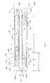
- FIG. 7is a view in axial section on a larger scale of the fully assembled probe
- FIG. 8is a sectional view on a still larger scale taken along line 8 - 8 of FIG. 7
- FIG. 9is a sectional view similar to FIG. 8 illustrating a second probe embodiment incorporating the invention.
- FIG. 10is a graphical diagram showing certain operating parameters of the FIG. 9 probe embodiment.
- FIGS. 4 and 5 of the drawingsshow the probe of this invention indicated generally at 100 .
- the former figureillustrates the probe fully assembled, while in the latter figure, the probe is in a disassembled state.
- the probecomprises an inner or center conductor 102 supported by a conductive carrier or is insert 104 .
- Carrier 104is formed from a cylindrical metal body having an axial passage 106 that receives conductor 102 .
- Upper and lower sectors of that body inboard the ends thereofare milled away to expose passage 106 and conductor 102 therein and to form upper and lower substantially parallel flats 108 a and 108 b .
- Flat 108 ais composed of coplanar rectangular areas 108 aa spaced on opposite sides of conductor 102 near the top thereof.
- carrier 104is composed of a center segment 104 a containing the flats and distal and proximal end segments 104 b and 104 c , respectively, which remain cylindrical, except that a vertical groove 107 is formed in proximal segment 104 c for reasons to be described later.
- the center conductor 102is fixed coaxially within passage 106 by means of an electrically insulating collar or bushing 109 , e.g. of PTFE, press fit into the passage 106 at the distal end segment 104 b of the carrier and by a weld 110 to the passage wall or by an electrically conductive collar or bushing (not shown) at the carrier proximal segment 104 c .
- an electrically insulating collar or bushing 109e.g. of PTFE
- Conductor 102has a distal end segment 102 a which extends beyond the distal end of carrier 104 a selected distance to be described is later and a proximal end segment 102 b which extends from the proximal end of probe 100 and connects to the center conductor of a coaxial cable 111 similar to cable 14 in FIG. 1 .
- each plate 112 a , 112 bcomprises a thin, e.g. 0.005 in., substrate 114 formed of an electrically insulating material having a high dielectric constant.
- Printed, plated or otherwise formed on the opposing or facing surfaces of substrates 114are axially centered, lengthwise conductive strips 116 , preferably 0.013-0.016 mm wide, which extend the entire lengths of substrates 114 .
- the opposite or away-facing surfaces of substrates 114are plated with conductive layers 118 , e.g. of gold. As best seen in FIG. 8 , the side edges of layers 118 wrap around the side edges of the substrates.
- the plate 112 aWhen the probe is being assembled, the plate 112 a is seated on the upper flat 108 a of carrier 104 and the lower plate 112 b is likewise seated on the lower flat 108 b as shown in FIGS. 7 and 8 so that the center conductor 102 is contacted from above and below by the conductive strips 116 of the upper and lower plates and the layer 118 side edges of those plates contact carrier segment 104 a .
- a suitable conductive epoxy or cementshould be applied between those contacting surfaces to secure the plates in place.
- the platesfunctions also as a support surface for one or more monolithic integrated circuit chips (MMICs), e.g. chips 122 and 124 .
- MMICsmonolithic integrated circuit chips
- the chip(s)may include a coupling capacitor connected by a lead 125 ( FIG. 7 ) to center conductor 102 and the usual components of a radiometer such as a Dicke switch, a noise source to provide a reference temperature, amplifier stages, a band pass filter to establish the radiometer bandwidth, additional gain stages if needed, a detector and buffer amplifier. Due to the very small profile of the present probe 100 , the above circuit components are actually organized in a string of four chips.
- the chip(s)may be secured to the metal layer 118 of plate 112 a by a suitable conductive adhesive so that that layer which, as described above, is grounded to the insert 104 may function as a ground plane for those chips.
- the platesalso conduct heat away from the chips to conductor 102 and carrier 104 .
- various leads 125 aconnect the chips to each other and other leads 125 b extend through carrier slot 107 and connect the last chip 124 in the string, i.e. the radiometer output, to corresponding conductors of the cable 111 leading to a remote unit similar to the one described in the above application.
- the output of the radiometeris actually a video output adapted to be coupled to a remote interface box.
- a tubular outer conductor 126may be slid onto carrier 104 from an end thereof so that it snugly engages around the carrier with its proximal and distal ends coinciding with the corresponding ends of the carrier as best seen in FIG. 7 .
- the conductor 126may be fixed in place by a conductive epoxy or cement applied around the carrier segments 104 b and 104 c.
- Probe 100also includes an annular dielectric spacer 132 , e.g. of PTFE, which is centered on the distal end of carrier 104 and surrounds the conductor segment 102 a .
- the spacermay have a slit 132 a enabling it to be engaged around that conductor segment from the side thereof.
- the spacer 132may be held in place is by a conductive collar 136 which encircles the spacer and is long enough to slidably engage over a distal end segment of outer conductor 126 .
- the collarmay be press fit around that conductor and carrier segment 104 b to hold it in place and to electrically connect all those elements.
- the distal end of the probe 100is closed off by a conductive tip 142 which, in axial section, is T shaped. That is, the tip 142 has a discoid head 142 a which constitutes the distal end of the probe and an axially extending tubular neck 142 b .
- the conductor segment 102 ais long enough to extend beyond the distal end of the spacer 132 into the axial passage in neck 104 b .
- the tipmay be secured in place by conductive adhesive applied around the distal end of conductor segment 102 a and at the distal end or edge of collar 136 . When the tip is in place, the conductor segment 102 a and tip 104 form a receiving antenna R ( FIG. 7 ) similar to the one described in connection with FIG. 1 .
- the final component of probe 100is a dielectric sheath 144 which may be engaged over the rear end of outer conductor 126 and slid forwardly until its distal end 144 a is spaced a selected distance behind the distal end of tip 142 .
- the conductors 102 and 126 of probe 100comprise a RF transmission line terminated by the tip 104 .
- the transmission lineradiates energy for heating tissue only from the uninsulated segment of the probe between tip 104 and the distal end 144 a of the sheath 144 . That segment thus constitutes a heating or transmitting antenna T ( FIG. 7 ), the antennas R and T forming a single dual frequency antenna structure.
- the proximal ends of the center conductor segment 102 b , outer conductor 126 and sheath 144may be connected, respectively, to the inner and outer conductors and outer sheath of cable 111 that leads to an external control unit as described in the above application.
- those elementsmay be extensions of the corresponding components of cable 111 .
- that cable 111connects the center conductor 102 to the output of a transmitter which transmits a RF heating signal at a selected heating frequency, e.g. 500 GHz, to antenna T.
- that cable 111may include a probe steering wire 145 whose leading end 145 a may be secured to the wall of a passage 146 in carrier segment 104 c.
- a helical through slot 147is provided in collar 136 as shown in FIGS. 4 , 5 and 7 .
- the collar material left between the slotturns essentially forms a helical wire 148 that bridges the spacer 132 .
- Wire 148is found to improve the RF heating pattern of transmitting antenna T without materially degrading the microwave antenna pattern of receiving antenna R.
- the inner or center conductor 102may be a solid wire as shown in FIG. 6 . More preferably, it is formed as a tube as seen in FIGS. 7 and 8 . This enables the conductor 102 to carry an irrigation fluid or coolant to the interior of probe tip 142 for distribution therefrom through radial passages 150 in tip head 142 a that communicate with the distal end of the axial passage in tip neck 142 b.
- plates 112 a , 112 b and the conductor 102 segment together with carrier 104form a quarter wave
- the quarter wave stub Stuned to the center frequency of the radiometer circuit 124 along with components in the chips 122 , 124 form a low pass filter in the signal transmitting path to the antenna T, while other components of the chips comprise a high pass or band pass filter in the signal receiving path from the antenna to the radiometer.
- the combinationconstitutes a passive diplexer D which prevents the lower frequency transmitter signals on the signal transmitting path from antenna T from reaching the radiometer, while isolating the path to the transmitter from the higher frequency signals on the signal receiving path from the antenna.
- the impedance of the quarter wave stub Sdepends upon the K value and thickness t of the substrates 114 of the two plates 112 a , 112 b and the spacing of the center conductor 102 from the walls 106 a , 106 a of passage 106 in the carrier center segment 104 a . Since the center conductor 102 is not surrounded by a ceramic sleeve, those walls can be moved closer to the center conductor, enabling accurate tuning of the suspended substrate transmission line impedance while minimizing the overall diameter of the probe 100 . As noted above, the length of the stub S is also minimized by making substrate 114 of a dielectric material which has an especially high K value.
- the components of the probehave the following dimensions:
- the overall length and diameter of the probe 100can still be kept to a minimum which is an important requirement for probes used in minimally invasive applications.
- each platecomprises a dielectric substrate 206 , a conductive layer 208 grounded to carrier segment 104 a and a broad conductive strip 210 facing the center conductor 202 .
- each stripinstead of being printed on the substrate, is a conductive epoxy film applied to the substrate.
- the forces exerted by conductor 206 on the ceramic substrateare distributed over a relatively large area so as to minimize the chances of cracking the thin ceramic substrates 206 of plate 204 a , 204 b .
- such large-area contact between the plates and conductor 202widens the thermal path from the chip(s) 122 , 124 to conductor 202 and any fluid therein, thus optimizing the cooling of the chip(s).
- the thickness of the epoxy strips 208may be carefully controlled to adjust the impedance of the transmission line.
- FIG. 10is a graph showing how that impedance varies with the thickness of the epoxy film.
- the above described probescan transmit and receive signals simultaneously to both heat tissue or fluid and detect the temperature of that tissue or fluid in real time, thus enabling the efficient performance of various medical procedures.
- the fact that the diplexer D and radiometer circuit 124 may be incorporated right into the probes 100 and 200enables the probes to provide very precise and noise-free temperature measurements in a minimum amount of time.
Landscapes
- Health & Medical Sciences (AREA)
- Life Sciences & Earth Sciences (AREA)
- Animal Behavior & Ethology (AREA)
- Veterinary Medicine (AREA)
- Public Health (AREA)
- Engineering & Computer Science (AREA)
- Biomedical Technology (AREA)
- General Health & Medical Sciences (AREA)
- Pathology (AREA)
- Molecular Biology (AREA)
- Surgery (AREA)
- Medical Informatics (AREA)
- Heart & Thoracic Surgery (AREA)
- Physics & Mathematics (AREA)
- Biophysics (AREA)
- Nuclear Medicine, Radiotherapy & Molecular Imaging (AREA)
- Radiology & Medical Imaging (AREA)
- Radiation Pyrometers (AREA)
- Measuring And Recording Apparatus For Diagnosis (AREA)
Abstract
Description
stub S which should be tuned to the frequency of the
| Part | Dimension (in.) |
| 0.020 OD; 0.016 ID (if present) | |
| Substrate 114 (K = 9.8) | 0.065 wide; t = 0.005 |
| Strips 116 | W = 0.015 |
| Air gap between 102 and each 106a | 0.015 |
Claims (20)
Priority Applications (1)
| Application Number | Priority Date | Filing Date | Title |
|---|---|---|---|
| US12/626,004US8515554B2 (en) | 2006-06-26 | 2009-11-25 | Radiometric heating/sensing probe |
Applications Claiming Priority (2)
| Application Number | Priority Date | Filing Date | Title |
|---|---|---|---|
| US11/474,883US7769469B2 (en) | 2006-06-26 | 2006-06-26 | Integrated heating/sensing catheter apparatus for minimally invasive applications |
| US12/626,004US8515554B2 (en) | 2006-06-26 | 2009-11-25 | Radiometric heating/sensing probe |
Related Parent Applications (1)
| Application Number | Title | Priority Date | Filing Date |
|---|---|---|---|
| US11/474,883Continuation-In-PartUS7769469B2 (en) | 2006-06-26 | 2006-06-26 | Integrated heating/sensing catheter apparatus for minimally invasive applications |
Publications (2)
| Publication Number | Publication Date |
|---|---|
| US20100076424A1 US20100076424A1 (en) | 2010-03-25 |
| US8515554B2true US8515554B2 (en) | 2013-08-20 |
Family
ID=42038409
Family Applications (1)
| Application Number | Title | Priority Date | Filing Date |
|---|---|---|---|
| US12/626,004Expired - Fee RelatedUS8515554B2 (en) | 2006-06-26 | 2009-11-25 | Radiometric heating/sensing probe |
Country Status (1)
| Country | Link |
|---|---|
| US (1) | US8515554B2 (en) |
Cited By (29)
| Publication number | Priority date | Publication date | Assignee | Title |
|---|---|---|---|---|
| US20100286686A1 (en)* | 2007-09-25 | 2010-11-11 | Christopher Paul Hancock | Surgical resection apparatus |
| US8926605B2 (en) | 2012-02-07 | 2015-01-06 | Advanced Cardiac Therapeutics, Inc. | Systems and methods for radiometrically measuring temperature during tissue ablation |
| US8954161B2 (en) | 2012-06-01 | 2015-02-10 | Advanced Cardiac Therapeutics, Inc. | Systems and methods for radiometrically measuring temperature and detecting tissue contact prior to and during tissue ablation |
| US8961506B2 (en) | 2012-03-12 | 2015-02-24 | Advanced Cardiac Therapeutics, Inc. | Methods of automatically regulating operation of ablation members based on determined temperatures |
| US9277961B2 (en) | 2009-06-12 | 2016-03-08 | Advanced Cardiac Therapeutics, Inc. | Systems and methods of radiometrically determining a hot-spot temperature of tissue being treated |
| US9510905B2 (en) | 2014-11-19 | 2016-12-06 | Advanced Cardiac Therapeutics, Inc. | Systems and methods for high-resolution mapping of tissue |
| US9517103B2 (en) | 2014-11-19 | 2016-12-13 | Advanced Cardiac Therapeutics, Inc. | Medical instruments with multiple temperature sensors |
| US9566115B2 (en) | 2009-07-28 | 2017-02-14 | Neuwave Medical, Inc. | Energy delivery systems and uses thereof |
| US9610122B2 (en) | 2013-03-29 | 2017-04-04 | Covidien Lp | Step-down coaxial microwave ablation applicators and methods for manufacturing same |
| USRE46362E1 (en) | 2009-11-16 | 2017-04-11 | Covidien Lp | Twin sealing chamber hub |
| US9636164B2 (en) | 2015-03-25 | 2017-05-02 | Advanced Cardiac Therapeutics, Inc. | Contact sensing systems and methods |
| US9861440B2 (en) | 2010-05-03 | 2018-01-09 | Neuwave Medical, Inc. | Energy delivery systems and uses thereof |
| US9993178B2 (en) | 2016-03-15 | 2018-06-12 | Epix Therapeutics, Inc. | Methods of determining catheter orientation |
| US10166062B2 (en) | 2014-11-19 | 2019-01-01 | Epix Therapeutics, Inc. | High-resolution mapping of tissue with pacing |
| US10363092B2 (en) | 2006-03-24 | 2019-07-30 | Neuwave Medical, Inc. | Transmission line with heat transfer ability |
| US10376314B2 (en) | 2006-07-14 | 2019-08-13 | Neuwave Medical, Inc. | Energy delivery systems and uses thereof |
| US10376309B2 (en) | 2016-08-02 | 2019-08-13 | Covidien Lp | Ablation cable assemblies and a method of manufacturing the same |
| US10531917B2 (en) | 2016-04-15 | 2020-01-14 | Neuwave Medical, Inc. | Systems and methods for energy delivery |
| US10624697B2 (en) | 2014-08-26 | 2020-04-21 | Covidien Lp | Microwave ablation system |
| US10667860B2 (en) | 2011-12-21 | 2020-06-02 | Neuwave Medical, Inc. | Energy delivery systems and uses thereof |
| US10813691B2 (en) | 2014-10-01 | 2020-10-27 | Covidien Lp | Miniaturized microwave ablation assembly |
| US10888373B2 (en) | 2017-04-27 | 2021-01-12 | Epix Therapeutics, Inc. | Contact assessment between an ablation catheter and tissue |
| US10952792B2 (en) | 2015-10-26 | 2021-03-23 | Neuwave Medical, Inc. | Energy delivery systems and uses thereof |
| US11065053B2 (en) | 2016-08-02 | 2021-07-20 | Covidien Lp | Ablation cable assemblies and a method of manufacturing the same |
| US11197715B2 (en) | 2016-08-02 | 2021-12-14 | Covidien Lp | Ablation cable assemblies and a method of manufacturing the same |
| US11389235B2 (en) | 2006-07-14 | 2022-07-19 | Neuwave Medical, Inc. | Energy delivery systems and uses thereof |
| US11672596B2 (en) | 2018-02-26 | 2023-06-13 | Neuwave Medical, Inc. | Energy delivery devices with flexible and adjustable tips |
| US11678934B2 (en) | 2012-08-07 | 2023-06-20 | Covidien Lp | Microwave ablation system |
| US11832879B2 (en) | 2019-03-08 | 2023-12-05 | Neuwave Medical, Inc. | Systems and methods for energy delivery |
Families Citing this family (18)
| Publication number | Priority date | Publication date | Assignee | Title |
|---|---|---|---|---|
| US7137980B2 (en) | 1998-10-23 | 2006-11-21 | Sherwood Services Ag | Method and system for controlling output of RF medical generator |
| AU2004235739B2 (en) | 2003-05-01 | 2010-06-17 | Covidien Ag | Method and system for programming and controlling an electrosurgical generator system |
| WO2005050151A1 (en) | 2003-10-23 | 2005-06-02 | Sherwood Services Ag | Thermocouple measurement circuit |
| US7396336B2 (en) | 2003-10-30 | 2008-07-08 | Sherwood Services Ag | Switched resonant ultrasonic power amplifier system |
| US7947039B2 (en) | 2005-12-12 | 2011-05-24 | Covidien Ag | Laparoscopic apparatus for performing electrosurgical procedures |
| CA2574934C (en) | 2006-01-24 | 2015-12-29 | Sherwood Services Ag | System and method for closed loop monitoring of monopolar electrosurgical apparatus |
| US8262652B2 (en) | 2009-01-12 | 2012-09-11 | Tyco Healthcare Group Lp | Imaginary impedance process monitoring and intelligent shut-off |
| US20110208179A1 (en)* | 2010-02-25 | 2011-08-25 | Tyco Healthcare Group Lp | Patient Isolation in a Microwave-Radio Frequency Generator |
| US9028482B2 (en) | 2011-07-19 | 2015-05-12 | Covidien Lp | Microwave and RF ablation system and related method for dynamic impedance matching |
| US8968297B2 (en) | 2011-07-19 | 2015-03-03 | Covidien Lp | Microwave and RF ablation system and related method for dynamic impedance matching |
| US9192422B2 (en) | 2011-07-19 | 2015-11-24 | Covidien Lp | System and method of matching impedances of an electrosurgical generator and/or a microwave generator |
| US20130281851A1 (en)* | 2012-04-19 | 2013-10-24 | Kenneth L. Carr | Heating/sensing catheter apparatus for minimally invasive applications |
| CN104507408B (en) | 2012-06-22 | 2017-06-20 | 柯惠有限合伙公司 | For the microwave thermometric of microwave ablation system |
| US9872719B2 (en) | 2013-07-24 | 2018-01-23 | Covidien Lp | Systems and methods for generating electrosurgical energy using a multistage power converter |
| US9655670B2 (en) | 2013-07-29 | 2017-05-23 | Covidien Lp | Systems and methods for measuring tissue impedance through an electrosurgical cable |
| DE202014102548U1 (en) | 2014-05-30 | 2014-08-01 | Advanced Cardiac Therapeutics, Inc. | Systems for radiometrically measuring a temperature and detecting tissue contact before and during a tissue ablation |
| US10813692B2 (en) | 2016-02-29 | 2020-10-27 | Covidien Lp | 90-degree interlocking geometry for introducer for facilitating deployment of microwave radiating catheter |
| US12226143B2 (en) | 2020-06-22 | 2025-02-18 | Covidien Lp | Universal surgical footswitch toggling |
Citations (16)
| Publication number | Priority date | Publication date | Assignee | Title |
|---|---|---|---|---|
| US3355679A (en)* | 1964-03-20 | 1967-11-28 | Ferrotec Inc | Impedance matched stripline ferrite y circulator having increased ground plane spacing at the junction of the center conductors |
| US4557272A (en) | 1980-03-31 | 1985-12-10 | Microwave Associates, Inc. | Microwave endoscope detection and treatment system |
| US4583556A (en) | 1982-12-13 | 1986-04-22 | M/A-Com, Inc. | Microwave applicator/receiver apparatus |
| JPH05253239A (en) | 1992-03-10 | 1993-10-05 | Olympus Optical Co Ltd | Heating unit |
| US5364336A (en) | 1990-12-17 | 1994-11-15 | Microwave Medical Systems, Inc. | Therapeutic probe for radiating microwave and ionizing radiation |
| US5531662A (en) | 1990-12-17 | 1996-07-02 | Microwave Medical Systems, Inc. | Dual mode microwave/ionizing probe |
| US5683382A (en) | 1995-05-15 | 1997-11-04 | Arrow International Investment Corp. | Microwave antenna catheter |
| US5688050A (en) | 1995-04-03 | 1997-11-18 | Mmtc, Inc. | Temperature-measuring microwave radiometer apparatus |
| US5974343A (en) | 1996-01-12 | 1999-10-26 | Bruker Sa | Probe, particulary a urethral probe, for heating of tissues by microwave and for the measurement of temperature by radiometry |
| US6424869B1 (en) | 1995-09-06 | 2002-07-23 | Meridian Medical Systems, Llc | Dual mode transurethral microwave warming apparatus |
| US6496738B2 (en) | 1995-09-06 | 2002-12-17 | Kenneth L. Carr | Dual frequency microwave heating apparatus |
| US20040243004A1 (en) | 2003-06-02 | 2004-12-02 | Carr Kenneth L. | Method and apparatus for detecting and treating vulnerable plaques |
| US20040267115A1 (en)* | 2003-06-25 | 2004-12-30 | Carr Kenneth L. | Method and apparatus for measuring intravascular blood flow |
| JP2005040307A (en) | 2003-07-28 | 2005-02-17 | Murata Mfg Co Ltd | Coaxial probe |
| US20070083244A1 (en)* | 2005-10-06 | 2007-04-12 | Greatbatch-Sierra, Inc. | Process for tuning an emi filter to reduce the amount of heat generated in implanted lead wires during medical procedures such as magnetic resonance imaging |
| US20070299488A1 (en) | 2006-06-26 | 2007-12-27 | Carr Kenneth L | Integrated heating/sensing catheter apparatus for minimally invasive applications |
- 2009
- 2009-11-25USUS12/626,004patent/US8515554B2/ennot_activeExpired - Fee Related
Patent Citations (21)
| Publication number | Priority date | Publication date | Assignee | Title |
|---|---|---|---|---|
| US3355679A (en)* | 1964-03-20 | 1967-11-28 | Ferrotec Inc | Impedance matched stripline ferrite y circulator having increased ground plane spacing at the junction of the center conductors |
| US4557272A (en) | 1980-03-31 | 1985-12-10 | Microwave Associates, Inc. | Microwave endoscope detection and treatment system |
| US4583556A (en) | 1982-12-13 | 1986-04-22 | M/A-Com, Inc. | Microwave applicator/receiver apparatus |
| US5364336A (en) | 1990-12-17 | 1994-11-15 | Microwave Medical Systems, Inc. | Therapeutic probe for radiating microwave and ionizing radiation |
| US5531662A (en) | 1990-12-17 | 1996-07-02 | Microwave Medical Systems, Inc. | Dual mode microwave/ionizing probe |
| JPH05253239A (en) | 1992-03-10 | 1993-10-05 | Olympus Optical Co Ltd | Heating unit |
| US5688050A (en) | 1995-04-03 | 1997-11-18 | Mmtc, Inc. | Temperature-measuring microwave radiometer apparatus |
| US5683382A (en) | 1995-05-15 | 1997-11-04 | Arrow International Investment Corp. | Microwave antenna catheter |
| US6496738B2 (en) | 1995-09-06 | 2002-12-17 | Kenneth L. Carr | Dual frequency microwave heating apparatus |
| US6424869B1 (en) | 1995-09-06 | 2002-07-23 | Meridian Medical Systems, Llc | Dual mode transurethral microwave warming apparatus |
| US5974343A (en) | 1996-01-12 | 1999-10-26 | Bruker Sa | Probe, particulary a urethral probe, for heating of tissues by microwave and for the measurement of temperature by radiometry |
| US20040243004A1 (en) | 2003-06-02 | 2004-12-02 | Carr Kenneth L. | Method and apparatus for detecting and treating vulnerable plaques |
| US20040249272A1 (en) | 2003-06-02 | 2004-12-09 | Carr Kenneth L. | Microwave detection apparatus |
| US6932776B2 (en) | 2003-06-02 | 2005-08-23 | Meridian Medicalssystems, Llc | Method and apparatus for detecting and treating vulnerable plaques |
| US20050203388A1 (en)* | 2003-06-02 | 2005-09-15 | Carr Kenneth L. | Method and apparatus for detecting and treating vulnerable plaques |
| US7933660B2 (en)* | 2003-06-02 | 2011-04-26 | Meridian Medical Systems | Apparatus for detecting and treating vulnerable plaques |
| US20040267115A1 (en)* | 2003-06-25 | 2004-12-30 | Carr Kenneth L. | Method and apparatus for measuring intravascular blood flow |
| JP2005040307A (en) | 2003-07-28 | 2005-02-17 | Murata Mfg Co Ltd | Coaxial probe |
| US20070083244A1 (en)* | 2005-10-06 | 2007-04-12 | Greatbatch-Sierra, Inc. | Process for tuning an emi filter to reduce the amount of heat generated in implanted lead wires during medical procedures such as magnetic resonance imaging |
| US20070299488A1 (en) | 2006-06-26 | 2007-12-27 | Carr Kenneth L | Integrated heating/sensing catheter apparatus for minimally invasive applications |
| US7769469B2 (en)* | 2006-06-26 | 2010-08-03 | Meridian Medical Systems, Llc | Integrated heating/sensing catheter apparatus for minimally invasive applications |
Cited By (77)
| Publication number | Priority date | Publication date | Assignee | Title |
|---|---|---|---|---|
| US11944376B2 (en) | 2006-03-24 | 2024-04-02 | Neuwave Medical, Inc. | Transmission line with heat transfer ability |
| US10363092B2 (en) | 2006-03-24 | 2019-07-30 | Neuwave Medical, Inc. | Transmission line with heat transfer ability |
| US11389235B2 (en) | 2006-07-14 | 2022-07-19 | Neuwave Medical, Inc. | Energy delivery systems and uses thereof |
| US10376314B2 (en) | 2006-07-14 | 2019-08-13 | Neuwave Medical, Inc. | Energy delivery systems and uses thereof |
| US11576723B2 (en) | 2006-07-14 | 2023-02-14 | Neuwave Medical, Inc. | Energy delivery systems and uses thereof |
| US11576722B2 (en) | 2006-07-14 | 2023-02-14 | Neuwave Medical, Inc. | Energy delivery systems and uses thereof |
| US11596474B2 (en) | 2006-07-14 | 2023-03-07 | Neuwave Medical, Inc. | Energy delivery systems and uses thereof |
| US8795267B2 (en)* | 2007-09-25 | 2014-08-05 | Creo Medical Limited | Surgical resection apparatus |
| US20140330265A1 (en)* | 2007-09-25 | 2014-11-06 | Creo Medical Limited | Surgical resection apparatus |
| US11065054B2 (en) | 2007-09-25 | 2021-07-20 | Creo Medical Limited | Surgical resection apparatus |
| US20100286686A1 (en)* | 2007-09-25 | 2010-11-11 | Christopher Paul Hancock | Surgical resection apparatus |
| US9707037B2 (en)* | 2007-09-25 | 2017-07-18 | Creo Medical Limited | Surgical resection apparatus |
| US9277961B2 (en) | 2009-06-12 | 2016-03-08 | Advanced Cardiac Therapeutics, Inc. | Systems and methods of radiometrically determining a hot-spot temperature of tissue being treated |
| US9877783B2 (en) | 2009-07-28 | 2018-01-30 | Neuwave Medical, Inc. | Energy delivery systems and uses thereof |
| US9566115B2 (en) | 2009-07-28 | 2017-02-14 | Neuwave Medical, Inc. | Energy delivery systems and uses thereof |
| US10357312B2 (en) | 2009-07-28 | 2019-07-23 | Neuwave Medical, Inc. | Energy delivery systems and uses thereof |
| US11013557B2 (en) | 2009-07-28 | 2021-05-25 | Neuwave Medical, Inc. | Energy delivery systems and uses thereof |
| USRE46362E1 (en) | 2009-11-16 | 2017-04-11 | Covidien Lp | Twin sealing chamber hub |
| US12376903B2 (en) | 2010-05-03 | 2025-08-05 | Neuwave Medical, Inc. | Energy delivery systems and uses thereof |
| US9861440B2 (en) | 2010-05-03 | 2018-01-09 | Neuwave Medical, Inc. | Energy delivery systems and uses thereof |
| US9872729B2 (en) | 2010-05-03 | 2018-01-23 | Neuwave Medical, Inc. | Energy delivery systems and uses thereof |
| US10524862B2 (en) | 2010-05-03 | 2020-01-07 | Neuwave Medical, Inc. | Energy delivery systems and uses thereof |
| US10603106B2 (en) | 2010-05-03 | 2020-03-31 | Neuwave Medical, Inc. | Energy delivery systems and uses thereof |
| US11490960B2 (en) | 2010-05-03 | 2022-11-08 | Neuwave Medical, Inc. | Energy delivery systems and uses thereof |
| US10667860B2 (en) | 2011-12-21 | 2020-06-02 | Neuwave Medical, Inc. | Energy delivery systems and uses thereof |
| US11638607B2 (en) | 2011-12-21 | 2023-05-02 | Neuwave Medical, Inc. | Energy delivery systems and uses thereof |
| US8932284B2 (en) | 2012-02-07 | 2015-01-13 | Advanced Cardiac Therapeutics, Inc. | Methods of determining tissue temperatures in energy delivery procedures |
| US8926605B2 (en) | 2012-02-07 | 2015-01-06 | Advanced Cardiac Therapeutics, Inc. | Systems and methods for radiometrically measuring temperature during tissue ablation |
| US9226791B2 (en) | 2012-03-12 | 2016-01-05 | Advanced Cardiac Therapeutics, Inc. | Systems for temperature-controlled ablation using radiometric feedback |
| US8961506B2 (en) | 2012-03-12 | 2015-02-24 | Advanced Cardiac Therapeutics, Inc. | Methods of automatically regulating operation of ablation members based on determined temperatures |
| US9014814B2 (en) | 2012-06-01 | 2015-04-21 | Advanced Cardiac Therapeutics, Inc. | Methods of determining tissue contact based on radiometric signals |
| US8954161B2 (en) | 2012-06-01 | 2015-02-10 | Advanced Cardiac Therapeutics, Inc. | Systems and methods for radiometrically measuring temperature and detecting tissue contact prior to and during tissue ablation |
| US11678934B2 (en) | 2012-08-07 | 2023-06-20 | Covidien Lp | Microwave ablation system |
| US10383688B2 (en) | 2013-03-29 | 2019-08-20 | Covidien Lp | Step-down coaxial microwave ablation applicators and methods for manufacturing same |
| US11382692B2 (en) | 2013-03-29 | 2022-07-12 | Covidien Lp | Step-down coaxial microwave ablation applicators and methods for manufacturing same |
| US9987087B2 (en) | 2013-03-29 | 2018-06-05 | Covidien Lp | Step-down coaxial microwave ablation applicators and methods for manufacturing same |
| US12318135B2 (en) | 2013-03-29 | 2025-06-03 | Covidien Lp | Step-down coaxial microwave ablation applicators and methods for manufacturing same |
| US9610122B2 (en) | 2013-03-29 | 2017-04-04 | Covidien Lp | Step-down coaxial microwave ablation applicators and methods for manufacturing same |
| US10624697B2 (en) | 2014-08-26 | 2020-04-21 | Covidien Lp | Microwave ablation system |
| US11974805B2 (en) | 2014-08-26 | 2024-05-07 | Covidien Lp | Microwave ablation system |
| US10813691B2 (en) | 2014-10-01 | 2020-10-27 | Covidien Lp | Miniaturized microwave ablation assembly |
| US11839426B2 (en) | 2014-10-01 | 2023-12-12 | Covidien Lp | Miniaturized microwave ablation assembly |
| US11135009B2 (en) | 2014-11-19 | 2021-10-05 | Epix Therapeutics, Inc. | Electrode assembly with thermal shunt member |
| US9522036B2 (en) | 2014-11-19 | 2016-12-20 | Advanced Cardiac Therapeutics, Inc. | Ablation devices, systems and methods of using a high-resolution electrode assembly |
| US10166062B2 (en) | 2014-11-19 | 2019-01-01 | Epix Therapeutics, Inc. | High-resolution mapping of tissue with pacing |
| US9522037B2 (en) | 2014-11-19 | 2016-12-20 | Advanced Cardiac Therapeutics, Inc. | Treatment adjustment based on temperatures from multiple temperature sensors |
| US10499983B2 (en) | 2014-11-19 | 2019-12-10 | Epix Therapeutics, Inc. | Ablation systems and methods using heat shunt networks |
| US10413212B2 (en) | 2014-11-19 | 2019-09-17 | Epix Therapeutics, Inc. | Methods and systems for enhanced mapping of tissue |
| US9510905B2 (en) | 2014-11-19 | 2016-12-06 | Advanced Cardiac Therapeutics, Inc. | Systems and methods for high-resolution mapping of tissue |
| US11534227B2 (en) | 2014-11-19 | 2022-12-27 | Epix Therapeutics, Inc. | High-resolution mapping of tissue with pacing |
| US11701171B2 (en) | 2014-11-19 | 2023-07-18 | Epix Therapeutics, Inc. | Methods of removing heat from an electrode using thermal shunting |
| US9517103B2 (en) | 2014-11-19 | 2016-12-13 | Advanced Cardiac Therapeutics, Inc. | Medical instruments with multiple temperature sensors |
| US10383686B2 (en) | 2014-11-19 | 2019-08-20 | Epix Therapeutics, Inc. | Ablation systems with multiple temperature sensors |
| US10660701B2 (en) | 2014-11-19 | 2020-05-26 | Epix Therapeutics, Inc. | Methods of removing heat from an electrode using thermal shunting |
| US11642167B2 (en) | 2014-11-19 | 2023-05-09 | Epix Therapeutics, Inc. | Electrode assembly with thermal shunt member |
| US9592092B2 (en) | 2014-11-19 | 2017-03-14 | Advanced Cardiac Therapeutics, Inc. | Orientation determination based on temperature measurements |
| US10231779B2 (en) | 2014-11-19 | 2019-03-19 | Epix Therapeutics, Inc. | Ablation catheter with high-resolution electrode assembly |
| US9636164B2 (en) | 2015-03-25 | 2017-05-02 | Advanced Cardiac Therapeutics, Inc. | Contact sensing systems and methods |
| US11576714B2 (en) | 2015-03-25 | 2023-02-14 | Epix Therapeutics, Inc. | Contact sensing systems and methods |
| US10675081B2 (en) | 2015-03-25 | 2020-06-09 | Epix Therapeutics, Inc. | Contact sensing systems and methods |
| US11678935B2 (en) | 2015-10-26 | 2023-06-20 | Neuwave Medical, Inc. | Energy delivery systems and uses thereof |
| US10952792B2 (en) | 2015-10-26 | 2021-03-23 | Neuwave Medical, Inc. | Energy delivery systems and uses thereof |
| US11179197B2 (en) | 2016-03-15 | 2021-11-23 | Epix Therapeutics, Inc. | Methods of determining catheter orientation |
| US12121291B2 (en) | 2016-03-15 | 2024-10-22 | Epix Therapeutics, Inc. | Methods of determining catheter orientation |
| US9993178B2 (en) | 2016-03-15 | 2018-06-12 | Epix Therapeutics, Inc. | Methods of determining catheter orientation |
| US11389230B2 (en) | 2016-03-15 | 2022-07-19 | Epix Therapeutics, Inc. | Systems for determining catheter orientation |
| US11395699B2 (en) | 2016-04-15 | 2022-07-26 | Neuwave Medical, Inc. | Systems and methods for energy delivery |
| US10531917B2 (en) | 2016-04-15 | 2020-01-14 | Neuwave Medical, Inc. | Systems and methods for energy delivery |
| US11197715B2 (en) | 2016-08-02 | 2021-12-14 | Covidien Lp | Ablation cable assemblies and a method of manufacturing the same |
| US11065053B2 (en) | 2016-08-02 | 2021-07-20 | Covidien Lp | Ablation cable assemblies and a method of manufacturing the same |
| US10376309B2 (en) | 2016-08-02 | 2019-08-13 | Covidien Lp | Ablation cable assemblies and a method of manufacturing the same |
| US10888373B2 (en) | 2017-04-27 | 2021-01-12 | Epix Therapeutics, Inc. | Contact assessment between an ablation catheter and tissue |
| US10893903B2 (en) | 2017-04-27 | 2021-01-19 | Epix Therapeutics, Inc. | Medical instruments having contact assessment features |
| US11617618B2 (en) | 2017-04-27 | 2023-04-04 | Epix Therapeutics, Inc. | Contact assessment between an ablation catheter and tissue |
| US11672596B2 (en) | 2018-02-26 | 2023-06-13 | Neuwave Medical, Inc. | Energy delivery devices with flexible and adjustable tips |
| US12171490B2 (en) | 2018-02-26 | 2024-12-24 | Neuwave Medical, Inc. | Energy delivery devices with flexible and adjustable tips |
| US11832879B2 (en) | 2019-03-08 | 2023-12-05 | Neuwave Medical, Inc. | Systems and methods for energy delivery |
Also Published As
| Publication number | Publication date |
|---|---|
| US20100076424A1 (en) | 2010-03-25 |
Similar Documents
| Publication | Publication Date | Title |
|---|---|---|
| US8515554B2 (en) | Radiometric heating/sensing probe | |
| EP2051617B1 (en) | Integrated heating/sensing catheter apparatus for minimally invasive applications | |
| US7113832B2 (en) | Interstitial microwave antenna with miniaturized choke hyperthermia in medicine and surgery | |
| US20070219548A1 (en) | Microwave apparatus for controlled tissue ablation | |
| US10987001B2 (en) | Heating/sensing catheter apparatus for minimally invasive applications | |
| US4700716A (en) | Collinear antenna array applicator | |
| US7393352B2 (en) | Electrode arrangement for use in a medical instrument | |
| US5057106A (en) | Microwave balloon angioplasty | |
| EP2158868B1 (en) | Dual-band dipole microwave ablation antenna | |
| US6471696B1 (en) | Microwave ablation instrument with a directional radiation pattern | |
| JP4618241B2 (en) | Coaxial probe device | |
| US6233490B1 (en) | Microwave antennas for medical hyperthermia, thermotherapy and diagnosis | |
| US6181970B1 (en) | Microwave devices for medical hyperthermia, thermotherapy and diagnosis | |
| AU2002234814A1 (en) | Interstitial microwave antenna with miniaturized choke for hyperthermia and surgery | |
| US20060189973A1 (en) | Segmented catheter for tissue ablation | |
| US20050203388A1 (en) | Method and apparatus for detecting and treating vulnerable plaques | |
| WO2012015539A2 (en) | Handheld medical microwave radiometer | |
| RU2769299C1 (en) | Electrosurgical instrument | |
| US11090113B2 (en) | Microwave ablation antenna assemblies | |
| WO2020006661A1 (en) | Microwave ablation devices | |
| EP3796859B1 (en) | Electrosurgical ablation instrument | |
| EP3958776B1 (en) | Microwave ablation device and system with impedance mismatch | |
| RU2777551C2 (en) | Electrosurgical instrument for ablation | |
| CA1291221C (en) | Method and apparatus for hyperthermia treatment | |
| WO1998022179A2 (en) | Ultrasonically marked catheter for electrotherapy and system for use of the same |
Legal Events
| Date | Code | Title | Description |
|---|---|---|---|
| AS | Assignment | Owner name:MERIDAN MEDICAL SYSTEMS, LLC,MAINE Free format text:ASSIGNMENT OF ASSIGNORS INTEREST;ASSIGNOR:CARR, KENNETH L.;REEL/FRAME:023571/0260 Effective date:20091125 Owner name:MERIDAN MEDICAL SYSTEMS, LLC, MAINE Free format text:ASSIGNMENT OF ASSIGNORS INTEREST;ASSIGNOR:CARR, KENNETH L.;REEL/FRAME:023571/0260 Effective date:20091125 | |
| AS | Assignment | Owner name:NBGI TECHNOLOGY FUND II LP, UNITED KINGDOM Free format text:SECURITY AGREEMENT;ASSIGNOR:ADVANCED CARDIAC THERAPEUTICS, INC.;REEL/FRAME:026945/0082 Effective date:20110829 | |
| STCF | Information on status: patent grant | Free format text:PATENTED CASE | |
| CC | Certificate of correction | ||
| AS | Assignment | Owner name:ADVANCED CARDIAC THERAPEUTICS, INC., CALIFORNIA Free format text:RELEASE BY SECURED PARTY;ASSIGNOR:NBGI TECHNOLOGY FUND II LP, AS COLLATERAL AGENT;REEL/FRAME:032364/0437 Effective date:20140306 | |
| FEPP | Fee payment procedure | Free format text:PAYOR NUMBER ASSIGNED (ORIGINAL EVENT CODE: ASPN); ENTITY STATUS OF PATENT OWNER: SMALL ENTITY | |
| AS | Assignment | Owner name:CORAL SAND BEACH, LLC, NEW YORK Free format text:ASSIGNMENT OF ASSIGNORS INTEREST;ASSIGNOR:MERIDIAN MEDICAL SYSTEMS LLC;REEL/FRAME:041808/0910 Effective date:20160405 | |
| REMI | Maintenance fee reminder mailed | ||
| FPAY | Fee payment | Year of fee payment:4 | |
| SULP | Surcharge for late payment | ||
| MAFP | Maintenance fee payment | Free format text:PAYMENT OF MAINTENANCE FEE, 8TH YR, SMALL ENTITY (ORIGINAL EVENT CODE: M2552); ENTITY STATUS OF PATENT OWNER: SMALL ENTITY Year of fee payment:8 | |
| FEPP | Fee payment procedure | Free format text:MAINTENANCE FEE REMINDER MAILED (ORIGINAL EVENT CODE: REM.); ENTITY STATUS OF PATENT OWNER: SMALL ENTITY | |
| LAPS | Lapse for failure to pay maintenance fees | Free format text:PATENT EXPIRED FOR FAILURE TO PAY MAINTENANCE FEES (ORIGINAL EVENT CODE: EXP.); ENTITY STATUS OF PATENT OWNER: SMALL ENTITY | |
| STCH | Information on status: patent discontinuation | Free format text:PATENT EXPIRED DUE TO NONPAYMENT OF MAINTENANCE FEES UNDER 37 CFR 1.362 |