US8515289B2 - Wavelength sensing lighting system and associated methods for national security application - Google Patents
Wavelength sensing lighting system and associated methods for national security applicationDownload PDFInfo
- Publication number
- US8515289B2 US8515289B2US13/300,930US201113300930AUS8515289B2US 8515289 B2US8515289 B2US 8515289B2US 201113300930 AUS201113300930 AUS 201113300930AUS 8515289 B2US8515289 B2US 8515289B2
- Authority
- US
- United States
- Prior art keywords
- light
- data
- lighting system
- controller
- environment
- Prior art date
- Legal status (The legal status is an assumption and is not a legal conclusion. Google has not performed a legal analysis and makes no representation as to the accuracy of the status listed.)
- Expired - Fee Related
Links
Images


Classifications
- H—ELECTRICITY
- H04—ELECTRIC COMMUNICATION TECHNIQUE
- H04B—TRANSMISSION
- H04B10/00—Transmission systems employing electromagnetic waves other than radio-waves, e.g. infrared, visible or ultraviolet light, or employing corpuscular radiation, e.g. quantum communication
- H04B10/07—Arrangements for monitoring or testing transmission systems; Arrangements for fault measurement of transmission systems
- H—ELECTRICITY
- H04—ELECTRIC COMMUNICATION TECHNIQUE
- H04B—TRANSMISSION
- H04B10/00—Transmission systems employing electromagnetic waves other than radio-waves, e.g. infrared, visible or ultraviolet light, or employing corpuscular radiation, e.g. quantum communication
- H04B10/11—Arrangements specific to free-space transmission, i.e. transmission through air or vacuum
- H04B10/114—Indoor or close-range type systems
- H04B10/116—Visible light communication
- H—ELECTRICITY
- H04—ELECTRIC COMMUNICATION TECHNIQUE
- H04B—TRANSMISSION
- H04B10/00—Transmission systems employing electromagnetic waves other than radio-waves, e.g. infrared, visible or ultraviolet light, or employing corpuscular radiation, e.g. quantum communication
- H04B10/40—Transceivers
- H04B10/43—Transceivers using a single component as both light source and receiver, e.g. using a photoemitter as a photoreceiver
- H—ELECTRICITY
- H04—ELECTRIC COMMUNICATION TECHNIQUE
- H04N—PICTORIAL COMMUNICATION, e.g. TELEVISION
- H04N23/00—Cameras or camera modules comprising electronic image sensors; Control thereof
- H04N23/56—Cameras or camera modules comprising electronic image sensors; Control thereof provided with illuminating means
- H—ELECTRICITY
- H05—ELECTRIC TECHNIQUES NOT OTHERWISE PROVIDED FOR
- H05B—ELECTRIC HEATING; ELECTRIC LIGHT SOURCES NOT OTHERWISE PROVIDED FOR; CIRCUIT ARRANGEMENTS FOR ELECTRIC LIGHT SOURCES, IN GENERAL
- H05B45/00—Circuit arrangements for operating light-emitting diodes [LED]
- H05B45/10—Controlling the intensity of the light
- H—ELECTRICITY
- H05—ELECTRIC TECHNIQUES NOT OTHERWISE PROVIDED FOR
- H05B—ELECTRIC HEATING; ELECTRIC LIGHT SOURCES NOT OTHERWISE PROVIDED FOR; CIRCUIT ARRANGEMENTS FOR ELECTRIC LIGHT SOURCES, IN GENERAL
- H05B45/00—Circuit arrangements for operating light-emitting diodes [LED]
- H05B45/20—Controlling the colour of the light
- H05B45/22—Controlling the colour of the light using optical feedback
- H—ELECTRICITY
- H05—ELECTRIC TECHNIQUES NOT OTHERWISE PROVIDED FOR
- H05B—ELECTRIC HEATING; ELECTRIC LIGHT SOURCES NOT OTHERWISE PROVIDED FOR; CIRCUIT ARRANGEMENTS FOR ELECTRIC LIGHT SOURCES, IN GENERAL
- H05B45/00—Circuit arrangements for operating light-emitting diodes [LED]
- H05B45/20—Controlling the colour of the light
- H05B45/24—Controlling the colour of the light using electrical feedback from LEDs or from LED modules
- H—ELECTRICITY
- H05—ELECTRIC TECHNIQUES NOT OTHERWISE PROVIDED FOR
- H05B—ELECTRIC HEATING; ELECTRIC LIGHT SOURCES NOT OTHERWISE PROVIDED FOR; CIRCUIT ARRANGEMENTS FOR ELECTRIC LIGHT SOURCES, IN GENERAL
- H05B47/00—Circuit arrangements for operating light sources in general, i.e. where the type of light source is not relevant
- H05B47/10—Controlling the light source
- H05B47/105—Controlling the light source in response to determined parameters
- H05B47/11—Controlling the light source in response to determined parameters by determining the brightness or colour temperature of ambient light
- H—ELECTRICITY
- H05—ELECTRIC TECHNIQUES NOT OTHERWISE PROVIDED FOR
- H05B—ELECTRIC HEATING; ELECTRIC LIGHT SOURCES NOT OTHERWISE PROVIDED FOR; CIRCUIT ARRANGEMENTS FOR ELECTRIC LIGHT SOURCES, IN GENERAL
- H05B47/00—Circuit arrangements for operating light sources in general, i.e. where the type of light source is not relevant
- H05B47/10—Controlling the light source
- H05B47/105—Controlling the light source in response to determined parameters
- H05B47/115—Controlling the light source in response to determined parameters by determining the presence or movement of objects or living beings
- H—ELECTRICITY
- H05—ELECTRIC TECHNIQUES NOT OTHERWISE PROVIDED FOR
- H05B—ELECTRIC HEATING; ELECTRIC LIGHT SOURCES NOT OTHERWISE PROVIDED FOR; CIRCUIT ARRANGEMENTS FOR ELECTRIC LIGHT SOURCES, IN GENERAL
- H05B47/00—Circuit arrangements for operating light sources in general, i.e. where the type of light source is not relevant
- H05B47/10—Controlling the light source
- H05B47/175—Controlling the light source by remote control
- H05B47/19—Controlling the light source by remote control via wireless transmission
- H05B47/195—Controlling the light source by remote control via wireless transmission the transmission using visible or infrared light
- F—MECHANICAL ENGINEERING; LIGHTING; HEATING; WEAPONS; BLASTING
- F21—LIGHTING
- F21V—FUNCTIONAL FEATURES OR DETAILS OF LIGHTING DEVICES OR SYSTEMS THEREOF; STRUCTURAL COMBINATIONS OF LIGHTING DEVICES WITH OTHER ARTICLES, NOT OTHERWISE PROVIDED FOR
- F21V9/00—Elements for modifying spectral properties, polarisation or intensity of the light emitted, e.g. filters
- F21V9/08—Elements for modifying spectral properties, polarisation or intensity of the light emitted, e.g. filters for producing coloured light, e.g. monochromatic; for reducing intensity of light
- F—MECHANICAL ENGINEERING; LIGHTING; HEATING; WEAPONS; BLASTING
- F21—LIGHTING
- F21Y—INDEXING SCHEME ASSOCIATED WITH SUBCLASSES F21K, F21L, F21S and F21V, RELATING TO THE FORM OR THE KIND OF THE LIGHT SOURCES OR OF THE COLOUR OF THE LIGHT EMITTED
- F21Y2115/00—Light-generating elements of semiconductor light sources
- F21Y2115/10—Light-emitting diodes [LED]
- Y—GENERAL TAGGING OF NEW TECHNOLOGICAL DEVELOPMENTS; GENERAL TAGGING OF CROSS-SECTIONAL TECHNOLOGIES SPANNING OVER SEVERAL SECTIONS OF THE IPC; TECHNICAL SUBJECTS COVERED BY FORMER USPC CROSS-REFERENCE ART COLLECTIONS [XRACs] AND DIGESTS
- Y02—TECHNOLOGIES OR APPLICATIONS FOR MITIGATION OR ADAPTATION AGAINST CLIMATE CHANGE
- Y02B—CLIMATE CHANGE MITIGATION TECHNOLOGIES RELATED TO BUILDINGS, e.g. HOUSING, HOUSE APPLIANCES OR RELATED END-USER APPLICATIONS
- Y02B20/00—Energy efficient lighting technologies, e.g. halogen lamps or gas discharge lamps
- Y02B20/40—Control techniques providing energy savings, e.g. smart controller or presence detection
Definitions
- the present inventionrelates to the field of lighting systems and, more specifically, to lighting systems that can emit and sense light within a wavelength range, and associated methods.
- Lighting systemshave been used to illuminate spaces since the discovery of fire. Over the years, technology has brought us the incandescent light, which produces light by heating a metal filament, causing it to radiate heat. Although the incandescent light is capable of illuminating an area, it does so with little efficiency.
- the fluorescent lampwas introduced to provide comparable light while using less energy.
- the fluorescent lampexcites a gas, such as mercury vapor, within a confined volume.
- the atoms of the excited gastypically produce ultraviolet light as it moves between energy levels.
- the ultraviolet lightis then absorbed by a conversion material, such as a phosphor.
- the phosphormay shift the wavelength range of the absorbed light, emitting a light with longer wavelengths. This shift may be known to skilled artisans as a Stokes shift.
- This phosphor-emitted or converted lightmay be within the visible spectrum, which may be used to illuminate a space.
- Light emitting diodesmay emit light when driven by an electrical current. Like fluorescent lights, conversion materials may be applied to a light emitting semiconductor device to alter the wavelength range of the light used to illuminate a space.
- Lighting systems that include a conversion materialmay conveniently allow the conversion of a source light emitted from a light source into light of a different wavelength range. Often, such a conversion may be performed by using a luminescent, fluorescent, or phosphorescent material.
- the wavelength conversion materialsmay sometimes be included in the bulk of another material, applied to a lens or optic, or otherwise located in line with the light emitted from light source. In some instances the conversion material may be applied to the light source itself.
- Sensorsmay additionally be included in lighting systems to control operation upon the sensed compliance with a desired event.
- sensorsmay determine the level of light in a space, which may, in turn, cause a lighting system to be turned on upon sensing that a value falls below a threshold value.
- sensorsmay detect the presence of movement in a space to control illumination.
- including dedicated sensorsmay increase the number of parts and complexity required to build the lighting system, thereby increasing its manufacturing cost.
- each lighting devicemay operate independent of other lighting devices, requiring sensors included in each lighting device, further increasing production costs.
- Some proposed solutionshave included wireless radio transmitters in the lighting systems, to allow communication between the devices included therein.
- the inclusion of wireless radiosfurther increases the complexity and number of components included in the lighting system.
- KnappOne proposed solution is described in by international patent application publications WO 2011/016860, WO 2011/008251, WO 2010/098811, and WO 2010/027459, each by Knapp, and that each involve using the light emitting semiconductor device to perform the operations of a photodiode during portions of the duty cycle when the light emitting semiconductor device is not emitting light.
- the aforementioned Knapp applicationsadditionally recite using the light emitting semiconductor devices to transmit and receive bi-directional communication between devices included in the lighting system.
- the Knapp applicationsemploy data transmission methods that may result in redundant data transmission, decreasing the effective throughput of the system.
- the Knapp applicationslack advanced wavelength sensing functionality, limiting the effectiveness of the system disclosed therein.
- a wavelength lighting systemthat can emit an illuminating light and sense an environmental light by altering its operational state between various portions of the duty cycle.
- a lighting systemthat can analyze the sensed environmental light to alter the characteristics of the nodes included in the lighting system.
- a lighting systemthat includes a wavelength conversion material to expand the wavelength range of light that may be emitted or detected by a light emitting semiconductor device.
- a lighting systemwherein the nodes intercommunicate to increase the effectiveness of the system.
- embodiments of the present inventionare related to a wavelength sensing lighting system that can emit illuminating light and sense environmental light during portions of the duty cycle. Additionally, according to an embodiment of the present invention, the lighting system may advantageously analyze the sensed environmental light to alter the characteristics of nodes included in the lighting system.
- a wavelength conversion materialmay be included to expand the wavelength range of light that may be emitted or detected by a light emitting semiconductor device.
- the lighting systemmay include nodes that may advantageously intercommunicate with one another to increase the effectiveness of the system.
- the sensed environmental lightmay be analyzed by the lighting system to determine one or more condition of the environment.
- the present inventionprovides a lighting system comprising a sensor and a controller, and according to at least one embodiment, a light source.
- the light sourcemay be included in an array to emit illuminating light.
- the sensormay additionally be included in the array to sense environmental light from an environment.
- the controllermay be operatively connected to the sensor to analyze the environmental light that is sensed.
- the controllermay also be operatively connected to the light source to control emitting the illuminating light.
- the controllermay analyze the environmental light to detect or generate data relating to a condition of the environment.
- the datamay be transmittable in data light, which may be defined by at least one data wavelength.
- One or more data wavelengthmay be defined relative to the illuminating light.
- the datamay be transmittable by the light source included in the array.
- the sensormay selectively sense a dominant wavelength in the environmental light that is defined by the controller. Moreover, the sensor may selectively sense a plurality of dominant wavelengths in the environmental light. At least a part of the plurality of dominant wavelengths may be concatenated to define the data relating to the condition in the environment.
- the controllermay receive the data using the sensor, which it may analyze.
- the controllermay also control transmitting the data light from the light source.
- the light source and/or the sensormay be selectively operable, wherein the illuminating light may be selectively emitted from the light source in a plurality of directions and the environmental light may be received by the sensor from the plurality of directions.
- the data relating to the condition in the environmentmay include an image.
- the imagemay be included in a series of images, which may be concatenated to create a video.
- the dataincludes a plurality of images that may be compared to determine a proximate variance of an object among the plurality of images.
- the proximate variancemay be analyzed by the controller to determine movement of the object.
- the movementmay be analyzed by the controller to determine velocity of the movement.
- the arraymay include a plurality of sensors.
- Each sensor included in the plurality of sensorsmay be sensitive to at least one wavelength respective to the each sensor.
- Each sensormay be selectively operable.
- the light source and the sensormay be included as a light emitting semiconductor device.
- the light emitting semiconductor devicemay be selectively operable between a sensing operation and an emitting operation.
- the sensing operationmay be defined by the light emitting semiconductor device sensing the environmental light.
- the emitting operationmay be defined by the light emitting semiconductor device emitting the illuminating light.
- the arraymay include a plurality of light emitting semiconductor devices.
- the controllermay designate at least a part of the illuminating light as a marker light.
- the controllermay control the light source to emit the illuminating light including the marker light to the environment.
- the illuminating lightmay be reflected from a point of reflection in the environment as the environmental light.
- the environmental lightmay continue to include the marker light.
- the sensormay sense the environmental light including the marker light, from which the controller may calculate a delay between emitting the marker light and sensing the marker light.
- the controllermay also analyze the delay to determine a distance between the array and the point of reflection.
- the lighting systemmay comprise a network of nodes.
- Each of the nodes in the network of nodesmay include a light source, the sensor, and the controller.
- Each node in the network of nodesis proximately aware of an additional node in the network.
- Delaymay be analyzed by a node in the network to determine the distance between the node and the point of reflection. That distance may be intercommunicated within the network by transmitting and receiving the data light.
- the condition in the environmentmay be determined by analyzing the distance calculated by at least a portion of the nodes in the network.
- the controllermay analyze the distance calculated by at least a portion of the nodes in the network to determine a multidimensional arrangement of the condition in the environment.
- the nodesmay intercommunicate by transmitting and receiving an electromagnetic signal.
- the dominant wavelengthmay be indicative of a substance present in the environment.
- the controllermay control the array to emit an alert upon sensing an event.
- the lighting systemmay further comprise a switching circuit to alternate the light emitting semiconductor device between the sensing operation and the emitting operation.
- the light emitting semiconductor devicemay emit the illuminating light and receive the environmental light substantially simultaneously.
- the light emitting semiconductor devicemay include a light emitting diode to emit the illuminating light and a photodiode to sense the environmental light.
- the light emitting diodemay be operable as the photodiode.
- the controllermay analyze the environmental light by measuring a drive voltage of the light emitting semiconductor device, determining a difference between a measured voltage across the light emitting semiconductor device and the drive voltage, and performing time-domain matching of the measured voltage and the environmental light using cross-correlation.
- the arraymay include a plurality of light sources. At least a portion of the light sources included in the array may be monochromatic light emitting diodes (LED), white light emitting diodes (LED), and/or infrared light (IR) emitting diodes (LED). Additional types of light emitting semiconductor devices may be included. According to an additional embodiment of the present invention, at least a part of the illuminating light may selectively include a biological affective wavelength to affect an object in the environment.
- At least a portion of the nodes in the networkmay perform an analysis using distributed computing. Additionally, at least a portion of the nodes in the network may synchronize by including a synchronization signal in an electromagnetic signal.
- the data lightmay be defined by a plurality of data wavelengths.
- the datamay be transmittable at the plurality of data wavelengths.
- a quantity of data wavelengths included in the data lightmay correlate with a bandwidth at which the data is transmittable.
- the data lightmay also include at least one addressing bit to address the nodes intended to receive the data.
- the data included in the data lightmay include at least one error detection bit.
- feedback regarding an analysis performed by the controllermay be stored in memory.
- the feedback from the analysismay be intercommunicated within the network.
- the feedbackmay be analyzed using machine learning.
- the feedbackmay also be analyzed using a neural network.
- the controllermay receive the feedback regarding the prior analysis from the memory and analyze the feedback regarding the prior analysis to perform a subsequent analysis. This subsequent analysis may also be performed using machine learning.
- the lighting systemmay further comprise a wavelength conversion material between the array and the environment.
- the conversion materialmay absorb at least part of a source light and emit a converted light having a converted wavelength range.
- the source lightmay be received and absorbed by the wavelength conversion material.
- the converted lightmay be emitted by the wavelength conversion material.
- the wavelength conversion materialmay include a fluorescent material, a luminescent material, and/or a phosphorescent material.
- the converted wavelength range of the converted lightmay include a variable dominant wavelength respective to the condition in the environment.
- the dominant wavelengthmay be indicative of a substance in the environment.
- the controllermay correlate the dominant wavelength with the substance.
- the substancebe an object, element, compound, particulate, or biological agent.
- the illuminating lightmay be received by the wavelength conversion material as the source light, which may be emitted by the wavelength conversion material as converted light within the converted wavelength range.
- the environmental lightmay be received by the wavelength conversion material as the source light, which may be emitted by the wavelength conversion material as converted light to be received by the sensor as converted light within the converted wavelength range.
- the converted wavelength rangemay include shorter wavelengths than the source wavelength range resulting from performing an anti-Stokes shift.
- the converted wavelength rangemay include longer wavelengths than the source wavelength range resulting from performing a Stokes shift.
- the controllermay be operatively connected to a voltage sensor to sense an open circuit voltage across the sensor.
- the data lightmay transmit the data using an operation including pulse width modulation (PWM), pulse amplitude modulation (PAM), intensity modulation, color sequencing, and/or duty cycle variation.
- PWMpulse width modulation
- PAMpulse amplitude modulation
- a sample rate at which the data is transmitted in the data lightmay be dynamically adjustable by the controller.
- An increased sample ratemay correlate with an increased resolution sensed by the array.
- Datamay be included in the data light digitally.
- the data included in the data lightmay also be encrypted.
- the light sourcemay be operable in a pulsed mode.
- the controllermay characterize a luminosity of the environmental light.
- the controllermay also process the environmental light to remove noise.
- the arraymay include a piezoelectric substrate.
- the lighting systemmay further comprise a power supply to drive the array.
- a method aspect of the present inventionmay include analyzing the environmental light to detect or generate data relating to a condition of the environment.
- the datamay be transmittable in data light by the light source included in the array.
- the data lightmay also be defined by at least one data wavelength, wherein one or more data wavelength is defined relative to the illuminating light.
- the method aspectmay additionally include selectively sensing a plurality of dominant wavelengths in the environmental light, which may be defined by the controller.
- the plurality of dominant wavelengthsmay be concatenated to define the data relating to the condition in the environment.
- the controllermay be used receive the data using the sensor from a plurality of directions, analyze the data, and transmit the data light from the light source in a plurality of directions.
- the light source and the sensormay be selectively operated.
- FIGS. 1-30are included and described in U.S. patent application Ser. No. 13/269,222, the entire contents of which are incorporated herein by reference. The description of the drawings in the '222 Application should be read as being included herein.
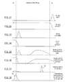
- FIG. 31is a diagram indicating the relative luminosity of light emitted by an infrared LED, according to an embodiment of the present invention.
- FIG. 32is a diagram indicating the relative luminosity of light detectable by an infrared LED, according to an embodiment of the present invention.
- FIG. 33is a diagram indicating the relative luminosity of light emitted by a blue LED, according to an embodiment of the present invention.
- FIG. 34is a diagram indicating the relative luminosity of light detectable by a blue LED, according to an embodiment of the present invention.
- FIG. 35is a diagram indicating the relative luminosity of light emitted by a blue LED, which includes light converted by a wavelength conversion material, according to an embodiment of the present invention.
- FIG. 36is a diagram indicating the relative luminosity of light detectable by a blue LED, which includes light converted by a wavelength conversion material, according to an embodiment of the present invention.
- FIG. 37is a diagram indicating the relative luminosity of light to be detected in an example, according to an embodiment of the present invention.
- FIG. 38is a diagram indicating the relative luminosity of light by a detected in an example, which has been converted by a wavelength conversion material, according to an embodiment of the present invention.
- FIG. 39is a block diagram of detecting an object in an environment, according to an embodiment of the present invention.
- FIG. 40is a flowchart illustrating the operation of FIG. 39 , according to an embodiment of the present invention.
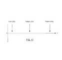
- FIG. 41is a time line relating to the events of the flowchart of FIG. 39 , according to an embodiment of the present invention.
- FIG. 42is a block diagram of an array of light emitting semiconductor devices to communicate data light using multiple channels, according to an embodiment of the present invention.
- FIG. 43is a diagram indicating the relative luminosity of the channels generated by the array of FIG. 42 .
- FIG. 44is a block diagram of detecting a substance in the environment, according to an embodiment of the present invention.
- FIGS. 45A , C, and Eare diagrams indicating the relative luminosity of the channels generated by the array of FIG. 44 .
- FIG. 46is a block diagram of detecting a substance in the environment using a wavelength conversion material, according to an embodiment of the present invention.
- FIGS. 47A-Eare diagrams indicating the relative luminosity of the channels generated by the array of FIG. 46 .
- FIGS. 48-51are schematic diagrams showing a correlation of data sensed in a data light using the lighting system according to an embodiment of the present invention to an image.
- FIG. 52is a diagram of an image created from sensed environmental light, according to an embodiment of the present invention.
- FIG. 53is a diagram of an image created from sensed environmental light, according to an embodiment of the present invention.
- FIG. 54is a diagram of an image created from sensed environmental light, according to an embodiment of the present invention.
- FIG. 55is a top plan view of an array of nodes located along a roadway, according to an embodiment of the present invention.
- FIG. 56is a front perspective view of an object sensed on the roadway illustrated in FIG. 55 , according to an embodiment of the present invention.
- the wavelength sensing lighting system 10may also be referred to as a lighting system 10 , system, device, embodiment, or the invention. Alternate references to the wavelength sensing lighting system 10 in this disclosure are not meant to be limiting in any way.
- a person of skill in the art, after having the benefit of this disclosure,will appreciate that the present invention may include embodiments that perform total, partial, and minimal conversion of a source light 42 into a converted light 46 . Additionally, skilled artisans will appreciate that, in embodiments with partial wavelength conversions, the remaining, unconverted source light 42 may be combined with the converted light 46 to be directed in the desired output direction, for example, to illuminate a space or to sense a condition in the environment.
- a light sourceis disclosed as a component of the lighting system 10 , according to an embodiment of the present invention.
- the light sourcemay be a light emitting semiconductor device 40 , which may be referenced throughout the following disclosure.
- a sensormay be discussed to sense environmental light 48 .
- the sensormay be a light source, such as light emitting semiconductor device 40 .
- the light emitting semiconductor device 40may include, among other devices, a light emitting diode (LED).
- the operation of the sensormay be performed by a light source, such as a light emitting semiconductor device 40 .
- the light emitting semiconductor device 40should be assumed to collectively include the light source and the sensor in at least one embodiment of the present invention.
- a controller 61may be discussed to analyze the environmental light 48 sensed by the sensor and control the emission of illuminating light 44 by the light source.
- the sensor and the light sourcemay be a light emitting semiconductor device 40 .
- the controllermay collectively include an analysis processor to analyze sensed environmental light 48 and a lighting controller 61 to control emitting illuminating light 44 .
- the controller 61may be a computerized device capable of sending, receiving, and analyzing data and electronic signals.
- the controller 61may control one or more light source, which may be included in an array 39 .
- the functionality of the controller 61should not be limited to light source controlling operations.
- the controller 61may additionally accept and analyze data or electronic signals received from one or more sensor.
- the controller 61may perform the operations of both an analysis processor and a lighting controller 61 , among numerous other operations that would be apparent to those skilled in the art. Skilled artisans will additionally appreciate that the controller 61 may be described broadly herein as a computerized device to perform computational operations, including processing data.
- a light sourcefor example, and without limitation, electroluminescent, laser, incandescent, and fluorescent light sources.
- the light sourcemay be discussed in regard to a specific embodiment of a light emitting semiconductor device 40 , a person of skill in the art will appreciate that additional light sources may be included with the operation of the various embodiments of the present invention, are intended to be included within the scope of the same. As a result, skilled artisans should not view the use of a light emitting semiconductor device 40 through this disclosure as limiting the scope of the light source.
- a light emitting semiconductor device 40may be used as a lighting device and/or sensor, which may emit illuminating light 44 and/or detect environmental light 48 from a plurality of directions. More specifically, and without limitation, an LED may be operable as a photodiode in replacement or addition to being a light emitter. LEDs are also capable of detecting incident light and producing an output voltage dependant on the intensity and the wavelength of such incident light.
- the lighting system 10may advantageously be implemented using an LED as a source of light emission and device for light detection, advantageously decreasing the complexity and manufacturing cost of the system 10 .
- a light emitting semiconductor device 40such as an LED
- a dedicated sensorsuch as a photodiode or a phototransistor
- light emitting semiconductor devices 40can provide enough sensitivity to allow their use as photodetectors for a plurality of applications consistent with the scope of the present invention.
- the LEDmay perform significantly the same operation as the dedicated photodiode.
- the LEDmay be switched between an emitting circuit, detecting circuit, and any other circuit, as it has been contemplated in accordance with an embodiment of the present invention.
- the LEDmay be sensitive to a wavelength range that is equal or lesser than the light that would be emitted by the LED.
- an LED operating as a sensormay typically detect light comprised of wavelengths equal to and shorter than the wavelengths that could be emitted by the LED.
- sequential and temporally correlated PWM of individual LEDs of an array 39may be operated in conjunction with temporally correlated sensing function to sense one or more condition of an environment.
- a single LEDmay be powered to emit illuminating light. Additional LEDs in the array 39 may be used for detection of environmental light 48 (e.g., during one or more duty cycles).
- scanning along particular geometries of the array 39can be used to resolve environmental signals, e.g., scanning along the vertical, horizontal, or diagonals of a rectangular or otherwise shaped array 39 .
- multi-color detection of environmental light 48including the use of metameric whites, can be used for greater resolution.
- Signal processing of the sensed data correlated with the illuminating light 44is used to characterize the environment. Mathematical analysis and signal processing techniques including Fourier transforms may be used to analyze the data.
- opticsmay be applied to one or more light emitting semiconductor devices 40 , or portions of light emitting semiconductor devices 40 included in the array 39 or across the network 69 , to improve the resolution at which a condition of the environment is detected.
- the resolutionmay be improved by allowing one or more light emitting semiconductor device 40 to detect different regions of an illuminated space. For example, LEDs may illuminate and/or detect multiple directions substantially simultaneously.
- an infrared LEDmay be included in a circuit as a photodiode.
- the infrared LEDmay emit illuminating light 44 with an approximate wavelength of 1400 nanometers. This may result in the infrared LED being usable as a photodetector to detect infrared light with wavelengths shorter than 1400 nanometers, visible light, and ultraviolet light.
- the illuminating light 44 emitted by the infrared LEDmay not be detected by a human without first being converted into visible light.
- a blue LEDmay be included in a circuit as a photodiode.
- the blue LEDmay emit illuminating light 44 with an approximate wavelength of 460 nanometers.
- This illuminating light 44may include high efficacy light which would be visible to humans.
- the blue LEDmay only be capable of detecting environmental light 48 with wavelengths shorter than 460 nanometers, which may include additional blue light and ultraviolet light, without performing some wavelength conversion operation on the environmental light 48 prior to detection.
- an array 39may include a plurality of blue LEDs and a plurality of infrared LEDs.
- the blue LEDsmay emit an illuminating light 44 that may be detectable to humans.
- the infrared LEDsmay detect an environmental light 48 within the visible spectrum. In this example, infrared LEDs would be able to detect at least part of the light emitted by the blue LEDs.
- one or more wavelength conversion material 30may be located between the LED and the environment to convert the wavelength range of light.
- the wavelength conversion material 30may perform a Stokes shift, wherein the conversion material 30 may absorb one or more photon, an elementary particle of light, from a source light 42 .
- the absorbed photonmay cause the conversion material 30 to enter an excited state.
- the conversion material 30may then emit a photon, allowing the conversion material 30 to relax from the excited state as it emits converted light 46 .
- the photon of the converted light emitted by the conversion material 30 during a Stokes shiftmay have less energy than the absorbed source light photon.
- Another type of wavelength conversion material 30may perform an anti-Stokes shift, wherein the conversion material 30 may emit a converted light 46 with higher energy, and thus shorter wavelengths, than the absorbed source light 42 .
- the higher energy of the converted light 46 resulting from an anti-Stokes shiftmay result from the combining of two or more photons of a lower energy state to create one photon of a higher energy state. This process may be known generally to skilled artisans as photon upconversion.
- the higher energy of the converted light 46 emitted by an anti-Stokes conversion material 30may be due to dissipation of thermal phonons in a crystal lattice, as will be understood by a person of skill in the art.
- a wavelength conversion material 30may include one or more conversion materials.
- the wavelength conversion material 30may include two types of phosphors to convert a blue source light into yellow and red converted lights.
- the conversion material 30may include a first conversion material 30 to perform a Stokes shift and a second conversion material 30 to perform an anti-Stokes shift.
- the first conversion material 30may convert the blue light emitted by a blue LED into white light, which may be more visually pleasing to an observer.
- the second conversion material 30may convert a source environmental light 48 into blue or ultraviolet light, which may be detected by the blue LED.
- the LEDmay emit and detect light within a significant range of the visible spectrum with respect to the respective wavelength conversions.
- a Stokes conversion of infrared light and an anti-Stokes conversion of blue lightmay be inconsequential to the operation, as the conversion may simply convert a portion of the source light 42 into converted light 46 outside of the visible spectrum.
- illustrative wavelength rangeswill now be discussed in relation to the light emitted and detected by a light emitting semiconductor device 40 , such as an LED. The following discussion will be directed to using an LED as the light emitting semiconductor device 40 . However, a person of skill in the art will appreciate that additional light emitting semiconductor devices 40 may be included in the lighting system 10 , according to an embodiment of the present invention, and without limitation. Additionally, the illustrative waveforms illustrated in FIGS. 31-34 contemplate the emission of illuminating light 44 and the detection of environmental light 48 without the use of a conversion material 30 to perform a wavelength conversion.
- FIG. 31illustrates the illuminating light 44 that may be emitted by an illustrative infrared LED, which may include illuminating light 44 characterized by long wavelengths.
- the wavelength range of the illuminating light 44 emitted by the infrared LEDsmay be outside of the visible spectrum.
- FIG. 32illustrates the environmental light 48 may be detected by the infrared LED, which may include a wavelength range of environmental light 48 with wavelengths less than the illuminating light 44 emitted by the infrared LED. Since environmental light 48 in the visible spectrum would include light defined by wavelengths shorter than infrared light, the infrared LED may detect substantially the entire wavelength range of environmental light 48 in the visible spectrum.
- FIG. 33illustrates the illuminating light 44 that may be emitted by the blue LED, which may include illuminating light 44 characterized by relatively short wavelengths.
- the wavelength range of the illuminating light 44 emitted by the blue LEDsmay be included in the visible spectrum, however toward the narrow wavelength range of visible light.
- FIG. 34illustrates the environmental light 48 that may be detected by the blue LED, including a small wavelength range of visible light that may include environmental light 48 characterized by shorter wavelengths than the blue illuminating light 44 emitted by the blue LED. Since the blue LED may not detect wavelength longer than the blue light emitted by the blue LED, it may not be able to detect a significant wavelength range of environmental light 48 in the visible spectrum.
- FIGS. 35-36the light emitted and detected by a blue LED that includes a conversion material 30 between the LED and the environment will now be discussed. More specifically, a blue LED with a conversion material 30 capable of performing a Stokes shift and an anti-Stokes shift, according to an embodiment of the present invention, will now be discussed.
- FIG. 35illustrates the illuminating light 44 that may be emitted by the blue LED, which may include illuminating light 44 characterized by relatively short wavelengths.
- FIG. 35additionally may include a wavelength range of illuminating light 44 that has been converted by the conversion material 30 to approximately the wavelength range of yellow light. Skilled artisans will appreciate that the blue source light 42 emitted by the blue LED and the yellow converted light 46 emitted by the conversion material 30 may be combined to create approximately white light.
- the environmental light 48 that may be detected by the blue LEDmay include a small wavelength range of visible light, which may include environmental light 48 with wavelengths shorter than the blue illuminating light 44 emitted by the blue LED.
- the wavelength range of detectable environmental light 48may additionally include environmental light 48 characterized by longer wavelengths than the light natively detectable by the blue LED.
- the anti-Stokes conversion material 30may convert the natively undetectable wavelengths of a environmental source light 42 into converted light 46 detectable by the blue LED. Since the blue LED may detect wavelengths shorter than its emittable blue light that, and since the conversion material 30 may convert the long wavelength light into short wavelength light, the blue LED may then be able to detect a significant wavelength range of the visible spectrum.
- a model environmental light 48that includes a peak of light to be detected by the lighting system 10 , according to an embodiment of the present invention.
- the aforementioned peak of environmental light 48is indicated as the point 91 .
- the blue LEDmay emit illuminating light 44 defined by a shorter wavelength range than the wavelength range of environmental light 48 indicated by point 91 . Since the blue LED may not natively detect environmental light 48 with wavelengths longer than the light it emits, the blue LED may not be able to detect the peak of environmental light 48 indicated by point 91 of FIG. 37 without a prior wavelength conversion, such as an anti-Stokes conversion.
- the wavelength range of environmental light 48 indicated by point 91may be absorbed by a wavelength conversion material 30 as source light 42 .
- the wavelength conversion material 30may then emit a converted light 46 that includes at least part of the peak of light indicated by point 91 , but characterized by a lower wavelength range than which the peak of light indicated by point 91 was absorbed by the conversion material 30 . This shift of wavelengths is illustrated in FIG. 38 .
- the converted peak of light indicated by point 91may then be emitted by the conversion material 30 at with shorter wavelengths than the wavelength range of illuminating light 44 emittable by the blue LED, thus allowing the peak of light indicated by point 91 to be detected by the blue LED.
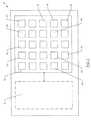
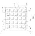
- An array 39 of light sources and sensorsmay be comprised of light emitting semiconductor devices 40 , which may perform the operation of the light source and the sensor. More specifically, and without limitation, the array 39 may include a plurality of LEDs configured to operate to emit illuminating light 44 and detect environmental light 48 .
- the array 39 of LEDsmay include one or more types of LEDs, configured to emit and detect different wavelength ranges of light.
- the array 39may include one or more of a blue LED, monochromatic LED, white LED, infrared LED, and any other light emitting semiconductor device 40 .
- Each LED or other light source included in the array 39may additionally have a wavelength conversion material 30 located between the respective light source and an environment.
- the wavelength conversion material 30may convert the wavelengths of the light transmitted between the light emitting semiconductor device 40 and the environment.
- the array 39may detect a plurality of discrete and/or overlapping wavelength ranges of environmental light 48 , which may be analyzed by the controller 61 to determine a condition of the environment.
- the array 39may include light sources and sensors, which may be light emitting semiconductor devices 40 , in single- or multi-dimensional configurations. For example, an approximately linear length of light emitting semiconductor devices 40 may be included in a one-dimensional array. Additionally, a plane of light emitting semiconductor devices 40 may be included in a two-dimensional array. The plane of light emitting semiconductor devices 40 may be configured in, but not limited to, rectangular or circular arrays. Furthermore, three-dimensional array 39 may include light emitting semiconductor devices 40 located on different planes from one another in the array 39 , which may emit illuminating light 44 and detect environmental light 48 from a plurality of directions.
- a multi-dimensional array 39may include a plurality of light emitting semiconductors devices 40 to emit illuminating light 44 in an outward direction, independent of one another.
- An example of this embodimentmay include light emitting semiconductors being located on a surface of a spherical object and configured to emit light in a direction projecting outward from the center of the spherical object.
- the multi-dimensional array 39may be configured to at least partially enclose a space.
- An example of this embodimentmay include light emitting semiconductors being located on ceilings, walls, floors, and other points of a room.
- a person of skill in the artwill appreciate additional configurations of multi-dimensional arrays 39 to be included in the scope and spirit of the present invention, after having the benefit of this disclosure.
- the environmental light 48 detected by the LED, or other light emitting semiconductor device 40may be communicated to a controller 61 or other signal processing device.
- controller 61may describe a single controller 61 that may analyze the environmental light 48 sensed by the LED, light emitting semiconductor device 40 , or other sensor, and control the emission of illuminating light 44 by the LED, light emitting semiconductor device 40 , or other light source.
- controller 61may include multiple controllers 61 , such as an analysis processor to analyze sensed environmental light 48 and a lighting controller 61 to control emitting illuminating light 44 .
- the analysis processor and the lighting controller 61may be communicatively connected, and may optionally operate separately or as one monolithic unit.
- information generated by one or more photodetector, or other data comprising light detected by a sensormay be received and processed by an analysis processor to generating information about the environment.
- the processed datamay be used to determine or infer information about the environment such as, but not limited to, object detection, location, motion, mass, direction, size, color, heat signature, or other information that may be associated with an object or the environment.
- environmental light 48 sensed by a photodetector or other sensormay be processed by an operatively connected controller 61 or processor 62 .
- the datamay be used to control one or more light sources to emit illuminating light 44 , which may include data light 45 to be received by a sensor or photodetector.
- one or more light sourcemay be modulated to confirm object detection, further resolve object features or location, or obtain additional data regarding the environment based on the data sensed by the sensor.
- the lighting system 10may analyze one or more condition of the environment. For example, the lighting system 10 may analyze whether motion is present in the environment. As another example, the lighting system 10 may determine the luminosity of environmental light 48 included in the environment. The determination of luminosity may be performed generally across all sensed environmental light 48 , or specifically with regard to one or more wavelength ranges of the environmental light 48 . Additionally, the sensors of the lighting system 10 may be configured to detect the presence of environmental light 48 with a discrete wavelength, such as, for example 445 nanometers.
- an array 39may include a plurality of light emitting semiconductor devices 40 , such as LEDs, configured to emit and detect light. Skilled artisans will appreciate the use of LEDs in this disclosure is not intended to limit the present invention to including solely LEDs as the light source and/or sensor.
- the LEDs included in the array 39may be modulated between states wherein illuminating light 44 is and is not emitted. During the states wherein illuminating light 44 is not being emitted, the LED may be used to detect environmental light 48 . The modulation of the LEDs may be controlled by the controller 61 .
- the LEDsmay be modulated between emitting and detecting light to allow detection of the light emitted by the same LED. This modulation may be performed by the controller 61 . To detect its own light, an LED and its corresponding switching circuit would have to switch between emitting illuminating light 44 and detecting environmental light 48 in less time than it would take for the illuminating light 44 to be emitted, reflected from the environment, and detected by the.
- one or more LED included in the array 39may be configured to sense the light emitted by one or more other LED included in the array 39 .
- the timing of the various LEDs included in the array 39may be controlled by the controller 61 .
- two or more LEDs in the array 39may be configured such that at least one LED may receive a desired wavelength range of environmental light 48 , which may include light previously or simultaneously emitted by another LED in the array 39 .
- the lighting system 10may determine a condition of the environment.
- a plurality of LEDsmay be included in the array 39 and configured to detect the light reflected from the environment that may have originated from other LEDs in the array 39 . As the number of LEDs in the array 39 may increase, the number of conditions detected in the environment may also increase.
- LEDs included in the array 39may be configured to emit and detect light emitted by any number of additional LEDs in the array 39 . In other words, the LEDs need not be paired to emit and detect the same light as one another. Additionally, multiple arrays 39 may be connected through a network 69 , allowing one array 39 to detect the light emitted by another array 39 . The data relating to the light detected by another array 39 may be intercommunicated between the emitting and detecting arrays across the network 69 .
- the environmental light 48 detected by the sensors of the array 39may be transmitted to a controller 61 as data.
- the controller 61may concatenate the data to create an image.
- the resolution of the image detected by the array 39may be determined relative to the number of points in the environment from which environmental light 48 is detected. For example, a simple one-dimensional array 39 including five forward-facing, linearly-aligned LEDs may be capable of producing an image with a resolution of one pixel by five pixels.
- a higher resolution imagemay be desired.
- a high resolution imagemay be produced, for example, by increasing the number of pixels to be included in the image. Due to the small scale at which semiconductor devices may be produced, a substantial number of light emitting semiconductors may be included in the array 39 to additionally sense environmental light 48 from a plurality of directions, effectively increasing the resolution of the respective image.
- Adding additional sensors, such as LEDs, to the array 39may increase the number of points in the environment to be detected by the array 39 .
- including the sensors on a piezoelectric substrate, which is intended to generally include a plurality of deformable substrate typesmay increase the points of an environment that may be sampled by a sensor. By allowing each sensor to detect environmental light 48 from multiple points in an environment, the size requirement of an array 39 needed to detect conditions of an environment with high resolution may be advantageously reduced.
- including a large number of LEDs located on piezoelectric substrates in an array 39may provide detection of conditions of an environment with increased resolution over sensors located on a fixed substrate.
- the array 39may be connected to, and intercommunicate with, additional arrays 39 as nodes in a network 69 .
- the environmental light 48 sensed by each sensor in the node and analyzed by the controller 61 of the node,may be intercommunicated between the nodes throughout the network 69 .
- the data detected by each nodecan be concatenated with data detected from other nodes to increase the resolution at which a condition of the environment with may be determined over the resolution available from a single node.
- the increased resolution of the environmental light 48 detected at each nodemay be collectively concatenated to produce a visual representation of one or more condition of the environment.
- the driving time of one node or array 39may be coordinated with the driving and/or detecting time of another node in the network 69 .
- An example of a driving timemay be the PWM timing and phase protocol for driving an array 39 or node for emitting illuminating light 44 and/or detecting environmental light 48 .
- the coordination of this operationmay be controlled by a controller 61 communicatively connected to the array 39 , light emitting semiconductor device 40 , or otherwise included in the node.
- the coordinationmay be used to control both emission and detection of light.
- a two-dimensional visual representation of a condition of the environmentmay be an image.
- the imagemay be formed by concatenating the luminosity and/or wavelength data gathered from each point in the environment.
- a plurality of imagesmay be concatenated to create a moving picture, or video, of the environment.
- the videomay be streamed directly to an interface device by transmitting data light 45 and/or using a data transmission protocol known within the art.
- the videomay also be stored in memory 64 , wherein it may be accessed, downloaded, and/or viewed concurrent or at a later time.
- the images created from the sensed environmental light 48may also be compared with previously or subsequently created images. For example, sequential images may be compared to detect differences between each image. The difference between the images may be analyzed to detect a condition, such as motion. Additionally, the controller 61 may further analyze the motion detected between a plurality of images to detect the distance and/or velocity of the motion. A person of skill in the art will appreciate that velocity is defined to include the rate and direction in which the position of an object may change. Skilled artisans will also appreciate that the images compared to detect motion, or another condition of the environment, may not be sequential.
- the lighting system 10may detect the distance between the system 10 and an object in the environment.
- the lighting system 10may tag or indicate light emitted from the light source as marker light 49 , which may be detectable by a sensor.
- the light source and the sensormay, for example, and without limitation, be an LED.
- the light indicated as marker light 49may be viewed as a segment of light that includes an identifying characteristic.
- the marker light 49may be included in illuminating light 44 emitted into the environment and environmental light 48 sensed from the environment.
- the illuminating light 44 that includes the marker light 49may be reflected from a point of reflection 50 in the environment, after which it may be received as environmental light 48 by a sensor, such as an LED configured to detect environmental light 48 .
- the marker light 49may include a specific wavelength range as the identifying characteristic.
- a pulse of marker light 49may be emitted by an LED into the environment with a wavelength of 485 nanometers.
- the marker light 49may be natively emitted or converted by a conversion material 30 to achieve the desired wavelength range that may indicate the marker light 49 .
- An LED operating to detect environmental light 48may subsequently sense the pulse of marker light 49 .
- the marker light 49may include one or more bits of digitally encoded information. This information may identify the segment of marker light 49 .
- the digitally encoded marker light 49may include a pattern of high and low values, such as zeros and ones, which may be sensed by a sensor and communicated to a controller 61 .
- the digitally encoded marker light 49 sensed in the environmental light 48may then be compared with the digital encoding of the emitted marker light 49 to determine whether the digitally encoded signal is the same.
- the controller 61may be connected to both the emitting LED and the sensing LED.
- the controller 61may detect the delay between the emission of the marker light 49 and the detection of the marker light 49 .
- the controller 61may analyze the delay to determine the relative distance of an object in the environment.
- At least one LEDmay detect the marker light 49 as it is being emitted by another LED included in the lighting system 10 , which may be communicated to the controller 61 , which may create an error by having effectively having approximately no delay.
- the controller 61may perform error detection by determining that the detection of marker light 49 without an accompanying delay may not have been reflected from a point of reflection 50 in the environment. In these instances, the controller 61 may disregard the sensed marker light 49 without an accompanying delay. The controller 61 may then subsequently detect the marker light 49 with an accompanying delay. This delay may be indicative that the marker light 49 has been reflected from a point of reflection 50 , which may be due to an object in the environment.
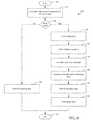
- FIGS. 39-41an illustrative operation of detecting a delay using marker light 49 will now be discussed.
- the block diagram of FIG. 39 and the flow chart 250 of FIG. 40along with the timeline of FIG. 41 , illustrate the operations of flowchart 250 plotted relative to the time of each operation.
- the delay detecting operationmay begin.
- the marker light 49may be emitted by light emitting semiconductor device 40 , which may be included in an array 39 of light emitting semiconductor devices 40 (Block 252 ).
- the marker light 49may then be reflected from a point of reflection 50 (Block 254 ).
- At least part of the reflected marker light 49may be directed back to the light emitting semiconductor device 40 , or array 39 of light emitting semiconductor devices 40 , which may detect the light. Additionally, the reflected marker light 49 may be directed to another light emitting semiconductor device 40 included in a network 69 connected node, which may intercommunicate with the node that emitted the marker light 49 .
- the reflected marker light 49may be included in environmental light 48 , which may be sensed by a light emitting semiconductor device 40 (Block 256 ).
- the controller 61may then determine the distance of the object from the lighting system 10 by analyzing the delay (Block 258 ). The operation may then terminate at Block 259 .
- the environmental light 48 detected by the sensors of the array 39or alternatively the sensors included within a node of the network 69 , to determine a three-dimensional representation of the environment.
- the distance of an object detected by sensors included in the array 39 or network 69may be concatenated to generate a three-dimensional model of the environment. As distances may be calculated from different angles, detail may be added to the three-dimensional model of the environment. Also, the three-dimensional model of the environment may be continually updated as the sensors continue to sample the environment. Like with images and videos, the three-dimensional model of the environment may be observed remotely by additional devices in the network 69 .
- the lighting system 10may analyze the environmental light 48 .
- a number of signal processing operationshave been discussed in the referenced and incorporated U.S. patent application Ser. No. 13/269,222. Additional signal processing operations may be included to recognize one or more pattern relative to the environment.
- Wavelength and intensity informationmay be distributed throughout a digital neural network for an in-depth analysis and identification of a source of interest. A neural network will be discussed in more detail below.
- the controller 61may analyze the data detected by the sensor, which may be an LED, to identify one or more condition of the environment.
- a condition of the environmentmay include objects, substances, or living beings in the environment.
- identificationmay include recognition of one or more object, such as, but not limited to, large vehicle, small vehicle, people, a specific person, animal, substance and other conditions of an environment that could be identified.
- the light emitting semiconductor device 40may sense environmental light 48 including a plurality of wavelength ranges.
- a dominant wavelengthmay be included in the wavelength sensed by the lighting system 10 .
- the dominant wavelengthmay be indicative of a desired condition to be detected in the environment, such as, for example, color.
- the dominant wavelengthmay additionally be used to sense the presence of a substance in an environment, as the controller 61 may detect the presence or absence of the dominant wavelength from the sensed environmental light 48 .
- the dominant wavelengthmay be defined by the controller 61 .
- the controller 61may be programmed to detect dominant wavelengths that can be associated with a specific condition to be sensed in the environment.
- the sensed conditionmay include the presence of a substance, for example, and without limitation, a gas, biological agent, explosive compound, neurotoxin, element, chemical composition, smog, particulate, or other substance.
- a gas, biological agent, explosive compound, neurotoxin, element, chemical composition, smog, particulate, or other substanceA person of skill in the art will appreciate additional conditions that may be sensed by detecting the presence or absence of a dominant wavelength, which is intended to be included within the scope of the present invention.
- An objectmay be recognized or identified with various levels of clarity and resolution.
- the resolution of an identified objectmay be relative to the amount and quality of the information provided to the neural network.
- a network of many nodes, each node including a controller 61 , light source, and sensor,may provide enough resolution to allow for the identification of a person with a medium degree of confidence (80% or above), or a high degree of confidence (95% of above).
- An artificial neural networkmay include a plurality of interconnected nodes to share the collection and processing of data. Each node in a neural network may operate similar to the neurons of a biological neural network, processing information using an interconnected network of simple units.
- the neural networkmay use a learning procedure, such as parallel distributed processing, to improve the accuracy of the analysis performed by at least one of the nodes included in the network 69 .
- a person of skill in the artwill appreciate additional learning procedures, in substitution or addition to parallel distributed processing, to be included within the scope of the present invention. Additionally, skilled artisans will appreciate additional artificial learning procedures that may analyze a determination to improve the accuracy of subsequent determinations to be included within the scope of the present invention, such as but not limited to, machine learning.
- the choice of the neural network for recognizing and identifying an objectmay be based upon the configuration of the network 69 of nodes, each of which may include a controller 61 and at least one light emitting semiconductor device 40 , for example, an LED.
- the selection process for selecting a type of neural networkmay begin with a detailed analysis of a certain number of input data streams for LEDs relating to the sensed environmental light 48 .
- the neural networkmay then focus on determining correlations of LED responses with exposure to their respective light sources. LEDs spaced relatively far apart from each other will likely exhibit low correlation among different LEDs. Conversely, LEDs placed in an array 39 very close to each other may show high correlation numbers. The objective is to find the LEDs with the largest responses and correlations to enable achieving the highest performance in any subsequent neural network.
- a neural networkmay be trained to recognize different objects. More specifically, a neural network may be trained to identify one object from another of similar, but not identical, characteristics.
- the trainingmay be performed using various techniques, such as, for example, use of back propagation of gradient-descent computed error corrections for weights and biases.
- the back propagation techniquemay involve feed forwarding an input training pattern, computing the associated error between computed outputs and training vector outputs, back propagating the associated errors, and adjusting weights and biases.
- machine learningmay be used to improve the accuracy of the analysis performed by the controller 61 .
- machine learningmay include a series of analyses performed by a computerized device, such as the controller 61 , which may allow the computerized device to evolve its predictions based on empirical data included in memory 64 or detected by sensors.
- the controller 61 of the lighting system 10or collectively the controllers 61 of each node included in the lighting system 10 , may included as the computerized devices to analyze the environmental light 48 data detected by one or more sensor.
- the controller 61may make predictive determinations based on rules that have been dynamically created through data programmed in the memory 64 and the recording of feedback relating to prior determinations. Through inductive inference, the lighting system 10 may classify the sensed data using pattern recognition. This classification may allow the lighting system 10 to learn, or become more likely to automatically recognize, complex patterns. Through machine learning, the lighting system 10 may additionally distinguish between patterns, allowing one or more controller 61 included in the lighting system 10 to make an intelligent prediction on the data received by the sensor.
- the lighting system 10 of the present inventionmay include various additional operations and determinations to improve the execution and accuracy of the analysis performed on the environmental light 48 sensed by the sensor and transmitted to the controller 61 .
- skilled artisanswill not limit the learning techniques to the aforementioned examples of neural networks and machine learning. Instead, those of skill in the art will appreciate a plethora of additional branches of advanced computing and artificial intelligence, including analyses based on pattern recognition and error detection, to be included within the scope of the present invention.
- the lighting system 10may include a plurality of nodes connected through a network 69 .
- Each nodemay include at least one of a light source, sensor, and controller 61 .
- the light source and the sensormay be included as a light emitting semiconductor device 40 , such as an LED.
- the nodesmay intercommunicate with one another through the transmission and receipt of data light 45 . If a node receives data light 45 that is addressed or intended for another node, the unintended recipient node may rebroadcast the data to be received by another node, such as the intended node.
- the nodes in the network 69may communicate, for example, by transmitting a digitally encoded data light 45 among the nodes in the network 69 .
- the data light 45may include modulated or otherwise controlled pulses, which may include transmittable data.
- the data light 45may be modulated using pulse width modulation (PWM), pulse interval modulation (PIM), or an additional modulation technique that would be appreciated by those of skill in the art.
- PWMpulse width modulation
- PIMpulse interval modulation
- the data transmitted in the data light 45may be transmitted at a high data rate.
- the lighting system 10may increase the quantity of data transmitted per channel and/or increase the number of channels.
- the data light 45may be transmitted with an increased modulation frequency signal.
- the light source emitting the data light 45may use rapidly decaying modulation techniques.
- the rapidly decaying modulationmay be accomplished, for example, by distributing the transmission of data light 45 across multiple light sources included in the array 39 .
- the controller 61 of the lighting system 10may distribute the emission of data light 45 among various light sources.
- the controller 61may overlap switching between active and inactive states across multiple light sources, which may advantageously provide faster switching than would be achieved by using a single light source. Additionally, including high speed switches may allow further increased switching, which may correspond to increased data rates.
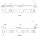
- the data light 45may include at least one channel through which data may be transmitted.
- a single channel transmission of data light 45may occur at or about 445 nanometers.
- the theoretical maximum rate at which data light 45 may be transmittedmay be bound by the rate at which the single channel may be modulated.
- the data light 45may be modulated across a plurality of channels.
- Each channel of data light 45may be defined respective to a characteristic of that channel, such as the wavelength of light at which the data light 45 is transmitted.
- each channelmay be directed to one or more node within the network 69 .
- all channelsmay be directed to the same node.
- a number of channels of data light 45 transmitted from a first nodemay be directed to any number of separate nodes, each of which receiving one or more channels of data light 45 .
- Nodesmay address one another sequentially and/or in parallel. In other words, each node may address one or more additional nodes substantially simultaneously by transmitting data light 45 over a plurality of channels.
- the five-channel transmission of data light 45may include five streams of data to be received by another node in the network 69 .
- the five data channelsmay be transmitted at five different wavelengths of light.
- the wavelengths of each data channelmay be generated by including various conversion materials 30 A, 30 C, 30 D, 30 E, and 30 F adjacent to one or more light sources, such as light emitting semiconductor devices 40 .
- the five channels of data light 45may be transmitted at 445, 460, 485, 495, and 510 nanometers. These wavelengths may appear visually similar to human observers, yet would be very distinct to a sensor configured to detect the discrete wavelengths.
- Each channel of data light 45may be emitted by a respective light source, or wavelength conversion material 30 that may receive and convert the illuminating light 44 from a light source, at the appropriate wavelength.
- the channels of data light 45are illustrated in FIG. 43 , with each channel correlating to a conversion material 30 applied to the array 39 of lighting emitting semiconductor device of FIG. 42 .
- each sensormay discretely detect the data light 45 at each wavelength respective to the channel it has been emitted.
- the lighting system 10may use a wavelength conversion material 30 to convert environmental light 48 prior to being detected by the sensor.
- the detected channels of data light 45may then be communicated to the controller 61 , which may combine the data from each channel to receive the data included in the data light 45 .
- embodiments of the present inventionmay include any number of channels at which data light 45 may be transmitted. Additionally, a person of skill in the art will appreciate that virtually any wavelength, or range of wavelengths, may be used to include light at a given channel. As such, a person of skill in the art will not view the use of three channels, or the specified illustrative wavelengths of each channel, as limiting the present invention in any way.
- the sampling rate at which the environmental light 48 may be detectedcan be variable.
- the sampling ratemay be varied manually, dynamically, and/or according to a predetermined pattern. For example, if the lighting system 10 detects that minimal changes exist between sampling periods of the environment, the lighting system 10 may decrease the sampling rate at which environmental light 48 is detected. Alternatively, if the lighting system 10 detects a high degree of variance between sampling periods, the lighting system 10 may increase the sampling rate to detect changes in the environment with an increased level of detail.
- the data light 45may be transmitted at one or more bit rate.
- the bit ratemay be adjusted relative to a plurality of factors, including the quantity of data to be transmitted, the quantity of errors detected in the data transmission, distance at which the data may be transmitted, or any number of additional factors that may affect data transmission bit rates.
- the bit rate at which data light 45 is transmittedmay be dynamically variable according to the type and quantity of data being transmitted.
- the nodemay transmit a series of images detected from the environment to another node.
- the imagemay include varying levels of detail, which may correspond to a varying quantity of data to be transmitted.
- the bit rate at which the datamay be transmitted.
- Inclusion of a dynamically variable bit ratemay allow for the allocation of additional data transmission resources for more complex, and therefore data intensive, portions of a data transmission.
- a dynamically variable bit ratemay conserve the amount of data transmitted for relatively simple portions of a data transmission.
- the data included in the data light 45may be compressed prior to transmission to another node, or other device, in the network 69 . Additionally, the data may be decompressed after it has been received by a node. Data compression may reduce the amount of data to be included in the data light 45 , further increasing the effective amount of data that may be transmitted using a channel of data light 45 . Skilled artisans will appreciate data compression, as many methods of which are known within the art.
- a nodemay determine its location the environment with respect to other nodes connected in the network 69 .
- a nodemay also determine the location of other nodes in the environment.
- Multiple nodes within the network 69may be aware of a plurality of details relating to additional nodes in the network 69 , including the location, operation, and status of the respective nodes.
- a nodemay use a location determining operation, such as, for example, triangulation, to determine its location in an environment.
- a nodemay receive a signal from a plurality of other nodes.
- the signalmay include information to be analyzed by the receiving node to determine its location.
- a signal used to determine the location of a nodemay include an identification of the transmitting node, an indication that the signal is transmitted to determine a location, a time stamp from which a transmission delay may be calculated, and/or additional information that would be apparent to a person of skill in the art.
- the lighting system 10may include one or more wavelength conversion materials 30 that are sensitive to wavelength ranges that may be emitted or absorbed by a substance, such as a biological agent or bomb dust.
- a wavelength conversion material 30may be used in connection with the sensor, which may be a light emitting semiconductor device 40 , to determine a difference between a detected level of an indicative wavelength range and the normal level of an indicative wavelength range. If the difference detected is indicative of the substance, for example, the difference being above a threshold level, the lighting system 10 may generate an alert which may be received by another device connected to the network 69 , or a user.
- Applications for this embodimentmay include airports, embassies, government buildings, base camps, or virtually any additional location wherein the detection of a substance in an environment may be desired.
- the lighting system 10may operate to detect the substance in an environment.
- the lighting system 10may include a conversion material 30 between the environment and the sensor to convert a difference in luminosity of one or more wavelength of light reflected, emitted, or absorbed from a substance in the environment to be detectable by the sensor.
- the light source and the sensormay be included as a light emitting semiconductor device 40 , such as an LED.
- a light emitting semiconductor device 40such as an LED.
- Reference to a light emitting semiconductor device 40 and/or an LEDis not intended to be limiting the light source and/or sensor to be included in the present invention.
- the accompanying waveformshave been provided as relative waveforms, and should not be considered limiting.
- the detectable substancemay reflect, emit, or absorb light within a wavelength range respective to the substance.
- a conversion material 30may be included between the LED and the environment that is sensitive to a wavelength range corresponding with the wavelength range of the detectable substance.
- Substancesmay include toxins, biological agents, contaminants, molecules, or virtually any other substance that may absorb or emit a detectable wavelength range of light.
- Illuminating light 44may be emitted from a light emitting semiconductor device 40 into the environment.
- the relative wavelength range of the emitted illuminating light 44is illustrated in FIG. 45A .
- At least part of the illuminating light 44may be reflected from the substance 32 as environmental light 48 .
- the substance 32may absorb at least part of the illuminating light 44 , resulting in a wavelength range of illuminating light 44 that was originally emitted by the light emitting semiconductor device 40 not being included in the reflected environmental light 48 .
- the reflected environmental light 48 indicative of a substance 32is illustrated in FIG. 45C .
- the light emitting semiconductor device 40may detect the environmental light 48 , which may be analyzed by the controller 61 to determine a difference between the emitted illuminating light 44 and the detected environmental light 48 .
- the differenceis represented in FIG. 45E .
- the controller 61may then compare the wavelength range at which the difference of light occurs with information included in the memory to determine which material is present in the environment. Alternatively, the controller 61 may compare the difference of light with information included in the memory of another device connected to the network 69 .
- Illuminating light 44may be emitted from a light emitting semiconductor device 40 to be received by a conversion 30 material as source light 42 .
- the emitted illuminating light 44is illustrated in FIG. 47A .
- the conversion material 30may convert the source light 42 into a converted light 46 , which may be emitted into the environment as illuminating light 44 .
- the converted illuminating light 44 , 46is illustrated in FIG. 47B .
- At least part of the illuminating light 44may be reflected from the substance 32 as environmental light 48 .
- the substance 32may absorb at least part of the illuminating light 44 , resulting in a wavelength range of illuminating light 44 that had originally been emitted by the light emitting semiconductor device 40 not being included in the reflected environmental light 48 .
- the partially reflected environmental light 48 indicative of a substance 32is illustrated in FIG. 47C .
- the environmental light 48 indicative of the substance 32may be received by the conversion material 30 as source light 42 to be converted into converted environmental light 46 , 48 , which may be received by the light emitting semiconductor device 40 .
- the converted environmental light 46 , 48is illustrated in FIG. 47D .
- the light emitting semiconductor device 40may detect the environmental light 48 , which may be analyzed by the controller 61 to determine a difference between the emitted illuminating light 44 and the detected environmental light 48 . The difference is represented in FIG. 47E .
- the controller 61may then compare the wavelength range at which the difference of light occurs with information included in the memory 64 to determine which material may be present in the environment.
- the controller 61may consider the preceding wavelength conversion as it performs analysis on difference detected in the environmental light, for which it may compensate. Alternatively, the controller 61 may compare the difference of light with information included in the memory 64 of another device connected to the network 69 .
- the lighting system 10may generate an alert upon the occurrence of an event.
- the alertmay be transmitted to an additional node included in the network 69 , an otherwise network connected device, or displayed to an observer.
- An event that may initiate an alertmay involve the detection of a condition in the environment, such as the presence of an object or substance.
- the eventmay alternative initiate an alert if a condition rises above a threshold level, which may be predefined or dynamically determined.
- the communication across the network 69may be performed digitally.
- the communication of an alertmay be performed by emitting an alerting wavelength, or a wavelength that has been designate to indicate that an alert has been generated.
- an alertmay be communicated as the emission of visual light, for example, flashing red light upon the detection of a hazardous condition in the environment.
- a synchronization signalmay be emitted among a plurality of nodes to synchronize the operation of the nodes.
- the nodesmay be synchronized to target, analyze, or confirm analysis of a condition of the environment.
- the synchronization signalmay be used to synchronize the images or other visual representations of the environment.
- the synchronization signalmay synchronize the shared processing efforts across at least part of the nodes included in the network 69 .
- the analysis of the environmental light 48 detected in the environment, or other conditions detected in the by a sensormay be shared across multiple nodes included in a network 69 .
- the shared analysis of datamay be performed, for example, using distributed computing, which would be appreciated by a person of skill in the art.
- distributed computingmay organize a complex computation into multiple discrete computations, each of which may be distributed to one or more nodes across a network 69 to be performed in parallel. After the discrete computations have been completed, they results may be combined to a result from the complex computation.
- a wavelength conversion material 30may be included between the light source and the environment to create a biologically affective light.
- the source light 42may be a light emitting semiconductor device 40 , such as, for example, an LED.
- the biologically affective lightmay include one or more wavelength ranges that may induce a biological effect in an organism.
- a conversion material 30may be included to convert a source light 42 into a converted light 46 including wavelengths that increase the production of biological chemicals that affect alertness, such as melatonin.
- the lighting system 10may detect that a person is present in the environment.
- the lighting system 10may make this determination by analyzing information received from detecting the environmental light 48 .
- Such informationmay include heat signatures, proximate variance, movement, images, videos, patterns, or other detected information.
- the lighting system 10may then enable one or more light source with an adjacently located biologically affective conversion material 30 to emit biologically affective converted light 46 .
- the biologically affective lightmay induce the onset of sleepiness for the people in the environment. Due to the effects of sleepiness, the people in the room may become less alert, slowing response times, and providing for a tactical advantage for any subsequent operations performed in that environment.
- the light sources and sensorsmay be light emitting semiconductor device 40 .
- the light emitting semiconductor devices 40may be configured in an eight-by-eight square array 39 .
- any number of light emitting semiconductor devices 40may be configured in an array 39 of virtually any shape, as it may be included in single- or multi-dimensional configurations.
- Operation of the light emitting semiconductor devices 40 included in the array 39may be selectable between emitting illuminating light 44 and detecting environmental light 48 .
- the light emitting semiconductor devices 40may be selectable between emitting and detecting at intervals independent of one another, overlapping intervals, or substantially simultaneously. Additionally, the light emitting semiconductor devices 40 may be selectable between emitting and detecting repeatedly, effectively cycling through periods of light emission and detection.
- the light emitting semiconductor device 40may detect the environmental light 48 in the environment, the light emitting semiconductor device 40 may transmit data regarding the detected environmental light 48 to the controller 61 for analysis.
- the controller 61may concatenate each point of data, as may be sensed by the light emitting semiconductor devices 40 , to create an image.
- the imagemay have a resolution relative to the number of light emitting semiconductor devices 40 included in the array 39 and the number of points in the environment from which environmental light 48 may be sensed by each light emitting semiconductor device 40 .
- This illustrative imagemay have been detected by a fixture located above a target environment, facing downward.
- the relative luminosity of light detected in the environmentwhich may be indicative of an object being located in the environment, may be represented by a scale of values.
- the scale of valuesranges from zero to four.
- the scale of valuesmay include any number of intervals between a minimum and maximum value.
- a plurality of objectsmay be located in the environment.
- a first and second objectmay be located approximately in the top half of the area to be sensed by the lighting system 10 . Since the tallest point of the object may be located near the object's center, the amount of light reflected from the environment proximate to the object may be greater than other points wherein the object is not present. Additionally, a third object may be located approximately in the bottom left portion of the area to be sensed by the lighting system 10 .
- the light emitting semiconductor device 40may sense a saturating amount of environmental light 48 from the first object at location (3,5), with varying levels of luminosity surrounding the saturated areas.
- the light emitting semiconductor device 40may sense a saturating amount of environmental light 48 from the second object at location (6,6), with varying levels of luminosity surrounding the saturated areas.
- the light emitting semiconductor device 40may sense a saturating amount of environmental light 48 from the third object at locations (3,1) and (3,2), with varying levels of luminosity surrounding the saturated areas.
- the controller 61may process the levels sensed by the light emitting semiconductor devices included in the array 39 to determine that an object is present in the environment that the lighting system 10 may detect. The controller 61 may then, for example, control the light emitting semiconductor device 40 to increase the emission of illuminating light 44 as a result of an object being present in the environment. The controller 61 may additionally analyze the proximate variance, which may be used to determine the location and movement of the objects, to make a determination of condition in the environment. For example, the controller 61 may determine that the first and second objects are likely humans engaged in a conversation. The lighting system 10 may then enable a microphone, which may be included in, or connected to, the lighting system 10 to sense an additional condition of the environment, such as conversation dialog in the present example. A person of skill in the art will appreciate additional sensors that may sense information from an environment that would be included in the scope of the present invention.
- the lighting system 10may communicate the sensed conditions by using the data communications discussed above, such as transmitting data through a series of pulsed light emissions.
- the lighting system 10may transmit or relay the information sensed by the additional environmental sensors to one or more additional node, which may be included in the network 69 .
- the lighting system 10may continue to sample the environment by sensing the luminosity of environmental light 48 present in the environment. By continually sampling the environment, the controller 61 may analyze the sensed environmental light 48 to make further determinations regarding the conditions of the environment. Additionally, as additional nodes may be added to the network 69 , the computational power of the network 69 of nodes may be increased, respectively. This increase of computational power may be accomplished by, for example, distributed computing.
- Light emitting semiconductor devices 40may comprise different semiconductor materials and/or be located adjacent to different conversion materials 30 to detect the luminosity of light relative to different wavelengths. These wavelength based luminosities may be analyzed by the controller 61 to generate an image respective to the different wavelengths.
- An example of an image representative of multiple wavelength rangesmay include a color image.
- the relative luminosity of each sampled point in the environmentmay be converted into a visual representation, which may use color or shading to represent the luminosity and wavelength levels detected in the environment.
- a subsequent imagemay additionally be sensed by the lighting system 10 .
- the subsequent imagemay be sensed similar to the sensing operation described in relation to FIG. 48 .
- a subsequent sensing operationmay sense the objects located in the environment.
- the first and second objectsmay be located approximately in the same positions as wherein the environment was sensed or sampled in the example of FIG. 48 .
- the light emitting semiconductor device 40may sense a saturating amount of environmental light 48 from the first object at locations (3,5) and (3,6), with varying levels of luminosity surrounding the saturated areas.
- the light emitting semiconductor device 40may additionally sense a saturating amount of environmental light 48 from the first object at locations (7,5) and (7,6), with varying levels of luminosity surrounding the saturated areas.
- the controller 61may process the levels sensed by the light emitting semiconductors included in the array 39 to determine that the first and second objects is present in the field in which the lighting system 10 may sense.
- the controller 61may additionally determine that the object have not substantially relocated since the last sampling period.
- the controller 61may, however, determine that the light reflective patterns of the objects are shifting slightly between each sampling period.
- the controller 61may additionally determine, for example, that this shifting pattern is indicative of conversation.
- the light emitting semiconductor device 40may additionally sense a saturating amount of environmental light 48 from the third object at locations (7,1) and (7,2), with varying levels of luminosity surrounding the saturated areas. The relocation of the object between sampling periods may indicate that motion has occurred.
- the controller 61may then, for example, determine that a third person or object is patrolling the environment.
- the lighting system 10may continue to detect images from the environment, which it may compare to other images to detect further patterns. For example, if the person at the bottom of the screen continually moves in a substantially repeatable pattern, the lighting system 10 may determine with increased confidence that the person is patrolling than simply crossing the environment.
- the environmental light 48 sensed by the light emitting semiconductorneed not saturate the light emitting semiconductor to result in a sensed condition in the environment.
- the controller 61may analyze sensed environmental light 48 that does not include a saturating amount of environmental light 48 to determine a condition may exist in the environment. Additionally, a person of skill in the art will appreciate that as the levels of light detected by the light emitting semiconductor may increase, the accuracy of the analysis performed by the controller 61 may correspondingly be increased.
- a sensed environment of FIG. 50may be visually represented as an image, such as illustrated in FIG. 51 .
- the images of FIGS. 49 and 51may be concatenated into a series of images, for example, to form a video with each image being a frame of the video.
- the sensed image of FIG. 51may be compared to one or more other images sensed by the lighting system 10 to determine patterns and differences between the images.
- the patternsmay be analyzed to detect conditions in the environment, such as the presence of an object or person, movement, or other conditions.
- an array 39 of sensors capable of detecting a high resolution imagewill now be discussed along with FIGS. 52-54 .
- an array 39 of light sources and sensorswhich may be included as a light emitting semiconductor device 40 , may be located on a plane facing a detectable object.
- the array 39may be included on one or more walls, positioned in alignment to the face of a target person to be detected.
- one or more nodes including additional arrays 39may be communicatively connected at varying points in the environment to increase the resolution of the images and other conditions detected from the environment.
- an array 39 of sensorsmay detect an object in the environment with an increased level of detail than FIGS. 49 and 51 and other previous examples.
- the lighting system 10may sample an increased number of points in the environment, the resolution of the resulting image may be correspondingly increased.
- a further increased number of points being sampled by the lighting system 10 in the environmentmay result in a detected image of increasing resolution, which may clearly illustrate defining facial features.
- the facial features, or other defining features of a target person or object of interestmay be used identify the person or object of interest.
- an image of further enhanced resolutionmay be detected with sufficiently enough sensors directed to an object in the environment.
- the sensorsmay be may be light emitting semiconductor devices 40 .
- the sensorsmay be configurable to focus on a small area within the environment to better identify the object.
- the objectmay be the eye of a person in the environment to be identified.
- the lighting system 10may recognize the presence of an eye in the environment, to which defining features of the eye may be detected to identify the person with a high degree of accuracy.
- the sensors included in an array 39may be focused on a narrow area in the environment by including a deformable or piezoelectric substrate.
- the lighting system 10may detect conditions of an environment generally, indicating that a person exists in the environment. The lighting system 10 may then adjust the sensors to detect environmental light 48 from an angle to focus on a more narrow area within the environment, providing higher resolution.
- the number points from which conditions of the environment may be detectedwould remain approximately the same, but the area in which the points are concentrated may be reduced to increase the resolution of an image.
- the light emitting semiconductor devices 40 of the array 39may intelligently alternate between emitting illuminating light 44 , and sensing environmental light 48 .
- the direction in which each light emitting semiconductor devices 40 facesmay be movable, for example, by altering the deformable or piezoelectric substrate.
- the lighting system 10may adjust the light emitting semiconductor devices 40 to emit illuminating light 44 in a generally forward direction during a portion of its duty cycle. This forward emission may advantageously make the lighting system 10 appear significantly indistinguishable from a normal lighting device to human observers.
- the lighting system 10may sense environmental light 48 from a targeted space within the environment.
- the lighting systemmay sense environmental light 48 from the targeted space with high resolution, such as to focus on an object in the environment with enhanced wavelength detection.
- a substantial number of the light emitting semiconductor devices 40 in the arraymay be positionable to face the target object in the environment.
- This targeting operationmay allow the lighting system 10 to detect environmental light from an increased number of points within a concentrated space relative to the detectable object.
- the light emitting semiconductor devices 40may be positioned to again emit an illuminating light 44 in approximately the forward direction.
- the lighting system 10may detect a three-dimensional representation of the environment.
- the light sources and sensorsmay be included as a light emitting semiconductor device 40 .
- a plurality of light emitting semiconductor devices 40may be distributed throughout the environment to detect the distance of an object in the environment from the light emitting semiconductor device 40 .
- a plurality of light emitting semiconductor devices 40may determine the distance to an object from a plurality of angles, which may be located on a plurality of planes.
- the controller 61or multiple controllers 61 intercommunicating across a network 69 , may analyze the distances and angles detected by the light emitting semiconductor devices 40 in the lighting system 10 to determine the position of the object relative to the three-dimensional space of the environment.
- a plurality of lighting emitting semiconductor devices 40may be located within the environment to be sensed at differing locations.
- the light emitting semiconductor devices 40may be on different planes within the environment to sense environmental light 48 from differing angles and directions.
- One or more controller 61may analyze the sensed environmental light 48 from the plurality of angles and directions to construct a multidimensional representation of the environment.
- the controller 61may construct a one-dimensional representation of the environment, collecting information regarding wavelength, chromaticity, and luminosity.
- the controller 61may also construct a two-dimensional representation, when may be an image or video, as described above. Additionally, the controller 61 may construct a three-dimensional representation of the environment, showing the relative location of humans, objects, and substances in the environment. The calculations of three-dimensional representations of an environment may be computationally demanding. The computations may be distributed among the controllers 61 included in the network 69 . In instances wherein additional processing may be required to render the three-dimensional environments, one or more additional controllers 61 or other processing devices may be communicatively connected to the network 69 .
- the environmentmay be defined as a road or otherwise navigable pathway. Skilled artisans will not view variations of the present embodiment to be restricted to road or other pathways on which a motor vehicle may be operated.
- the light emitting semiconductor device 40may be included in one or more streetlight 92 located near the road.
- the streetlight 92may be located, for example, at least partially overhead of the road.
- Each streetlight 92may be a node within a network 69 of streetlights 92 , which may collectively comprise the lighting system 10 .
- the nodesmay intercommunicate with one another by transmitting and receiving data light 45 or using another network communication protocol that would be appreciated by skilled artisans.
- the streetlights 92may be able to detect the conditions of the environment, such as the road and objects 35 located on the road. Information relating to conditions of the may be transmitted to a device connected to the network 69 .
- Each node included in the network 69may detect conditions in an area of the environment located within view of the node.
- a plurality of nodes in the network 69may communicate with one another such that they are aware of the conditions sensed by the other nodes, defining a field of view 93 .
- FIGS. 55-56illustrate the use of streetlights 92 as nodes in a network 69 .
- the streetlights 92may detect an object 35 , such as a tank in the present example, in the field of view 93 .
- the streetlights 92may be programmed to generate an alert upon sensing a tank on the road, which may be communicated to a node or device connected to the network 69 intended to receive the alert.
- the intended recipient nodemay be located, for example, in a town away from the sensing street light 92 , in a base camp, or included in another vehicle on the road.
- the lighting system 10may alert the personnel carrier that the present route may be dangerous.
- the personnel carriermay include one or more node, for example, in the headlights of the personnel carrier.
- the headlight nodesmay receive data light 45 broadcast from one or more streetlight 92 lining the road.
- An interface device onboard the personnel carriermay receive the alert, warning its occupants of the potential danger ahead and optionally suggesting an alternative route.
- the environmentmay include virtually any area or space, such as, for example, a room, base camp, ship, or city.
- tracking of one or more objects 35 in the environmentmay be desired.
- the trackingmay include geographic location information, operational status information, or any other information that may be associated with the object 35 .
- an operation command centermay desire to track the location and status of a personnel carrier across a city.
- the personnel carriermay transmit data light 45 through its headlights, which may be received and distributed by the network 69 of streetlights 92 located throughout the city.
- the data lightmay be repeated and/or relayed until it may be received by the operation command center.
- the data light 45may include information relating to the proximate location, fuel level, number of passengers, speed, or virtually any other communicable information relating to the personnel carrier.
- the lighting system 10may include night vision operation.
- the light emitting semiconductor devices 40 included in the lighting system 10may broadcast a light that is outside of the spectrum of light that is visible to humans, such as infrared or ultraviolet light. Additional conditions of the environment may also be detected, such as heat signatures, by emitting and detecting non-visible light.
- one or more array 39 included in the lighting system 10may include a sensor, and not a light source.
- a light emitting semiconductor device 40may be used as the sensor, however it may be configured or controlled to not emit illuminating light 44 .
- the array 39 of sensorsmay detect environmental light 48 of various wavelengths, such as, but not limited to, infrared light. Skilled artisans will appreciate that infrared light may be indicative of heat signatures, which may relate to one or more object 35 detected in the environment.
- a low latency power supplymay be included in the lighting system 10 to supply power to the controller 61 , one or more light source, and any additional component that may be included in the lighting system 10 .
- the power supplymay have a switching latency equal to or less than that of the slight sources included in the lighting system 10 , such that the power supply does not restrict the switching speed, and thus potentially the sampling rate of the environment and/or the transmission speed of data included in the data light 45 .
- Additional efficient electronic componentswhich be defined by high switching rates and/or low decay periods, may be included in lighting system 10 .
- fast decay phosphors, fluorescent, or other wavelength conversion materials 30may be used in the lighting system 10 to provide fast switching between emission and detection of light for each light source.
- additional devicesmay be connected to the network 69 .
- the additional devicesmay communicate with one or more node included in the network 69 .
- An additional devicemay communicate with the node using data light 45 or another network communication protocol that would be appreciated by a skilled artisan.
- Examples of additional device connected to the network 69may include, but are not limited to, a flashlight, keychain, watch, headlight, router, television, computer, pen, or virtually any other device that may include a sensor, controller, memory, and optionally a light source.
Landscapes
- Engineering & Computer Science (AREA)
- Computer Networks & Wireless Communication (AREA)
- Signal Processing (AREA)
- Physics & Mathematics (AREA)
- Electromagnetism (AREA)
- Multimedia (AREA)
- Circuit Arrangement For Electric Light Sources In General (AREA)
- Optical Communication System (AREA)
Abstract
Description
Claims (188)
Priority Applications (17)
| Application Number | Priority Date | Filing Date | Title |
|---|---|---|---|
| US13/300,930US8515289B2 (en) | 2011-11-21 | 2011-11-21 | Wavelength sensing lighting system and associated methods for national security application |
| EP12805833.6AEP2783549B1 (en) | 2011-11-21 | 2012-11-21 | Wavelength sensing lighting system and associated methods |
| CN201280057281.3ACN104115563B (en) | 2011-11-21 | 2012-11-21 | Wavelength sensing illumination system and associated method |
| CA2856409ACA2856409C (en) | 2011-11-21 | 2012-11-21 | Wavelength sensing lighting system and associated methods |
| DK12805833.6TDK2783549T3 (en) | 2011-11-21 | 2012-11-21 | WAVE DETECTION LIGHTING SYSTEM AND RELATED PROCEDURES |
| KR1020147016543AKR102074003B1 (en) | 2011-11-21 | 2012-11-21 | Wavelength sensing lighting system and associated methods |
| JP2014542583AJP6031528B2 (en) | 2011-11-21 | 2012-11-21 | Wavelength sensitive illumination system and related methods |
| AU2012346231AAU2012346231B2 (en) | 2011-11-21 | 2012-11-21 | Wavelength sensing lighting system and associated methods |
| EP17195516.4AEP3294042A1 (en) | 2011-11-21 | 2012-11-21 | Wavelength sensing lighting system and associated methods |
| PCT/US2012/066203WO2013081930A1 (en) | 2011-11-21 | 2012-11-21 | Wavelength sensing lighting system and associated methods |
| US13/901,169US8818202B2 (en) | 2011-11-21 | 2013-05-23 | Wavelength sensing lighting system and associated methods for national security application |
| US14/333,200US9125275B2 (en) | 2011-11-21 | 2014-07-16 | Wavelength sensing lighting system and associated methods |
| US14/748,691US9307608B2 (en) | 2011-11-21 | 2015-06-24 | Wavelength sensing lighting system and associated methods |
| US15/054,807US9578710B2 (en) | 2011-11-21 | 2016-02-26 | Wavelength sensing lighting system and associated methods |
| US15/421,469US9839092B2 (en) | 2011-11-21 | 2017-02-01 | Wavelength sensing lighting system and associated methods |
| US15/803,174US10212781B2 (en) | 2011-11-21 | 2017-11-03 | Wavelength sensing lighting system and associated methods |
| US16/274,690US10462874B2 (en) | 2011-10-07 | 2019-02-13 | Wavelength sensing lighting system and associated methods |
Applications Claiming Priority (1)
| Application Number | Priority Date | Filing Date | Title |
|---|---|---|---|
| US13/300,930US8515289B2 (en) | 2011-11-21 | 2011-11-21 | Wavelength sensing lighting system and associated methods for national security application |
Related Parent Applications (1)
| Application Number | Title | Priority Date | Filing Date |
|---|---|---|---|
| US13/269,222ContinuationUS8492995B2 (en) | 2011-10-07 | 2011-10-07 | Wavelength sensing lighting system and associated methods |
Related Child Applications (1)
| Application Number | Title | Priority Date | Filing Date |
|---|---|---|---|
| US13/901,169ContinuationUS8818202B2 (en) | 2011-10-07 | 2013-05-23 | Wavelength sensing lighting system and associated methods for national security application |
Publications (2)
| Publication Number | Publication Date |
|---|---|
| US20130129349A1 US20130129349A1 (en) | 2013-05-23 |
| US8515289B2true US8515289B2 (en) | 2013-08-20 |
Family
ID=47428990
Family Applications (8)
| Application Number | Title | Priority Date | Filing Date |
|---|---|---|---|
| US13/300,930Expired - Fee RelatedUS8515289B2 (en) | 2011-10-07 | 2011-11-21 | Wavelength sensing lighting system and associated methods for national security application |
| US13/901,169ActiveUS8818202B2 (en) | 2011-10-07 | 2013-05-23 | Wavelength sensing lighting system and associated methods for national security application |
| US14/333,200Expired - Fee RelatedUS9125275B2 (en) | 2011-10-07 | 2014-07-16 | Wavelength sensing lighting system and associated methods |
| US14/748,691Expired - Fee RelatedUS9307608B2 (en) | 2011-10-07 | 2015-06-24 | Wavelength sensing lighting system and associated methods |
| US15/054,807Expired - Fee RelatedUS9578710B2 (en) | 2011-10-07 | 2016-02-26 | Wavelength sensing lighting system and associated methods |
| US15/421,469Expired - Fee RelatedUS9839092B2 (en) | 2011-10-07 | 2017-02-01 | Wavelength sensing lighting system and associated methods |
| US15/803,174Expired - Fee RelatedUS10212781B2 (en) | 2011-10-07 | 2017-11-03 | Wavelength sensing lighting system and associated methods |
| US16/274,690ActiveUS10462874B2 (en) | 2011-10-07 | 2019-02-13 | Wavelength sensing lighting system and associated methods |
Family Applications After (7)
| Application Number | Title | Priority Date | Filing Date |
|---|---|---|---|
| US13/901,169ActiveUS8818202B2 (en) | 2011-10-07 | 2013-05-23 | Wavelength sensing lighting system and associated methods for national security application |
| US14/333,200Expired - Fee RelatedUS9125275B2 (en) | 2011-10-07 | 2014-07-16 | Wavelength sensing lighting system and associated methods |
| US14/748,691Expired - Fee RelatedUS9307608B2 (en) | 2011-10-07 | 2015-06-24 | Wavelength sensing lighting system and associated methods |
| US15/054,807Expired - Fee RelatedUS9578710B2 (en) | 2011-10-07 | 2016-02-26 | Wavelength sensing lighting system and associated methods |
| US15/421,469Expired - Fee RelatedUS9839092B2 (en) | 2011-10-07 | 2017-02-01 | Wavelength sensing lighting system and associated methods |
| US15/803,174Expired - Fee RelatedUS10212781B2 (en) | 2011-10-07 | 2017-11-03 | Wavelength sensing lighting system and associated methods |
| US16/274,690ActiveUS10462874B2 (en) | 2011-10-07 | 2019-02-13 | Wavelength sensing lighting system and associated methods |
Country Status (9)
| Country | Link |
|---|---|
| US (8) | US8515289B2 (en) |
| EP (2) | EP2783549B1 (en) |
| JP (1) | JP6031528B2 (en) |
| KR (1) | KR102074003B1 (en) |
| CN (1) | CN104115563B (en) |
| AU (1) | AU2012346231B2 (en) |
| CA (1) | CA2856409C (en) |
| DK (1) | DK2783549T3 (en) |
| WO (1) | WO2013081930A1 (en) |
Cited By (6)
| Publication number | Priority date | Publication date | Assignee | Title |
|---|---|---|---|---|
| US20130249409A1 (en)* | 2011-05-12 | 2013-09-26 | LSI Saco Technologies, Inc. | Lighting System Control and Synthetic Event Generation |
| US20130294764A1 (en)* | 2011-11-21 | 2013-11-07 | Environmental Light Technologies Corp. | Wavelength sensing lighting system and associated methods for national security application |
| US8680457B2 (en) | 2012-05-07 | 2014-03-25 | Lighting Science Group Corporation | Motion detection system and associated methods having at least one LED of second set of LEDs to vary its voltage |
| US20140321859A1 (en)* | 2013-04-25 | 2014-10-30 | Beijing Guo Cheng Wan Tong Information Technology Co Ltd. | Methods and Devices for Transmitting /Obtaining Information by Visible Light Signals |
| WO2019134046A1 (en)* | 2018-01-04 | 2019-07-11 | Nanoleaf Canada Limited | Transport method in hierarchical data network |
| US11947048B2 (en) | 2020-05-06 | 2024-04-02 | Waymo Llc | Crosstalk reduction for light detection and ranging (lidar) devices using wavelength locking |
Families Citing this family (44)
| Publication number | Priority date | Publication date | Assignee | Title |
|---|---|---|---|---|
| US9648284B2 (en) | 2011-05-15 | 2017-05-09 | Lighting Science Group Corporation | Occupancy sensor and associated methods |
| US9681108B2 (en) | 2011-05-15 | 2017-06-13 | Lighting Science Group Corporation | Occupancy sensor and associated methods |
| TWI467935B (en)* | 2012-03-06 | 2015-01-01 | Ind Tech Res Inst | Visible light communication transceiver and system |
| US20150219300A1 (en)* | 2012-08-28 | 2015-08-06 | Mitsubishi Electric Corporation | Light source for head light and head light |
| EP2891019B1 (en) | 2012-08-28 | 2020-03-04 | Delos Living, LLC | Systems and methods for enhancing wellness associated with habitable environments |
| US20140270799A1 (en)* | 2013-03-13 | 2014-09-18 | Richard D. Roberts | Method and system for camera enabled error detection |
| US9412253B2 (en) | 2014-02-06 | 2016-08-09 | Biological Illumination, Llc | System for detecting and analyzing motion for pattern prediction and associated methods |
| EP3754588B1 (en) | 2014-02-28 | 2023-08-16 | Delos Living LLC | Systems, methods, and articles for enhancing wellness associated with habitable environments |
| US9979476B2 (en)* | 2014-03-25 | 2018-05-22 | Osram Sylvania Inc. | Techniques for indoor navigation with hazard avoidance via light-based communication |
| US10170136B2 (en) | 2014-05-08 | 2019-01-01 | Al Levy Technologies Ltd. | Digital video synthesis |
| JP6434724B2 (en)* | 2014-07-01 | 2018-12-05 | パナソニック インテレクチュアル プロパティ コーポレーション オブ アメリカPanasonic Intellectual Property Corporation of America | Information communication method |
| US9832338B2 (en) | 2015-03-06 | 2017-11-28 | Intel Corporation | Conveyance of hidden image data between output panel and digital camera |
| CN105450868B (en)* | 2015-12-02 | 2018-06-12 | 广东小天才科技有限公司 | Harmful light prompting method and device |
| US9747503B2 (en)* | 2015-12-30 | 2017-08-29 | Surefire Llc | Optical narrowcasting augmented reality |
| CN105450302B (en)* | 2015-12-31 | 2018-05-29 | 中广核工程有限公司 | It can be seen that light R-T unit, visible light communication terminal and visible light communication system |
| WO2018200685A2 (en)* | 2017-04-27 | 2018-11-01 | Ecosense Lighting Inc. | Methods and systems for an automated design, fulfillment, deployment and operation platform for lighting installations |
| DE102016207355A1 (en)* | 2016-04-29 | 2017-11-02 | Ford Global Technologies, Llc | LED arrangement and method for ambient light-dependent brightness control of LEDs |
| EP3255817A1 (en)* | 2016-06-06 | 2017-12-13 | HSi Elektronik AG | Light and lighting system |
| DE102016219200A1 (en)* | 2016-10-04 | 2018-04-05 | Tridonic Gmbh & Co Kg | Integrated arrangement of modulated light points for communication by means of visible light |
| CN113966029B (en)* | 2016-10-18 | 2024-07-19 | Plejd公司 | Lighting system and method for automatically controlling lighting pattern |
| US9923638B1 (en) | 2016-12-22 | 2018-03-20 | Intel Corporation | Clock tracking algorithm for twinkle VPPM in optical camera communication systems |
| US10187171B2 (en)* | 2017-03-07 | 2019-01-22 | The United States Of America, As Represented By The Secretary Of The Navy | Method for free space optical communication utilizing patterned light and convolutional neural networks |
| DE102017112793A1 (en)* | 2017-06-09 | 2018-12-13 | Vorwerk & Co. Interholding Gmbh | Self-propelled vehicle within an environment as well as system with a vehicle and an external illumination device |
| WO2019046580A1 (en) | 2017-08-30 | 2019-03-07 | Delos Living Llc | Systems, methods and articles for assessing and/or improving health and well-being |
| KR102516217B1 (en) | 2017-11-30 | 2023-04-03 | 서울반도체 주식회사 | Light-emitting apparatus including light-emitting diodes |
| US10305604B1 (en)* | 2017-12-28 | 2019-05-28 | Facebook, Inc. | Coherent aperture combining using machine learning |
| CN108696515A (en)* | 2018-04-28 | 2018-10-23 | 深圳大图科创技术开发有限公司 | Network security situation sensing system based on big data |
| JP6632770B1 (en)* | 2018-06-05 | 2020-01-22 | 三菱電機株式会社 | Learning device, learning inference device, method, and program |
| FR3083942A1 (en)* | 2018-07-11 | 2020-01-17 | Valeo Vision | WIRELESS OPTICAL COMMUNICATION SYSTEM FOR VEHICLE |
| US11649977B2 (en) | 2018-09-14 | 2023-05-16 | Delos Living Llc | Systems and methods for air remediation |
| US11844163B2 (en) | 2019-02-26 | 2023-12-12 | Delos Living Llc | Method and apparatus for lighting in an office environment |
| WO2020198183A1 (en) | 2019-03-25 | 2020-10-01 | Delos Living Llc | Systems and methods for acoustic monitoring |
| JP6914289B2 (en)* | 2019-03-27 | 2021-08-04 | 株式会社データビークル | Devices, methods and programs for controlling equipment installed indoors |
| CN110475402B (en)* | 2019-06-28 | 2021-11-16 | 宁波汉远照明有限公司 | Intelligent control method and system for outdoor lamp, storage medium and outdoor lamp |
| CN110365410B (en)* | 2019-08-07 | 2021-06-08 | Oppo(重庆)智能科技有限公司 | Data transmission method, device and system based on visible light communication |
| DE102019212192A1 (en)* | 2019-08-14 | 2021-02-18 | Robert Bosch Gmbh | Method for detecting an interfering element |
| EP4038842B1 (en) | 2019-10-01 | 2024-03-13 | Signify Holding B.V. | Control module for controlling a smart home device |
| US11550140B2 (en) | 2020-05-06 | 2023-01-10 | L3Harris Technologies, Inc. | Backside etch process for transparent silicon oxide technology |
| US11593678B2 (en) | 2020-05-26 | 2023-02-28 | Bank Of America Corporation | Green artificial intelligence implementation |
| CN112165577B (en)* | 2020-09-27 | 2022-01-04 | 展讯通信(上海)有限公司 | Light source control method and device of multi-light source camera equipment, medium and terminal |
| US11463176B2 (en)* | 2020-10-21 | 2022-10-04 | Ciena Corporation | Optical interconnects for a programmable virtualized self-optimizing signal processor |
| US20220268697A1 (en)* | 2021-02-25 | 2022-08-25 | L3Harris Technologies Inc. | Electro-optical semi-transparent photonic up-converter |
| US12250099B2 (en)* | 2021-09-08 | 2025-03-11 | PassiveLogic, Inc. | External activation of quiescent device |
| EP4483678A1 (en)* | 2022-02-21 | 2025-01-01 | ams Sensors Germany GmbH | Integrated illumination module, monitoring arrangemenet and method of operating a monitoring arrangement |
Citations (146)
| Publication number | Priority date | Publication date | Assignee | Title |
|---|---|---|---|---|
| US5319301A (en) | 1984-08-15 | 1994-06-07 | Michael Callahan | Inductorless controlled transition and other light dimmers |
| US5523878A (en) | 1994-06-30 | 1996-06-04 | Texas Instruments Incorporated | Self-assembled monolayer coating for micro-mechanical devices |
| US5563422A (en) | 1993-04-28 | 1996-10-08 | Nichia Chemical Industries, Ltd. | Gallium nitride-based III-V group compound semiconductor device and method of producing the same |
| US5704701A (en) | 1992-03-05 | 1998-01-06 | Rank Brimar Limited | Spatial light modulator system |
| US5936599A (en) | 1995-01-27 | 1999-08-10 | Reymond; Welles | AC powered light emitting diode array circuits for use in traffic signal displays |
| US5997150A (en) | 1995-10-25 | 1999-12-07 | Texas Instruments Incorporated | Multiple emitter illuminator engine |
| US6140646A (en) | 1998-12-17 | 2000-10-31 | Sarnoff Corporation | Direct view infrared MEMS structure |
| US6341876B1 (en) | 1997-02-19 | 2002-01-29 | Digital Projection Limited | Illumination system |
| US6356700B1 (en) | 1998-06-08 | 2002-03-12 | Karlheinz Strobl | Efficient light engine systems, components and methods of manufacture |
| US20030039036A1 (en) | 2001-08-27 | 2003-02-27 | Eastman Kodak Company | Laser projection display system |
| US6561656B1 (en) | 2001-09-17 | 2003-05-13 | Mitsubishi Denki Kabushiki Kaisha | Illumination optical system with reflecting light valve |
| US6608453B2 (en)* | 1997-08-26 | 2003-08-19 | Color Kinetics Incorporated | Methods and apparatus for controlling devices in a networked lighting system |
| US20040052076A1 (en) | 1997-08-26 | 2004-03-18 | Mueller George G. | Controlled lighting methods and apparatus |
| US6733135B2 (en) | 2002-04-02 | 2004-05-11 | Samsung Electronics Co., Ltd. | Image projection apparatus |
| US6767111B1 (en) | 2003-02-26 | 2004-07-27 | Kuo-Yen Lai | Projection light source from light emitting diodes |
| US20040218390A1 (en) | 2003-01-24 | 2004-11-04 | Digital Optics International Corporation | High-density illumination system |
| US6817735B2 (en) | 2001-05-24 | 2004-11-16 | Matsushita Electric Industrial Co., Ltd. | Illumination light source |
| US6853150B2 (en) | 2001-12-28 | 2005-02-08 | Koninklijke Philips Electronics N.V. | Light emitting diode driver |
| US6870523B1 (en) | 2000-06-07 | 2005-03-22 | Genoa Color Technologies | Device, system and method for electronic true color display |
| US6876007B2 (en) | 2001-11-22 | 2005-04-05 | Semiconductor Energy Laboratory Co., Ltd. | Light emitting device driving by alternating current in which light emission is always obtained |
| US20050174768A1 (en) | 2004-02-11 | 2005-08-11 | 3M Innovative Properties Company | Illumination system |
| US20050190430A1 (en) | 2000-08-11 | 2005-09-01 | Sataydev Patel | Micromirrors with mechanisms for enhancing coupling of the micromirrors with electrostatic fields |
| US6967761B2 (en) | 2000-10-31 | 2005-11-22 | Microsoft Corporation | Microelectrical mechanical structure (MEMS) optical modulator and optical display system |
| US20060002101A1 (en) | 2004-06-30 | 2006-01-05 | Wheatley John A | Phosphor based illumination system having a long pass reflector and method of making same |
| US20060002108A1 (en) | 2004-06-30 | 2006-01-05 | Ouderkirk Andrew J | Phosphor based illumination system having a short pass reflector and method of making same |
| US20060002110A1 (en) | 2004-03-15 | 2006-01-05 | Color Kinetics Incorporated | Methods and systems for providing lighting systems |
| US7042623B1 (en) | 2004-10-19 | 2006-05-09 | Reflectivity, Inc | Light blocking layers in MEMS packages |
| US7066628B2 (en) | 2001-03-29 | 2006-06-27 | Fiber Optic Designs, Inc. | Jacketed LED assemblies and light strings containing same |
| US20060138971A1 (en) | 2004-12-27 | 2006-06-29 | Top Union Globaltek Inc | LED driving circuit |
| US7070281B2 (en) | 2002-12-04 | 2006-07-04 | Nec Viewtechnology, Ltd. | Light source device and projection display |
| US7072096B2 (en) | 2001-12-14 | 2006-07-04 | Digital Optics International, Corporation | Uniform illumination system |
| US7075707B1 (en) | 1998-11-25 | 2006-07-11 | Research Foundation Of The University Of Central Florida, Incorporated | Substrate design for optimized performance of up-conversion phosphors utilizing proper thermal management |
| US20060164005A1 (en) | 2005-01-25 | 2006-07-27 | Chuan-Sheng Sun | Illumination apparatus having adjustable color temperature and method for adjusting the color temperature |
| US20060164607A1 (en) | 2005-01-25 | 2006-07-27 | Morejon Israel J | Light-emitting diode (LED) illumination system for a digital micro-mirror device (DMD) and method of providing same |
| US7083304B2 (en) | 2003-08-01 | 2006-08-01 | Illumination Management Solutions, Inc. | Apparatus and method of using light sources of differing wavelengths in an unitized beam |
| US20060232992A1 (en) | 2003-08-12 | 2006-10-19 | Koninklijke Philips Electronics N.V. | Circuit arrangement for ac driving of organic diodes |
| US20060285193A1 (en) | 2005-06-03 | 2006-12-21 | Fuji Photo Film Co., Ltd. | Optical modulation element array |
| US20060285078A1 (en) | 2004-02-27 | 2006-12-21 | Kasazumi Ken Ichi | Illumination light source and two-dimensional image display using same |
| US20060291269A1 (en) | 2005-05-13 | 2006-12-28 | Institut National D'optique | Image projector with flexible reflective analog modulator |
| US20070013871A1 (en) | 2005-07-15 | 2007-01-18 | Marshall Stephen W | Light-emitting diode (LED) illumination in display systems using spatial light modulators (SLM) |
| US7178941B2 (en) | 2003-05-05 | 2007-02-20 | Color Kinetics Incorporated | Lighting methods and systems |
| US7184201B2 (en) | 2004-11-02 | 2007-02-27 | Texas Instruments Incorporated | Digital micro-mirror device having improved contrast and method for the same |
| US20070146639A1 (en) | 2005-12-23 | 2007-06-28 | Conner Arlie R | Polarized, multicolor LED-based illumination source |
| US7242156B2 (en) | 2003-12-01 | 2007-07-10 | Sharp Kabushiki Kaisha | Light-emitting semiconductor device pulse drive method and pulse drive circuit |
| US20070159492A1 (en) | 2006-01-11 | 2007-07-12 | Wintek Corporation | Image processing method and pixel arrangement used in the same |
| US7246923B2 (en) | 2004-02-11 | 2007-07-24 | 3M Innovative Properties Company | Reshaping light source modules and illumination systems using the same |
| US20070188847A1 (en) | 2006-02-14 | 2007-08-16 | Texas Instruments Incorporated | MEMS device and method |
| US7261453B2 (en) | 2005-01-25 | 2007-08-28 | Morejon Israel J | LED polarizing optics for color illumination system and method of using same |
| US20070241340A1 (en) | 2006-04-17 | 2007-10-18 | Pan Shaoher X | Micro-mirror based display device having an improved light source |
| US7289090B2 (en) | 2003-12-10 | 2007-10-30 | Texas Instruments Incorporated | Pulsed LED scan-ring array for boosting display system lumens |
| US20070263298A1 (en) | 2006-05-09 | 2007-11-15 | Ostendo Technologies, Inc. | LED-based high efficiency illumination systems for use in projection systems |
| US20070273794A1 (en) | 2006-04-11 | 2007-11-29 | Microvision, Inc. | Integrated photonics module and devices using integrated photonics modules |
| US7303291B2 (en) | 2004-03-31 | 2007-12-04 | Sanyo Electric Co., Ltd. | Illumination apparatus and video projection display system |
| US7342658B2 (en) | 2005-12-28 | 2008-03-11 | Eastman Kodak Company | Programmable spectral imaging system |
| US7344279B2 (en) | 2003-12-11 | 2008-03-18 | Philips Solid-State Lighting Solutions, Inc. | Thermal management methods and apparatus for lighting devices |
| US7349095B2 (en) | 2005-05-19 | 2008-03-25 | Casio Computer Co., Ltd. | Light source apparatus and projection apparatus |
| US20080143973A1 (en) | 2006-10-12 | 2008-06-19 | Jing Miau Wu | Light source device of laser LED and projector having the same device |
| US20080143970A1 (en) | 2006-12-13 | 2008-06-19 | Philips Lumileds Lighting Company, Llc | Multi-Color Primary Light Generation in a Projection System Using LEDs |
| US20080195355A1 (en) | 2005-07-11 | 2008-08-14 | Robert Kurt Brandt | Trainable Sensors and Network |
| US20080198572A1 (en) | 2007-02-21 | 2008-08-21 | Medendorp Nicholas W | LED lighting systems including luminescent layers on remote reflectors |
| US20080211421A1 (en) | 2005-06-28 | 2008-09-04 | Seoul Opto Device Co., Ltd. | Light Emitting Device For Ac Power Operation |
| US20080218992A1 (en) | 2007-03-05 | 2008-09-11 | Intematix Corporation | Light emitting diode (LED) based lighting systems |
| US7427146B2 (en) | 2004-02-11 | 2008-09-23 | 3M Innovative Properties Company | Light-collecting illumination system |
| US20080232084A1 (en) | 2007-03-19 | 2008-09-25 | Nec Lighting, Ltd | White light source device |
| US7429983B2 (en) | 2005-11-01 | 2008-09-30 | Cheetah Omni, Llc | Packet-based digital display system |
| US7434946B2 (en) | 2005-06-17 | 2008-10-14 | Texas Instruments Incorporated | Illumination system with integrated heat dissipation device for use in display systems employing spatial light modulators |
| US7438443B2 (en) | 2003-09-19 | 2008-10-21 | Ricoh Company, Limited | Lighting device, image-reading device, color-document reading apparatus, image-forming apparatus, projection apparatus |
| US20080258643A1 (en) | 2007-04-21 | 2008-10-23 | Zippy Technology Corp. | Method for driving alternate current of light emitting diode and operating voltage thereof |
| US20080285271A1 (en) | 2007-05-04 | 2008-11-20 | Philips Solid-State Lighting Solutions, Inc. | Led-based fixtures and related methods for thermal management |
| US20090009102A1 (en) | 2006-02-14 | 2009-01-08 | Koninklijke Philips Electronics N.V. | Lighting device with controllable light intensity |
| US7476016B2 (en) | 2005-06-28 | 2009-01-13 | Seiko Instruments Inc. | Illuminating device and display device including the same |
| US20090021955A1 (en) | 2007-07-17 | 2009-01-22 | I/O Controls Corporation | Control network for led-based lighting system in a transit vehicle |
| US7489086B2 (en) | 2004-02-25 | 2009-02-10 | Lynk Labs, Inc. | AC light emitting diode and AC LED drive methods and apparatus |
| US20090046307A1 (en) | 2007-08-13 | 2009-02-19 | Samsung Electronics Co., Ltd. | Rgb to rgbw color decomposition method and system |
| US20090059585A1 (en) | 2007-08-29 | 2009-03-05 | Young Optics Inc. | Illumination system |
| US20090059099A1 (en) | 2007-09-05 | 2009-03-05 | Samsung Electronics Co., Ltd. | Illumination device and projection system having the same |
| US20090079355A1 (en) | 2007-09-21 | 2009-03-26 | Exclara Inc. | Digital Driver Apparatus, Method and System for Solid State Lighting |
| US7525254B2 (en) | 1997-08-26 | 2009-04-28 | Philips Solid-State Lighting Solutions, Inc. | Vehicle lighting methods and apparatus |
| US7530708B2 (en) | 2004-10-04 | 2009-05-12 | Lg Electronics Inc. | Surface emitting light source and projection display device using the same |
| US20090129079A1 (en) | 2005-08-31 | 2009-05-21 | Osram Opto Semiconductors Gmbh | Light Emitting Module Especially For Use in an Optical Projection Apparatus, and Optical Projection Apparatus |
| US20090128781A1 (en) | 2006-06-13 | 2009-05-21 | Kenneth Li | LED multiplexer and recycler and micro-projector incorporating the Same |
| US7537347B2 (en) | 2005-11-29 | 2009-05-26 | Texas Instruments Incorporated | Method of combining dispersed light sources for projection display |
| US20090160370A1 (en) | 2007-12-19 | 2009-06-25 | Industrial Technology Research Institute | Alternating current light emitting device |
| US20090184662A1 (en) | 2008-01-23 | 2009-07-23 | Cree Led Lighting Solutions, Inc. | Dimming signal generation and methods of generating dimming signals |
| US7567040B2 (en) | 2001-12-14 | 2009-07-28 | The University Of Hong Kong | High efficiency driver for color light emitting diodes (LED) |
| US7598682B2 (en) | 2006-05-26 | 2009-10-06 | Nexxus Lighting, Inc. | Current regulator apparatus and methods |
| US7598686B2 (en) | 1997-12-17 | 2009-10-06 | Philips Solid-State Lighting Solutions, Inc. | Organic light emitting diode methods and apparatus |
| US7605971B2 (en) | 2003-11-01 | 2009-10-20 | Silicon Quest Kabushiki-Kaisha | Plurality of hidden hinges for mircromirror device |
| US20090262516A1 (en) | 2008-01-17 | 2009-10-22 | Intematix Corporation | Light emitting device with phosphor wavelength conversion |
| US20090261748A1 (en) | 2008-04-15 | 2009-10-22 | Mckinney Steven | Modified dimming LED driver |
| US20090267085A1 (en) | 2005-03-11 | 2009-10-29 | Seoul Semiconductor Co., Ltd. | Led package having an array of light emitting cells coupled in series |
| US20090273918A1 (en) | 2008-05-02 | 2009-11-05 | Light Prescriptions Innovators, Llc | Remote-phosphor led downlight |
| US7626755B2 (en) | 2007-01-31 | 2009-12-01 | Panasonic Corporation | Wavelength converter and two-dimensional image display device |
| US20090297166A1 (en)* | 2002-10-24 | 2009-12-03 | Nakagawa Laboratories, Inc. | Illuminative light communication device |
| US20100006762A1 (en) | 2007-03-27 | 2010-01-14 | Kabushiki Kaisha Toshiba | Scintillator panel and radiation detector |
| US20100025700A1 (en) | 2008-07-29 | 2010-02-04 | Seoul Semiconductor Co., Ltd. | Warm white light emitting apparatus and back light module comprising the same |
| US20100046234A1 (en) | 2008-01-16 | 2010-02-25 | Abu-Ageel Nayef M | Illumination Systems Utilizing Wavelength Conversion Materials |
| US20100051976A1 (en) | 2006-11-15 | 2010-03-04 | Lemnis Lighting Patent Holding B.V. | Led lighting assembly |
| WO2010027459A2 (en) | 2008-09-05 | 2010-03-11 | Firefly Green Technologies Inc. | Optical communication device, method and system |
| US20100061078A1 (en) | 2008-09-10 | 2010-03-11 | Samsung Electronics Co., Ltd. | Light emitting device and system providing white light with various color temperatures |
| US20100061068A1 (en) | 2006-06-16 | 2010-03-11 | Alexander Geissler | Method for fixing an electrical or an electronic component, particularly a printed-circuit board, in a housing and fixing element therefor |
| US20100060181A1 (en) | 2008-09-05 | 2010-03-11 | Seoul Semiconductor Co., Ltd. | Ac led dimmer and dimming method thereby |
| US7684007B2 (en) | 2004-08-23 | 2010-03-23 | The Boeing Company | Adaptive and interactive scene illumination |
| US20100072494A1 (en) | 2006-09-30 | 2010-03-25 | Seoul Opto Device Co., Ltd. | Light emitting diode having light emitting cell with different size and light emitting device thereof |
| US7703943B2 (en) | 2007-05-07 | 2010-04-27 | Intematix Corporation | Color tunable light source |
| US7705810B2 (en) | 2003-05-07 | 2010-04-27 | Samsung Electronics Co., Ltd. | Four-color data processing system |
| US7703961B2 (en) | 2005-06-16 | 2010-04-27 | Stanley Electric Co., Ltd. | Lamp, optical module, vehicle headlight including the same, and method for controlling color tone of emitted light |
| US20100103389A1 (en) | 2008-10-28 | 2010-04-29 | Mcvea Kenneth Brian | Multi-MEMS Single Package MEMS Device |
| US7709811B2 (en) | 2007-07-03 | 2010-05-04 | Conner Arlie R | Light emitting diode illumination system |
| US20100110516A1 (en) | 2005-09-13 | 2010-05-06 | Texas Instruments Incorporated | Projection System and Method Including Spatial Light Modulator and Compact Diffractive Optics |
| US20100109031A1 (en) | 2004-06-30 | 2010-05-06 | Seoul Opto Device Co., Ltd. | Light emitting element with a plurality of cells bonded, method of manufacturing the same, and light emitting device using the same |
| US20100117101A1 (en) | 2007-03-13 | 2010-05-13 | Seoul Opto Device Co., Ltd. | Ac light emitting diode |
| US7719766B2 (en) | 2007-06-20 | 2010-05-18 | Texas Instruments Incorporated | Illumination source and method therefor |
| US20100128233A1 (en) | 2008-11-21 | 2010-05-27 | Hong Kong Applied Science And Technology Research Institute | Led light shaping device and illumination system |
| US7728846B2 (en) | 2003-10-21 | 2010-06-01 | Samsung Electronics Co., Ltd. | Method and apparatus for converting from source color space to RGBW target color space |
| US20100165599A1 (en) | 2008-12-29 | 2010-07-01 | Osram Sylvania, Inc. | Remote phosphor led illumination system |
| US7764421B2 (en) | 2008-03-26 | 2010-07-27 | Hamamatsu Photonics K.K. | Wavelength-converted light generating apparatus and generating method |
| US20100202129A1 (en) | 2009-01-21 | 2010-08-12 | Abu-Ageel Nayef M | Illumination system utilizing wavelength conversion materials and light recycling |
| US20100213859A1 (en) | 2006-01-20 | 2010-08-26 | Exclara Inc. | Adaptive Current Regulation for Solid State Lighting |
| WO2010098811A2 (en) | 2009-01-27 | 2010-09-02 | Firefly Green Technologies Inc. | Fault tolerant network utilizing bi-directional point-to-point communications links between nodes |
| US20100232134A1 (en) | 2009-03-10 | 2010-09-16 | Nepes Led, Inc. | Light emitting device and lamp-cover structure containing luminescent material |
| US20100231136A1 (en) | 2009-03-13 | 2010-09-16 | Led Specialists Inc. | Line voltage dimmable constant current led driver |
| US20100231863A1 (en) | 2007-10-08 | 2010-09-16 | Koninklijke Philips Electronics N.V. | Lighting device, array of lighting devices and optical projection device |
| US20100244724A1 (en) | 2007-06-05 | 2010-09-30 | Koninklijke Philips Electronics N.V. | Lighting system for horticultural applications |
| US20100244700A1 (en) | 2007-12-24 | 2010-09-30 | Patrick Chong | System for Representing Colors Including an Integrating Light Capsule |
| US7819556B2 (en) | 2006-12-22 | 2010-10-26 | Nuventix, Inc. | Thermal management system for LED array |
| US20100270942A1 (en) | 2009-04-24 | 2010-10-28 | City University Of Hong Kong | Apparatus and methods of operation of passive led lighting equipment |
| US7832878B2 (en) | 2006-03-06 | 2010-11-16 | Innovations In Optics, Inc. | Light emitting diode projection system |
| US7841714B2 (en) | 2008-02-07 | 2010-11-30 | Quantum Modulation Scientific Inc. | Retinal melatonin suppressor |
| US20100302464A1 (en) | 2009-05-29 | 2010-12-02 | Soraa, Inc. | Laser Based Display Method and System |
| US20100308739A1 (en) | 2009-06-04 | 2010-12-09 | Exclara Inc. | Apparatus, Method and System for Providing AC Line Power to Lighting Devices |
| US20100308738A1 (en) | 2009-06-04 | 2010-12-09 | Exclara Inc. | Apparatus, Method and System for Providing AC Line Power to Lighting Devices |
| US7852017B1 (en) | 2007-03-12 | 2010-12-14 | Cirrus Logic, Inc. | Ballast for light emitting diode light sources |
| US20100315320A1 (en) | 2007-12-07 | 2010-12-16 | Sony Corporation | Light source device and display device |
| US20100320927A1 (en) | 2009-06-22 | 2010-12-23 | Richard Landry Gray | Power Reforming Methods and Associated Multiphase Lights |
| US20100320928A1 (en) | 2008-02-13 | 2010-12-23 | Canon Components, Inc. | White light emitting apparatus and line illuminator using the same in image reading apparatus |
| US20100321641A1 (en) | 2008-02-08 | 2010-12-23 | Koninklijke Philips Electronics N.V. | Light module device |
| US20100321933A1 (en) | 2005-05-10 | 2010-12-23 | Iwasaki Electric Co., Ltd. | Projector device, laminate type light-emitting diode device, and reflection type light-emitting diode unit |
| WO2011008251A2 (en) | 2009-07-12 | 2011-01-20 | Firefly Green Technologies Inc. | Intelligent illumination device |
| US20110012137A1 (en) | 2004-08-31 | 2011-01-20 | Industrial Technology Research Institute | Structure of ac light-emitting diode dies |
| WO2011016860A1 (en) | 2009-08-05 | 2011-02-10 | Firefly Green Technologies Inc. | Display systems, illumination devices, light communication systems and related methods |
| US7922355B1 (en) | 2008-12-16 | 2011-04-12 | Lednovation, Inc. | Solid state lighting device having effective light mixing and control |
| US20120001567A1 (en)* | 2009-09-30 | 2012-01-05 | Firefly Green Technologies, Inc. | Lighting Control System |
| US8242476B2 (en)* | 2005-12-19 | 2012-08-14 | Leddartech Inc. | LED object detection system and method combining complete reflection traces from individual narrow field-of-view channels |
| US8288776B2 (en) | 2008-02-22 | 2012-10-16 | Korea Institute Of Science And Technology | Hybrid electric device using piezoelectric polymer substrate |
| US8301027B2 (en)* | 2008-05-02 | 2012-10-30 | Massachusetts Institute Of Technology | Agile-beam laser array transmitter |
Family Cites Families (22)
| Publication number | Priority date | Publication date | Assignee | Title |
|---|---|---|---|---|
| US7015636B2 (en) | 2002-10-23 | 2006-03-21 | Charles Bolta | Balanced blue spectrum therapy lighting |
| CN100352069C (en) | 2002-11-25 | 2007-11-28 | 松下电器产业株式会社 | LED lighting source |
| US6982641B1 (en) | 2004-03-18 | 2006-01-03 | The United States Of America As Represented By The Secretary Of The Navy | Simplified circuit for intrusion detectors |
| US7369056B2 (en) | 2005-11-16 | 2008-05-06 | Hendrix Wire & Cable, Inc. | Photoelectric controller for electric street lighting |
| EP1969395B1 (en) | 2005-12-19 | 2017-08-09 | Leddartech Inc. | Object-detecting lighting system and method |
| WO2008154736A1 (en)* | 2007-06-18 | 2008-12-24 | Leddartech Inc. | Lighting system with driver assistance capabilities |
| CN101026413B (en)* | 2006-02-17 | 2012-01-04 | 华为技术有限公司 | Lighting light wireless communication system |
| US7607798B2 (en)* | 2006-09-25 | 2009-10-27 | Avago Technologies General Ip (Singapore) Pte. Ltd. | LED lighting unit |
| RU2437182C2 (en)* | 2006-10-05 | 2011-12-20 | Конинклейке Филипс Электроникс Н.В. | Light module assembly |
| US7729941B2 (en)* | 2006-11-17 | 2010-06-01 | Integrated Illumination Systems, Inc. | Apparatus and method of using lighting systems to enhance brand recognition |
| US20080157698A1 (en)* | 2006-12-29 | 2008-07-03 | Boon Keat Tan | LED Lighting Unit |
| WO2008137637A2 (en) | 2007-05-04 | 2008-11-13 | The General Hospital Corporation | Methods, arrangements and systems for obtaining information associated with a sample using brillouin microscopy |
| US8319440B2 (en)* | 2007-06-18 | 2012-11-27 | Koninklijke Philips Electronics N.V. | Direction controllable lighting unit |
| WO2009047693A2 (en)* | 2007-10-12 | 2009-04-16 | Koninklijke Philips Electronics N.V. | Sensing coded light using retro reflectors |
| WO2009095817A1 (en)* | 2008-01-31 | 2009-08-06 | Koninklijke Philips Electronics N.V. | Lighting unit and thermal management system and method therefor |
| JP5624266B2 (en)* | 2008-06-24 | 2014-11-12 | 株式会社東芝 | Infrared imaging apparatus and infrared imaging method |
| US20100077840A1 (en)* | 2008-06-27 | 2010-04-01 | Northwestern University | Light induced gas sensing at room temprature |
| WO2010124315A1 (en)* | 2009-04-30 | 2010-11-04 | Tridonic Gmbh & Co Kg | Control method for illumination |
| US8547391B2 (en) | 2011-05-15 | 2013-10-01 | Lighting Science Group Corporation | High efficacy lighting signal converter and associated methods |
| US8384984B2 (en) | 2011-03-28 | 2013-02-26 | Lighting Science Group Corporation | MEMS wavelength converting lighting device and associated methods |
| US8515289B2 (en)* | 2011-11-21 | 2013-08-20 | Environmental Light Technologies Corp. | Wavelength sensing lighting system and associated methods for national security application |
| US8492995B2 (en) | 2011-10-07 | 2013-07-23 | Environmental Light Technologies Corp. | Wavelength sensing lighting system and associated methods |
- 2011
- 2011-11-21USUS13/300,930patent/US8515289B2/ennot_activeExpired - Fee Related
- 2012
- 2012-11-21CACA2856409Apatent/CA2856409C/enactiveActive
- 2012-11-21EPEP12805833.6Apatent/EP2783549B1/ennot_activeNot-in-force
- 2012-11-21AUAU2012346231Apatent/AU2012346231B2/ennot_activeCeased
- 2012-11-21KRKR1020147016543Apatent/KR102074003B1/ennot_activeExpired - Fee Related
- 2012-11-21EPEP17195516.4Apatent/EP3294042A1/ennot_activeWithdrawn
- 2012-11-21DKDK12805833.6Tpatent/DK2783549T3/enactive
- 2012-11-21CNCN201280057281.3Apatent/CN104115563B/ennot_activeExpired - Fee Related
- 2012-11-21JPJP2014542583Apatent/JP6031528B2/ennot_activeExpired - Fee Related
- 2012-11-21WOPCT/US2012/066203patent/WO2013081930A1/enactiveApplication Filing
- 2013
- 2013-05-23USUS13/901,169patent/US8818202B2/enactiveActive
- 2014
- 2014-07-16USUS14/333,200patent/US9125275B2/ennot_activeExpired - Fee Related
- 2015
- 2015-06-24USUS14/748,691patent/US9307608B2/ennot_activeExpired - Fee Related
- 2016
- 2016-02-26USUS15/054,807patent/US9578710B2/ennot_activeExpired - Fee Related
- 2017
- 2017-02-01USUS15/421,469patent/US9839092B2/ennot_activeExpired - Fee Related
- 2017-11-03USUS15/803,174patent/US10212781B2/ennot_activeExpired - Fee Related
- 2019
- 2019-02-13USUS16/274,690patent/US10462874B2/enactiveActive
Patent Citations (182)
| Publication number | Priority date | Publication date | Assignee | Title |
|---|---|---|---|---|
| US5319301A (en) | 1984-08-15 | 1994-06-07 | Michael Callahan | Inductorless controlled transition and other light dimmers |
| US5704701A (en) | 1992-03-05 | 1998-01-06 | Rank Brimar Limited | Spatial light modulator system |
| US5563422A (en) | 1993-04-28 | 1996-10-08 | Nichia Chemical Industries, Ltd. | Gallium nitride-based III-V group compound semiconductor device and method of producing the same |
| US5523878A (en) | 1994-06-30 | 1996-06-04 | Texas Instruments Incorporated | Self-assembled monolayer coating for micro-mechanical devices |
| US5936599A (en) | 1995-01-27 | 1999-08-10 | Reymond; Welles | AC powered light emitting diode array circuits for use in traffic signal displays |
| US5997150A (en) | 1995-10-25 | 1999-12-07 | Texas Instruments Incorporated | Multiple emitter illuminator engine |
| US6341876B1 (en) | 1997-02-19 | 2002-01-29 | Digital Projection Limited | Illumination system |
| US6608453B2 (en)* | 1997-08-26 | 2003-08-19 | Color Kinetics Incorporated | Methods and apparatus for controlling devices in a networked lighting system |
| US20040052076A1 (en) | 1997-08-26 | 2004-03-18 | Mueller George G. | Controlled lighting methods and apparatus |
| US7525254B2 (en) | 1997-08-26 | 2009-04-28 | Philips Solid-State Lighting Solutions, Inc. | Vehicle lighting methods and apparatus |
| US7845823B2 (en) | 1997-08-26 | 2010-12-07 | Philips Solid-State Lighting Solutions, Inc. | Controlled lighting methods and apparatus |
| US7598686B2 (en) | 1997-12-17 | 2009-10-06 | Philips Solid-State Lighting Solutions, Inc. | Organic light emitting diode methods and apparatus |
| US6356700B1 (en) | 1998-06-08 | 2002-03-12 | Karlheinz Strobl | Efficient light engine systems, components and methods of manufacture |
| US7075707B1 (en) | 1998-11-25 | 2006-07-11 | Research Foundation Of The University Of Central Florida, Incorporated | Substrate design for optimized performance of up-conversion phosphors utilizing proper thermal management |
| US6140646A (en) | 1998-12-17 | 2000-10-31 | Sarnoff Corporation | Direct view infrared MEMS structure |
| US6870523B1 (en) | 2000-06-07 | 2005-03-22 | Genoa Color Technologies | Device, system and method for electronic true color display |
| US6974713B2 (en) | 2000-08-11 | 2005-12-13 | Reflectivity, Inc. | Micromirrors with mechanisms for enhancing coupling of the micromirrors with electrostatic fields |
| US20050190430A1 (en) | 2000-08-11 | 2005-09-01 | Sataydev Patel | Micromirrors with mechanisms for enhancing coupling of the micromirrors with electrostatic fields |
| US6967761B2 (en) | 2000-10-31 | 2005-11-22 | Microsoft Corporation | Microelectrical mechanical structure (MEMS) optical modulator and optical display system |
| US7066628B2 (en) | 2001-03-29 | 2006-06-27 | Fiber Optic Designs, Inc. | Jacketed LED assemblies and light strings containing same |
| US6817735B2 (en) | 2001-05-24 | 2004-11-16 | Matsushita Electric Industrial Co., Ltd. | Illumination light source |
| US6594090B2 (en) | 2001-08-27 | 2003-07-15 | Eastman Kodak Company | Laser projection display system |
| US20030039036A1 (en) | 2001-08-27 | 2003-02-27 | Eastman Kodak Company | Laser projection display system |
| US6561656B1 (en) | 2001-09-17 | 2003-05-13 | Mitsubishi Denki Kabushiki Kaisha | Illumination optical system with reflecting light valve |
| US6876007B2 (en) | 2001-11-22 | 2005-04-05 | Semiconductor Energy Laboratory Co., Ltd. | Light emitting device driving by alternating current in which light emission is always obtained |
| US7400439B2 (en) | 2001-12-14 | 2008-07-15 | Digital Optics International Corporation | Uniform illumination system |
| US7072096B2 (en) | 2001-12-14 | 2006-07-04 | Digital Optics International, Corporation | Uniform illumination system |
| US7567040B2 (en) | 2001-12-14 | 2009-07-28 | The University Of Hong Kong | High efficiency driver for color light emitting diodes (LED) |
| US6853150B2 (en) | 2001-12-28 | 2005-02-08 | Koninklijke Philips Electronics N.V. | Light emitting diode driver |
| US6733135B2 (en) | 2002-04-02 | 2004-05-11 | Samsung Electronics Co., Ltd. | Image projection apparatus |
| US20090297166A1 (en)* | 2002-10-24 | 2009-12-03 | Nakagawa Laboratories, Inc. | Illuminative light communication device |
| US7070281B2 (en) | 2002-12-04 | 2006-07-04 | Nec Viewtechnology, Ltd. | Light source device and projection display |
| US20040218390A1 (en) | 2003-01-24 | 2004-11-04 | Digital Optics International Corporation | High-density illumination system |
| US6871982B2 (en) | 2003-01-24 | 2005-03-29 | Digital Optics International Corporation | High-density illumination system |
| US7520642B2 (en) | 2003-01-24 | 2009-04-21 | Digital Optics International Corporation | High-density illumination system |
| US20070211449A1 (en) | 2003-01-24 | 2007-09-13 | Digital Optics International Corporation | High-density illumination system |
| US6767111B1 (en) | 2003-02-26 | 2004-07-27 | Kuo-Yen Lai | Projection light source from light emitting diodes |
| US7178941B2 (en) | 2003-05-05 | 2007-02-20 | Color Kinetics Incorporated | Lighting methods and systems |
| US7705810B2 (en) | 2003-05-07 | 2010-04-27 | Samsung Electronics Co., Ltd. | Four-color data processing system |
| US7083304B2 (en) | 2003-08-01 | 2006-08-01 | Illumination Management Solutions, Inc. | Apparatus and method of using light sources of differing wavelengths in an unitized beam |
| US20060232992A1 (en) | 2003-08-12 | 2006-10-19 | Koninklijke Philips Electronics N.V. | Circuit arrangement for ac driving of organic diodes |
| US7438443B2 (en) | 2003-09-19 | 2008-10-21 | Ricoh Company, Limited | Lighting device, image-reading device, color-document reading apparatus, image-forming apparatus, projection apparatus |
| US7728846B2 (en) | 2003-10-21 | 2010-06-01 | Samsung Electronics Co., Ltd. | Method and apparatus for converting from source color space to RGBW target color space |
| US7605971B2 (en) | 2003-11-01 | 2009-10-20 | Silicon Quest Kabushiki-Kaisha | Plurality of hidden hinges for mircromirror device |
| US7242156B2 (en) | 2003-12-01 | 2007-07-10 | Sharp Kabushiki Kaisha | Light-emitting semiconductor device pulse drive method and pulse drive circuit |
| US7289090B2 (en) | 2003-12-10 | 2007-10-30 | Texas Instruments Incorporated | Pulsed LED scan-ring array for boosting display system lumens |
| US7344279B2 (en) | 2003-12-11 | 2008-03-18 | Philips Solid-State Lighting Solutions, Inc. | Thermal management methods and apparatus for lighting devices |
| US7300177B2 (en) | 2004-02-11 | 2007-11-27 | 3M Innovative Properties | Illumination system having a plurality of light source modules disposed in an array with a non-radially symmetrical aperture |
| US7246923B2 (en) | 2004-02-11 | 2007-07-24 | 3M Innovative Properties Company | Reshaping light source modules and illumination systems using the same |
| US7427146B2 (en) | 2004-02-11 | 2008-09-23 | 3M Innovative Properties Company | Light-collecting illumination system |
| US20050174768A1 (en) | 2004-02-11 | 2005-08-11 | 3M Innovative Properties Company | Illumination system |
| US7489086B2 (en) | 2004-02-25 | 2009-02-10 | Lynk Labs, Inc. | AC light emitting diode and AC LED drive methods and apparatus |
| US7677736B2 (en) | 2004-02-27 | 2010-03-16 | Panasonic Corporation | Illumination light source and two-dimensional image display using same |
| US20060285078A1 (en) | 2004-02-27 | 2006-12-21 | Kasazumi Ken Ichi | Illumination light source and two-dimensional image display using same |
| US20060002110A1 (en) | 2004-03-15 | 2006-01-05 | Color Kinetics Incorporated | Methods and systems for providing lighting systems |
| US7303291B2 (en) | 2004-03-31 | 2007-12-04 | Sanyo Electric Co., Ltd. | Illumination apparatus and video projection display system |
| US20100109031A1 (en) | 2004-06-30 | 2010-05-06 | Seoul Opto Device Co., Ltd. | Light emitting element with a plurality of cells bonded, method of manufacturing the same, and light emitting device using the same |
| US7871839B2 (en) | 2004-06-30 | 2011-01-18 | Seoul Opto Device Co., Ltd. | Light emitting element with a plurality of cells bonded, method of manufacturing the same, and light emitting device using the same |
| US20060002101A1 (en) | 2004-06-30 | 2006-01-05 | Wheatley John A | Phosphor based illumination system having a long pass reflector and method of making same |
| US20060002108A1 (en) | 2004-06-30 | 2006-01-05 | Ouderkirk Andrew J | Phosphor based illumination system having a short pass reflector and method of making same |
| US7255469B2 (en) | 2004-06-30 | 2007-08-14 | 3M Innovative Properties Company | Phosphor based illumination system having a light guide and an interference reflector |
| US7684007B2 (en) | 2004-08-23 | 2010-03-23 | The Boeing Company | Adaptive and interactive scene illumination |
| US20110012137A1 (en) | 2004-08-31 | 2011-01-20 | Industrial Technology Research Institute | Structure of ac light-emitting diode dies |
| US7530708B2 (en) | 2004-10-04 | 2009-05-12 | Lg Electronics Inc. | Surface emitting light source and projection display device using the same |
| US7042623B1 (en) | 2004-10-19 | 2006-05-09 | Reflectivity, Inc | Light blocking layers in MEMS packages |
| US7184201B2 (en) | 2004-11-02 | 2007-02-27 | Texas Instruments Incorporated | Digital micro-mirror device having improved contrast and method for the same |
| US7138770B2 (en) | 2004-12-27 | 2006-11-21 | Top Union Globaltek Inc. | LED driving circuit |
| US20060138971A1 (en) | 2004-12-27 | 2006-06-29 | Top Union Globaltek Inc | LED driving circuit |
| US7261453B2 (en) | 2005-01-25 | 2007-08-28 | Morejon Israel J | LED polarizing optics for color illumination system and method of using same |
| US20060164607A1 (en) | 2005-01-25 | 2006-07-27 | Morejon Israel J | Light-emitting diode (LED) illumination system for a digital micro-mirror device (DMD) and method of providing same |
| US20060164005A1 (en) | 2005-01-25 | 2006-07-27 | Chuan-Sheng Sun | Illumination apparatus having adjustable color temperature and method for adjusting the color temperature |
| US7325956B2 (en) | 2005-01-25 | 2008-02-05 | Jabil Circuit, Inc. | Light-emitting diode (LED) illumination system for a digital micro-mirror device (DMD) and method of providing same |
| US8076680B2 (en) | 2005-03-11 | 2011-12-13 | Seoul Semiconductor Co., Ltd. | LED package having an array of light emitting cells coupled in series |
| US20090267085A1 (en) | 2005-03-11 | 2009-10-29 | Seoul Semiconductor Co., Ltd. | Led package having an array of light emitting cells coupled in series |
| US20100321933A1 (en) | 2005-05-10 | 2010-12-23 | Iwasaki Electric Co., Ltd. | Projector device, laminate type light-emitting diode device, and reflection type light-emitting diode unit |
| US8070302B2 (en) | 2005-05-10 | 2011-12-06 | Iwasaki Electric Co., Ltd. | Laminate type light-emitting diode device, and reflection type light-emitting diode unit |
| US7835056B2 (en) | 2005-05-13 | 2010-11-16 | Her Majesty the Queen in Right of Canada, as represented by Institut National d'Optique | Image projector with flexible reflective analog modulator |
| US20060291269A1 (en) | 2005-05-13 | 2006-12-28 | Institut National D'optique | Image projector with flexible reflective analog modulator |
| US7349095B2 (en) | 2005-05-19 | 2008-03-25 | Casio Computer Co., Ltd. | Light source apparatus and projection apparatus |
| US20060285193A1 (en) | 2005-06-03 | 2006-12-21 | Fuji Photo Film Co., Ltd. | Optical modulation element array |
| US7703961B2 (en) | 2005-06-16 | 2010-04-27 | Stanley Electric Co., Ltd. | Lamp, optical module, vehicle headlight including the same, and method for controlling color tone of emitted light |
| US7434946B2 (en) | 2005-06-17 | 2008-10-14 | Texas Instruments Incorporated | Illumination system with integrated heat dissipation device for use in display systems employing spatial light modulators |
| US7476016B2 (en) | 2005-06-28 | 2009-01-13 | Seiko Instruments Inc. | Illuminating device and display device including the same |
| US20080211421A1 (en) | 2005-06-28 | 2008-09-04 | Seoul Opto Device Co., Ltd. | Light Emitting Device For Ac Power Operation |
| US20100277084A1 (en) | 2005-06-28 | 2010-11-04 | Seoul Opto Device Co., Ltd. | Light emitting device for ac power operation |
| US20080195355A1 (en) | 2005-07-11 | 2008-08-14 | Robert Kurt Brandt | Trainable Sensors and Network |
| US20070013871A1 (en) | 2005-07-15 | 2007-01-18 | Marshall Stephen W | Light-emitting diode (LED) illumination in display systems using spatial light modulators (SLM) |
| US7976205B2 (en) | 2005-08-31 | 2011-07-12 | Osram Opto Semiconductors Gmbh | Light-emitting module, particularly for use in an optical projection apparatus |
| US20090129079A1 (en) | 2005-08-31 | 2009-05-21 | Osram Opto Semiconductors Gmbh | Light Emitting Module Especially For Use in an Optical Projection Apparatus, and Optical Projection Apparatus |
| US8047660B2 (en) | 2005-09-13 | 2011-11-01 | Texas Instruments Incorporated | Projection system and method including spatial light modulator and compact diffractive optics |
| US20100110516A1 (en) | 2005-09-13 | 2010-05-06 | Texas Instruments Incorporated | Projection System and Method Including Spatial Light Modulator and Compact Diffractive Optics |
| US7429983B2 (en) | 2005-11-01 | 2008-09-30 | Cheetah Omni, Llc | Packet-based digital display system |
| US7537347B2 (en) | 2005-11-29 | 2009-05-26 | Texas Instruments Incorporated | Method of combining dispersed light sources for projection display |
| US8242476B2 (en)* | 2005-12-19 | 2012-08-14 | Leddartech Inc. | LED object detection system and method combining complete reflection traces from individual narrow field-of-view channels |
| US20070146639A1 (en) | 2005-12-23 | 2007-06-28 | Conner Arlie R | Polarized, multicolor LED-based illumination source |
| US7540616B2 (en) | 2005-12-23 | 2009-06-02 | 3M Innovative Properties Company | Polarized, multicolor LED-based illumination source |
| US7342658B2 (en) | 2005-12-28 | 2008-03-11 | Eastman Kodak Company | Programmable spectral imaging system |
| US20070159492A1 (en) | 2006-01-11 | 2007-07-12 | Wintek Corporation | Image processing method and pixel arrangement used in the same |
| US20100213859A1 (en) | 2006-01-20 | 2010-08-26 | Exclara Inc. | Adaptive Current Regulation for Solid State Lighting |
| US20090009102A1 (en) | 2006-02-14 | 2009-01-08 | Koninklijke Philips Electronics N.V. | Lighting device with controllable light intensity |
| US20070188847A1 (en) | 2006-02-14 | 2007-08-16 | Texas Instruments Incorporated | MEMS device and method |
| US7832878B2 (en) | 2006-03-06 | 2010-11-16 | Innovations In Optics, Inc. | Light emitting diode projection system |
| US7834867B2 (en) | 2006-04-11 | 2010-11-16 | Microvision, Inc. | Integrated photonics module and devices using integrated photonics modules |
| US20070273794A1 (en) | 2006-04-11 | 2007-11-29 | Microvision, Inc. | Integrated photonics module and devices using integrated photonics modules |
| US20070241340A1 (en) | 2006-04-17 | 2007-10-18 | Pan Shaoher X | Micro-mirror based display device having an improved light source |
| US20070263298A1 (en) | 2006-05-09 | 2007-11-15 | Ostendo Technologies, Inc. | LED-based high efficiency illumination systems for use in projection systems |
| US7889430B2 (en) | 2006-05-09 | 2011-02-15 | Ostendo Technologies, Inc. | LED-based high efficiency illumination systems for use in projection systems |
| US7598682B2 (en) | 2006-05-26 | 2009-10-06 | Nexxus Lighting, Inc. | Current regulator apparatus and methods |
| US20090128781A1 (en) | 2006-06-13 | 2009-05-21 | Kenneth Li | LED multiplexer and recycler and micro-projector incorporating the Same |
| US20100061068A1 (en) | 2006-06-16 | 2010-03-11 | Alexander Geissler | Method for fixing an electrical or an electronic component, particularly a printed-circuit board, in a housing and fixing element therefor |
| US20100072494A1 (en) | 2006-09-30 | 2010-03-25 | Seoul Opto Device Co., Ltd. | Light emitting diode having light emitting cell with different size and light emitting device thereof |
| US20080143973A1 (en) | 2006-10-12 | 2008-06-19 | Jing Miau Wu | Light source device of laser LED and projector having the same device |
| US20100051976A1 (en) | 2006-11-15 | 2010-03-04 | Lemnis Lighting Patent Holding B.V. | Led lighting assembly |
| US7766490B2 (en) | 2006-12-13 | 2010-08-03 | Philips Lumileds Lighting Company, Llc | Multi-color primary light generation in a projection system using LEDs |
| US20080143970A1 (en) | 2006-12-13 | 2008-06-19 | Philips Lumileds Lighting Company, Llc | Multi-Color Primary Light Generation in a Projection System Using LEDs |
| US7819556B2 (en) | 2006-12-22 | 2010-10-26 | Nuventix, Inc. | Thermal management system for LED array |
| US7626755B2 (en) | 2007-01-31 | 2009-12-01 | Panasonic Corporation | Wavelength converter and two-dimensional image display device |
| US20080198572A1 (en) | 2007-02-21 | 2008-08-21 | Medendorp Nicholas W | LED lighting systems including luminescent layers on remote reflectors |
| US7972030B2 (en) | 2007-03-05 | 2011-07-05 | Intematix Corporation | Light emitting diode (LED) based lighting systems |
| US20080218992A1 (en) | 2007-03-05 | 2008-09-11 | Intematix Corporation | Light emitting diode (LED) based lighting systems |
| US7852017B1 (en) | 2007-03-12 | 2010-12-14 | Cirrus Logic, Inc. | Ballast for light emitting diode light sources |
| US7732825B2 (en) | 2007-03-13 | 2010-06-08 | Seoul Opto Device Co., Ltd. | AC light emitting diode |
| US20100117101A1 (en) | 2007-03-13 | 2010-05-13 | Seoul Opto Device Co., Ltd. | Ac light emitting diode |
| US20080232084A1 (en) | 2007-03-19 | 2008-09-25 | Nec Lighting, Ltd | White light source device |
| US20100006762A1 (en) | 2007-03-27 | 2010-01-14 | Kabushiki Kaisha Toshiba | Scintillator panel and radiation detector |
| US20080258643A1 (en) | 2007-04-21 | 2008-10-23 | Zippy Technology Corp. | Method for driving alternate current of light emitting diode and operating voltage thereof |
| US20080285271A1 (en) | 2007-05-04 | 2008-11-20 | Philips Solid-State Lighting Solutions, Inc. | Led-based fixtures and related methods for thermal management |
| US7828465B2 (en) | 2007-05-04 | 2010-11-09 | Koninlijke Philips Electronis N.V. | LED-based fixtures and related methods for thermal management |
| US7703943B2 (en) | 2007-05-07 | 2010-04-27 | Intematix Corporation | Color tunable light source |
| US20100244724A1 (en) | 2007-06-05 | 2010-09-30 | Koninklijke Philips Electronics N.V. | Lighting system for horticultural applications |
| US7719766B2 (en) | 2007-06-20 | 2010-05-18 | Texas Instruments Incorporated | Illumination source and method therefor |
| US7709811B2 (en) | 2007-07-03 | 2010-05-04 | Conner Arlie R | Light emitting diode illumination system |
| US20090021955A1 (en) | 2007-07-17 | 2009-01-22 | I/O Controls Corporation | Control network for led-based lighting system in a transit vehicle |
| US20090046307A1 (en) | 2007-08-13 | 2009-02-19 | Samsung Electronics Co., Ltd. | Rgb to rgbw color decomposition method and system |
| US8049763B2 (en) | 2007-08-13 | 2011-11-01 | Samsung Electronics Co., Ltd. | RGB to RGBW color decomposition method and system |
| US20090059585A1 (en) | 2007-08-29 | 2009-03-05 | Young Optics Inc. | Illumination system |
| US20090059099A1 (en) | 2007-09-05 | 2009-03-05 | Samsung Electronics Co., Ltd. | Illumination device and projection system having the same |
| US20090079355A1 (en) | 2007-09-21 | 2009-03-26 | Exclara Inc. | Digital Driver Apparatus, Method and System for Solid State Lighting |
| US7880400B2 (en) | 2007-09-21 | 2011-02-01 | Exclara, Inc. | Digital driver apparatus, method and system for solid state lighting |
| US20100231863A1 (en) | 2007-10-08 | 2010-09-16 | Koninklijke Philips Electronics N.V. | Lighting device, array of lighting devices and optical projection device |
| US20100315320A1 (en) | 2007-12-07 | 2010-12-16 | Sony Corporation | Light source device and display device |
| US20090160370A1 (en) | 2007-12-19 | 2009-06-25 | Industrial Technology Research Institute | Alternating current light emitting device |
| US20100244700A1 (en) | 2007-12-24 | 2010-09-30 | Patrick Chong | System for Representing Colors Including an Integrating Light Capsule |
| US8096668B2 (en) | 2008-01-16 | 2012-01-17 | Abu-Ageel Nayef M | Illumination systems utilizing wavelength conversion materials |
| US20100046234A1 (en) | 2008-01-16 | 2010-02-25 | Abu-Ageel Nayef M | Illumination Systems Utilizing Wavelength Conversion Materials |
| US20090262516A1 (en) | 2008-01-17 | 2009-10-22 | Intematix Corporation | Light emitting device with phosphor wavelength conversion |
| US8040070B2 (en) | 2008-01-23 | 2011-10-18 | Cree, Inc. | Frequency converted dimming signal generation |
| US20090184666A1 (en) | 2008-01-23 | 2009-07-23 | Cree Led Lighting Solutions, Inc. | Frequency converted dimming signal generation |
| US20090184662A1 (en) | 2008-01-23 | 2009-07-23 | Cree Led Lighting Solutions, Inc. | Dimming signal generation and methods of generating dimming signals |
| US7841714B2 (en) | 2008-02-07 | 2010-11-30 | Quantum Modulation Scientific Inc. | Retinal melatonin suppressor |
| US20100321641A1 (en) | 2008-02-08 | 2010-12-23 | Koninklijke Philips Electronics N.V. | Light module device |
| US20100320928A1 (en) | 2008-02-13 | 2010-12-23 | Canon Components, Inc. | White light emitting apparatus and line illuminator using the same in image reading apparatus |
| US8288776B2 (en) | 2008-02-22 | 2012-10-16 | Korea Institute Of Science And Technology | Hybrid electric device using piezoelectric polymer substrate |
| US7764421B2 (en) | 2008-03-26 | 2010-07-27 | Hamamatsu Photonics K.K. | Wavelength-converted light generating apparatus and generating method |
| US20090261748A1 (en) | 2008-04-15 | 2009-10-22 | Mckinney Steven | Modified dimming LED driver |
| US8301027B2 (en)* | 2008-05-02 | 2012-10-30 | Massachusetts Institute Of Technology | Agile-beam laser array transmitter |
| US8016443B2 (en) | 2008-05-02 | 2011-09-13 | Light Prescriptions Innovators, Llc | Remote-phosphor LED downlight |
| US20090273918A1 (en) | 2008-05-02 | 2009-11-05 | Light Prescriptions Innovators, Llc | Remote-phosphor led downlight |
| US20100025700A1 (en) | 2008-07-29 | 2010-02-04 | Seoul Semiconductor Co., Ltd. | Warm white light emitting apparatus and back light module comprising the same |
| US7906789B2 (en) | 2008-07-29 | 2011-03-15 | Seoul Semiconductor Co., Ltd. | Warm white light emitting apparatus and back light module comprising the same |
| WO2010027459A2 (en) | 2008-09-05 | 2010-03-11 | Firefly Green Technologies Inc. | Optical communication device, method and system |
| US20100060181A1 (en) | 2008-09-05 | 2010-03-11 | Seoul Semiconductor Co., Ltd. | Ac led dimmer and dimming method thereby |
| US20100061078A1 (en) | 2008-09-10 | 2010-03-11 | Samsung Electronics Co., Ltd. | Light emitting device and system providing white light with various color temperatures |
| US20100103389A1 (en) | 2008-10-28 | 2010-04-29 | Mcvea Kenneth Brian | Multi-MEMS Single Package MEMS Device |
| US8061857B2 (en) | 2008-11-21 | 2011-11-22 | Hong Kong Applied Science And Technology Research Institute Co. Ltd. | LED light shaping device and illumination system |
| US20100128233A1 (en) | 2008-11-21 | 2010-05-27 | Hong Kong Applied Science And Technology Research Institute | Led light shaping device and illumination system |
| US7922355B1 (en) | 2008-12-16 | 2011-04-12 | Lednovation, Inc. | Solid state lighting device having effective light mixing and control |
| US20100165599A1 (en) | 2008-12-29 | 2010-07-01 | Osram Sylvania, Inc. | Remote phosphor led illumination system |
| US8083364B2 (en) | 2008-12-29 | 2011-12-27 | Osram Sylvania Inc. | Remote phosphor LED illumination system |
| US20100202129A1 (en) | 2009-01-21 | 2010-08-12 | Abu-Ageel Nayef M | Illumination system utilizing wavelength conversion materials and light recycling |
| WO2010098811A2 (en) | 2009-01-27 | 2010-09-02 | Firefly Green Technologies Inc. | Fault tolerant network utilizing bi-directional point-to-point communications links between nodes |
| US7828453B2 (en) | 2009-03-10 | 2010-11-09 | Nepes Led Corporation | Light emitting device and lamp-cover structure containing luminescent material |
| US20100232134A1 (en) | 2009-03-10 | 2010-09-16 | Nepes Led, Inc. | Light emitting device and lamp-cover structure containing luminescent material |
| US20100231136A1 (en) | 2009-03-13 | 2010-09-16 | Led Specialists Inc. | Line voltage dimmable constant current led driver |
| US20100270942A1 (en) | 2009-04-24 | 2010-10-28 | City University Of Hong Kong | Apparatus and methods of operation of passive led lighting equipment |
| US20100302464A1 (en) | 2009-05-29 | 2010-12-02 | Soraa, Inc. | Laser Based Display Method and System |
| US20100308739A1 (en) | 2009-06-04 | 2010-12-09 | Exclara Inc. | Apparatus, Method and System for Providing AC Line Power to Lighting Devices |
| US20100308738A1 (en) | 2009-06-04 | 2010-12-09 | Exclara Inc. | Apparatus, Method and System for Providing AC Line Power to Lighting Devices |
| US20100320927A1 (en) | 2009-06-22 | 2010-12-23 | Richard Landry Gray | Power Reforming Methods and Associated Multiphase Lights |
| WO2011008251A2 (en) | 2009-07-12 | 2011-01-20 | Firefly Green Technologies Inc. | Intelligent illumination device |
| WO2011016860A1 (en) | 2009-08-05 | 2011-02-10 | Firefly Green Technologies Inc. | Display systems, illumination devices, light communication systems and related methods |
| US20120001567A1 (en)* | 2009-09-30 | 2012-01-05 | Firefly Green Technologies, Inc. | Lighting Control System |
Non-Patent Citations (1)
| Title |
|---|
| Tannith Cattermole, "Smart Energy Glass controls light on demand", Gizmag.com, Apr. 18, 2010, accessed Nov. 1, 2011. |
Cited By (18)
| Publication number | Priority date | Publication date | Assignee | Title |
|---|---|---|---|---|
| US20130249409A1 (en)* | 2011-05-12 | 2013-09-26 | LSI Saco Technologies, Inc. | Lighting System Control and Synthetic Event Generation |
| US9839092B2 (en)* | 2011-11-21 | 2017-12-05 | Environmental Light Technologies Corporation | Wavelength sensing lighting system and associated methods |
| US9578710B2 (en)* | 2011-11-21 | 2017-02-21 | Environmental Light Technologies Corporation | Wavelength sensing lighting system and associated methods |
| US8818202B2 (en)* | 2011-11-21 | 2014-08-26 | Environmental Light Technologies Corp. | Wavelength sensing lighting system and associated methods for national security application |
| US10212781B2 (en)* | 2011-11-21 | 2019-02-19 | Environmental Light Technologies Corporation | Wavelength sensing lighting system and associated methods |
| US20150022097A1 (en)* | 2011-11-21 | 2015-01-22 | Environmental Light Technologies Corp. | Wavelength sensing lighting system and associated methods |
| US9125275B2 (en)* | 2011-11-21 | 2015-09-01 | Environmental Light Technologies Corp | Wavelength sensing lighting system and associated methods |
| US9307608B2 (en)* | 2011-11-21 | 2016-04-05 | Environmental Light Technologies Corporation | Wavelength sensing lighting system and associated methods |
| US20160183343A1 (en)* | 2011-11-21 | 2016-06-23 | Environmental Light Technologies Corp. | Wavelength sensing lighting system and associated methods |
| US20180077769A1 (en)* | 2011-11-21 | 2018-03-15 | Environmental Light Technologies Corporation | Wavelength sensing lighting system and associated methods |
| US20170142804A1 (en)* | 2011-11-21 | 2017-05-18 | Environmental Light Technologies Corporation | Wavelength sensing lighting system and associated methods |
| US20130294764A1 (en)* | 2011-11-21 | 2013-11-07 | Environmental Light Technologies Corp. | Wavelength sensing lighting system and associated methods for national security application |
| US8680457B2 (en) | 2012-05-07 | 2014-03-25 | Lighting Science Group Corporation | Motion detection system and associated methods having at least one LED of second set of LEDs to vary its voltage |
| US9407367B2 (en)* | 2013-04-25 | 2016-08-02 | Beijing Guo Cheng Wan Tong Information Co. Ltd | Methods and devices for transmitting/obtaining information by visible light signals |
| US20140321859A1 (en)* | 2013-04-25 | 2014-10-30 | Beijing Guo Cheng Wan Tong Information Technology Co Ltd. | Methods and Devices for Transmitting /Obtaining Information by Visible Light Signals |
| WO2019134046A1 (en)* | 2018-01-04 | 2019-07-11 | Nanoleaf Canada Limited | Transport method in hierarchical data network |
| US12155724B2 (en) | 2018-01-04 | 2024-11-26 | Nanogrid Limited | Transport method in hierarchical data network |
| US11947048B2 (en) | 2020-05-06 | 2024-04-02 | Waymo Llc | Crosstalk reduction for light detection and ranging (lidar) devices using wavelength locking |
Also Published As
| Publication number | Publication date |
|---|---|
| US20180077769A1 (en) | 2018-03-15 |
| US9307608B2 (en) | 2016-04-05 |
| CN104115563B (en) | 2016-08-17 |
| JP6031528B2 (en) | 2016-11-24 |
| WO2013081930A1 (en) | 2013-06-06 |
| US20190182923A1 (en) | 2019-06-13 |
| CA2856409C (en) | 2022-07-12 |
| CN104115563A (en) | 2014-10-22 |
| US20130129349A1 (en) | 2013-05-23 |
| CA2856409A1 (en) | 2013-06-06 |
| EP2783549B1 (en) | 2017-11-15 |
| US9839092B2 (en) | 2017-12-05 |
| US8818202B2 (en) | 2014-08-26 |
| US10212781B2 (en) | 2019-02-19 |
| US9578710B2 (en) | 2017-02-21 |
| EP2783549A1 (en) | 2014-10-01 |
| US20150022097A1 (en) | 2015-01-22 |
| DK2783549T3 (en) | 2017-12-11 |
| AU2012346231B2 (en) | 2015-12-17 |
| US20160183343A1 (en) | 2016-06-23 |
| US10462874B2 (en) | 2019-10-29 |
| EP3294042A1 (en) | 2018-03-14 |
| US9125275B2 (en) | 2015-09-01 |
| KR102074003B1 (en) | 2020-02-05 |
| AU2012346231A1 (en) | 2014-06-19 |
| KR20140105476A (en) | 2014-09-01 |
| JP2015504581A (en) | 2015-02-12 |
| US20190350062A9 (en) | 2019-11-14 |
| US20170142804A1 (en) | 2017-05-18 |
| US20130294764A1 (en) | 2013-11-07 |
| US20150296587A1 (en) | 2015-10-15 |
Similar Documents
| Publication | Publication Date | Title |
|---|---|---|
| US10462874B2 (en) | Wavelength sensing lighting system and associated methods | |
| US8492995B2 (en) | Wavelength sensing lighting system and associated methods | |
| EP2818029B1 (en) | Configurable environmental condition sensing luminaire, system and associated methods | |
| JP6263130B2 (en) | Modulating light emitted by a lighting device using multiple different modulation periods | |
| KR101402192B1 (en) | Remote color control device and lighting system | |
| US9402294B2 (en) | Self-calibrating multi-directional security luminaire and associated methods | |
| EP3075215B1 (en) | Multi-modal sensing | |
| US20140236266A1 (en) | System for generating non-homogenous biologically-adjusted light and associated methods | |
| US20110008062A1 (en) | Method and apparatus for communication in an illumination system using a liquid lens | |
| TW201827745A (en) | Method and device for autonomous lighting control | |
| JP2012174663A (en) | Light control illumination device and light control illumination system | |
| US7586273B2 (en) | Method and apparatus for achieving perceived light mixing via alternating different colored LEDS | |
| HK1213723A1 (en) | System for generating non-homogenous biologically-adjusted light and associated methods |
Legal Events
| Date | Code | Title | Description |
|---|---|---|---|
| AS | Assignment | Owner name:ENVIRONMENTAL LIGHT TECHNOLOGY CORPORATION, FLORID Free format text:ASSIGNMENT OF ASSIGNORS INTEREST;ASSIGNORS:MAXIK, FREDRIC S.;BARTINE, DAVID E.;MEDELIUS, PEDRO;SIGNING DATES FROM 20121128 TO 20121210;REEL/FRAME:029453/0361 | |
| AS | Assignment | Owner name:ENVIRONMENTAL LIGHT TECHNOLOGIES CORP., FLORIDA Free format text:CORRECTIVE ASSIGNMENT TO CORRECT THE ASSIGNEE'S NAME PREVIOUSLY RECORDED ON REEL 029453, FRAME 0361. ASSIGNOR(S) HEREBY CONFIMS THE ASSIGNMENT;ASSIGNORS:MAXIK, FREDRIC S.;BARTINE, DAVID E.;MEDELIUS, PEDRO;SIGNING DATES FROM 20121128 TO 20121210;REEL/FRAME:030740/0814 | |
| STCF | Information on status: patent grant | Free format text:PATENTED CASE | |
| AS | Assignment | Owner name:ENVIRONMENTAL LIGHT TECHNOLOGIES CORP., FLORIDA Free format text:ASSIGNMENT OF ASSIGNORS INTEREST;ASSIGNOR:BRETSCHNEIDER, ERIC;REEL/FRAME:031760/0147 Effective date:20130916 | |
| CC | Certificate of correction | ||
| AS | Assignment | Owner name:MEDLEY CAPITAL CORPORATION, AS AGENT, NEW YORK Free format text:SECURITY INTEREST;ASSIGNOR:ENVIRONMENTAL LIGHT TECHNOLOGIES CORP.;REEL/FRAME:038290/0474 Effective date:20160413 | |
| AS | Assignment | Owner name:ACF FINCO I LP, AS AGENT, NEW YORK Free format text:SECURITY INTEREST;ASSIGNOR:ENVIRONMENTAL LIGHT TECHNOLOGIES CORP.;REEL/FRAME:038344/0109 Effective date:20160413 | |
| FPAY | Fee payment | Year of fee payment:4 | |
| AS | Assignment | Owner name:ENVIRONMENTAL LIGHT TECHNOLOGIES CORP., A DELAWARE Free format text:RELEASE BY SECURED PARTY;ASSIGNOR:ACF FINCO I LP, A DELAWARE LIMITED PARTNERSHIP;REEL/FRAME:042156/0128 Effective date:20170425 | |
| AS | Assignment | Owner name:ENVIRONMENTAL LIGHT TECHNOLOGIES CORP., RHODE ISLA Free format text:RELEASE BY SECURED PARTY;ASSIGNOR:MEDLEY CAPITAL CORPORATION;REEL/FRAME:046630/0423 Effective date:20180809 | |
| MAFP | Maintenance fee payment | Free format text:PAYMENT OF MAINTENANCE FEE, 8TH YR, SMALL ENTITY (ORIGINAL EVENT CODE: M2552); ENTITY STATUS OF PATENT OWNER: SMALL ENTITY Year of fee payment:8 | |
| FEPP | Fee payment procedure | Free format text:MAINTENANCE FEE REMINDER MAILED (ORIGINAL EVENT CODE: REM.); ENTITY STATUS OF PATENT OWNER: SMALL ENTITY | |
| LAPS | Lapse for failure to pay maintenance fees | Free format text:PATENT EXPIRED FOR FAILURE TO PAY MAINTENANCE FEES (ORIGINAL EVENT CODE: EXP.); ENTITY STATUS OF PATENT OWNER: SMALL ENTITY | |
| STCH | Information on status: patent discontinuation | Free format text:PATENT EXPIRED DUE TO NONPAYMENT OF MAINTENANCE FEES UNDER 37 CFR 1.362 |