US8515234B2 - Methods, systems and devices for providing fiber-to-the-desktop - Google Patents
Methods, systems and devices for providing fiber-to-the-desktopDownload PDFInfo
- Publication number
- US8515234B2 US8515234B2US12/953,781US95378110AUS8515234B2US 8515234 B2US8515234 B2US 8515234B2US 95378110 AUS95378110 AUS 95378110AUS 8515234 B2US8515234 B2US 8515234B2
- Authority
- US
- United States
- Prior art keywords
- fiber
- fiber optic
- spool
- terminal
- wall box
- Prior art date
- Legal status (The legal status is an assumption and is not a legal conclusion. Google has not performed a legal analysis and makes no representation as to the accuracy of the status listed.)
- Expired - Fee Related, expires
Links
Images


Classifications
- G—PHYSICS
- G02—OPTICS
- G02B—OPTICAL ELEMENTS, SYSTEMS OR APPARATUS
- G02B6/00—Light guides; Structural details of arrangements comprising light guides and other optical elements, e.g. couplings
- G02B6/46—Processes or apparatus adapted for installing or repairing optical fibres or optical cables
- G02B6/47—Installation in buildings
- G02B6/475—Mechanical aspects of installing cables in ducts or the like for buildings
- G—PHYSICS
- G02—OPTICS
- G02B—OPTICAL ELEMENTS, SYSTEMS OR APPARATUS
- G02B6/00—Light guides; Structural details of arrangements comprising light guides and other optical elements, e.g. couplings
- G02B6/44—Mechanical structures for providing tensile strength and external protection for fibres, e.g. optical transmission cables
- G02B6/4439—Auxiliary devices
- G02B6/4471—Terminating devices ; Cable clamps
- G02B6/44715—Fan-out devices
Definitions
- Fiber optic telecommunications technologyis becoming more prevalent as service providers strive to deliver higher bandwidth communication capabilities to customers/subscribers.
- the phrase “fiber to the x”(FTTX) generically refers to any network architecture that uses optical fiber in place of copper within a local distribution area.
- Example FTTX networksinclude fiber-to-the-node (FTTN) networks, fiber-to-the-curb (FTTC) networks and fiber-to-the-premises (FTTP) networks.
- FTTN and FTTCuse fiber optic cables that are run from a service provider's central office (e.g., a remote data center) to a cabinet serving a neighborhood. Subscribers connect to the cabinet using traditional copper cable technologies such as coaxial cable or twisted pair wiring.
- the difference between an FTTN network and an FTTC networkrelates to the area served by the cabinet.
- FTTC networkstypically have cabinets closer to the subscribers and serve a smaller subscriber area than the cabinets of FTTN networks.
- FTTP networksfiber optic cables are run from a service provider's data center (e.g., a central office) all the way to the subscriber's premises.
- Example FTTP networksinclude fiber-to-the-home (FTTH) networks, fiber-to-the-building (FTTB) networks and fiber-to-the-desktop (FTTD) networks.
- FTTHfiber-to-the-home
- FTTBfiber-to-the-building
- FTTDfiber-to-the-desktop
- ONToptical network terminal
- the ONTtypically includes active components that convert optical signals into electrical signals in one direction and that convert electrical signals into optical signals in the opposite direction.
- the electrical signalsare typically routed from the ONT to the subscriber's residence or office space using traditional copper cable technology.
- fiber optic cableis run from the service provider's data center to an ONT located at the subscriber's residence or office space. Once again, at the ONT, optical signals are typically converted into electrical signals for use with the subscriber's devices.
- fiber optic cableis run from the service provider's data center to ONTs located at desktops within subscriber's residences or within office space. Again, at the ONT, optical signals are typically converted into electrical signals for use with the devices provided on the desktops.
- optical linesmay be routed directly to the devices on the desktops without requiring the use of an intermediate ONT for converting the optical signals to electrical signals.
- rotatable fiber deployment spoolsare incorporated into multiple components that cooperate to form a FTTD network.
- FIG. 1shows a fiber optic network in accordance with the principles of the present disclosure
- FIG. 1Ais an enlarged view of a portion of the fiber optic network of FIG. 1 ;
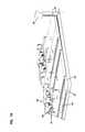
- FIG. 2is a perspective view of a work station of the fiber optic network of FIG. 1 ;
- FIG. 3is another view of the work station of the fiber optic network of FIG. 1 ;
- FIG. 4schematically shows portions of the fiber optic network of FIG. 1 ;
- FIG. 4Ais an enlarged view of a portion of the schematic diagram of FIG. 4 ;
- FIG. 4Bis an enlarged view of another portion of the schematic diagram of FIG. 4 ;
- FIG. 5is a perspective view showing multi-fiber connectors and an adapter for receiving such multi-fiber connectors, the multi-fiber connectors are shown in alignment with the adapter;
- FIG. 6shows the multi-fiber connectors of FIG. 5 inserted within the adapter of FIG. 5 ;
- FIG. 7shows a fiber optic harness that can be used in fiber optic networks in accordance with the principles of the present disclosure
- FIG. 8shows an alternative arrangement for the portion of the fiber optic network depicted at FIG. 4 ;
- FIG. 9shows another arrangement for a fiber optic network in accordance with the principles of the present disclosure.
- FIG. 10shows still another configuration for a fiber optic network in accordance with the principles of the present disclosure.
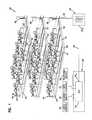
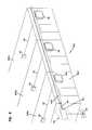
- FIGS. 1 , 1 A, 2 and 3show an in-building passive optical network 20 in accordance with the principles of the present disclosure.
- the optical network 20includes an in-building fiber management center 22 optically connected by a multi-fiber cable 23 (i.e., a cable having multiple optical fibers contained within a jacket) to an optical line terminal 24 (OLT) provided at a remote data center 26 .
- the multi-fiber cable 23has first and second opposite ends 23 1 , 23 2 .
- the optical line terminal 24interfaces with different types of telecommunication services such as video services 28 , internet services 30 , data services 32 and telephone services 34 .
- the optical network 20also includes a plurality of fiber distribution hubs 36 .
- the fiber distribution hubs 36are shown on separate floors of a building and are shown optically connected to the in-building fiber management center 22 by multi-fiber cables 38 .
- Multi-fiber cables 40are routed from the fiber distribution hubs 36 to a plurality of fiber distribution terminals 42 provided at each floor of the building.
- Fiber optic cables 44i.e., cables each having at least one optical fiber within a jacket
- Fiber optic cables 50are routed from the wall boxes 46 to desktop optical network terminals 52 (ONT) where optical signals carried through the optical network 20 are converted from optical to electrical signals.
- Computer cables 54connect the desktop optical network terminals 52 to computers 56 located at the desktop locations 48
- phone cables 58connect the desktop optical network terminals 52 to telephones 60 located at the desktop locations 48
- the desktop optical network terminals 52can also be connected to other components such as televisions.
- the desktop equipmente.g., phone, computer, television, etc.
- the fiber optic cables 50can be routed directly from the wall boxes 46 to the desktop equipment.
- the optical line terminal 24is shown located at a remote data center such as at a service provider central office or at an intermediate location between the central office and the building. It will be appreciated that in other embodiments, the optical line terminal 24 can be located at the in-building fiber management center 22 or elsewhere in the building. Additionally, the in-building fiber management center 22 can be in a data room or data closet. Alternatively, the in-building fiber management center 22 can constitute a telecommunications rack or frame within the building (e.g., in the basement), or a cabinet, wall box or other type of enclosure positioned within the building.
- spools for rapidly deploying fiber optic cablescan be incorporated into or on various housings, structures or other components of the system.
- rapid deployment spoolscan be incorporated into components (e.g., drawers, panels, cabinets, etc.) at the in-building fiber management center 22 , into the fiber distribution hubs 36 , into the fiber distribution terminals 42 and into the wall boxes 46 .
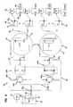
- FIGS. 4 , 4 A and 4 Bschematically show a portion of the in-building passive optical network 20 of FIG. 1 with deployment spools incorporated into various components of the network.
- the depicted fiber distribution terminals 42are shown including deployment spools 72 for facilitating paying out the multi-fiber cables 40 during deployment of the multi-fiber cables 40 from the fiber distribution terminals 42 to the fiber distribution hubs 36 .
- the wall boxes 46are depicted including deployment spools 74 for facilitating paying out the fiber optic cables 44 during deployment of the cables 44 from the wall boxes 46 to the fiber distribution terminals 42 .
- the in-building fiber management center 22is shown including a telecommunications rack or frame 79 on which a piece of telecommunications equipment 80 (e.g., drawer, panel, module or other component) is mounted.
- the piece of telecommunications equipment 80includes the spool 70 .
- the spool 70can be rotatably mounted to a structural component of the piece of telecommunications equipment 80 by a structure such as a spindle and bearing arrangement.
- the spool 70can be rotatably mounted on a structural component (e.g., a drawer framework) of the piece of equipment 80 such that the spool 70 can rotate about its central axis 82 relative to the structural component when the multi-fiber cable 38 wrapped about the spool 70 is paid off from the spool 70 .
- the depicted multi-fiber cable 38includes first and second ends 38 1 , 38 2 at which multi-fiber connectors 84 (i.e., fiber optic connectors having ferrules that each support the end portions of a plurality of optical fibers) are mounted.
- the depicted piece of equipment 80also includes multi-fiber connector adapter 86 (a fiber optic adapter adapted for coupling together two multi-fiber connectors, hereinafter referred to as an MFC adapter) mounted to the structural component.
- MFC adapter 86 of the equipment 80functions to couple multi-fiber connector 84 mounted at the first end 38 1 of the multi-fiber optic cable 38 to corresponding multi-fiber connector 84 mounted at the second end 23 2 of the multi-fiber cable 23 routed from the piece of equipment 80 to the optical line terminal 24 .
- multi-fiber connector 84 mounted at the second end 23 1 of the multi-fiber cable 23is inserted into a first end of MFC adapter 86 of the equipment 80 .
- Multi-fiber connector 84 mounted at the first end 38 1 of the fiber optic cable 38is initially secured to a portion of the deployment spool 70 at a location where the first end 38 1 of the fiber optic cable 38 does not interfere with paying out the second end 38 2 of the cable 38 from the spool 70 .
- the second end 38 2 of the cable 38is pulled toward the fiber distribution hub 36 .
- the spool 70spins about its axis 82 relative to the structural component of the equipment 80 thereby allowing the fiber optic cable 38 to be paid off from (i.e., dispensed from) the spool 70 .
- the installercontinues to dispense the cable 38 from the spool 70 until a sufficient length of cable has been dispensed such that multi-fiber connector 84 at the second end 38 2 of the cable 38 can be plugged into MFC adapter 86 located at a signal input location 300 of the fiber distribution hub 36 .
- Multi-fiber connector 84 at the first end 38 1is then uncoupled/detached from the deployment spool 70 and plugged into a second end of MFC adapter 86 of the equipment 80 to provide an optical connection between the multi-fiber cable 23 and the multi-fiber cable 38 .
- rack mounted drawershaving integrated spool dispensing capabilities are disclosed in U.S. Patent Application Ser. No. 61/227,247 entitled “Rapid Universal Rack Mount Drawer”, which is hereby incorporated by reference in its entirety.
- FIGS. 5 and 6illustrate an example configuration for first and second multi-fiber connectors 84 1 , 84 2 that can be used in systems in accordance with the principles of the present disclosure.
- the depicted multi-fiber connectors 84 1 , 84 2each include a ferrule 90 in which the end portions of a plurality of optical fibers 92 are secured.
- the fibers 92have end faces that are aligned along a line or lines defined across the length of the end surface of the ferrule 90 .
- the fiber optic connectors 84 1 , 84 2can include alignment structures provided on the ferrule for aligning the end faces of the fibers secured in the ferrule of a first multi-fiber connector with the end faces of the optical fiber secured within the ferrule of a second multi-fiber connector.
- the alignment structurescan include pins 85 provided on the multi-fiber connector 84 1 that fit within corresponding receptacles (not shown) defined within the ferrule 90 of the multi-fiber connector 84 2 .
- the multi-fiber connectors 84 1 , 84 2also include release sleeves 94 mounted over main housings 96 that support the ferrules 90 . The release sleeves 94 can be retracted relative to the main housings 96 to assist in releasing the multi-fiber connectors from a MFC adapter.
- the MFC adapter 86 of FIGS. 5 and 6is an example of the type of MFC adapter that can be used in systems in accordance with the principles of the present disclosure.
- the MFC adapter 86includes an adapter body 200 defining a first end 201 positioned opposite from a second end 202 .
- a passageextends longitudinally through the adapter body 200 between a first port 204 located at the first end 201 of the adapter body 200 and a second port 206 located at the second end 202 of the adapter body 200 .
- Latches 208 or other retention structuresare provided within the adapter body 200 .
- multi-fiber connectors 84 1 , 84 2When multi-fiber connectors 84 1 , 84 2 are respectively inserted within the first and second ports 204 , 206 of the adapter body 200 , the ferrules 90 of the multi-fiber connectors 84 1 , 84 2 abut one another with their respective fibers 92 in alignment with one another (e.g., via the pin and receptacle alignment structure described above), and the latches 208 provided within the adapter body 200 mechanically retain the multi-fiber connectors 84 1 , 84 2 within the adapter body 200 such that the multi-fiber connectors 84 1 , 84 2 are mechanically coupled together.
- the multi-fiber connectors 84 1 , 84 2can be disengaged from the latches 208 of the adapter 86 and removed from their corresponding ports 204 , 206 of the adapter body 200 .
- the depicted fiber distribution hub 36includes a cabinet 100 including various regions for mounting optical components.
- the cabinet 100can include the signal input location 300 , an output cable connection location 302 , a splitter module mounting location 304 , a connector storage location 306 and a termination region 308 .
- MFC adapters 86can be provided at the signal input location 300 and one or more MFC adapters 86 (e.g., 1-to-M MFC adapters) can also be provided at the output cable connection location 302 .
- a fiber optic harness 100 acan be used to provide an optical connection between the signal input location 300 and the splitter module mounting location 304 and a fiber optic harness 100 b can be used to provide an optical connection between the termination region 308 and the signal output location 302 .
- Splitter modules 102e.g., 1-to-N splitter modules
- Fiber optic splitter pigtails 107are used to carry the output signals from the splitter module mounting location 304 to the termination region 308 .
- the fiber optic harness 100 bthen carries the output signals from the termination region 308 to the output cable connection location 302 .
- Connectorized ends of at least some of the splitter pigtails 107can be temporarily stored at the connector storage location 306 when the splitter pigtails 107 are not needed at the termination region 308 for providing service connections to customers.
- An example fiber distribution hub having features as described aboveis disclosed by U.S. patent application Ser. No. 12/241,576 entitled “Low Profile Fiber Distribution Hub”, now U.S. Pat. No. 7,751,672, which is hereby incorporated by reference in its entirety.
- FIG. 7shows a harness 100 x having an example configuration that can be used for the harnesses 100 a , 100 b .
- the harness 100 xincludes a ribbon portion 400 including a plurality of ribbonized optical fibers.
- Multi-fiber connector 84is mounted at a first end 402 of the ribbon portion 400 with the optical fibers of the ribbon portion 400 being terminated at the multi-fiber connector 84 .
- a second end 404 of the ribbon portion 400is located at a fan-out 406 where the optical fibers of the ribbon portion 400 are separated from one another into individual pigtails 408 .
- Each of the pigtails 408can include an optical fiber, a buffer layer (e.g., a 900 micron buffer layer) surrounding the fiber, an outer jacket (e.g., a 2 millimeter outer jacket) and a strength layer (e.g., a layer of aramid yarn) positioned between the outer jacket and the buffer layer.
- the pigtails 408include free ends 410 at which single fiber connectors 412 (e.g., an SC connector or other connector including a ferrule supporting a single optical fiber) are mounted.
- the splitter mounting location 304 of the fiber distribution hub 36includes a panel, shelf, housing or other structure for supporting from 1-to-N of the splitter modules 102 .
- the splitter mounting location 304includes from 1-to-N single fiber connector (SFC) adapters 414 for use in optically connecting the splitter modules 102 to the pigtails 408 of the harness 100 a .
- the splitter modules 102can include outer housings 416 that each enclose one or more optical splitters for optically splitting the input signals from the harness 100 a into output signals that are outputted from the splitter module 102 via the splitter pigtails 107 .
- the optical splitterscan provide 1-to-X split ratios (e.g., 1-to-8; 1-to-16, 1-to-32).
- the splitter modules 102can include single fiber connectors 412 mounted to the outer housings 416 for use in inputting the input signals from the harness 100 a to the splitters 418 within the housings 416 .
- the connectors 412 of the splitter modules 102are coupled to the connectors 412 of the harness 100 a by the SFC adapters 414 of the splitter mounting location 304 .
- optical splitter modules 102can have a plug-in-play configuration.
- An example plug-in-play splitter module configurationis disclosed at U.S. Pat. No.
- the signal input location 300 of the fiber distribution hub 36provides an interface location for optically interconnecting the optical harness 100 a to the multi-fiber cable 38 .
- the MFC adapter 86 at the signal input location 300mechanically couples the multi-fiber connector 84 positioned at the second end 38 2 of the multi-fiber cable 38 to the multi-fiber connector 84 of the optical harness 100 a such that an optical connection exists between the cable 38 and the optical harness 100 a.
- the splitter pigtails 107can each include an optical fiber, a buffer layer (e.g., a loose or tight 900 micron buffer layer) surrounding the fiber, an outer jacket (e.g., a 2 millimeter outer jacket) and a strength layer (e.g., a layer of aramid yarn) positioned between the outer jacket and the buffer layer.
- the splitter pigtails 107include free ends 109 spaced-apart from the splitter module housings 416 .
- Single fiber connectors 412e.g., SC connectors or other connectors including a ferrule supporting a single optical fiber
- the termination region 308 of the fiber distribution hub 36includes a plurality of SFC adapters 414 mounted on an adapter support structure such as a panel or frame.
- the termination region 308functions to mechanically and optically connect the connectors 412 at the free ends 109 of the splitter pigtails 107 to the connectors 412 of the optical harnesses 100 b .
- the multi-fiber connectors 84 of the optical harnesses 100 bplug into MFC adapters 86 located at the output cable connection location 302 .
- the output cable connection location 302 of the fiber distribution hub 36provides an interface location for optically interconnecting the optical harnesses 100 b to the multi-fiber cables 40 . For example, as shown at FIG.
- the MFC adapters 86 at the output cable connection location 302mechanically couple multi-fiber connectors 84 positioned at first ends 40 1 of the multi-fiber cables 40 to the multi-fiber connectors 84 of the optical harnesses 100 b such that optical connections exist between the cables 40 and the optical harnesses 100 b .
- the multi-fiber cables 40have second ends 40 2 that are routed into the fiber distribution terminals 42 .
- the fiber distribution terminals 42 of the optical network 20each include an enclosure 140 in which a termination region 142 having a plurality of fiber optic SFC adapters 414 is housed.
- the deployment spools 72are shown mounted to the exterior of the enclosure 140 .
- the deployment spools 72may be housed within the enclosures 140 .
- the deployment spools 72are rotatable about rotation axes 144 . When the deployment spools 72 are rotated about the rotation axes 144 , the enclosures 140 and their corresponding termination regions 142 rotate in unison with the deployment spools 72 about the rotation axes 144 .
- Example fiber distribution terminalsare disclosed in U.S. patent application Ser. No. 12/113,786, filed May 1, 2008, now U.S. Pat. No. 7,715,679, U.S. patent application Ser. No. 12/182,705, filed Jul. 30, 2008, now U.S. Pat. No. 7,756,379, and U.S. patent application Ser. No. 12/199,923, filed Aug. 28, 2008, now U.S. Pat. No. 7,869,682, which are hereby incorporated by reference in their entireties.
- the multi-fiber distribution cables 40have first ends 40 1 positioned opposite from second ends 40 2 .
- the first ends 40 1 of the multi-fiber distribution cables 40include multi-fiber connectors 84 that are inserted into the MFC adapters 86 provided at the output cable connection location 302 of the fiber distribution hub(s) 36 to provide optical connections therein between.
- the second ends 40 2 of the multi-fiber fiber optic cables 40extend into the enclosures 140 and are broken out (i.e., fanned out) into individual upjacketed fibers 146 at fanouts 148 .
- Single fiber connectors 412are mounted at the ends of the individual upjacketed fibers 146 .
- the single fiber connectors 412are inserted into ports of the SFC adapters 414 provided at the termination region 142 .
- the multi-fiber cables 40Prior to installation, the multi-fiber cables 40 are wrapped around their corresponding deployment spools 72 to facilitate cable management during transport.
- the fiber distribution terminals 42are moved to their desired mounting locations and mounted in place (e.g., to a wall or other structure). Thereafter, the first ends 40 1 of the multi-fiber cables 40 are pulled away from the mounted fiber distribution terminals 42 thereby causing the enclosures 140 of the fiber distribution terminals 42 and their corresponding spools 72 to rotate about the rotation axes 144 as the multi-fiber cables 40 are paid off from the spools 72 .
- the first ends 40 1 of the multi-fiber cables 40are pulled until they reach their corresponding fiber distribution hubs 36 and are plugged into corresponding MFC adapters 86 at the output cable connection locations 302 of the fiber distribution hubs 36 . Since the termination regions 142 rotate in unison with the deployment spools 72 during deployment of the multi-fiber cables 40 , the single fiber connectors 412 at the second ends 40 2 of the multi-fiber distribution cables 40 can be plugged into the SFC adapters 414 of the termination region 142 as the cables 40 are paid off from the spools 72 during the installation process.
- the first ends 40 1 of the multi-fiber cables 40are initially inserted into the MFC adapters 86 at the output cable connection locations 302 of the fiber distribution hubs 36 with the fiber distribution terminals 42 in close proximity to the fiber distribution hubs 36 .
- the installermoves the fiber distribution terminals 42 away from the fiber distribution hubs 36 .
- the deployment spools 72spin thereby allowing the multi-fiber cables 40 to be paid off from the spools 72 . This process continues until the installer reaches the desired mounting location for the fiber distribution terminals 42 , at which time the fiber distribution terminals 42 are mounted at the desired mounting locations.
- the wall boxes 46 of the optical network 20each include an enclosure 160 to which one or more SFC adapters 414 are mounted.
- the deployment spools 74are mounted on or in the enclosures 160 .
- the deployment spools 74are rotatable relative to the enclosures 160 about rotation axes 162 to allow the fiber optic cables 44 to be dispensed or paid off from the spools 74 .
- the enclosures 160 and the spools 74rotate in unison about the rotation axes 162 to allow the fiber optic cables 44 to be paid off from the spools 74 .
- Example wall boxesare disclosed in U.S. patent application Ser. No. 12/472,905, filed May 27, 2009, now U.S. Patent Application Publication No. 2009/0294016, that is hereby incorporated by reference in its entirety.
- the fiber optic cables 44include first ends 44 1 that are connectorized with single fiber connectors 412 and second ends 44 2 that are also connectorized with single fiber connectors 412 .
- the single fiber connectors 412 at the first ends 44 1 of the cables 44are plugged into the termination regions 142 of the fiber distribution terminals 42 to optically connect the fiber optic cables 44 to the multi-fiber cables 40 .
- the single fiber fiber optic connectors 412 provided at the second ends 44 2 of the fiber optic cables 44are plugged into the SFC adapters 414 provided at the enclosures 160 of the wall boxes 46 .
- the patch cords 50are plugged into the SFC adapters 414 of the wall boxes 46 and are also plugged into the desktop optical network terminals 52 to provide an optical connection between the fiber optic cables 44 and the desktop optical network terminals 52 .
- the wall boxes 46can initially be mounted to walls adjacent to the desktop locations 48 . Thereafter, the first ends 44 1 of the fiber optic cables 44 can be pulled outwardly from the wall boxes 46 causing the deployment spools 74 to rotate about the rotation axes 162 . In the case where the deployment spools 74 rotate relative to the enclosure 160 , the single fiber connectors 412 at the second ends 44 2 of the fiber optic cables 44 can be disconnected from the SFC adapters 414 of the wall boxes 46 during deployment of the fiber optic cables 44 , and can be inserted into the SFC adapters 414 of the wall boxes 46 after deployment of the fiber optic cables 44 .
- the fiber optic cables 44are pulled away from the wall boxes 46 until sufficient length has been paid out to allow the single fiber connectors 412 at the first ends 44 1 of the fiber optic cables 44 to be plugged into the SFC adapters 414 at the termination regions 142 of the fiber distribution terminals 42 .
- the first ends 44 1 of the fiber optic cables 44are plugged into the SFC adapters 414 of the termination regions 142 at the fiber distribution terminals 42 while the wall boxes 46 are in close proximity to the fiber distribution terminals 42 .
- the installerthen moves the wall boxes 46 away from the fiber distribution terminals 42 .
- the deployment spools 72spin about their respective rotation axes 162 to allow the fiber optic cables 44 to be paid off from the deployment spools 74 . This process continues until the installer reaches the desktop locations 48 where the wall boxes 46 are to be mounted.
- FIG. 8shows an alternative in-building passive optical network 320 that is similar to the passive optical network 20 of FIG. 4 except an intermediate junction box 380 has been provided between the in-building fiber management center 22 and the fiber distribution hub 36 , and a deployment spool 76 has been provided at the fiber distribution hub 36 .
- the intermediate junction box 380includes an MFC adapter 86 that receives the multi-fiber connector 84 mounted at the second end 38 2 of the multi-fiber cable 38 routed from the in-building fiber management center 22 .
- An example fiber distribution hub including a deployment spoolis disclosed at U.S. Provisional Patent Application Ser. No. 61/245,082, filed Sep. 23, 2009, which is hereby incorporated by reference in its entirety.
- a multi-fiber cable 382is wrapped about the deployment spool 76 .
- the multi-fiber cable 382includes first and second ends 382 1 , 382 2 at which multi-fiber connectors 84 are mounted.
- the multi-fiber connector 84 at the first end 382 1 of the multi-fiber cable 382is plugged into the MFC adapter 86 located at the intermediate junction box 380 such that the multi-fiber cable 382 is optically connected to the multi-fiber cable 38 routed from the in-building cable management center 22 to the junction box 380 .
- the second end 382 2 of the multi-fiber cable 382is plugged into the MFC adapter 86 positioned at the signal input location 300 of the fiber distribution hub such that the multi-fiber cable 382 is optically connected to the fiber harness 100 a of the fiber distribution hub 36 .
- the deployment spool 76it is preferred for the deployment spool 76 to be rotatably mounted relative to the cabinet 100 of the fiber distribution hub 36 .
- the deployment spool 76can be mounted inside or outside the cabinet 100 .
- the deployment spool 76preferably rotates about a central axis 384 relative to the cabinet 100 as the multi-fiber cable 382 is paid off from the spool 76 .
- the multi-fiber connector 84 at the second end 382 2 of the multi-fiber cable 382is initially attached to the spool 76 such that the second end 382 2 is carried by the spool 76 as the second end 382 2 of the cable 382 is paid off from the spool.
- the spool 76spins about its axis 384 until a sufficient length of the cable 382 has been paid off to allow the multi-fiber connector 84 at the first end 382 1 of the cable 382 to be plugged into the MFC adapter 86 at the junction box 380 . Thereafter, the first end 382 1 of the cable 382 is detached from the spool 76 and plugged into the MFC adapter 86 located at the signal input location 300 of the fiber distribution hub 36 .
- the first end 382 1 of the cable 382can be routed all the way to the in-building fiber management center 22 and the first end 382 1 can be plugged into the MFC adapter 86 of the piece of equipment 80 such that the multi-fiber cable 382 is optically connected to the multi-fiber cable 23 routed from the OLT to the in-building fiber management center 22 .
- the multi-fiber cable 382eliminates the need for the junction box 380 and the multi-fiber cable 38 .
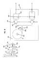
- FIG. 9illustrates another configuration for incorporating an optical network into a building.
- the configurationuses many of the same components described above and such components have been assigned the same reference numbers.
- the depicted buildingincludes a plurality of separate subscriber locations 600 a , 600 b and 600 c (e.g., apartments, offices, rooms, etc.).
- the subscriber locations 600 a - 600 care spaced along a hallway 602 of the building.
- the depicted portion of the networkincludes a fiber distribution terminal 42 as described above, which is preferably optically connected to a fiber distribution hub 36 .
- the fiber distribution terminal 42interfaces with a plurality of wall boxes 46 spaced apart along the length of the hall 602 . As shown in FIG.
- the wall boxes 46are mounted to a wall 603 of the hallway 602 at locations adjacent to doorways of the subscriber locations 600 a - 600 c .
- the fiber optic cables 44 corresponding to the wall boxes 46are routed from the wall boxes 46 to the fiber distribution terminal 42 through a track 604 that extends along the hallway 602 .
- First ends 44 1 of the cables 44are plugged into the termination region 142 of the fiber distribution terminal 42 .
- Second ends 44 2 of the cables 44are plugged into the SFC adapters 414 of the wall boxes 46 .
- Additional wall boxes 46are provided within each of the subscriber locations 600 a - 600 c .
- the wall boxes 46can be provided at desktop locations or elsewhere within the subscriber locations 600 a - 600 c .
- Cables 44 of the wall boxes 46 within the subscriber locations 600 a - 600 care routed to their corresponding wall boxes 46 located within the hallway 602 .
- the cables 44can be paid off from the spools 74 of the wall boxes 46 within the subscriber locations 600 a - 600 c and routed through the hallway wall 603 to reach the corresponding wall boxes 46 within the hallway 602 .
- the wall boxes 46 within the subscriber locations 600 a - 600 cprovide optical ports (e.g., adapter ports) for facilitating interconnecting with an ONT (e.g., a desktop ONT) or directly with a fiber optic compatible piece of equipment (e.g., a computer or phone with an optics card).
- ONTe.g., a desktop ONT
- fiber optic compatible piece of equipmente.g., a computer or phone with an optics card
- the hallway wall boxes 46can initially be installed along the length of the hallway 602 .
- the fiber optic cables 44 of the wall boxes 46 within the hallway 602can then be routed through the track 604 to the fiber distribution terminal 42 .
- the fiber optic cables 44are routed through the track 604 by pulling the first ends 44 1 of the cables 44 through the track 604 such that as the first ends 44 1 are pulled, the cables 44 are paid off from the spools 74 within the wall boxes 46 .
- the wall boxes 46can be mounted within the subscriber locations 600 a - 600 c , and the cables 44 can be paid off from the spools 74 of the wall boxes 46 and routed to the corresponding wall boxes 46 in the hallway 602 .
- the cables 44 of the wall boxes 46 within the subscriber locations 600 a - 600 care optically connected to the cables 44 of the wall boxes 46 in the hallway 602 by the SFC adapters 414 located within the wall boxes 46 mounted within the hallway 602 .
- FIG. 10shows an alternative configuration for an in-building passive optical network in accordance with the principles of the present disclosure.
- a bundle drop 700is routed from the fiber distribution terminal 42 through the wall 603 defining the hallway 602 .
- the bundle drop 700includes a plurality of optical fibers 702 optically connected to the termination region 142 of the distribution terminal 42 .
- the optical fibers 702are broken out at each of the subscriber locations 600 a - 600 c and are each connectorized with a single fiber connector 412 .
- the single fiber connectors 412can be inserted within SFC adapters 414 mounted within the wall 603 of the hallway 602 .
- Wall boxes 46are mounted within the subscriber locations 600 a - 600 c and cables 44 are routed from the wall boxes 46 to the SFC adapters 414 within the wall 603 . In this way, optical connections are made between the cables 44 and the fibers 702 of the bundle drop 700 .
- the cables 44are routed from the wall boxes 46 by pulling on the cables such that the internal spools 74 of the wall boxes 46 spin thereby allowing the cables 44 to be paid out from the wall boxes 46 and routed to the adapters 414 within the hallway wall 603 .
Landscapes
- Engineering & Computer Science (AREA)
- Civil Engineering (AREA)
- Structural Engineering (AREA)
- Physics & Mathematics (AREA)
- General Physics & Mathematics (AREA)
- Optics & Photonics (AREA)
- Light Guides In General And Applications Therefor (AREA)
- Mechanical Coupling Of Light Guides (AREA)
Abstract
Description
Claims (15)
Priority Applications (1)
| Application Number | Priority Date | Filing Date | Title |
|---|---|---|---|
| US12/953,781US8515234B2 (en) | 2009-11-25 | 2010-11-24 | Methods, systems and devices for providing fiber-to-the-desktop |
Applications Claiming Priority (2)
| Application Number | Priority Date | Filing Date | Title |
|---|---|---|---|
| US26447409P | 2009-11-25 | 2009-11-25 | |
| US12/953,781US8515234B2 (en) | 2009-11-25 | 2010-11-24 | Methods, systems and devices for providing fiber-to-the-desktop |
Publications (2)
| Publication Number | Publication Date |
|---|---|
| US20110158598A1 US20110158598A1 (en) | 2011-06-30 |
| US8515234B2true US8515234B2 (en) | 2013-08-20 |
Family
ID=44067213
Family Applications (1)
| Application Number | Title | Priority Date | Filing Date |
|---|---|---|---|
| US12/953,781Expired - Fee RelatedUS8515234B2 (en) | 2009-11-25 | 2010-11-24 | Methods, systems and devices for providing fiber-to-the-desktop |
Country Status (4)
| Country | Link |
|---|---|
| US (1) | US8515234B2 (en) |
| EP (1) | EP2504938A4 (en) |
| CN (1) | CN102668418A (en) |
| WO (1) | WO2011066364A2 (en) |
Cited By (1)
| Publication number | Priority date | Publication date | Assignee | Title |
|---|---|---|---|---|
| US9703063B2 (en) | 2012-11-07 | 2017-07-11 | CommScope Connectivity Belgium BVBA | Cable over-length storage system |
Families Citing this family (16)
| Publication number | Priority date | Publication date | Assignee | Title |
|---|---|---|---|---|
| US7715679B2 (en) | 2007-05-07 | 2010-05-11 | Adc Telecommunications, Inc. | Fiber optic enclosure with external cable spool |
| US7756379B2 (en) | 2007-08-06 | 2010-07-13 | Adc Telecommunications, Inc. | Fiber optic enclosure with internal cable spool |
| US8428419B2 (en)* | 2009-09-23 | 2013-04-23 | Adc Telecommunications, Inc. | Fiber distribution hub with internal cable spool |
| CN110174737A (en) | 2010-06-23 | 2019-08-27 | Adc电信公司 | Telecommunication assembly |
| WO2012054454A2 (en)* | 2010-10-19 | 2012-04-26 | Corning Cable Systems Llc | Transition box for multiple dwelling unit fiber optic distribution network |
| CA2877896C (en) | 2011-06-24 | 2020-07-21 | Adc Telecommunications, Inc. | Fiber termination enclosure with modular plate assemblies |
| EP2795811B1 (en)* | 2011-12-22 | 2018-08-22 | CommScope Technologies LLC | Fiber optic wall plate with redundancy system |
| US9348096B2 (en)* | 2012-03-30 | 2016-05-24 | Commscope Technologies Llc | Passive distribution system using fiber indexing |
| ES1141660Y (en) | 2012-12-19 | 2015-10-14 | Tyco Electronics Raychem Bvba | Distribution device with incrementally added dividers |
| MX2017004130A (en) | 2014-10-06 | 2017-10-31 | Adc Telecommunications Inc | Facilitating installation of fiber optic networks. |
| US9557498B2 (en) | 2014-12-19 | 2017-01-31 | Commscope Technologies Llc | Dust caps having coding system for facilitating installing a fiber optic network |
| CN109547108A (en)* | 2017-09-21 | 2019-03-29 | 中兴通讯股份有限公司 | ONT Optical Network Terminal and system |
| US11652337B2 (en)* | 2019-05-10 | 2023-05-16 | Meta Platforms, Inc. | Systems and methods for installing fiber optic cable onto a powerline conductor |
| US11353672B1 (en) | 2019-11-27 | 2022-06-07 | Meta Platforms, Inc. | Components for fiber optic cable installation on a powerline conductor |
| CN214101388U (en)* | 2020-08-20 | 2021-08-31 | 华为技术有限公司 | A spectroscopic device and spectroscopic system |
| US11962343B1 (en)* | 2023-09-29 | 2024-04-16 | Frontier Communications Holdings, Llc | Method for identifying and highlighting available fibers in a fiber distribution hub |
Citations (19)
| Publication number | Priority date | Publication date | Assignee | Title |
|---|---|---|---|---|
| US5317663A (en) | 1993-05-20 | 1994-05-31 | Adc Telecommunications, Inc. | One-piece SC adapter |
| US6457874B1 (en) | 2000-08-31 | 2002-10-01 | Corning Cable Systems Llc | Wall mountable mixed media outlet |
| US20080069511A1 (en) | 2004-01-27 | 2008-03-20 | Blackwell Chois A Jr | Multi-port optical connection terminal |
| US7349616B1 (en) | 2007-01-12 | 2008-03-25 | Corning Cable Systems Llc | Fiber optic local convergence points for multiple dwelling units |
| US20080080826A1 (en) | 2006-10-02 | 2008-04-03 | Eduardo Leon | Distribution module for an optic fiber distribution hub |
| US20080170824A1 (en)* | 2007-01-13 | 2008-07-17 | Furukawa Electric North America, Inc. | Fiber optic cabling for multi-dwelling unit (MDU) and commercial building deployments |
| US7409138B1 (en) | 2007-03-12 | 2008-08-05 | Corning Cable Systems Llc | Fiber optic local convergence points for multiple dwelling units |
| US7418181B2 (en) | 2006-02-13 | 2008-08-26 | Adc Telecommunications, Inc. | Fiber optic splitter module |
| US20080292261A1 (en) | 2007-05-07 | 2008-11-27 | Kowalczyk Scott C | Fiber optic enclosure with external cable spool |
| US20090074370A1 (en) | 2007-08-06 | 2009-03-19 | Adc Telecommunications, Inc. | Fiber optic enclosure with internal cable spool |
| US20090294016A1 (en)* | 2008-05-27 | 2009-12-03 | Derek Sayres | Flexible extruded cable molding system, methods, and tools |
| US20090317047A1 (en)* | 2008-06-19 | 2009-12-24 | Adc Telecommunications, Inc. | Methods and systems for distributing fiber optic telecommunications services to local area |
| US20100166376A1 (en)* | 2008-12-31 | 2010-07-01 | Nair K R Suresh | System for an internal rotating storage spool combined with top and bottom cable access in a fiber distribution terminal |
| US7751672B2 (en) | 2007-10-31 | 2010-07-06 | Adc Telecommunications, Inc. | Low profile fiber distribution hub |
| US7869682B2 (en) | 2007-09-05 | 2011-01-11 | Adc Telecommunications, Inc. | Fiber optic enclosure with tear-away spool |
| US20110030190A1 (en)* | 2009-08-06 | 2011-02-10 | 3M Innovative Properties Company | System and method for providing final drop in a living unit in a building |
| US20110044599A1 (en) | 2009-07-21 | 2011-02-24 | Adc Telecommunications, Inc. | Rapid universal rack mount enclosure |
| US20110103761A1 (en)* | 2009-09-23 | 2011-05-05 | Adc Telecommunications, Inc. | Fiber Distribution Hub with Internal Cable Spool |
| US20120093473A1 (en)* | 2010-10-19 | 2012-04-19 | Terry Dean Cox | Transition box for multiple dwelling unit fiber optic distribution network |
Family Cites Families (7)
| Publication number | Priority date | Publication date | Assignee | Title |
|---|---|---|---|---|
| SE513869C2 (en)* | 1999-03-11 | 2000-11-20 | Ericsson Telefon Ab L M | Method and apparatus for installing optical fibers |
| US6349893B1 (en)* | 2000-02-01 | 2002-02-26 | Avaya Technology Corp. | Retractable fiber slack storage device |
| JP3815479B2 (en)* | 2004-02-20 | 2006-08-30 | 松下電工株式会社 | Optical fiber wiring equipment |
| US7400814B1 (en)* | 2007-01-13 | 2008-07-15 | Furukawa Electric North America, Inc. | Wall-mountable optical fiber and cable management apparatus |
| US7748660B2 (en)* | 2007-06-22 | 2010-07-06 | Ofs Fitel, Llc | Fiber optic rapid spooling tool |
| FR2922032B1 (en)* | 2007-10-04 | 2011-06-17 | Nexans | OPTICAL OUTLET FOR TELECOMMUNICATION NETWORK. |
| CN101408874A (en)* | 2007-10-09 | 2009-04-15 | 深圳富泰宏精密工业有限公司 | Apparatus and method for translating image and character |
- 2010
- 2010-11-24USUS12/953,781patent/US8515234B2/ennot_activeExpired - Fee Related
- 2010-11-24EPEP10833904.5Apatent/EP2504938A4/ennot_activeCeased
- 2010-11-24WOPCT/US2010/057973patent/WO2011066364A2/enactiveApplication Filing
- 2010-11-24CNCN2010800585161Apatent/CN102668418A/enactivePending
Patent Citations (20)
| Publication number | Priority date | Publication date | Assignee | Title |
|---|---|---|---|---|
| US5317663A (en) | 1993-05-20 | 1994-05-31 | Adc Telecommunications, Inc. | One-piece SC adapter |
| US6457874B1 (en) | 2000-08-31 | 2002-10-01 | Corning Cable Systems Llc | Wall mountable mixed media outlet |
| US20080069511A1 (en) | 2004-01-27 | 2008-03-20 | Blackwell Chois A Jr | Multi-port optical connection terminal |
| US7418181B2 (en) | 2006-02-13 | 2008-08-26 | Adc Telecommunications, Inc. | Fiber optic splitter module |
| US20080080826A1 (en) | 2006-10-02 | 2008-04-03 | Eduardo Leon | Distribution module for an optic fiber distribution hub |
| US7349616B1 (en) | 2007-01-12 | 2008-03-25 | Corning Cable Systems Llc | Fiber optic local convergence points for multiple dwelling units |
| US7548680B2 (en) | 2007-01-12 | 2009-06-16 | Corning Cable Systems Llc | Fiber optic local convergence points for multiple dwelling units |
| US20080170824A1 (en)* | 2007-01-13 | 2008-07-17 | Furukawa Electric North America, Inc. | Fiber optic cabling for multi-dwelling unit (MDU) and commercial building deployments |
| US7409138B1 (en) | 2007-03-12 | 2008-08-05 | Corning Cable Systems Llc | Fiber optic local convergence points for multiple dwelling units |
| US20080292261A1 (en) | 2007-05-07 | 2008-11-27 | Kowalczyk Scott C | Fiber optic enclosure with external cable spool |
| US20090074370A1 (en) | 2007-08-06 | 2009-03-19 | Adc Telecommunications, Inc. | Fiber optic enclosure with internal cable spool |
| US7869682B2 (en) | 2007-09-05 | 2011-01-11 | Adc Telecommunications, Inc. | Fiber optic enclosure with tear-away spool |
| US7751672B2 (en) | 2007-10-31 | 2010-07-06 | Adc Telecommunications, Inc. | Low profile fiber distribution hub |
| US20090294016A1 (en)* | 2008-05-27 | 2009-12-03 | Derek Sayres | Flexible extruded cable molding system, methods, and tools |
| US20090317047A1 (en)* | 2008-06-19 | 2009-12-24 | Adc Telecommunications, Inc. | Methods and systems for distributing fiber optic telecommunications services to local area |
| US20100166376A1 (en)* | 2008-12-31 | 2010-07-01 | Nair K R Suresh | System for an internal rotating storage spool combined with top and bottom cable access in a fiber distribution terminal |
| US20110044599A1 (en) | 2009-07-21 | 2011-02-24 | Adc Telecommunications, Inc. | Rapid universal rack mount enclosure |
| US20110030190A1 (en)* | 2009-08-06 | 2011-02-10 | 3M Innovative Properties Company | System and method for providing final drop in a living unit in a building |
| US20110103761A1 (en)* | 2009-09-23 | 2011-05-05 | Adc Telecommunications, Inc. | Fiber Distribution Hub with Internal Cable Spool |
| US20120093473A1 (en)* | 2010-10-19 | 2012-04-19 | Terry Dean Cox | Transition box for multiple dwelling unit fiber optic distribution network |
Non-Patent Citations (21)
| Title |
|---|
| "Crossroads-Opts for a Fiber-to-the-Desk Solution," Siemon, (2009). |
| "Media Conversion-Myths about Media Converters," ADC (2004). |
| "OmniReach® FTTX Solutions-MDU Rapid Fiber System" ADC (2009). |
| "TrueNet® Fiber Plug-and-Play Solutions for Data Center Applications Engineered for Uptime (TM)" ADC (2008). |
| "TrueNet® Fiber Plug-and-Play Solutions for Data Center Applications Engineered for Uptime ™" ADC (2008). |
| "Verizon FiOS Tech Heading to Enterprises" (May 30, 2008), 5 pp. |
| http://en.wikipedia.org/wiki/Passive-optical-network, Passive Optical Network (printed Apr. 6, 2009). |
| http://lw.pennnet.com/articles/article-display.cfm?article-id=33907 "Ethernet Interoperability brings fiber to the desk," Total Assessment of Next-Gen Networks (printed Mar. 13, 2009). |
| http://www.alibaba.com/product-gs/201158613/Fiber-to-the-Desk-Solution13 FTTD/sho . . . "FTTH Triple Play Acess Solution," Alibaba.com, (printed Mar. 13, 2009). |
| http://www.alliedtelesyn.com/solutions/diagram.aspx?29, "Fiber to the Desk" Allied Telesis (2009). |
| http://www.doc.ic.ac.uk/~nd/surprise-97/journal/vol4/sm27/war.html, "3. The War between Copper and Fibre Optics: Fiber-To-The-Desk," (printed Mar. 13, 2009). |
| http://www.doc.ic.ac.uk/˜nd/surprise—97/journal/vol4/sm27/war.html, "3. The War between Copper and Fibre Optics: Fiber-To-The-Desk," (printed Mar. 13, 2009). |
| http://www.iec.org/online/tutorials/tdma/index.asp, Time Division Multiple Access (TDMA), International Engineering Consortium, (printed Apr. 7, 2009). |
| http://www.imcnetworks.com/FTTD.cfm, Fiber to the Desk Solutions by IMC Networks (2009). |
| International Search Report and Written Opinion mailed Jun. 20, 2011. |
| Mathas, "Breaking fiber-to-the-desk barriers," Premises Networks, (2002). |
| Pearson, "Fiber is Magic: It makes Wiring Closets Disappear!" The Fiber Optic Association-Tech Topics, (2002). |
| Sharma, "Brain Power- Fiber-to-the-Desk Cabling Paves the Way for a Data Explosion in Medical Imaging," Fiber Optics (2001). |
| Shepard, "Characteristics of Switches and Routers," Juniper Networks, (2006), pp. 1-22. |
| Stagg et al. "FTTD (Fiber to the Desk)" Lafayette Pro Fiber (2008). |
| White Papers-"Two-Inch Cable Bend Radius: A New Standard for Wire and Cable Management Systems," (2009). |
Cited By (1)
| Publication number | Priority date | Publication date | Assignee | Title |
|---|---|---|---|---|
| US9703063B2 (en) | 2012-11-07 | 2017-07-11 | CommScope Connectivity Belgium BVBA | Cable over-length storage system |
Also Published As
| Publication number | Publication date |
|---|---|
| US20110158598A1 (en) | 2011-06-30 |
| WO2011066364A3 (en) | 2011-10-06 |
| EP2504938A2 (en) | 2012-10-03 |
| EP2504938A4 (en) | 2017-05-17 |
| WO2011066364A2 (en) | 2011-06-03 |
| CN102668418A (en) | 2012-09-12 |
Similar Documents
| Publication | Publication Date | Title |
|---|---|---|
| US8515234B2 (en) | Methods, systems and devices for providing fiber-to-the-desktop | |
| US12149288B2 (en) | Methods, systems, and devices for integrating wireless technology into a fiber optic network | |
| US11513303B2 (en) | Optical fiber distribution systems and components | |
| US10830965B2 (en) | Architecture for a fiber optic network | |
| US10606006B2 (en) | Optical fiber distribution systems and components | |
| CN103430072B (en) | For the transformation box in the fiber distribution network of multitenant unit | |
| US9684142B2 (en) | Rapid distribution terminal | |
| US10495834B2 (en) | Optical fiber management | |
| US20200310066A1 (en) | Fiber optic network architecture using high fiber-count fiber optic connectors | |
| US20250164727A1 (en) | Consolidation terminals | |
| EP3825746A1 (en) | Toolless splitter and splice tray assemblies and systems |
Legal Events
| Date | Code | Title | Description |
|---|---|---|---|
| AS | Assignment | Owner name:ADC TELECOMMUNICATIONS, INC., MINNESOTA Free format text:ASSIGNMENT OF ASSIGNORS INTEREST;ASSIGNORS:LEBLANC, THOMAS G.;SMITH, TREVOR D.;MARCOUILLER, THOMAS;AND OTHERS;SIGNING DATES FROM 20110103 TO 20110218;REEL/FRAME:025962/0275 | |
| STCF | Information on status: patent grant | Free format text:PATENTED CASE | |
| AS | Assignment | Owner name:TYCO ELECTRONICS SERVICES GMBH, SWITZERLAND Free format text:ASSIGNMENT OF ASSIGNORS INTEREST;ASSIGNOR:ADC TELECOMMUNICATIONS, INC.;REEL/FRAME:036060/0174 Effective date:20110930 | |
| AS | Assignment | Owner name:COMMSCOPE EMEA LIMITED, IRELAND Free format text:ASSIGNMENT OF ASSIGNORS INTEREST;ASSIGNOR:TYCO ELECTRONICS SERVICES GMBH;REEL/FRAME:036956/0001 Effective date:20150828 | |
| AS | Assignment | Owner name:COMMSCOPE TECHNOLOGIES LLC, NORTH CAROLINA Free format text:ASSIGNMENT OF ASSIGNORS INTEREST;ASSIGNOR:COMMSCOPE EMEA LIMITED;REEL/FRAME:037012/0001 Effective date:20150828 | |
| AS | Assignment | Owner name:JPMORGAN CHASE BANK, N.A., AS COLLATERAL AGENT, ILLINOIS Free format text:PATENT SECURITY AGREEMENT (TERM);ASSIGNOR:COMMSCOPE TECHNOLOGIES LLC;REEL/FRAME:037513/0709 Effective date:20151220 Owner name:JPMORGAN CHASE BANK, N.A., AS COLLATERAL AGENT, ILLINOIS Free format text:PATENT SECURITY AGREEMENT (ABL);ASSIGNOR:COMMSCOPE TECHNOLOGIES LLC;REEL/FRAME:037514/0196 Effective date:20151220 Owner name:JPMORGAN CHASE BANK, N.A., AS COLLATERAL AGENT, IL Free format text:PATENT SECURITY AGREEMENT (ABL);ASSIGNOR:COMMSCOPE TECHNOLOGIES LLC;REEL/FRAME:037514/0196 Effective date:20151220 Owner name:JPMORGAN CHASE BANK, N.A., AS COLLATERAL AGENT, IL Free format text:PATENT SECURITY AGREEMENT (TERM);ASSIGNOR:COMMSCOPE TECHNOLOGIES LLC;REEL/FRAME:037513/0709 Effective date:20151220 | |
| FPAY | Fee payment | Year of fee payment:4 | |
| CC | Certificate of correction | ||
| AS | Assignment | Owner name:REDWOOD SYSTEMS, INC., NORTH CAROLINA Free format text:RELEASE BY SECURED PARTY;ASSIGNOR:JPMORGAN CHASE BANK, N.A.;REEL/FRAME:048840/0001 Effective date:20190404 Owner name:ALLEN TELECOM LLC, ILLINOIS Free format text:RELEASE BY SECURED PARTY;ASSIGNOR:JPMORGAN CHASE BANK, N.A.;REEL/FRAME:048840/0001 Effective date:20190404 Owner name:ANDREW LLC, NORTH CAROLINA Free format text:RELEASE BY SECURED PARTY;ASSIGNOR:JPMORGAN CHASE BANK, N.A.;REEL/FRAME:048840/0001 Effective date:20190404 Owner name:COMMSCOPE TECHNOLOGIES LLC, NORTH CAROLINA Free format text:RELEASE BY SECURED PARTY;ASSIGNOR:JPMORGAN CHASE BANK, N.A.;REEL/FRAME:048840/0001 Effective date:20190404 Owner name:COMMSCOPE, INC. OF NORTH CAROLINA, NORTH CAROLINA Free format text:RELEASE BY SECURED PARTY;ASSIGNOR:JPMORGAN CHASE BANK, N.A.;REEL/FRAME:048840/0001 Effective date:20190404 Owner name:ALLEN TELECOM LLC, ILLINOIS Free format text:RELEASE BY SECURED PARTY;ASSIGNOR:JPMORGAN CHASE BANK, N.A.;REEL/FRAME:049260/0001 Effective date:20190404 Owner name:REDWOOD SYSTEMS, INC., NORTH CAROLINA Free format text:RELEASE BY SECURED PARTY;ASSIGNOR:JPMORGAN CHASE BANK, N.A.;REEL/FRAME:049260/0001 Effective date:20190404 Owner name:ANDREW LLC, NORTH CAROLINA Free format text:RELEASE BY SECURED PARTY;ASSIGNOR:JPMORGAN CHASE BANK, N.A.;REEL/FRAME:049260/0001 Effective date:20190404 Owner name:COMMSCOPE, INC. OF NORTH CAROLINA, NORTH CAROLINA Free format text:RELEASE BY SECURED PARTY;ASSIGNOR:JPMORGAN CHASE BANK, N.A.;REEL/FRAME:049260/0001 Effective date:20190404 Owner name:COMMSCOPE TECHNOLOGIES LLC, NORTH CAROLINA Free format text:RELEASE BY SECURED PARTY;ASSIGNOR:JPMORGAN CHASE BANK, N.A.;REEL/FRAME:049260/0001 Effective date:20190404 | |
| AS | Assignment | Owner name:JPMORGAN CHASE BANK, N.A., NEW YORK Free format text:ABL SECURITY AGREEMENT;ASSIGNORS:COMMSCOPE, INC. OF NORTH CAROLINA;COMMSCOPE TECHNOLOGIES LLC;ARRIS ENTERPRISES LLC;AND OTHERS;REEL/FRAME:049892/0396 Effective date:20190404 Owner name:WILMINGTON TRUST, NATIONAL ASSOCIATION, AS COLLATE Free format text:PATENT SECURITY AGREEMENT;ASSIGNOR:COMMSCOPE TECHNOLOGIES LLC;REEL/FRAME:049892/0051 Effective date:20190404 Owner name:JPMORGAN CHASE BANK, N.A., NEW YORK Free format text:TERM LOAN SECURITY AGREEMENT;ASSIGNORS:COMMSCOPE, INC. OF NORTH CAROLINA;COMMSCOPE TECHNOLOGIES LLC;ARRIS ENTERPRISES LLC;AND OTHERS;REEL/FRAME:049905/0504 Effective date:20190404 Owner name:WILMINGTON TRUST, NATIONAL ASSOCIATION, AS COLLATERAL AGENT, CONNECTICUT Free format text:PATENT SECURITY AGREEMENT;ASSIGNOR:COMMSCOPE TECHNOLOGIES LLC;REEL/FRAME:049892/0051 Effective date:20190404 | |
| FEPP | Fee payment procedure | Free format text:MAINTENANCE FEE REMINDER MAILED (ORIGINAL EVENT CODE: REM.); ENTITY STATUS OF PATENT OWNER: LARGE ENTITY | |
| FEPP | Fee payment procedure | Free format text:7.5 YR SURCHARGE - LATE PMT W/IN 6 MO, LARGE ENTITY (ORIGINAL EVENT CODE: M1555); ENTITY STATUS OF PATENT OWNER: LARGE ENTITY | |
| MAFP | Maintenance fee payment | Free format text:PAYMENT OF MAINTENANCE FEE, 8TH YEAR, LARGE ENTITY (ORIGINAL EVENT CODE: M1552); ENTITY STATUS OF PATENT OWNER: LARGE ENTITY Year of fee payment:8 | |
| AS | Assignment | Owner name:WILMINGTON TRUST, DELAWARE Free format text:SECURITY INTEREST;ASSIGNORS:ARRIS SOLUTIONS, INC.;ARRIS ENTERPRISES LLC;COMMSCOPE TECHNOLOGIES LLC;AND OTHERS;REEL/FRAME:060752/0001 Effective date:20211115 | |
| AS | Assignment | Owner name:COMMSCOPE, INC. OF NORTH CAROLINA, NORTH CAROLINA Free format text:PARTIAL RELEASE OF ABL SECURITY INTEREST;ASSIGNOR:JPMORGAN CHASE BANK, N.A.;REEL/FRAME:060649/0305 Effective date:20220712 Owner name:ARRIS ENTERPRISES LLC, NORTH CAROLINA Free format text:PARTIAL RELEASE OF ABL SECURITY INTEREST;ASSIGNOR:JPMORGAN CHASE BANK, N.A.;REEL/FRAME:060649/0305 Effective date:20220712 Owner name:COMMSCOPE TECHNOLOGIES LLC, NORTH CAROLINA Free format text:PARTIAL RELEASE OF ABL SECURITY INTEREST;ASSIGNOR:JPMORGAN CHASE BANK, N.A.;REEL/FRAME:060649/0305 Effective date:20220712 Owner name:COMMSCOPE, INC. OF NORTH CAROLINA, NORTH CAROLINA Free format text:PARTIAL RELEASE OF TERM LOAN SECURITY INTEREST;ASSIGNOR:JPMORGAN CHASE BANK, N.A.;REEL/FRAME:060649/0286 Effective date:20220712 Owner name:ARRIS ENTERPRISES LLC, NORTH CAROLINA Free format text:PARTIAL RELEASE OF TERM LOAN SECURITY INTEREST;ASSIGNOR:JPMORGAN CHASE BANK, N.A.;REEL/FRAME:060649/0286 Effective date:20220712 Owner name:COMMSCOPE TECHNOLOGIES LLC, NORTH CAROLINA Free format text:PARTIAL RELEASE OF TERM LOAN SECURITY INTEREST;ASSIGNOR:JPMORGAN CHASE BANK, N.A.;REEL/FRAME:060649/0286 Effective date:20220712 Owner name:BISON PATENT LICENSING, LLC, GEORGIA Free format text:ASSIGNMENT OF ASSIGNORS INTEREST;ASSIGNOR:COMMSCOPE TECHNOLOGIES LLC;REEL/FRAME:060641/0312 Effective date:20220628 | |
| AS | Assignment | Owner name:COMMSCOPE, INC. OF NORTH CAROLINA, NORTH CAROLINA Free format text:PARTIAL TERMINATION AND RELEASE OF SECURITY INTEREST IN PATENTS;ASSIGNOR:WILMINGTON TRUST, NATIONAL ASSOCIATION, AS COLLATERAL AGENT;REEL/FRAME:060671/0324 Effective date:20220711 Owner name:ARRIS ENTERPRISES LLC, PENNSYLVANIA Free format text:PARTIAL TERMINATION AND RELEASE OF SECURITY INTEREST IN PATENTS;ASSIGNOR:WILMINGTON TRUST, NATIONAL ASSOCIATION, AS COLLATERAL AGENT;REEL/FRAME:060671/0324 Effective date:20220711 Owner name:COMMSCOPE TECHNOLOGIES LLC, NORTH CAROLINA Free format text:PARTIAL TERMINATION AND RELEASE OF SECURITY INTEREST IN PATENTS;ASSIGNOR:WILMINGTON TRUST, NATIONAL ASSOCIATION, AS COLLATERAL AGENT;REEL/FRAME:060671/0324 Effective date:20220711 | |
| AS | Assignment | Owner name:ARRIS ENTERPRISES LLC, GEORGIA Free format text:RELEASE BY SECURED PARTY;ASSIGNOR:WILMINGTON TRUST, NATIONAL ASSOCIATION;REEL/FRAME:063270/0220 Effective date:20221116 Owner name:COMMSCOPE, INC. OF NORTH CAROLINA, NORTH CAROLINA Free format text:RELEASE BY SECURED PARTY;ASSIGNOR:WILMINGTON TRUST, NATIONAL ASSOCIATION;REEL/FRAME:063270/0220 Effective date:20221116 Owner name:COMMSCOPE TECHNOLOGIES LLC, NORTH CAROLINA Free format text:RELEASE BY SECURED PARTY;ASSIGNOR:WILMINGTON TRUST, NATIONAL ASSOCIATION;REEL/FRAME:063270/0220 Effective date:20221116 | |
| AS | Assignment | Owner name:ARRIS ENTERPRISES LLC, GEORGIA Free format text:PARTIAL TERMINATION AND RELEASE OF SECURITY INTEREST IN PATENTS RECORDED AT R/F 060752/0001;ASSIGNOR:WILMINGTON TRUST;REEL/FRAME:063322/0209 Effective date:20221116 Owner name:COMMSCOPE, INC. OF NORTH CAROLINA, NORTH CAROLINA Free format text:PARTIAL TERMINATION AND RELEASE OF SECURITY INTEREST IN PATENTS RECORDED AT R/F 060752/0001;ASSIGNOR:WILMINGTON TRUST;REEL/FRAME:063322/0209 Effective date:20221116 Owner name:COMMSCOPE TECHNOLOGIES LLC, NORTH CAROLINA Free format text:PARTIAL TERMINATION AND RELEASE OF SECURITY INTEREST IN PATENTS RECORDED AT R/F 060752/0001;ASSIGNOR:WILMINGTON TRUST;REEL/FRAME:063322/0209 Effective date:20221116 | |
| AS | Assignment | Owner name:RUCKUS WIRELESS, LLC (F/K/A RUCKUS WIRELESS, INC.), NORTH CAROLINA Free format text:RELEASE OF SECURITY INTEREST AT REEL/FRAME 049905/0504;ASSIGNOR:JPMORGAN CHASE BANK, N.A., AS COLLATERAL AGENT;REEL/FRAME:071477/0255 Effective date:20241217 Owner name:COMMSCOPE TECHNOLOGIES LLC, NORTH CAROLINA Free format text:RELEASE OF SECURITY INTEREST AT REEL/FRAME 049905/0504;ASSIGNOR:JPMORGAN CHASE BANK, N.A., AS COLLATERAL AGENT;REEL/FRAME:071477/0255 Effective date:20241217 Owner name:COMMSCOPE, INC. OF NORTH CAROLINA, NORTH CAROLINA Free format text:RELEASE OF SECURITY INTEREST AT REEL/FRAME 049905/0504;ASSIGNOR:JPMORGAN CHASE BANK, N.A., AS COLLATERAL AGENT;REEL/FRAME:071477/0255 Effective date:20241217 Owner name:ARRIS SOLUTIONS, INC., NORTH CAROLINA Free format text:RELEASE OF SECURITY INTEREST AT REEL/FRAME 049905/0504;ASSIGNOR:JPMORGAN CHASE BANK, N.A., AS COLLATERAL AGENT;REEL/FRAME:071477/0255 Effective date:20241217 Owner name:ARRIS TECHNOLOGY, INC., NORTH CAROLINA Free format text:RELEASE OF SECURITY INTEREST AT REEL/FRAME 049905/0504;ASSIGNOR:JPMORGAN CHASE BANK, N.A., AS COLLATERAL AGENT;REEL/FRAME:071477/0255 Effective date:20241217 Owner name:ARRIS ENTERPRISES LLC (F/K/A ARRIS ENTERPRISES, INC.), NORTH CAROLINA Free format text:RELEASE OF SECURITY INTEREST AT REEL/FRAME 049905/0504;ASSIGNOR:JPMORGAN CHASE BANK, N.A., AS COLLATERAL AGENT;REEL/FRAME:071477/0255 Effective date:20241217 | |
| FEPP | Fee payment procedure | Free format text:MAINTENANCE FEE REMINDER MAILED (ORIGINAL EVENT CODE: REM.); ENTITY STATUS OF PATENT OWNER: LARGE ENTITY | |
| LAPS | Lapse for failure to pay maintenance fees | Free format text:PATENT EXPIRED FOR FAILURE TO PAY MAINTENANCE FEES (ORIGINAL EVENT CODE: EXP.); ENTITY STATUS OF PATENT OWNER: LARGE ENTITY | |
| STCH | Information on status: patent discontinuation | Free format text:PATENT EXPIRED DUE TO NONPAYMENT OF MAINTENANCE FEES UNDER 37 CFR 1.362 |