US8513514B2 - Solar tracking for terrestrial solar arrays with variable start and stop positions - Google Patents
Solar tracking for terrestrial solar arrays with variable start and stop positionsDownload PDFInfo
- Publication number
- US8513514B2 US8513514B2US12/498,135US49813509AUS8513514B2US 8513514 B2US8513514 B2US 8513514B2US 49813509 AUS49813509 AUS 49813509AUS 8513514 B2US8513514 B2US 8513514B2
- Authority
- US
- United States
- Prior art keywords
- solar cell
- cell array
- time
- sun
- tracking
- Prior art date
- Legal status (The legal status is an assumption and is not a legal conclusion. Google has not performed a legal analysis and makes no representation as to the accuracy of the status listed.)
- Expired - Fee Related, expires
Links
Images


Classifications
- F—MECHANICAL ENGINEERING; LIGHTING; HEATING; WEAPONS; BLASTING
- F24—HEATING; RANGES; VENTILATING
- F24S—SOLAR HEAT COLLECTORS; SOLAR HEAT SYSTEMS
- F24S40/00—Safety or protection arrangements of solar heat collectors; Preventing malfunction of solar heat collectors
- F—MECHANICAL ENGINEERING; LIGHTING; HEATING; WEAPONS; BLASTING
- F24—HEATING; RANGES; VENTILATING
- F24S—SOLAR HEAT COLLECTORS; SOLAR HEAT SYSTEMS
- F24S30/00—Arrangements for moving or orienting solar heat collector modules
- F24S30/40—Arrangements for moving or orienting solar heat collector modules for rotary movement
- F24S30/45—Arrangements for moving or orienting solar heat collector modules for rotary movement with two rotation axes
- F24S30/452—Vertical primary axis
- F—MECHANICAL ENGINEERING; LIGHTING; HEATING; WEAPONS; BLASTING
- F24—HEATING; RANGES; VENTILATING
- F24S—SOLAR HEAT COLLECTORS; SOLAR HEAT SYSTEMS
- F24S50/00—Arrangements for controlling solar heat collectors
- F24S50/20—Arrangements for controlling solar heat collectors for tracking
- H—ELECTRICITY
- H02—GENERATION; CONVERSION OR DISTRIBUTION OF ELECTRIC POWER
- H02S—GENERATION OF ELECTRIC POWER BY CONVERSION OF INFRARED RADIATION, VISIBLE LIGHT OR ULTRAVIOLET LIGHT, e.g. USING PHOTOVOLTAIC [PV] MODULES
- H02S20/00—Supporting structures for PV modules
- H02S20/10—Supporting structures directly fixed to the ground
- H—ELECTRICITY
- H02—GENERATION; CONVERSION OR DISTRIBUTION OF ELECTRIC POWER
- H02S—GENERATION OF ELECTRIC POWER BY CONVERSION OF INFRARED RADIATION, VISIBLE LIGHT OR ULTRAVIOLET LIGHT, e.g. USING PHOTOVOLTAIC [PV] MODULES
- H02S20/00—Supporting structures for PV modules
- H02S20/20—Supporting structures directly fixed to an immovable object
- H02S20/22—Supporting structures directly fixed to an immovable object specially adapted for buildings
- H02S20/23—Supporting structures directly fixed to an immovable object specially adapted for buildings specially adapted for roof structures
- H—ELECTRICITY
- H02—GENERATION; CONVERSION OR DISTRIBUTION OF ELECTRIC POWER
- H02S—GENERATION OF ELECTRIC POWER BY CONVERSION OF INFRARED RADIATION, VISIBLE LIGHT OR ULTRAVIOLET LIGHT, e.g. USING PHOTOVOLTAIC [PV] MODULES
- H02S20/00—Supporting structures for PV modules
- H02S20/30—Supporting structures being movable or adjustable, e.g. for angle adjustment
- H02S20/32—Supporting structures being movable or adjustable, e.g. for angle adjustment specially adapted for solar tracking
- H—ELECTRICITY
- H10—SEMICONDUCTOR DEVICES; ELECTRIC SOLID-STATE DEVICES NOT OTHERWISE PROVIDED FOR
- H10F—INORGANIC SEMICONDUCTOR DEVICES SENSITIVE TO INFRARED RADIATION, LIGHT, ELECTROMAGNETIC RADIATION OF SHORTER WAVELENGTH OR CORPUSCULAR RADIATION
- H10F77/00—Constructional details of devices covered by this subclass
- H10F77/40—Optical elements or arrangements
- H10F77/42—Optical elements or arrangements directly associated or integrated with photovoltaic cells, e.g. light-reflecting means or light-concentrating means
- H10F77/484—Refractive light-concentrating means, e.g. lenses
- H—ELECTRICITY
- H10—SEMICONDUCTOR DEVICES; ELECTRIC SOLID-STATE DEVICES NOT OTHERWISE PROVIDED FOR
- H10F—INORGANIC SEMICONDUCTOR DEVICES SENSITIVE TO INFRARED RADIATION, LIGHT, ELECTROMAGNETIC RADIATION OF SHORTER WAVELENGTH OR CORPUSCULAR RADIATION
- H10F77/00—Constructional details of devices covered by this subclass
- H10F77/60—Arrangements for cooling, heating, ventilating or compensating for temperature fluctuations
- H10F77/63—Arrangements for cooling directly associated or integrated with photovoltaic cells, e.g. heat sinks directly associated with the photovoltaic cells or integrated Peltier elements for active cooling
- F—MECHANICAL ENGINEERING; LIGHTING; HEATING; WEAPONS; BLASTING
- F24—HEATING; RANGES; VENTILATING
- F24S—SOLAR HEAT COLLECTORS; SOLAR HEAT SYSTEMS
- F24S2201/00—Prediction; Simulation
- F—MECHANICAL ENGINEERING; LIGHTING; HEATING; WEAPONS; BLASTING
- F24—HEATING; RANGES; VENTILATING
- F24S—SOLAR HEAT COLLECTORS; SOLAR HEAT SYSTEMS
- F24S25/00—Arrangement of stationary mountings or supports for solar heat collector modules
- F24S25/10—Arrangement of stationary mountings or supports for solar heat collector modules extending in directions away from a supporting surface
- Y—GENERAL TAGGING OF NEW TECHNOLOGICAL DEVELOPMENTS; GENERAL TAGGING OF CROSS-SECTIONAL TECHNOLOGIES SPANNING OVER SEVERAL SECTIONS OF THE IPC; TECHNICAL SUBJECTS COVERED BY FORMER USPC CROSS-REFERENCE ART COLLECTIONS [XRACs] AND DIGESTS
- Y02—TECHNOLOGIES OR APPLICATIONS FOR MITIGATION OR ADAPTATION AGAINST CLIMATE CHANGE
- Y02B—CLIMATE CHANGE MITIGATION TECHNOLOGIES RELATED TO BUILDINGS, e.g. HOUSING, HOUSE APPLIANCES OR RELATED END-USER APPLICATIONS
- Y02B10/00—Integration of renewable energy sources in buildings
- Y02B10/10—Photovoltaic [PV]
- Y—GENERAL TAGGING OF NEW TECHNOLOGICAL DEVELOPMENTS; GENERAL TAGGING OF CROSS-SECTIONAL TECHNOLOGIES SPANNING OVER SEVERAL SECTIONS OF THE IPC; TECHNICAL SUBJECTS COVERED BY FORMER USPC CROSS-REFERENCE ART COLLECTIONS [XRACs] AND DIGESTS
- Y02—TECHNOLOGIES OR APPLICATIONS FOR MITIGATION OR ADAPTATION AGAINST CLIMATE CHANGE
- Y02E—REDUCTION OF GREENHOUSE GAS [GHG] EMISSIONS, RELATED TO ENERGY GENERATION, TRANSMISSION OR DISTRIBUTION
- Y02E10/00—Energy generation through renewable energy sources
- Y02E10/40—Solar thermal energy, e.g. solar towers
- Y02E10/47—Mountings or tracking
- Y—GENERAL TAGGING OF NEW TECHNOLOGICAL DEVELOPMENTS; GENERAL TAGGING OF CROSS-SECTIONAL TECHNOLOGIES SPANNING OVER SEVERAL SECTIONS OF THE IPC; TECHNICAL SUBJECTS COVERED BY FORMER USPC CROSS-REFERENCE ART COLLECTIONS [XRACs] AND DIGESTS
- Y02—TECHNOLOGIES OR APPLICATIONS FOR MITIGATION OR ADAPTATION AGAINST CLIMATE CHANGE
- Y02E—REDUCTION OF GREENHOUSE GAS [GHG] EMISSIONS, RELATED TO ENERGY GENERATION, TRANSMISSION OR DISTRIBUTION
- Y02E10/00—Energy generation through renewable energy sources
- Y02E10/50—Photovoltaic [PV] energy
- Y02E10/52—PV systems with concentrators
Definitions
- This disclosurerelates to solar tracking for terrestrial solar cell arrays.
- This disclosurerelates generally to solar tracking for use with one or more terrestrial solar cell arrays that convert sunlight into electrical energy. Accurate solar tracking is necessary because the amount of power generated by a given solar cell is related to the amount of sunlight that impinges on it. In an array, therefore, it is advantageous to optimize the amount of sunlight that impinges on each constituent solar cell. One difficulty, however, arises from the fact that the sun is continuously moving.
- FIGS. 1A , 1 B, 1 C and 1 Dare an illustration of a solar cell array tracking the sun during different times of the day.
- FIG. 2illustrates further details of an example of a solar cell array.
- FIG. 3is a block diagram of an implementation of a terrestrial solar tracking system.
- FIG. 4is a flow chart of terrestrial solar tracking.
- FIG. 5is a block diagram illustrating solar tracking as a function of time.
- FIG. 6is a block diagram of an implementation of a kinematic model for a terrestrial solar cell array.
- FIG. 7is a plot of elevation versus time for a solar cell array in accordance with an example implementation.
- a terrestrial solar power systemconverts sunlight into electrical energy utilizing, e.g., multiple mounted arrays spaced in a grid over the ground.
- the array of solar cellshas a particular optical size and is mounted for unitary movement on a cross-arm of a vertical support that tracks the sun.
- the arraycan include subarrays, sections, modules and/or panels.
- the amount of power generated by the arrayis directly related to the amount of sunlight impinging upon the constituent solar cells. It is highly advantageous, therefore, to orient the array such that the plane of the array (of lenses and solar cells) is orthogonal to the incoming rays of the sun, and the power generation is maximized.
- a solar tracking mechanismis employed that ensures that the plane of concentrator lens results in a beam projected on the center of the respective solar cells in a continuous manner as the sun traverses the sky during the day, thereby optimizing the amount of sunlight impinging upon the cells.
- the solar tracking mechanismoptimally predicts the location of the sun at a future time, and orients the array such that it aligns with the sun at that future time. Performing this process repeatedly yields the advantageous result that the array remains substantially aligned with the sun's rays.
- One aspect of this approachis that it involves not only predicting where the sun will be, but predicting how to operate one or more motors (or actuators) to orient the array to meet the sun's rays at that future time.
- the solar tracking systememploys a kinematic model of the array that correlates movement of the one or more motors with the movement of the solar panel.
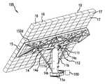
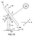
- FIGS. 1A , 1 B, 1 C and 1 Dare an illustration of a solar cell array 105 tracking the sun 102 during different times of the day.
- the Figuresare oriented on the page so that the north direction is out of the page, south is into the page, east is to the left of the page, and west is to the right of the page.
- the solar cell array 105includes a central support ( 11 a , 11 b ) that is fixed to a base 101 .
- the base 101can be, for example, a concrete foundation on a surface of the earth.
- the solar cell array 105also includes a solar panel 10 .
- the solar panel 10is mounted to the central support ( 11 a , 11 b ) by way of a jackscrew 111 , threaded rod 112 and pivot point (e.g., a hinge) 104 .
- the solar panelincludes a generally rectangular array of solar cell receivers (e.g., each receiver including a Fresnel lens and a triple junction III-V compound semiconductor solar cell).
- the panel 10is kept orthogonal to the rays of the sun 102 as the sun 102 traverses across the sky. This is accomplished by rotating the panel about two substantially perpendicular axes to account for the sun's elevation and azimuth.
- an azimuth motorcauses the panel 10 to rotate about axis 103 (i.e., the longitudinal axis of the central support 11 a , 11 b ).
- an elevation motorcauses the translation of the threaded rod 112 in the jackscrew 111 .
- the angle “a” (alpha) shown in FIG. 1Ais the “jack angle” which is used by the software in an embodiment of the present invention.
- FIG. 2illustrates a terrestrial solar cell array 105 in greater detail.
- the solar cell array of FIG. 2is described in co-owned U.S. patent application Ser. No. 12/131,556, filed Jun. 2, 2008, hereby incorporated herein by reference.
- the arraycomprises three major components.
- the first major componentis the central support ( 11 a and 11 b ).
- the central supportis mounted to a surface (e.g., item 101 of FIG. 1A ) and is capable of rotating about its longitudinal axis.
- the surfacecan be, e.g., the ground or a concrete foundation formed in the ground.
- Disposed on or adjacent to the surfaceis a drive mechanism 100 (e.g., azimuth motor 210 of FIG.
- the drive mechanism 100enables the inner member 11 b to rotate relative to the outer member 11 a , e.g., for moving the solar cell array such that it tracks the azimuth of the sun.
- the drive mechanismcan include a motor along with one or more gears.
- the second major componentis the support frame 15 .
- the support frame 15couples to the central support and is adapted to support a solar panel (e.g., panel 10 ).
- the third major componentis the solar panel 10 .
- the solar panel 10includes multiple subarrays 16 and is coupled to, and supported by, the support frame 15 .
- the solar panel 10converts sunlight into electricity, and normally is kept facing the sunlight by the rotation of the central support and adjustment of the jackscrew and threaded rod ( 111 and 112 ).
- each of the solar cell subarrays 16is divided into thirteen sections 17 .
- Each section 17includes a 2 ⁇ 7 panel of concentrating lenses each lens disposed over a single receiver.
- the receivera printed circuit or subassembly, includes a single III-V compound semiconductor solar cell together with additional circuitry such as a bypass diode (not shown).
- each section 17is a module, e.g., a discrete assembly.
- the central supportincludes an outer member 11 a and an inner member 11 b .
- the outer member 11 ais connectable to a support mounted on the surface by bolts.
- the inner member 11 bis rotatably mounted within the member 11 a and supports a cross member 14 which is connected to a support frame 15 .
- the support frame 15also is supported on the inner member 11 b by a pair of inclined arms 14 a which extend respectively from the support frame 15 to the base of the inner member 11 b .
- the inclined arms 14 aare coupled to each other by a cross-member 14 b that increases their structural integrity.
- the mounting of the support frame 15 in this mannerensures that it is fixed to the inner member 11 b of the central support in such a manner that it is rotatable about its central longitudinal axis through members 11 a and 11 b.
- Jackscrew 111 and mating threaded rod 112 togethercan adjust the angle of the panel 10 to track the elevation of the sun.
- the jackscrew 111 in combination with a drive mechanism 111 ae.g., elevation motor 211 of FIG. 2 ) enables pivoting the support frame 15 about hinge 104 , and thus the panel 10 , so as to adjust its angle with respect to the earth's surface.
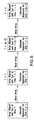
- FIG. 3is a block diagram of an implementation of a terrestrial solar tracking system.
- the systemreceives as input data (a) the date and a future time ( 201 ) and (b) position data of the array ( 202 ), including, e.g., longitude, latitude and elevation above sea level.
- the systemutilizes a future time ( 201 ) rather than the current time so that rather than lagging behind the sun, the array can be oriented to align with the sun at its expected position at the future time.
- the future time ( 201 )is one minute into the future.
- the future time ( 201 )can be sunrise, so that upon sunrise, the solar panel is aligned with the sun at sunrise.
- the future time ( 201 )is at some predetermined time after sunrise that serves as a start up time corresponding to when the solar panel will begin tracking the sun.
- This start up future timeis where the solar panel is first oriented toward the sun for tracking during the day time. While a future time associated with actual sunrise may be used, using a start up time after sunrise allows the solar panel to start tracking the sun from a tilted start up position (e.g., the position of the solar panel in FIG. 1A ), instead of from a fully (or nearly) vertical position facing the sunrise on the horizon.
- the start up position corresponding to this start up timemay be the same as the “parked” (or storage) position of the solar panel during a night mode.
- a start up positionmay be a predetermined angular position of 15 degrees, instead of 0 degrees.
- the systemcan repeat its alignment calculation periodically (e.g., every minute) or continuously.
- the sun position algorithm ( 203 )calculates the position of the sun (e.g., its azimuth and elevation) at that future time ( 204 ).
- the sun position algorithm ( 203 )includes the Solar Position Algorithm (SPA) available from the National Renewable Energy Laboratory (see http://rredc.nrel.gov/solar/codesandalgorithms/spa/ and http://www.nrel.gov/docs/fy08osti/34302.pdf, both of which are incorporated herein by reference).
- SPASolar Position Algorithm
- the sun's azimuth and elevation at the future time ( 204 )are input data to a kinematic model ( 205 ).
- the kinematic model(see FIG. 5 ) correlates movement of the azimuth motor ( 210 ) and the elevation motor ( 211 ) with movement of the solar panel ( 10 ).
- the kinematic model ( 205 )facilitates calculation of the appropriate actuation of the azimuth motor ( 206 ) and the elevation motor ( 207 ) so that the array ( 10 ) is aligned with the sun's elevation and azimuth at the future time ( 204 ).
- Each of the motors ( 210 , 211 )includes a position encoder that determines the current position of each respective motor (e.g., measured by the rotational position of the drive shaft, represented as an integral number of “counts” or increments of a predetermined numbers of degrees, starting from zero and continuing through 360 degrees for one turn, 720 degrees for two turns, etc.).
- the position datais fed back to the motor position calculation ( 206 , 207 ).
- the position encodermay determine position based on a baseline position corresponding to a start up position of the solar panel. As described, this start up position for solar tracking may be one in which the solar panel starts tracking the sun at sunrise. However, in other implementations, this start up position corresponds to a position at a future time after sunrise, at which the solar panel is to start tracking the sun.
- Motor controllersallow the low-power logic signals based on the algorithms to control the relatively high-power circuits of the motors ( 210 , 211 ).
- the azimuth motor 210would be arranged to cause rotation of the panel 10 about axis 103 .
- the elevation motor 211would be couple to the jackscrew 111 and threaded rod 112 so as to adjust the angle of the panel 10 (i.e., rotate the panel 10 about the hinge 104 ). Examples of azimuth and elevation motors are illustrated in FIG. 2 (items 100 and 111 a , respectively).
- the data of blocks 201 - 207can be stored in one or more data stores (e.g., magnetic media, solid state media, or other suitable memory structures).
- the processing of, e.g., blocks 203 and 205 - 209can be performed by, e.g., one or more microprocessors or special or general purpose computers.
- FIG. 4illustrates an implementation 300 of a method for terrestrial solar tracking.
- a block 302determines whether the solar cell array is entering into a one of either a Night mode, where the solar cell array is not activated to collect solar energy, or a Day mode, where the solar cell array is to track the sun and absorb solar energy.
- “night mode”refers to a time frame over which the solar panel is no longer tracking the sun, but rather has been placed in a “parked” position, intermediate position, or otherwise to maintain the solar panel until a Day mode is reached.
- the “night mode”may start before or after sunset, but generally coincides with the night time.
- the “day mode”refers to a time frame over which the solar panel is tracking the sun or is put into a ready, or intermediate position, to begin tracking the sun.
- the “day mode”may start before or after sunrise—preferably it starts at a predetermined time before—but generally coincides with the time from sunrise to sunset when the sun is positioned in the sky and available for tracking, irrespective of obstacles and weather conditions affecting such tracking.
- the block 302determines when the mode is changing from the Day mode to the Night mode or from the Night mode to the Day mode, for example by storing a current mode and comparing that to an identified future mode from a block 304 , which is discussed further below. If the block 302 determines that the solar cell is moving from Day mode to Night mode, then a block 304 sets a future time to a time for entering the solar cell array into a “parked” position. For example, the block 304 may set the future time to sunset or some offset time before or after sunset at which point the solar cell array is to be placed in the “parked” position. In the illustrated example, the block 304 specifically sets the future time to sunset.
- a block 306identifies the “parked” position corresponding to that future time, where the “parked” position is the position that the solar cell array will be kept in during the Night mode.
- the Night modeorients the solar panel 10 into a “parked” position that minimizes damage from weather or other hazards.
- the “parked” positionmay be one pointing away from the night sky or sun.
- the block 306may determine that the appropriate “parked” position is one in which the solar panel 10 is made to point in the expected direction of the next sunrise or the sun some time thereafter.
- the parked positionmay be one in which the solar panel 10 is maintained at an angled position that is neither fully vertical nor fully horizontal.
- the solar panelcan quickly move to a “start up” position for tracking the sun, or to an intermediate “wake up” position where it is held prior to start up.
- the system 300is then able to identify either a position for dormancy during the Night mode, the next position at which the sun will be tracked during the Day mode, or some other position predetermined for storage of the solar panel 10 .
- the examplesare not limited to a particular type of “parked” position that corresponds to the identified future time from block ( 304 ).
- the block 306may set different “parked” positions based on the future time identified at block 304 .
- a block 308sets the future time to some start up time that is sunrise plus some initialization offset time.
- the block 308is described as operating in a Day mode, yet, this mode may be executed at any point after the solar panel 10 has been parked for the Night mode.
- the block 308will typically determine the future time to sunrise and the initialization offset during the night.
- the sunrisemay be a projected sunrise based on calculated or provided data.
- the initialization offset timefor example may be some predetermined time after sunrise that serves as a start up time at which the solar panel will begin tracking the sun.
- the future timemay be sunrise plus 10 minutes, 20 minutes, or 40 minutes, for example.
- the particular future time for start up identified by the block 308may be predetermined or it may be based on a desired sun azimuth and elevation, other than sunrise, at which the solar panel is to start tracking. For example, if the elevation of the sun is less than an elevation minimum for solar tracking, then the system may be designed to wait until the future time when the sun is at the desired azimuth and/or elevation.
- Using a start up time after sunriseallows the solar panel 10 to start tracking the position of the sun from an angled, start up position as determined by the block 309 instead of from an initial vertical position.
- Any other future time values ( 320 )may be measured as an amount of time that has or will have elapsed from the start up time ( 308 ).
- a block 309wakes up the solar panel 10 , preferably at some time, x (minutes), before sunrise.
- This timecorresponds to a time where the actuators, motors, etc. of the solar panel are powered up from a dormant (power save) state to a powered state.
- the value of xis arbitrary and may be set to a few minutes, for example 3 mins, 0 minutes (i.e. sunrise) or otherwise.
- the block 309may calculate or already have stored an identified “wake up” position for the solar panel 10 , where the block 309 commands the motors of the solar panel 10 to position the solar panel into a “wake up” position.
- the time xis set such that the block 309 has sufficient time to move the solar panel 10 into the “wake up” position prior to solar tracking.
- the “wake up” positionmay be the “start up” at which point the solar panel is to begin solar tracking. However, preferably the “wake up” position is an intermediate position, shy of the “start up” position, but sufficiently close to the “start up” position to make movement into that position occur considerably faster than would occur if moving directly from the “parked” position to the “start up” position.
- the solar panelmay be moved into the same pre-start up position every day irrespective of the seasonal position of the sun, weather conditions, etc.
- An intermediate positionmay be chosen, for example, where the solar panel will be held at 3 degrees (elevation) above the highest calculated initial elevation (start up elevation) for solar tracking at any point during the year, i.e., 3 degrees above the highest computed elevation value for P for the year.
- the solar panelmay be positioned within approximately 3 to 10 degrees elevation above the elevation needed for actual “start up” and solar tracking. The solar panel will have a shorter travel distance to get into the “start up” position for tracking, which will eliminate some of the errors and tracking delay that can occur during a solar tracking start up otherwise.
- a block 310computes a desired position, P, of the sun at which tracking by the solar panel is to occur, i.e., corresponding to the “start up” time from the block 308 .
- This calculationmay be of the sun's azimuth and elevation positions at the time identified by the block 308 , namely the projected sunrise time plus some initialization offset.
- blocks 311 and 310form a control loop that determines when the sun is at the desired position, P, to start solar tracking. Once the desired position is reached, the sun is tracked by a tracking process illustrated in the example of FIG. 4 as block 313 .
- the block 310may identify the “start up” position based on the start-up time from block 308 .
- the block 310may set a start up position of 5 degrees above the horizon, for example.
- the exact position of the start up positionmay depend on the particulars of the neighboring geographic terrain, nearby man made obstructions, or for any other reason related to optimizing solar panel usage. If mountains are on the horizon, for example, the angle for this start up position may even be greater than 5 degrees.
- the tracking processmay be initiated, and correspondingly the solar panel may be positioned at a start up position that begins tracking at that time after sunrise. While the blocks 308 , 309 , 310 and 311 are shown separately, these blocks may be combined together into the same algorithm.
- the sun's azimuth and elevation at the future timeare calculated using the sun position algorithm ( 312 ).
- the algorithm ( 312 )will calculate the azimuth and elevation at any future time, not just the start up time.
- the future timecan vary with the implementation, but in some implementations, the future time is one minute into the future, five minutes into the future, or some greater or less amount of time into the future.
- the kinematic modelFor a Day mode, using the sun's elevation and the azimuth, the kinematic model is used to determine the appropriate position of the azimuth and elevation motors (e.g., the rotational position of the drive shafts) to orient the solar cell array such that it is aligned with the sun at the future time ( 314 ). That is, in a Day mode, the kinematic model ( 314 ) starts by determining the appropriate motor positions for the start-up position identified in the block 309 and using the data from the block 312 . After this initialization start-up, the kinematic model ( 314 ) determines the appropriate positions for any future time, as part of the normal solar tracking procedure.
- the azimuth and elevation motorse.g., the rotational position of the drive shafts
- block 316includes precisely controlling the speed of the motors such that, at the future time, the solar panel is aligned with the sun's position at the future time. In some implementations, the motors are operated so that the solar cell array smoothly translates to the appropriate position.
- the kinematic modelis used to determine the appropriate position of the azimuth and elevation motors to orient the solar cell array to the “parked” position identified by the block 306 , and the elevation and azimuth motors are then commanded to the appropriate positions by the block 316 .
- a block 318tracks the current time to determine if the current time is in a region at which a change in mode has occurred. For example, the block 318 determines if the current time is greater than a start-up time threshold, such as after sunrise, sunrise+initialization offset time, or sunrise ⁇ some initial machine ramp up time. Or the block 318 may determine if the current time is greater than a parked time threshold, such as after sunset, sunset+some time, or sunset ⁇ some time. If the current time is in one of these mode changing regions control is passed to the block 302 , as a mode change as been confirmed. Otherwise, control is passed to block 320 which determines the next future time for Day mode solar tracking, and then instructs the block 312 to calculate the sun azimuth and elevation at the new future time.
- a start-up time thresholdsuch as after sunrise, sunrise+initialization offset time, or sunrise ⁇ some initial machine ramp up time.
- a parked time thresholdsuch as after sunset, sunset+some time, or sunset ⁇ some time. If the current
- FIG. 5illustrates an example of solar tracking as a function of time.
- the solar tracking systempredicts the position of the sun at a future time (e.g., one minute into the future) and begins moving the solar cell array so that when the future time arrives, the solar cell array is aligned with the sun's future position.
- the calculating and movingcan be done continuously (e.g., such that the sun's future position is continuously being calculated and the solar cell array is continuously moving) or can be done periodically or intermittently (e.g., every minute, the sun's future position is calculated and the solar cell array is moved).
- the solar cell arrayis aligned with the sun's position at time T.
- the position of the sun at a future time T+1(e.g., one minute into the future) is calculated, as well as the manner of actuating the azimuth and elevation motors based on the kinematic model so that the solar cell array aligns with the sun's position at time T+1.
- the solar cell arrayis moved such that at time T+1, the solar cell array is aligned with the sun's position at time T+1.
- the position of the sun at a future time T+2is calculated, as well as the manner of actuating the azimuth and elevation motors based on the kinematic model so that the solar cell array aligns with the sun's position at time T+2.
- T+ni.e., an arbitrary time in the future
- the solar cell arrayis aligned with the sun at its position at time T+n
- the position of the sun at a future time T+(n+1)is calculated, as well as the manner of actuating the azimuth and elevation motors based on the kinematic model so that the solar cell array aligns with the sun's position at time T+(n+1).
- FIG. 6illustrates an implementation of the kinematic model 205 .
- the kinematic model 205correlates movement of the azimuth and elevation motors with the movement of the solar panel. Therefore, if the desired position of the solar panel is known (e.g., vis-à-vis the position of the sun at a given time), the kinematic model 205 can derive how the motors should be actuated to move the solar cell array to the desired position (e.g., move the azimuth motor driveshaft 0.5 degrees and move the elevation motor driveshaft 2 degrees).
- the kinematic model 205receives several parameters as input data. Some examples are shown in FIG. 6 as blocks 501 - 509 . Generally speaking, while more parameters can provide a more accurate kinematic model, all of blocks 501 - 509 are not required to achieve a functional kinematic model. In fact, since the kinematic model 205 can be tailored for a particular array, entirely different parameters can be used in some implementations. For example, this example presumes that the solar cell array uses geared elevation and axis motors and a jackscrew. Some solar cell arrays can use direct drive and another means for adjusting the angle of the array. Therefore, the parameters are advantageously chosen based on the configuration of the particular array.
- the kinematic model 205receives the pitch of the threaded rod (e.g., item 112 of FIG. 2 ).
- This parameter 501is informative to the model 205 because depending on the thread pitch, more or less rotation will be required to accomplish a given linear translation (e.g., a finer thread pitch requires more rotation to accomplish the same linear translation than a coarser thread pitch).
- the gear ratios ( 502 )are informative for the same reason—they are related to how much the motor driveshafts must rotate to accomplish a given amount of translation of the solar panel.
- the jackscrew data ( 503 )includes information about the jackscrew, such as length and position of the rod, and the angle between the solar panel and the threaded rod.
- This parameter 503affects how much of the linear translation of the threaded rod ( 112 ) is translated into adjusting the angle of the solar panel. For example, if the angle between the solar panel and the threaded rod is about ninety degrees, substantially all of the linear motion of the threaded rod is translated into adjusting the tilt of the solar panel.
- a trigonometric modelcan be used to continuously update this parameter (i.e., 503 can be a dynamic parameter).
- Azimuth and elevation motor home positions ( 505 )are the positions that the controllers for azimuth and elevation motors, respectively, regard as their home positions.
- the elevation home positioncan also be specified by the length of the threaded rod when the elevation motor is in its home position.
- the upper and lower arm distance parameter ( 507 )is herein called out separately and relates to the distance between the top of the threaded rod (e.g., 112 ) of the jackscrew (e.g., 111 ) and the elevation hinge about which the solar panel rotates (e.g., hinge 104 ) and the distance between the bottom of the threaded rod and the elevation hinge.
- This parameter 507duplicates or is related to the jackscrew data parameters ( 503 ) in the sense that it also pertains to the geometry of the elevation adjustment and how translation of the threaded rod translates into changing the elevation angle.
- the zero jack angle parameter ( 508 )is the elevation angle of the solar panel when the jackscrew angle is zero.
- the foregoing parameterscan also affect the speed at which the motors are operated. For example, a finer thread pitch for the jackscrew (parameter 501 ) means that the elevation motor must rotate faster to accomplish a given change in elevation in a given time period as compared to a coarser thread pitch. As another example, a similar concept applies to the motor gear ratios (parameter 502 ).
- parameter 504is directed to the base (e.g., item 101 of FIG. 1A ) pitch and roll.
- the basemight not be perfectly level, and therefore, as the solar panel translates in one direction, an errant translation also can occur in a second direction.
- Parameter 504allows the kinematic model 205 to account for such errors.
- the elevation axise.g., about hinge 104
- the azimuth axise.g., axis 103 .
- variances in construction and/or assemblymay result in the elevation and azimuth axes being non-perpendicular.
- Parameter 506allows the model 205 to account for such an error.
- the plane of the solar panelis perpendicular to the elevation hinge (e.g., hinge 104 ). Variances in construction and/or assembly may result in that not being the case.
- Parameter 509allows the model 205 to account for such an error.
- the kinematic model 205receives parameters 501 - 509 and the sun's position at the future time ( 204 ). With that input data, the kinematic model 205 determines how the motors should be actuated ( 510 ) to align the solar panel with the sun at the future time. The future time ( 204 ) data is further utilized to specify the motor positions ( 510 ).
- the data of blocks 501 - 509can be stored in one or more data stores (e.g., magnetic media, solid state media, or other suitable memory structure).
- the processing of, e.g., blocks 503 and 205can be performed by, e.g., one or more microprocessors or special or general purpose computers.
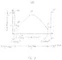
- FIG. 7illustrates a timing diagram 600 for an example implementation of the solar tracking techniques described herein.
- the solar panelis in a “parked” position 602 that was initiated from the Night mode occurring at the rightmost side of the diagram.
- the solar panelis stored at 89 degrees during the morning until a “wake up” time 604 , sunrise ⁇ x mins occurs.
- the solar panelpowers fully up and the motors are controlled to move the solar panel to a “wake up” position 606 , which in the illustrated example corresponds to about 10 degrees elevation (e.g., as identified by block 309 ).
- the exact “wake up” positionmay of course be different, as is the case with the other stored positions described herein.
- the solar panelis held at this position until a start up time 608 has occurred, corresponding to the sunrise time plus initialization offset from block 308 , at which point the solar panel moves from the “wake up” position to the determined “start up” position, from which solar tracking occurs (region 610 ).
- the elevation of the solar panelchanges until dusk.
- the solar panelAs the solar panel tracks the sun, the solar panel eventually approaches another intermediate time 612 corresponding to a “shut down” position 614 where the solar panel is increased to a “shut down” elevation, which is below about 10 degrees in the illustrated example.
- the solar panelis maintained at this “shut down” position, until a “parked” position has been identified and the solar panel is moved into that “parked” position for storage in the Night mode.
- the Day modeextends from the “wake up” time 604 to the “shut down” time 612 .
- the Day modemay start or stop on other time events illustrated in FIG. 7 , such as between “start up” time 608 and a night storage time 616 .
- Embodiments of the subject matter and the functional operations described in this specificationcan be implemented in digital electronic circuitry, or in computer software, firmware, or hardware, including the structures disclosed in this specification and their structural equivalents, or in combinations of one or more of them.
- Embodiments of the subject matter described in this specificationcan be implemented as one or more computer program products, i.e., one or more modules of computer program instructions encoded on a computer readable medium for execution by, or to control the operation of, data processing apparatus.
- the computer readable mediumcan be a machine-readable storage device, a machine-readable storage substrate, a memory device, or a combination of one or more of them.
- data processing apparatusencompasses all apparatus, devices, and machines for processing data, including by way of example a programmable processor, a computer, or multiple processors or computers.
- the apparatuscan include, in addition to hardware, code that creates an execution environment for the computer program in question, e.g., code that constitutes processor firmware, a protocol stack, a database management system, an operating system, a runtime environment or a combination of one or more of them.
- a propagated signalis an artificially generated signal, e.g., a machine-generated electrical, optical, or electromagnetic signal, that is generated to encode information for transmission to a suitable receiver apparatus.
- a computer program(also known as a program, software, software application, script, or code) can be written in any form of programming language, including compiled or interpreted languages, and it can be deployed in any form, including as a stand alone program or as a module, component, subroutine, or other unit suitable for use in a computing environment.
- a computer programdoes not necessarily correspond to a file in a file system.
- a programcan be stored in a portion of a file that holds other programs or data (e.g., one or more scripts stored in a markup language document), in a single file dedicated to the program in question, or in multiple coordinated files (e.g., files that store one or more modules, sub programs, or portions of code).
- a computer programcan be deployed to be executed on one computer or on multiple computers that are located at one site or distributed across multiple sites and interconnected by a communication network.
- the processes and logic flows described in this specificationcan be performed by one or more programmable processors executing one or more computer programs to perform functions by operating on input data and generating output.
- the processes and logic flowscan also be performed by, and apparatus can also be implemented as, special purpose logic circuitry, e.g., an FPGA (field programmable gate array) or an ASIC (application specific integrated circuit).
- processors suitable for the execution of a computer programinclude, by way of example, both general and special purpose microprocessors, and any one or more processors of any kind of digital computer.
- a processorwill receive instructions and data from a read only memory or a random access memory or both.
- the essential elements of a computerare a processor for performing instructions and one or more memory devices for storing instructions and data.
- a computerwill also include, or be operatively coupled to receive data from or transfer data to, or both, one or more mass storage devices for storing data, e.g., magnetic, magneto optical disks, or optical disks.
- mass storage devicesfor storing data, e.g., magnetic, magneto optical disks, or optical disks.
- a computerneed not have such devices.
- a computercan be embedded in another device.
- Computer readable media suitable for storing computer program instructions and datainclude all forms of non volatile memory, media and memory devices, including by way of example semiconductor memory devices, e.g., EPROM, EEPROM, and flash memory devices; magnetic disks, e.g., internal hard disks or removable disks; magneto optical disks; and CD ROM and DVD-ROM disks.
- semiconductor memory devicese.g., EPROM, EEPROM, and flash memory devices
- magnetic diskse.g., internal hard disks or removable disks
- magneto optical diskse.g., CD ROM and DVD-ROM disks.
- the processor and the memorycan be supplemented by, or incorporated in, special purpose logic circuitry.
Landscapes
- Engineering & Computer Science (AREA)
- Sustainable Development (AREA)
- Life Sciences & Earth Sciences (AREA)
- Chemical & Material Sciences (AREA)
- Sustainable Energy (AREA)
- Thermal Sciences (AREA)
- Physics & Mathematics (AREA)
- Combustion & Propulsion (AREA)
- Mechanical Engineering (AREA)
- General Engineering & Computer Science (AREA)
- Architecture (AREA)
- Civil Engineering (AREA)
- Structural Engineering (AREA)
- Photovoltaic Devices (AREA)
Abstract
Description
Claims (14)
Priority Applications (7)
| Application Number | Priority Date | Filing Date | Title |
|---|---|---|---|
| US12/498,135US8513514B2 (en) | 2008-10-24 | 2009-07-06 | Solar tracking for terrestrial solar arrays with variable start and stop positions |
| GB0918669AGB2467197B (en) | 2008-10-24 | 2009-10-23 | Solar tracking for terrestrial solar arrays |
| US12/619,322US8507837B2 (en) | 2008-10-24 | 2009-11-16 | Techniques for monitoring solar array performance and applications thereof |
| US12/830,926US8466399B1 (en) | 2008-10-24 | 2010-07-06 | Techniques for adjusting solar array tracking |
| US13/946,793US8890044B2 (en) | 2008-10-24 | 2013-07-19 | Solar cell system |
| US13/970,235US8946608B2 (en) | 2008-02-01 | 2013-08-19 | Solar tracking system |
| US14/543,310US20150075584A1 (en) | 2008-10-24 | 2014-11-17 | Techniques for monitoring solar array performance and applications thereof |
Applications Claiming Priority (2)
| Application Number | Priority Date | Filing Date | Title |
|---|---|---|---|
| US12/258,253US7795568B2 (en) | 2008-10-24 | 2008-10-24 | Solar tracking for terrestrial solar arrays |
| US12/498,135US8513514B2 (en) | 2008-10-24 | 2009-07-06 | Solar tracking for terrestrial solar arrays with variable start and stop positions |
Related Parent Applications (2)
| Application Number | Title | Priority Date | Filing Date |
|---|---|---|---|
| US12/258,253Continuation-In-PartUS7795568B2 (en) | 2008-02-01 | 2008-10-24 | Solar tracking for terrestrial solar arrays |
| US12/468,747Continuation-In-PartUS8193477B2 (en) | 2008-10-24 | 2009-05-19 | Periodic alignment adjustment techniques for terrestrial solar arrays |
Related Child Applications (3)
| Application Number | Title | Priority Date | Filing Date |
|---|---|---|---|
| US12/258,253Continuation-In-PartUS7795568B2 (en) | 2008-02-01 | 2008-10-24 | Solar tracking for terrestrial solar arrays |
| US12/619,322Continuation-In-PartUS8507837B2 (en) | 2008-10-24 | 2009-11-16 | Techniques for monitoring solar array performance and applications thereof |
| US13/970,235ContinuationUS8946608B2 (en) | 2008-02-01 | 2013-08-19 | Solar tracking system |
Publications (2)
| Publication Number | Publication Date |
|---|---|
| US20100102202A1 US20100102202A1 (en) | 2010-04-29 |
| US8513514B2true US8513514B2 (en) | 2013-08-20 |
Family
ID=42116562
Family Applications (2)
| Application Number | Title | Priority Date | Filing Date |
|---|---|---|---|
| US12/498,135Expired - Fee RelatedUS8513514B2 (en) | 2008-02-01 | 2009-07-06 | Solar tracking for terrestrial solar arrays with variable start and stop positions |
| US13/970,235Expired - Fee RelatedUS8946608B2 (en) | 2008-02-01 | 2013-08-19 | Solar tracking system |
Family Applications After (1)
| Application Number | Title | Priority Date | Filing Date |
|---|---|---|---|
| US13/970,235Expired - Fee RelatedUS8946608B2 (en) | 2008-02-01 | 2013-08-19 | Solar tracking system |
Country Status (1)
| Country | Link |
|---|---|
| US (2) | US8513514B2 (en) |
Cited By (9)
| Publication number | Priority date | Publication date | Assignee | Title |
|---|---|---|---|---|
| US20100185333A1 (en)* | 2009-01-22 | 2010-07-22 | Kenneth Oosting | Feedforward control system for a solar tracker |
| US20140196387A1 (en)* | 2010-08-26 | 2014-07-17 | Christopher Neito | Covered Parking Structure Adjustable Solar Energy Collector Holder and Parking Lot Thereof |
| US20140306092A1 (en)* | 2010-01-18 | 2014-10-16 | Sunpower Corporation | Photovoltaic assembly for use in diffuse weather conditions and related methods |
| US20160009402A1 (en)* | 2012-08-29 | 2016-01-14 | John William Hunter | Solar relay aircraft powered by ground based solar concentrator mirrors in dual use with power towers |
| US9324893B1 (en) | 2013-12-10 | 2016-04-26 | Solaero Technologies Corp. | Portable solar power system and method for the same |
| WO2016145184A2 (en) | 2015-03-10 | 2016-09-15 | KRISHNAN, Neel | A system and method for continuously reorienting the surface of a solar collection device |
| US11466900B2 (en) | 2019-09-20 | 2022-10-11 | King Fahd University Of Petroleum And Minerals | Dual-axis hydraulic system for solar tracking |
| US12410947B2 (en)* | 2021-05-17 | 2025-09-09 | Anywhere.Solar GmbH | Solar instalallation |
| US12431836B1 (en)* | 2025-04-18 | 2025-09-30 | Jingwei Li | Adjustment bracket for solar panel and solar panel |
Families Citing this family (36)
| Publication number | Priority date | Publication date | Assignee | Title |
|---|---|---|---|---|
| US20080086373A1 (en)* | 2006-10-06 | 2008-04-10 | Safeway, Inc. | Nutrition management and meal planning program |
| US8513514B2 (en) | 2008-10-24 | 2013-08-20 | Suncore Photovoltaics, Inc. | Solar tracking for terrestrial solar arrays with variable start and stop positions |
| US8193477B2 (en)* | 2009-05-19 | 2012-06-05 | Emcore Solar Power, Inc. | Periodic alignment adjustment techniques for terrestrial solar arrays |
| US8188415B2 (en)* | 2008-10-24 | 2012-05-29 | Emcore Solar Power, Inc. | Terrestrial solar tracking photovoltaic array |
| US8536504B2 (en) | 2008-10-24 | 2013-09-17 | Suncore Photovoltaics, Inc. | Terrestrial solar tracking photovoltaic array with chain drive |
| US8466399B1 (en) | 2008-10-24 | 2013-06-18 | Suncore Photovoltaics, Inc. | Techniques for adjusting solar array tracking |
| US8188413B2 (en)* | 2008-10-24 | 2012-05-29 | Emcore Solar Power, Inc. | Terrestrial concentrator solar tracking photovoltaic array |
| US8378281B2 (en)* | 2008-10-24 | 2013-02-19 | Suncore Photovoltaics, Inc. | Terrestrial solar tracking photovoltaic array with offset solar cell modules |
| US8507837B2 (en) | 2008-10-24 | 2013-08-13 | Suncore Photovoltaics, Inc. | Techniques for monitoring solar array performance and applications thereof |
| US20110121143A1 (en)* | 2009-08-14 | 2011-05-26 | Schuco International Kg | Tracking system |
| US8168931B1 (en)* | 2009-12-09 | 2012-05-01 | Concrete Systems, Inc. | Solar tracking device |
| US8453328B2 (en) | 2010-06-01 | 2013-06-04 | Suncore Photovoltaics, Inc. | Methods and devices for assembling a terrestrial solar tracking photovoltaic array |
| US8592738B1 (en) | 2010-07-01 | 2013-11-26 | Suncore Photovoltaics, Inc. | Alignment device for use with a solar tracking photovoltaic array |
| CN102340264B (en)* | 2010-07-20 | 2014-01-15 | 威升开发股份有限公司 | Automatic compensation method and device for inclination angle of solar tracking panel |
| US20120152308A1 (en)* | 2010-12-17 | 2012-06-21 | Greenvolts, Inc | Structurally breaking up a two-axis tracker assembly in a concentrated photovoltaic system |
| US8367995B2 (en) | 2011-02-23 | 2013-02-05 | King Fahd University Of Petroleum And Minerals | System and method for automatic positioning of a solar array |
| ES2387775B1 (en)* | 2011-02-28 | 2013-06-06 | Abengoa Solar New Technologies S.A. | SOLAR TRACKER. |
| GB2490335B (en)* | 2011-04-26 | 2013-07-24 | Siemens Plc | Device and method for combining electricity generation from solar power, and water collection from condensing atmospheric vapour |
| WO2013032099A1 (en)* | 2011-08-26 | 2013-03-07 | 주식회사 라온테크 | Solar power generating apparatus |
| US10965241B2 (en)* | 2012-02-05 | 2021-03-30 | Tien Solar LLC | Solar plant support structure |
| US9236751B2 (en)* | 2012-03-09 | 2016-01-12 | Aspect Solar Pte Ltd | Portable modular sun-tracking solar energy receiver system |
| USD721644S1 (en)* | 2012-05-14 | 2015-01-27 | Kyoyo Co., Ltd. | Mount for solar photovoltaic panels |
| US20140090638A1 (en)* | 2012-09-28 | 2014-04-03 | Sunpower Corporation | Sun tracking system |
| KR101316484B1 (en) | 2013-05-03 | 2013-10-08 | 한국항공우주연구원 | Solar propulsion aircraft structure and solar panel control method |
| CN103713651A (en)* | 2013-12-30 | 2014-04-09 | 北京工业大学 | Tracking controller used for linear Fresnel solar condensation power generation system |
| CN104238577B (en)* | 2014-09-24 | 2017-02-15 | 上海律邦新能源科技有限公司 | Biaxial computer-numerical-control positioning method and system of solar panels |
| CN104679033B (en)* | 2015-03-09 | 2017-10-10 | 南京工业职业技术学院 | A kind of sunshine vertical irradiation tracks of device |
| US20170317640A1 (en)* | 2016-04-27 | 2017-11-02 | Mahindra Susten Pvt. Ltd. | Arrangement for angularly displacing solar panels |
| US20180054156A1 (en)* | 2016-08-16 | 2018-02-22 | Roger F. Lokey | Solar Tracker System for Large Utility Scale Solar Capacity |
| US11283395B2 (en) | 2018-03-23 | 2022-03-22 | Nextracker Inc. | Multiple actuator system for solar tracker |
| US11387771B2 (en) | 2018-06-07 | 2022-07-12 | Nextracker Llc | Helical actuator system for solar tracker |
| CN109866637B (en)* | 2019-02-26 | 2020-09-25 | 北京华材中泰科技有限公司 | Solar mobile power generation charging pile |
| US11050383B2 (en) | 2019-05-21 | 2021-06-29 | Nextracker Inc | Radial cam helix with 0 degree stow for solar tracker |
| USD1011272S1 (en) | 2020-07-28 | 2024-01-16 | Palm Energy Systems Llc | Solar collector pillar |
| CN111854190B (en)* | 2020-07-28 | 2021-11-23 | 夏啟忠 | Building block type universal bearing base of solar energy utilization equipment |
| US12259107B1 (en) | 2023-11-15 | 2025-03-25 | Chien Luen Industries Co., Ltd., Inc. | Optimal sunlight detection system for solar luminaires |
Citations (138)
| Publication number | Priority date | Publication date | Assignee | Title |
|---|---|---|---|---|
| US3966499A (en) | 1972-10-11 | 1976-06-29 | The United States Of America As Represented By The Administrator, National Aeronautics And Space Administration | Solar cell grid patterns |
| US4001864A (en) | 1976-01-30 | 1977-01-04 | Gibbons James F | Semiconductor p-n junction solar cell and method of manufacture |
| US4031385A (en) | 1976-04-05 | 1977-06-21 | Desert Sunshine Exposure Tests, Inc. | Solar tracking device |
| US4109640A (en) | 1976-04-12 | 1978-08-29 | Smith Lynwood L | Solar heating system |
| US4172739A (en) | 1977-12-27 | 1979-10-30 | Solar Homes, Inc. | Sun tracker with dual axis support for diurnal movement and seasonal adjustment |
| US4187123A (en) | 1975-10-21 | 1980-02-05 | Diggs Richard E | Directionally controlled array of solar power units |
| US4249514A (en) | 1978-03-09 | 1981-02-10 | Westinghouse Electric Corp. | Tracking solar energy concentrator |
| US4338480A (en) | 1980-12-29 | 1982-07-06 | Varian Associates, Inc. | Stacked multijunction photovoltaic converters |
| US4345582A (en) | 1979-11-19 | 1982-08-24 | Aharon Naaman B | System for the utilization of solar energy |
| US4385198A (en) | 1981-07-08 | 1983-05-24 | The United States Of America As Represented By The Secretary Of The Air Force | Gallium arsenide-germanium heteroface junction device |
| US4425904A (en) | 1980-10-01 | 1984-01-17 | The United States Of America As Represented By The United States Department Of Energy | Tracking system for solar collectors |
| EP0024057B1 (en) | 1979-08-14 | 1984-03-21 | Westinghouse Electric Corporation | Single step formation of pn junction in silicon cell and coating thereon |
| DE3236506A1 (en) | 1982-09-29 | 1984-03-29 | 1000 Berlin Ing. Walter Gruber Gerätebau | Device for energy production by means of solar radiation |
| DE3005876C2 (en) | 1980-02-16 | 1984-09-20 | M.A.N. Maschinenfabrik Augsburg-Nürnberg AG, 8000 München | Photovoltaic solar system |
| US4491681A (en) | 1983-12-08 | 1985-01-01 | The United States Of America As Represented By The United States Department Of Energy | Liquid cooled, linear focus solar cell receiver |
| US4574659A (en) | 1981-08-10 | 1986-03-11 | Zahnraderfabrik Renk, A.G. | Precision drive for positioning solar energy apparatus |
| US4585318A (en) | 1983-01-14 | 1986-04-29 | Dieter Seifert | Tracking device |
| GB2128017B (en) | 1982-09-18 | 1986-05-08 | Fuji Electric Co Ltd | Solar cell unit |
| FR2566183B1 (en) | 1984-06-15 | 1988-01-15 | Luccioni Roger | PHOTOVOLTAIC MODULE WITH INTEGRATED EXCHANGER |
| US4759803A (en) | 1987-08-07 | 1988-07-26 | Applied Solar Energy Corporation | Monolithic solar cell and bypass diode system |
| US4832001A (en) | 1987-05-28 | 1989-05-23 | Zomeworks Corporation | Lightweight solar panel support |
| US4868379A (en) | 1988-06-20 | 1989-09-19 | Utility Power Group | Photovoltaic array with two-axis power maximization tracking |
| US4933022A (en) | 1988-11-14 | 1990-06-12 | Board Of Trustees Of The Leland Stanford Univ. & Electric Power Research Institute | Solar cell having interdigitated contacts and internal bypass diodes |
| US4989124A (en) | 1989-08-21 | 1991-01-29 | Shappell Thomas E | Solar powered sign |
| US4995377A (en) | 1990-06-29 | 1991-02-26 | Eiden Glenn E | Dual axis solar collector assembly |
| US5009720A (en) | 1988-11-16 | 1991-04-23 | Mitsubishi Denki Kabushiki Kaisha | Solar cell |
| US5019177A (en) | 1989-11-03 | 1991-05-28 | The United States Of America As Represented By The United States Department Of Energy | Monolithic tandem solar cell |
| US5022929A (en) | 1989-02-23 | 1991-06-11 | Gallois Montbrun Roger | Solar collector |
| US5053083A (en) | 1989-05-08 | 1991-10-01 | The Board Of Trustees Of The Leland Stanford Junior University | Bilevel contact solar cells |
| US5118361A (en) | 1990-05-21 | 1992-06-02 | The Boeing Company | Terrestrial concentrator solar cell module |
| US5169456A (en) | 1991-10-22 | 1992-12-08 | Johnson Kenneth C | Two-axis tracking solar collector mechanism |
| US5217539A (en) | 1991-09-05 | 1993-06-08 | The Boeing Company | III-V solar cells and doping processes |
| US5228924A (en)* | 1991-11-04 | 1993-07-20 | Mobil Solar Energy Corporation | Photovoltaic panel support assembly |
| US5248346A (en) | 1989-04-17 | 1993-09-28 | The Boeing Company | Photovoltaic cell and array with inherent bypass diode |
| US5317145A (en) | 1991-12-31 | 1994-05-31 | Wattsun Corporation | Radiation source detector and tracker control having a shade pole and radiation responsive surface in the shape of narrow bands |
| US5322572A (en) | 1989-11-03 | 1994-06-21 | The United States Of America As Represented By The United States Department Of Energy | Monolithic tandem solar cell |
| US5330583A (en) | 1991-09-30 | 1994-07-19 | Sharp Kabushiki Kaisha | Solar battery module |
| US5342453A (en) | 1992-11-13 | 1994-08-30 | Midwest Research Institute | Heterojunction solar cell |
| US5376185A (en) | 1993-05-12 | 1994-12-27 | Midwest Research Institute | Single-junction solar cells with the optimum band gap for terrestrial concentrator applications |
| US5389158A (en) | 1989-04-17 | 1995-02-14 | The Boeing Company | Low bandgap photovoltaic cell with inherent bypass diode |
| US5389159A (en) | 1992-09-01 | 1995-02-14 | Canon Kabushiki Kaisha | Solar cell module and method for producing the same |
| EP0464738B1 (en) | 1990-07-04 | 1995-03-15 | Schottel-Werft Josef Becker GmbH & Co KG. | Device for the use of solar energy with solar cells |
| US5405453A (en) | 1993-11-08 | 1995-04-11 | Applied Solar Energy Corporation | High efficiency multi-junction solar cell |
| AU2087695A (en) | 1994-03-31 | 1995-10-23 | Csg Solar Ag | Multiple layer thin film solar cells with buried contacts |
| EP0537781B1 (en) | 1991-10-17 | 1996-12-18 | Sharp Kabushiki Kaisha | Solar cell |
| US5600124A (en) | 1991-12-03 | 1997-02-04 | Berger; Alexander | Sun tracker system for a solar assembly |
| US5616185A (en) | 1995-10-10 | 1997-04-01 | Hughes Aircraft Company | Solar cell with integrated bypass diode and method |
| US5622078A (en) | 1995-08-21 | 1997-04-22 | Mattson; Brad A. | Linear/helix movement support/solar tracker |
| US5632823A (en) | 1996-01-29 | 1997-05-27 | Sharan; Anand M. | Solar tracking system |
| US5798517A (en) | 1994-05-19 | 1998-08-25 | Berger; Alexander | Sun tracker system for a solar assembly |
| EP0789405A3 (en) | 1996-02-07 | 1998-12-30 | Toyota Jidosha Kabushiki Kaisha | Method of cooling solar cells |
| US5944913A (en) | 1997-11-26 | 1999-08-31 | Sandia Corporation | High-efficiency solar cell and method for fabrication |
| US6051776A (en) | 1998-03-11 | 2000-04-18 | Honda Giken Kogyo Kabushiki Kaisha | Light condensing-type solar generator system |
| US6058930A (en) | 1999-04-21 | 2000-05-09 | Shingleton; Jefferson | Solar collector and tracker arrangement |
| US6080927A (en) | 1994-09-15 | 2000-06-27 | Johnson; Colin Francis | Solar concentrator for heat and electricity |
| JP2000196127A (en) | 1998-12-25 | 2000-07-14 | Honda Motor Co Ltd | Fault diagnosing device and fault diagnosing method for concentrating tracking power generation system |
| GB2346010A (en) | 1999-01-25 | 2000-07-26 | Marconi Applied Technologies | Solar cell arrangements |
| JP2000223730A (en) | 1999-02-04 | 2000-08-11 | Honda Motor Co Ltd | Solar tracking type power generation system and operation method thereof |
| US6103970A (en) | 1998-08-20 | 2000-08-15 | Tecstar Power Systems, Inc. | Solar cell having a front-mounted bypass diode |
| ES1044310Y (en) | 1999-05-12 | 2000-09-01 | Llobet Ignasi Sivilla | TWO-AXIS FOLLOWER FOR SOLAR PLATES |
| US6123067A (en) | 1999-03-31 | 2000-09-26 | Amonix, Inc. | Solar collector tracking system |
| US6239354B1 (en) | 1998-10-09 | 2001-05-29 | Midwest Research Institute | Electrical isolation of component cells in monolithically interconnected modules |
| US6252287B1 (en) | 1999-05-19 | 2001-06-26 | Sandia Corporation | InGaAsN/GaAs heterojunction for multi-junction solar cells |
| US6278054B1 (en) | 1998-05-28 | 2001-08-21 | Tecstar Power Systems, Inc. | Solar cell having an integral monolithically grown bypass diode |
| US6281426B1 (en) | 1997-10-01 | 2001-08-28 | Midwest Research Institute | Multi-junction, monolithic solar cell using low-band-gap materials lattice matched to GaAs or Ge |
| US6300557B1 (en) | 1998-10-09 | 2001-10-09 | Midwest Research Institute | Low-bandgap double-heterostructure InAsP/GaInAs photovoltaic converters |
| US6300558B1 (en) | 1999-04-27 | 2001-10-09 | Japan Energy Corporation | Lattice matched solar cell and method for manufacturing the same |
| US6316716B1 (en) | 1999-05-11 | 2001-11-13 | Angewandte Solarenergie - Ase Gmbh | Solar cell and method for producing such a cell |
| US6340788B1 (en) | 1999-12-02 | 2002-01-22 | Hughes Electronics Corporation | Multijunction photovoltaic cells and panels using a silicon or silicon-germanium active substrate cell for space and terrestrial applications |
| US20020040727A1 (en) | 2000-06-20 | 2002-04-11 | Stan Mark A. | Apparatus and method for optimizing the efficiency of germanium junctions in multi-junction solar cells |
| US6372980B1 (en) | 1995-12-06 | 2002-04-16 | University Of Houston | Multi-quantum well tandem solar cell |
| US6399874B1 (en) | 2001-01-11 | 2002-06-04 | Charles Dennehy, Jr. | Solar energy module and fresnel lens for use in same |
| JP2002202817A (en) | 2000-12-28 | 2002-07-19 | Rhythm Watch Co Ltd | Sun tracking system |
| US6452086B1 (en) | 1998-10-05 | 2002-09-17 | Astrium Gmbh | Solar cell comprising a bypass diode |
| US6465725B1 (en) | 2000-01-31 | 2002-10-15 | Honda Giken Kogyo Kabushiki Kaisha | Tracking type photovoltaic power generator and error correction method of its built-in clock |
| US20020164834A1 (en) | 1999-07-14 | 2002-11-07 | Boutros Karim S. | Monolithic bypass-diode and solar-cell string assembly |
| US6483093B1 (en) | 1999-11-24 | 2002-11-19 | Honda Giken Kogyo Kabushiki Kaisha | Solar generator system |
| US6482672B1 (en) | 1997-11-06 | 2002-11-19 | Essential Research, Inc. | Using a critical composition grading technique to deposit InGaAs epitaxial layers on InP substrates |
| US20030000564A1 (en) | 2001-06-27 | 2003-01-02 | Shingleton Jefferson G. | High-concentration photovoltaic assembly for a utility-scale power generation system |
| US20030066555A1 (en) | 2000-12-04 | 2003-04-10 | Hui Ron Shu Yuen | Maximum power tracking technique for solar panels |
| US20030070707A1 (en) | 2001-10-12 | 2003-04-17 | King Richard Roland | Wide-bandgap, lattice-mismatched window layer for a solar energy conversion device |
| US6552257B1 (en) | 2001-10-16 | 2003-04-22 | American Signal Company | Nonrotating pivotable solar panel |
| US20030075215A1 (en) | 2001-10-24 | 2003-04-24 | Sharps Paul R. | Apparatus and method for optimizing the efficiency of a bypass diode in multijunction solar cells |
| US6563040B2 (en) | 2001-10-11 | 2003-05-13 | Pinnacle West Capital Corporation | Structure for supporting a photovoltaic module in a solar energy collection system |
| EP1126529A3 (en) | 2000-02-18 | 2003-07-16 | S.I.E.M. S.r.l. | Solar and photovoltaic panel with energy regeneration and automatic sun tracking |
| US20030140962A1 (en) | 2001-10-24 | 2003-07-31 | Sharps Paul R. | Apparatus and method for integral bypass diode in solar cells |
| US20030145884A1 (en) | 2001-10-12 | 2003-08-07 | King Richard Roland | Wide-bandgap, lattice-mismatched window layer for a solar conversion device |
| US6660928B1 (en) | 2002-04-02 | 2003-12-09 | Essential Research, Inc. | Multi-junction photovoltaic cell |
| US20040031517A1 (en) | 2002-08-13 | 2004-02-19 | Bareis Bernard F. | Concentrating solar energy receiver |
| US6696637B2 (en) | 2001-05-29 | 2004-02-24 | The Sun Trust, L.L.C. | Conversion of solar energy |
| US20040045598A1 (en) | 2002-09-06 | 2004-03-11 | The Boeing Company | Multi-junction photovoltaic cell having buffer layers for the growth of single crystal boron compounds |
| JP2004153202A (en) | 2002-11-01 | 2004-05-27 | Daido Steel Co Ltd | Concentrating solar power generator |
| US20040112424A1 (en) | 2002-10-03 | 2004-06-17 | Daido Steel Co., Ltd. | Solar cell assembly, and photovoltaic solar electric generator of concentrator type |
| US20040112373A1 (en) | 2002-12-09 | 2004-06-17 | Derek Djeu | Passive Solar Tracker for a Solar Concentrator |
| DE10343374A1 (en) | 2003-09-17 | 2004-12-23 | Werner Herz | Sun direction following unit for photovoltaic or thermal solar energy collection has console for collectors on a frame that can rotate on a ring |
| DE202005002411U1 (en) | 2005-02-14 | 2005-04-21 | A & F Stahl- Und Maschinenbau Gmbh | Rack for storage of solar modules |
| US20050121071A1 (en) | 2003-09-24 | 2005-06-09 | C.R.F. Societa Consortile Per Azioni | Multifocal light concentrator for a device for the conversion of radiation, and in particular for the conversion of solar radiation into electrical, thermal or chemical energy |
| US6951819B2 (en) | 2002-12-05 | 2005-10-04 | Blue Photonics, Inc. | High efficiency, monolithic multijunction solar cells containing lattice-mismatched materials and methods of forming same |
| US20050274409A1 (en) | 2004-06-15 | 2005-12-15 | The Boeing Company | Multijunction solar cell having a lattice mismatched GrIII-GrV-X layer and a composition-graded buffer layer |
| US20050284467A1 (en) | 2002-10-17 | 2005-12-29 | Patterson Michael T | Solar tracking apparatus |
| US20060054162A1 (en) | 2004-09-03 | 2006-03-16 | Romeo Manuel L | Solar tracker |
| US7071407B2 (en) | 2002-10-31 | 2006-07-04 | Emcore Corporation | Method and apparatus of multiplejunction solar cell structure with high band gap heterojunction middle cell |
| US20060144435A1 (en) | 2002-05-21 | 2006-07-06 | Wanlass Mark W | High-efficiency, monolithic, multi-bandgap, tandem photovoltaic energy converters |
| US20060162768A1 (en) | 2002-05-21 | 2006-07-27 | Wanlass Mark W | Low bandgap, monolithic, multi-bandgap, optoelectronic devices |
| US7109461B2 (en) | 2001-03-28 | 2006-09-19 | Solar Systems Pty Ltd. | Solar tracking system |
| CN2882108Y (en) | 2006-03-06 | 2007-03-21 | 方辉 | High-efficient collection device for solar battery |
| US20070079863A1 (en) | 2005-10-11 | 2007-04-12 | Emcore Corporation | Reliable interconnection of solar cells including integral bypass diode |
| US20070089777A1 (en) | 2005-10-04 | 2007-04-26 | Johnson Richard L Jr | Heatsink for concentrating or focusing optical/electrical energy conversion systems |
| US20070101738A1 (en) | 2005-11-09 | 2007-05-10 | Masao Akei | Vapor compression circuit and method including a thermoelectric device |
| EP1788322A1 (en) | 2005-11-19 | 2007-05-23 | Goldbeck Solar GmbH | Mounting for an assembly of solar modules |
| US7252084B2 (en) | 2004-06-28 | 2007-08-07 | Lucent Technologies Inc. | Solar tracking system |
| US20070188876A1 (en) | 2006-01-17 | 2007-08-16 | Hines Braden E | Hybrid primary optical component for optical concentrators |
| US20070193620A1 (en) | 2006-01-17 | 2007-08-23 | Hines Braden E | Concentrating solar panel and related systems and methods |
| US20070215199A1 (en) | 2006-03-16 | 2007-09-20 | United Technologies Corporation | Solar tracker |
| US20070246095A1 (en) | 2006-04-20 | 2007-10-25 | Hydrogain Technologies, Inc. | Apparatus for generating electrical power from solar radiation concentrated by a concave reflector |
| WO2008008023A1 (en) | 2006-07-13 | 2008-01-17 | Karim Ibrahim Najar | Solar collector |
| US7381886B1 (en) | 2007-07-30 | 2008-06-03 | Emcore Corporation | Terrestrial solar array |
| US20080128586A1 (en) | 2006-10-13 | 2008-06-05 | Johnson Richard L | Sun sensor assembly and related method of using |
| US20080135087A1 (en) | 2007-05-10 | 2008-06-12 | Rangappan Anikara | Thin solar concentrator |
| US20080178867A1 (en) | 2007-01-30 | 2008-07-31 | Xtreme Energetics Inc | Solid-state sun tracker |
| US20080258051A1 (en) | 2007-04-11 | 2008-10-23 | Solfocus, Inc. | Equipment and Process for Measuring the Precision of Sun Tracking for Photovoltaic Concentrators |
| US20080290252A1 (en) | 2007-05-23 | 2008-11-27 | Sma Technologie Ag | Power matching method |
| US20090000662A1 (en) | 2007-03-11 | 2009-01-01 | Harwood Duncan W J | Photovoltaic receiver for solar concentrator applications |
| US20090032014A1 (en) | 2007-07-31 | 2009-02-05 | Yevgeny Meydbray | Variable tilt tracker for photovoltaic arrays |
| US20090126774A1 (en) | 2007-10-12 | 2009-05-21 | Taylor Ii Russell M | Methods, systems, and computer readable media for controlling orientation of a photovoltaic collection system to track apparent movement of the sun |
| US20090179139A1 (en) | 2006-03-30 | 2009-07-16 | Hines Braden E | Tracking solar collector |
| US20100011565A1 (en) | 2008-07-21 | 2010-01-21 | Emcore Corporation | Methods of forming a lens sheet for a photovoltaic solar cell system |
| US20100018570A1 (en) | 2008-05-16 | 2010-01-28 | Cashion Steven A | Concentrating photovoltaic solar panel |
| US20100023138A1 (en) | 2008-07-24 | 2010-01-28 | Mcdonald Mark | System to increase snr of cpv-generated power signal |
| US20100102200A1 (en) | 2008-10-24 | 2010-04-29 | Emcore Solar Power, Inc. | Terrestrial Solar Tracking Photovoltaic Array |
| US20100102202A1 (en) | 2008-10-24 | 2010-04-29 | Emcore Solar Power, Inc, | Solar Tracking for Terrestrial Solar Arrays with Variable Start and Stop Positions |
| US20100101630A1 (en) | 2008-10-24 | 2010-04-29 | Emcore Solar Power, Inc. | Terrestrial Solar Tracking Photovoltaic Array with Slew Speed Reducer |
| US20100101625A1 (en) | 2008-10-24 | 2010-04-29 | Emcore Solar Power, Inc. | Terrestrial Solar Tracking Photovoltaic Array |
| US20100101632A1 (en) | 2008-10-24 | 2010-04-29 | Emcore Solar Power, Inc. | Terrestrial Solar Tracking Photovoltaic Array With Offset Solar Cell Modules |
| US20100102201A1 (en) | 2008-10-24 | 2010-04-29 | Emcore Solar Power, Inc. | Solar Tracking for Terrestrial Solar Arrays |
| US20100108860A1 (en) | 2008-10-24 | 2010-05-06 | Emcore Solar Power, Inc. | Techniques for Monitoring Solar Array Performance and Applications Thereof |
| US20100294337A1 (en) | 2009-05-19 | 2010-11-25 | Emcore Solar Power, Inc. | Periodic Alignment Adjustment Techniques for Terrestrial Solar Arrays |
| US20110289750A1 (en) | 2010-06-01 | 2011-12-01 | Emcore Solar Power, Inc. | Methods and Devices for Assembling a Terrestrial Solar Tracking Photovoltaic Array |
Family Cites Families (16)
| Publication number | Priority date | Publication date | Assignee | Title |
|---|---|---|---|---|
| US4583318A (en)* | 1983-05-10 | 1986-04-22 | Richardson John W | Apparatus and method for direct application of treatment liquid to growing vegetation |
| JPS60160181U (en) | 1984-04-02 | 1985-10-24 | 鈴木 吉成 | Processed foods shaped like lucky charms |
| AUPM996094A0 (en) | 1994-12-08 | 1995-01-05 | Pacific Solar Pty Limited | Multilayer solar cells with bypass diode protection |
| JP3583871B2 (en) | 1996-08-23 | 2004-11-04 | 積水化学工業株式会社 | Photovoltaic-heat collecting hybrid panel, and roof panel, roof unit, solar system and solar system building comprising the photovoltaic-heat collecting hybrid panel |
| WO1999062125A1 (en) | 1998-05-28 | 1999-12-02 | Tecstar Power Systems, Inc. | Solar cell having an integral monolithically grown bypass diode |
| AUPR403801A0 (en) | 2001-03-28 | 2001-04-26 | Solar Systems Pty Ltd | System for generating electrical power from solar radiation |
| US20060014435A1 (en)* | 2004-07-14 | 2006-01-19 | P-Two Industries Inc. | Card connector |
| US8062230B1 (en)* | 2004-10-14 | 2011-11-22 | Suros Surgical Systems, Inc. | Surgical site marker delivery system |
| US7476832B2 (en) | 2006-06-29 | 2009-01-13 | Herb Vendig | Seasonally adjustable mounting system for solar panels having dual motor assembly |
| US20080041440A1 (en) | 2006-08-16 | 2008-02-21 | O'connell Daniel G | Solar panel condenser |
| US8578929B2 (en) | 2007-06-21 | 2013-11-12 | Voltwerk Electronics Gmbh | Modular pivotable solar collector arrangement |
| US20090188488A1 (en) | 2008-01-28 | 2009-07-30 | Tilt Solar Llc | Wireless mesh networking of solar tracking devices |
| US20100018519A1 (en)* | 2008-07-24 | 2010-01-28 | Mcdonald Mark | Fault monitoring based on solar tracking error |
| US8466399B1 (en) | 2008-10-24 | 2013-06-18 | Suncore Photovoltaics, Inc. | Techniques for adjusting solar array tracking |
| US20100175741A1 (en) | 2009-01-13 | 2010-07-15 | John Danhakl | Dual Axis Sun-Tracking Solar Panel Array |
| US8592738B1 (en) | 2010-07-01 | 2013-11-26 | Suncore Photovoltaics, Inc. | Alignment device for use with a solar tracking photovoltaic array |
- 2009
- 2009-07-06USUS12/498,135patent/US8513514B2/ennot_activeExpired - Fee Related
- 2013
- 2013-08-19USUS13/970,235patent/US8946608B2/ennot_activeExpired - Fee Related
Patent Citations (153)
| Publication number | Priority date | Publication date | Assignee | Title |
|---|---|---|---|---|
| US3966499A (en) | 1972-10-11 | 1976-06-29 | The United States Of America As Represented By The Administrator, National Aeronautics And Space Administration | Solar cell grid patterns |
| US4187123A (en) | 1975-10-21 | 1980-02-05 | Diggs Richard E | Directionally controlled array of solar power units |
| US4001864A (en) | 1976-01-30 | 1977-01-04 | Gibbons James F | Semiconductor p-n junction solar cell and method of manufacture |
| US4031385A (en) | 1976-04-05 | 1977-06-21 | Desert Sunshine Exposure Tests, Inc. | Solar tracking device |
| US4109640A (en) | 1976-04-12 | 1978-08-29 | Smith Lynwood L | Solar heating system |
| US4172739A (en) | 1977-12-27 | 1979-10-30 | Solar Homes, Inc. | Sun tracker with dual axis support for diurnal movement and seasonal adjustment |
| US4249514A (en) | 1978-03-09 | 1981-02-10 | Westinghouse Electric Corp. | Tracking solar energy concentrator |
| EP0024057B1 (en) | 1979-08-14 | 1984-03-21 | Westinghouse Electric Corporation | Single step formation of pn junction in silicon cell and coating thereon |
| US4345582A (en) | 1979-11-19 | 1982-08-24 | Aharon Naaman B | System for the utilization of solar energy |
| DE3005876C2 (en) | 1980-02-16 | 1984-09-20 | M.A.N. Maschinenfabrik Augsburg-Nürnberg AG, 8000 München | Photovoltaic solar system |
| US4425904A (en) | 1980-10-01 | 1984-01-17 | The United States Of America As Represented By The United States Department Of Energy | Tracking system for solar collectors |
| US4338480A (en) | 1980-12-29 | 1982-07-06 | Varian Associates, Inc. | Stacked multijunction photovoltaic converters |
| US4385198A (en) | 1981-07-08 | 1983-05-24 | The United States Of America As Represented By The Secretary Of The Air Force | Gallium arsenide-germanium heteroface junction device |
| US4574659A (en) | 1981-08-10 | 1986-03-11 | Zahnraderfabrik Renk, A.G. | Precision drive for positioning solar energy apparatus |
| GB2128017B (en) | 1982-09-18 | 1986-05-08 | Fuji Electric Co Ltd | Solar cell unit |
| DE3236506A1 (en) | 1982-09-29 | 1984-03-29 | 1000 Berlin Ing. Walter Gruber Gerätebau | Device for energy production by means of solar radiation |
| US4585318A (en) | 1983-01-14 | 1986-04-29 | Dieter Seifert | Tracking device |
| US4491681A (en) | 1983-12-08 | 1985-01-01 | The United States Of America As Represented By The United States Department Of Energy | Liquid cooled, linear focus solar cell receiver |
| FR2566183B1 (en) | 1984-06-15 | 1988-01-15 | Luccioni Roger | PHOTOVOLTAIC MODULE WITH INTEGRATED EXCHANGER |
| US4832001A (en) | 1987-05-28 | 1989-05-23 | Zomeworks Corporation | Lightweight solar panel support |
| US4759803A (en) | 1987-08-07 | 1988-07-26 | Applied Solar Energy Corporation | Monolithic solar cell and bypass diode system |
| US4868379A (en) | 1988-06-20 | 1989-09-19 | Utility Power Group | Photovoltaic array with two-axis power maximization tracking |
| US4933022A (en) | 1988-11-14 | 1990-06-12 | Board Of Trustees Of The Leland Stanford Univ. & Electric Power Research Institute | Solar cell having interdigitated contacts and internal bypass diodes |
| US5009720A (en) | 1988-11-16 | 1991-04-23 | Mitsubishi Denki Kabushiki Kaisha | Solar cell |
| EP0369666B1 (en) | 1988-11-16 | 1995-06-14 | Mitsubishi Denki Kabushiki Kaisha | Solar cell |
| US5022929A (en) | 1989-02-23 | 1991-06-11 | Gallois Montbrun Roger | Solar collector |
| US5248346A (en) | 1989-04-17 | 1993-09-28 | The Boeing Company | Photovoltaic cell and array with inherent bypass diode |
| US5389158A (en) | 1989-04-17 | 1995-02-14 | The Boeing Company | Low bandgap photovoltaic cell with inherent bypass diode |
| US5053083A (en) | 1989-05-08 | 1991-10-01 | The Board Of Trustees Of The Leland Stanford Junior University | Bilevel contact solar cells |
| US4989124A (en) | 1989-08-21 | 1991-01-29 | Shappell Thomas E | Solar powered sign |
| US5322572A (en) | 1989-11-03 | 1994-06-21 | The United States Of America As Represented By The United States Department Of Energy | Monolithic tandem solar cell |
| US5019177A (en) | 1989-11-03 | 1991-05-28 | The United States Of America As Represented By The United States Department Of Energy | Monolithic tandem solar cell |
| US5118361A (en) | 1990-05-21 | 1992-06-02 | The Boeing Company | Terrestrial concentrator solar cell module |
| US4995377A (en) | 1990-06-29 | 1991-02-26 | Eiden Glenn E | Dual axis solar collector assembly |
| EP0464738B1 (en) | 1990-07-04 | 1995-03-15 | Schottel-Werft Josef Becker GmbH & Co KG. | Device for the use of solar energy with solar cells |
| US5217539A (en) | 1991-09-05 | 1993-06-08 | The Boeing Company | III-V solar cells and doping processes |
| US5330583A (en) | 1991-09-30 | 1994-07-19 | Sharp Kabushiki Kaisha | Solar battery module |
| EP0537781B1 (en) | 1991-10-17 | 1996-12-18 | Sharp Kabushiki Kaisha | Solar cell |
| US5169456A (en) | 1991-10-22 | 1992-12-08 | Johnson Kenneth C | Two-axis tracking solar collector mechanism |
| US5228924A (en)* | 1991-11-04 | 1993-07-20 | Mobil Solar Energy Corporation | Photovoltaic panel support assembly |
| US5600124A (en) | 1991-12-03 | 1997-02-04 | Berger; Alexander | Sun tracker system for a solar assembly |
| US5317145A (en) | 1991-12-31 | 1994-05-31 | Wattsun Corporation | Radiation source detector and tracker control having a shade pole and radiation responsive surface in the shape of narrow bands |
| US5389159A (en) | 1992-09-01 | 1995-02-14 | Canon Kabushiki Kaisha | Solar cell module and method for producing the same |
| US5342453A (en) | 1992-11-13 | 1994-08-30 | Midwest Research Institute | Heterojunction solar cell |
| US5376185A (en) | 1993-05-12 | 1994-12-27 | Midwest Research Institute | Single-junction solar cells with the optimum band gap for terrestrial concentrator applications |
| US5405453A (en) | 1993-11-08 | 1995-04-11 | Applied Solar Energy Corporation | High efficiency multi-junction solar cell |
| AU2087695A (en) | 1994-03-31 | 1995-10-23 | Csg Solar Ag | Multiple layer thin film solar cells with buried contacts |
| US5798517A (en) | 1994-05-19 | 1998-08-25 | Berger; Alexander | Sun tracker system for a solar assembly |
| US6080927A (en) | 1994-09-15 | 2000-06-27 | Johnson; Colin Francis | Solar concentrator for heat and electricity |
| US5622078A (en) | 1995-08-21 | 1997-04-22 | Mattson; Brad A. | Linear/helix movement support/solar tracker |
| US5616185A (en) | 1995-10-10 | 1997-04-01 | Hughes Aircraft Company | Solar cell with integrated bypass diode and method |
| US6372980B1 (en) | 1995-12-06 | 2002-04-16 | University Of Houston | Multi-quantum well tandem solar cell |
| US5632823A (en) | 1996-01-29 | 1997-05-27 | Sharan; Anand M. | Solar tracking system |
| EP0789405A3 (en) | 1996-02-07 | 1998-12-30 | Toyota Jidosha Kabushiki Kaisha | Method of cooling solar cells |
| US6281426B1 (en) | 1997-10-01 | 2001-08-28 | Midwest Research Institute | Multi-junction, monolithic solar cell using low-band-gap materials lattice matched to GaAs or Ge |
| US6482672B1 (en) | 1997-11-06 | 2002-11-19 | Essential Research, Inc. | Using a critical composition grading technique to deposit InGaAs epitaxial layers on InP substrates |
| US5944913A (en) | 1997-11-26 | 1999-08-31 | Sandia Corporation | High-efficiency solar cell and method for fabrication |
| US6051776A (en) | 1998-03-11 | 2000-04-18 | Honda Giken Kogyo Kabushiki Kaisha | Light condensing-type solar generator system |
| US6359210B2 (en) | 1998-05-28 | 2002-03-19 | Tecstar Power System, Inc. | Solar cell having an integral monolithically grown bypass diode |
| US6600100B2 (en) | 1998-05-28 | 2003-07-29 | Emcore Corporation | Solar cell having an integral monolithically grown bypass diode |
| US6278054B1 (en) | 1998-05-28 | 2001-08-21 | Tecstar Power Systems, Inc. | Solar cell having an integral monolithically grown bypass diode |
| US6103970A (en) | 1998-08-20 | 2000-08-15 | Tecstar Power Systems, Inc. | Solar cell having a front-mounted bypass diode |
| US6326540B1 (en) | 1998-08-20 | 2001-12-04 | Tecstar Power Systems, Inc. | Solar cell having a front-mounted bypass diode |
| US6452086B1 (en) | 1998-10-05 | 2002-09-17 | Astrium Gmbh | Solar cell comprising a bypass diode |
| US6239354B1 (en) | 1998-10-09 | 2001-05-29 | Midwest Research Institute | Electrical isolation of component cells in monolithically interconnected modules |
| US6300557B1 (en) | 1998-10-09 | 2001-10-09 | Midwest Research Institute | Low-bandgap double-heterostructure InAsP/GaInAs photovoltaic converters |
| JP2000196127A (en) | 1998-12-25 | 2000-07-14 | Honda Motor Co Ltd | Fault diagnosing device and fault diagnosing method for concentrating tracking power generation system |
| GB2346010A (en) | 1999-01-25 | 2000-07-26 | Marconi Applied Technologies | Solar cell arrangements |
| JP2000223730A (en) | 1999-02-04 | 2000-08-11 | Honda Motor Co Ltd | Solar tracking type power generation system and operation method thereof |
| US6123067A (en) | 1999-03-31 | 2000-09-26 | Amonix, Inc. | Solar collector tracking system |
| US6058930A (en) | 1999-04-21 | 2000-05-09 | Shingleton; Jefferson | Solar collector and tracker arrangement |
| US6300558B1 (en) | 1999-04-27 | 2001-10-09 | Japan Energy Corporation | Lattice matched solar cell and method for manufacturing the same |
| US6316716B1 (en) | 1999-05-11 | 2001-11-13 | Angewandte Solarenergie - Ase Gmbh | Solar cell and method for producing such a cell |
| ES1044310Y (en) | 1999-05-12 | 2000-09-01 | Llobet Ignasi Sivilla | TWO-AXIS FOLLOWER FOR SOLAR PLATES |
| US6252287B1 (en) | 1999-05-19 | 2001-06-26 | Sandia Corporation | InGaAsN/GaAs heterojunction for multi-junction solar cells |
| US20020164834A1 (en) | 1999-07-14 | 2002-11-07 | Boutros Karim S. | Monolithic bypass-diode and solar-cell string assembly |
| US6483093B1 (en) | 1999-11-24 | 2002-11-19 | Honda Giken Kogyo Kabushiki Kaisha | Solar generator system |
| US6340788B1 (en) | 1999-12-02 | 2002-01-22 | Hughes Electronics Corporation | Multijunction photovoltaic cells and panels using a silicon or silicon-germanium active substrate cell for space and terrestrial applications |
| US6465725B1 (en) | 2000-01-31 | 2002-10-15 | Honda Giken Kogyo Kabushiki Kaisha | Tracking type photovoltaic power generator and error correction method of its built-in clock |
| EP1126529A3 (en) | 2000-02-18 | 2003-07-16 | S.I.E.M. S.r.l. | Solar and photovoltaic panel with energy regeneration and automatic sun tracking |
| US20020040727A1 (en) | 2000-06-20 | 2002-04-11 | Stan Mark A. | Apparatus and method for optimizing the efficiency of germanium junctions in multi-junction solar cells |
| US20030066555A1 (en) | 2000-12-04 | 2003-04-10 | Hui Ron Shu Yuen | Maximum power tracking technique for solar panels |
| JP2002202817A (en) | 2000-12-28 | 2002-07-19 | Rhythm Watch Co Ltd | Sun tracking system |
| US6399874B1 (en) | 2001-01-11 | 2002-06-04 | Charles Dennehy, Jr. | Solar energy module and fresnel lens for use in same |
| US7109461B2 (en) | 2001-03-28 | 2006-09-19 | Solar Systems Pty Ltd. | Solar tracking system |
| US6696637B2 (en) | 2001-05-29 | 2004-02-24 | The Sun Trust, L.L.C. | Conversion of solar energy |
| US20030000564A1 (en) | 2001-06-27 | 2003-01-02 | Shingleton Jefferson G. | High-concentration photovoltaic assembly for a utility-scale power generation system |
| US6563040B2 (en) | 2001-10-11 | 2003-05-13 | Pinnacle West Capital Corporation | Structure for supporting a photovoltaic module in a solar energy collection system |
| US20030145884A1 (en) | 2001-10-12 | 2003-08-07 | King Richard Roland | Wide-bandgap, lattice-mismatched window layer for a solar conversion device |
| US20030070707A1 (en) | 2001-10-12 | 2003-04-17 | King Richard Roland | Wide-bandgap, lattice-mismatched window layer for a solar energy conversion device |
| US6552257B1 (en) | 2001-10-16 | 2003-04-22 | American Signal Company | Nonrotating pivotable solar panel |
| US6960717B2 (en) | 2001-10-16 | 2005-11-01 | American Signal Company | Adjustable solar panel |
| US6680432B2 (en) | 2001-10-24 | 2004-01-20 | Emcore Corporation | Apparatus and method for optimizing the efficiency of a bypass diode in multijunction solar cells |
| US20030140962A1 (en) | 2001-10-24 | 2003-07-31 | Sharps Paul R. | Apparatus and method for integral bypass diode in solar cells |
| US20030075215A1 (en) | 2001-10-24 | 2003-04-24 | Sharps Paul R. | Apparatus and method for optimizing the efficiency of a bypass diode in multijunction solar cells |
| US20040149331A1 (en) | 2001-10-24 | 2004-08-05 | Sharps Paul R. | Apparatus and method for optimizing the efficiency of a bypass diode in solar cells |
| US6660928B1 (en) | 2002-04-02 | 2003-12-09 | Essential Research, Inc. | Multi-junction photovoltaic cell |
| US20060162768A1 (en) | 2002-05-21 | 2006-07-27 | Wanlass Mark W | Low bandgap, monolithic, multi-bandgap, optoelectronic devices |
| US20060144435A1 (en) | 2002-05-21 | 2006-07-06 | Wanlass Mark W | High-efficiency, monolithic, multi-bandgap, tandem photovoltaic energy converters |
| US20040031517A1 (en) | 2002-08-13 | 2004-02-19 | Bareis Bernard F. | Concentrating solar energy receiver |
| US20040045598A1 (en) | 2002-09-06 | 2004-03-11 | The Boeing Company | Multi-junction photovoltaic cell having buffer layers for the growth of single crystal boron compounds |
| US20040112424A1 (en) | 2002-10-03 | 2004-06-17 | Daido Steel Co., Ltd. | Solar cell assembly, and photovoltaic solar electric generator of concentrator type |
| US20050284467A1 (en) | 2002-10-17 | 2005-12-29 | Patterson Michael T | Solar tracking apparatus |
| US7071407B2 (en) | 2002-10-31 | 2006-07-04 | Emcore Corporation | Method and apparatus of multiplejunction solar cell structure with high band gap heterojunction middle cell |
| JP2004153202A (en) | 2002-11-01 | 2004-05-27 | Daido Steel Co Ltd | Concentrating solar power generator |
| US6951819B2 (en) | 2002-12-05 | 2005-10-04 | Blue Photonics, Inc. | High efficiency, monolithic multijunction solar cells containing lattice-mismatched materials and methods of forming same |
| US20040112373A1 (en) | 2002-12-09 | 2004-06-17 | Derek Djeu | Passive Solar Tracker for a Solar Concentrator |
| DE10343374A1 (en) | 2003-09-17 | 2004-12-23 | Werner Herz | Sun direction following unit for photovoltaic or thermal solar energy collection has console for collectors on a frame that can rotate on a ring |
| US20050121071A1 (en) | 2003-09-24 | 2005-06-09 | C.R.F. Societa Consortile Per Azioni | Multifocal light concentrator for a device for the conversion of radiation, and in particular for the conversion of solar radiation into electrical, thermal or chemical energy |
| US20050274409A1 (en) | 2004-06-15 | 2005-12-15 | The Boeing Company | Multijunction solar cell having a lattice mismatched GrIII-GrV-X layer and a composition-graded buffer layer |
| US7252084B2 (en) | 2004-06-28 | 2007-08-07 | Lucent Technologies Inc. | Solar tracking system |
| US20060054162A1 (en) | 2004-09-03 | 2006-03-16 | Romeo Manuel L | Solar tracker |
| ES2253099B1 (en) | 2004-09-03 | 2007-05-01 | Manuel Lahuerta Romeo | SOLAR TRACKER. |
| EP1691423A3 (en) | 2005-02-14 | 2007-04-18 | a & f Stahl- und Maschinenbau GmbH | Frame for supporting solar modules |
| DE202005002411U1 (en) | 2005-02-14 | 2005-04-21 | A & F Stahl- Und Maschinenbau Gmbh | Rack for storage of solar modules |
| US20070089777A1 (en) | 2005-10-04 | 2007-04-26 | Johnson Richard L Jr | Heatsink for concentrating or focusing optical/electrical energy conversion systems |
| US20070079863A1 (en) | 2005-10-11 | 2007-04-12 | Emcore Corporation | Reliable interconnection of solar cells including integral bypass diode |
| CN1949525A (en) | 2005-10-11 | 2007-04-18 | 昂科公司 | Reliable interconnection of solar cells including integral bypass diode |
| US20070101738A1 (en) | 2005-11-09 | 2007-05-10 | Masao Akei | Vapor compression circuit and method including a thermoelectric device |
| DE102005055258B4 (en) | 2005-11-19 | 2009-12-24 | Goldbeck Solar Gmbh | Method for controlling a mount for a group of solar modules |
| EP1788322A1 (en) | 2005-11-19 | 2007-05-23 | Goldbeck Solar GmbH | Mounting for an assembly of solar modules |
| US20070188876A1 (en) | 2006-01-17 | 2007-08-16 | Hines Braden E | Hybrid primary optical component for optical concentrators |
| US20070193620A1 (en) | 2006-01-17 | 2007-08-23 | Hines Braden E | Concentrating solar panel and related systems and methods |
| CN2882108Y (en) | 2006-03-06 | 2007-03-21 | 方辉 | High-efficient collection device for solar battery |
| US20070215199A1 (en) | 2006-03-16 | 2007-09-20 | United Technologies Corporation | Solar tracker |
| US20090179139A1 (en) | 2006-03-30 | 2009-07-16 | Hines Braden E | Tracking solar collector |
| US20070246095A1 (en) | 2006-04-20 | 2007-10-25 | Hydrogain Technologies, Inc. | Apparatus for generating electrical power from solar radiation concentrated by a concave reflector |
| WO2008008023A1 (en) | 2006-07-13 | 2008-01-17 | Karim Ibrahim Najar | Solar collector |
| US20080128586A1 (en) | 2006-10-13 | 2008-06-05 | Johnson Richard L | Sun sensor assembly and related method of using |
| US20080178867A1 (en) | 2007-01-30 | 2008-07-31 | Xtreme Energetics Inc | Solid-state sun tracker |
| US20090000662A1 (en) | 2007-03-11 | 2009-01-01 | Harwood Duncan W J | Photovoltaic receiver for solar concentrator applications |
| US20080258051A1 (en) | 2007-04-11 | 2008-10-23 | Solfocus, Inc. | Equipment and Process for Measuring the Precision of Sun Tracking for Photovoltaic Concentrators |
| US20080135087A1 (en) | 2007-05-10 | 2008-06-12 | Rangappan Anikara | Thin solar concentrator |
| US20080290252A1 (en) | 2007-05-23 | 2008-11-27 | Sma Technologie Ag | Power matching method |
| US20090032086A1 (en) | 2007-07-30 | 2009-02-05 | Emcore Corporation | Terrestrial solar array including a rigid support frame |
| US20090032084A1 (en) | 2007-07-30 | 2009-02-05 | Emcore Corporation | Optimization of ground coverage of terrestrial solar array system |
| US7381886B1 (en) | 2007-07-30 | 2008-06-03 | Emcore Corporation | Terrestrial solar array |
| US20090032014A1 (en) | 2007-07-31 | 2009-02-05 | Yevgeny Meydbray | Variable tilt tracker for photovoltaic arrays |
| US20090126774A1 (en) | 2007-10-12 | 2009-05-21 | Taylor Ii Russell M | Methods, systems, and computer readable media for controlling orientation of a photovoltaic collection system to track apparent movement of the sun |
| US20100018570A1 (en) | 2008-05-16 | 2010-01-28 | Cashion Steven A | Concentrating photovoltaic solar panel |
| US20100032004A1 (en) | 2008-05-16 | 2010-02-11 | Baker James T | Solar systems that include one or more shade-tolerant wiring schemes |
| US20100011565A1 (en) | 2008-07-21 | 2010-01-21 | Emcore Corporation | Methods of forming a lens sheet for a photovoltaic solar cell system |
| US20100023138A1 (en) | 2008-07-24 | 2010-01-28 | Mcdonald Mark | System to increase snr of cpv-generated power signal |
| US20100102200A1 (en) | 2008-10-24 | 2010-04-29 | Emcore Solar Power, Inc. | Terrestrial Solar Tracking Photovoltaic Array |
| US20100102202A1 (en) | 2008-10-24 | 2010-04-29 | Emcore Solar Power, Inc, | Solar Tracking for Terrestrial Solar Arrays with Variable Start and Stop Positions |
| US20100101630A1 (en) | 2008-10-24 | 2010-04-29 | Emcore Solar Power, Inc. | Terrestrial Solar Tracking Photovoltaic Array with Slew Speed Reducer |
| US20100101625A1 (en) | 2008-10-24 | 2010-04-29 | Emcore Solar Power, Inc. | Terrestrial Solar Tracking Photovoltaic Array |
| US20100101632A1 (en) | 2008-10-24 | 2010-04-29 | Emcore Solar Power, Inc. | Terrestrial Solar Tracking Photovoltaic Array With Offset Solar Cell Modules |
| US20100102201A1 (en) | 2008-10-24 | 2010-04-29 | Emcore Solar Power, Inc. | Solar Tracking for Terrestrial Solar Arrays |
| US20100108860A1 (en) | 2008-10-24 | 2010-05-06 | Emcore Solar Power, Inc. | Techniques for Monitoring Solar Array Performance and Applications Thereof |
| US7795568B2 (en) | 2008-10-24 | 2010-09-14 | Emcore Solar Power, Inc. | Solar tracking for terrestrial solar arrays |
| US20100294337A1 (en) | 2009-05-19 | 2010-11-25 | Emcore Solar Power, Inc. | Periodic Alignment Adjustment Techniques for Terrestrial Solar Arrays |
| US20110289750A1 (en) | 2010-06-01 | 2011-12-01 | Emcore Solar Power, Inc. | Methods and Devices for Assembling a Terrestrial Solar Tracking Photovoltaic Array |
Non-Patent Citations (62)
| Title |
|---|
| "170 Watt Multi-Purpose Module NEC 2008 Compliant, NE-170UC1" datasheet. Sharp Electronics Corporation, Huntington, CA, 2008; 2 pgs. |
| "Combined Search and Examination Report," application No. GB0918669.3. Feb. 17, 2010. Intellectual Property Office, Newport, South Wales, UK. |
| "Concentrating PV module and system developers#5" Photon International: The Photovoltaic Magazine, PHOTON Europe GmbH, Germany, Aug. 2009; pp. 134-137. |
| "FEiNA SF-20 Dual Axis Tracker" datasheet. OPEL Solar(TM) Inc., www.opelinc.com, Shelton, CT, Nov. 2009; 2 pgs. |
| "FEiNA SF-20 Dual Axis Tracker" datasheet. OPEL Solar™ Inc., www.opelinc.com, Shelton, CT, Nov. 2009; 2 pgs. |
| "FEiNA SF-4 Mini Tracker" datasheet. OPEL Solar(TM) Inc., www.opelinc.com, Shelton, CT, Nov. 2009; 2 pgs. |
| "FEiNA SF-4 Mini Tracker" datasheet. OPEL Solar™ Inc., www.opelinc.com, Shelton, CT, Nov. 2009; 2 pgs. |
| "FEiNA SF-9 Dual Axis Tracker" datasheet. OPEL Solar(TM) Inc., www.opelinc.com, Shelton, CT, Nov. 2009; 2 pgs. |
| "FEiNA SF-9 Dual Axis Tracker" datasheet. OPEL Solar™ Inc., www.opelinc.com, Shelton, CT, Nov. 2009; 2 pgs. |
| "GLOBO-welding. Laser welding of plastics-innovative and flexible. The universal processing concept for 3D and continuous applications." Brochure datasheet. http://www.leister.com/uploads/pdf/en/BRO-GLOBO-Welding-dv092006-ENG.pdf. Sep. 2006. Leister Process Technologies. Sarnen, Switzerland. 4 pages. |
| "Kinematics slewing drives," Product description datasheet [online]. Kinematics Manufacturing, Inc., Phoenix, AZ, 2009, available online [retrieved on Jul. 8, 2009]. Retrieved from the Internet:; 1 page. |
| "Kinematics slewing drives," Product description datasheet [online]. Kinematics Manufacturing, Inc., Phoenix, AZ, 2009, available online [retrieved on Jul. 8, 2009]. Retrieved from the Internet:<URL: www.kinematicsmfg.com/Products/slewing-drives.aspx>; 1 page. |
| "Laser welding of plastics. Innovative and flexible." Brochure. http://www.leister.com/uploads/pdf/en/leister-laser-eng.pdf. Sep. 2007. Leister Process Technologies. Kaegiswil, Switzerland. (12 pages). |
| "Mk-ID High Concentration Photovoltaic Panel (HCPV)" datasheet. OPEL Solar(TM) Inc., www.opelinc.com, Shelton, CT, Nov. 2009; 2 pgs. |
| "Mk-ID High Concentration Photovoltaic Panel (HCPV)" datasheet. OPEL Solar™ Inc., www.opelinc.com, Shelton, CT, Nov. 2009; 2 pgs. |
| "OPEL SF-20 CPV Dual Axis Tracker" datasheet. OPEL Solar(TM) Inc., www.opeline.com, Shelton, CT, Nov. 2009; 2 pgs. |
| "OPEL SF-20 CPV Dual Axis Tracker" datasheet. OPEL Solar™ Inc., www.opeline.com, Shelton, CT, Nov. 2009; 2 pgs. |
| "OPEL SF-4M Roof Top Tracker" datasheet. OPEL Solar(TM) Inc., www.opelinc.com, Shelton, CT, Nov. 2009; 2 pgs. |
| "OPEL SF-4M Roof Top Tracker" datasheet. OPEL Solar™ Inc., www.opelinc.com, Shelton, CT, Nov. 2009; 2 pgs. |
| "OPEL TF-800 Single Axis Tracker" datasheet. OPEL Solar(TM) Inc., www.opelinc.com, Shelton, CT, Nov. 2009; 2 pgs. |
| "OPEL TF-800 Single Axis Tracker" datasheet. OPEL Solar™ Inc., www.opelinc.com, Shelton, CT, Nov. 2009; 2 pgs. |
| "Power-Spar PS-140 Solar Concentrator," datasheet. Menova Energy, Inc., Markham, Ontario, Canada, 2009 (metadata indicates that the datasheet was created Jan. 19, 2009); 2 pgs. |
| "SF-40 H1 Rooftop Tracker" datasheet. OPEL Solar(TM) Inc., www.opelinc.com, Shelton, CT, Nov. 2009; 2 pgs. |
| "SF-40 H1 Rooftop Tracker" datasheet. OPEL Solar™ Inc., www.opelinc.com, Shelton, CT, Nov. 2009; 2 pgs. |
| "Shop Sabre, a N.A.S.C.I. Company, ‘The Way CNC Was Meant to Be’" Laser Product Information datasheet. Shop SABRE, Elko, MN, USA, 2007, available online [earliest known availability: Jun. 13, 2007; retrieved on Jun. 26, 2008]. Retrieved from the Internet:<URL:http://www.shopsabre.com/Laser%20Page.html>; 4 pgs. |
| "Shop Sabre, a N.A.S.C.I. Company, 'The Way CNC Was Meant to Be'" Laser Product Information datasheet. Shop SABRE, Elko, MN, USA, 2007, available online [earliest known availability: Jun. 13, 2007; retrieved on Jun. 26, 2008]. Retrieved from the Internet:; 4 pgs. |
| "Slewing Drives S7b-73m-32ra," datasheet [online]. Kinematics Manufacturing, Inc., Phoenix, AZ, 2009, available online [earliest known availability: Mar. 8, 2009; retrieved on Jul. 8, 2009]. Retrieved from the Internet:<URL:www.kinematicsmfg.com/Products/slewing-drives/SlewingDrivesProducts/Slewing-Drives-S7B-73M-32RA.aspx>; 2 pgs. |
| "State of the Art Report," Spanish application No. 200703074. Spanish Patent and Trademark Office, Madrid, Spain. May 19, 2010. With attached English translation of comments on relevant documents cited. 6 pgs. |
| "SunCube(TM) Specifications" datasheet. Green & Gold Energy Pty, Ltd., Glynde, South Australia, Australia, Sep. 3, 2009; 4 pgs. |
| "SunCube™ Specifications" datasheet. Green & Gold Energy Pty, Ltd., Glynde, South Australia, Australia, Sep. 3, 2009; 4 pgs. |
| "Sunflower" datasheet. Energy Innovations, Poway, CA, copyright 2003-2010; 2 pgs. |
| "TF-500 Dual Axis Tracker" datasheet. OPEL Solar(TM) Inc., www.opelinc.com, Shelton, CT, Nov. 2009; 2 pgs. |
| "TF-500 Dual Axis Tracker" datasheet. OPEL Solar™ Inc., www.opelinc.com, Shelton, CT, Nov. 2009; 2 pgs. |
| "WS T 1600-the world wide connected solar tracker" datasheet [online] WS Energia Lda, Oeiras, Portugal, earliest known availability Oct. 20, 2010, available online. Retrieved from the Internet:; 3 pgs. |
| "WS T 1600—the world wide connected solar tracker" datasheet [online] WS Energia Lda, Oeiras, Portugal, earliest known availability Oct. 20, 2010, available online. Retrieved from the Internet:<URL: http://www.ws-energia.com/np4EN/trackers>; 3 pgs. |
| "WS T 1600-the world wide connected solar tracker" datasheet [online]. WS Energia Lda, Oeiras, Portugal, earliest known availability Oct. 20, 2010, available online. Retrieved from the Internet:; 2 pgs. |
| "WS T 1600—the world wide connected solar tracker" datasheet [online]. WS Energia Lda, Oeiras, Portugal, earliest known availability Oct. 20, 2010, available online. Retrieved from the Internet:<URL: http://www.ws-energia.com/np4EN/trackers>; 2 pgs. |
| "WS T1000" datasheet [online] WS Energia Lda, Oeiras, Portugal, earliest known availability Oct. 20, 2010, available online. Retrieved from the Internet:; 2 pgs. |
| "WS T1000" datasheet [online] WS Energia Lda, Oeiras, Portugal, earliest known availability Oct. 20, 2010, available online. Retrieved from the Internet:<URL: http://www.ws-energia.com/np4EN/trackers>; 2 pgs. |
| Cotal et al. "Outdoor Operation of GaInP/GaAs/Ge Triple Junction Concentrator Solar Cells Up to 1000 Suns;" 3rd World Conference on Photovoltaic Energy Conversion, May 11-18, 2003 Osaka, Japan; 3 pages. |
| Fraas et al., "Start-Up of First 100 kW System in Shanghai with 3-Sun PV Mirror Modules." Presented at 4th International Conference on Solar Concentrators for the Generation of Electricity or Hydrogen (ICSC-4), San Lorenzo del Escorial, Spain, Mar. 12-16, 2007. Jxcrystals.com. JX Crystals, Inc., Issaquah, WA. 4 pages. |
| Fraas et al., "Test Sites and Testing of 3-Sun Mirror Modules." Presented at IEEE 4th World Conference on Photovoltaic Energy Conversion, Waikoloa, Hawaii, May 9, 2006. Jxcrystals.com. JX Crystals, Inc., Issaquah, WA. 4 pages. |
| Garboushian et al. "A Novel High-Concentration PV Technology for Cost Competitive Utility Bulk Power Generations;" Proc. 1st World Conference on Photovoltaic Energy Conversion, Waikoloa, Hawaii, Dec. 5-9, 1994; 4 pgs. |
| German Examination Report 10 2007 044 477. 1-33, dated Oct. 24, 2008; 5 pgs. |
| Hering, "Starthilfe für einen Hoffnungsträger," dated May 2007; pp. 96-103. |
| King et al. "High-efficiency space and terrestrial multijunction solar cells through bandgap control in cell structures." 2002 Photovoltaic Specialists Conference, Conference Record of the 29th IEEE, May 19-24, 2002, pp. 776-781. New Orleans, LA. |
| Levy et al., "Photovoltaic Concentrator Module Improvements Study" Contractor Report, Sandia National Laboratories; SAND91-7001 Unlimited Release UC-275 http://www.osti.gov/bridge/serlets/purl/5212150-HmCMF1/5212150.PDF; Aug. 1991; 156 pgs. |
| Luque et al., Ed. Sections 9.8 and 9.9 "High-Efficiency III-V Multijunction Solar Cells," and Chapter 11 "Photovoltaic Concentrators," Handbook of Photovoltaic Science and Engineering, John Wiley & Sons, Ltd., Hoboken, NJ, Jul. 7, 2003; 64 pgs. |
| Newman et al, "Terrestrial Solar Cell Development at Emcore and Roadmap to achieving Higher Performance," 4th International Conference on Solar Concentrators for the Generation of Electricity or Hydrogen, Mar. 12-16, 2007, San Lorenzo de El Escorial, Spain, 4 pgs. |
| Office Action mailed Mar. 29, 2011. U.S. Appl. No. 12/200,168. |
| Office Action, State Intellectual Property Office, China, application No. 200710163494.5. With attached English translation. May 4, 2010; 9 pgs. |
| Peters et al., "Manufacturing Injection-Molded Fresnel Lens Parquets for Point-Focus Concentrating Photovoltaic Systems" Contractor Report, Sandia National Laboratories; SAND95-1554 Unlimited Release UC-1272 http://www.osti.gov/bridge/servlets/purl/120927-64DD1o/webviewable/120927.PDF; Oct. 1995; 34 pgs. |
| Photograph of GE Concentrator Array, Circa 1983, Sandia; 1 page. |
| Sherif et al., "First demonstration of multi junction receivers in a grid-connected concentrator module," Conference Record of the Thirty-First IEEE Photovoltaic Specialist Conference, Lake Buena Vista, FL, Jan. 3-7, 2005; pp. 635-638. |
| Slade et al. "High Efficiency Solar Cells for Concentrator Systems: Silicon or Multi-Junction?" SPIE Optics and Photonics, San Diego, CA, Aug. 2005; 8 pgs. |
| Stone et al. "Analysis of Five Years of Field Performance of the Amonix High Concentration PV System." Powergen 2006, Las Vegas, NV, Apr. 2006, 12 pgs. |
| Stone et al., "Design & Performance of the Amonix High Concentration Solar PV System," ASES/ASME National Solar Energy Conference, Reno, NV, Jun. 15-20, 2002, 7 pgs. |
| Stone et al., "Operation of 350 kW of Amonix High Concentration PV Systems at Arizona Public Service," ASME 2003 International Solar Energy Conference, Kohala Coast, Hawaii, Mar. 15-18, 2003, 6 pgs. |
| Takamoto et al., "InGaP/GaAs-based multijunction solar cells," Prog Photovoltaics Res Appl; Sep. 2005; 13(6):495-511. |
| U.S. Appl. No. 12/828,734, filed Jul. 1, 2010, Kozin. |
| U.S. Appl. No. 12/830,926, filed Jul. 6, 2010, Sherman. |
| White et al., "Solar Kinetics' Photovoltaic Concentrator Module and Tracker Development" Contractor Report, Sandia National Laboratories; SAND95-2528 Unlimited Release UC-1272. Nov. 1995. http://www.osti.gov/bridge/servlets/purl/159347-62QrpU/webviewable/159347.PDF. |
Cited By (10)
| Publication number | Priority date | Publication date | Assignee | Title |
|---|---|---|---|---|
| US20100185333A1 (en)* | 2009-01-22 | 2010-07-22 | Kenneth Oosting | Feedforward control system for a solar tracker |
| US20140306092A1 (en)* | 2010-01-18 | 2014-10-16 | Sunpower Corporation | Photovoltaic assembly for use in diffuse weather conditions and related methods |
| US10415974B2 (en)* | 2010-01-18 | 2019-09-17 | Sunpower Corporation | Photovoltaic assembly for use in diffuse weather conditions and related methods |
| US20140196387A1 (en)* | 2010-08-26 | 2014-07-17 | Christopher Neito | Covered Parking Structure Adjustable Solar Energy Collector Holder and Parking Lot Thereof |
| US20160009402A1 (en)* | 2012-08-29 | 2016-01-14 | John William Hunter | Solar relay aircraft powered by ground based solar concentrator mirrors in dual use with power towers |
| US9324893B1 (en) | 2013-12-10 | 2016-04-26 | Solaero Technologies Corp. | Portable solar power system and method for the same |
| WO2016145184A2 (en) | 2015-03-10 | 2016-09-15 | KRISHNAN, Neel | A system and method for continuously reorienting the surface of a solar collection device |
| US11466900B2 (en) | 2019-09-20 | 2022-10-11 | King Fahd University Of Petroleum And Minerals | Dual-axis hydraulic system for solar tracking |
| US12410947B2 (en)* | 2021-05-17 | 2025-09-09 | Anywhere.Solar GmbH | Solar instalallation |
| US12431836B1 (en)* | 2025-04-18 | 2025-09-30 | Jingwei Li | Adjustment bracket for solar panel and solar panel |
Also Published As
| Publication number | Publication date |
|---|---|
| US20100102202A1 (en) | 2010-04-29 |
| US8946608B2 (en) | 2015-02-03 |
| US20130333745A1 (en) | 2013-12-19 |
Similar Documents
| Publication | Publication Date | Title |
|---|---|---|
| US8513514B2 (en) | Solar tracking for terrestrial solar arrays with variable start and stop positions | |
| US7795568B2 (en) | Solar tracking for terrestrial solar arrays | |
| US8193477B2 (en) | Periodic alignment adjustment techniques for terrestrial solar arrays | |
| Abdollahpour et al. | Development of a machine vision dual-axis solar tracking system | |
| US20210194417A1 (en) | Elevated dual-axis photovoltaic solar tracking assembly | |
| Saymbetov et al. | Dual-axis schedule tracker with an adaptive algorithm for a strong scattering of sunbeam | |
| US20180054156A1 (en) | Solar Tracker System for Large Utility Scale Solar Capacity | |
| Pirayawaraporn et al. | Innovative sensorless dual-axis solar tracking system using particle filter | |
| JP5061047B2 (en) | PV system tracking system | |
| CN102035435B (en) | Photovoltaic power generation device with two-dimensional photovoltaic sun-positioning mechanism | |
| CN108988762B (en) | Tracking type photovoltaic bracket control system and control method thereof | |
| KR20090029587A (en) | Solar power generation device | |
| KR101136543B1 (en) | Tracking Photovoltaic System | |
| CN101825904B (en) | Tracking control method for installing bracket of solar cell module | |
| CN103149947A (en) | Solar energy tracking method with umbra versa tracking | |
| Al-Othman et al. | An experimental study on hybrid control of a solar tracking system to maximize energy harvesting in Jordan | |
| GB2467197A (en) | Solar Tracking and Positioning of Terrestrial Solar Arrays | |
| CN102354222A (en) | Shadow-free tracking method for double-axis solar photovoltaic array power generation system | |
| Ahmad et al. | On the effectiveness of time and date-based sun positioning solar collector in tropical climate: A case study in Northern Peninsular Malaysia | |
| Yaichi et al. | Performance of a PV field's discontinuous two-position sun tracker systems supplying a water pumping system: Concept, theoretical and experimental studies–A case study of the Adrar area in Algeria's Sahara | |
| KR101124624B1 (en) | solar power plant having solar tracking apparatus and solar tracking method of that | |
| CN202102316U (en) | Equator type photovoltaic cell tracking device | |
| CN114415739A (en) | Tracking device of heliostat concentrating photovoltaic generator | |
| CN104238577A (en) | Biaxial computer-numerical-control positioning method and system of solar panels | |
| CN111338392A (en) | Sun tracking method and system |
Legal Events
| Date | Code | Title | Description |
|---|---|---|---|
| AS | Assignment | Owner name:EMCORE SOLAR POWER, INC., NEW MEXICO Free format text:ASSIGNMENT OF ASSIGNORS INTEREST;ASSIGNOR:SHERMAN, JAMES;REEL/FRAME:022918/0266 Effective date:20090701 Owner name:EMCORE SOLAR POWER, INC.,NEW MEXICO Free format text:ASSIGNMENT OF ASSIGNORS INTEREST;ASSIGNOR:SHERMAN, JAMES;REEL/FRAME:022918/0266 Effective date:20090701 | |
| AS | Assignment | Owner name:WELLS FARGO BANK, NATIONAL ASSOCIATION, ARIZONA Free format text:SECURITY AGREEMENT;ASSIGNORS:EMCORE CORPORATION;EMCORE SOLAR POWER, INC.;REEL/FRAME:026304/0142 Effective date:20101111 | |
| AS | Assignment | Owner name:SUNCORE PHOTOVOLTAICS, INC., CALIFORNIA Free format text:ASSIGNMENT OF ASSIGNORS INTEREST;ASSIGNOR:EMCORE SOLAR POWER INC.;REEL/FRAME:029579/0673 Effective date:20120921 | |
| STCF | Information on status: patent grant | Free format text:PATENTED CASE | |
| FPAY | Fee payment | Year of fee payment:4 | |
| FEPP | Fee payment procedure | Free format text:MAINTENANCE FEE REMINDER MAILED (ORIGINAL EVENT CODE: REM.); ENTITY STATUS OF PATENT OWNER: LARGE ENTITY | |
| LAPS | Lapse for failure to pay maintenance fees | Free format text:PATENT EXPIRED FOR FAILURE TO PAY MAINTENANCE FEES (ORIGINAL EVENT CODE: EXP.); ENTITY STATUS OF PATENT OWNER: LARGE ENTITY | |
| STCH | Information on status: patent discontinuation | Free format text:PATENT EXPIRED DUE TO NONPAYMENT OF MAINTENANCE FEES UNDER 37 CFR 1.362 | |
| FP | Lapsed due to failure to pay maintenance fee | Effective date:20210820 | |
| AS | Assignment | Owner name:EMCORE SOLAR POWER, INC., CALIFORNIA Free format text:RELEASE BY SECURED PARTY;ASSIGNOR:WELLS FARGO BANK;REEL/FRAME:061212/0728 Effective date:20220812 Owner name:EMCORE CORPORATION, CALIFORNIA Free format text:RELEASE BY SECURED PARTY;ASSIGNOR:WELLS FARGO BANK;REEL/FRAME:061212/0728 Effective date:20220812 |