US8512195B2 - Infinitely variable transmissions, continuously variable transmissions, methods, assemblies, subassemblies, and components therefor - Google Patents
Infinitely variable transmissions, continuously variable transmissions, methods, assemblies, subassemblies, and components thereforDownload PDFInfo
- Publication number
- US8512195B2 US8512195B2US13/035,683US201113035683AUS8512195B2US 8512195 B2US8512195 B2US 8512195B2US 201113035683 AUS201113035683 AUS 201113035683AUS 8512195 B2US8512195 B2US 8512195B2
- Authority
- US
- United States
- Prior art keywords
- carrier
- carrier member
- ivt
- coupled
- longitudinal axis
- Prior art date
- Legal status (The legal status is an assumption and is not a legal conclusion. Google has not performed a legal analysis and makes no representation as to the accuracy of the status listed.)
- Active, expires
Links
Images


Classifications
- F—MECHANICAL ENGINEERING; LIGHTING; HEATING; WEAPONS; BLASTING
- F16—ENGINEERING ELEMENTS AND UNITS; GENERAL MEASURES FOR PRODUCING AND MAINTAINING EFFECTIVE FUNCTIONING OF MACHINES OR INSTALLATIONS; THERMAL INSULATION IN GENERAL
- F16H—GEARING
- F16H15/00—Gearings for conveying rotary motion with variable gear ratio, or for reversing rotary motion, by friction between rotary members
- F16H15/48—Gearings for conveying rotary motion with variable gear ratio, or for reversing rotary motion, by friction between rotary members with members having orbital motion
- F16H15/50—Gearings providing a continuous range of gear ratios
- F—MECHANICAL ENGINEERING; LIGHTING; HEATING; WEAPONS; BLASTING
- F16—ENGINEERING ELEMENTS AND UNITS; GENERAL MEASURES FOR PRODUCING AND MAINTAINING EFFECTIVE FUNCTIONING OF MACHINES OR INSTALLATIONS; THERMAL INSULATION IN GENERAL
- F16H—GEARING
- F16H3/00—Toothed gearings for conveying rotary motion with variable gear ratio or for reversing rotary motion
- F16H3/44—Toothed gearings for conveying rotary motion with variable gear ratio or for reversing rotary motion using gears having orbital motion
- F16H3/76—Toothed gearings for conveying rotary motion with variable gear ratio or for reversing rotary motion using gears having orbital motion with an orbital gear having teeth formed or arranged for obtaining multiple gear ratios, e.g. nearly infinitely variable
- B—PERFORMING OPERATIONS; TRANSPORTING
- B62—LAND VEHICLES FOR TRAVELLING OTHERWISE THAN ON RAILS
- B62M—RIDER PROPULSION OF WHEELED VEHICLES OR SLEDGES; POWERED PROPULSION OF SLEDGES OR SINGLE-TRACK CYCLES; TRANSMISSIONS SPECIALLY ADAPTED FOR SUCH VEHICLES
- B62M23/00—Transmissions characterised by use of other elements; Other transmissions
- F—MECHANICAL ENGINEERING; LIGHTING; HEATING; WEAPONS; BLASTING
- F16—ENGINEERING ELEMENTS AND UNITS; GENERAL MEASURES FOR PRODUCING AND MAINTAINING EFFECTIVE FUNCTIONING OF MACHINES OR INSTALLATIONS; THERMAL INSULATION IN GENERAL
- F16H—GEARING
- F16H15/00—Gearings for conveying rotary motion with variable gear ratio, or for reversing rotary motion, by friction between rotary members
- F16H15/02—Gearings for conveying rotary motion with variable gear ratio, or for reversing rotary motion, by friction between rotary members without members having orbital motion
- F16H15/04—Gearings providing a continuous range of gear ratios
- F16H15/06—Gearings providing a continuous range of gear ratios in which a member A of uniform effective diameter mounted on a shaft may co-operate with different parts of a member B
- F16H15/26—Gearings providing a continuous range of gear ratios in which a member A of uniform effective diameter mounted on a shaft may co-operate with different parts of a member B in which the member B has a spherical friction surface centered on its axis of revolution
- F16H15/28—Gearings providing a continuous range of gear ratios in which a member A of uniform effective diameter mounted on a shaft may co-operate with different parts of a member B in which the member B has a spherical friction surface centered on its axis of revolution with external friction surface
- F—MECHANICAL ENGINEERING; LIGHTING; HEATING; WEAPONS; BLASTING
- F16—ENGINEERING ELEMENTS AND UNITS; GENERAL MEASURES FOR PRODUCING AND MAINTAINING EFFECTIVE FUNCTIONING OF MACHINES OR INSTALLATIONS; THERMAL INSULATION IN GENERAL
- F16H—GEARING
- F16H15/00—Gearings for conveying rotary motion with variable gear ratio, or for reversing rotary motion, by friction between rotary members
- F16H15/48—Gearings for conveying rotary motion with variable gear ratio, or for reversing rotary motion, by friction between rotary members with members having orbital motion
- F16H15/50—Gearings providing a continuous range of gear ratios
- F16H15/503—Gearings providing a continuous range of gear ratios in which two members co-operate by means of balls or rollers of uniform effective diameter, not mounted on shafts
- F—MECHANICAL ENGINEERING; LIGHTING; HEATING; WEAPONS; BLASTING
- F16—ENGINEERING ELEMENTS AND UNITS; GENERAL MEASURES FOR PRODUCING AND MAINTAINING EFFECTIVE FUNCTIONING OF MACHINES OR INSTALLATIONS; THERMAL INSULATION IN GENERAL
- F16H—GEARING
- F16H57/00—General details of gearing
- F16H57/02—Gearboxes; Mounting gearing therein
- F16H57/021—Shaft support structures, e.g. partition walls, bearing eyes, casing walls or covers with bearings
- F—MECHANICAL ENGINEERING; LIGHTING; HEATING; WEAPONS; BLASTING
- F16—ENGINEERING ELEMENTS AND UNITS; GENERAL MEASURES FOR PRODUCING AND MAINTAINING EFFECTIVE FUNCTIONING OF MACHINES OR INSTALLATIONS; THERMAL INSULATION IN GENERAL
- F16H—GEARING
- F16H57/00—General details of gearing
- F16H57/02—Gearboxes; Mounting gearing therein
- F16H57/023—Mounting or installation of gears or shafts in the gearboxes, e.g. methods or means for assembly
- F—MECHANICAL ENGINEERING; LIGHTING; HEATING; WEAPONS; BLASTING
- F16—ENGINEERING ELEMENTS AND UNITS; GENERAL MEASURES FOR PRODUCING AND MAINTAINING EFFECTIVE FUNCTIONING OF MACHINES OR INSTALLATIONS; THERMAL INSULATION IN GENERAL
- F16H—GEARING
- F16H63/00—Control outputs from the control unit to change-speed- or reversing-gearings for conveying rotary motion or to other devices than the final output mechanism
- F16H63/02—Final output mechanisms therefor; Actuating means for the final output mechanisms
- F16H63/30—Constructional features of the final output mechanisms
- F16H63/32—Gear shift yokes, e.g. shift forks
- F—MECHANICAL ENGINEERING; LIGHTING; HEATING; WEAPONS; BLASTING
- F16—ENGINEERING ELEMENTS AND UNITS; GENERAL MEASURES FOR PRODUCING AND MAINTAINING EFFECTIVE FUNCTIONING OF MACHINES OR INSTALLATIONS; THERMAL INSULATION IN GENERAL
- F16H—GEARING
- F16H15/00—Gearings for conveying rotary motion with variable gear ratio, or for reversing rotary motion, by friction between rotary members
- F16H15/02—Gearings for conveying rotary motion with variable gear ratio, or for reversing rotary motion, by friction between rotary members without members having orbital motion
- F16H15/04—Gearings providing a continuous range of gear ratios
- F16H15/40—Gearings providing a continuous range of gear ratios in which two members co-operative by means of balls, or rollers of uniform effective diameter, not mounted on shafts
- F—MECHANICAL ENGINEERING; LIGHTING; HEATING; WEAPONS; BLASTING
- F16—ENGINEERING ELEMENTS AND UNITS; GENERAL MEASURES FOR PRODUCING AND MAINTAINING EFFECTIVE FUNCTIONING OF MACHINES OR INSTALLATIONS; THERMAL INSULATION IN GENERAL
- F16H—GEARING
- F16H2306/00—Shifting
Definitions
- the field of the inventionrelates generally to transmissions, and more particularly the inventive embodiments related to continuously variable transmissions (CVTs) and infinitely variable transmissions (IVTs).
- CVTscontinuously variable transmissions
- IVTsinfinitely variable transmissions
- poweris characterized by torque and rotational speed. More specifically, power in these systems is generally defined as the product of torque and rotational speed.
- a transmissioncouples to a power input that provides an input torque at an input speed.
- the transmissionalso couples to a load that demands an output torque and output speed, which may differ from the input torque and the input speed.
- a prime moverprovides the power input to the transmission, and a driven device or load receives the power output from the transmission.
- a primary function of the transmissionis to modulate the power input in such a way to deliver a power output to the driven device at a desired ratio of input speed to output speed (“speed ratio”).
- Some mechanical drivesinclude transmissions of the type known as stepped, discrete, or fixed ratio. These transmissions are configured to provide speed ratios that are discrete or stepped in a given speed ratio range. For example, such a transmission may provide for a speed ratio of 1:2, 1:1, or 2:1, but such a transmission cannot deliver intermediate speed ratios such as 1:1.5, 1:1.75, 1.5:1, or 1.75:1, for example.
- Other drivesinclude a type of transmission generally known as a continuously variable transmission (or “CVT”), which includes a continuously variable variator.
- CVTin contrast to a stepped transmission, is configured to provide every fractional ratio in a given speed ratio range.
- a CVTis generally capable of delivering any desired speed ratio between 1:2 and 2:1, which would include speed ratios such as 1:1.9, 1:1.1, 1.3:1, 1.7:1, etc.
- Yet other drivesemploy an infinitely variable transmission (or “IVT”).
- An IVTlike a CVT, is capable of producing every speed ratio in a given ratio range.
- the IVTis configured to deliver a zero output speed (a “powered zero” state) with a steady input speed.
- the IVTis capable of delivering an infinite set of speed ratios, and consequently, the IVT is not limited to a given ratio range.
- the field of mechanical power transmissionis cognizant of continuous or infinitely variable variators of several types.
- one well known class of continuous variatorsis the belt-and-variable-radius-pulley variator.
- Other known variatorsinclude hydrostatic, toroidal, and cone-and-ring variators. In some cases, these variators couple to other gearing to provide IVT functionality.
- Some hydromechanical variatorscan provide infinite ratio variability without additional gearing.
- Some variators, continuously and/or infinitely variable,are classified as frictional or traction variators because they rely on dry friction or elastohydrodynamic traction, respectively, to transfer torque across the variator.
- a traction variatoris a ball variator in which spherical elements are clamped between torque transfer elements and a thin layer of elastohydrodynamic fluid serves as the torque transfer conduit between the spherical and the torque transfer elements. It is to this latter class of variators that the inventive embodiments disclosed here are most related.
- One aspect of the inventionrelates to a shifting mechanism for an infinitely variable transmission (IVT) having a longitudinal axis and a set of traction planet assemblies arranged angularly about the longitudinal axis.
- the shifting mechanismhas a first carrier member coupled to each of the traction planet assemblies.
- the first carrier memberis configured to guide the traction planet assemblies.
- the shifting mechanismhas a second carrier member coupled to each of the traction planet assemblies.
- the second carrier memberis configured to guide the traction planet assemblies.
- the first carrier memberis capable of rotating with respect to the second carrier member.
- a carrier driver nutis coupled to the first carrier member.
- the carrier driver nutis adapted to translate axially. An axial translation of the carrier driver nut corresponds to a rotation of the first carrier member with respect to the second carrier member.
- the IVThas a number of traction planet assemblies arranged angularly about the longitudinal axis.
- the IVTis provided with a first carrier member coupled to each of the traction planet assemblies.
- the first carrier memberis provided with a number of radially off-set slots.
- the first carrier memberis configured to guide the traction planet assemblies.
- the IVTcan include a second carrier member coupled to each of the traction planet assemblies.
- the second carrier memberis provided with a number of radial slots.
- the first and second carrier membersare configured to receive a rotational power input.
- the first carrier memberis capable of rotating with respect to the second carrier member.
- the IVTalso includes a carrier driver nut coupled to the first carrier member.
- the carrier driver nutis adapted to translate axially.
- An axial translation of the carrier driver nutcorresponds to a rotation of the first carrier member with respect to the second carrier member.
- the IVThas a main shaft positioned along the longitudinal axis.
- the main shaftis operably coupled to the first and second carrier members.
- the main shaftcan have a set of helical splines that are configured to couple to a carrier driver nut.
- the carrier driver nutis adapted to translate axially along the main shaft. An axial translation of the carrier driver nut corresponds to a rotation of the carrier driver nut.
- the IVThas a first traction ring coupled to each traction planet assembly.
- the first traction ringis substantially non-rotatable about the longitudinal axis.
- the IVTcan be provided with a second traction ring coupled to each traction planet assembly.
- the second traction ringis adapted to provide a power output from the IVT.
- the first and second carrier membersare adapted to receive the rotational power from the main shaft.
- the IVThas a shift fork operably coupled to the carrier driver nut.
- the shift forkcan have a pivot axis that is off-set from the longitudinal axis. A pivoting of the shift fork corresponds to an axial translation of the carrier driver nut.
- the IVTis provided with a pump operably coupled to the main shaft.
- the IVThas a ground ring coupled to the first traction ring. The ground ring is coupled to a housing of the IVT.
- the IVTincludes a main shaft arranged along the longitudinal axis.
- the main shaftis provided with a set of helical splines.
- the IVThas a group of traction planet assemblies arranged angularly about the longitudinal axis.
- the IVThas a first carrier member coupled to each of the traction planet assemblies.
- the first carrier memberis provided with a number of radially off-set slots.
- the first carrier memberis configured to guide the traction planet assemblies.
- the IVTincludes a second carrier member coupled to each of the traction planet assemblies.
- the second carrier memberis provided with a number of radial slots.
- the first and second carrier membersare coupled to a rotational power source.
- the IVTincludes a shifting mechanism having a shift fork.
- the shift forkhas a pivot pin off-set from the longitudinal axis.
- the shifting mechanismincludes a carrier driver nut operably coupled to the shift fork.
- the carrier driver nuthas an inner bore configured to engage the helical splines of the main shaft.
- the carrier driver nutis configured to rotate about the longitudinal axis.
- a movement of the shift fork about the pivot pincorresponds to an axial movement of the carrier driver nut.
- An axial movement of the carrier driver nutcorresponds to a rotation of the first carrier member with respect to the second carrier member.
- the IVThas a first traction ring in contact with each traction planet assembly.
- the first traction ringis substantially non-rotatable about the main shaft.
- the IVTcan have a second traction ring in contact with each traction planet assembly.
- the second traction ringis adapted to provide a power output from the IVT.
- an output shaftis operably coupled to the second traction ring.
- a disengagement mechanismis operably coupled to the output shaft.
- a torque limiteris coupled to the second carrier member.
- the torque limitercan also be coupled to the main shaft.
- the torque limiterincludes a number of springs coupled to the second carrier member and the main shaft.
- One aspect of the inventionconcerns a shifting mechanism for an infinitely variable transmission (IVT) having a main shaft arranged along a longitudinal axis of the IVT and a group of traction planet assemblies arranged angularly about the main shaft.
- the traction planet assembliesare coupled to first and second carrier members.
- the first carrier memberis provided with a number of radially off-set guide slots.
- the first and second carrier membersare adapted to receive a rotational power.
- the shifting mechanismincludes a shift fork.
- the shift forkhas a pivot pin off-set from the longitudinal axis.
- the shifting mechanismhas a carrier driver nut operably coupled to the shift fork.
- the carrier driver nuthas an inner bore configured to engage a number of helical splines formed on the main shaft.
- the carrier driver nutis configured to rotate about the longitudinal axis.
- the carrier driver nutis adapted to axially translate along the longitudinal axis.
- a movement of the shift fork about the pivot pincorresponds to an axial movement of the carrier driver nut.
- An axial movement of the carrier driver nutcorresponds to a rotation of the first carrier member with respect to the second carrier member.
- the shifting mechanismincludes a shift collar operably coupled to the shift fork.
- a bearingcan be coupled to the shift collar and be adapted to couple to the carrier driver nut.
- the shifting mechanismhas a rocker arm coupled to the shift fork.
- the IVThas a group of traction planets arranged angularly about the longitudinal axis.
- the IVTincludes a first carrier member coupled to each of the traction planet assemblies.
- the first carrier memberis provided with a number of radially off-set slots.
- the first carrier memberis configured to guide the traction planet assemblies.
- the IVThas a second carrier member coupled to each of the traction planet assemblies.
- the second carrier memberis provided with a group of radial slots.
- the first and second carrier membersare coupled to a rotational power source.
- the IVThas a carrier driver positioned radially outward of the first and second carrier members.
- the carrier driverhas a number of longitudinal grooves.
- At least one grooveis aligned parallel with the longitudinal axis, and said groove is coupled to the first carrier member. In one embodiment, at least one groove is angled with respect to the longitudinal axis, and said groove is coupled to the second carrier member.
- the carrier driveris adapted to translate axially. In some embodiments, the axial translation of the carrier driver corresponds to a rotation of the first carrier member with respect to the second carrier member. In still other embodiments, the IVT has a pump coupled to the first carrier member.
- the IVThas a number of traction planets arranged angularly about the longitudinal axis.
- the IVTis provided with a first carrier member coupled to each of the traction planet assemblies.
- the first carrier memberis provided with a number of radially off-set slots.
- the radially off-set slotsare configured to guide the traction planet assemblies.
- the first carrier memberis provided with a number of longitudinal guide slots, and said longitudinal guide slots are formed at an angle with respect to the longitudinal axis.
- the IVThas a second carrier member coupled to each of the traction planet assemblies.
- the second carrier memberis provided with a number of radial slots.
- the radial slotsare configured to guide the traction planet assemblies.
- the second carrier memberis provided with a number of longitudinal guide slots, and said longitudinal guide slots are arranged parallel to the longitudinal axis.
- the first and second carrier membersare configured to couple to a rotational power source.
- the IVTalso has a carrier driver coupled to the first and second carrier members.
- the carrier driveris adapted to rotate about the longitudinal axis.
- the carrier driveris adapted to translate axially.
- an axial translation of the carrier drivercorresponds to a rotation of the first carrier member with respect to the second carrier member.
- the carrier driverhas a set of shift pins extending radially outward from a central cylindrical hub.
- the cylindrical hubis coaxial with the longitudinal axis.
- the IVThas a spring coupled to the carrier driver.
- an axial translation of the carrier drivercorresponds to a change in the transmission ratio of the IVT.
- the shifting mechanismhas a first carrier member having a number of radially off-set guide slots.
- the radially off-set guide slotsare arranged to guide the traction planet assemblies.
- the first carrier memberhas a number of longitudinal slots, and said longitudinal slots angled with respect to the longitudinal axis.
- the shifting mechanismincludes a second carrier member has a number of guide slots arranged about the longitudinal axis.
- the guide slotsare arranged to guide the traction planet assemblies.
- the second carrier memberhas a number of longitudinal slots, and said longitudinal slots parallel to the longitudinal axis.
- the shifting mechanismhas a carrier driver coupled to the first and second carrier members.
- the carrier driverhas a number of shift pins extending from a central hub.
- the shift pinsengage the longitudinal slots formed on the first and second carrier members.
- An axial translation of the carrier drivercorresponds to a rotation of the first carrier member with respect to the second carrier member.
- the carrier driver, the first carrier member, and the second carrier memberare configured to rotate about the longitudinal axis at a speed substantially equal to an input speed of a power source coupled to the IVT.
- the shifting mechanismhas a shift roller coupled to each shift pin. The shift roller is in contact with the longitudinal slots of the first carrier member.
- the methodincludes the step of providing a group of traction planet assemblies arranged angularly about the longitudinal axis.
- the methodcan include providing a first carrier member coupled to each traction planet assembly.
- the first carrier memberhas a number of radially off-set guide slots arranged to guide the traction planet assemblies.
- the methodincludes the step of providing a second carrier member coupled to each traction planet assembly.
- the second carrier memberhas a number of radial guide slots arranged to guide the traction planet assemblies.
- the methodcan include the step of coupling the first and second carrier members to a rotational power source.
- the methodincludes providing a carrier driver nut coupled to the first carrier member.
- the methodalso includes the step of translating the carrier driver nut along the longitudinal axis.
- the step of translating the carrier driver nutincludes the step of rotating the first carrier member with respect to the second carrier member.
- the methodincludes the step of operably coupled the carrier driver nut to a shift fork.
- the methodincludes the step of coupling a toque limiter to the second carrier member.
- the methodincludes coupling the torque limiter to the rotational source of power.
- the methodincludes the step of sensing a torque applied to the second carrier member.
- the methodcan also include the step of rotating the second carrier member based at least in part on the sensed torque. Rotating the second carrier member can include the step of adjusting the transmission ratio.
- FIG. 1is a cross-sectional view of a ball planetary infinitely variable transmission (IVT) having a skew-based control system.
- IVTinfinitely variable transmission
- FIG. 2is a partially cross-sectioned exploded view of the IVT of FIG. 1 .
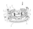
- FIG. 3is a perspective view of internal components of the IVT of FIG. 1 .
- FIG. 4is a plan view of internal components of the IVT of FIG. 1 .
- FIG. 5is an exploded view of shifting components that can be used with the IVT of FIG. 1 .
- FIG. 6is a plan view of an embodiment of first and second carrier members that can be used in the IVT of FIG. 1 .
- FIG. 7is a cross-sectional view of an infinitely variable transmission (IVT) having a skew-based control system.
- IVTinfinitely variable transmission
- FIG. 8is a cross-sectional perspective view of the IVT of FIG. 7 .
- FIG. 9is a cross-sectional view of an embodiment of a carrier driver ring that can be used with the IVT of FIG. 7 .
- FIG. 10is a perspective view of the carrier driver ring of FIG. 9 .
- FIG. 11is a cross-sectional plan view of the carrier driver ring of FIG. 9 .
- FIG. 12is a cross-sectional plan view of one embodiment of a carrier driver ring that can be used in the IVT of FIG. 7 .
- FIG. 13is a cross-sectional plan view of another embodiment of a carrier driver ring that can be used in the IVT of FIG. 7 .
- FIG. 14is a cross-sectional view of an IVT having a skew-based control system and a carrier driver ring.
- FIG. 15is a schematic view of an embodiment of an IVT having a skew-based control system and a linearly actuated carrier driver.
- FIG. 16is a cross-sectional view of one embodiment of an IVT having a skew-based control system and a linearly actuated carrier driver.
- FIG. 17is a partially cross-sectioned perspective view of certain internal shifting components of the IVT of FIG. 16 .
- FIG. 18is a plan view of the internal shifting components of FIG. 17 .
- FIG. 19is a plan view A-A of the internal shifting components of FIG. 18 .
- FIG. 20is a partially cross-sectioned perspective view of one embodiment of an IVT having a skew-based control system.
- FIG. 21is a cross-sectional view of the IVT of FIG. 20 .
- FIG. 22is an exploded, cross-sectioned view of the IVT of FIG. 20 .
- FIG. 23is an exploded view of certain internal components of the IVT of FIG. 20 .
- FIG. 24is a cross-sectional view of a torque limiter that can be used with the IVT of FIG. 20 .
- FIG. 25is an exploded view of the torque limiter of FIG. 24 .
- FIG. 26is partially cross-sectioned view of a disengagement mechanism that can be used with the IVT of FIG. 20 .
- FIG. 27is a cross-sectional view of the disengagement mechanism of FIG. 26 .
- FIG. 28is another cross-sectional view of the disengagement mechanism of FIG. 26 .
- FIG. 29is a cross-sectional view of an embodiment of a disengagement mechanism that can be used with the IVT of FIG. 1 or 20 .
- FIG. 30is another cross-sectional view of the disengagement mechanism of FIG. 29 .
- FIG. 31is a perspective view of a disengagement mechanism that can be used with the IVT of FIG. 20 .
- FIG. 32is a cross-sectional view of the disengagement mechanism of FIG. 31 .
- FIG. 33is another perspective view of the disengagement mechanism of FIG. 31 .
- FIG. 34is yet another cross-sectional view of the disengagement mechanism of FIG. 31 .
- FIG. 35is a schematic depicting a hydraulic system that can be used with the IVT of FIG. 20 .
- FIG. 36is a cross-sectional view of one embodiment of an IVT having a skew-based control system.
- FIG. 37is a plan view B-B of certain components of the IVT of FIG. 36 .
- FIG. 38is a plan view of a carrier that can be used with the IVT of FIG. 36 .
- the terms “operationally connected,” “operationally coupled”, “operationally linked”, “operably connected”, “operably coupled”, “operably linked,” and like termsrefer to a relationship (mechanical, linkage, coupling, etc.) between elements whereby operation of one element results in a corresponding, following, or simultaneous operation or actuation of a second element. It is noted that in using said terms to describe inventive embodiments, specific structures or mechanisms that link or couple the elements are typically described. However, unless otherwise specifically stated, when one of said terms is used, the term indicates that the actual linkage or coupling may take a variety of forms, which in certain instances will be readily apparent to a person of ordinary skill in the relevant technology.
- radialis used here to indicate a direction or position that is perpendicular relative to a longitudinal axis of a transmission or variator.
- axialrefers to a direction or position along an axis that is parallel to a main or longitudinal axis of a transmission or variator.
- Traction drivesusually involve the transfer of power between two elements by shear forces in a thin fluid layer trapped between the elements.
- the fluids used in these applicationsusually exhibit traction coefficients greater than conventional mineral oils.
- the traction coefficient ( ⁇ )represents the maximum available traction forces which would be available at the interfaces of the contacting components and is a measure of the maximum available drive torque.
- friction drivesgenerally relate to transferring power between two elements by frictional forces between the elements.
- the IVTs described heremay operate in both tractive and frictional applications.
- the IVTcan operate at times as a friction drive and at other times as a traction drive, depending on the torque and speed conditions present during operation.
- Embodiments of the invention disclosed hereare related to the control of a variator and/or an IVT using generally spherical planets each having a tiltable axis of rotation (sometimes referred to here as a “planet axis of rotation”) that can be adjusted to achieve a desired ratio of input speed to output speed during operation.
- adjustment of said axis of rotationinvolves angular misalignment of the planet axis in a first plane in order to achieve an angular adjustment of the planet axis of rotation in a second plane, thereby adjusting the speed ratio of the variator.
- the angular misalignment in the first planeis referred to here as “skew” or “skew angle”.
- This type of variator controlis generally described in U.S.
- a control systemcoordinates the use of a skew angle to generate forces between certain contacting components in the variator that will tilt the planet axis of rotation in the second plane.
- the tilting of the planet axis of rotationadjusts the speed ratio of the variator.
- Embodiments of skew control systems(sometimes referred to here as “skew based control systems”) and skew angle actuation devices for attaining a desired speed ratio of a variator will be discussed.
- FIG. 1shows an IVT 100 that can be used in many applications including, but not limited to, human powered vehicles (for example, bicycles), light electrical vehicles, hybrid human-, electric-, or internal combustion powered vehicles, industrial equipment, wind turbines, etc. Any technical application that requires modulation of mechanical power transfer between a power input and a power sink (for example, a load) can implement embodiments of the IVT 100 in its power train.
- human powered vehiclesfor example, bicycles
- light electrical vehiclesfor example, hybrid human-, electric-, or internal combustion powered vehicles
- industrial equipmentwind turbines, etc.
- Any technical application that requires modulation of mechanical power transfer between a power input and a power sinkfor example, a load
- a power sinkfor example, a load
- the IVT 100includes a housing 102 coupled to a housing cap 104 .
- the housing 102 and the housing cap 104support a power input interface such as a pulley 106 and a control interface such as an actuator coupling 108 .
- the pulley 106can be coupled to a drive belt driven by a source of rotational power such as an internal combustion engine (not shown).
- the IVT 100is provided with a main shaft 110 that substantially defines a longitudinal axis of the IVT 100 .
- the main shaft 110couples to the pulley 106 .
- the main shaft 110is supported by a bearing 112 in the housing cap 104 .
- the IVT 100includes a plurality of traction planet assemblies 114 arranged angularly about the main shaft 110 .
- Each traction planet assembly 114is coupled to first and second carrier members 116 , 118 , respectively.
- the main shaft 110couples to the first carrier member 116 .
- the first and second carrier members 116 , 118are coaxial with the main shaft 110 .
- each traction planet assembly 114is coupled to first and second traction rings 120 , 122 , respectively.
- Each traction planet assembly 114is in contact with an idler assembly 121 at a radially inward location.
- the first traction ring 120couples to a first axial force generator assembly 124 .
- the first traction ring 120 and the first axial force generator assembly 124is substantially non-rotatable with respect to the housing 102 .
- the first axial force generator assembly 124is coupled to a ground ring 125 .
- the ground ring 125attaches to a shoulder 123 extending from the housing cap 104 .
- the second traction ring 122is coupled to a second axial force generator 126 .
- the second traction ring 122 and the second axial force generator 126is coupled to an output power interface 128 .
- the output power interface 128can be coupled to a load (not shown).
- the output power interface 128includes a disengagement mechanism 130 configured to mechanically decouple the second traction ring 122 from the load.
- the IVT 100can be used with a shift control mechanism 140 .
- the shift control mechanism 140can be used other types of transmissions, and is shown here with the IVT 100 as an example.
- the shift control mechanism 140can include the actuator coupling 108 coupled to a rocker arm 142 .
- the rocker arm 142couples to a shift fork 144 that is configured to rotate about a pivot pin 146 .
- the pivot pin 146is offset from the longitudinal axis.
- the shift fork 144couples to a shift collar 148 .
- the shift collar 148supports a bearing 150 .
- the bearing 150couples to a carrier driver nut 152 .
- the carrier driver nut 152is coupled to the main shaft 110 and the first carrier member 116 .
- the rocker arm 142rotatably couples to a pivot 143 .
- the pivot 143can be a dowel attached to the shift fork 144 .
- the shift fork 144can have a set of slots 154 .
- the slots 154guide a set of engagement dowels 156 attached to the shift collar 148 .
- the shift collar 148is provided with four engagement dowels 156 .
- two engagement dowels 156are positioned to ride in the slots 154 while two engagement dowels 156 are positioned to ride in a set of slots 155 ( FIG. 2 ) formed in the shoulder 123 of the housing cap 104 .
- the carrier driver nut 152has an inner bore 158 formed with helical splines.
- the inner bore 158couples to mating helical splines 160 formed on the main shaft 110 .
- the carrier driver nut 152is provided with a number of guide surfaces 162 extending radially outward from the inner bore 158 .
- the guide surfaces 162couple to mating guide surfaces 164 formed on the first carrier member 116 .
- the second carrier member 118can be provided with a number of guide slots 170 arranged angularly about a central bore 171 .
- the guide slots 170are aligned with a radial construction line 76 when viewed in the plane of the page of FIG. 6 .
- the guide slots 170are adapted to receive one end of a planet axle 115 ( FIG. 1 ).
- a radially inward portion 172 of the guide slots 170are formed with curved profiles sized to accommodate the traction planet axle 115 .
- the first carrier member 116is provided with a number of radially off-set guide slots 174 arranged angularly about a central bore 175 .
- Each radially off-set guide slot 174is sized to accommodate the coupling of the first carrier member 116 to the planet axle 115 .
- the radially off-set guide slots 174are angularly offset from the radial construction line 76 when viewed in the plane of the page of FIG. 6 .
- the angular offsetcan be approximated by an angle 88 .
- the angle 88is formed between the radial construction line 76 and a construction line 90 .
- the construction line 90substantially bisects the radially off-set guide slot 174 when viewed in the plane of the page of FIG. 6 .
- the angle 88is between 3 degrees and 45 degrees.
- a low angle 88produces a highly responsive transmission ratio change but potentially more difficult to control or stabilize, while a high angle can be less responsive in transmission ratio change but easy to control by comparison.
- the angle 88can be, for example, 10 degrees. In other embodiments, where it is desirable to have slower speed, precise control of transmission ratio, the angle 88 can be about 30 degrees.
- the said values of the angle 88are provided as an illustrative example, and the angle 88 can be varied in any manner a designer desires. In some embodiments, the angle 88 can be any angle in the range of 10 to 25 degrees including any angle in between or fractions thereof.
- the angle 88can be 10, 11, 12, 13, 14, 15, 16, 17, 18, 19, 20, 21, 22, 23, 24, 25, or any portion thereof. In other embodiments, the angle 88 can be 20 degrees.
- the radially off-set guide slots 174can be arranged so that the construction line 90 is radially offset from a construction line 91 by a distance 92 .
- the construction line 91is parallel to the construction line 90 and intersects the center of the first carrier member 116 .
- a change in transmission ratiois achieved by rotating the actuator coupling 108 .
- the actuator coupling 108is attached to a user control (not shown) that can be a mechanical linkage actuated with a user's hand.
- the actuator coupling 108can be coupled to an electrical or hydraulic actuator that can impart a rotary motion to the actuator coupling 108 that is indicative of the desired transmission ratio for IVT 100 . Since the actuator coupling 108 is axially fixed with respect to the longitudinal axis, a rotation of the actuator coupling 108 tends to rotate the rocker arm 142 to thereby rotate and axially translate the pivot 143 .
- Movement of the pivot 143tends to rotate the shift fork 144 about the pivot pin 146 .
- the pivot pin 146is off-set from the main shaft 110 so that a rotation of the shift fork 144 about the pivot pin 146 corresponds to an axial translation of the slots 154 .
- the axial movement of the slots 154tends to axially move the shift collar 148 with respect to the main shaft 110 .
- the carrier driver nut 152is operably coupled to the shift collar 148 , an axial translation of the shift collar 148 corresponds to an axial translation of the carrier driver nut 152 .
- the carrier driver nut 152couples to the helical splines 160 of the main shaft 110 .
- An axial translation of the carrier driver nut 152facilitates a relative rotation of the carrier driver nut 152 with respect to the main shaft 110 . Since the carrier driver nut 152 engages the guide surfaces 164 of the first carrier member 116 , a rotation of the carrier driver nut 152 with respect to the main shaft 110 corresponds to a rotation of the first carrier member 116 with respect to the main shaft 110 . A rotation of the first carrier member 116 with respect to the second carrier member 118 tends to change the transmission ratio of the IVT 100 .
- a designercan configure the position of the rocker 142 , the pivot 143 , and the pivot pin 146 relative to the slots 154 to achieve a desired relationship between a rotation applied to the actuator coupling 108 and the axial displacement of the carrier driver nut 152 .
- a designermay select the position of the rocker 142 , the pivot 143 , and the pivot pin 146 to provide a desired force or torque applied to the actuator coupling 108 to achieve a change in transmission ratio.
- a designercan select the pitch and lead of the helical splines 160 to achieve a desired relationship between an axial displacement of the carrier driver nut 152 and a rotation of the first carrier member 116 .
- the IVT 100can be provided with a pump assembly 180 .
- the pump assembly 180includes a pump driver 182 that couples to a lobe 184 formed on the first carrier member 116 .
- the pump assembly 180includes a pump plunger 186 attached to the pump driver 182 .
- the pump plunger 186surrounds a valve body 188 and a valve plunger 190 .
- the lobe 184has a center 191 ( FIG. 6 ) that is off-set from a center 192 of the first carrier member 116 .
- the lobe 184can be formed on main shaft 110 or on a retaining nut 193 , and likewise, the pump assembly 180 is appropriately located axially so that the pump driver 182 can engage the lobe 184 .
- the main shaft 110rotates about the longitudinal axis and thereby drives the first carrier member 116 .
- the lobe 184drives the pump driver 182 in a reciprocating motion as the first carrier member 116 rotates about the longitudinal axis.
- the ground ring 125is provided with a guide groove 194 that is adapted to receive the pump driver 182 .
- the ground ring 125can also be provided with a number of clearance reliefs 196 that are appropriately sized to provide clearance to the engagement dowels 156 and the shift fork 144 .
- an IVT 200can include a number of traction planet assemblies 202 arranged angularly about a longitudinal axis 204 . For clarity, the housing and some internal components of the IVT 200 are not shown.
- Each traction planet assembly 202is provided with a ball axle 206 .
- the ball axles 206are operably coupled to first and second carrier members 208 , 210 , respectively.
- the first and second carrier members 208 , 210can be substantially similar to the first and second carrier members 116 , 118 , respectively.
- the first and second carrier members 208 , 210couple to a rotational power source (not shown).
- the IVT 200is provided with a carrier driver ring 212 located radially outward of each of the traction planet assemblies 202 .
- the carrier driver ring 212is couple to a shift clevis 214 by a set of bearings 215 .
- the bearing 215can be rotationally constrained to the carrier drive ring 212 with a plurality of dowels 217 , for example.
- the shift clevis 214is provided with a threaded bore 213 .
- the threaded bore 213is generally parallel to the longitudinal axis 204 .
- the threaded bore 213can couple to a threaded shift rod (not shown) to facilitate the axial translation of the shift clevis 214 .
- the carrier driver ring 212has a set of longitudinal grooves 220 formed on an inner circumference of the carrier driver ring 212 .
- the longitudinal grooves 220are substantially parallel to the longitudinal axis 204 .
- the carrier driver ring 212has a set of off-set longitudinal grooves 222 formed on the inner circumference.
- the off-set longitudinal grooves 222are angled with respect to the longitudinal axis 204 .
- the off-set longitudinal grooves 222form an angle 224 with respect to the longitudinal axis 204 when viewed in the plane of FIG. 9 .
- the angle 224can be any angle in the range of 0 to 30 degrees including any angle in between or fractions thereof.
- the angle 224can be 0, 1, 2, 3, 4, 5, 6, 7, 8, 9, 10, 11, 12, 13, 14, 15, 16, 17, 18, 19, 20, 21, 22, 23, 24, 25, 26, 27, 28, 29, 30 or any portion thereof.
- the first carrier member 208is provided with a number of dowels 228 .
- the dowels 228couple to, and are guided by, the longitudinal grooves 220 .
- the second carrier member 210is provided with a number of dowels 230 .
- the dowels 230couple to, and are guided by, the off-set longitudinal grooves 222 .
- a change in transmission ratiocan be achieved by axially translating the shift clevis 214 .
- An axial translation of the shift clevis 214tends to axially translate the carrier driver ring 212 .
- An axial translation of the carrier driver ring 212tends to guide the dowels 228 , 230 in the grooves 220 , 222 , respectively. Since the first and second carrier members 208 , 210 are substantially fixed in the axial direction, the first and second carrier members 208 , 210 rotate relative to each other as the dowels 228 , 230 travel axially in the grooves 220 , 222 , respectively.
- the longitudinal grooves formed on the carrier driver ring 212can take many forms in order to provide the desired relative rotation of the first carrier member 208 with respect to the second carrier member 210 .
- FIG. 11shows the longitudinal groove 220 and the off-set longitudinal groove 222 .
- the grooves 220 , 222are separated by a distance 232 .
- the grooves 220 , 222are separated by a distance 234 .
- the carrier driver ring 212is provided with the longitudinal grooves 220 and a set of curved groove 236 .
- FIG. 12shows the longitudinal grooves 220 and the off-set longitudinal groove 222 .
- the carrier driver ring 212is provided with a set of positively off-set longitudinal grooves 238 and a set of negatively off-set longitudinal grooves 240 .
- the embodiments described hereare for illustrative purposes and the shape and dimensions of the grooves formed on the carrier ring 212 can be configured by a designer to achieve a desired shift performance.
- the 232 distance between the longitudinal grooves 220 and the off-set longitudinal grooves 222can be less than the distance 234 on an opposite side of the carrier driver ring 212 .
- the difference between the distances 232 , 234can be configured to produce a desired rotation of the first carrier member 208 with respect to the second carrier member 210 over an axial displacement of the carrier driver ring 212 along the longitudinal axis 204 .
- an IVT 300can be substantially similar to the IVT 200 .
- the IVT 300can include a housing 302 configured to substantially enclose internal components of the IVT 300 .
- the IVT 300can be provided with a carrier driver ring 304 .
- the carrier driver ring 304can be coupled to the first and second carrier members 208 , 210 in a similar manner as the carrier driver ring 212 .
- the carrier driver ring 304can be configured to translate axially by an actuator such as a motor (not shown).
- the carrier driver ring 304is radially supported on an output ring 306 .
- the output ring 306is operably coupled to each of the traction planet assemblies 202 .
- an IVT 400can have a number of traction planet assemblies 402 arranged angularly about a main shaft 404 .
- Each traction planet assembly 402couples to first and second traction rings 406 , 408 , respectively.
- Each traction planet assembly 402couples to an idler assembly 410 .
- the idler assembly 410is located radially inward of each traction planet assembly 402 .
- each traction planet assembly 402is coupled to first and second carrier members 412 , 414 .
- the first and second carrier members 412 , 414can be substantially similar to the first and second carrier members 116 , 118 , respectively.
- the first carrier member 412is rigidly attached to the main shaft 404 .
- the first and second carrier members 412 , 414 and the main shaft 404can be adapted to operably couple to a source for rotational power (not shown).
- the second carrier member 414is adapted to rotate with respect to the first carrier member 412 .
- the second carrier 414is coupled to a torsion plate 416 .
- the torsion plate 416is coaxial with the second carrier 414 and can be rigidly attached to the second carrier plate 414 with splines, weld, or other appropriate fastening means.
- the torsion plate 416is rigid or stiff in a rotational direction but has a degree of flexibility in the axial direction, as is common among torsion plates.
- the torsion plate 416is coupled to a carrier driver nut 418 at a radially inward location.
- the carrier driver nut 418has an inner bore formed with helical splines 420 that are arranged to engage mating helical splines formed on the main shaft 404 .
- the carrier driver nut 418is operably coupled to an actuator coupling 422 .
- the actuator coupling 422is coupled to a linear actuator such as a servo motor or manual lever (not shown) that produces a force depicted as a vector 424 in FIG. 15 .
- the actuator coupling 422is substantially non-rotatable about the main shaft 404 .
- a change in transmission ratiois achieved by axially translating actuator coupling 422 .
- An axial translation of the actuator coupling 422tends to axially translate the carrier driver nut 418 .
- the carrier driver nut 418engages the main shaft 404 on helical splines 420
- an axial translation of the carrier driver nut 418 with respect to the main shaft 404tends to facilitate a relative rotation between the carrier driver nut 418 and the main shaft 404 .
- the torsion plate 416rotates as the carrier driver nut 418 rotates, which tends to rotate the second carrier member 414 with respect to the first carrier member 412 .
- an IVT 500can be provided with a number of traction planet assemblies 502 in contact with, and radially outward of an idler assembly 504 .
- Each traction planet assembly 502is in contact with first and second traction rings 506 , 508 , respectively.
- the first traction ring 506is substantially non-rotatable.
- the IVT 500can be provided with an output shaft 510 .
- the output shaft 510couples to a common axial force generator coupling 512 , which is configured to engage the second traction ring 508 .
- Each traction planet assembly 502is guided and supported by first and second carrier members 514 , 516 , respectively.
- the first and second carrier members 514 , 516are provided with guide slots 513 , 515 , respectively.
- the guide slots 513 , 515are substantially similar to guide slots 170 , 174 , respectively.
- the first and second carrier members 514 , 516are adapted to receive a power input from a rotational power source (not shown).
- an input shaft 518can be coupled to a drive gear 520 that engages a carrier gear 522 .
- the carrier gear 522facilitates the transfer of power to the first and second carrier members 514 , 516 .
- the output shaft 510can be supported by a bearing, for example, on the housing 524 .
- the housing 524is formed with two parts that are fastened together to substantially enclose the internal components of the IVT 500 .
- the IVT 500is provided with a center shaft 526 that substantially defines a longitudinal axis of the IVT 500 .
- the center shaft 526can be configured to support the first and second carrier members 514 , 516 .
- the second carrier member 516is rigidly attached to the center shaft 526 .
- the first carrier member 514can be piloted onto the center shaft 526 so that the first carrier member 514 can rotate with respect to the second carrier member 516 .
- One end of the center shaft 526can be configured to support an actuator coupling 528 .
- a bearing 529supports the actuator coupling 528 on the center shaft 514 .
- the bearing 529is configured to allow axial translation of the actuator coupling 528 with respect to the center shaft 526 .
- the actuator coupling 528is attached to the housing 524 with splines and is substantially non-rotatable with respect to the center shaft 526 .
- the actuator coupling 528is coupled to a linear actuator (not shown) to facilitate an axial translation of the actuator coupling 528 .
- the actuator coupling 528couples with a bearing 530 to a carrier driver hub 532 .
- the carrier driver hub 532couples to the first and second carrier members 514 , 516 .
- the carrier driver hub 532can be provided with a number of rods 534 extending from a substantially cylindrical body.
- Each of the rods 534is provided with a roller 536 .
- the rods 534engage a number of longitudinal slots 538 formed on the second carrier member 516 .
- the rollers 536engage a number of longitudinal slots 540 formed on the first carrier member 514 .
- the longitudinal slots 538are substantially parallel with the longitudinal axis of IVT 500 .
- the longitudinal slots 540are angled with respect to the longitudinal axis of IVT 500 when viewed in the plane of the page of FIG. 19 .
- an IVT 600includes a housing 602 coupled to a housing cap 604 .
- the housing 602 and the housing cap 604support a power input interface such as a pulley 606 and a shift actuator 608 .
- the pulley 606can be coupled to a drive belt driven by a source of rotational power such as an internal combustion engine (not shown).
- the IVT 600is provided with a main shaft 610 that substantially defines a longitudinal axis of the IVT 600 .
- the main shaft 610couples to the pulley 606 .
- the IVT 600includes a plurality of traction planet assemblies 614 coupled to first and second carrier members 616 , 618 , respectively.
- the first and second carrier members 616 , 618are provided with guide slots that are substantially similar to the guide slots 170 and the radially offset guide slots 174 .
- the first and second carrier members 616 , 618have a thin and substantially uniform cross-section when viewed in the plane of the page of FIG. 21 , which allows various manufacturing techniques, such as sheet metal stamping, to be employed in the manufacture of the first and second carrier members 616 , 618 .
- the main shaft 610couples to the first carrier member 616 .
- Each traction planet assembly 614is in contact with first and second traction rings 620 , 622 , respectively.
- Each traction planet assembly 614is in contact with an idler assembly 621 at a radially inward location.
- the second traction ring 622couples to an axial force generator 624 .
- the axial force generator 624couples to an output driver 626 .
- the first traction ring 620couples to a ground ring 625 and is substantially non-rotatable with respect to the housing 602 .
- the IVT 600has an output shaft 627 coupled to the output driver 626 .
- the output shaft 627delivers a rotational power from the IVT 600 .
- the output shaft 627is supported in the housing 602 by an angular contact bearing 628 and a radial ball bearing 629 (see for example, FIG. 23 ).
- a shaft seal 631can be coupled to the output shaft 627 and the housing 602 .
- the IVT 600can be provided with a torque limiter 630 that couples to the second carrier member 618 and the main shaft 610 .
- the IVT 600can also be provided with a pump assembly 635 coupled to the main shaft 610 (see for example, FIG. 22 ).
- the pump assembly 635can use a gerotor type pump to pressurize transmission fluid and distribute it to internal components of the IVT 600 .
- the pump assembly 635can be appropriately equipped with hoses and/or lines to route transmission fluid. During operation of the IVT 600 , the pump assembly 635 is driven by the main shaft 610 .
- the IVT 600is provided with a shift control mechanism 640 .
- the shift control mechanism 640can be used on other types of transmission and is shown here with the IVT 600 as an example.
- the shift control mechanism 640can include an actuator linkage 642 coupled to the shift actuator 608 .
- the shift actuator 608can be coupled to a shift fork 644 .
- the shift actuator 608is configured to pivot the shift fork 644 about an axis 646 .
- the axis 646is offset from the longitudinal axis of the IVT 600 .
- the shift fork 644can be supported in the housing cap 604 .
- the shift fork 644can be coupled to a shift collar 648 .
- the shift collar 648supports a bearing 650 .
- the shift fork 644 and the shift collar 648can be coupled, for example, with pins 651 .
- the shift fork 644 and the shift collar 648are substantially non-rotatable about the longitudinal axis of the IVT 600 .
- the shift control mechanism 640includes a carrier driver nut 652 .
- the carrier driver nut 652couples to the main shaft 610 through a set of helical splines 654 .
- the carrier driver nut 652couples to the first carrier member 616 through a carrier extension 656 .
- the carrier extension 656has a set of axial guide slots that are configured to engage the carrier driver nut 652 .
- a shift in the transmission ratiocan be achieved by moving the actuator linkage 642 to thereby rotate the shift actuator 608 .
- a rotation of the shift actuator 608corresponds to pivoting of the shift fork 644 about the axis 646 .
- the pivoting of the shift fork 644urges the shift collar 648 axially with respect to the main shaft 610 .
- the shift collar 648thereby axially translates the bearing 650 and carrier driver nut 652 .
- the helical splines 654tend to rotate the carrier driver nut 652 as the carrier driver nut 652 moves axially.
- the rotation of the carrier driver nut 652is typically a small angle.
- the carrier extension 656and consequently the first carrier member 616 , is guided through a rotation by the carrier driver nut 652 . As explained previously in reference to FIG. 6 , a rotation of the first carrier member 616 with respect to the second carrier member 618 causes a shift in the transmission ratio of the IVT 600 .
- the helical splines 654have a lead in the range of 200-1000 mm.
- the leadis in the range of 400-800 mm.
- the leadis related to how much friction is in the system that can counteract a phenomenon known as back torque shifting.
- the leadcan be sized to reduce the input force on the carrier driver nut 652 , the required rotation of the first carrier member 616 to shift through the ratio, and available package space. The sizing of the lead is subject to design requirements, and could also be impacted by testing results.
- the IVT 600can be provided with a torque limiter 630 coupled to the second carrier member 618 .
- the torque limiter 630can be used with other types of transmissions and is shown here with the IVT 600 as an example.
- the second carrier member 618is provided with a piloting shoulder 660 that is configured to pilot to the main shaft 610 .
- the second carrier member 618has a number of openings 662 arranged radially about the piloting shoulder 660 .
- the openings 662are sized appropriately to couple to a plurality of springs 664 .
- the springs 664are coil springs having end caps 666 .
- the torque limiter 630includes a spring carrier 668 .
- the springs 664are coupled to the spring carrier 668 .
- a number of retaining dowels 670are provided on the spring carrier 668 to mate with each end cap 666 in order to facilitate retaining the springs 664 on the spring carrier 668 .
- the spring carrier 668couples to the main shaft 610 with a splined inner bore 672 .
- the torque limiter 630includes a carrier cap 676 coupled to the second carrier member 618 .
- the spring carrier 668is axially located between the second carrier member 618 and the carrier cap 676 .
- the carrier cap 676can be provided with a number of tabs 678 to facilitate attachment to the second carrier member 618 with, for example, rivets 679 .
- the carrier cap 676can be provided with a number of openings 680 arranged radially about a piloting shoulder 682 . In one embodiment, the piloting shoulder 682 cooperates with a mating shoulder 684 formed on the spring carrier 668 .
- torquecan be limited to a predetermined value by using the torque limiter 630 .
- the main shaft 610is adapted to receive a rotational power from the pulley 606 .
- the rotational poweris transferred to the first carrier member 616 and the spring carrier 668 .
- the spring carrier 668transfers the rotational power to the second carrier member 618 via the springs 664 .
- the springs 664are sized appropriately so that the springs 664 deflect when an output torque is above a predetermined value or in the case when a torque on the second carrier member 618 is above a predetermined value.
- the deflection of springs 664corresponds to a rotation of the second carrier member 618 with respect to the first carrier member 616 thereby shifting the transmission ratio.
- the shift in transmission ratioreduces the torque on the second carrier member 618 .
- the IVT 600can be provided with a disengagement mechanism 700 .
- the disengagement mechanism 700can be used with other types of transmissions and is shown here with the IVT 600 as an example.
- the disengagement mechanism 700includes a outer ring 702 coupled to a coupling ring 704 .
- the coupling ring 704is attached to the traction ring 620 .
- the outer ring 702 and the coupling ring 704replace the ground ring 625 .
- the outer ring 702couples to the housing 602 and housing cap 604 .
- an actuator(not shown) couples to the outer ring 702 .
- the actuatorcan be a lever (not shown) that extends through the housing 602 to thereby enable the outer ring 702 to be rotated.
- the outer ring 702is provided with a number of ramps 706 about the inner circumference.
- the ramps 706couple to a set of splines 708 formed on the outer periphery of the inner ring 704 .
- decoupling of the input from the outputcan be achieved by rotating the outer ring 706 .
- the rotation of the outer ring 706corresponds to an axial displacement of the traction ring 620 from the traction planet assemblies 614 .
- the IVT 600can be provided with a disengagement mechanism 800 .
- the disengagement mechanism 800can be used with other types of transmissions and is shown here with the IVT 600 as an example.
- the disengagement mechanism 800has a drive shaft 802 that can be selectively coupled to an output shaft 804 using a coupling 806 . Once assembled the drive shaft 802 and the output shaft 804 can be used in place of the output shaft 627 .
- the coupling 806is configured to engage a set of splines 808 formed on an inner diameter of the output shaft 804 .
- a spring(not shown) can be inserted between the coupling and the output shaft 804 .
- the springtends to bias the coupling 806 to the position depicted in FIG. 29 , which is an engaged position.
- the coupling 806is attached to a cable pull 810 .
- the cable pull 810can be supported on an internal bore of the coupling 806 by a bearing 812 .
- the cable pull 810can be attached to a push-pull cable (not shown).
- the cablecan be coupled to an external linkage that can be actuated to tension the cable and move the coupling 806 axially.
- a cable guide 814provides a path through which the cable can enter the inner bore of the output shaft 814 without interference.
- the cable guide 814is supported with a bearing 816 .
- the output shaft 804can be selectively coupled to an engaged position, as illustrated in FIG. 30 , by tensioning the cable (not shown) and axially translating the coupling 806 .
- the IVT 600can be provided with a disengagement mechanism 900 .
- the disengagement mechanism 900can be used with other types of transmissions and is shown here with the IVT 600 as an example.
- the disengagement mechanism 900can replace the output shaft 627 .
- the disengagement mechanism 900can include an elongated shaft 902 suitably configured to be supported in the housing 602 by bearings 628 , 629 and seal 630 .
- the elongated shaft 902can have a first end 901 and a second end 903 .
- the first end 901can be adapted to couple to an output load with, for example, a keyway or other fastening means.
- the second end 903 of the shaft 902is provided with a number of retractable teeth 904 .
- the retractable teeth 904are positioned radially about the circumference of the end 903 .
- the retractable teeth 904can be inserted between, and retained by axial extensions 906 formed on the end 903 .
- the retractable teeth 904are operably coupled to a sliding member 908 .
- the sliding member 908is coupled to an actuator coupling 910 .
- the sliding member 908guides the retractable teeth 904 to either an engaged position or a disengaged position.
- the retractable teeth can 904can be coupled to a spring member (not shown) that is configured to bias the retractable teeth 904 to a position depicted in FIGS. 31 and 32 .
- the retractable teeth 904can engage, for example, the output driver 626 .
- An actuator(not shown) can be configured to couple to the actuator coupling 910 through an inner bore of the shaft 902 to facilitate movement of the sliding member 908 and correspondingly move the teeth 904 to a second position depicted in FIGS. 33 and 34 . In said position, the teeth 904 are displaced radially so that the output driver 626 is decoupled from the shaft 902 .
- a hydraulic system 950can be used with the IVT 100 , the IVT 600 , or other embodiments of transmissions.
- the hydraulic system 950includes a sump 952 having a fill depth 954 .
- the sump 952is formed into a lower portion of the housing 602 , for example.
- rotating components of the IVT 600are depicted as rotating components 955 in FIG. 35 .
- the hydraulic system 950includes a pump 956 that can be substantially similar to the pump assembly 635 , for example.
- the pump 956transports fluid from the sump 952 to a reservoir 958 .
- the reservoir 958is provided with a first orifice 960 and a second orifice 962 .
- the first orifice 960is positioned above the second orifice 960 .
- the reservoir 958is located above the rotating components 955 and the sump 952 .
- the reservoir 958can be formed on the housing 602 , for example. In other embodiments, the reservoir 958 is attached to the outside of the housing 602 and configured to have fluid communication with the rotating components 958 and the sump 952 .
- a fluidis added to the sump 952 .
- the volume of the sump 952can be small, therefore variation in the fluid volume added to the sump 952 can have a significant influence on the fill depth 954 .
- the fill depth 954can be high enough to cause fluid in the sump 952 to contact the rotating components 955 . Contact between the fluid in the sump 952 and the rotating components 955 can create drag and windage, which are known to be problematic.
- increasing the volume of fluidmay improve thermal characteristics, durability, and maintenance. Therefore, the hydraulic system 952 can be implemented to facilitate the increase in fluid volume added to the sump 952 and maintain a fill depth 954 below the rotating components 955 .
- fluidis drawn from the sump 952 by the pump 956 , which lowers the fill depth 954 .
- the fluidis pressurized and delivered by the pump 956 to the reservoir 958 .
- the reservoir 958receives pressurized fluid and fills the volume of the reservoir 958 .
- the first and second orifices 960 , 962are sized appropriately so that once the reservoir 958 is under pressure, fluid can flow from the first orifice 960 while substantially no fluid flows from the second orifice 962 .
- the second orifice 962can be a check valve that is configured to be open when the reservoir 958 is depressurized, and closed when the reservoir 958 is pressurized.
- the fluid flow from the first orifice 960is directed to the rotating components 955 to provide lubrication and cooling.
- the reservoir 958accumulates a volume of fluid. Once operation of the IVT 600 ceases, the accumulated volume drains from the reservoir 958 and returns to the sump 952 .
- an IVT 1000can be substantially similar to the IVT 100 .
- the IVT 1000includes a number of balls 1001 arranged angularly about a longitudinal axis 1002 .
- Each ball 1001is configured to rotate about an axle 1003 that forms a tiltable axis.
- One end of the axle 1003is provided with a spherical roller 1004 .
- An opposite end of the axle 1003is coupled to a guide block 1005 with, for example, a pin 1010 .
- the guide block 1005has an extension 1006 .
- the IVT 1000can include a first carrier member 1007 that is substantially similar to the carrier member 118 .
- the first carrier member 1007is configured to couple to the spherical rollers 1004 to provide the axles 1003 with a suitable degree of freedom.
- the IVT 1000can include a second carrier member 1008 that is configured to operably couple to the guide blocks 1005 .
- the IVT 100is provided with a shifting plate 1012 arranged coaxially with the first and second carrier members 1007 , 1008 .
- the shifting plate 1012couples to the extensions 1006 .
- the shifting plate 1012can be actuated with, for example, the shift control mechanism 140 .
- the shifting plate 1012is configured to rotate relative to the first and second carrier members 1007 , 1008 .
- the shifting plate 1012is provided with a number of slots 1014 .
- the extensions 1006couple to the slots 1014 .
- the slot 1014can be illustrated as having three portions: a first portion 1015 , a middle portion 1016 , and a third portion 1017 .
- the middle portion 1016can be defined as the arc length between a set of radial construction lines 1018 , 1019 , respectively.
- the first portion 1015 and the third portion 1017are angularly off-set from the radial construction lines 1018 , 1019 , respectively, in a substantially similar way as the radially off-set slots guide slots 174 are offset from the radial construction line 76 .
- a change in transmission ratiocan be achieved by rotating the shifting plate 1012 with respect to the first and second carrier members 1007 , 1008 .
- the extensions 1006are guided by the slots 1014 .
- the transmission ratiocan be a forward or positive ratio.
- the transmission ratiocan be a reverse or negative ratio.
- the transmission ratiois in neutral or a condition referred to as “powered-zero.”
- the dimensions of the slot 1014can be appropriately sized to accommodate a desired relationship between a change in the transmission ratio and a change in, for example, a change in an actuator position.
Landscapes
- Engineering & Computer Science (AREA)
- General Engineering & Computer Science (AREA)
- Mechanical Engineering (AREA)
- Chemical & Material Sciences (AREA)
- Combustion & Propulsion (AREA)
- Transportation (AREA)
- Friction Gearing (AREA)
- Transmission Devices (AREA)
- Gear-Shifting Mechanisms (AREA)
- Retarders (AREA)
Abstract
Description
Claims (20)
Priority Applications (5)
| Application Number | Priority Date | Filing Date | Title |
|---|---|---|---|
| US13/035,683US8512195B2 (en) | 2010-03-03 | 2011-02-25 | Infinitely variable transmissions, continuously variable transmissions, methods, assemblies, subassemblies, and components therefor |
| US13/970,035US8721485B2 (en) | 2010-03-03 | 2013-08-19 | Infinitely variable transmissions, continuously variable transmissions, methods, assemblies, subassemblies, and components therefor |
| US14/274,043US9360089B2 (en) | 2010-03-03 | 2014-05-09 | Infinitely variable transmissions, continuously variable transmissions, methods, assemblies, subassemblies, and components therefor |
| US15/172,668US10066712B2 (en) | 2010-03-03 | 2016-06-03 | Infinitely variable transmissions, continuously variable transmissions, methods, assemblies, subassemblies, and components therefor |
| US16/120,024US20180372192A1 (en) | 2010-03-03 | 2018-08-31 | Infinitely variable transmissions, continuously variable transmissions, methods, assemblies, subassemblies, and components therefor |
Applications Claiming Priority (2)
| Application Number | Priority Date | Filing Date | Title |
|---|---|---|---|
| US31022410P | 2010-03-03 | 2010-03-03 | |
| US13/035,683US8512195B2 (en) | 2010-03-03 | 2011-02-25 | Infinitely variable transmissions, continuously variable transmissions, methods, assemblies, subassemblies, and components therefor |
Related Child Applications (1)
| Application Number | Title | Priority Date | Filing Date |
|---|---|---|---|
| US13/970,035ContinuationUS8721485B2 (en) | 2010-03-03 | 2013-08-19 | Infinitely variable transmissions, continuously variable transmissions, methods, assemblies, subassemblies, and components therefor |
Publications (2)
| Publication Number | Publication Date |
|---|---|
| US20110218072A1 US20110218072A1 (en) | 2011-09-08 |
| US8512195B2true US8512195B2 (en) | 2013-08-20 |
Family
ID=43974808
Family Applications (5)
| Application Number | Title | Priority Date | Filing Date |
|---|---|---|---|
| US13/035,683Active2031-12-11US8512195B2 (en) | 2010-03-03 | 2011-02-25 | Infinitely variable transmissions, continuously variable transmissions, methods, assemblies, subassemblies, and components therefor |
| US13/970,035ActiveUS8721485B2 (en) | 2010-03-03 | 2013-08-19 | Infinitely variable transmissions, continuously variable transmissions, methods, assemblies, subassemblies, and components therefor |
| US14/274,043ActiveUS9360089B2 (en) | 2010-03-03 | 2014-05-09 | Infinitely variable transmissions, continuously variable transmissions, methods, assemblies, subassemblies, and components therefor |
| US15/172,668Active2031-07-13US10066712B2 (en) | 2010-03-03 | 2016-06-03 | Infinitely variable transmissions, continuously variable transmissions, methods, assemblies, subassemblies, and components therefor |
| US16/120,024AbandonedUS20180372192A1 (en) | 2010-03-03 | 2018-08-31 | Infinitely variable transmissions, continuously variable transmissions, methods, assemblies, subassemblies, and components therefor |
Family Applications After (4)
| Application Number | Title | Priority Date | Filing Date |
|---|---|---|---|
| US13/970,035ActiveUS8721485B2 (en) | 2010-03-03 | 2013-08-19 | Infinitely variable transmissions, continuously variable transmissions, methods, assemblies, subassemblies, and components therefor |
| US14/274,043ActiveUS9360089B2 (en) | 2010-03-03 | 2014-05-09 | Infinitely variable transmissions, continuously variable transmissions, methods, assemblies, subassemblies, and components therefor |
| US15/172,668Active2031-07-13US10066712B2 (en) | 2010-03-03 | 2016-06-03 | Infinitely variable transmissions, continuously variable transmissions, methods, assemblies, subassemblies, and components therefor |
| US16/120,024AbandonedUS20180372192A1 (en) | 2010-03-03 | 2018-08-31 | Infinitely variable transmissions, continuously variable transmissions, methods, assemblies, subassemblies, and components therefor |
Country Status (12)
| Country | Link |
|---|---|
| US (5) | US8512195B2 (en) |
| EP (2) | EP2542800B1 (en) |
| JP (2) | JP5819863B2 (en) |
| KR (3) | KR101906331B1 (en) |
| CN (2) | CN102869900B (en) |
| BR (1) | BR112012022240A8 (en) |
| CA (1) | CA2791307C (en) |
| MX (1) | MX2012010016A (en) |
| PL (1) | PL3021004T3 (en) |
| RU (1) | RU2584635C2 (en) |
| TW (3) | TWI622520B (en) |
| WO (1) | WO2011109444A1 (en) |
Cited By (42)
| Publication number | Priority date | Publication date | Assignee | Title |
|---|---|---|---|---|
| US20120115667A1 (en)* | 2010-11-10 | 2012-05-10 | Fallbrook Technologies Inc. | Continuously variable transmission |
| US20130139531A1 (en)* | 2011-10-03 | 2013-06-06 | Fallbrook Intellectual Property Company Llc | Refrigeration system having a continuously variable transmission |
| US20130294825A1 (en)* | 2012-05-02 | 2013-11-07 | Parker-Hannifin Corporation | Spline connection |
| US20130310214A1 (en)* | 2008-10-14 | 2013-11-21 | Fallbrook Intellectual Property Company Llc | Continuously variable transmission |
| US20130331218A1 (en)* | 2010-03-03 | 2013-12-12 | Fallbrook Intellectual Property Company Llc | Infinitely variable transmissions, continuously variable transmissions, methods, assemblies, subassemblies, and components therefor |
| US20140094339A1 (en)* | 2011-06-10 | 2014-04-03 | Toyota Jidosha Kabushiki Kaisha | Continuously variable transmission |
| US8790214B2 (en)* | 2008-06-06 | 2014-07-29 | Fallbrook Intellectual Property Company Llc | Infinitely variable transmissions, continuously variable transmissions, methods, assemblies, subassemblies, and components therefor |
| US8920285B2 (en) | 2004-10-05 | 2014-12-30 | Fallbrook Intellectual Property Company Llc | Continuously variable transmission |
| US9022889B2 (en) | 2005-10-28 | 2015-05-05 | Fallbrook Intellectual Property Company Llc | Electromotive drives |
| US9046158B2 (en) | 2003-02-28 | 2015-06-02 | Fallbrook Intellectual Property Company Llc | Continuously variable transmission |
| US9074674B2 (en) | 2008-06-23 | 2015-07-07 | Fallbrook Intellectual Property Company Llc | Continuously variable transmission |
| US9182018B2 (en) | 2008-02-29 | 2015-11-10 | Fallbrook Intellectual Property Company Llc | Continuously and/or infinitely variable transmissions and methods therefor |
| US9239099B2 (en) | 2007-02-16 | 2016-01-19 | Fallbrook Intellectual Property Company Llc | Infinitely variable transmissions, continuously variable transmissions, methods, assemblies, subassemblies, and components therefor |
| US9249880B2 (en) | 2007-12-21 | 2016-02-02 | Fallbrook Intellectual Property Company Llc | Automatic transmissions and methods therefor |
| US9279482B2 (en) | 2009-04-16 | 2016-03-08 | Fallbrook Intellectual Property Company Llc | Continuously variable transmission |
| US9328807B2 (en) | 2007-02-01 | 2016-05-03 | Fallbrook Intellectual Property Company Llc | Systems and methods for control of transmission and/or prime mover |
| US9341246B2 (en) | 2005-11-22 | 2016-05-17 | Fallbrook Intellectual Property Company Llc | Continuously variable transmission |
| US9365203B2 (en) | 2008-08-05 | 2016-06-14 | Fallbrook Intellectual Property Company Llc | Systems and methods for control of transmission and/or prime mover |
| US9574643B2 (en) | 2007-04-24 | 2017-02-21 | Fallbrook Intellectual Property Company Llc | Electric traction drives |
| US9611921B2 (en) | 2012-01-23 | 2017-04-04 | Fallbrook Intellectual Property Company Llc | Infinitely variable transmissions, continuously variable transmissions, methods, assemblies, subassemblies, and components therefor |
| US9618100B2 (en) | 2008-05-07 | 2017-04-11 | Fallbrook Intellectual Property Company Llc | Assemblies and methods for clamping force generation |
| US9677650B2 (en) | 2013-04-19 | 2017-06-13 | Fallbrook Intellectual Property Company Llc | Continuously variable transmission |
| US9726282B2 (en) | 2006-06-26 | 2017-08-08 | Fallbrook Intellectual Property Company Llc | Continuously variable transmission |
| US9765862B2 (en)* | 2015-08-07 | 2017-09-19 | Kabushiki Kaisha F.C.C. | Continuously variable transmission |
| US9869388B2 (en) | 2007-07-05 | 2018-01-16 | Fallbrook Intellectual Property Company Llc | Continuously variable transmission |
| US9903450B2 (en) | 2008-08-26 | 2018-02-27 | Fallbrook Intellectual Property Company Llc | Continuously variable transmission |
| US9945456B2 (en) | 2007-06-11 | 2018-04-17 | Fallbrook Intellectual Property Company Llc | Continuously variable transmission |
| US10047861B2 (en) | 2016-01-15 | 2018-08-14 | Fallbrook Intellectual Property Company Llc | Systems and methods for controlling rollback in continuously variable transmissions |
| US10100927B2 (en) | 2007-11-16 | 2018-10-16 | Fallbrook Intellectual Property Company Llc | Controller for variable transmission |
| US10208840B2 (en) | 2005-12-09 | 2019-02-19 | Fallbrook Intellectual Property Company Llc | Continuously variable transmission |
| US10260607B2 (en) | 2007-02-12 | 2019-04-16 | Fallbrook Intellectual Property Company Llc | Continuously variable transmissions and methods therefor |
| US10400872B2 (en) | 2015-03-31 | 2019-09-03 | Fallbrook Intellectual Property Company Llc | Balanced split sun assemblies with integrated differential mechanisms, and variators and drive trains including balanced split sun assemblies |
| US10458526B2 (en) | 2016-03-18 | 2019-10-29 | Fallbrook Intellectual Property Company Llc | Continuously variable transmissions, systems and methods |
| US10495197B2 (en)* | 2017-02-07 | 2019-12-03 | Motive Power Industry Co., Ltd. | Continuously variable transmission ring driving mechanism |
| US10859142B2 (en) | 2017-11-02 | 2020-12-08 | Stephen Douglas Williams | Slip-modulated proprioceptive infinitely variable transmission and robotic power distribution system |
| US11174922B2 (en) | 2019-02-26 | 2021-11-16 | Fallbrook Intellectual Property Company Llc | Reversible variable drives and systems and methods for control in forward and reverse directions |
| US11215268B2 (en) | 2018-11-06 | 2022-01-04 | Fallbrook Intellectual Property Company Llc | Continuously variable transmissions, synchronous shifting, twin countershafts and methods for control of same |
| US11486470B2 (en) | 2020-02-04 | 2022-11-01 | Dana Heavy Vehicle Systems Group, Llc | Methods and systems for an actuation system |
| US11598397B2 (en) | 2005-12-30 | 2023-03-07 | Fallbrook Intellectual Property Company Llc | Continuously variable gear transmission |
| US11667351B2 (en) | 2016-05-11 | 2023-06-06 | Fallbrook Intellectual Property Company Llc | Systems and methods for automatic configuration and automatic calibration of continuously variable transmissions and bicycles having continuously variable transmission |
| US12013014B2 (en) | 2020-03-12 | 2024-06-18 | Sumitomo Heavy Industries, Ltd. | Friction transmission device |
| US12442434B2 (en) | 2024-06-04 | 2025-10-14 | Enviolo B.V. | Reversible variable drives and systems and methods for control in forward and reverse directions |
Families Citing this family (22)
| Publication number | Priority date | Publication date | Assignee | Title |
|---|---|---|---|---|
| US7882762B2 (en) | 2006-01-30 | 2011-02-08 | Fallbrook Technologies Inc. | System for manipulating a continuously variable transmission |
| PL2089642T3 (en) | 2006-11-08 | 2013-09-30 | Fallbrook Ip Co Llc | Clamping force generator |
| US9464701B2 (en)* | 2009-01-22 | 2016-10-11 | Orbital Traction, Ltd. | Fluid movement systems including a continuously variable transmission |
| AU2012240435B2 (en) | 2011-04-04 | 2016-04-28 | Fallbrook Intellectual Property Company Llc | Auxiliary power unit having a continuously variable transmission |
| US20140219598A1 (en)* | 2012-10-02 | 2014-08-07 | Andrew P. Grosskopf | Variable frequency generator input shaft bearing |
| US9429217B2 (en) | 2013-01-28 | 2016-08-30 | Robert Hornblower Meyer | Continuously variable drive mechanism |
| WO2014142822A1 (en)* | 2013-03-13 | 2014-09-18 | Allison Transmission Inc. | Final drive disconnect mechanism |
| US9322461B2 (en)* | 2013-03-14 | 2016-04-26 | Team Industries, Inc. | Continuously variable transmission with input/output planetary ratio assembly |
| US10012304B2 (en)* | 2013-05-07 | 2018-07-03 | Transmission Cvtcorp Inc. | Continuously variable transmission provided with a gerotor pump |
| CN103600805B (en)* | 2013-10-28 | 2016-02-24 | 南通雷圣特种电机有限公司 | The dynamic structure of novel assisted electric bicycle |
| DE102014221514A1 (en)* | 2014-10-23 | 2016-04-28 | Robert Bosch Gmbh | Adjustable friction-ring gearbox for a motor-powered and / or pedal-operated vehicle |
| WO2016148721A1 (en)* | 2015-03-19 | 2016-09-22 | Allison Transmission, Inc. | Variator stator functional and manufacturing improvements |
| CN105276110B (en)* | 2015-07-29 | 2017-05-31 | 四川大学 | One kind is without the towed buncher that spins |
| CN105114620B (en)* | 2015-09-18 | 2017-05-10 | 湖南农业大学 | A shift control device for a continuously variable transmission |
| EP3187751B1 (en)* | 2015-12-30 | 2019-03-06 | Rolless GmbH | Infinitely adjustable planetary gear |
| WO2017151610A1 (en)* | 2016-03-01 | 2017-09-08 | Dana Limited | Carrier skew shift actuator mechanism for a continuously variable ball planetary transmission having a rotataing carrier |
| JP6773297B2 (en)* | 2016-10-14 | 2020-10-21 | 日本電産シンポ株式会社 | Continuously variable transmission and bicycle |
| TWI648494B (en)* | 2017-02-07 | 2019-01-21 | 摩特動力工業股份有限公司 | Stepless speed change mechanism |
| WO2018187424A1 (en)* | 2017-04-05 | 2018-10-11 | Dana Limited | Passive ratio control methods for a ball-type planetary transmission |
| TWI648491B (en)* | 2017-11-21 | 2019-01-21 | 摩特動力工業股份有限公司 | Coaxial electric power stepless transmission |
| CN111219446B (en)* | 2018-11-27 | 2023-01-17 | 富田电机股份有限公司 | Integrated power module of electric locomotive |
| CN111559458A (en)* | 2020-05-08 | 2020-08-21 | 江苏创斯达科技有限公司 | Rear wheel driving device of power-assisted bicycle |
Citations (332)
| Publication number | Priority date | Publication date | Assignee | Title |
|---|---|---|---|---|
| US719595A (en) | 1901-07-06 | 1903-02-03 | Jacob B Huss | Bicycle driving mechanism. |
| US1121210A (en) | 1914-12-15 | Fried Krupp Germaniawerft Ag | Submarine boat. | |
| US1175677A (en) | 1914-10-24 | 1916-03-14 | Roderick Mcclure | Power-transmitting device. |
| US1207985A (en) | 1914-08-17 | 1916-12-12 | Charles I Null | Antifriction-hanger. |
| US1380006A (en) | 1917-08-04 | 1921-05-31 | Hamilton Beach Mfg Co | Variable-speed transmission |
| US1390971A (en) | 1921-01-24 | 1921-09-13 | Samain Pierre | Gearing |
| US1558222A (en) | 1924-01-14 | 1925-10-20 | Beetow Albert | Backlash take-up for gears |
| CH118064A (en) | 1924-08-07 | 1926-12-16 | Jakob Arter | Friction change transmission. |
| FR620375A (en) | 1926-06-24 | 1927-04-21 | Automatic pressure device for friction plates | |
| US1629902A (en) | 1924-08-07 | 1927-05-24 | Arter Jakob | Power-transmitting device |
| US1686446A (en) | 1926-04-15 | 1928-10-02 | John A Gilman | Planetary transmission mechanism |
| DE498701C (en) | 1927-11-18 | 1930-05-31 | Jakob Arter | Friction ball change gear |
| US1774254A (en) | 1927-06-28 | 1930-08-26 | John F Daukus | Clutch mechanism |
| US1793571A (en) | 1929-12-14 | 1931-02-24 | Frank O Vaughn | Variable-speed drive |
| US1847027A (en) | 1930-02-19 | 1932-02-23 | Thomsen Thomas Peter | Change-speed gear |
| US1858696A (en) | 1931-07-08 | 1932-05-17 | Carl W Weiss | Transmission |
| US1865102A (en) | 1929-05-07 | 1932-06-28 | Frank A Hayes | Variable speed transmission mechanism |
| US1903228A (en) | 1927-10-21 | 1933-03-28 | Gen Motors Corp | Frictional gearing |
| GB391448A (en) | 1930-08-02 | 1933-04-27 | Frank Anderson Hayes | Improvements in or relating to friction transmission |
| US1978439A (en) | 1930-04-01 | 1934-10-30 | John S Sharpe | Variable transmission |
| US2030203A (en) | 1934-05-31 | 1936-02-11 | Gen Motors Corp | Torque loading lash adjusting device for friction roller transmissions |
| US2060884A (en) | 1933-09-19 | 1936-11-17 | Erban Operating Corp | Power transmission mechanism |
| US2086491A (en) | 1932-04-11 | 1937-07-06 | Adiel Y Dodge | Variable speed transmission |
| US2100629A (en) | 1936-07-18 | 1937-11-30 | Chilton Roland | Transmission |
| US2109845A (en) | 1932-07-23 | 1938-03-01 | Erban Operating Corp | Power transmission mechanism |
| US2112763A (en) | 1933-12-28 | 1938-03-29 | Cloudsley John Leslie | Variable speed power transmission mechanism |
| US2134225A (en) | 1935-03-13 | 1938-10-25 | Christiansen Ejnar | Variable speed friction gear |
| US2152796A (en) | 1935-03-13 | 1939-04-04 | Erban Patents Corp | Variable speed transmission |
| US2209254A (en) | 1938-07-29 | 1940-07-23 | Yrjo A Ahnger | Friction transmission device |
| US2259933A (en) | 1939-02-20 | 1941-10-21 | John O Holloway | Clutch coupling for motor vehicles |
| US2325502A (en) | 1940-03-08 | 1943-07-27 | Georges Auguste Felix | Speed varying device |
| GB592320A (en) | 1945-03-13 | 1947-09-15 | Frederick Whigham Mcconnel | Improvements in or relating to variable speed-gears |
| US2469653A (en) | 1945-02-01 | 1949-05-10 | Kopp Jean | Stepless variable change-speed gear with roller bodies |
| US2480968A (en) | 1944-08-30 | 1949-09-06 | Ronai Ernest | Variable transmission means |
| US2596538A (en) | 1946-07-24 | 1952-05-13 | Allen A Dicke | Power transmission |
| US2597849A (en) | 1948-04-17 | 1952-05-27 | Svenska Prec Sverktyg Ab | Thread-cutting device |
| US2675713A (en) | 1954-04-20 | Protective mechanism for variable | ||
| US2730904A (en) | 1952-07-14 | 1956-01-17 | Rennerfelt Sven Bernhard | Continuously variable speed gears |
| US2748614A (en) | 1953-06-23 | 1956-06-05 | Zenas V Weisel | Variable speed transmission |
| US2868038A (en) | 1955-05-26 | 1959-01-13 | Liquid Controls Corp | Infinitely variable planetary transmission |
| US2874592A (en) | 1955-11-07 | 1959-02-24 | Mcculloch Motors Corp | Self-controlled variable speed planetary type drive |
| US2883883A (en) | 1957-11-13 | 1959-04-28 | Curtiss Wright Corp | Variable speed transmission |
| US2913932A (en) | 1955-10-04 | 1959-11-24 | Mcculloch Motors Corp | Variable speed planetary type drive |
| US2931235A (en) | 1957-11-12 | 1960-04-05 | George Cohen 600 Group Ltd | Variable speed friction drive transmissions |
| US2931234A (en) | 1957-11-12 | 1960-04-05 | George Cohen 600 Group Ltd | Variable speed friction drive trans-mission units |
| US2949800A (en) | 1959-05-11 | 1960-08-23 | Neuschotz Robert | Tool for installing threaded elements |
| US2959070A (en) | 1959-01-09 | 1960-11-08 | Borg Warner | Accessory drive |
| US2959063A (en) | 1956-09-11 | 1960-11-08 | Perbury Engineering Ltd | Infinitely variable change speed gears |
| US2959972A (en) | 1959-02-11 | 1960-11-15 | Avco Mfg Corp | Single ball joint roller support for toroidal variable ratio transmissions |
| US2964959A (en) | 1957-12-06 | 1960-12-20 | Gen Motors Corp | Accessory drive transmission |
| US3008061A (en) | 1959-04-21 | 1961-11-07 | Barden Corp | Slow speed motor |
| US3048056A (en) | 1958-04-10 | 1962-08-07 | Gen Motors Corp | Drive system |
| US3051020A (en) | 1959-02-16 | 1962-08-28 | Thornton Axle Inc | Locking differential with pressure relief device |
| GB906002A (en) | 1958-01-09 | 1962-09-19 | Unicum Societe Des Fabrications | Improvement in or relating to power transmission devices for friction type change speed gearing arrangements. |
| GB919430A (en) | 1960-11-04 | 1963-02-27 | Manabu Kashihara | An infinitely variable speed change gear |
| US3087348A (en) | 1961-03-08 | 1963-04-30 | Excelermatic | Variable speed-ratio toroidal transmission |
| DE1171692B (en) | 1958-01-09 | 1964-06-04 | Fabrications Unicum Soc D | Friction gear with several flat friction discs |
| US3163050A (en) | 1963-06-19 | 1964-12-29 | Excelermatic | Toroidal transmission bearing means |
| US3176542A (en) | 1959-12-03 | 1965-04-06 | Motoren Werke Mannheim Ag | Connecting rod arrangement |
| US3184983A (en) | 1963-10-30 | 1965-05-25 | Excelermatic | Toroidal transmission mechanism with torque loading cam means |
| US3211364A (en) | 1963-10-30 | 1965-10-12 | Lau Blower Co | Blower wheel |
| US3216283A (en) | 1963-03-04 | 1965-11-09 | Ford Motor Co | Variable speed torque transmitting means |
| US3248960A (en) | 1959-11-13 | 1966-05-03 | Roller Gear Ltd | Variable speed drive transmission |
| US3273468A (en) | 1965-01-26 | 1966-09-20 | Fawick Corp | Hydraulic system with regenerative position |
| US3280646A (en) | 1966-02-02 | 1966-10-25 | Ford Motor Co | Control system for an infinitely variable speed friction drive |
| US3292443A (en) | 1963-12-05 | 1966-12-20 | Fabrications Unicum Soc D | Devices for regulating transmission gears |
| US3340895A (en) | 1965-08-27 | 1967-09-12 | Sanders Associates Inc | Modular pressure regulating and transfer valve |
| US3407687A (en) | 1967-03-27 | 1968-10-29 | Hayashi Tadashi | Variable ratio power transmission device |
| GB1132473A (en) | 1965-11-15 | 1968-11-06 | James Robert Young | Variable ratio friction transmission and control system therefor |
| US3440895A (en) | 1966-09-12 | 1969-04-29 | Nat Res Dev | Toroidal race transmission units |
| US3464281A (en) | 1965-10-27 | 1969-09-02 | Hiroshi Azuma | Friction-type automatic variable speed means |
| US3477315A (en) | 1967-12-18 | 1969-11-11 | Elmer Fred Macks | Dynamoelectric device with speed change mechanism |
| US3487726A (en) | 1966-07-04 | 1970-01-06 | Self Changing Gears Ltd | Auxiliary overdrive gear |
| US3487727A (en) | 1966-11-30 | 1970-01-06 | Bror Artur Gustafsson | Continuously variable speed variators |
| US3574289A (en) | 1969-05-06 | 1971-04-13 | Gen Motors Corp | Transmission and control system |
| DE2136243A1 (en) | 1970-07-31 | 1972-02-10 | Roller Gear Ltd | Infinitely variable transmission |
| US3661404A (en) | 1969-05-13 | 1972-05-09 | Camille M Bossaer | Bicycle |
| US3695120A (en) | 1971-01-14 | 1972-10-03 | Georg Titt | Infinitely variable friction mechanism |
| US3727473A (en) | 1971-04-14 | 1973-04-17 | E Bayer | Variable speed drive mechanisms |
| US3727474A (en) | 1971-10-04 | 1973-04-17 | Fullerton Transiission Co | Automotive transmission |
| US3736803A (en) | 1970-04-01 | 1973-06-05 | Philips Corp | Variable speed transmission mechanism |
| US3768715A (en) | 1972-05-01 | 1973-10-30 | Bell & Howell Co | Planetary differential and speed servo |
| US3800607A (en) | 1971-02-18 | 1974-04-02 | A Zurcher | Friction ring drive with intermediate disks |
| US3802284A (en) | 1972-08-02 | 1974-04-09 | Rotax Ltd | Variable-ratio toric drive with hydraulic relief means |
| US3810398A (en) | 1972-11-16 | 1974-05-14 | Tracor | Toric transmission with hydraulic controls and roller damping means |
| US3820416A (en) | 1973-01-05 | 1974-06-28 | Excelermatic | Variable ratio rotary motion transmitting device |
| DE2310880A1 (en) | 1973-03-05 | 1974-09-12 | Helmut Koerner | RING ADJUSTMENT DEVICE FOR CONTINUOUSLY ADJUSTABLE BALL REVERSING GEAR |
| GB1376057A (en) | 1973-08-01 | 1974-12-04 | Allspeeds Ltd | Steplessly variable friction transmission gears |
| US3866985A (en) | 1974-03-04 | 1975-02-18 | Caterpillar Tractor Co | Track roller |
| DE2436496A1 (en) | 1973-07-30 | 1975-02-20 | Jean Valdenaire | Continuously adjustable transmission for vehicles - utilizes centrifugal force to move spherical ball members outward and operate lever mechanism |
| US3891235A (en) | 1974-07-02 | 1975-06-24 | Cordova James De | Bicycle wheel drive |
| US3934493A (en) | 1973-12-15 | 1976-01-27 | Raleigh Industries Limited | Epicyclic change speed gears |
| US3954282A (en) | 1974-07-15 | 1976-05-04 | Hege Advanced Systems Corporation | Variable speed reciprocating lever drive mechanism |
| US3996807A (en) | 1974-03-05 | 1976-12-14 | Cam Gears Limited | Centrifugally controlled toroidal transmission |
| US4103514A (en) | 1975-07-22 | 1978-08-01 | Jean Walterscheid Gmbh | Telescoping torque transmitting shaft |
| US4159653A (en) | 1977-10-05 | 1979-07-03 | General Motors Corporation | Torque-equalizing means |
| US4169609A (en) | 1978-01-26 | 1979-10-02 | Zampedro George P | Bicycle wheel drive |
| US4177683A (en) | 1977-09-19 | 1979-12-11 | Darmo Corporation | Power transmission mechanism |
| GB2035482A (en) | 1978-11-20 | 1980-06-18 | Beka St Aubin Sa | Infinitely variable friction drive |
| US4227712A (en) | 1979-02-14 | 1980-10-14 | Timber Dick | Pedal driven vehicle |
| GB2080452A (en) | 1980-07-17 | 1982-02-03 | Franklin John Warrender | Variable speed gear box |
| US4345486A (en) | 1978-03-22 | 1982-08-24 | Olesen Henry T | Power transmission having a continuously variable gear ratio |
| US4369667A (en) | 1981-07-10 | 1983-01-25 | Vadetec Corporation | Traction surface cooling method and apparatus |
| GB2031822B (en) | 1978-09-01 | 1983-03-23 | Vadetec Corp | Method and apparatus for driving a load such as a vehicle |
| US4382188A (en) | 1981-02-17 | 1983-05-03 | Lockheed Corporation | Dual-range drive configurations for synchronous and induction generators |
| US4391156A (en) | 1980-11-10 | 1983-07-05 | William R. Loeffler | Electric motor drive with infinitely variable speed transmission |
| US4459873A (en) | 1982-02-22 | 1984-07-17 | Twin Disc, Incorporated | Marine propulsion system |
| US4464952A (en) | 1980-05-31 | 1984-08-14 | Bl Technology Limited | Control systems for continuously variable ratio transmissions (CVT) |
| US4468984A (en) | 1982-02-25 | 1984-09-04 | Centro Ricerche Fiat S.P.A. | Epicyclic transmission |
| US4494524A (en) | 1982-07-19 | 1985-01-22 | Lee Wagner | Centrifugal heating unit |
| US4496051A (en) | 1981-06-09 | 1985-01-29 | Ortner Georg J | Container with information-carrying element |
| US4526255A (en) | 1981-03-03 | 1985-07-02 | J. I. Case Company | Fluid drive transmission employing lockup clutch |
| US4560369A (en) | 1981-12-10 | 1985-12-24 | Honda Giken Kogyo Kabushiki Kaisha | Belt type continuous reduction gear mechanism |
| US4574649A (en) | 1982-03-10 | 1986-03-11 | B. D. Yim | Propulsion and speed change mechanism for lever propelled bicycles |
| US4585429A (en) | 1984-09-19 | 1986-04-29 | Yamaha Hatsudoki Kabushiki Kaisha | V-belt type continuously variable transmission |
| US4630839A (en) | 1985-07-29 | 1986-12-23 | Alenax Corp. | Propulsion mechanism for lever propelled bicycles |
| FR2590638A1 (en) | 1985-11-27 | 1987-05-29 | Sperry Corp | VARIABLE SPEED DRIVE WITH BALL COUPLING |
| US4700581A (en) | 1982-02-05 | 1987-10-20 | William R. Loeffler | Single ball traction drive assembly |
| US4713976A (en) | 1985-03-22 | 1987-12-22 | Vern Heinrichs | Differential having a generally spherical differencing element |
| US4717368A (en) | 1986-01-23 | 1988-01-05 | Aisin-Warner Kabushiki Kaisha | Stepless belt transmission |
| US4735430A (en) | 1984-11-13 | 1988-04-05 | Philip Tomkinson | Racing bicycle having a continuously variable traction drive |
| US4744261A (en) | 1985-11-27 | 1988-05-17 | Honeywell Inc. | Ball coupled compound traction drive |
| US4756211A (en) | 1985-09-13 | 1988-07-12 | Fellows Thomas G | Continuously-variable ratio transmission for an automobile vehicle |
| US4781663A (en) | 1984-03-27 | 1988-11-01 | Reswick James B | Torque responsive automatic bicycle transmission with hold system |
| US4838122A (en) | 1986-09-18 | 1989-06-13 | Bridgestone Cycle Co., Ltd. | Speed change device for bicycle |
| US4856374A (en) | 1987-03-02 | 1989-08-15 | Planetroll Antriebe Gmbh | Adjustable transmission |
| US4869130A (en) | 1987-03-10 | 1989-09-26 | Ryszard Wiecko | Winder |
| US4881925A (en) | 1987-04-24 | 1989-11-21 | Honda Giken Kogyo Kabushiki Kaisha | Belt type continuously variable transmission for vehicle |
| US4900046A (en) | 1987-10-06 | 1990-02-13 | Aranceta Angoitia Inaki | Transmission for bicycles |
| US4909101A (en) | 1988-05-18 | 1990-03-20 | Terry Sr Maurice C | Continuously variable transmission |
| US4918344A (en) | 1987-08-04 | 1990-04-17 | Koyo Seiko Co., Ltd. | Electric motor with frictional planetary speed reducer |
| US4964312A (en) | 1988-10-17 | 1990-10-23 | Excelermatic Inc. | Infinitely variable traction roller transmission |
| US5006093A (en) | 1989-02-13 | 1991-04-09 | Toyota Jidosha Kabushiki Kaisha | Hydraulic control apparatus for vehicle power transmitting system having continuously variable transmission |
| US5020384A (en) | 1988-10-17 | 1991-06-04 | Excelermatic Inc. | Infinitely variable traction roller transmission |
| DE3940919A1 (en) | 1989-12-12 | 1991-06-13 | Fichtel & Sachs Ag | DRIVE HUB WITH CONTINUOUSLY ADJUSTABLE FRICTION GEARBOX |
| US5033322A (en) | 1989-04-25 | 1991-07-23 | Nissan Motor Co., Ltd. | Continuously variable traction roller transmission |
| US5037361A (en) | 1990-10-12 | 1991-08-06 | Takashi Takahashi | Traction type transmission |
| US5121654A (en) | 1990-09-04 | 1992-06-16 | Hector G. Fasce | Propulsion and transmission mechanism for bicycles, similar vehicles and exercise apparatus |
| US5125677A (en) | 1991-01-28 | 1992-06-30 | Ogilvie Frank R | Human powered machine and conveyance with reciprocating pedals |
| US5156412A (en) | 1991-02-08 | 1992-10-20 | Ohannes Meguerditchian | Rectilinear pedal movement drive system |
| US5230258A (en) | 1989-09-06 | 1993-07-27 | Nissan Motor Co., Ltd. | Gear housing for accommodating gear train of toroidal continuously variable transmission |
| US5236211A (en) | 1991-02-08 | 1993-08-17 | Ohannes Meguerditchian | Drive system |
| US5236403A (en) | 1991-08-16 | 1993-08-17 | Fichtel & Sachs Ag | Driving hub for a vehicle, particularly a bicycle, with an infinitely variable adjustable transmission ratio |
| US5267920A (en) | 1991-05-28 | 1993-12-07 | Nissan Motor Co., Ltd. | Friction roller type continuously variable transmission |
| US5273501A (en) | 1991-08-16 | 1993-12-28 | Fichtel & Sachs Ag | Driving hub for a vehicle |
| US5318486A (en) | 1991-08-16 | 1994-06-07 | Fichtel & Sachs Ag | Driving hub for a vehicle, particularly a bicycle, with an infinitely adjustable transmission ratio |
| US5330396A (en) | 1992-12-16 | 1994-07-19 | The Torax Company, Inc. | Loading device for continuously variable transmission |
| US5355749A (en) | 1991-12-20 | 1994-10-18 | Hitachi, Ltd. | Control apparatus and control method for motor drive vehicle |
| US5375865A (en) | 1993-09-16 | 1994-12-27 | Terry, Sr.; Maurice C. | Multiple rider bicycle drive line system including multiple continuously variable transmissions |
| US5379661A (en) | 1992-03-13 | 1995-01-10 | Nsk Ltd. | Loading cam device |
| US5383677A (en) | 1994-03-14 | 1995-01-24 | Thomas; Timothy N. | Bicycle body support apparatus |
| US5387000A (en) | 1992-07-22 | 1995-02-07 | Sato; Yasunori | Hydraulic drive system for bicycles and the like |
| EP0638741A1 (en) | 1993-08-11 | 1995-02-15 | Excelermatic Inc. | Planetary type traction roller transmission |
| US5401221A (en) | 1990-08-17 | 1995-03-28 | Torotrak (Development) Limited | Transmission of the toroidal-race, rolling-traction type having a mixer and a reducer epicyclic type gearing with clutches brakes |
| US5451070A (en) | 1993-05-26 | 1995-09-19 | Lindsay; Stuart M. W. | Treadle drive system with positive engagement clutch |
| US5489003A (en) | 1992-05-29 | 1996-02-06 | Honda Giken Kogyo Kabushiki Kaisha | Electric vehicle |
| US5508574A (en) | 1994-11-23 | 1996-04-16 | Vlock; Alexander | Vehicle transmission system with variable speed drive |
| US5562564A (en) | 1991-03-14 | 1996-10-08 | Synkinetics, Inc. | Integral balls and cams type motorized speed converter with bearings arrangement |
| US5564998A (en) | 1993-01-18 | 1996-10-15 | Torotrak (Development) Limited | Continuously-variable-ratio-transmissions |
| US5601301A (en) | 1989-12-18 | 1997-02-11 | Liu; Qingshan | Drive system for muscle-powered equipment and vehicles, in particular bicycles |
| US5607373A (en) | 1994-04-28 | 1997-03-04 | Nissan Motor Co., Ltd. | CVT ratio rate control as a function of throttle release rate |
| US5645507A (en) | 1992-03-17 | 1997-07-08 | Eryx Limited | Continuously variable transmission system |
| US5651750A (en) | 1994-08-26 | 1997-07-29 | Nsk Ltd. | Dual cavity toroidal type continuously variable transmission |
| CN1157379A (en) | 1995-12-28 | 1997-08-20 | 本田技研工业株式会社 | Stepless speed variator |
| US5664636A (en) | 1993-10-29 | 1997-09-09 | Yamaha Hatsudoki Kabushiki Kaisha | Vehicle with electric motor |
| US5690346A (en) | 1995-07-31 | 1997-11-25 | Keskitalo; Antti M. | Human powered drive-mechanism with versatile driving modes |
| US5746676A (en) | 1994-05-31 | 1998-05-05 | Ntn Corporation | Friction type continuously variable transmission |
| US5755303A (en) | 1996-04-02 | 1998-05-26 | Honda Giken Kogyo Kabushiki Kaisha | Power transmitting apparatus for a hybrid vehicle |
| US5799541A (en) | 1994-12-02 | 1998-09-01 | Fichtel & Sachs Ag | Twist-grip shifter for bicycles and a bicycle having a twist-grip shifter |
| US5823052A (en) | 1996-03-29 | 1998-10-20 | Mazda Motor Corporat Ion | Automatic transmission control system |
| US5846155A (en) | 1995-07-19 | 1998-12-08 | Aisin Aw Co., Ltd. | Vehicular drive unit |
| US5888160A (en) | 1996-11-13 | 1999-03-30 | Nsk Ltd. | Continuously variable transmission |
| US5899827A (en) | 1996-04-26 | 1999-05-04 | Nissan Mvtor Co., Ltd. | Loading cam for continuously variable toroidal transmissions |
| US5902207A (en) | 1996-11-19 | 1999-05-11 | Nissan Motor Co., Ltd. | Oil pressure controller for continuously variable transmission |
| US5967933A (en) | 1994-05-04 | 1999-10-19 | Valdenaire; Jean | Automatic continuously variable positive mechanical transmission with adjustable centrifugal eccentric weights and method for actuating same |
| US5984826A (en) | 1996-07-16 | 1999-11-16 | Nissan Motor Co., Ltd. | Toroidal continuously variable transmission for preventing the loosening of a loading nut |
| US6006151A (en) | 1996-01-11 | 1999-12-21 | Siemens Aktiengesellschaft | Controller for an automatic transmission in a motor vehicle |
| US6015359A (en) | 1919-03-17 | 2000-01-18 | Honda Giken Kogyo Kabushiki Kaisha | Belt type continuously variable transmission |
| US6019701A (en) | 1997-03-07 | 2000-02-01 | Nissan Motor Co., Ltd. | Shift control apparatus for continuously variable transmission |
| EP0976956A1 (en) | 1998-07-28 | 2000-02-02 | Nissan Motor Company Limited | Toroidal continuously variable transmission |
| US6029990A (en) | 1997-05-13 | 2000-02-29 | Gt Bicycles, Inc. | Direct drive bicycle |
| US6042132A (en) | 1995-03-13 | 2000-03-28 | Sakae Co., Ltd. | Bicycle and bicycle speed change operation assembly |
| US6045481A (en) | 1998-03-10 | 2000-04-04 | Honda Giken Kogyo Kabushiki Kaisha | Control system for a toroidal continuously variable transmission |
| US6045477A (en) | 1999-06-14 | 2000-04-04 | General Motors Corporation | Continuously variable multi-range powertrain with a geared neutral |
| US6053833A (en) | 1998-02-19 | 2000-04-25 | Hitachi, Ltd. | Transmission, and vehicle and bicycle using the same |
| US6053841A (en) | 1996-09-19 | 2000-04-25 | Toyota Jidosha Kabushiki Kaisha | Toroidal drive system for electric vehicles |
| DE19851738A1 (en) | 1998-11-10 | 2000-05-18 | Getrag Getriebe Zahnrad | Drive train for motor vehicle has input for engine connection, wheel drive output and control element that is axially displaceable on shaft by at least one electromechanical actuator |
| US6066067A (en) | 1995-11-20 | 2000-05-23 | Torotrak Limited | Position servo systems |
| US6071210A (en) | 1997-11-11 | 2000-06-06 | Nsk Ltd. | Troidal-type continuously variable transmission and a ball spline for use in the same |
| US6076846A (en) | 1998-08-06 | 2000-06-20 | Clardy; Carl S. | Bicycle chest rest system |
| US6095940A (en) | 1999-02-12 | 2000-08-01 | The Timken Company | Traction drive transmission |
| US6099431A (en) | 1999-05-06 | 2000-08-08 | Ford Global Technologies, Inc. | Method for operating a traction drive automatic transmission for automotive vehicles |
| US6113513A (en) | 1997-02-26 | 2000-09-05 | Nsk Ltd. | Toroidal type continuously variable transmission |
| US6119800A (en) | 1997-07-29 | 2000-09-19 | The Gates Corporation | Direct current electric vehicle drive |
| US6119539A (en) | 1998-02-06 | 2000-09-19 | Galaxy Shipping Enterprises, Inc. | Infinitely and continuously variable transmission system |
| US6159126A (en) | 1998-06-22 | 2000-12-12 | Nissan Motor Co., Ltd. | Toroidal continuously variable transmission |
| US6171210B1 (en) | 1997-08-12 | 2001-01-09 | Nsk Ltd. | Toroidal type continuous variable transmission system |
| US6174260B1 (en) | 1998-03-20 | 2001-01-16 | Honda Giken Kogyo Kabushiki Kaisha | Continuously variable transmission |
| US6186922B1 (en) | 1997-03-27 | 2001-02-13 | Synkinetics, Inc. | In-line transmission with counter-rotating outputs |
| US6217473B1 (en) | 1997-03-22 | 2001-04-17 | Mazda Motor Corporation | Toroidal continuously variable transmission |
| US6241636B1 (en) | 1997-09-02 | 2001-06-05 | Motion Technologies, Llc | Continuously variable transmission |
| US6243638B1 (en) | 1998-12-25 | 2001-06-05 | Nissan Motor Co., Ltd. | Electronic transmission control system for automotive vehicle with continuously variable automatic transmission |
| US6251038B1 (en) | 1998-10-21 | 2001-06-26 | Nsk Ltd. | Continuously variable transmission unit |
| US6258003B1 (en) | 1999-02-15 | 2001-07-10 | Nissan Motor Co., Ltd. | Infinite speed ratio transmission device and assembly method thereof |
| US20010008192A1 (en) | 2000-01-19 | 2001-07-19 | Toyota Jidosha Kabushiki Kaisha | Control system for vehicle having fuel cell |
| US6311113B1 (en) | 1999-02-25 | 2001-10-30 | Zf Batavia, L.L.C. | Control method for adjusting the transmission ratio of a CVT |
| US6312358B1 (en) | 1999-05-21 | 2001-11-06 | Advanced Technology Institute Of Commuter-Helicopter, Ltd. | Constant speed drive apparatus for aircraft generator and traction speed change apparatus |
| US20010044361A1 (en) | 2000-05-19 | 2001-11-22 | Toyota Jidosha Kabushiki Kaisha | Hydraulic control system for transmissions |
| US6325386B1 (en) | 1999-03-30 | 2001-12-04 | Shimano, Inc. | Rotatable seal assembly for a bicycle hub transmission |
| US20020019285A1 (en) | 2000-08-11 | 2002-02-14 | Steffen Henzler | Transmission arrangement |
| US20020028722A1 (en) | 2000-07-21 | 2002-03-07 | Nissan Motor Co., Ltd. | Control of infinitely variable transmission |
| US6358178B1 (en) | 2000-07-07 | 2002-03-19 | General Motors Corporation | Planetary gearing for a geared neutral traction drive |
| US20020045511A1 (en) | 2000-05-05 | 2002-04-18 | Daimlerchrysler Ag. | Continuously variable vehicle transmission |
| US6375412B1 (en) | 1999-12-23 | 2002-04-23 | Daniel Christopher Dial | Viscous drag impeller components incorporated into pumps, turbines and transmissions |
| US6390946B1 (en) | 1997-08-08 | 2002-05-21 | Nissan Motor Co., Ltd. | Toroidal type automatic transmission for motor vehicles |
| JP2002147558A (en) | 2000-11-15 | 2002-05-22 | Nsk Ltd | Toroidal type continuously variable transmission |
| US6406399B1 (en) | 2000-07-28 | 2002-06-18 | The Timken Company | Planetary traction drive transmission |
| US6419608B1 (en) | 1999-10-22 | 2002-07-16 | Motion Technologies, Llc | Continuously variable transmission |
| US6425838B1 (en) | 1999-09-20 | 2002-07-30 | Hitachi, Ltd. | Motor/generator apparatus for motor vehicle |
| JP2002250421A (en) | 2000-12-21 | 2002-09-06 | Kayseven Co Ltd | Variable speed change gear |
| US6461268B1 (en) | 1998-01-12 | 2002-10-08 | Orbital Traction Ltd. | Continuously variable transmission device |
| US6482094B2 (en) | 2001-03-16 | 2002-11-19 | Schenck Rotec Gmbh | Self-aligning splined male shaft head and engagement method |
| US6492785B1 (en) | 2000-06-27 | 2002-12-10 | Deere & Company | Variable current limit control for vehicle electric drive system |
| US6494805B2 (en) | 2000-07-27 | 2002-12-17 | Honda Giken Kogyo Kabushiki Kaisha | Continuously variable transmission system for vehicle |
| US6499373B2 (en) | 1999-12-17 | 2002-12-31 | Dale E. Van Cor | Stack of gears and transmission system utilizing the same |
| US20030015358A1 (en) | 2001-07-18 | 2003-01-23 | Nissan Motor Co., Ltd. | Hybrid vehicle |
| US20030015874A1 (en) | 2001-07-18 | 2003-01-23 | Nissan Motor Co., Ltd. | Hybrid vehicle |
| JP2003028257A (en) | 2001-05-08 | 2003-01-29 | Nsk Ltd | Toroidal-type continuously variable transmission and continuously variable transmission |
| US20030022753A1 (en) | 2001-07-26 | 2003-01-30 | Toyota Jidosha Kabushiki Kaisha | Control system and method for vehicle having continuously variable transmission |
| US20030036456A1 (en) | 2000-03-23 | 2003-02-20 | Alfred Skrabs | Method for assembling a planetary gear unit in a precise position |
| US6532890B2 (en) | 2001-06-14 | 2003-03-18 | Ad-Ii Engineering Inc. | Speed indicator for a shifting device of bicycle |
| US6551210B2 (en) | 2000-10-24 | 2003-04-22 | Motion Technologies, Llc. | Continuously variable transmission |
| DE10155372A1 (en) | 2001-11-10 | 2003-05-22 | Bosch Gmbh Robert | System and method for specifying an engine torque and a transmission ratio in a vehicle with a continuously variable transmission |
| US6575047B2 (en) | 2000-09-08 | 2003-06-10 | Wk Lamellen Und Kupplungsban Beteiligungs Kg | Torque sensor for a continuously variable transmission |
| JP2003524119A (en) | 1999-11-12 | 2003-08-12 | モーション テクノロジーズ エルエルシー | Continuously variable transmission |
| US20030216216A1 (en) | 2002-04-18 | 2003-11-20 | Nsk Ltd. | Apparatus and method for controlling transmission ratio of toroidal-type continuously variable transmission unit for continuously variable transmission apparatus |
| JP2003336732A (en) | 2002-05-17 | 2003-11-28 | Toyota Central Res & Dev Lab Inc | Transmission control device for toroidal CVT |
| US20030221892A1 (en) | 2002-05-31 | 2003-12-04 | Shinya Matsumoto | Continuously variable transmission for bicycles |
| US6659901B2 (en) | 2000-03-30 | 2003-12-09 | Nissan Motor Co., Ltd. | Infinite speed ratio continuously variable transmission |
| US6672418B1 (en) | 1998-06-29 | 2004-01-06 | Yamaha Hatsudoki Kabushiki Kaisha | Electric motor-assisted vehicle |
| US6679109B2 (en) | 2000-11-30 | 2004-01-20 | Zf Batavia Llc | Acoustic recognition of variator slip of a continuously variable transmission |
| US6682432B1 (en) | 2002-09-04 | 2004-01-27 | Kinzou Shinozuka | Multiple shaft diameter flexible coupling system |
| US6689012B2 (en) | 2001-04-26 | 2004-02-10 | Motion Technologies, Llc | Continuously variable transmission |
| US20040058772A1 (en) | 2002-08-23 | 2004-03-25 | Nsk Ltd. | Toroidal-type continuously variable transmission and continuously variable transmission apparatus |
| TW582363U (en) | 2000-01-14 | 2004-04-01 | World Ind Co Ltd | Apparatus for changing speed of bicycles |
| US6723016B2 (en) | 2001-09-27 | 2004-04-20 | Jatco Ltd | Torque split infinitely variable transmission |
| US20040082421A1 (en) | 2002-10-24 | 2004-04-29 | Jurgen Wafzig | Split performance power train |
| JP2004162652A (en) | 2002-11-14 | 2004-06-10 | Nsk Ltd | Wind power generator |
| TW590955B (en) | 2002-03-08 | 2004-06-11 | Shimano Kk | Sprocket assembly for a bicycle |
| US20040119345A1 (en) | 2002-12-19 | 2004-06-24 | Kabushiki Kaisha Moric | Construction of power assisting synchronous motor |
| US20040204283A1 (en) | 2003-02-14 | 2004-10-14 | Nsk Ltd. | Continuously variable transmission apparatus |
| US6805654B2 (en) | 2001-07-19 | 2004-10-19 | Nsk Ltd. | Toroidal-type continuously variable transmission |
| US6849020B2 (en) | 2002-08-07 | 2005-02-01 | Jatco Ltd | Continuously variable power-split transmission |
| US20050037876A1 (en) | 2001-12-04 | 2005-02-17 | Toshio Unno | Continuously variable transmission and method of controlling it |
| US6931316B2 (en) | 2002-06-05 | 2005-08-16 | Nissan Motor Co., Ltd. | Toroidal continuously variable transmission control apparatus |
| EP1136724B1 (en) | 2000-03-23 | 2005-08-17 | Nissan Motor Company, Limited | Toroidal-type continuously variable transmission for automobiles |
| US6932739B2 (en) | 2001-12-25 | 2005-08-23 | Nsk Ltd. | Continuously variable transmission apparatus |
| JP2005240928A (en) | 2004-02-27 | 2005-09-08 | Motron Drive:Kk | Rotary cam pressure regulating device |
| US6942593B2 (en) | 2002-01-17 | 2005-09-13 | Nsk Ltd. | Toroidal-type continuously variable transmission |
| US20050227809A1 (en) | 2002-02-07 | 2005-10-13 | Luk Lamellen Und Kupplungsbau Beteiligungs Kg | Methods for regulating the gear ratio of an automatic power-branched transmission, and automatic power-branched transmission |
| US6958029B2 (en) | 2002-11-28 | 2005-10-25 | Nsk Ltd. | Continuously variable transmission apparatus |
| JP2006015025A (en) | 2004-07-02 | 2006-01-19 | National Maritime Research Institute | Manual wheelchair with continuously variable transmission mechanism |
| US6991579B2 (en) | 2001-10-19 | 2006-01-31 | Nsk Ltd. | Toroidal type continuously variable transmission |
| US20060052204A1 (en) | 2002-09-05 | 2006-03-09 | Harald Eckert | Electromagnetic selection device for a two-stage planetary gear set |
| US7011600B2 (en) | 2003-02-28 | 2006-03-14 | Fallbrook Technologies Inc. | Continuously variable transmission |
| US7029418B2 (en) | 2000-12-28 | 2006-04-18 | Toyota Jidosha Kabushiki Kaisha | Toroidal type continuoulsy variable transmission |
| US20060084549A1 (en) | 2004-10-05 | 2006-04-20 | Smithson Robert A | Continuously variable transmission |
| US20060111212A9 (en) | 2003-08-26 | 2006-05-25 | Xiaolan Ai | Method and apparatus for power flow management in electro-mechanical transmissions |
| US20060108956A1 (en) | 2004-10-28 | 2006-05-25 | Textron Inc. | AC drive system for electrically operated vehicle |
| US7077777B2 (en) | 2001-10-05 | 2006-07-18 | Nsk Ltd. | Continuously variable transmission |
| US7086981B2 (en) | 2004-02-18 | 2006-08-08 | The Gates Corporation | Transmission and constant speed accessory drive |
| US7086979B2 (en) | 2001-05-18 | 2006-08-08 | Gustav Klauke Gmbh | Friction-wheel planetary gear for converting a rotating movement into a back and forth movement with decreased frequency |
| US20060180363A1 (en) | 2005-02-15 | 2006-08-17 | Honda Motor Co., Ltd. | Power control unit |
| US7094171B2 (en) | 2002-12-05 | 2006-08-22 | Nsk Ltd. | Continuously variable transmission apparatus |
| US7111860B1 (en) | 2002-10-25 | 2006-09-26 | Jorge Grimaldos | Treadle scooter |
| US20060234822A1 (en) | 2005-04-15 | 2006-10-19 | Eaton Corporation | Continuously variable dual mode transmission |
| US20070004552A1 (en) | 2005-06-30 | 2007-01-04 | Honda Motor Co., Ltd. | Continuously variable transmission controller |
| US20070004556A1 (en) | 2002-09-30 | 2007-01-04 | Ulrich Rohs | Transmission |
| US7160220B2 (en) | 2003-07-14 | 2007-01-09 | Nsk Ltd. | Continuously variable transmission apparatus |
| US7166052B2 (en) | 2003-08-11 | 2007-01-23 | Fallbrook Technologies Inc. | Continuously variable planetary gear set |
| US20070049450A1 (en) | 2005-08-24 | 2007-03-01 | Miller Donald C | Continuously variable transmission |
| US7214159B2 (en) | 2003-08-11 | 2007-05-08 | Fallbrook Technologies Inc. | Continuously variable planetary gear set |
| US7217220B2 (en) | 2002-09-05 | 2007-05-15 | S.O.E. Technologies Inc. | Drive roller control for toric-drive transmission |
| US20070142161A1 (en) | 2005-10-28 | 2007-06-21 | Miller Donald C | Electromotive drives |
| US7234873B2 (en) | 2003-02-26 | 2007-06-26 | Nippon Thompson Co., Ltd. | Rolling-contact bearing containing solid lubricant therein |
| US20070149342A1 (en) | 2004-04-30 | 2007-06-28 | Ruehle Guenter | Toroidal transmission |
| US7238139B2 (en) | 2005-01-06 | 2007-07-03 | Ford Global Technologies, Inc. | Electric and hybrid electric powertrain for motor vehicles |
| US20070155567A1 (en) | 2005-11-22 | 2007-07-05 | Fallbrook Technologies Inc. | Continuously variable transmission |
| US7246672B2 (en) | 2002-11-29 | 2007-07-24 | Kabushikikaisha Equos Research | Hybrid-vehicle power train |
| EP1811202A1 (en) | 2005-12-30 | 2007-07-25 | Fallbrook Technologies, Inc. | A continuously variable gear transmission |
| US7275610B2 (en) | 2003-02-27 | 2007-10-02 | Ford Global Technologies, Llc | Closed-loop power control for hybrid electric vehicles |
| US7285068B2 (en) | 2005-10-25 | 2007-10-23 | Yamaha Hatsudoki Kabushiki Kaisha | Continuously variable transmission and engine |
| US7288043B2 (en) | 2004-05-06 | 2007-10-30 | Toyota Jidosha Kabushiki Kaisha | Belt type continuously variable transmission |
| JP2007535715A (en) | 2004-05-01 | 2007-12-06 | ケイデンス デザイン システムズ インコーポレイテッド | Method and apparatus for designing an integrated circuit layout |
| JP2008002687A (en) | 2007-09-25 | 2008-01-10 | Fujitsu Ten Ltd | Control device for continuously variable transmission |
| US20080081728A1 (en) | 2006-09-01 | 2008-04-03 | Faulring Eric L | Continuously Variable Transmission with Mutliple Outputs |
| US20080139363A1 (en) | 2006-12-08 | 2008-06-12 | Sauer-Danfoss Inc. | Engine speed control for a low power hydromechanical transmission |
| US20080236319A1 (en) | 2005-12-09 | 2008-10-02 | Fallbrook Technologies Inc. | Continuously variable transmission |
| US7455617B2 (en) | 2004-07-21 | 2008-11-25 | Fallbrook Technologies Inc. | Rolling traction planetary drive |
| US20080305920A1 (en) | 2007-06-06 | 2008-12-11 | Nsk Ltd. | Toroidal continuously variable transmission |
| US20090107454A1 (en) | 2007-10-29 | 2009-04-30 | Nissan Motor Co., Ltd. | Multi-link variable compression ratio engine |
| US7547264B2 (en) | 2006-08-14 | 2009-06-16 | Gm Global Technology Operations, Inc. | Starter alternator accessory drive system for a hybrid vehicle |
| US20090164076A1 (en) | 2007-12-21 | 2009-06-25 | Fallbrook Technologies Inc. | Automatic transmissions and methods therefor |
| US7591755B2 (en) | 2004-05-11 | 2009-09-22 | Getrag Getriebe-Und Zahnradfabrik Hermann Hagenmeyer Gmbh | Hydraulic circuit for a toroidal transmission |
| US20090280949A1 (en) | 2008-05-07 | 2009-11-12 | Fallbrook Technologies Inc. | Assemblies and methods for clamping force generation |
| US20090312145A1 (en) | 2006-06-26 | 2009-12-17 | Fallbrook Technologies Inc. | Continuously variable transmission |
| WO2010017242A1 (en) | 2008-08-05 | 2010-02-11 | Fallbrook Technologies Inc. | Methods for control of transmission and prime mover |
| US20100056322A1 (en) | 2008-08-26 | 2010-03-04 | Fallbrook Technologies Inc. | Continuously variable transmission |
| JP2010069005A (en) | 2008-09-18 | 2010-04-02 | Tohoku Univ | Device for driving and rotating wheels for wheelchair |
| US20100093480A1 (en) | 2008-10-14 | 2010-04-15 | Fallbrook Technologies Inc. | Continuously variable transmission |
| US20100093479A1 (en) | 2007-02-12 | 2010-04-15 | Fallbrook Technologies Inc. | Continuously variable transmissions and methods therefor |
| US20100093485A1 (en) | 2006-11-08 | 2010-04-15 | Fallbrook Technologies Inc. | Clamping force generator |
| US20100131164A1 (en) | 2007-02-01 | 2010-05-27 | Fallbrook Technologies Inc. | Systems and methods for control of transmission and/or prime mover |
| US7727115B2 (en) | 2004-01-13 | 2010-06-01 | The Gates Corporation | Two speed transmission and belt drive system |
| US20100267510A1 (en) | 2009-04-16 | 2010-10-21 | Fallbrook Technologies Inc. | Continuously variable transmission |
| US20100264620A1 (en) | 2006-03-14 | 2010-10-21 | Fallbrook Technologies Inc. | Wheelchair |
| US7885747B2 (en) | 2006-03-14 | 2011-02-08 | Fallbrook Technologies Inc. | Scooter shifter |
| US20110088503A1 (en) | 2006-01-30 | 2011-04-21 | Fallbrook Technologies Inc. | System for manipulating a continuously variable transmission |
| US20110105274A1 (en) | 2008-06-06 | 2011-05-05 | Charles Lohr | Infinitely variable transmissions, continuously variable transmissions, methods, assemblies, subassemblies, and components therefor |
| US20110127096A1 (en) | 2009-11-30 | 2011-06-02 | Toyota Motor Engineering & Manufacturing North America, Inc. | Energy Recovery Systems for Vehicles and Vehicle Wheels Comprising the Same |
| JP4720535B2 (en) | 2006-02-21 | 2011-07-13 | パナソニック電工株式会社 | Pump and liquid circulation device having the same |
| US20110172050A1 (en) | 2008-06-23 | 2011-07-14 | Fallbrook Technologies, Inc. | Continuously variable transmission |
| JP4729762B2 (en) | 2005-04-01 | 2011-07-20 | 学校法人同志社 | LIGHTING SYSTEM, LIGHTING CONTROL DEVICE, AND LIGHTING DEVICE |
| US20110218072A1 (en) | 2010-03-03 | 2011-09-08 | Fallbrook Technologies Inc. | Infinitely variable transmissions, continuously variable transmissions, methods, assemblies, subassemblies, and components therefor |
| US20110230297A1 (en) | 2010-03-18 | 2011-09-22 | Toyota Jidosha Kabushiki Kaisha | Continuously variable transmission |
| US20110319222A1 (en) | 2009-02-10 | 2011-12-29 | Toyota Jidosha Kabushiki Kaisha | Continuously variable transmission mechanism and transmission using the same |
| JP4854371B2 (en) | 2005-04-15 | 2012-01-18 | 三星電子株式会社 | Frame transmission method, frame transmission device, relay method, relay device, reception method, reception device, and recording medium |
| US8142323B2 (en) | 2005-03-31 | 2012-03-27 | Torotrak (Development) Limited | Continuously variable transmission |
| JP4912742B2 (en) | 2006-05-18 | 2012-04-11 | パナソニック株式会社 | Hydrogen generator and fuel cell system |
| US20120258839A1 (en) | 2011-04-04 | 2012-10-11 | Fallbrook Technologies Inc. | Auxiliary power unit having a continuously variable transmission |
| JP5125903B2 (en) | 2008-09-02 | 2013-01-23 | 日本電気株式会社 | Communication terminal, communication quality control method, and program |
| JP5235481B2 (en) | 2008-04-23 | 2013-07-10 | 三洋電機株式会社 | Power supply for vehicle |
Family Cites Families (359)
| Publication number | Priority date | Publication date | Assignee | Title |
|---|---|---|---|---|
| USRE22761E (en)* | 1946-05-28 | Transmission | ||
| US1850189A (en)* | 1930-07-16 | 1932-03-22 | Carl W Weiss | Transmission device |
| US2131158A (en) | 1932-02-03 | 1938-09-27 | Gen Motors Corp | Continuously variable transmission |
| US2196064A (en)* | 1933-02-04 | 1940-04-02 | Erban Patents Corp | Driving energy consumer |
| US2269434A (en) | 1940-11-18 | 1942-01-13 | Cuyler W Brooks | Automatic transmission mechanism |
| US2595367A (en) | 1943-11-09 | 1952-05-06 | Picanol Jaime | Toroidal variable-speed gear drive |
| US2461258A (en) | 1946-06-06 | 1949-02-08 | Cuyler W Brooks | Automatic transmission mechanism |
| US2553465A (en) | 1946-11-30 | 1951-05-15 | Monge Jean Raymond Barthelemy | Manual or power-operated planetary transmission |
| US2586725A (en) | 1950-02-08 | 1952-02-19 | Roller Gear Corp | Variable-speed transmission |
| US2696888A (en) | 1951-05-26 | 1954-12-14 | Curtiss Wright Corp | Propeller having variable ratio transmission for changing its pitch |
| US2716357A (en) | 1952-07-07 | 1955-08-30 | Rennerfelt Sven Bernhard | Continuously variable speed gears |
| US2901924A (en) | 1954-08-05 | 1959-09-01 | New Prod Corp | Accessory drive |
| US2873911A (en) | 1955-05-26 | 1959-02-17 | Librascope Inc | Mechanical integrating apparatus |
| US2891213A (en) | 1956-10-30 | 1959-06-16 | Electric Control Corp | Constant frequency variable input speed alternator apparatuses |
| US3035460A (en) | 1958-12-02 | 1962-05-22 | Guichard Louis | Automatic infinitely variablespeed drive |
| US3204476A (en) | 1960-04-05 | 1965-09-07 | William S Rouverol | Variable speed transmission |
| US3237468A (en) | 1960-05-13 | 1966-03-01 | Roller Gear Ltd | Variable speed drive transmission |
| US3246531A (en) | 1960-11-04 | 1966-04-19 | Kashihara Manabu | Infinitely variable speed change gear |
| US3229538A (en) | 1961-09-25 | 1966-01-18 | Roller Gear Ltd | Variable speed drive transmission |
| US3154957A (en) | 1961-10-16 | 1964-11-03 | Kashihara Manabu | Infinitely variable speed change gear utilizing a ball |
| US3086704A (en) | 1961-11-24 | 1963-04-23 | Ryan Aeronautical Co | Cosine-secant multiplier |
| CH398236A (en) | 1962-09-20 | 1965-08-31 | Yamamoto Sota | Friction stepless speed variator |
| US3283614A (en) | 1963-04-10 | 1966-11-08 | Gen Motors Corp | Friction drive mechanism |
| JPS441098Y1 (en) | 1964-12-24 | 1969-01-17 | ||
| JPS422843Y1 (en) | 1965-01-18 | 1967-02-20 | ||
| JPS422844Y1 (en) | 1965-02-06 | 1967-02-20 | ||
| JPS413126Y1 (en) | 1965-08-04 | 1966-02-23 | ||
| GB1119988A (en) | 1965-10-14 | 1968-07-17 | Nat Res Dev | Transmission system for interconnecting two rotary machines |
| JPS47448B1 (en) | 1966-07-08 | 1972-01-07 | ||
| US3430504A (en) | 1966-08-29 | 1969-03-04 | Gen Motors Corp | Transmission |
| JPS47962Y1 (en) | 1967-05-09 | 1972-01-14 | ||
| JPS47448Y1 (en) | 1967-12-27 | 1972-01-10 | ||
| JPS4720535Y1 (en) | 1968-06-14 | 1972-07-10 | ||
| JPS47207Y1 (en) | 1968-06-24 | 1972-01-07 | ||
| JPS4912742Y1 (en) | 1968-12-18 | 1974-03-28 | ||
| JPS4729762Y1 (en) | 1969-03-03 | 1972-09-06 | ||
| US3581587A (en) | 1969-05-06 | 1971-06-01 | Gen Motors Corp | Transmission |
| JPS4912742B1 (en)* | 1969-10-15 | 1974-03-27 | ||
| JPS4941536B1 (en) | 1969-11-27 | 1974-11-09 | ||
| JPS4913823Y1 (en) | 1970-10-31 | 1974-04-05 | ||
| JPS5235481Y2 (en) | 1971-05-13 | 1977-08-12 | ||
| JPS5032867Y2 (en) | 1971-10-21 | 1975-09-25 | ||
| JPS5125903B2 (en) | 1971-11-13 | 1976-08-03 | ||
| JPS4941536U (en) | 1972-07-14 | 1974-04-12 | ||
| JPS5348166Y2 (en) | 1972-07-29 | 1978-11-17 | ||
| US3987681A (en) | 1972-08-09 | 1976-10-26 | Gulf & Western Industrial Products Company | Clamp for presses |
| US4023442A (en) | 1973-08-16 | 1977-05-17 | Oklahoma State University | Automatic control means for infinitely variable transmission |
| JPS5125903Y2 (en) | 1973-11-06 | 1976-07-01 | ||
| JPS547337B2 (en) | 1974-02-27 | 1979-04-05 | ||
| JPS5618748Y2 (en) | 1974-02-28 | 1981-05-01 | ||
| JPS51150380U (en) | 1975-05-26 | 1976-12-01 | ||
| JPS51150380A (en) | 1975-06-18 | 1976-12-23 | Babcock Hitachi Kk | Response property variable ae sensor |
| JPS5916719B2 (en) | 1975-09-13 | 1984-04-17 | 松下電工株式会社 | discharge lamp starting device |
| US4098146A (en)* | 1976-09-10 | 1978-07-04 | Textron Inc. | Traction-drive transmission |
| JPS5348166A (en) | 1976-10-13 | 1978-05-01 | Toyoda Mach Works Ltd | Stepless change gear |
| JPS5647231Y2 (en) | 1977-05-17 | 1981-11-05 | ||
| GB2035481B (en) | 1978-11-16 | 1983-01-19 | Cam Gears Ltd | Speed control systems |
| US4314485A (en) | 1978-11-16 | 1982-02-09 | Cam Gears Limited | Speed control systems |
| JPS5834381Y2 (en) | 1979-03-20 | 1983-08-02 | 株式会社ガスタ− | Solar hot water heating storage device |
| JPS55135259A (en) | 1979-04-05 | 1980-10-21 | Toyota Motor Corp | Cup-type stepless speed change gear |
| FR2460427A1 (en) | 1979-06-29 | 1981-01-23 | Seux Jean | Speed variator with coaxial input and output shafts - has friction discs on intermediate spheres with variable axes retained by thrust washers |
| JPS5624251A (en) | 1979-07-31 | 1981-03-07 | Mitsubishi Heavy Ind Ltd | Rolling transmission planetary roller device with combined clutch function |
| JPS5647231A (en) | 1979-09-25 | 1981-04-28 | Komatsu Metsuku Kk | Forming method for fan blade of cooling fan |
| JPS56101448A (en) | 1980-01-10 | 1981-08-14 | Nissan Motor Co Ltd | Frictional transmission device |
| JPS6120285Y2 (en) | 1980-02-29 | 1986-06-18 | ||
| JPS56127852A (en) | 1980-03-12 | 1981-10-06 | Toyoda Mach Works Ltd | Stepless transmission device |
| US4382186A (en) | 1981-01-12 | 1983-05-03 | Energy Sciences Inc. | Process and apparatus for converged fine line electron beam treatment of objects |
| US4631469A (en) | 1981-04-14 | 1986-12-23 | Honda Giken Kogyo Kabushiki Kaisha | Device for driving electrical current generator for use in motorcycle |
| JPS5814872U (en) | 1981-07-20 | 1983-01-29 | 株式会社森本製作所 | Automatic thread cutting device for sewing machine |
| EP0073475B1 (en) | 1981-08-27 | 1988-02-03 | Nissan Motor Co., Ltd. | Control apparatus and method for engine-continuously variable transmission |
| JPS5865361A (en) | 1981-10-09 | 1983-04-19 | Mitsubishi Electric Corp | roller transmission |
| JPS5831883Y2 (en) | 1981-10-29 | 1983-07-14 | 秀夫 椿 | Electroless plating device for thin plates with through holes |
| JPS5926657A (en) | 1982-08-04 | 1984-02-10 | Toyota Motor Corp | Control device for a vehicle equipped with a continuously variable transmission power transmission device |
| US4501172A (en) | 1982-08-16 | 1985-02-26 | Excelermatic Inc. | Hydraulic speed control arrangement for an infinitely variable transmission |
| JPS5969565A (en) | 1982-10-13 | 1984-04-19 | Mitsubishi Electric Corp | Stepless speed change gear |
| JPS5969565U (en) | 1982-10-29 | 1984-05-11 | コニカ株式会社 | Video camera |
| JPS59144826A (en) | 1983-02-02 | 1984-08-20 | Nippon Denso Co Ltd | One-way clutch |
| JPS59190557A (en) | 1983-04-13 | 1984-10-29 | Tokyo Gijutsu Kenkyusho:Kk | Friction ball type stepless transmission |
| JPS59217051A (en) | 1983-05-23 | 1984-12-07 | Toyota Motor Corp | Control for stepless speed change gear for car |
| JPS59190557U (en) | 1983-06-01 | 1984-12-18 | 東芝テック株式会社 | Printer paper detection device |
| JPS60153828U (en) | 1984-03-23 | 1985-10-14 | 三菱電機株式会社 | Engine auxiliary drive device |
| US4617838A (en) | 1984-04-06 | 1986-10-21 | Nastec, Inc. | Variable preload ball drive |
| JPS60247011A (en) | 1984-05-22 | 1985-12-06 | Nippon Seiko Kk | Engine auxiliary drive device |
| US4569670A (en) | 1984-05-31 | 1986-02-11 | Borg-Warner Corporation | Variable pulley accessory drive |
| US4567781A (en) | 1984-06-08 | 1986-02-04 | Norman Russ | Steady power |
| JPS6131754A (en) | 1984-07-21 | 1986-02-14 | Yutaka Abe | Non-stage transmission with semispherical top |
| JPS6153423A (en) | 1984-08-20 | 1986-03-17 | Diesel Kiki Co Ltd | Engine auxiliary machine driving controller |
| JPS6153423U (en) | 1984-09-14 | 1986-04-10 | ||
| JPS61144466A (en) | 1984-12-17 | 1986-07-02 | Mitsubishi Electric Corp | Auxiliary equipment drive unit for engine |
| JPH0646900B2 (en) | 1985-01-25 | 1994-06-22 | ヤンマー農機株式会社 | Nursery facility |
| JPS61144466U (en) | 1985-02-28 | 1986-09-06 | ||
| JPS61228155A (en) | 1985-04-01 | 1986-10-11 | Mitsubishi Electric Corp | Engine auxiliary drive device |
| JPS61169464U (en) | 1985-04-03 | 1986-10-21 | ||
| JPH0330583Y2 (en) | 1985-04-17 | 1991-06-27 | ||
| JPS61270552A (en) | 1985-05-25 | 1986-11-29 | Matsushita Electric Works Ltd | Transmission |
| JPS6275170A (en) | 1985-09-28 | 1987-04-07 | Daihatsu Motor Co Ltd | Torque cam device |
| JPH0426603Y2 (en) | 1985-10-31 | 1992-06-25 | ||
| JPH0776582B2 (en) | 1986-11-15 | 1995-08-16 | シンポ工業株式会社 | Vehicle automatic transmission |
| JPS63160465A (en) | 1986-12-24 | 1988-07-04 | Nec Corp | Facsimile scanning system |
| JPS63219953A (en) | 1987-03-10 | 1988-09-13 | Kubota Ltd | Disc type continuously variable transmission |
| JPH0722526Y2 (en) | 1987-04-09 | 1995-05-24 | 日産自動車株式会社 | Variable speed auxiliary drive control device for internal combustion engine |
| JPS63262877A (en) | 1987-04-20 | 1988-10-31 | Semiconductor Energy Lab Co Ltd | Superconducting element |
| JPS6460440A (en) | 1987-08-31 | 1989-03-07 | Fuji Heavy Ind Ltd | Control device for constant speed traveling of vehicle with continuously variable transmission |
| JPH01286750A (en) | 1988-05-10 | 1989-11-17 | Fuji Heavy Ind Ltd | Generator for motorcar |
| JP2708469B2 (en) | 1988-06-01 | 1998-02-04 | マツダ株式会社 | Engine charging and generating equipment |
| US5025685A (en) | 1988-07-29 | 1991-06-25 | Honda Giken Kogyo Kabushiki Kaisha | Controlling device for non-stage transmission for vehicles |
| JPH02130224A (en) | 1988-11-09 | 1990-05-18 | Mitsuboshi Belting Ltd | Auxiliary machinery driving device |
| JPH02157483A (en) | 1988-12-07 | 1990-06-18 | Nippon Seiko Kk | wind power generator |
| JP2734583B2 (en) | 1988-12-16 | 1998-03-30 | 日産自動車株式会社 | Transmission control device for continuously variable transmission |
| JPH02182593A (en) | 1989-01-10 | 1990-07-17 | Shimpo Ind Co Ltd | Automatic speed change device for motorcycle |
| JPH0650358Y2 (en) | 1989-01-27 | 1994-12-21 | 共同印刷株式会社 | Powder packaging container |
| JPH02271142A (en) | 1989-04-12 | 1990-11-06 | Nippondenso Co Ltd | Frictional type continuously variable transmission |
| JPH03149442A (en) | 1989-11-02 | 1991-06-26 | Mitsuo Okamoto | Friction type continuously variable transmission |
| JPH0742799Y2 (en) | 1989-11-16 | 1995-10-04 | 武藤工業株式会社 | Backlight type coordinate analyzer |
| US5044214A (en) | 1989-12-11 | 1991-09-03 | Barber Jr John S | Toroidal transmission with split torque and equalization planetary drive |
| JPH05502766A (en) | 1989-12-12 | 1993-05-13 | アスコム テック エージー | Transmission equipment with optical transmission line |
| JPH03223555A (en)* | 1990-01-26 | 1991-10-02 | Nippon Seiko Kk | Toroidal continuously variable transmission |
| CN1054340A (en) | 1990-02-24 | 1991-09-04 | 李培基 | Differential variable frequency generator set |
| JP2832283B2 (en) | 1990-04-13 | 1998-12-09 | 富士重工業株式会社 | Control device for continuously variable transmission |
| US5059158A (en) | 1990-05-08 | 1991-10-22 | E.B.T., Inc. | Electronic transmission control system for a bicycle |
| JPH04166619A (en) | 1990-10-30 | 1992-06-12 | Mazda Motor Corp | Accessory driving device in power unit |
| JPH04272553A (en) | 1991-02-26 | 1992-09-29 | Suzuki Motor Corp | Friction continuously variable transmission |
| JPH04327055A (en) | 1991-04-23 | 1992-11-16 | Nissan Motor Co Ltd | Continuously variable transmission |
| DE4120540C1 (en) | 1991-06-21 | 1992-11-05 | Dr.Ing.H.C. F. Porsche Ag, 7000 Stuttgart, De | |
| JPH0792107B2 (en) | 1991-09-26 | 1995-10-09 | エヌティエヌ株式会社 | Torque limiter |
| US5138894A (en) | 1992-01-06 | 1992-08-18 | Excelermatic Inc. | Axial loading cam arrangement in or for a traction roller transmission |
| JPH0650358A (en) | 1992-07-30 | 1994-02-22 | Ntn Corp | Torque limitter equipped with automatic reset function |
| JPH0650169A (en) | 1992-07-31 | 1994-02-22 | Koyo Seiko Co Ltd | Gear shift unit for driving engine auxiliary machine |
| TW218909B (en) | 1992-09-02 | 1994-01-11 | Song-Tyan Uen | A continuous transmission of eccentric slide block clutch type |
| JPH0650169Y2 (en) | 1992-10-19 | 1994-12-21 | 池上金型工業株式会社 | Multiple molding die device |
| CA2085022C (en) | 1992-12-10 | 1998-12-08 | Irwin W. Knight | Transmission having torque converter and planetary gear train |
| IL106440A0 (en) | 1993-07-21 | 1993-11-15 | Ashot Ashkelon Ind Ltd | Wind turbine transmission apparatus |
| JPH0742799A (en) | 1993-08-02 | 1995-02-10 | Koyo Seiko Co Ltd | Auxiliary driving device |
| JPH07133857A (en)* | 1993-11-10 | 1995-05-23 | Mitsubishi Heavy Ind Ltd | Continuously variable transmission for normal and reverse rotation |
| JPH07139600A (en) | 1993-11-15 | 1995-05-30 | Mazda Motor Corp | Toroidal type continuously variable transmission |
| JP3448337B2 (en) | 1994-03-17 | 2003-09-22 | 川崎重工業株式会社 | Hydraulic continuously variable transmission |
| JPH08135748A (en) | 1994-11-04 | 1996-05-31 | Isao Matsui | Automatic continuously variable transmitter |
| DE69525774T2 (en) | 1994-11-21 | 2002-08-01 | Riso Kagaku Corp., Tokio/Tokyo | Rotary screen printing machine |
| JPH08170706A (en) | 1994-12-14 | 1996-07-02 | Yasukuni Nakawa | Automatic continuously variable transmission |
| JP3595887B2 (en) | 1995-03-07 | 2004-12-02 | 光洋精工株式会社 | Continuously variable transmission |
| GB9505346D0 (en) | 1995-03-16 | 1995-05-03 | Fellows Thomas G | Improvements in or relating to continuously-variable-ratio transmissions |
| JP3404973B2 (en) | 1995-03-29 | 2003-05-12 | 日産自動車株式会社 | Transmission control device for toroidal type continuously variable transmission |
| JP2973920B2 (en) | 1995-05-24 | 1999-11-08 | トヨタ自動車株式会社 | Hybrid electric vehicle |
| US6054844A (en) | 1998-04-21 | 2000-04-25 | The Regents Of The University Of California | Control method and apparatus for internal combustion engine electric hybrid vehicles |
| JP3097505B2 (en) | 1995-07-13 | 2000-10-10 | トヨタ自動車株式会社 | Vehicle drive system |
| CN2245830Y (en) | 1995-07-30 | 1997-01-22 | 朱向阳 | Electromagnetism-planet driving infinitely speed variator |
| JPH0989064A (en) | 1995-09-27 | 1997-03-31 | Ntn Corp | Friction type continuously variable transmission |
| CN1093060C (en) | 1995-11-20 | 2002-10-23 | 托罗特拉克(开发)有限公司 | Improvement in or relating to position servo systems |
| DE19713423C5 (en) | 1996-04-03 | 2015-11-26 | Schaeffler Technologies AG & Co. KG | Device and method for actuating a transmission |
| JPH1061739A (en) | 1996-08-22 | 1998-03-06 | Mamoru Ishikuri | Continuously variable transmission |
| JPH1078094A (en) | 1996-08-30 | 1998-03-24 | Mamoru Ishikuri | Continuously variable transmission using casing as pulley |
| JPH1089435A (en) | 1996-09-11 | 1998-04-07 | Mamoru Ishikuri | Continuously variable transmission |
| JP3284060B2 (en) | 1996-09-20 | 2002-05-20 | 株式会社シマノ | Bicycle shift control method and shift control device thereof |
| TW371646B (en) | 1996-09-26 | 1999-10-11 | Mistubishi Heavy Ind Ltd | Driving unit for an electric motor driven bicycle |
| JPH10115355A (en) | 1996-10-08 | 1998-05-06 | Mamoru Ishikuri | Driven biaxial continuously variable transmission |
| JPH10115356A (en) | 1996-10-11 | 1998-05-06 | Isuzu Motors Ltd | Planetary friction wheel type continuously variable transmission |
| CN1167221A (en) | 1996-11-08 | 1997-12-10 | 邢万义 | Planetary gearing stepless speed regulator |
| JPH10194186A (en) | 1997-01-13 | 1998-07-28 | Yamaha Motor Co Ltd | Motor-assisted bicycle |
| JP3670430B2 (en) | 1997-02-05 | 2005-07-13 | 株式会社モリック | Electric bicycle drive device |
| US6004239A (en) | 1997-03-31 | 1999-12-21 | Ntn Corporation | Friction type continuously variable speed changing mechanism |
| JP3341633B2 (en) | 1997-06-27 | 2002-11-05 | 日産自動車株式会社 | Shift shock reduction device for vehicles with continuously variable transmission |
| US5995895A (en) | 1997-07-15 | 1999-11-30 | Case Corporation | Control of vehicular systems in response to anticipated conditions predicted using predetermined geo-referenced maps |
| US6101895A (en) | 1997-07-25 | 2000-08-15 | Shimano, Inc. | Grip for a bicycle shift control device |
| JPH1163130A (en) | 1997-08-07 | 1999-03-05 | Nidec Shimpo Corp | Traction transmission gear |
| US6000707A (en) | 1997-09-02 | 1999-12-14 | Linear Bicycles, Inc. | Linear driving apparatus |
| TW401496B (en) | 1997-09-11 | 2000-08-11 | Honda Motor Co Ltd | Swash plate type continuously variable transmission |
| JP3293531B2 (en) | 1997-09-19 | 2002-06-17 | 日産自動車株式会社 | Control device for continuously variable transmission |
| US6261200B1 (en) | 1997-10-02 | 2001-07-17 | Nsk Ltd. | Continuously variable transmission |
| JPH11108147A (en) | 1997-10-02 | 1999-04-20 | Nippon Seiko Kk | Continuously variable transmission |
| EP1914445A3 (en)* | 1997-10-22 | 2008-11-19 | Fallbrook Technologies Inc. | Continuously variable transmission |
| AU1399399A (en) | 1997-11-12 | 1999-05-31 | Folsom Technologies, Inc. | Hydraulic machine |
| GB9727295D0 (en) | 1997-12-24 | 1998-02-25 | Torotrak Dev Ltd | Improvements in or relating to steplessly-variable-ratio transmission apparatus |
| JP4056130B2 (en) | 1997-12-26 | 2008-03-05 | 松下電器産業株式会社 | Driving assistance device in a battery-assisted bicycle |
| JP4478225B2 (en) | 1998-01-26 | 2010-06-09 | 東京自動機工株式会社 | Transmission vehicle |
| TW360184U (en) | 1998-04-18 | 1999-06-01 | Jun-Liang Chen | Improved structure for bicycle |
| GB2337090A (en) | 1998-05-08 | 1999-11-10 | Torotrak Dev Ltd | Hydraulic control circuit for a continuously-variable ratio transmission |
| JP2000006877A (en) | 1998-06-22 | 2000-01-11 | Yamaha Motor Co Ltd | Power unit for motor-driven vehicle |
| JP3409701B2 (en) | 1998-07-03 | 2003-05-26 | 日産自動車株式会社 | Control device for hybrid vehicle |
| DE19831502A1 (en) | 1998-07-14 | 2000-01-20 | Zahnradfabrik Friedrichshafen | Control method for displacement or angle setting device in automobile e.g. for continuously variable drive transmission |
| GB2348630B (en) | 1998-09-09 | 2002-12-04 | Luk Lamellen & Kupplungsbau | Drive train |
| JP3514142B2 (en) | 1998-11-04 | 2004-03-31 | 日産自動車株式会社 | Vehicle control device |
| US5918607A (en)* | 1998-11-13 | 1999-07-06 | Wheel Technology Ltd. | Apparatus and method for hair treatment |
| US6676549B1 (en) | 1998-12-18 | 2004-01-13 | Shimano, Inc. | Motion sensor for use with a bicycle sprocket assembly |
| DE19858553A1 (en) | 1998-12-18 | 2000-06-21 | Zahnradfabrik Friedrichshafen | Infinitely-variable automotive gear reduces the load on the variator through the whole speed range, minimises noise and manufacturing costs |
| US6440030B1 (en) | 1999-03-16 | 2002-08-27 | Sumitomo Heavy Industries, Ltd. | Driving apparatus |
| DE19929424A1 (en) | 1999-06-26 | 2001-01-11 | Bosch Gmbh Robert | Friction wheel epicyclic gear with bevel gears |
| JP2001027298A (en) | 1999-07-15 | 2001-01-30 | Nsk Ltd | Rotary shaft of toroidal type continuously variable transmission |
| JP2001071986A (en) | 1999-09-03 | 2001-03-21 | Akebono Brake Ind Co Ltd | Automatic transmission for bicycle |
| WO2001021981A2 (en) | 1999-09-20 | 2001-03-29 | Transmission Technologies Corporation | Dual strategy control for a toroidal drive type continuously variable transmission |
| JP2001107827A (en) | 1999-10-07 | 2001-04-17 | Toyota Motor Corp | Internal combustion engine starting device and internal combustion engine starting method |
| JP3824821B2 (en) | 1999-10-08 | 2006-09-20 | 本田技研工業株式会社 | Regenerative control device for hybrid vehicle |
| US7037919B1 (en) | 1999-10-14 | 2006-05-02 | Kaken Pharmaceutical Co. Ltd. | Tetrahydroquinoline derivatives |
| JP2001165296A (en) | 1999-12-06 | 2001-06-19 | Nissan Motor Co Ltd | Transmission control device for infinitely variable speed ratio transmission |
| DE60100404T2 (en) | 2000-01-07 | 2004-08-12 | Nissan Motor Co. Ltd. | Continuously variable transmission |
| JP2001234999A (en) | 2000-02-21 | 2001-08-31 | Advanced Technology Inst Of Commuter Helicopter Ltd | Axial force generator and traction transmission |
| JP3539335B2 (en) | 2000-03-10 | 2004-07-07 | トヨタ自動車株式会社 | Control device for vehicle with continuously variable transmission |
| JP2001328466A (en) | 2000-03-14 | 2001-11-27 | Nissan Motor Co Ltd | Driving force control device for infinitely variable speed ratio transmission |
| JP3696474B2 (en) | 2000-03-17 | 2005-09-21 | ジヤトコ株式会社 | Hydraulic control device for continuously variable transmission |
| JP3628932B2 (en) | 2000-03-21 | 2005-03-16 | ジヤトコ株式会社 | Control device for continuously variable transmission |
| KR200195466Y1 (en) | 2000-03-29 | 2000-09-01 | 비에이텍주식회사 | Continuous variable speed change transmission |
| JP3785901B2 (en) | 2000-05-19 | 2006-06-14 | トヨタ自動車株式会社 | Shift control device for continuously variable transmission |
| JP3855599B2 (en) | 2000-05-23 | 2006-12-13 | トヨタ自動車株式会社 | Control device for continuously variable transmission for vehicle |
| US6371878B1 (en)* | 2000-08-22 | 2002-04-16 | New Venture Gear, Inc. | Electric continuously variable transmission |
| JP3672808B2 (en) | 2000-09-06 | 2005-07-20 | 松下電器産業株式会社 | Wireless communication terminal apparatus and interference canceling method |
| US6367833B1 (en) | 2000-09-13 | 2002-04-09 | Shimano, Inc. | Automatic shifting control device for a bicycle |
| SE520904C2 (en) | 2000-09-28 | 2003-09-09 | Seco Tools Ab Publ | Drill with a countersunk connected to the chip channel in two halves |
| JP3415601B2 (en) | 2000-10-23 | 2003-06-09 | 本田技研工業株式会社 | Control device for hybrid vehicle |
| JP3726670B2 (en) | 2000-10-25 | 2005-12-14 | 日産自動車株式会社 | Toroidal continuously variable transmission |
| GB2369164A (en) | 2000-11-16 | 2002-05-22 | Torotrak Dev Ltd | Hydraulic control of a continuously-variable ratio transmission |
| KR100368658B1 (en) | 2000-12-27 | 2003-01-24 | 현대자동차주식회사 | Clutch of vehicle |
| CA2433420A1 (en) | 2001-01-03 | 2002-07-25 | The Regents Of The University Of California | Method for controlling the operating characteristics of a hybrid electric vehicle |
| JP3680739B2 (en) | 2001-02-06 | 2005-08-10 | 日産自動車株式会社 | Shift control device for continuously variable transmission |
| US6626253B2 (en) | 2001-02-27 | 2003-09-30 | Baker Hughes Incorporated | Oscillating shear valve for mud pulse telemetry |
| JP3638876B2 (en) | 2001-03-01 | 2005-04-13 | 株式会社日立製作所 | Vehicle drive device and vehicle |
| JP3942836B2 (en) | 2001-03-09 | 2007-07-11 | ジヤトコ株式会社 | Hydraulic oil cooling device for automatic transmission for vehicle |
| JP3719653B2 (en)* | 2001-03-12 | 2005-11-24 | 淳一 櫛引 | Material evaluation method by sound velocity measurement |
| JP2002307956A (en) | 2001-04-11 | 2002-10-23 | Suzuki Motor Corp | Driving device for vehicle |
| US6390945B1 (en) | 2001-04-13 | 2002-05-21 | Ratio Disc Corp. | Friction gearing continuously variable transmission |
| JP3914999B2 (en) | 2001-04-19 | 2007-05-16 | 川崎重工業株式会社 | Shift control method and shift control apparatus |
| JP3838052B2 (en) | 2001-05-08 | 2006-10-25 | 日産自動車株式会社 | Toroidal continuously variable transmission |
| US20020179348A1 (en) | 2001-05-30 | 2002-12-05 | Goro Tamai | Apparatus and method for controlling a hybrid vehicle |
| GB0113523D0 (en) | 2001-06-04 | 2001-07-25 | Torotrak Dev Ltd | An Hydraulic control circuit for a continuosly variable transmission |
| JP2002372114A (en) | 2001-06-13 | 2002-12-26 | Ntn Corp | Frictional continuously variable transmission |
| US6434960B1 (en) | 2001-07-02 | 2002-08-20 | Carrier Corporation | Variable speed drive chiller system |
| JP2003056662A (en) | 2001-08-09 | 2003-02-26 | Nsk Ltd | Toroidal continuously variable transmission |
| GB0121739D0 (en) | 2001-09-08 | 2001-10-31 | Milner Peter J | An improved continuously variable transmission |
| JP3535490B2 (en) | 2001-10-19 | 2004-06-07 | 本田技研工業株式会社 | Power transmission device |
| JP3758151B2 (en) | 2001-11-22 | 2006-03-22 | 日本精工株式会社 | Toroidal continuously variable transmission |
| JP2003161357A (en) | 2001-11-27 | 2003-06-06 | Ntn Corp | Speed-increasing gear for wind power generator |
| JP4284905B2 (en) | 2001-12-04 | 2009-06-24 | 日産自動車株式会社 | Shift control device for continuously variable transmission |
| JP2003194207A (en) | 2001-12-25 | 2003-07-09 | Nsk Ltd | Toroidal-type continuously variable transmission |
| JP3980352B2 (en) | 2001-12-28 | 2007-09-26 | ジヤトコ株式会社 | Torque shift compensator for toroidal continuously variable transmission |
| CN1434229A (en) | 2002-01-19 | 2003-08-06 | 刘亚军 | Multiple transmission pair stepless speed variation transmission device |
| US6709355B2 (en) | 2002-01-28 | 2004-03-23 | O'hora Gerard M. | Continuously variable transmission |
| JP3654868B2 (en) | 2002-02-21 | 2005-06-02 | 株式会社シマノ | Bicycle shift control device and bicycle shift control method |
| US6839617B2 (en) | 2002-04-11 | 2005-01-04 | Nissan Motor Co., Ltd. | Extension of operating range of feedback in CVT ratio control |
| US6740003B2 (en) | 2002-05-02 | 2004-05-25 | Shimano, Inc. | Method and apparatus for controlling a bicycle transmission |
| DE10223425A1 (en) | 2002-05-25 | 2003-12-04 | Bayerische Motoren Werke Ag | Infinitely variable friction roller toroidal gear |
| JP4214720B2 (en) | 2002-06-10 | 2009-01-28 | 日産自動車株式会社 | Toroidal continuously variable transmission |
| TWI235214B (en) | 2002-06-18 | 2005-07-01 | Yung-Tung Chen | Transmission system |
| JP2004038722A (en) | 2002-07-05 | 2004-02-05 | Sunstar Eng Inc | Server system for providing power-assisted bicycle |
| US6852064B2 (en) | 2002-07-18 | 2005-02-08 | Sauer-Danfoss, Inc. | Hydromechanical transmission electronic control system for high speed vehicles |
| US6781510B2 (en) | 2002-07-24 | 2004-08-24 | Shimano, Inc. | Bicycle computer control arrangement and method |
| US7303503B2 (en) | 2002-08-02 | 2007-12-04 | Nsk Ltd. | Toroidal-type continuously variable transmission |
| US20050233846A1 (en) | 2002-08-12 | 2005-10-20 | Green Arthur G | Variable radius continuously variable transmission |
| US7404281B2 (en) | 2002-09-04 | 2008-07-29 | Sun A. Kaken Co., Ltd. | Cushioning packaging body containing packaged article, and method and device for manufacturing the packaging body |
| ATE353814T1 (en) | 2002-12-06 | 2007-03-15 | Campagnolo Srl | ELECTRONIC, SERVO OPERATED BICYCLE GEARSHIFT AND ASSOCIATED METHOD |
| JP3817516B2 (en) | 2002-12-26 | 2006-09-06 | 本田技研工業株式会社 | Drive control apparatus for hybrid vehicle |
| TWI225129B (en) | 2003-01-21 | 2004-12-11 | Honda Motor Co Ltd | Transmission |
| US6868949B2 (en) | 2003-02-06 | 2005-03-22 | Borgwarner, Inc. | Start-up clutch assembly |
| EP1593879A4 (en) | 2003-02-10 | 2009-01-14 | Ntn Toyo Bearing Co Ltd | Traction drive type continuously variable transmission |
| US6808053B2 (en) | 2003-02-21 | 2004-10-26 | New Venture Gear, Inc. | Torque transfer device having an electric motor/brake actuator and friction clutch |
| CN1283258C (en) | 2003-03-11 | 2006-11-08 | 北京金桥时代生物医药研究发展中心 | Medicine for preventing fibrous liver and preparing method thereof |
| WO2004083870A2 (en) | 2003-03-19 | 2004-09-30 | The Regents Of The University Of California | Method and system for controlling rate of change of ratio in a continuously variable transmission |
| GB0307038D0 (en) | 2003-03-27 | 2003-04-30 | Torotrak Dev Ltd | System and method for controlling a continuously variable transmission |
| JP2004301251A (en) | 2003-03-31 | 2004-10-28 | Koyo Seiko Co Ltd | Full toroidal-type continuously variable transmission |
| NL1023319C2 (en) | 2003-05-01 | 2004-11-03 | Govers Henricus Johannes Anton | Road vehicle with auxiliary device. |
| US7028475B2 (en) | 2003-05-20 | 2006-04-18 | Denso Corporation | Fluid machine |
| JP2005003063A (en) | 2003-06-11 | 2005-01-06 | Nissan Motor Co Ltd | Vibration reduction device for internal combustion engine |
| TWI225912B (en) | 2003-09-12 | 2005-01-01 | Ind Tech Res Inst | The mechanism for reverse gear of a belt-type continuously variable transmission |
| JP4054739B2 (en) | 2003-09-24 | 2008-03-05 | 株式会社シマノ | Bicycle shift control device |
| CN1300355C (en) | 2003-12-16 | 2007-02-14 | 兰州理工大学 | Aluminium and bronze alloy and process for preparing same |
| JP2005188694A (en) | 2003-12-26 | 2005-07-14 | Koyo Seiko Co Ltd | Toroidal continuously variable transmission |
| DE102004001278B4 (en) | 2004-01-07 | 2015-08-13 | Volkswagen Ag | Double clutch transmission for a motor vehicle |
| US7010406B2 (en) | 2004-02-14 | 2006-03-07 | General Motors Corporation | Shift inhibit control for multi-mode hybrid drive |
| US7029075B2 (en) | 2004-02-20 | 2006-04-18 | Shimano Inc. | Bicycle hub sealing assembly |
| WO2005098276A1 (en) | 2004-04-01 | 2005-10-20 | Bhsci Llc | Continuously variable transmission |
| JP4332796B2 (en) | 2004-04-19 | 2009-09-16 | トヨタ自動車株式会社 | Rotating electric machine having planetary gear transmission and method for manufacturing rotor support shaft constituting the same |
| CN2714896Y (en) | 2004-05-08 | 2005-08-03 | 颜广博 | Electronic multifunctional stepless speed change device |
| US7383748B2 (en) | 2004-05-28 | 2008-06-10 | Rankin Charles G | Automotive drivetrain having deflection compensation |
| US7475758B2 (en) | 2004-06-18 | 2009-01-13 | Hayes Bicycle Group, Inc. | Bicycle disc brake having non-continuous spline surface for quick connection to or release from a wheel hub |
| DE102005063529B4 (en) | 2004-06-21 | 2020-01-16 | Schaeffler Technologies AG & Co. KG | Wet-running double clutch in multi-plate design |
| JP2006046633A (en) | 2004-07-02 | 2006-02-16 | Yamaha Motor Co Ltd | Vehicle |
| EP1781967A2 (en) | 2004-07-07 | 2007-05-09 | Eaton Corporation | Shift point strategy for hybrid electric vehicle transmission |
| US7063195B2 (en) | 2004-07-27 | 2006-06-20 | Ford Global Technologies, Llc | Dual clutch assembly for a motor vehicle powertrain |
| JP4553298B2 (en) | 2004-08-05 | 2010-09-29 | 本田技研工業株式会社 | Motor cooling structure for electric vehicles |
| CA2479890A1 (en) | 2004-09-27 | 2006-03-27 | Samuel Beaudoin | High efficiency generator system and continuously variable transmission therefor |
| CA2522685C (en) | 2004-10-01 | 2011-09-20 | Laboratoires Mobilis Inc. | Continuously variable transmission |
| DE102004060351A1 (en) | 2004-12-15 | 2006-07-06 | Siemens Ag | Electric motor for rotation and axial movement |
| JP2006200549A (en) | 2005-01-18 | 2006-08-03 | Fujitsu Ten Ltd | Control method for continuously variable transmission and its device |
| CN100591936C (en) | 2005-02-22 | 2010-02-24 | 蒂姆肯美国有限责任公司 | Thrust bearing assembly |
| JP2006283900A (en) | 2005-04-01 | 2006-10-19 | Nsk Ltd | Toroidal continuously variable transmission and continuously variable transmission |
| DE502005006690D1 (en) | 2005-04-07 | 2009-04-09 | Getrag Ford Transmissions Gmbh | Shift valve device for a shift system of a manual transmission |
| JP4867192B2 (en) | 2005-04-14 | 2012-02-01 | 三菱自動車工業株式会社 | Control device for continuously variable transmission |
| TW200637745A (en) | 2005-04-18 | 2006-11-01 | Sanyang Industry Co Ltd | Motorbike mixed power apparatus |
| JP2006300241A (en) | 2005-04-21 | 2006-11-02 | Pentax Corp | Unidirectional input / output rotation transmission mechanism |
| DE102005031764A1 (en) | 2005-07-07 | 2007-01-18 | Zf Friedrichshafen Ag | A method of controlling a drive train of a vehicle having a prime mover and a transmission |
| JP4157883B2 (en) | 2005-07-29 | 2008-10-01 | 株式会社シマノ | Cap member for bicycle internal gear shifting hub |
| JP4814598B2 (en) | 2005-09-20 | 2011-11-16 | ヤンマー株式会社 | Hydraulic continuously variable transmission |
| JP2007085514A (en) | 2005-09-26 | 2007-04-05 | Nidec-Shimpo Corp | Gearless drive mechanism |
| US7343236B2 (en) | 2005-10-24 | 2008-03-11 | Autocraft Industries, Inc. | Electronic control system |
| JP4375321B2 (en) | 2005-10-31 | 2009-12-02 | トヨタ自動車株式会社 | Shift control device for continuously variable transmission |
| TWM294598U (en) | 2005-11-08 | 2006-07-21 | Tuan Huei | Improved continuous stepless transmission structure |
| US20070228687A1 (en) | 2006-03-17 | 2007-10-04 | Rodger Parker | Bicycle propulsion mechanism |
| JP2007321931A (en) | 2006-06-02 | 2007-12-13 | Nsk Ltd | Toroidal continuously variable transmission |
| US7479090B2 (en) | 2006-07-06 | 2009-01-20 | Eaton Corporation | Method and apparatus for controlling a continuously variable transmission |
| JP2008057614A (en)* | 2006-08-30 | 2008-03-13 | Yamaha Motor Co Ltd | Belt type continuously variable transmission |
| US20080074496A1 (en) | 2006-09-22 | 2008-03-27 | Object Video, Inc. | Video analytics for banking business process monitoring |
| JP2008089626A (en) | 2006-09-29 | 2008-04-17 | Seiko Epson Corp | Liquid crystal device and electronic device |
| JP4928239B2 (en) | 2006-11-28 | 2012-05-09 | 株式会社クボタ | Work vehicle |
| FR2909938B1 (en) | 2006-12-15 | 2009-07-17 | Valeo Equip Electr Moteur | COUPLING BETWEEN THE THERMAL MOTOR AND THE AIR CONDITIONING COMPRESSOR OF A MOTOR VEHICLE |
| JP2008155802A (en) | 2006-12-25 | 2008-07-10 | Toyota Motor Corp | Control device for vehicle drive device |
| DE102008003047A1 (en) | 2007-01-24 | 2008-07-31 | Luk Lamellen Und Kupplungsbau Beteiligungs Kg | Adjusting device for use in vehicle e.g. motor vehicle and drive train, has adjusting unit connected with sun wheel on axial drive in such manner that adjusting unit is axially adjusted relative to wheel during rotation |
| US7641588B2 (en) | 2007-01-31 | 2010-01-05 | Caterpillar Inc. | CVT system having discrete selectable speed ranges |
| TWI461615B (en) | 2007-02-16 | 2014-11-21 | Fallbrook Ip Co Llc | Infinitely variable transmissions, continuously variable transmissions, methods, assemblies, subassemblies, and components therefor |
| EP2142826B1 (en) | 2007-04-24 | 2015-10-28 | Fallbrook Intellectual Property Company LLC | Electric traction drives |
| US7679207B2 (en) | 2007-05-16 | 2010-03-16 | V3 Technologies, L.L.C. | Augmented wind power generation system using continuously variable transmission and method of operation |
| US8641577B2 (en) | 2007-06-11 | 2014-02-04 | Fallbrook Intellectual Property Company Llc | Continuously variable transmission |
| CN103697120B (en) | 2007-07-05 | 2017-04-12 | 福博科技术公司 | Continuously variable transmission |
| US7887032B2 (en) | 2007-11-07 | 2011-02-15 | Fallbrook Technologies Inc. | Self-centering control rod |
| CN103939602B (en) | 2007-11-16 | 2016-12-07 | 福博科知识产权有限责任公司 | Controllers for variable speed drives |
| US8313405B2 (en) | 2008-02-29 | 2012-11-20 | Fallbrook Intellectual Property Company Llc | Continuously and/or infinitely variable transmissions and methods therefor |
| GB0805213D0 (en) | 2008-03-20 | 2008-04-30 | Torotrak Dev Ltd | An electric controller for a continuously variable transmission and a method of control of a continuously variable transmission |
| JP4668307B2 (en) | 2008-08-29 | 2011-04-13 | ジヤトコ株式会社 | transmission |
| BRPI0805746B1 (en) | 2008-10-02 | 2020-06-09 | Luis Andre Parise | continuous transition exchange - ctc |
| US20100181130A1 (en) | 2009-01-21 | 2010-07-22 | Wen-Cheng Chou | Dual-Drivetrain of Power-Assist Vehicle |
| US8414441B2 (en) | 2009-04-23 | 2013-04-09 | Toyota Jidosha Kabushiki Kaisha | Speed change control system for transmission of vehicle |
| US9080797B2 (en) | 2009-05-19 | 2015-07-14 | Carrier Corporation | Variable speed compressor |
| US8827864B2 (en) | 2009-10-08 | 2014-09-09 | Ultimate Transmissions Pty Ltd | Full toroidal traction drive |
| US8230961B2 (en) | 2009-11-04 | 2012-07-31 | Toyota Motor Engineering & Manufacturing North America, Inc. | Energy recovery systems for vehicles and wheels comprising the same |
| GB0920546D0 (en) | 2009-11-24 | 2010-01-06 | Torotrak Dev Ltd | Drive mechanism for infinitely variable transmission |
| JP5316691B2 (en) | 2010-02-22 | 2013-10-16 | トヨタ自動車株式会社 | Power transmission device |
| DE112010005429B4 (en) | 2010-03-30 | 2015-07-09 | Toyota Jidosha Kabushiki Kaisha | COMBUSTION ENGINE CONTROL DEVICE FOR A HYBRID VEHICLE |
| US8581463B2 (en) | 2010-06-01 | 2013-11-12 | Lawrence Livermore National Laboratory, Llc | Magnetic bearing element with adjustable stiffness |
| US8382631B2 (en) | 2010-07-21 | 2013-02-26 | Ford Global Technologies, Llc | Accessory drive and engine restarting system |
| US20120035011A1 (en) | 2010-08-09 | 2012-02-09 | Menachem Haim | Electro mechanical bicycle derailleur actuator system and method |
| NL2005297C2 (en) | 2010-09-01 | 2012-03-05 | Fides5 B V | BICYCLE WITH ELECTRIC DRIVE. |
| US8888643B2 (en) | 2010-11-10 | 2014-11-18 | Fallbrook Intellectual Property Company Llc | Continuously variable transmission |
| US8376889B2 (en) | 2010-12-07 | 2013-02-19 | Ford Global Technologies, Llc | Transmission producing continuously variable speed ratios |
| WO2012088502A1 (en) | 2010-12-23 | 2012-06-28 | Vandyne Superturbo, Inc. | Symmetrical traction drive |
| US8517888B1 (en) | 2011-01-07 | 2013-08-27 | Ernie Brookins | Mechanical power transmission system and method |
| WO2012105663A1 (en) | 2011-02-03 | 2012-08-09 | 日本精工株式会社 | Toroidal continuously variable transmission |
| JP2012172685A (en) | 2011-02-17 | 2012-09-10 | Nsk Ltd | Toroidal type continuously variable transmission |
| EP2653747A4 (en) | 2011-03-29 | 2014-11-26 | Toyota Motor Co Ltd | TRANSMISSION WITH CONTINUOUS VARIATION |
| DE102011016672A1 (en) | 2011-04-09 | 2012-10-11 | Peter Strauss | Stepless gearbox for e.g. pedal electric cycle, has frictional bodies whose rotational axis is inclined to main axis and lies tangential or perpendicular to imaginary cylindrical periphery of main axis |
| JP5500118B2 (en) | 2011-04-18 | 2014-05-21 | トヨタ自動車株式会社 | Continuously variable transmission |
| JP5783260B2 (en) | 2011-09-21 | 2015-09-24 | トヨタ自動車株式会社 | Continuously variable transmission |
| CN104302949B (en) | 2012-01-23 | 2017-05-03 | 福博科知识产权有限责任公司 | Infinitely variable continuously variable transmission, continuously variable continuously variable transmission, method, assembly, subassembly, and parts thereof |
| EP2893219A4 (en) | 2012-09-06 | 2016-12-28 | Dana Ltd | Transmission having a continuously or infinitely variable variator drive |
| DE102012023551A1 (en) | 2012-12-01 | 2014-06-05 | Peter Strauss | Infinitely variable gear system for e.g. bicycles, has chain drive whose gear is located outside gear housing, and pinion bolt driven over chain of chain ring that is rotationally and axial fixedly connected to drive wheel of bicycle |
| US8827856B1 (en) | 2013-03-14 | 2014-09-09 | Team Industries, Inc. | Infinitely variable transmission with an IVT stator controlling assembly |
| CN105121905A (en) | 2013-03-14 | 2015-12-02 | 德纳有限公司 | Ball type continuously variable transmission |
| KR102433297B1 (en) | 2013-04-19 | 2022-08-16 | 폴브룩 인텔렉츄얼 프로퍼티 컴퍼니 엘엘씨 | Continuously variable transmission |
| WO2014186732A1 (en) | 2013-05-17 | 2014-11-20 | Dana Limited | 3-mode front-wheel drive continuously variable planetary transmission with stacked gearsets |
| DE102014007271A1 (en) | 2013-06-15 | 2014-12-18 | Peter Strauss | Stepless bottom bracket gearbox for LEVs (Light electric vehicles) with integrated electric motor |
| JP2015227690A (en) | 2014-05-30 | 2015-12-17 | トヨタ自動車株式会社 | Continuously variable transmission |
| JP5880624B2 (en) | 2014-05-30 | 2016-03-09 | トヨタ自動車株式会社 | Continuously variable transmission |
| JP2015227691A (en) | 2014-05-30 | 2015-12-17 | トヨタ自動車株式会社 | Continuously variable transmission |
| JP2016014435A (en) | 2014-07-02 | 2016-01-28 | 株式会社デンソー | Shift range switching control unit |
| US9682744B2 (en) | 2014-07-30 | 2017-06-20 | Shimano Inc. | Bicycle shifting control apparatus |
| DE102014221514A1 (en) | 2014-10-23 | 2016-04-28 | Robert Bosch Gmbh | Adjustable friction-ring gearbox for a motor-powered and / or pedal-operated vehicle |
| JP2018511510A (en) | 2015-02-13 | 2018-04-26 | シヴィライズド・サイクルズ・インコーポレーティッド | Electric bicycle transmission system, method and apparatus |
| US10400872B2 (en) | 2015-03-31 | 2019-09-03 | Fallbrook Intellectual Property Company Llc | Balanced split sun assemblies with integrated differential mechanisms, and variators and drive trains including balanced split sun assemblies |
| US9896152B2 (en) | 2015-05-25 | 2018-02-20 | Shimano Inc. | Bicycle transmission system |
| US10030594B2 (en) | 2015-09-18 | 2018-07-24 | Dana Limited | Abuse mode torque limiting control method for a ball-type continuously variable transmission |
| US10546052B2 (en) | 2015-10-12 | 2020-01-28 | Sugarcrm Inc. | Structured touch screen interface for mobile forms generation for customer relationship management (CRM) |
| US10047861B2 (en) | 2016-01-15 | 2018-08-14 | Fallbrook Intellectual Property Company Llc | Systems and methods for controlling rollback in continuously variable transmissions |
| KR102364407B1 (en) | 2016-03-18 | 2022-02-16 | 폴브룩 인텔렉츄얼 프로퍼티 컴퍼니 엘엘씨 | continuously variable transmission system and method |
| JP6593261B2 (en)* | 2016-06-30 | 2019-10-23 | 株式会社三洋物産 | Game machine |
- 2011
- 2011-02-25USUS13/035,683patent/US8512195B2/enactiveActive
- 2011-03-01KRKR1020177030044Apatent/KR101906331B1/ennot_activeExpired - Fee Related
- 2011-03-01KRKR1020187028034Apatent/KR102021255B1/enactiveActive
- 2011-03-01WOPCT/US2011/026756patent/WO2011109444A1/enactiveApplication Filing
- 2011-03-01BRBR112012022240Apatent/BR112012022240A8/enactiveSearch and Examination
- 2011-03-01CNCN201180020750.XApatent/CN102869900B/enactiveActive
- 2011-03-01EPEP11709240.3Apatent/EP2542800B1/enactiveActive
- 2011-03-01KRKR1020127025783Apatent/KR101791012B1/ennot_activeExpired - Fee Related
- 2011-03-01EPEP15195722.2Apatent/EP3021004B1/ennot_activeNot-in-force
- 2011-03-01PLPL15195722Tpatent/PL3021004T3/enunknown
- 2011-03-01CACA2791307Apatent/CA2791307C/enactiveActive
- 2011-03-01MXMX2012010016Apatent/MX2012010016A/enactiveIP Right Grant
- 2011-03-01JPJP2012556188Apatent/JP5819863B2/ennot_activeExpired - Fee Related
- 2011-03-01RURU2012140712/11Apatent/RU2584635C2/ennot_activeIP Right Cessation
- 2011-03-01CNCN201610635634.3Apatent/CN106246836B/enactiveActive
- 2011-03-02TWTW105139626Apatent/TWI622520B/ennot_activeIP Right Cessation
- 2011-03-02TWTW105118876Apatent/TWI574882B/ennot_activeIP Right Cessation
- 2011-03-02TWTW100106896Apatent/TWI547409B/ennot_activeIP Right Cessation
- 2013
- 2013-08-19USUS13/970,035patent/US8721485B2/enactiveActive
- 2014
- 2014-05-09USUS14/274,043patent/US9360089B2/enactiveActive
- 2015
- 2015-09-30JPJP2015193675Apatent/JP6321600B2/enactiveActive
- 2016
- 2016-06-03USUS15/172,668patent/US10066712B2/enactiveActive
- 2018
- 2018-08-31USUS16/120,024patent/US20180372192A1/ennot_activeAbandoned
Patent Citations (456)
| Publication number | Priority date | Publication date | Assignee | Title |
|---|---|---|---|---|
| US1121210A (en) | 1914-12-15 | Fried Krupp Germaniawerft Ag | Submarine boat. | |
| US2675713A (en) | 1954-04-20 | Protective mechanism for variable | ||
| US719595A (en) | 1901-07-06 | 1903-02-03 | Jacob B Huss | Bicycle driving mechanism. |
| US1207985A (en) | 1914-08-17 | 1916-12-12 | Charles I Null | Antifriction-hanger. |
| US1175677A (en) | 1914-10-24 | 1916-03-14 | Roderick Mcclure | Power-transmitting device. |
| US1380006A (en) | 1917-08-04 | 1921-05-31 | Hamilton Beach Mfg Co | Variable-speed transmission |
| US6015359A (en) | 1919-03-17 | 2000-01-18 | Honda Giken Kogyo Kabushiki Kaisha | Belt type continuously variable transmission |
| US1390971A (en) | 1921-01-24 | 1921-09-13 | Samain Pierre | Gearing |
| US1558222A (en) | 1924-01-14 | 1925-10-20 | Beetow Albert | Backlash take-up for gears |
| CH118064A (en) | 1924-08-07 | 1926-12-16 | Jakob Arter | Friction change transmission. |
| US1629902A (en) | 1924-08-07 | 1927-05-24 | Arter Jakob | Power-transmitting device |
| US1686446A (en) | 1926-04-15 | 1928-10-02 | John A Gilman | Planetary transmission mechanism |
| FR620375A (en) | 1926-06-24 | 1927-04-21 | Automatic pressure device for friction plates | |
| US1774254A (en) | 1927-06-28 | 1930-08-26 | John F Daukus | Clutch mechanism |
| US1903228A (en) | 1927-10-21 | 1933-03-28 | Gen Motors Corp | Frictional gearing |
| DE498701C (en) | 1927-11-18 | 1930-05-31 | Jakob Arter | Friction ball change gear |
| US1865102A (en) | 1929-05-07 | 1932-06-28 | Frank A Hayes | Variable speed transmission mechanism |
| US1793571A (en) | 1929-12-14 | 1931-02-24 | Frank O Vaughn | Variable-speed drive |
| US1847027A (en) | 1930-02-19 | 1932-02-23 | Thomsen Thomas Peter | Change-speed gear |
| US1978439A (en) | 1930-04-01 | 1934-10-30 | John S Sharpe | Variable transmission |
| GB391448A (en) | 1930-08-02 | 1933-04-27 | Frank Anderson Hayes | Improvements in or relating to friction transmission |
| US1858696A (en) | 1931-07-08 | 1932-05-17 | Carl W Weiss | Transmission |
| US2086491A (en) | 1932-04-11 | 1937-07-06 | Adiel Y Dodge | Variable speed transmission |
| US2109845A (en) | 1932-07-23 | 1938-03-01 | Erban Operating Corp | Power transmission mechanism |
| US2060884A (en) | 1933-09-19 | 1936-11-17 | Erban Operating Corp | Power transmission mechanism |
| US2112763A (en) | 1933-12-28 | 1938-03-29 | Cloudsley John Leslie | Variable speed power transmission mechanism |
| US2030203A (en) | 1934-05-31 | 1936-02-11 | Gen Motors Corp | Torque loading lash adjusting device for friction roller transmissions |
| US2134225A (en) | 1935-03-13 | 1938-10-25 | Christiansen Ejnar | Variable speed friction gear |
| US2152796A (en) | 1935-03-13 | 1939-04-04 | Erban Patents Corp | Variable speed transmission |
| US2100629A (en) | 1936-07-18 | 1937-11-30 | Chilton Roland | Transmission |
| US2209254A (en) | 1938-07-29 | 1940-07-23 | Yrjo A Ahnger | Friction transmission device |
| US2259933A (en) | 1939-02-20 | 1941-10-21 | John O Holloway | Clutch coupling for motor vehicles |
| US2325502A (en) | 1940-03-08 | 1943-07-27 | Georges Auguste Felix | Speed varying device |
| US2480968A (en) | 1944-08-30 | 1949-09-06 | Ronai Ernest | Variable transmission means |
| US2469653A (en) | 1945-02-01 | 1949-05-10 | Kopp Jean | Stepless variable change-speed gear with roller bodies |
| GB592320A (en) | 1945-03-13 | 1947-09-15 | Frederick Whigham Mcconnel | Improvements in or relating to variable speed-gears |
| US2596538A (en) | 1946-07-24 | 1952-05-13 | Allen A Dicke | Power transmission |
| US2597849A (en) | 1948-04-17 | 1952-05-27 | Svenska Prec Sverktyg Ab | Thread-cutting device |
| US2730904A (en) | 1952-07-14 | 1956-01-17 | Rennerfelt Sven Bernhard | Continuously variable speed gears |
| US2748614A (en) | 1953-06-23 | 1956-06-05 | Zenas V Weisel | Variable speed transmission |
| US2868038A (en) | 1955-05-26 | 1959-01-13 | Liquid Controls Corp | Infinitely variable planetary transmission |
| US2913932A (en) | 1955-10-04 | 1959-11-24 | Mcculloch Motors Corp | Variable speed planetary type drive |
| US2874592A (en) | 1955-11-07 | 1959-02-24 | Mcculloch Motors Corp | Self-controlled variable speed planetary type drive |
| US2959063A (en) | 1956-09-11 | 1960-11-08 | Perbury Engineering Ltd | Infinitely variable change speed gears |
| US2931235A (en) | 1957-11-12 | 1960-04-05 | George Cohen 600 Group Ltd | Variable speed friction drive transmissions |
| US2931234A (en) | 1957-11-12 | 1960-04-05 | George Cohen 600 Group Ltd | Variable speed friction drive trans-mission units |
| US2883883A (en) | 1957-11-13 | 1959-04-28 | Curtiss Wright Corp | Variable speed transmission |
| US2964959A (en) | 1957-12-06 | 1960-12-20 | Gen Motors Corp | Accessory drive transmission |
| GB906002A (en) | 1958-01-09 | 1962-09-19 | Unicum Societe Des Fabrications | Improvement in or relating to power transmission devices for friction type change speed gearing arrangements. |
| DE1171692B (en) | 1958-01-09 | 1964-06-04 | Fabrications Unicum Soc D | Friction gear with several flat friction discs |
| US3048056A (en) | 1958-04-10 | 1962-08-07 | Gen Motors Corp | Drive system |
| US2959070A (en) | 1959-01-09 | 1960-11-08 | Borg Warner | Accessory drive |
| US2959972A (en) | 1959-02-11 | 1960-11-15 | Avco Mfg Corp | Single ball joint roller support for toroidal variable ratio transmissions |
| US3051020A (en) | 1959-02-16 | 1962-08-28 | Thornton Axle Inc | Locking differential with pressure relief device |
| US3008061A (en) | 1959-04-21 | 1961-11-07 | Barden Corp | Slow speed motor |
| US2949800A (en) | 1959-05-11 | 1960-08-23 | Neuschotz Robert | Tool for installing threaded elements |
| US3248960A (en) | 1959-11-13 | 1966-05-03 | Roller Gear Ltd | Variable speed drive transmission |
| US3176542A (en) | 1959-12-03 | 1965-04-06 | Motoren Werke Mannheim Ag | Connecting rod arrangement |
| GB919430A (en) | 1960-11-04 | 1963-02-27 | Manabu Kashihara | An infinitely variable speed change gear |
| US3087348A (en) | 1961-03-08 | 1963-04-30 | Excelermatic | Variable speed-ratio toroidal transmission |
| US3216283A (en) | 1963-03-04 | 1965-11-09 | Ford Motor Co | Variable speed torque transmitting means |
| US3163050A (en) | 1963-06-19 | 1964-12-29 | Excelermatic | Toroidal transmission bearing means |
| US3184983A (en) | 1963-10-30 | 1965-05-25 | Excelermatic | Toroidal transmission mechanism with torque loading cam means |
| US3211364A (en) | 1963-10-30 | 1965-10-12 | Lau Blower Co | Blower wheel |
| US3292443A (en) | 1963-12-05 | 1966-12-20 | Fabrications Unicum Soc D | Devices for regulating transmission gears |
| US3273468A (en) | 1965-01-26 | 1966-09-20 | Fawick Corp | Hydraulic system with regenerative position |
| US3340895A (en) | 1965-08-27 | 1967-09-12 | Sanders Associates Inc | Modular pressure regulating and transfer valve |
| US3464281A (en) | 1965-10-27 | 1969-09-02 | Hiroshi Azuma | Friction-type automatic variable speed means |
| GB1165545A (en) | 1965-10-27 | 1969-10-01 | Hiroshi Azuma | A Friction-Type Transmission Apparatus. |
| GB1132473A (en) | 1965-11-15 | 1968-11-06 | James Robert Young | Variable ratio friction transmission and control system therefor |
| US3280646A (en) | 1966-02-02 | 1966-10-25 | Ford Motor Co | Control system for an infinitely variable speed friction drive |
| US3487726A (en) | 1966-07-04 | 1970-01-06 | Self Changing Gears Ltd | Auxiliary overdrive gear |
| US3440895A (en) | 1966-09-12 | 1969-04-29 | Nat Res Dev | Toroidal race transmission units |
| US3487727A (en) | 1966-11-30 | 1970-01-06 | Bror Artur Gustafsson | Continuously variable speed variators |
| US3407687A (en) | 1967-03-27 | 1968-10-29 | Hayashi Tadashi | Variable ratio power transmission device |
| US3477315A (en) | 1967-12-18 | 1969-11-11 | Elmer Fred Macks | Dynamoelectric device with speed change mechanism |
| US3574289A (en) | 1969-05-06 | 1971-04-13 | Gen Motors Corp | Transmission and control system |
| US3661404A (en) | 1969-05-13 | 1972-05-09 | Camille M Bossaer | Bicycle |
| US3736803A (en) | 1970-04-01 | 1973-06-05 | Philips Corp | Variable speed transmission mechanism |
| US3707888A (en) | 1970-07-31 | 1973-01-02 | Roller Gear Ltd | Variable speed transmission |
| DE2136243A1 (en) | 1970-07-31 | 1972-02-10 | Roller Gear Ltd | Infinitely variable transmission |
| US3695120A (en) | 1971-01-14 | 1972-10-03 | Georg Titt | Infinitely variable friction mechanism |
| US3800607A (en) | 1971-02-18 | 1974-04-02 | A Zurcher | Friction ring drive with intermediate disks |
| US3727473A (en) | 1971-04-14 | 1973-04-17 | E Bayer | Variable speed drive mechanisms |
| US3727474A (en) | 1971-10-04 | 1973-04-17 | Fullerton Transiission Co | Automotive transmission |
| US3768715A (en) | 1972-05-01 | 1973-10-30 | Bell & Howell Co | Planetary differential and speed servo |
| US3802284A (en) | 1972-08-02 | 1974-04-09 | Rotax Ltd | Variable-ratio toric drive with hydraulic relief means |
| US3810398A (en) | 1972-11-16 | 1974-05-14 | Tracor | Toric transmission with hydraulic controls and roller damping means |
| US3820416A (en) | 1973-01-05 | 1974-06-28 | Excelermatic | Variable ratio rotary motion transmitting device |
| DE2310880A1 (en) | 1973-03-05 | 1974-09-12 | Helmut Koerner | RING ADJUSTMENT DEVICE FOR CONTINUOUSLY ADJUSTABLE BALL REVERSING GEAR |
| DE2436496A1 (en) | 1973-07-30 | 1975-02-20 | Jean Valdenaire | Continuously adjustable transmission for vehicles - utilizes centrifugal force to move spherical ball members outward and operate lever mechanism |
| GB1376057A (en) | 1973-08-01 | 1974-12-04 | Allspeeds Ltd | Steplessly variable friction transmission gears |
| US3934493A (en) | 1973-12-15 | 1976-01-27 | Raleigh Industries Limited | Epicyclic change speed gears |
| US3866985A (en) | 1974-03-04 | 1975-02-18 | Caterpillar Tractor Co | Track roller |
| US3996807A (en) | 1974-03-05 | 1976-12-14 | Cam Gears Limited | Centrifugally controlled toroidal transmission |
| US3891235A (en) | 1974-07-02 | 1975-06-24 | Cordova James De | Bicycle wheel drive |
| US3954282A (en) | 1974-07-15 | 1976-05-04 | Hege Advanced Systems Corporation | Variable speed reciprocating lever drive mechanism |
| US4103514A (en) | 1975-07-22 | 1978-08-01 | Jean Walterscheid Gmbh | Telescoping torque transmitting shaft |
| US4177683A (en) | 1977-09-19 | 1979-12-11 | Darmo Corporation | Power transmission mechanism |
| US4159653A (en) | 1977-10-05 | 1979-07-03 | General Motors Corporation | Torque-equalizing means |
| US4169609A (en) | 1978-01-26 | 1979-10-02 | Zampedro George P | Bicycle wheel drive |
| US4345486A (en) | 1978-03-22 | 1982-08-24 | Olesen Henry T | Power transmission having a continuously variable gear ratio |
| GB2031822B (en) | 1978-09-01 | 1983-03-23 | Vadetec Corp | Method and apparatus for driving a load such as a vehicle |
| GB2035482A (en) | 1978-11-20 | 1980-06-18 | Beka St Aubin Sa | Infinitely variable friction drive |
| US4227712A (en) | 1979-02-14 | 1980-10-14 | Timber Dick | Pedal driven vehicle |
| US4464952A (en) | 1980-05-31 | 1984-08-14 | Bl Technology Limited | Control systems for continuously variable ratio transmissions (CVT) |
| GB2080452A (en) | 1980-07-17 | 1982-02-03 | Franklin John Warrender | Variable speed gear box |
| US4391156A (en) | 1980-11-10 | 1983-07-05 | William R. Loeffler | Electric motor drive with infinitely variable speed transmission |
| US4382188A (en) | 1981-02-17 | 1983-05-03 | Lockheed Corporation | Dual-range drive configurations for synchronous and induction generators |
| US4526255A (en) | 1981-03-03 | 1985-07-02 | J. I. Case Company | Fluid drive transmission employing lockup clutch |
| US4496051A (en) | 1981-06-09 | 1985-01-29 | Ortner Georg J | Container with information-carrying element |
| US4369667A (en) | 1981-07-10 | 1983-01-25 | Vadetec Corporation | Traction surface cooling method and apparatus |
| US4560369A (en) | 1981-12-10 | 1985-12-24 | Honda Giken Kogyo Kabushiki Kaisha | Belt type continuous reduction gear mechanism |
| US4700581A (en) | 1982-02-05 | 1987-10-20 | William R. Loeffler | Single ball traction drive assembly |
| US4459873A (en) | 1982-02-22 | 1984-07-17 | Twin Disc, Incorporated | Marine propulsion system |
| US4468984A (en) | 1982-02-25 | 1984-09-04 | Centro Ricerche Fiat S.P.A. | Epicyclic transmission |
| US4574649A (en) | 1982-03-10 | 1986-03-11 | B. D. Yim | Propulsion and speed change mechanism for lever propelled bicycles |
| US4494524A (en) | 1982-07-19 | 1985-01-22 | Lee Wagner | Centrifugal heating unit |
| US4781663A (en) | 1984-03-27 | 1988-11-01 | Reswick James B | Torque responsive automatic bicycle transmission with hold system |
| US4585429A (en) | 1984-09-19 | 1986-04-29 | Yamaha Hatsudoki Kabushiki Kaisha | V-belt type continuously variable transmission |
| US4735430A (en) | 1984-11-13 | 1988-04-05 | Philip Tomkinson | Racing bicycle having a continuously variable traction drive |
| US4713976A (en) | 1985-03-22 | 1987-12-22 | Vern Heinrichs | Differential having a generally spherical differencing element |
| US4630839A (en) | 1985-07-29 | 1986-12-23 | Alenax Corp. | Propulsion mechanism for lever propelled bicycles |
| US4756211A (en) | 1985-09-13 | 1988-07-12 | Fellows Thomas G | Continuously-variable ratio transmission for an automobile vehicle |
| US4744261A (en) | 1985-11-27 | 1988-05-17 | Honeywell Inc. | Ball coupled compound traction drive |
| FR2590638A1 (en) | 1985-11-27 | 1987-05-29 | Sperry Corp | VARIABLE SPEED DRIVE WITH BALL COUPLING |
| US4717368A (en) | 1986-01-23 | 1988-01-05 | Aisin-Warner Kabushiki Kaisha | Stepless belt transmission |
| US4838122A (en) | 1986-09-18 | 1989-06-13 | Bridgestone Cycle Co., Ltd. | Speed change device for bicycle |
| US4856374A (en) | 1987-03-02 | 1989-08-15 | Planetroll Antriebe Gmbh | Adjustable transmission |
| US4869130A (en) | 1987-03-10 | 1989-09-26 | Ryszard Wiecko | Winder |
| US4881925A (en) | 1987-04-24 | 1989-11-21 | Honda Giken Kogyo Kabushiki Kaisha | Belt type continuously variable transmission for vehicle |
| US4918344A (en) | 1987-08-04 | 1990-04-17 | Koyo Seiko Co., Ltd. | Electric motor with frictional planetary speed reducer |
| US4900046A (en) | 1987-10-06 | 1990-02-13 | Aranceta Angoitia Inaki | Transmission for bicycles |
| US4909101A (en) | 1988-05-18 | 1990-03-20 | Terry Sr Maurice C | Continuously variable transmission |
| US5020384A (en) | 1988-10-17 | 1991-06-04 | Excelermatic Inc. | Infinitely variable traction roller transmission |
| US4964312A (en) | 1988-10-17 | 1990-10-23 | Excelermatic Inc. | Infinitely variable traction roller transmission |
| US5006093A (en) | 1989-02-13 | 1991-04-09 | Toyota Jidosha Kabushiki Kaisha | Hydraulic control apparatus for vehicle power transmitting system having continuously variable transmission |
| US5033322A (en) | 1989-04-25 | 1991-07-23 | Nissan Motor Co., Ltd. | Continuously variable traction roller transmission |
| US5230258A (en) | 1989-09-06 | 1993-07-27 | Nissan Motor Co., Ltd. | Gear housing for accommodating gear train of toroidal continuously variable transmission |
| US5069655A (en) | 1989-12-12 | 1991-12-03 | Fichtel & Sachs Ag | Driving hub for a vehicle |
| EP0432742A1 (en) | 1989-12-12 | 1991-06-19 | Fichtel & Sachs AG | Drive hub for a vehicle |
| DE3940919A1 (en) | 1989-12-12 | 1991-06-13 | Fichtel & Sachs Ag | DRIVE HUB WITH CONTINUOUSLY ADJUSTABLE FRICTION GEARBOX |
| US5601301A (en) | 1989-12-18 | 1997-02-11 | Liu; Qingshan | Drive system for muscle-powered equipment and vehicles, in particular bicycles |
| US5401221A (en) | 1990-08-17 | 1995-03-28 | Torotrak (Development) Limited | Transmission of the toroidal-race, rolling-traction type having a mixer and a reducer epicyclic type gearing with clutches brakes |
| US5121654A (en) | 1990-09-04 | 1992-06-16 | Hector G. Fasce | Propulsion and transmission mechanism for bicycles, similar vehicles and exercise apparatus |
| US5037361A (en) | 1990-10-12 | 1991-08-06 | Takashi Takahashi | Traction type transmission |
| US5125677A (en) | 1991-01-28 | 1992-06-30 | Ogilvie Frank R | Human powered machine and conveyance with reciprocating pedals |
| US5236211A (en) | 1991-02-08 | 1993-08-17 | Ohannes Meguerditchian | Drive system |
| US5156412A (en) | 1991-02-08 | 1992-10-20 | Ohannes Meguerditchian | Rectilinear pedal movement drive system |
| US5562564A (en) | 1991-03-14 | 1996-10-08 | Synkinetics, Inc. | Integral balls and cams type motorized speed converter with bearings arrangement |
| US5267920A (en) | 1991-05-28 | 1993-12-07 | Nissan Motor Co., Ltd. | Friction roller type continuously variable transmission |
| US5236403A (en) | 1991-08-16 | 1993-08-17 | Fichtel & Sachs Ag | Driving hub for a vehicle, particularly a bicycle, with an infinitely variable adjustable transmission ratio |
| US5273501A (en) | 1991-08-16 | 1993-12-28 | Fichtel & Sachs Ag | Driving hub for a vehicle |
| US5318486A (en) | 1991-08-16 | 1994-06-07 | Fichtel & Sachs Ag | Driving hub for a vehicle, particularly a bicycle, with an infinitely adjustable transmission ratio |
| EP0528382B1 (en) | 1991-08-16 | 1995-02-22 | Fichtel & Sachs AG | Drive hub for a vehicle, in particular for bicycle, with continuous variable transmission ratio |
| US5355749A (en) | 1991-12-20 | 1994-10-18 | Hitachi, Ltd. | Control apparatus and control method for motor drive vehicle |
| US5379661A (en) | 1992-03-13 | 1995-01-10 | Nsk Ltd. | Loading cam device |
| US5645507A (en) | 1992-03-17 | 1997-07-08 | Eryx Limited | Continuously variable transmission system |
| US5489003A (en) | 1992-05-29 | 1996-02-06 | Honda Giken Kogyo Kabushiki Kaisha | Electric vehicle |
| US5387000A (en) | 1992-07-22 | 1995-02-07 | Sato; Yasunori | Hydraulic drive system for bicycles and the like |
| US5330396A (en) | 1992-12-16 | 1994-07-19 | The Torax Company, Inc. | Loading device for continuously variable transmission |
| US5564998A (en) | 1993-01-18 | 1996-10-15 | Torotrak (Development) Limited | Continuously-variable-ratio-transmissions |
| US5451070A (en) | 1993-05-26 | 1995-09-19 | Lindsay; Stuart M. W. | Treadle drive system with positive engagement clutch |
| EP0638741A1 (en) | 1993-08-11 | 1995-02-15 | Excelermatic Inc. | Planetary type traction roller transmission |
| US5375865A (en) | 1993-09-16 | 1994-12-27 | Terry, Sr.; Maurice C. | Multiple rider bicycle drive line system including multiple continuously variable transmissions |
| US5664636A (en) | 1993-10-29 | 1997-09-09 | Yamaha Hatsudoki Kabushiki Kaisha | Vehicle with electric motor |
| US5383677A (en) | 1994-03-14 | 1995-01-24 | Thomas; Timothy N. | Bicycle body support apparatus |
| US5607373A (en) | 1994-04-28 | 1997-03-04 | Nissan Motor Co., Ltd. | CVT ratio rate control as a function of throttle release rate |
| US5967933A (en) | 1994-05-04 | 1999-10-19 | Valdenaire; Jean | Automatic continuously variable positive mechanical transmission with adjustable centrifugal eccentric weights and method for actuating same |
| US5746676A (en) | 1994-05-31 | 1998-05-05 | Ntn Corporation | Friction type continuously variable transmission |
| US5651750A (en) | 1994-08-26 | 1997-07-29 | Nsk Ltd. | Dual cavity toroidal type continuously variable transmission |
| US5508574A (en) | 1994-11-23 | 1996-04-16 | Vlock; Alexander | Vehicle transmission system with variable speed drive |
| US5799541A (en) | 1994-12-02 | 1998-09-01 | Fichtel & Sachs Ag | Twist-grip shifter for bicycles and a bicycle having a twist-grip shifter |
| US6042132A (en) | 1995-03-13 | 2000-03-28 | Sakae Co., Ltd. | Bicycle and bicycle speed change operation assembly |
| US5846155A (en) | 1995-07-19 | 1998-12-08 | Aisin Aw Co., Ltd. | Vehicular drive unit |
| US5690346A (en) | 1995-07-31 | 1997-11-25 | Keskitalo; Antti M. | Human powered drive-mechanism with versatile driving modes |
| US6066067A (en) | 1995-11-20 | 2000-05-23 | Torotrak Limited | Position servo systems |
| CN1157379A (en) | 1995-12-28 | 1997-08-20 | 本田技研工业株式会社 | Stepless speed variator |
| US6006151A (en) | 1996-01-11 | 1999-12-21 | Siemens Aktiengesellschaft | Controller for an automatic transmission in a motor vehicle |
| US5823052A (en) | 1996-03-29 | 1998-10-20 | Mazda Motor Corporat Ion | Automatic transmission control system |
| US5755303A (en) | 1996-04-02 | 1998-05-26 | Honda Giken Kogyo Kabushiki Kaisha | Power transmitting apparatus for a hybrid vehicle |
| US5899827A (en) | 1996-04-26 | 1999-05-04 | Nissan Mvtor Co., Ltd. | Loading cam for continuously variable toroidal transmissions |
| US5984826A (en) | 1996-07-16 | 1999-11-16 | Nissan Motor Co., Ltd. | Toroidal continuously variable transmission for preventing the loosening of a loading nut |
| US6053841A (en) | 1996-09-19 | 2000-04-25 | Toyota Jidosha Kabushiki Kaisha | Toroidal drive system for electric vehicles |
| US5888160A (en) | 1996-11-13 | 1999-03-30 | Nsk Ltd. | Continuously variable transmission |
| US5902207A (en) | 1996-11-19 | 1999-05-11 | Nissan Motor Co., Ltd. | Oil pressure controller for continuously variable transmission |
| US6113513A (en) | 1997-02-26 | 2000-09-05 | Nsk Ltd. | Toroidal type continuously variable transmission |
| US6019701A (en) | 1997-03-07 | 2000-02-01 | Nissan Motor Co., Ltd. | Shift control apparatus for continuously variable transmission |
| US6217473B1 (en) | 1997-03-22 | 2001-04-17 | Mazda Motor Corporation | Toroidal continuously variable transmission |
| US6186922B1 (en) | 1997-03-27 | 2001-02-13 | Synkinetics, Inc. | In-line transmission with counter-rotating outputs |
| US6029990A (en) | 1997-05-13 | 2000-02-29 | Gt Bicycles, Inc. | Direct drive bicycle |
| US6079726A (en) | 1997-05-13 | 2000-06-27 | Gt Bicycles, Inc. | Direct drive bicycle |
| US6119800A (en) | 1997-07-29 | 2000-09-19 | The Gates Corporation | Direct current electric vehicle drive |
| US6390946B1 (en) | 1997-08-08 | 2002-05-21 | Nissan Motor Co., Ltd. | Toroidal type automatic transmission for motor vehicles |
| US6171210B1 (en) | 1997-08-12 | 2001-01-09 | Nsk Ltd. | Toroidal type continuous variable transmission system |
| US7419451B2 (en) | 1997-09-02 | 2008-09-02 | Fallbrook Technologies Inc. | Continuously variable transmission |
| US7427253B2 (en) | 1997-09-02 | 2008-09-23 | Fallbrook Technologies Inc. | Continuously variable transmission |
| US7011601B2 (en) | 1997-09-02 | 2006-03-14 | Fallbrook Technologies Inc. | Continuously variable transmission |
| US7014591B2 (en) | 1997-09-02 | 2006-03-21 | Fallbrook Technologies Inc. | Continuously variable transmission |
| US7044884B2 (en) | 1997-09-02 | 2006-05-16 | Fallbrook Technologies Inc. | Continuously variable transmission |
| US7063640B2 (en) | 1997-09-02 | 2006-06-20 | Fallbrook Technologies Inc. | Continuously variable transmission |
| US7074007B2 (en) | 1997-09-02 | 2006-07-11 | Fallbrook Technologies Inc. | Continuously variable transmission |
| US7074155B2 (en) | 1997-09-02 | 2006-07-11 | Fallbrook Technologies Inc. | Continuously variable transmission |
| US7112158B2 (en) | 1997-09-02 | 2006-09-26 | Fallbrook Technologies Inc. | Continuously variable transmission |
| US7140999B2 (en) | 1997-09-02 | 2006-11-28 | Fallbrook Technologies Inc. | Continuously variable transmission |
| US7156770B2 (en) | 1997-09-02 | 2007-01-02 | Fallbrook Technologies Inc. | Continuously variable transmission |
| US6241636B1 (en) | 1997-09-02 | 2001-06-05 | Motion Technologies, Llc | Continuously variable transmission |
| US7160222B2 (en) | 1997-09-02 | 2007-01-09 | Fallbrook Technologies Inc. | Continuously variable transmission |
| US7163485B2 (en) | 1997-09-02 | 2007-01-16 | Fallbrook Technologies Inc. | Continuously variable transmission |
| US7175564B2 (en) | 1997-09-02 | 2007-02-13 | Fallbrook Technologies Inc. | Continuously variable transmission |
| US7217219B2 (en) | 1997-09-02 | 2007-05-15 | Fallbrook Technologies Inc. | Continuously variable transmission |
| US6676559B2 (en) | 1997-09-02 | 2004-01-13 | Motion Technologies, Llc | Continuously variable transmission |
| US7320660B2 (en) | 1997-09-02 | 2008-01-22 | Fallbrook Technologies Inc. | Continuously variable transmission |
| US7384370B2 (en) | 1997-09-02 | 2008-06-10 | Fallbrook Technologies Inc. | Continuously variable transmission |
| US7393303B2 (en) | 1997-09-02 | 2008-07-01 | Fallbrook Technologies Inc. | Continuously variable transmission |
| US6322475B2 (en) | 1997-09-02 | 2001-11-27 | Donald C. Miller | Continuously variable transmission |
| US7393302B2 (en) | 1997-09-02 | 2008-07-01 | Fallbrook Technologies Inc. | Continuously variable transmission |
| US7402122B2 (en) | 1997-09-02 | 2008-07-22 | Fallbrook Technologies Inc. | Continuously variable transmission |
| US20080188345A1 (en) | 1997-09-02 | 2008-08-07 | Fallbrook Technologies Inc. | Continuously variable transmission |
| US7410443B2 (en) | 1997-09-02 | 2008-08-12 | Fallbrook Technologies Inc. | Continuously variable transmission |
| US6945903B2 (en) | 1997-09-02 | 2005-09-20 | Fallbrook Technologies, Inc. | Continuously variable transmission |
| US7422541B2 (en) | 1997-09-02 | 2008-09-09 | Fallbrook Technologies Inc. | Continuously variable transmission |
| JP2001521109A (en) | 1997-10-22 | 2001-11-06 | リニアー バイシクルズ インコーポレイテッド | Continuously variable transmission |
| US6071210A (en) | 1997-11-11 | 2000-06-06 | Nsk Ltd. | Troidal-type continuously variable transmission and a ball spline for use in the same |
| US6461268B1 (en) | 1998-01-12 | 2002-10-08 | Orbital Traction Ltd. | Continuously variable transmission device |
| US6119539A (en) | 1998-02-06 | 2000-09-19 | Galaxy Shipping Enterprises, Inc. | Infinitely and continuously variable transmission system |
| US6053833A (en) | 1998-02-19 | 2000-04-25 | Hitachi, Ltd. | Transmission, and vehicle and bicycle using the same |
| US6045481A (en) | 1998-03-10 | 2000-04-04 | Honda Giken Kogyo Kabushiki Kaisha | Control system for a toroidal continuously variable transmission |
| US6174260B1 (en) | 1998-03-20 | 2001-01-16 | Honda Giken Kogyo Kabushiki Kaisha | Continuously variable transmission |
| US6159126A (en) | 1998-06-22 | 2000-12-12 | Nissan Motor Co., Ltd. | Toroidal continuously variable transmission |
| US6672418B1 (en) | 1998-06-29 | 2004-01-06 | Yamaha Hatsudoki Kabushiki Kaisha | Electric motor-assisted vehicle |
| EP0976956A1 (en) | 1998-07-28 | 2000-02-02 | Nissan Motor Company Limited | Toroidal continuously variable transmission |
| US6076846A (en) | 1998-08-06 | 2000-06-20 | Clardy; Carl S. | Bicycle chest rest system |
| US7074154B2 (en) | 1998-08-12 | 2006-07-11 | Fallbrook Technologies Inc. | Continuously variable transmission |
| US6251038B1 (en) | 1998-10-21 | 2001-06-26 | Nsk Ltd. | Continuously variable transmission unit |
| DE19851738A1 (en) | 1998-11-10 | 2000-05-18 | Getrag Getriebe Zahnrad | Drive train for motor vehicle has input for engine connection, wheel drive output and control element that is axially displaceable on shaft by at least one electromechanical actuator |
| US6243638B1 (en) | 1998-12-25 | 2001-06-05 | Nissan Motor Co., Ltd. | Electronic transmission control system for automotive vehicle with continuously variable automatic transmission |
| US6095940A (en) | 1999-02-12 | 2000-08-01 | The Timken Company | Traction drive transmission |
| US6258003B1 (en) | 1999-02-15 | 2001-07-10 | Nissan Motor Co., Ltd. | Infinite speed ratio transmission device and assembly method thereof |
| US6311113B1 (en) | 1999-02-25 | 2001-10-30 | Zf Batavia, L.L.C. | Control method for adjusting the transmission ratio of a CVT |
| US6325386B1 (en) | 1999-03-30 | 2001-12-04 | Shimano, Inc. | Rotatable seal assembly for a bicycle hub transmission |
| US6099431A (en) | 1999-05-06 | 2000-08-08 | Ford Global Technologies, Inc. | Method for operating a traction drive automatic transmission for automotive vehicles |
| US6312358B1 (en) | 1999-05-21 | 2001-11-06 | Advanced Technology Institute Of Commuter-Helicopter, Ltd. | Constant speed drive apparatus for aircraft generator and traction speed change apparatus |
| US6045477A (en) | 1999-06-14 | 2000-04-04 | General Motors Corporation | Continuously variable multi-range powertrain with a geared neutral |
| US6425838B1 (en) | 1999-09-20 | 2002-07-30 | Hitachi, Ltd. | Motor/generator apparatus for motor vehicle |
| US6419608B1 (en) | 1999-10-22 | 2002-07-16 | Motion Technologies, Llc | Continuously variable transmission |
| JP2003524119A (en) | 1999-11-12 | 2003-08-12 | モーション テクノロジーズ エルエルシー | Continuously variable transmission |
| US6499373B2 (en) | 1999-12-17 | 2002-12-31 | Dale E. Van Cor | Stack of gears and transmission system utilizing the same |
| US6375412B1 (en) | 1999-12-23 | 2002-04-23 | Daniel Christopher Dial | Viscous drag impeller components incorporated into pumps, turbines and transmissions |
| TW582363U (en) | 2000-01-14 | 2004-04-01 | World Ind Co Ltd | Apparatus for changing speed of bicycles |
| US20010008192A1 (en) | 2000-01-19 | 2001-07-19 | Toyota Jidosha Kabushiki Kaisha | Control system for vehicle having fuel cell |
| US20030036456A1 (en) | 2000-03-23 | 2003-02-20 | Alfred Skrabs | Method for assembling a planetary gear unit in a precise position |
| EP1136724B1 (en) | 2000-03-23 | 2005-08-17 | Nissan Motor Company, Limited | Toroidal-type continuously variable transmission for automobiles |
| US6659901B2 (en) | 2000-03-30 | 2003-12-09 | Nissan Motor Co., Ltd. | Infinite speed ratio continuously variable transmission |
| US20020045511A1 (en) | 2000-05-05 | 2002-04-18 | Daimlerchrysler Ag. | Continuously variable vehicle transmission |
| US6514175B2 (en) | 2000-05-19 | 2003-02-04 | Toyota Jidosha Kabushiki Kaisha | Hydraulic control system for transmissions |
| US20010044361A1 (en) | 2000-05-19 | 2001-11-22 | Toyota Jidosha Kabushiki Kaisha | Hydraulic control system for transmissions |
| US6492785B1 (en) | 2000-06-27 | 2002-12-10 | Deere & Company | Variable current limit control for vehicle electric drive system |
| US6358178B1 (en) | 2000-07-07 | 2002-03-19 | General Motors Corporation | Planetary gearing for a geared neutral traction drive |
| US20020028722A1 (en) | 2000-07-21 | 2002-03-07 | Nissan Motor Co., Ltd. | Control of infinitely variable transmission |
| US6494805B2 (en) | 2000-07-27 | 2002-12-17 | Honda Giken Kogyo Kabushiki Kaisha | Continuously variable transmission system for vehicle |
| US6406399B1 (en) | 2000-07-28 | 2002-06-18 | The Timken Company | Planetary traction drive transmission |
| US20020019285A1 (en) | 2000-08-11 | 2002-02-14 | Steffen Henzler | Transmission arrangement |
| US6575047B2 (en) | 2000-09-08 | 2003-06-10 | Wk Lamellen Und Kupplungsban Beteiligungs Kg | Torque sensor for a continuously variable transmission |
| US6551210B2 (en) | 2000-10-24 | 2003-04-22 | Motion Technologies, Llc. | Continuously variable transmission |
| US7032914B2 (en) | 2000-10-24 | 2006-04-25 | Fallbrook Technologies, Inc. | Continuously visible transmission |
| JP2002147558A (en) | 2000-11-15 | 2002-05-22 | Nsk Ltd | Toroidal type continuously variable transmission |
| US6679109B2 (en) | 2000-11-30 | 2004-01-20 | Zf Batavia Llc | Acoustic recognition of variator slip of a continuously variable transmission |
| JP2002250421A (en) | 2000-12-21 | 2002-09-06 | Kayseven Co Ltd | Variable speed change gear |
| US7029418B2 (en) | 2000-12-28 | 2006-04-18 | Toyota Jidosha Kabushiki Kaisha | Toroidal type continuoulsy variable transmission |
| US6482094B2 (en) | 2001-03-16 | 2002-11-19 | Schenck Rotec Gmbh | Self-aligning splined male shaft head and engagement method |
| US7166057B2 (en) | 2001-04-26 | 2007-01-23 | Fallbrook Technologies Inc. | Continuously variable transmission |
| US7192381B2 (en) | 2001-04-26 | 2007-03-20 | Fallbrook Technologies Inc. | Continuously variable transmission |
| US7153233B2 (en) | 2001-04-26 | 2006-12-26 | Fallbrook Technologies Inc. | Continuously variable transmission |
| US7147586B2 (en) | 2001-04-26 | 2006-12-12 | Fallbrook Technologies Inc. | Continuously variable transmission |
| US7131930B2 (en) | 2001-04-26 | 2006-11-07 | Fallbrook Technologies Inc. | Continuously variable transmission |
| US7163486B2 (en) | 2001-04-26 | 2007-01-16 | Fallbrook Technologies Inc. | Continuously variable transmission |
| US6689012B2 (en) | 2001-04-26 | 2004-02-10 | Motion Technologies, Llc | Continuously variable transmission |
| US7166058B2 (en) | 2001-04-26 | 2007-01-23 | Fallbrook Technologies Inc. | Continuously variable transmission |
| US7112159B2 (en) | 2001-04-26 | 2006-09-26 | Fallbrook Technologies Inc. | Continuously variable transmission |
| US7172529B2 (en) | 2001-04-26 | 2007-02-06 | Fallbrook Technologies Inc. | Continuously variable transmission |
| US6949049B2 (en) | 2001-04-26 | 2005-09-27 | Fallbrook Technologies, Inc. | Continuously variable transmission |
| US7883442B2 (en) | 2001-04-26 | 2011-02-08 | Fallbrook Technologies Inc. | Continuously variable transmission |
| US7510499B2 (en) | 2001-04-26 | 2009-03-31 | Fallbrook Technologies Inc. | Continuously variable transmission |
| US7462127B2 (en) | 2001-04-26 | 2008-12-09 | Fallbrook Technologies Inc. | Continuously variable transmission |
| US7175566B2 (en) | 2001-04-26 | 2007-02-13 | Fallbrook Technologies Inc. | Continuously variable transmission |
| US7175565B2 (en) | 2001-04-26 | 2007-02-13 | Fallbrook Technologies Inc. | Continuously variable transmission |
| JP2003028257A (en) | 2001-05-08 | 2003-01-29 | Nsk Ltd | Toroidal-type continuously variable transmission and continuously variable transmission |
| US7086979B2 (en) | 2001-05-18 | 2006-08-08 | Gustav Klauke Gmbh | Friction-wheel planetary gear for converting a rotating movement into a back and forth movement with decreased frequency |
| US6532890B2 (en) | 2001-06-14 | 2003-03-18 | Ad-Ii Engineering Inc. | Speed indicator for a shifting device of bicycle |
| US20030015358A1 (en) | 2001-07-18 | 2003-01-23 | Nissan Motor Co., Ltd. | Hybrid vehicle |
| US20030015874A1 (en) | 2001-07-18 | 2003-01-23 | Nissan Motor Co., Ltd. | Hybrid vehicle |
| US6805654B2 (en) | 2001-07-19 | 2004-10-19 | Nsk Ltd. | Toroidal-type continuously variable transmission |
| US20030022753A1 (en) | 2001-07-26 | 2003-01-30 | Toyota Jidosha Kabushiki Kaisha | Control system and method for vehicle having continuously variable transmission |
| US6723016B2 (en) | 2001-09-27 | 2004-04-20 | Jatco Ltd | Torque split infinitely variable transmission |
| US7077777B2 (en) | 2001-10-05 | 2006-07-18 | Nsk Ltd. | Continuously variable transmission |
| US6991579B2 (en) | 2001-10-19 | 2006-01-31 | Nsk Ltd. | Toroidal type continuously variable transmission |
| US7197915B2 (en) | 2001-11-10 | 2007-04-03 | Robert Bosch Gmbh | System and method for the setting of an engine torque and a gearbox ratio in a vehicle with a continuously variable gearbox |
| DE10155372A1 (en) | 2001-11-10 | 2003-05-22 | Bosch Gmbh Robert | System and method for specifying an engine torque and a transmission ratio in a vehicle with a continuously variable transmission |
| US20050037876A1 (en) | 2001-12-04 | 2005-02-17 | Toshio Unno | Continuously variable transmission and method of controlling it |
| US6932739B2 (en) | 2001-12-25 | 2005-08-23 | Nsk Ltd. | Continuously variable transmission apparatus |
| US6942593B2 (en) | 2002-01-17 | 2005-09-13 | Nsk Ltd. | Toroidal-type continuously variable transmission |
| US20050227809A1 (en) | 2002-02-07 | 2005-10-13 | Luk Lamellen Und Kupplungsbau Beteiligungs Kg | Methods for regulating the gear ratio of an automatic power-branched transmission, and automatic power-branched transmission |
| TW590955B (en) | 2002-03-08 | 2004-06-11 | Shimano Kk | Sprocket assembly for a bicycle |
| US20030216216A1 (en) | 2002-04-18 | 2003-11-20 | Nsk Ltd. | Apparatus and method for controlling transmission ratio of toroidal-type continuously variable transmission unit for continuously variable transmission apparatus |
| JP2003336732A (en) | 2002-05-17 | 2003-11-28 | Toyota Central Res & Dev Lab Inc | Transmission control device for toroidal CVT |
| EP1366978B1 (en) | 2002-05-31 | 2004-10-13 | Honda Giken Kogyo Kabushiki Kaisha | Continuously variable transmission for bicycles |
| US20030221892A1 (en) | 2002-05-31 | 2003-12-04 | Shinya Matsumoto | Continuously variable transmission for bicycles |
| US6931316B2 (en) | 2002-06-05 | 2005-08-16 | Nissan Motor Co., Ltd. | Toroidal continuously variable transmission control apparatus |
| US6849020B2 (en) | 2002-08-07 | 2005-02-01 | Jatco Ltd | Continuously variable power-split transmission |
| US20040058772A1 (en) | 2002-08-23 | 2004-03-25 | Nsk Ltd. | Toroidal-type continuously variable transmission and continuously variable transmission apparatus |
| US6682432B1 (en) | 2002-09-04 | 2004-01-27 | Kinzou Shinozuka | Multiple shaft diameter flexible coupling system |
| US7217220B2 (en) | 2002-09-05 | 2007-05-15 | S.O.E. Technologies Inc. | Drive roller control for toric-drive transmission |
| US20060052204A1 (en) | 2002-09-05 | 2006-03-09 | Harald Eckert | Electromagnetic selection device for a two-stage planetary gear set |
| US20070004556A1 (en) | 2002-09-30 | 2007-01-04 | Ulrich Rohs | Transmission |
| US7574935B2 (en) | 2002-09-30 | 2009-08-18 | Ulrich Rohs | Transmission |
| US20040082421A1 (en) | 2002-10-24 | 2004-04-29 | Jurgen Wafzig | Split performance power train |
| US7111860B1 (en) | 2002-10-25 | 2006-09-26 | Jorge Grimaldos | Treadle scooter |
| JP2004162652A (en) | 2002-11-14 | 2004-06-10 | Nsk Ltd | Wind power generator |
| US6958029B2 (en) | 2002-11-28 | 2005-10-25 | Nsk Ltd. | Continuously variable transmission apparatus |
| US7246672B2 (en) | 2002-11-29 | 2007-07-24 | Kabushikikaisha Equos Research | Hybrid-vehicle power train |
| US7094171B2 (en) | 2002-12-05 | 2006-08-22 | Nsk Ltd. | Continuously variable transmission apparatus |
| US7217216B2 (en) | 2002-12-05 | 2007-05-15 | Nsk Ltd. | Continuously variable transmission apparatus |
| US20040119345A1 (en) | 2002-12-19 | 2004-06-24 | Kabushiki Kaisha Moric | Construction of power assisting synchronous motor |
| US20040204283A1 (en) | 2003-02-14 | 2004-10-14 | Nsk Ltd. | Continuously variable transmission apparatus |
| US6991575B2 (en) | 2003-02-14 | 2006-01-31 | Nsk Ltd | Continuously variable transmission apparatus |
| US7234873B2 (en) | 2003-02-26 | 2007-06-26 | Nippon Thompson Co., Ltd. | Rolling-contact bearing containing solid lubricant therein |
| US7275610B2 (en) | 2003-02-27 | 2007-10-02 | Ford Global Technologies, Llc | Closed-loop power control for hybrid electric vehicles |
| US7232395B2 (en) | 2003-02-28 | 2007-06-19 | Fallbrook Technologies Inc. | Continuously variable transmission |
| US20080125282A1 (en) | 2003-02-28 | 2008-05-29 | Fallbrook Technologies Inc. | Continuously variable transmission |
| US7396209B2 (en) | 2003-02-28 | 2008-07-08 | Fallbrook Technologies Inc. | Continuously variable transmission |
| US20120309579A1 (en) | 2003-02-28 | 2012-12-06 | Fallbrook Intellectual Property Company Llc | Continuously variable transmission |
| US20080132377A1 (en) | 2003-02-28 | 2008-06-05 | Fallbrook Technologies Inc. | Continuously variable transmission |
| US20080132373A1 (en) | 2003-02-28 | 2008-06-05 | Fallbrook Technologies Inc. | Continuously variable transmission |
| US7011600B2 (en) | 2003-02-28 | 2006-03-14 | Fallbrook Technologies Inc. | Continuously variable transmission |
| US7166056B2 (en) | 2003-02-28 | 2007-01-23 | Fallbrook Technologies Inc. | Continuously variable transmission |
| US20080121487A1 (en) | 2003-02-28 | 2008-05-29 | Fallbrook Technologies Inc. | Continuously variable transmission |
| US7169076B2 (en) | 2003-02-28 | 2007-01-30 | Fallbrook Technologies Inc. | Continuously variable transmission |
| US20120035016A1 (en) | 2003-02-28 | 2012-02-09 | Fallbrook Technologies Inc. | Continuously variable transmission |
| US7198585B2 (en) | 2003-02-28 | 2007-04-03 | Fallbrook Technologies Inc. | Continuously variable transmission |
| US7036620B2 (en) | 2003-02-28 | 2006-05-02 | Fallbrook Technologies Inc. | Continuously variable transmission |
| US7235031B2 (en) | 2003-02-28 | 2007-06-26 | Fallbrook Technologies Inc. | Continuously variable transmission |
| US20080125281A1 (en) | 2003-02-28 | 2008-05-29 | Fallbrook Technologies Inc. | Continuously variable transmission |
| US7322901B2 (en) | 2003-02-28 | 2008-01-29 | Fallbrook Technologies Inc. | Continuously variable transmission |
| US7238138B2 (en) | 2003-02-28 | 2007-07-03 | Fallbrook Technologies Inc. | Continuously variable transmission |
| US7238136B2 (en) | 2003-02-28 | 2007-07-03 | Fallbrook Technologies Inc. | Continuously variable transmission |
| US7238137B2 (en) | 2003-02-28 | 2007-07-03 | Fallbrook Technologies Inc. | Continuously variable transmission |
| US7125297B2 (en) | 2003-02-28 | 2006-10-24 | Fallbrook Technologies Inc. | Continuously variable transmission |
| US7250018B2 (en) | 2003-02-28 | 2007-07-31 | Fallbrook Technologies Inc. | Continuously variable transmission |
| US7288042B2 (en) | 2003-02-28 | 2007-10-30 | Fallbrook Technologies Inc. | Continuously variable transmission |
| US7160220B2 (en) | 2003-07-14 | 2007-01-09 | Nsk Ltd. | Continuously variable transmission apparatus |
| US7481736B2 (en) | 2003-08-11 | 2009-01-27 | Fallbrook Technologies Inc. | Continuously variable planetary gear set |
| US7201693B2 (en) | 2003-08-11 | 2007-04-10 | Fallbrook Technologies Inc. | Continuously variable planetary gear set |
| US7395731B2 (en) | 2003-08-11 | 2008-07-08 | Fallbrook Technologies Inc. | Continuously variable planetary gear set |
| US7393300B2 (en) | 2003-08-11 | 2008-07-01 | Fallbrook Technologies Inc. | Continuously variable planetary gear set |
| US7198583B2 (en) | 2003-08-11 | 2007-04-03 | Fallbrook Technologies Inc. | Continuously variable planetary gear set |
| US7201695B2 (en) | 2003-08-11 | 2007-04-10 | Fallbrook Technologies Inc. | Continuously variable planetary gear set |
| US7261663B2 (en) | 2003-08-11 | 2007-08-28 | Fallbrook Technologies Inc. | Continuously variable planetary gear set |
| US7204777B2 (en) | 2003-08-11 | 2007-04-17 | Fallbrook Technologies Inc. | Continuously variable planetary gear set |
| US7201694B2 (en) | 2003-08-11 | 2007-04-10 | Fallbrook Technologies Inc. | Continuously variable planetary gear set |
| US7214159B2 (en) | 2003-08-11 | 2007-05-08 | Fallbrook Technologies Inc. | Continuously variable planetary gear set |
| US7540818B2 (en) | 2003-08-11 | 2009-06-02 | Fallbrook Technologies Inc. | Continuously variable planetary gear set |
| US7217215B2 (en) | 2003-08-11 | 2007-05-15 | Miller Donald C | Continuously variable planetary gear set |
| US7470210B2 (en) | 2003-08-11 | 2008-12-30 | Fallbrook Technologies Inc. | Continuously variable planetary gear set |
| US7462123B2 (en) | 2003-08-11 | 2008-12-09 | Fallbrook Technologies Inc. | Continuously variable planetary gear set |
| US7455611B2 (en) | 2003-08-11 | 2008-11-25 | Fallbrook Technologies Inc. | Continuously variable planetary gear set |
| US7198582B2 (en) | 2003-08-11 | 2007-04-03 | Fallbrook Technologies Inc. | Continuously variable planetary gear set |
| US7452297B2 (en) | 2003-08-11 | 2008-11-18 | Fallbrook Technologies Inc. | Continuously variable planetary gear set |
| US7431677B2 (en) | 2003-08-11 | 2008-10-07 | Fallbrook Technologies Inc. | Continuously variable planetary gear set |
| US7422546B2 (en) | 2003-08-11 | 2008-09-09 | Fallbrook Technologies Inc. | Continuously variable planetary gear set |
| US7198584B2 (en) | 2003-08-11 | 2007-04-03 | Fallbrook Technologies Inc. | Continuously variable planetary gear set |
| US7166052B2 (en) | 2003-08-11 | 2007-01-23 | Fallbrook Technologies Inc. | Continuously variable planetary gear set |
| US20060111212A9 (en) | 2003-08-26 | 2006-05-25 | Xiaolan Ai | Method and apparatus for power flow management in electro-mechanical transmissions |
| US7727115B2 (en) | 2004-01-13 | 2010-06-01 | The Gates Corporation | Two speed transmission and belt drive system |
| US7086981B2 (en) | 2004-02-18 | 2006-08-08 | The Gates Corporation | Transmission and constant speed accessory drive |
| JP2005240928A (en) | 2004-02-27 | 2005-09-08 | Motron Drive:Kk | Rotary cam pressure regulating device |
| US20070149342A1 (en) | 2004-04-30 | 2007-06-28 | Ruehle Guenter | Toroidal transmission |
| US7347801B2 (en) | 2004-04-30 | 2008-03-25 | Getrag Getriebe-Und Zahnradfabrik Hermann Hagenmeyer Gmbh & Cie Kg | Toroidal transmission |
| JP2007535715A (en) | 2004-05-01 | 2007-12-06 | ケイデンス デザイン システムズ インコーポレイテッド | Method and apparatus for designing an integrated circuit layout |
| US7288043B2 (en) | 2004-05-06 | 2007-10-30 | Toyota Jidosha Kabushiki Kaisha | Belt type continuously variable transmission |
| US7591755B2 (en) | 2004-05-11 | 2009-09-22 | Getrag Getriebe-Und Zahnradfabrik Hermann Hagenmeyer Gmbh | Hydraulic circuit for a toroidal transmission |
| JP2006015025A (en) | 2004-07-02 | 2006-01-19 | National Maritime Research Institute | Manual wheelchair with continuously variable transmission mechanism |
| US7455617B2 (en) | 2004-07-21 | 2008-11-25 | Fallbrook Technologies Inc. | Rolling traction planetary drive |
| US7909727B2 (en) | 2004-10-05 | 2011-03-22 | Fallbrook Technologies Inc. | Continuously variable transmission |
| US7976426B2 (en) | 2004-10-05 | 2011-07-12 | Fallbrook Technologies Inc. | Continuously variable transmission |
| US7967719B2 (en) | 2004-10-05 | 2011-06-28 | Fallbrook Technologies Inc. | Continuously variable transmission |
| US7963880B2 (en) | 2004-10-05 | 2011-06-21 | Fallbrook Technologies Inc. | Continuously variable transmission |
| US20060084549A1 (en) | 2004-10-05 | 2006-04-20 | Smithson Robert A | Continuously variable transmission |
| US7762920B2 (en) | 2004-10-05 | 2010-07-27 | Fallbrook Technologies Inc. | Continuously variable transmission |
| US20080032852A1 (en) | 2004-10-05 | 2008-02-07 | Fallbrook Technologies Inc. | Continuously variable transmission |
| US20080032854A1 (en) | 2004-10-05 | 2008-02-07 | Fallbrook Technologies Inc. | Continuously variable transmission |
| US20080039273A1 (en) | 2004-10-05 | 2008-02-14 | Fallbrook Technologies Inc. | Continuously variable transmission |
| US20080200300A1 (en) | 2004-10-05 | 2008-08-21 | Fallbrook Technologies Inc. | Continuously variable transmission |
| US20080039272A1 (en) | 2004-10-05 | 2008-02-14 | Fallbrook Technologies Inc. | Continuously variable transmission |
| US20080034585A1 (en) | 2004-10-05 | 2008-02-14 | Fallbrook Technologies Inc. | Continuously variable transmission |
| US20080034586A1 (en) | 2004-10-05 | 2008-02-14 | Fallbrook Technologies Inc. | Continuously variable transmission |
| US20080039274A1 (en) | 2004-10-05 | 2008-02-14 | Fallbrook Technologies Inc. | Continuously variable transmission |
| US20080039277A1 (en) | 2004-10-05 | 2008-02-14 | Fallbrook Technologies Inc. | Continuously variable transmission |
| US20080039276A1 (en) | 2004-10-05 | 2008-02-14 | Fallbrook Technologies Inc. | Continuously variable transmission |
| US20080039269A1 (en) | 2004-10-05 | 2008-02-14 | Fallbrook Technologies Inc. | Continuously variable transmission |
| US20060108956A1 (en) | 2004-10-28 | 2006-05-25 | Textron Inc. | AC drive system for electrically operated vehicle |
| US7238139B2 (en) | 2005-01-06 | 2007-07-03 | Ford Global Technologies, Inc. | Electric and hybrid electric powertrain for motor vehicles |
| US20060180363A1 (en) | 2005-02-15 | 2006-08-17 | Honda Motor Co., Ltd. | Power control unit |
| US8142323B2 (en) | 2005-03-31 | 2012-03-27 | Torotrak (Development) Limited | Continuously variable transmission |
| JP4729762B2 (en) | 2005-04-01 | 2011-07-20 | 学校法人同志社 | LIGHTING SYSTEM, LIGHTING CONTROL DEVICE, AND LIGHTING DEVICE |
| JP4854371B2 (en) | 2005-04-15 | 2012-01-18 | 三星電子株式会社 | Frame transmission method, frame transmission device, relay method, relay device, reception method, reception device, and recording medium |
| US20060234822A1 (en) | 2005-04-15 | 2006-10-19 | Eaton Corporation | Continuously variable dual mode transmission |
| US20070004552A1 (en) | 2005-06-30 | 2007-01-04 | Honda Motor Co., Ltd. | Continuously variable transmission controller |
| US20070049450A1 (en) | 2005-08-24 | 2007-03-01 | Miller Donald C | Continuously variable transmission |
| US7285068B2 (en) | 2005-10-25 | 2007-10-23 | Yamaha Hatsudoki Kabushiki Kaisha | Continuously variable transmission and engine |
| US20120043841A1 (en) | 2005-10-28 | 2012-02-23 | Fallbrook Technologies Inc. | Electromotive drives |
| US20080146403A1 (en) | 2005-10-28 | 2008-06-19 | Fallbrook Technologies Inc. | Electromotive drives |
| US20080161151A1 (en) | 2005-10-28 | 2008-07-03 | Fallbrook Technologies Inc. | Electromotive drives |
| US20070142161A1 (en) | 2005-10-28 | 2007-06-21 | Miller Donald C | Electromotive drives |
| US20080146404A1 (en) | 2005-10-28 | 2008-06-19 | Fallbrook Technologies Inc. | Electromotive drives |
| US20080141810A1 (en) | 2005-11-22 | 2008-06-19 | Fallbrook Technologies Inc. | Continuously variable transmission |
| US20080141809A1 (en) | 2005-11-22 | 2008-06-19 | Fallbrook Technologies Inc. | Continuously variable transmission |
| US20070155567A1 (en) | 2005-11-22 | 2007-07-05 | Fallbrook Technologies Inc. | Continuously variable transmission |
| US7959533B2 (en) | 2005-12-09 | 2011-06-14 | Fallbrook Technologies Inc. | Continuously variable transmission |
| US20080261771A1 (en) | 2005-12-09 | 2008-10-23 | Fallbrook Technologies Inc. | Continuously variable transmission |
| US20080236319A1 (en) | 2005-12-09 | 2008-10-02 | Fallbrook Technologies Inc. | Continuously variable transmission |
| US20080248917A1 (en) | 2005-12-09 | 2008-10-09 | Fallbrook Technologies Inc. | Continuously variable transmission |
| EP1811202A1 (en) | 2005-12-30 | 2007-07-25 | Fallbrook Technologies, Inc. | A continuously variable gear transmission |
| US20110088503A1 (en) | 2006-01-30 | 2011-04-21 | Fallbrook Technologies Inc. | System for manipulating a continuously variable transmission |
| JP4720535B2 (en) | 2006-02-21 | 2011-07-13 | パナソニック電工株式会社 | Pump and liquid circulation device having the same |
| US20100264620A1 (en) | 2006-03-14 | 2010-10-21 | Fallbrook Technologies Inc. | Wheelchair |
| US7885747B2 (en) | 2006-03-14 | 2011-02-08 | Fallbrook Technologies Inc. | Scooter shifter |
| JP4912742B2 (en) | 2006-05-18 | 2012-04-11 | パナソニック株式会社 | Hydrogen generator and fuel cell system |
| US20090312145A1 (en) | 2006-06-26 | 2009-12-17 | Fallbrook Technologies Inc. | Continuously variable transmission |
| US7547264B2 (en) | 2006-08-14 | 2009-06-16 | Gm Global Technology Operations, Inc. | Starter alternator accessory drive system for a hybrid vehicle |
| US20080081728A1 (en) | 2006-09-01 | 2008-04-03 | Faulring Eric L | Continuously Variable Transmission with Mutliple Outputs |
| US20100093485A1 (en) | 2006-11-08 | 2010-04-15 | Fallbrook Technologies Inc. | Clamping force generator |
| US20080139363A1 (en) | 2006-12-08 | 2008-06-12 | Sauer-Danfoss Inc. | Engine speed control for a low power hydromechanical transmission |
| US20100131164A1 (en) | 2007-02-01 | 2010-05-27 | Fallbrook Technologies Inc. | Systems and methods for control of transmission and/or prime mover |
| US20100093479A1 (en) | 2007-02-12 | 2010-04-15 | Fallbrook Technologies Inc. | Continuously variable transmissions and methods therefor |
| US20080305920A1 (en) | 2007-06-06 | 2008-12-11 | Nsk Ltd. | Toroidal continuously variable transmission |
| JP2008002687A (en) | 2007-09-25 | 2008-01-10 | Fujitsu Ten Ltd | Control device for continuously variable transmission |
| US20090107454A1 (en) | 2007-10-29 | 2009-04-30 | Nissan Motor Co., Ltd. | Multi-link variable compression ratio engine |
| US20090164076A1 (en) | 2007-12-21 | 2009-06-25 | Fallbrook Technologies Inc. | Automatic transmissions and methods therefor |
| JP5235481B2 (en) | 2008-04-23 | 2013-07-10 | 三洋電機株式会社 | Power supply for vehicle |
| US20090280949A1 (en) | 2008-05-07 | 2009-11-12 | Fallbrook Technologies Inc. | Assemblies and methods for clamping force generation |
| US20110105274A1 (en) | 2008-06-06 | 2011-05-05 | Charles Lohr | Infinitely variable transmissions, continuously variable transmissions, methods, assemblies, subassemblies, and components therefor |
| US20110172050A1 (en) | 2008-06-23 | 2011-07-14 | Fallbrook Technologies, Inc. | Continuously variable transmission |
| WO2010017242A1 (en) | 2008-08-05 | 2010-02-11 | Fallbrook Technologies Inc. | Methods for control of transmission and prime mover |
| US20100056322A1 (en) | 2008-08-26 | 2010-03-04 | Fallbrook Technologies Inc. | Continuously variable transmission |
| JP5125903B2 (en) | 2008-09-02 | 2013-01-23 | 日本電気株式会社 | Communication terminal, communication quality control method, and program |
| JP2010069005A (en) | 2008-09-18 | 2010-04-02 | Tohoku Univ | Device for driving and rotating wheels for wheelchair |
| US20120238386A1 (en) | 2008-10-14 | 2012-09-20 | Fallbrook Technologies Inc. | Continuously variable transmission |
| US8167759B2 (en)* | 2008-10-14 | 2012-05-01 | Fallbrook Technologies Inc. | Continuously variable transmission |
| US20100093480A1 (en) | 2008-10-14 | 2010-04-15 | Fallbrook Technologies Inc. | Continuously variable transmission |
| US20110319222A1 (en) | 2009-02-10 | 2011-12-29 | Toyota Jidosha Kabushiki Kaisha | Continuously variable transmission mechanism and transmission using the same |
| US20100267510A1 (en) | 2009-04-16 | 2010-10-21 | Fallbrook Technologies Inc. | Continuously variable transmission |
| US20110127096A1 (en) | 2009-11-30 | 2011-06-02 | Toyota Motor Engineering & Manufacturing North America, Inc. | Energy Recovery Systems for Vehicles and Vehicle Wheels Comprising the Same |
| US20110218072A1 (en) | 2010-03-03 | 2011-09-08 | Fallbrook Technologies Inc. | Infinitely variable transmissions, continuously variable transmissions, methods, assemblies, subassemblies, and components therefor |
| US20110230297A1 (en) | 2010-03-18 | 2011-09-22 | Toyota Jidosha Kabushiki Kaisha | Continuously variable transmission |
| US20120258839A1 (en) | 2011-04-04 | 2012-10-11 | Fallbrook Technologies Inc. | Auxiliary power unit having a continuously variable transmission |
Non-Patent Citations (2)
| Title |
|---|
| International Search Report and Written Opinion dated May 30, 2011 for PCT Application No. PCT/US2011/026756. |
| Thomassy: An Engineering Approach to Simulating Traction EHL. CVT-Hybrid International Conference Mecc/Maastricht/The Netherlands, Nov. 17-19, 2010, p. 97. |
Cited By (88)
| Publication number | Priority date | Publication date | Assignee | Title |
|---|---|---|---|---|
| US9046158B2 (en) | 2003-02-28 | 2015-06-02 | Fallbrook Intellectual Property Company Llc | Continuously variable transmission |
| US10428939B2 (en) | 2003-02-28 | 2019-10-01 | Fallbrook Intellectual Property Company Llc | Continuously variable transmission |
| US9732848B2 (en) | 2003-02-28 | 2017-08-15 | Fallbrook Intellectual Property Company Llc | Continuously variable transmission |
| US8920285B2 (en) | 2004-10-05 | 2014-12-30 | Fallbrook Intellectual Property Company Llc | Continuously variable transmission |
| US10036453B2 (en) | 2004-10-05 | 2018-07-31 | Fallbrook Intellectual Property Company Llc | Continuously variable transmission |
| US9950608B2 (en) | 2005-10-28 | 2018-04-24 | Fallbrook Intellectual Property Company Llc | Electromotive drives |
| US9506562B2 (en) | 2005-10-28 | 2016-11-29 | Fallbrook Intellectual Property Company Llc | Electromotive drives |
| US9022889B2 (en) | 2005-10-28 | 2015-05-05 | Fallbrook Intellectual Property Company Llc | Electromotive drives |
| US10711869B2 (en) | 2005-11-22 | 2020-07-14 | Fallbrook Intellectual Property Company Llc | Continuously variable transmission |
| US9709138B2 (en) | 2005-11-22 | 2017-07-18 | Fallbrook Intellectual Property Company Llc | Continuously variable transmission |
| US9341246B2 (en) | 2005-11-22 | 2016-05-17 | Fallbrook Intellectual Property Company Llc | Continuously variable transmission |
| US10208840B2 (en) | 2005-12-09 | 2019-02-19 | Fallbrook Intellectual Property Company Llc | Continuously variable transmission |
| US11454303B2 (en) | 2005-12-09 | 2022-09-27 | Fallbrook Intellectual Property Company Llc | Continuously variable transmission |
| US11598397B2 (en) | 2005-12-30 | 2023-03-07 | Fallbrook Intellectual Property Company Llc | Continuously variable gear transmission |
| US9726282B2 (en) | 2006-06-26 | 2017-08-08 | Fallbrook Intellectual Property Company Llc | Continuously variable transmission |
| US9676391B2 (en) | 2007-02-01 | 2017-06-13 | Fallbrook Intellectual Property Company Llc | Systems and methods for control of transmission and/or prime mover |
| US10703372B2 (en) | 2007-02-01 | 2020-07-07 | Fallbrook Intellectual Property Company Llc | Systems and methods for control of transmission and/or prime mover |
| US9328807B2 (en) | 2007-02-01 | 2016-05-03 | Fallbrook Intellectual Property Company Llc | Systems and methods for control of transmission and/or prime mover |
| US9878719B2 (en) | 2007-02-01 | 2018-01-30 | Fallbrook Intellectual Property Company Llc | Systems and methods for control of transmission and/or prime mover |
| US10260607B2 (en) | 2007-02-12 | 2019-04-16 | Fallbrook Intellectual Property Company Llc | Continuously variable transmissions and methods therefor |
| US9239099B2 (en) | 2007-02-16 | 2016-01-19 | Fallbrook Intellectual Property Company Llc | Infinitely variable transmissions, continuously variable transmissions, methods, assemblies, subassemblies, and components therefor |
| US10094453B2 (en) | 2007-02-16 | 2018-10-09 | Fallbrook Intellectual Property Company Llc | Infinitely variable transmissions, continuously variable transmissions, methods, assemblies, subassemblies, and components therefor |
| US10056811B2 (en) | 2007-04-24 | 2018-08-21 | Fallbrook Intellectual Property Company Llc | Electric traction drives |
| US9574643B2 (en) | 2007-04-24 | 2017-02-21 | Fallbrook Intellectual Property Company Llc | Electric traction drives |
| US9945456B2 (en) | 2007-06-11 | 2018-04-17 | Fallbrook Intellectual Property Company Llc | Continuously variable transmission |
| US9869388B2 (en) | 2007-07-05 | 2018-01-16 | Fallbrook Intellectual Property Company Llc | Continuously variable transmission |
| US10260629B2 (en) | 2007-07-05 | 2019-04-16 | Fallbrook Intellectual Property Company Llc | Continuously variable transmission |
| US10100927B2 (en) | 2007-11-16 | 2018-10-16 | Fallbrook Intellectual Property Company Llc | Controller for variable transmission |
| US11125329B2 (en) | 2007-11-16 | 2021-09-21 | Fallbrook Intellectual Property Company Llc | Controller for variable transmission |
| US10704687B2 (en) | 2007-12-21 | 2020-07-07 | Fallbrook Intellectual Property Company Llc | Automatic transmissions and methods therefor |
| US9739375B2 (en) | 2007-12-21 | 2017-08-22 | Fallbrook Intellectual Property Company Llc | Automatic transmissions and methods therefor |
| US9249880B2 (en) | 2007-12-21 | 2016-02-02 | Fallbrook Intellectual Property Company Llc | Automatic transmissions and methods therefor |
| US9182018B2 (en) | 2008-02-29 | 2015-11-10 | Fallbrook Intellectual Property Company Llc | Continuously and/or infinitely variable transmissions and methods therefor |
| US9850993B2 (en) | 2008-02-29 | 2017-12-26 | Fallbrook Intellectual Property Company Llc | Continuously and/or infinitely variable transmissions and methods therefor |
| US9618100B2 (en) | 2008-05-07 | 2017-04-11 | Fallbrook Intellectual Property Company Llc | Assemblies and methods for clamping force generation |
| US8790214B2 (en)* | 2008-06-06 | 2014-07-29 | Fallbrook Intellectual Property Company Llc | Infinitely variable transmissions, continuously variable transmissions, methods, assemblies, subassemblies, and components therefor |
| US10634224B2 (en) | 2008-06-06 | 2020-04-28 | Fallbrook Intellectual Property Company Llc | Infinitely variable transmissions, continuously variable transmissions, methods, assemblies, subassemblies, and components therefor |
| US9683640B2 (en) | 2008-06-06 | 2017-06-20 | Fallbrook Intellectual Property Company Llc | Infinitely variable transmissions, continuously variable transmissions, methods, assemblies, subassemblies, and components therefor |
| US9528561B2 (en) | 2008-06-23 | 2016-12-27 | Fallbrook Intellectual Property Company Llc | Continuously variable transmission |
| US9074674B2 (en) | 2008-06-23 | 2015-07-07 | Fallbrook Intellectual Property Company Llc | Continuously variable transmission |
| US10066713B2 (en) | 2008-06-23 | 2018-09-04 | Fallbrook Intellectual Property Company Llc | Continuously variable transmission |
| US9365203B2 (en) | 2008-08-05 | 2016-06-14 | Fallbrook Intellectual Property Company Llc | Systems and methods for control of transmission and/or prime mover |
| US9878717B2 (en) | 2008-08-05 | 2018-01-30 | Fallbrook Intellectual Property Company Llc | Systems and methods for control of transmission and/or prime mover |
| US9903450B2 (en) | 2008-08-26 | 2018-02-27 | Fallbrook Intellectual Property Company Llc | Continuously variable transmission |
| US10704657B2 (en) | 2008-08-26 | 2020-07-07 | Fallbrook Intellectual Property Company Llc | Continuously variable transmission |
| US20130310214A1 (en)* | 2008-10-14 | 2013-11-21 | Fallbrook Intellectual Property Company Llc | Continuously variable transmission |
| US8870711B2 (en)* | 2008-10-14 | 2014-10-28 | Fallbrook Intellectual Property Company Llc | Continuously variable transmission |
| US10253880B2 (en) | 2008-10-14 | 2019-04-09 | Fallbrook Intellectual Property Company Llc | Continuously variable transmission |
| US9574642B2 (en) | 2008-10-14 | 2017-02-21 | Fallbrook Intellectual Property Company Llc | Continuously variable transmission |
| US9920823B2 (en) | 2009-04-16 | 2018-03-20 | Fallbrook Intellectual Property Company Llc | Continuously variable transmission |
| US9279482B2 (en) | 2009-04-16 | 2016-03-08 | Fallbrook Intellectual Property Company Llc | Continuously variable transmission |
| US10746270B2 (en) | 2009-04-16 | 2020-08-18 | Fallbrook Intellectual Property Company Llc | Continuously variable transmission |
| US9360089B2 (en) | 2010-03-03 | 2016-06-07 | Fallbrook Intellectual Property Company Llc | Infinitely variable transmissions, continuously variable transmissions, methods, assemblies, subassemblies, and components therefor |
| US20130331218A1 (en)* | 2010-03-03 | 2013-12-12 | Fallbrook Intellectual Property Company Llc | Infinitely variable transmissions, continuously variable transmissions, methods, assemblies, subassemblies, and components therefor |
| US8721485B2 (en)* | 2010-03-03 | 2014-05-13 | Fallbrook Intellectual Property Company Llc | Infinitely variable transmissions, continuously variable transmissions, methods, assemblies, subassemblies, and components therefor |
| US10066712B2 (en)* | 2010-03-03 | 2018-09-04 | Fallbrook Intellectual Property Company Llc | Infinitely variable transmissions, continuously variable transmissions, methods, assemblies, subassemblies, and components therefor |
| US8888643B2 (en)* | 2010-11-10 | 2014-11-18 | Fallbrook Intellectual Property Company Llc | Continuously variable transmission |
| US20120115667A1 (en)* | 2010-11-10 | 2012-05-10 | Fallbrook Technologies Inc. | Continuously variable transmission |
| US9291251B2 (en) | 2010-11-10 | 2016-03-22 | Fallbrook Intellectual Property Company Llc | Continuously variable transmission |
| US10197147B2 (en) | 2010-11-10 | 2019-02-05 | Fallbrook Intellectual Property Company Llc | Continuously variable transmission |
| US20140094339A1 (en)* | 2011-06-10 | 2014-04-03 | Toyota Jidosha Kabushiki Kaisha | Continuously variable transmission |
| US20130139531A1 (en)* | 2011-10-03 | 2013-06-06 | Fallbrook Intellectual Property Company Llc | Refrigeration system having a continuously variable transmission |
| US9611921B2 (en) | 2012-01-23 | 2017-04-04 | Fallbrook Intellectual Property Company Llc | Infinitely variable transmissions, continuously variable transmissions, methods, assemblies, subassemblies, and components therefor |
| US10428915B2 (en) | 2012-01-23 | 2019-10-01 | Fallbrook Intellectual Property Company Llc | Infinitely variable transmissions, continuously variable transmissions, methods, assemblies, subassemblies, and components therefor |
| US20150047195A1 (en)* | 2012-05-02 | 2015-02-19 | Parker-Hannifin Corporation | Method of Assembly for Hydromechanical Transmission |
| US20130294825A1 (en)* | 2012-05-02 | 2013-11-07 | Parker-Hannifin Corporation | Spline connection |
| US10323732B2 (en) | 2013-04-19 | 2019-06-18 | Fallbrook Intellectual Property Company Llc | Continuously variable transmission |
| US9677650B2 (en) | 2013-04-19 | 2017-06-13 | Fallbrook Intellectual Property Company Llc | Continuously variable transmission |
| US10400872B2 (en) | 2015-03-31 | 2019-09-03 | Fallbrook Intellectual Property Company Llc | Balanced split sun assemblies with integrated differential mechanisms, and variators and drive trains including balanced split sun assemblies |
| US9765862B2 (en)* | 2015-08-07 | 2017-09-19 | Kabushiki Kaisha F.C.C. | Continuously variable transmission |
| US10920882B2 (en) | 2016-01-15 | 2021-02-16 | Fallbrook Intellectual Property Company Llc | Systems and methods for controlling rollback in continuously variable transmissions |
| US11306818B2 (en) | 2016-01-15 | 2022-04-19 | Fallbrook Intellectual Property Company Llc | Systems and methods for controlling rollback in continuously variable transmissions |
| US10047861B2 (en) | 2016-01-15 | 2018-08-14 | Fallbrook Intellectual Property Company Llc | Systems and methods for controlling rollback in continuously variable transmissions |
| US10458526B2 (en) | 2016-03-18 | 2019-10-29 | Fallbrook Intellectual Property Company Llc | Continuously variable transmissions, systems and methods |
| US11667351B2 (en) | 2016-05-11 | 2023-06-06 | Fallbrook Intellectual Property Company Llc | Systems and methods for automatic configuration and automatic calibration of continuously variable transmissions and bicycles having continuously variable transmission |
| US12145690B2 (en) | 2016-05-11 | 2024-11-19 | Enviolo B.V. | Systems and methods for automatic configuration and automatic calibration of continuously variable transmissions and bicycles having continuously variable transmissions |
| US10495197B2 (en)* | 2017-02-07 | 2019-12-03 | Motive Power Industry Co., Ltd. | Continuously variable transmission ring driving mechanism |
| US10859142B2 (en) | 2017-11-02 | 2020-12-08 | Stephen Douglas Williams | Slip-modulated proprioceptive infinitely variable transmission and robotic power distribution system |
| US11215268B2 (en) | 2018-11-06 | 2022-01-04 | Fallbrook Intellectual Property Company Llc | Continuously variable transmissions, synchronous shifting, twin countershafts and methods for control of same |
| US11624432B2 (en) | 2018-11-06 | 2023-04-11 | Fallbrook Intellectual Property Company Llc | Continuously variable transmissions, synchronous shifting, twin countershafts and methods for control of same |
| US12173778B2 (en) | 2018-11-06 | 2024-12-24 | Enviolo B.V. | Continuously variable transmissions, synchronous shifting, twin countershafts and methods for control of same |
| US11530739B2 (en) | 2019-02-26 | 2022-12-20 | Fallbrook Intellectual Property Company Llc | Reversible variable drives and systems and methods for control in forward and reverse directions |
| US11174922B2 (en) | 2019-02-26 | 2021-11-16 | Fallbrook Intellectual Property Company Llc | Reversible variable drives and systems and methods for control in forward and reverse directions |
| US12000458B2 (en) | 2019-02-26 | 2024-06-04 | Fallbrook Intellectual Property Company Llc | Reversible variable drives and systems and methods for control in forward and reverse directions |
| US11486470B2 (en) | 2020-02-04 | 2022-11-01 | Dana Heavy Vehicle Systems Group, Llc | Methods and systems for an actuation system |
| US11933397B2 (en) | 2020-02-04 | 2024-03-19 | Dana Heavy Vehicle Systems Group, Llc | Methods and systems for an actuation system |
| US12013014B2 (en) | 2020-03-12 | 2024-06-18 | Sumitomo Heavy Industries, Ltd. | Friction transmission device |
| US12442434B2 (en) | 2024-06-04 | 2025-10-14 | Enviolo B.V. | Reversible variable drives and systems and methods for control in forward and reverse directions |
Also Published As
Similar Documents
| Publication | Publication Date | Title |
|---|---|---|
| US10066712B2 (en) | Infinitely variable transmissions, continuously variable transmissions, methods, assemblies, subassemblies, and components therefor | |
| US10746270B2 (en) | Continuously variable transmission | |
| US20190323582A1 (en) | Idler assembly for a ball variator continuously variable transmission | |
| HK1180382A (en) | Infinitely variable transmissions, continuously variable transmissions, methods, assemblies, subassemblies, and components therefor |
Legal Events
| Date | Code | Title | Description |
|---|---|---|---|
| AS | Assignment | Owner name:FALLBROOK TECHNOLOGIES INC., CALIFORNIA Free format text:ASSIGNMENT OF ASSIGNORS INTEREST;ASSIGNORS:LOHR, CHARLES B;SHERRILL, JOHN W;POHL, BRAD P;AND OTHERS;SIGNING DATES FROM 20110316 TO 20110323;REEL/FRAME:026247/0656 | |
| AS | Assignment | Owner name:NGEN III, L.P., CALIFORNIA Free format text:SECURITY AGREEMENT;ASSIGNOR:FALLBROOK TECHNOLOGIES INC.;REEL/FRAME:027620/0783 Effective date:20120125 | |
| AS | Assignment | Owner name:SILICON VALLEY BANK, CALIFORNIA Free format text:SECURITY AGREEMENT;ASSIGNOR:FALLBROOK TECHNOLOGIES INC.;REEL/FRAME:027830/0217 Effective date:20120307 | |
| AS | Assignment | Owner name:FALLBROOK TECHNOLOGIES INC., CALIFORNIA Free format text:RELEASE BY SECURED PARTY;ASSIGNOR:NGEN III, L.P.;REEL/FRAME:028639/0872 Effective date:20120725 | |
| AS | Assignment | Owner name:FALLBROOK INTELLECTUAL PROPERTY COMPANY LLC, CALIF Free format text:ASSIGNMENT OF ASSIGNORS INTEREST;ASSIGNOR:FALLBROOK TECHNOLOGIES INC.;REEL/FRAME:028651/0327 Effective date:20120725 | |
| AS | Assignment | Owner name:FALLBROOK TECHNOLOGIES, INC., CALIFORNIA Free format text:RELEASE;ASSIGNOR:SILICON VALLEY BANK;REEL/FRAME:028796/0140 Effective date:20120726 | |
| STCF | Information on status: patent grant | Free format text:PATENTED CASE | |
| FPAY | Fee payment | Year of fee payment:4 | |
| AS | Assignment | Owner name:CONTI TEMIC MICROELECTRONIC GMBH, GERMANY Free format text:LICENSE;ASSIGNOR:FALLBROOK INTELLECTUAL PROPERTY COMPANY LLC.;REEL/FRAME:043837/0903 Effective date:20160823 | |
| AS | Assignment | Owner name:CONTI TEMIC MICROELECTRONIC GMBH, GERMANY Free format text:CORRECTIVE ASSIGNMENT TO CORRECT THE PATENT NUMBERS 8700214 AND 9239090 PREVIOUSLY RECORDED ON REEL 043837 FRAME 0903. ASSIGNOR(S) HEREBY CONFIRMS THE LICENSE;ASSIGNOR:FALLBROOK INTELLECTUAL PROPERTY COMPANY LLC.;REEL/FRAME:045059/0903 Effective date:20160823 | |
| MAFP | Maintenance fee payment | Free format text:PAYMENT OF MAINTENANCE FEE, 8TH YEAR, LARGE ENTITY (ORIGINAL EVENT CODE: M1552); ENTITY STATUS OF PATENT OWNER: LARGE ENTITY Year of fee payment:8 | |
| AS | Assignment | Owner name:FALLBROOK INTELLECTUAL PROPERTY COMPANY LLC, TEXAS Free format text:LICENSE;ASSIGNOR:CONTI TEMIC MICROELECTRONIC GMBH;REEL/FRAME:059853/0560 Effective date:20200804 Owner name:FALLBROOK TECHNOLOGIES, INC., TEXAS Free format text:LICENSE;ASSIGNOR:CONTI TEMIC MICROELECTRONIC GMBH;REEL/FRAME:059853/0560 Effective date:20200804 | |
| AS | Assignment | Owner name:ENVIOLO INC., TEXAS Free format text:ASSIGNMENT OF ASSIGNORS INTEREST;ASSIGNOR:FALLBROOK INTELLECTUAL PROPERTY COMPANY LLC;REEL/FRAME:068511/0716 Effective date:20240401 Owner name:ENVIOLO INTERNATIONAL INC., TEXAS Free format text:ASSIGNMENT OF ASSIGNORS INTEREST;ASSIGNOR:ENVIOLO INC.;REEL/FRAME:068098/0023 Effective date:20240401 Owner name:ENVIOLO B.V., NETHERLANDS Free format text:ASSIGNMENT OF ASSIGNORS INTEREST;ASSIGNOR:ENVIOLO INTERNATIONAL INC.;REEL/FRAME:067964/0001 Effective date:20240401 | |
| MAFP | Maintenance fee payment | Free format text:PAYMENT OF MAINTENANCE FEE, 12TH YEAR, LARGE ENTITY (ORIGINAL EVENT CODE: M1553); ENTITY STATUS OF PATENT OWNER: LARGE ENTITY Year of fee payment:12 |