US8511575B2 - Digital image file including optical code - Google Patents
Digital image file including optical codeDownload PDFInfo
- Publication number
- US8511575B2 US8511575B2US13/094,923US201113094923AUS8511575B2US 8511575 B2US8511575 B2US 8511575B2US 201113094923 AUS201113094923 AUS 201113094923AUS 8511575 B2US8511575 B2US 8511575B2
- Authority
- US
- United States
- Prior art keywords
- digital image
- digital
- image
- code
- information
- Prior art date
- Legal status (The legal status is an assumption and is not a legal conclusion. Google has not performed a legal analysis and makes no representation as to the accuracy of the status listed.)
- Active, expires
Links
Images


Classifications
- G—PHYSICS
- G06—COMPUTING OR CALCULATING; COUNTING
- G06F—ELECTRIC DIGITAL DATA PROCESSING
- G06F16/00—Information retrieval; Database structures therefor; File system structures therefor
- G06F16/40—Information retrieval; Database structures therefor; File system structures therefor of multimedia data, e.g. slideshows comprising image and additional audio data
- G06F16/43—Querying
- G06F16/432—Query formulation
- G06F16/434—Query formulation using image data, e.g. images, photos, pictures taken by a user
Definitions
- the present inventionrelates to machine-readable optical codes and, more particularly, to the use of machine-readable optical codes with digital image files.
- Machine-readable optical codeshave been in use for many years.
- the ubiquitous one-dimensional barcodeis used for product tracking and to automate purchases.
- one-dimensional barcodesare in widespread use for managing point-of-sale purchase transactions using computer-controlled laser scanners.
- Two-dimensional codesalso known as matrix barcodes, such as QR (“Quick Response”) codes
- QR codesTwo-dimensional codes
- Two-dimensional codescan encode a much greater quantity of information than one-dimensional codes.
- the information encoded in such codesis readily accessed through digital photographs of the codes that are processed by application software found in computers and mobile communication devices such as cell phones having digital signal processing and internet communication access.
- QR codesare frequently employed in conjunction with product advertising to provide an internet URI website link with information about the product advertised.
- Optical bar codesare typically intended to be visually observable by humans, so that humans can find the codes and take appropriate action to access encoded information or otherwise use the codes.
- steganographic informationis designed to be hidden within an image.
- the present inventionaddresses optical codes that are intended to be observable to humans and does not address steganographic codes.
- FIG. 3a matrix barcode 2 of the prior art is illustrated with dark elements 3 and light elements 4 forming black modules on a white background.
- the term matrix barcodeis used synonymously with two-dimensional optical code.
- a QR codeis an example of a matrix barcode.
- Such codesare machine-readable and are input by a machine (such as a scanner or digital imager), analyzed with image processing equipment and software, and the information encoded in the code decoded, extracted, and used.
- U.S. Pat. No. 7,273,175describes a method, apparatus and a storage medium for locating QR codes.
- An image processing apparatus including an optical reader and image processing hardwareis discussed in U.S. Pat. No. 7,835,037.
- U.S. Pat. No. 7,841,531discloses a camera operating system and matrix decoding device.
- U.S. Patent Application Publication 20090078772describes techniques for decoding images of barcodes.
- U.S. Pat. No. 6,229,964addresses an icon reader that reads picture identification data from a data icon on an image print.
- U.S. Pat. No. 7,123,782describes using a code printed in association with a printed image to identify an electronic repository for a digital version of the printed image.
- Codes on an image printcan include a reference to remotely-stored information.
- a code readercan scan the code, decode the reference, and retrieve the information.
- U.S. Pat. No. 6,199,048describes a system and method for using identification codes found on ordinary articles of commerce to access remote computers on a network.
- a computeris provided having a database that relates Uniform Product Code (“UPC”) numbers to Internet network addresses (or “URLs”).
- UPCUniform Product Code
- URLsInternet network addresses
- U.S. Patent Application Publication 20040096123A1discloses a method and system for locating and accessing digitally stored images including a hard copy print, method and system for producing the hard copy print.
- the hard copy printhas a print side and a back side.
- the print sidehas information thereon which identifies the electronic location at which a digital record of the image is accessed electronically. This information is preferably written in a machine readable form so as to permit automatic accessing of the digitally stored images.
- the systemincludes a digital storage device for storing of a digital record file of the image on the hard copy print.
- Digital imagesare commonly used to record scenes. It is often the case that information related to the digital image or derived from the digital image, known as image metadata, is used to enhance image presentation or use.
- the metadatais stored in image databases or as separate files in storage systems. Image metadata can also be directly associated with an image by storing the image metadata in a common file with the image, for example in a file header, wrapper, or other file structure.
- a digital image file 5includes an information portion 6 and an image portion 7 .
- Binary charactersare represented by a descriptive alphabetic description rather than actual data.
- FIG. 2uses delimiters such as the open curved bracket character ‘ ⁇ ’, the close curve bracket character ‘ ⁇ ’ and the colon and semicolon characters.
- Such delimitersare arbitrarily chosen to illustrate a file structure. Many such structures suitable for storage are known in the art or are devised by those skilled in the art, for example extended markup language (XML) files. As long as images are stored in a digital representation, for example as files in an electronic storage system, metadata associated with images is readily saved, retrieved, and used with, or as part of, the files.
- U.S. Pat. No. 7,848,578describes capturing visually encoded data along with one or more visual elements, decoding the visually encoded data, and displaying a composite view incorporating both the decoded data and the visual element(s).
- image metadatais very tedious and difficult to store with printed images.
- the metadataitself can be stored separately from a printed image in an electronic storage system, the association between the printed image and the image metadata can be lost.
- image metadatais printed with an image on a substrate medium such as paper, for example as text, but retrieving and interpreting the printed information can be difficult.
- a substrate mediumsuch as paper
- a digital image filecomprising:
- an information portionincluding a second digital image of a digital code encoding information associated with or derived from the first digital image
- the present inventionprovides a structure for associating image metadata with an image and provides greater utility for storing and retrieving images and associated image information over a wider variety of media.
- the present inventionprovides a way to associate metadata with an image in printed form and to convert printed metadata to digital metadata and vice versa in a robust, efficient, and low-cost manner.
- FIG. 1Ais a digital image file representation showing 8-bit three-element pixel values according to an embodiment of the present invention
- FIG. 1Bis a digital image file representation showing alphabetic descriptive pixel values according to an embodiment of the present invention
- FIG. 1Cis a digital image file representation showing embedded images according to an embodiment of the present invention.
- FIG. 2is a prior-art digital image file with a metadata header
- FIG. 3is a prior-art representation of a two-dimensional optical matrix QR barcode
- FIG. 4is an image and machine-readable optical code printed on a substrate useful in understanding the present invention
- FIG. 5is a schematic of a system useful in various embodiments of the present invention.
- FIG. 6is an illustration of an embodiment of a computer system useful in various embodiments of the present invention.
- FIG. 7is an illustration of an embodiment of a desktop computer, work station, or kiosk that can be used in a system of FIG. 6 ;
- FIG. 8is an illustration of an embodiment of a mobile communication device that can be used in a system of FIG. 6 ;
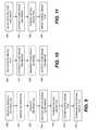
- FIG. 9is a flow diagram of a method according to an embodiment of the present invention.
- FIG. 10is a flow diagram of a method according to an embodiment of the present invention.
- FIG. 11is a flow diagram of a method according to an embodiment of the present invention.
- a digital image file 10includes an information portion 6 and an image portion 7 .
- the image portion 7includes a first digital image 18 .
- the information portion 6includes a second digital image 8 of a digital code that encodes information associated with or derived from the first digital image 18 . When rendered visible the second digital image 8 is a machine-readable optical code 1 .
- a digital filestores information with binary codes in a storage medium, for example a solid-state memory or rotating magnetic or optical disk.
- the binary codescan represent an image expressed as 8-bit values (i.e. bytes having values of 0-255) or, for black and white images, as 1-bit values separated by arbitrarily selected delimiters.
- FIG. 1Athe binary codes in the digital image file 10 corresponding to the information portion 6 having the second digital image 8 of the machine-readable optical code 1 and the image portion 7 including the first digital image 18 are illustrated as bytes associated in groups of three, each group of three bytes specifying a pixel (e.g.
- FIG. 1Brepresents the same first and second digital image 18 , 8 values as descriptive pixels.
- FIG. 1Crepresents the same first and second digital image 18 , 8 values as visibly rendered images.
- FIG. 1A , 1 B, and 1 Care different representations of the same information.
- FIG. 1Cillustrates the visibly rendered forms of the first and second digital images 8 , 18 .
- the second digital image 8 and the machine-readable optical code 1are distinguished herein to distinguish between the digital form of the second digital image 8 and the visibly rendered form of the second digital image 8 as the machine-readable optical code 1 .
- the information portion 6 of the digital image file 10stores the machine-readable optical code 1 as a second digital image 8 of a digital code encoding first digital image 18 information.
- the informationis encoded in the machine-readable optical code 1 .
- the informationis not stored as a text string (e.g. using ASCII or Unicode character representations), as is commonly found in the prior art.
- the digital codeis a digital structure that encodes information.
- the digital codeis stored as the second digital image 8 within a digital storage medium, such as a memory, that is accessed by a digital computer.
- a digital storage mediumsuch as a memory
- the second digital image 8 of the digital codeis rendered visible, for example by printing or displaying the digital code on a substrate or displaying the digital code on a display
- the second digital image 8 of the digital codeis made visible in the form of the machine-readable optical code 1 .
- To render a digital image visibleis to transform the digital image pixels to a form suitable for output on an output device and to output the rendered digital information on the output device so that it is visible, for example it is viewed by an observer as a print on a substrate or as an image on a display device (e.g. a flat-screen LCD display).
- Software and processors for reading digital image files from a storage device and rendering images on output devices such as printers or displaysare well known in the art, as are the output devices.
- the machine-readable optical code 1encodes information.
- the machine-readable optical code 1encodes information associated with or derived from the first digital image 18 , for example image metadata.
- image metadatacan include image attributes, image pixel statistics, image object information, a universal resource indicator (URI), or semantic image information.
- the informationis encrypted so that when the machine-readable optical code 1 is decoded, the resulting decoded information is encrypted.
- the machine-readable optical code 1is a one-dimensional code, a two-dimensional code, a matrix code, a barcode, or a QR code.
- multiple second digital images 8 of machine-readable optical codes 1are included in the information portion 6 .
- the information encoded in such machine-readable optical codes 1can reference other information relevant to the first digital image 18 , such as related audio or video files, or additional metadata information.
- the information portion 6 of the digital image file 10includes a plurality of second digital images 8 of corresponding digital codes, wherein each digital code encodes information associated with or derived from the first digital image 18 and when the corresponding second digital images 8 are rendered visible become machine-readable optical codes 1 .
- the digital image file 10 of the present inventionis made and stored using suitable systems for such processing and storing operations as are described further below with respect to FIGS. 5-8 .
- information and the first digital image 18is received by using a processor 110 , 34 to receive the first digital image 18 and information, for example by reading from a storage device such as a memory or through a computer network communication.
- the informationis received by analyzing the received first digital image 18 , for example by using the processor 110 , 34 to perform image operations upon the received first digital image 18 or by receiving the information from another source connected to a computer network with the processor 110 , 34 .
- the received first digital image 18is received from a digital photograph of a scene or receiving an image file from another source.
- step 201information is derived from the received image.
- the processor 110 , 34is used to analyze the first digital image 18 to produce information derived from the first digital image 18 .
- the digital codeis produced using the derived information.
- processors and image processing algorithms for extracting image information from imagesare known in the prior art, as are software programs that execute on processors to produce digital codes that, when rendered visible, form machine-readable optical codes 1 .
- the encoded informationis encrypted (step 202 ).
- the informationis encoded with the processor ( 110 or 34 in FIG. 5 or 6 ) as a digital code and rendered as the second digital image 8 of the digital code, that when rendered visible is the machine-readable optical code 1 in step 205 .
- the processor 110 , 34can encode the information as a one-dimensional code, a two-dimensional code, a matrix code, a barcode, or a QR code.
- the two digital images(first digital image 18 and second digital image 8 ) are formatted in the digital image file 10 in step 210 with the information portion 6 including the second digital image 8 of the machine-readable optical code 1 and with the image portion 7 including the first digital image 18 . Formatting and structuring digital image files is well known in the computer science art, for example by writing the information in the desired structure in a memory 40 .
- the formatted digital image file 10is then stored in step 215 in a storage medium, for example in a solid-state memory, a magnetic disk memory, or an optical disk drive 44 .
- a storage mediumfor example in a solid-state memory, a magnetic disk memory, or an optical disk drive 44 .
- Such storage operationsare well-known in the computer science and computer hardware arts.
- the digital image file 10can be communicated (step 220 ) or transported to any desired location or for a desired purpose.
- the processor 110 , 34is used to read the stored digital image file 10 and extract the encoded information in the second digital image 8 or the first digital image 18 from the digital image file 10 .
- the processor 110 , 34forms a plurality of second digital images 8 of a corresponding plurality of digital codes that each encode information associated with or derived from the first digital image 18 and that when rendered visible are machine-readable optical codes 1 .
- the processor 110 , 34stores the second digital images 8 in the information portion 6 of the digital image file 10 .
- the first digital image 18 and second digital image 8are rendered visible and output on to a medium that enables a viewer, user, or image input device to directly perceive the first digital image 18 or to directly perceive the second digital image 8 as the machine-readable optical code 1 .
- the present inventionincludes a method of forming a visual output of the digital image file 10 , including using the processor 110 , 34 to read (step 250 ) the digital image file 10 from a storage medium e.g. hard drive 42 , the digital image file 10 having the image portion 7 including the first digital image 18 and the information portion 6 including the second digital image 8 of a digital code that encodes information associated with or derived from the first digital image 18 .
- the second digital image 8 of the digital code and the first digital image 18are extracted (step 255 ) from a storage medium, for example by reading the corresponding portions of the digital image file 10 from a memory 40 with the processor 110 , 34 .
- the first and second digital images 18 , 8are rendered (step 258 ) for visual output on a desired visual output device.
- the visual output devicean output system 28 or a local display 66 ) is used to produce (step 260 ) a visual output of the first digital image 18 in spatial association with the second digital image 8 , from the rendered first and second digital images 18 , 8 , the rendered and visually output second digital image 8 being the machine-readable optical code 1 .
- in spatial associationmeans that the first and second digital images 18 , 8 are formed on a common substrate adjacent to each other or are closer to each other than to other digital images on the same substrate.
- the encoded informationis encrypted and a method of the present invention includes decrypting the encoded information.
- the machine-readable optical codeis output as a one-dimensional code, a two-dimensional code, a matrix code, a barcode, or a QR code.
- the digital image of the machine-readable code 1 and the first digital image 18are output to the same substrate.
- both the machine-readable optical code 1 and the first digital image 18are printed onto a common substrate 16 .
- the machine-readable code 1 and the first digital image 18are printed adjacent to each other in spatial association (for example as shown in FIG. 4 ) or, where multiple images or codes are printed on the common substrate 16 , the machine-readable optical code 1 is printed closer to the first digital image 18 on the substrate 16 than to any other image printed on the substrate 16 .
- the output deviceis a printer (e.g.
- the substrate 16is a printable substrate, for example paper or photographic paper.
- the output deviceis the local display 66 and the substrate 16 is a display substrate, for example a cathode ray tube, a liquid crystal display substrate, a plasma display substrate, an LED display substrate, an OLED display substrate, or an electrophoretic display substrate.
- human-readable information indicating an association between the machine-readable optical code 1 and the first digital image 18 or describing the function or contents of the machine-readable optical code 1is output onto the substrate 16 . This can inform a human viewer of the first digital image 18 or machine-readable optical code 1 of the information.
- the human-readable informationis rendered as text.
- the human-readable informationcan be the information, or a portion of the information, encoded in the machine-readable optical code 1 .
- imagesare rendered when printed.
- renderingis meant that an image is converted from one format to another to ensure that the rendered image is suitable for output with a particular visual output device such as a printer or display.
- Most output devicesrequire that data be converted from, for example, a storage format to a printing format.
- textis typically stored as ASCII or Unicode bytes in a stored file, but when printed or displayed, the 8- or 16-bit text values are converted to images of the characters referenced by the ASCII or Unicode values that is printed or displayed.
- imagesare stored in memory in compressed JPEG format. The compressed JPEG image must be decompressed and rendered for a visual output device such as a printer or display.
- Such compression, decompression, formatting, and renderingare known in the art.
- the first digital image 18 or the second digital image 8 of the digital codeis rendered for output.
- Either the first digital image 18 or the second digital image 8can be compressed when stored in the digital image file 10 and is decompressed (for example by processor 110 or 34 ) for outputting.
- the machine-readable optical code 1is typically monochrome and relies on large black or white blocks, an image of the machine-readable optical code 1 (such as second digital image 8 ) is readily compressible.
- Rendering and compression and decompression of the second digital image 8 (and first digital image 18 )is included in the various methods of the present invention, as is storing the second digital image 8 of the digital code and first digital image 18 in a compressed format in the digital image file 10 .
- the information encoded in the digital codeis updated, overwritten, or marked with a version number to indicate various features, changes, or history associated with the first digital image 18 .
- a scanneris used to scan the machine-readable optical code 1 to produce an image of the machine-readable optical code and a processor is used to decode encoded information in the image.
- the decoded informationcan be a URI and the processor used to display information associated with the URI, for example in a web page.
- a scanner or digital camerahaving an image sensor 39 , 89 , in a method of making the digital image file 10 from the visible first digital image 18 and from the visible second digital image 8 of the machine-readable optical code 1 , wherein the machine-readable optical code 1 encodes information associated with or derived from the first digital image 18 , the image sensor 39 , 89 (step 280 ) the visible first digital image 18 and the visible second digital image 8 of the machine-readable optical code 1 .
- the machine-readable optical code 1 outputis visibly formed on the substrate 16 and the first digital image 8 is visibly formed on the same substrate 16 or a different substrate 16 .
- Substrates 16can be printable substrates (e.g. paper) or a display substrate (e.g. a flat-screen display).
- the image sensor 39 , 89can be an area sensor (for example as used in a digital camera) or a linear sensor (as used in a linear scanner).
- the second digital image 8 of the machine-readable optical code 1 and the first digital image 18are extracted (step 285 ) from the scanned image and structured appropriately (such as in a memory 40 ) to form the digital image file 10 (step 290 , similar to step 210 ), for example using the processor 34 , 110 ).
- the digital image file 10is stored (step 295 , similar to step 215 ) with an information portion 6 including a second digital image 8 of the machine-readable optical code 1 that encodes information and with an image portion 7 including the image 18 in a storage medium (such as disk drive 44 ).
- the scanned second digital image 8 of the machine-readable optical code 1is processed using image processing algorithms executing on the processor 34 , 110 , to reduce the data storage needed to store the second digital image 8 of the machine-readable optical code 1 in the information portion 6 .
- the machine-readable optical codeis a one-dimensional code, a two-dimensional code, a matrix code, a barcode, or a QR code.
- the machine-readable optical code 1can encode encrypted information.
- the present inventionprovides an advantage in efficiency and robustness in managing image metadata in association with an image, particularly for devices with limited processing or communications ability.
- images or image metadatatend to be provided as either digital information or printed data.
- Printing a digital imageconverts it to hard copy and scanning the printed image converts it back to a digital image.
- An equivalent process as suggested by the prior art for converting metadatarequires printing the metadata, for example as text, to convert it to hard copy, and then scanning the printed text with a scanner, employing optical recognition software to convert the scanned printed text to a form suitable for digital storage as metadata with a digital image.
- Optical recognition softwareis expensive, slow, requires significant computing power, and is error prone.
- the metadata informationis converted to hard copy by printing it in an encoded form as a machine-readable optical code.
- Viewers of the image and associated machine-readable optical codecan employ commercially available smart phones including digital cameras and decoding software to read the encoded information.
- decoding softwareto read the encoded information.
- Such toolsare widely available.
- the substrate on which they are outputis scanned.
- Existing tools for extracting images and images of codesare readily available. The extracted images are then structured as desired and stored as a digital image file 10 .
- Metadatacan be stored in a digital image file 10 in a conventional text form and then to encode the metadata as the machine-readable optical code 1 for printing.
- the machine-readable optical code 1is scanned, the metadata is extracted using optical character recognition and stored in textual form to complete the process.
- this processrequires that tools for encoding and decoding the machine-readable optical code 1 be present in the printers and scanners employed to print or scan the machine-readable optical code 1 .
- tools for encoding and decoding the machine-readable optical code 1are readily available in mobile communication devices such as smart phones, they are not present in typical printers and most scanners.
- the encoded informationis stored in the information portion 6 as the second digital image 8 of the digital code that, when rendered visibly produces the machine-readable optical code 1 .
- the machine-readable optical code 1can be printed using the same hardware and software tools as the first digital image 18 without requiring additional tools.
- image extraction toolse.g. locating the images and cropping them
- No character-recognition software, digital code formation tools, or other analysis toolsare needed.
- the extracted digital images ( 188 )are structured and stored as described above.
- the present inventiontherefore, provides a simple and robust way to associate image metadata (or other information) with an image in both a digital file form and in a hardcopy printed form, or on a display.
- image metadata associated with an imageis converted from digital form to printed form and back to digital form in a robust, low-cost, and efficient manner.
- the machine-readable optical code 1is a one-dimensional barcode, a two-dimensional matrix barcode, or a QR code.
- the imageis a color image or a black-and-white image or other image known in the art.
- the imageis an image of a tree and the machine-readable optical code is a QR code.
- the present inventionis not limited to any particular embodiment of the machine-readable optical code 1 or image or class of images.
- the substrate 16is a printable substrate, for example paper, photographic paper, cloth or any surface capable of receiving marks from an image marking engine.
- the substrate 16is a display substrate controlled by a display device.
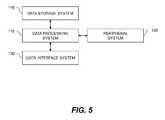
- FIG. 5is a high-level diagram showing the components of a system useful for reading, using, and writing digital image files 10 according to various embodiments of the present invention.
- the systemincludes a data processing system 110 , a peripheral system 120 , a user interface system 130 , and a data storage system 140 .
- the peripheral system 120 , the user interface system 130 and the data storage system 140are communicatively connected to the data processing system 110 .
- the data processing system 110includes one or more data processing devices that implement the processes of the various embodiments of the present invention, including the example processes described herein.
- the phrases “data processing device” or “data processor”are intended to include any data processing device, such as a central processing unit (“CPU”), a desktop computer, a laptop computer, a mainframe computer, a personal digital assistant, a BlackberryTM, a digital camera, a digital picture frame, cellular phone, a smart phone or any other device for processing data, managing data, communicating data, or handling data, whether implemented with electrical, magnetic, optical, biological components, or otherwise.
- CPUcentral processing unit
- BlackberryTMa digital camera
- digital picture framecellular phone
- smart phoneany other device for processing data, managing data, communicating data, or handling data, whether implemented with electrical, magnetic, optical, biological components, or otherwise.
- the data storage system 140includes one or more processor-accessible memories configured to store information, including the information needed to execute the processes of the various embodiments of the present invention, including the example processes described herein.
- the data storage system 140can be a distributed processor-accessible memory system including multiple processor-accessible memories communicatively connected to the data processing system 110 via a plurality of computers or devices.
- the data storage system 140need not be a distributed processor-accessible memory system and, consequently, can include one or more processor-accessible memories located within a single data processor or device.
- processor-accessible memoryis intended to include any processor-accessible data storage device, whether volatile or nonvolatile, electronic, magnetic, optical, or otherwise, including but not limited to, registers, caches, floppy disks, hard disks, Compact Discs, DVDs, flash memories, ROMs, and RAMs.
- the phrase “communicatively connected”is intended to include any type of connection, whether wired or wireless, between devices, data processors, or programs in which data is communicated.
- the phrase “communicatively connected”is intended to include a connection between devices or programs within a single data processor, a connection between devices or programs located in different data processors, and a connection between devices not located in data processors at all.
- the data storage system 140is shown separately from the data processing system 110 , one skilled in the art will appreciate that the data storage system 140 can be stored completely or partially within the data processing system 110 .
- the peripheral system 120 and the user interface system 130are shown separately from the data processing system 110 , one skilled in the art will appreciate that one or both of such systems can be stored completely or partially within the data processing system 110 .
- the peripheral system 120can include one or more devices configured to provide digital content records to the data processing system 110 .
- the peripheral system 120can include digital still cameras, digital video cameras, cellular phones, smart phones, or other data processors.
- the data processing system 110upon receipt of digital content records from a device in the peripheral system 120 , can store such digital content records in the data storage system 140 .
- the user interface system 130can include a mouse, a keyboard, another computer, or any device or combination of devices from which data is input to the data processing system 110 .
- the peripheral system 120is shown separately from the user interface system 130 , the peripheral system 120 can be included as part of the user interface system 130 .
- the user interface system 130also can include a display device, a processor-accessible memory, or any device or combination of devices to which data is output by the data processing system 110 .
- a display devicee.g., a liquid crystal display
- a processor-accessible memorye.g., a liquid crystal display
- any device or combination of devices to which data is output by the data processing system 110e.g., a liquid crystal display
- the user interface system 130includes a processor-accessible memory, such memory can be part of the data storage system 140 even though the user interface system 130 and the data storage system 140 are shown separately in FIG. 5 .
- a computer system for efficiently reading, using, and writing digital image files 10includes an electronic computer system 20 , for example a computer server, connected to a remote electronic computer system 35 , for example a remote client computer, through a computer network, the electronic computer system 20 including memory 40 for storing one or more digital image files 10 communicated through the computer network to the remote electronic computer system 35 , the remote electronic computer system 35 having the display 66 for displaying the digital image files 10 in a graphic user interface.
- the electronic computer system 20includes a source of content data files 24 , a user input system 26 and an output system 28 connected to the processor 34 .
- the source of content data files 24 , user-input system 26 or output system 28 and processor 34are positioned within a housing 22 as illustrated. In other embodiments, circuits and systems of the source of content data files 24 , user input system 26 or output system 28 are positioned in whole or in part outside of housing 22 .
- the source of content data files 24can include any form of electronic or other circuit or system that can supply digital data to processor 34 from which processor 34 can derive images for use in forming a digital image file.
- the content data filescan include, for example and without limitation, still images, image sequences, video graphics, and computer-generated images.
- Source of content data files 24can optionally capture images to create content data for use in content data files by use of capture devices located at, or connected to, electronic computer system 20 or can obtain content data files that have been prepared by or using other devices such as the remote electronic computer system 35 .
- source of content data files 24includes sensors 38 , the memory 40 and a communication system 54 .
- Sensors 38are optional and can include light sensors, biometric sensors and other sensors known in the art that can be used to detect conditions in the environment of electronic computer system 20 and to convert this information into a form used by processor 34 of electronic computer system 20 .
- Sensors 38can also include one or more image sensors 39 that are adapted to capture still or video images.
- Sensors 38can also include biometric or other sensors for measuring involuntary physical and mental reactions such sensors including, but not limited to, voice inflection, body movement, eye movement, pupil dilation, body temperature, and p4000 wave sensors.
- Memory 40can include conventional memory devices including solid-state, magnetic, optical or other data-storage devices. Memory 40 can be fixed within electronic computer system 20 or it can be removable. In the embodiment of FIG. 6 , electronic computer system 20 is shown having a hard drive 42 , a disk drive 44 for a removable disk such as an optical, magnetic or other disk memory (not shown) and a memory card slot 46 that holds a removable memory 48 such as a removable memory card and has a removable memory interface 50 for communicating with removable memory 48 . Data including, but not limited to, control programs, digital images and metadata can also be stored in a remote memory system 52 such as the remote electronic computer system 35 , a personal computer, computer network or other digital system. Remote memory system 52 can also include solid-state, magnetic, optical or other data-storage devices.
- electronic computer system 20has the communication system 54 that in this embodiment is used to communicate with remote electronic computer systems 35 for example including an optional remote memory system 52 , an optional remote display 56 , or optional remote input 58 (also referred to herein as “remote input 58 ”).
- the optional remote memory system 52 , optional remote display 56 , and optional remote input 58can all be part of the remote electronic computer system 35 having the remote input 58 with remote input controls, and that can communicate with communication system 54 wirelessly as illustrated or can communicate in a wired fashion.
- a local input stationincluding either or both of the local display 66 and local input controls 68 (also referred to herein as “local user input 68 ”) are connected to communication system 54 using a wired or wireless connection.
- Communication system 54can include for example, one or more optical, radio frequency or other transducer circuits or other systems that convert image and other data into a form that is conveyed to a remote device such as the remote memory system 52 or the remote display 56 using an optical signal, radio frequency signal or other form of signal.
- Communication system 54can also be used to receive a digital image and other data from a host or server computer or network (not shown), the remote memory system 52 or the remote input 58 .
- Communication system 54provides processor 34 with information and instructions from signals received thereby.
- communication system 54will be adapted to communicate with the remote memory system 52 by way of a communication network such as a conventional telecommunication or data transfer network such as the internet, a cellular, peer-to-peer or other form of mobile telecommunication network, a local communication network such as wired or wireless local area network or any other conventional wired or wireless data transfer system.
- a communication networksuch as a conventional telecommunication or data transfer network such as the internet, a cellular, peer-to-peer or other form of mobile telecommunication network, a local communication network such as wired or wireless local area network or any other conventional wired or wireless data transfer system.
- the electronic computer system 20can provide web access services to remote electronic computer systems 35 that access the electronic computer system 20 through a web browser.
- the remote electronic computer system 35can provide web services to electronic computer system 20 depending on the configurations of the systems.
- User input system 26provides a way for a user 72 of electronic computer system 20 to provide instructions to processor 34 . This permits the user 72 to make a designation of content data files to be used in generating a digital image file and to select an output form for an output product or print. User input system 26 can also be used for a variety of other purposes including, but not limited to, permitting the user 72 to arrange, organize and edit content data files to be incorporated into the image-enhanced output product, to provide information about the user or audience, to provide annotation data such as voice and text data, to identify characters in the content data files, and to perform such other interactions with electronic computer system 20 as are described herein.
- user input system 26can include any form of transducer or other device capable of receiving an input from the user 72 and converting this input into a form used by processor 34 .
- user input system 26can include a touch screen input, a touch pad input, a 4-way switch, a 6-way switch, an 8-way switch, a stylus system, a trackball system, a joystick system, a voice recognition system, a gesture recognition system a keyboard, a remote control or other such systems.
- user input system 26includes an optional remote input 58 including a remote keyboard 58 a , a remote mouse 58 b , and a remote control 58 c and a local user input 68 including a local keyboard 68 a and a local mouse 68 b.
- Remote input 58can take a variety of forms, including, but not limited to, the remote keyboard 58 a , remote mouse 58 b or remote control handheld device 58 c illustrated in FIG. 6 .
- local user input 68can take a variety of forms. In the embodiment of FIG. 6 , local display 66 and local user input 68 are shown directly connected to processor 34 .
- local user input 68can take the form of an editing area 70 such as a home computer, an editing studio, or kiosk that can also be the remote electronic computer system 35 .
- the user 72is seated before a console including local keyboard 68 a and mouse 68 b and a local display 66 which is capable, for example, of displaying multimedia content, for example in a graphic user interface.
- editing area 70can also have sensors 38 including, but not limited to, image sensors 89 , audio sensors 74 and other sensors such as multispectral sensors that can monitor user 72 during a production session or provide other information such as images.
- Output system 28( FIG. 6 ) is used for rendering images, text or other graphical representations in a manner that permits printing image, text, or other graphical representations.
- output system 28can include any conventional structure or system that is known for printing or recording images on output device 32 including, but not limited to, printer 29 .
- Printer 29can record images on a tangible surface 30 using a variety of known technologies including, but not limited to, conventional four-color offset separation printing or other contact printing, silk screening, dry electrophotography such as is used in the NexPress 2100 printer sold by Eastman Kodak Company, Rochester, N.Y., USA, thermal printing technology, drop-on-demand inkjet technology and continuous inkjet technology.
- printer 29will be described as being of a type that generates color images. However, it will be appreciated that this is not needed and that the claimed methods and apparatuses herein can be practiced with the printer 29 that prints monotone images such as black and white, grayscale, or sepia-toned images.
- the electronic computer system 20can be separated from the remote electronic computer system 35 connected to the printer 29 .
- the source of content data files 24 , user input system 26 and output system 28can share components.
- Processor 34operates electronic computer system 20 based upon signals from user input system 26 , sensors 38 , memory 40 and communication system 54 .
- Processor 34can include, but is not limited to, a programmable digital computer, a programmable microprocessor, a programmable logic processor, a series of electronic circuits, a series of electronic circuits reduced to the form of an integrated circuit, or a series of discrete components.
- the remote electronic computer system 35is a mobile communication device 80 , for example a cellular telephone, a smart phone, or a wirelessly connected hand-held computer such as a tablet computer.
- the mobile communication device 80can include the display 66 or the user-input system incorporating the local input 68 keyboard 68 a .
- a local input 68 deviceis a touch screen.
- the mobile communication device 80can communicate with electronic computer system 20 directly, for example through a wireless local area network or a point-to-point wireless connection, or indirectly through a cellular telephony network.
- the electronic computer system 20can be a computer server, for example providing browser-based web pages to a remote electronic computer system 35 , 80 .
- Any of the electronic computer system 20 , remote electronic computer system 35 , or the mobile communication device 80can execute software programs on the internal processor 110 , 34 .
- the software programscan interact with the user 72 through a user interface (e.g. local display 66 and local input 68 ) or with remote computers to accomplish the programmed task.
- the software programscan execute algorithms to analyze data (e.g. digital image files) or to compute useful values.
- a computer software program productcan include one or more non-transitory, tangible, computer readable storage medium, for example; magnetic storage media such as magnetic disk (such as a floppy disk) or magnetic tape; optical storage media such as optical disk, optical tape, or machine readable bar code; solid-state electronic storage devices such as random access memory (RAM), or read-only memory (ROM); or any other physical device or media employed to store a computer program having instructions for controlling one or more computers to practice the method according to the present invention.
- magnetic storage mediasuch as magnetic disk (such as a floppy disk) or magnetic tape
- optical storage mediasuch as optical disk, optical tape, or machine readable bar code
- solid-state electronic storage devicessuch as random access memory (RAM), or read-only memory (ROM); or any other physical device or media employed to store a computer program having instructions for controlling one or more computers to practice the method according to the present invention.
Landscapes
- Engineering & Computer Science (AREA)
- Physics & Mathematics (AREA)
- Theoretical Computer Science (AREA)
- Mathematical Physics (AREA)
- Multimedia (AREA)
- Data Mining & Analysis (AREA)
- Databases & Information Systems (AREA)
- General Engineering & Computer Science (AREA)
- General Physics & Mathematics (AREA)
- Editing Of Facsimile Originals (AREA)
- Processing Or Creating Images (AREA)
Abstract
Description
- 1 machine-readable optical code
- 2 two-dimensional code, QR code, matrix bar code
- 3 dark elements
- 4 light elements
- 5 digital image file
- 6 metadata information portion
- 7 image information portion
- 8 second digital image
- 10 digital image file
- 16 substrate
- 18 first digital image
- 19 human-readable text
- 20 electronic computer system
- 22 housing
- 24 source of content data files
- 26 user input system
- 28 output system
- 29 printer
- 30 tangible surface
- 32 output device
- 34 processor
- 35 remote electronic computer system
- 38 sensors
- 39 image sensors
- 40 memory
- 42 hard drive
- 44 disk drive
- 46 memory card slot
- 48 removable memory
- 50 memory interface
- 52 remote memory system
- 54 communication system
- 56 remote display
- 58 remote input
- 58aremote keyboard
- 58bremote mouse
- 58cremote control
- 66 local display
- 68 local input
- 68alocal keyboard
- 68blocal mouse
- 70 editing area (home computer, editing studio, or kiosk)
- 72 user
- 74 audio sensors
- 80 mobile communication device
- 89 image sensor
- 110 data processing system
- 120 peripheral system
- 130 user interface system
- 140 data storage system
- 200 obtain image and information step
- 201 optional derive information step
- 202 optional encrypt information step
- 205 encode information as machine-readable optical code step
- 210 format digital image file step
- 215 store digital image file step
- 220 communication digital image file step
- 250 read digital image file step
- 255 extract image of code and image step
- 258 render code image or image step
- 260 extract image of code and image step
- 280 scan optical code and image
- 285 extract image of code and image step
- 290 format digital image file step
- 295 store digital image file
Claims (11)
Priority Applications (1)
| Application Number | Priority Date | Filing Date | Title |
|---|---|---|---|
| US13/094,923US8511575B2 (en) | 2011-04-27 | 2011-04-27 | Digital image file including optical code |
Applications Claiming Priority (1)
| Application Number | Priority Date | Filing Date | Title |
|---|---|---|---|
| US13/094,923US8511575B2 (en) | 2011-04-27 | 2011-04-27 | Digital image file including optical code |
Publications (2)
| Publication Number | Publication Date |
|---|---|
| US20120273579A1 US20120273579A1 (en) | 2012-11-01 |
| US8511575B2true US8511575B2 (en) | 2013-08-20 |
Family
ID=47067148
Family Applications (1)
| Application Number | Title | Priority Date | Filing Date |
|---|---|---|---|
| US13/094,923Active2031-10-20US8511575B2 (en) | 2011-04-27 | 2011-04-27 | Digital image file including optical code |
Country Status (1)
| Country | Link |
|---|---|
| US (1) | US8511575B2 (en) |
Cited By (165)
| Publication number | Priority date | Publication date | Assignee | Title |
|---|---|---|---|---|
| US20120273573A1 (en)* | 2011-04-27 | 2012-11-01 | Ronald Steven Cok | Visibly forming an image and optical code |
| US8939343B2 (en) | 1997-09-23 | 2015-01-27 | Covidien Lp | Surgical stapling apparatus including a drive beam |
| US9289211B2 (en) | 2013-03-13 | 2016-03-22 | Covidien Lp | Surgical stapling apparatus |
| US9445811B2 (en) | 2008-09-23 | 2016-09-20 | Covidien Lp | Knife bar for surgical instrument |
| US9498216B2 (en) | 2011-12-01 | 2016-11-22 | Covidien Lp | Surgical instrument with actuator spring arm |
| US9629628B2 (en) | 2013-03-13 | 2017-04-25 | Covidien Lp | Surgical stapling apparatus |
| US9655617B2 (en) | 2007-08-31 | 2017-05-23 | Covidien Lp | Surgical instrument |
| US9662108B2 (en) | 2013-08-30 | 2017-05-30 | Covidien Lp | Surgical stapling apparatus |
| US9668733B2 (en) | 2014-04-21 | 2017-06-06 | Covidien Lp | Stapling device with features to prevent inadvertent firing of staples |
| US9717498B2 (en) | 2013-03-13 | 2017-08-01 | Covidien Lp | Surgical stapling apparatus |
| US9724093B2 (en) | 2008-09-23 | 2017-08-08 | Covidien Lp | Surgical instrument and loading unit for use therewith |
| US9757126B2 (en) | 2014-03-31 | 2017-09-12 | Covidien Lp | Surgical stapling apparatus with firing lockout mechanism |
| US9814463B2 (en) | 2013-03-13 | 2017-11-14 | Covidien Lp | Surgical stapling apparatus |
| US9820737B2 (en) | 2006-10-06 | 2017-11-21 | Covidien Lp | Surgical instrument including a locking assembly |
| US9848874B2 (en) | 2014-02-14 | 2017-12-26 | Covidien Lp | Small diameter endoscopic stapler |
| US9861366B2 (en) | 2014-05-06 | 2018-01-09 | Covidien Lp | Ejecting assembly for a surgical stapler |
| US9867613B2 (en) | 2013-12-19 | 2018-01-16 | Covidien Lp | Surgical staples and end effectors for deploying the same |
| US9918717B2 (en) | 2015-03-18 | 2018-03-20 | Covidien Lp | Pivot mechanism for surgical device |
| US9987012B2 (en) | 2015-07-21 | 2018-06-05 | Covidien Lp | Small diameter cartridge design for a surgical stapling instrument |
| US10039532B2 (en) | 2015-05-06 | 2018-08-07 | Covidien Lp | Surgical instrument with articulation assembly |
| US10039545B2 (en) | 2015-02-23 | 2018-08-07 | Covidien Lp | Double fire stapling |
| US10045782B2 (en) | 2015-07-30 | 2018-08-14 | Covidien Lp | Surgical stapling loading unit with stroke counter and lockout |
| US10064622B2 (en) | 2015-07-29 | 2018-09-04 | Covidien Lp | Surgical stapling loading unit with stroke counter and lockout |
| USD829902S1 (en) | 2015-02-26 | 2018-10-02 | Covidien Lp | Shipping wedge |
| US10085749B2 (en) | 2015-02-26 | 2018-10-02 | Covidien Lp | Surgical apparatus with conductor strain relief |
| US10111660B2 (en) | 2015-12-03 | 2018-10-30 | Covidien Lp | Surgical stapler flexible distal tip |
| US10117650B2 (en) | 2015-05-05 | 2018-11-06 | Covidien Lp | Adapter assembly and loading units for surgical stapling devices |
| US10172615B2 (en) | 2015-05-27 | 2019-01-08 | Covidien Lp | Multi-fire push rod stapling device |
| US10213204B2 (en) | 2015-10-02 | 2019-02-26 | Covidien Lp | Micro surgical instrument and loading unit for use therewith |
| US10299790B2 (en) | 2017-03-03 | 2019-05-28 | Covidien Lp | Adapter with centering mechanism for articulation joint |
| US10299789B2 (en) | 2015-05-05 | 2019-05-28 | Covidie LP | Adapter assembly for surgical stapling devices |
| US10349937B2 (en) | 2016-02-10 | 2019-07-16 | Covidien Lp | Surgical stapler with articulation locking mechanism |
| US10349941B2 (en) | 2015-05-27 | 2019-07-16 | Covidien Lp | Multi-fire lead screw stapling device |
| US10390826B2 (en) | 2017-05-08 | 2019-08-27 | Covidien Lp | Surgical stapling device with elongated tool assembly and methods of use |
| US10420551B2 (en) | 2017-05-30 | 2019-09-24 | Covidien Lp | Authentication and information system for reusable surgical instruments |
| US10420559B2 (en) | 2016-02-11 | 2019-09-24 | Covidien Lp | Surgical stapler with small diameter endoscopic portion |
| US10463371B2 (en) | 2016-11-29 | 2019-11-05 | Covidien Lp | Reload assembly with spent reload indicator |
| US10463368B2 (en) | 2015-04-10 | 2019-11-05 | Covidien Lp | Endoscopic stapler |
| US10478185B2 (en) | 2017-06-02 | 2019-11-19 | Covidien Lp | Tool assembly with minimal dead space |
| US10492784B2 (en) | 2016-11-08 | 2019-12-03 | Covidien Lp | Surgical tool assembly with compact firing assembly |
| US10512461B2 (en) | 2014-05-15 | 2019-12-24 | Covidien Lp | Surgical fastener applying apparatus |
| US10517589B2 (en) | 2017-05-05 | 2019-12-31 | Covidien Lp | Surgical staples with expandable backspan |
| US10517593B2 (en) | 2013-11-04 | 2019-12-31 | Covidien Lp | Surgical fastener applying apparatus |
| US10548599B2 (en) | 2015-07-20 | 2020-02-04 | Covidien Lp | Endoscopic stapler and staple |
| US10561419B2 (en) | 2016-05-04 | 2020-02-18 | Covidien Lp | Powered end effector assembly with pivotable channel |
| US10595864B2 (en) | 2015-11-24 | 2020-03-24 | Covidien Lp | Adapter assembly for interconnecting electromechanical surgical devices and surgical loading units, and surgical systems thereof |
| US10603035B2 (en) | 2017-05-02 | 2020-03-31 | Covidien Lp | Surgical loading unit including an articulating end effector |
| WO2020068077A1 (en)* | 2018-09-26 | 2020-04-02 | Hewlett-Packard Development Company, L.P. | Detected media printing |
| US10624636B2 (en) | 2017-08-23 | 2020-04-21 | Covidien Lp | Surgical stapling device with floating staple cartridge |
| US10631857B2 (en) | 2016-11-04 | 2020-04-28 | Covidien Lp | Loading unit for surgical instruments with low profile pushers |
| US10660641B2 (en) | 2017-03-16 | 2020-05-26 | Covidien Lp | Adapter with centering mechanism for articulation joint |
| US10660623B2 (en) | 2016-01-15 | 2020-05-26 | Covidien Lp | Centering mechanism for articulation joint |
| US10709901B2 (en) | 2017-01-05 | 2020-07-14 | Covidien Lp | Implantable fasteners, applicators, and methods for brachytherapy |
| US10736631B2 (en) | 2018-08-07 | 2020-08-11 | Covidien Lp | End effector with staple cartridge ejector |
| US10772632B2 (en) | 2015-10-28 | 2020-09-15 | Covidien Lp | Surgical stapling device with triple leg staples |
| US10806452B2 (en) | 2017-08-24 | 2020-10-20 | Covidien Lp | Loading unit for a surgical stapling instrument |
| US10849621B2 (en) | 2017-02-23 | 2020-12-01 | Covidien Lp | Surgical stapler with small diameter endoscopic portion |
| US10849620B2 (en) | 2018-09-14 | 2020-12-01 | Covidien Lp | Connector mechanisms for surgical stapling instruments |
| US10849622B2 (en) | 2018-06-21 | 2020-12-01 | Covidien Lp | Articulated stapling with fire lock |
| US10863987B2 (en) | 2017-11-16 | 2020-12-15 | Covidien Lp | Surgical instrument with imaging device |
| US10912563B2 (en) | 2019-01-02 | 2021-02-09 | Covidien Lp | Stapling device including tool assembly stabilizing member |
| US10925603B2 (en) | 2017-11-14 | 2021-02-23 | Covidien Lp | Reload with articulation stabilization system |
| US10945732B2 (en) | 2018-01-17 | 2021-03-16 | Covidien Lp | Surgical stapler with self-returning assembly |
| US10952731B2 (en) | 2013-11-04 | 2021-03-23 | Covidien Lp | Surgical fastener applying apparatus |
| US10952767B2 (en) | 2017-02-06 | 2021-03-23 | Covidien Lp | Connector clip for securing an introducer to a surgical fastener applying apparatus |
| US10966717B2 (en) | 2016-01-07 | 2021-04-06 | Covidien Lp | Surgical fastener apparatus |
| US11033264B2 (en) | 2013-11-04 | 2021-06-15 | Covidien Lp | Surgical fastener applying apparatus |
| US11065022B2 (en) | 2016-05-17 | 2021-07-20 | Covidien Lp | Cutting member for a surgical instrument |
| US11090051B2 (en) | 2018-10-23 | 2021-08-17 | Covidien Lp | Surgical stapling device with floating staple cartridge |
| US11109862B2 (en) | 2019-12-12 | 2021-09-07 | Covidien Lp | Surgical stapling device with flexible shaft |
| US11123068B2 (en) | 2019-11-08 | 2021-09-21 | Covidien Lp | Surgical staple cartridge |
| US11191537B1 (en) | 2020-05-12 | 2021-12-07 | Covidien Lp | Stapling device with continuously parallel jaws |
| US11191538B1 (en) | 2020-06-08 | 2021-12-07 | Covidien Lp | Surgical stapling device with parallel jaw closure |
| US11197673B2 (en) | 2018-10-30 | 2021-12-14 | Covidien Lp | Surgical stapling instruments and end effector assemblies thereof |
| US11224424B2 (en) | 2019-08-02 | 2022-01-18 | Covidien Lp | Linear stapling device with vertically movable knife |
| US11241228B2 (en) | 2019-04-05 | 2022-02-08 | Covidien Lp | Surgical instrument including an adapter assembly and an articulating surgical loading unit |
| US11246593B2 (en) | 2020-03-06 | 2022-02-15 | Covidien Lp | Staple cartridge |
| US11259808B2 (en) | 2019-03-13 | 2022-03-01 | Covidien Lp | Tool assemblies with a gap locking member |
| US11266402B2 (en) | 2020-07-30 | 2022-03-08 | Covidien Lp | Sensing curved tip for surgical stapling instruments |
| US11278282B2 (en) | 2020-01-31 | 2022-03-22 | Covidien Lp | Stapling device with selective cutting |
| US11284893B2 (en) | 2019-04-02 | 2022-03-29 | Covidien Lp | Stapling device with articulating tool assembly |
| US11284892B2 (en) | 2019-04-02 | 2022-03-29 | Covidien Lp | Loading unit and adapter with modified coupling assembly |
| US11317911B2 (en) | 2020-03-10 | 2022-05-03 | Covidien Lp | Tool assembly with replaceable cartridge assembly |
| US11324500B2 (en) | 2020-06-30 | 2022-05-10 | Covidien Lp | Surgical stapling device |
| US11331098B2 (en) | 2020-04-01 | 2022-05-17 | Covidien Lp | Sled detection device |
| US11344301B2 (en) | 2020-03-02 | 2022-05-31 | Covidien Lp | Surgical stapling device with replaceable reload assembly |
| US11344302B2 (en) | 2020-03-05 | 2022-05-31 | Covidien Lp | Articulation mechanism for surgical stapling device |
| US11344297B2 (en) | 2019-02-28 | 2022-05-31 | Covidien Lp | Surgical stapling device with independently movable jaws |
| US11350915B2 (en) | 2017-02-23 | 2022-06-07 | Covidien Lp | Surgical stapler with small diameter endoscopic portion |
| US11357505B2 (en) | 2020-03-10 | 2022-06-14 | Covidien Lp | Surgical stapling apparatus with firing lockout mechanism |
| US11369371B2 (en) | 2018-03-02 | 2022-06-28 | Covidien Lp | Surgical stapling instrument |
| US11395654B2 (en) | 2020-08-07 | 2022-07-26 | Covidien Lp | Surgical stapling device with articulation braking assembly |
| US11406387B2 (en) | 2020-05-12 | 2022-08-09 | Covidien Lp | Surgical stapling device with replaceable staple cartridge |
| US11406383B2 (en) | 2020-03-17 | 2022-08-09 | Covidien Lp | Fire assisted powered EGIA handle |
| US11406384B2 (en) | 2020-10-05 | 2022-08-09 | Covidien Lp | Stapling device with drive assembly stop member |
| US11406385B2 (en) | 2019-10-11 | 2022-08-09 | Covidien Lp | Stapling device with a gap locking member |
| US11426159B2 (en) | 2020-04-01 | 2022-08-30 | Covidien Lp | Sled detection device |
| US11439392B2 (en) | 2020-08-03 | 2022-09-13 | Covidien Lp | Surgical stapling device and fastener for pathological exam |
| US11446028B2 (en) | 2020-07-09 | 2022-09-20 | Covidien Lp | Tool assembly with pivotable clamping beam |
| US11452524B2 (en) | 2020-01-31 | 2022-09-27 | Covidien Lp | Surgical stapling device with lockout |
| US11497495B2 (en) | 2021-03-31 | 2022-11-15 | Covidien Lp | Continuous stapler strip for use with a surgical stapling device |
| US11504117B2 (en) | 2020-04-02 | 2022-11-22 | Covidien Lp | Hand-held surgical instruments |
| US11510669B2 (en) | 2020-09-29 | 2022-11-29 | Covidien Lp | Hand-held surgical instruments |
| US11510673B1 (en) | 2021-05-25 | 2022-11-29 | Covidien Lp | Powered stapling device with manual retraction |
| US11517305B2 (en) | 2020-07-09 | 2022-12-06 | Covidien Lp | Contoured staple pusher |
| US11517313B2 (en) | 2021-01-27 | 2022-12-06 | Covidien Lp | Surgical stapling device with laminated drive member |
| US11534167B2 (en) | 2020-05-28 | 2022-12-27 | Covidien Lp | Electrotaxis-conducive stapling |
| US11540831B1 (en) | 2021-08-12 | 2023-01-03 | Covidien Lp | Staple cartridge with actuation sled detection |
| US11553914B2 (en) | 2020-12-22 | 2023-01-17 | Covidien Lp | Surgical stapling device with parallel jaw closure |
| US11576674B2 (en) | 2020-10-06 | 2023-02-14 | Covidien Lp | Surgical stapling device with articulation lock assembly |
| US11576675B2 (en) | 2021-06-07 | 2023-02-14 | Covidien Lp | Staple cartridge with knife |
| US11576670B2 (en) | 2021-05-06 | 2023-02-14 | Covidien Lp | Surgical stapling device with optimized drive assembly |
| US11576671B1 (en) | 2021-08-20 | 2023-02-14 | Covidien Lp | Small diameter linear surgical stapling apparatus |
| US11602344B2 (en) | 2021-06-30 | 2023-03-14 | Covidien Lp | Surgical stapling apparatus with firing lockout assembly |
| US11602342B2 (en) | 2020-08-27 | 2023-03-14 | Covidien Lp | Surgical stapling device with laser probe |
| US11617579B2 (en) | 2021-06-29 | 2023-04-04 | Covidien Lp | Ultra low profile surgical stapling instrument for tissue resections |
| US11642126B2 (en) | 2016-11-04 | 2023-05-09 | Covidien Lp | Surgical stapling apparatus with tissue pockets |
| US11653922B2 (en) | 2021-09-29 | 2023-05-23 | Covidien Lp | Surgical stapling device with firing lockout mechanism |
| US11660092B2 (en) | 2020-09-29 | 2023-05-30 | Covidien Lp | Adapter for securing loading units to handle assemblies of surgical stapling instruments |
| US11660094B2 (en) | 2021-09-29 | 2023-05-30 | Covidien Lp | Surgical fastening instrument with two-part surgical fasteners |
| US11666330B2 (en) | 2021-04-05 | 2023-06-06 | Covidien Lp | Surgical stapling device with lockout mechanism |
| US11678878B2 (en) | 2020-09-16 | 2023-06-20 | Covidien Lp | Articulation mechanism for surgical stapling device |
| US11696755B2 (en) | 2021-05-19 | 2023-07-11 | Covidien Lp | Surgical stapling device with reload assembly removal lockout |
| US11701119B2 (en) | 2021-05-26 | 2023-07-18 | Covidien Lp | Powered stapling device with rack release |
| US11707278B2 (en) | 2020-03-06 | 2023-07-25 | Covidien Lp | Surgical stapler tool assembly to minimize bleeding |
| US11707275B2 (en) | 2021-06-29 | 2023-07-25 | Covidien Lp | Asymmetrical surgical stapling device |
| US11707277B2 (en) | 2021-08-20 | 2023-07-25 | Covidien Lp | Articulating surgical stapling apparatus with pivotable knife bar guide assembly |
| US11707274B2 (en) | 2019-12-06 | 2023-07-25 | Covidien Lp | Articulating mechanism for surgical instrument |
| US11717300B2 (en) | 2021-03-11 | 2023-08-08 | Covidien Lp | Surgical stapling apparatus with integrated visualization |
| US11723660B2 (en) | 2017-05-02 | 2023-08-15 | Covidien Lp | Surgical loading unit including an articulating end effector |
| US11737747B2 (en) | 2019-12-17 | 2023-08-29 | Covidien Lp | Hand-held surgical instruments |
| US11737774B2 (en) | 2020-12-04 | 2023-08-29 | Covidien Lp | Surgical instrument with articulation assembly |
| US11744582B2 (en) | 2021-01-05 | 2023-09-05 | Covidien Lp | Surgical stapling device with firing lockout mechanism |
| US11759207B2 (en) | 2021-01-27 | 2023-09-19 | Covidien Lp | Surgical stapling apparatus with adjustable height clamping member |
| US11759206B2 (en) | 2021-01-05 | 2023-09-19 | Covidien Lp | Surgical stapling device with firing lockout mechanism |
| US11771423B2 (en) | 2021-05-25 | 2023-10-03 | Covidien Lp | Powered stapling device with manual retraction |
| US11779334B2 (en) | 2021-08-19 | 2023-10-10 | Covidien Lp | Surgical stapling device including a manual retraction assembly |
| US11812956B2 (en) | 2021-05-18 | 2023-11-14 | Covidien Lp | Dual firing radial stapling device |
| US11819200B2 (en) | 2020-12-15 | 2023-11-21 | Covidien Lp | Surgical instrument with articulation assembly |
| US11844517B2 (en) | 2020-06-25 | 2023-12-19 | Covidien Lp | Linear stapling device with continuously parallel jaws |
| US11849949B2 (en) | 2021-09-30 | 2023-12-26 | Covidien Lp | Surgical stapling device with firing lockout member |
| US11864761B2 (en) | 2021-09-14 | 2024-01-09 | Covidien Lp | Surgical instrument with illumination mechanism |
| US11890014B2 (en) | 2020-02-14 | 2024-02-06 | Covidien Lp | Cartridge holder for surgical staples and having ridges in peripheral walls for gripping tissue |
| US11890007B2 (en) | 2020-11-18 | 2024-02-06 | Covidien Lp | Stapling device with flex cable and tensioning mechanism |
| US11937794B2 (en) | 2020-05-11 | 2024-03-26 | Covidien Lp | Powered handle assembly for surgical devices |
| US11944304B2 (en) | 2017-02-22 | 2024-04-02 | Covidien Lp | Loading unit for surgical instruments with low profile pushers |
| US11974743B2 (en) | 2019-12-02 | 2024-05-07 | Covidien Lp | Linear stapling device with a gap locking member |
| US11974750B2 (en) | 2021-03-26 | 2024-05-07 | Covidien Lp | Surgical staple cartridge |
| US12023027B2 (en) | 2020-07-02 | 2024-07-02 | Covidien Lp | Surgical stapling device with compressible staple cartridge |
| US12023028B2 (en) | 2021-08-20 | 2024-07-02 | Covidien Lp | Articulating surgical stapling apparatus with pivotable knife bar guide assembly |
| US12035909B2 (en) | 2021-10-13 | 2024-07-16 | Covidien Lp | Surgical stapling device with firing lockout mechanism |
| US12089838B2 (en) | 2020-07-21 | 2024-09-17 | Covidien Lp | Shipping cover for staple cartridge |
| US12108953B2 (en) | 2020-03-24 | 2024-10-08 | Covidien Lp | Surgical stapling device with replaceable staple cartridge |
| US12133650B2 (en) | 2015-05-25 | 2024-11-05 | Covidien Lp | Small diameter surgical stapling device |
| US12137905B2 (en) | 2022-05-16 | 2024-11-12 | Covidien Lp | Gas-powered continuous feed surgical fastening device |
| US12156651B2 (en) | 2020-02-03 | 2024-12-03 | Covidien Lp | Surgical stapling device |
| US12161322B2 (en) | 2013-03-13 | 2024-12-10 | Covidien Lp | Surgical stapling apparatus |
| US12193666B2 (en) | 2022-05-27 | 2025-01-14 | Covidien Lp | Replaceable staple cartridge with retractable knife |
| US20250036900A1 (en)* | 2023-07-26 | 2025-01-30 | Hand Held Products, Inc. | Methods, systems, and apparatuses for verifying embedded graphical indicia |
| US12220124B2 (en) | 2020-02-14 | 2025-02-11 | Covidien Lp | Surgical stapling device |
| US12268389B2 (en) | 2021-11-12 | 2025-04-08 | Covidien Lp | Surgical stapling device with firing lockout |
| US12336708B2 (en) | 2020-12-23 | 2025-06-24 | Covidien Lp | Surgical instrument including a decoupling mechanism |
| US12349902B2 (en) | 2020-07-09 | 2025-07-08 | Covidien Lp | Powered handle assembly for surgical devices |
| US12383260B2 (en) | 2019-12-13 | 2025-08-12 | Covidien Lp | Surgical stapler with universal tip reload |
| US12414770B2 (en) | 2021-05-21 | 2025-09-16 | Covidien Lp | Articulation assembly for a surgical device |
Families Citing this family (2)
| Publication number | Priority date | Publication date | Assignee | Title |
|---|---|---|---|---|
| KR101440766B1 (en)* | 2013-08-09 | 2014-09-18 | 디에스글로벌 (주) | Method for virtual image delivery service using printed matter |
| US9723253B2 (en)* | 2015-03-11 | 2017-08-01 | Sony Interactive Entertainment Inc. | Apparatus and method for automatically generating an optically machine readable code for a captured image |
Citations (13)
| Publication number | Priority date | Publication date | Assignee | Title |
|---|---|---|---|---|
| US6199048B1 (en) | 1995-06-20 | 2001-03-06 | Neomedia Technologies, Inc. | System and method for automatic access of a remote computer over a network |
| US6229964B1 (en) | 1998-02-26 | 2001-05-08 | Eastman Kodak Company | Image with sound playback apparatus |
| US20040096123A1 (en) | 2000-03-28 | 2004-05-20 | Shih Willy C. | Method and system for locating and accessing digitally stored images |
| US20070153303A1 (en)* | 2005-12-28 | 2007-07-05 | Yasushi Abe | Image processing device, image processing method, image processing system, and information recording medium |
| US7273175B2 (en) | 2004-09-07 | 2007-09-25 | Canon Kabushiki Kaisha | Method, an apparatus and a storage medium for locating QR codes |
| US20090078772A1 (en) | 2007-09-20 | 2009-03-26 | Microsoft Corporation | Techniques for decoding images of barcodes |
| US7551780B2 (en)* | 2005-08-23 | 2009-06-23 | Ricoh Co., Ltd. | System and method for using individualized mixed document |
| US7835037B2 (en) | 2006-01-17 | 2010-11-16 | Ricoh Company, Ltd. | Image processing apparatus and image processing method |
| US7841531B2 (en) | 2004-10-27 | 2010-11-30 | Denso Corporation | Camera operating system and matrix code decoding device |
| US7848578B2 (en) | 2004-09-13 | 2010-12-07 | Nokia Corporation | Methods, devices and computer program products for capture and display of visually encoded data and an image |
| US20110145068A1 (en)* | 2007-09-17 | 2011-06-16 | King Martin T | Associating rendered advertisements with digital content |
| US8156115B1 (en)* | 2007-07-11 | 2012-04-10 | Ricoh Co. Ltd. | Document-based networking with mixed media reality |
| US20120132704A1 (en)* | 2010-11-29 | 2012-05-31 | Ncr Corporation | Visual access token |
- 2011
- 2011-04-27USUS13/094,923patent/US8511575B2/enactiveActive
Patent Citations (14)
| Publication number | Priority date | Publication date | Assignee | Title |
|---|---|---|---|---|
| US6199048B1 (en) | 1995-06-20 | 2001-03-06 | Neomedia Technologies, Inc. | System and method for automatic access of a remote computer over a network |
| US6229964B1 (en) | 1998-02-26 | 2001-05-08 | Eastman Kodak Company | Image with sound playback apparatus |
| US20040096123A1 (en) | 2000-03-28 | 2004-05-20 | Shih Willy C. | Method and system for locating and accessing digitally stored images |
| US7123782B2 (en) | 2000-03-28 | 2006-10-17 | Eastman Kodak Company | Method and system for locating and accessing digitally stored images |
| US7273175B2 (en) | 2004-09-07 | 2007-09-25 | Canon Kabushiki Kaisha | Method, an apparatus and a storage medium for locating QR codes |
| US7848578B2 (en) | 2004-09-13 | 2010-12-07 | Nokia Corporation | Methods, devices and computer program products for capture and display of visually encoded data and an image |
| US7841531B2 (en) | 2004-10-27 | 2010-11-30 | Denso Corporation | Camera operating system and matrix code decoding device |
| US7551780B2 (en)* | 2005-08-23 | 2009-06-23 | Ricoh Co., Ltd. | System and method for using individualized mixed document |
| US20070153303A1 (en)* | 2005-12-28 | 2007-07-05 | Yasushi Abe | Image processing device, image processing method, image processing system, and information recording medium |
| US7835037B2 (en) | 2006-01-17 | 2010-11-16 | Ricoh Company, Ltd. | Image processing apparatus and image processing method |
| US8156115B1 (en)* | 2007-07-11 | 2012-04-10 | Ricoh Co. Ltd. | Document-based networking with mixed media reality |
| US20110145068A1 (en)* | 2007-09-17 | 2011-06-16 | King Martin T | Associating rendered advertisements with digital content |
| US20090078772A1 (en) | 2007-09-20 | 2009-03-26 | Microsoft Corporation | Techniques for decoding images of barcodes |
| US20120132704A1 (en)* | 2010-11-29 | 2012-05-31 | Ncr Corporation | Visual access token |
Cited By (258)
| Publication number | Priority date | Publication date | Assignee | Title |
|---|---|---|---|---|
| US9027817B2 (en) | 1997-09-23 | 2015-05-12 | Covidien Lp | Surgical stapling apparatus including sensing mechanism |
| US9566067B2 (en) | 1997-09-23 | 2017-02-14 | Covidien Lp | Surgical stapling apparatus including sensing mechanism |
| US8939343B2 (en) | 1997-09-23 | 2015-01-27 | Covidien Lp | Surgical stapling apparatus including a drive beam |
| US10702265B2 (en) | 2006-10-06 | 2020-07-07 | Covidien Lp | Surgical instrument including a locking assembly |
| US9820737B2 (en) | 2006-10-06 | 2017-11-21 | Covidien Lp | Surgical instrument including a locking assembly |
| US10456135B2 (en) | 2007-08-31 | 2019-10-29 | Covidien Lp | Surgical instrument |
| US9655617B2 (en) | 2007-08-31 | 2017-05-23 | Covidien Lp | Surgical instrument |
| US9445811B2 (en) | 2008-09-23 | 2016-09-20 | Covidien Lp | Knife bar for surgical instrument |
| US9724093B2 (en) | 2008-09-23 | 2017-08-08 | Covidien Lp | Surgical instrument and loading unit for use therewith |
| US10251647B2 (en) | 2008-09-23 | 2019-04-09 | Covidien Lp | Knife bar for surgical instrument |
| US20120273573A1 (en)* | 2011-04-27 | 2012-11-01 | Ronald Steven Cok | Visibly forming an image and optical code |
| US8763904B2 (en)* | 2011-04-27 | 2014-07-01 | Intellectual Ventures Fund 83 Llc | Visibly forming an image and optical code |
| US9498216B2 (en) | 2011-12-01 | 2016-11-22 | Covidien Lp | Surgical instrument with actuator spring arm |
| US9814463B2 (en) | 2013-03-13 | 2017-11-14 | Covidien Lp | Surgical stapling apparatus |
| US9289211B2 (en) | 2013-03-13 | 2016-03-22 | Covidien Lp | Surgical stapling apparatus |
| US9717498B2 (en) | 2013-03-13 | 2017-08-01 | Covidien Lp | Surgical stapling apparatus |
| US9668729B2 (en) | 2013-03-13 | 2017-06-06 | Covidien Lp | Surgical stapling apparatus |
| US10959726B2 (en) | 2013-03-13 | 2021-03-30 | Covidien Lp | Surgical stapling apparatus |
| US9668728B2 (en) | 2013-03-13 | 2017-06-06 | Covidien Lp | Surgical stapling apparatus |
| US11395656B2 (en) | 2013-03-13 | 2022-07-26 | Covidien Lp | Surgical stapling apparatus |
| US10182815B2 (en) | 2013-03-13 | 2019-01-22 | Covidien Lp | Surgical stapling apparatus |
| US10702271B2 (en) | 2013-03-13 | 2020-07-07 | Covidien Lp | Surgical stapling apparatus |
| US10499915B2 (en) | 2013-03-13 | 2019-12-10 | Covidien Lp | Surgical stapling apparatus |
| US9888921B2 (en) | 2013-03-13 | 2018-02-13 | Covidien Lp | Surgical stapling apparatus |
| US9629628B2 (en) | 2013-03-13 | 2017-04-25 | Covidien Lp | Surgical stapling apparatus |
| US12161322B2 (en) | 2013-03-13 | 2024-12-10 | Covidien Lp | Surgical stapling apparatus |
| US11376004B2 (en) | 2013-03-13 | 2022-07-05 | Covidien Lp | Surgical stapling apparatus |
| US9566064B2 (en) | 2013-03-13 | 2017-02-14 | Covidien Lp | Surgical stapling apparatus |
| US11717287B2 (en) | 2013-03-13 | 2023-08-08 | Covidien Lp | Surgical stapling apparatus |
| US11284889B2 (en) | 2013-08-30 | 2022-03-29 | Covidien Lp | Surgical stapling apparatus |
| US10610220B2 (en) | 2013-08-30 | 2020-04-07 | Covidien Lp | Surgical stapling apparatus |
| US9662108B2 (en) | 2013-08-30 | 2017-05-30 | Covidien Lp | Surgical stapling apparatus |
| US11033264B2 (en) | 2013-11-04 | 2021-06-15 | Covidien Lp | Surgical fastener applying apparatus |
| US10517593B2 (en) | 2013-11-04 | 2019-12-31 | Covidien Lp | Surgical fastener applying apparatus |
| US10952731B2 (en) | 2013-11-04 | 2021-03-23 | Covidien Lp | Surgical fastener applying apparatus |
| US12029418B2 (en) | 2013-12-19 | 2024-07-09 | Covidien Lp | Surgical staples and end effectors for deploying the same |
| US10603034B2 (en) | 2013-12-19 | 2020-03-31 | Covidien Lp | Surgical staples and end effectors for deploying the same |
| US11446026B2 (en) | 2013-12-19 | 2022-09-20 | Covidien Lp | Surgical staples and end effectors for deploying the same |
| US9867613B2 (en) | 2013-12-19 | 2018-01-16 | Covidien Lp | Surgical staples and end effectors for deploying the same |
| US9848874B2 (en) | 2014-02-14 | 2017-12-26 | Covidien Lp | Small diameter endoscopic stapler |
| US9987004B2 (en) | 2014-02-14 | 2018-06-05 | Covidien Lp | Small diameter endoscopic stapler |
| US10499911B2 (en) | 2014-02-14 | 2019-12-10 | Covidien Lp | Small diameter endoscopic stapler |
| US10675023B2 (en) | 2014-03-31 | 2020-06-09 | Covidien Lp | Surgical stapling apparatus with firing lockout mechanism |
| US11399826B2 (en) | 2014-03-31 | 2022-08-02 | Covidien Lp | Surgical stapling apparatus with firing lockout mechanism |
| US9757126B2 (en) | 2014-03-31 | 2017-09-12 | Covidien Lp | Surgical stapling apparatus with firing lockout mechanism |
| US9668733B2 (en) | 2014-04-21 | 2017-06-06 | Covidien Lp | Stapling device with features to prevent inadvertent firing of staples |
| US10751054B2 (en) | 2014-05-06 | 2020-08-25 | Covidien Lp | Ejecting assembly for a surgical stapler |
| US11426166B2 (en) | 2014-05-06 | 2022-08-30 | Covidien Lp | Ejecting assembly for a surgical stapler |
| US9861366B2 (en) | 2014-05-06 | 2018-01-09 | Covidien Lp | Ejecting assembly for a surgical stapler |
| US11497497B2 (en) | 2014-05-15 | 2022-11-15 | Covidien Lp | Surgical fastener applying apparatus |
| US10512461B2 (en) | 2014-05-15 | 2019-12-24 | Covidien Lp | Surgical fastener applying apparatus |
| US10039545B2 (en) | 2015-02-23 | 2018-08-07 | Covidien Lp | Double fire stapling |
| US10327768B2 (en) | 2015-02-23 | 2019-06-25 | Covidien Lp | Double fire stapling |
| USD829903S1 (en) | 2015-02-26 | 2018-10-02 | Covidien Lp | Shipping wedge |
| US10285698B2 (en) | 2015-02-26 | 2019-05-14 | Covidien Lp | Surgical apparatus |
| US10085749B2 (en) | 2015-02-26 | 2018-10-02 | Covidien Lp | Surgical apparatus with conductor strain relief |
| US10987105B2 (en) | 2015-02-26 | 2021-04-27 | Covidien Lp | Surgical apparatus |
| US10918383B2 (en) | 2015-02-26 | 2021-02-16 | Covidien Lp | Surgical apparatus with conductor strain relief |
| USD829902S1 (en) | 2015-02-26 | 2018-10-02 | Covidien Lp | Shipping wedge |
| US11134948B2 (en) | 2015-02-26 | 2021-10-05 | Covidien Lp | Surgical apparatus |
| US10130367B2 (en) | 2015-02-26 | 2018-11-20 | Covidien Lp | Surgical apparatus |
| US11696756B2 (en) | 2015-02-26 | 2023-07-11 | Covidien Lp | Surgical apparatus with conductor strain relief |
| US9918717B2 (en) | 2015-03-18 | 2018-03-20 | Covidien Lp | Pivot mechanism for surgical device |
| US10463368B2 (en) | 2015-04-10 | 2019-11-05 | Covidien Lp | Endoscopic stapler |
| US11426161B2 (en) | 2015-04-10 | 2022-08-30 | Covidien Lp | Endoscopic stapler |
| US10299789B2 (en) | 2015-05-05 | 2019-05-28 | Covidie LP | Adapter assembly for surgical stapling devices |
| US12035907B2 (en) | 2015-05-05 | 2024-07-16 | Covidien Lp | Adapter assembly and loading units for surgical stapling devices |
| US11147548B2 (en) | 2015-05-05 | 2021-10-19 | Covidien Lp | Adapter assembly and loading units for surgical stapling devices |
| US10117650B2 (en) | 2015-05-05 | 2018-11-06 | Covidien Lp | Adapter assembly and loading units for surgical stapling devices |
| US10039532B2 (en) | 2015-05-06 | 2018-08-07 | Covidien Lp | Surgical instrument with articulation assembly |
| US12133650B2 (en) | 2015-05-25 | 2024-11-05 | Covidien Lp | Small diameter surgical stapling device |
| US11510674B2 (en) | 2015-05-27 | 2022-11-29 | Covidien Lp | Multi-fire lead screw stapling device |
| US10912564B2 (en) | 2015-05-27 | 2021-02-09 | Covidien Lp | Multi-fire push rod stapling device |
| US10349941B2 (en) | 2015-05-27 | 2019-07-16 | Covidien Lp | Multi-fire lead screw stapling device |
| US10172615B2 (en) | 2015-05-27 | 2019-01-08 | Covidien Lp | Multi-fire push rod stapling device |
| US10548599B2 (en) | 2015-07-20 | 2020-02-04 | Covidien Lp | Endoscopic stapler and staple |
| US11490893B2 (en) | 2015-07-20 | 2022-11-08 | Covidien Lp | Endoscopic stapler and staple |
| US9987012B2 (en) | 2015-07-21 | 2018-06-05 | Covidien Lp | Small diameter cartridge design for a surgical stapling instrument |
| US10729440B2 (en) | 2015-07-21 | 2020-08-04 | Covidien Lp | Small diameter cartridge design for a surgical stapling instrument |
| US10064622B2 (en) | 2015-07-29 | 2018-09-04 | Covidien Lp | Surgical stapling loading unit with stroke counter and lockout |
| US11033268B2 (en) | 2015-07-29 | 2021-06-15 | Covidien Lp | Surgical stapling loading unit with stroke counter and lockout |
| US10881405B2 (en) | 2015-07-30 | 2021-01-05 | Covidien Lp | Surgical stapling loading unit with stroke counter and lockout |
| US10045782B2 (en) | 2015-07-30 | 2018-08-14 | Covidien Lp | Surgical stapling loading unit with stroke counter and lockout |
| US10213204B2 (en) | 2015-10-02 | 2019-02-26 | Covidien Lp | Micro surgical instrument and loading unit for use therewith |
| US11058427B2 (en) | 2015-10-02 | 2021-07-13 | Covidien Lp | Micro surgical instrument and loading unit for use therewith |
| US10772632B2 (en) | 2015-10-28 | 2020-09-15 | Covidien Lp | Surgical stapling device with triple leg staples |
| US10595864B2 (en) | 2015-11-24 | 2020-03-24 | Covidien Lp | Adapter assembly for interconnecting electromechanical surgical devices and surgical loading units, and surgical systems thereof |
| US10111660B2 (en) | 2015-12-03 | 2018-10-30 | Covidien Lp | Surgical stapler flexible distal tip |
| US10835242B2 (en) | 2015-12-03 | 2020-11-17 | Covidien Lp | Surgical stapler flexible distal tip |
| US10966717B2 (en) | 2016-01-07 | 2021-04-06 | Covidien Lp | Surgical fastener apparatus |
| US10660623B2 (en) | 2016-01-15 | 2020-05-26 | Covidien Lp | Centering mechanism for articulation joint |
| US11439389B2 (en) | 2016-02-10 | 2022-09-13 | Covidien Lp | Surgical stapler with articulation locking mechanism |
| US10349937B2 (en) | 2016-02-10 | 2019-07-16 | Covidien Lp | Surgical stapler with articulation locking mechanism |
| US10966716B2 (en) | 2016-02-10 | 2021-04-06 | Covidien Lp | Surgical stapler with articulation locking mechanism |
| US10420559B2 (en) | 2016-02-11 | 2019-09-24 | Covidien Lp | Surgical stapler with small diameter endoscopic portion |
| US11457920B2 (en) | 2016-02-11 | 2022-10-04 | Covidien Lp | Surgical stapler with small diameter endoscopic portion |
| US10561419B2 (en) | 2016-05-04 | 2020-02-18 | Covidien Lp | Powered end effector assembly with pivotable channel |
| US11065022B2 (en) | 2016-05-17 | 2021-07-20 | Covidien Lp | Cutting member for a surgical instrument |
| US10631857B2 (en) | 2016-11-04 | 2020-04-28 | Covidien Lp | Loading unit for surgical instruments with low profile pushers |
| US11317918B2 (en) | 2016-11-04 | 2022-05-03 | Covidien Lp | Loading unit for surgical instruments with low profile pushers |
| US11931036B2 (en) | 2016-11-04 | 2024-03-19 | Covidien Lp | Loading unit for surgical instruments with low profile pushers |
| US11771429B2 (en) | 2016-11-04 | 2023-10-03 | Covidien Lp | Surgical stapling apparatus with tissue pockets |
| US11642126B2 (en) | 2016-11-04 | 2023-05-09 | Covidien Lp | Surgical stapling apparatus with tissue pockets |
| US10492784B2 (en) | 2016-11-08 | 2019-12-03 | Covidien Lp | Surgical tool assembly with compact firing assembly |
| US11534161B2 (en) | 2016-11-08 | 2022-12-27 | Covidien Lp | Surgical tool assembly with compact firing assembly |
| US10463371B2 (en) | 2016-11-29 | 2019-11-05 | Covidien Lp | Reload assembly with spent reload indicator |
| US11324505B2 (en) | 2016-11-29 | 2022-05-10 | Covidien Lp | Reload assembly with spent reload indicator |
| US11559700B2 (en) | 2017-01-05 | 2023-01-24 | Covidien Lp | Implantable fasteners, applicators, and methods for brachytherapy |
| US10709901B2 (en) | 2017-01-05 | 2020-07-14 | Covidien Lp | Implantable fasteners, applicators, and methods for brachytherapy |
| US10952767B2 (en) | 2017-02-06 | 2021-03-23 | Covidien Lp | Connector clip for securing an introducer to a surgical fastener applying apparatus |
| US11944304B2 (en) | 2017-02-22 | 2024-04-02 | Covidien Lp | Loading unit for surgical instruments with low profile pushers |
| US10849621B2 (en) | 2017-02-23 | 2020-12-01 | Covidien Lp | Surgical stapler with small diameter endoscopic portion |
| US11786247B2 (en) | 2017-02-23 | 2023-10-17 | Covidien Lp | Surgical stapler with small diameter endoscopic portion |
| US11350915B2 (en) | 2017-02-23 | 2022-06-07 | Covidien Lp | Surgical stapler with small diameter endoscopic portion |
| US10299790B2 (en) | 2017-03-03 | 2019-05-28 | Covidien Lp | Adapter with centering mechanism for articulation joint |
| US11337697B2 (en) | 2017-03-03 | 2022-05-24 | Covidien Lp | Adapter with centering mechanism for articulation joint |
| US10667813B2 (en) | 2017-03-03 | 2020-06-02 | Covidien Lp | Adapter with centering mechanism for articulation joint |
| US10660641B2 (en) | 2017-03-16 | 2020-05-26 | Covidien Lp | Adapter with centering mechanism for articulation joint |
| US11723660B2 (en) | 2017-05-02 | 2023-08-15 | Covidien Lp | Surgical loading unit including an articulating end effector |
| US10603035B2 (en) | 2017-05-02 | 2020-03-31 | Covidien Lp | Surgical loading unit including an articulating end effector |
| US11324498B2 (en) | 2017-05-05 | 2022-05-10 | Covidien Lp | Surgical staples with expandable backspan |
| US10517589B2 (en) | 2017-05-05 | 2019-12-31 | Covidien Lp | Surgical staples with expandable backspan |
| US10524784B2 (en) | 2017-05-05 | 2020-01-07 | Covidien Lp | Surgical staples with expandable backspan |
| US11992207B2 (en) | 2017-05-05 | 2024-05-28 | Covidien Lp | Surgical staples with expandable backspan |
| US10390826B2 (en) | 2017-05-08 | 2019-08-27 | Covidien Lp | Surgical stapling device with elongated tool assembly and methods of use |
| US11317916B2 (en) | 2017-05-08 | 2022-05-03 | Covidien Lp | Surgical stapling device with elongated tool assembly and methods of use |
| US10420551B2 (en) | 2017-05-30 | 2019-09-24 | Covidien Lp | Authentication and information system for reusable surgical instruments |
| US11185323B2 (en) | 2017-05-30 | 2021-11-30 | Covidien Lp | Authentication and information system for reusable surgical instruments |
| US10478185B2 (en) | 2017-06-02 | 2019-11-19 | Covidien Lp | Tool assembly with minimal dead space |
| US11617581B2 (en) | 2017-06-02 | 2023-04-04 | Covidien Lp | Tool assembly with minimal dead space |
| US10624636B2 (en) | 2017-08-23 | 2020-04-21 | Covidien Lp | Surgical stapling device with floating staple cartridge |
| US10806452B2 (en) | 2017-08-24 | 2020-10-20 | Covidien Lp | Loading unit for a surgical stapling instrument |
| US10925603B2 (en) | 2017-11-14 | 2021-02-23 | Covidien Lp | Reload with articulation stabilization system |
| US10863987B2 (en) | 2017-11-16 | 2020-12-15 | Covidien Lp | Surgical instrument with imaging device |
| US11744586B2 (en) | 2017-11-16 | 2023-09-05 | Covidien Lp | Surgical instrument with imaging device |
| US10945732B2 (en) | 2018-01-17 | 2021-03-16 | Covidien Lp | Surgical stapler with self-returning assembly |
| US11369371B2 (en) | 2018-03-02 | 2022-06-28 | Covidien Lp | Surgical stapling instrument |
| US11864759B2 (en) | 2018-06-21 | 2024-01-09 | Covidien Lp | Articulated stapling with fire lock |
| US10849622B2 (en) | 2018-06-21 | 2020-12-01 | Covidien Lp | Articulated stapling with fire lock |
| US11547406B2 (en) | 2018-08-07 | 2023-01-10 | Covidien Lp | End effector with staple cartridge ejector |
| US10736631B2 (en) | 2018-08-07 | 2020-08-11 | Covidien Lp | End effector with staple cartridge ejector |
| US11504121B2 (en) | 2018-09-14 | 2022-11-22 | Covidien Lp | Connector mechanisms for surgical stapling instruments |
| US10849620B2 (en) | 2018-09-14 | 2020-12-01 | Covidien Lp | Connector mechanisms for surgical stapling instruments |
| WO2020068077A1 (en)* | 2018-09-26 | 2020-04-02 | Hewlett-Packard Development Company, L.P. | Detected media printing |
| US11321034B2 (en) | 2018-09-26 | 2022-05-03 | Hewlett-Packard Development Company, L.P. | Detected media printing with communicatively linked devices |
| US11806014B2 (en) | 2018-10-23 | 2023-11-07 | Covidien Lp | Surgical stapling device with floating staple cartridge |
| US11090051B2 (en) | 2018-10-23 | 2021-08-17 | Covidien Lp | Surgical stapling device with floating staple cartridge |
| US11197673B2 (en) | 2018-10-30 | 2021-12-14 | Covidien Lp | Surgical stapling instruments and end effector assemblies thereof |
| US10912563B2 (en) | 2019-01-02 | 2021-02-09 | Covidien Lp | Stapling device including tool assembly stabilizing member |
| US11344297B2 (en) | 2019-02-28 | 2022-05-31 | Covidien Lp | Surgical stapling device with independently movable jaws |
| US11890011B2 (en) | 2019-03-13 | 2024-02-06 | Covidien Lp | Tool assemblies with a gap locking member |
| US11259808B2 (en) | 2019-03-13 | 2022-03-01 | Covidien Lp | Tool assemblies with a gap locking member |
| US11890009B2 (en) | 2019-04-02 | 2024-02-06 | Covidien Lp | Loading unit and adapter with modified coupling assembly |
| US11284892B2 (en) | 2019-04-02 | 2022-03-29 | Covidien Lp | Loading unit and adapter with modified coupling assembly |
| US11284893B2 (en) | 2019-04-02 | 2022-03-29 | Covidien Lp | Stapling device with articulating tool assembly |
| US11241228B2 (en) | 2019-04-05 | 2022-02-08 | Covidien Lp | Surgical instrument including an adapter assembly and an articulating surgical loading unit |
| US11925348B2 (en) | 2019-04-05 | 2024-03-12 | Covidien Lp | Surgical instrument including an adapter assembly and an articulating surgical loading unit |
| US11224424B2 (en) | 2019-08-02 | 2022-01-18 | Covidien Lp | Linear stapling device with vertically movable knife |
| US11793517B2 (en) | 2019-08-02 | 2023-10-24 | Covidien Lp | Linear stapling device with vertically movable knife |
| US11406385B2 (en) | 2019-10-11 | 2022-08-09 | Covidien Lp | Stapling device with a gap locking member |
| US11123068B2 (en) | 2019-11-08 | 2021-09-21 | Covidien Lp | Surgical staple cartridge |
| US11974743B2 (en) | 2019-12-02 | 2024-05-07 | Covidien Lp | Linear stapling device with a gap locking member |
| US11707274B2 (en) | 2019-12-06 | 2023-07-25 | Covidien Lp | Articulating mechanism for surgical instrument |
| US11109862B2 (en) | 2019-12-12 | 2021-09-07 | Covidien Lp | Surgical stapling device with flexible shaft |
| US11779335B2 (en) | 2019-12-12 | 2023-10-10 | Covidien Lp | Surgical stapling device with flexible shaft |
| US12383260B2 (en) | 2019-12-13 | 2025-08-12 | Covidien Lp | Surgical stapler with universal tip reload |
| US12268387B2 (en) | 2019-12-17 | 2025-04-08 | Covidien Lp | Hand-held surgical instruments |
| US11737747B2 (en) | 2019-12-17 | 2023-08-29 | Covidien Lp | Hand-held surgical instruments |
| US11696758B2 (en) | 2020-01-31 | 2023-07-11 | Covidien Lp | Stapling device with selective cutting |
| US11452524B2 (en) | 2020-01-31 | 2022-09-27 | Covidien Lp | Surgical stapling device with lockout |
| US11278282B2 (en) | 2020-01-31 | 2022-03-22 | Covidien Lp | Stapling device with selective cutting |
| US12156651B2 (en) | 2020-02-03 | 2024-12-03 | Covidien Lp | Surgical stapling device |
| US11890014B2 (en) | 2020-02-14 | 2024-02-06 | Covidien Lp | Cartridge holder for surgical staples and having ridges in peripheral walls for gripping tissue |
| US12220124B2 (en) | 2020-02-14 | 2025-02-11 | Covidien Lp | Surgical stapling device |
| US11944298B2 (en) | 2020-03-02 | 2024-04-02 | Covidien Lp | Surgical stapling device with replaceable reload assembly |
| US11344301B2 (en) | 2020-03-02 | 2022-05-31 | Covidien Lp | Surgical stapling device with replaceable reload assembly |
| US11344302B2 (en) | 2020-03-05 | 2022-05-31 | Covidien Lp | Articulation mechanism for surgical stapling device |
| US11684364B2 (en) | 2020-03-05 | 2023-06-27 | Covidien Lp | Articulation mechanism for surgical stapling device |
| US11246593B2 (en) | 2020-03-06 | 2022-02-15 | Covidien Lp | Staple cartridge |
| US11707278B2 (en) | 2020-03-06 | 2023-07-25 | Covidien Lp | Surgical stapler tool assembly to minimize bleeding |
| US11723656B2 (en) | 2020-03-10 | 2023-08-15 | Covidien Lp | Tool assembly with replaceable cartridge assembly |
| US11357505B2 (en) | 2020-03-10 | 2022-06-14 | Covidien Lp | Surgical stapling apparatus with firing lockout mechanism |
| US11317911B2 (en) | 2020-03-10 | 2022-05-03 | Covidien Lp | Tool assembly with replaceable cartridge assembly |
| US11737753B2 (en) | 2020-03-10 | 2023-08-29 | Covidien Lp | Surgical stapling apparatus with firing lockout mechanism |
| US11406383B2 (en) | 2020-03-17 | 2022-08-09 | Covidien Lp | Fire assisted powered EGIA handle |
| US12108953B2 (en) | 2020-03-24 | 2024-10-08 | Covidien Lp | Surgical stapling device with replaceable staple cartridge |
| US11331098B2 (en) | 2020-04-01 | 2022-05-17 | Covidien Lp | Sled detection device |
| US11701108B2 (en) | 2020-04-01 | 2023-07-18 | Covidien Lp | Sled detection device |
| US11426159B2 (en) | 2020-04-01 | 2022-08-30 | Covidien Lp | Sled detection device |
| US12029420B2 (en) | 2020-04-01 | 2024-07-09 | Covidien Lp | Sled detection device |
| US11504117B2 (en) | 2020-04-02 | 2022-11-22 | Covidien Lp | Hand-held surgical instruments |
| US11937794B2 (en) | 2020-05-11 | 2024-03-26 | Covidien Lp | Powered handle assembly for surgical devices |
| US11406387B2 (en) | 2020-05-12 | 2022-08-09 | Covidien Lp | Surgical stapling device with replaceable staple cartridge |
| US11832815B2 (en) | 2020-05-12 | 2023-12-05 | Covidien Lp | Stapling device with continuously parallel jaws |
| US11191537B1 (en) | 2020-05-12 | 2021-12-07 | Covidien Lp | Stapling device with continuously parallel jaws |
| US11534167B2 (en) | 2020-05-28 | 2022-12-27 | Covidien Lp | Electrotaxis-conducive stapling |
| US11191538B1 (en) | 2020-06-08 | 2021-12-07 | Covidien Lp | Surgical stapling device with parallel jaw closure |
| US11766256B2 (en) | 2020-06-08 | 2023-09-26 | Covidien Lp | Surgical stapling device with parallel jaw closure |
| US11844517B2 (en) | 2020-06-25 | 2023-12-19 | Covidien Lp | Linear stapling device with continuously parallel jaws |
| US11324500B2 (en) | 2020-06-30 | 2022-05-10 | Covidien Lp | Surgical stapling device |
| US12023027B2 (en) | 2020-07-02 | 2024-07-02 | Covidien Lp | Surgical stapling device with compressible staple cartridge |
| US11446028B2 (en) | 2020-07-09 | 2022-09-20 | Covidien Lp | Tool assembly with pivotable clamping beam |
| US11517305B2 (en) | 2020-07-09 | 2022-12-06 | Covidien Lp | Contoured staple pusher |
| US12349902B2 (en) | 2020-07-09 | 2025-07-08 | Covidien Lp | Powered handle assembly for surgical devices |
| US12089838B2 (en) | 2020-07-21 | 2024-09-17 | Covidien Lp | Shipping cover for staple cartridge |
| US11266402B2 (en) | 2020-07-30 | 2022-03-08 | Covidien Lp | Sensing curved tip for surgical stapling instruments |
| US11849942B2 (en) | 2020-07-30 | 2023-12-26 | Covidien Lp | Sensing curved tip for surgical stapling instruments |
| US11439392B2 (en) | 2020-08-03 | 2022-09-13 | Covidien Lp | Surgical stapling device and fastener for pathological exam |
| US11395654B2 (en) | 2020-08-07 | 2022-07-26 | Covidien Lp | Surgical stapling device with articulation braking assembly |
| US11602342B2 (en) | 2020-08-27 | 2023-03-14 | Covidien Lp | Surgical stapling device with laser probe |
| US11678878B2 (en) | 2020-09-16 | 2023-06-20 | Covidien Lp | Articulation mechanism for surgical stapling device |
| US11660092B2 (en) | 2020-09-29 | 2023-05-30 | Covidien Lp | Adapter for securing loading units to handle assemblies of surgical stapling instruments |
| US11510669B2 (en) | 2020-09-29 | 2022-11-29 | Covidien Lp | Hand-held surgical instruments |
| US11406384B2 (en) | 2020-10-05 | 2022-08-09 | Covidien Lp | Stapling device with drive assembly stop member |
| US11576674B2 (en) | 2020-10-06 | 2023-02-14 | Covidien Lp | Surgical stapling device with articulation lock assembly |
| US11890007B2 (en) | 2020-11-18 | 2024-02-06 | Covidien Lp | Stapling device with flex cable and tensioning mechanism |
| US11737774B2 (en) | 2020-12-04 | 2023-08-29 | Covidien Lp | Surgical instrument with articulation assembly |
| US11819200B2 (en) | 2020-12-15 | 2023-11-21 | Covidien Lp | Surgical instrument with articulation assembly |
| US11553914B2 (en) | 2020-12-22 | 2023-01-17 | Covidien Lp | Surgical stapling device with parallel jaw closure |
| US12336708B2 (en) | 2020-12-23 | 2025-06-24 | Covidien Lp | Surgical instrument including a decoupling mechanism |
| US11759206B2 (en) | 2021-01-05 | 2023-09-19 | Covidien Lp | Surgical stapling device with firing lockout mechanism |
| US11744582B2 (en) | 2021-01-05 | 2023-09-05 | Covidien Lp | Surgical stapling device with firing lockout mechanism |
| US11517313B2 (en) | 2021-01-27 | 2022-12-06 | Covidien Lp | Surgical stapling device with laminated drive member |
| US12070211B2 (en) | 2021-01-27 | 2024-08-27 | Covidien Lp | Surgical stapling device with laminated drive member |
| US11759207B2 (en) | 2021-01-27 | 2023-09-19 | Covidien Lp | Surgical stapling apparatus with adjustable height clamping member |
| US11717300B2 (en) | 2021-03-11 | 2023-08-08 | Covidien Lp | Surgical stapling apparatus with integrated visualization |
| US11974750B2 (en) | 2021-03-26 | 2024-05-07 | Covidien Lp | Surgical staple cartridge |
| US11497495B2 (en) | 2021-03-31 | 2022-11-15 | Covidien Lp | Continuous stapler strip for use with a surgical stapling device |
| US11666330B2 (en) | 2021-04-05 | 2023-06-06 | Covidien Lp | Surgical stapling device with lockout mechanism |
| US11576670B2 (en) | 2021-05-06 | 2023-02-14 | Covidien Lp | Surgical stapling device with optimized drive assembly |
| US11812956B2 (en) | 2021-05-18 | 2023-11-14 | Covidien Lp | Dual firing radial stapling device |
| US11696755B2 (en) | 2021-05-19 | 2023-07-11 | Covidien Lp | Surgical stapling device with reload assembly removal lockout |
| US12414770B2 (en) | 2021-05-21 | 2025-09-16 | Covidien Lp | Articulation assembly for a surgical device |
| US11771423B2 (en) | 2021-05-25 | 2023-10-03 | Covidien Lp | Powered stapling device with manual retraction |
| US12383262B2 (en) | 2021-05-25 | 2025-08-12 | Covidien Lp | Powered stapling device with manual retraction |
| US11510673B1 (en) | 2021-05-25 | 2022-11-29 | Covidien Lp | Powered stapling device with manual retraction |
| US11701119B2 (en) | 2021-05-26 | 2023-07-18 | Covidien Lp | Powered stapling device with rack release |
| US12207819B2 (en) | 2021-05-26 | 2025-01-28 | Covidien Lp | Powered stapling device with rack release |
| US11576675B2 (en) | 2021-06-07 | 2023-02-14 | Covidien Lp | Staple cartridge with knife |
| US11707275B2 (en) | 2021-06-29 | 2023-07-25 | Covidien Lp | Asymmetrical surgical stapling device |
| US11617579B2 (en) | 2021-06-29 | 2023-04-04 | Covidien Lp | Ultra low profile surgical stapling instrument for tissue resections |
| US11602344B2 (en) | 2021-06-30 | 2023-03-14 | Covidien Lp | Surgical stapling apparatus with firing lockout assembly |
| US11540831B1 (en) | 2021-08-12 | 2023-01-03 | Covidien Lp | Staple cartridge with actuation sled detection |
| US11779334B2 (en) | 2021-08-19 | 2023-10-10 | Covidien Lp | Surgical stapling device including a manual retraction assembly |
| US12023028B2 (en) | 2021-08-20 | 2024-07-02 | Covidien Lp | Articulating surgical stapling apparatus with pivotable knife bar guide assembly |
| US11707277B2 (en) | 2021-08-20 | 2023-07-25 | Covidien Lp | Articulating surgical stapling apparatus with pivotable knife bar guide assembly |
| US11896220B2 (en) | 2021-08-20 | 2024-02-13 | Covidien Lp | Small diameter linear surgical stapling apparatus |
| US11576671B1 (en) | 2021-08-20 | 2023-02-14 | Covidien Lp | Small diameter linear surgical stapling apparatus |
| US11864761B2 (en) | 2021-09-14 | 2024-01-09 | Covidien Lp | Surgical instrument with illumination mechanism |
| US11660094B2 (en) | 2021-09-29 | 2023-05-30 | Covidien Lp | Surgical fastening instrument with two-part surgical fasteners |
| US11653922B2 (en) | 2021-09-29 | 2023-05-23 | Covidien Lp | Surgical stapling device with firing lockout mechanism |
| US12156655B2 (en) | 2021-09-29 | 2024-12-03 | Covidien Lp | Surgical stapling device with firing lockout mechanism |
| US11849949B2 (en) | 2021-09-30 | 2023-12-26 | Covidien Lp | Surgical stapling device with firing lockout member |
| US12035909B2 (en) | 2021-10-13 | 2024-07-16 | Covidien Lp | Surgical stapling device with firing lockout mechanism |
| US12268389B2 (en) | 2021-11-12 | 2025-04-08 | Covidien Lp | Surgical stapling device with firing lockout |
| US12137905B2 (en) | 2022-05-16 | 2024-11-12 | Covidien Lp | Gas-powered continuous feed surgical fastening device |
| US12193666B2 (en) | 2022-05-27 | 2025-01-14 | Covidien Lp | Replaceable staple cartridge with retractable knife |
| US20250036900A1 (en)* | 2023-07-26 | 2025-01-30 | Hand Held Products, Inc. | Methods, systems, and apparatuses for verifying embedded graphical indicia |
Also Published As
| Publication number | Publication date |
|---|---|
| US20120273579A1 (en) | 2012-11-01 |
Similar Documents
| Publication | Publication Date | Title |
|---|---|---|
| US8511575B2 (en) | Digital image file including optical code | |
| US8995032B2 (en) | Producing an image and optical file from a visible first digital image and from a visible second digital image of a machine-readable optical code which encodes information associated with or derived from the first digital image | |
| US8439275B2 (en) | Multi-resolution optical codes | |
| US8807435B2 (en) | Decoding multi-resolution optical codes | |
| TWI534700B (en) | Method for contents delivery service using printed matter | |
| JP5007229B2 (en) | Method, apparatus, and computer program product for capturing and displaying visually encoded data and images | |
| US20120193409A1 (en) | System, Method, and Devices for Managing Symbology Associated with a Product | |
| US20130073687A1 (en) | System for managing information using machine-readable codes | |
| US20130026223A1 (en) | Selecting images using machine-readable codes | |
| US20160283824A1 (en) | Image processing device, image processing method, program, and recording medium | |
| US20190238954A1 (en) | Systems and methods for delivery of audio and video content | |
| US8646691B2 (en) | Apparatus and method for using machine-readable codes | |
| US8844821B2 (en) | Multi-layer barcode for print on demand document management | |
| US11155102B2 (en) | Image to script converter | |
| US8967482B2 (en) | Image selection method using machine-readable codes | |
| US8596523B2 (en) | Index print with machine-readable codes | |
| US8763904B2 (en) | Visibly forming an image and optical code | |
| US8534542B2 (en) | Making an ordered element list | |
| TWI564816B (en) | Electronic apparatus, an information transmitting method and an information reading method | |
| US12265641B1 (en) | Detecting out-of-band screen captures and recordings | |
| US10216990B2 (en) | Selection of machine-readable link type | |
| US20220407981A1 (en) | Image output device, image output system, and image outputting method | |
| JP2003085476A (en) | Distribution method of e-book data using two-dimensional barcode | |
| TWM610515U (en) | Cloud printing system | |
| CN119883149A (en) | Print ticket setting method, ticket printing method and device |
Legal Events
| Date | Code | Title | Description |
|---|---|---|---|
| AS | Assignment | Owner name:EASTMAN KODAK COMPANY, NEW YORK Free format text:ASSIGNMENT OF ASSIGNORS INTEREST;ASSIGNOR:COK, RONALD STEVEN;REEL/FRAME:026185/0677 Effective date:20110426 | |
| AS | Assignment | Owner name:CITICORP NORTH AMERICA, INC., AS AGENT, NEW YORK Free format text:SECURITY INTEREST;ASSIGNORS:EASTMAN KODAK COMPANY;PAKON, INC.;REEL/FRAME:028201/0420 Effective date:20120215 | |
| AS | Assignment | Owner name:KODAK IMAGING NETWORK, INC., CALIFORNIA Free format text:PATENT RELEASE;ASSIGNORS:CITICORP NORTH AMERICA, INC.;WILMINGTON TRUST, NATIONAL ASSOCIATION;REEL/FRAME:029913/0001 Effective date:20130201 Owner name:KODAK AMERICAS, LTD., NEW YORK Free format text:PATENT RELEASE;ASSIGNORS:CITICORP NORTH AMERICA, INC.;WILMINGTON TRUST, NATIONAL ASSOCIATION;REEL/FRAME:029913/0001 Effective date:20130201 Owner name:QUALEX INC., NORTH CAROLINA Free format text:PATENT RELEASE;ASSIGNORS:CITICORP NORTH AMERICA, INC.;WILMINGTON TRUST, NATIONAL ASSOCIATION;REEL/FRAME:029913/0001 Effective date:20130201 Owner name:EASTMAN KODAK COMPANY, NEW YORK Free format text:PATENT RELEASE;ASSIGNORS:CITICORP NORTH AMERICA, INC.;WILMINGTON TRUST, NATIONAL ASSOCIATION;REEL/FRAME:029913/0001 Effective date:20130201 Owner name:KODAK PORTUGUESA LIMITED, NEW YORK Free format text:PATENT RELEASE;ASSIGNORS:CITICORP NORTH AMERICA, INC.;WILMINGTON TRUST, NATIONAL ASSOCIATION;REEL/FRAME:029913/0001 Effective date:20130201 Owner name:CREO MANUFACTURING AMERICA LLC, WYOMING Free format text:PATENT RELEASE;ASSIGNORS:CITICORP NORTH AMERICA, INC.;WILMINGTON TRUST, NATIONAL ASSOCIATION;REEL/FRAME:029913/0001 Effective date:20130201 Owner name:NPEC INC., NEW YORK Free format text:PATENT RELEASE;ASSIGNORS:CITICORP NORTH AMERICA, INC.;WILMINGTON TRUST, NATIONAL ASSOCIATION;REEL/FRAME:029913/0001 Effective date:20130201 Owner name:KODAK PHILIPPINES, LTD., NEW YORK Free format text:PATENT RELEASE;ASSIGNORS:CITICORP NORTH AMERICA, INC.;WILMINGTON TRUST, NATIONAL ASSOCIATION;REEL/FRAME:029913/0001 Effective date:20130201 Owner name:KODAK REALTY, INC., NEW YORK Free format text:PATENT RELEASE;ASSIGNORS:CITICORP NORTH AMERICA, INC.;WILMINGTON TRUST, NATIONAL ASSOCIATION;REEL/FRAME:029913/0001 Effective date:20130201 Owner name:EASTMAN KODAK INTERNATIONAL CAPITAL COMPANY, INC., Free format text:PATENT RELEASE;ASSIGNORS:CITICORP NORTH AMERICA, INC.;WILMINGTON TRUST, NATIONAL ASSOCIATION;REEL/FRAME:029913/0001 Effective date:20130201 Owner name:FPC INC., CALIFORNIA Free format text:PATENT RELEASE;ASSIGNORS:CITICORP NORTH AMERICA, INC.;WILMINGTON TRUST, NATIONAL ASSOCIATION;REEL/FRAME:029913/0001 Effective date:20130201 Owner name:KODAK (NEAR EAST), INC., NEW YORK Free format text:PATENT RELEASE;ASSIGNORS:CITICORP NORTH AMERICA, INC.;WILMINGTON TRUST, NATIONAL ASSOCIATION;REEL/FRAME:029913/0001 Effective date:20130201 Owner name:KODAK AVIATION LEASING LLC, NEW YORK Free format text:PATENT RELEASE;ASSIGNORS:CITICORP NORTH AMERICA, INC.;WILMINGTON TRUST, NATIONAL ASSOCIATION;REEL/FRAME:029913/0001 Effective date:20130201 Owner name:FAR EAST DEVELOPMENT LTD., NEW YORK Free format text:PATENT RELEASE;ASSIGNORS:CITICORP NORTH AMERICA, INC.;WILMINGTON TRUST, NATIONAL ASSOCIATION;REEL/FRAME:029913/0001 Effective date:20130201 Owner name:LASER-PACIFIC MEDIA CORPORATION, NEW YORK Free format text:PATENT RELEASE;ASSIGNORS:CITICORP NORTH AMERICA, INC.;WILMINGTON TRUST, NATIONAL ASSOCIATION;REEL/FRAME:029913/0001 Effective date:20130201 Owner name:PAKON, INC., INDIANA Free format text:PATENT RELEASE;ASSIGNORS:CITICORP NORTH AMERICA, INC.;WILMINGTON TRUST, NATIONAL ASSOCIATION;REEL/FRAME:029913/0001 Effective date:20130201 | |
| AS | Assignment | Owner name:INTELLECTUAL VENTURES FUND 83 LLC, NEVADA Free format text:ASSIGNMENT OF ASSIGNORS INTEREST;ASSIGNOR:EASTMAN KODAK COMPANY;REEL/FRAME:029962/0508 Effective date:20130201 | |
| STCF | Information on status: patent grant | Free format text:PATENTED CASE | |
| CC | Certificate of correction | ||
| FPAY | Fee payment | Year of fee payment:4 | |
| AS | Assignment | Owner name:MONUMENT PEAK VENTURES, LLC, TEXAS Free format text:ASSIGNMENT OF ASSIGNORS INTEREST;ASSIGNOR:INTELLECTUAL VENTURES FUND 83 LLC;REEL/FRAME:041941/0079 Effective date:20170215 | |
| MAFP | Maintenance fee payment | Free format text:PAYMENT OF MAINTENANCE FEE, 8TH YEAR, LARGE ENTITY (ORIGINAL EVENT CODE: M1552); ENTITY STATUS OF PATENT OWNER: LARGE ENTITY Year of fee payment:8 | |
| AS | Assignment | Owner name:MONUMENT PEAK VENTURES, LLC, TEXAS Free format text:RELEASE BY SECURED PARTY;ASSIGNOR:INTELLECTUAL VENTURES FUND 83 LLC;REEL/FRAME:064599/0304 Effective date:20230728 | |
| MAFP | Maintenance fee payment | Free format text:PAYMENT OF MAINTENANCE FEE, 12TH YEAR, LARGE ENTITY (ORIGINAL EVENT CODE: M1553); ENTITY STATUS OF PATENT OWNER: LARGE ENTITY Year of fee payment:12 |