US8511094B2 - Combustion apparatus using pilot fuel selected for reduced emissions - Google Patents
Combustion apparatus using pilot fuel selected for reduced emissionsDownload PDFInfo
- Publication number
- US8511094B2 US8511094B2US11/454,698US45469806AUS8511094B2US 8511094 B2US8511094 B2US 8511094B2US 45469806 AUS45469806 AUS 45469806AUS 8511094 B2US8511094 B2US 8511094B2
- Authority
- US
- United States
- Prior art keywords
- fuel
- pilot
- primary
- combustion
- combustion zone
- Prior art date
- Legal status (The legal status is an assumption and is not a legal conclusion. Google has not performed a legal analysis and makes no representation as to the accuracy of the status listed.)
- Expired - Fee Related, expires
Links
- 239000000446fuelSubstances0.000titleclaimsabstractdescription123
- 238000002485combustion reactionMethods0.000titleclaimsabstractdescription59
- VNWKTOKETHGBQD-UHFFFAOYSA-NmethaneChemical compoundCVNWKTOKETHGBQD-UHFFFAOYSA-N0.000claimsabstractdescription47
- LCGLNKUTAGEVQW-UHFFFAOYSA-NDimethyl etherChemical compoundCOCLCGLNKUTAGEVQW-UHFFFAOYSA-N0.000claimsabstractdescription40
- 239000003345natural gasSubstances0.000claimsabstractdescription21
- 238000009792diffusion processMethods0.000claimsabstractdescription19
- 239000007789gasSubstances0.000claimsdescription8
- 238000004519manufacturing processMethods0.000claimsdescription5
- 238000000034methodMethods0.000claims12
- UHZZMRAGKVHANO-UHFFFAOYSA-Mchlormequat chlorideChemical compound[Cl-].C[N+](C)(C)CCClUHZZMRAGKVHANO-UHFFFAOYSA-M0.000claims2
- 239000012530fluidSubstances0.000claims2
- 230000003197catalytic effectEffects0.000claims1
- 230000001747exhibiting effectEffects0.000claims1
- 238000002407reformingMethods0.000claims1
- MWUXSHHQAYIFBG-UHFFFAOYSA-Nnitrogen oxideInorganic materialsO=[N]MWUXSHHQAYIFBG-UHFFFAOYSA-N0.000description27
- OKKJLVBELUTLKV-UHFFFAOYSA-NMethanolChemical compoundOCOKKJLVBELUTLKV-UHFFFAOYSA-N0.000description19
- ATUOYWHBWRKTHZ-UHFFFAOYSA-NPropaneChemical compoundCCCATUOYWHBWRKTHZ-UHFFFAOYSA-N0.000description6
- LFQSCWFLJHTTHZ-UHFFFAOYSA-NEthanolChemical compoundCCOLFQSCWFLJHTTHZ-UHFFFAOYSA-N0.000description5
- 239000004215Carbon black (E152)Substances0.000description3
- 229930195733hydrocarbonNatural products0.000description3
- 150000002430hydrocarbonsChemical class0.000description3
- 239000000203mixtureSubstances0.000description3
- 239000001294propaneSubstances0.000description3
- IJGRMHOSHXDMSA-UHFFFAOYSA-NAtomic nitrogenChemical compoundN#NIJGRMHOSHXDMSA-UHFFFAOYSA-N0.000description2
- OKTJSMMVPCPJKN-UHFFFAOYSA-NCarbonChemical compound[C]OKTJSMMVPCPJKN-UHFFFAOYSA-N0.000description2
- NINIDFKCEFEMDL-UHFFFAOYSA-NSulfurChemical compound[S]NINIDFKCEFEMDL-UHFFFAOYSA-N0.000description2
- QVGXLLKOCUKJST-UHFFFAOYSA-Natomic oxygenChemical compound[O]QVGXLLKOCUKJST-UHFFFAOYSA-N0.000description2
- 229910052799carbonInorganic materials0.000description2
- 238000006243chemical reactionMethods0.000description2
- 238000002347injectionMethods0.000description2
- 239000007924injectionSubstances0.000description2
- 239000001301oxygenSubstances0.000description2
- 229910052760oxygenInorganic materials0.000description2
- 229910052717sulfurInorganic materials0.000description2
- 239000011593sulfurSubstances0.000description2
- 239000002028BiomassSubstances0.000description1
- OTMSDBZUPAUEDD-UHFFFAOYSA-NEthaneChemical compoundCCOTMSDBZUPAUEDD-UHFFFAOYSA-N0.000description1
- UFHFLCQGNIYNRP-UHFFFAOYSA-NHydrogenChemical compound[H][H]UFHFLCQGNIYNRP-UHFFFAOYSA-N0.000description1
- 239000001273butaneSubstances0.000description1
- 238000010531catalytic reduction reactionMethods0.000description1
- 239000003245coalSubstances0.000description1
- 239000002283diesel fuelSubstances0.000description1
- 230000007613environmental effectEffects0.000description1
- 239000001257hydrogenSubstances0.000description1
- 229910052739hydrogenInorganic materials0.000description1
- 239000003949liquefied natural gasSubstances0.000description1
- 239000007788liquidSubstances0.000description1
- 239000000463materialSubstances0.000description1
- IJDNQMDRQITEOD-UHFFFAOYSA-Nn-butaneChemical compoundCCCCIJDNQMDRQITEOD-UHFFFAOYSA-N0.000description1
- OFBQJSOFQDEBGM-UHFFFAOYSA-Nn-pentaneNatural productsCCCCCOFBQJSOFQDEBGM-UHFFFAOYSA-N0.000description1
- 229910052757nitrogenInorganic materials0.000description1
- 238000005086pumpingMethods0.000description1
- 238000006722reduction reactionMethods0.000description1
- 239000007858starting materialSubstances0.000description1
- 238000006467substitution reactionMethods0.000description1
- 238000011144upstream manufacturingMethods0.000description1
- XLYOFNOQVPJJNP-UHFFFAOYSA-NwaterSubstancesOXLYOFNOQVPJJNP-UHFFFAOYSA-N0.000description1
Images

Classifications
- F—MECHANICAL ENGINEERING; LIGHTING; HEATING; WEAPONS; BLASTING
- F02—COMBUSTION ENGINES; HOT-GAS OR COMBUSTION-PRODUCT ENGINE PLANTS
- F02C—GAS-TURBINE PLANTS; AIR INTAKES FOR JET-PROPULSION PLANTS; CONTROLLING FUEL SUPPLY IN AIR-BREATHING JET-PROPULSION PLANTS
- F02C7/00—Features, components parts, details or accessories, not provided for in, or of interest apart form groups F02C1/00 - F02C6/00; Air intakes for jet-propulsion plants
- F02C7/26—Starting; Ignition
- F—MECHANICAL ENGINEERING; LIGHTING; HEATING; WEAPONS; BLASTING
- F02—COMBUSTION ENGINES; HOT-GAS OR COMBUSTION-PRODUCT ENGINE PLANTS
- F02C—GAS-TURBINE PLANTS; AIR INTAKES FOR JET-PROPULSION PLANTS; CONTROLLING FUEL SUPPLY IN AIR-BREATHING JET-PROPULSION PLANTS
- F02C3/00—Gas-turbine plants characterised by the use of combustion products as the working fluid
- F02C3/20—Gas-turbine plants characterised by the use of combustion products as the working fluid using a special fuel, oxidant, or dilution fluid to generate the combustion products
- F02C3/22—Gas-turbine plants characterised by the use of combustion products as the working fluid using a special fuel, oxidant, or dilution fluid to generate the combustion products the fuel or oxidant being gaseous at standard temperature and pressure
- F—MECHANICAL ENGINEERING; LIGHTING; HEATING; WEAPONS; BLASTING
- F23—COMBUSTION APPARATUS; COMBUSTION PROCESSES
- F23R—GENERATING COMBUSTION PRODUCTS OF HIGH PRESSURE OR HIGH VELOCITY, e.g. GAS-TURBINE COMBUSTION CHAMBERS
- F23R3/00—Continuous combustion chambers using liquid or gaseous fuel
- F23R3/28—Continuous combustion chambers using liquid or gaseous fuel characterised by the fuel supply
- F23R3/286—Continuous combustion chambers using liquid or gaseous fuel characterised by the fuel supply having fuel-air premixing devices
- F—MECHANICAL ENGINEERING; LIGHTING; HEATING; WEAPONS; BLASTING
- F23—COMBUSTION APPARATUS; COMBUSTION PROCESSES
- F23R—GENERATING COMBUSTION PRODUCTS OF HIGH PRESSURE OR HIGH VELOCITY, e.g. GAS-TURBINE COMBUSTION CHAMBERS
- F23R3/00—Continuous combustion chambers using liquid or gaseous fuel
- F23R3/28—Continuous combustion chambers using liquid or gaseous fuel characterised by the fuel supply
- F23R3/34—Feeding into different combustion zones
- F23R3/343—Pilot flames, i.e. fuel nozzles or injectors using only a very small proportion of the total fuel to insure continuous combustion
- F—MECHANICAL ENGINEERING; LIGHTING; HEATING; WEAPONS; BLASTING
- F23—COMBUSTION APPARATUS; COMBUSTION PROCESSES
- F23R—GENERATING COMBUSTION PRODUCTS OF HIGH PRESSURE OR HIGH VELOCITY, e.g. GAS-TURBINE COMBUSTION CHAMBERS
- F23R3/00—Continuous combustion chambers using liquid or gaseous fuel
- F23R3/28—Continuous combustion chambers using liquid or gaseous fuel characterised by the fuel supply
- F23R3/36—Supply of different fuels
- F—MECHANICAL ENGINEERING; LIGHTING; HEATING; WEAPONS; BLASTING
- F05—INDEXING SCHEMES RELATING TO ENGINES OR PUMPS IN VARIOUS SUBCLASSES OF CLASSES F01-F04
- F05D—INDEXING SCHEME FOR ASPECTS RELATING TO NON-POSITIVE-DISPLACEMENT MACHINES OR ENGINES, GAS-TURBINES OR JET-PROPULSION PLANTS
- F05D2270/00—Control
- F05D2270/01—Purpose of the control system
- F05D2270/08—Purpose of the control system to produce clean exhaust gases
- F05D2270/082—Purpose of the control system to produce clean exhaust gases with as little NOx as possible
- F—MECHANICAL ENGINEERING; LIGHTING; HEATING; WEAPONS; BLASTING
- F23—COMBUSTION APPARATUS; COMBUSTION PROCESSES
- F23C—METHODS OR APPARATUS FOR COMBUSTION USING FLUID FUEL OR SOLID FUEL SUSPENDED IN A CARRIER GAS OR AIR
- F23C2900/00—Special features of, or arrangements for combustion apparatus using fluid fuels or solid fuels suspended in air; Combustion processes therefor
- F23C2900/03002—Combustion apparatus adapted for incorporating a fuel reforming device
Definitions
- This inventionrelates generally to the field of gas turbine engines, and more particularly to dry low NOx combustor designs with an air/fuel premixing stage upstream of a primary combustion zone, and with a diffusion pilot flame to stabilize the lean primary combustion.
- N-NOxnitrogen oxides
- Premixing fuel with air to a mixture leaner than stoichiometric equivalencecan reduce the peak combustion temperature.
- This strategyis called Dry Low NOx combustion (DLN), or sometimes Dry Low Emissions combustion (DLE), because it does not depend on water injection to reduce the combustion temperature.
- DNLDry Low NOx combustion
- DLEDry Low Emissions combustion
- a lean burn that is optimum for energy efficiency and low emissionscan be unstable in some conditions.
- many combustor designsuse a non-premixed pilot flame to stabilize a primary premixed flame, thereby reducing combustion dynamics.
- a pilot flameis normally a diffusion burn, which occurs when fuel is injected into the combustor without premixing it with air.
- the fueldiffuses in the combustor air and burns as it diffuses.
- the pilot flame frontmaintains a mixture in the diffusion where the fuel/air ratio is sufficiently rich to ensure combustion stability under nearly all operating conditions.
- a diffusion flameburns at a higher flame temperature and produces more NOx than does a lean premix burn. Combustion temperature and NOx production both peak at or near stoichiometric equivalence, where the amounts of oxygen and fuel are matched for the reaction.
- a relatively small pilot flamecan produce most of the NOx in the combustor.
- Peak flame temperatureis also determined by the fuel selection. Increasing the carbon to hydrogen ratio of a fuel increases its flame temperature, and hence increases NOx production.
- Natural gasis a commonly used gas turbine fuel. It is a mixture of hydrocarbon gases, principally methane together with varying proportions of ethane, propane, butane, and other gases.
- Dimethyl ether(CH 3 OCH 3 ), or DME, can be produced from natural gas and it is one means of delivering natural gas from remote sources.
- Other meansinclude liquefied natural gas and conversion of natural gas to products like methanol, diesel fuel, and jet fuels.
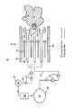
- FIGUREis a schematic illustration of a combustion apparatus using different fuels for a primary combustion zone and a pilot combustion zone.
- Methane (CH 4 ) and natural gasare not oxygenated, and have relatively high ignition temperatures.
- Oxygenated fuelssuch as methanol (CH 3 OH)
- CH 3 OHmethanol
- DMEis an oxygenated fuel with a much lower auto-ignition temperature (about 240° C.) compared to that of natural gas (about 600° C.).
- the present inventorhas innovatively recognized that these characteristics may be exploited in a novel manner to provide a combustion apparatus generating lower oxides of nitrogen than prior art devices.
- FIG. 1schematically illustrates a combustion apparatus 10 including a combustor 12 with a combustor wall 20 enclosing airflow 22 , primary fuel nozzles 24 , a primary combustion zone 25 , a pilot fuel nozzle 28 , and a pilot combustion zone 29 .
- the primary nozzlesare outlets of air/fuel premixers 26 , in which a primary fuel 30 is injected into a portion of the airflow 22 to produce a premix of air and fuel at a desired ratio as known in the art.
- a premixing stage of a combustormay comprise one or more premixers.
- the primary fuel 30may be natural gas or another gaseous or liquid fuel as known in the art.
- the combustion apparatus 10may be part of a gas turbine engine of an electrical power production facility.
- the pilot fuel nozzle 28is supplied with a second type of fuel 40 from a second storage vessel 42 via second fuel system, including a pilot fuel line 46 and pilot fuel controls 48 .
- the second fuel typeis different than the primary fuel 30 and is selected to provide a stable diffusion flame while producing a combustion product with a reduced emission, for example a reduce concentration of NOx, in comparison to a combustion product that would be produced by the burning of the primary fuel 30 with a diffusion pilot stage of the same primary fuel 30 .
- the two fuelsare specialized for their respective roles, increasing overall combustion efficiency and lowering emissions.
- DMEdimethyl ether
- DMEis physically similar to natural gas, but has a lower combustion temperature.
- DMEis a colorless, water-soluble gas with the formula CH 3 OCH 3 . It is a cleaner burning alternative to natural gas.
- DMEis commonly made from natural gas, and can also be made from other hydrocarbon fuel stocks, even coal and biomass. It is called a pilot fuel oxygenate because it contains some oxygen.
- a pilot fuel oxygenatebecause it contains some oxygen.
- DMEburns more stably at a lower temperature. It produces lower NOx, CO, and unconverted hydrocarbon emissions compared to natural gas. Sulfur emission is completely avoided, because DME is sulfur free.
- DMEcan be derived from the same starting materials as methanol, but produces a better quality fuel than methanol.
- DMEhas the vapor pressure of propane, and can be used without additional pumping requirements.
- Other fuels providing a relatively cleaner-burning pilot flame, in particular other oxygenated fuels,may be used in other embodiments.
- Methanolis an oxygenated fuel that may be used for this purpose in one embodiment.
- Ethanolanother alcohol based fuel which is now in wide production in the United States may be used in another embodiment. Ethanol has more carbon bearing material than methanol and produces a higher flame temperature, but one that is still lower than the methane (or propane) found in natural gases.
- Existing DLN combustor designscan be adapted to the present invention by modifying the pilot leg of the existing fuel injection system as needed to provide separate storage and appropriate flow controls for the selected pilot fuel.
- storing and managing two fuelsadds complexity in the fuel system, it may reduce the overall complexity of a combustion system by avoiding the need for selective catalytic reduction (SCR) to meet environmental regulations such as a requirement for less than 5 ppm NOx.
- SCRselective catalytic reduction
- the pilot flowis typically less than 5% of the primary flow. This allows the use of a more costly pilot fuel in order to obtain significantly lower total emissions while maintaining the use of a less costly primary fuel for generating the bulk of the heat energy.
- a bypass line(not shown) may be provided between the primary and secondary fuel systems to temporarily use the primary fuel for the pilot, with an appropriate change in the pilot flow rate being made via the pilot flow controls 48 if needed.
- a reformer 50may be added on site to convert a portion of the primary fuel 30 to the pilot fuel 40 as known in the art.
Landscapes
- Engineering & Computer Science (AREA)
- Chemical & Material Sciences (AREA)
- Combustion & Propulsion (AREA)
- Mechanical Engineering (AREA)
- General Engineering & Computer Science (AREA)
Abstract
Description
Claims (20)
Priority Applications (1)
| Application Number | Priority Date | Filing Date | Title |
|---|---|---|---|
| US11/454,698US8511094B2 (en) | 2006-06-16 | 2006-06-16 | Combustion apparatus using pilot fuel selected for reduced emissions |
Applications Claiming Priority (1)
| Application Number | Priority Date | Filing Date | Title |
|---|---|---|---|
| US11/454,698US8511094B2 (en) | 2006-06-16 | 2006-06-16 | Combustion apparatus using pilot fuel selected for reduced emissions |
Publications (2)
| Publication Number | Publication Date |
|---|---|
| US20070289311A1 US20070289311A1 (en) | 2007-12-20 |
| US8511094B2true US8511094B2 (en) | 2013-08-20 |
Family
ID=38860252
Family Applications (1)
| Application Number | Title | Priority Date | Filing Date |
|---|---|---|---|
| US11/454,698Expired - Fee RelatedUS8511094B2 (en) | 2006-06-16 | 2006-06-16 | Combustion apparatus using pilot fuel selected for reduced emissions |
Country Status (1)
| Country | Link |
|---|---|
| US (1) | US8511094B2 (en) |
Cited By (1)
| Publication number | Priority date | Publication date | Assignee | Title |
|---|---|---|---|---|
| US20190011130A1 (en)* | 2015-08-26 | 2019-01-10 | General Electric Company | Systems and methods for a multi-fuel premixing nozzle with integral liquid injectors/evaporators |
Families Citing this family (7)
| Publication number | Priority date | Publication date | Assignee | Title |
|---|---|---|---|---|
| JP5115372B2 (en)* | 2008-07-11 | 2013-01-09 | トヨタ自動車株式会社 | Operation control device for gas turbine |
| US8661779B2 (en)* | 2008-09-26 | 2014-03-04 | Siemens Energy, Inc. | Flex-fuel injector for gas turbines |
| US9121608B2 (en)* | 2011-12-29 | 2015-09-01 | General Electric Company | Gas turbine engine including secondary combustion chamber integrated with the stator vanes in the turbine/expansion section of the engine and a method of operating the same |
| US10161312B2 (en)* | 2012-11-02 | 2018-12-25 | General Electric Company | System and method for diffusion combustion with fuel-diluent mixing in a stoichiometric exhaust gas recirculation gas turbine system |
| EP3324113A1 (en)* | 2016-11-17 | 2018-05-23 | Saacke GmbH | Method and device for operating a gas combustor |
| DE102023121867A1 (en)* | 2023-08-16 | 2025-02-20 | Forschungszentrum Jülich GmbH | Process for carrying out endothermic production processes and plant for carrying out the process |
| CN119196722A (en)* | 2024-12-03 | 2024-12-27 | 浙江大学 | A multi-mode methanol swirl burner |
Citations (15)
| Publication number | Priority date | Publication date | Assignee | Title |
|---|---|---|---|---|
| US3973390A (en)* | 1974-12-18 | 1976-08-10 | United Technologies Corporation | Combustor employing serially staged pilot combustion, fuel vaporization, and primary combustion zones |
| US4341069A (en) | 1980-04-02 | 1982-07-27 | Mobil Oil Corporation | Method for generating power upon demand |
| US5177114A (en) | 1990-04-11 | 1993-01-05 | Starchem Inc. | Process for recovering natural gas in the form of a normally liquid carbon containing compound |
| US5404711A (en)* | 1993-06-10 | 1995-04-11 | Solar Turbines Incorporated | Dual fuel injector nozzle for use with a gas turbine engine |
| US5740667A (en) | 1994-12-15 | 1998-04-21 | Amoco Corporation | Process for abatement of nitrogen oxides in exhaust from gas turbine power generation |
| US5752489A (en)* | 1997-02-10 | 1998-05-19 | Cummins Engine Company, Inc. | Integrated fuel measurement and control system for gaseous fuels |
| US5946917A (en)* | 1995-06-12 | 1999-09-07 | Siemens Aktiengesellschaft | Catalytic combustion chamber operating on preformed fuel, preferably for a gas turbine |
| US6324827B1 (en) | 1997-07-01 | 2001-12-04 | Bp Corporation North America Inc. | Method of generating power in a dry low NOx combustion system |
| US6422858B1 (en)* | 2000-09-11 | 2002-07-23 | John Zink Company, Llc | Low NOx apparatus and methods for burning liquid and gaseous fuels |
| JP2002285175A (en) | 2001-03-26 | 2002-10-03 | Babcock Hitachi Kk | Combined power generation system with simultaneous dimethyl ether production and method for operating the same |
| JP2004225546A (en) | 2003-01-20 | 2004-08-12 | Mitsubishi Heavy Ind Ltd | Gas turbine plant |
| US6865889B2 (en) | 2002-02-01 | 2005-03-15 | General Electric Company | Method and apparatus to decrease combustor emissions |
| JP2005147136A (en) | 2003-10-23 | 2005-06-09 | Niigata Power Systems Co Ltd | Fuel control device for gas turbine |
| US7041154B2 (en)* | 2003-12-12 | 2006-05-09 | United Technologies Corporation | Acoustic fuel deoxygenation system |
| US7168488B2 (en)* | 2001-08-31 | 2007-01-30 | Statoil Asa | Method and plant or increasing oil recovery by gas injection |
- 2006
- 2006-06-16USUS11/454,698patent/US8511094B2/ennot_activeExpired - Fee Related
Patent Citations (15)
| Publication number | Priority date | Publication date | Assignee | Title |
|---|---|---|---|---|
| US3973390A (en)* | 1974-12-18 | 1976-08-10 | United Technologies Corporation | Combustor employing serially staged pilot combustion, fuel vaporization, and primary combustion zones |
| US4341069A (en) | 1980-04-02 | 1982-07-27 | Mobil Oil Corporation | Method for generating power upon demand |
| US5177114A (en) | 1990-04-11 | 1993-01-05 | Starchem Inc. | Process for recovering natural gas in the form of a normally liquid carbon containing compound |
| US5404711A (en)* | 1993-06-10 | 1995-04-11 | Solar Turbines Incorporated | Dual fuel injector nozzle for use with a gas turbine engine |
| US5740667A (en) | 1994-12-15 | 1998-04-21 | Amoco Corporation | Process for abatement of nitrogen oxides in exhaust from gas turbine power generation |
| US5946917A (en)* | 1995-06-12 | 1999-09-07 | Siemens Aktiengesellschaft | Catalytic combustion chamber operating on preformed fuel, preferably for a gas turbine |
| US5752489A (en)* | 1997-02-10 | 1998-05-19 | Cummins Engine Company, Inc. | Integrated fuel measurement and control system for gaseous fuels |
| US6324827B1 (en) | 1997-07-01 | 2001-12-04 | Bp Corporation North America Inc. | Method of generating power in a dry low NOx combustion system |
| US6422858B1 (en)* | 2000-09-11 | 2002-07-23 | John Zink Company, Llc | Low NOx apparatus and methods for burning liquid and gaseous fuels |
| JP2002285175A (en) | 2001-03-26 | 2002-10-03 | Babcock Hitachi Kk | Combined power generation system with simultaneous dimethyl ether production and method for operating the same |
| US7168488B2 (en)* | 2001-08-31 | 2007-01-30 | Statoil Asa | Method and plant or increasing oil recovery by gas injection |
| US6865889B2 (en) | 2002-02-01 | 2005-03-15 | General Electric Company | Method and apparatus to decrease combustor emissions |
| JP2004225546A (en) | 2003-01-20 | 2004-08-12 | Mitsubishi Heavy Ind Ltd | Gas turbine plant |
| JP2005147136A (en) | 2003-10-23 | 2005-06-09 | Niigata Power Systems Co Ltd | Fuel control device for gas turbine |
| US7041154B2 (en)* | 2003-12-12 | 2006-05-09 | United Technologies Corporation | Acoustic fuel deoxygenation system |
Non-Patent Citations (2)
| Title |
|---|
| David Littlejohn, Waseem Nazeer, Ken O. Smith and Robert K. Cheng, "Low-Swirl DLN Injector for < 5 ppm NOx Gas Turbines", [Found on Web], Date not known, but prior to Dec. 2004, Environmental Energy Technologies Division Lawrence Berkeley National Laboratory, Berkeley, CA and Advanced Combustion Engineering Solar Turbines, San Diego, CA. |
| L.B. Davis and S.H. Black, "Dry Low NOx Combustion Systems for GE Heavy-Duty Gas Turbines", [Found on Web], Oct. 2000, pp. 1-22, GER-3568G, GE Power Systems, Schenectady, NY. |
Cited By (2)
| Publication number | Priority date | Publication date | Assignee | Title |
|---|---|---|---|---|
| US20190011130A1 (en)* | 2015-08-26 | 2019-01-10 | General Electric Company | Systems and methods for a multi-fuel premixing nozzle with integral liquid injectors/evaporators |
| US10731862B2 (en)* | 2015-08-26 | 2020-08-04 | General Electric Company | Systems and methods for a multi-fuel premixing nozzle with integral liquid injectors/evaporators |
Also Published As
| Publication number | Publication date |
|---|---|
| US20070289311A1 (en) | 2007-12-20 |
Similar Documents
| Publication | Publication Date | Title |
|---|---|---|
| US8511094B2 (en) | Combustion apparatus using pilot fuel selected for reduced emissions | |
| US8701383B2 (en) | Late lean injection system configuration | |
| KR100785955B1 (en) | System for vaporization of liquid fuels for combustion and method of use | |
| US8707707B2 (en) | Late lean injection fuel staging configurations | |
| US8275533B2 (en) | Late lean injection with adjustable air splits | |
| US8701418B2 (en) | Late lean injection for fuel flexibility | |
| US8683808B2 (en) | Late lean injection control strategy | |
| US8701382B2 (en) | Late lean injection with expanded fuel flexibility | |
| US8225613B2 (en) | High altitude combustion system | |
| US20150362194A1 (en) | Multifuel gas turbine combustor | |
| KR20240064585A (en) | Ammonia fuel combustion device | |
| CN100354565C (en) | System and method of using liquid fuel for vaporization combustion | |
| EP4394252B1 (en) | Method for controlling a sequential combustor of a gas turbine engine and gas turbine power plant | |
| HK1115914B (en) | System for vaporization of liquid fuels for combustion and method of use |
Legal Events
| Date | Code | Title | Description |
|---|---|---|---|
| AS | Assignment | Owner name:SIEMENS POWER GENERATION, INC., FLORIDA Free format text:ASSIGNMENT OF ASSIGNORS INTEREST;ASSIGNOR:RISING, BRUCE W.;REEL/FRAME:018070/0004 Effective date:20060606 | |
| AS | Assignment | Owner name:SIEMENS ENERGY, INC.,FLORIDA Free format text:CHANGE OF NAME;ASSIGNOR:SIEMENS POWER GENERATION, INC.;REEL/FRAME:022488/0630 Effective date:20081001 Owner name:SIEMENS ENERGY, INC., FLORIDA Free format text:CHANGE OF NAME;ASSIGNOR:SIEMENS POWER GENERATION, INC.;REEL/FRAME:022488/0630 Effective date:20081001 | |
| STCF | Information on status: patent grant | Free format text:PATENTED CASE | |
| FPAY | Fee payment | Year of fee payment:4 | |
| FEPP | Fee payment procedure | Free format text:MAINTENANCE FEE REMINDER MAILED (ORIGINAL EVENT CODE: REM.); ENTITY STATUS OF PATENT OWNER: LARGE ENTITY | |
| LAPS | Lapse for failure to pay maintenance fees | Free format text:PATENT EXPIRED FOR FAILURE TO PAY MAINTENANCE FEES (ORIGINAL EVENT CODE: EXP.); ENTITY STATUS OF PATENT OWNER: LARGE ENTITY | |
| STCH | Information on status: patent discontinuation | Free format text:PATENT EXPIRED DUE TO NONPAYMENT OF MAINTENANCE FEES UNDER 37 CFR 1.362 | |
| FP | Lapsed due to failure to pay maintenance fee | Effective date:20210820 |