US8510016B2 - Method and system for controlling an engine using in-cylinder pressure sensor signals - Google Patents
Method and system for controlling an engine using in-cylinder pressure sensor signalsDownload PDFInfo
- Publication number
- US8510016B2 US8510016B2US12/609,407US60940709AUS8510016B2US 8510016 B2US8510016 B2US 8510016B2US 60940709 AUS60940709 AUS 60940709AUS 8510016 B2US8510016 B2US 8510016B2
- Authority
- US
- United States
- Prior art keywords
- engine
- dead
- center
- filter
- mean effective
- Prior art date
- Legal status (The legal status is an assumption and is not a legal conclusion. Google has not performed a legal analysis and makes no representation as to the accuracy of the status listed.)
- Expired - Fee Related, expires
Links
- 238000000034methodMethods0.000titleclaimsabstractdescription21
- 239000000446fuelSubstances0.000claimsdescription28
- 230000004044responseEffects0.000claimsdescription14
- 238000005336crackingMethods0.000claimsdescription6
- 230000006835compressionEffects0.000claimsdescription3
- 238000007906compressionMethods0.000claimsdescription3
- 238000001914filtrationMethods0.000claimsdescription3
- 238000002347injectionMethods0.000description5
- 239000007924injectionSubstances0.000description5
- IJGRMHOSHXDMSA-UHFFFAOYSA-NAtomic nitrogenChemical compoundN#NIJGRMHOSHXDMSA-UHFFFAOYSA-N0.000description4
- 230000006870functionEffects0.000description4
- 238000002485combustion reactionMethods0.000description2
- 229910052757nitrogenInorganic materials0.000description2
- 238000013459approachMethods0.000description1
- 238000004891communicationMethods0.000description1
- 238000011161developmentMethods0.000description1
- 238000012986modificationMethods0.000description1
- 230000004048modificationEffects0.000description1
- 238000012544monitoring processMethods0.000description1
- 230000001629suppressionEffects0.000description1
- 238000012360testing methodMethods0.000description1
Images


Classifications
- F—MECHANICAL ENGINEERING; LIGHTING; HEATING; WEAPONS; BLASTING
- F02—COMBUSTION ENGINES; HOT-GAS OR COMBUSTION-PRODUCT ENGINE PLANTS
- F02D—CONTROLLING COMBUSTION ENGINES
- F02D35/00—Controlling engines, dependent on conditions exterior or interior to engines, not otherwise provided for
- F02D35/02—Controlling engines, dependent on conditions exterior or interior to engines, not otherwise provided for on interior conditions
- F02D35/023—Controlling engines, dependent on conditions exterior or interior to engines, not otherwise provided for on interior conditions by determining the cylinder pressure
- F—MECHANICAL ENGINEERING; LIGHTING; HEATING; WEAPONS; BLASTING
- F02—COMBUSTION ENGINES; HOT-GAS OR COMBUSTION-PRODUCT ENGINE PLANTS
- F02D—CONTROLLING COMBUSTION ENGINES
- F02D41/00—Electrical control of supply of combustible mixture or its constituents
- F02D41/30—Controlling fuel injection
- F02D41/3011—Controlling fuel injection according to or using specific or several modes of combustion
- F02D41/3017—Controlling fuel injection according to or using specific or several modes of combustion characterised by the mode(s) being used
- F02D41/3035—Controlling fuel injection according to or using specific or several modes of combustion characterised by the mode(s) being used a mode being the premixed charge compression-ignition mode
- F—MECHANICAL ENGINEERING; LIGHTING; HEATING; WEAPONS; BLASTING
- F02—COMBUSTION ENGINES; HOT-GAS OR COMBUSTION-PRODUCT ENGINE PLANTS
- F02D—CONTROLLING COMBUSTION ENGINES
- F02D2250/00—Engine control related to specific problems or objectives
- F02D2250/14—Timing of measurement, e.g. synchronisation of measurements to the engine cycle
- Y—GENERAL TAGGING OF NEW TECHNOLOGICAL DEVELOPMENTS; GENERAL TAGGING OF CROSS-SECTIONAL TECHNOLOGIES SPANNING OVER SEVERAL SECTIONS OF THE IPC; TECHNICAL SUBJECTS COVERED BY FORMER USPC CROSS-REFERENCE ART COLLECTIONS [XRACs] AND DIGESTS
- Y02—TECHNOLOGIES OR APPLICATIONS FOR MITIGATION OR ADAPTATION AGAINST CLIMATE CHANGE
- Y02T—CLIMATE CHANGE MITIGATION TECHNOLOGIES RELATED TO TRANSPORTATION
- Y02T10/00—Road transport of goods or passengers
- Y02T10/10—Internal combustion engine [ICE] based vehicles
- Y02T10/12—Improving ICE efficiencies
Definitions
- the present disclosurerelates generally to a method and system for controlling an engine, and, more specifically to a method and system for controlling an engine using in-cylinder pressure sensor signals.
- One sensor that may be used within a vehicleis an in-cylinder pressure sensor.
- the in-cylinder pressure sensorprovides feedback for operating the engine.
- the in-cylinder pressure sensor signalmay have a significant amount of noise.
- Low-pass filtering with a band pass filtermay distort the signal to unacceptable levels so that pressure data may not meet the accuracy requirements for the entire engine cycle.
- Cylinder pressure sensingmay be used to control various functions in an engine.
- a level of heat released during a compression cyclemay be used to control the engine.
- the amount of heat releasedmay be determined in part using the in-cylinder pressure sensor.
- the present disclosureprovides a system and method for generating in-cylinder pressure sensor signals and controlling an engine therewith.
- a method for controlling an engineincludes generating in-cylinder pressure signals, determining an engine position window, determining a piston position window, when the engine position is within the window, generating a mean effective pressure with in-cylinder pressure readings from within the window, and controlling the engine using the mean effective pressure.
- a system for controlling an engineincludes a window module that determines a piston position window, a mean effective pressure determination module that generates a mean effective pressure with in-cylinder pressure signals within the window and an engine control module that controls the engine using the mean effective pressure.
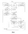
- FIG. 1is a block diagrammatic view of the control system of the present disclosure
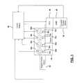
- FIG. 2is a block diagrammatic view of a control module according to the present disclosure
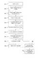
- FIG. 3is a flowchart of a method for operating an engine using in-cylinder pressure sensors
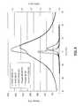
- FIG. 4is a plot of a filtered pressure signal
- FIG. 5is a plot of pressure versus crank angle for various heat releases and pressures at various ends of injections (EOIs).
- FIG. 6is a plot of pressure versus crank for the top-dead-center area for various pressures and the rate of heat releases around top-dead-center.
- FIG. 7is a plot of pressure and rate of heat release for a 45° and 360° end of injection for a re-breathing mode.
- modulerefers to an Application Specific Integrated Circuit (ASIC), an electronic circuit, a processor (shared, dedicated, or group) and memory that execute one or more software or firmware programs, a combinational logic circuit, and/or other suitable components that provide the described functionality.
- ASICApplication Specific Integrated Circuit
- processorshared, dedicated, or group
- memorythat execute one or more software or firmware programs, a combinational logic circuit, and/or other suitable components that provide the described functionality.
- an engine 10may include in-cylinder pressure sensors 30 A, 30 B, 30 C and 30 D in respective cylinders 32 A- 32 D.
- Each in-cylinder pressure sensor 30 A- 30 Dgenerates an in-cylinder pressure signal that is communicated to a control module 40 .
- the control module 40may be an engine control module. Although only four cylinders 30 A- 30 D are shown, the engine may include many different numbers of cylinders and corresponding pressure sensors.
- the engine 10may be a variable valve timing engine that includes an oil control valve (OCV) 46 used to control switchable roller finger followers 48 .
- OCVoil control valve
- the present disclosuremay apply to various other types of engines.
- the control module 40may include a controller for the oil control valve 46 that is used to control the flow of oil that is used to control the switchable roller finger followers 48 .
- a camshaft position sensor 50may also provide an angular position signal to the control module 40 .
- the camshaft position sensorindicates a position and thus the expected valve position for valves 52 a - 52 d .
- a fault in the camshaft position sensor 50may be determined.
- the control module 40thus indirectly controls the operation of valves 52 a , 52 b , 52 c and 52 d and can determine the stability of operation thereof. Although only one valve is illustrated for simplicity, each cylinder includes at least one intake valve and at least one exhaust valve. Multiple intake and exhaust valves may also be provided.
- the control module 40may manage the torque of the engine and generate pressure-volume curves corresponding to the operation of the engine.
- the control module 40may be used to generate a mean effective pressure (MEP) using the pressure sensors 30 A- 30 D.
- the mean effective pressuremay be used to calculate the heat released which in turn may be used to generate a determination of the amount of fuel burned during a recompression cycle in an HCCI engine.
- the amount of fuel burnedmay provide an indication of the remaining fuel that is ready to be burned.
- the amount of fuel burnedmay also be used to control the amount of oxides of nitrogen generated from the combustion process within the cylinders.
- An angular position sensor 54may generate an angular position signal corresponding to the angular position of the crankshaft of the engine.
- the angular position of the crankshaftcorresponds to the piston position.
- the angular position signalmay be provided to the control module 40 . More than one of the angular position sensor signal and the magnitude or amplitude of the pressure sensor signal may be used by the control module in determining filter coefficients for filtering the pressure sensor signals as will be described below.
- the angular position sensor 54may not provide the resolution required for precise control in an HCCI engine.
- the absolute zero torque positionmay be generated with further resolution.
- absolute zero torque positionmay yield the top-dead-center of the cylinder.
- the top-dead-centermay be resolved to about 0.2 to 0.4 degrees. This will allow more precise control of the HCCI process.
- the control module 40may include a pressure signal generator module 120 .
- Each of the pressure sensors 30 A- 30 Dmay be used to generate a pressure signal.
- the pressure signal generator module 120may receive the pressure signals from the pressure sensors and convert them into a form usable by other modules within the control module. As will be described below, each of the pressure signals from each of the cylinders may be used.
- a filter module 122is used to filter the pressure signals from the pressure signal generator module 120 .
- filtersmay be used.
- the filter module 122may include a finite impulse response digital filter having various coefficients.
- an infinite impulse response filtermay be used.
- the filter module 122may receive filter coefficients from a filter coefficient determination module 124 .
- the filter coefficient determination module 124may generate filter coefficients based upon various engine operating conditions.
- the engine operating conditionsmay include determining a torque or engine load.
- the load-determination modulemay determine the engine load or torque based upon various inputs such as an accelerator pedal input.
- the filter coefficient determination module 124may vary the filter coefficients based upon the load (torque) of the engine.
- the filter coefficientsmay be changed during various loading conditions.
- the filter coefficientsmay be changed.
- the filter coefficientsmay be varied.
- the filter coefficientsmay be changed from a first set to a second set when the load (torque), position or magnitude increases above a threshold and changes back to the first set of coefficients when below the threshold.
- several thresholdsmay be provided at various intervals of load, pressure signal amplitude or angular position.
- the filter coefficientsmay be relaxed or changed at 20 degrees before top-dead-center and resume normal operation 60 degrees after top-dead-center. This provides operation for two different sets of coefficients based on position of the crankshaft.
- the relaxation in the filter coefficientsmay be configured to shift the filter gain by three decibels.
- Optimum filter values and positionsmay be determined based upon engine calibrations.
- the filter coefficientsmay be calibrated during the development of the engine.
- the filter coefficientsmay be obtained from a look-up table or calculated during the engine operation process.
- a window module 126may receive the filtered pressure signals.
- the window module 126may be in communication with an angular engine position module 128 .
- the angular engine position module 128may provide angular engine position signals to the window module 126 .
- the angular positioncorresponds to the position of the cylinders within the engine.
- the window module 126may provide pressure signals that are within a window or range of engine or piston positions to a mean effective pressure determination module 130 . Pressure signals that fall outside of the window may not be used in mean effective pressure calculation.
- One example of the piston position windowis between 90° before top-dead-center and 90° after top-dead-center.
- the window module 126can also be set to be smaller such as between 60° below top-dead-center and 60° after top-dead-center.
- the windowmay even be made smaller such as between 50° below top-dead-center and 50° after top-dead-center.
- the window sizemay vary depending on the amount of noise present in the pressure signals from each cylinder.
- the window sizemay be set during a calibration procedure and stored within a memory of the control module 40 from the manufacturer of the vehicle.
- the mean effective pressure determination module 130may generate a mean effective pressure based upon the pressure signals within the window.
- the Cylinder Pressure measured at the start of the determined window and at the end of this windowmay also be used to enhance the reformation burn MEP calculation by using the ratio of the cylinder volume swept during the unmeasured window, to the entire swept volume of the cylinder. (Pend ⁇ Pstart) ⁇ Unmeasured Swept Volume/Total Swept engine Volume, added to the iterative calculation of MEP during reformation.
- the mean effective pressure determination module 130may be used to determine the top-dead-center (TDC) in the top-dead-center determination module 134 .
- the top-dead-center determination module 134may use the mean effective pressure to determine a zero torque position that corresponds to the top-dead-center.
- the top-dead-center determinationmay be more accurate than that of the crank shaft position sensor. For example, resolution to between about 0.2° and 0.4° was achieved in a test vehicle.
- the mean effective pressure determination module 130may also communicate the mean effective pressure signal to a heat released determination module 140 .
- the heat released determination module 140may communicate the heat release determination to the engine control module 154 for further control.
- the heat released determination module 140may also provide the heat released to a fuel burned during recompression module 152 .
- the fuel burned during recompressionmay be detected using the heat released.
- the exhaust valveis closed earlier so that the trapped exhaust is recompressed as the cylinder approaches top-dead-center.
- Fuelmay be injected during recompression. Because the volume and pressure are known, the amount of heat released may be determined. The amount of fuel burned may correspond directly to the heat released.
- the heat released during recompressionmay be less than one joule per degree of crank shaft angle.
- the amount of fuel ready to burn module 154may determine an amount of fuel that is ready to be burned after the fuel burned during recompression is determined. The amount of fuel injected into the cylinder is known so therefore by subtracting the fuel burned during the recompression the amount of fuel that is ready to be burned may be generated.
- the engine control module 150may use the fuel burned during recompression or the amount of fuel ready to burn or both in controlling various engine functions. The engine functions being controlled may include the timing of fuel injection, the timing of spark, or both.
- step 210the engine is operated.
- step 212the engine operating conditions are determined. As mentioned above, the load may be determined and the amplitude of the pressure signals may be determined.
- the filter coefficientsmay be generated based upon the engine operating conditions in step 214 .
- the filter coefficientsmay vary based upon one or more of the load, angular position or the amplitude of the pressure signal.
- step 216the pressure signal from the pressure sensor is generated. As described above, more than one pressure signal may be generated. Also, one pressure signal per cylinder may be generated.
- the pressure signalis filtered to form a filtered pressure signal based upon the filter coefficients.
- the filtermay be a finite impulse response (FIR) filter or an infinite impulse response (IIR) filter.
- FIRfinite impulse response
- IIRinfinite impulse response
- other types of filters having digital coefficientsmay be used.
- the cylinder positionmay be determined.
- the cylinder positionmay be determined using the crank angle.
- a cylinder position windowmay be defined.
- the cylinder position windowmay be defined so that low noise pressure signals are used for the following calculations.
- the cylinder windowas described above, may be various sizes including a predetermined amount before and after top-dead-center. For example, a cylinder window 90° before top-dead-center and 90° after top-dead-center may be used. Likewise, 60° both before and after top-dead-center and 50° below top-dead-center may be used. The width of the window may vary depending upon the characteristics of the engine and the operating noise within the engine.
- the mean effective pressure using pressure signals that fall within the cylinder position windowis determined.
- the enginemay be controlled using the mean effective pressure.
- the enginemay be controlled with a top-dead-center determination using the mean effective pressure in step 228 . This process was described above.
- the enginemay also control other functions including determining heat released during a recompression mode in step 230 .
- the amount of fuel crackingmay be determined in step 232 .
- Fuel crackingis generally used to describe the amount of fuel that is ready to be burned.
- the amount of fuel cracking in step 232may be determined.
- the amount of fuel crackingmay be used to control the amounts of oxides of nitrogen generated in the combustion process.
- noise suppressionhas been provided with coefficients based upon the position of the crankshaft.
- a line 410 corresponding to 300 kilopascalsis provided on the graph.
- the line 410corresponds to crank angles within the window.
- the less noisy peak signalmay be used in the calculation of heat released and mean effective pressure.
- the rate of heat release and pressureis plotted for various cylinder positions between 450° and 270° before top-dead-center with different end of injections (EOI).
- FIG. 7a work cycle burn illustrating different re-breathing pressures and re-breathing rate of heat release versus engine position is illustrated. As can be seen, the fuel burn may vary depending on the end of injection.
- FIG. 6is a plot similar to FIG. 5 except the cylinder position shown is between 90° before top-dead-center and 90° after top-dead-center.
Landscapes
- Engineering & Computer Science (AREA)
- Chemical & Material Sciences (AREA)
- Combustion & Propulsion (AREA)
- Mechanical Engineering (AREA)
- General Engineering & Computer Science (AREA)
- Combined Controls Of Internal Combustion Engines (AREA)
- Electrical Control Of Air Or Fuel Supplied To Internal-Combustion Engine (AREA)
Abstract
Description
Claims (16)
Priority Applications (3)
| Application Number | Priority Date | Filing Date | Title |
|---|---|---|---|
| US12/609,407US8510016B2 (en) | 2009-10-30 | 2009-10-30 | Method and system for controlling an engine using in-cylinder pressure sensor signals |
| DE102010049529.8ADE102010049529B4 (en) | 2009-10-30 | 2010-10-25 | System for controlling an engine using in-cylinder pressure sensor signals |
| CN201010531299.5ACN102052188B (en) | 2009-10-30 | 2010-10-29 | In-cylinder pressure sensor signal is used to control the method and system of motor |
Applications Claiming Priority (1)
| Application Number | Priority Date | Filing Date | Title |
|---|---|---|---|
| US12/609,407US8510016B2 (en) | 2009-10-30 | 2009-10-30 | Method and system for controlling an engine using in-cylinder pressure sensor signals |
Publications (2)
| Publication Number | Publication Date |
|---|---|
| US20110106394A1 US20110106394A1 (en) | 2011-05-05 |
| US8510016B2true US8510016B2 (en) | 2013-08-13 |
Family
ID=43902264
Family Applications (1)
| Application Number | Title | Priority Date | Filing Date |
|---|---|---|---|
| US12/609,407Expired - Fee RelatedUS8510016B2 (en) | 2009-10-30 | 2009-10-30 | Method and system for controlling an engine using in-cylinder pressure sensor signals |
Country Status (3)
| Country | Link |
|---|---|
| US (1) | US8510016B2 (en) |
| CN (1) | CN102052188B (en) |
| DE (1) | DE102010049529B4 (en) |
Cited By (1)
| Publication number | Priority date | Publication date | Assignee | Title |
|---|---|---|---|---|
| US20170184048A1 (en)* | 2015-12-24 | 2017-06-29 | Mazda Motor Corporation | Fuel injection control method and fuel injection control device for compression self-ignition engine |
Families Citing this family (6)
| Publication number | Priority date | Publication date | Assignee | Title |
|---|---|---|---|---|
| US8561592B2 (en)* | 2009-06-08 | 2013-10-22 | GM Global Technology Operations LLC | Method and system for generating an in-cylinder pressure sensor signal |
| JP5579787B2 (en)* | 2012-06-19 | 2014-08-27 | 本田技研工業株式会社 | Control device for internal combustion engine |
| CN102817738B (en)* | 2012-08-31 | 2016-05-04 | 长城汽车股份有限公司 | A kind of hcci engine Detection & Controling method of catching fire |
| US20140172277A1 (en)* | 2012-12-18 | 2014-06-19 | Caterpillar Inc. | Engine diagnostic system and method |
| JP6773762B2 (en)* | 2015-04-07 | 2020-10-21 | キャロット,インコーポレイテッド | Systems and methods for quantifying and predicting smoking behavior |
| US11524395B2 (en)* | 2018-04-10 | 2022-12-13 | Panasonic Intellectual Property Management Co., Ltd. | Signal processing apparatus and electric tool |
Citations (10)
| Publication number | Priority date | Publication date | Assignee | Title |
|---|---|---|---|---|
| US5076098A (en)* | 1990-02-21 | 1991-12-31 | Nissan Motor Company, Limited | System for detecting combustion state in internal combustion engine |
| US5738074A (en)* | 1995-10-02 | 1998-04-14 | Yamaha Hatsudoki Kabushiki Kaisha | Engine control system and method |
| US20020026926A1 (en)* | 1996-08-23 | 2002-03-07 | Loye Axel O. Zur | Premixed charge compression ignition engine with optimal combustion control |
| US20050211219A1 (en)* | 2002-12-30 | 2005-09-29 | Hans Strom | Method for auto-ignition operation and computer readable storage device for use with an internal combustion engine |
| US20060293829A1 (en)* | 2002-11-27 | 2006-12-28 | Cornwell Richard Charles E | Engine management |
| US20070021903A1 (en)* | 2005-07-14 | 2007-01-25 | Urs Christen | Method for monitoring combustion stability of an internal combustion engine |
| US20070142937A1 (en)* | 2005-12-19 | 2007-06-21 | Honda Motor Co. Ltd. | Control apparatus |
| US20070271025A1 (en)* | 2003-11-14 | 2007-11-22 | Honda Motors Co., Ltd. | Ignition Timing Controlling Device and Method |
| US20090112449A1 (en)* | 2005-12-09 | 2009-04-30 | Simon Binder | Method of controlling an internal combustion engine, in particular a diesel engine |
| US7788022B2 (en)* | 2008-05-12 | 2010-08-31 | Mitsubishi Electric Corporation | Control apparatus for internal combustion engine |
Family Cites Families (2)
| Publication number | Priority date | Publication date | Assignee | Title |
|---|---|---|---|---|
| DE10218736A1 (en)* | 2002-04-26 | 2003-11-13 | Volkswagen Ag | Diesel engine regulation method detects combustion pressure for calculation of effective engine torque used for regulation of at least one engine operating parameter |
| DE102004044339A1 (en)* | 2004-09-09 | 2006-03-16 | Robert Bosch Gmbh | Method for correcting a measured cylinder pressure of an internal combustion engine |
- 2009
- 2009-10-30USUS12/609,407patent/US8510016B2/ennot_activeExpired - Fee Related
- 2010
- 2010-10-25DEDE102010049529.8Apatent/DE102010049529B4/ennot_activeExpired - Fee Related
- 2010-10-29CNCN201010531299.5Apatent/CN102052188B/ennot_activeExpired - Fee Related
Patent Citations (12)
| Publication number | Priority date | Publication date | Assignee | Title |
|---|---|---|---|---|
| US5076098A (en)* | 1990-02-21 | 1991-12-31 | Nissan Motor Company, Limited | System for detecting combustion state in internal combustion engine |
| US5738074A (en)* | 1995-10-02 | 1998-04-14 | Yamaha Hatsudoki Kabushiki Kaisha | Engine control system and method |
| US20020026926A1 (en)* | 1996-08-23 | 2002-03-07 | Loye Axel O. Zur | Premixed charge compression ignition engine with optimal combustion control |
| US20060293829A1 (en)* | 2002-11-27 | 2006-12-28 | Cornwell Richard Charles E | Engine management |
| US20090158831A1 (en)* | 2002-11-27 | 2009-06-25 | Richard Charles Elliot Cornwell | Engine Management |
| US20050211219A1 (en)* | 2002-12-30 | 2005-09-29 | Hans Strom | Method for auto-ignition operation and computer readable storage device for use with an internal combustion engine |
| US20070271025A1 (en)* | 2003-11-14 | 2007-11-22 | Honda Motors Co., Ltd. | Ignition Timing Controlling Device and Method |
| US20070021903A1 (en)* | 2005-07-14 | 2007-01-25 | Urs Christen | Method for monitoring combustion stability of an internal combustion engine |
| US20090112449A1 (en)* | 2005-12-09 | 2009-04-30 | Simon Binder | Method of controlling an internal combustion engine, in particular a diesel engine |
| US8032293B2 (en)* | 2005-12-09 | 2011-10-04 | Daimler A.G. | Method of controlling an internal combustion engine, in particular a diesel engine |
| US20070142937A1 (en)* | 2005-12-19 | 2007-06-21 | Honda Motor Co. Ltd. | Control apparatus |
| US7788022B2 (en)* | 2008-05-12 | 2010-08-31 | Mitsubishi Electric Corporation | Control apparatus for internal combustion engine |
Cited By (2)
| Publication number | Priority date | Publication date | Assignee | Title |
|---|---|---|---|---|
| US20170184048A1 (en)* | 2015-12-24 | 2017-06-29 | Mazda Motor Corporation | Fuel injection control method and fuel injection control device for compression self-ignition engine |
| US10012174B2 (en)* | 2015-12-24 | 2018-07-03 | Mazda Motor Corporation | Fuel injection control method and fuel injection control device for compression self-ignition engine |
Also Published As
| Publication number | Publication date |
|---|---|
| CN102052188A (en) | 2011-05-11 |
| DE102010049529A1 (en) | 2011-05-26 |
| DE102010049529B4 (en) | 2017-06-29 |
| CN102052188B (en) | 2016-02-24 |
| US20110106394A1 (en) | 2011-05-05 |
Similar Documents
| Publication | Publication Date | Title |
|---|---|---|
| US8510016B2 (en) | Method and system for controlling an engine using in-cylinder pressure sensor signals | |
| US7594493B2 (en) | Method for controlling fuel injection in a compression ignition engine | |
| US8342011B2 (en) | Method for determining a value representative of the pressure in a combustion chamber of an internal combustion engine | |
| EP1862670B1 (en) | Ignition timing control apparatus and method for internal combustion engine | |
| KR100791163B1 (en) | Fuel injection control device for internal combustion engines | |
| US9394836B2 (en) | Internal combustion engine control apparatus | |
| JP6350432B2 (en) | Control device for internal combustion engine | |
| US8965666B2 (en) | Knock control device for engine | |
| JP6362713B2 (en) | Knock detection device | |
| CN101233308A (en) | Internal Combustion Engine Control Equipment | |
| JP2004515685A (en) | Internal combustion engine control method | |
| CN102444525A (en) | Knock control device for internal combustion engine | |
| WO2011155054A1 (en) | Control device for internal combustion engine | |
| JP2005291182A (en) | Misfire detection device | |
| WO2012147193A1 (en) | Control device for internal-combustion engine | |
| WO2014061649A1 (en) | In-cylinder pressure detection device for internal combustion engine | |
| WO2013069157A1 (en) | Intra-cylinder pressure sensor fault diagnostic device and intra-cylinder sensor sensitivity correction device provided with same | |
| US7644608B2 (en) | Intake air temperature sensor diagnostic | |
| US20130218443A1 (en) | Knock control device of internal combustion engine | |
| US20130245924A1 (en) | Internal combustion engine knock controlling apparatus | |
| KR101358167B1 (en) | Method and device for operating an internal combustion engine | |
| US20130192343A1 (en) | Knock detection device of internal combustion engine | |
| US8561592B2 (en) | Method and system for generating an in-cylinder pressure sensor signal | |
| CA2525020C (en) | A combustion state detecting apparatus for an engine | |
| JP5072203B2 (en) | Measuring method of combustion chamber pressure |
Legal Events
| Date | Code | Title | Description |
|---|---|---|---|
| AS | Assignment | Owner name:GM GLOBAL TECHNOLOGY OPERATIONS, INC., MICHIGAN Free format text:ASSIGNMENT OF ASSIGNORS INTEREST;ASSIGNORS:BUSLEPP, KENNETH J.;VERNER, DOUGLAS R.;REEL/FRAME:023518/0862 Effective date:20091019 | |
| AS | Assignment | Owner name:UAW RETIREE MEDICAL BENEFITS TRUST, MICHIGAN Free format text:SECURITY AGREEMENT;ASSIGNOR:GM GLOBAL TECHNOLOGY OPERATIONS, INC.;REEL/FRAME:023990/0001 Effective date:20090710 Owner name:UNITED STATES DEPARTMENT OF THE TREASURY, DISTRICT Free format text:SECURITY AGREEMENT;ASSIGNOR:GM GLOBAL TECHNOLOGY OPERATIONS, INC.;REEL/FRAME:023989/0155 Effective date:20090710 | |
| AS | Assignment | Owner name:GM GLOBAL TECHNOLOGY OPERATIONS, INC., MICHIGAN Free format text:RELEASE BY SECURED PARTY;ASSIGNOR:UNITED STATES DEPARTMENT OF THE TREASURY;REEL/FRAME:025246/0234 Effective date:20100420 | |
| AS | Assignment | Owner name:GM GLOBAL TECHNOLOGY OPERATIONS, INC., MICHIGAN Free format text:RELEASE BY SECURED PARTY;ASSIGNOR:UAW RETIREE MEDICAL BENEFITS TRUST;REEL/FRAME:025315/0136 Effective date:20101026 | |
| AS | Assignment | Owner name:WILMINGTON TRUST COMPANY, DELAWARE Free format text:SECURITY AGREEMENT;ASSIGNOR:GM GLOBAL TECHNOLOGY OPERATIONS, INC.;REEL/FRAME:025324/0555 Effective date:20101027 | |
| AS | Assignment | Owner name:GM GLOBAL TECHNOLOGY OPERATIONS LLC, MICHIGAN Free format text:CHANGE OF NAME;ASSIGNOR:GM GLOBAL TECHNOLOGY OPERATIONS, INC.;REEL/FRAME:025781/0299 Effective date:20101202 | |
| FEPP | Fee payment procedure | Free format text:PAYOR NUMBER ASSIGNED (ORIGINAL EVENT CODE: ASPN); ENTITY STATUS OF PATENT OWNER: LARGE ENTITY | |
| STCF | Information on status: patent grant | Free format text:PATENTED CASE | |
| AS | Assignment | Owner name:GM GLOBAL TECHNOLOGY OPERATIONS LLC, MICHIGAN Free format text:RELEASE BY SECURED PARTY;ASSIGNOR:WILMINGTON TRUST COMPANY;REEL/FRAME:034287/0001 Effective date:20141017 | |
| FPAY | Fee payment | Year of fee payment:4 | |
| FEPP | Fee payment procedure | Free format text:MAINTENANCE FEE REMINDER MAILED (ORIGINAL EVENT CODE: REM.); ENTITY STATUS OF PATENT OWNER: LARGE ENTITY | |
| LAPS | Lapse for failure to pay maintenance fees | Free format text:PATENT EXPIRED FOR FAILURE TO PAY MAINTENANCE FEES (ORIGINAL EVENT CODE: EXP.); ENTITY STATUS OF PATENT OWNER: LARGE ENTITY | |
| STCH | Information on status: patent discontinuation | Free format text:PATENT EXPIRED DUE TO NONPAYMENT OF MAINTENANCE FEES UNDER 37 CFR 1.362 | |
| FP | Lapsed due to failure to pay maintenance fee | Effective date:20210813 |