US8509886B2 - Cardiac monitoring system - Google Patents
Cardiac monitoring systemDownload PDFInfo
- Publication number
- US8509886B2 US8509886B2US13/305,606US201113305606AUS8509886B2US 8509886 B2US8509886 B2US 8509886B2US 201113305606 AUS201113305606 AUS 201113305606AUS 8509886 B2US8509886 B2US 8509886B2
- Authority
- US
- United States
- Prior art keywords
- characteristic frequency
- subject
- impedance
- determined
- cardiac
- Prior art date
- Legal status (The legal status is an assumption and is not a legal conclusion. Google has not performed a legal analysis and makes no representation as to the accuracy of the status listed.)
- Expired - Fee Related
Links
Images


Classifications
- A—HUMAN NECESSITIES
- A61—MEDICAL OR VETERINARY SCIENCE; HYGIENE
- A61B—DIAGNOSIS; SURGERY; IDENTIFICATION
- A61B5/00—Measuring for diagnostic purposes; Identification of persons
- A61B5/02—Detecting, measuring or recording for evaluating the cardiovascular system, e.g. pulse, heart rate, blood pressure or blood flow
- A61B5/026—Measuring blood flow
- A61B5/029—Measuring blood output from the heart, e.g. minute volume
- A—HUMAN NECESSITIES
- A61—MEDICAL OR VETERINARY SCIENCE; HYGIENE
- A61B—DIAGNOSIS; SURGERY; IDENTIFICATION
- A61B5/00—Measuring for diagnostic purposes; Identification of persons
- A61B5/02—Detecting, measuring or recording for evaluating the cardiovascular system, e.g. pulse, heart rate, blood pressure or blood flow
- A61B5/02028—Determining haemodynamic parameters not otherwise provided for, e.g. cardiac contractility or left ventricular ejection fraction
- A—HUMAN NECESSITIES
- A61—MEDICAL OR VETERINARY SCIENCE; HYGIENE
- A61B—DIAGNOSIS; SURGERY; IDENTIFICATION
- A61B5/00—Measuring for diagnostic purposes; Identification of persons
- A61B5/02—Detecting, measuring or recording for evaluating the cardiovascular system, e.g. pulse, heart rate, blood pressure or blood flow
- A61B5/026—Measuring blood flow
- A61B5/0295—Measuring blood flow using plethysmography, i.e. measuring the variations in the volume of a body part as modified by the circulation of blood therethrough, e.g. impedance plethysmography
- A—HUMAN NECESSITIES
- A61—MEDICAL OR VETERINARY SCIENCE; HYGIENE
- A61B—DIAGNOSIS; SURGERY; IDENTIFICATION
- A61B5/00—Measuring for diagnostic purposes; Identification of persons
- A61B5/05—Detecting, measuring or recording for diagnosis by means of electric currents or magnetic fields; Measuring using microwaves or radio waves
- A61B5/053—Measuring electrical impedance or conductance of a portion of the body
- A61B5/0535—Impedance plethysmography
Definitions
- the present inventionrelates to methods and apparatuses for monitoring biological parameters, and in particular to a method and apparatus for measuring cardiac function in a subject using bioelectric impedance or components of bioelectric impedance.
- Cardiac outputwhich can be defined as the amount of blood ejected by the ventricles of the heart per minute (measured in liters per minute), is governed by the metabolic demands of the body, and therefore reflect the status of the entire circulatory system. For this reason measurement of cardiac output is an essential aspect of haemodynamic monitoring of patients with heart disease or who are recovering from various forms of cardiovascular disease or other medical treatments.
- Impedance cardiographyinvolves measuring the electrical impedance of a subject's body using a series of electrodes placed on the skin surface. Changes in electrical impedance at the body's surface are used to determine changes in tissue volume that are associated with the cardiac cycle, and accordingly, measurements of cardiac output and other cardiac function.
- a complication in impedance cardiographyis that the baseline impedance of the thorax varies considerably between individuals, the quoted range for an adult is 20 ⁇ -48 ⁇ at a frequency between 50 kHz-100 kHz.
- the changes in impedance due to the cardiac cycleare a relatively small (0.5%) fraction of the baseline impedance, which leads to a very fragile signal with a low signal to noise ratio.
- the equivalent circuitincludes an intracellular branch formed from a capacitance C representing the capacitance of the cell membranes in the intracellular pathway and the resistance R I representing the resistance of the intracellular fluid.
- the circuitalso includes an extracellular branch formed from resistance R E which represents the conductive pathway through the tissue.
- WO2004/032738operates based on the assumption that the cardiac cycle will only have an impact on the volume of extracellular fluid in the patient's thorax, and therefore that cardiac function can be derived by considering changes in the extracellular component of the impedance. This is achieved by applying an alternating current at a number of different frequencies. The impedance is measured at each of these frequencies and then extrapolated to determine the impedance at zero applied frequency, which therefore corresponds to the resistance R E . This is then determined to be solely due to the extracellular fluid component and hence can be used to determine attributes of cardiac function, such as stroke volume.
- the impedance at zero frequencywould not be due solely to extracellular fluids but would be influenced by a number of other factors.
- cellsdo not act as a perfect capacitor and accordingly, the intracellular fluid will contribute to the impedance at a zero applied frequency.
- these methodsmay involve determining an actual characteristic frequency, measuring the instantaneous impedance or components of the impedance at that characteristic frequency, and using the instantaneous impedance (or a component of the impedance) values(s) to determine a measure of cardiac function.
- a characteristic frequencymay be determined by analyzing the bioelectric response of the subject's body or tissue at various frequencies, as described in greater detail herein.
- An impedance(or a component of the impedance such as reactance, phase shift, magnitude, resistance) may be measured either directly or derived.
- a characteristic frequencymay be determined for a particular subject either once, or periodically. For example, each measurement of instantaneous impedance may be made at a new characteristic frequency. This is described in greater detail below.
- One variation of a method of determining a measure of cardiac function in a subjectmay include the steps of determining a characteristic frequency for the subject, determining the impedance or a component of the impedance at the characteristic frequency, and determining a measure of cardiac function using the impedance or a component of the impedance determined at the characteristic frequency.
- the characteristic frequency of the subjectis determined by applying an electrical signal having a plurality of frequencies to the subject, determining an instantaneous impedance value at each of the plurality of frequencies, fitting the instantaneous impedance values to a frequency dependent function, and determining the characteristic frequency using the function.
- the characteristic frequencymay be determined from an approximate maximum of the function.
- the frequency dependent functionmay be a function based on a Wessel plot or a Cole plot, or a polynomial curve fit.
- the characteristic frequencymay be determined over any appropriate frequency range.
- the characteristic frequencymay be determined by applying an electrical signal having a plurality of frequencies within the range of 2-10,000 kHz to the subject.
- the impedance (or a component of the impedance) at the characteristic frequencyis determined by comparing an electrical signal applied to the subject (having a frequency at approximately the characteristic frequency) with an electrical signal received from the subject in response to the applied electrical signal.
- the component of impedance determinedmay be the reactance, the phase (e.g., phase shift) or the magnitude.
- the reactance or the phase shift values measured at the characteristic frequencymay be used to measure (or estimate) a characteristic cardiac function.
- multiple (“instantaneous”) values for the impedance or a component of the impedancemay be determined during the course of a cardiac cycle.
- any appropriate measure of cardiac functionmay be determined using the characteristic frequency, including stroke volume and cardiac output.
- stroke volumemay be determined by multiplying the maximum change in impedance during a cardiac cycle by one or more constants including constants based on the subject's physical characteristics.
- the measure of cardiac functionmay be determined using the impedance (or a component of the impedance) at the characteristic frequency for a number of sequential time points.
- instantaneous reactance valuesmay be taken during an entire (or a portion of a) cardiac cycle.
- the same characteristic frequencymay be used to determine the instantaneous impedance values used to determine the measure of cardiac function, or the characteristic frequency may be repeatedly determined for each time point or a subset of time points.
- the measure of cardiac functionmay be determined by determining the characteristic frequency and the instantaneous reactance at the characteristic frequency for a number of sequential time points.
- Also described herein are methods of determining a measure of cardiac output in a subjectincluding the steps of applying an electrical signal having a plurality of frequencies to the subject, receiving an electrical signal from the subject in response to the applied signal, determining a characteristic frequency for the subject by comparing the applied and received electrical signals, determining at least one component of the impedance at the characteristic frequency, and determining a measure of cardiac function using the at least one component of the impedance determined at the characteristic frequency.
- the characteristic frequencymay be determined by comparing the applied and received electrical signals to determine an instantaneous impedance value and fitting the instantaneous impedance values to a frequency dependent function.
- the at least one component of the impedance determined at the characteristic frequencymay be the reactance, the phase (e.g., phase shift), the magnitude, or the resistance.
- any appropriate measure of cardiac functionmay be determined, including stroke volume and/or cardiac output.
- indicia of cardiac functionmay be determined by first identifying the characteristic frequency, and then determining the instantaneous reactance values at the characteristic frequency for a number of sequential time points (e.g., during a full cardiac cycle).
- a measure of cardiac functionmay be determined by determining the instantaneous phase shift values at the characteristic frequency for a number of sequential time points during a cardiac cycle.
- the measure of cardiac functionmay be determined by determining the characteristic frequency and at least one component of the impedance at the characteristic frequency for a number of sequential time points during a cardiac cycle.
- These systemsmay include a plurality of electrodes configured to be attached to a subject, and a processor connected to the plurality of electrodes.
- the processormay be configured to control the application of an electrical signal having a plurality of frequencies to the subject, receive an electrical signal from the subject in response to the applied signal, determine a characteristic frequency by comparing the applied and received electrical signals, determine at least one component of the impedance at the characteristic frequency, and determine a measure of cardiac function using the at least one component of the impedance determined at the characteristic frequency.
- the systemalso includes a signal generator coupled to processor for generating the electrical signals applied to the subject.
- the systemsmay also include one or more sensors for detecting the electrical signals from the subject in response to the applied electrical signals.
- the systemmay also include processing logic for determining the measure of cardiac output by multiplying the at least one component of the impedance (e.g., reactance, phase shift) by one or more constants including constants based on the subject's physical characteristics.
- the processing logicmay be implemented by software, hardware, or any combination of these.
- the processormay be a microprocessor configured to execute the processing logic.
- any of the systems described hereinmay also include one or more input devices in communication with the processor for entering at least some of the subject's physical characteristics.
- the systemsmay include a keypad, mouse, memory, wireless connection or the like for receiving input.
- Physical characteristicsmay include height, gender, weight, pulse rate, age, ethnicity, etc.
- FIG. 1is a schematic of an example of an equivalent circuit used to model the conduction characteristics of biological tissue.
- FIG. 2is a flowchart of an example of a process for determining cardiac function.
- FIGS. 3A and 3Bare schematics of an example of the effects of blood flow on blood cell orientation.
- FIG. 4is a schematic of a second example of an equivalent circuit used to model the conduction characteristics of biological tissue.
- FIG. 5is a schematic of an example of apparatus for determining cardiac function.
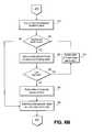
- FIGS. 6A to 6Care a flowchart of a second example of a process for determining cardiac function.
- FIG. 7is an example of a graph of impedance plotted against frequency for an impedance measurement.
- FIG. 8is an example of a Wessel diagram of susceptance plotted against conductance.
- FIG. 9is an example of three plots depicting the time varying impedance of the thorax, the level of impedance change due to cardiac function and an ECG.
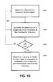
- FIG. 10is an exemplary flowchart of an example of a process for determining cardiac function.
- FIG. 11is another exemplary flowchart of an example of a process for determining cardiac function.
- FIG. 2An example of a process for determining parameters of cardiac function relating to a subject is described with reference to FIG. 2 .
- alternating electrical signalsare applied to the subject at a number of different frequencies f i , with electrical signals across the subject being detected at each of the respective f i , at step 110 .
- the nature of the signals applied and detectedwill depend on the implementation as will be described below.
- the impedance Z i at each frequency f iis determined.
- the impedanceis used to determine an intracellular impedance parameter at the time t n . In one example, this is achieved utilising an appropriate model, such as a CPE (constant phase element) model, which will be described in more detail below.
- CPEconstant phase element
- Thismay be achieved by monitoring appropriate ECG signals, or alternatively simply by processing sufficient time instances to ensure that a cardiac cycle has been detected.
- the intracellular impedance parameterand in one example, changes in the intracellular impedance parameter, is used to determine cardiac parameters.
- This techniquetakes into account that the impedance fluctuation of the thorax during the cardiac cycle is dependent on both changes in blood volume and changes in the impedance in the blood itself.
- Bloodis a suspension of erythrocytes, with a high resistivity, and other cells in a conducting fluid called plasma.
- the erythrocytes of stationary bloodare randomly orientated as shown in FIG. 3A , and hence the resistivity of stationary blood is isotropic. Due to their biconcave shape erythrocytes tend to align themselves in flowing blood with their axes parallel to the direction of flow as shown in FIG. 3B . Accordingly, the resistivity of flowing blood is anisotropic.
- the anisotropy of the resistivityis due to the longer effective path length for the current travelling normal to the axis of the vessel compared with the current flowing parallel to the vessel.
- the resistance of the intracellular fluidalters depending on the orientation of the erythrocytes, and hence depends on the flow of blood.
- the extent of the anisotropyis shear-rate dependent since the orientation of the erythrocytes is influenced by the viscous forces in flowing blood. As a result, the resistivity is in turn also dependent on the flow rate.
- the impedance measurementscan be used to determine values for the intracellular resistance R I and the capacitance C, for example, by determining values of R 0 and R ⁇ , and then using these to solve the Cole equation using appropriate mathematical techniques.
- modelling the resistivity as a constant valuedoes not accurately reflect the impedance response of a subject, and in particular does not accurately model the change in orientation of the erythrocytes, or other relaxation effects.
- an equivalent circuit based on a free conductance parallel modelis used, as shown in FIG. 4 .
- Such a modelcan also be created in a series form and the parallel model is shown here for illustration.
- the circuitincludes an extracellular conductance G 0 that represents the conductance of electrical current through the extracellular fluid.
- the intracellular conduction pathincludes a constant phase element (CPE) represented as the series connection of a frequency dependent conductance, and a frequency dependent capacitance.
- CPEconstant phase element
- ⁇ cpearctan ⁇ ⁇ B G ( 2 )
- Y CPEis the admittance of the CPE
- ⁇ cpeis the phase of the CPE.
- ⁇represents a frequency scale factor and, ⁇ is dimensionless.
- the parameter mdefines the extent of the frequency dependence of the admittance of the CPE Y CPE and the frequency scale factor with ⁇ . It is known that for biological tissue m is in the range of 0 ⁇ m ⁇ 1.
- the series ideal resistoris changed to a free resistor parameter R var so that the characteristic time constant ⁇ z will be a dependent parameter.
- YG 0 + 1 R var + R 1 ⁇ ( j ⁇ z ) - ⁇ ( 3 )
- ⁇ Ymis a new characteristic time constant.
- the subscript mis used to identify the new variable from the previous variables and is consistent with the nomenclature know to those skilled in the art.
- R 1R var ( ⁇ Y ⁇ ⁇ Ym ) - ⁇ ( 5 )
- variable resistance parameter R varis dependent on the orientation of the erythrocytes and as a result, changes in R var can be used to determine the rate of flow of blood within a subject. Consequently, it is possible to determine information regarding cardiac output, or the like.
- FIG. 5An example of apparatus suitable for performing an analysis of a subject's bioelectric impedance to determine cardiac function will now be described with reference to FIG. 5 .
- the apparatusincludes a processing system 10 having a processor 20 , a memory 21 , an input/output (I/O) device 22 and an interface 23 coupled together via a bus 24 .
- the processing systemis coupled to a signal generator 11 and a sensor 12 as shown. In use the signal generator 11 and the sensor 12 are coupled to respective electrodes 13 , 14 , 15 , 16 , as shown.
- the processing system 10is adapted to generate control signals, which causes the signal generator 11 to generate an alternating signal which is applied to a subject 17 , via the electrodes 13 , 14 .
- the sensor 12determines the voltage or current across the subject 17 and transfers appropriate signals to the processing system 10 .
- the processing system 10may be any form of processing system which is suitable for generating appropriate control signals and interpreting voltage data to thereby determine the subject's bioelectrical impedance, and optionally determine the cardiac parameters.
- the processing system 10may therefore be a suitably programmed computer system, such as a laptop, desktop, PDA, smart phone or the like.
- the processing system 10may be formed from specialised hardware.
- the I/O devicemay be of any suitable form such as a touch screen, a keypad and display, or the like.
- the processing system 10 , the signal generator 11 and the sensor 12may be integrated into a common housing and therefore form an integrated device.
- the processing system 10may be connected to the signal generator 11 and the sensor 12 via wired or wireless connections. This allows the processing system 10 to be provided remotely to the signal generator 11 and the sensor 12 .
- the signal generator 11 and the sensor 12may be provided in a unit near, or worn by the subject 17 , whilst the processing system is situated remotely to the subject 17 .
- the outer pair of electrodes 13 , 14are placed on the thoracic and neck region of the subject and an alternating signal is applied at a plurality of frequencies either simultaneously or in sequence, (two are sufficient but at least three are preferred with five or more being particularly advantageous) in the range 2-10,000 kHz.
- the applied waveformmay contain more frequency components outside of this range.
- the applied signalis a frequency rich voltage from a voltage source clamped so it does not exceed the maximum allowable patient auxiliary current.
- the signalcan either be constant current, impulse function or a constant voltage signal where the current is measured so it does not exceed the maximum allowable patient auxiliary current.
- a potential difference and/or currentare measured between an inner pair of electrodes 16 , 17 .
- the acquired signal and the measured signalwill be the superposition of signals at each of the applied frequencies and the potentials generated by the human body, such as the ECG.
- the distance between the inner pair of electrodesmay be measured and recorded.
- other parameters relating to the subjectsuch as the height, weight, age, sex, health status, and other information, such as current medication, may also be recorded.
- the acquired signalis demodulated to obtain the impedance of the system at the applied frequencies.
- One suitable method for demodulationis to use a Fast Fourier Transform (FFT) algorithm to transform the time domain data to the frequency domain.
- FFTFast Fourier Transform
- Another technique not requiring windowing of the measured signalis a sliding window FFT.
- Other suitable digital and analog demodulation techniqueswill be known to persons skilled in the field.
- Impedance or admittance measurementsare determined from the signals at each frequency by comparing the recorded voltage and current signal.
- the demodulation algorithmwill produce an amplitude and phase signal at each frequency.
- the processing system 10generates predetermined control signals causing the signal generator 11 to apply current signals to the subject 17 at a number of frequencies f i , over a time period T.
- the current signals applied to the subject 17may be provided at the frequencies f i sequentially, or simultaneously, by superposing a number of signals at each corresponding frequency f i .
- control signalsare typically generated in accordance with data stored in the memory 21 and this can allow a number of different current sequences to be used, with selection being made via the I/O device 22 , or via another appropriate mechanism.
- the sensor 12measures the voltage across the subject 17 .
- the voltage signalswill typically be analogue signals and the sensor 12 will operate to digitise these, using an analogue to digital converter (not shown).
- the processing system 10samples the signals from the signal generator 11 and the sensor 12 , to thereby determine the current and voltage across the subject 17 .
- a filteris optionally applied to the voltage signals at step 230 to remove respiratory effects, which typically have a very low frequency component in line with the patient's rate of breathing. It will be appreciated that filtering may be achieved by the sensor 12 or the processing system 10 , depending on the implementation.
- ECG vectorsare optionally extracted from the voltage signals. This can be achieved as the ECG signals typically have a frequency in the region 0 Hz to 100 Hz, whereas the impedance signals are in the region of 5 kHz to 1 MHz. Accordingly, the ECG signals may be extracted by any suitable technique, such as demodulation, filtering or the like.
- the signalsmay also undergo additional processing. This can be performed, for example, by further filtering the signals to ensure that only signals at the applied frequencies are used in impedance determination. This helps reduce the effects of noise, as well as reducing the amount of processing required.
- step 260the current and voltage signals sampled at time t n to determine the impedance Z i at each frequency f i .
- a functionis fitted to the impedance values.
- FIG. 7shows an example of the appearance of the impedance data and function when plotted against frequency. It will be appreciated that the plot is for the purpose of example only, and in practice the processing system 10 will not necessarily generate a plot.
- the functionis typically a polynomial and in particular in this example is a sixth order polynomial.
- FIG. 8Alternatively a Wessel plot may be used as shown in FIG. 8 , as will be described in more detail below.
- noise eliminationmay be necessary to accurately fit a function to the data.
- elimination of noise at certain frequenciescan be performed by initially fitting a function to the measured data and then systematically removing outlier points from the data set and re-fitting the function to the reduced data set.
- step 280the processing system 10 operates to determine if there are outlier points, which are considered to be points that are greater than a predetermined distance from the determined function.
- step 290the processing system 10 determines if the fit is improved and if so the outlier point is excluded from the data set permanently with the new function being assessed at step 310 . This is repeated until all outliers that affect the data are removed.
- step 300If it is determined that the fit is not improved at step 300 the outlier is retained and the previous function used at step 320 .
- the plotis then used to determine values from R 0 and R ⁇ using the determined function.
- the functionis used to calculate R 0 and R ⁇ .
- thiscan be used to determine the impedance at the characteristic frequency.
- the characteristic frequencyis apparent from this procedure (e.g., the maximum reactance in the frequency range).
- R ⁇can be determined by finding the impedance at the start of the pseudo-plateau, i.e. a relatively flat portion, on the curve of FIG. 7 .
- the pseudo plateauis identified using a rule-based approach.
- the impedance at zero applied frequency R 0can be determined as the value at which the function would intercept the y-axis.
- the characteristic frequency(the frequency at the characteristic impedance) may be determined by solving a Cole-Cole model for the peak.
- the characteristic frequencymay be determined directly (e.g., by extrapolating from a curve fitting), or it may be numerically determined. J.
- Xiang et al.(“On the Adequacy of Identified Cole-Cole Models,” Computers & Geosciences 29 (2003): 647-654) describes methods of numerically determining a Cole-Cole model that may be used to determine the characteristic frequency.
- ⁇can be determined from the angle subtended by the arcuate locus from R 0 to R ⁇ . By comparing this to m determined from susceptance data, this allows whether the Fricke criteria for relaxation phenomena of biological materials is met. In the event that they are equal or within a predetermined range of each other, then the Wessel diagram method may be applied with reasonable accuracy. In the event that m and ⁇ are not sufficiently close in value then the function fitting approach described above is a more appropriate method for determining the quantities of interest for the free conductance model.
- the processing system 10uses the values of either R 0 to R ⁇ , or the characteristic impedance, together with equation (5) to determine the intracellular impedance parameter, which in this example is the intracellular variable resistance parameter R var .
- the equation (5)can alternatively be solved mathematically, for example by using a number of different impedance values at different frequencies f i to solve a number of simultaneous equations. These values can be based on directly measured values, although preferably these are values determined from the fitted function, to thereby take into account the impedance response across the range of applied frequencies f i .
- step 350it is determined if a full cardiac cycle has been completed and if not the process returns to step 240 to analyse the next time instance t n+1 .
- the processing system 10operates to determine the change in the intracellular resistance parameter R var over the cardiac cycle before using this to determine cardiac parameters at step 370 .
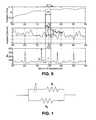
- FIG. 9A typical plot of the time varying impedance obtained by the present method is shown in FIG. 9 .
- FIG. 9the raw impedance data is plotted against time (measured by sample number) in the top graph.
- This graphincludes the impedance from all time varying impedance components in the thoracic cavity including variation in blood volume, blood cell orientation and changes due to respiration.
- the centre graph of FIG. 9depicts the rate of change of impedance attributable to cardiac function of a patient.
- the graphwas generated by removing the low frequency components from the top graph and obtaining the rate of change of impedance from the remaining data.
- the inner electrodescan also be used to record ECG vectors. In order to generate more ECG vectors more inner electrode combinations are required.
- the outer electrodescan also be used to record the ECG vectors.
- the processing unit, or the operator,can automatically or manually select the most appropriate ECG vector.
- An external ECG monitorcan also be connected or alternatively a separate module can be incorporated into the invention with additional electrodes to calculate the ECG vectors.
- the ECGcan advantageously be used to aid in the determination of cardiac events.
- An example ECG outputis depicted in the lower graph of FIG. 9 .
- fiducial pointsmust also be suitably identified.
- the ECG data and/or other suitable physiological measurement techniquesmay be employed to aid this process.
- Other physiological parametersthat could be used to assist in identifying fiducial points in the cardiac cycle include invasive/non-invasive blood pressure, pulse oximetry, peripheral bioimpedance measurements, ultrasound techniques and infrared/radio frequency spectroscopy. Such techniques can be used singularly or in a plurality to optimally determine cardiac event timing.
- an artificial neural network or weighted averages to determine the cardiac events as identified by conductance measurements combined with other methods of physiological measuresoffer an improved method of identifying these points.
- the start and end of left ventricular ejectionare indicated by the vertical lines on the graphs of FIG. 9 .
- the time between these pointsis the left ventricle ejection time (LVET).
- Measures of cardiac functioncan then be determined from this data. For example, the following method can be used to calculate blood velocity and stroke volume. The present example uses impedance measures to calculate cardiac output. However the same functions can be described using admittance or a combination of the two. The following formula can be used to calculate cardiac output:
- embodiments of the present inventioncan be applied to determine other measures of cardiac performance, including but not limited to, stroke volume, cardiac index, stroke index, systemic vascular resistance/index, acceleration, acceleration index, velocity, velocity index, thoracic fluid content, left ventricular ejection time, Pre-ejection period, systolic time ratio, left cardiac work/index, heart rate and mean arterial pressure.
- the characteristic frequencymay be determined during a cardiac cycle by applying an electrical signal having a plurality of frequencies (or multiple electrical signals at different frequencies), detecting electrical signals in response to the applied signals, processing the detected signals (e.g., to remove unwanted components such as ECGs and other signals), comparing the applied electrical signals at each frequency with the response signals at each frequency, and fitting the signals to a function from which the characteristic frequency may be determined.
- FIGS. 6A and 6Billustrate this.
- instantaneous impedance valuesare determined for each frequency f i at time t o 260 , and are fit to a function 270 (such as the Wessel plot shown in FIG. 8 ).
- the characteristic frequencymay be identified from the function.
- the characteristic frequency from the Wessel plotis the frequency at the top of the arch (e.g., the frequency with the largest reactance).
- the characteristic frequencymay be determined by approximating the maximum reactance over the applied frequency range.
- the signal(s) applied to the subjectmay be a signal (or signals) having a plurality of frequency components, or a series of signals at different frequencies.
- the response signalthat is measured from the subject after the application of one or more electrical signals arises because of the electrical properties of the body. This response is usually referred to as a response signal.
- the response signalmay also be referred to as an evoked response or evoked signal, and is typically a passive response.
- the responsedoes not usually include a regenerative evoked (e.g., active) response from electrically active tissue.
- this characteristic frequencymay provide a relatively accurate means of determining cardiac function by then applying an electrical signal at the characteristic frequency and receiving the response electrical signal at that frequency.
- This electrical stimulation and samplingmay be repeated during a complete or partial cardiac cycle.
- the stimulated and response signalsmay be compared (e.g., after filtering or other signal processing) to determine an instantaneous impedance or any components of the instantaneous impedance, such as resistance, reactance, phase and magnitude.
- the resistance and reactance, and the impedance and phaseare all mathematically related, and with any two you can calculate the other two. Further, as is known in the art, any of these components can be determined from the applied and response signals.
- R varis determined iteratively by calculating instantaneous impedance values at a plurality of frequencies at each time point.
- FIGS. 10 and 11describe an alternative method of determining a measure of cardiac function, by instead determining the characteristic frequency (stimulating at multiple frequencies) and using this characteristic frequency to determine the instantaneous impedance (or components of the instantaneous impedance).
- the step of determining a characteristic frequencymay be performed only once during a cardiac cycle, or only periodically during a cardiac cycle, rather than at each time point t i .
- FIG. 10is a schematic flowchart further illustrating one method of determining a measure of cardiac function in a subject.
- a characteristic frequency for the subject 1001is determined.
- the characteristic frequencymay be determined by applying an electrical signal (or signals) having a plurality of frequencies to the subject, receiving the response signal(s) from the subject, and determining an instantaneous impedance value (or a component of the impedance) at each of the plurality of frequencies, fitting the values to a function (e.g., a frequency dependent function), and determining the characteristic frequency using the function.
- a functione.g., a frequency dependent function
- any appropriate range of frequenciesmay be used, including frequencies between 2 and 10,000 kHz (e.g., 2-200 kHz, etc.), and any appropriate number of frequencies may be used (e.g., 2, 8, 16, 50, 100, etc.).
- the instantaneous impedance valuesmay be determined at each time point, in some variations components of the instantaneous impedance values (e.g., reactance and/or resistance) are determined at each time point, rather than the combined impedance value. In some variations, phase is used.
- the impedance, or a component of the impedancecan be determined at different time points during all or part of a cardiac cycle 1003 .
- the intra-cellular resistancemay be calculated from the impedance.
- the reactance component of the impedanceis determined at different time points of a cardiac cycle by applying electrical signals at the characteristic frequency.
- at least one reactance time pointmay be determined at that characteristic frequency.
- This reactance time pointmay be referred to as an instantaneous reactance at that time point.
- the component of impedance determined at each time point using the characteristic frequencyis phase, magnitude (or both).
- the instantaneous impedanceis determined using the characteristic frequency at each time point.
- the impedance (or a component of the impedance) at the characteristic frequencyis determined at discrete time points during a complete cardiac cycle 1005 . Any number of time points within the cardiac cycle may be taken (e.g., the number of sample points within the cardiac cycle). Although most of the methods described herein take measurements over a full cardiac cycle, a portion of a cardiac cycle or multiple cardiac cycles may also be used. As briefly mentioned above, these instantaneous values determined during the cardiac cycle using the characteristic frequency may be stored for use in determining a cardiac function such as stroke volume or cardiac output.
- a new characteristic frequencymay be determined during the cardiac cycle, as indicated by the dashed line 1011 in FIG. 10 .
- a new characteristic frequencymay be determined for each time point, or for some subset of time points.
- a measure of cardiac functionmay be determined using the instantaneous impedance (or a component of impedance) value(s) determined at the characteristic frequency 1007 in the previous steps.
- the instantaneous impedance values measured at the characteristic frequencymay be used to determine a stroke volume and/or cardiac output.
- the maximum change in impedance, (dz/dt) maxis proportional to the stroke volume and also to the cardiac output.
- stroke volumemay be represented as:
- SVL ′3 ⁇ ⁇ d z d t ⁇ max ⁇ V ⁇ ⁇ E ⁇ ⁇ T Z B
- SVstroke volume
- (dz/dt) maxmaximum rate of change in measured impedance at the beginning of systolic cycle
- VETleft ventricular ejection time
- L′thoracic length estimated from the subject's height and weight using a nomogram. L′ also accounts for blood resistivity.
- Z Bis a baseline impedance value.
- the constantsmay be combined, expressing the stroke volume in terms of elements (e.g., (dz/dt) max ) that may be determined for each cardiac cycle.
- the instantaneous reactance at the characteristic frequencymay be used to determine a measure of cardiac function.
- the instantaneous reactance at the characteristic frequencycan be measured at each sample point during a cardiac cycle by stimulating the subject at the characteristic frequency.
- the change in the reactance (dX/dt) maxis also proportional to the stroke volume and the cardiac output, and may therefore be used (in conjunction with appropriate nomograms) to determine these measures of cardiac function.
- FIG. 11illustrates this exemplary method.
- a system for analyzing cardiac function in a subjectmay include any of the elements described above, and may also include one or more processors for executing the procedures described herein.
- a systemmay include a processor (e.g., microprocessor) for controlling the application of an electrical signal having a plurality of frequencies to the subject 1101 .
- the processormay be connected to a signal generator and electrodes to be connected to the subject for stimulation.
- the controllermay also be connected to electrodes for receiving an electrical signal from the subject in response to the applied signal 1103 .
- the input signalmay also be sent to the controller, and both the input and output signals may be digitized, filtered, or otherwise conditioned.
- the processormay further determine a characteristic frequency by comparing the applied and received electrical signals 1105 , as described above.
- the characteristic frequencymay then be used to determine an instantaneous reactance, or any other appropriate characteristic of impedance, including phase 1107 .
- the systemmay detect the relative phase shift (d ⁇ /dt) between the injected signal and the response signal at discrete times during a full cardiac cycle or a portion of a cardiac cycle by applying an electrical signal at the determined characteristic frequency and comparing the phase of the response signal to the applied signal.
- the characteristic frequencymay be determined once during the cardiac cycle (e.g., at the start of the measurement), or a new characteristic frequency may be determined before determining the component of the impedance (e.g., reactance or phase shift) at each time point, as indicated by the dashed line 1117 in FIG. 11 .
- a new characteristic frequencymay be recalculated after some number of data point (or a fraction of the cardiac cycle).
- phase shiftmay be used to determine stroke volume and/or cardiac output.
- the phase shiftmay be proportional to the changes in blood flow in the aorta, as previously described.
- VETis ventricular ejection time
- C′is a constant that may be based on individual patient characteristics (including height, weight, gender, age, etc.).
- the VETmay be determined for each cardiac cycle.
- the ECGmay be used to determine the length of each heart beat, as well as the start of ejection and the end of ejection, from which VET can be estimated.
- Heart rate(and therefore cardiac output) may also be determined from the phase information.
- the measure of cardiac function determinedmay be displayed, stored or transmitted.
- any of the systems for analyzing cardiac function described hereinmay include a display (e.g., screen, printer, etc.) or telemetry (wireless, LAN, etc.), or the like.
- the systems described hereinmay also include one or more inputs such as keyboards, mouse, touch screen, etc. for inputting subject information.
Landscapes
- Health & Medical Sciences (AREA)
- Life Sciences & Earth Sciences (AREA)
- Cardiology (AREA)
- Medical Informatics (AREA)
- Surgery (AREA)
- Biophysics (AREA)
- Pathology (AREA)
- Engineering & Computer Science (AREA)
- Biomedical Technology (AREA)
- Heart & Thoracic Surgery (AREA)
- Veterinary Medicine (AREA)
- Molecular Biology (AREA)
- Physics & Mathematics (AREA)
- Animal Behavior & Ethology (AREA)
- General Health & Medical Sciences (AREA)
- Public Health (AREA)
- Hematology (AREA)
- Physiology (AREA)
- Radiology & Medical Imaging (AREA)
- Nuclear Medicine, Radiotherapy & Molecular Imaging (AREA)
- Measurement And Recording Of Electrical Phenomena And Electrical Characteristics Of The Living Body (AREA)
Abstract
Description
- direct current is conducted through the extracellular fluid only since the reactance of the cell membrane will be infinite;
- an applied alternating current is conducted through the extracellular and intracellular pathways in a ratio dependent on the frequency of the applied signal.
YCPE=(ωτ)m(Gωτ=1+jBωτ=1) (1)
where:
- CO denotes cardiac output (liters/min),
is as indicated on
- k1is an optional population specific correction factor based on one or more subject parameters, such as at least the height and weight, but can also include distance between the electrodes and age;
- c1is an optional calibration coefficient used to convert the units from Ohmic units to liters (which may be uniquely defined at manufacture for each monitoring device used to implement the method),
- Z0is an optional baseline Impedance measured at the characteristic frequency (between 10 Ohms and 150 Ohms),
- TRRis the interval between two R waves obtained from the ECG (found from the ECG or impedance or conductance data),
- TLVEis left ventricular ejection time (measured from either the conductance or impedance curve or preferably a combination of other physiological measurement techniques) and
- n (range −4>n<4) and m (range −4>m<4) are optional constants.
where: SV=stroke volume, (dz/dt)max=maximum rate of change in measured impedance at the beginning of systolic cycle, VET=left ventricular ejection time, and L′=thoracic length estimated from the subject's height and weight using a nomogram. L′ also accounts for blood resistivity. ZBis a baseline impedance value. Thus, the constants may be combined, expressing the stroke volume in terms of elements (e.g., (dz/dt)max) that may be determined for each cardiac cycle. Cardiac output is related to stroke volume (e.g., cardiac output=SV*heart rate).
SV=C′*(dφ/dt)max*VET
where VET is ventricular ejection time, and C′ is a constant that may be based on individual patient characteristics (including height, weight, gender, age, etc.). As previously described, the VET may be determined for each cardiac cycle. For example, the ECG may be used to determine the length of each heart beat, as well as the start of ejection and the end of ejection, from which VET can be estimated. Heart rate (and therefore cardiac output) may also be determined from the phase information.
Claims (20)
Priority Applications (1)
| Application Number | Priority Date | Filing Date | Title |
|---|---|---|---|
| US13/305,606US8509886B2 (en) | 2004-06-21 | 2011-11-28 | Cardiac monitoring system |
Applications Claiming Priority (10)
| Application Number | Priority Date | Filing Date | Title |
|---|---|---|---|
| AU2004903334 | 2004-06-21 | ||
| AUAU2004903334 | 2004-06-21 | ||
| AU2004903334AAU2004903334A0 (en) | 2004-06-21 | High resolution bio-impedance method | |
| AUAU2004906181 | 2004-10-26 | ||
| AU2004906181AAU2004906181A0 (en) | 2004-10-26 | Improved method for measurement of biological parameters | |
| AU2004906181 | 2004-10-26 | ||
| PCT/AU2005/000893WO2005122881A1 (en) | 2004-06-21 | 2005-06-21 | Cardiac monitoring system |
| US11/776,456US8068906B2 (en) | 2004-06-21 | 2007-07-11 | Cardiac monitoring system |
| US62980408A | 2008-11-11 | 2008-11-11 | |
| US13/305,606US8509886B2 (en) | 2004-06-21 | 2011-11-28 | Cardiac monitoring system |
Related Parent Applications (1)
| Application Number | Title | Priority Date | Filing Date |
|---|---|---|---|
| US11/776,456ContinuationUS8068906B2 (en) | 2004-06-21 | 2007-07-11 | Cardiac monitoring system |
Publications (2)
| Publication Number | Publication Date |
|---|---|
| US20120071772A1 US20120071772A1 (en) | 2012-03-22 |
| US8509886B2true US8509886B2 (en) | 2013-08-13 |
Family
ID=39877896
Family Applications (2)
| Application Number | Title | Priority Date | Filing Date |
|---|---|---|---|
| US11/776,456Active2027-06-02US8068906B2 (en) | 2004-06-21 | 2007-07-11 | Cardiac monitoring system |
| US13/305,606Expired - Fee RelatedUS8509886B2 (en) | 2004-06-21 | 2011-11-28 | Cardiac monitoring system |
Family Applications Before (1)
| Application Number | Title | Priority Date | Filing Date |
|---|---|---|---|
| US11/776,456Active2027-06-02US8068906B2 (en) | 2004-06-21 | 2007-07-11 | Cardiac monitoring system |
Country Status (7)
| Country | Link |
|---|---|
| US (2) | US8068906B2 (en) |
| EP (1) | EP2178434B1 (en) |
| JP (1) | JP2010533040A (en) |
| AU (1) | AU2008275068B2 (en) |
| CA (1) | CA2692795C (en) |
| ES (1) | ES2616335T3 (en) |
| WO (1) | WO2009009616A1 (en) |
Families Citing this family (53)
| Publication number | Priority date | Publication date | Assignee | Title |
|---|---|---|---|---|
| AUPQ113799A0 (en) | 1999-06-22 | 1999-07-15 | University Of Queensland, The | A method and device for measuring lymphoedema |
| US8744564B2 (en) | 2004-06-18 | 2014-06-03 | Impedimed Limited | Oedema detection |
| US8068906B2 (en)* | 2004-06-21 | 2011-11-29 | Aorora Technologies Pty Ltd | Cardiac monitoring system |
| US20090030332A1 (en)* | 2005-01-26 | 2009-01-29 | Schecter Stuart O | microfabricated cardiac sensor with tactile feedback and method and apparatus for calibrating the same using a plurality of signals |
| US20100312129A1 (en) | 2005-01-26 | 2010-12-09 | Schecter Stuart O | Cardiovascular haptic handle system |
| US20060167529A1 (en) | 2005-01-26 | 2006-07-27 | Schecter Stuart O | Method and algorithm for defining the pathologic state from a plurality of intrinsically and extrinsically derived signals |
| US7918787B2 (en)* | 2005-02-02 | 2011-04-05 | Voyage Medical, Inc. | Tissue visualization and manipulation systems |
| US20110054343A1 (en) | 2005-07-01 | 2011-03-03 | Impedimed Limited | Monitoring system |
| EP2460468A1 (en) | 2005-07-01 | 2012-06-06 | Impedimed Limited | Monitoring system |
| WO2007014417A1 (en) | 2005-08-02 | 2007-02-08 | Impedimed Limited | Impedance parameter values |
| JP5208749B2 (en) | 2005-10-11 | 2013-06-12 | インペダイムド・リミテッド | Hydration status monitoring |
| US7794404B1 (en)* | 2006-03-31 | 2010-09-14 | Pacesetter, Inc | System and method for estimating cardiac pressure using parameters derived from impedance signals detected by an implantable medical device |
| US8600497B1 (en) | 2006-03-31 | 2013-12-03 | Pacesetter, Inc. | Systems and methods to monitor and treat heart failure conditions |
| AU2007266311B2 (en) | 2006-05-30 | 2014-01-30 | Impedimed Limited | Impedance measurements |
| AU2007327573B2 (en) | 2006-11-30 | 2013-07-18 | Impedimed Limited | Measurement apparatus |
| CA2675438A1 (en)* | 2007-01-15 | 2008-07-24 | Impedimed Limited | Monitoring system |
| US11617518B2 (en)* | 2007-03-05 | 2023-04-04 | Wisys Technology Foundation, Inc. | Method for detecting both pre-cancerous and cancerous tissues |
| CA2703361C (en) | 2007-03-30 | 2016-06-28 | Impedimed Limited | Active guarding for reduction of resistive and capacitive signal loading with adjustable control of compensation level |
| US8504153B2 (en) | 2007-04-04 | 2013-08-06 | Pacesetter, Inc. | System and method for estimating cardiac pressure based on cardiac electrical conduction delays using an implantable medical device |
| US8208999B2 (en) | 2007-04-04 | 2012-06-26 | Pacesetter, Inc. | System and method for estimating electrical conduction delays from immittance values measured using an implantable medical device |
| WO2008128281A1 (en) | 2007-04-20 | 2008-10-30 | Impedimed Limited | Monitoring system and probe |
| US20110046505A1 (en) | 2007-08-09 | 2011-02-24 | Impedimed Limited | Impedance measurement process |
| AU2008324750B2 (en)* | 2007-11-05 | 2014-01-16 | Impedimed Limited | Impedance determination |
| EP2249696B1 (en)* | 2008-02-14 | 2017-06-07 | N.I. MEDICAL Ltd. | Method and system for use in monitoring left ventricular dysfunction |
| AU2008207672B2 (en)* | 2008-02-15 | 2013-10-31 | Impedimed Limited | Impedance Analysis |
| DK2346395T3 (en)* | 2008-09-22 | 2018-06-06 | Cheetah Medical Inc | SYSTEM AND PROCEDURE FOR DETERMINING BLOOD FLOW |
| US9615766B2 (en) | 2008-11-28 | 2017-04-11 | Impedimed Limited | Impedance measurement process |
| US10699206B2 (en)* | 2009-04-22 | 2020-06-30 | Rodrigo E. Teixeira | Iterative probabilistic parameter estimation apparatus and method of use therefor |
| AT508114B1 (en)* | 2009-09-03 | 2010-11-15 | Heller Arnulf Dipl Ing | DEVICE FOR NON-INVASIVE DETERMINATION OF ARTERIAL BLOOD PRESSURE |
| US9615767B2 (en) | 2009-10-26 | 2017-04-11 | Impedimed Limited | Fluid level indicator determination |
| CA2778770A1 (en) | 2009-11-18 | 2011-05-26 | Chung Shing Fan | Signal distribution for patient-electrode measurements |
| US9351654B2 (en) | 2010-06-08 | 2016-05-31 | Alivecor, Inc. | Two electrode apparatus and methods for twelve lead ECG |
| US8700137B2 (en) | 2012-08-30 | 2014-04-15 | Alivecor, Inc. | Cardiac performance monitoring system for use with mobile communications devices |
| US8509882B2 (en) | 2010-06-08 | 2013-08-13 | Alivecor, Inc. | Heart monitoring system usable with a smartphone or computer |
| US8942828B1 (en) | 2011-04-13 | 2015-01-27 | Stuart Schecter, LLC | Minimally invasive cardiovascular support system with true haptic coupling |
| EP2790576A4 (en) | 2011-12-14 | 2015-07-08 | Intersection Medical Inc | Devices, systems and methods for determining the relative spatial change in subsurface resistivities across frequencies in tissue |
| US20140121564A1 (en)* | 2012-05-03 | 2014-05-01 | Aliphcom | Estimating body fat in a user |
| US10013082B2 (en) | 2012-06-05 | 2018-07-03 | Stuart Schecter, LLC | Operating system with haptic interface for minimally invasive, hand-held surgical instrument |
| US8731649B2 (en)* | 2012-08-30 | 2014-05-20 | Covidien Lp | Systems and methods for analyzing changes in cardiac output |
| US9254095B2 (en) | 2012-11-08 | 2016-02-09 | Alivecor | Electrocardiogram signal detection |
| WO2014107700A1 (en) | 2013-01-07 | 2014-07-10 | Alivecor, Inc. | Methods and systems for electrode placement |
| US20170325711A1 (en)* | 2013-01-29 | 2017-11-16 | Seca Ag | Method and apparatus for testing plausibility of measurement values in body composition analysis |
| WO2014145927A1 (en) | 2013-03-15 | 2014-09-18 | Alivecor, Inc. | Systems and methods for processing and analyzing medical data |
| US9247911B2 (en) | 2013-07-10 | 2016-02-02 | Alivecor, Inc. | Devices and methods for real-time denoising of electrocardiograms |
| EP4537748A1 (en) | 2013-12-12 | 2025-04-16 | Alivecor, Inc. | Methods and systems for arrhythmia tracking and scoring |
| ES2820923T3 (en) | 2015-05-13 | 2021-04-22 | Alivecor Inc | Mismatch monitoring |
| WO2017100188A2 (en)* | 2015-12-07 | 2017-06-15 | Medici Technologies, LLC | Methods and apparatuses for assessment and management of hemodynamic status |
| JP6709462B2 (en)* | 2016-06-10 | 2020-06-17 | 公益財団法人ヒューマンサイエンス振興財団 | Behavior physical fitness evaluation device, operation method of behavior physical fitness evaluation device, and program |
| TWI598073B (en)* | 2016-12-15 | 2017-09-11 | 財團法人工業技術研究院 | Physiological signal measurement method and physiological signal measurement device |
| KR102042898B1 (en)* | 2017-10-31 | 2019-11-27 | 한국 한의학 연구원 | Apparatus and method of obtaining the health information using multi-frequency bio-impedance measurement |
| US12114918B2 (en) | 2019-08-15 | 2024-10-15 | Biosense Webster (Israel) Ltd. | Dynamic ablation and sensing according to contact of segmented electrodes |
| KR102305179B1 (en)* | 2019-10-16 | 2021-09-27 | 주식회사 바이랩 | Method and apparatus for monitoring of cardiopulmonary parameters using electrical impedance tomography |
| US11197634B2 (en)* | 2020-04-28 | 2021-12-14 | Wayne C. A. Wright | Geospatial bioimpedance biosurveillance tool |
Citations (142)
| Publication number | Priority date | Publication date | Assignee | Title |
|---|---|---|---|---|
| US3316896A (en) | 1962-10-18 | 1967-05-02 | Thomasset Auguste Louis | Apparatus and methods for the measure of the electrical impedance of living organisms |
| US3851641A (en) | 1973-11-29 | 1974-12-03 | J Toole | Method and apparatus for determining internal impedance of animal body part |
| USRE30101E (en) | 1964-08-19 | 1979-09-25 | Regents Of The University Of Minnesota | Impedance plethysmograph |
| US4450527A (en) | 1982-06-29 | 1984-05-22 | Bomed Medical Mfg. Ltd. | Noninvasive continuous cardiac output monitor |
| US4486835A (en) | 1981-05-13 | 1984-12-04 | Yeda Research And Development Co. Ltd. | Apparatus and techniques for electric tomography |
| US4695955A (en) | 1983-12-26 | 1987-09-22 | A2F | Electronic device providing a universal interface between sensors and an acquisition and processing unit of the signals originating from said sensors |
| US4890630A (en) | 1989-01-23 | 1990-01-02 | Cherne Medical, Inc. | Bio-electric noise cancellation system |
| US4905705A (en) | 1989-03-03 | 1990-03-06 | Research Triangle Institute | Impedance cardiometer |
| US4924875A (en) | 1987-10-09 | 1990-05-15 | Biometrak Corporation | Cardiac biopotential analysis system and method |
| US5063937A (en) | 1990-09-12 | 1991-11-12 | Wright State University | Multiple frequency bio-impedance measurement system |
| US5086781A (en) | 1989-11-14 | 1992-02-11 | Bookspan Mark A | Bioelectric apparatus for monitoring body fluid compartments |
| US5101828A (en) | 1991-04-11 | 1992-04-07 | Rutgers, The State University Of Nj | Methods and apparatus for nonivasive monitoring of dynamic cardiac performance |
| WO1993018821A1 (en) | 1992-03-26 | 1993-09-30 | Medtronic, Inc. | Multiple frequency impedance measurement for physiological monitoring of the condition of a patient's body tissue |
| US5280429A (en) | 1991-04-30 | 1994-01-18 | Xitron Technologies | Method and apparatus for displaying multi-frequency bio-impedance |
| WO1994001040A1 (en) | 1992-07-13 | 1994-01-20 | Hertford Medical Limited | Heart monitoring apparatus |
| EP0581073A2 (en) | 1992-07-09 | 1994-02-02 | Spacelabs Medical, Inc. | Application specific integrated circuit for physiological monitoring |
| US5309917A (en) | 1991-09-12 | 1994-05-10 | Drexel University | System and method of impedance cardiography and heartbeat determination |
| WO1994010922A1 (en) | 1992-11-13 | 1994-05-26 | Ep Technologies, Inc. | Cardial ablation systems using temperature monitoring |
| US5423326A (en) | 1991-09-12 | 1995-06-13 | Drexel University | Apparatus and method for measuring cardiac output |
| US5449000A (en) | 1988-05-24 | 1995-09-12 | Abc Development | System for body impedance data acquisition utilizing segmental impedance & multiple frequency impedance |
| US5454377A (en) | 1993-10-08 | 1995-10-03 | The Ohio State University | Method for measuring the myocardial electrical impedance spectrum |
| US5469859A (en) | 1992-06-24 | 1995-11-28 | N.I. Medical Ltd. | Non-invasive method and device for collecting measurements representing body activity and determining cardiorespiratory parameters of the human body based upon the measurements collected |
| WO1996001586A1 (en) | 1994-07-07 | 1996-01-25 | Reining International Ltd. | Impedance cardiograph apparatus and method |
| US5503157A (en) | 1995-03-17 | 1996-04-02 | Sramek; Bohumir | System for detection of electrical bioimpedance signals |
| US5526808A (en) | 1990-10-04 | 1996-06-18 | Microcor, Inc. | Method and apparatus for noninvasively determining hematocrit |
| EP0339471B1 (en) | 1988-04-25 | 1997-03-26 | Lifecor, Inc. (Pennsylvania Corporation) | Portable device for sensing cardiac function and automatically delivering electrical therapy |
| WO1997011638A2 (en) | 1995-09-26 | 1997-04-03 | A.J. Van Liebergen Holding B.V. | Apparatus for the in-vivo non-invasive measurement of a biological parameter concerning a bodily fluid of a person or animal |
| US5626146A (en) | 1992-12-18 | 1997-05-06 | British Technology Group Limited | Electrical impedance tomography |
| FR2748928A1 (en) | 1996-05-23 | 1997-11-28 | Jabourian Artin Pascal | Portable electronic cardiac rhythm detector |
| WO1998006328A1 (en) | 1996-08-09 | 1998-02-19 | R.S. Medical Monitoring Ltd. | Method and device for stable impedance plethysmography |
| US5732710A (en) | 1996-08-09 | 1998-03-31 | R.S. Medical Monitoring Ltd. | Method and device for stable impedance plethysmography |
| US5735284A (en) | 1992-06-24 | 1998-04-07 | N.I. Medical Ltd. | Method and system for non-invasive determination of the main cardiorespiratory parameters of the human body |
| US5746214A (en) | 1992-10-30 | 1998-05-05 | British Technology Group Limited | Investigation of a body |
| CN1180513A (en) | 1996-10-23 | 1998-05-06 | 黄莹 | Cardiac function recording transmitter |
| US5759159A (en) | 1996-09-25 | 1998-06-02 | Ormco Corporation | Method and apparatus for apical detection with complex impedance measurement |
| RU2112416C1 (en) | 1994-05-10 | 1998-06-10 | Научно-исследовательский институт вычислительной техники | Method for checking of tissue or organ condition after operation and device for its realization |
| US5788643A (en) | 1997-04-22 | 1998-08-04 | Zymed Medical Instrumentation, Inc. | Process for monitoring patients with chronic congestive heart failure |
| WO1998033553A1 (en) | 1997-01-31 | 1998-08-06 | Medtronic, Inc. | Impedance respiratory rate measuring edema monitor |
| US5807272A (en) | 1995-10-31 | 1998-09-15 | Worcester Polytechnic Institute | Impedance spectroscopy system for ischemia monitoring and detection |
| EP0865763A2 (en) | 1997-03-06 | 1998-09-23 | Nte, S.A. | Apparatus for measuring volumes and global and segmental corporal composition in human beings |
| WO1998051211A1 (en) | 1997-05-14 | 1998-11-19 | Silem, Heiki | Apparatuses and methods for a noninvasive measurement of physiological parameters |
| US5906614A (en) | 1991-11-08 | 1999-05-25 | Ep Technologies, Inc. | Tissue heating and ablation systems and methods using predicted temperature for monitoring and control |
| RU2138193C1 (en) | 1996-06-26 | 1999-09-27 | Государственное предприятие конструкторское бюро "СПЕЦВУЗАВТОМАТИКА" | Method of separation of electrical component of cardiac activity |
| US5957861A (en) | 1997-01-31 | 1999-09-28 | Medtronic, Inc. | Impedance monitor for discerning edema through evaluation of respiratory rate |
| CN1236597A (en) | 1999-03-16 | 1999-12-01 | 秦大明 | Automatic analysis system for remote-measuring dynamic cardiac function and method for measuring dynamic cardiac kinetic energy. |
| US6018677A (en) | 1997-11-25 | 2000-01-25 | Tectrix Fitness Equipment, Inc. | Heart rate monitor and method |
| WO2000019886A1 (en) | 1997-03-20 | 2000-04-13 | Polartechnics Limited | Tissue diagnostic system |
| JP2000107138A (en) | 1998-10-01 | 2000-04-18 | Denso Corp | Health management apparatus |
| JP2000139867A (en) | 1998-11-10 | 2000-05-23 | Sekisui Chem Co Ltd | Body composition estimation method, body composition estimation apparatus and recording medium recording body composition estimation program |
| WO2000040955A1 (en) | 1999-01-05 | 2000-07-13 | Kaiku Limited | Impedance measurements of bodily matter |
| US6125297A (en) | 1998-02-06 | 2000-09-26 | The United States Of America As Represented By The United States National Aeronautics And Space Administration | Body fluids monitor |
| US6142949A (en) | 1998-11-24 | 2000-11-07 | Ortivus Ab | Lead protection and identification system |
| WO2000079255A1 (en) | 1999-06-22 | 2000-12-28 | The University Of Queensland | A method and device for measuring tissue oedema |
| JP2001037735A (en) | 1999-07-27 | 2001-02-13 | Matsushita Electric Ind Co Ltd | Bioimpedance measurement device |
| EP1078597A2 (en) | 1996-04-08 | 2001-02-28 | Rheo-Graphic PTE LTD | Non-invasive monitoring of hemodynamic parameters using thoracic bioimpedance and electrocardiographic measurements |
| JP2001061804A (en) | 1999-08-26 | 2001-03-13 | Tanita Corp | Bioimpedance measurement device |
| US6208890B1 (en) | 1998-03-03 | 2001-03-27 | Seb, S.A. | Device and method for measuring the composition of the body |
| WO2001027605A1 (en) | 1999-10-12 | 2001-04-19 | Gerald Wiegand | Highly time resolved impedance spectroscopy |
| EP1112715A1 (en) | 1999-12-28 | 2001-07-04 | Tanita Corporation | Apparatus for determining degree of restoration of diseased part |
| US20010051774A1 (en) | 2000-02-28 | 2001-12-13 | Peter Littrup | Multidimensional bioelectrical tissue analyzer |
| CN1329875A (en) | 2000-06-30 | 2002-01-09 | 株式会社百利达 | Equipment for measuring bio-impedance |
| JP2002502274A (en) | 1997-04-15 | 2002-01-22 | パラスパイナル ダイアグノスティック コーポレイション | Computerized electromyographic diagnosis system |
| EP1238630A2 (en) | 2001-03-01 | 2002-09-11 | Tre Esse Progettazione Biomedica S.r.l | Process and implantable device for the intrapulmonary assessing of density dependant physical properties of the lung tissue |
| US20020138019A1 (en) | 1997-10-03 | 2002-09-26 | Alvin Wexler | High definition electrical impedance tomography |
| EP1247487A1 (en) | 2001-04-03 | 2002-10-09 | Osypka Medical GmbH | Apparatus and method for determining an approximate value of the stroke volume and the cardiac output of the heart |
| US6469732B1 (en) | 1998-11-06 | 2002-10-22 | Vtel Corporation | Acoustic source location using a microphone array |
| US6472888B2 (en) | 2000-01-31 | 2002-10-29 | Tanita Corporation | Bioelectrical impedance measuring apparatus constructed by one-chip integrated circuit |
| US20030004403A1 (en) | 2001-06-29 | 2003-01-02 | Darrel Drinan | Gateway platform for biological monitoring and delivery of therapeutic compounds |
| US6512949B1 (en) | 1999-07-12 | 2003-01-28 | Medtronic, Inc. | Implantable medical device for measuring time varying physiologic conditions especially edema and for responding thereto |
| US20030023184A1 (en) | 2001-07-23 | 2003-01-30 | Jonathan Pitts-Crick | Method and system for diagnosing and administering therapy of pulmonary congestion |
| US20030028221A1 (en) | 2001-07-31 | 2003-02-06 | Qingsheng Zhu | Cardiac rhythm management system for edema |
| US6532384B1 (en) | 1999-09-03 | 2003-03-11 | Tanita Corporation | Bioelectrical impedence measuring method and body composition measuring apparatus |
| US6551252B2 (en) | 2000-04-17 | 2003-04-22 | Vivometrics, Inc. | Systems and methods for ambulatory monitoring of physiological signs |
| US6560480B1 (en) | 1994-10-24 | 2003-05-06 | Transscan Medical Ltd. | Localization of anomalies in tissue and guidance of invasive tools based on impedance imaging |
| US6561986B2 (en) | 2001-01-17 | 2003-05-13 | Cardiodynamics International Corporation | Method and apparatus for hemodynamic assessment including fiducial point detection |
| US20030105411A1 (en) | 2000-03-03 | 2003-06-05 | Smallwood Rodney Harris | Electrical impedance measuring method for differentiating tissue types |
| US20030120170A1 (en) | 2000-08-14 | 2003-06-26 | Fansan Zhu | Device and method for monitoring and controlling physiologic parameters of a dialysis patient using segmental bioimpedance |
| US20030120182A1 (en) | 2000-04-20 | 2003-06-26 | Pulmosonix Pty Ltd | Method and apparatus for determining conditions of biological tissues |
| NL1019789C2 (en) | 2002-01-18 | 2003-07-21 | A J Van Liebergen Holding B V | Connector and electrode combination, especially for measurements on human body, has additional signal carrier connectable to responder |
| EP1329190A1 (en) | 2002-12-14 | 2003-07-23 | Research Institute of Tsinghua University in Shenzhen | Apparatus and method for monitoring body composition by measuring body dielectric constant and body impedance based on digital frequency sampling |
| US6602201B1 (en) | 2000-07-10 | 2003-08-05 | Cardiodynamics International Corporation | Apparatus and method for determining cardiac output in a living subject |
| US6615077B1 (en) | 2000-08-14 | 2003-09-02 | Renal Research Institute, Llc | Device and method for monitoring and controlling physiologic parameters of a dialysis patient using segmental bioimpedence |
| US6631292B1 (en) | 2001-03-23 | 2003-10-07 | Rjl Systems, Inc. | Bio-electrical impedance analyzer |
| US6636754B1 (en) | 2000-07-10 | 2003-10-21 | Cardiodynamics International Corporation | Apparatus and method for determining cardiac output in a living subject |
| US6643543B2 (en) | 2000-08-01 | 2003-11-04 | Tanita Corporation | Body water amount condition judging apparatus by multi-frequency bioelectric impedance measurement |
| US20030216664A1 (en) | 2000-06-09 | 2003-11-20 | Suarez Fernando Sipmann | Method and apparatus for displaying information obtained by electrical impedance tomography data |
| US20040015095A1 (en) | 2002-07-16 | 2004-01-22 | Jianhua Li | Method and device for measuring signals for electrical impedance tomography by using correlation techinique |
| US20040019292A1 (en) | 2002-07-29 | 2004-01-29 | Drinan Darrel Dean | Method and apparatus for bioelectric impedance based identification of subjects |
| US6714813B2 (en) | 2000-01-21 | 2004-03-30 | Tanita Corporation | Method for measuring the degree of edema and apparatus using the same |
| US20040073130A1 (en) | 1998-12-10 | 2004-04-15 | Stephan Bohm | Method and apparatus for determining alveolar opening and closing |
| WO2004030535A1 (en) | 2002-10-07 | 2004-04-15 | Cnsystems Medizintechnik Gmbh | Impedance-based measuring method for hemodynamic parameters |
| US20040073127A1 (en) | 2001-07-17 | 2004-04-15 | Gmp Companies, Inc. | Wireless ECG system |
| US6725089B2 (en) | 1999-10-12 | 2004-04-20 | Tanita Corporation | Living body measuring apparatus |
| WO2004032738A1 (en) | 2002-10-09 | 2004-04-22 | Queensland University Of Technology | High resolution bio-impedance device |
| WO2004047638A1 (en) | 2002-11-25 | 2004-06-10 | Regents Of The University Of Minnesota | Impedance monitoring for detecting pulmonary edema and thoracic congestion |
| US20040116819A1 (en) | 2001-10-01 | 2004-06-17 | Eckhard Alt | Congestive heart failure monitor and ventilation measuring implant |
| US20040158167A1 (en) | 2002-11-27 | 2004-08-12 | Smith Kenneth Carless | Apparatus and method for performing impedance measurements |
| US20040167423A1 (en) | 2002-12-20 | 2004-08-26 | Luana Pillon | RXc graph and RXc Z-score graph methods |
| US6790178B1 (en) | 1999-09-24 | 2004-09-14 | Healthetech, Inc. | Physiological monitor and associated computation, display and communication unit |
| WO2004084087A1 (en) | 2003-03-22 | 2004-09-30 | Qinetiq Limited | Monitoring electrical muscular activity |
| US6807443B2 (en) | 2001-05-01 | 2004-10-19 | Cheetah Medical Inc. | High-resolution medical monitoring apparatus particularly useful for electrocardiographs |
| US20040236202A1 (en) | 2003-05-22 | 2004-11-25 | Burton Steven Angell | Expandable strap for use in electrical impedance tomography |
| US20040234113A1 (en) | 2003-02-24 | 2004-11-25 | Vanderbilt University | Elastography imaging modalities for characterizing properties of tissue |
| US20040242989A1 (en) | 2003-03-25 | 2004-12-02 | Fansan Zhu | Device and method for performing electrical impedance tomography |
| US6829501B2 (en) | 2001-12-20 | 2004-12-07 | Ge Medical Systems Information Technologies, Inc. | Patient monitor and method with non-invasive cardiac output monitoring |
| US6829503B2 (en) | 2001-10-01 | 2004-12-07 | Scicotec Gmbh | Congestive heart failure monitor |
| US20040260167A1 (en) | 2003-04-08 | 2004-12-23 | Steffen Leonhardt | Electrode belt |
| US20050039763A1 (en) | 2001-12-12 | 2005-02-24 | Matthias Kraemer | Determining the hydration status of a patient |
| WO2005018432A2 (en) | 2003-08-20 | 2005-03-03 | Philometron, Inc. | Hydration monitoring |
| US20050080460A1 (en) | 2003-10-14 | 2005-04-14 | Li Wang | Method and apparatus for monitoring tissue fluid content for use in an implantable cardiac device |
| US20050101875A1 (en) | 2001-10-04 | 2005-05-12 | Right Corporation | Non-invasive body composition monitor, system and method |
| US20050107719A1 (en) | 2002-07-03 | 2005-05-19 | Tel-Aviv University Future Technology Development L.P. | Apparatus for monitoring CHF patients using bio-impedance technique |
| JP2005137683A (en) | 2003-11-07 | 2005-06-02 | Tanita Corp | Shielded cable and bioelectrical impedance value or biological composition information acquisition device using shielded cable |
| US20050177062A1 (en) | 2002-10-07 | 2005-08-11 | Cnsystems Medizintechnik Gmbh | Impedance-based measuring method for hemodynamic parameters |
| US20050192488A1 (en) | 2004-02-12 | 2005-09-01 | Biopeak Corporation | Non-invasive method and apparatus for determining a physiological parameter |
| US20050203435A1 (en) | 2004-03-15 | 2005-09-15 | Tanita Corporation | Skin condition estimating apparatus |
| US20050201598A1 (en) | 2004-02-09 | 2005-09-15 | Francois Harel | Computation of a geometric parameter of a cardiac chamber from a cardiac tomography data set |
| US20050215918A1 (en) | 2004-03-24 | 2005-09-29 | Frantz Ann K | Thoracic impedance monitor and electrode array and method of use |
| US20050228309A1 (en) | 2002-12-31 | 2005-10-13 | Fisher John S | Sealant Plug Delivery Methods |
| US20050261743A1 (en) | 2004-05-19 | 2005-11-24 | Kroll Mark W | System and method for automated fluid monitoring |
| US20050283091A1 (en) | 2004-06-18 | 2005-12-22 | Tallinn University Of Technology | Method and apparatus for determining conditions of a biological tissue |
| US6980852B2 (en) | 2002-01-25 | 2005-12-27 | Subqiview Inc. | Film barrier dressing for intravascular tissue monitoring system |
| WO2005122888A1 (en) | 2004-06-18 | 2005-12-29 | The University Of Queensland | Oedema detection |
| US20060004300A1 (en) | 2002-11-22 | 2006-01-05 | James Kennedy | Multifrequency bioimpedance determination |
| US20060064029A1 (en) | 2002-07-03 | 2006-03-23 | Tel-Aviv University Future Technology Development L.P. | Bio-impedance apparatus and method |
| US20060122540A1 (en) | 2000-08-14 | 2006-06-08 | Fansan Zhu | Device and method for the determination of dry weight by continuous measurement of resistance and calculation of circumference in a body segment using segmental bioimpedance analysis |
| US20060200033A1 (en) | 2003-05-12 | 2006-09-07 | Cheetah Medical Inc. C/O Pepper Hamiton | System, method and apparatus for measuring blood flow and blood volume |
| US7122012B2 (en) | 2001-07-26 | 2006-10-17 | Medrad, Inc. | Detection of fluids in tissue |
| US20060241719A1 (en) | 2000-09-13 | 2006-10-26 | Foster George B | Electrical stimulation of tissue for therapeutic and diagnostic purposes |
| US20060264775A1 (en) | 2003-03-14 | 2006-11-23 | Mills Gary N | Methods of and apparatus for determining fluid volume presence in mammalian tissue |
| US7149573B2 (en) | 2003-04-25 | 2006-12-12 | Medtronic, Inc. | Method and apparatus for impedance signal localizations from implanted devices |
| US20070027402A1 (en) | 2003-09-12 | 2007-02-01 | Renal Reserach Institute, Llc | Bioimpedance methods and apparatus |
| US7184821B2 (en) | 2003-12-03 | 2007-02-27 | Regents Of The University Of Minnesota | Monitoring thoracic fluid changes |
| US7186220B2 (en) | 2003-07-02 | 2007-03-06 | Cardiac Pacemakers, Inc. | Implantable devices and methods using frequency-domain analysis of thoracic signal |
| US7233823B2 (en) | 2001-10-12 | 2007-06-19 | Seb S.A. | Apparatus for measuring body composition |
| US7251524B1 (en) | 2000-07-10 | 2007-07-31 | Cardiodynamics International Corporation | Apparatus and method for determining cardiac output in a living subject |
| US20080064981A1 (en) | 2002-11-07 | 2008-03-13 | Christopher Gregory | Method and apparatus for determining electrical properties of objects containing inhomogeneities |
| US20080287823A1 (en) | 2005-07-20 | 2008-11-20 | Scott Matthew Chetham | Index Determination |
| US20090043222A1 (en) | 2005-10-11 | 2009-02-12 | Scott Chetham | Hydration status monitoring |
| US20090082679A1 (en) | 2004-06-21 | 2009-03-26 | Impedance Cardiology Systems, Inc. | Cardiac monitoring system |
| US20090143663A1 (en) | 2005-07-01 | 2009-06-04 | Impedance Cardiology Systems Inc. | Pulmonary Monitoring System |
| US8068906B2 (en)* | 2004-06-21 | 2011-11-29 | Aorora Technologies Pty Ltd | Cardiac monitoring system |
Family Cites Families (15)
| Publication number | Priority date | Publication date | Assignee | Title |
|---|---|---|---|---|
| US7387610B2 (en)* | 2004-08-19 | 2008-06-17 | Cardiac Pacemakers, Inc. | Thoracic impedance detection with blood resistivity compensation |
| US7865236B2 (en)* | 2004-10-20 | 2011-01-04 | Nervonix, Inc. | Active electrode, bio-impedance based, tissue discrimination system and methods of use |
| DE102004059082A1 (en)* | 2004-12-02 | 2006-06-08 | Biotronik Crm Patent Ag | Device for determining the thorax impedance |
| US7701227B2 (en)* | 2005-01-05 | 2010-04-20 | Rensselaer Polytechnic Institute | High precision voltage source for electrical impedance tomography |
| US20060224079A1 (en)* | 2005-03-31 | 2006-10-05 | Washchuk Bohdan O | Edema monitoring system and method utilizing an implantable medical device |
| US7603170B2 (en)* | 2005-04-26 | 2009-10-13 | Cardiac Pacemakers, Inc. | Calibration of impedance monitoring of respiratory volumes using thoracic D.C. impedance |
| US7907997B2 (en)* | 2005-05-11 | 2011-03-15 | Cardiac Pacemakers, Inc. | Enhancements to the detection of pulmonary edema when using transthoracic impedance |
| US9089275B2 (en)* | 2005-05-11 | 2015-07-28 | Cardiac Pacemakers, Inc. | Sensitivity and specificity of pulmonary edema detection when using transthoracic impedance |
| US7340296B2 (en)* | 2005-05-18 | 2008-03-04 | Cardiac Pacemakers, Inc. | Detection of pleural effusion using transthoracic impedance |
| DE102005031752B4 (en)* | 2005-07-07 | 2017-11-02 | Drägerwerk AG & Co. KGaA | Electroimpedance tomography device with common-mode signal suppression |
| US7205782B2 (en)* | 2005-07-11 | 2007-04-17 | Brigham Young University | Scanned impedance imaging system method and apparatus |
| DE102005041385B4 (en)* | 2005-09-01 | 2018-10-04 | Drägerwerk AG & Co. KGaA | Device for protecting an electrical impedance tomograph against overvoltage pulses |
| JP5124881B2 (en)* | 2005-12-20 | 2013-01-23 | アウトポイエジ・パルテイシパソエス・リミタダ | Electrode assembly for electrical impedance tomography |
| US8442627B2 (en)* | 2005-12-30 | 2013-05-14 | Medtronic, Inc. | Advanced thoracic fluid monitoring capability with impedance |
| KR100700112B1 (en)* | 2006-02-03 | 2007-03-28 | 경희대학교 산학협력단 | Electrical Impedance Tomography Method and System |
- 2007
- 2007-07-11USUS11/776,456patent/US8068906B2/enactiveActive
- 2008
- 2008-07-09AUAU2008275068Apatent/AU2008275068B2/ennot_activeCeased
- 2008-07-09EPEP08796130.6Apatent/EP2178434B1/ennot_activeNot-in-force
- 2008-07-09JPJP2010516230Apatent/JP2010533040A/enactivePending
- 2008-07-09CACA2692795Apatent/CA2692795C/ennot_activeExpired - Fee Related
- 2008-07-09ESES08796130.6Tpatent/ES2616335T3/enactiveActive
- 2008-07-09WOPCT/US2008/069559patent/WO2009009616A1/enactiveApplication Filing
- 2011
- 2011-11-28USUS13/305,606patent/US8509886B2/ennot_activeExpired - Fee Related
Patent Citations (159)
| Publication number | Priority date | Publication date | Assignee | Title |
|---|---|---|---|---|
| US3316896A (en) | 1962-10-18 | 1967-05-02 | Thomasset Auguste Louis | Apparatus and methods for the measure of the electrical impedance of living organisms |
| USRE30101E (en) | 1964-08-19 | 1979-09-25 | Regents Of The University Of Minnesota | Impedance plethysmograph |
| US3851641A (en) | 1973-11-29 | 1974-12-03 | J Toole | Method and apparatus for determining internal impedance of animal body part |
| US4486835A (en) | 1981-05-13 | 1984-12-04 | Yeda Research And Development Co. Ltd. | Apparatus and techniques for electric tomography |
| US4450527A (en) | 1982-06-29 | 1984-05-22 | Bomed Medical Mfg. Ltd. | Noninvasive continuous cardiac output monitor |
| US4695955A (en) | 1983-12-26 | 1987-09-22 | A2F | Electronic device providing a universal interface between sensors and an acquisition and processing unit of the signals originating from said sensors |
| US4924875A (en) | 1987-10-09 | 1990-05-15 | Biometrak Corporation | Cardiac biopotential analysis system and method |
| EP0339471B1 (en) | 1988-04-25 | 1997-03-26 | Lifecor, Inc. (Pennsylvania Corporation) | Portable device for sensing cardiac function and automatically delivering electrical therapy |
| US5449000A (en) | 1988-05-24 | 1995-09-12 | Abc Development | System for body impedance data acquisition utilizing segmental impedance & multiple frequency impedance |
| US4890630A (en) | 1989-01-23 | 1990-01-02 | Cherne Medical, Inc. | Bio-electric noise cancellation system |
| US4905705A (en) | 1989-03-03 | 1990-03-06 | Research Triangle Institute | Impedance cardiometer |
| US5086781A (en) | 1989-11-14 | 1992-02-11 | Bookspan Mark A | Bioelectric apparatus for monitoring body fluid compartments |
| US5063937A (en) | 1990-09-12 | 1991-11-12 | Wright State University | Multiple frequency bio-impedance measurement system |
| US5526808A (en) | 1990-10-04 | 1996-06-18 | Microcor, Inc. | Method and apparatus for noninvasively determining hematocrit |
| US5101828A (en) | 1991-04-11 | 1992-04-07 | Rutgers, The State University Of Nj | Methods and apparatus for nonivasive monitoring of dynamic cardiac performance |
| US5280429A (en) | 1991-04-30 | 1994-01-18 | Xitron Technologies | Method and apparatus for displaying multi-frequency bio-impedance |
| US5423326A (en) | 1991-09-12 | 1995-06-13 | Drexel University | Apparatus and method for measuring cardiac output |
| US5309917A (en) | 1991-09-12 | 1994-05-10 | Drexel University | System and method of impedance cardiography and heartbeat determination |
| US5906614A (en) | 1991-11-08 | 1999-05-25 | Ep Technologies, Inc. | Tissue heating and ablation systems and methods using predicted temperature for monitoring and control |
| WO1993018821A1 (en) | 1992-03-26 | 1993-09-30 | Medtronic, Inc. | Multiple frequency impedance measurement for physiological monitoring of the condition of a patient's body tissue |
| US5469859A (en) | 1992-06-24 | 1995-11-28 | N.I. Medical Ltd. | Non-invasive method and device for collecting measurements representing body activity and determining cardiorespiratory parameters of the human body based upon the measurements collected |
| US5735284A (en) | 1992-06-24 | 1998-04-07 | N.I. Medical Ltd. | Method and system for non-invasive determination of the main cardiorespiratory parameters of the human body |
| EP0581073A2 (en) | 1992-07-09 | 1994-02-02 | Spacelabs Medical, Inc. | Application specific integrated circuit for physiological monitoring |
| WO1994001040A1 (en) | 1992-07-13 | 1994-01-20 | Hertford Medical Limited | Heart monitoring apparatus |
| US5746214A (en) | 1992-10-30 | 1998-05-05 | British Technology Group Limited | Investigation of a body |
| WO1994010922A1 (en) | 1992-11-13 | 1994-05-26 | Ep Technologies, Inc. | Cardial ablation systems using temperature monitoring |
| US5626146A (en) | 1992-12-18 | 1997-05-06 | British Technology Group Limited | Electrical impedance tomography |
| US5454377A (en) | 1993-10-08 | 1995-10-03 | The Ohio State University | Method for measuring the myocardial electrical impedance spectrum |
| RU2112416C1 (en) | 1994-05-10 | 1998-06-10 | Научно-исследовательский институт вычислительной техники | Method for checking of tissue or organ condition after operation and device for its realization |
| WO1996001586A1 (en) | 1994-07-07 | 1996-01-25 | Reining International Ltd. | Impedance cardiograph apparatus and method |
| US6560480B1 (en) | 1994-10-24 | 2003-05-06 | Transscan Medical Ltd. | Localization of anomalies in tissue and guidance of invasive tools based on impedance imaging |
| US5503157A (en) | 1995-03-17 | 1996-04-02 | Sramek; Bohumir | System for detection of electrical bioimpedance signals |
| US5529072A (en) | 1995-03-17 | 1996-06-25 | Sramek; Bohumir | System for detection of electrical bioimpedance signals |
| US6339722B1 (en) | 1995-09-26 | 2002-01-15 | A. J. Van Liebergen Holding B.V. | Apparatus for the in-vivo non-invasive measurement of a biological parameter concerning a bodily fluid of a person or animal |
| WO1997011638A2 (en) | 1995-09-26 | 1997-04-03 | A.J. Van Liebergen Holding B.V. | Apparatus for the in-vivo non-invasive measurement of a biological parameter concerning a bodily fluid of a person or animal |
| US5807272A (en) | 1995-10-31 | 1998-09-15 | Worcester Polytechnic Institute | Impedance spectroscopy system for ischemia monitoring and detection |
| EP1078597A2 (en) | 1996-04-08 | 2001-02-28 | Rheo-Graphic PTE LTD | Non-invasive monitoring of hemodynamic parameters using thoracic bioimpedance and electrocardiographic measurements |
| FR2748928A1 (en) | 1996-05-23 | 1997-11-28 | Jabourian Artin Pascal | Portable electronic cardiac rhythm detector |
| RU2138193C1 (en) | 1996-06-26 | 1999-09-27 | Государственное предприятие конструкторское бюро "СПЕЦВУЗАВТОМАТИКА" | Method of separation of electrical component of cardiac activity |
| US5732710A (en) | 1996-08-09 | 1998-03-31 | R.S. Medical Monitoring Ltd. | Method and device for stable impedance plethysmography |
| WO1998006328A1 (en) | 1996-08-09 | 1998-02-19 | R.S. Medical Monitoring Ltd. | Method and device for stable impedance plethysmography |
| US5759159A (en) | 1996-09-25 | 1998-06-02 | Ormco Corporation | Method and apparatus for apical detection with complex impedance measurement |
| CN1180513A (en) | 1996-10-23 | 1998-05-06 | 黄莹 | Cardiac function recording transmitter |
| WO1998033553A1 (en) | 1997-01-31 | 1998-08-06 | Medtronic, Inc. | Impedance respiratory rate measuring edema monitor |
| US5876353A (en) | 1997-01-31 | 1999-03-02 | Medtronic, Inc. | Impedance monitor for discerning edema through evaluation of respiratory rate |
| US5957861A (en) | 1997-01-31 | 1999-09-28 | Medtronic, Inc. | Impedance monitor for discerning edema through evaluation of respiratory rate |
| US6151523A (en) | 1997-03-06 | 2000-11-21 | Nte S.A. | Apparatus and procedure for measuring volumes and global and segmental corporal composition in human beings |
| EP0865763A2 (en) | 1997-03-06 | 1998-09-23 | Nte, S.A. | Apparatus for measuring volumes and global and segmental corporal composition in human beings |
| WO2000019886A1 (en) | 1997-03-20 | 2000-04-13 | Polartechnics Limited | Tissue diagnostic system |
| JP2002502274A (en) | 1997-04-15 | 2002-01-22 | パラスパイナル ダイアグノスティック コーポレイション | Computerized electromyographic diagnosis system |
| US5788643A (en) | 1997-04-22 | 1998-08-04 | Zymed Medical Instrumentation, Inc. | Process for monitoring patients with chronic congestive heart failure |
| WO1998051211A1 (en) | 1997-05-14 | 1998-11-19 | Silem, Heiki | Apparatuses and methods for a noninvasive measurement of physiological parameters |
| US20020138019A1 (en) | 1997-10-03 | 2002-09-26 | Alvin Wexler | High definition electrical impedance tomography |
| US6018677A (en) | 1997-11-25 | 2000-01-25 | Tectrix Fitness Equipment, Inc. | Heart rate monitor and method |
| US6125297A (en) | 1998-02-06 | 2000-09-26 | The United States Of America As Represented By The United States National Aeronautics And Space Administration | Body fluids monitor |
| US6208890B1 (en) | 1998-03-03 | 2001-03-27 | Seb, S.A. | Device and method for measuring the composition of the body |
| JP2000107138A (en) | 1998-10-01 | 2000-04-18 | Denso Corp | Health management apparatus |
| US6469732B1 (en) | 1998-11-06 | 2002-10-22 | Vtel Corporation | Acoustic source location using a microphone array |
| JP2000139867A (en) | 1998-11-10 | 2000-05-23 | Sekisui Chem Co Ltd | Body composition estimation method, body composition estimation apparatus and recording medium recording body composition estimation program |
| US6142949A (en) | 1998-11-24 | 2000-11-07 | Ortivus Ab | Lead protection and identification system |
| US20040073130A1 (en) | 1998-12-10 | 2004-04-15 | Stephan Bohm | Method and apparatus for determining alveolar opening and closing |
| WO2000040955A1 (en) | 1999-01-05 | 2000-07-13 | Kaiku Limited | Impedance measurements of bodily matter |
| CN1236597A (en) | 1999-03-16 | 1999-12-01 | 秦大明 | Automatic analysis system for remote-measuring dynamic cardiac function and method for measuring dynamic cardiac kinetic energy. |
| US6760617B2 (en) | 1999-06-22 | 2004-07-06 | The University Of Queensland | Method and device for measuring tissue oedema |
| WO2000079255A1 (en) | 1999-06-22 | 2000-12-28 | The University Of Queensland | A method and device for measuring tissue oedema |
| US6512949B1 (en) | 1999-07-12 | 2003-01-28 | Medtronic, Inc. | Implantable medical device for measuring time varying physiologic conditions especially edema and for responding thereto |
| JP2001037735A (en) | 1999-07-27 | 2001-02-13 | Matsushita Electric Ind Co Ltd | Bioimpedance measurement device |
| US6724200B2 (en) | 1999-08-26 | 2004-04-20 | Tanita Corporation | Apparatus for measuring the bioelectrical impedance of a living body |
| JP2001061804A (en) | 1999-08-26 | 2001-03-13 | Tanita Corp | Bioimpedance measurement device |
| EP1080686B1 (en) | 1999-09-03 | 2004-03-31 | Tanita Corporation | Bioelectrical impedance measuring method and body composition measuring apparatus |
| US6532384B1 (en) | 1999-09-03 | 2003-03-11 | Tanita Corporation | Bioelectrical impedence measuring method and body composition measuring apparatus |
| US6790178B1 (en) | 1999-09-24 | 2004-09-14 | Healthetech, Inc. | Physiological monitor and associated computation, display and communication unit |
| US6556001B1 (en) | 1999-10-12 | 2003-04-29 | Gerald Wiegand | Highly time resolved impedance spectroscopy |
| WO2001027605A1 (en) | 1999-10-12 | 2001-04-19 | Gerald Wiegand | Highly time resolved impedance spectroscopy |
| US6725089B2 (en) | 1999-10-12 | 2004-04-20 | Tanita Corporation | Living body measuring apparatus |
| US20030173976A1 (en) | 1999-10-12 | 2003-09-18 | Gerald Wiegand | Highly time resolved impedance spectroscopy |
| EP1112715A1 (en) | 1999-12-28 | 2001-07-04 | Tanita Corporation | Apparatus for determining degree of restoration of diseased part |
| US6496725B2 (en) | 1999-12-28 | 2002-12-17 | Tanita Corporation | Apparatus for determining degree of restoration of diseased part |
| US6714813B2 (en) | 2000-01-21 | 2004-03-30 | Tanita Corporation | Method for measuring the degree of edema and apparatus using the same |
| US6472888B2 (en) | 2000-01-31 | 2002-10-29 | Tanita Corporation | Bioelectrical impedance measuring apparatus constructed by one-chip integrated circuit |
| US20010051774A1 (en) | 2000-02-28 | 2001-12-13 | Peter Littrup | Multidimensional bioelectrical tissue analyzer |
| US20030105411A1 (en) | 2000-03-03 | 2003-06-05 | Smallwood Rodney Harris | Electrical impedance measuring method for differentiating tissue types |
| US6551252B2 (en) | 2000-04-17 | 2003-04-22 | Vivometrics, Inc. | Systems and methods for ambulatory monitoring of physiological signs |
| US20030120182A1 (en) | 2000-04-20 | 2003-06-26 | Pulmosonix Pty Ltd | Method and apparatus for determining conditions of biological tissues |
| US20030216664A1 (en) | 2000-06-09 | 2003-11-20 | Suarez Fernando Sipmann | Method and apparatus for displaying information obtained by electrical impedance tomography data |
| CN1329875A (en) | 2000-06-30 | 2002-01-09 | 株式会社百利达 | Equipment for measuring bio-impedance |
| US6636754B1 (en) | 2000-07-10 | 2003-10-21 | Cardiodynamics International Corporation | Apparatus and method for determining cardiac output in a living subject |
| US7251524B1 (en) | 2000-07-10 | 2007-07-31 | Cardiodynamics International Corporation | Apparatus and method for determining cardiac output in a living subject |
| US6602201B1 (en) | 2000-07-10 | 2003-08-05 | Cardiodynamics International Corporation | Apparatus and method for determining cardiac output in a living subject |
| US6643543B2 (en) | 2000-08-01 | 2003-11-04 | Tanita Corporation | Body water amount condition judging apparatus by multi-frequency bioelectric impedance measurement |
| US20030120170A1 (en) | 2000-08-14 | 2003-06-26 | Fansan Zhu | Device and method for monitoring and controlling physiologic parameters of a dialysis patient using segmental bioimpedance |
| US6615077B1 (en) | 2000-08-14 | 2003-09-02 | Renal Research Institute, Llc | Device and method for monitoring and controlling physiologic parameters of a dialysis patient using segmental bioimpedence |
| US20060122540A1 (en) | 2000-08-14 | 2006-06-08 | Fansan Zhu | Device and method for the determination of dry weight by continuous measurement of resistance and calculation of circumference in a body segment using segmental bioimpedance analysis |
| US20060241719A1 (en) | 2000-09-13 | 2006-10-26 | Foster George B | Electrical stimulation of tissue for therapeutic and diagnostic purposes |
| US6561986B2 (en) | 2001-01-17 | 2003-05-13 | Cardiodynamics International Corporation | Method and apparatus for hemodynamic assessment including fiducial point detection |
| EP1238630A2 (en) | 2001-03-01 | 2002-09-11 | Tre Esse Progettazione Biomedica S.r.l | Process and implantable device for the intrapulmonary assessing of density dependant physical properties of the lung tissue |
| US6631292B1 (en) | 2001-03-23 | 2003-10-07 | Rjl Systems, Inc. | Bio-electrical impedance analyzer |
| EP1247487A1 (en) | 2001-04-03 | 2002-10-09 | Osypka Medical GmbH | Apparatus and method for determining an approximate value of the stroke volume and the cardiac output of the heart |
| US6511438B2 (en) | 2001-04-03 | 2003-01-28 | Osypka Medical Gmbh | Apparatus and method for determining an approximation of the stroke volume and the cardiac output of the heart |
| US6807443B2 (en) | 2001-05-01 | 2004-10-19 | Cheetah Medical Inc. | High-resolution medical monitoring apparatus particularly useful for electrocardiographs |
| US20030004403A1 (en) | 2001-06-29 | 2003-01-02 | Darrel Drinan | Gateway platform for biological monitoring and delivery of therapeutic compounds |
| US20040073127A1 (en) | 2001-07-17 | 2004-04-15 | Gmp Companies, Inc. | Wireless ECG system |
| US20030023184A1 (en) | 2001-07-23 | 2003-01-30 | Jonathan Pitts-Crick | Method and system for diagnosing and administering therapy of pulmonary congestion |
| US7122012B2 (en) | 2001-07-26 | 2006-10-17 | Medrad, Inc. | Detection of fluids in tissue |
| US20030028221A1 (en) | 2001-07-31 | 2003-02-06 | Qingsheng Zhu | Cardiac rhythm management system for edema |
| US20040116819A1 (en) | 2001-10-01 | 2004-06-17 | Eckhard Alt | Congestive heart failure monitor and ventilation measuring implant |
| US6829503B2 (en) | 2001-10-01 | 2004-12-07 | Scicotec Gmbh | Congestive heart failure monitor |
| US20050101875A1 (en) | 2001-10-04 | 2005-05-12 | Right Corporation | Non-invasive body composition monitor, system and method |
| US7233823B2 (en) | 2001-10-12 | 2007-06-19 | Seb S.A. | Apparatus for measuring body composition |
| US20050039763A1 (en) | 2001-12-12 | 2005-02-24 | Matthias Kraemer | Determining the hydration status of a patient |
| US6829501B2 (en) | 2001-12-20 | 2004-12-07 | Ge Medical Systems Information Technologies, Inc. | Patient monitor and method with non-invasive cardiac output monitoring |
| NL1019789C2 (en) | 2002-01-18 | 2003-07-21 | A J Van Liebergen Holding B V | Connector and electrode combination, especially for measurements on human body, has additional signal carrier connectable to responder |
| US7184820B2 (en) | 2002-01-25 | 2007-02-27 | Subqiview, Inc. | Tissue monitoring system for intravascular infusion |
| US6980852B2 (en) | 2002-01-25 | 2005-12-27 | Subqiview Inc. | Film barrier dressing for intravascular tissue monitoring system |
| US7169107B2 (en) | 2002-01-25 | 2007-01-30 | Karen Jersey-Willuhn | Conductivity reconstruction based on inverse finite element measurements in a tissue monitoring system |
| US20060064029A1 (en) | 2002-07-03 | 2006-03-23 | Tel-Aviv University Future Technology Development L.P. | Bio-impedance apparatus and method |
| US7096061B2 (en) | 2002-07-03 | 2006-08-22 | Tel-Aviv University Future Technology Development L.P. | Apparatus for monitoring CHF patients using bio-impedance technique |
| US20050107719A1 (en) | 2002-07-03 | 2005-05-19 | Tel-Aviv University Future Technology Development L.P. | Apparatus for monitoring CHF patients using bio-impedance technique |
| US20040015095A1 (en) | 2002-07-16 | 2004-01-22 | Jianhua Li | Method and device for measuring signals for electrical impedance tomography by using correlation techinique |
| US20040019292A1 (en) | 2002-07-29 | 2004-01-29 | Drinan Darrel Dean | Method and apparatus for bioelectric impedance based identification of subjects |
| US20050177062A1 (en) | 2002-10-07 | 2005-08-11 | Cnsystems Medizintechnik Gmbh | Impedance-based measuring method for hemodynamic parameters |
| WO2004030535A1 (en) | 2002-10-07 | 2004-04-15 | Cnsystems Medizintechnik Gmbh | Impedance-based measuring method for hemodynamic parameters |
| WO2004032738A1 (en) | 2002-10-09 | 2004-04-22 | Queensland University Of Technology | High resolution bio-impedance device |
| US20060247543A1 (en) | 2002-10-09 | 2006-11-02 | Bruce Cornish | High resoution bio-impedance device |
| US20080064981A1 (en) | 2002-11-07 | 2008-03-13 | Christopher Gregory | Method and apparatus for determining electrical properties of objects containing inhomogeneities |
| US20060004300A1 (en) | 2002-11-22 | 2006-01-05 | James Kennedy | Multifrequency bioimpedance determination |
| WO2004047638A1 (en) | 2002-11-25 | 2004-06-10 | Regents Of The University Of Minnesota | Impedance monitoring for detecting pulmonary edema and thoracic congestion |
| US20040158167A1 (en) | 2002-11-27 | 2004-08-12 | Smith Kenneth Carless | Apparatus and method for performing impedance measurements |
| EP1329190A1 (en) | 2002-12-14 | 2003-07-23 | Research Institute of Tsinghua University in Shenzhen | Apparatus and method for monitoring body composition by measuring body dielectric constant and body impedance based on digital frequency sampling |
| US20040167423A1 (en) | 2002-12-20 | 2004-08-26 | Luana Pillon | RXc graph and RXc Z-score graph methods |
| US20050228309A1 (en) | 2002-12-31 | 2005-10-13 | Fisher John S | Sealant Plug Delivery Methods |
| US20040234113A1 (en) | 2003-02-24 | 2004-11-25 | Vanderbilt University | Elastography imaging modalities for characterizing properties of tissue |
| US20060264775A1 (en) | 2003-03-14 | 2006-11-23 | Mills Gary N | Methods of and apparatus for determining fluid volume presence in mammalian tissue |
| WO2004084087A1 (en) | 2003-03-22 | 2004-09-30 | Qinetiq Limited | Monitoring electrical muscular activity |
| US20040242989A1 (en) | 2003-03-25 | 2004-12-02 | Fansan Zhu | Device and method for performing electrical impedance tomography |
| US20040260167A1 (en) | 2003-04-08 | 2004-12-23 | Steffen Leonhardt | Electrode belt |
| US7149573B2 (en) | 2003-04-25 | 2006-12-12 | Medtronic, Inc. | Method and apparatus for impedance signal localizations from implanted devices |
| US20060200033A1 (en) | 2003-05-12 | 2006-09-07 | Cheetah Medical Inc. C/O Pepper Hamiton | System, method and apparatus for measuring blood flow and blood volume |
| US20040236202A1 (en) | 2003-05-22 | 2004-11-25 | Burton Steven Angell | Expandable strap for use in electrical impedance tomography |
| US7186220B2 (en) | 2003-07-02 | 2007-03-06 | Cardiac Pacemakers, Inc. | Implantable devices and methods using frequency-domain analysis of thoracic signal |
| US20050070778A1 (en) | 2003-08-20 | 2005-03-31 | Lackey Robert P. | Hydration monitoring |
| WO2005018432A2 (en) | 2003-08-20 | 2005-03-03 | Philometron, Inc. | Hydration monitoring |
| US20070027402A1 (en) | 2003-09-12 | 2007-02-01 | Renal Reserach Institute, Llc | Bioimpedance methods and apparatus |
| US20050080460A1 (en) | 2003-10-14 | 2005-04-14 | Li Wang | Method and apparatus for monitoring tissue fluid content for use in an implantable cardiac device |
| JP2005137683A (en) | 2003-11-07 | 2005-06-02 | Tanita Corp | Shielded cable and bioelectrical impedance value or biological composition information acquisition device using shielded cable |
| US7184821B2 (en) | 2003-12-03 | 2007-02-27 | Regents Of The University Of Minnesota | Monitoring thoracic fluid changes |
| US20050201598A1 (en) | 2004-02-09 | 2005-09-15 | Francois Harel | Computation of a geometric parameter of a cardiac chamber from a cardiac tomography data set |
| US20050192488A1 (en) | 2004-02-12 | 2005-09-01 | Biopeak Corporation | Non-invasive method and apparatus for determining a physiological parameter |
| US20050203435A1 (en) | 2004-03-15 | 2005-09-15 | Tanita Corporation | Skin condition estimating apparatus |
| US20050215918A1 (en) | 2004-03-24 | 2005-09-29 | Frantz Ann K | Thoracic impedance monitor and electrode array and method of use |
| US20050261743A1 (en) | 2004-05-19 | 2005-11-24 | Kroll Mark W | System and method for automated fluid monitoring |
| WO2005122888A1 (en) | 2004-06-18 | 2005-12-29 | The University Of Queensland | Oedema detection |
| US20050283091A1 (en) | 2004-06-18 | 2005-12-22 | Tallinn University Of Technology | Method and apparatus for determining conditions of a biological tissue |
| US20080319336A1 (en) | 2004-06-18 | 2008-12-25 | Leigh Ward | Oedema Detection |
| US20090082679A1 (en) | 2004-06-21 | 2009-03-26 | Impedance Cardiology Systems, Inc. | Cardiac monitoring system |
| US8068906B2 (en)* | 2004-06-21 | 2011-11-29 | Aorora Technologies Pty Ltd | Cardiac monitoring system |
| US20090143663A1 (en) | 2005-07-01 | 2009-06-04 | Impedance Cardiology Systems Inc. | Pulmonary Monitoring System |
| US20080287823A1 (en) | 2005-07-20 | 2008-11-20 | Scott Matthew Chetham | Index Determination |
| US20090043222A1 (en) | 2005-10-11 | 2009-02-12 | Scott Chetham | Hydration status monitoring |
Non-Patent Citations (11)
| Title |
|---|
| Bella et al., "Relations of left ventrical mass to fat-free and adipose body mass: the strong heart study," Circulation, vol. 98, pp. 2538-2544, Dec. 8, 1998. |
| Bernstein; "A new stroke volume equation for thoracic electrical bio impedance," Critical Care Medicine; Oct. 1986; vol. 14; pp. 904-909. |
| Ellis, K.J. et al., "Human hydrometry: comparison of multifrequency bioelectrical impedance with 2H2O and bromine dilution," Journal of Applied Physiology, vol. 85, No. 3, pp. 1056-1062, Sep. 1998. |
| Iacobellis et al., "Influence of excess fat on cardiac morphology and function: study in uncomplicated obesity," Obesity Research, vol. 10, No. 8, pp. 767-773, Aug. 8, 2002. |
| Jones, C.H. et al., "Extracellular fluid volume determined by bioelectric impedance and serum albumin in CAPD Patients," Nephrology Dialysis Transplantation, vol. 13, pp. 393-397, Feb. 1998. |
| Karason et al., "Impact of blood pressure and insulin on the relationship between body fat and left ventricular structure," European Heart Journal, vol. 24, pp. 1500-1505, May 2003. |
| McAdams et al.; Tissue impedance: a historical overview; Physiological Measurement, Institute of Physics Publishing, Bristol, GB; 16 (3A); pp. A1-A13; Aug. 1, 1995. |
| Thomas, B.J., "Future Technologies," Asia Pacific Journal Clinical Nutrition, vol. 4, No. 1, pp. 157-159, Mar. 1995. |
| Thomas, et al.; "Bioimpedance spectrometer in the determination of body water compartments: Accuracy and clinical significance;" Appl. Radiation. Isotopes; vol. 49, No. 5/6; pp. 447-455; Jun. 1998. |
| Woodrow, G. et al., "Effects of icodextrin in automated peritoneal dialysis on blood pressure and bioelectrical impedance analysis," Nephrology Dialysis Transplantation, vol. 15, pp. 862-866, Jun. 2000. |
| Yoshinaga et al., "Effect of total adipose weight and systemic hypertension on left ventrical mass in children," American Journal of Cardiology, vol. 76, pp. 785-787, Oct. 15, 1995. |
Also Published As
| Publication number | Publication date |
|---|---|
| US20120071772A1 (en) | 2012-03-22 |
| AU2008275068B2 (en) | 2012-07-05 |
| US8068906B2 (en) | 2011-11-29 |
| CA2692795C (en) | 2017-01-10 |
| EP2178434A1 (en) | 2010-04-28 |
| EP2178434B1 (en) | 2016-11-30 |
| AU2008275068A1 (en) | 2009-01-15 |
| CA2692795A1 (en) | 2009-01-15 |
| ES2616335T3 (en) | 2017-06-12 |
| WO2009009616A1 (en) | 2009-01-15 |
| JP2010533040A (en) | 2010-10-21 |
| US20080009759A1 (en) | 2008-01-10 |
Similar Documents
| Publication | Publication Date | Title |
|---|---|---|
| US8509886B2 (en) | Cardiac monitoring system | |
| US20090082679A1 (en) | Cardiac monitoring system | |
| CN104244814B (en) | The monitoring of cardiac output | |
| CN101522096B (en) | Method and system for non-invasive measurement of cardiac parameters | |
| EP1247487B1 (en) | Apparatus and method for determining an approximate value of the stroke volume and the cardiac output of the heart | |
| JP3844779B2 (en) | Method and apparatus for noninvasively measuring hematocrit | |
| US7096061B2 (en) | Apparatus for monitoring CHF patients using bio-impedance technique | |
| CN102551699B (en) | The system that non-invasive cardiac output is determined | |
| US20060247543A1 (en) | High resoution bio-impedance device | |
| US11832928B2 (en) | Heart failure indicator | |
| Sopic et al. | Touch-based system for beat-to-beat impedance cardiogram acquisition and hemodynamic parameters estimation | |
| Hu et al. | Noninvasive ambulatory hemodynamic monitoring based on electrocardiogram and impedance cardiography | |
| Corciova et al. | Hemodynamic monitoring using peripheral impedance plethysmography | |
| CORCIOVǍ et al. | Measuring system of hemodynamic parameters using electrical impedance |
Legal Events
| Date | Code | Title | Description |
|---|---|---|---|
| AS | Assignment | Owner name:AORORA TECHNOLOGIES PTY LTD, AUSTRALIA Free format text:ASSIGNMENT OF ASSIGNORS INTEREST;ASSIGNOR:CHETHAM, SCOTT MATTHEW;REEL/FRAME:028008/0197 Effective date:20080624 | |
| STCF | Information on status: patent grant | Free format text:PATENTED CASE | |
| AS | Assignment | Owner name:INTERSECTION MEDICAL, INC., CALIFORNIA Free format text:ASSIGNMENT OF ASSIGNORS INTEREST;ASSIGNOR:AORORA TECHNOLOGIES PTY LTD;REEL/FRAME:032302/0414 Effective date:20140129 | |
| AS | Assignment | Owner name:IMPEDIMED LIMITED, AUSTRALIA Free format text:ASSIGNMENT OF ASSIGNORS INTEREST;ASSIGNOR:INTERSECTION MEDICAL, INC.;REEL/FRAME:037625/0664 Effective date:20151023 | |
| FPAY | Fee payment | Year of fee payment:4 | |
| MAFP | Maintenance fee payment | Free format text:PAYMENT OF MAINTENANCE FEE, 8TH YR, SMALL ENTITY (ORIGINAL EVENT CODE: M2552); ENTITY STATUS OF PATENT OWNER: SMALL ENTITY Year of fee payment:8 | |
| FEPP | Fee payment procedure | Free format text:MAINTENANCE FEE REMINDER MAILED (ORIGINAL EVENT CODE: REM.); ENTITY STATUS OF PATENT OWNER: SMALL ENTITY | |
| LAPS | Lapse for failure to pay maintenance fees | Free format text:PATENT EXPIRED FOR FAILURE TO PAY MAINTENANCE FEES (ORIGINAL EVENT CODE: EXP.); ENTITY STATUS OF PATENT OWNER: SMALL ENTITY | |
| STCH | Information on status: patent discontinuation | Free format text:PATENT EXPIRED DUE TO NONPAYMENT OF MAINTENANCE FEES UNDER 37 CFR 1.362 | |
| FP | Lapsed due to failure to pay maintenance fee | Effective date:20250813 |