US8509215B2 - Delay management for distributed communications networks - Google Patents
Delay management for distributed communications networksDownload PDFInfo
- Publication number
- US8509215B2 US8509215B2US13/019,571US201113019571AUS8509215B2US 8509215 B2US8509215 B2US 8509215B2US 201113019571 AUS201113019571 AUS 201113019571AUS 8509215 B2US8509215 B2US 8509215B2
- Authority
- US
- United States
- Prior art keywords
- node
- delay
- delay value
- signal path
- adjacent
- Prior art date
- Legal status (The legal status is an assumption and is not a legal conclusion. Google has not performed a legal analysis and makes no representation as to the accuracy of the status listed.)
- Active
Links
Images


Classifications
- H—ELECTRICITY
- H04—ELECTRIC COMMUNICATION TECHNIQUE
- H04J—MULTIPLEX COMMUNICATION
- H04J3/00—Time-division multiplex systems
- H04J3/02—Details
- H04J3/06—Synchronising arrangements
- H04J3/0635—Clock or time synchronisation in a network
- H04J3/0682—Clock or time synchronisation in a network by delay compensation, e.g. by compensation of propagation delay or variations thereof, by ranging
- H—ELECTRICITY
- H04—ELECTRIC COMMUNICATION TECHNIQUE
- H04W—WIRELESS COMMUNICATION NETWORKS
- H04W24/00—Supervisory, monitoring or testing arrangements
- H—ELECTRICITY
- H04—ELECTRIC COMMUNICATION TECHNIQUE
- H04W—WIRELESS COMMUNICATION NETWORKS
- H04W28/00—Network traffic management; Network resource management
- H04W28/16—Central resource management; Negotiation of resources or communication parameters, e.g. negotiating bandwidth or QoS [Quality of Service]
- H04W28/18—Negotiating wireless communication parameters
- H—ELECTRICITY
- H04—ELECTRIC COMMUNICATION TECHNIQUE
- H04W—WIRELESS COMMUNICATION NETWORKS
- H04W48/00—Access restriction; Network selection; Access point selection
- H04W48/08—Access restriction or access information delivery, e.g. discovery data delivery
Definitions
- Distributed antenna systemsare widely used to seamlessly extend coverage for wireless communication signals to locations that are not adequately served by conventional base stations or to distribute capacity from centralized radio suites.
- These systemstypically include a host unit and a plurality of remote units.
- the host unitis typically coupled between a base station or radio suite and the plurality of remote units in one of many possible network configurations, e.g., hub and spoke, daisy-chain, or branch-and-tree.
- Each of the plurality of remote unitsincludes one or more antennas that send and receive wireless signals on behalf of the base station or radio suites.
- Each remote unitis typically located at a different distance from the host unit.
- a delay valueis typically set at each remote unit.
- conventional techniques used to establish the delay for the various remote unitshave added significant complexity and/or cost to the distributed antenna system.
- some common network synchronization techniquesinvolve the use of various locating technologies (e.g., global positioning systems, or GPS) that add further complexities and cost to operating these distributed antenna systems reliably and efficiently.
- a method for managing delay between nodes in a network having a plurality of nodes coupled together by a plurality of linkscomprises discovering a transport delay value for each of the plurality of links.
- the methodAt a first one of the plurality of nodes, the method generates a signal path delay value for each of the plurality of nodes coupled to the first one of the plurality of nodes using the discovered transport delay value associated with a link of the plurality of links that couples that node to the first one of the plurality of nodes and passes the generated signal path delay values over the links to the nodes of the plurality of nodes coupled to the first one of the plurality of nodes.
- the methodstores a received signal path delay value for the additional node to enable management of the delay for the additional node, generates a signal path delay value for each adjacent node of the plurality of nodes coupled to the additional node using the received signal path delay value and the discovered transport delay value for the link between the additional node and the adjacent node, and passes the generated signal path delay values over the additional links to the adjacent nodes.
- FIG. 1is a block diagram of a distributed communications network
- FIG. 2is a block diagram of an application framework for a distributed communications network
- FIGS. 3 and 3Aare block diagrams of a data packet in an application framework for a distributed communications network.
- FIG. 4is a flow diagram illustrating a method for delay management in a distributed communications network.
- the delay management discussed hereenables a network manager to establish a desired delay at a plurality of nodes in a point-to-multipoint communications network with a suitably high degree of repeatability and control.
- the desired delaycan be for each of the nodes collectively or for each individual node.
- the communications network discussed hereuses a distributed approach to determine a signal path delay from a host to each node in the system. This is accomplished at each node by discovering a transport delay (e.g., the travel time) over the link between the node and its adjacent (e.g., successive) nodes in the network.
- a transport delaye.g., the travel time
- each of the nodeslearns the distance between itself and any downstream, adjacent nodes. Based on these transport delays between nodes, the nodes in the system cooperate to determine the signal path delay for each remote node relative to the host node. Furthermore, in determining the signal path delay, each node also accounts for individual internal processing delays of the nodes. Once the signal path delays are determined, the desired delay at each remote node can be definitively established by accounting for the signal path delay back to the host node and any known internal processing delays.
- the delay management discussed hereincorporates the use of a delay monitor channel and a delay management channel in a data frame.
- the delay monitor and delay management channelsare used to communicate data between nodes to establish a common time base for the network without using excessive overhead.
- the nodesdetermine the transport delay between nodes using the delay monitor channel as described in more detail below.
- the nodesfurther transmit data, e.g., the signal path delay values, in the delay management channel to their adjacent nodes.
- Each nodefurther combines the transport delay to a succeeding node determined using the delay monitor channel with a signal path delay received over the delay management channel and a respective internal processing delay. This value is in turn passed over the delay management channel to the adjacent node as a signal path delay for that node.
- the plurality of nodesthus propagates the accumulated delay to successive nodes until all terminating nodes in the network have received a signal path delay back to the host node.
- every remote node in the systemis constantly aware of its distance (in signal time) from the host node. This allows each remote node to independently adjust the delay of its transmissions to maintain a selected delay in the system at each of the nodes.
- the delay management discussed heredoes not require the use of additional node positioning and timing techniques (e.g., using GPS) to synchronize message delivery between the nodes. Rather than rely on a separate system (e.g., GPS timing references) to determine the timing delay between each of the nodes, the delay monitor and management channels provide a substantially simplified means of determining signal path delays between each of the nodes.
- the delay management technique described hereinis topology independent.
- the delay management techniqueis applicable to a wide range of network topologies, e.g., star, tree and a daisy-chain network configuration (and combinations thereof).
- this delay managementis medium-independent, and functions on a plurality of network infrastructures, such as wireless, free space optics, millimeter wave, twisted pair, coaxial, optical fiber, hybrid fiber, and suitable combinations thereof.
- FIG. 1is a block diagram of an embodiment of a communications network 100 .
- the communications network 100represents a point-to-multipoint communications network that comprises a data source 101 , a host node 102 responsive to the data source 101 , and remote nodes 104 1 to 104 M in communication with the host node 102 .
- the host node 102comprises a host digital interface 103 and a host transport interface 105 responsive to a host node processor 106 .
- Each of the remote nodes 104 1 to 104 Mcomprises a remote transport interface 107 1 to 107 M and an RF to digital interface 109 1 to 109 M responsive to a remote node processor 108 1 to 108 M .
- Each of the RF to digital interfaces 109 1 to 109 Mis further responsive to antenna ports 110 1 to 110 M , respectively.
- the host node processor 106 and each of the remote node processors 108 1 to 108 Mcomprise at least one of a microcontroller, an application-specific integrated circuit (ASIC), a field-programmable gate array (FPGA), a field-programmable object array (FPOA), or a programmable logic device (PLD).
- ASICapplication-specific integrated circuit
- FPGAfield-programmable gate array
- FPOAfield-programmable object array
- PLDprogrammable logic device
- the network 100is capable of accommodating any appropriate number of remote nodes 104 1 to 104 M (e.g., at least one remote node 104 with at least one remote transport interface 107 , remote node processor 108 , RF to digital interface 109 , and antenna port 110 ) in a single network 100 .
- remote nodes 104 1 to 104 Me.g., at least one remote node 104 with at least one remote transport interface 107 , remote node processor 108 , RF to digital interface 109 , and antenna port 110 .
- the host node 102 and the remote nodes 104 1 to 104 Mare communicatively coupled by a plurality of signal paths in a tree-and-branch network configuration representing a plurality of levels.
- the tree-and-branch network configurationfurther includes signal switches 112 and 114 .
- Each of the signal paths illustrated in FIG. 1are at least one of an electrical link, an optical fiber link and a wireless transport link (e.g., millimeter wave, free space optics, or suitable combinations thereof), providing a medium-independent network architecture. It is understood that additional network configurations (e.g., a hub and spoke, a common bus, and the like) are also contemplated.
- the host digital interface 103 and each of the RF to digital interfaces 109include ports D 1 , D 2 , and D 3 .
- the ports D 1 , D 2 , and D 3are considered representative of a plurality of signal interface connections (e.g., RF, Ethernet, and the like) for the host digital interface 103 and each of the RF to digital interfaces 109 .
- the host transport interface 105 and each of the remote transport interfaces 107include ports T 1 , T 2 , and T 3 .
- the ports T 1 , T 2 , and T 3are considered representative of a plurality of transport interface connections for the host transport interface 105 and each of the remote transport interfaces 107 .
- the host transport interface 105 and each of the remote transport interfaces 107provide an appropriate signal conversion (e.g., at least one of digital to serial and serial to optical fiber) for each of the remote nodes 104 and the host node 102 of the network 100 .
- an appropriate signal conversione.g., at least one of digital to serial and serial to optical fiber
- the ports D 1 to D 3 and T 1 to T 3 shown in FIG. 1are not to be considered limiting the number of signal interface and transport ports contemplated by the system discussed here (e.g., the system 100 is capable of accommodating any appropriate number of instances of signal interface and transport ports).
- Each remote node 104 1 to 104 Mintroduces one or more intrinsic processing delays.
- the remote transport interfaces 107includes a first intrinsic processing delay when passing signals between the transport interface connections T 1 and T 3 (commonly referred to as a “fiber-to-fiber” delay in this example).
- each of the RF to digital interfaces 109includes a second intrinsic processing delay for converting signals between digital and RF.
- the intrinsic processing delays in RF to digital interface 109are asymmetrical. This means that the intrinsic processing delay for upstream signals (signals going to the host 102 ) and the intrinsic processing delay for downstream signals (signals coming from the host 102 ) are different.
- the various intrinsic processing delaysare embedded in each of the remote node processors 108 1 to 108 M for use in establishing the requested delay for the node.
- network 100implements a distributed process for determining the signal path delay for each node in the network 100 back to host node 102 .
- each node in the network 100discovers individual transport delays to any adjacent nodes (e.g., any nodes adjacent to the host node 102 or the remote nodes 104 1 to 104 10 in the downstream direction).
- a signal path delay valuebased on the transport delay discovered for each of the adjacent nodes is generated and passed on to the adjacent nodes.
- the remote nodes 104 1 to 104 Meach aggregate the signal path delay for that node with the transport delay to the next, adjacent node and propagate a signal path delay value for the adjacent node to the adjacent nodes in that level. This process of aggregating the received signal path delay with the known transport delay to adjacent nodes and passing on a signal path delay is repeated until all of the nodes in the network 100 have a value for their respective signal path delay.
- the transport delay valuesare discovered using a “ping” message sent to the adjacent remote node 104 .
- the adjacent remote node 104returns the message.
- the transport delay valueis based on the time between sending and receiving back the “ping” from each of the remote nodes 104 (e.g., a round trip time). Based on the round trip time, the individual transport delay between each of the pairs of nodes is determined.
- the internal processing delay at each remote node 104 1 to 104 Mis also incorporated into the calculation of the signal path delay.
- remote node 104 1generates a signal path delay for remote node 104 4 .
- This signal path delayincludes the signal path delay from host node 102 to remote node 104 1 as stored in remote node 104 1 plus the transport delay discovered by remote node 104 1 between 104 1 and 104 4 .
- This signal path delayalso includes the intrinsic processing delay of the transport interface 107 1 of remote node 104 1 to transport signals from interface T 1 to interface T 3 (e.g., a “fiber-to-fiber” processing delay).
- the remote nodes 104 1 to 104 Muse the signal path delay calculated through this process to control the overall delay selected for the remote node. For example, a total delay for each remote node is established during network installation. Each remote node sets the amount of delay that it introduces into signals based on the signal path delay learned using the above-described process. Thus, a common time base is established for the nodes in network 100 .
- FIG. 2is a block diagram of a framework 200 for network applications.
- the framework 200comprises multiple layers, discussed below, that provide hardware-related service to enable each node of the network 100 to function as shown above with respect to FIG. 1 (e.g., the host node 102 discovers the plurality of remote nodes 104 over the network 100 ).
- the framework 200comprises an application layer 202 , a network layer 204 , a data link layer 206 , and a physical layer 208 .
- Each layer of the framework 200compartmentalizes key functions required for any node of the network 100 to communicate with any other node of the network 100 .
- the physical layer 208is communicatively coupled to, and provides low level functional support for the data link layer 206 , the network layer 204 , and the application layer 202 .
- the physical layer 208resides on at least one of an optical fiber network and a wireless network.
- the physical layer 208provides electronic hardware support for sending and receiving data in a plurality of operations from the at least one network application hosted by the host node 102 .
- the data link layer 206provides error handling for the physical layer 208 , along with flow control and frame synchronization.
- the data link layer 206further includes a data frame sub-layer 210 .
- the data frame sub-layer 210comprises a plurality of data frames transferred on the physical layer 208 .
- the network layer 204is responsive to at least one programmable processor within the network 100 (e.g., the host node processor 106 or at least one of the remote node processors 108 ).
- the network layer 204provides switching and routing capabilities within the network 100 for transmitting data between the nodes within the network 100 .
- the application layer 202monitors changes in the transport delay value independent of signal frame traffic to maintain a common time base for signal transmission over the network 100 .
- the application layer 202is responsive to at least one of a simple network management protocol (SNMP), a common management information protocol (CMIP), a remote monitoring (RM) protocol, and any network communications protocol standard suitable for remote monitoring and network management.
- SNMPsimple network management protocol
- CMIPcommon management information protocol
- RMremote monitoring
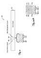
- FIG. 3is a block diagram of an embodiment of the data frame sub-layer 210 of FIG. 2 , represented generally by the sub-layer 300 .
- the sub-layer 300comprises at least one data frame 302 (or optical fiber frame).
- the at least one data frame 302further comprises a delay monitor channel 304 and a delay management channel 306 .
- the delay management channel 306includes an (optional) framing bit 308 and one or more data bits to carry the signal path delay value.
- the delay management channelincludes up to 16 data bits. As shown, the delay management channel comprises five bits. In some embodiments, more than the allocated data bits in one frame are needed to transport the signal path delay value.
- the signal path delay valueis segmented into groups of bits that are transported in sequential frames of the delay management channel.
- the framing bit 308is optional.
- a framing bit flagmay be used to indicate that the signal path delay value was present in the at least one data frame 302 .
- the (optional) framing bit 308is used to indicate the beginning of the first group of bits by setting the value of the framing bit 308 to 1. For the subsequent groups of bits, the framing bit 308 is set to 0.
- a 16-bit signal path delay valueis transported over the delay management channel using four frames with the framing bit 308 of the first frame set to 1 as depicted in FIG. 3A .
- this use of multiple frames to carry a signal path delay valueis referred to as a delay management “superframe.”
- the delay monitor channel 304is used to determine the so-called “transport delay” between adjacent nodes in the network.
- a first nodeuses the delay monitor channel 304 to “ping” the adjacent remote nodes 104 to send back the “ping.” This is accomplished by setting the value of the bit in the delay monitor channel 304 to a “1.”
- the adjacent nodereceives this ping, the adjacent node returns the ping by setting the delay monitor channel 304 to a “1” in its next frame to the node that initiated the ping.
- the transport delay valueis calculated based on the round trip time between the “ping” and the reply.
- there are at least two “ping” bits used in the delay monitor channel 305a forward ping bit and a reverse ping bit.
- the forward ping bitis used
- the reverse ping bitis used.
- the first nodesends the “request” ping
- the adjacent nodesends the “response” ping.
- the first node and the adjacent nodescan ping one another for the data bits carrying the signal path delay value.
- the desired end-to-end transport delay between the host node 102 and the remote nodes 104 1 to 104 Mis programmable for each of the remote nodes 104 1 to 104 M .
- each of the remote nodes 104 1 to 104 Madjust the requested total delay to account for these differences.
- the delay management for the network 100 discussed hereis modular and behaves substantially similar for at least one of a star, a daisy-chain, and a tree network configuration. Additionally, the network 100 automatically adjusts for any changes in the delay due to thermal effects, and for any switching protection changes due to, for example, the signal switches 112 and 114 . Each of the remote nodes 104 1 to 104 M learn the delay going back to the host node 102 from the delay management channel 306 .
- the delay management discussed hereis further divided into at least two distinct operations: (1) Learning a downstream delay (away from the host node 102 ) to an opposing end of the network 100 ; and (2) Propagating an accumulated signal path delay throughout the network 100 .
- the host node 102 and each level of the remote nodes 104 1 to 104 Mare aware which of adjacent remote nodes 104 are downstream and which are upstream. This information is determined in the discovery of the remote nodes 104 as they are introduced into the network 100 .
- the nodesuse the delay monitor channel to determine the transport delay for the nodes that are adjacent to the node in the downstream direction (away from the host node 102 ).
- each signal pathis defined as at least one of a master and a slave signal link, where a downstream signal link for a particular remote (host) node 104 ( 102 ) is defined as the “master” signal link, and an upstream signal link for the same node is defined as the “slave” signal link. Moreover, all signal paths coupled to the host node 102 are designated as master signal links. On each “master” signal link, at least one of the applicable host node or a remote node 104 periodically sets the “ping” bit in the delay monitor channel 304 . The node then receives responses in subsequent data frames 302 sent in corresponding slave signal links. The round trip delay is measured for the remote node associated with the master link. The transport delay for the remote node is determined from this round trip delay by at least one of the following methods.
- a first methodinvolves dividing the round trip delay by two.
- This round trip valueincludes a “turn-around” delay from when the remote node received the “ping” on the master link and when the remote node returns the next frame with the bit set in the delay monitor channel on the slave link.
- This methodhas a resolution of ⁇ 1 ⁇ 2 frames.
- a second methoduses inter-node communication to inform the node calculating the transport delay as to the value of the “turn-around” delay.
- the node calculating the transport delaysubtracts off the “turn-around” delay from the round trip delay prior to dividing the round trip delay by two.
- This methodhas a resolution of ⁇ 1 clock cycle.
- a third methoduses a preconfigured “turn-around” delay.
- the turn-around delayis set to a known value.
- the turn-around delayis subtracted off as in the second method described above with the same resolution.
- the nodes of network 100propagate the signal path delay from node to node.
- host node 102uses the discovered transport delay values for remote nodes 104 1 to 104 3 to generate and send signal path delay to the remote nodes 104 1 to 104 3 .
- each of remote nodes 104 1 to 104 3use the received signal path delay as a basis, along with the transport delay they discovered to their respective adjacent nodes, to generate and send signal path delay information to their adjacent nodes. In this manner, the signal path delay values are propagated through the network 100 .
- the desired end-to-end transport delaywill account for differences in intrinsic processing delay and the differences in signal path delays in the remote nodes 104 1 to 104 M .
- the desired end-to-end transport delayis fixed.
- the remote node processor 108 in each of the remote nodes 104receives a request to set the fixed delay value (e.g., from an SNMP agent present in the application layer 202 ) at each of the antenna ports 110 to a specified value.
- the SNMP agent in the application layer 202subtracts off any known intrinsic processing delays as well as the signal path delay back to the host unit 102 that has been learned as described above.
- the intrinsic processing delaysmay vary for both downstream and upstream signals (also known as forward and reverse paths, respectively).
- Equations 1 and 2illustrate the calculation of the delay that is implemented, e.g., in a FIFO at the remote node, for the forward and reverse paths at the remote node:
- DELAY FWD(Delay Requested ) ⁇ (Delay signal-path ) ⁇ (Delay Intrinsic-SD ) ⁇ (Delay Forward-RF ) (Equation 1)
- the delay that is implemented in the forward pathis the requested delay reduced by three factors; the signal path delay received over the delay management channel (Delay signal-path ), the intrinsic processing delay of the serial to digital conversion (Delay intrinsic-SD ) of the transport interface 107 and the intrinsic delay in the RF to digital conversion (Delay Forward-RF ) of the RF to digital interface 109 .
- DELAY REV(Delay Requested ) ⁇ (Delay signal-path ) ⁇ (Delay Intrinsic-SD ) ⁇ (Delay Reverse-RF ) (Equation 2)
- the delay that is implemented in the reverse pathis the requested delay reduced by three factors; the signal path delay received over the delay management channel (Delay signal-path ) the intrinsic processing delay of the serial to digital conversion (Delay Intrinsic-SD ) of the transport interface 107 and the intrinsic delay in the RF to digital conversion (Delay Reverse-RF ) of the RF to digital interface 109 .
- each of the delays that are subtracted from the Requested Delayis available at the time of the request. Moreover, any request to set a delay that results in a value that is less than zero or greater than DELAY MAX results in a non-operative command.
- the data in a communications channel frame(such as the data frame 302 ) includes framing information, data integrity information (e.g., at least one of forward error correction and cyclical redundancy checking), and the payload data.
- the addition of the delay monitor channel 304 and the delay management channel 306allows the network 100 to automatically synchronize message delivery and propagate end-to-end signal path timings for the antenna ports 110 .
- the delay management methods discussed hereprovides the host node 102 and each of the remote nodes 104 1 to 104 10 with a total signal path delay within the network 100 . Moreover, these methods allow each of the remote nodes 104 1 to 104 10 to independently adjust the transport delay value to maintain a common timing base throughout the network 100 .
- FIG. 4is a flow diagram illustrating a method 400 for managing transport delays in a distributed communications network (e.g., the network 100 ).
- the method 400addresses managing the transport delay between remote nodes and a host node in a point-to-multipoint communications network similar to that of the network 100 .
- the network 100uses the transport delay management described in FIG. 4 to continuously monitor and automatically adjust the signal path delays for the plurality of nodes and achieve the common time base discussed above with respect to FIG. 3 .
- the network 100discovers individual transport delays for any adjacent nodes in the network 100 .
- the host node and each of the remote nodesrecord the individual transport delays between their respective adjacent nodes.
- the network 100generates a signal path delay value based on the transport delays discovered in block 402 .
- the host node and each level of the remote nodesaccount for internal processing delays (e.g., processing delays for transport interfaces in the network 100 ) in calculating the signal path delay.
- the network 100propagates the signal path delay value to each of the adjacent nodes in a first (next) level.
- the signal path delay valueis modified at each of the adjacent nodes for the first (next) level of adjacent nodes, if any are available (block 410 ) and continues to propagate the modified signal path delay value until the each level of the adjacent nodes in the network 100 has a signal path delay value.
- the signal path delay management illustrated in FIG. 4asynchronously adjusts the signal path delay value to achieve the common time base between each of the antenna ports of the network 100 .
- machine-readable media, or storage mediainclude recordable-type media, such as a portable memory device; a hard disk drive (HDD); a random-access memory (RAM); a read-only memory (ROM); transmission-type media, such as digital and analog communications links; and wired or wireless communications links using transmission forms, such as radio frequency and light wave transmissions.
- recordable-type mediasuch as a portable memory device; a hard disk drive (HDD); a random-access memory (RAM); a read-only memory (ROM); transmission-type media, such as digital and analog communications links; and wired or wireless communications links using transmission forms, such as radio frequency and light wave transmissions.
- program productsmay take the form of coded formats that are decoded for actual use in a particular distributed communications network by a combination of digital electronic circuitry and software residing in a programmable processor (e.g., a special-purpose processor or a general-purpose processor in a computer).
- a programmable processore.g., a special-purpose processor or a general-purpose processor in a computer.
- At least one embodiment disclosed hereincan be implemented by computer-executable instructions, such as program product modules, which are executed by the programmable processor.
- the program product modulesinclude routines, programs, objects, data components, data structures, and algorithms that perform particular tasks or implement particular abstract data types.
- the computer-executable instructions, the associated data structures, and the program product modulesrepresent examples of executing the embodiments disclosed.
Landscapes
- Engineering & Computer Science (AREA)
- Computer Networks & Wireless Communication (AREA)
- Signal Processing (AREA)
- Mobile Radio Communication Systems (AREA)
- Data Exchanges In Wide-Area Networks (AREA)
- Computer And Data Communications (AREA)
Abstract
Description
DELAYFWD=(DelayRequested)−(Delaysignal-path)−(DelayIntrinsic-SD)−(DelayForward-RF) (Equation 1)
In this equation, the delay that is implemented in the forward path (signals from the host) is the requested delay reduced by three factors; the signal path delay received over the delay management channel (Delaysignal-path), the intrinsic processing delay of the serial to digital conversion (Delayintrinsic-SD) of the transport interface107 and the intrinsic delay in the RF to digital conversion (DelayForward-RF) of the RF to digital interface109.
DELAYREV=(DelayRequested)−(Delaysignal-path)−(DelayIntrinsic-SD)−(DelayReverse-RF) (Equation 2)
In this equation, the delay that is implemented in the reverse path (signals to the host) is the requested delay reduced by three factors; the signal path delay received over the delay management channel (Delaysignal-path) the intrinsic processing delay of the serial to digital conversion (DelayIntrinsic-SD) of the transport interface107 and the intrinsic delay in the RF to digital conversion (DelayReverse-RF) of the RF to digital interface109.
Claims (15)
Priority Applications (1)
| Application Number | Priority Date | Filing Date | Title |
|---|---|---|---|
| US13/019,571US8509215B2 (en) | 2007-08-15 | 2011-02-02 | Delay management for distributed communications networks |
Applications Claiming Priority (2)
| Application Number | Priority Date | Filing Date | Title |
|---|---|---|---|
| US11/839,086US7948897B2 (en) | 2007-08-15 | 2007-08-15 | Delay management for distributed communications networks |
| US13/019,571US8509215B2 (en) | 2007-08-15 | 2011-02-02 | Delay management for distributed communications networks |
Related Parent Applications (1)
| Application Number | Title | Priority Date | Filing Date |
|---|---|---|---|
| US11/839,086ContinuationUS7948897B2 (en) | 2007-08-15 | 2007-08-15 | Delay management for distributed communications networks |
Publications (2)
| Publication Number | Publication Date |
|---|---|
| US20110122772A1 US20110122772A1 (en) | 2011-05-26 |
| US8509215B2true US8509215B2 (en) | 2013-08-13 |
Family
ID=40351448
Family Applications (2)
| Application Number | Title | Priority Date | Filing Date |
|---|---|---|---|
| US11/839,086Active2028-03-06US7948897B2 (en) | 2007-08-15 | 2007-08-15 | Delay management for distributed communications networks |
| US13/019,571ActiveUS8509215B2 (en) | 2007-08-15 | 2011-02-02 | Delay management for distributed communications networks |
Family Applications Before (1)
| Application Number | Title | Priority Date | Filing Date |
|---|---|---|---|
| US11/839,086Active2028-03-06US7948897B2 (en) | 2007-08-15 | 2007-08-15 | Delay management for distributed communications networks |
Country Status (6)
| Country | Link |
|---|---|
| US (2) | US7948897B2 (en) |
| EP (3) | EP2183886B1 (en) |
| CN (1) | CN101803301A (en) |
| AR (1) | AR067875A1 (en) |
| CL (1) | CL2008002402A1 (en) |
| WO (1) | WO2009023689A2 (en) |
Cited By (38)
| Publication number | Priority date | Publication date | Assignee | Title |
|---|---|---|---|---|
| US9037143B2 (en) | 2010-08-16 | 2015-05-19 | Corning Optical Communications LLC | Remote antenna clusters and related systems, components, and methods supporting digital data signal propagation between remote antenna units |
| US9042732B2 (en) | 2010-05-02 | 2015-05-26 | Corning Optical Communications LLC | Providing digital data services in optical fiber-based distributed radio frequency (RF) communication systems, and related components and methods |
| US9112611B2 (en) | 2009-02-03 | 2015-08-18 | Corning Optical Communications LLC | Optical fiber-based distributed antenna systems, components, and related methods for calibration thereof |
| US9178635B2 (en) | 2014-01-03 | 2015-11-03 | Corning Optical Communications Wireless Ltd | Separation of communication signal sub-bands in distributed antenna systems (DASs) to reduce interference |
| US9184843B2 (en) | 2011-04-29 | 2015-11-10 | Corning Optical Communications LLC | Determining propagation delay of communications in distributed antenna systems, and related components, systems, and methods |
| US9219879B2 (en) | 2009-11-13 | 2015-12-22 | Corning Optical Communications LLC | Radio-over-fiber (ROF) system for protocol-independent wired and/or wireless communication |
| US9240835B2 (en) | 2011-04-29 | 2016-01-19 | Corning Optical Communications LLC | Systems, methods, and devices for increasing radio frequency (RF) power in distributed antenna systems |
| US9247543B2 (en) | 2013-07-23 | 2016-01-26 | Corning Optical Communications Wireless Ltd | Monitoring non-supported wireless spectrum within coverage areas of distributed antenna systems (DASs) |
| US9319138B2 (en) | 2010-02-15 | 2016-04-19 | Corning Optical Communications LLC | Dynamic cell bonding (DCB) for radio-over-fiber (RoF)-based networks and communication systems and related methods |
| US9325429B2 (en) | 2011-02-21 | 2016-04-26 | Corning Optical Communications LLC | Providing digital data services as electrical signals and radio-frequency (RF) communications over optical fiber in distributed communications systems, and related components and methods |
| US9357551B2 (en) | 2014-05-30 | 2016-05-31 | Corning Optical Communications Wireless Ltd | Systems and methods for simultaneous sampling of serial digital data streams from multiple analog-to-digital converters (ADCS), including in distributed antenna systems |
| US9385810B2 (en) | 2013-09-30 | 2016-07-05 | Corning Optical Communications Wireless Ltd | Connection mapping in distributed communication systems |
| US9420542B2 (en) | 2014-09-25 | 2016-08-16 | Corning Optical Communications Wireless Ltd | System-wide uplink band gain control in a distributed antenna system (DAS), based on per band gain control of remote uplink paths in remote units |
| US9455784B2 (en) | 2012-10-31 | 2016-09-27 | Corning Optical Communications Wireless Ltd | Deployable wireless infrastructures and methods of deploying wireless infrastructures |
| US9525488B2 (en) | 2010-05-02 | 2016-12-20 | Corning Optical Communications LLC | Digital data services and/or power distribution in optical fiber-based distributed communications systems providing digital data and radio frequency (RF) communications services, and related components and methods |
| US9602210B2 (en) | 2014-09-24 | 2017-03-21 | Corning Optical Communications Wireless Ltd | Flexible head-end chassis supporting automatic identification and interconnection of radio interface modules and optical interface modules in an optical fiber-based distributed antenna system (DAS) |
| US9621293B2 (en) | 2012-08-07 | 2017-04-11 | Corning Optical Communications Wireless Ltd | Distribution of time-division multiplexed (TDM) management services in a distributed antenna system, and related components, systems, and methods |
| US9647758B2 (en) | 2012-11-30 | 2017-05-09 | Corning Optical Communications Wireless Ltd | Cabling connectivity monitoring and verification |
| US9661781B2 (en) | 2013-07-31 | 2017-05-23 | Corning Optical Communications Wireless Ltd | Remote units for distributed communication systems and related installation methods and apparatuses |
| US9673904B2 (en) | 2009-02-03 | 2017-06-06 | Corning Optical Communications LLC | Optical fiber-based distributed antenna systems, components, and related methods for calibration thereof |
| US9681313B2 (en) | 2015-04-15 | 2017-06-13 | Corning Optical Communications Wireless Ltd | Optimizing remote antenna unit performance using an alternative data channel |
| US9715157B2 (en) | 2013-06-12 | 2017-07-25 | Corning Optical Communications Wireless Ltd | Voltage controlled optical directional coupler |
| US9730228B2 (en) | 2014-08-29 | 2017-08-08 | Corning Optical Communications Wireless Ltd | Individualized gain control of remote uplink band paths in a remote unit in a distributed antenna system (DAS), based on combined uplink power level in the remote unit |
| US9775123B2 (en) | 2014-03-28 | 2017-09-26 | Corning Optical Communications Wireless Ltd. | Individualized gain control of uplink paths in remote units in a distributed antenna system (DAS) based on individual remote unit contribution to combined uplink power |
| US9807700B2 (en) | 2015-02-19 | 2017-10-31 | Corning Optical Communications Wireless Ltd | Offsetting unwanted downlink interference signals in an uplink path in a distributed antenna system (DAS) |
| US9948349B2 (en) | 2015-07-17 | 2018-04-17 | Corning Optical Communications Wireless Ltd | IOT automation and data collection system |
| US9974074B2 (en) | 2013-06-12 | 2018-05-15 | Corning Optical Communications Wireless Ltd | Time-division duplexing (TDD) in distributed communications systems, including distributed antenna systems (DASs) |
| US10096909B2 (en) | 2014-11-03 | 2018-10-09 | Corning Optical Communications Wireless Ltd. | Multi-band monopole planar antennas configured to facilitate improved radio frequency (RF) isolation in multiple-input multiple-output (MIMO) antenna arrangement |
| US10110308B2 (en) | 2014-12-18 | 2018-10-23 | Corning Optical Communications Wireless Ltd | Digital interface modules (DIMs) for flexibly distributing digital and/or analog communications signals in wide-area analog distributed antenna systems (DASs) |
| US10116376B2 (en) | 2014-08-12 | 2018-10-30 | Kathrein-Werke Kg | Method and system for relaying telecommunications signals |
| US10128951B2 (en) | 2009-02-03 | 2018-11-13 | Corning Optical Communications LLC | Optical fiber-based distributed antenna systems, components, and related methods for monitoring and configuring thereof |
| US10135533B2 (en) | 2014-11-13 | 2018-11-20 | Corning Optical Communications Wireless Ltd | Analog distributed antenna systems (DASS) supporting distribution of digital communications signals interfaced from a digital signal source and analog radio frequency (RF) communications signals |
| US10136200B2 (en) | 2012-04-25 | 2018-11-20 | Corning Optical Communications LLC | Distributed antenna system architectures |
| US10187151B2 (en) | 2014-12-18 | 2019-01-22 | Corning Optical Communications Wireless Ltd | Digital-analog interface modules (DAIMs) for flexibly distributing digital and/or analog communications signals in wide-area analog distributed antenna systems (DASs) |
| US10236924B2 (en) | 2016-03-31 | 2019-03-19 | Corning Optical Communications Wireless Ltd | Reducing out-of-channel noise in a wireless distribution system (WDS) |
| US10560214B2 (en) | 2015-09-28 | 2020-02-11 | Corning Optical Communications LLC | Downlink and uplink communication path switching in a time-division duplex (TDD) distributed antenna system (DAS) |
| US10659163B2 (en) | 2014-09-25 | 2020-05-19 | Corning Optical Communications LLC | Supporting analog remote antenna units (RAUs) in digital distributed antenna systems (DASs) using analog RAU digital adaptors |
| US11178609B2 (en) | 2010-10-13 | 2021-11-16 | Corning Optical Communications LLC | Power management for remote antenna units in distributed antenna systems |
Families Citing this family (49)
| Publication number | Priority date | Publication date | Assignee | Title |
|---|---|---|---|---|
| US8380143B2 (en) | 2002-05-01 | 2013-02-19 | Dali Systems Co. Ltd | Power amplifier time-delay invariant predistortion methods and apparatus |
| US8811917B2 (en) | 2002-05-01 | 2014-08-19 | Dali Systems Co. Ltd. | Digital hybrid mode power amplifier system |
| US7966599B1 (en)* | 2006-08-29 | 2011-06-21 | Adobe Systems Incorporated | Runtime library including a virtual file system |
| CN102017553B (en) | 2006-12-26 | 2014-10-15 | 大力系统有限公司 | Method and system for baseband predistortion linearization in a multi-channel broadband communication system |
| US7948897B2 (en)* | 2007-08-15 | 2011-05-24 | Adc Telecommunications, Inc. | Delay management for distributed communications networks |
| US8594133B2 (en) | 2007-10-22 | 2013-11-26 | Corning Mobileaccess Ltd. | Communication system using low bandwidth wires |
| US8520646B1 (en)* | 2008-07-25 | 2013-08-27 | Clearwire Ip Holdings Llc | Ranging of wireless communication networks with distant links |
| US8213401B2 (en) | 2009-01-13 | 2012-07-03 | Adc Telecommunications, Inc. | Systems and methods for IP communication over a distributed antenna system transport |
| USRE47466E1 (en) | 2009-01-13 | 2019-06-25 | Commscope Technologies Llc | Systems and methods for IP communication over a distributed antenna system transport |
| US8346278B2 (en) | 2009-01-13 | 2013-01-01 | Adc Telecommunications, Inc. | Systems and methods for mobile phone location with digital distributed antenna systems |
| FR2949030B1 (en)* | 2009-08-04 | 2012-03-23 | Canon Kk | METHOD AND DEVICE FOR SYNCHRONIZING APPLICATIONS IN A NETWORK |
| US8774232B2 (en)* | 2010-01-08 | 2014-07-08 | Ciena Corporation | Systems and methods of measuring latency and routing thereon in optical networks |
| CN101848119A (en)* | 2010-05-19 | 2010-09-29 | 同济大学 | High-accuracy network round-trip delay measuring method for eliminating system processing time |
| KR101835254B1 (en) | 2010-08-17 | 2018-03-06 | 달리 시스템즈 씨오. 엘티디. | Neutral host architecture for a distributed antenna system |
| CN103597807B (en) | 2010-09-14 | 2015-09-30 | 大理系统有限公司 | Remotely reconfigurable distributed antenna system and method |
| KR101874655B1 (en) | 2011-02-07 | 2018-07-04 | 달리 시스템즈 씨오. 엘티디. | Daisy-chained ring of remote units for a distributed antenna system |
| EP2676389B1 (en) | 2011-02-15 | 2016-08-24 | Telefonaktiebolaget LM Ericsson (publ) | Method of providing a path delay asymmetry for time synchronization between a master and a slave clock across a communciation network |
| US8743718B2 (en)* | 2011-06-21 | 2014-06-03 | Adc Telecommunications, Inc. | End-to-end delay management for distributed communications networks |
| AU2012302074B2 (en) | 2011-08-29 | 2017-02-16 | Commscope Technologies Llc | Configuring a distributed antenna system |
| TWI481218B (en) | 2011-11-10 | 2015-04-11 | Ind Tech Res Inst | Method, apparatus and system for controlling distributed antenna system |
| EP2829152A2 (en) | 2012-03-23 | 2015-01-28 | Corning Optical Communications Wireless Ltd. | Radio-frequency integrated circuit (rfic) chip(s) for providing distributed antenna system functionalities, and related components, systems, and methods |
| EP2832012A1 (en) | 2012-03-30 | 2015-02-04 | Corning Optical Communications LLC | Reducing location-dependent interference in distributed antenna systems operating in multiple-input, multiple-output (mimo) configuration, and related components, systems, and methods |
| CN103580733A (en)* | 2012-07-31 | 2014-02-12 | 财团法人工业技术研究院 | Antenna control method and system |
| DE202013012858U1 (en) | 2012-08-09 | 2021-05-07 | Axel Wireless Ltd. | Capacity-centered digital distributed antenna system |
| CN105308876B (en) | 2012-11-29 | 2018-06-22 | 康宁光电通信有限责任公司 | Remote unit antennas in distributing antenna system combines |
| US9936470B2 (en) | 2013-02-07 | 2018-04-03 | Commscope Technologies Llc | Radio access networks |
| US9414399B2 (en) | 2013-02-07 | 2016-08-09 | Commscope Technologies Llc | Radio access networks |
| US9380466B2 (en) | 2013-02-07 | 2016-06-28 | Commscope Technologies Llc | Radio access networks |
| US9492741B2 (en) | 2013-05-22 | 2016-11-15 | Microsoft Technology Licensing, Llc | Wireless gaming protocol |
| US9450689B2 (en) | 2013-10-07 | 2016-09-20 | Commscope Technologies Llc | Systems and methods for delay management in distributed antenna system with direct digital interface to base station |
| US20170250927A1 (en)* | 2013-12-23 | 2017-08-31 | Dali Systems Co. Ltd. | Virtual radio access network using software-defined network of remotes and digital multiplexing switches |
| CN104793573A (en)* | 2014-01-17 | 2015-07-22 | 中国联合网络通信集团有限公司 | Monitoring system and monitoring method thereof |
| WO2015191530A2 (en) | 2014-06-09 | 2015-12-17 | Airvana Lp | Radio access networks |
| US9525472B2 (en) | 2014-07-30 | 2016-12-20 | Corning Incorporated | Reducing location-dependent destructive interference in distributed antenna systems (DASS) operating in multiple-input, multiple-output (MIMO) configuration, and related components, systems, and methods |
| US9307506B1 (en)* | 2014-09-09 | 2016-04-05 | Sprint Communications Company L.P. | Implementation of a fiber distributed antenna system network while maintaining synchronization |
| CA2961696A1 (en) | 2014-09-23 | 2016-03-31 | Axell Wireless Ltd. | Automatic mapping and handling pim and other uplink interferences in digital distributed antenna systems |
| US9184960B1 (en) | 2014-09-25 | 2015-11-10 | Corning Optical Communications Wireless Ltd | Frequency shifting a communications signal(s) in a multi-frequency distributed antenna system (DAS) to avoid or reduce frequency interference |
| US9729267B2 (en) | 2014-12-11 | 2017-08-08 | Corning Optical Communications Wireless Ltd | Multiplexing two separate optical links with the same wavelength using asymmetric combining and splitting |
| EP3238352A4 (en) | 2014-12-23 | 2018-08-22 | Axell Wireless Ltd. | Harmonizing noise aggregation and noise management in distributed antenna system |
| KR101868964B1 (en)* | 2014-12-30 | 2018-06-19 | 주식회사 쏠리드 | Node unit capable of measuring and compensation transmission delay and distributed antenna system including it |
| KR102153396B1 (en) | 2014-12-30 | 2020-09-08 | 주식회사 쏠리드 | Node unit capable of measuring delay and distributed antenna system including it |
| US9866494B2 (en) | 2015-11-04 | 2018-01-09 | Microsoft Technology Licensing, Llc | Wireless communication using delayed frame transmission |
| CN109428742B (en)* | 2017-08-22 | 2020-12-15 | 华为技术有限公司 | Delay-based transmission path control method, network controller and system |
| KR101959640B1 (en)* | 2017-12-15 | 2019-03-18 | 연세대학교 산학협력단 | Latency Managing Apparatus and Method for Software Defined Networks, and Recording Medium Thereof |
| CN112640331A (en) | 2018-08-29 | 2021-04-09 | 康普技术有限责任公司 | Clock synchronization in a centralized radio access network with multiple controllers |
| CN109462493B (en)* | 2018-09-13 | 2021-12-28 | 国网浙江省电力有限公司丽水供电公司 | Local area network monitoring method based on PING |
| JP7192608B2 (en)* | 2019-03-26 | 2022-12-20 | オムロン株式会社 | Network management device, management method, management program and recording medium |
| US11431425B2 (en)* | 2020-09-24 | 2022-08-30 | Corning Research & Development Corporation | Measuring an end-to-end delay(s) in a distributed communications system |
| US20230403179A1 (en)* | 2022-06-08 | 2023-12-14 | Analog Devices, Inc. | A2b cable length detection |
Citations (34)
| Publication number | Priority date | Publication date | Assignee | Title |
|---|---|---|---|---|
| US4183054A (en) | 1977-09-30 | 1980-01-08 | Harris Corporation | Digital, frequency-translated, plural-channel, vestigial sideband television communication system |
| US4611323A (en) | 1983-05-24 | 1986-09-09 | Ant Nachrichtentechnik Gmbh | Method for transmitting digitally coded analog signals |
| US4628501A (en) | 1983-12-29 | 1986-12-09 | The United States Of America As Represented By The Secretary Of The Army | Optical communications systems |
| US4654843A (en) | 1982-09-17 | 1987-03-31 | U.S. Philips Corporation | Signal distribution system |
| US4691292A (en) | 1983-04-13 | 1987-09-01 | Rca Corporation | System for digital multiband filtering |
| EP0391597A2 (en) | 1989-04-04 | 1990-10-10 | AT&T Corp. | Optical fiber microcellular mobile radio |
| US4999831A (en) | 1989-10-19 | 1991-03-12 | United Telecommunications, Inc. | Synchronous quantized subcarrier multiplexer for digital transport of video, voice and data |
| WO1991015927A1 (en) | 1990-04-10 | 1991-10-17 | British Telecommunications Public Limited Company | Signal distribution |
| US5193109A (en) | 1989-02-06 | 1993-03-09 | Pactel Corporation | Zoned microcell with sector scanning for cellular telephone system |
| US5243598A (en) | 1991-04-02 | 1993-09-07 | Pactel Corporation | Microcell system in digital cellular |
| US5321849A (en) | 1991-05-22 | 1994-06-14 | Southwestern Bell Technology Resources, Inc. | System for controlling signal level at both ends of a transmission link based on a detected valve |
| US5339184A (en) | 1992-06-15 | 1994-08-16 | Gte Laboratories Incorporated | Fiber optic antenna remoting for multi-sector cell sites |
| KR950704866A (en) | 1993-08-27 | 1995-11-20 | 하비 피. 화이트 | DUAL DISTRIBUTIED ANTENNA SYSTEM |
| US5506847A (en) | 1993-04-26 | 1996-04-09 | Kabushiki Kaisha Toshiba | ATM-lan system using broadcast channel for transferring link setting and chaining requests |
| US6205120B1 (en)* | 1998-03-13 | 2001-03-20 | Packeteer, Inc. | Method for transparently determining and setting an optimal minimum required TCP window size |
| US6430160B1 (en)* | 2000-02-29 | 2002-08-06 | Verizon Laboratories Inc. | Estimating data delays from poisson probe delays |
| KR20030001491A (en) | 2000-05-15 | 2003-01-06 | 노키아 코포레이션 | Method to calculate true round trip propagation delay and user equipment location in wcdma/utran |
| US6539026B1 (en)* | 1999-03-15 | 2003-03-25 | Cisco Technology, Inc. | Apparatus and method for delay management in a data communications network |
| KR20030059259A (en) | 2000-11-21 | 2003-07-07 | 인터내셔널 비지네스 머신즈 코포레이션 | Costs in data networks |
| US20030185571A1 (en)* | 2002-01-15 | 2003-10-02 | Hyun-Pyo Lee | Method and apparatus for compensating for optical transmission delay in a synchronous mobile communication system using synchronous digital hierarchy |
| US6647210B1 (en)* | 1999-04-16 | 2003-11-11 | Fujitsu Limited | Delay adjustment unit and method, optical network unit, and communication system |
| US6690892B1 (en)* | 2000-11-20 | 2004-02-10 | Quantum Bridge, Communications, Inc. | Method and apparatus for controlling delay in a shared communications network |
| US6700893B1 (en)* | 1999-11-15 | 2004-03-02 | Koninklijke Philips Electronics N.V. | System and method for controlling the delay budget of a decoder buffer in a streaming data receiver |
| US20040165532A1 (en) | 2002-06-07 | 2004-08-26 | Poor Robert Dunbar | Ad hoc wireless network using gradient routing |
| US6791949B1 (en) | 2000-04-28 | 2004-09-14 | Raytheon Company | Network protocol for wireless ad hoc networks |
| US6977942B2 (en)* | 1999-12-30 | 2005-12-20 | Nokia Corporation | Method and a device for timing the processing of data packets |
| US7035210B2 (en)* | 2001-07-12 | 2006-04-25 | Telefonaktiebolaget Lm Ericsson (Publ) | Media stream delay monitoring for node |
| US7058050B2 (en) | 2000-12-01 | 2006-06-06 | Telefonaktiebolaget L M Ericsson (Publ) | Flexible inter-network communication scheduling |
| CN1812350A (en) | 2005-01-27 | 2006-08-02 | 华为技术有限公司 | One-way delay measuring method |
| US7113536B2 (en) | 2001-04-16 | 2006-09-26 | Telefonaktiebolaget L M Ericsson (Publ) | Rendezvous point interpiconet scheduling |
| US20060274664A1 (en)* | 2005-06-02 | 2006-12-07 | Harshang Pandya | Characterization of Voice over Internet Protocol (VoIP) network |
| US7161926B2 (en) | 2001-07-03 | 2007-01-09 | Sensoria Corporation | Low-latency multi-hop ad hoc wireless network |
| US7184920B2 (en)* | 2004-01-19 | 2007-02-27 | Fujitsu Limited | Delay measurement system |
| US20090046586A1 (en) | 2007-08-15 | 2009-02-19 | Adc Telecommunications, Inc. | Delay management for distributed communications networks |
Family Cites Families (2)
| Publication number | Priority date | Publication date | Assignee | Title |
|---|---|---|---|---|
| GB2197531B (en)* | 1986-11-08 | 1991-02-06 | Stc Plc | Distributed feedback laser |
| JP2000101597A (en)* | 1998-09-24 | 2000-04-07 | Nec Corp | Inter-node frame phase synchronization system and method |
- 2007
- 2007-08-15USUS11/839,086patent/US7948897B2/enactiveActive
- 2008
- 2008-08-07ARARP080103454Apatent/AR067875A1/ennot_activeApplication Discontinuation
- 2008-08-13EPEP08827432.9Apatent/EP2183886B1/enactiveActive
- 2008-08-13WOPCT/US2008/072953patent/WO2009023689A2/enactiveApplication Filing
- 2008-08-13EPEP17020025.7Apatent/EP3188381B1/ennot_activeNot-in-force
- 2008-08-13CNCN200880103706Apatent/CN101803301A/enactivePending
- 2008-08-13EPEP19171668.7Apatent/EP3540982B1/enactiveActive
- 2008-08-14CLCL2008002402Apatent/CL2008002402A1/enunknown
- 2011
- 2011-02-02USUS13/019,571patent/US8509215B2/enactiveActive
Patent Citations (34)
| Publication number | Priority date | Publication date | Assignee | Title |
|---|---|---|---|---|
| US4183054A (en) | 1977-09-30 | 1980-01-08 | Harris Corporation | Digital, frequency-translated, plural-channel, vestigial sideband television communication system |
| US4654843A (en) | 1982-09-17 | 1987-03-31 | U.S. Philips Corporation | Signal distribution system |
| US4691292A (en) | 1983-04-13 | 1987-09-01 | Rca Corporation | System for digital multiband filtering |
| US4611323A (en) | 1983-05-24 | 1986-09-09 | Ant Nachrichtentechnik Gmbh | Method for transmitting digitally coded analog signals |
| US4628501A (en) | 1983-12-29 | 1986-12-09 | The United States Of America As Represented By The Secretary Of The Army | Optical communications systems |
| US5193109A (en) | 1989-02-06 | 1993-03-09 | Pactel Corporation | Zoned microcell with sector scanning for cellular telephone system |
| EP0391597A2 (en) | 1989-04-04 | 1990-10-10 | AT&T Corp. | Optical fiber microcellular mobile radio |
| US4999831A (en) | 1989-10-19 | 1991-03-12 | United Telecommunications, Inc. | Synchronous quantized subcarrier multiplexer for digital transport of video, voice and data |
| WO1991015927A1 (en) | 1990-04-10 | 1991-10-17 | British Telecommunications Public Limited Company | Signal distribution |
| US5243598A (en) | 1991-04-02 | 1993-09-07 | Pactel Corporation | Microcell system in digital cellular |
| US5321849A (en) | 1991-05-22 | 1994-06-14 | Southwestern Bell Technology Resources, Inc. | System for controlling signal level at both ends of a transmission link based on a detected valve |
| US5339184A (en) | 1992-06-15 | 1994-08-16 | Gte Laboratories Incorporated | Fiber optic antenna remoting for multi-sector cell sites |
| US5506847A (en) | 1993-04-26 | 1996-04-09 | Kabushiki Kaisha Toshiba | ATM-lan system using broadcast channel for transferring link setting and chaining requests |
| KR950704866A (en) | 1993-08-27 | 1995-11-20 | 하비 피. 화이트 | DUAL DISTRIBUTIED ANTENNA SYSTEM |
| US6205120B1 (en)* | 1998-03-13 | 2001-03-20 | Packeteer, Inc. | Method for transparently determining and setting an optimal minimum required TCP window size |
| US6539026B1 (en)* | 1999-03-15 | 2003-03-25 | Cisco Technology, Inc. | Apparatus and method for delay management in a data communications network |
| US6647210B1 (en)* | 1999-04-16 | 2003-11-11 | Fujitsu Limited | Delay adjustment unit and method, optical network unit, and communication system |
| US6700893B1 (en)* | 1999-11-15 | 2004-03-02 | Koninklijke Philips Electronics N.V. | System and method for controlling the delay budget of a decoder buffer in a streaming data receiver |
| US6977942B2 (en)* | 1999-12-30 | 2005-12-20 | Nokia Corporation | Method and a device for timing the processing of data packets |
| US6430160B1 (en)* | 2000-02-29 | 2002-08-06 | Verizon Laboratories Inc. | Estimating data delays from poisson probe delays |
| US6791949B1 (en) | 2000-04-28 | 2004-09-14 | Raytheon Company | Network protocol for wireless ad hoc networks |
| KR20030001491A (en) | 2000-05-15 | 2003-01-06 | 노키아 코포레이션 | Method to calculate true round trip propagation delay and user equipment location in wcdma/utran |
| US6690892B1 (en)* | 2000-11-20 | 2004-02-10 | Quantum Bridge, Communications, Inc. | Method and apparatus for controlling delay in a shared communications network |
| KR20030059259A (en) | 2000-11-21 | 2003-07-07 | 인터내셔널 비지네스 머신즈 코포레이션 | Costs in data networks |
| US7058050B2 (en) | 2000-12-01 | 2006-06-06 | Telefonaktiebolaget L M Ericsson (Publ) | Flexible inter-network communication scheduling |
| US7113536B2 (en) | 2001-04-16 | 2006-09-26 | Telefonaktiebolaget L M Ericsson (Publ) | Rendezvous point interpiconet scheduling |
| US7161926B2 (en) | 2001-07-03 | 2007-01-09 | Sensoria Corporation | Low-latency multi-hop ad hoc wireless network |
| US7035210B2 (en)* | 2001-07-12 | 2006-04-25 | Telefonaktiebolaget Lm Ericsson (Publ) | Media stream delay monitoring for node |
| US20030185571A1 (en)* | 2002-01-15 | 2003-10-02 | Hyun-Pyo Lee | Method and apparatus for compensating for optical transmission delay in a synchronous mobile communication system using synchronous digital hierarchy |
| US20040165532A1 (en) | 2002-06-07 | 2004-08-26 | Poor Robert Dunbar | Ad hoc wireless network using gradient routing |
| US7184920B2 (en)* | 2004-01-19 | 2007-02-27 | Fujitsu Limited | Delay measurement system |
| CN1812350A (en) | 2005-01-27 | 2006-08-02 | 华为技术有限公司 | One-way delay measuring method |
| US20060274664A1 (en)* | 2005-06-02 | 2006-12-07 | Harshang Pandya | Characterization of Voice over Internet Protocol (VoIP) network |
| US20090046586A1 (en) | 2007-08-15 | 2009-02-19 | Adc Telecommunications, Inc. | Delay management for distributed communications networks |
Non-Patent Citations (7)
| Title |
|---|
| Chile Patent Office, "First Office Action", at least as early as Feb. 25, 2010, pp. 1-6, Published in: CL. |
| Chile Patent Office, "Second Office Action", at least as early as Oct. 6, 2010, pp. 1-5, Published in: CL. |
| Chinese Patent Office, "Office Action", "from Foreign Counterpart of U.S. Appl. No. 11/839,086", Apr. 8, 2013, pp. 1-24, Published in: CN. |
| Chinese Patent Office, "Office Action", Jan. 18, 2012, Published in: CN. |
| Chinese Patent Office, "Second Office Action", "from Foreign Counterpart of U.S. Application", Sep. 7, 2012, p. (s) 1-18, Published in: CN. |
| Grace, Martin K., "Synchronous Quantized Subcarrier Multiplexing for Transport of Video, Voice and Data", "IEEE Journal on Selected Areas in Communications", Sep. 1990, pp. 1351-1358, vol. 8, No. 7, Publisher: IEEE. |
| Harvey et al., "Cordless Communications Utilising Radio Over Fibre Techniques for the Local Loop", "IEEE International Conference on Communications", Jun. 1991, pp. 1171-1175, Publisher: IEEE. |
Cited By (71)
| Publication number | Priority date | Publication date | Assignee | Title |
|---|---|---|---|---|
| US9900097B2 (en) | 2009-02-03 | 2018-02-20 | Corning Optical Communications LLC | Optical fiber-based distributed antenna systems, components, and related methods for calibration thereof |
| US9673904B2 (en) | 2009-02-03 | 2017-06-06 | Corning Optical Communications LLC | Optical fiber-based distributed antenna systems, components, and related methods for calibration thereof |
| US9112611B2 (en) | 2009-02-03 | 2015-08-18 | Corning Optical Communications LLC | Optical fiber-based distributed antenna systems, components, and related methods for calibration thereof |
| US10128951B2 (en) | 2009-02-03 | 2018-11-13 | Corning Optical Communications LLC | Optical fiber-based distributed antenna systems, components, and related methods for monitoring and configuring thereof |
| US10153841B2 (en) | 2009-02-03 | 2018-12-11 | Corning Optical Communications LLC | Optical fiber-based distributed antenna systems, components, and related methods for calibration thereof |
| US9485022B2 (en) | 2009-11-13 | 2016-11-01 | Corning Optical Communications LLC | Radio-over-fiber (ROF) system for protocol-independent wired and/or wireless communication |
| US9219879B2 (en) | 2009-11-13 | 2015-12-22 | Corning Optical Communications LLC | Radio-over-fiber (ROF) system for protocol-independent wired and/or wireless communication |
| US9729238B2 (en) | 2009-11-13 | 2017-08-08 | Corning Optical Communications LLC | Radio-over-fiber (ROF) system for protocol-independent wired and/or wireless communication |
| US9319138B2 (en) | 2010-02-15 | 2016-04-19 | Corning Optical Communications LLC | Dynamic cell bonding (DCB) for radio-over-fiber (RoF)-based networks and communication systems and related methods |
| US9853732B2 (en) | 2010-05-02 | 2017-12-26 | Corning Optical Communications LLC | Digital data services and/or power distribution in optical fiber-based distributed communications systems providing digital data and radio frequency (RF) communications services, and related components and methods |
| US9270374B2 (en) | 2010-05-02 | 2016-02-23 | Corning Optical Communications LLC | Providing digital data services in optical fiber-based distributed radio frequency (RF) communications systems, and related components and methods |
| US9525488B2 (en) | 2010-05-02 | 2016-12-20 | Corning Optical Communications LLC | Digital data services and/or power distribution in optical fiber-based distributed communications systems providing digital data and radio frequency (RF) communications services, and related components and methods |
| US9042732B2 (en) | 2010-05-02 | 2015-05-26 | Corning Optical Communications LLC | Providing digital data services in optical fiber-based distributed radio frequency (RF) communication systems, and related components and methods |
| US10014944B2 (en) | 2010-08-16 | 2018-07-03 | Corning Optical Communications LLC | Remote antenna clusters and related systems, components, and methods supporting digital data signal propagation between remote antenna units |
| US9037143B2 (en) | 2010-08-16 | 2015-05-19 | Corning Optical Communications LLC | Remote antenna clusters and related systems, components, and methods supporting digital data signal propagation between remote antenna units |
| US11178609B2 (en) | 2010-10-13 | 2021-11-16 | Corning Optical Communications LLC | Power management for remote antenna units in distributed antenna systems |
| US11212745B2 (en) | 2010-10-13 | 2021-12-28 | Corning Optical Communications LLC | Power management for remote antenna units in distributed antenna systems |
| US11224014B2 (en) | 2010-10-13 | 2022-01-11 | Corning Optical Communications LLC | Power management for remote antenna units in distributed antenna systems |
| US11671914B2 (en) | 2010-10-13 | 2023-06-06 | Corning Optical Communications LLC | Power management for remote antenna units in distributed antenna systems |
| US9813164B2 (en) | 2011-02-21 | 2017-11-07 | Corning Optical Communications LLC | Providing digital data services as electrical signals and radio-frequency (RF) communications over optical fiber in distributed communications systems, and related components and methods |
| US9325429B2 (en) | 2011-02-21 | 2016-04-26 | Corning Optical Communications LLC | Providing digital data services as electrical signals and radio-frequency (RF) communications over optical fiber in distributed communications systems, and related components and methods |
| US10205538B2 (en) | 2011-02-21 | 2019-02-12 | Corning Optical Communications LLC | Providing digital data services as electrical signals and radio-frequency (RF) communications over optical fiber in distributed communications systems, and related components and methods |
| US9184843B2 (en) | 2011-04-29 | 2015-11-10 | Corning Optical Communications LLC | Determining propagation delay of communications in distributed antenna systems, and related components, systems, and methods |
| US10148347B2 (en) | 2011-04-29 | 2018-12-04 | Corning Optical Communications LLC | Systems, methods, and devices for increasing radio frequency (RF) power in distributed antenna systems |
| US9369222B2 (en) | 2011-04-29 | 2016-06-14 | Corning Optical Communications LLC | Determining propagation delay of communications in distributed antenna systems, and related components, systems, and methods |
| US9806797B2 (en) | 2011-04-29 | 2017-10-31 | Corning Optical Communications LLC | Systems, methods, and devices for increasing radio frequency (RF) power in distributed antenna systems |
| US9240835B2 (en) | 2011-04-29 | 2016-01-19 | Corning Optical Communications LLC | Systems, methods, and devices for increasing radio frequency (RF) power in distributed antenna systems |
| US9807722B2 (en) | 2011-04-29 | 2017-10-31 | Corning Optical Communications LLC | Determining propagation delay of communications in distributed antenna systems, and related components, systems, and methods |
| US10349156B2 (en) | 2012-04-25 | 2019-07-09 | Corning Optical Communications LLC | Distributed antenna system architectures |
| US10136200B2 (en) | 2012-04-25 | 2018-11-20 | Corning Optical Communications LLC | Distributed antenna system architectures |
| US9973968B2 (en) | 2012-08-07 | 2018-05-15 | Corning Optical Communications Wireless Ltd | Distribution of time-division multiplexed (TDM) management services in a distributed antenna system, and related components, systems, and methods |
| US9621293B2 (en) | 2012-08-07 | 2017-04-11 | Corning Optical Communications Wireless Ltd | Distribution of time-division multiplexed (TDM) management services in a distributed antenna system, and related components, systems, and methods |
| US9455784B2 (en) | 2012-10-31 | 2016-09-27 | Corning Optical Communications Wireless Ltd | Deployable wireless infrastructures and methods of deploying wireless infrastructures |
| US9647758B2 (en) | 2012-11-30 | 2017-05-09 | Corning Optical Communications Wireless Ltd | Cabling connectivity monitoring and verification |
| US10361782B2 (en) | 2012-11-30 | 2019-07-23 | Corning Optical Communications LLC | Cabling connectivity monitoring and verification |
| US9974074B2 (en) | 2013-06-12 | 2018-05-15 | Corning Optical Communications Wireless Ltd | Time-division duplexing (TDD) in distributed communications systems, including distributed antenna systems (DASs) |
| US9715157B2 (en) | 2013-06-12 | 2017-07-25 | Corning Optical Communications Wireless Ltd | Voltage controlled optical directional coupler |
| US11792776B2 (en) | 2013-06-12 | 2023-10-17 | Corning Optical Communications LLC | Time-division duplexing (TDD) in distributed communications systems, including distributed antenna systems (DASs) |
| US11291001B2 (en) | 2013-06-12 | 2022-03-29 | Corning Optical Communications LLC | Time-division duplexing (TDD) in distributed communications systems, including distributed antenna systems (DASs) |
| US9967754B2 (en) | 2013-07-23 | 2018-05-08 | Corning Optical Communications Wireless Ltd | Monitoring non-supported wireless spectrum within coverage areas of distributed antenna systems (DASs) |
| US9526020B2 (en) | 2013-07-23 | 2016-12-20 | Corning Optical Communications Wireless Ltd | Monitoring non-supported wireless spectrum within coverage areas of distributed antenna systems (DASs) |
| US10292056B2 (en) | 2013-07-23 | 2019-05-14 | Corning Optical Communications LLC | Monitoring non-supported wireless spectrum within coverage areas of distributed antenna systems (DASs) |
| US9247543B2 (en) | 2013-07-23 | 2016-01-26 | Corning Optical Communications Wireless Ltd | Monitoring non-supported wireless spectrum within coverage areas of distributed antenna systems (DASs) |
| US9661781B2 (en) | 2013-07-31 | 2017-05-23 | Corning Optical Communications Wireless Ltd | Remote units for distributed communication systems and related installation methods and apparatuses |
| US9385810B2 (en) | 2013-09-30 | 2016-07-05 | Corning Optical Communications Wireless Ltd | Connection mapping in distributed communication systems |
| US9178635B2 (en) | 2014-01-03 | 2015-11-03 | Corning Optical Communications Wireless Ltd | Separation of communication signal sub-bands in distributed antenna systems (DASs) to reduce interference |
| US9775123B2 (en) | 2014-03-28 | 2017-09-26 | Corning Optical Communications Wireless Ltd. | Individualized gain control of uplink paths in remote units in a distributed antenna system (DAS) based on individual remote unit contribution to combined uplink power |
| US9807772B2 (en) | 2014-05-30 | 2017-10-31 | Corning Optical Communications Wireless Ltd. | Systems and methods for simultaneous sampling of serial digital data streams from multiple analog-to-digital converters (ADCs), including in distributed antenna systems |
| US9357551B2 (en) | 2014-05-30 | 2016-05-31 | Corning Optical Communications Wireless Ltd | Systems and methods for simultaneous sampling of serial digital data streams from multiple analog-to-digital converters (ADCS), including in distributed antenna systems |
| US10116376B2 (en) | 2014-08-12 | 2018-10-30 | Kathrein-Werke Kg | Method and system for relaying telecommunications signals |
| US9730228B2 (en) | 2014-08-29 | 2017-08-08 | Corning Optical Communications Wireless Ltd | Individualized gain control of remote uplink band paths in a remote unit in a distributed antenna system (DAS), based on combined uplink power level in the remote unit |
| US10397929B2 (en) | 2014-08-29 | 2019-08-27 | Corning Optical Communications LLC | Individualized gain control of remote uplink band paths in a remote unit in a distributed antenna system (DAS), based on combined uplink power level in the remote unit |
| US9929810B2 (en) | 2014-09-24 | 2018-03-27 | Corning Optical Communications Wireless Ltd | Flexible head-end chassis supporting automatic identification and interconnection of radio interface modules and optical interface modules in an optical fiber-based distributed antenna system (DAS) |
| US9602210B2 (en) | 2014-09-24 | 2017-03-21 | Corning Optical Communications Wireless Ltd | Flexible head-end chassis supporting automatic identification and interconnection of radio interface modules and optical interface modules in an optical fiber-based distributed antenna system (DAS) |
| US9788279B2 (en) | 2014-09-25 | 2017-10-10 | Corning Optical Communications Wireless Ltd | System-wide uplink band gain control in a distributed antenna system (DAS), based on per-band gain control of remote uplink paths in remote units |
| US9420542B2 (en) | 2014-09-25 | 2016-08-16 | Corning Optical Communications Wireless Ltd | System-wide uplink band gain control in a distributed antenna system (DAS), based on per band gain control of remote uplink paths in remote units |
| US10659163B2 (en) | 2014-09-25 | 2020-05-19 | Corning Optical Communications LLC | Supporting analog remote antenna units (RAUs) in digital distributed antenna systems (DASs) using analog RAU digital adaptors |
| US10096909B2 (en) | 2014-11-03 | 2018-10-09 | Corning Optical Communications Wireless Ltd. | Multi-band monopole planar antennas configured to facilitate improved radio frequency (RF) isolation in multiple-input multiple-output (MIMO) antenna arrangement |
| US10135533B2 (en) | 2014-11-13 | 2018-11-20 | Corning Optical Communications Wireless Ltd | Analog distributed antenna systems (DASS) supporting distribution of digital communications signals interfaced from a digital signal source and analog radio frequency (RF) communications signals |
| US10523326B2 (en) | 2014-11-13 | 2019-12-31 | Corning Optical Communications LLC | Analog distributed antenna systems (DASS) supporting distribution of digital communications signals interfaced from a digital signal source and analog radio frequency (RF) communications signals |
| US10361783B2 (en) | 2014-12-18 | 2019-07-23 | Corning Optical Communications LLC | Digital interface modules (DIMs) for flexibly distributing digital and/or analog communications signals in wide-area analog distributed antenna systems (DASs) |
| US10523327B2 (en) | 2014-12-18 | 2019-12-31 | Corning Optical Communications LLC | Digital-analog interface modules (DAIMs) for flexibly distributing digital and/or analog communications signals in wide-area analog distributed antenna systems (DASs) |
| US10187151B2 (en) | 2014-12-18 | 2019-01-22 | Corning Optical Communications Wireless Ltd | Digital-analog interface modules (DAIMs) for flexibly distributing digital and/or analog communications signals in wide-area analog distributed antenna systems (DASs) |
| US10110308B2 (en) | 2014-12-18 | 2018-10-23 | Corning Optical Communications Wireless Ltd | Digital interface modules (DIMs) for flexibly distributing digital and/or analog communications signals in wide-area analog distributed antenna systems (DASs) |
| US10292114B2 (en) | 2015-02-19 | 2019-05-14 | Corning Optical Communications LLC | Offsetting unwanted downlink interference signals in an uplink path in a distributed antenna system (DAS) |
| US9807700B2 (en) | 2015-02-19 | 2017-10-31 | Corning Optical Communications Wireless Ltd | Offsetting unwanted downlink interference signals in an uplink path in a distributed antenna system (DAS) |
| US10009094B2 (en) | 2015-04-15 | 2018-06-26 | Corning Optical Communications Wireless Ltd | Optimizing remote antenna unit performance using an alternative data channel |
| US9681313B2 (en) | 2015-04-15 | 2017-06-13 | Corning Optical Communications Wireless Ltd | Optimizing remote antenna unit performance using an alternative data channel |
| US9948349B2 (en) | 2015-07-17 | 2018-04-17 | Corning Optical Communications Wireless Ltd | IOT automation and data collection system |
| US10560214B2 (en) | 2015-09-28 | 2020-02-11 | Corning Optical Communications LLC | Downlink and uplink communication path switching in a time-division duplex (TDD) distributed antenna system (DAS) |
| US10236924B2 (en) | 2016-03-31 | 2019-03-19 | Corning Optical Communications Wireless Ltd | Reducing out-of-channel noise in a wireless distribution system (WDS) |
Also Published As
| Publication number | Publication date |
|---|---|
| EP2183886A2 (en) | 2010-05-12 |
| US20110122772A1 (en) | 2011-05-26 |
| WO2009023689A2 (en) | 2009-02-19 |
| EP2183886B1 (en) | 2017-01-25 |
| US7948897B2 (en) | 2011-05-24 |
| WO2009023689A3 (en) | 2009-05-22 |
| EP3540982A1 (en) | 2019-09-18 |
| US20090046586A1 (en) | 2009-02-19 |
| EP3540982B1 (en) | 2020-12-16 |
| EP3188381A1 (en) | 2017-07-05 |
| AR067875A1 (en) | 2009-10-28 |
| CL2008002402A1 (en) | 2009-01-09 |
| EP3188381B1 (en) | 2019-05-01 |
| CN101803301A (en) | 2010-08-11 |
| EP2183886A4 (en) | 2015-03-04 |
Similar Documents
| Publication | Publication Date | Title |
|---|---|---|
| US8509215B2 (en) | Delay management for distributed communications networks | |
| US9813175B2 (en) | Method for detecting timing references affected by a change in path delay asymmetry between nodes in a communication network | |
| US10404392B2 (en) | Method and apparatus for determining propagation delay in a communications network | |
| CN113259038B (en) | Time synchronization method, node, device and storage medium | |
| WO2013156904A1 (en) | Ring based precise time data network clock phase adjustments | |
| WO2001095550A2 (en) | Distributing time information in a communication network | |
| US9172525B2 (en) | Method and device for compensating for time path | |
| CN102195735A (en) | Time synchronization method for multi-subsystem equipment and subsystem | |
| US20240146433A1 (en) | Time slot allocation processing method, device and storage medium | |
| US9191844B2 (en) | Systems and methods for phase determination over a wireless link | |
| CN104767633A (en) | An Industrial Ethernet System | |
| KR20120051632A (en) | Method for clock synchronization in distributed system having ring topology and apparatus for the same | |
| WO2023115403A1 (en) | Methods and network devices for ptp clock synchronization | |
| CN114389733B (en) | PTP master clock device, clock synchronization method, and storage medium | |
| EP3741059B1 (en) | Automatic clock phase synchronization in otn multi-chassis system with fail over mechanism | |
| US11924592B2 (en) | Fast flow-controlled and clock-distributed optical switching system for optical data center network | |
| CN104025483A (en) | Services, systems and methods for precisely estimating a delay within a network | |
| CN120017212A (en) | Parameter determination method, communication device and system | |
| WO2024205863A1 (en) | Artificially manipulating delay in radio access networks and distributed antenna systems | |
| WO2017071759A1 (en) | Communication network control method and controller |
Legal Events
| Date | Code | Title | Description |
|---|---|---|---|
| AS | Assignment | Owner name:ADC TELECOMMUNICATIONS, INC., MINNESOTA Free format text:ASSIGNMENT OF ASSIGNORS INTEREST;ASSIGNORS:STUART, STEVEN B.;HEDIN, JOHN M.;REEL/FRAME:025733/0918 Effective date:20070813 | |
| STCF | Information on status: patent grant | Free format text:PATENTED CASE | |
| AS | Assignment | Owner name:TYCO ELECTRONICS SERVICES GMBH, SWITZERLAND Free format text:ASSIGNMENT OF ASSIGNORS INTEREST;ASSIGNOR:ADC TELECOMMUNICATIONS, INC.;REEL/FRAME:036060/0174 Effective date:20110930 | |
| AS | Assignment | Owner name:COMMSCOPE EMEA LIMITED, IRELAND Free format text:ASSIGNMENT OF ASSIGNORS INTEREST;ASSIGNOR:TYCO ELECTRONICS SERVICES GMBH;REEL/FRAME:036956/0001 Effective date:20150828 | |
| AS | Assignment | Owner name:COMMSCOPE TECHNOLOGIES LLC, NORTH CAROLINA Free format text:ASSIGNMENT OF ASSIGNORS INTEREST;ASSIGNOR:COMMSCOPE EMEA LIMITED;REEL/FRAME:037012/0001 Effective date:20150828 | |
| AS | Assignment | Owner name:JPMORGAN CHASE BANK, N.A., AS COLLATERAL AGENT, ILLINOIS Free format text:PATENT SECURITY AGREEMENT (TERM);ASSIGNOR:COMMSCOPE TECHNOLOGIES LLC;REEL/FRAME:037513/0709 Effective date:20151220 Owner name:JPMORGAN CHASE BANK, N.A., AS COLLATERAL AGENT, ILLINOIS Free format text:PATENT SECURITY AGREEMENT (ABL);ASSIGNOR:COMMSCOPE TECHNOLOGIES LLC;REEL/FRAME:037514/0196 Effective date:20151220 Owner name:JPMORGAN CHASE BANK, N.A., AS COLLATERAL AGENT, IL Free format text:PATENT SECURITY AGREEMENT (TERM);ASSIGNOR:COMMSCOPE TECHNOLOGIES LLC;REEL/FRAME:037513/0709 Effective date:20151220 Owner name:JPMORGAN CHASE BANK, N.A., AS COLLATERAL AGENT, IL Free format text:PATENT SECURITY AGREEMENT (ABL);ASSIGNOR:COMMSCOPE TECHNOLOGIES LLC;REEL/FRAME:037514/0196 Effective date:20151220 | |
| FPAY | Fee payment | Year of fee payment:4 | |
| AS | Assignment | Owner name:COMMSCOPE, INC. OF NORTH CAROLINA, NORTH CAROLINA Free format text:RELEASE BY SECURED PARTY;ASSIGNOR:JPMORGAN CHASE BANK, N.A.;REEL/FRAME:048840/0001 Effective date:20190404 Owner name:COMMSCOPE TECHNOLOGIES LLC, NORTH CAROLINA Free format text:RELEASE BY SECURED PARTY;ASSIGNOR:JPMORGAN CHASE BANK, N.A.;REEL/FRAME:048840/0001 Effective date:20190404 Owner name:REDWOOD SYSTEMS, INC., NORTH CAROLINA Free format text:RELEASE BY SECURED PARTY;ASSIGNOR:JPMORGAN CHASE BANK, N.A.;REEL/FRAME:048840/0001 Effective date:20190404 Owner name:ALLEN TELECOM LLC, ILLINOIS Free format text:RELEASE BY SECURED PARTY;ASSIGNOR:JPMORGAN CHASE BANK, N.A.;REEL/FRAME:048840/0001 Effective date:20190404 Owner name:ANDREW LLC, NORTH CAROLINA Free format text:RELEASE BY SECURED PARTY;ASSIGNOR:JPMORGAN CHASE BANK, N.A.;REEL/FRAME:048840/0001 Effective date:20190404 Owner name:ALLEN TELECOM LLC, ILLINOIS Free format text:RELEASE BY SECURED PARTY;ASSIGNOR:JPMORGAN CHASE BANK, N.A.;REEL/FRAME:049260/0001 Effective date:20190404 Owner name:COMMSCOPE TECHNOLOGIES LLC, NORTH CAROLINA Free format text:RELEASE BY SECURED PARTY;ASSIGNOR:JPMORGAN CHASE BANK, N.A.;REEL/FRAME:049260/0001 Effective date:20190404 Owner name:ANDREW LLC, NORTH CAROLINA Free format text:RELEASE BY SECURED PARTY;ASSIGNOR:JPMORGAN CHASE BANK, N.A.;REEL/FRAME:049260/0001 Effective date:20190404 Owner name:REDWOOD SYSTEMS, INC., NORTH CAROLINA Free format text:RELEASE BY SECURED PARTY;ASSIGNOR:JPMORGAN CHASE BANK, N.A.;REEL/FRAME:049260/0001 Effective date:20190404 Owner name:COMMSCOPE, INC. OF NORTH CAROLINA, NORTH CAROLINA Free format text:RELEASE BY SECURED PARTY;ASSIGNOR:JPMORGAN CHASE BANK, N.A.;REEL/FRAME:049260/0001 Effective date:20190404 | |
| AS | Assignment | Owner name:JPMORGAN CHASE BANK, N.A., NEW YORK Free format text:TERM LOAN SECURITY AGREEMENT;ASSIGNORS:COMMSCOPE, INC. OF NORTH CAROLINA;COMMSCOPE TECHNOLOGIES LLC;ARRIS ENTERPRISES LLC;AND OTHERS;REEL/FRAME:049905/0504 Effective date:20190404 Owner name:WILMINGTON TRUST, NATIONAL ASSOCIATION, AS COLLATE Free format text:PATENT SECURITY AGREEMENT;ASSIGNOR:COMMSCOPE TECHNOLOGIES LLC;REEL/FRAME:049892/0051 Effective date:20190404 Owner name:JPMORGAN CHASE BANK, N.A., NEW YORK Free format text:ABL SECURITY AGREEMENT;ASSIGNORS:COMMSCOPE, INC. OF NORTH CAROLINA;COMMSCOPE TECHNOLOGIES LLC;ARRIS ENTERPRISES LLC;AND OTHERS;REEL/FRAME:049892/0396 Effective date:20190404 Owner name:WILMINGTON TRUST, NATIONAL ASSOCIATION, AS COLLATERAL AGENT, CONNECTICUT Free format text:PATENT SECURITY AGREEMENT;ASSIGNOR:COMMSCOPE TECHNOLOGIES LLC;REEL/FRAME:049892/0051 Effective date:20190404 | |
| MAFP | Maintenance fee payment | Free format text:PAYMENT OF MAINTENANCE FEE, 8TH YEAR, LARGE ENTITY (ORIGINAL EVENT CODE: M1552); ENTITY STATUS OF PATENT OWNER: LARGE ENTITY Year of fee payment:8 | |
| AS | Assignment | Owner name:WILMINGTON TRUST, DELAWARE Free format text:SECURITY INTEREST;ASSIGNORS:ARRIS SOLUTIONS, INC.;ARRIS ENTERPRISES LLC;COMMSCOPE TECHNOLOGIES LLC;AND OTHERS;REEL/FRAME:060752/0001 Effective date:20211115 | |
| AS | Assignment | Owner name:OUTDOOR WIRELESS NETWORKS LLC, NORTH CAROLINA Free format text:ASSIGNMENT OF ASSIGNORS INTEREST;ASSIGNOR:COMMSCOPE TECHNOLOGIES LLC;REEL/FRAME:068107/0089 Effective date:20240701 | |
| AS | Assignment | Owner name:JPMORGAN CHASE BANK, N.A., AS COLLATERAL AGENT, NEW YORK Free format text:PATENT SECURITY AGREEMENT (TERM);ASSIGNOR:OUTDOOR WIRELESS NETWORKS LLC;REEL/FRAME:068770/0632 Effective date:20240813 Owner name:JPMORGAN CHASE BANK, N.A., AS COLLATERAL AGENT, NEW YORK Free format text:PATENT SECURITY AGREEMENT (ABL);ASSIGNOR:OUTDOOR WIRELESS NETWORKS LLC;REEL/FRAME:068770/0460 Effective date:20240813 | |
| AS | Assignment | Owner name:APOLLO ADMINISTRATIVE AGENCY LLC, NEW YORK Free format text:SECURITY INTEREST;ASSIGNORS:ARRIS ENTERPRISES LLC;COMMSCOPE TECHNOLOGIES LLC;COMMSCOPE INC., OF NORTH CAROLINA;AND OTHERS;REEL/FRAME:069889/0114 Effective date:20241217 | |
| AS | Assignment | Owner name:OUTDOOR WIRELESS NETWORKS LLC, NORTH CAROLINA Free format text:RELEASE OF SECURITY INTEREST AT REEL/FRAME 068770/0632;ASSIGNOR:JPMORGAN CHASE BANK, N.A., AS COLLATERAL AGENT;REEL/FRAME:069743/0264 Effective date:20241217 Owner name:RUCKUS WIRELESS, LLC (F/K/A RUCKUS WIRELESS, INC.), NORTH CAROLINA Free format text:RELEASE OF SECURITY INTEREST AT REEL/FRAME 049905/0504;ASSIGNOR:JPMORGAN CHASE BANK, N.A., AS COLLATERAL AGENT;REEL/FRAME:071477/0255 Effective date:20241217 Owner name:COMMSCOPE TECHNOLOGIES LLC, NORTH CAROLINA Free format text:RELEASE OF SECURITY INTEREST AT REEL/FRAME 049905/0504;ASSIGNOR:JPMORGAN CHASE BANK, N.A., AS COLLATERAL AGENT;REEL/FRAME:071477/0255 Effective date:20241217 Owner name:COMMSCOPE, INC. OF NORTH CAROLINA, NORTH CAROLINA Free format text:RELEASE OF SECURITY INTEREST AT REEL/FRAME 049905/0504;ASSIGNOR:JPMORGAN CHASE BANK, N.A., AS COLLATERAL AGENT;REEL/FRAME:071477/0255 Effective date:20241217 Owner name:ARRIS SOLUTIONS, INC., NORTH CAROLINA Free format text:RELEASE OF SECURITY INTEREST AT REEL/FRAME 049905/0504;ASSIGNOR:JPMORGAN CHASE BANK, N.A., AS COLLATERAL AGENT;REEL/FRAME:071477/0255 Effective date:20241217 Owner name:ARRIS TECHNOLOGY, INC., NORTH CAROLINA Free format text:RELEASE OF SECURITY INTEREST AT REEL/FRAME 049905/0504;ASSIGNOR:JPMORGAN CHASE BANK, N.A., AS COLLATERAL AGENT;REEL/FRAME:071477/0255 Effective date:20241217 Owner name:ARRIS ENTERPRISES LLC (F/K/A ARRIS ENTERPRISES, INC.), NORTH CAROLINA Free format text:RELEASE OF SECURITY INTEREST AT REEL/FRAME 049905/0504;ASSIGNOR:JPMORGAN CHASE BANK, N.A., AS COLLATERAL AGENT;REEL/FRAME:071477/0255 Effective date:20241217 | |
| AS | Assignment | Owner name:OUTDOOR WIRELESS NETWORKS LLC, NORTH CAROLINA Free format text:PARTIAL TERMINATION AND RELEASE OF SECURITY INTEREST IN PATENTS RECORDED AT REEL 069889/FRAME 0114;ASSIGNOR:APOLLO ADMINISTRATIVE AGENCY LLC;REEL/FRAME:070154/0341 Effective date:20250131 Owner name:OUTDOOR WIRELESS NETWORKS LLC, NORTH CAROLINA Free format text:PARTIAL TERMINATION AND RELEASE OF SECURITY INTEREST IN PATENTS;ASSIGNOR:U.S. BANK TRUST COMPANY, NATIONAL ASSOCIATION;REEL/FRAME:070154/0183 Effective date:20250131 Owner name:OUTDOOR WIRELESS NETWORKS LLC, NORTH CAROLINA Free format text:RELEASE (REEL 068770 / FRAME 0460);ASSIGNOR:JPMORGAN CHASE BANK, N.A.;REEL/FRAME:070149/0432 Effective date:20250131 | |
| MAFP | Maintenance fee payment | Free format text:PAYMENT OF MAINTENANCE FEE, 12TH YEAR, LARGE ENTITY (ORIGINAL EVENT CODE: M1553); ENTITY STATUS OF PATENT OWNER: LARGE ENTITY Year of fee payment:12 |