US8508580B2 - Methods, systems, and computer-readable storage media for creating three-dimensional (3D) images of a scene - Google Patents
Methods, systems, and computer-readable storage media for creating three-dimensional (3D) images of a sceneDownload PDFInfo
- Publication number
- US8508580B2 US8508580B2US12/842,084US84208410AUS8508580B2US 8508580 B2US8508580 B2US 8508580B2US 84208410 AUS84208410 AUS 84208410AUS 8508580 B2US8508580 B2US 8508580B2
- Authority
- US
- United States
- Prior art keywords
- image
- images
- captured
- pair
- dimensional
- Prior art date
- Legal status (The legal status is an assumption and is not a legal conclusion. Google has not performed a legal analysis and makes no representation as to the accuracy of the status listed.)
- Active, expires
Links
Images


Classifications
- G—PHYSICS
- G03—PHOTOGRAPHY; CINEMATOGRAPHY; ANALOGOUS TECHNIQUES USING WAVES OTHER THAN OPTICAL WAVES; ELECTROGRAPHY; HOLOGRAPHY
- G03B—APPARATUS OR ARRANGEMENTS FOR TAKING PHOTOGRAPHS OR FOR PROJECTING OR VIEWING THEM; APPARATUS OR ARRANGEMENTS EMPLOYING ANALOGOUS TECHNIQUES USING WAVES OTHER THAN OPTICAL WAVES; ACCESSORIES THEREFOR
- G03B35/00—Stereoscopic photography
- G03B35/02—Stereoscopic photography by sequential recording
- G03B35/06—Stereoscopic photography by sequential recording with axial movement of lens or gate between exposures
- H—ELECTRICITY
- H04—ELECTRIC COMMUNICATION TECHNIQUE
- H04N—PICTORIAL COMMUNICATION, e.g. TELEVISION
- H04N13/00—Stereoscopic video systems; Multi-view video systems; Details thereof
- H04N13/20—Image signal generators
- H04N13/204—Image signal generators using stereoscopic image cameras
- H04N13/207—Image signal generators using stereoscopic image cameras using a single 2D image sensor
- H04N13/221—Image signal generators using stereoscopic image cameras using a single 2D image sensor using the relative movement between cameras and objects
- H—ELECTRICITY
- H04—ELECTRIC COMMUNICATION TECHNIQUE
- H04N—PICTORIAL COMMUNICATION, e.g. TELEVISION
- H04N13/00—Stereoscopic video systems; Multi-view video systems; Details thereof
- H04N13/20—Image signal generators
- H04N13/257—Colour aspects
- H—ELECTRICITY
- H04—ELECTRIC COMMUNICATION TECHNIQUE
- H04N—PICTORIAL COMMUNICATION, e.g. TELEVISION
- H04N13/00—Stereoscopic video systems; Multi-view video systems; Details thereof
- H04N13/20—Image signal generators
- H04N13/261—Image signal generators with monoscopic-to-stereoscopic image conversion
Definitions
- the subject matter disclosed hereinrelates to generating an image of a scene.
- the subject matter disclosed hereinrelates to methods, systems, and computer-readable storage media for creating three-dimensional images of a scene.
- Stereoscopic, or three-dimensional, imageryis based on the principle of human vision.
- Two separate detectorsdetect the same object or objects in a scene from slightly different positions and/or angles and project them onto two planes.
- the resulting imagesare transferred to a processor which combines them and gives the perception of the third dimension, i.e. depth, to a scene.
- display deviceshave been developed recently that are well-suited for displaying stereoscopic images.
- display devicesinclude digital still cameras, personal computers, digital picture frames, set-top boxes, high-definition televisions (HDTVs), and the like.
- digital image capture devicessuch as digital still cameras, digital camcorders (or video cameras), and phones with built-in cameras
- images captured using these devicesare in a digital format, the images can be easily distributed and edited.
- the digital imagescan be easily distributed over networks, such as the Internet.
- the digital imagescan be edited by use of suitable software on the image capture device or a personal computer.
- Digital images captured using conventional image capture devicesare two-dimensional. It is desirable to provide methods and systems for using conventional devices for creating three-dimensional images.
- a methodincludes receiving a plurality of images of a scene. The method also includes determining attributes of the plurality of images. Further, the method includes determining, based on the attributes of all captured images, a pair of images from among the plurality of images for use in creating a three-dimensional image.
- a usercan, by use of the subject matter disclosed herein, use an image capture device for capturing a plurality of different images of the same scene and for creating a three-dimensional, or stereoscopic, image of the scene.
- the subject matter disclosed hereinincludes a process for creating three-dimensional images.
- the generation processcan include identification of suitable pairs of images, registration, rectification, color correction, transformation, depth adjustment, and motion detection and removal.
- the functions of the subject matter disclosed hereincan be implemented in hardware and/or software that can be executed on an image capture device or a suitable display device.
- the functionscan be implemented using a digital still camera, a personal computer, a digital picture frame, a set-top box, an HDTV, and the like.
- a system for creating a three-dimensional image of a scenemay include a memory having stored therein computer-executable instructions.
- the systemmay also include a computer processor that executes the computer-executable instructions.
- the systemmay include an image generator configured to receive a plurality of images of a scene.
- the image generatormay also be configured to determine attributes of the plurality of images.
- the image generatormay also be configured to determine, based on the attributes, a pair of images from among the plurality of images for use in generating a three-dimensional image.
- the pair of imagescomprises different perspective views of the scene.
- the image generatormay be configured to compare color attributes of the images; determine images in which the color attributes are within a predetermined color threshold; and modify the images within the predetermined color threshold for creating the three-dimensional image.
- the image generatoris configured to: identify similar objects in the plurality of images; and compare images including the similar objects for occlusion.
- the image generatoris configured to: identify similar objects in the plurality of images; and compare vertical displacement of the similar objects with respect to a predetermined threshold level.
- the image generatoris configured to compare color differences between images.
- the image generatoris configured to apply horizontal and vertical edge line analysis to images.
- the image generatoris configured to: apply a Hough transform to identify lines within the images; and determine perspective view changes between the images based on the identified lines.
- the three-dimensional imageincludes a stereoscopic pair representing a left view image and a right view image.
- the image generatoris configured to automatically determine the left view image and the right view image for creating the stereoscopic pair.
- the image generatoris configured to: receive the left view image and the right view image from different sources; and automatically create the three-dimensional image using the left view image and the right view image.
- the image generatoris configured to determine interest points within the left view image and the right view image for one or more of rectification and registration.
- the image generatoris configured to: perform horizontal and vertical edge detection; filter for strong edges of a minimum length; and identify crossing points of the strong edges.
- the image generatoris configured to: determine a parallax disparity between the left view image and the right view image; determine whether the parallax disparity meets a predetermined criteria; and, if the parallax disparity does not meet the predetermined criteria, adjust an attribute of at least one pixel in one of the left view image and the right view image such that the parallax disparity meets the predetermined criteria.
- the image generatoris configured to crop one of the left view image and the right view image.
- the image generatoris configured to: determine a parallax disparity between at least a portion of an object in the left view image and the right view image; determine whether the parallax disparity is greater than a predetermined threshold level; and, if the parallax disparity is greater than the predetermined threshold level, remove the object from the left view image and the right view image.
- the systemfurther includes an image capture device for capturing the plurality of images of the scene.
- the image capture deviceis one of a digital still camera, a video camera, a mobile phone, and a smart phone for capturing the plurality of images of the scene.
- the image generatoris configured to generate a three-dimensional image of the scene using the pair of images.
- the image generatoris configured to implement: one or more of registration, rectification, color correction, matching edges of the pair of images, transformation, depth adjustment, motion detection, and removal of moving objects.
- the image generatoris configured to display the three-dimensional image on a suitable three-dimensional image display.
- the image generatoris configured to display the three-dimensional image on a device such as a digital still camera, a computer, a video camera, a digital picture frame, a set-top box, phone, or a high-definition television.
- a devicesuch as a digital still camera, a computer, a video camera, a digital picture frame, a set-top box, phone, or a high-definition television.
- a system for generating a three-dimensional video of a scenemay include a memory having stored therein computer-executable instructions.
- the systemmay also include a computer processor that executes the computer-executable instructions.
- the systemmay include an image generator configured to: receive a video sequence comprising a plurality of still images of a scene; determine attributes of the plurality of still images; and determine, based on the attributes, a plurality of stereoscopic image pairs from among the plurality of still images for use in generating a three-dimensional video.
- the computer processor and memoryare configured to adjust at least one of a parallax and perspective of each image pair such that at least one of a predetermined orientation and depth results.
- the computer processor and memoryare configured to sequence stereoscopic image pairs in the three-dimensional video according to an order of the video sequence of the still images.
- the computer processor and memoryare configured to compress the image pairs of the three-dimensional video.
- FIG. 1is a block diagram of an exemplary device for creating three-dimensional images of a scene according to embodiments of the present invention
- FIG. 2is a flow chart of an exemplary method for creating a three-dimensional image of a scene using the device shown in FIG. 1 or any other suitable device described herein in accordance with embodiments of the present invention
- FIGS. 3A-3Dare a flow chart of an exemplary method for creating a three-dimensional image of a scene in accordance with embodiments of the present invention.
- FIG. 4Ais a front view of a user moving between positions for capturing different images using a camera in accordance with embodiments of the present invention
- FIG. 4Bis a front view of a user moving between positions for capturing images using a camera in accordance with embodiments of the present invention
- FIG. 5is a flow chart of an exemplary method for a preliminary, quick analysis to pre-screen whether an image pair may be a valid stereoscopic pair in accordance with embodiments of the present invention
- FIGS. 6A-6Care a flow chart of an exemplary method for edge-based analytics and matching for image correspondence, determination of right/left image, and camera toe-in/parallel plane configuration according to embodiments of the present invention
- FIG. 7is a graphical depiction of an edge detection example in accordance with embodiments of the present invention.
- FIGS. 8A and 8Bare a flow chart of an exemplary method for determining whether an image pair is a valid stereoscopic pair and which image is left and right according to embodiments of the present invention
- FIG. 9is a diagram depicting a technique for identifying corresponding points in left and right view images in accordance with embodiments of the present invention.
- FIG. 10is a flow chart of an exemplary method for determining pixel disparities according to embodiments of the present invention.
- FIG. 11is a flow chart of an exemplary method for adjusting parallax of segmented, moving objects according to embodiments of the present invention.
- FIG. 12is an exemplary diagram of a method for adjusting parallax of moving, segmented objects according to embodiments of the present invention.
- FIGS. 13A , 13 B, and 13 Cillustrate an exemplary process for disparity interpolation according to embodiments of the present invention
- FIG. 14is a flow chart of an exemplary method for adding/removing objects from a single image according to embodiments of the present invention.
- FIG. 15is an exemplary diagram of a process for adding/removing objects from a single image according to embodiments of the present invention.
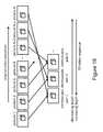
- FIG. 16illustrates an exemplary process for creating three-dimensional still images from a standard two-dimensional video sequence by identifying stereoscopic pairs in accordance with embodiments of the present invention
- FIG. 17illustrates an exemplary process for creating three-dimensional video from a standard two-dimensional video sequence according to embodiments of the present invention
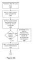
- FIG. 18illustrates an exemplary process of creating three-dimensional video with changing parallax and no translational motion from a standard two-dimensional video sequence in accordance with an embodiment of the subject matter disclosed herein;
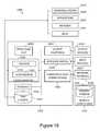
- FIG. 19illustrates an exemplary environment for implementing various aspects of the subject matter disclosed herein.
- the three-dimensional imagescan be viewed or displayed on a stereoscopic display.
- the three-dimensional imagesmay also be viewed or displayed on any other display capable of presenting three-dimensional images to a person using other suitable equipment, such as, but not limited to, three-dimensional glasses.
- the functions and methods described hereinmay be implemented on a device capable of capturing still images, displaying three-dimensional images, and executing computer executable instructions on a processor.
- the devicemay be, for example, a digital still camera, a video camera (or camcorder), a personal computer, a digital picture frame, a set-top box, an HDTV, a phone, or the like.
- Such devicesmay be capable of presenting three-dimensional images to a person without additional equipment, or if used in combination with other suitable equipment such as three-dimensional glasses.
- the functions of the devicemay include methods for rectifying and registering at least two images, matching the color and edges of the images, identifying moving objects, removing or adding moving objects from or to the images to equalize them, altering a perceived depth of objects, and any final display-specific transformation to create a single, high-quality three-dimensional image.
- the techniques described hereinmay be applied to still-captured images and video images, which can be thought of as a series of images; hence for the purpose of generalization the majority of the description herein is limited to still-captured image processing.
- any of the processes and steps described hereinmay be implemented in an automated fashion.
- any of the methods and techniques described hereinmay be automatically implemented without user input after the capture of a plurality of images.
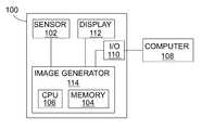
- FIG. 1illustrates a block diagram of an exemplary device 100 for creating three-dimensional images of a scene according to embodiments of the present invention.
- device 100is a digital camera capable of capturing several consecutive, still digital images of a scene.
- the device 100may be a video camera capable of capturing a video sequence including multiple still images of a scene.
- a user of the device 100may position the camera in different positions for capturing images of different perspective views of a scene.
- the captured imagesmay be suitably stored, analyzed and processed for creating three-dimensional images as described herein.
- the device 100may use the images for creating a three-dimensional image of the scene and for displaying the three-dimensional image to the user.
- the device 100may include a sensor array 102 of charge coupled device (CCD) or CMOS sensors which may be exposed to a scene through a lens and exposure control mechanism as understood by those of skill in the art.
- the device 100may also include analog and digital circuitry such as, but not limited to, a memory 104 for storing program instruction sequences that control the device 100 , together with a CPU 106 , in accordance with embodiments of the present invention.
- the CPU 106executes the program instruction sequences so as to cause the device 100 to expose the sensor array 102 to a scene and derive a digital image corresponding to the scene.
- the digital imagemay be stored in the memory 104 .
- All or a portion of the memory 104may be removable, so as to facilitate transfer of the digital image to other devices such as a computer 108 . Further, the device 100 may be provided with an input/output (I/O) interface 110 so as to facilitate transfer of digital image even if the memory 104 is not removable.
- the device 100may also include a display 112 controllable by the CPU 106 and operable to display the images for viewing by a user.
- the memory 104 and the CPU 106may be operable together to implement an image generator function 114 for creating three-dimensional images in accordance with embodiments of the present invention.
- the image generator function 114may generate a three-dimensional image of a scene using two or more images of the scene captured by the device 100 .
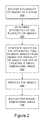
- FIG. 2illustrates a flow chart of an exemplary method for creating a three-dimensional image of a scene using the device 100 , alone or together with any other suitable device, in accordance with embodiments of the present invention. Referring to FIG. 2 , the method includes receiving 200 a plurality of images of a scene.
- a user of the device 100may use the input features of the device and move the device to different positions for capturing a plurality of images of a scene to which the sensor array 102 is exposed.
- the different imagescan include images of different perspective views of the scene.
- the CPU 106may then implement instructions stored in the memory 104 for storing the captured images in the memory 104 .
- the method of FIG. 2includes determining 202 attributes of the plurality of images.
- attributes of an image captured by an image capture devicemay include, but are not limited to, analysis of color(s), including mean, standard deviation, histogram correlation, cross correlation, edges, junctions, identified objects, size, orientation, and timestamps of images.
- the image generator function 114can determine one or more attributes. Additional exemplary details of determining attributes of images are provided herein.
- the method of FIG. 2also includes generating 204 , based on the attributes, two or more images from among the plurality of images for use in creating a three-dimensional image. For example, the image generator function 114 may compare the measured value of an attribute of one image to the measured value of an attribute of another image for determining a difference of the measured values. The image generator function 114 may then determine whether the difference meets a threshold value level. If the threshold criterion is met, the image generator function 114 determines that the images may be selected for use in creating a three-dimensional image. This process may be used for preliminarily and efficiently determining whether images are candidates for pairing as a three-dimensional image as described in further detail herein.
- the generated two or more imagesmay also be suitably processed 206 .
- the imagesmay be corrected and adjusted for display as described herein.
- the method of FIG. 2includes displaying 206 the three-dimensional image.
- the three-dimensional imagemay be displayed on the display 112 .
- the three-dimensional imagemay be communicated to and displayed on another device such as, but not limited to, a computer, video camera, digital picture frame, a set-top box, and a high-definition television.
- the above examplesare described for use with a device capable of capturing images, embodiments of the present invention described herein are not so limited.
- the methods described herein for creating a three-dimensional image of a scenemay for example be implemented in any suitable system including a memory and computer processor.
- the memorymay have stored therein computer-executable instructions.
- the computer processormay execute the computer-executable instructions.
- the memory and computer processormay be configured for implementing methods in accordance with embodiments of the present invention described herein.
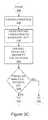
- FIGS. 3A-3Dillustrate a flow chart of an exemplary method for creating a three-dimensional image of a scene in accordance with embodiments of the present invention.
- the methodcan convert a plurality of images to a three-dimensional image that can be viewed on a stereoscopic display.
- the methodcan begin with receiving 300 a plurality of images of a scene.
- the imagescan be captured by a standard digital video or still camera, or a plurality of different cameras of the same type or different type.
- a camera usermay capture an initial image.
- the camera usermay capture subsequent image(s) at positions to the left or right of the position at which the initial image was captured.
- These imagesmay be captured as still images or as a video sequence of images.
- the imagesmay be captured using a device such as the device 100 shown in FIG. 1 .
- the imagesmay be stored in a memory such as the memory 104 shown in FIG. 1 .
- the imagesmay be received at a device after they have been captured by a different device.
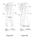
- FIG. 4Aillustrates a front view of a user 400 moving between positions for capturing different images using a camera 402 in accordance with embodiments of the present invention.
- the user 400is shown in solid lines in one position for capturing an image using the camera 402 .
- the user 400is shown in broken lines in another position for capturing another image using the camera 402 .
- the camera 402is also at different positions for capturing images offering different perspective views of a scene.
- the user 400stands with his or her feet separated by a desired binocular distance, then captures the first image while aligning the camera over his or her right foot (the position of the user 400 shown in solid lines). Then the user captures the second image, and possibly other images in between, while aligning the camera 402 over his or her left foot (the position of the user 400 shown in broken lines).
- the captured imagesmay be used for creating a three-dimensional image in accordance with embodiments of the present invention.
- FIG. 4Billustrates a front view of a user 410 moving between positions for capturing different images of a scene using a camera 412 in accordance with embodiments of the present invention.
- the user 410stands with his or her feet together and uses the camera 412 to capture the first image while maintaining a centered pose (the position of the user 410 shown in solid lines). Then the user moves one of his or her feet away from the other by twice the desired binocular distance while maintaining a centered pose and uses the camera 412 to capture the second image, and possibly other images in between (the position of the user 410 shown in broken lines).
- the captured imagesmay be used for creating a three-dimensional image in accordance with embodiments of the present invention.
- the distance between positions at which images are capturedcan affect the quality of the three-dimensional image.
- the optimal stereo baseline between the camera positionscan vary anywhere between 3 centimeters (cm) and several feet, dependent upon a variety of factors, including the distance of the closest objects in frame, the lens focal length or other optics properties of the camera, the camera crop factor (dependent on sensor size), the size and resolution of the display on which the images will be viewed, and the distance from the display at which viewers will view the images.
- a general recommendationis that the stereo baseline should not exceed the distance defined by the following equation:
- B12 ⁇ D 30 ⁇ ⁇ F ⁇ ⁇ C / 50 , where B is the stereo baseline separation in inches, D is the distance in feet to the nearest object in frame, F is the focal length of the lens in millimeters (mm), and C is the camera crop factor relative to a full frame (36 ⁇ 24 square mm.) digital sensor (which approximates the capture of a 35 mm analog camera).
- Bthe stereo baseline separation in inches
- Dthe distance in feet to the nearest object in frame
- Fthe focal length of the lens in millimeters (mm)
- Cis the camera crop factor relative to a full frame (36 ⁇ 24 square mm.) digital sensor (which approximates the capture of a 35 mm analog camera).
- the methodincludes selecting 302 two images among the plurality of captured images for use as a stereoscopic pair.
- the image generator function 114 shown in FIG. 1may be used for selecting captured images for use as a stereoscopic pair.
- One or more metricscan be defined for measuring one or more attributes of the plurality of images for selecting a stereoscopic pair. For example, a buffer of M consecutive images may be maintained, or stored in the memory 104 .
- the attributes of image with index mare compared with the corresponding attributes of image m+1. If there is no match between those two images, image m+1 is compared with image m+2. If images are determined to be sufficiently matched so as to be stereoscopic, and after those images have been processed as described below to generate a three-dimensional image, the m and m+2 images are compared to also identify a possible stereoscopic pair. The process may continue for all or a portion of the images in the buffer.
- FIG. 5illustrates a flow chart of an exemplary method for a preliminary, quick analysis to pre-screen whether an image pair may be a valid stereoscopic pair in accordance with embodiments of the present invention.
- the methodincludes defining 500 a candidate stereoscopic pair.
- the image generator function 114may define the image with index m and the image m+1 as a candidate stereoscopic pair.
- the method of FIG. 5includes performing 502 a series of measurements of the candidate stereoscopic image pair.
- the measurementsmay be of attributes of the image pair.
- the image generator function 114may measure or calculate the following values:
- the method of FIG. 5includes applying 504 criteria to the measurements.
- the image function generator 114 shown in FIG. 1may apply several criteria for determining if the images are a possible stereoscopic pair.
- Exemplary equations defining the application of these criteria to the image m and image m+1follow:
- ABS (MIN m ⁇ MIN m+1 )>ThresholdMIN ThresholdAV, ThresholdSAV, ThresholdMAX, and ThresholdMINare threshold value levels for the average, segmented average, maximum and minimum, respectively.
- the method of FIG. 5includes determining 506 whether any of the criteria are met.
- the image generator function 114may determine whether any of the criteria are met. If the differences between the values for each image are less than a defined threshold, analysis can continue using more complex techniques for determining whether the images are a suitable stereoscopic pair. For example, the method of FIGS. 6A-6C , described below, can be applied for determining whether the images are a suitable stereoscopic pair 508 . Otherwise, if all the differences are greater than the defined threshold, the images are rejected as a stereoscopic pair 510 .
- the methodincludes applying 304 rudimentary color adjustment to the images.
- the image generator function 114 shown in FIG. 1may apply color adjustment to the images.
- This optional color adjustmentcan be a normalized adjustment or DC-correction applied to a single image to allow luminance-based techniques to work better.
- several additional criteriamay typically be applied to the luminance planes (or optionally to all color planes), including, but not limited to, a Hough transform analysis 306 , segmentation 308 , edge detection 310 , and the like.
- segmented objects or blocks with high information contentcan be compared between the two image views using motion estimation techniques, based on differential error measures, such as, but not limited to, sum of absolute difference (SAD) or sum of squared errors (SSE), or correlation based measures, such as phase correlation or cross correlation.
- differential error measuressuch as, but not limited to, sum of absolute difference (SAD) or sum of squared errors (SSE)
- correlation based measuressuch as phase correlation or cross correlation.
- Rotational changes between the two imagesmay be considered and identified during this procedure.
- Segmented objects that are in one view onlyare indicative of occlusion, and having a significant number of occluded regions is indicative of a poor image pair for stereoscopy. Regions of occlusion identified during this process are recorded for use in later parts of the conversion process.
- motion vector displacement between matching objectsmay be recorded or stored for further use.
- vertical displacementcan be assessed.
- Vertical motion vector componentsare indicative of vertical parallax between the images, which when large can indicate a poor image pair.
- Vertical parallaxmust be corrected via rectification and registration to allow for comfortable viewing, and this correction will reduce the size of the overlapping region of the image in proportion to the original amount of vertical parallax.
- color datamay be compared to search for large changes between images. Such large changes can represent a color difference between the images regardless of similar luminance.
- FIGS. 3A-3Dincludes performing 312 edge-based analytics and matching for determining whether camera planes are parallel 313 .
- FIGS. 6A-6Cillustrate a flow chart of an exemplary method for edge-based analytics and matching for image correspondence, determination of right/left image, and camera toe-in/parallel plane configuration according to embodiments of the present invention.
- This methodmay be implemented by the image generator function 114 shown in FIG. 1 .
- two imagesare provided 600 .
- Edge detectionwhen applied to both images, can be the foundation for image analysis and correspondence.
- the image generator function 114 shown in FIG. 1may apply 602 numerous edge operators for this analysis.
- the edge operatorsmay include, but are not limited to, zero-cross or gradient-based operations.
- the image generator function 114may apply 604 a slice-based horizontal and vertical edge locator function for extracting edges from the binary images.
- the image generator function 114may also determine whether enough edges have been found 606 .
- This stage( 606 ) involves a comparison of the edges found from the two pictures to make sure that they meet a predefined minimum edge count. This stage also confirms the similarity of the two pictures by comparing the edge count of the two images to assure they are within a predefined percentage of each other. If enough edges have not been found, techniques alternative to edge-based processing techniques may be used 608 . These techniques include motion-estimation-based image matching and quadrant-based or full-image based cross correlation of the input images. Edge extensions from slice boundaries can be generated 610 if enough edges have been found.
- Block 614tests each edge to see if it intersects with a single image boundary (i.e., top, bottom, left or right boundary of image). In the event of an edge intersecting a single image boundary, block 616 classifies its primary point as the endpoint which is not on the boundary. Otherwise, block 618 classifies its primary point as the midpoint of the edge.
- Block 620involves solving a minimization problem via vertical edge matching in order to determine the optimal selection for the vertical shift between the two images. In an example for block 620 , the following equation may be used:
- Block 624then uses the calculated horizontal and vertical ⁇ 's to match each edge with its closest edge that meets the length, slope and curvature criteria.
- C i,j⁇ 0 otherwise 1 if P i matches Q j
- This matrixis then pruned in Box 626 so that no edge is matched with multiple other edges. In the event of multiple matches, the edge match with minimal distance is used.
- the edge matchesare broken down into regions of the image. The set of matching edges within each region are then characterized by the mean shift, and this mean shift is then the characteristic shift of the region. By examining the direction of the shifts of each subregion, it is thus possible to determine which picture is left and which is right. It is also possible to determine whether the second captured picture was captured with a focal axis parallel to the first picture. If not, there is some amount of toe-in or toe-out which can be characterized by the directional shifts of the subregions.
- the extracted edge sets from the two input imagescan be compared as part of a minimal optimization, in order to solve for the optimal delta translation between images.
- This ⁇ valueallows for determination of which image is left and right, as well as whether the cameras were in parallel configuration.
- the algorithmfrom FIGS. 3A-3D ) can proceed to the image registration without performing image rectification.
- FIG. 7is a graphical depiction of an edge detection example in accordance with embodiments of the present invention.
- the example of FIG. 7shows the edge detection map when edge detection is applied to a captured image, and demonstrates that the extracted images can be a representation of image composition.
- a Hough transformcan be applied 306 to identify lines in the two images of the potential stereoscopic pair. Lines that are non-horizontal, non-vertical, and hence indicate some perspective in the image can be compared between the two images to search for perspective changes between the two views that may indicate a perspective change or excessive toe-in during capture of the pair.
- the aforementioned criteriamay be applied to scaled versions of the original images for reducing computational requirements.
- the results of each measurementmay be gathered, weighted, and combined to make a final decision regarding the probable quality of a given image pair as a stereoscopic image pair.
- FIGS. 3A-3Dincludes identifying 314 a valid stereoscopic pair.
- FIGS. 8A and 8Billustrate a flow chart of an exemplary method for determining whether an image pair is a valid stereoscopic pair and which image is left and right according to embodiments of the present invention. This method may be implemented, for example, by the image generator function 114 shown in FIG. 1 .
- the methodincludes defining 800 a candidate stereoscopic image pair. In this example, two images with indices m and m+1 are examined.
- the methodincludes performing 802 a quick analysis to identify stereoscopic pairs.
- step 804color segmentation is performed on the objects.
- step 806the bounding box of 8 ⁇ 8 blocks for each object in each image may be identified.
- imagesmay be partitioned into N ⁇ N blocks.
- blocks with high information contentmay be selected.
- the methodincludes performing motion estimation on blocks in L relative to R image (accumulate motion vectors for L/R determination. These steps may be considered Techniques 1, 2, and 3.
- edge detectionmay be performed on left/right images.
- vertical and horizontal lines in left/right imagesmay be identified and may be classified by length, location, and slope.
- a Hough transformmay be performed on the left/right images.
- the methodincludes analyzing Hough line slope for left/right images and identifying non-vertical and non-horizontal lines.
- LDIAGrepresents the set of lines that have been identified as non-vertical or non-horizontal using the Hough transform.
- LHVrepresents lines that have been classified as either vertical or horizontal.
- MVYare the luminance motion vectors
- MVCRBthe chrominance motion vectors, for each segmented object or N ⁇ N block.
- MVYMis the mean luminance motion vector measurement
- MYCRBMthe mean chrominance motion vectors.
- BMADis the mean accumulated best match difference.
- ORGis the measurement of how well origins of horizontal/vertical lines match.
- LENis the measurement of how well lengths of horizontal/vertical lines match.
- SLPis the measurement of how well slopes of horizontal/vertical lines match.
- TINis the measurement of how well slopes of diagonal lines match.
- ⁇ MVYM⁇ i , j ⁇ MVY i , j , m , ⁇ ⁇
- ⁇ i ⁇ : ⁇ ⁇ object ⁇ ⁇ ID , j ⁇ : ⁇ ⁇ motion ⁇ ⁇ vector ⁇ ⁇ ID , m ⁇ : ⁇ ⁇ image ⁇ ⁇ ID ⁇ BMAD⁇ i ⁇ abs ⁇ [ block 0 , i , j , m - block m ⁇ ⁇ v , i , j , m + 1 ] , ⁇ where ⁇ ⁇ i ⁇ : ⁇ ⁇ object ⁇ ⁇ ID , j ⁇ : ⁇ ⁇ motion ⁇ ⁇ vector ⁇ ⁇ ID , m ⁇ : ⁇ ⁇ image ⁇ ⁇ ID , mv ⁇ : ⁇ ⁇ best ⁇ ⁇ match ⁇ ⁇ vector ⁇ ⁇ f ⁇
- a weighted average of the above measuresmay be performed to determine whether images are a pair or not.
- average motion vector directionmay be used to determine left/right images.
- the methodcan next include determining which image of the stereoscopic pair represents the left view image and which image represents the right view image.
- This aspectcan be important in many applications since, for example, a user can capture a plurality of images moving to the left or right.
- image segmentation 308can be performed to identify objects within the two captured views.
- the motion estimation stepthat has been defined before saves the motion vectors of each object or block with high information content. If the general motion of segmented objects is to the right for one view relative to the other, it is indicative of a left view image, and vice versa. Since the process of motion estimation of segmented objects is also used in stereoscopic pair evaluation, left/right image determination can be performed in parallel.
- the method of FIGS. 3A-3Dincludes rectification point selection 316 , rectification 318 , and region of interest identification 320 .
- interest points for stereo correspondence, rectification and registrationcan be identified.
- the left view image, sized N ⁇ Mis broken into a number, N, of smaller n ⁇ m sub-images.
- Each sub-imagecan be filtered to find junction points, or interest points, within and between objects in view.
- Interest pointscan be identified, for example, by performing horizontal and vertical edge detection, filtering for strong edges of a minimum length, and identifying crossing points of these edges.
- Interest point determinationcan be assisted by Hough transform line analysis when determining the dominant edges in a scene.
- Interest pointsmay not be selected from areas identified as occluded in the initial analysis of a stereo pair.
- Interest pointscan span the full image.
- rectification 318may be performed on the stereo pair of images.
- motion estimation techniquesas described in stereo pair identification above
- edge matching techniquesare applied to find the corresponding points in the right view image.
- FIG. 9depicts an example of applying this technique. Referring to FIG. 9 , the N corresponding points in the left and right view images are made into a 3 ⁇ N set of point values, for example:
- the camera epipolesare used with the interest point set to generate a pair of rectifying homographies. It can be assumed that the camera properties are consistent between the two captured images.
- the respective homographiesare then applied to the right and left images, creating the rectified images.
- the overlapping rectangular region of the two rectified imagesis then identified, the images are cropped to this rectangle, and the images are resized to their original dimensions, creating the rectified image pair, right_r and left_r.
- a set of interest pointsis required, and the interest point set selected for rectification (or a subset thereof) may be translated to positions relative to the output of the rectification process by applying the homography of the rectification step to the points.
- a second set of interest pointsmay be identified for the left_r image, and motion estimation and edge matching techniques may be applied to find the corresponding points in the right_r image.
- the interest point selection process for the registration operationis the same as that for rectification.
- the N corresponding interest pointsare made into a 3 ⁇ N set of point values as set forth in the following equations:
- the second set of interest points for the left_r imagemay be used to find correspondence in the Right′ image, the set of points as set forth in the following equations:
- the method of FIGS. 3A-3Dincludes an overall parallax, or disparity, calculation 332 .
- a pixel-by-pixel parallax, or disparity, mapis created for a stereoscopic pair of registered “Left′” and “Right′” images. This can be performed, for example, by using a hierarchical motion estimation operation between the Left′ and Right′ images, starting with blocks sized N ⁇ N and refining as necessary to smaller block sizes. During the estimation process, only horizontal displacement may be considered, limiting the search range.
- the methodincludes correspondence point selection 322 , correspondence 324 and registration transform to generate the Right′ image 326 .
- the methodincludes correspondence 328 and registration transform to generate the Left′ image 330 .
- FIG. 10illustrates a flow chart of an exemplary method for determining pixel disparities according to embodiments of the present invention.
- the methodmay be implemented, for example, by the image generator function 114 shown in FIG. 1 .
- the methodincludes receiving 1000 a transformed stereoscopic image pair, including a left and right image.
- the methodincludes dividing 1002 the images into blocks of N ⁇ N pixels. For every block, the method includes performing 1004 motion estimation between left and right to determine a best match vector. Next, for every pixel in each block, the method includes calculating 1006 the differences between left and right for the best match vector.
- the method of FIG. 10includes determining 1008 whether the best match difference is less than the threshold Tp. If the best match difference is less than the threshold Tp, the disparity of the pixel is set equal to the best match vector 1010 . Otherwise, if the best match difference is not less than the threshold Tp, the method includes determining 1012 whether the pixel is occluded. If the pixel is determined to be occluded, the disparity of the pixel is set equal to the best match vector 1010 . If the pixel is determined not to be occluded, the method includes grouping pixels in an M ⁇ M block and performing a new analysis with M ⁇ M refinement 1014 .
- the methodincludes determining 1016 whether there are more pixels in the current block being processed. If there are more pixels, the method returns to step 1006 . Otherwise, the method determines 1018 whether there are more blocks to be processed. If not, the method exits 1020 . If there are more blocks, the method returns to step 1004 .
- the methodincludes applying 334 a parallax analysis. For example, for a stereoscopic pair of registered “Left′” and “Right′” images, the maximum and minimum pixel parallax values can be analyzed to decide whether the maximum or minimum parallax is within the ability of a viewer to resolve a three-dimensional image. If it is determined that the parallax is within the ability of a viewer to resolve the three-dimensional image, the method proceeds to step 342 . If not, the method proceeds to step 336 . Occluded regions and pixels with “infinite” parallax are not considered in this exemplary method.
- the screen plane of the stereoscopic imagecan be altered 336 , or relocated, to account for disparities measured as greater than a viewer can resolve. This is performed by scaling the translational portion of transforms that created the registered image views by a percent offset and re-applying the transforms to the original images. For example, if the initial left image transform is as follows:
- Tl⁇ S * cos ⁇ ⁇ ⁇ S * sin ⁇ ⁇ ⁇ Tx - S * sin ⁇ ⁇ ⁇ S * cos ⁇ ⁇ ⁇ Ty 0 0 1 ⁇ for scaling factor S, X/Y rotation angle ⁇ , and translational offsets Tx and Ty, the adjustment transform becomes
- Tl alt⁇ S * cos ⁇ ⁇ ⁇ S * sin ⁇ ⁇ ⁇ Tx * Xscale - S * sin ⁇ ⁇ ⁇ S * cos ⁇ ⁇ ⁇ Ty * Yscale 0 0 1 ⁇
- Xscale and Yscaleare determined by the desired pixel adjustment relative to the initial transform adjustment, i.e.,
- Xscale1 + ( desired_pixel ⁇ _adjustment ) Tx . Only in rare occurrences will Yscale be other than zero, and only then as a corrective measure for any noted vertical parallax.
- Such scalingeffectively adds to or subtracts from the parallax for each pixel, effectively moving the point of now parallax forward or backward in the scene.
- the appropriate scalingis determined by the translational portion of the transform and the required adjustment.
- step 338 of FIGS. 3A-3Dit is determined whether the parallax is within the ability of a viewer to resolve the three-dimensional image. If it is determined that the parallax is within the ability of a viewer to resolve the three-dimensional image, the method proceeds to step 342 . If not, the method proceeds to step 340 .
- the pixel-by-pixel parallax for pixels of segmented objectsmay also be adjusted 340 , or altered, which effectively performs a pseudo-decrease (or increase) in the parallax of individual segmented objects for objects that still cannot be resolved after the screen adjustments above. This process involves the same type of manipulation and re-application of a transform, but specific to a given region of the picture, corresponding to the objects in question.
- FIG. 11illustrates a flow chart of an exemplary method for adjusting parallax of segmented, moving objects according to embodiments of the present invention.
- FIG. 12illustrates an exemplary diagram of a method for adjusting parallax of moving, segmented objects according to embodiments of the present invention.
- the methodmay be implemented, for example, by the image generator function 114 shown in FIG. 1 .
- the methodincludes identifying 1100 a segmented object in an image I to relocate.
- the method of FIG. 11also includes defining a bounding rectangle R around the object and defining left/right bounds of a region M for left/right motion 1102 .
- multiple rectangular regionsmay need to be defined and moved, but the process executes identically for each region.
- the scaled version of the registration transform matrix T altis provided 1104 .
- the inverse of the altered transform(assumed already calculated as above for movement of the screen plane for the whole image) may then be applied 1106 to the opposite edge of the region R to get the other edge of region M.
- the movement of Ris intended to be to the right, and that the left image is to be altered (meaning Tl alt has been created for the intended movement).
- Pis an extra number of pixels for blending
- Tl alt ⁇ 1is the inverse transform of Tl alt . Note that P is added after the transform application, and only to the X coordinates.
- the region to be movedis now defined as the pixels within the rectangle defined by M.
- the method of FIG. 11includes overwriting 1110 pixels within the defined rectangle in the transformed image with the newly transformed pixels.
- the method of FIG. 11includes interpolating the outer P pixels on each side of the area with existing data.
- the area in Left′ defined by the coordinates M ul , M ll , R ur , and R lrwill be empty, but is filled with a linear gradient fill between points on each horizontal line in the region.
- the interpolationis always performed on a power of two, meaning that the interpolation will produce one of 1, 2, 4, 8, 16, etc.
- Pixel regions that are not a power of twoare mapped to the closest power of two, and either pixel repetition or truncation of the sequence is applied to fit.
- a weighted averaging the outer P “extra” pixels on each side of the rectangle with the pixel data currently in those positionsis performed to blend the edges.
- the disparity map calculated using the two views, “Left′” and “Right′,”can be altered for the region M to reduce the disparity values in that region, and then applied to one of the “Left′” or “Right′” single image views to create a new view (e.g., “Left_disparity”).
- the result of this processis a new stereo pair (e.g., “Left′” and “Left_disparity”) that recreates the depth of the original pair, but with lesser parallax for the objects within the region M.
- the “disparity” viewbecomes the new opposite image to the original, or for example, a created “Left_disparity” image becomes the new “Right′” image.
- the methodincludes performing 342 depth enhancements.
- the screen plane of the stereoscopic imagemay be relocated to allow a viewer to emphasize or de-emphasize object depth in the three-dimensional image. This relocation may be implemented to enhance the subjective quality of the displayed image or to create three-dimensional effects that involve changing object depth over time to simulate motion.
- the process for thisuses the same procedures as for general readjustment of the screen plane, and for segmented object specific adjustments, but is performed voluntarily for effect, rather than necessarily for correction.
- the method of FIGS. 3A-3Dincludes removing 344 moving objects. For example, for a stereoscopic pair of registered “Left′” and “Right′” images, disparity differences can be identified which indicate object motion within, into, or out of the image frame for one image. These areas can be identifiable as those which have “infinite” parallax assignments from the disparity map step of the process. Areas indicating such motion are replicated or removed using data from the other image view and/or other views captured between the “Left” and “Right” images. Without any loss of generality, we will assume that first picture taken is the leftmost, and the last picture taken is the rightmost. In actuality, the opposite can occur. In the following description the following definitions apply:
- the actual object removal processinvolves identifying N ⁇ N blocks, with N empirically determined, to make up a bounding region for the region of “infinite” parallax, plus an additional P pixels (for blending purposes), determining the corresponding position of those blocks in the other images using the parallax values of the surrounding P pixels that have a similar gradient value (meaning that high gradient areas are extrapolated from similar edge areas and low gradient areas are extrapolated from similar surrounding flat areas), copying the blocks/pixels from the opposite locations to the intended new location, and performing a weighted averaging of the outer P “extra” pixels with the pixel data currently in those positions to blend the edges. If it is determined to remove an object, fill-in data is generated 346 . Otherwise, the method proceeds to step 348 .
- FIGS. 13A , 13 B, and 13 Cillustrate an exemplary process for disparity interpolation according to embodiments of the present invention.
- positions 1300 and 1302are positions of a camera (not shown) when capturing images of object 1304 at different times.
- the image captured at position 1300was captured prior to the image captured at position 1302 .
- a view of the object 1304 from position 1300is indicated by lines 1306
- a view of the object 1304 from position 1302is indicated by lines 1308 .
- the object 1304is moving from left to right across the camera's view. Between the image capture times, the object 1304 has moved from a position 1304 A (shown in a broken line) to the position 1304 shown in FIG. 13B ) as shown in FIG. 13B .
- the movement of the object 1304is such that the disparity is unacceptable and should be corrected.
- the image obtained from position 1300can be utilized for creating a three-dimensional image, and the image obtained from position 1302 can be altered for use together with the other image in creating the three-dimensional image.
- the object 1304may be moved to the left (as indicated by direction arrow 1312 in FIG. 13C ) in the image captured from position 1302 .
- the object 1304may be moved to the left to a position of a desired left view (i.e., the positioning of the object 1304 within the view from position 1302 as indicated by lines 1314 shown in FIG. 13C .
- the desired left image for the three-dimensional imagemay be composed by reducing visibility of the left-most pixel from RLa to RLd; and by increasing visibility of the right-most pixel by interpolating the [RRd, RRa] area from pixels found in the right-most of RRa.
- FIG. 14illustrates a flow chart of an exemplary method for adding/removing objects from a single image according to embodiments of the present invention.
- the methodincludes creating parallax maps for stereoscopic images I 1 and I 2 and defining the area of image I 1 to change (step 1400 ).
- the method of FIG. 13also includes defining 1402 8 ⁇ 8 blocks in image I 1 to cover the intended area plus P pixels.
- the corresponding data in image I 2is found (step 1404 ).
- the corresponding datais copied from image I 2 to image I 1 (step 1406 ).
- the methodincludes applying a weighted average of the outer P pixels of the copy (step 1408 ).
- FIG. 15the figure is a diagram of an exemplary method for adding/removing objects from a single image according to embodiments of the present invention.
- An original “Left′” image 1500 and an original “Right′” image 1502are provided.
- the imagesmay be paired to form a three-dimensional image in accordance with embodiments of the present invention described herein.
- the images 1500 and 1502both show objects, which are designated 1504 L and 1506 L, respectively, in the “Left′” image 1500 , and designated 1504 R and 1506 R, respectively, in the “Right′” image 1502 .
- the parallax of these objectsis such that three-dimensional display of these objects in the three-dimensional image 1504 would be satisfactory to a viewer.
- the images of another object(designated 1508 L in the “Left′” image 1500 , and designated 1508 R in the “Right′” image 1502 ) were captured while the object was moving at such a speed such that the parallax disparity of the object in the “Left′” image 1500 and the “Right′” image 1502 makes viewing the three-dimensional image 1504 of the object unsatisfactory to a viewer. For this reason, the moving object may be removed from the “Left′” image 1500 and the “Right′” image 1502 .
- a new “Left′” image 1510 without the moving objectmay be generated by bounding a region 1512 L to be corrected in the original “Left′” image 1500 for removing the moving object (i.e., an area including the moving object in the “Left′” image 1500 ).
- a corresponding area in the original “Right′” image 1502may be copied and used for replacing the bounded region 1512 L in the original “Left′” image 1500 to render the new “Left′” image 1510 .
- a new “Right′” image 1514 without the moving objectcan be rendered.
- the new “Left′” image 1510 and the new “Right′” image 1514can then be paired for rendering a new three-dimensional image 1516 without the moving object.
- the disparity map calculated using multiple views, “Left”, “Right”, and/or the images in betweencan be applied to one of the “Left” or “Right” single image views to create a new view (e.g., “Left_disparity”).
- the result of this processis a new stereo pair (e.g., “Left′” and “Left_disparity”) that effectively recreates the depth of the original pair, but without object occlusions, movement, additions, or removals.
- the “disparity” viewbecomes the new opposite image to the original, or for example, a created “Left_disparity” image becomes the new “Right′” image. Effectively, this procedure mimics segmented object removal and/or addition, but on a full image scale.
- the methodincludes applying 348 color correction to the images. For example, for a plurality of images, a pixel-by-pixel color comparison may be performed to correct lighting changes between image captures. This is performed by using the parallax map to match pixels from Left′ to Right′ and comparing the luminance and chrominance values of those pixels. Pixels with both large luminance and chrominance discrepancies are ignored, assuming occlusion. Pixels with similar luminance and variable chrominance are altered to average their chrominance levels to be the same. Pixels with similar chrominance and variable luminance are altered to average their luminance values to account for lighting and reflection changes.
- the “Left′” and “Right′” imagesare ordered and rendered to a display as a stereoscopic image.
- the formatis based on the display parameters. Rendering can require interlacing, anamorphic compression, pixel alternating, and the like.
- the “Left′” viewmay be compressed as the base image and the “Right′” image may be compressed as the disparity difference from the “Left′” using a standard video codec, differential JPEG, or the like.
- the method of FIGS. 3A-3Dincludes displaying 350 the three-dimensional image on a stereoscopic display.
- the three-dimensional imagemay be displayed on the display 112 of the device 100 or a display of the computer 108 .
- the three-dimensional imagemay be suitably communicated to another device for display.
- stereoscopic pairscan be found within the sequence of resulting images. Stereoscopic pairs are identified based on their distance from one another determined by motion analysis (e.g., motion estimation techniques). Each pair represents a three-dimensional picture or image, which can be viewed on a suitable stereoscopic display. If the camera does not have a stereoscopic display, the video sequence can be analyzed and processed on any suitable display device. If the video sequence is suitable for creating three-dimensional content (e.g., one or more three-dimensional images), it is likely that there are many potential stereoscopic pairs, as an image captured at a given position may form a pair with images captured at several other positions. The image pairs can be used to create three-dimensional still images or re-sequenced to create a three-dimensional video.
- motion analysise.g., motion estimation techniques
- FIG. 15illustrates an exemplary process for creating three-dimensional still images from a standard two-dimensional video sequence by identifying stereoscopic pairs in accordance with embodiments of the present invention.
- this processcan be used to create content for multi-view stereoscopic displays by creating a set of three-dimensional images of a subject with the same parallax but captured from slightly different positions.
- a three-dimensional video sequencecan be created using one of the following methods. The first method is to select stereoscopic pairs with a constant positional offset, and sequence them in the same relative order in which they were captured.
- FIG. 17illustrates an exemplary process for creating three-dimensional video from a standard two-dimensional video sequence according to embodiments of the present invention.
- Another method of creating a three-dimensional sequenceincludes creating stereoscopic pairs by grouping the first and last images in the sequence, followed by the second and next-to-last images, and so on until all images have been used. During playback this creates the effect of the camera remaining still while the depth of the scene decreases over time due to decreasing parallax.
- the three-dimensional imagescan also be sequenced in the opposite order so that the depth of the scene increases over time.
- FIG. 18illustrates an exemplary process of creating three-dimensional video with changing parallax and no translational motion from a standard two-dimensional video sequence in accordance with an embodiment of the subject matter disclosed herein.
- the camera or other display devicecan store a representation of the resulting three-dimensional still images or video in an appropriate compressed format.
- one of the images in the stereoscopic paircan be compressed directly, while the other image is represented by its differences with the first image.
- the first stereoscopic pair in the sequencecan be stored as described above for still images, while all images in other pairs are represented by their differences with the first image.
- the generation and presentation, such as display, of three-dimensional images of a scene in accordance with embodiments of the present inventionmay be implemented by a single device or combination of devices.
- imagesmay be captured by a camera such as, but not limited to, a digital camera.
- the cameramay be connected to a personal computer for communication of the captured images to the personal computer.
- the personal computermay then generate one or more three-dimensional images in accordance with embodiments of the present invention.
- the personal computermay communicate the three-dimensional images to the camera for display on a suitable three-dimensional display.
- the cameramay include a suitable three-dimensional display.
- the cameramay be in suitable electronic communication with a high-definition television for display of the three-dimensional images on the television.
- the communication of the three-dimensional imagesmay be, for example, via an HDMI connection.
- three-dimensional imagesmay be generated by a camera and displayed by a separate suitable display.
- the cameramay capture conventional two-dimensional images and then use the captured images to generate three-dimensional images.
- the cameramay be in suitable electronic communication with a high-definition television for display of the three-dimensional images on the television.
- the communication of the three-dimensional imagesmay be, for example, via an HDMI connection.
- FIG. 19 and the following discussionare intended to provide a brief, general description of a suitable operating environment 1900 in which various aspects of the disclosed subject matter may be implemented. While the invention is described in the general context of computer-executable instructions, such as program modules, executed by one or more computers or other devices, those skilled in the art will recognize that the disclosed subject matter can also be implemented in combination with other program modules and/or as a combination of hardware and software.
- program modulesinclude routines, programs, objects, components, data structures, etc. that perform particular tasks or implement particular data types.
- the operating environment 1800is only one example of a suitable operating environment and is not intended to suggest any limitation as to the scope of use or functionality of the subject matter disclosed herein.
- Other well known computer systems, environments, and/or configurationsthat may be suitable for use with the invention include but are not limited to, personal computers, hand-held or laptop devices, multiprocessor systems, microprocessor-based systems, programmable consumer electronics, network PCs, minicomputers, mainframe computers, distributed computing environments that include the above systems or devices, and the like.
- an exemplary environment 1900 for implementing various aspects of the subject matter disclosed hereinincludes a computer 1902 .
- the computer 1902includes a processing unit 1904 , a system memory 1906 , and a system bus 1908 .
- the system bus 1908couples system components including, but not limited to, the system memory 1906 to the processing unit 1904 .
- the processing unit 1904can be any of various available processors. Dual microprocessors and other multiprocessor architectures also can be employed as the processing unit 1904 .
- the system bus 1908can be any of several types of bus structure(s) including the memory bus or memory controller, a peripheral bus or external bus, and/or a local bus using any variety of available bus architectures including, but not limited to, 11-bit bus, Industrial Standard Architecture (ISA), Micro-Channel Architecture (MCA), Extended ISA (EISA), Intelligent Drive Electronics (IDE), VESA Local Bus (VLB), Peripheral Component Interconnect (PCI), Universal Serial Bus (USB), Advanced Graphics Port (AGP), Personal Computer Memory Card International Association bus (PCMCIA), and Small Computer Systems Interface (SCSI).
- ISAIndustrial Standard Architecture
- MCAMicro-Channel Architecture
- EISAExtended ISA
- IDEIntelligent Drive Electronics
- VLBVESA Local Bus
- PCIPeripheral Component Interconnect
- USBUniversal Serial Bus
- AGPAdvanced Graphics Port
- PCMCIAPersonal Computer Memory Card International Association bus
- SCSISmall Computer Systems Interface
- the system memory 1906includes volatile memory 1910 and nonvolatile memory 1912 .
- the basic input/output system (BIOS)containing the basic routines to transfer information between elements within the computer 1902 , such as during start-up, is stored in nonvolatile memory 1912 .
- nonvolatile memory 1912can include read only memory (ROM), programmable ROM (PROM), electrically programmable ROM (EPROM), electrically erasable ROM (EEPROM), or flash memory.
- Volatile memory 1910includes random access memory (RAM), which acts as external cache memory.
- RAMis available in many forms such as synchronous RAM (SRAM), dynamic RAM (DRAM), synchronous DRAM (SDRAM), double data rate SDRAM (DDR SDRAM), enhanced SDRAM (ESDRAM), Synchlink DRAM (SLDRAM), and direct Rambus RAM (DRRAM).
- SRAMsynchronous RAM
- DRAMdynamic RAM
- SDRAMsynchronous DRAM
- DDR SDRAMdouble data rate SDRAM
- ESDRAMenhanced SDRAM
- SLDRAMSynchlink DRAM
- DRRAMdirect Rambus RAM
- Computer 1902also includes removable/nonremovable, volatile/nonvolatile computer storage media.
- FIG. 19illustrates, for example, disk storage 1914 .
- Disk storage 1914includes, but is not limited to, devices like a magnetic disk drive, floppy disk drive, tape drive, Jaz drive, Zip drive, LS-100 drive, flash memory card, or memory stick.
- disk storage 1024can include storage media separately or in combination with other storage media including, but not limited to, an optical disk drive such as a compact disk ROM device (CD-ROM), CD recordable drive (CD-R Drive), CD rewritable drive (CD-RW Drive) or a digital versatile disk ROM drive (DVD-ROM).
- CD-ROMcompact disk ROM device
- CD-R DriveCD recordable drive
- CD-RW DriveCD rewritable drive
- DVD-ROMdigital versatile disk ROM drive
- a removable or non-removable interfaceis typically used such as interface 1916 .
- FIG. 19describes software that acts as an intermediary between users and the basic computer resources described in suitable operating environment 1900 .
- Such softwareincludes an operating system 1918 .
- Operating system 1918which can be stored on disk storage 1914 , acts to control and allocate resources of the computer system 1902 .
- System applications 1920take advantage of the management of resources by operating system 1918 through program modules 1922 and program data 1924 stored either in system memory 1906 or on disk storage 1914 . It is to be appreciated that the subject matter disclosed herein can be implemented with various operating systems or combinations of operating systems.
- a userenters commands or information into the computer 1902 through input device(s) 1926 .
- Input devices 1926include, but are not limited to, a pointing device such as a mouse, trackball, stylus, touch pad, keyboard, microphone, joystick, game pad, satellite dish, scanner, TV tuner card, digital camera, digital video camera, web camera, and the like.
- These and other input devicesconnect to the processing unit 1904 through the system bus 1908 via interface port(s) 1928 .
- Interface port(s) 1928include, for example, a serial port, a parallel port, a game port, and a universal serial bus (USB).
- Output device(s) 1930use some of the same type of ports as input device(s) 1926 .
- a USB portmay be used to provide input to computer 1902 and to output information from computer 1902 to an output device 1930 .
- Output adapter 1932is provided to illustrate that there are some output devices 1930 like monitors, speakers, and printers among other output devices 1930 that require special adapters.
- the output adapters 1932include, by way of illustration and not limitation, video and sound cards that provide a means of connection between the output device 1930 and the system bus 1908 . It should be noted that other devices and/or systems of devices provide both input and output capabilities such as remote computer(s) 1934 .
- Computer 1902can operate in a networked environment using logical connections to one or more remote computers, such as remote computer(s) 1934 .
- the remote computer(s) 1934can be a personal computer, a server, a router, a network PC, a workstation, a microprocessor based appliance, a peer device or other common network node and the like, and typically includes many or all of the elements described relative to computer 1902 .
- only a memory storage device 1936is illustrated with remote computer(s) 1934 .
- Remote computer(s) 1934is logically connected to computer 1902 through a network interface 1938 and then physically connected via communication connection 1940 .
- Network interface 1938encompasses communication networks such as local-area networks (LAN) and wide-area networks (WAN).
- LAN technologiesinclude Fiber Distributed Data Interface (FDDI), Copper Distributed Data Interface (CDDI), Ethernet/IEEE 1102.3, Token Ring/IEEE 1102.5 and the like.
- WAN technologiesinclude, but are not limited to, point-to-point links, circuit switching networks like Integrated Services Digital Networks (ISDN) and variations thereon, packet switching networks, and Digital Subscriber Lines (DSL).
- ISDNIntegrated Services Digital Networks
- DSLDigital Subscriber Lines
- Communication connection(s) 1940refers to the hardware/software employed to connect the network interface 1938 to the bus 1908 . While communication connection 1940 is shown for illustrative clarity inside computer 1902 , it can also be external to computer 1902 .
- the hardware/software necessary for connection to the network interface 1938includes, for exemplary purposes only, internal and external technologies such as, modems including regular telephone grade modems, cable modems and DSL modems, ISDN adapters, and Ethernet cards.
- the various techniques described hereinmay be implemented with hardware or software or, where appropriate, with a combination of both.
- the methods and apparatus of the disclosed embodiments, or certain aspects or portions thereofmay take the form of program code (i.e., instructions) embodied in tangible media, such as floppy diskettes, CD-ROMs, hard drives, or any other machine-readable storage medium, wherein, when the program code is loaded into and executed by a machine, such as a computer, the machine becomes an apparatus for practicing the invention.
- the computerwill generally include a processor, a storage medium readable by the processor (including volatile and non-volatile memory and/or storage elements), at least one input device and at least one output device.
- One or more programsare preferably implemented in a high level procedural or object oriented programming language to communicate with a computer system.
- the program(s)can be implemented in assembly or machine language, if desired.
- the languagemay be a compiled or interpreted language, and combined with hardware implementations.
- the described methods and apparatusmay also be embodied in the form of program code that is transmitted over some transmission medium, such as over electrical wiring or cabling, through fiber optics, or via any other form of transmission, wherein, when the program code is received and loaded into and executed by a machine, such as an EPROM, a gate array, a programmable logic device (PLD), a client computer, a video recorder or the like, the machine becomes an apparatus for practicing the invention.
- a machinesuch as an EPROM, a gate array, a programmable logic device (PLD), a client computer, a video recorder or the like
- PLDprogrammable logic device
- client computera client computer
- video recorderor the like
- the program codeWhen implemented on a general-purpose processor, the program code combines with the processor to provide a unique apparatus that operates to perform the processing of the present invention.
Landscapes
- Engineering & Computer Science (AREA)
- Multimedia (AREA)
- Signal Processing (AREA)
- Physics & Mathematics (AREA)
- General Physics & Mathematics (AREA)
- Testing, Inspecting, Measuring Of Stereoscopic Televisions And Televisions (AREA)
Abstract
Description
where B is the stereo baseline separation in inches, D is the distance in feet to the nearest object in frame, F is the focal length of the lens in millimeters (mm), and C is the camera crop factor relative to a full frame (36×24 square mm.) digital sensor (which approximates the capture of a 35 mm analog camera). In the examples provided herein, it is assumed that at least two images have been captured, at least two of which can be interpreted as a stereoscopic pair.
- Average image value
- Segmented average image value: Divide image in k segments and take the average of those segments
- Minimum pixel value for each color of the image (MIN)
- Maximum pixel value for each color of the image (MAX)
Image pair is not stereoscopic=ABS(AVm−AVm+1)>ThresholdAV
OR
For allk, ABS(SAVk,m−SAVk,m−1)>ThresholdSAV
OR
ABS(MAXm−MAXm+1)>ThresholdMAX
OR
ABS(MINm−MINm+1)>ThresholdMIN
ThresholdAV, ThresholdSAV, ThresholdMAX, and ThresholdMIN are threshold value levels for the average, segmented average, maximum and minimum, respectively. These equations can be applied to all or at least some of the colors.
For each vertical edge in one image, determine the closest edge in the other image, subject to meeting criteria for length, slope and curvature. For distance, use the distance between the primary points. If this distance is larger than ε, it is deemed that no edge matches, and this edge contributes ε to the cost function. The end result of the optimization is the determination of δ, the optimal shift between the two images based on this vertical edge matching. In
Ci,j={0 otherwise1 if P
The output of this stage is the matrix C, which has 1 in location i,j if edge i and j are matching edges and otherwise 0. This matrix is then pruned in
and the fundamental matrix equation
rightptsT*F*leftpts=0
is solved or approximated to determine the 3×3 fundamental matrix, F, and epipoles, e1 and e2. The camera epipoles are used with the interest point set to generate a pair of rectifying homographies. It can be assumed that the camera properties are consistent between the two captured images. The respective homographies are then applied to the right and left images, creating the rectified images. The overlapping rectangular region of the two rectified images is then identified, the images are cropped to this rectangle, and the images are resized to their original dimensions, creating the rectified image pair, right_r and left_r. The rectified image pair can be defined by the following equations:
right—r=cropped(F*right)
left—r=cropped(F*left)
For the stereo pair of “left_r” and “right_r” images, registration is next performed on the stereo pair. A set of interest points is required, and the interest point set selected for rectification (or a subset thereof) may be translated to positions relative to the output of the rectification process by applying the homography of the rectification step to the points. Optionally, a second set of interest points may be identified for the left_r image, and motion estimation and edge matching techniques may be applied to find the corresponding points in the right_r image. The interest point selection process for the registration operation is the same as that for rectification. Again, the N corresponding interest points are made into a 3×N set of point values as set forth in the following equations:
and the following matrix equation
left—rpts=Tr*right—rpts
is approximated for a 3×3 linear conformal transformation, Tr, which may incorporate both translation on the X and Y axes and rotation in the X/Y plane. The transform Tr is applied to the right_r image to create the image “Right′” as defined by the following equation:
Right′=Tr*right—r,
where right_r is organized as a 3×N set of points (xir, yir, 1) for i=1 to image_rows*image cols.
is identified and composed, and the equation
Right′pts=Tl*left—rpts
is approximated for a second linear conformal transformation, Tl. The transform Tl is applied to the left_r image to create the image “Left′”, as defined by the following equation:
Left′=Tl*left—r
“Right′” and “Left′” images represent a rectified, registered stereoscopic pair.
for scaling factor S, X/Y rotation angle θ, and translational offsets Tx and Ty, the adjustment transform becomes
where Xscale and Yscale are determined by the desired pixel adjustment relative to the initial transform adjustment, i.e.,
Only in rare occurrences will Yscale be other than zero, and only then as a corrective measure for any noted vertical parallax. Using the altered transform, a new registered image view is created, e.g. the following:
Left′=Tlalt*left—r
Such scaling effectively adds to or subtracts from the parallax for each pixel, effectively moving the point of now parallax forward or backward in the scene. The appropriate scaling is determined by the translational portion of the transform and the required adjustment.
Rul=(xl,yu); the upper left coordinate
Rll=(xl,yl); the lower left coordinate
Rur=(xr,yu); the upper right coordinate
Rlr=(xr,yl); the lower right coordinate
For a large or complex object, multiple rectangular regions may need to be defined and moved, but the process executes identically for each region.
Mur=(xr+P,yu); upper right
Mlr=(xr+P,yl); lower right
If movement is to the left, the left bounding edge of region M is defined as:
Mul=(xl−P,yu); upper left
Mll=(xl−P,yl); lower left
P is an extra number of pixels for blending purposes. The scaled version of the registration transform matrix Taltis provided1104. The inverse of the altered transform (assumed already calculated as above for movement of the screen plane for the whole image) may then be applied1106 to the opposite edge of the region R to get the other edge of region M. For the sake of example, assume that the movement of R is intended to be to the right, and that the left image is to be altered (meaning Tlalthas been created for the intended movement). Since the right side of M is already known, the other side can now be determined as:
Mul=Tlalt−1*Rul+(P,0); upper right
Mll=Tlalt−1*Ru+(P,0); lower right
Again, P is an extra number of pixels for blending, and Tlalt−1is the inverse transform of Tlalt. Note that P is added after the transform application, and only to the X coordinates. The region to be moved is now defined as the pixels within the rectangle defined by M.
Left′=Tlalt*left—r,for the left—rregion defined byRul, Rll, Mur, andMlr.
The method of
d=Rul(x)−Mul(x)
for the x-coordinates of Ruland Mul, and then proceeds to determine an interpolated gradient between the two pixel positions to fill in the missing values. For simplicity of implementation, the interpolation is always performed on a power of two, meaning that the interpolation will produce one of 1, 2, 4, 8, 16, etc. pixels as needed between the two defined pixels. Pixel regions that are not a power of two are mapped to the closest power of two, and either pixel repetition or truncation of the sequence is applied to fit. As an example, if Rul(x)=13 and Mul(x)=6, then d=7, and the following intermediate pixel gradient is calculated for a given row, j, in the region:
Since only 7 values are needed, p8 would go unused in this case, such that the following assignments would be made:
(x6,yj)=p1
(x7,yj)=p2
(x8,yj)=p3
(x9,yj)=p4
(x10,yj)=p5
(x11,yj)=p6
(x12,yj)=p7.
This process can repeat for each row in the empty region.
- First picture: the first picture captured in the sequence (1)
- Last picture: the last picture captured in the sequence (N)
- Leftmost pictures: any set of pictures from 1stto N−1
- Rightmost pictures: any set of pictures from 2ndto Nth
- Left target picture: any of the leftmost pictures or a modified version of all captured pictures that will be used during the 3D generation process as left picture
- Right target picture: any of the rightmost pictures or a modified picture that will be used during the 3D generation process as right picture
The method of identifying and compensating for moving objects consists of the following steps. For a given sequence of pictures captured between two positions, divide each picture into smaller areas and calculate motion vectors between all pictures in all areas. Calculate by a windowed moving average the global motion that results from the panning of the camera. Then subtract the area motion vector from the global motion to identify the relative motion vectors of each area in each picture. If the motion of each area is below a certain threshold, the picture is static and the first and last picture, or any other set with the desired binocular distance, can be used as left and right target pictures to form a valid stereoscopic pair that will be used for registration, rectification, and generation of a 3D picture. If the motion of any area is above an empirical threshold, then identify all other areas that have zero motion vectors and copy those areas from any of the leftmost pictures to the target left picture and any of the rightmost pictures to the target right picture.
Claims (28)
Priority Applications (5)
| Application Number | Priority Date | Filing Date | Title |
|---|---|---|---|
| US12/842,084US8508580B2 (en) | 2009-07-31 | 2010-07-23 | Methods, systems, and computer-readable storage media for creating three-dimensional (3D) images of a scene |
| US13/115,459US9380292B2 (en) | 2009-07-31 | 2011-05-25 | Methods, systems, and computer-readable storage media for generating three-dimensional (3D) images of a scene |
| US15/193,623US10080012B2 (en) | 2009-07-31 | 2016-06-27 | Methods, systems, and computer-readable storage media for generating three-dimensional (3D) images of a scene |
| US16/129,273US11044458B2 (en) | 2009-07-31 | 2018-09-12 | Methods, systems, and computer-readable storage media for generating three-dimensional (3D) images of a scene |
| US17/351,609US12034906B2 (en) | 2009-07-31 | 2021-06-18 | Methods, systems, and computer-readable storage media for generating three-dimensional (3D) images of a scene |
Applications Claiming Priority (2)
| Application Number | Priority Date | Filing Date | Title |
|---|---|---|---|
| US23013109P | 2009-07-31 | 2009-07-31 | |
| US12/842,084US8508580B2 (en) | 2009-07-31 | 2010-07-23 | Methods, systems, and computer-readable storage media for creating three-dimensional (3D) images of a scene |
Related Parent Applications (2)
| Application Number | Title | Priority Date | Filing Date |
|---|---|---|---|
| US12/842,171Continuation-In-PartUS8436893B2 (en) | 2009-07-31 | 2010-07-23 | Methods, systems, and computer-readable storage media for selecting image capture positions to generate three-dimensional (3D) images |
| US12/842,171ContinuationUS8436893B2 (en) | 2009-07-31 | 2010-07-23 | Methods, systems, and computer-readable storage media for selecting image capture positions to generate three-dimensional (3D) images |
Related Child Applications (1)
| Application Number | Title | Priority Date | Filing Date |
|---|---|---|---|
| US13/115,459Continuation-In-PartUS9380292B2 (en) | 2009-07-31 | 2011-05-25 | Methods, systems, and computer-readable storage media for generating three-dimensional (3D) images of a scene |
Publications (2)
| Publication Number | Publication Date |
|---|---|
| US20110025825A1 US20110025825A1 (en) | 2011-02-03 |
| US8508580B2true US8508580B2 (en) | 2013-08-13 |
Family
ID=43003506
Family Applications (1)
| Application Number | Title | Priority Date | Filing Date |
|---|---|---|---|
| US12/842,084Active2031-05-27US8508580B2 (en) | 2009-07-31 | 2010-07-23 | Methods, systems, and computer-readable storage media for creating three-dimensional (3D) images of a scene |
Country Status (2)
| Country | Link |
|---|---|
| US (1) | US8508580B2 (en) |
| WO (1) | WO2011014419A1 (en) |
Cited By (20)
| Publication number | Priority date | Publication date | Assignee | Title |
|---|---|---|---|---|
| US20120038744A1 (en)* | 2010-08-13 | 2012-02-16 | Masafumi Naka | Automatic 3d content detection |
| US20120081520A1 (en)* | 2010-10-04 | 2012-04-05 | Samsung Electronics Co., Ltd. | Apparatus and method for attenuating stereoscopic sense of stereoscopic image |
| US20120242794A1 (en)* | 2011-03-24 | 2012-09-27 | Minwoo Park | Producing 3d images from captured 2d video |
| US20130076746A1 (en)* | 2011-09-22 | 2013-03-28 | Wooseong CHUNG | Method for displaying stereoscopic images and image display apparatus thereof |
| US20130076872A1 (en)* | 2011-09-23 | 2013-03-28 | Himax Technologies Limited | System and Method of Detecting and Correcting an Improper Rendering Condition in Stereoscopic Images |
| US20130162780A1 (en)* | 2010-09-22 | 2013-06-27 | Fujifilm Corporation | Stereoscopic imaging device and shading correction method |
| US8624959B1 (en)* | 2009-09-11 | 2014-01-07 | The Boeing Company | Stereo video movies |
| US20140009462A1 (en)* | 2012-04-17 | 2014-01-09 | 3Dmedia Corporation | Systems and methods for improving overall quality of three-dimensional content by altering parallax budget or compensating for moving objects |
| US20140133741A1 (en)* | 2011-06-29 | 2014-05-15 | Jing Wang | Device for generating three dimensional feature data, method for generating three-dimensional feature data, and recording medium on which program for generating three-dimensional feature data is recorded |
| US20140184488A1 (en)* | 2012-12-31 | 2014-07-03 | Hyundai Motor Company | Apparatus and method for interlocking display |
| US20140184738A1 (en)* | 2011-10-14 | 2014-07-03 | Panasonic Corporation | Video signal processing device |
| US20140376830A1 (en)* | 2012-02-07 | 2014-12-25 | Nokia Corporation | Object Removal From an Image |
| US20150062307A1 (en)* | 2012-03-16 | 2015-03-05 | Nikon Corporation | Image processing apparatus, image-capturing apparatus, and storage medium having image processing program stored thereon |
| US10033992B1 (en)* | 2014-09-09 | 2018-07-24 | Google Llc | Generating a 3D video of an event using crowd sourced data |
| US10659680B2 (en)* | 2017-10-18 | 2020-05-19 | Electronics And Telecommunications Research Institute | Method of processing object in image and apparatus for same |
| US11109010B2 (en)* | 2019-06-28 | 2021-08-31 | The United States of America As Represented By The Director Of The National Geospatial-Intelligence Agency | Automatic system for production-grade stereo image enhancements |
| WO2021242932A1 (en)* | 2020-05-26 | 2021-12-02 | Unify Medical | Generation of three-dimensional images with digital magnification |
| US11357593B2 (en) | 2019-01-10 | 2022-06-14 | Covidien Lp | Endoscopic imaging with augmented parallax |
| US11388385B2 (en) | 2010-12-27 | 2022-07-12 | 3Dmedia Corporation | Primary and auxiliary image capture devices for image processing and related methods |
| US12034906B2 (en) | 2009-07-31 | 2024-07-09 | 3Dmedia Corporation | Methods, systems, and computer-readable storage media for generating three-dimensional (3D) images of a scene |
Families Citing this family (76)
| Publication number | Priority date | Publication date | Assignee | Title |
|---|---|---|---|---|
| JP5284731B2 (en)* | 2008-09-02 | 2013-09-11 | オリンパスメディカルシステムズ株式会社 | Stereoscopic image display system |
| US9767354B2 (en) | 2009-02-10 | 2017-09-19 | Kofax, Inc. | Global geographic information retrieval, validation, and normalization |
| JPWO2010122775A1 (en)* | 2009-04-21 | 2012-10-25 | パナソニック株式会社 | Video processing apparatus and video processing method |
| US20110025830A1 (en) | 2009-07-31 | 2011-02-03 | 3Dmedia Corporation | Methods, systems, and computer-readable storage media for generating stereoscopic content via depth map creation |
| WO2011014419A1 (en) | 2009-07-31 | 2011-02-03 | 3Dmedia Corporation | Methods, systems, and computer-readable storage media for creating three-dimensional (3d) images of a scene |
| US20110050857A1 (en)* | 2009-09-03 | 2011-03-03 | Electronics And Telecommunications Research Institute | Apparatus and method for displaying 3d image in 3d image system |
| KR101594113B1 (en)* | 2009-10-09 | 2016-02-16 | 삼성전자주식회사 | Scale-aware image patch tracking device and method |
| JP2011147067A (en)* | 2010-01-18 | 2011-07-28 | Sony Corp | Image processing apparatus and method, and program |
| GB2478776B (en)* | 2010-03-18 | 2015-08-19 | Snell Ltd | Analysis of stereoscopic images |
| WO2012002017A1 (en)* | 2010-06-30 | 2012-01-05 | 富士フイルム株式会社 | Image capture device, program, and image capture method |
| US9350982B2 (en)* | 2010-07-22 | 2016-05-24 | Seiko Epson Corporation | Image display device, image supply device, and image processing method with brightness expanding processing for improved contrast sensitivity in a 3D image |
| US9344701B2 (en) | 2010-07-23 | 2016-05-17 | 3Dmedia Corporation | Methods, systems, and computer-readable storage media for identifying a rough depth map in a scene and for determining a stereo-base distance for three-dimensional (3D) content creation |
| WO2012023330A1 (en)* | 2010-08-16 | 2012-02-23 | 富士フイルム株式会社 | Image processing device, image processing method, image processing program, and recording medium |
| JP5204349B2 (en)* | 2010-08-31 | 2013-06-05 | パナソニック株式会社 | Imaging apparatus, playback apparatus, and image processing method |
| JP5204350B2 (en)* | 2010-08-31 | 2013-06-05 | パナソニック株式会社 | Imaging apparatus, playback apparatus, and image processing method |
| KR101708306B1 (en)* | 2010-09-13 | 2017-02-20 | 엘지전자 주식회사 | Mobile twrminal and 3d image convergence method thereof |
| US9185388B2 (en) | 2010-11-03 | 2015-11-10 | 3Dmedia Corporation | Methods, systems, and computer program products for creating three-dimensional video sequences |
| JP5614268B2 (en)* | 2010-12-09 | 2014-10-29 | ソニー株式会社 | Image processing apparatus, image processing method, and program |
| US20120155727A1 (en)* | 2010-12-15 | 2012-06-21 | General Electric Company | Method and apparatus for providing motion-compensated images |
| WO2012081127A1 (en)* | 2010-12-17 | 2012-06-21 | 富士通株式会社 | Stereoscopic motion picture image generation device, stereoscopic motion picture image generation method, stereoscopic motion picture image generation program |
| US9113074B2 (en)* | 2010-12-22 | 2015-08-18 | Olympus Corporation | Imaging apparatus, imaging method, and computer readable storage medium for applying special effects processing to an automatically set region of a stereoscopic image |
| JP2012134885A (en)* | 2010-12-22 | 2012-07-12 | Sony Corp | Image processing system and image processing method |
| US20120162412A1 (en)* | 2010-12-22 | 2012-06-28 | Electronics And Telecommunications Research Institute | Image matting apparatus using multiple cameras and method of generating alpha maps |
| US8274552B2 (en) | 2010-12-27 | 2012-09-25 | 3Dmedia Corporation | Primary and auxiliary image capture devices for image processing and related methods |
| US9113153B2 (en) | 2011-01-14 | 2015-08-18 | Kodak Alaris Inc. | Determining a stereo image from video |
| US8643699B2 (en)* | 2011-04-26 | 2014-02-04 | Mediatek Inc. | Method for processing video input by detecting if picture of one view is correctly paired with another picture of another view for specific presentation time and related processing apparatus thereof |
| US20120280975A1 (en)* | 2011-05-03 | 2012-11-08 | Stephen Alan Jeffryes | Poly-view Three Dimensional Monitor |
| US8620070B2 (en)* | 2011-05-31 | 2013-12-31 | Korean Electronics Technology Institute | Corresponding image processing method for compensating colour |
| US9275475B2 (en) | 2011-06-03 | 2016-03-01 | Apple Inc. | Generating a simulated three dimensional scene by producing reflections in a two dimensional scene |
| WO2012169103A1 (en) | 2011-06-10 | 2012-12-13 | パナソニック株式会社 | Stereoscopic image generating device and stereoscopic image generating method |
| JP5931062B2 (en)* | 2011-06-21 | 2016-06-08 | シャープ株式会社 | Stereoscopic image processing apparatus, stereoscopic image processing method, and program |
| JP2013005410A (en)* | 2011-06-21 | 2013-01-07 | Sony Corp | Image format discrimination device, image format discrimination method, image reproducer and electronic apparatus |
| TWI478575B (en)* | 2011-06-22 | 2015-03-21 | Realtek Semiconductor Corp | Apparatus for rendering 3d images |
| JP5020398B1 (en)* | 2011-06-29 | 2012-09-05 | パナソニック株式会社 | Image conversion apparatus, camera, image conversion method and program |
| TWI472224B (en)* | 2011-07-15 | 2015-02-01 | Altek Corp | Image processing device and image processing method thereof |
| JP2013026826A (en)* | 2011-07-21 | 2013-02-04 | Sony Corp | Image processing method, image processing device and display device |
| JP5789793B2 (en)* | 2011-08-23 | 2015-10-07 | パナソニックIpマネジメント株式会社 | Three-dimensional imaging device, lens control device, and program |
| WO2013027320A1 (en)* | 2011-08-25 | 2013-02-28 | パナソニック株式会社 | Image processing device, three-dimensional image capture device, image processing method, and image processing program |
| US8937646B1 (en)* | 2011-10-05 | 2015-01-20 | Amazon Technologies, Inc. | Stereo imaging using disparate imaging devices |
| KR101841750B1 (en)* | 2011-10-11 | 2018-03-26 | 한국전자통신연구원 | Apparatus and Method for correcting 3D contents by using matching information among images |
| JP5768684B2 (en)* | 2011-11-29 | 2015-08-26 | 富士通株式会社 | Stereo image generation apparatus, stereo image generation method, and computer program for stereo image generation |
| TW201325204A (en)* | 2011-12-15 | 2013-06-16 | Ind Tech Res Inst | Stereoscopic image pickup and display quality estimation system and method applicable thereto |
| US9165187B2 (en) | 2012-01-12 | 2015-10-20 | Kofax, Inc. | Systems and methods for mobile image capture and processing |
| US10146795B2 (en) | 2012-01-12 | 2018-12-04 | Kofax, Inc. | Systems and methods for mobile image capture and processing |
| EP2626771B1 (en)* | 2012-02-09 | 2018-01-10 | Samsung Electronics Co., Ltd | Display apparatus and method for controlling a camera mounted on a display apparatus |
| KR20130127868A (en)* | 2012-05-15 | 2013-11-25 | 삼성전자주식회사 | Method for finding point correspondences, device performing the same, and system having the device |
| KR20130127867A (en)* | 2012-05-15 | 2013-11-25 | 삼성전자주식회사 | Stereo vision apparatus and control method thereof |
| JP2014003465A (en)* | 2012-06-19 | 2014-01-09 | Seiko Epson Corp | Image display device and control method therefor |
| WO2014007414A1 (en)* | 2012-07-06 | 2014-01-09 | Lg Electronics Inc. | Terminal for increasing visual comfort sensation of 3d object and control method thereof |
| US9392264B1 (en)* | 2012-10-12 | 2016-07-12 | Amazon Technologies, Inc. | Occluded object recognition |
| KR20140109020A (en)* | 2013-03-05 | 2014-09-15 | 한국전자통신연구원 | Apparatus amd method for constructing device information for smart appliances control |
| US9208536B2 (en) | 2013-09-27 | 2015-12-08 | Kofax, Inc. | Systems and methods for three dimensional geometric reconstruction of captured image data |
| US9355312B2 (en) | 2013-03-13 | 2016-05-31 | Kofax, Inc. | Systems and methods for classifying objects in digital images captured using mobile devices |
| CN105190562A (en)* | 2013-03-13 | 2015-12-23 | 英特尔公司 | Improved techniques for three-dimensional image editing |
| US10127636B2 (en)* | 2013-09-27 | 2018-11-13 | Kofax, Inc. | Content-based detection and three dimensional geometric reconstruction of objects in image and video data |
| US20140316841A1 (en) | 2013-04-23 | 2014-10-23 | Kofax, Inc. | Location-based workflows and services |
| US9591295B2 (en)* | 2013-09-24 | 2017-03-07 | Amazon Technologies, Inc. | Approaches for simulating three-dimensional views |
| US9437038B1 (en) | 2013-09-26 | 2016-09-06 | Amazon Technologies, Inc. | Simulating three-dimensional views using depth relationships among planes of content |
| KR20150055441A (en) | 2013-11-13 | 2015-05-21 | 삼성디스플레이 주식회사 | Three dimensional image display device and method of displaying three dimensional image |
| JP2016538783A (en) | 2013-11-15 | 2016-12-08 | コファックス, インコーポレイテッド | System and method for generating a composite image of a long document using mobile video data |
| DE102013224376A1 (en)* | 2013-11-28 | 2015-05-28 | Robert Bosch Gmbh | Video surveillance procedure |
| TWI549478B (en)* | 2014-09-04 | 2016-09-11 | 宏碁股份有限公司 | Method for generating 3d image and electronic apparatus using the same |
| US9760788B2 (en) | 2014-10-30 | 2017-09-12 | Kofax, Inc. | Mobile document detection and orientation based on reference object characteristics |
| US10242285B2 (en) | 2015-07-20 | 2019-03-26 | Kofax, Inc. | Iterative recognition-guided thresholding and data extraction |
| US20180213201A1 (en)* | 2015-07-21 | 2018-07-26 | Heptagon Micro Optics Pte. Ltd. | Generating a disparity map based on stereo images of a scene |
| WO2017041227A1 (en) | 2015-09-08 | 2017-03-16 | SZ DJI Technology Co., Ltd. | System and method for supporting three-dimensional display in first person view (fpv) |
| US10489970B2 (en)* | 2015-11-06 | 2019-11-26 | Microsoft Technology Licensing, Llc | 2D image processing for extrusion into 3D objects |
| US10165257B2 (en)* | 2016-09-28 | 2018-12-25 | Intel Corporation | Robust disparity estimation in the presence of significant intensity variations for camera arrays |
| CN109785225B (en)* | 2017-11-13 | 2023-06-16 | 虹软科技股份有限公司 | Method and device for correcting image |
| CN109785390B (en)* | 2017-11-13 | 2022-04-01 | 虹软科技股份有限公司 | Method and device for image correction |
| US10803350B2 (en) | 2017-11-30 | 2020-10-13 | Kofax, Inc. | Object detection and image cropping using a multi-detector approach |
| US10785489B2 (en) | 2018-02-15 | 2020-09-22 | DMAI, Inc. | System and method for visual rendering based on sparse samples with predicted motion |
| WO2019161229A1 (en) | 2018-02-15 | 2019-08-22 | DMAI, Inc. | System and method for reconstructing unoccupied 3d space |
| WO2019161207A1 (en) | 2018-02-15 | 2019-08-22 | DMAI, Inc. | System and method for conversational agent via adaptive caching of dialogue tree |
| JP2023551991A (en)* | 2020-12-07 | 2023-12-13 | レイア、インコーポレイテッド | Real-time multi-view video conversion method and system |
| US20240112356A1 (en)* | 2022-09-30 | 2024-04-04 | Nvidia Corporation | Estimating flow vectors for occluded content in video sequences |
Citations (203)
| Publication number | Priority date | Publication date | Assignee | Title |
|---|---|---|---|---|
| US3503316A (en) | 1965-11-09 | 1970-03-31 | Toppan Printing Co Ltd | Apparatus for producing stereoscopic pictures |
| US3953869A (en) | 1974-09-24 | 1976-04-27 | Dimensional Development Corporation | Stereoscopic photography apparatus |
| US4661986A (en) | 1983-06-27 | 1987-04-28 | Rca Corporation | Depth-of-focus imaging process method |
| US4956705A (en) | 1989-03-10 | 1990-09-11 | Dimensional Visions Group | Electronic method and apparatus for stereoscopic photography |
| US4980762A (en) | 1989-10-13 | 1990-12-25 | Massachusetts Institute Of Technology | Method and apparatus for image processing to obtain three dimensional motion and depth |
| US5043806A (en) | 1989-07-26 | 1991-08-27 | L'etat Francais Represente Par Le Ministre Des P.T.T. | Method of processing and transmitting over a "MAC" type channel a sequence of pairs of sterescopic television images |
| US5151609A (en) | 1989-08-02 | 1992-09-29 | Hitachi, Ltd. | Method of detecting solid shape of object with autofocusing and image detection at each focus level |
| US5305092A (en) | 1991-09-03 | 1994-04-19 | Hitachi, Ltd. | Apparatus for obtaining three-dimensional volume data of an object |
| US5369735A (en) | 1990-03-30 | 1994-11-29 | New Microtime Inc. | Method for controlling a 3D patch-driven special effects system |
| US5444479A (en) | 1993-09-02 | 1995-08-22 | Vision Iii Imaging, Inc. | Single camera autostereoscopic imaging apparatus |
| US5511153A (en) | 1994-01-18 | 1996-04-23 | Massachusetts Institute Of Technology | Method and apparatus for three-dimensional, textured models from plural video images |
| US5603687A (en) | 1992-10-28 | 1997-02-18 | Oktas General Partnership | Asymmetric stereo-optic endoscope |
| US5613048A (en) | 1993-08-03 | 1997-03-18 | Apple Computer, Inc. | Three-dimensional image synthesis using view interpolation |
| US5652616A (en) | 1996-08-06 | 1997-07-29 | General Instrument Corporation Of Delaware | Optimal disparity estimation for stereoscopic video coding |
| US5673081A (en) | 1994-11-22 | 1997-09-30 | Sanyo Electric Co., Ltd. | Method of converting two-dimensional images into three-dimensional images |
| US5678089A (en) | 1993-11-05 | 1997-10-14 | Vision Iii Imaging, Inc. | Autostereoscopic imaging apparatus and method using a parallax scanning lens aperture |
| US5682437A (en) | 1994-09-22 | 1997-10-28 | Sanyo Electric Co., Ltd. | Method of converting two-dimensional images into three-dimensional images |
| US5719954A (en) | 1994-06-07 | 1998-02-17 | Matsushita Electric Industrial Co., Ltd. | Stereo matching method and disparity measuring method |
| US5734743A (en)* | 1994-07-12 | 1998-03-31 | Canon Kabushiki Kaisha | Image processing method and apparatus for block-based corresponding point extraction |
| US5748199A (en) | 1995-12-20 | 1998-05-05 | Synthonics Incorporated | Method and apparatus for converting a two dimensional motion picture into a three dimensional motion picture |
| US5777666A (en) | 1995-04-17 | 1998-07-07 | Sanyo Electric Co., Ltd. | Method of converting two-dimensional images into three-dimensional images |
| US5808664A (en) | 1994-07-14 | 1998-09-15 | Sanyo Electric Co., Ltd. | Method of converting two-dimensional images into three-dimensional images |
| US5874988A (en) | 1996-07-08 | 1999-02-23 | Da Vinci Systems, Inc. | System and methods for automated color correction |
| US5883695A (en) | 1997-09-19 | 1999-03-16 | Paul; Eddie | Method and apparatus for producing stereoscopic images with single sensor |
| US5953054A (en) | 1996-05-31 | 1999-09-14 | Geo-3D Inc. | Method and system for producing stereoscopic 3-dimensional images |
| US5963247A (en) | 1994-05-31 | 1999-10-05 | Banitt; Shmuel | Visual display systems and a system for producing recordings for visualization thereon and methods therefor |
| US6018349A (en) | 1997-08-01 | 2000-01-25 | Microsoft Corporation | Patch-based alignment method and apparatus for construction of image mosaics |
| US6023588A (en) | 1998-09-28 | 2000-02-08 | Eastman Kodak Company | Method and apparatus for capturing panoramic images with range data |
| US6031538A (en) | 1994-08-30 | 2000-02-29 | Thomson Broadband Systems | Method for the generation of synthetic images |
| US6047078A (en) | 1997-10-03 | 2000-04-04 | Digital Equipment Corporation | Method for extracting a three-dimensional model using appearance-based constrained structure from motion |
| US6064759A (en) | 1996-11-08 | 2000-05-16 | Buckley; B. Shawn | Computer aided inspection machine |
| US6075905A (en) | 1996-07-17 | 2000-06-13 | Sarnoff Corporation | Method and apparatus for mosaic image construction |
| US6094215A (en) | 1998-01-06 | 2000-07-25 | Intel Corporation | Method of determining relative camera orientation position to create 3-D visual images |
| EP1056049A2 (en) | 1999-05-27 | 2000-11-29 | United Bristol Healthcare NHS Trust | Method and apparatus for displaying volumetric data |
| US6215899B1 (en)* | 1994-04-13 | 2001-04-10 | Matsushita Electric Industrial Co., Ltd. | Motion and disparity estimation method, image synthesis method, and apparatus for implementing same methods |
| US6215516B1 (en) | 1997-07-07 | 2001-04-10 | Reveo, Inc. | Method and apparatus for monoscopic to stereoscopic image conversion |
| US6240198B1 (en) | 1998-04-13 | 2001-05-29 | Compaq Computer Corporation | Method for figure tracking using 2-D registration |
| US6246412B1 (en) | 1998-06-18 | 2001-06-12 | Microsoft Corporation | Interactive construction and refinement of 3D models from multiple panoramic images |
| US6269175B1 (en)* | 1998-08-28 | 2001-07-31 | Sarnoff Corporation | Method and apparatus for enhancing regions of aligned images using flow estimation |
| US6269172B1 (en) | 1998-04-13 | 2001-07-31 | Compaq Computer Corporation | Method for tracking the motion of a 3-D figure |
| US6278460B1 (en) | 1998-12-15 | 2001-08-21 | Point Cloud, Inc. | Creating a three-dimensional model from two-dimensional images |
| US6314211B1 (en) | 1997-12-30 | 2001-11-06 | Samsung Electronics Co., Ltd. | Apparatus and method for converting two-dimensional image sequence into three-dimensional image using conversion of motion disparity into horizontal disparity and post-processing method during generation of three-dimensional image |
| US6381302B1 (en) | 2000-07-05 | 2002-04-30 | Canon Kabushiki Kaisha | Computer assisted 2D adjustment of stereo X-ray images |
| US6385334B1 (en) | 1998-03-12 | 2002-05-07 | Fuji Jukogyo Kabushiki Kaisha | System and method for adjusting stereo camera |
| US6384859B1 (en) | 1995-03-29 | 2002-05-07 | Sanyo Electric Co., Ltd. | Methods for creating an image for a three-dimensional display, for calculating depth information and for image processing using the depth information |
| US6414709B1 (en) | 1994-11-03 | 2002-07-02 | Synthonics Incorporated | Methods and apparatus for zooming during capture and reproduction of 3-dimensional images |
| US20020106120A1 (en) | 2001-01-31 | 2002-08-08 | Nicole Brandenburg | Method of analyzing in real time the correspondence of image characteristics in corresponding video images |
| US6434278B1 (en) | 1997-09-23 | 2002-08-13 | Enroute, Inc. | Generating three-dimensional models of objects defined by two-dimensional image data |
| US6445833B1 (en) | 1996-07-18 | 2002-09-03 | Sanyo Electric Co., Ltd | Device and method for converting two-dimensional video into three-dimensional video |
| US20020158873A1 (en) | 2001-01-26 | 2002-10-31 | Todd Williamson | Real-time virtual viewpoint in simulated reality environment |
| US6496598B1 (en)* | 1997-09-02 | 2002-12-17 | Dynamic Digital Depth Research Pty. Ltd. | Image processing method and apparatus |
| US20020190991A1 (en) | 2001-05-16 | 2002-12-19 | Daniel Efran | 3-D instant replay system and method |
| US20030002870A1 (en) | 2001-06-27 | 2003-01-02 | Baron John M. | System for and method of auto focus indications |
| US6512892B1 (en) | 1999-09-15 | 2003-01-28 | Sharp Kabushiki Kaisha | 3D camera |
| US20030030636A1 (en) | 2000-03-31 | 2003-02-13 | Olympus Optical Co., Ltd. | 3D image data publishing method and 3D image production system |
| US6556704B1 (en) | 1999-08-25 | 2003-04-29 | Eastman Kodak Company | Method for forming a depth image from digital image data |
| US6559846B1 (en) | 2000-07-07 | 2003-05-06 | Microsoft Corporation | System and process for viewing panoramic video |
| US20030152264A1 (en) | 2002-02-13 | 2003-08-14 | Perkins Christopher H. | Method and system for processing stereoscopic images |
| US20030151659A1 (en) | 2002-02-13 | 2003-08-14 | Pentax Corporation | Camera for generating a stereoscopic pair of images |
| US6611268B1 (en) | 2000-05-30 | 2003-08-26 | Microsoft Corporation | System and process for generating 3D video textures using video-based rendering techniques |
| US6661913B1 (en) | 1999-05-05 | 2003-12-09 | Microsoft Corporation | System and method for determining structure and motion using multiples sets of images from different projection models for object modeling |
| US6677981B1 (en) | 1999-12-31 | 2004-01-13 | Stmicroelectronics, Inc. | Motion play-back of still pictures comprising a panoramic view for simulating perspective |
| US6677982B1 (en) | 2000-10-11 | 2004-01-13 | Eastman Kodak Company | Method for three dimensional spatial panorama formation |
| US6686926B1 (en) | 1998-05-27 | 2004-02-03 | In-Three, Inc. | Image processing system and method for converting two-dimensional images into three-dimensional images |
| US20040100565A1 (en) | 2002-11-22 | 2004-05-27 | Eastman Kodak Company | Method and system for generating images used in extended range panorama composition |
| US6747610B1 (en) | 1997-07-22 | 2004-06-08 | Sanyo Electric Co., Ltd. | Stereoscopic image display apparatus capable of selectively displaying desired stereoscopic image |
| US6750904B1 (en) | 1998-10-31 | 2004-06-15 | International Business Machines Corporation | Camera system for three dimensional images and video |
| US6760488B1 (en) | 1999-07-12 | 2004-07-06 | Carnegie Mellon University | System and method for generating a three-dimensional model from a two-dimensional image sequence |
| US20040136571A1 (en) | 2002-12-11 | 2004-07-15 | Eastman Kodak Company | Three dimensional images |
| US6798406B1 (en) | 1999-09-15 | 2004-09-28 | Sharp Kabushiki Kaisha | Stereo images with comfortable perceived depth |
| US20040218269A1 (en)* | 2002-01-14 | 2004-11-04 | Divelbiss Adam W. | General purpose stereoscopic 3D format conversion system and method |
| US20050041123A1 (en) | 2003-08-20 | 2005-02-24 | Sbc Knowledge Ventures, L.P. | Digital image capturing system and method |
| US6862364B1 (en) | 1999-10-27 | 2005-03-01 | Canon Kabushiki Kaisha | Stereo image processing for radiography |
| GB2405764A (en) | 2003-09-04 | 2005-03-09 | Sharp Kk | Guided capture or selection of stereoscopic image pairs. |
| US6927769B2 (en) | 2000-11-21 | 2005-08-09 | Vrex, Inc. | Stereoscopic image processing on a computer system |
| US6947059B2 (en) | 2001-08-10 | 2005-09-20 | Micoy Corporation | Stereoscopic panoramic image capture device |
| US6967659B1 (en) | 2000-08-25 | 2005-11-22 | Advanced Micro Devices, Inc. | Circuitry and systems for performing two-dimensional motion compensation using a three-dimensional pipeline and methods of operating the same |
| US6970591B1 (en) | 1999-11-25 | 2005-11-29 | Canon Kabushiki Kaisha | Image processing apparatus |
| US6978051B2 (en) | 2000-03-06 | 2005-12-20 | Sony Corporation | System and method for capturing adjacent images by utilizing a panorama mode |
| US20060008268A1 (en) | 2004-07-02 | 2006-01-12 | Omron Corporation | Three-dimensional image processing apparatus, optical axis adjusting method, and optical axis adjustment supporting method |
| US7027642B2 (en) | 2000-04-28 | 2006-04-11 | Orametrix, Inc. | Methods for registration of three-dimensional frames to create three-dimensional virtual models of objects |
| US7046840B2 (en)* | 2001-11-09 | 2006-05-16 | Arcsoft, Inc. | 3-D reconstruction engine |
| US7054478B2 (en) | 1997-12-05 | 2006-05-30 | Dynamic Digital Depth Research Pty Ltd | Image conversion and encoding techniques |
| WO2006062325A1 (en) | 2004-12-06 | 2006-06-15 | Electronics And Telecommunications Research Institute | Apparatus for correcting image distortion of stereo-camera and method thereof |
| US7068275B2 (en) | 1999-03-01 | 2006-06-27 | Sony Computer Entertainment, Inc. | Methods and apparatus for rendering an image with depth-of-field display |
| US7081892B2 (en) | 2002-04-09 | 2006-07-25 | Sony Computer Entertainment America Inc. | Image with depth of field using z-buffer image data and alpha blending |
| US7103213B2 (en) | 2004-03-02 | 2006-09-05 | Sarnoff Corporation | Method and apparatus for classifying an object |
| US20060203335A1 (en) | 2002-11-21 | 2006-09-14 | Martin Michael B | Critical alignment of parallax images for autostereoscopic display |
| US7108657B2 (en) | 2001-03-30 | 2006-09-19 | Karl Storz Gmbh & Co. Kg | Endoscopic visualization apparatus with different imaging systems |
| US20060210111A1 (en) | 2005-03-16 | 2006-09-21 | Dixon Cleveland | Systems and methods for eye-operated three-dimensional object location |
| US7116323B2 (en) | 1998-05-27 | 2006-10-03 | In-Three, Inc. | Method of hidden surface reconstruction for creating accurate three-dimensional images converted from two-dimensional images |
| US7116324B2 (en) | 1998-05-27 | 2006-10-03 | In-Three, Inc. | Method for minimizing visual artifacts converting two-dimensional motion pictures into three-dimensional motion pictures |
| US20060221179A1 (en)* | 2004-04-12 | 2006-10-05 | Stereo Display, Inc. | Three-dimensional camcorder |
| US20060221072A1 (en) | 2005-02-11 | 2006-10-05 | Se Shuen Y S | 3D imaging system |
| US20060222260A1 (en) | 2005-03-30 | 2006-10-05 | Casio Computer Co., Ltd. | Image capture apparatus, image processing method for captured image, and recording medium |
| US7126598B2 (en) | 2002-11-25 | 2006-10-24 | Dynamic Digital Depth Research Pty Ltd. | 3D image synthesis from depth encoded source view |
| KR100653965B1 (en) | 2005-08-01 | 2006-12-05 | 심재용 | 3D stereoscopic image processing device using different camera of portable terminal |
| US7164790B2 (en) | 2000-05-04 | 2007-01-16 | Microsoft Corporation | System and method for progressive stereo matching of digital images |
| US20070024614A1 (en) | 2005-07-26 | 2007-02-01 | Tam Wa J | Generating a depth map from a two-dimensional source image for stereoscopic and multiview imaging |
| US7180536B2 (en) | 2002-06-10 | 2007-02-20 | Raphael-Armament Development Authority Ltd. | Method for producing stereoscopic images from monoscopic images |
| US7181061B2 (en) | 2002-02-13 | 2007-02-20 | Pentax Corporation | Digital camera for taking a stereoscopic pair of images |
| US20070064098A1 (en) | 2005-09-19 | 2007-03-22 | Available For Licensing | Systems and methods for 3D rendering |
| US7196730B2 (en) | 2000-12-07 | 2007-03-27 | Joe Mihelcic | Method and system for complete 3D object and area digitizing |
| US7203356B2 (en) | 2002-04-11 | 2007-04-10 | Canesta, Inc. | Subject segmentation and tracking using 3D sensing technology for video compression in multimedia applications |
| US7215809B2 (en) | 2000-04-04 | 2007-05-08 | Sony Corporation | Three-dimensional image producing method and apparatus therefor |
| US7218757B2 (en) | 2002-01-17 | 2007-05-15 | Robert Bosch Gmbh | Method and device for detecting obstruction in image sensor systems |
| US7224382B2 (en) | 2002-04-12 | 2007-05-29 | Image Masters, Inc. | Immersive imaging system |
| US7224357B2 (en) | 2000-05-03 | 2007-05-29 | University Of Southern California | Three-dimensional modeling based on photographic images |
| US20070146232A1 (en) | 2004-02-17 | 2007-06-28 | Koninklijke Philips Electronic, N.V. | Creating a depth map |
| US7245768B1 (en) | 1999-11-19 | 2007-07-17 | Dynamic Digital Depth Research Pty Ltd. | Depth map compression technique |
| US20070165942A1 (en) | 2006-01-18 | 2007-07-19 | Eastman Kodak Company | Method for rectifying stereoscopic display systems |
| US20070168820A1 (en) | 2003-12-05 | 2007-07-19 | Freescale Semiconductor, Inc. | Linear approximation of the max* operation for log-map decoding |
| US20070189747A1 (en) | 2005-12-08 | 2007-08-16 | Sony Corporation | Camera system, camera control apparatus, panorama image making method and computer program product |
| US20070189599A1 (en)* | 2006-02-15 | 2007-08-16 | Samsung Electronics Co., Ltd. | Apparatus, method and medium displaying stereo image |
| US7260243B2 (en) | 2002-08-30 | 2007-08-21 | Fuji Jukogyo Kabushiki Kaisha | Intruding-object detection apparatus |
| US20070291143A1 (en) | 2004-09-24 | 2007-12-20 | Koninklijke Philips Electronics, N.V. | System And Method For The Production Of Composite Images Comprising Or Using One Or More Cameras For Providing Overlapping Images |
| US7321374B2 (en) | 2001-11-24 | 2008-01-22 | Newsight Corporation | Method and device for the generation of 3-D images |
| US20080024614A1 (en) | 2006-07-25 | 2008-01-31 | Hsiang-Tsun Li | Mobile device with dual digital camera sensors and methods of using the same |
| US20080031327A1 (en) | 2006-08-01 | 2008-02-07 | Haohong Wang | Real-time capturing and generating stereo images and videos with a monoscopic low power mobile device |
| US20080056609A1 (en) | 2004-03-26 | 2008-03-06 | Centre National D'etudes Spatiales | Fine Stereoscopic Image Matching And Dedicated Instrument Having A Low Stereoscopic Coefficient |
| US20080062254A1 (en) | 2000-03-06 | 2008-03-13 | Edwards Eric D | System and method for capturing adjacent images by utilizing a panorama mode |
| US7349006B2 (en) | 2002-09-06 | 2008-03-25 | Sony Corporation | Image processing apparatus and method, recording medium, and program |
| US20080080852A1 (en) | 2006-10-03 | 2008-04-03 | National Taiwan University | Single lens auto focus system for stereo image generation and method thereof |
| US20080117280A1 (en) | 2006-11-16 | 2008-05-22 | Xerox Corporation | Smart start of scan (SOS) detector |
| US20080117289A1 (en) | 2004-08-06 | 2008-05-22 | Schowengerdt Brian T | Variable Fixation Viewing Distance Scanned Light Displays |
| US20080150945A1 (en) | 2006-12-22 | 2008-06-26 | Haohong Wang | Complexity-adaptive 2d-to-3d video sequence conversion |
| WO2008075276A1 (en) | 2006-12-19 | 2008-06-26 | Koninklijke Philips Electronics N.V. | Method and system to convert 2d video into 3d video |
| US20080158345A1 (en) | 2006-09-11 | 2008-07-03 | 3Ality Digital Systems, Llc | 3d augmentation of traditional photography |
| US7397481B2 (en) | 2003-09-30 | 2008-07-08 | Canon Kabushiki Kaisha | Image display method and image display system |
| US7400782B2 (en) | 2002-08-28 | 2008-07-15 | Arcsoft, Inc. | Image warping correction in forming 360 degree panoramic images |
| US20080180550A1 (en) | 2004-07-02 | 2008-07-31 | Johan Gulliksson | Methods For Capturing a Sequence of Images and Related Devices |
| US7409105B2 (en) | 2003-10-22 | 2008-08-05 | Arcsoft, Inc. | Panoramic maker engine for a low profile system |
| US20080240607A1 (en) | 2007-02-28 | 2008-10-02 | Microsoft Corporation | Image Deblurring with Blurred/Noisy Image Pairs |
| US20080252725A1 (en) | 2005-09-26 | 2008-10-16 | Koninklijke Philips Electronics, N.V. | Method and Device for Tracking a Movement of an Object or of a Person |
| US7466336B2 (en) | 2002-09-05 | 2008-12-16 | Eastman Kodak Company | Camera and method for composing multi-perspective images |
| US20080317379A1 (en) | 2007-06-21 | 2008-12-25 | Fotonation Ireland Limited | Digital image enhancement with reference images |
| US7483590B2 (en) | 2001-10-29 | 2009-01-27 | Sony Corporation | Image processing apparatus and image processing method for non-planar image, storage medium, and computer program |
| US7489812B2 (en) | 2002-06-07 | 2009-02-10 | Dynamic Digital Depth Research Pty Ltd. | Conversion and encoding techniques |
| US20090061381A1 (en) | 2007-09-05 | 2009-03-05 | Duane Milford Durbin | Systems and methods for 3D previewing |
| US7508977B2 (en) | 2000-01-20 | 2009-03-24 | Canon Kabushiki Kaisha | Image processing apparatus |
| US20090080036A1 (en) | 2006-05-04 | 2009-03-26 | James Paterson | Scanner system and method for scanning |
| US7512883B2 (en) | 2004-06-30 | 2009-03-31 | Microsoft Corporation | Portable solution for automatic camera management |
| US7515759B2 (en) | 2004-07-14 | 2009-04-07 | Sharp Laboratories Of America, Inc. | 3D video coding using sub-sequences |
| US20090116732A1 (en)* | 2006-06-23 | 2009-05-07 | Samuel Zhou | Methods and systems for converting 2d motion pictures for stereoscopic 3d exhibition |
| US7538876B2 (en) | 2006-06-12 | 2009-05-26 | The Boeing Company | Efficient and accurate alignment of stereoscopic displays |
| US20090141967A1 (en) | 2007-11-30 | 2009-06-04 | Kabushiki Kaisha Toshiba | Image processing apparatus and image processing method |
| GB2455316A (en) | 2007-12-04 | 2009-06-10 | Sony Corp | Methods for matching pose of synthesized and captured images of human or animal bodies via gait phase, and generating a 3D scene using body tracking and pose. |
| US20090154823A1 (en) | 2002-06-21 | 2009-06-18 | The Trustees Of Columbia University In The City Of New York | Systems and Method for De-Blurring Motion Blurred Images |
| US20090154793A1 (en) | 2007-12-17 | 2009-06-18 | Electronics And Telecommunications Research Institute | Digital photogrammetric method and apparatus using intergrated modeling of different types of sensors |
| US7557824B2 (en) | 2003-12-18 | 2009-07-07 | University Of Durham | Method and apparatus for generating a stereoscopic image |
| US7573475B2 (en) | 2006-06-01 | 2009-08-11 | Industrial Light & Magic | 2D to 3D image conversion |
| US7573489B2 (en) | 2006-06-01 | 2009-08-11 | Industrial Light & Magic | Infilling for 2D to 3D image conversion |
| US7580463B2 (en) | 2002-04-09 | 2009-08-25 | Sensio Technologies Inc. | Process and system for encoding and playback of stereoscopic video sequences |
| WO2009122200A1 (en) | 2008-04-02 | 2009-10-08 | Eykona Technologies Ltd | 3d imaging system |
| US7605776B2 (en) | 2003-04-17 | 2009-10-20 | Sony Corporation | Stereoscopic-vision image processing apparatus, stereoscopic-vision image providing method, and image display method |
| US7616886B2 (en) | 2003-05-07 | 2009-11-10 | Canon Europa, Nv | Photographing apparatus, device and method for obtaining images to be used for creating a three-dimensional model |
| US20090290037A1 (en) | 2008-05-22 | 2009-11-26 | Nvidia Corporation | Selection of an optimum image in burst mode in a digital camera |
| US20090290013A1 (en) | 2008-05-20 | 2009-11-26 | Sony Corporation | Image pickup apparatus, image pickup method, playback control apparatus, playback control method, and program |
| US20090295907A1 (en) | 2008-05-27 | 2009-12-03 | Samsung Electronics Co., Ltd. | Method and apparatus for generating stereoscopic image data stream by using camera parameter, and method and apparatus for restoring stereoscopic image by using camera parameter |
| US7639838B2 (en) | 2002-08-30 | 2009-12-29 | Jerry C Nims | Multi-dimensional images system for digital image input and output |
| US7643062B2 (en) | 2005-06-08 | 2010-01-05 | Hewlett-Packard Development Company, L.P. | Method and system for deblurring an image based on motion tracking |
| US20100039502A1 (en) | 2008-08-14 | 2010-02-18 | Real D | Stereoscopic depth mapping |
| WO2010024479A1 (en) | 2008-08-26 | 2010-03-04 | Enhanced Chip Technology Inc. | Apparatus and method for converting 2d image signals into 3d image signals |
| US7680323B1 (en) | 2000-04-29 | 2010-03-16 | Cognex Corporation | Method and apparatus for three-dimensional object segmentation |
| US7701506B2 (en) | 1997-07-15 | 2010-04-20 | Silverbrook Research Pty Ltd | Digital camera having functionally interconnected image processing elements |
| US20100097444A1 (en) | 2008-10-16 | 2010-04-22 | Peter Lablans | Camera System for Creating an Image From a Plurality of Images |
| US7705970B2 (en) | 2006-06-05 | 2010-04-27 | The Regents Of The University Of Colorado | Method and system for optical imaging and ranging |
| US7711221B2 (en) | 2006-12-27 | 2010-05-04 | Csem Centre Suisse D'electronique Et De Microtechnique Sa | Optical device and system and method for fabricating the device |
| US7711181B2 (en) | 2004-07-15 | 2010-05-04 | Samsung Electroncis Co., Ltd. | Method of estimating disparity for 3D object recognition |
| US7711201B2 (en) | 2006-06-22 | 2010-05-04 | Sony Corporation | Method of and apparatus for generating a depth map utilized in autofocusing |
| WO2010052741A1 (en) | 2008-11-07 | 2010-05-14 | Telecom Italia S.P.A. | Method and system for producing multi-view 3d visual contents |
| US20100128109A1 (en) | 2008-11-25 | 2010-05-27 | Banks Paul S | Systems And Methods Of High Resolution Three-Dimensional Imaging |
| US20100134598A1 (en) | 2005-03-11 | 2010-06-03 | St-Pierre Eric | Hand-held self-referenced apparatus for three-dimensional scanning |
| US20100142824A1 (en) | 2007-05-04 | 2010-06-10 | Imec | Method and apparatus for real-time/on-line performing of multi view multimedia applications |
| US20100165152A1 (en) | 2008-12-30 | 2010-07-01 | Massachusetts Institute Of Technology | Processing Images Having Different Focus |
| US20100182406A1 (en)* | 2007-07-12 | 2010-07-22 | Benitez Ana B | System and method for three-dimensional object reconstruction from two-dimensional images |
| US7768702B2 (en) | 2005-09-09 | 2010-08-03 | Olympus Medical Systems Corp. | Medical stereo observation system |
| US20100201682A1 (en)* | 2009-02-06 | 2010-08-12 | The Hong Kong University Of Science And Technology | Generating three-dimensional fadeçade models from images |
| US20100208942A1 (en) | 2009-02-19 | 2010-08-19 | Sony Corporation | Image processing device and method |
| US20100220932A1 (en) | 2007-06-20 | 2010-09-02 | Dong-Qing Zhang | System and method for stereo matching of images |
| US20100238327A1 (en) | 2009-03-19 | 2010-09-23 | Griffith John D | Dual Sensor Camera |
| US7817187B2 (en) | 2007-06-27 | 2010-10-19 | Aptina Imaging Corporation | Image blur correction using a secondary camera |
| US20100309286A1 (en) | 2009-06-05 | 2010-12-09 | Qualcomm Incorporated | Encoding of three-dimensional conversion information with two-dimensional video sequence |
| US20100309288A1 (en) | 2009-05-20 | 2010-12-09 | Roger Stettner | 3-dimensional hybrid camera and production system |
| WO2010147609A1 (en) | 2009-06-16 | 2010-12-23 | Intel Corporation | Camera applications in a handheld device |
| US7857455B2 (en) | 2006-10-18 | 2010-12-28 | Reald Inc. | Combining P and S rays for bright stereoscopic projection |
| US7873207B2 (en) | 2004-10-14 | 2011-01-18 | Canon Kabushiki Kaisha | Image processing apparatus and image processing program for multi-viewpoint image |
| US7876948B2 (en) | 2001-01-11 | 2011-01-25 | Carl Zeiss Microimaging Gmbh | System for creating microscopic digital montage images |
| US20110018975A1 (en) | 2009-07-21 | 2011-01-27 | Shih-Han Chen | Stereoscopic image generating method and system |
| WO2011014419A1 (en) | 2009-07-31 | 2011-02-03 | 3Dmedia Corporation | Methods, systems, and computer-readable storage media for creating three-dimensional (3d) images of a scene |
| US20110025829A1 (en) | 2009-07-31 | 2011-02-03 | 3Dmedia Corporation | Methods, systems, and computer-readable storage media for selecting image capture positions to generate three-dimensional (3d) images |
| WO2011014421A2 (en) | 2009-07-31 | 2011-02-03 | 3Dmedia Corporation | Methods, systems, and computer-readable storage media for generating stereoscopic content via depth map creation |
| WO2011014420A1 (en) | 2009-07-31 | 2011-02-03 | 3Dmedia Corporation | Methods, systems, and computer-readable storage media for selecting image capture positions to generate three-dimensional (3d) images |
| WO2011017308A1 (en) | 2009-08-04 | 2011-02-10 | Shenzhen Tcl New Technology Ltd. | Systems and methods for three-dimensional video generation |
| EP1240540B1 (en) | 1999-12-13 | 2011-02-23 | The Trustees of Columbia University in the City of New York | Rectified catadioptric stereo sensors |
| US20110050859A1 (en) | 2009-09-03 | 2011-03-03 | Technion Research & Development Foundation Ltd. | Devices and methods of generating three dimensional (3d) colored models |
| US20110050864A1 (en) | 2009-09-01 | 2011-03-03 | Prime Focus Vfx Services Ii Inc. | System and process for transforming two-dimensional images into three-dimensional images |
| US20110050853A1 (en) | 2008-01-29 | 2011-03-03 | Thomson Licensing Llc | Method and system for converting 2d image data to stereoscopic image data |
| US20110169921A1 (en) | 2010-01-12 | 2011-07-14 | Samsung Electronics Co., Ltd. | Method for performing out-focus using depth information and camera using the same |
| US20110255775A1 (en) | 2009-07-31 | 2011-10-20 | 3Dmedia Corporation | Methods, systems, and computer-readable storage media for generating three-dimensional (3d) images of a scene |
| WO2012016549A1 (en) | 2010-08-06 | 2012-02-09 | 天津天士力制药股份有限公司 | Use of salvia miltiorrhiza composition in preparing drugs for secondary prevention of coronary heart disease |
| US20120105602A1 (en) | 2010-11-03 | 2012-05-03 | 3Dmedia Corporation | Methods, systems, and computer program products for creating three-dimensional video sequences |
| US20120314036A1 (en) | 2010-12-27 | 2012-12-13 | 3Dmedia Corporation | Primary and auxiliary image capture devcies for image processing and related methods |
- 2010
- 2010-07-23WOPCT/US2010/043022patent/WO2011014419A1/enactiveApplication Filing
- 2010-07-23USUS12/842,084patent/US8508580B2/enactiveActive
Patent Citations (218)
| Publication number | Priority date | Publication date | Assignee | Title |
|---|---|---|---|---|
| US3503316A (en) | 1965-11-09 | 1970-03-31 | Toppan Printing Co Ltd | Apparatus for producing stereoscopic pictures |
| US3953869A (en) | 1974-09-24 | 1976-04-27 | Dimensional Development Corporation | Stereoscopic photography apparatus |
| US4661986A (en) | 1983-06-27 | 1987-04-28 | Rca Corporation | Depth-of-focus imaging process method |
| US4956705A (en) | 1989-03-10 | 1990-09-11 | Dimensional Visions Group | Electronic method and apparatus for stereoscopic photography |
| US5043806A (en) | 1989-07-26 | 1991-08-27 | L'etat Francais Represente Par Le Ministre Des P.T.T. | Method of processing and transmitting over a "MAC" type channel a sequence of pairs of sterescopic television images |
| US5151609A (en) | 1989-08-02 | 1992-09-29 | Hitachi, Ltd. | Method of detecting solid shape of object with autofocusing and image detection at each focus level |
| US4980762A (en) | 1989-10-13 | 1990-12-25 | Massachusetts Institute Of Technology | Method and apparatus for image processing to obtain three dimensional motion and depth |
| US5369735A (en) | 1990-03-30 | 1994-11-29 | New Microtime Inc. | Method for controlling a 3D patch-driven special effects system |
| US5305092A (en) | 1991-09-03 | 1994-04-19 | Hitachi, Ltd. | Apparatus for obtaining three-dimensional volume data of an object |
| US5603687A (en) | 1992-10-28 | 1997-02-18 | Oktas General Partnership | Asymmetric stereo-optic endoscope |
| US5613048A (en) | 1993-08-03 | 1997-03-18 | Apple Computer, Inc. | Three-dimensional image synthesis using view interpolation |
| US5444479A (en) | 1993-09-02 | 1995-08-22 | Vision Iii Imaging, Inc. | Single camera autostereoscopic imaging apparatus |
| US5678089A (en) | 1993-11-05 | 1997-10-14 | Vision Iii Imaging, Inc. | Autostereoscopic imaging apparatus and method using a parallax scanning lens aperture |
| US6324347B1 (en) | 1993-11-05 | 2001-11-27 | Vision Iii Imaging, Inc. | Autostereoscopic imaging apparatus and method using a parallax scanning lens aperture |
| US5991551A (en) | 1993-11-05 | 1999-11-23 | Vision Iii Imaging, Inc. | Autostereoscopic imaging apparatus and method using a parallax scanning lens aperture |
| US5511153A (en) | 1994-01-18 | 1996-04-23 | Massachusetts Institute Of Technology | Method and apparatus for three-dimensional, textured models from plural video images |
| US6215899B1 (en)* | 1994-04-13 | 2001-04-10 | Matsushita Electric Industrial Co., Ltd. | Motion and disparity estimation method, image synthesis method, and apparatus for implementing same methods |
| US5963247A (en) | 1994-05-31 | 1999-10-05 | Banitt; Shmuel | Visual display systems and a system for producing recordings for visualization thereon and methods therefor |
| US5719954A (en) | 1994-06-07 | 1998-02-17 | Matsushita Electric Industrial Co., Ltd. | Stereo matching method and disparity measuring method |
| US5734743A (en)* | 1994-07-12 | 1998-03-31 | Canon Kabushiki Kaisha | Image processing method and apparatus for block-based corresponding point extraction |
| US5808664A (en) | 1994-07-14 | 1998-09-15 | Sanyo Electric Co., Ltd. | Method of converting two-dimensional images into three-dimensional images |
| US6031538A (en) | 1994-08-30 | 2000-02-29 | Thomson Broadband Systems | Method for the generation of synthetic images |
| US5682437A (en) | 1994-09-22 | 1997-10-28 | Sanyo Electric Co., Ltd. | Method of converting two-dimensional images into three-dimensional images |
| US6414709B1 (en) | 1994-11-03 | 2002-07-02 | Synthonics Incorporated | Methods and apparatus for zooming during capture and reproduction of 3-dimensional images |
| US5673081A (en) | 1994-11-22 | 1997-09-30 | Sanyo Electric Co., Ltd. | Method of converting two-dimensional images into three-dimensional images |
| US6384859B1 (en) | 1995-03-29 | 2002-05-07 | Sanyo Electric Co., Ltd. | Methods for creating an image for a three-dimensional display, for calculating depth information and for image processing using the depth information |
| US5777666A (en) | 1995-04-17 | 1998-07-07 | Sanyo Electric Co., Ltd. | Method of converting two-dimensional images into three-dimensional images |
| US5748199A (en) | 1995-12-20 | 1998-05-05 | Synthonics Incorporated | Method and apparatus for converting a two dimensional motion picture into a three dimensional motion picture |
| US5953054A (en) | 1996-05-31 | 1999-09-14 | Geo-3D Inc. | Method and system for producing stereoscopic 3-dimensional images |
| US5874988A (en) | 1996-07-08 | 1999-02-23 | Da Vinci Systems, Inc. | System and methods for automated color correction |
| US6075905A (en) | 1996-07-17 | 2000-06-13 | Sarnoff Corporation | Method and apparatus for mosaic image construction |
| US6445833B1 (en) | 1996-07-18 | 2002-09-03 | Sanyo Electric Co., Ltd | Device and method for converting two-dimensional video into three-dimensional video |
| US5652616A (en) | 1996-08-06 | 1997-07-29 | General Instrument Corporation Of Delaware | Optimal disparity estimation for stereoscopic video coding |
| US6064759A (en) | 1996-11-08 | 2000-05-16 | Buckley; B. Shawn | Computer aided inspection machine |
| US6215516B1 (en) | 1997-07-07 | 2001-04-10 | Reveo, Inc. | Method and apparatus for monoscopic to stereoscopic image conversion |
| US7701506B2 (en) | 1997-07-15 | 2010-04-20 | Silverbrook Research Pty Ltd | Digital camera having functionally interconnected image processing elements |
| US6747610B1 (en) | 1997-07-22 | 2004-06-08 | Sanyo Electric Co., Ltd. | Stereoscopic image display apparatus capable of selectively displaying desired stereoscopic image |
| US6018349A (en) | 1997-08-01 | 2000-01-25 | Microsoft Corporation | Patch-based alignment method and apparatus for construction of image mosaics |
| US20020191841A1 (en) | 1997-09-02 | 2002-12-19 | Dynamic Digital Depth Research Pty Ltd | Image processing method and apparatus |
| US6496598B1 (en)* | 1997-09-02 | 2002-12-17 | Dynamic Digital Depth Research Pty. Ltd. | Image processing method and apparatus |
| US5883695A (en) | 1997-09-19 | 1999-03-16 | Paul; Eddie | Method and apparatus for producing stereoscopic images with single sensor |
| US6434278B1 (en) | 1997-09-23 | 2002-08-13 | Enroute, Inc. | Generating three-dimensional models of objects defined by two-dimensional image data |
| US6047078A (en) | 1997-10-03 | 2000-04-04 | Digital Equipment Corporation | Method for extracting a three-dimensional model using appearance-based constrained structure from motion |
| US7551770B2 (en) | 1997-12-05 | 2009-06-23 | Dynamic Digital Depth Research Pty Ltd | Image conversion and encoding techniques for displaying stereoscopic 3D images |
| US7054478B2 (en) | 1997-12-05 | 2006-05-30 | Dynamic Digital Depth Research Pty Ltd | Image conversion and encoding techniques |
| US6314211B1 (en) | 1997-12-30 | 2001-11-06 | Samsung Electronics Co., Ltd. | Apparatus and method for converting two-dimensional image sequence into three-dimensional image using conversion of motion disparity into horizontal disparity and post-processing method during generation of three-dimensional image |
| US6094215A (en) | 1998-01-06 | 2000-07-25 | Intel Corporation | Method of determining relative camera orientation position to create 3-D visual images |
| US6385334B1 (en) | 1998-03-12 | 2002-05-07 | Fuji Jukogyo Kabushiki Kaisha | System and method for adjusting stereo camera |
| US6269172B1 (en) | 1998-04-13 | 2001-07-31 | Compaq Computer Corporation | Method for tracking the motion of a 3-D figure |
| US6240198B1 (en) | 1998-04-13 | 2001-05-29 | Compaq Computer Corporation | Method for figure tracking using 2-D registration |
| US7116323B2 (en) | 1998-05-27 | 2006-10-03 | In-Three, Inc. | Method of hidden surface reconstruction for creating accurate three-dimensional images converted from two-dimensional images |
| US7116324B2 (en) | 1998-05-27 | 2006-10-03 | In-Three, Inc. | Method for minimizing visual artifacts converting two-dimensional motion pictures into three-dimensional motion pictures |
| US6686926B1 (en) | 1998-05-27 | 2004-02-03 | In-Three, Inc. | Image processing system and method for converting two-dimensional images into three-dimensional images |
| US6246412B1 (en) | 1998-06-18 | 2001-06-12 | Microsoft Corporation | Interactive construction and refinement of 3D models from multiple panoramic images |
| US6269175B1 (en)* | 1998-08-28 | 2001-07-31 | Sarnoff Corporation | Method and apparatus for enhancing regions of aligned images using flow estimation |
| US6023588A (en) | 1998-09-28 | 2000-02-08 | Eastman Kodak Company | Method and apparatus for capturing panoramic images with range data |
| US6750904B1 (en) | 1998-10-31 | 2004-06-15 | International Business Machines Corporation | Camera system for three dimensional images and video |
| US6278460B1 (en) | 1998-12-15 | 2001-08-21 | Point Cloud, Inc. | Creating a three-dimensional model from two-dimensional images |
| US7068275B2 (en) | 1999-03-01 | 2006-06-27 | Sony Computer Entertainment, Inc. | Methods and apparatus for rendering an image with depth-of-field display |
| US6661913B1 (en) | 1999-05-05 | 2003-12-09 | Microsoft Corporation | System and method for determining structure and motion using multiples sets of images from different projection models for object modeling |
| EP1056049A2 (en) | 1999-05-27 | 2000-11-29 | United Bristol Healthcare NHS Trust | Method and apparatus for displaying volumetric data |
| US6760488B1 (en) | 1999-07-12 | 2004-07-06 | Carnegie Mellon University | System and method for generating a three-dimensional model from a two-dimensional image sequence |
| US6556704B1 (en) | 1999-08-25 | 2003-04-29 | Eastman Kodak Company | Method for forming a depth image from digital image data |
| US6512892B1 (en) | 1999-09-15 | 2003-01-28 | Sharp Kabushiki Kaisha | 3D camera |
| US6798406B1 (en) | 1999-09-15 | 2004-09-28 | Sharp Kabushiki Kaisha | Stereo images with comfortable perceived depth |
| US6862364B1 (en) | 1999-10-27 | 2005-03-01 | Canon Kabushiki Kaisha | Stereo image processing for radiography |
| US7245768B1 (en) | 1999-11-19 | 2007-07-17 | Dynamic Digital Depth Research Pty Ltd. | Depth map compression technique |
| US6970591B1 (en) | 1999-11-25 | 2005-11-29 | Canon Kabushiki Kaisha | Image processing apparatus |
| EP1240540B1 (en) | 1999-12-13 | 2011-02-23 | The Trustees of Columbia University in the City of New York | Rectified catadioptric stereo sensors |
| US6677981B1 (en) | 1999-12-31 | 2004-01-13 | Stmicroelectronics, Inc. | Motion play-back of still pictures comprising a panoramic view for simulating perspective |
| US7508977B2 (en) | 2000-01-20 | 2009-03-24 | Canon Kabushiki Kaisha | Image processing apparatus |
| US7197192B2 (en) | 2000-03-06 | 2007-03-27 | Sony Corporation | System and method for capturing adjacent images by utilizing a panorama mode |
| US20080062254A1 (en) | 2000-03-06 | 2008-03-13 | Edwards Eric D | System and method for capturing adjacent images by utilizing a panorama mode |
| US6978051B2 (en) | 2000-03-06 | 2005-12-20 | Sony Corporation | System and method for capturing adjacent images by utilizing a panorama mode |
| US20030030636A1 (en) | 2000-03-31 | 2003-02-13 | Olympus Optical Co., Ltd. | 3D image data publishing method and 3D image production system |
| US7215809B2 (en) | 2000-04-04 | 2007-05-08 | Sony Corporation | Three-dimensional image producing method and apparatus therefor |
| US7027642B2 (en) | 2000-04-28 | 2006-04-11 | Orametrix, Inc. | Methods for registration of three-dimensional frames to create three-dimensional virtual models of objects |
| US7680323B1 (en) | 2000-04-29 | 2010-03-16 | Cognex Corporation | Method and apparatus for three-dimensional object segmentation |
| US7224357B2 (en) | 2000-05-03 | 2007-05-29 | University Of Southern California | Three-dimensional modeling based on photographic images |
| US7164790B2 (en) | 2000-05-04 | 2007-01-16 | Microsoft Corporation | System and method for progressive stereo matching of digital images |
| US6611268B1 (en) | 2000-05-30 | 2003-08-26 | Microsoft Corporation | System and process for generating 3D video textures using video-based rendering techniques |
| US6381302B1 (en) | 2000-07-05 | 2002-04-30 | Canon Kabushiki Kaisha | Computer assisted 2D adjustment of stereo X-ray images |
| US6559846B1 (en) | 2000-07-07 | 2003-05-06 | Microsoft Corporation | System and process for viewing panoramic video |
| US6967659B1 (en) | 2000-08-25 | 2005-11-22 | Advanced Micro Devices, Inc. | Circuitry and systems for performing two-dimensional motion compensation using a three-dimensional pipeline and methods of operating the same |
| US6677982B1 (en) | 2000-10-11 | 2004-01-13 | Eastman Kodak Company | Method for three dimensional spatial panorama formation |
| US6927769B2 (en) | 2000-11-21 | 2005-08-09 | Vrex, Inc. | Stereoscopic image processing on a computer system |
| US7196730B2 (en) | 2000-12-07 | 2007-03-27 | Joe Mihelcic | Method and system for complete 3D object and area digitizing |
| US7876948B2 (en) | 2001-01-11 | 2011-01-25 | Carl Zeiss Microimaging Gmbh | System for creating microscopic digital montage images |
| US20020158873A1 (en) | 2001-01-26 | 2002-10-31 | Todd Williamson | Real-time virtual viewpoint in simulated reality environment |
| US20020106120A1 (en) | 2001-01-31 | 2002-08-08 | Nicole Brandenburg | Method of analyzing in real time the correspondence of image characteristics in corresponding video images |
| US7108657B2 (en) | 2001-03-30 | 2006-09-19 | Karl Storz Gmbh & Co. Kg | Endoscopic visualization apparatus with different imaging systems |
| US20020190991A1 (en) | 2001-05-16 | 2002-12-19 | Daniel Efran | 3-D instant replay system and method |
| US20030002870A1 (en) | 2001-06-27 | 2003-01-02 | Baron John M. | System for and method of auto focus indications |
| US6947059B2 (en) | 2001-08-10 | 2005-09-20 | Micoy Corporation | Stereoscopic panoramic image capture device |
| US7483590B2 (en) | 2001-10-29 | 2009-01-27 | Sony Corporation | Image processing apparatus and image processing method for non-planar image, storage medium, and computer program |
| US7046840B2 (en)* | 2001-11-09 | 2006-05-16 | Arcsoft, Inc. | 3-D reconstruction engine |
| US7321374B2 (en) | 2001-11-24 | 2008-01-22 | Newsight Corporation | Method and device for the generation of 3-D images |
| US20040218269A1 (en)* | 2002-01-14 | 2004-11-04 | Divelbiss Adam W. | General purpose stereoscopic 3D format conversion system and method |
| US7218757B2 (en) | 2002-01-17 | 2007-05-15 | Robert Bosch Gmbh | Method and device for detecting obstruction in image sensor systems |
| US20030152264A1 (en) | 2002-02-13 | 2003-08-14 | Perkins Christopher H. | Method and system for processing stereoscopic images |
| US7181061B2 (en) | 2002-02-13 | 2007-02-20 | Pentax Corporation | Digital camera for taking a stereoscopic pair of images |
| US20030151659A1 (en) | 2002-02-13 | 2003-08-14 | Pentax Corporation | Camera for generating a stereoscopic pair of images |
| US7081892B2 (en) | 2002-04-09 | 2006-07-25 | Sony Computer Entertainment America Inc. | Image with depth of field using z-buffer image data and alpha blending |
| US7844001B2 (en) | 2002-04-09 | 2010-11-30 | Sensio Technologies Inc. | Process and system for encoding and playback of stereoscopic video sequences |
| US7693221B2 (en) | 2002-04-09 | 2010-04-06 | Sensio Technologies Inc. | Apparatus for processing a stereoscopic image stream |
| US7580463B2 (en) | 2002-04-09 | 2009-08-25 | Sensio Technologies Inc. | Process and system for encoding and playback of stereoscopic video sequences |
| US7203356B2 (en) | 2002-04-11 | 2007-04-10 | Canesta, Inc. | Subject segmentation and tracking using 3D sensing technology for video compression in multimedia applications |
| US7224382B2 (en) | 2002-04-12 | 2007-05-29 | Image Masters, Inc. | Immersive imaging system |
| US7489812B2 (en) | 2002-06-07 | 2009-02-10 | Dynamic Digital Depth Research Pty Ltd. | Conversion and encoding techniques |
| US7180536B2 (en) | 2002-06-10 | 2007-02-20 | Raphael-Armament Development Authority Ltd. | Method for producing stereoscopic images from monoscopic images |
| US7619656B2 (en) | 2002-06-21 | 2009-11-17 | The Trustees Of Columbia University In The City Of New York | Systems and methods for de-blurring motion blurred images |
| US20090154823A1 (en) | 2002-06-21 | 2009-06-18 | The Trustees Of Columbia University In The City Of New York | Systems and Method for De-Blurring Motion Blurred Images |
| US7400782B2 (en) | 2002-08-28 | 2008-07-15 | Arcsoft, Inc. | Image warping correction in forming 360 degree panoramic images |
| US7260243B2 (en) | 2002-08-30 | 2007-08-21 | Fuji Jukogyo Kabushiki Kaisha | Intruding-object detection apparatus |
| US7639838B2 (en) | 2002-08-30 | 2009-12-29 | Jerry C Nims | Multi-dimensional images system for digital image input and output |
| US7466336B2 (en) | 2002-09-05 | 2008-12-16 | Eastman Kodak Company | Camera and method for composing multi-perspective images |
| US7349006B2 (en) | 2002-09-06 | 2008-03-25 | Sony Corporation | Image processing apparatus and method, recording medium, and program |
| US20060203335A1 (en) | 2002-11-21 | 2006-09-14 | Martin Michael B | Critical alignment of parallax images for autostereoscopic display |
| US20040100565A1 (en) | 2002-11-22 | 2004-05-27 | Eastman Kodak Company | Method and system for generating images used in extended range panorama composition |
| US7126598B2 (en) | 2002-11-25 | 2006-10-24 | Dynamic Digital Depth Research Pty Ltd. | 3D image synthesis from depth encoded source view |
| US20040136571A1 (en) | 2002-12-11 | 2004-07-15 | Eastman Kodak Company | Three dimensional images |
| US7605776B2 (en) | 2003-04-17 | 2009-10-20 | Sony Corporation | Stereoscopic-vision image processing apparatus, stereoscopic-vision image providing method, and image display method |
| US7616886B2 (en) | 2003-05-07 | 2009-11-10 | Canon Europa, Nv | Photographing apparatus, device and method for obtaining images to be used for creating a three-dimensional model |
| US20050041123A1 (en) | 2003-08-20 | 2005-02-24 | Sbc Knowledge Ventures, L.P. | Digital image capturing system and method |
| US20070165129A1 (en)* | 2003-09-04 | 2007-07-19 | Lyndon Hill | Method of and apparatus for selecting a stereoscopic pair of images |
| GB2405764A (en) | 2003-09-04 | 2005-03-09 | Sharp Kk | Guided capture or selection of stereoscopic image pairs. |
| WO2005025239A1 (en) | 2003-09-04 | 2005-03-17 | Sharp Kabushiki Kaisha | Method of and apparatus for selecting a stereoscopic pair of images |
| US7397481B2 (en) | 2003-09-30 | 2008-07-08 | Canon Kabushiki Kaisha | Image display method and image display system |
| US7409105B2 (en) | 2003-10-22 | 2008-08-05 | Arcsoft, Inc. | Panoramic maker engine for a low profile system |
| US20070168820A1 (en) | 2003-12-05 | 2007-07-19 | Freescale Semiconductor, Inc. | Linear approximation of the max* operation for log-map decoding |
| US7557824B2 (en) | 2003-12-18 | 2009-07-07 | University Of Durham | Method and apparatus for generating a stereoscopic image |
| US20070146232A1 (en) | 2004-02-17 | 2007-06-28 | Koninklijke Philips Electronic, N.V. | Creating a depth map |
| US7103213B2 (en) | 2004-03-02 | 2006-09-05 | Sarnoff Corporation | Method and apparatus for classifying an object |
| US20080056609A1 (en) | 2004-03-26 | 2008-03-06 | Centre National D'etudes Spatiales | Fine Stereoscopic Image Matching And Dedicated Instrument Having A Low Stereoscopic Coefficient |
| US20100239158A1 (en) | 2004-03-26 | 2010-09-23 | Centre National D'etudes Spatiales | Fine stereoscopic image matching and dedicated instrument having a low stereoscopic coefficient |
| US20060221179A1 (en)* | 2004-04-12 | 2006-10-05 | Stereo Display, Inc. | Three-dimensional camcorder |
| US7512883B2 (en) | 2004-06-30 | 2009-03-31 | Microsoft Corporation | Portable solution for automatic camera management |
| US20060008268A1 (en) | 2004-07-02 | 2006-01-12 | Omron Corporation | Three-dimensional image processing apparatus, optical axis adjusting method, and optical axis adjustment supporting method |
| US20080180550A1 (en) | 2004-07-02 | 2008-07-31 | Johan Gulliksson | Methods For Capturing a Sequence of Images and Related Devices |
| US7515759B2 (en) | 2004-07-14 | 2009-04-07 | Sharp Laboratories Of America, Inc. | 3D video coding using sub-sequences |
| US7711181B2 (en) | 2004-07-15 | 2010-05-04 | Samsung Electroncis Co., Ltd. | Method of estimating disparity for 3D object recognition |
| US20080117289A1 (en) | 2004-08-06 | 2008-05-22 | Schowengerdt Brian T | Variable Fixation Viewing Distance Scanned Light Displays |
| US20070291143A1 (en) | 2004-09-24 | 2007-12-20 | Koninklijke Philips Electronics, N.V. | System And Method For The Production Of Composite Images Comprising Or Using One Or More Cameras For Providing Overlapping Images |
| US7873207B2 (en) | 2004-10-14 | 2011-01-18 | Canon Kabushiki Kaisha | Image processing apparatus and image processing program for multi-viewpoint image |
| WO2006062325A1 (en) | 2004-12-06 | 2006-06-15 | Electronics And Telecommunications Research Institute | Apparatus for correcting image distortion of stereo-camera and method thereof |
| US20060221072A1 (en) | 2005-02-11 | 2006-10-05 | Se Shuen Y S | 3D imaging system |
| US20100134598A1 (en) | 2005-03-11 | 2010-06-03 | St-Pierre Eric | Hand-held self-referenced apparatus for three-dimensional scanning |
| US20060210111A1 (en) | 2005-03-16 | 2006-09-21 | Dixon Cleveland | Systems and methods for eye-operated three-dimensional object location |
| US20060222260A1 (en) | 2005-03-30 | 2006-10-05 | Casio Computer Co., Ltd. | Image capture apparatus, image processing method for captured image, and recording medium |
| US7643062B2 (en) | 2005-06-08 | 2010-01-05 | Hewlett-Packard Development Company, L.P. | Method and system for deblurring an image based on motion tracking |
| US20070024614A1 (en) | 2005-07-26 | 2007-02-01 | Tam Wa J | Generating a depth map from a two-dimensional source image for stereoscopic and multiview imaging |
| KR100653965B1 (en) | 2005-08-01 | 2006-12-05 | 심재용 | 3D stereoscopic image processing device using different camera of portable terminal |
| US7768702B2 (en) | 2005-09-09 | 2010-08-03 | Olympus Medical Systems Corp. | Medical stereo observation system |
| US20070064098A1 (en) | 2005-09-19 | 2007-03-22 | Available For Licensing | Systems and methods for 3D rendering |
| US20080252725A1 (en) | 2005-09-26 | 2008-10-16 | Koninklijke Philips Electronics, N.V. | Method and Device for Tracking a Movement of an Object or of a Person |
| US7373017B2 (en) | 2005-10-04 | 2008-05-13 | Sony Corporation | System and method for capturing adjacent images by utilizing a panorama mode |
| US20070189747A1 (en) | 2005-12-08 | 2007-08-16 | Sony Corporation | Camera system, camera control apparatus, panorama image making method and computer program product |
| US20070165942A1 (en) | 2006-01-18 | 2007-07-19 | Eastman Kodak Company | Method for rectifying stereoscopic display systems |
| US20070189599A1 (en)* | 2006-02-15 | 2007-08-16 | Samsung Electronics Co., Ltd. | Apparatus, method and medium displaying stereo image |
| US20090080036A1 (en) | 2006-05-04 | 2009-03-26 | James Paterson | Scanner system and method for scanning |
| US7573475B2 (en) | 2006-06-01 | 2009-08-11 | Industrial Light & Magic | 2D to 3D image conversion |
| US7573489B2 (en) | 2006-06-01 | 2009-08-11 | Industrial Light & Magic | Infilling for 2D to 3D image conversion |
| US7705970B2 (en) | 2006-06-05 | 2010-04-27 | The Regents Of The University Of Colorado | Method and system for optical imaging and ranging |
| US7538876B2 (en) | 2006-06-12 | 2009-05-26 | The Boeing Company | Efficient and accurate alignment of stereoscopic displays |
| US7711201B2 (en) | 2006-06-22 | 2010-05-04 | Sony Corporation | Method of and apparatus for generating a depth map utilized in autofocusing |
| US20090116732A1 (en)* | 2006-06-23 | 2009-05-07 | Samuel Zhou | Methods and systems for converting 2d motion pictures for stereoscopic 3d exhibition |
| US20080024614A1 (en) | 2006-07-25 | 2008-01-31 | Hsiang-Tsun Li | Mobile device with dual digital camera sensors and methods of using the same |
| US20080031327A1 (en) | 2006-08-01 | 2008-02-07 | Haohong Wang | Real-time capturing and generating stereo images and videos with a monoscopic low power mobile device |
| WO2008016882A2 (en) | 2006-08-01 | 2008-02-07 | Qualcomm Incorporated | Real-time capturing and generating stereo images and videos with a monoscopic low power mobile device |
| US20080158345A1 (en) | 2006-09-11 | 2008-07-03 | 3Ality Digital Systems, Llc | 3d augmentation of traditional photography |
| US20080080852A1 (en) | 2006-10-03 | 2008-04-03 | National Taiwan University | Single lens auto focus system for stereo image generation and method thereof |
| US7857455B2 (en) | 2006-10-18 | 2010-12-28 | Reald Inc. | Combining P and S rays for bright stereoscopic projection |
| US20080117280A1 (en) | 2006-11-16 | 2008-05-22 | Xerox Corporation | Smart start of scan (SOS) detector |
| WO2008075276A1 (en) | 2006-12-19 | 2008-06-26 | Koninklijke Philips Electronics N.V. | Method and system to convert 2d video into 3d video |
| US20080150945A1 (en) | 2006-12-22 | 2008-06-26 | Haohong Wang | Complexity-adaptive 2d-to-3d video sequence conversion |
| US7711221B2 (en) | 2006-12-27 | 2010-05-04 | Csem Centre Suisse D'electronique Et De Microtechnique Sa | Optical device and system and method for fabricating the device |
| US20080240607A1 (en) | 2007-02-28 | 2008-10-02 | Microsoft Corporation | Image Deblurring with Blurred/Noisy Image Pairs |
| US20100142824A1 (en) | 2007-05-04 | 2010-06-10 | Imec | Method and apparatus for real-time/on-line performing of multi view multimedia applications |
| US20100220932A1 (en) | 2007-06-20 | 2010-09-02 | Dong-Qing Zhang | System and method for stereo matching of images |
| US20080317379A1 (en) | 2007-06-21 | 2008-12-25 | Fotonation Ireland Limited | Digital image enhancement with reference images |
| US7817187B2 (en) | 2007-06-27 | 2010-10-19 | Aptina Imaging Corporation | Image blur correction using a secondary camera |
| US20100182406A1 (en)* | 2007-07-12 | 2010-07-22 | Benitez Ana B | System and method for three-dimensional object reconstruction from two-dimensional images |
| US20090061381A1 (en) | 2007-09-05 | 2009-03-05 | Duane Milford Durbin | Systems and methods for 3D previewing |
| US20090141967A1 (en) | 2007-11-30 | 2009-06-04 | Kabushiki Kaisha Toshiba | Image processing apparatus and image processing method |
| GB2455316A (en) | 2007-12-04 | 2009-06-10 | Sony Corp | Methods for matching pose of synthesized and captured images of human or animal bodies via gait phase, and generating a 3D scene using body tracking and pose. |
| US20090154793A1 (en) | 2007-12-17 | 2009-06-18 | Electronics And Telecommunications Research Institute | Digital photogrammetric method and apparatus using intergrated modeling of different types of sensors |
| US20110050853A1 (en) | 2008-01-29 | 2011-03-03 | Thomson Licensing Llc | Method and system for converting 2d image data to stereoscopic image data |
| WO2009122200A1 (en) | 2008-04-02 | 2009-10-08 | Eykona Technologies Ltd | 3d imaging system |
| US20090290013A1 (en) | 2008-05-20 | 2009-11-26 | Sony Corporation | Image pickup apparatus, image pickup method, playback control apparatus, playback control method, and program |
| US20090290037A1 (en) | 2008-05-22 | 2009-11-26 | Nvidia Corporation | Selection of an optimum image in burst mode in a digital camera |
| US20090295907A1 (en) | 2008-05-27 | 2009-12-03 | Samsung Electronics Co., Ltd. | Method and apparatus for generating stereoscopic image data stream by using camera parameter, and method and apparatus for restoring stereoscopic image by using camera parameter |
| US20100039502A1 (en) | 2008-08-14 | 2010-02-18 | Real D | Stereoscopic depth mapping |
| WO2010024479A1 (en) | 2008-08-26 | 2010-03-04 | Enhanced Chip Technology Inc. | Apparatus and method for converting 2d image signals into 3d image signals |
| US20100097444A1 (en) | 2008-10-16 | 2010-04-22 | Peter Lablans | Camera System for Creating an Image From a Plurality of Images |
| WO2010052741A1 (en) | 2008-11-07 | 2010-05-14 | Telecom Italia S.P.A. | Method and system for producing multi-view 3d visual contents |
| US20100128109A1 (en) | 2008-11-25 | 2010-05-27 | Banks Paul S | Systems And Methods Of High Resolution Three-Dimensional Imaging |
| US20100165152A1 (en) | 2008-12-30 | 2010-07-01 | Massachusetts Institute Of Technology | Processing Images Having Different Focus |
| US20100201682A1 (en)* | 2009-02-06 | 2010-08-12 | The Hong Kong University Of Science And Technology | Generating three-dimensional fadeçade models from images |
| US20100208942A1 (en) | 2009-02-19 | 2010-08-19 | Sony Corporation | Image processing device and method |
| US20100238327A1 (en) | 2009-03-19 | 2010-09-23 | Griffith John D | Dual Sensor Camera |
| US20100309288A1 (en) | 2009-05-20 | 2010-12-09 | Roger Stettner | 3-dimensional hybrid camera and production system |
| US20100309286A1 (en) | 2009-06-05 | 2010-12-09 | Qualcomm Incorporated | Encoding of three-dimensional conversion information with two-dimensional video sequence |
| WO2010147609A1 (en) | 2009-06-16 | 2010-12-23 | Intel Corporation | Camera applications in a handheld device |
| US20110018975A1 (en) | 2009-07-21 | 2011-01-27 | Shih-Han Chen | Stereoscopic image generating method and system |
| WO2011014421A2 (en) | 2009-07-31 | 2011-02-03 | 3Dmedia Corporation | Methods, systems, and computer-readable storage media for generating stereoscopic content via depth map creation |
| WO2011014419A1 (en) | 2009-07-31 | 2011-02-03 | 3Dmedia Corporation | Methods, systems, and computer-readable storage media for creating three-dimensional (3d) images of a scene |
| WO2011014420A1 (en) | 2009-07-31 | 2011-02-03 | 3Dmedia Corporation | Methods, systems, and computer-readable storage media for selecting image capture positions to generate three-dimensional (3d) images |
| US20110025825A1 (en) | 2009-07-31 | 2011-02-03 | 3Dmedia Corporation | Methods, systems, and computer-readable storage media for creating three-dimensional (3d) images of a scene |
| US20110025830A1 (en) | 2009-07-31 | 2011-02-03 | 3Dmedia Corporation | Methods, systems, and computer-readable storage media for generating stereoscopic content via depth map creation |
| US20110025829A1 (en) | 2009-07-31 | 2011-02-03 | 3Dmedia Corporation | Methods, systems, and computer-readable storage media for selecting image capture positions to generate three-dimensional (3d) images |
| US20110255775A1 (en) | 2009-07-31 | 2011-10-20 | 3Dmedia Corporation | Methods, systems, and computer-readable storage media for generating three-dimensional (3d) images of a scene |
| WO2011017308A1 (en) | 2009-08-04 | 2011-02-10 | Shenzhen Tcl New Technology Ltd. | Systems and methods for three-dimensional video generation |
| US20110050864A1 (en) | 2009-09-01 | 2011-03-03 | Prime Focus Vfx Services Ii Inc. | System and process for transforming two-dimensional images into three-dimensional images |
| US20110050859A1 (en) | 2009-09-03 | 2011-03-03 | Technion Research & Development Foundation Ltd. | Devices and methods of generating three dimensional (3d) colored models |
| US20110169921A1 (en) | 2010-01-12 | 2011-07-14 | Samsung Electronics Co., Ltd. | Method for performing out-focus using depth information and camera using the same |
| WO2012016549A1 (en) | 2010-08-06 | 2012-02-09 | 天津天士力制药股份有限公司 | Use of salvia miltiorrhiza composition in preparing drugs for secondary prevention of coronary heart disease |
| US20120105602A1 (en) | 2010-11-03 | 2012-05-03 | 3Dmedia Corporation | Methods, systems, and computer program products for creating three-dimensional video sequences |
| US20120314036A1 (en) | 2010-12-27 | 2012-12-13 | 3Dmedia Corporation | Primary and auxiliary image capture devcies for image processing and related methods |
Non-Patent Citations (44)
| Title |
|---|
| Applicant-Initiated Interview Summary mailed Feb. 8, 2013 for related U.S. Appl. No. 12/842,171. |
| Chen, Shenchang Eric et al., View Interpolation for Image Synthesis, Proceedings of ACM SIGGRAPH, pp. 279-288, 1993. |
| Chen, Shu-Ching et al., Video Scene Change Detection Method Using Unsupervised Segmentation and Object Tracking, IEEE International Conference on Multimedia and Expo (CME), pp. 57-60, 2001. |
| Dahi et al, "Primary and Auxiliary Image Capture Devices for Image Processing and Related Methods," filed May 26, 2011, Utility U.S. Appl. No. 13/115,589. |
| Int'l. Preliminary Report on Patentability mailed May 16, 2013, for related application No. PCT/US2011/059057 filed Nov. 3, 2011. |
| Int'l. Search Report and Written Opinion mailed Sep. 7, 2012 for related application PCT/US2011/067349 filed Dec. 27, 2011 and published as WO2012/092246 on Jul. 5, 2012. |
| ISR and Written Opinion mailed Jul. 18, 2012 for related application PCT/US11/64050 filed Dec. 9, 2011 and published as WO2012/091878 on Jul. 5, 2012. |
| Issue Notification mailed Apr. 24, 2013 for related U.S. Appl. No. 13/584,744. |
| Joly, Phillippe et al., Efficient automatic analysis of camera work and microsegmentation of video using spatiotemporal images, 1996, Signal Process Image Communication, pp. 295-307. |
| Krotkov, Eric et al., An Agile Stereo Camera System for Flexible Image Acquisition, 1988, IEEE, vol. 4, pp. 108-113. |
| Mahajan et al., "Moving Gradients: A Path-Based Method for Plausible Image Interpolation", Proceedings of ACM SIGGRAPH 2009, vol. 28, Issue 3 (Aug. 2009). |
| McMillan, Jr., Leonard, An Image-Based Approach to Three-Dimensional Computer Graphics, PhD. Dissertation submitted to the University of North Carolina at Chapel Hill, Apr. 1997. |
| Michael McNamer et al, "Methods, Systems, and Computer-Readable Storage Media for Generating Three-Dimensional (3D) Images of a Scene," filed May 26, 2011, Utility U.S. Appl. No. 13/115,459. |
| Michael McNamer et al; "Methods, Systems, and Computer-Readable Storage Media for Generating Stereoscopic Content via a Depth Map Creation," filed Jul. 23, 2010. Utility U.S. Appl. No. 12/842,257. |
| Michael McNamer et al; "Methods, Systems, and Computer-Readable Storage Media for Generating Stereoscopic Content via a Depth Map Creation," filed Jul. 31, 2009. U.S. Appl. No. 61/230,138. |
| Michael McNamer et al; "Methods, Systems, and Computer-Readable Storage Media for Generating Three-Dimensional Images of a Scene," filed Jul. 23, 2010. U.S. Appl. No. 12/842,084. |
| Michael McNamer et al; "Methods, Systems, and Computer-Readable Storage Media for Generating Three-Dimensional Images of a Scene," filed Jul. 31, 2009. U.S. Appl. No. 61/230,131. |
| Michael McNamer et al; "Methods, Systems, and Computer-Readable Storage Media for Selecting Image Capture Positions to Generate Three-Dimensional Images," filed Jul. 23, 2010. Utility U.S. Appl. No. 12/842,171. |
| Michael McNamer et al; "Methods, Systems, and Computer-Readable Storage Media for Selecting Image Capture Positions to Generate Three-Dimensional Images," filed Jul. 31, 2009. U.S. Appl. No. 61/230,133. |
| Nöll, Tobias et al., Markerless Camera Pose Estimation-An Overview, Visualization of Large and Unstructured Data Sets-IRTG Workshop, pp. 45-54, 2010. |
| Non-Final Office Action mailed Dec. 5, 2012 for related U.S. Appl. No. 12/842,257, filed Jul. 23, 2010. |
| Notice of Allowance mailed Apr. 9, 2013 for related U.S. Appl. No. 13/584,744. |
| Notice of Allowance mailed Mar. 26, 2013 for related U.S. Appl. No. 12/842,171. |
| Related application: Bahram Dahi et al.; Primary and Auxiliary Image Capture Devices for Image Processing and Related Methods filed Aug. 13, 2012 as U.S. Appl. No. 13/584,744, not yet public. |
| Related application: Bahram Dahi et al.; Primary and Auxiliary Image Capture Devices for Image Processing and Related Methods filed Dec. 9, 2011 as PCT/US11/64050 (not yet published). |
| Related application: Bahram Dahi et al.; Primary and Auxiliary Image Capture Devices for Image Processing and Related Methods filed May 25, 2011 as U.S. Appl. No. 13/115,589 and corresponding non-final Office Action mailed Oct. 11, 2011 and Examiner Interview dated Oct. 11, 2011 and Applicant's response filed Nov. 9, 2011; and corresponding final rejection mailed Dec. 2, 2011 and amendment after final mailed by Applicant on Jan. 2, 2012; corresponding Applicant Initiated Interview summary dated Jan. 10, 2012; corresponding Advisory Action mailed Jan. 12, 2012; and Applicant's Request for Continued Examination filed Jan. 20, 2012. |
| Related application: Search Report and Written Opinion for PCT International Patent Application No. PCT/US10/43022 filed Jul. 23, 2010. |
| Related application: Search Report and Written Opinion for PCT International Patent Application No. PCT/US10/43023 filed Jul. 23, 2010. |
| Related application: Search Report and Written Opinion for PCT International Patent Application No. PCT/US10/43025 filed Jul. 23, 2010. |
| Related application: Tassos Markas et al.; Methods, Systems, and Computer-Readable Storage Media for Identifying a Rough Depth Map in a Scene and for Determining a Stereo-Base Distance for Three-Dimensional (3D) Content Creation filed Dec. 27, 2011 as PCT/US11/67349 (not yet published). |
| Related application: Tassos Markas et al.; Methods, Systems, and Computer-Readable Storage Media for Identifying a Rough Depth Map in a Scene and for Determining a Stereo-Base Distance for Three-Dimensional (3D) Content Creation filed Dec. 27, 2011 as U.S. Appl. No. 13/337,676 (not yet published). |
| Related application: Written Opinion/IPRP for PCT International Patent Application No. PCT/US11/59057 filed Nov. 3, 2011. |
| Related PCT Patent Application Serial No. PCT/US13/37010 filed Apr. 17, 2013; not yet public. |
| Related U.S. Appl. No. 12/842,171, filed Jul. 23, 2010, and titled Methods, Systems, and Computer-Readable Storage Media for Selecting Image Capture Positions to Generate Three-Dimensional Images. |
| Related U.S. Appl. No. 12/842,257, filed Jul. 23, 2010, and titled Methods, Systems, and Computer-Readable Storage Media for Generating Stereoscopic Content via Depth Map Creation. |
| Related U.S. Appl. No. 13/662,443, filed Oct. 27, 2012; not yet public. |
| Related U.S. Appl. No. 13/751,203, filed Jan. 28, 2013; not yet public. |
| Related U.S. Appl. No. 13/865,127, filed Apr. 17, 2013; not yet public. |
| Related U.S. Appl. No. 13/865,312, filed Apr. 18, 2013; not yet public. |
| Related U.S. Appl. No. 13/888,737, filed May 7, 2013; not yet public. |
| Search Report and Written Opinion for PCT international application No. PCT/US2010/043022. |
| Search Results for PCT international application No. PCT/US2010/043023. |
| Search Results for PCT international application No. PCT/US2010/043025. |
| U.S. Non-Final Office Action dated Nov. 26, 2012 for Related U.S. Appl. No. 12/842,171, filed Jul. 23, 2010. |
Cited By (35)
| Publication number | Priority date | Publication date | Assignee | Title |
|---|---|---|---|---|
| US12034906B2 (en) | 2009-07-31 | 2024-07-09 | 3Dmedia Corporation | Methods, systems, and computer-readable storage media for generating three-dimensional (3D) images of a scene |
| US8624959B1 (en)* | 2009-09-11 | 2014-01-07 | The Boeing Company | Stereo video movies |
| US20120038744A1 (en)* | 2010-08-13 | 2012-02-16 | Masafumi Naka | Automatic 3d content detection |
| US9369693B2 (en)* | 2010-09-22 | 2016-06-14 | Fujifilm Corporation | Stereoscopic imaging device and shading correction method |
| US20130162780A1 (en)* | 2010-09-22 | 2013-06-27 | Fujifilm Corporation | Stereoscopic imaging device and shading correction method |
| US9225960B2 (en)* | 2010-10-04 | 2015-12-29 | Samsung Electronics Co., Ltd. | Apparatus and method for attenuating stereoscopic sense of stereoscopic image |
| US20120081520A1 (en)* | 2010-10-04 | 2012-04-05 | Samsung Electronics Co., Ltd. | Apparatus and method for attenuating stereoscopic sense of stereoscopic image |
| US11388385B2 (en) | 2010-12-27 | 2022-07-12 | 3Dmedia Corporation | Primary and auxiliary image capture devices for image processing and related methods |
| US20120242794A1 (en)* | 2011-03-24 | 2012-09-27 | Minwoo Park | Producing 3d images from captured 2d video |
| US9300947B2 (en)* | 2011-03-24 | 2016-03-29 | Kodak Alaris Inc. | Producing 3D images from captured 2D video |
| US9245345B2 (en)* | 2011-06-29 | 2016-01-26 | Nec Solution Innovators, Ltd. | Device for generating three dimensional feature data, method for generating three-dimensional feature data, and recording medium on which program for generating three-dimensional feature data is recorded |
| US20140133741A1 (en)* | 2011-06-29 | 2014-05-15 | Jing Wang | Device for generating three dimensional feature data, method for generating three-dimensional feature data, and recording medium on which program for generating three-dimensional feature data is recorded |
| US9179120B2 (en)* | 2011-09-22 | 2015-11-03 | Lg Electronics Inc. | Method for displaying stereoscopic images and image display apparatus thereof |
| US20130076746A1 (en)* | 2011-09-22 | 2013-03-28 | Wooseong CHUNG | Method for displaying stereoscopic images and image display apparatus thereof |
| US20130076872A1 (en)* | 2011-09-23 | 2013-03-28 | Himax Technologies Limited | System and Method of Detecting and Correcting an Improper Rendering Condition in Stereoscopic Images |
| US20140184738A1 (en)* | 2011-10-14 | 2014-07-03 | Panasonic Corporation | Video signal processing device |
| US9386291B2 (en)* | 2011-10-14 | 2016-07-05 | Panasonic Intellectual Property Management Co., Ltd. | Video signal processing device |
| US20140376830A1 (en)* | 2012-02-07 | 2014-12-25 | Nokia Corporation | Object Removal From an Image |
| US9390532B2 (en)* | 2012-02-07 | 2016-07-12 | Nokia Technologies Oy | Object removal from an image |
| US20150062307A1 (en)* | 2012-03-16 | 2015-03-05 | Nikon Corporation | Image processing apparatus, image-capturing apparatus, and storage medium having image processing program stored thereon |
| US10027942B2 (en)* | 2012-03-16 | 2018-07-17 | Nikon Corporation | Imaging processing apparatus, image-capturing apparatus, and storage medium having image processing program stored thereon |
| US20140009462A1 (en)* | 2012-04-17 | 2014-01-09 | 3Dmedia Corporation | Systems and methods for improving overall quality of three-dimensional content by altering parallax budget or compensating for moving objects |
| US9290096B2 (en)* | 2012-12-31 | 2016-03-22 | Hyundai Motor Company | Apparatus and method for interlocking display |
| US20140184488A1 (en)* | 2012-12-31 | 2014-07-03 | Hyundai Motor Company | Apparatus and method for interlocking display |
| US10033992B1 (en)* | 2014-09-09 | 2018-07-24 | Google Llc | Generating a 3D video of an event using crowd sourced data |
| US10659680B2 (en)* | 2017-10-18 | 2020-05-19 | Electronics And Telecommunications Research Institute | Method of processing object in image and apparatus for same |
| US11357593B2 (en) | 2019-01-10 | 2022-06-14 | Covidien Lp | Endoscopic imaging with augmented parallax |
| US11793390B2 (en) | 2019-01-10 | 2023-10-24 | Covidien Lp | Endoscopic imaging with augmented parallax |
| US12226074B2 (en) | 2019-01-10 | 2025-02-18 | Covidien Lp | Endoscopic imaging with augmented parallax |
| US11109010B2 (en)* | 2019-06-28 | 2021-08-31 | The United States of America As Represented By The Director Of The National Geospatial-Intelligence Agency | Automatic system for production-grade stereo image enhancements |
| WO2021242932A1 (en)* | 2020-05-26 | 2021-12-02 | Unify Medical | Generation of three-dimensional images with digital magnification |
| US11218680B2 (en) | 2020-05-26 | 2022-01-04 | Unify Medical, Inc. | Generation of three-dimensional images with digital magnification |
| US11483531B2 (en) | 2020-05-26 | 2022-10-25 | Unify Medical, Inc. | Generation of three-dimensional images with digital magnification |
| US11800078B2 (en) | 2020-05-26 | 2023-10-24 | Unify Medical, Inc. | Generation of three-dimensional images with digital magnification |
| US12355931B2 (en) | 2020-05-26 | 2025-07-08 | Unify Medical, Inc. | Generation of three-dimensional images with digital magnification |
Also Published As
| Publication number | Publication date |
|---|---|
| WO2011014419A1 (en) | 2011-02-03 |
| US20110025825A1 (en) | 2011-02-03 |
Similar Documents
| Publication | Publication Date | Title |
|---|---|---|
| US12034906B2 (en) | Methods, systems, and computer-readable storage media for generating three-dimensional (3D) images of a scene | |
| US8508580B2 (en) | Methods, systems, and computer-readable storage media for creating three-dimensional (3D) images of a scene | |
| US8810635B2 (en) | Methods, systems, and computer-readable storage media for selecting image capture positions to generate three-dimensional images | |
| US9635348B2 (en) | Methods, systems, and computer-readable storage media for selecting image capture positions to generate three-dimensional images | |
| US9344701B2 (en) | Methods, systems, and computer-readable storage media for identifying a rough depth map in a scene and for determining a stereo-base distance for three-dimensional (3D) content creation | |
| US8330801B2 (en) | Complexity-adaptive 2D-to-3D video sequence conversion | |
| US9185388B2 (en) | Methods, systems, and computer program products for creating three-dimensional video sequences | |
| EP2887311B1 (en) | Method and apparatus for performing depth estimation | |
| US8441520B2 (en) | Primary and auxiliary image capture devcies for image processing and related methods | |
| RU2587425C2 (en) | Method of producing high-quality image depth map | |
| US20110080466A1 (en) | Automated processing of aligned and non-aligned images for creating two-view and multi-view stereoscopic 3d images | |
| US20110044531A1 (en) | System and method for depth map extraction using region-based filtering | |
| WO2011014421A2 (en) | Methods, systems, and computer-readable storage media for generating stereoscopic content via depth map creation | |
| US20240364856A1 (en) | Methods, systems, and computer-readable storage media for generating three-dimensional (3d) images of a scene | |
| KR101718309B1 (en) | The method of auto stitching and panoramic image genertation using color histogram | |
| KR101578030B1 (en) | Apparatus and method for generating event | |
| Elhadad et al. | PERSIVAL: personalized summarization over multimedia health-care information |
Legal Events
| Date | Code | Title | Description |
|---|---|---|---|
| STCF | Information on status: patent grant | Free format text:PATENTED CASE | |
| REMI | Maintenance fee reminder mailed | ||
| FPAY | Fee payment | Year of fee payment:4 | |
| SULP | Surcharge for late payment | ||
| FEPP | Fee payment procedure | Free format text:MAINTENANCE FEE REMINDER MAILED (ORIGINAL EVENT CODE: REM.); ENTITY STATUS OF PATENT OWNER: SMALL ENTITY | |
| FEPP | Fee payment procedure | Free format text:7.5 YR SURCHARGE - LATE PMT W/IN 6 MO, SMALL ENTITY (ORIGINAL EVENT CODE: M2555); ENTITY STATUS OF PATENT OWNER: SMALL ENTITY | |
| MAFP | Maintenance fee payment | Free format text:PAYMENT OF MAINTENANCE FEE, 8TH YR, SMALL ENTITY (ORIGINAL EVENT CODE: M2552); ENTITY STATUS OF PATENT OWNER: SMALL ENTITY Year of fee payment:8 | |
| FEPP | Fee payment procedure | Free format text:MAINTENANCE FEE REMINDER MAILED (ORIGINAL EVENT CODE: REM.); ENTITY STATUS OF PATENT OWNER: SMALL ENTITY | |
| FEPP | Fee payment procedure | Free format text:11.5 YR SURCHARGE- LATE PMT W/IN 6 MO, SMALL ENTITY (ORIGINAL EVENT CODE: M2556); ENTITY STATUS OF PATENT OWNER: SMALL ENTITY | |
| MAFP | Maintenance fee payment | Free format text:PAYMENT OF MAINTENANCE FEE, 12TH YR, SMALL ENTITY (ORIGINAL EVENT CODE: M2553); ENTITY STATUS OF PATENT OWNER: SMALL ENTITY Year of fee payment:12 | |
| AS | Assignment | Owner name:SYNTHETIC IMAGING AI, LLC, NEW YORK Free format text:ASSIGNMENT OF ASSIGNORS INTEREST;ASSIGNOR:3D MEDIA CORPORATION;REEL/FRAME:071717/0547 Effective date:20250520 Owner name:ARTIFICIAL INTELLIGENCE IMAGING ASSOCIATION, INC., FLORIDA Free format text:ASSIGNMENT OF ASSIGNORS INTEREST;ASSIGNOR:SYNTHETIC IMAGING AI, LLC;REEL/FRAME:071717/0584 Effective date:20250625 |