US8508508B2 - Touch screen signal processing with single-point calibration - Google Patents
Touch screen signal processing with single-point calibrationDownload PDFInfo
- Publication number
- US8508508B2 US8508508B2US12/709,803US70980310AUS8508508B2US 8508508 B2US8508508 B2US 8508508B2US 70980310 AUS70980310 AUS 70980310AUS 8508508 B2US8508508 B2US 8508508B2
- Authority
- US
- United States
- Prior art keywords
- plane
- touch
- point
- image
- set forth
- Prior art date
- Legal status (The legal status is an assumption and is not a legal conclusion. Google has not performed a legal analysis and makes no representation as to the accuracy of the status listed.)
- Expired - Lifetime, expires
Links
Images


Classifications
- G—PHYSICS
- G06—COMPUTING OR CALCULATING; COUNTING
- G06F—ELECTRIC DIGITAL DATA PROCESSING
- G06F3/00—Input arrangements for transferring data to be processed into a form capable of being handled by the computer; Output arrangements for transferring data from processing unit to output unit, e.g. interface arrangements
- G06F3/01—Input arrangements or combined input and output arrangements for interaction between user and computer
- G06F3/03—Arrangements for converting the position or the displacement of a member into a coded form
- G06F3/041—Digitisers, e.g. for touch screens or touch pads, characterised by the transducing means
- G06F3/042—Digitisers, e.g. for touch screens or touch pads, characterised by the transducing means by opto-electronic means
- G06F3/0428—Digitisers, e.g. for touch screens or touch pads, characterised by the transducing means by opto-electronic means by sensing at the edges of the touch surface the interruption of optical paths, e.g. an illumination plane, parallel to the touch surface which may be virtual
Definitions
- the present inventionrelates to a touch sensitive screen and in particular to optically detecting the presence of an object by using signal processing.
- Touch screenscan take on forms including, but not limited to, resistive, capacitive, surface acoustic wave (SAW), infrared (IR), and optical. Each of these types of touch screen has its own features, advantages and disadvantages.
- SAWsurface acoustic wave
- IRinfrared
- Resistiveis a common type of touch screen technology. It is a low-cost solution found in many touch screen applications, including hand-held computers, PDA's, consumer electronics, and point-of-sale-applications.
- a resistive touch screenuses a controller and a specifically coated glass overlay on the display face to produce the touch connection.
- the primary types of resistive overlaysare 4-wire, 5-wire, and 8 wires.
- the 5-wire and 8-wire technologiesare more expensive to manufacture and calibrate, while 4-wire provides lower image clarity.
- Two optionsare generally given: polished or anti-glare. Polished offers clarity of image, but generally introduces glare. Anti-glare will minimize glare, but will also further diffuse the light thereby reducing the clarity.
- resistive displaycan be accessed with a finger (gloved or not), pen, stylus, or a hard object.
- resistive displaysare less effective in public environments due to the degradation in image clarity caused by the layers of resistive film, and its susceptibility to scratching.
- the resistive screenis the most popular technology because of its relatively low price (at smaller screen sizes), and ability to use a range of input means (fingers, gloves, hard and soft stylus).
- Capacitive touch screenscan comprise glass and may be designed for use in ATM's and similar kiosk type applications.
- a small current of electricityruns across the screen with circuits located at the corners of the screen to measure the capacitance of a person touching the overlay. Touching the screen interrupts the current and activates the software operating the kiosk.
- the touch screenBecause the glass and bezel that mounts it to the monitor can be sealed, the touch screen is both durable and resistant to water, dirt and dust. This makes it commonly used in harsher environments like gaming, vending retail displays, public kiosks and industrial applications.
- the capacitive touch screenis only activated by the touch of a human finger and a gloved finger, pen, stylus or hard object will not work. Hence, it is inappropriate for use in many applications, including medical and food preparation.
- SAWSurface acoustic wave
- a SAW touch screenuses a glass display overlay. Sound waves are transmitted across the surface of the display. Each wave is spread across the screen by bouncing off reflector arrays along the edges of the overlay. Two receivers detect the waves. When the user touches the glass surface, the user's finger absorbs some of the energy of the acoustic wave and the controller circuitry measures the touch location.
- SAW touch screen technologyis used in ATM's, Amusements Parks, Banking and Financial Applications and kiosks. The technology is not able to be gasket sealed, and hence is not suitable to many industrial or commercial applications. Compared to resistive and capacitive technologies, it provides superior image clarity, resolution, and higher light transmission.
- Infrared technologyrelies on the interruption of an infrared light grid in front of the display screen.
- the touch frame or opto-matrix framecontains a row of infrared LEDs and photo transistors; each mounted on two opposite sides to create a grid of invisible infrared light.
- the frame assemblyis comprised of printed wiring boards on which the opto-electronics are mounted and is concealed behind an infrared-transparent bezel.
- the bezelshields the opto-electronics from the operating environment while allowing the infrared beams to pass through.
- the infrared controllersequentially pulses the LEDs to create a grid of infrared light beams.
- Infrared touch screensare often used in manufacturing and medical applications because they can be completely sealed and operated using any number of hard or soft objects. An issue with infrared can relate to the “seating” of the touch frame, which may be slightly above the screen. Consequently, it is susceptible to “early activation” before the finger or stylus has actually touched the screen. The cost to manufacture the infrared bezel can be quite high.
- Optical imaging for touch screensuses a combination of line-scan cameras, digital signal processing, front or back illumination and algorithms to determine a point of touch.
- the imaging lensesimage the user's finger, stylus or object by scanning along the surface of the display.
- This type of touch screenis susceptible to false readings due to moving shadows and bright lights and also requires that the screen be touched before a reading is taken. Attempts have been made to overcome these disadvantages. Touch screens using optical imaging technology are disclosed in the following publications.
- a coordinate detection systemcan comprise a display screen, a touch surface corresponding the top of the display screen or a material positioned above the screen and defining a touch area, at least one camera outside the touch area and configured to capture an image of space above the touch surface, and a processor executing program code to identify whether an object interferes with the light from the light source projected through the touch surface based on the image captured by the at least one camera.
- the processorcan be configured to carry out a calibration routine utilizing a single touch point in order to determine a plane corresponding to the touch surface by using mirror images of the features adjacent the touch surface, images of the features, and/or based on the touch point and a normal to the reflective plane defined by an image of the object and its mirror image.
- the touch pointneed not actually correspond to an actual touch, but may be inferred based on the object and its mirror image.
- the touch surfacemay comprise a surface outside and separate from the display.
- the inventionmay broadly be said to consist in a touch display comprising: a screen for a user to touch and view an image on or through; light sources at one or more edges of said screen, said light sources directing light across the surface of said screen; at least two cameras having outputs, each said camera located at the periphery of said screen to image the space in front of said screen, said output including a scanned image; means for processing said outputs to detect the level of light, said light including: direct light from said light sources, and/or reflected light from said light sources; a processor receiving the processed outputs of said cameras, said processor employing triangulation techniques and said processed outputs to determine whether the processed outputs indicate the presence of an object proximate to said screen and if so the location of said object.
- said processed outputindicates the relative bearing of a presumed object location relative to said camera.
- said processed outputindicates the relative bearing of a presumed object location relative to the centre of the lens of said camera.
- said processordetermines location of said object as a planar screen co-ordinate.
- said light sourcesare behind said screen arranged to project light through said screen and said display includes at each edge having a light source, light deflectors in front of said screen, directing light emitted from said light sources across the surface of said screen.
- said camerasare line scan cameras, said camera output including information on line scanned and said processor using said information in determining location of said object.
- said touch displaycan include means for modulating said light from said light sources to provide a frequency band within the imageable range of said cameras and means for excluding image data outside said frequency band.
- said means for processing said outputsincludes said means for excluding image data outside said frequency band and said means for excluding image data outside said frequency includes filtering.
- filteringincludes applying a filter selected from the group consisting of: a comb filter; a high pass filter; a notch filter; and a band pass filter.
- said touch displaycan include means for controlling said light sources and means for taking and processing an image taken in a non lighted ambient light state and in a lighted state, wherein said means for processing said outputs subtracts the ambient state from the lighted state before detecting the level of light.
- said light sourcesare LEDs and said touch display includes means for controlling the operation of sections of said light source independent of other sections of said light source.
- means for controlling the operation of sections of said light sourceincludes means for independently controlling the effective intensity of said light source.
- said means for controlling sections of said light sourcecomprises wiring said sections in antiphase and driving using a bridge drive.
- means for controlling sections of said light sourcecomprises using a diagonal bridge drive.
- means for controlling sections of said light sourcecomprises using a shift register for each section to be controlled.
- said means for taking and processing imagesincludes controlling sections of said light sources and each said camera and said means for processing said outputs includes processing information on whether a said section is lighted or not. Preferably some section are lighted and others are not when an image is taken.
- the inventionmay broadly be said to consist in a touch display comprising: a screen for a user to touch and view an image on or through; light sources at one or more edges edge of said screen, said light sources directing light across the surface of said screen; at least two cameras having outputs located at the periphery of said screen, said cameras located so as not to receive direct light from said light sources, each said camera imaging the space in front of said screen, said output including a scanned image; means for processing said outputs to detect level of reflected light; and a processor receiving the processed outputs of said cameras, said processor employing triangulation techniques and said processed outputs to determine whether the processed outputs indicate the presence of an object proximate to said screen and if so the location of said object.
- said processed outputindicates the relative bearing of a presumed object location relative to said camera.
- said processed outputindicates the relative bearing of a presumed object location relative to the centre of the lens of said camera.
- said processordetermines location of said object as a planar screen co-ordinate.
- said touch displaycan include means for modulating said light from said light sources to provide a frequency band within the imageable range of said cameras; and means for excluding image data outside said frequency band.
- said means for processing said outputsincludes said means for excluding image data outside said frequency band and said means for excluding image data outside said frequency includes filtering.
- filteringincludes applying a filter selected from the group consisting of a comb filter; a high pass filter; a notch filter; and a band pass filter.
- said touch displayincludes means for controlling said light sources and means for taking and processing an image taken in a non lighted ambient light state and in a lighted state, wherein said means for processing said outputs subtracts the ambient state from the lighted state before detecting the level of light.
- said light sourcesare LEDs and said touch display includes means for controlling the operation of sections of said light source independent of other sections of said light source.
- means for controlling the operation of sections of said light sourceincludes means for independently controlling the effective intensity of said light source.
- the means for controlling sections of said light sourcecomprises wiring said sections in antiphase and driving using a bridge drive.
- the means for controlling sections of said light sourcecomprises using a diagonal bridge drive.
- the means for controlling sections of said light sourcecomprises using a shift register for each section to be controlled.
- said means for taking and processing imagesincludes controlling sections of said light sources and each said camera and said means for processing said outputs includes processing information on whether a said section is lighted or not. Preferably some sections are lighted and others are not when an image is taken.
- said screenis reflective
- said camerafurther images said screen
- said means for processing outputsdetects the level of light from the mirror image.
- said processed out putindicates the relative bearing of a presumed object relative to said camera and the distance of said object from said screen.
- the inventionmay broadly be said to consist in a method of receiving user inputs in reference to an image including the steps of providing a screen for a user to touch and view an image on or through; providing light sources at one or more edges of said screen, said light sources directing light across the surface of said screen; providing at least two cameras having outputs, each said camera located at the periphery of said screen to image the space in front of said screen, said output including a scanned image; processing said outputs to detect the level of light, said light including: direct light from said light sources, and/or reflected light from said light sources; processing the processed outputs of said cameras, and using triangulation techniques to obtain the location of said object.
- Preferably said processed outputindicates the relative bearing of a presumed object location relative to a said camera.
- said processed outputindicates the relative bearing of a presumed object location relative to the centre of the lens of said camera.
- said location ofis a planar screen co-ordinate.
- said light sourcesare behind said screen and arranged to project light through said screen and said display includes at each edge having a light source, light deflectors in front of said screen, directing light emitted from said light sources across the surface of said screen.
- said camerasare line scan cameras, said camera output including information on line scanned and said processor using said information in determining location of said object.
- said methodincludes the steps of: modulating said light from said light sources to provide a frequency band within the imageable range of said cameras and excluding image data outside said frequency band.
- the step of processing said outputsincludes the steps of excluding image data outside said frequency band and said step of excluding image data outside said frequency includes filtering.
- filteringincludes the step of applying a filter selected from the group consisting of: a comb filter; a high pass filter; a notch filter; and a band pass filter.
- said methodincludes the steps of: controlling said light sources and taking and processing an image taken in a non lighted ambient light state and in a lighted state, wherein said step of processing said outputs subtracts the ambient state from the lighted state before detecting the level of light.
- said light sourcesare LEDs and said touch display includes means for controlling the operation of sections of said light source independent of other sections of said light source.
- the step of controlling the operation of sections of said light sourceincludes independently controlling the effective intensity of said light source.
- the step of controlling sections of said light sourcecomprises wiring said sections in antiphase and driving using a bridge drive.
- the step of controlling sections of said light sourcecomprises using a diagonal bridge drive.
- the step of controlling sections of said light sourcecomprises using a shift register for each section to be controlled.
- the step of taking and processing imagesincludes controlling sections of said light sources and each said camera and said step of processing said outputs includes processing information on whether a said section is lighted or not. Preferably some sections are lighted and others are not when an image is taken.
- the inventionmay broadly be said to consist in a method of receiving user inputs in reference to an image including the steps of: providing a screen for a user to touch and view an image on or through; providing light sources at one or more edges edge of said screen, said light sources directing light across the surface of said screen; providing at least two cameras having outputs located at the periphery of said screen, said cameras located so as not to receive direct light from said light sources, each said camera imaging the space in front of said screen, said output including a scanned image; processing said outputs to detect level of reflected light; and processing the processed outputs of said cameras, employing triangulation techniques and said processed outputs to determine whether the processed outputs indicate the presence of an object proximate to said screen and if so the location of said object.
- said processed outputindicates the relative bearing of a presumed object location relative to said camera.
- said processed outputindicates the relative bearing of a presumed object location relative to the centre of the lens of said camera.
- said processordetermines location of said object as a planar screen co-ordinate.
- said methodincludes: modulating said light from said light sources to provide a frequency band within the imageable range of said cameras and excluding image data outside said frequency band.
- the methodcan use means for processing said outputs includes said means for excluding image data outside said frequency band and said means for excluding image data outside said frequency includes filtering.
- filteringincludes applying a filter selected from the group consisting of: a comb filter; a high pass filter; a notch filter; and a band pass filter.
- said methodincludes controlling said light sources and taking and processing an image taken in a non lighted ambient light state and in a lighted state, wherein said means for processing said outputs subtracts the ambient state from the lighted state before detecting the level of light.
- said light sourcesare LEDs and said touch display includes means for controlling the operation of sections of said light source independent of other sections of said light source.
- the means for controlling the operation of sections of said light sourceincludes means for independently controlling the effective intensity of said light source.
- the means for controlling sections of said light sourcecomprises wiring said sections in antiphase and driving using a bridge drive.
- controlling sections of said light sourcecomprises using a diagonal bridge drive.
- controlling sections of said light sourcecomprises using a shift register for each section to be controlled.
- Preferably taking and processing imagesincludes controlling sections of said light sources and each said camera and said means for processing said outputs includes processing information on whether a said section is lighted or not. Preferably some sections are lighted and others are not when an image is taken.
- said screenis reflective
- said camerafurther images said screen
- said means for processing outputsdetects the level of light from the mirror image.
- said processed out putindicates the relative bearing of a presumed object relative to said camera and the distance of said object from said screen.
- the inventionmay broadly be said to consist in a method of receiving user inputs in reference to an image, the method comprising providing at least one light source on or adjacent the periphery of said image, said light source(s) directing light across said image; detecting at least two locations on or adjacent the periphery of said image, the level of light and providing said level as an output; and processing said outputs using triangulation techniques to determine whether said outputs indicate the presence of an object proximate to said image and if so the location of said object.
- said locationsare substantially non-opposite so that when an object is present said output is substantially indicative of light reflected from said object.
- the inventionmay broadly be said to consist in a user input device for locating an object with reference to an image comprising: at least one light source at or proximate to the periphery of said image, said light source directing light across said image; at one detector having an output, said detector located or in proximity to said image to image the space in front of said screen, said output indicative of a level of light; and a processor receiving said outputs and using triangulation techniques and said outputs determining the presence of said object and if so the location of said object.
- FIG. 1is a diagrammatic illustration of a front view of the preferred embodiment of the touch screen of the present invention.
- FIG. 1 ais an illustration of a cross sectional view through X-X of FIG. 1 .
- FIG. 1 bis an illustration of front illumination of the preferred embodiment of the touch screen of the present invention.
- FIG. 2is an illustration of the mirroring effect in the preferred embodiment of the touch screen of the present invention.
- FIG. 2 ais a block diagram of the filter implementation of the preferred embodiment of the touch screen of the present invention.
- FIG. 2 bis a diagrammatic illustration of the pixels seen by an area camera and transmitted to the processing module in the preferred embodiment of the present invention.
- FIG. 3is a block diagram of the system of the preferred embodiment of the touch screen of the present invention.
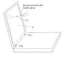
- FIG. 4is a side view of the determination of the position of an object using the mirrored signal in the preferred embodiment of the touch screen of the present invention.
- FIG. 4 ais top view of the determination of the position of an object using the mirrored signal in the preferred embodiment of the touch screen of the present invention.
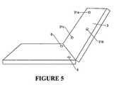
- FIG. 5is an illustration of the calibration in the preferred embodiment of the touch screen of the present invention.
- FIG. 6is a graph representing in the frequency domain the output from the imager in the processing module in the preferred embodiment of the touch screen of the present invention.
- FIG. 6 ais a graph representing in the frequency domain the filters responses on the signal from the imager in the preferred embodiment of the touch screen of the present invention.
- FIG. 6 bis a graph representing in the frequency domain the separation of the object from the background after two types of filtering in the preferred embodiment of the touch screen of the present invention.
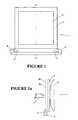
- FIG. 7is an illustration of a front view of the alternate embodiment of the touch screen of the present invention.
- FIG. 7 ais an illustration of a cross sectional view through X-X of the alternate embodiment of the touch screen of the present invention.
- FIG. 7 bis an illustration of rear illumination of the alternate embodiment of the touch screen of the present invention.
- FIG. 7 cis an illustration of rear illumination controlling the sense height of the alternate embodiment of the present invention.
- FIG. 7 dis a diagrammatic illustration of the pixels seen by a line scan camera and transmitted to the processing module in the alternate embodiment of the present invention.
- FIG. 8is a graph representing simple separation of an object from the background in the alternate embodiment of the present invention.
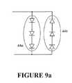
- FIG. 9 ashows a two section backlight driven by two wires of the present invention.
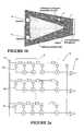
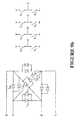
- FIG. 9 bshows a twelve section backlight driven by 4 wires of the present invention.
- FIG. 9 cshows a piece of distributed shift register backlight of the present invention.
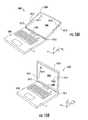
- FIGS. 10A-10Bshow an embodiment of a position detection system featuring a single camera remote from a body featuring the touch surface.
- FIGS. 10C-10Dshow an embodiment of a position detection system featuring cameras mounted to a body featuring the touch surface.
- FIG. 11is a flowchart showing exemplary steps in a method of single-touch calibration.
- FIG. 12is an illustration of calibration in another preferred embodiment of the present invention.
- FIG. 13is an illustration of calibration in yet another preferred embodiment of the present invention.
- the present inventionrelates to improvements in signal processing in the field of optical imaging touch screens.
- the optical touch screenuses front illumination and is comprised of a screen, a series of light sources, and at least two area scan cameras located in the same plane and at the periphery of the screen.
- the optical touch screenuses backlight illumination; the screen is surrounded by an array of light sources located behind the touch panel which are redirected across the surface of the touch panel. At least two line scan cameras are used in the same plane as the touch screen panel.
- a coordinate detection systemis configured to direct light through a touch surface, with the touch surface corresponding to the screen or a material above the screen.
- FIG. 3A block diagram of a general touch screen system 1 is shown in FIG. 3 .
- Informationflows from the cameras 6 to the video processing unit and computer, together referred to as the processing module 10 .
- the processing module 10performs many types of calculations including filtering, data sampling, and triangulation and controls the modulation of the illumination source 4 .
- the touch screen system 1is comprised of a monitor 2 , a touch screen panel 3 , at least two lights 4 , a processing module (not shown) and at least two area scan cameras 6 .
- the monitor 2which displays information to the user, is positioned behind the touch screen panel 3 .
- Below the touch screen panel 3 and the monitor 2are the area scan cameras 6 and light sources 4 .
- the light sources 4are preferably Light Emitting Diodes (LED) but may be another type of light source, for example, a fluorescent tube. LEDs are ideally used as they may be modulated as required, they do not have an inherent switching frequency.
- the cameras 6 and LEDs 4are in the same plane as the touch panel 3 .
- the viewing field 6 a of the area scan camera 6 and the radiation path 4 a of the LEDs 4are in the same plane and parallel to the touch panel 3 .
- an object 7shown as a finger
- FIG. 1 bthis principle is again illustrated.
- a signalis reflected back to the camera 6 . This indicates that a finger 7 is near to or touching the touch panel 3 .
- the location of the touch panel 3must be established. This is performed using another signal, a mirrored signal.
- the mirrored signaloccurs when the object 7 nears the touch panel 3 .
- the touch panel 3is preferably made from glass which has reflective properties.
- the finger 7is positioned at a distance 8 above the touch panel 3 and is mirrored 7 a in the touch panel 3 .
- the camera 6(only shown as the camera lens) images both the finger 7 and the reflected image 7 a .
- the image of finger 7is reflected 7 a in panel 3 ; this can be seen through the field lines 6 b , 6 c and virtual field line 6 d . This allows the camera 6 to image the reflected 7 a image of the finger 7 .
- the data produced from the camera 6corresponds to the position of the field lines 6 e , 6 b as they enter the camera 6 . This data is then fed into a processing module 10 for analysis.
- FIG. 2 aA section of the processing module 10 is shown in FIG. 2 a .
- a series of scanning imagers 13 and digital filters 11 and comparators 12implemented in software.
- there are 30,000 digital filters 11 and comparators 12broken up into 100 columns of 300 pixels, this forms a matrix similar to the matrix of pixels on the monitor 2 .
- FIG. 1A representation of this is shown in FIG.
- FIG. 2 bA more illustrated example of this matrix is shown in FIG. 2 b .
- Eight pixels 3 a - 3 hare connected, in groups of columns, to an image scanner 13 that is subsequently connected to a filter 11 and a comparator 12 (as part of the processing module 10 ).
- the numbers used in FIG. 2 bare used for illustration only; an accurate number of pixels could be greater or less in number.
- the pixels shown in this diagrammay not form this shape in the panel 3 , their shape will be dictated by the position and type of camera 6 used.
- finger 7 and mirrored finger 7 aactivates at least two pixels; two pixels are used for simplicity. This is shown by the field lines 6 e and 6 b entering the processing module 10 . This activates the software so the two signals pass through a digital filter 11 and a comparator 12 and results in a digital signal output 12 a - 12 e .
- the comparator 12compares the output from the filter 11 to a predetermined threshold value. If there is a finger 7 detected at the pixel in question, the output will be high, otherwise it will be low.
- the mirrored signalalso provides information about the position of the finger 7 in relation to the cameras 6 . It can determine the height 8 of the finger 7 above the panel 3 and its angular position. The information gathered from the mirrored signal is enough to determine where the finger 7 is in relation to the panel 3 without the finger 7 having to touch the panel 3 .
- FIGS. 4 and 4 ashow the positional information that is able to be obtained from the processing of the mirrored signal.
- the positional informationis given in polar co-ordinates.
- the positional informationrelates to the height of the finger 7 , and the position of the finger 7 over the panel 3 .
- the height that the finger 7 is above the panel 3can be seen in the distance between the outputs 12 a - 12 e .
- the finger 7is a height 8 above the panel 3 and the outputs 12 b and 12 e are producing a high signal.
- the other outputs 12 a , 12 dare producing a low signal. It has been found that the distance 9 between the high outputs 12 b , 12 e is twice as great as the actual height 8 of the finger above the panel 3 .
- the processing module 10modulates and collimates the LEDs 4 and sets a sampling rate.
- the LEDs 4are modulated, in the simplest embodiment the LEDs 4 are switched on and off at a predetermined frequency. Other types of modulation are possible, for example modulation with a sine wave. Modulating the LEDs 4 at a high frequency results in a frequency reading (when the finger 7 is sensed) that is significantly greater than any other frequencies produced by changing lights and shadows.
- the modulation frequencyis greater than 500 Hz but no more than 10 kHz.
- the cameras 6continuously generate an output, which due to data and time constraints is periodically sampled by the processing module 10 .
- the sampling rateis at least two times the modulation frequency; this is used to avoid aliasing.
- the modulation of the LEDs and the sampling frequencydoes not need to be synchronised.
- FIG. 6The output in the frequency domain from the scanning imager 13 is shown in FIG. 6 .
- FIG. 6there are two typical graphs, one showing when there is no object being sensed 21 and one showing when a finger is sensed 20 .
- both graphsthere is a region of movement of shadows 22 at approximately 5 to 20 Hz, and an AC mains frequency region 23 at approximately 50 to 60 Hz.
- no signalis transmitted to the area camera so there are no other peaks in the output.
- a signal 24corresponding to the LED modulated frequency, for example 500 Hz.
- the lower unwanted frequencies 22 , 23can be removed by various forms of filters. Types of filters can include comb, high pass, notch, and band pass filters.
- FIG. 6 athe output from the image scanner is shown with a couple of different filter responses 26 , 27 being applied to the signal 20 .
- a 500 Hz comb filter 26may be implemented (if using a 500 Hz modulation frequency). This will remove only the lowest frequencies.
- a more advanced implementationwould involve using a band pass 27 or notch filter. In this situation, all the data, except the region where the desired frequency is expected, is removed. In FIG. 6 a this is shown as a 500 Hz narrow band filter 27 applied to the signal 20 with a modulation frequency of 500 Hz.
- These outputs 30 , 31 from the filters 26 , 27are further shown in FIG. 6 b .
- the top graphshows the output 30 if a comb filter 26 is used while the bottom graph shows the output 31 when a band filter 27 is used.
- the band filter 27removes all unwanted signals while leaving the area of interest.
- Triangulationis known in the prior art and disclosed in U.S. Pat. No. 5,534,917 and U.S. Pat. No. 4,782,328, and are herein incorporated by reference.
- One preferred embodiment of the touch screen of the present inventionuses very quick and easy calibration that allows the touch screen to be used in any situation and moved to new locations, for example if the touch screen is manufactured as a lap top.
- Some embodiments of calibrationinvolve touching the panel 3 in three different locations 31 a , 31 b , 31 c , as shown in FIG. 5 ; this defines the touch plane of the touch panel 3 .
- These three touch points 31 a , 31 b , 31 cprovide enough information to the processing module (not shown) to calculate the position and size of the touch plane in relation to the touch panel 3 .
- Each touch point 31 a , 31 b , 31 cuses both mirrored and direct signals, as previously described, to generate the required data.
- These touch points 31 a , 31 b , 31 cmay vary around the panel 3 , they need not be the actual locations shown.
- ⁇may utilize fewer than three touches.
- some embodiments of calibrationutilize only a single touch.
- some embodiments of calibrationdo not even require a true “touch”—that is, a single “touch point” may be inferred even in the absence of contact between an object and a touch surface (e.g., the screen).
- FIG. 7shows an alternate embodiment of the touch screen of the present invention.
- the monitor 40is behind the touch panel 41 and around the sides and the lower edge of the panel 41 is an array of lights 42 . These point outwards towards the user and are redirected across the panel 41 by a diffusing plate 43 .
- the array of lights 42consists of numerous Light Emitting Diodes (LEDs).
- the diffusing plates 43are used redirect and diffuse the light emitted from the LEDs 42 across the panel 41 .
- At least two line-scan cameras 44are placed in the upper two corners of the panel 3 and are able to image an object. The cameras 44 can be alternately placed at any position around the periphery of the panel 41 .
- the bezel 45acts as a frame that stops the light radiation from being transmitted to the external environment.
- the bezel 45reflects the light rays into the cameras 44 so a light signal is always read into the camera 44 when there is no object near the touch panel 41 .
- the array of lights 42may be replaced with cold cathode tubes.
- a diffusing plate 43is not necessary as the outer tube of the cathode tube diffuses the light.
- the cold cathode tuberuns along the entire length of one side of the panel 41 . This provides a substantially even light intensity across the surface of the panel 41 .
- Cold cathode tubesare not preferably used as they are difficult and expensive to modify to suit the specific length of each side of the panel 41 . Using LED's allows greater flexibility in the size and shape of the panel 41 .
- the diffusing plate 43is used when the array of lights 42 consists of numerous LED's.
- the plate 43is used to diffuse the light emitted from an LED and redirect it across the surface of panel 41 .
- the light 47 from the LEDs 42begins its path at right angles to the panel 41 . Once it hits the diffusing plate 43 , it is redirected parallel to the panel 41 .
- the light 47travels slightly above the surface of the panel 41 so to illuminate the panel 41 .
- the light 47is collimated and modulated by the processing module (not shown) as previously described.
- the width 46 of the bezel 45can be increased or decreased. Increasing the width 46 of the bezel 45 increases the distance at which an object can be sensed. Similarly, the opposite applies to decreasing the width 10 of the bezel 45 .
- the line scan cameras 44consists of a CCD element, lens and driver control circuitry. When an image is seen by the cameras 44 a corresponding output signal is generated.
- the line scan cameras 44can read two light variables, namely direct light transmitted from the LED's 42 and reflected light.
- the method of sensing and reading direct and mirrored lightis similar to what has been previously described, but is simpler as line scan cameras can only read one column from the panel at once; it is not broken up into a matrix as when using an area scan camera. This is shown in FIG. 7 d where the panel 41 is broken up into sections 41 a - 41 d (what the line scan camera can see). The rest of the process has been described previously.
- the pixels shown in this diagrammay not form this shape in the panel 41 , their shape will be dictated by the position and type of camera 44 used.
- the line scan cameraswill be continuously reading the modulated light transmitted from the LEDs. This will result in the modulated frequency being present in the output whenever there is no object to interrupt the light path. When an object interrupts the light path, the modulated frequency in the output will not be present. This indicates that an object is in near to or touching the touch panel.
- the frequency present in the output signalis twice the height (twice the amplitude) than the frequency in the preferred embodiment. This is due to both signals (direct and mirrored) being present at once.
- the output from the camerais sampled when the LEDs are modulating on and off. This provides a reading of ambient light plus backlight 50 and a reading of ambient light alone 51 .
- an objectinterrupts the light from the LEDs, there is a dip 52 in the output 50 .
- the ambient reading 51is subtracted from the ambient and backlight reading 50 . This results in an output 54 where the dip 52 can be seen and thus simple thresholding can be used to identify the dip 52 .
- the backlightis broken up into a number of individual sections, 42 a to 42 f .
- One section or a subset of sectionsis activated at any time.
- Each of these sectionsis imaged by a subset of the pixels of the image sensors 44 .
- the backlight emittersare operated at higher current for shorter periods. As the average power of the emitter is limited, the peak brightness is increased. Increased peak brightness improves the ambient light performance.
- the backlight switchingmay advantageously be arranged such that while one section is illuminated, the ambient light level of another section is being measured by the signal processor. By simultaneously measuring ambient and backlit sections, speed is improved over single backlight systems.
- the backlight brightnessis adaptively adjusted by controlling LED current or pulse duration, as each section is activated so as to use the minimum average power whilst maintaining a constant signal to noise plus ambient ratio for the pixels that view that section.
- Control of the plurality of sections with a minimum number of control linesis achieved in one of several ways.
- the two groups of diodes 44 a , 44 bcan be wired antiphase and driven with bridge drive as shown in FIG. 9 a.
- diagonal bridge driveis used.
- 4 wiresare able to select 1 of 12 sections, 5 wires can drive 20 sections, and 6 wires drive 30 sections.
- a shift register 60is physically distributed around the backlight, and only two control lines are required.
- X-Y multiplexing arrangementsare well known in the art. For example an 8+4 wires are used to control a 4 digit display with 32 LED's.
- FIG. 9 bshows a 4 wire diagonal multiplexing arrangement with 12 LEDs.
- the control lines A, B, C, Dare driven by tristate outputs such as are commonly found at the pins of microprocessors such as the Microchip PIC family. Each tristate output has two electronic switches which are commonly mosfets. Either or neither of the switches can be turned on. To operate led L 1 a , switches A 1 and B 0 only are enabled. To operate L 1 B, A 0 and B 1 are operated. To operate L 2 a , A 1 and D 0 are enabled, and so on.
- This arrangementcan be used with any number of control lines, but is particularly advantageous for the cases of 4, 5, 6 control lines, where 12, 20, 30 LEDs can be controlled whilst the printed circuit board tracking remains simple. Where higher control numbers are used it may be advantageous to use degenerate forms where some of the possible LEDs are omitted to ease the practical interconnection difficulties.
- the diagonal multiplexing systemhas the following features it is advantageous where there are 4 or more control lines; it requires tri-state push-pull drivers on each control line; rather than using an x-y arrangement of control lines with led's at the crossings, the arrangement is represented by a ring of control lines with a pair of antiphase LED's arranged on each of the diagonals between the control lines.
- Each LEDcan be uniquely selected, and certain combinations can also be selected; and it uses the minimum possible number of wires where emc filtering is needed on the wires there is a significant saving in components.
- LEDslight emitting diodes
- IRinfrared
- other portions of the EM spectrum or even other types of energymay be used as applicable with appropriate sources and detection systems.
- touch areamay feature a static image or no image at all.
- the displaymay be viewed as one of a plurality of potential “touch surfaces.”
- touch surfacesinclude bodies separate from a display which are used for input purposes (e.g., a body positioned in view of one or more cameras for touch detection purposes).
- a “touch detection” systemmay be more broadly considered a “coordinate detection” system since, in addition to or instead of detecting touch of the touch surface, the system may detect a position/coordinate above the surface, such as when an object hovers but does not touch the surface.
- the use of the terms “touch detection,” “touch enabled,” and/or “touch surface”is not meant to exclude the possibility of detecting hover-based or other non-touch input.
- FIGS. 10A-10Bshow an embodiment of a position detection system 1000 featuring a single camera remote from a body featuring the touch surface.
- the coordinate detection systemcomprises a processing unit 1002 that comprises one or more processors and a computer-readable medium.
- the processing unitmay comprise a microprocessor, a digital signal processor, or microcontroller configured to drive components of the coordinate detection system and detect input based on one or more program components in RAM, ROM, or other memory comprising a computer-readable medium and/or by accessing stored code (e.g., from a disk).
- Processing unit 1002forms a part of a laptop computer and features a keyboard, trackpad, and power button.
- a display unit 1004carries a touch surface 1006 , which in these examples comprises a display interfaced to the processor and other components of processing unit 1002 .
- Two hinges 1012connect processing unit 1002 and display unit 1004 , allowing display unit 1004 to serve as a lid for processing unit 1002 .
- Other hinge arrangementscould be used, of course.
- Systems 1000 and/or 1001may each, for example, comprise a laptop, tablet, or “netbook” computer. However, system 1000 / 1001 may comprise a mobile device (e.g., a media player, personal digital assistant, flip-phone or other telephone form, etc.), or another computing system that includes one or more processors configured to function by program components.
- Coordinate detection system 1000 / 1001includes at least one imaging device.
- a single camera 1008is positioned on top surface T of processing unit 1002 in order to image some or all of the area of touch surface 1006 .
- two cameras 1009 and 1011are positioned on display unit 1004 at the corners thereof. It will be understood that other camera arrangements could be used, including, but not limited to, a single camera clipped or attached to display unit 1004 or multiple cameras 1008 on top surface T. Other embodiments can use a combination of cameras mounted to top surface T and display unit 1004 .
- Touch surface 1006may correspond to the top surface of the screen or a material or element positioned above the screen to protect the screen from damage and/or to serve other purposes.
- the touch surfacecorresponds to a display, but the same principles could apply to detecting position of an object relative to a surface that is not a display.
- Touch surface 1006can comprise any suitable material, preferably a material with reflective properties at least in the range of light used by the camera(s) of the position detection system.
- Processing unit 1002can be configured to utilize one or more cameras to image one or more objects and determine the position of the object(s) relative to touch surface 1006 .
- triangulation techniquescan be used with multiple cameras or other suitable position detection algorithms can be utilized.
- a mirror image of the objectcan be used in such determinations.
- a frame of referencewill be needed in order to use data from the camera(s) in position detection.
- FIG. 10Ashows display unit 1004 of system 1000 in a first orientation relative to processing unit 1002 , while in FIG. 10B the display unit is in a second orientation.
- display unit 1004 of system 1001is in a first orientation in FIG. 10C and in a second orientation in FIG. 10D .
- a plane corresponding to touch surface 1006meets the x-z plane at angle ⁇ 1 in FIGS. 10 A/ 10 C, while in FIGS. 10 B/D the plane of touch surface 1006 meets the x-z plane at an angle ⁇ 2 .
- coordinates detected by camera 1008may be found in terms of distance, bearing, and inclination from the x-z plane.
- the coordinatescould have different meanings. For instance, a hover gesture may be triggered based on determining a user's finger or another object is within a given distance from the screen.
- the orientation of the screenwould need to be known to make use of the distance/bearing/inclination to determine a position relative to the surface.
- the relative position of touch surface 1006 to processing unit 1002may not be needed for coordinate detection, but an initial calibration may be needed in order to determine where the surface lies in order to interpret input. Additionally, if touch surface 1006 were elsewhere from the display, the plane of the touch surface would be needed.
- a three-touch calibrationcan be performed in order to ascertain the plane of touch surface 1006 , since a plane can be defined by three points.
- the multiple-touch routinemay become tiresome for a user. For example, in an embodiment such as FIGS. 10A-10B , each time the position of a notebook computer's display is adjusted, the calibration routine would need repeating.
- Some presently-disclosed embodimentscan utilize a simpler calibration routine. Rather than relying on three touch points, a single-touch calibration sequence can be supported, such as by integrating the single-touch calibration sequence into a background process. This can allow for real-time updates to calibration, which may be especially advantageous when a relative position of a touch surface and imaging camera(s) is likely to change, such as in the examples of FIGS. 10A-10B . However, the same routine can allow for simpler calibration of systems in which one or more cameras move with the touch surface, such as in FIGS. 10C-10D .
- the position detection systemis configured to access data regarding one or more physical or other features at known locations relative to the touch surface. This data can be used along with sensor information to reduce the number of touches required to obtain the three points used to define a plane corresponding to touch surface 1016 .
- FIG. 11provides an example of a method 1100 of single-touch calibration.
- the methodmay be carried out by one or more software routines, such as a system driver in a computing device featuring one or more cameras.
- the methodmay be carried out by dedicated image processing hardware (e.g., a digital signal processor or microcontroller associated with the position detection system).
- Block 1102represents using sensor data to determine a location of a touch.
- a point P 1is illustrated to represent a point at which an object touches the screen.
- a user of the devicemay be prompted to touch the screen at a particular location, or at any location.
- various interactions with the devicecan be tracked and used as a basis for updating a coordinate system.
- occurrence of the touchcan be identified by tracking motion of an interruption in light (and/or motion of light reflected from an object into the camera) until the tracked motion coincides with another tracked motion.
- the touch pointmay correspond to a point at which an image and its mirror image coincide.
- Block 1104represents accessing data identifying one or more touch surface “landmarks,” which can include any feature that can be imaged by the camera(s) and is at a known position relative to the touch surface.
- the feature(s)may be features of a body comprising the touch surface or another feature visible to the camera(s).
- FIGS. 10A-10Bmodifications have been made to the bezel of display unit 1004 as shown at 1014 and 1016 .
- the modificationsmay include bumps, tabs, or other protrusions or changes in the bezel shape, and are shown in a somewhat exaggerated view in FIGS. 10A-10B .
- the modificationsmay touch surface 1016 or may be positioned near touch surface 1016 but may not actually touch the surface. As can be seen at 1014 ′ and 1016 ′, however, the modifications do create mirror images in touch surface 1016 .
- FIGS. 10C-10Ddo not feature modifications, but illustrate an embodiment in which other physical features of the position detection system are used in the calibration sequence.
- hinges 1012are at a known location relative to display unit 1004 and create mirror images 1012 ′.
- some embodimentscan utilize the landmarks themselves and may not need to image both landmarks and mirror images thereof.
- Block 1104can represent accessing data indicating an expected location of a physical feature.
- data accessed by the calibration routinemay indicate an expected range of pixel addresses for registering an image of modification 1014 and its mirror image 1014 ′, and/or data identifying a known position of modification 1014 relative to surface 1016 .
- expected coordinates for hinges 1012may be provided.
- no specific data regarding expected locationsis needed.
- the knowledge of the expected featurescan simply be a part of the algorithm carrying out the routine to detect the position of the plane.
- Block 1106represents using sensor data to locate landmarks and/or mirror images thereof.
- camera 1008 of FIGS. 10A-10B or cameras 1109 / 1111 of FIGS. 10C-10Dcan be used to sample light reflected from surface 1006 and other light traveling in a space above surface 1006 (assuming no touches occurring during the sample).
- the imagewill include four items: direct images of two hinges 1012 and their mirror images 1012 ′.
- the imagewill include direct images of modifications 1014 and 1016 along with mirror images 1014 ′ and 1016 ′.
- the plane of touch surface 1006is not known, so the landmarks and their respective mirror images may not be discernable from one another—in the image, they simply appear as four objects.
- the calibration routinecan work based on the fact that the landmarks and mirror images thereof about a reflection plane are known to have been detected.
- the plane of touch surface 1006will be the plane that includes touch point P 1 and also corresponds to a plane of reflection that would produce the pairs of landmarks and mirror images as detected.
- the calibration routinemay, for example, determine a plurality of coordinate sets for the objects and identify one or more potential planes that would result in two of the objects being “real” and two objects being “virtual.” The true plane can be found amongst the potential planes by determining which potential plane also would include the detected touch point.
- the landmarksmay be formed to intersect with the reflection plane.
- the plane of touch surfacein that case would be a plane that includes the landmarks and the single touch point. Accordingly, embodiments include calibration using features that are reflected in, but do not touch, the touch surface or can be used with landmarks shaped to contact and/or be coplanar with the touch surface.
- the plane of touch surfacecould be figured out by determining 3 non collinear points 31 a , 31 b , 31 c , as shown in FIG. 5 or FIG. 12 .
- FIG. 12depicts the touch screen panel 3 of FIG. 5 and three non collinear points, but in this example two of the non collinear points are features of the display (hinges, in this example).
- the known non collinear pointscan be identified in the image and, along with the single touch, can be used to define the touch plane of the touch panel 3 .
- the single touchmay not even need to contact the display in order to determine the “touch point.”
- two of the three non collinear pointscan be determined from the fixed hinge positions or other landmarks and the other point (i.e. the “touch point”) determined as being the point laying on the line halfway between the object and its mirror image on the touch surface.
- the touch planecan be determined solely from the object moving toward the single “touch point” and the object's mirror image, as the line connecting the two is normal to the touch plane and the mid point along this line lies on the plane as shown in FIG. 12 .
- the plane normal and this point on the touch planefully define the touch plane.
- the plane passing through p 1 , p 2 , and p 3can be defined as the set of all points (x,y,z) that satisfy the following determinant equations:
- block 1108represents defining the touch plane as the plane that intersects the location of the touch point and also generates proper coordinates for the known location of the landmarks.
- the calibration routinecan allow for some variance from the ideal mathematical solution, such as providing for a margin of error in the plane definition.
- a triangulation-based position detection algorithmmay rely on a four-point calibration sequence to determine bearings relative to two cameras (e.g., cameras arranged as in FIGS. 10C-D ). Two of the four points may be inferred based on the landmarks in some embodiments.
- FIG. 13illustrates yet another embodiment of single-point calibration.
- the planeis determined solely from the object moving toward the single “touch point” and the object's mirror image.
- this methodutilizes the line connecting the object's image and its mirror image, which is normal to the touch plane, and the mid point along this line (which corresponds to the touch point and thus lies on the plane).
- the plane'normalline from a point 31 a of the object and a corresponding point 31 b on its mirror image
- this mid point 31 c on the touch planefully define the touch plane.
- a corresponding methodcan comprise imaging the object and its mirror image using one or more imaging sensors. Based on the motion of the object and its mirror image, the line ( 31 a - 31 b ) can be determined, with the midpoint found to define the plane. As is known, in a three-dimensional space, one way of defining a plane is by specifying a point and a normal vector to the plane.
- r 0be the position vector of some known point P 0 in the plane
- nbe a nonzero vector normal to the plane.
- a computing devicecan include any suitable arrangement of components that provide a result conditioned on one or more inputs.
- Suitable computing devicesinclude multipurpose microprocessor-based computer systems accessing stored software, but also application-specific integrated circuits and other programmable logic, and combinations thereof. Any suitable programming, scripting, or other type of language or combinations of languages may be used to implement the teachings contained herein in software.
- Embodiments of the methods disclosed hereinmay be executed by one or more suitable computing devices.
- Such system(s)may comprise one or more computing devices adapted to perform one or more embodiments of the methods disclosed herein.
- computing devicesmay access one or more computer-readable media that embody computer-readable instructions which, when executed by at least one computer, cause the at least one computer to implement one or more embodiments of the methods of the present subject matter.
- programmingcan configure a processing unit of digital signal processor (DSP) or a CPU of a computing system to carry out an embodiment of a method to determine the location of a plane and to otherwise function as noted herein.
- DSPdigital signal processor
- the softwaremay comprise one or more components, processes, and/or applications. Additionally or alternatively to software, the computing device(s) may comprise circuitry that renders the device(s) operative to implement one or more of the methods of the present subject matter.
- Any suitable computer-readable medium or mediamay be used to implement or practice the presently-disclosed subject matter, including, but not limited to, diskettes, drives, magnetic-based storage media, optical storage media, including disks (including CD-ROMS, DVD-ROMS, and variants thereof), flash, RAM, ROM, and other memory devices, and the like.
Landscapes
- Engineering & Computer Science (AREA)
- General Engineering & Computer Science (AREA)
- Theoretical Computer Science (AREA)
- Human Computer Interaction (AREA)
- Physics & Mathematics (AREA)
- General Physics & Mathematics (AREA)
- Length Measuring Devices By Optical Means (AREA)
- Position Input By Displaying (AREA)
Abstract
Description
ax1+by1+cz1+d=0
ax2+by2+cz2+d=0
ax3by3+cz3+d=0
N(dot)(r−r0)=0
which expands to
nx(x−x0)+ny(y−y0)+nz(z−z0)=0
Claims (26)
Priority Applications (1)
| Application Number | Priority Date | Filing Date | Title |
|---|---|---|---|
| US12/709,803US8508508B2 (en) | 2003-02-14 | 2010-02-22 | Touch screen signal processing with single-point calibration |
Applications Claiming Priority (7)
| Application Number | Priority Date | Filing Date | Title |
|---|---|---|---|
| NZ524211 | 2003-02-14 | ||
| NZ52421103 | 2003-02-14 | ||
| NZNZ524211 | 2003-02-14 | ||
| PCT/NZ2004/000029WO2004072843A1 (en) | 2003-02-14 | 2004-02-16 | Touch screen signal processing |
| US11/033,183US7629967B2 (en) | 2003-02-14 | 2005-01-11 | Touch screen signal processing |
| US12/578,165US8466885B2 (en) | 2003-02-14 | 2009-10-13 | Touch screen signal processing |
| US12/709,803US8508508B2 (en) | 2003-02-14 | 2010-02-22 | Touch screen signal processing with single-point calibration |
Related Parent Applications (1)
| Application Number | Title | Priority Date | Filing Date |
|---|---|---|---|
| US12/578,165Continuation-In-PartUS8466885B2 (en) | 2003-02-14 | 2009-10-13 | Touch screen signal processing |
Publications (2)
| Publication Number | Publication Date |
|---|---|
| US20100207911A1 US20100207911A1 (en) | 2010-08-19 |
| US8508508B2true US8508508B2 (en) | 2013-08-13 |
Family
ID=42559468
Family Applications (1)
| Application Number | Title | Priority Date | Filing Date |
|---|---|---|---|
| US12/709,803Expired - LifetimeUS8508508B2 (en) | 2003-02-14 | 2010-02-22 | Touch screen signal processing with single-point calibration |
Country Status (1)
| Country | Link |
|---|---|
| US (1) | US8508508B2 (en) |
Cited By (9)
| Publication number | Priority date | Publication date | Assignee | Title |
|---|---|---|---|---|
| US20120120028A1 (en)* | 2010-11-11 | 2012-05-17 | Seiko Epson Corporation | Optical detection system and program |
| US20130120319A1 (en)* | 2005-10-31 | 2013-05-16 | Extreme Reality Ltd. | Methods, Systems, Apparatuses, Circuits and Associated Computer Executable Code for Detecting Motion, Position and/or Orientation of Objects Within a Defined Spatial Region |
| US20150205376A1 (en)* | 2014-01-21 | 2015-07-23 | Seiko Epson Corporation | Position detecting device, position detecting system, and controlling method of position detecting device |
| US9652082B1 (en) | 2014-08-20 | 2017-05-16 | Amazon Technologies, Inc. | Space efficient electronic device component configurations |
| US9823782B2 (en)* | 2015-11-20 | 2017-11-21 | International Business Machines Corporation | Pre-touch localization on a reflective surface |
| US9880668B2 (en) | 2013-09-11 | 2018-01-30 | Beijing Lenovo Software Ltd. | Method for identifying input information, apparatus for identifying input information and electronic device |
| US10606468B2 (en) | 2015-11-20 | 2020-03-31 | International Business Machines Corporation | Dynamic image compensation for pre-touch localization on a reflective surface |
| US11281337B1 (en) | 2019-09-24 | 2022-03-22 | Apple Inc. | Mirror accessory for camera based touch detection |
| US11594159B2 (en) | 2019-01-09 | 2023-02-28 | Dolby Laboratories Licensing Corporation | Display management with ambient light compensation |
Families Citing this family (26)
| Publication number | Priority date | Publication date | Assignee | Title |
|---|---|---|---|---|
| US7629967B2 (en) | 2003-02-14 | 2009-12-08 | Next Holdings Limited | Touch screen signal processing |
| US8456447B2 (en) | 2003-02-14 | 2013-06-04 | Next Holdings Limited | Touch screen signal processing |
| US7538759B2 (en) | 2004-05-07 | 2009-05-26 | Next Holdings Limited | Touch panel display system with illumination and detection provided from a single edge |
| EP2135155B1 (en) | 2007-04-11 | 2013-09-18 | Next Holdings, Inc. | Touch screen system with hover and click input methods |
| KR20100055516A (en) | 2007-08-30 | 2010-05-26 | 넥스트 홀딩스 인코포레이티드 | Optical touchscreen with improved illumination |
| WO2009029764A1 (en) | 2007-08-30 | 2009-03-05 | Next Holdings, Inc. | Low profile touch panel systems |
| US8405636B2 (en) | 2008-01-07 | 2013-03-26 | Next Holdings Limited | Optical position sensing system and optical position sensor assembly |
| US8395370B2 (en) | 2010-03-25 | 2013-03-12 | Silego Technology, Inc. | Capacitive coupling based sensor |
| US9331694B2 (en)* | 2010-03-25 | 2016-05-03 | Silego Technology, Inc. | Capacitive coupling based proximity sensor |
| US20110270358A1 (en)* | 2010-04-30 | 2011-11-03 | Medtronic, Inc. | Implantable medical device programming using gesture-based control |
| EP2434387B1 (en) | 2010-09-24 | 2020-01-08 | 2236008 Ontario Inc. | Portable electronic device and method therefor |
| GB2496803A (en) | 2010-09-24 | 2013-05-22 | Research In Motion Ltd | Transitional view on a portable electronic device |
| CN103221914B (en) | 2010-09-24 | 2020-01-31 | 黑莓有限公司 | Portable electronic device and control method thereof |
| US9019239B2 (en)* | 2010-11-29 | 2015-04-28 | Northrop Grumman Systems Corporation | Creative design systems and methods |
| TWI450155B (en)* | 2011-02-15 | 2014-08-21 | Wistron Corp | Method and system for calculating calibration information for an optical touch apparatus |
| US20120320077A1 (en)* | 2011-06-17 | 2012-12-20 | Microsoft Corporation | Communicating status and expression |
| US8860695B2 (en)* | 2011-08-05 | 2014-10-14 | Pixart Imaging Inc. | Optical touch system and electronic apparatus including the same |
| US8859971B2 (en)* | 2011-10-14 | 2014-10-14 | Blackberry Limited | Light redirection in optical navigation |
| TW201342137A (en)* | 2012-04-10 | 2013-10-16 | Pixart Imaging Inc | Optical operation system |
| US10013026B2 (en)* | 2012-12-20 | 2018-07-03 | Dell Products L.P. | Method and system for auto calibration of display using ambient light sensors |
| EP3036602A4 (en) | 2013-08-22 | 2017-04-12 | Hewlett-Packard Development Company, L.P. | Projective computing system |
| CN103780812A (en)* | 2013-11-26 | 2014-05-07 | 广东欧珀移动通信有限公司 | Display apparatus and shooting display method thereof |
| US9317150B2 (en)* | 2013-12-28 | 2016-04-19 | Intel Corporation | Virtual and configurable touchscreens |
| CN105334953B (en)* | 2014-07-30 | 2018-10-12 | 联想(北京)有限公司 | A kind of operating body movement locus recognition methods, microcontroller and electronic equipment |
| US9984209B2 (en) | 2015-02-13 | 2018-05-29 | Medtronic, Inc. | Graphical controls for programming medical device operation |
| CN107122084B (en)* | 2017-04-27 | 2020-10-02 | 海信视像科技股份有限公司 | Method and device for identifying touch operation on infrared touch screen and terminal equipment |
Citations (496)
| Publication number | Priority date | Publication date | Assignee | Title |
|---|---|---|---|---|
| US844152A (en) | 1906-02-21 | 1907-02-12 | William Jay Little | Camera. |
| US2407680A (en) | 1945-03-02 | 1946-09-17 | Minnesota Mining & Mfg | Reflex light reflector |
| US2769374A (en) | 1951-10-19 | 1956-11-06 | Sick Erwin | Electrical light screen |
| US3025406A (en) | 1959-02-05 | 1962-03-13 | Flightex Fabrics Inc | Light screen for ballistic uses |
| US3128340A (en) | 1961-12-21 | 1964-04-07 | Bell Telephone Labor Inc | Electrographic transmitter |
| US3187185A (en) | 1960-12-22 | 1965-06-01 | United States Steel Corp | Apparatus for determining surface contour |
| US3360654A (en) | 1964-05-06 | 1967-12-26 | Sick Erwin | Light barrier for preventing machine accidents including fail safe device |
| US3478220A (en) | 1966-05-11 | 1969-11-11 | Us Navy | Electro-optic cursor manipulator with associated logic circuitry |
| US3563771A (en) | 1968-02-28 | 1971-02-16 | Minnesota Mining & Mfg | Novel black glass bead products |
| US3613066A (en) | 1968-10-22 | 1971-10-12 | Cii | Computer input equipment |
| US3764813A (en) | 1972-04-12 | 1973-10-09 | Bell Telephone Labor Inc | Coordinate detection system |
| US3775560A (en) | 1972-02-28 | 1973-11-27 | Univ Illinois | Infrared light beam x-y position encoder for display devices |
| US3810804A (en) | 1970-09-29 | 1974-05-14 | Rowland Dev Corp | Method of making retroreflective material |
| US3830682A (en) | 1972-11-06 | 1974-08-20 | Rowland Dev Corp | Retroreflecting signs and the like with novel day-night coloration |
| US3857022A (en) | 1973-11-15 | 1974-12-24 | Integrated Sciences Corp | Graphic input device |
| US3860754A (en) | 1973-05-07 | 1975-01-14 | Univ Illinois | Light beam position encoder apparatus |
| US4107522A (en) | 1975-11-11 | 1978-08-15 | Erwin Sick Gesellschaft Mit Beschrankter Haftung Optik-Elektronik | Rotary beam light curtain |
| US4144449A (en) | 1977-07-08 | 1979-03-13 | Sperry Rand Corporation | Position detection apparatus |
| GB1575420A (en) | 1978-02-01 | 1980-09-24 | Marconi Co Ltd | Position resolving apparatus |
| US4243879A (en) | 1978-04-24 | 1981-01-06 | Carroll Manufacturing Corporation | Touch panel with ambient light sampling |
| US4243618A (en) | 1978-10-23 | 1981-01-06 | Avery International Corporation | Method for forming retroreflective sheeting |
| US4247767A (en) | 1978-04-05 | 1981-01-27 | Her Majesty The Queen In Right Of Canada, As Represented By The Minister Of National Defence | Touch sensitive computer input device |
| US4329037A (en) | 1981-06-08 | 1982-05-11 | Container Corporation Of America | Camera structure |
| US4420261A (en) | 1980-09-02 | 1983-12-13 | Lowbar, Inc. | Optical position location apparatus |
| US4459476A (en) | 1982-01-19 | 1984-07-10 | Zenith Radio Corporation | Co-ordinate detection system |
| US4468694A (en) | 1980-12-30 | 1984-08-28 | International Business Machines Corporation | Apparatus and method for remote displaying and sensing of information using shadow parallax |
| US4486363A (en) | 1982-09-30 | 1984-12-04 | Amerace Corporation | Method and apparatus for embossing a precision optical pattern in a resinous sheet |
| US4507557A (en) | 1983-04-01 | 1985-03-26 | Siemens Corporate Research & Support, Inc. | Non-contact X,Y digitizer using two dynamic ram imagers |
| US4542375A (en) | 1982-02-11 | 1985-09-17 | At&T Bell Laboratories | Deformable touch sensitive surface |
| US4550250A (en) | 1983-11-14 | 1985-10-29 | Hei, Inc. | Cordless digital graphics input device |
| US4553842A (en) | 1983-05-09 | 1985-11-19 | Illinois Tool Works Inc. | Two dimensional optical position indicating apparatus |
| US4558313A (en) | 1981-12-31 | 1985-12-10 | International Business Machines Corporation | Indicator to data processing interface |
| US4601861A (en) | 1982-09-30 | 1986-07-22 | Amerace Corporation | Methods and apparatus for embossing a precision optical pattern in a resinous sheet or laminate |
| GB2176282A (en) | 1985-06-05 | 1986-12-17 | Illinois Tool Works | Optical position locating device |
| US4672364A (en) | 1984-06-18 | 1987-06-09 | Carroll Touch Inc | Touch input device having power profiling |
| US4673918A (en) | 1984-11-29 | 1987-06-16 | Zenith Electronics Corporation | Light guide having focusing element and internal reflector on same face |
| US4688933A (en) | 1985-05-10 | 1987-08-25 | The Laitram Corporation | Electro-optical position determining system |
| EP0181196A3 (en) | 1984-11-06 | 1987-09-02 | Arie J. Kurtzig | Removable touchscreen |
| US4703316A (en) | 1984-10-18 | 1987-10-27 | Tektronix, Inc. | Touch panel input apparatus |
| US4710760A (en) | 1985-03-07 | 1987-12-01 | American Telephone And Telegraph Company, At&T Information Systems Inc. | Photoelastic touch-sensitive screen |
| US4737631A (en) | 1985-05-17 | 1988-04-12 | Alps Electric Co., Ltd. | Filter of photoelectric touch panel with integral spherical protrusion lens |
| US4742221A (en) | 1985-05-17 | 1988-05-03 | Alps Electric Co., Ltd. | Optical coordinate position input device |
| US4746770A (en) | 1987-02-17 | 1988-05-24 | Sensor Frame Incorporated | Method and apparatus for isolating and manipulating graphic objects on computer video monitor |
| US4762990A (en) | 1985-10-21 | 1988-08-09 | International Business Machines Corporation | Data processing input interface determining position of object |
| US4766424A (en) | 1984-03-30 | 1988-08-23 | Zenith Electronics Corporation | Light collecting and redirecting means |
| US4782328A (en) | 1986-10-02 | 1988-11-01 | Product Development Services, Incorporated | Ambient-light-responsive touch screen data input method and system |
| GB2204126A (en) | 1987-04-28 | 1988-11-02 | Wells Gardner Electronics | Optical position determining apparatus |
| US4811004A (en) | 1987-05-11 | 1989-03-07 | Dale Electronics, Inc. | Touch panel system and method for using same |
| US4818826A (en) | 1986-09-19 | 1989-04-04 | Alps Electric Co., Ltd. | Coordinate input apparatus including a detection circuit to determine proper stylus position |
| US4822145A (en) | 1986-05-14 | 1989-04-18 | Massachusetts Institute Of Technology | Method and apparatus utilizing waveguide and polarized light for display of dynamic images |
| US4831455A (en) | 1986-02-21 | 1989-05-16 | Canon Kabushiki Kaisha | Picture reading apparatus |
| US4851664A (en) | 1988-06-27 | 1989-07-25 | United States Of America As Represented By The Secretary Of The Navy | Narrow band and wide angle hemispherical interference optical filter |
| US4868551A (en) | 1983-10-28 | 1989-09-19 | Thomson-Csf | Sensitive display device comprising a scanned screen |
| US4868912A (en) | 1986-11-26 | 1989-09-19 | Digital Electronics | Infrared touch panel |
| US4888479A (en) | 1988-03-07 | 1989-12-19 | Sony Corporation | Touch panel apparatus |
| US4893120A (en) | 1986-11-26 | 1990-01-09 | Digital Electronics Corporation | Touch panel using modulated light |
| US4916308A (en) | 1988-10-17 | 1990-04-10 | Tektronix, Inc. | Integrated liquid crystal display and optical touch panel |
| DE3836429A1 (en) | 1988-10-26 | 1990-05-03 | Paul Nolden | Sensor matrix for screens |
| US4928094A (en) | 1988-01-25 | 1990-05-22 | The Boeing Company | Battery-operated data collection apparatus having an infrared touch screen data entry device |
| US4943806A (en) | 1984-06-18 | 1990-07-24 | Carroll Touch Inc. | Touch input device having digital ambient light sampling |
| US4980547A (en) | 1985-05-24 | 1990-12-25 | Wells-Gardner Electronics Corp. | Light distribution and detection apparatus |
| US4990901A (en) | 1987-08-25 | 1991-02-05 | Technomarket, Inc. | Liquid crystal display touch screen having electronics on one side |
| US5025411A (en) | 1986-12-08 | 1991-06-18 | Tektronix, Inc. | Method which provides debounced inputs from a touch screen panel by waiting until each x and y coordinates stop altering |
| US5025314A (en) | 1990-07-30 | 1991-06-18 | Xerox Corporation | Apparatus allowing remote interactive use of a plurality of writing surfaces |
| EP0420335A3 (en) | 1989-09-26 | 1991-07-24 | N.V. Philips' Gloeilampenfabrieken | High pressure gas discharge lamp |
| US5043751A (en) | 1990-06-08 | 1991-08-27 | Richard Rice | Self-bracing credit-card-size camera for single-shot emergency use, and method for manufacture and distribution |
| US5097516A (en) | 1991-02-28 | 1992-03-17 | At&T Bell Laboratories | Technique for illuminating a surface with a gradient intensity line of light to achieve enhanced two-dimensional imaging |
| US5103085A (en) | 1990-09-05 | 1992-04-07 | Zimmerman Thomas G | Photoelectric proximity detector and switch |
| US5103249A (en) | 1990-10-24 | 1992-04-07 | Lauren Keene | Folding disposable camera apparatus in combination with instant film |
| US5105186A (en) | 1990-05-25 | 1992-04-14 | Hewlett-Packard Company | Lcd touch screen |
| US5109435A (en) | 1988-08-08 | 1992-04-28 | Hughes Aircraft Company | Segmentation method for use against moving objects |
| US5130794A (en) | 1990-03-29 | 1992-07-14 | Ritchey Kurtis J | Panoramic display system |
| US5140647A (en) | 1989-12-18 | 1992-08-18 | Hitachi, Ltd. | Image joining method and system |
| US5148015A (en) | 1990-12-24 | 1992-09-15 | Pitney Bowes Inc. | Touch switch input device for computer system |
| US5162618A (en) | 1990-11-16 | 1992-11-10 | Exzec, Inc. | Acoustic touch position sensor with first order lamb wave reflective arrays |
| US5162783A (en) | 1990-07-23 | 1992-11-10 | Akzo N.V. | Infrared touch screen device for a video monitor |
| US5164714A (en) | 1988-06-20 | 1992-11-17 | Amp Incorporated | Modulated touch entry system and method with synchronous detection |
| US5168531A (en) | 1991-06-27 | 1992-12-01 | Digital Equipment Corporation | Real-time recognition of pointing information from video |
| US5177328A (en) | 1990-06-28 | 1993-01-05 | Kabushiki Kaisha Toshiba | Information processing apparatus |
| US5179369A (en) | 1989-12-06 | 1993-01-12 | Dale Electronics, Inc. | Touch panel and method for controlling same |
| US5196836A (en) | 1991-06-28 | 1993-03-23 | International Business Machines Corporation | Touch panel display |
| US5196835A (en) | 1988-09-30 | 1993-03-23 | International Business Machines Corporation | Laser touch panel reflective surface aberration cancelling |
| US5200851A (en) | 1992-02-13 | 1993-04-06 | Minnesota Mining And Manufacturing Company | Infrared reflecting cube-cornered sheeting |
| US5200861A (en) | 1991-09-27 | 1993-04-06 | U.S. Precision Lens Incorporated | Lens systems |
| US5233502A (en) | 1992-03-11 | 1993-08-03 | International Business Machines Corp. | Removable and reversible display device for portable computer |
| GB2263765A (en) | 1992-01-25 | 1993-08-04 | Paul Philip Oliver | Touch screen systems |
| US5239152A (en) | 1990-10-30 | 1993-08-24 | Donnelly Corporation | Touch sensor panel with hidden graphic mode |
| US5239373A (en) | 1990-12-26 | 1993-08-24 | Xerox Corporation | Video computational shared drawing space |
| US5272470A (en) | 1991-10-10 | 1993-12-21 | International Business Machines Corporation | Apparatus and method for reducing system overhead while inking strokes in a finger or stylus-based input device of a data processing system |
| US5317140A (en) | 1992-11-24 | 1994-05-31 | Dunthorn David I | Diffusion-assisted position location particularly for visual pen detection |
| US5359155A (en) | 1993-03-25 | 1994-10-25 | Tiger Scientific Corp. | Illumination apparatus for a digitizer tablet |
| US5374971A (en) | 1993-03-12 | 1994-12-20 | Picturetel Corporation | Two-view video camera stand and support method |
| EP0347725B1 (en) | 1988-06-22 | 1995-02-01 | Wacom Company, Ltd. | Electronic blackboard and accessories such as writing tools |
| US5414413A (en) | 1988-06-14 | 1995-05-09 | Sony Corporation | Touch panel apparatus |
| US5422494A (en) | 1992-10-16 | 1995-06-06 | The Scott Fetzer Company | Barrier transmission apparatus |
| EP0657841A1 (en) | 1993-12-07 | 1995-06-14 | AT&T Corp. | Sensing stylus position using single 1-D imge sensor |
| US5448263A (en) | 1991-10-21 | 1995-09-05 | Smart Technologies Inc. | Interactive display system |
| US5457289A (en) | 1994-03-16 | 1995-10-10 | Microtouch Systems, Inc. | Frontally shielded capacitive touch sensor system |
| US5483261A (en) | 1992-02-14 | 1996-01-09 | Itu Research, Inc. | Graphical input controller and method with rear screen image detection |
| US5483603A (en) | 1992-10-22 | 1996-01-09 | Advanced Interconnection Technology | System and method for automatic optical inspection |
| US5490655A (en) | 1993-09-16 | 1996-02-13 | Monger Mounts, Inc. | Video/data projector and monitor ceiling/wall mount |
| US5502568A (en) | 1993-03-23 | 1996-03-26 | Wacom Co., Ltd. | Optical position detecting unit, optical coordinate input unit and optical position detecting method employing a pattern having a sequence of 1's and 0's |
| US5525764A (en) | 1994-06-09 | 1996-06-11 | Junkins; John L. | Laser scanning graphic input system |
| US5528263A (en) | 1994-06-15 | 1996-06-18 | Daniel M. Platzker | Interactive projected video image display system |
| US5528290A (en) | 1994-09-09 | 1996-06-18 | Xerox Corporation | Device for transcribing images on a board using a camera based board scanner |
| US5537107A (en) | 1991-01-29 | 1996-07-16 | Sony Corporation | Remote control unit for video apparatus |
| US5541372A (en) | 1992-06-15 | 1996-07-30 | U.S. Philips Corporation | Force activated touch screen measuring deformation of the front panel |
| US5554828A (en) | 1995-01-03 | 1996-09-10 | Texas Instruments Inc. | Integration of pen-based capability into a field emission device system |
| US5581276A (en) | 1992-09-08 | 1996-12-03 | Kabushiki Kaisha Toshiba | 3D human interface apparatus using motion recognition based on dynamic image processing |
| US5581637A (en) | 1994-12-09 | 1996-12-03 | Xerox Corporation | System for registering component image tiles in a camera-based scanner device transcribing scene images |
| US5591945A (en) | 1995-04-19 | 1997-01-07 | Elo Touchsystems, Inc. | Acoustic touch position sensor using higher order horizontally polarized shear wave propagation |
| US5594502A (en) | 1993-01-20 | 1997-01-14 | Elmo Company, Limited | Image reproduction apparatus |
| US5594469A (en) | 1995-02-21 | 1997-01-14 | Mitsubishi Electric Information Technology Center America Inc. | Hand gesture machine control system |
| US5617312A (en) | 1993-11-19 | 1997-04-01 | Hitachi, Ltd. | Computer system that enters control information by means of video camera |
| US5638092A (en) | 1994-12-20 | 1997-06-10 | Eng; Tommy K. | Cursor control system |
| EP0762319A3 (en) | 1995-08-24 | 1997-06-11 | Symbios Logic Inc | Graphical input apparatus and method |
| US5670755A (en) | 1994-04-21 | 1997-09-23 | Samsung Display Devices Co., Ltd. | Information input apparatus having functions of both touch panel and digitizer, and driving method thereof |
| US5686942A (en) | 1994-12-01 | 1997-11-11 | National Semiconductor Corporation | Remote computer input system which detects point source on operator |
| US5698845A (en) | 1995-05-23 | 1997-12-16 | Stanley Electric Co., Ltd. | Optical detection apparatus for detecting light interruption |
| US5712024A (en) | 1995-03-17 | 1998-01-27 | Hitachi, Ltd. | Anti-reflector film, and a display provided with the same |
| US5729704A (en) | 1993-07-21 | 1998-03-17 | Xerox Corporation | User-directed method for operating on an object-based model data structure through a second contextual image |
| US5734375A (en) | 1995-06-07 | 1998-03-31 | Compaq Computer Corporation | Keyboard-compatible optical determination of object's position |
| US5737740A (en) | 1994-06-27 | 1998-04-07 | Numonics | Apparatus and method for processing electronic documents |
| US5736686A (en) | 1995-03-01 | 1998-04-07 | Gtco Corporation | Illumination apparatus for a digitizer tablet with improved light panel |
| US5739479A (en) | 1996-03-04 | 1998-04-14 | Elo Touchsystems, Inc. | Gentle-bevel flat acoustic wave touch sensor |
| US5745116A (en) | 1996-09-09 | 1998-04-28 | Motorola, Inc. | Intuitive gesture-based graphical user interface |
| US5764223A (en) | 1995-06-07 | 1998-06-09 | International Business Machines Corporation | Touch-screen input device using the monitor as a light source operating at an intermediate frequency |
| EP0829798A3 (en) | 1996-09-12 | 1998-06-17 | Digital Equipment Corporation | Image-based touchscreen |
| US5771039A (en) | 1994-06-06 | 1998-06-23 | Ditzik; Richard J. | Direct view display device integration techniques |
| US5784054A (en) | 1996-03-22 | 1998-07-21 | Elo Toughsystems, Inc. | Surface acoustic wave touchscreen with housing seal |
| US5786810A (en) | 1995-06-07 | 1998-07-28 | Compaq Computer Corporation | Method of determining an object's position and associated apparatus |
| US5785439A (en) | 1992-08-24 | 1998-07-28 | Product Engineering & Manufacturing, Inc. | Environmentally safe machine control security switch |
| US5790910A (en) | 1997-08-04 | 1998-08-04 | Peerless Industries, Inc. | Camera mounting apparatus |
| US5801704A (en) | 1994-08-22 | 1998-09-01 | Hitachi, Ltd. | Three-dimensional input device with displayed legend and shape-changing cursor |
| US5804773A (en) | 1995-02-16 | 1998-09-08 | Elo Touchsystems, Inc. | Simplified touch screen with improved position accuracy |
| US5818424A (en) | 1995-10-19 | 1998-10-06 | International Business Machines Corporation | Rod shaped device and data acquisition apparatus for determining the position and orientation of an object in space |
| US5819201A (en) | 1996-09-13 | 1998-10-06 | Magellan Dis, Inc. | Navigation system with vehicle service information |
| US5818421A (en) | 1994-12-21 | 1998-10-06 | Hitachi, Ltd. | Input interface apparatus for large screen display |
| US5825352A (en) | 1996-01-04 | 1998-10-20 | Logitech, Inc. | Multiple fingers contact sensing method for emulating mouse buttons and mouse operations on a touch sensor pad |
| US5831602A (en) | 1996-01-11 | 1998-11-03 | Canon Kabushiki Kaisha | Information processing apparatus, method and computer program product |
| US5877459A (en) | 1994-12-08 | 1999-03-02 | Hyundai Electronics America, Inc. | Electrostatic pen apparatus and method having an electrically conductive and flexible tip |
| CA2251221A1 (en) | 1997-10-22 | 1999-04-22 | Lucien N. Potvin | Touch sensitive display panel |
| CA2219886A1 (en) | 1997-10-31 | 1999-04-30 | Smart Technologies Inc. | Method and system for interfacing applications software with electronic writeboard |
| US5911004A (en) | 1995-05-08 | 1999-06-08 | Ricoh Company, Ltd. | Image processing apparatus for discriminating image characteristics using image signal information obtained in an image scanning operation |
| US5914709A (en) | 1997-03-14 | 1999-06-22 | Poa Sana, Llc | User input device for a computer system |
| US5920342A (en) | 1994-09-16 | 1999-07-06 | Kabushiki Kaisha Toshiba | Image input apparatus for capturing images of multiple resolutions |
| US5936770A (en) | 1996-01-19 | 1999-08-10 | 3M Innovative Properties Company | Dual orientation retroreflective sheeting |
| US5940065A (en) | 1996-03-15 | 1999-08-17 | Elo Touchsystems, Inc. | Algorithmic compensation system and method therefor for a touch sensor panel |
| US5943783A (en) | 1992-09-04 | 1999-08-31 | Balco, Incorporated | Method and apparatus for determining the alignment of motor vehicle wheels |
| US5963199A (en) | 1996-02-09 | 1999-10-05 | Kabushiki Kaisha Sega Enterprises | Image processing systems and data input devices therefor |
| CA2267733A1 (en) | 1998-04-06 | 1999-10-06 | Smart Technologies, Inc. | Method for editing objects representing writing on an electronic writeboard |
| US5982352A (en) | 1992-09-18 | 1999-11-09 | Pryor; Timothy R. | Method for providing human input to a computer |
| US5990874A (en) | 1996-08-02 | 1999-11-23 | Matsushita Electric Industrial Co., Ltd. | Protective cover for a portable apparatus touch panel |
| US5988645A (en) | 1994-04-08 | 1999-11-23 | Downing; Dennis L. | Moving object monitoring system |
| US6002808A (en) | 1996-07-26 | 1999-12-14 | Mitsubishi Electric Information Technology Center America, Inc. | Hand gesture control system |
| US6015214A (en) | 1996-05-30 | 2000-01-18 | Stimsonite Corporation | Retroreflective articles having microcubes, and tools and methods for forming microcubes |
| US6020878A (en) | 1998-06-01 | 2000-02-01 | Motorola, Inc. | Selective call radio with hinged touchpad |
| US6031531A (en) | 1998-04-06 | 2000-02-29 | International Business Machines Corporation | Method and system in a graphical user interface for facilitating cursor object movement for physically challenged computer users |
| US6031524A (en) | 1995-06-07 | 2000-02-29 | Intermec Ip Corp. | Hand-held portable data terminal having removably interchangeable, washable, user-replaceable components with liquid-impervious seal |
| JP2000105671A (en) | 1998-05-11 | 2000-04-11 | Ricoh Co Ltd | Coordinate input / detection device and electronic blackboard system |
| US6061177A (en) | 1996-12-19 | 2000-05-09 | Fujimoto; Kenneth Noboru | Integrated computer display and graphical input apparatus and method |
| JP2000132340A (en) | 1998-06-09 | 2000-05-12 | Ricoh Co Ltd | Coordinate input/detecting device and electronic blackboard system |
| US6067080A (en) | 1997-02-21 | 2000-05-23 | Electronics For Imaging | Retrofittable apparatus for converting a substantially planar surface into an electronic data capture device |
| US6075905A (en) | 1996-07-17 | 2000-06-13 | Sarnoff Corporation | Method and apparatus for mosaic image construction |
| US6076041A (en) | 1996-08-30 | 2000-06-13 | Aisin Aw Co., Ltd. | Land vehicle navigation apparatus with guidance display image limiter for recognizability enhancement |
| JP3054618B2 (en) | 1999-06-11 | 2000-06-19 | 松下電器産業株式会社 | Communication terminal device |
| US6091406A (en) | 1996-12-25 | 2000-07-18 | Elo Touchsystems, Inc. | Grating transducer for acoustic touchscreens |
| US6100538A (en) | 1997-06-13 | 2000-08-08 | Kabushikikaisha Wacom | Optical digitizer and display means for providing display of indicated position |
| US6104387A (en) | 1997-05-14 | 2000-08-15 | Virtual Ink Corporation | Transcription system |
| US6118433A (en) | 1992-01-30 | 2000-09-12 | Jenkin; Michael | Large-scale, touch-sensitive video display |
| JP2000259347A (en) | 1998-12-28 | 2000-09-22 | Semiconductor Energy Lab Co Ltd | Information processing device |
| US6122865A (en) | 1997-03-13 | 2000-09-26 | Steelcase Development Inc. | Workspace display |
| US6128003A (en) | 1996-12-20 | 2000-10-03 | Hitachi, Ltd. | Hand gesture recognition system and method |
| US6141000A (en) | 1991-10-21 | 2000-10-31 | Smart Technologies Inc. | Projection display system with touch sensing on screen, computer assisted alignment correction and network conferencing |
| US6147678A (en) | 1998-12-09 | 2000-11-14 | Lucent Technologies Inc. | Video hand image-three-dimensional computer interface with multiple degrees of freedom |
| US6153836A (en) | 1997-04-02 | 2000-11-28 | Goszyk; Kurt A. | Adjustable area coordinate position data-capture system |
| US6161066A (en) | 1997-08-18 | 2000-12-12 | The Texas A&M University System | Advanced law enforcement and response technology |
| EP1059605A2 (en) | 1999-06-10 | 2000-12-13 | Newcom Inc. | Optical unit for detecting object and coordinate input apparatus using the same |
| JP2001014091A (en) | 1999-06-30 | 2001-01-19 | Ricoh Co Ltd | Coordinate input device |
| US6179426B1 (en) | 1999-03-03 | 2001-01-30 | 3M Innovative Properties Company | Integrated front projection system |
| US6188388B1 (en) | 1993-12-28 | 2001-02-13 | Hitachi, Ltd. | Information presentation apparatus and information display apparatus |
| US6191773B1 (en) | 1995-04-28 | 2001-02-20 | Matsushita Electric Industrial Co., Ltd. | Interface apparatus |
| JP2001075735A (en) | 1999-09-06 | 2001-03-23 | Canon Inc | Coordinate input device and method, computer readable memory |
| US6208330B1 (en) | 1997-03-07 | 2001-03-27 | Canon Kabushiki Kaisha | Coordinate input apparatus and its control method |
| US6208329B1 (en) | 1996-08-13 | 2001-03-27 | Lsi Logic Corporation | Supplemental mouse button emulation system, method and apparatus for a coordinate based data input device |
| US6222175B1 (en) | 1998-03-10 | 2001-04-24 | Photobit Corporation | Charge-domain analog readout for an image sensor |
| US6226035B1 (en) | 1998-03-04 | 2001-05-01 | Cyclo Vision Technologies, Inc. | Adjustable imaging system with wide angle capability |
| US6229529B1 (en) | 1997-07-11 | 2001-05-08 | Ricoh Company, Ltd. | Write point detecting circuit to detect multiple write points |
| JP2001142642A (en) | 1999-09-03 | 2001-05-25 | Ricoh Co Ltd | Coordinate input device |
| JP2001166874A (en) | 1999-12-10 | 2001-06-22 | Tsutomu Kimura | Input device |
| US6252989B1 (en) | 1997-01-07 | 2001-06-26 | Board Of The Regents, The University Of Texas System | Foveated image coding system and method for image bandwidth reduction |
| US6256033B1 (en) | 1997-10-15 | 2001-07-03 | Electric Planet | Method and apparatus for real-time gesture recognition |
| US6262718B1 (en) | 1994-01-19 | 2001-07-17 | International Business Machines Corporation | Touch-sensitive display apparatus |
| US6285359B1 (en) | 1999-02-04 | 2001-09-04 | Ricoh Company, Ltd. | Coordinate-position detecting device and a method for detecting the coordinate-position |
| US20010019325A1 (en) | 2000-03-06 | 2001-09-06 | Ricoh Company, Ltd. | Optical coordinate input/detection device with optical-unit positioning error correcting function |
| US20010022579A1 (en) | 2000-03-16 | 2001-09-20 | Ricoh Company, Ltd. | Apparatus for inputting coordinates |
| US20010026268A1 (en) | 2000-03-31 | 2001-10-04 | Ricoh Company, Ltd. | Coordiante input and detection device and information display and input apparatus |
| JP2001282457A (en) | 2000-03-31 | 2001-10-12 | Ricoh Co Ltd | Coordinate input system, control method of coordinate input system, and computer-readable recording medium storing program for causing a computer to execute the method |
| JP2001282456A (en) | 2000-04-03 | 2001-10-12 | Japan Science & Technology Corp | Man-machine interface system |
| US20010033274A1 (en) | 1997-11-17 | 2001-10-25 | Joon-Suan Ong | Method and apparatus for erasing previously entered data |
| US6310610B1 (en) | 1997-12-04 | 2001-10-30 | Nortel Networks Limited | Intelligent touch display |
| US6323846B1 (en) | 1998-01-26 | 2001-11-27 | University Of Delaware | Method and apparatus for integrating manual input |
| US6326954B1 (en) | 1998-04-06 | 2001-12-04 | Smart Technologies, Inc. | Method for erasing on an electronic writeboard |
| US20010048169A1 (en) | 1994-09-28 | 2001-12-06 | Reflexite Corporation | Textured retroreflective prism structures and molds for forming same |
| US6328270B1 (en) | 1999-11-12 | 2001-12-11 | Elbex Video Ltd. | Swivel joint with cable passage for a television camera or a case |
| US20010050677A1 (en) | 1998-10-21 | 2001-12-13 | Carol Tosaya | Piezoelectric data entry devices |
| US20010055006A1 (en) | 1999-02-24 | 2001-12-27 | Fujitsu Limited | Optical scanning-type touch panel |
| US6335724B1 (en) | 1999-01-29 | 2002-01-01 | Ricoh Company, Ltd. | Method and device for inputting coordinate-position and a display board system |
| JP3244017B2 (en) | 1997-03-25 | 2002-01-07 | 宇部興産株式会社 | Method for producing electrolyte solution for lithium secondary battery |
| CA2412878A1 (en) | 2000-07-05 | 2002-01-10 | Smart Technologies Inc. | Camera-based touch system |
| US6339748B1 (en) | 1997-11-11 | 2002-01-15 | Seiko Epson Corporation | Coordinate input system and display apparatus |
| US20020008692A1 (en) | 1998-07-30 | 2002-01-24 | Katsuyuki Omura | Electronic blackboard system |
| US20020015159A1 (en) | 2000-08-04 | 2002-02-07 | Akio Hashimoto | Position detection device, position pointing device, position detecting method and pen-down detecting method |
| US6346966B1 (en) | 1997-07-07 | 2002-02-12 | Agilent Technologies, Inc. | Image acquisition system for machine vision applications |
| JP2002055770A (en) | 2000-08-09 | 2002-02-20 | Ricoh Co Ltd | Coordinate input device |
| US6353434B1 (en) | 1998-09-08 | 2002-03-05 | Gunze Limited | Input coordinate transformation apparatus for converting coordinates input from a coordinate input device into coordinates in a display coordinate system for displaying images on a display |
| US6359612B1 (en) | 1998-09-30 | 2002-03-19 | Siemens Aktiengesellschaft | Imaging system for displaying image information that has been acquired by means of a medical diagnostic imaging device |
| US20020036617A1 (en) | 1998-08-21 | 2002-03-28 | Timothy R. Pryor | Novel man machine interfaces and applications |
| US20020041327A1 (en) | 2000-07-24 | 2002-04-11 | Evan Hildreth | Video-based image control system |
| JP2002116428A (en) | 2000-10-06 | 2002-04-19 | Mitsubishi Electric Corp | Liquid crystal display device provided with position detecting function |
| US20020050979A1 (en) | 2000-08-24 | 2002-05-02 | Sun Microsystems, Inc | Interpolating sample values from known triangle vertex values |
| US6384743B1 (en) | 1999-06-14 | 2002-05-07 | Wisconsin Alumni Research Foundation | Touch screen for the vision-impaired |
| US20020064382A1 (en) | 2000-10-03 | 2002-05-30 | Evan Hildreth | Multiple camera control system |
| US20020067922A1 (en) | 2000-12-02 | 2002-06-06 | Harris Thomas H.S. | Operator supported remote camera positioning and control system |
| US6406758B1 (en) | 2000-07-25 | 2002-06-18 | 3M Innovative Properties Company | Method of applying a protective coating to a touch screen panel |
| US20020075243A1 (en) | 2000-06-19 | 2002-06-20 | John Newton | Touch panel display system |
| US20020080123A1 (en) | 2000-12-26 | 2002-06-27 | International Business Machines Corporation | Method for touchscreen data input |
| US6414673B1 (en) | 1998-11-10 | 2002-07-02 | Tidenet, Inc. | Transmitter pen location system |
| US6414671B1 (en) | 1992-06-08 | 2002-07-02 | Synaptics Incorporated | Object position detector with edge motion feature and gesture recognition |
| JP2002196874A (en) | 2000-12-27 | 2002-07-12 | Ntt Docomo Inc | Handwritten data input device and method, and personal authentication device and method |
| US6429857B1 (en) | 1999-12-02 | 2002-08-06 | Elo Touchsystems, Inc. | Apparatus and method to improve resolution of infrared touch systems |
| JP2002236547A (en) | 2001-02-07 | 2002-08-23 | Ricoh Co Ltd | Information input system |
| US20020118177A1 (en) | 2000-05-24 | 2002-08-29 | John Newton | Protected touch panel display system |
| CA2341918A1 (en) | 2001-03-19 | 2002-09-19 | Robert Sirotich | Overhead projection system |
| JP2002287886A (en) | 2001-03-23 | 2002-10-04 | Ricoh Co Ltd | Optical coordinate input device |
| US20020145596A1 (en) | 2001-04-09 | 2002-10-10 | I.C.Ltd. | Apparatus and methods for hand motion tracking and handwriting recognition |
| US20020145595A1 (en) | 2001-03-26 | 2002-10-10 | Mitsuru Satoh | Information input/output apparatus, information input/output control method, and computer product |
| US20020163505A1 (en) | 2000-02-18 | 2002-11-07 | Ricoh Company, Ltd | Coordinate input/detection device detecting installation position of light-receiving device used for detecting coordinates |
| US20020163530A1 (en) | 2001-04-05 | 2002-11-07 | Fujitsu Limited Of Kawasaki, Japan | Image merging apparatus |
| US6480187B1 (en) | 1997-08-07 | 2002-11-12 | Fujitsu Limited | Optical scanning-type touch panel |
| CA2350152A1 (en) | 2001-06-08 | 2002-12-08 | Smart Technologies Inc. | Camera-based system for capturing images of a target area |
| US6496122B2 (en) | 1998-06-26 | 2002-12-17 | Sharp Laboratories Of America, Inc. | Image display and remote control system capable of displaying two distinct images |
| US6498602B1 (en) | 1999-11-11 | 2002-12-24 | Newcom, Inc. | Optical digitizer with function to recognize kinds of pointing instruments |
| US6497608B2 (en) | 2001-02-09 | 2002-12-24 | Sampo Technology Corp. | Toy car camera system and rear vision mirrors |
| US6504532B1 (en) | 1999-07-15 | 2003-01-07 | Ricoh Company, Ltd. | Coordinates detection apparatus |
| US6507339B1 (en) | 1999-08-23 | 2003-01-14 | Ricoh Company, Ltd. | Coordinate inputting/detecting system and a calibration method therefor |
| US6512838B1 (en) | 1999-09-22 | 2003-01-28 | Canesta, Inc. | Methods for enhancing performance and data acquired from three-dimensional image systems |
| US20030025951A1 (en) | 2001-07-27 | 2003-02-06 | Pollard Stephen Bernard | Paper-to-computer interfaces |
| US6517266B2 (en) | 2001-05-15 | 2003-02-11 | Xerox Corporation | Systems and methods for hand-held printing on a surface or medium |
| US6518600B1 (en) | 2000-11-17 | 2003-02-11 | General Electric Company | Dual encapsulation for an LED |
| US6522830B2 (en) | 1993-11-30 | 2003-02-18 | Canon Kabushiki Kaisha | Image pickup apparatus |
| US20030034439A1 (en) | 2001-08-13 | 2003-02-20 | Nokia Mobile Phones Ltd. | Method and device for detecting touch pad input |
| US6529189B1 (en) | 2000-02-08 | 2003-03-04 | International Business Machines Corporation | Touch screen stylus with IR-coupled selection buttons |
| JP2003065716A (en) | 2001-06-01 | 2003-03-05 | Smart Technol Inc | Touch system and calibrating method and medium of the same, and method for determining position of object relative to reference frame using triangular surveying from grasped object image |
| US20030046401A1 (en) | 2000-10-16 | 2003-03-06 | Abbott Kenneth H. | Dynamically determing appropriate computer user interfaces |
| US6532006B1 (en) | 1999-01-29 | 2003-03-11 | Ricoh Company, Ltd. | Coordinates input device, coordinates input method, a display board system |
| US6530664B2 (en) | 1999-03-03 | 2003-03-11 | 3M Innovative Properties Company | Integrated front projection system with enhanced dry erase screen configuration |
| US6531999B1 (en) | 2000-07-13 | 2003-03-11 | Koninklijke Philips Electronics N.V. | Pointing direction calibration in video conferencing and other camera-based system applications |
| US6537673B2 (en) | 2000-10-05 | 2003-03-25 | Nissan Motor Co., Ltd. | Infrared transmitting film and infrared-sensor cover using same |
| US6540679B2 (en) | 2000-12-28 | 2003-04-01 | Guided Therapy Systems, Inc. | Visual imaging system for ultrasonic probe |
| US6540366B2 (en) | 2001-03-19 | 2003-04-01 | Smart Technologies, Inc. | Overhead projection system |
| EP0843202B1 (en) | 1996-11-13 | 2003-04-02 | Eastman Kodak Company | A camera |
| US20030063073A1 (en) | 2001-10-03 | 2003-04-03 | Geaghan Bernard O. | Touch panel system and method for distinguishing multiple touch inputs |
| US6545669B1 (en) | 1999-03-26 | 2003-04-08 | Husam Kinawi | Object-drag continuity between discontinuous touch-screens |
| US20030071858A1 (en) | 2001-09-28 | 2003-04-17 | Hiroshi Morohoshi | Information input and output system, method, storage medium, and carrier wave |
| US6559813B1 (en) | 1998-07-01 | 2003-05-06 | Deluca Michael | Selective real image obstruction in a virtual reality display apparatus and method |
| US20030085871A1 (en) | 2001-10-09 | 2003-05-08 | E-Business Information Technology | Coordinate input device working with at least display screen and desk-top surface as the pointing areas thereof |
| US6563491B1 (en) | 1999-09-10 | 2003-05-13 | Ricoh Company, Ltd. | Coordinate input apparatus and the recording medium thereof |
| US6567121B1 (en) | 1996-10-25 | 2003-05-20 | Canon Kabushiki Kaisha | Camera control system, camera server, camera client, control method, and storage medium |
| US6567078B2 (en) | 2000-01-25 | 2003-05-20 | Xiroku Inc. | Handwriting communication system and handwriting input device used therein |
| US20030095112A1 (en) | 2001-11-22 | 2003-05-22 | International Business Machines Corporation | Information processing apparatus, program and coordinate input method |
| US6570612B1 (en) | 1998-09-21 | 2003-05-27 | Bank One, Na, As Administrative Agent | System and method for color normalization of board images |
| JP2003158597A (en) | 2001-11-21 | 2003-05-30 | Mitsubishi Rayon Co Ltd | Image display device having a screen used as a handwritten image input surface |
| US6577299B1 (en) | 1998-08-18 | 2003-06-10 | Digital Ink, Inc. | Electronic portable pen apparatus and method |
| US6590568B1 (en) | 2000-11-20 | 2003-07-08 | Nokia Corporation | Touch screen drag and drop input technique |
| US6594023B1 (en) | 1999-09-10 | 2003-07-15 | Ricoh Company, Ltd. | Coordinate inputting/detecting apparatus, method and computer program product designed to precisely recognize a designating state of a designating device designating a position |
| US6597348B1 (en) | 1998-12-28 | 2003-07-22 | Semiconductor Energy Laboratory Co., Ltd. | Information-processing device |
| US6597508B2 (en) | 1999-04-28 | 2003-07-22 | Japan Aviation Electronics Industry, Limited | Optical touch panel having reduced number of elements |
| US20030137494A1 (en) | 2000-05-01 | 2003-07-24 | Tulbert David J. | Human-machine interface |
| US20030142880A1 (en) | 2002-01-29 | 2003-07-31 | Manabu Hyodo | Image processing method, image processing apparatus, and electronic camera |
| US6603867B1 (en) | 1998-09-08 | 2003-08-05 | Fuji Xerox Co., Ltd. | Three-dimensional object identifying system |
| US20030147016A1 (en) | 2001-12-11 | 2003-08-07 | Lin Jacob W. | Liquid crystal display with touch panel |
| US20030151562A1 (en) | 2002-02-08 | 2003-08-14 | Kulas Charles J. | Computer display system using multiple screens |
| US20030151532A1 (en) | 2002-02-13 | 2003-08-14 | Hsin-Shu Chen | Calibration of resistor ladder using difference measurement and parallel resistive correction |
| CA2372868A1 (en) | 2002-02-19 | 2003-08-19 | Smart Technologies Inc. | Method and system for cleaning images to highlight information recorded on a background surface |
| US20030161524A1 (en) | 2002-02-22 | 2003-08-28 | Robotic Vision Systems, Inc. | Method and system for improving ability of a machine vision system to discriminate features of a target |
| US6614422B1 (en) | 1999-11-04 | 2003-09-02 | Canesta, Inc. | Method and apparatus for entering data using a virtual input device |
| US6624833B1 (en) | 2000-04-17 | 2003-09-23 | Lucent Technologies Inc. | Gesture-based input interface system with shadow detection |
| US6626718B2 (en) | 2000-10-03 | 2003-09-30 | Canon Kabushiki Kaisha | Apparatus for manufacturing electron source, method for manufacturing electron source, and method for manufacturing image-forming apparatus |
| US6630922B2 (en) | 1997-08-29 | 2003-10-07 | Xerox Corporation | Handedness detection for a physical manipulatory grammar |
| US6633328B1 (en) | 1999-01-05 | 2003-10-14 | Steris Corporation | Surgical lighting system with integrated digital video camera |
| JP2003303046A (en) | 2002-04-11 | 2003-10-24 | Ricoh Elemex Corp | Optical coordinate detection device |
| JP2003533786A (en) | 2000-05-12 | 2003-11-11 | コーニンクレッカ フィリップス エレクトロニクス エヌ ヴィ | Input and display device |
| US6650318B1 (en) | 2000-10-13 | 2003-11-18 | Vkb Inc. | Data input device |
| US6650822B1 (en) | 1996-10-29 | 2003-11-18 | Xeotion Corp. | Optical device utilizing optical waveguides and mechanical light-switches |
| US20030227492A1 (en) | 2002-06-07 | 2003-12-11 | Wilde Keith Correy | System and method for injecting ink into an application |
| US6664952B2 (en) | 1998-11-20 | 2003-12-16 | Fujitsu Limited | Optical scanning-type touch panel |
| CA2493236A1 (en) | 2002-06-10 | 2003-12-18 | Steven Montellese | Apparatus and method for inputting data |
| US6670985B2 (en) | 1994-09-28 | 2003-12-30 | Canon Kabushiki Kaisha | Image sensing apparatus including a card device connectable to an information processing device |
| US20040001144A1 (en) | 2002-06-27 | 2004-01-01 | Mccharles Randy | Synchronization of camera images in camera-based touch system to enhance position determination of fast moving objects |
| US6674424B1 (en) | 1999-10-29 | 2004-01-06 | Ricoh Company, Ltd. | Method and apparatus for inputting information including coordinate data |
| US20040012573A1 (en)* | 2000-07-05 | 2004-01-22 | Gerald Morrison | Passive touch system and method of detecting user input |
| US6683584B2 (en) | 1993-10-22 | 2004-01-27 | Kopin Corporation | Camera display system |
| JP2004030003A (en) | 2002-06-24 | 2004-01-29 | Auto Network Gijutsu Kenkyusho:Kk | Optical touch panel device |
| US20040021633A1 (en) | 2002-04-06 | 2004-02-05 | Rajkowski Janusz Wiktor | Symbol encoding apparatus and method |
| US6690397B1 (en) | 2000-06-05 | 2004-02-10 | Advanced Neuromodulation Systems, Inc. | System for regional data association and presentation and method for the same |
| US6690357B1 (en) | 1998-10-07 | 2004-02-10 | Intel Corporation | Input device using scanning sensors |
| US20040031779A1 (en) | 2002-05-17 | 2004-02-19 | Cahill Steven P. | Method and system for calibrating a laser processing system and laser marking system utilizing same |
| US20040032401A1 (en) | 2002-08-19 | 2004-02-19 | Fujitsu Limited | Touch panel device |
| US20040046749A1 (en) | 1996-10-15 | 2004-03-11 | Nikon Corporation | Image recording and replay apparatus |
| US20040051709A1 (en) | 2002-05-31 | 2004-03-18 | Eit Co., Ltd. | Apparatus for controlling the shift of virtual space and method and program for controlling same |
| US6710770B2 (en) | 2000-02-11 | 2004-03-23 | Canesta, Inc. | Quasi-three-dimensional method and apparatus to detect and localize interaction of user-object and virtual transfer device |
| US6720949B1 (en) | 1997-08-22 | 2004-04-13 | Timothy R. Pryor | Man machine interfaces and applications |
| US6727885B1 (en) | 1999-09-07 | 2004-04-27 | Nikon Corporation | Graphical user interface and position or attitude detector |
| CA2448603A1 (en) | 2002-11-15 | 2004-05-15 | Smart Technologies Inc. | Size/scale and orientation determination of a pointer in a camera-based touch system |
| US6736321B2 (en) | 1995-12-18 | 2004-05-18 | Metrologic Instruments, Inc. | Planar laser illumination and imaging (PLIIM) system employing wavefront control methods for reducing the power of speckle-pattern noise digital images acquired by said system |
| US6738051B2 (en) | 2001-04-06 | 2004-05-18 | 3M Innovative Properties Company | Frontlit illuminated touch panel |
| US6741267B1 (en) | 1998-10-30 | 2004-05-25 | Smart Technologies, Inc. | Keyboard for an electronic writeboard and method |
| US6741250B1 (en) | 2001-02-09 | 2004-05-25 | Be Here Corporation | Method and system for generation of multiple viewpoints into a scene viewed by motionless cameras and for presentation of a view path |
| US20040108990A1 (en) | 2001-01-08 | 2004-06-10 | Klony Lieberman | Data input device |
| US6756910B2 (en) | 2001-02-27 | 2004-06-29 | Optex Co., Ltd. | Sensor for automatic doors |
| US20040125086A1 (en) | 2002-12-30 | 2004-07-01 | Hagermoser Edward S. | Touch input device having removable overlay |
| US20040150630A1 (en) | 2001-08-29 | 2004-08-05 | Microsoft Corporation | Manual controlled scrolling |
| US20040149892A1 (en) | 2003-01-30 | 2004-08-05 | Akitt Trevor M. | Illuminated bezel and touch system incorporating the same |
| US6774889B1 (en) | 2000-10-24 | 2004-08-10 | Microsoft Corporation | System and method for transforming an ordinary computer monitor screen into a touch screen |
| WO2004072843A1 (en) | 2003-02-14 | 2004-08-26 | Next Holdings Limited | Touch screen signal processing |
| US20040169639A1 (en) | 2003-02-28 | 2004-09-02 | Pate Michael A. | Visible pointer tracking with separately detectable pointer tracking signal |
| CA2460449A1 (en) | 2003-03-11 | 2004-09-11 | Smart Technologies Inc. | System and method for differentiating between pointers used to contact touch surface |
| US20040178993A1 (en)* | 2003-03-11 | 2004-09-16 | Morrison Gerald D. | Touch system and method for determining pointer contacts on a touch surface |
| US20040189720A1 (en) | 2003-03-25 | 2004-09-30 | Wilson Andrew D. | Architecture for controlling a computer using hand gestures |
| US20040201575A1 (en)* | 2003-04-08 | 2004-10-14 | Morrison Gerald D. | Auto-aligning touch system and method |
| US20040204129A1 (en) | 2002-08-14 | 2004-10-14 | Payne David M. | Touch-sensitive user interface |
| US20040221265A1 (en) | 2003-02-07 | 2004-11-04 | Smart Technologies Inc. | Connected and overlapped shapes enhancements |
| US20040218479A1 (en) | 2000-04-14 | 2004-11-04 | Fujitsu Limited | Optical position detecting device and recording medium |
| WO2004102523A1 (en) | 2003-05-19 | 2004-11-25 | Itzhak Baruch | Optical coordinate input device comprising few elements |
| WO2004104810A1 (en) | 2003-05-19 | 2004-12-02 | Eit Co., Ltd. | Position sensor using area image sensor |
| US20040252091A1 (en) | 2003-06-14 | 2004-12-16 | Massachusetts Institute Of Technology | Input device based on frustrated total internal reflection |
| US20050020612A1 (en) | 2001-12-24 | 2005-01-27 | Rolf Gericke | 4-Aryliquinazolines and the use thereof as nhe-3 inhibitors |
| US20050030287A1 (en) | 2003-08-04 | 2005-02-10 | Canon Kabushiki Kaisha | Coordinate input apparatus and control method and program thereof |
| US20050052427A1 (en) | 2003-09-10 | 2005-03-10 | Wu Michael Chi Hung | Hand gesture interaction with touch surface |
| US20050057524A1 (en) | 2003-09-16 | 2005-03-17 | Hill Douglas B. | Gesture recognition method and touch system incorporating the same |
| WO2005031554A1 (en) | 2003-09-29 | 2005-04-07 | Eit Co., Ltd. | Optical position detector |
| WO2005034027A1 (en) | 2003-10-09 | 2005-04-14 | Smart Technologies Inc. | Apparatus for determining the location of a pointer within a region of interest |
| US20050083308A1 (en) | 2003-10-16 | 2005-04-21 | Homer Steven S. | Display for an electronic device |
| US20050104860A1 (en) | 2002-03-27 | 2005-05-19 | Nellcor Puritan Bennett Incorporated | Infrared touchframe system |
| US20050128190A1 (en) | 2003-12-11 | 2005-06-16 | Nokia Corporation | Method and device for detecting touch pad input |
| US6909425B2 (en) | 2001-01-17 | 2005-06-21 | Fujitsu-Takamisawa Component Ltd. | Touch panel |
| US6911972B2 (en) | 2001-04-04 | 2005-06-28 | Matsushita Electric Industrial Co., Ltd. | User interface device |
| CA2491582A1 (en) | 2004-01-02 | 2005-07-02 | Smart Technologies Inc. | Pointer tracking across multiple overlapping coordinate input sub-regions defining a generally contiguous input region |
| JP2005182423A (en) | 2003-12-19 | 2005-07-07 | Totoku Electric Co Ltd | Coordinate input device |
| US20050151733A1 (en) | 2004-01-09 | 2005-07-14 | Microsoft Corporation | Multi-chart geometry images |
| US20050178953A1 (en) | 2004-02-17 | 2005-08-18 | Stephen Worthington | Apparatus for detecting a pointer within a region of interest |
| US6933981B1 (en) | 1999-06-25 | 2005-08-23 | Kabushiki Kaisha Toshiba | Electronic apparatus and electronic system provided with the same |
| US20050190162A1 (en) | 2003-02-14 | 2005-09-01 | Next Holdings, Limited | Touch screen signal processing |
| US6947029B2 (en) | 2000-12-27 | 2005-09-20 | Masaji Katagiri | Handwritten data input device and method, and authenticating device and method |
| US20050218297A1 (en) | 2004-02-19 | 2005-10-06 | Yasuo Suda | Optical apparatus and beam splitter |
| US20050241929A1 (en) | 2004-04-29 | 2005-11-03 | Auger Paul A | Tensioned touch panel and method of making same |
| US20050243070A1 (en) | 2004-04-29 | 2005-11-03 | Ung Chi M C | Dual mode touch system |
| WO2005106775A1 (en) | 2004-05-05 | 2005-11-10 | Smart Technologies Inc. | Apparatus and method for detecting a pointer relative to a touch surface |
| US20050248540A1 (en) | 2004-05-07 | 2005-11-10 | Next Holdings, Limited | Touch panel display system with illumination and detection provided from a single edge |
| EP1450243A3 (en) | 2003-02-19 | 2005-11-16 | Agilent Technologies Inc | Electronic device having an image-based data input system |
| US6972753B1 (en) | 1998-10-02 | 2005-12-06 | Semiconductor Energy Laboratory Co., Ltd. | Touch panel, display device provided with touch panel and electronic equipment provided with display device |
| US20050270781A1 (en) | 2004-06-04 | 2005-12-08 | Dale Marks | Lighting device with elliptical fresnel mirror |
| US20050276448A1 (en) | 2000-07-07 | 2005-12-15 | Pryor Timothy R | Multi-functional control and entertainment systems |
| WO2006002544A1 (en) | 2004-07-07 | 2006-01-12 | Smart Technologies Inc. | Method and apparatus for calibrating an interactive touch system |
| US20060012579A1 (en) | 2004-07-14 | 2006-01-19 | Canon Kabushiki Kaisha | Coordinate input apparatus and its control method |
| US20060028456A1 (en) | 2002-10-10 | 2006-02-09 | Byung-Geun Kang | Pen-shaped optical mouse |
| US20060033751A1 (en) | 2000-11-10 | 2006-02-16 | Microsoft Corporation | Highlevel active pen matrix |
| US7002555B1 (en) | 1998-12-04 | 2006-02-21 | Bayer Innovation Gmbh | Display comprising touch panel |
| US7007236B2 (en) | 2001-09-14 | 2006-02-28 | Accenture Global Services Gmbh | Lab window collaboration |
| EP1471459A3 (en) | 2003-04-24 | 2006-04-05 | Eastman Kodak Company | Organic LED display and touch screen |
| US20060070187A1 (en) | 2004-10-04 | 2006-04-06 | Chilson David N | Hand punch tool for notching paper records |
| US7030861B1 (en) | 2001-02-10 | 2006-04-18 | Wayne Carl Westerman | System and method for packing multi-touch gestures onto a hand |
| US7057647B1 (en) | 2000-06-14 | 2006-06-06 | E-Watch, Inc. | Dual-mode camera system for day/night or variable zoom operation |
| US20060132432A1 (en) | 2002-05-28 | 2006-06-22 | Matthew Bell | Interactive video display system |
| US20060139314A1 (en) | 2002-05-28 | 2006-06-29 | Matthew Bell | Interactive video display system |
| US20060152500A1 (en) | 2005-01-07 | 2006-07-13 | Au Optronics Corp. | Touch panel and method for manufacturing the same |
| US20060158437A1 (en) | 2005-01-20 | 2006-07-20 | Blythe Michael M | Display device |
| US7084857B2 (en) | 2000-05-29 | 2006-08-01 | Vkb Inc. | Virtual data entry device and method for input of alphanumeric and other data |
| US7084868B2 (en) | 2000-04-26 | 2006-08-01 | University Of Louisville Research Foundation, Inc. | System and method for 3-D digital reconstruction of an oral cavity from a sequence of 2-D images |
| US20060170658A1 (en) | 2005-02-03 | 2006-08-03 | Toshiba Matsushita Display Technology Co., Ltd. | Display device including function to input information from screen by light |
| US7098392B2 (en) | 1996-07-10 | 2006-08-29 | Sitrick David H | Electronic image visualization system and communication methodologies |
| US20060197749A1 (en) | 2005-03-04 | 2006-09-07 | Popovich David G | Touch panel and method of manufacturing the same |
| US20060202974A1 (en) | 2005-03-10 | 2006-09-14 | Jeffrey Thielman | Surface |
| CA2501214A1 (en) | 2005-03-18 | 2006-09-18 | Smart Technologies Inc. | Overhead projection system |
| US7113174B1 (en) | 1999-09-10 | 2006-09-26 | Ricoh Company, Ltd. | Coordinate inputting/detecting apparatus and method designed to avoid a trailing phenomenon |
| CN1277349C (en) | 2003-09-09 | 2006-09-27 | 发那科株式会社 | Motor driving apparatus |
| US20060227120A1 (en) | 2005-03-28 | 2006-10-12 | Adam Eikman | Photonic touch screen apparatus and method of use |
| US7121470B2 (en) | 2002-01-11 | 2006-10-17 | Hand Held Products, Inc. | Transaction terminal having elongated finger recess |
| US20060232568A1 (en) | 2005-04-15 | 2006-10-19 | Canon Kabushiki Kaisha | Coordinate input apparatus, control method thereof, and program |
| US20060232830A1 (en) | 2005-04-15 | 2006-10-19 | Canon Kabushiki Kaisha | Coordinate input apparatus, control method therefore, and program |
| US20060244734A1 (en) | 2005-05-02 | 2006-11-02 | Douglas Hill | Large scale touch system and methods for interacting with same |
| US20060274067A1 (en) | 2001-09-14 | 2006-12-07 | Hideo Hidai | Image processing apparatus, display apparatus with touch panel, image processing method and computer program |
| US20060279558A1 (en) | 2003-09-22 | 2006-12-14 | Koninklike Phillips Electronics N.V. | Touc input screen using a light guide |
| US20060284858A1 (en) | 2005-06-08 | 2006-12-21 | Junichi Rekimoto | Input device, information processing apparatus, information processing method, and program |
| US20070019103A1 (en) | 2005-07-25 | 2007-01-25 | Vkb Inc. | Optical apparatus for virtual interface projection and sensing |
| WO2007019600A1 (en) | 2005-08-19 | 2007-02-22 | Silverbrook Research Pty Ltd | An electronic stylus with a force re-directing coupling |
| US7187489B2 (en) | 1999-10-05 | 2007-03-06 | Idc, Llc | Photonic MEMS and structures |
| US7190496B2 (en) | 2003-07-24 | 2007-03-13 | Zebra Imaging, Inc. | Enhanced environment visualization using holographic stereograms |
| US20070059520A1 (en) | 2005-09-13 | 2007-03-15 | Hatin Paul M | Method and article for mounting a touch screen |
| WO2007037809A1 (en) | 2005-09-16 | 2007-04-05 | Apple, Inc. | Operation of a computer with touch screen interface |
| US20070075648A1 (en) | 2005-10-03 | 2007-04-05 | Blythe Michael M | Reflecting light |
| US20070116333A1 (en) | 2005-11-18 | 2007-05-24 | Dempski Kelly L | Detection of multiple targets on a plane of interest |
| US20070126755A1 (en) | 2002-06-19 | 2007-06-07 | Microsoft Corporation | System and Method for Whiteboard and Audio Capture |
| WO2007064804A1 (en) | 2005-12-02 | 2007-06-07 | General Electric Company | Electroform, methods of making electroforms, and products made from electroforms |
| US7230608B2 (en) | 2004-04-23 | 2007-06-12 | Eastman Kodak Company | OLED display and touch screen |
| US20070132742A1 (en) | 2005-12-08 | 2007-06-14 | Deng-Peng Chen | Method and apparatus employing optical angle detectors adjacent an optical input area |
| US20070139932A1 (en) | 2005-12-20 | 2007-06-21 | Industrial Technology Research Institute | Light source package structure |
| US7236154B1 (en) | 2002-12-24 | 2007-06-26 | Apple Inc. | Computer light adjustment |
| US7236132B1 (en) | 2006-10-05 | 2007-06-26 | Advance Connectek Inc | Coupled multi-band antenna |
| US7237937B2 (en) | 2001-11-09 | 2007-07-03 | Minebea Co., Ltd. | Touch panel assembly |
| US20070152977A1 (en) | 2005-12-30 | 2007-07-05 | Apple Computer, Inc. | Illuminated touchpad |
| US20070152984A1 (en) | 2005-12-30 | 2007-07-05 | Bas Ording | Portable electronic device with multi-touch input |
| US20070160362A1 (en) | 2006-01-10 | 2007-07-12 | Teruhisa Mitsuo | Camera |
| US20070165007A1 (en) | 2006-01-13 | 2007-07-19 | Gerald Morrison | Interactive input system |
| US20070167709A1 (en) | 2000-12-28 | 2007-07-19 | Guided Therapy Systems, Inc. | Visual imaging system for ultrasonic probe |
| CA2580046A1 (en) | 2006-03-02 | 2007-09-02 | Smart Technologies Inc. | Touch system and method for interacting with the same |
| US7268692B1 (en) | 2007-02-01 | 2007-09-11 | Lumio Inc. | Apparatus and method for monitoring hand propinquity to plural adjacent item locations |
| US20070215451A1 (en) | 2006-03-16 | 2007-09-20 | Michael Sasloff | Mobile device arrangement including replaceable touch panel |
| US7283126B2 (en) | 2002-06-12 | 2007-10-16 | Smart Technologies Inc. | System and method for providing gesture suggestions to enhance interpretation of user input |
| US20070247435A1 (en) | 2006-04-19 | 2007-10-25 | Microsoft Corporation | Precise selection techniques for multi-touch screens |
| WO2007132033A1 (en) | 2006-05-17 | 2007-11-22 | Smart Technology, S.A. | System for detecting, guiding or tracking devices or persons |
| US7302156B1 (en) | 2006-07-12 | 2007-11-27 | Lumio Inc. | Optical system |
| WO2007134456A1 (en) | 2006-05-24 | 2007-11-29 | Smart Technologies Ulc | Method and apparatus for inhibiting a subject's eyes from being exposed to projected light |
| US20080012835A1 (en) | 2006-07-12 | 2008-01-17 | N-Trig Ltd. | Hover and touch detection for digitizer |
| US20080029691A1 (en) | 2006-08-03 | 2008-02-07 | Han Jefferson Y | Multi-touch sensing display through frustrated total internal reflection |
| US7330184B2 (en) | 2002-06-12 | 2008-02-12 | Smart Technologies Ulc | System and method for recognizing connector gestures |
| US7333094B2 (en) | 2006-07-12 | 2008-02-19 | Lumio Inc. | Optical touch screen |
| US7333095B1 (en) | 2006-07-12 | 2008-02-19 | Lumio Inc | Illumination for optical touch panel |
| US20080055267A1 (en) | 2006-09-01 | 2008-03-06 | Au Optronics Corp. | Touch-control liquid crystal display background of the invention |
| US20080055262A1 (en) | 2006-08-31 | 2008-03-06 | Au Optronics Corp. | Liquid crystal display with a liquid crystal touch panel having photo-sensing elements |
| US20080062140A1 (en) | 2006-06-09 | 2008-03-13 | Apple Inc. | Touch screen liquid crystal display |
| US20080103267A1 (en) | 2006-10-31 | 2008-05-01 | General Electric Company | Infrared transmissive thermoplastic composition |
| US7375720B2 (en) | 2003-08-07 | 2008-05-20 | Canon Kabushiki Kaisha | Coordinate input apparatus and coordinate input method |
| US20080122803A1 (en) | 2006-11-27 | 2008-05-29 | Microsoft Corporation | Touch Sensing Using Shadow and Reflective Modes |
| US20080129707A1 (en) | 2004-07-27 | 2008-06-05 | Pryor Timothy R | Method and apparatus employing multi-functional controls and displays |
| USRE40368E1 (en) | 2000-05-29 | 2008-06-10 | Vkb Inc. | Data input device |
| DE102007021537A1 (en) | 2006-12-13 | 2008-06-19 | Lg. Philips Lcd Co., Ltd. | Display unit with multi-touch detection function and associated control method |
| US20080150913A1 (en) | 2002-05-28 | 2008-06-26 | Matthew Bell | Computer vision based touch screen |
| US20080158170A1 (en) | 2007-01-03 | 2008-07-03 | Apple Computer, Inc. | Multi-event input system |
| US7432914B2 (en) | 2004-03-11 | 2008-10-07 | Canon Kabushiki Kaisha | Coordinate input apparatus, its control method, and program |
| US20080259053A1 (en) | 2007-04-11 | 2008-10-23 | John Newton | Touch Screen System with Hover and Click Input Methods |
| US20080259050A1 (en) | 2007-04-20 | 2008-10-23 | Pixart Imaging Incorporation | Optical touch control apparatus and method thereof |
| US20080259052A1 (en) | 2007-04-20 | 2008-10-23 | Pixart Imaging Incorporation | Optical touch control apparatus and method thereof |
| US20080297595A1 (en)* | 2003-05-30 | 2008-12-04 | Hildebrandt Peter W | Visual communication system |
| US7479949B2 (en) | 2006-09-06 | 2009-01-20 | Apple Inc. | Touch screen device, method, and graphical user interface for determining commands by applying heuristics |
| CA2252302C (en) | 1998-10-30 | 2009-01-20 | Smart Technologies Inc. | Keyboard for an electronic writeboard and method |
| US20090030853A1 (en) | 2007-03-30 | 2009-01-29 | De La Motte Alain L | System and a method of profiting or generating income from the built-in equity in real estate assets or any other form of illiquid asset |
| US7499037B2 (en) | 2005-03-29 | 2009-03-03 | Wells Gardner Electronics Corporation | Video display and touchscreen assembly, system and method |
| WO2009029764A1 (en) | 2007-08-30 | 2009-03-05 | Next Holdings, Inc. | Low profile touch panel systems |
| US20090058833A1 (en) | 2007-08-30 | 2009-03-05 | John Newton | Optical Touchscreen with Improved Illumination |
| US20090077504A1 (en) | 2007-09-14 | 2009-03-19 | Matthew Bell | Processing of Gesture-Based User Interactions |
| US7515138B2 (en) | 2004-10-01 | 2009-04-07 | 3M Innovative Properties Company | Distinguishing vibration signals from interference in vibration sensing touch input devices |
| US20090135162A1 (en) | 2005-03-10 | 2009-05-28 | Koninklijke Philips Electronics, N.V. | System and Method For Detecting the Location, Size and Shape of Multiple Objects That Interact With a Touch Screen Display |
| US20090141002A1 (en) | 2007-12-03 | 2009-06-04 | Lg Display Co., Ltd. | Touch panel display device |
| US7559664B1 (en) | 2004-12-27 | 2009-07-14 | John V. Walleman | Low profile backlighting using LEDs |
| US20090207144A1 (en) | 2008-01-07 | 2009-08-20 | Next Holdings Limited | Position Sensing System With Edge Positioning Enhancement |
| US20090213094A1 (en) | 2008-01-07 | 2009-08-27 | Next Holdings Limited | Optical Position Sensing System and Optical Position Sensor Assembly |
| US20090213093A1 (en) | 2008-01-07 | 2009-08-27 | Next Holdings Limited | Optical position sensor using retroreflection |
| US20090219256A1 (en) | 2008-02-11 | 2009-09-03 | John David Newton | Systems and Methods for Resolving Multitouch Scenarios for Optical Touchscreens |
| JP4350715B2 (en) | 2006-02-27 | 2009-10-21 | ソフトバンクモバイル株式会社 | E-mail address change notification system and e-mail address change notification method |
| JP4355815B2 (en) | 2007-04-04 | 2009-11-04 | シャープ株式会社 | Image processing device |
| US20090278816A1 (en) | 2008-05-06 | 2009-11-12 | Next Holdings Limited | Systems and Methods For Resolving Multitouch Scenarios Using Software Filters |
| US20090284495A1 (en) | 2008-05-14 | 2009-11-19 | 3M Innovative Properties Company | Systems and methods for assessing locations of multiple touch inputs |
| US20090295755A1 (en) | 2008-01-14 | 2009-12-03 | Avery Dennison Corporation | Retroreflector for use in touch screen applications and position sensing systems |
| WO2009146544A1 (en) | 2008-06-05 | 2009-12-10 | Smart Technologies Ulc | Multiple pointer ambiguity and occlusion resolution |
| US20090309844A1 (en) | 2008-06-12 | 2009-12-17 | Seok-Gyun Woo | Display apparatus having touch screen function |
| US20090309853A1 (en) | 2008-06-13 | 2009-12-17 | Polyvision Corporation | Electronic whiteboard system and assembly with optical detection elements |
| US20100009098A1 (en) | 2006-10-03 | 2010-01-14 | Hua Bai | Atmospheric pressure plasma electrode |
| US20100045634A1 (en) | 2008-08-21 | 2010-02-25 | Tpk Touch Solutions Inc. | Optical diode laser touch-control device |
| US20100079412A1 (en) | 2008-10-01 | 2010-04-01 | Quanta Computer Inc. | Calibrating apparatus and method |
| WO2010039932A1 (en) | 2008-10-02 | 2010-04-08 | Next Holdings, Inc. | Construction of a camera having a reduced number of components |
| US20100085330A1 (en) | 2003-02-14 | 2010-04-08 | Next Holdings Limited | Touch screen signal processing |
| US20100090987A1 (en) | 2008-10-10 | 2010-04-15 | Pixart Imaging Inc. | Sensing System |
| US20100110005A1 (en)* | 2008-11-05 | 2010-05-06 | Smart Technologies Ulc | Interactive input system with multi-angle reflector |
| CA2367864C (en) | 1991-10-21 | 2010-05-25 | Smart Technologies Inc. | Interactive display apparatus for displaying computer-generated image projected thereon |
| US7751671B1 (en) | 2009-03-25 | 2010-07-06 | Next Holdings Limited | Optical touchscreens comprising removably connected optical members |
| US20100177052A1 (en) | 2009-01-09 | 2010-07-15 | Quanta Computer Inc. | Touch screen |
| US20100182279A1 (en) | 2009-01-20 | 2010-07-22 | Nitto Denko Corporation | Display system having optical coordinate input device |
| US20100193259A1 (en) | 2007-10-10 | 2010-08-05 | Ola Wassvik | Touch pad and a method of operating the touch pad |
| CA2390503C (en) | 2002-06-12 | 2010-08-17 | Smart Technologies Inc. | System and method for providing gesture suggestions to enhance interpretation of user input |
| US7781722B2 (en) | 2008-02-07 | 2010-08-24 | Lumio Inc | Optical touch screen assembly |
| US20100229090A1 (en) | 2009-03-05 | 2010-09-09 | Next Holdings Limited | Systems and Methods for Interacting With Touch Displays Using Single-Touch and Multi-Touch Gestures |
| US20100225588A1 (en) | 2009-01-21 | 2010-09-09 | Next Holdings Limited | Methods And Systems For Optical Detection Of Gestures |
| US20100315379A1 (en) | 2009-05-22 | 2010-12-16 | Matthew Allard | Display Devices With Integrated Optical Components For Use in Position Detection |
| US20110019204A1 (en) | 2009-07-23 | 2011-01-27 | Next Holding Limited | Optical and Illumination Techniques for Position Sensing Systems |
| US20110050649A1 (en) | 2009-09-01 | 2011-03-03 | John David Newton | Determining the Location of Touch Points in a Position Detection System |
| US20110095977A1 (en)* | 2009-10-23 | 2011-04-28 | Smart Technologies Ulc | Interactive input system incorporating multi-angle reflecting structure |
| US20110199387A1 (en) | 2009-11-24 | 2011-08-18 | John David Newton | Activating Features on an Imaging Device Based on Manipulations |
| US20110199335A1 (en) | 2010-02-12 | 2011-08-18 | Bo Li | Determining a Position of an Object Using a Single Camera |
| US20110205155A1 (en) | 2009-12-04 | 2011-08-25 | John David Newton | Methods and Systems for Position Detection Using an Interactive Volume |
| EP1674977A3 (en) | 2004-12-21 | 2012-05-09 | Microsoft Corporation | Pressure sensitive graphical controls |
| CN101663637B (en) | 2007-04-11 | 2012-08-22 | 奈克斯特控股有限公司 | Touch screen system with hover and click input methods |
| JP5181605B2 (en) | 2007-09-28 | 2013-04-10 | 日本精工株式会社 | Shock absorbing steering column device |
| JP5189137B2 (en) | 1998-07-31 | 2013-04-24 | 生化学工業株式会社 | Production method of glycosaminoglycan |
| JP5197810B2 (en) | 1999-07-27 | 2013-05-15 | スリーエム イノベイティブ プロパティズ カンパニー | Transparent microsphere |
Family Cites Families (2)
| Publication number | Priority date | Publication date | Assignee | Title |
|---|---|---|---|---|
| US620830A (en)* | 1899-03-07 | baynes | ||
| US4744449A (en)* | 1986-08-29 | 1988-05-17 | Facet Enterprises, Inc. | Compact electromagnetic tooth clutch |
- 2010
- 2010-02-22USUS12/709,803patent/US8508508B2/ennot_activeExpired - Lifetime
Patent Citations (667)
| Publication number | Priority date | Publication date | Assignee | Title |
|---|---|---|---|---|
| US844152A (en) | 1906-02-21 | 1907-02-12 | William Jay Little | Camera. |
| US2407680A (en) | 1945-03-02 | 1946-09-17 | Minnesota Mining & Mfg | Reflex light reflector |
| US2769374A (en) | 1951-10-19 | 1956-11-06 | Sick Erwin | Electrical light screen |
| US3025406A (en) | 1959-02-05 | 1962-03-13 | Flightex Fabrics Inc | Light screen for ballistic uses |
| US3187185A (en) | 1960-12-22 | 1965-06-01 | United States Steel Corp | Apparatus for determining surface contour |
| US3128340A (en) | 1961-12-21 | 1964-04-07 | Bell Telephone Labor Inc | Electrographic transmitter |
| US3360654A (en) | 1964-05-06 | 1967-12-26 | Sick Erwin | Light barrier for preventing machine accidents including fail safe device |
| US3478220A (en) | 1966-05-11 | 1969-11-11 | Us Navy | Electro-optic cursor manipulator with associated logic circuitry |
| US3563771A (en) | 1968-02-28 | 1971-02-16 | Minnesota Mining & Mfg | Novel black glass bead products |
| US3613066A (en) | 1968-10-22 | 1971-10-12 | Cii | Computer input equipment |
| US3810804A (en) | 1970-09-29 | 1974-05-14 | Rowland Dev Corp | Method of making retroreflective material |
| US3775560A (en) | 1972-02-28 | 1973-11-27 | Univ Illinois | Infrared light beam x-y position encoder for display devices |
| US3764813A (en) | 1972-04-12 | 1973-10-09 | Bell Telephone Labor Inc | Coordinate detection system |
| US3830682A (en) | 1972-11-06 | 1974-08-20 | Rowland Dev Corp | Retroreflecting signs and the like with novel day-night coloration |
| US3860754A (en) | 1973-05-07 | 1975-01-14 | Univ Illinois | Light beam position encoder apparatus |
| US3857022A (en) | 1973-11-15 | 1974-12-24 | Integrated Sciences Corp | Graphic input device |
| US4107522A (en) | 1975-11-11 | 1978-08-15 | Erwin Sick Gesellschaft Mit Beschrankter Haftung Optik-Elektronik | Rotary beam light curtain |
| US4144449A (en) | 1977-07-08 | 1979-03-13 | Sperry Rand Corporation | Position detection apparatus |
| GB1575420A (en) | 1978-02-01 | 1980-09-24 | Marconi Co Ltd | Position resolving apparatus |
| US4247767A (en) | 1978-04-05 | 1981-01-27 | Her Majesty The Queen In Right Of Canada, As Represented By The Minister Of National Defence | Touch sensitive computer input device |
| US4243879A (en) | 1978-04-24 | 1981-01-06 | Carroll Manufacturing Corporation | Touch panel with ambient light sampling |
| US4243618A (en) | 1978-10-23 | 1981-01-06 | Avery International Corporation | Method for forming retroreflective sheeting |
| US4420261A (en) | 1980-09-02 | 1983-12-13 | Lowbar, Inc. | Optical position location apparatus |
| US4468694A (en) | 1980-12-30 | 1984-08-28 | International Business Machines Corporation | Apparatus and method for remote displaying and sensing of information using shadow parallax |
| US4329037A (en) | 1981-06-08 | 1982-05-11 | Container Corporation Of America | Camera structure |
| US4558313A (en) | 1981-12-31 | 1985-12-10 | International Business Machines Corporation | Indicator to data processing interface |
| US4459476A (en) | 1982-01-19 | 1984-07-10 | Zenith Radio Corporation | Co-ordinate detection system |
| FR2521330B1 (en) | 1982-02-11 | 1987-06-05 | Western Electric Co | TOUCH SENSITIVE DEVICE |
| US4542375A (en) | 1982-02-11 | 1985-09-17 | At&T Bell Laboratories | Deformable touch sensitive surface |
| US4486363A (en) | 1982-09-30 | 1984-12-04 | Amerace Corporation | Method and apparatus for embossing a precision optical pattern in a resinous sheet |
| US4601861A (en) | 1982-09-30 | 1986-07-22 | Amerace Corporation | Methods and apparatus for embossing a precision optical pattern in a resinous sheet or laminate |
| US4507557A (en) | 1983-04-01 | 1985-03-26 | Siemens Corporate Research & Support, Inc. | Non-contact X,Y digitizer using two dynamic ram imagers |
| EP0125068B1 (en) | 1983-05-09 | 1989-11-29 | Wells-Gardner Electronics Corp. | Optical position determining apparatus |
| US4553842A (en) | 1983-05-09 | 1985-11-19 | Illinois Tool Works Inc. | Two dimensional optical position indicating apparatus |
| US4868551A (en) | 1983-10-28 | 1989-09-19 | Thomson-Csf | Sensitive display device comprising a scanned screen |
| US4550250A (en) | 1983-11-14 | 1985-10-29 | Hei, Inc. | Cordless digital graphics input device |
| US4766424A (en) | 1984-03-30 | 1988-08-23 | Zenith Electronics Corporation | Light collecting and redirecting means |
| US4672364A (en) | 1984-06-18 | 1987-06-09 | Carroll Touch Inc | Touch input device having power profiling |
| US4943806A (en) | 1984-06-18 | 1990-07-24 | Carroll Touch Inc. | Touch input device having digital ambient light sampling |
| US4703316A (en) | 1984-10-18 | 1987-10-27 | Tektronix, Inc. | Touch panel input apparatus |
| EP0181196A3 (en) | 1984-11-06 | 1987-09-02 | Arie J. Kurtzig | Removable touchscreen |
| US4673918A (en) | 1984-11-29 | 1987-06-16 | Zenith Electronics Corporation | Light guide having focusing element and internal reflector on same face |
| US4710760A (en) | 1985-03-07 | 1987-12-01 | American Telephone And Telegraph Company, At&T Information Systems Inc. | Photoelastic touch-sensitive screen |
| US4688933A (en) | 1985-05-10 | 1987-08-25 | The Laitram Corporation | Electro-optical position determining system |
| US4737631A (en) | 1985-05-17 | 1988-04-12 | Alps Electric Co., Ltd. | Filter of photoelectric touch panel with integral spherical protrusion lens |
| US4742221A (en) | 1985-05-17 | 1988-05-03 | Alps Electric Co., Ltd. | Optical coordinate position input device |
| US4980547A (en) | 1985-05-24 | 1990-12-25 | Wells-Gardner Electronics Corp. | Light distribution and detection apparatus |
| GB2176282A (en) | 1985-06-05 | 1986-12-17 | Illinois Tool Works | Optical position locating device |
| US4762990A (en) | 1985-10-21 | 1988-08-09 | International Business Machines Corporation | Data processing input interface determining position of object |
| US4831455A (en) | 1986-02-21 | 1989-05-16 | Canon Kabushiki Kaisha | Picture reading apparatus |
| US4822145A (en) | 1986-05-14 | 1989-04-18 | Massachusetts Institute Of Technology | Method and apparatus utilizing waveguide and polarized light for display of dynamic images |
| US4818826A (en) | 1986-09-19 | 1989-04-04 | Alps Electric Co., Ltd. | Coordinate input apparatus including a detection circuit to determine proper stylus position |
| US4782328A (en) | 1986-10-02 | 1988-11-01 | Product Development Services, Incorporated | Ambient-light-responsive touch screen data input method and system |
| US4868912A (en) | 1986-11-26 | 1989-09-19 | Digital Electronics | Infrared touch panel |
| US4893120A (en) | 1986-11-26 | 1990-01-09 | Digital Electronics Corporation | Touch panel using modulated light |
| US5025411A (en) | 1986-12-08 | 1991-06-18 | Tektronix, Inc. | Method which provides debounced inputs from a touch screen panel by waiting until each x and y coordinates stop altering |
| EP0279652A3 (en) | 1987-02-17 | 1989-12-27 | Sensor Frame Incorporated | Method and apparatus for isolating and manipulating graphic objects on computer video monitor |
| US4746770A (en) | 1987-02-17 | 1988-05-24 | Sensor Frame Incorporated | Method and apparatus for isolating and manipulating graphic objects on computer video monitor |
| GB2204126A (en) | 1987-04-28 | 1988-11-02 | Wells Gardner Electronics | Optical position determining apparatus |
| US4820050A (en) | 1987-04-28 | 1989-04-11 | Wells-Gardner Electronics Corporation | Solid-state optical position determining apparatus |
| US4811004A (en) | 1987-05-11 | 1989-03-07 | Dale Electronics, Inc. | Touch panel system and method for using same |
| US4990901A (en) | 1987-08-25 | 1991-02-05 | Technomarket, Inc. | Liquid crystal display touch screen having electronics on one side |
| US4928094A (en) | 1988-01-25 | 1990-05-22 | The Boeing Company | Battery-operated data collection apparatus having an infrared touch screen data entry device |
| US4888479A (en) | 1988-03-07 | 1989-12-19 | Sony Corporation | Touch panel apparatus |
| US5414413A (en) | 1988-06-14 | 1995-05-09 | Sony Corporation | Touch panel apparatus |
| US5164714A (en) | 1988-06-20 | 1992-11-17 | Amp Incorporated | Modulated touch entry system and method with synchronous detection |
| EP0347725B1 (en) | 1988-06-22 | 1995-02-01 | Wacom Company, Ltd. | Electronic blackboard and accessories such as writing tools |
| US4851664A (en) | 1988-06-27 | 1989-07-25 | United States Of America As Represented By The Secretary Of The Navy | Narrow band and wide angle hemispherical interference optical filter |
| US5109435A (en) | 1988-08-08 | 1992-04-28 | Hughes Aircraft Company | Segmentation method for use against moving objects |
| US5196835A (en) | 1988-09-30 | 1993-03-23 | International Business Machines Corporation | Laser touch panel reflective surface aberration cancelling |
| US4916308A (en) | 1988-10-17 | 1990-04-10 | Tektronix, Inc. | Integrated liquid crystal display and optical touch panel |
| DE3836429A1 (en) | 1988-10-26 | 1990-05-03 | Paul Nolden | Sensor matrix for screens |
| EP0420335A3 (en) | 1989-09-26 | 1991-07-24 | N.V. Philips' Gloeilampenfabrieken | High pressure gas discharge lamp |
| US5179369A (en) | 1989-12-06 | 1993-01-12 | Dale Electronics, Inc. | Touch panel and method for controlling same |
| US5140647A (en) | 1989-12-18 | 1992-08-18 | Hitachi, Ltd. | Image joining method and system |
| US5130794A (en) | 1990-03-29 | 1992-07-14 | Ritchey Kurtis J | Panoramic display system |
| US5105186A (en) | 1990-05-25 | 1992-04-14 | Hewlett-Packard Company | Lcd touch screen |
| US5043751A (en) | 1990-06-08 | 1991-08-27 | Richard Rice | Self-bracing credit-card-size camera for single-shot emergency use, and method for manufacture and distribution |
| US5177328A (en) | 1990-06-28 | 1993-01-05 | Kabushiki Kaisha Toshiba | Information processing apparatus |
| US5162783A (en) | 1990-07-23 | 1992-11-10 | Akzo N.V. | Infrared touch screen device for a video monitor |
| US5025314A (en) | 1990-07-30 | 1991-06-18 | Xerox Corporation | Apparatus allowing remote interactive use of a plurality of writing surfaces |
| US5103085A (en) | 1990-09-05 | 1992-04-07 | Zimmerman Thomas G | Photoelectric proximity detector and switch |
| US5103249A (en) | 1990-10-24 | 1992-04-07 | Lauren Keene | Folding disposable camera apparatus in combination with instant film |
| US5239152A (en) | 1990-10-30 | 1993-08-24 | Donnelly Corporation | Touch sensor panel with hidden graphic mode |
| US5162618A (en) | 1990-11-16 | 1992-11-10 | Exzec, Inc. | Acoustic touch position sensor with first order lamb wave reflective arrays |
| US5148015A (en) | 1990-12-24 | 1992-09-15 | Pitney Bowes Inc. | Touch switch input device for computer system |
| US5239373A (en) | 1990-12-26 | 1993-08-24 | Xerox Corporation | Video computational shared drawing space |
| US5537107A (en) | 1991-01-29 | 1996-07-16 | Sony Corporation | Remote control unit for video apparatus |
| US5097516A (en) | 1991-02-28 | 1992-03-17 | At&T Bell Laboratories | Technique for illuminating a surface with a gradient intensity line of light to achieve enhanced two-dimensional imaging |
| US5168531A (en) | 1991-06-27 | 1992-12-01 | Digital Equipment Corporation | Real-time recognition of pointing information from video |
| US5196836A (en) | 1991-06-28 | 1993-03-23 | International Business Machines Corporation | Touch panel display |
| US5200861A (en) | 1991-09-27 | 1993-04-06 | U.S. Precision Lens Incorporated | Lens systems |
| US5272470A (en) | 1991-10-10 | 1993-12-21 | International Business Machines Corporation | Apparatus and method for reducing system overhead while inking strokes in a finger or stylus-based input device of a data processing system |
| US7289113B2 (en) | 1991-10-21 | 2007-10-30 | Smart Technologies Inc. | Projection display system with pressure sensing at screen, and computer assisted alignment implemented by applying pressure at displayed calibration marks |
| US6337681B1 (en) | 1991-10-21 | 2002-01-08 | Smart Technologies Inc. | Projection display system with pressure sensing at screen, and computer assisted alignment implemented by applying pressure at displayed calibration marks |
| US6141000A (en) | 1991-10-21 | 2000-10-31 | Smart Technologies Inc. | Projection display system with touch sensing on screen, computer assisted alignment correction and network conferencing |
| CA2058219C (en) | 1991-10-21 | 2002-04-02 | Smart Technologies Inc. | Interactive display system |
| US20080042999A1 (en) | 1991-10-21 | 2008-02-21 | Martin David A | Projection display system with pressure sensing at a screen, a calibration system corrects for non-orthogonal projection errors |
| US5448263A (en) | 1991-10-21 | 1995-09-05 | Smart Technologies Inc. | Interactive display system |
| CA2367864C (en) | 1991-10-21 | 2010-05-25 | Smart Technologies Inc. | Interactive display apparatus for displaying computer-generated image projected thereon |
| US6747636B2 (en) | 1991-10-21 | 2004-06-08 | Smart Technologies, Inc. | Projection display and system with pressure sensing at screen, and computer assisted alignment implemented by applying pressure at displayed calibration marks |
| GB2263765A (en) | 1992-01-25 | 1993-08-04 | Paul Philip Oliver | Touch screen systems |
| US6377228B1 (en) | 1992-01-30 | 2002-04-23 | Michael Jenkin | Large-scale, touch-sensitive video display |
| US6118433A (en) | 1992-01-30 | 2000-09-12 | Jenkin; Michael | Large-scale, touch-sensitive video display |
| US5200851A (en) | 1992-02-13 | 1993-04-06 | Minnesota Mining And Manufacturing Company | Infrared reflecting cube-cornered sheeting |
| US5483261A (en) | 1992-02-14 | 1996-01-09 | Itu Research, Inc. | Graphical input controller and method with rear screen image detection |
| US5233502A (en) | 1992-03-11 | 1993-08-03 | International Business Machines Corp. | Removable and reversible display device for portable computer |
| US20040178997A1 (en) | 1992-06-08 | 2004-09-16 | Synaptics, Inc., A California Corporation | Object position detector with edge motion feature and gesture recognition |
| US6414671B1 (en) | 1992-06-08 | 2002-07-02 | Synaptics Incorporated | Object position detector with edge motion feature and gesture recognition |
| US5541372A (en) | 1992-06-15 | 1996-07-30 | U.S. Philips Corporation | Force activated touch screen measuring deformation of the front panel |
| US5785439A (en) | 1992-08-24 | 1998-07-28 | Product Engineering & Manufacturing, Inc. | Environmentally safe machine control security switch |
| US5943783A (en) | 1992-09-04 | 1999-08-31 | Balco, Incorporated | Method and apparatus for determining the alignment of motor vehicle wheels |
| US5581276A (en) | 1992-09-08 | 1996-12-03 | Kabushiki Kaisha Toshiba | 3D human interface apparatus using motion recognition based on dynamic image processing |
| US5982352A (en) | 1992-09-18 | 1999-11-09 | Pryor; Timothy R. | Method for providing human input to a computer |
| US5422494A (en) | 1992-10-16 | 1995-06-06 | The Scott Fetzer Company | Barrier transmission apparatus |
| US5483603A (en) | 1992-10-22 | 1996-01-09 | Advanced Interconnection Technology | System and method for automatic optical inspection |
| US5317140A (en) | 1992-11-24 | 1994-05-31 | Dunthorn David I | Diffusion-assisted position location particularly for visual pen detection |
| US5594502A (en) | 1993-01-20 | 1997-01-14 | Elmo Company, Limited | Image reproduction apparatus |
| US5374971A (en) | 1993-03-12 | 1994-12-20 | Picturetel Corporation | Two-view video camera stand and support method |
| US5502568A (en) | 1993-03-23 | 1996-03-26 | Wacom Co., Ltd. | Optical position detecting unit, optical coordinate input unit and optical position detecting method employing a pattern having a sequence of 1's and 0's |
| US5359155A (en) | 1993-03-25 | 1994-10-25 | Tiger Scientific Corp. | Illumination apparatus for a digitizer tablet |
| US5729704A (en) | 1993-07-21 | 1998-03-17 | Xerox Corporation | User-directed method for operating on an object-based model data structure through a second contextual image |
| US5490655A (en) | 1993-09-16 | 1996-02-13 | Monger Mounts, Inc. | Video/data projector and monitor ceiling/wall mount |
| US6683584B2 (en) | 1993-10-22 | 2004-01-27 | Kopin Corporation | Camera display system |
| US5617312A (en) | 1993-11-19 | 1997-04-01 | Hitachi, Ltd. | Computer system that enters control information by means of video camera |
| US6522830B2 (en) | 1993-11-30 | 2003-02-18 | Canon Kabushiki Kaisha | Image pickup apparatus |
| US5484966A (en) | 1993-12-07 | 1996-01-16 | At&T Corp. | Sensing stylus position using single 1-D image sensor |
| EP0657841A1 (en) | 1993-12-07 | 1995-06-14 | AT&T Corp. | Sensing stylus position using single 1-D imge sensor |
| US6188388B1 (en) | 1993-12-28 | 2001-02-13 | Hitachi, Ltd. | Information presentation apparatus and information display apparatus |
| US6262718B1 (en) | 1994-01-19 | 2001-07-17 | International Business Machines Corporation | Touch-sensitive display apparatus |
| US5457289A (en) | 1994-03-16 | 1995-10-10 | Microtouch Systems, Inc. | Frontally shielded capacitive touch sensor system |
| US5988645A (en) | 1994-04-08 | 1999-11-23 | Downing; Dennis L. | Moving object monitoring system |
| US5670755A (en) | 1994-04-21 | 1997-09-23 | Samsung Display Devices Co., Ltd. | Information input apparatus having functions of both touch panel and digitizer, and driving method thereof |
| US5771039A (en) | 1994-06-06 | 1998-06-23 | Ditzik; Richard J. | Direct view display device integration techniques |
| US5525764A (en) | 1994-06-09 | 1996-06-11 | Junkins; John L. | Laser scanning graphic input system |
| US5528263A (en) | 1994-06-15 | 1996-06-18 | Daniel M. Platzker | Interactive projected video image display system |
| US5737740A (en) | 1994-06-27 | 1998-04-07 | Numonics | Apparatus and method for processing electronic documents |
| US5801704A (en) | 1994-08-22 | 1998-09-01 | Hitachi, Ltd. | Three-dimensional input device with displayed legend and shape-changing cursor |
| US5528290A (en) | 1994-09-09 | 1996-06-18 | Xerox Corporation | Device for transcribing images on a board using a camera based board scanner |
| US5920342A (en) | 1994-09-16 | 1999-07-06 | Kabushiki Kaisha Toshiba | Image input apparatus for capturing images of multiple resolutions |
| US20010048169A1 (en) | 1994-09-28 | 2001-12-06 | Reflexite Corporation | Textured retroreflective prism structures and molds for forming same |
| US6670985B2 (en) | 1994-09-28 | 2003-12-30 | Canon Kabushiki Kaisha | Image sensing apparatus including a card device connectable to an information processing device |
| US5686942A (en) | 1994-12-01 | 1997-11-11 | National Semiconductor Corporation | Remote computer input system which detects point source on operator |
| US5877459A (en) | 1994-12-08 | 1999-03-02 | Hyundai Electronics America, Inc. | Electrostatic pen apparatus and method having an electrically conductive and flexible tip |
| US5581637A (en) | 1994-12-09 | 1996-12-03 | Xerox Corporation | System for registering component image tiles in a camera-based scanner device transcribing scene images |
| US5638092A (en) | 1994-12-20 | 1997-06-10 | Eng; Tommy K. | Cursor control system |
| US5818421A (en) | 1994-12-21 | 1998-10-06 | Hitachi, Ltd. | Input interface apparatus for large screen display |
| US5554828A (en) | 1995-01-03 | 1996-09-10 | Texas Instruments Inc. | Integration of pen-based capability into a field emission device system |
| US5804773A (en) | 1995-02-16 | 1998-09-08 | Elo Touchsystems, Inc. | Simplified touch screen with improved position accuracy |
| US5594469A (en) | 1995-02-21 | 1997-01-14 | Mitsubishi Electric Information Technology Center America Inc. | Hand gesture machine control system |
| US5736686A (en) | 1995-03-01 | 1998-04-07 | Gtco Corporation | Illumination apparatus for a digitizer tablet with improved light panel |
| US5712024A (en) | 1995-03-17 | 1998-01-27 | Hitachi, Ltd. | Anti-reflector film, and a display provided with the same |
| US5591945A (en) | 1995-04-19 | 1997-01-07 | Elo Touchsystems, Inc. | Acoustic touch position sensor using higher order horizontally polarized shear wave propagation |
| US6191773B1 (en) | 1995-04-28 | 2001-02-20 | Matsushita Electric Industrial Co., Ltd. | Interface apparatus |
| US5911004A (en) | 1995-05-08 | 1999-06-08 | Ricoh Company, Ltd. | Image processing apparatus for discriminating image characteristics using image signal information obtained in an image scanning operation |
| US5698845A (en) | 1995-05-23 | 1997-12-16 | Stanley Electric Co., Ltd. | Optical detection apparatus for detecting light interruption |
| US5909210A (en) | 1995-06-07 | 1999-06-01 | Compaq Computer Corporation | Keyboard-compatible optical determination of object's position |
| US5786810A (en) | 1995-06-07 | 1998-07-28 | Compaq Computer Corporation | Method of determining an object's position and associated apparatus |
| US5764223A (en) | 1995-06-07 | 1998-06-09 | International Business Machines Corporation | Touch-screen input device using the monitor as a light source operating at an intermediate frequency |
| US5734375A (en) | 1995-06-07 | 1998-03-31 | Compaq Computer Corporation | Keyboard-compatible optical determination of object's position |
| US6031524A (en) | 1995-06-07 | 2000-02-29 | Intermec Ip Corp. | Hand-held portable data terminal having removably interchangeable, washable, user-replaceable components with liquid-impervious seal |
| US6008798A (en) | 1995-06-07 | 1999-12-28 | Compaq Computer Corporation | Method of determining an object's position and associated apparatus |
| EP0762319A3 (en) | 1995-08-24 | 1997-06-11 | Symbios Logic Inc | Graphical input apparatus and method |
| US5818424A (en) | 1995-10-19 | 1998-10-06 | International Business Machines Corporation | Rod shaped device and data acquisition apparatus for determining the position and orientation of an object in space |
| US6736321B2 (en) | 1995-12-18 | 2004-05-18 | Metrologic Instruments, Inc. | Planar laser illumination and imaging (PLIIM) system employing wavefront control methods for reducing the power of speckle-pattern noise digital images acquired by said system |
| US5825352A (en) | 1996-01-04 | 1998-10-20 | Logitech, Inc. | Multiple fingers contact sensing method for emulating mouse buttons and mouse operations on a touch sensor pad |
| US5831602A (en) | 1996-01-11 | 1998-11-03 | Canon Kabushiki Kaisha | Information processing apparatus, method and computer program product |
| US5936770A (en) | 1996-01-19 | 1999-08-10 | 3M Innovative Properties Company | Dual orientation retroreflective sheeting |
| US5963199A (en) | 1996-02-09 | 1999-10-05 | Kabushiki Kaisha Sega Enterprises | Image processing systems and data input devices therefor |
| US5739479A (en) | 1996-03-04 | 1998-04-14 | Elo Touchsystems, Inc. | Gentle-bevel flat acoustic wave touch sensor |
| US5940065A (en) | 1996-03-15 | 1999-08-17 | Elo Touchsystems, Inc. | Algorithmic compensation system and method therefor for a touch sensor panel |
| US5784054A (en) | 1996-03-22 | 1998-07-21 | Elo Toughsystems, Inc. | Surface acoustic wave touchscreen with housing seal |
| US6015214A (en) | 1996-05-30 | 2000-01-18 | Stimsonite Corporation | Retroreflective articles having microcubes, and tools and methods for forming microcubes |
| US6767102B1 (en) | 1996-05-30 | 2004-07-27 | Avery Dennison Corporation | Retroreflective articles having microcubes, and tools and methods for forming microcubes |
| US7098392B2 (en) | 1996-07-10 | 2006-08-29 | Sitrick David H | Electronic image visualization system and communication methodologies |
| US6075905A (en) | 1996-07-17 | 2000-06-13 | Sarnoff Corporation | Method and apparatus for mosaic image construction |
| US6002808A (en) | 1996-07-26 | 1999-12-14 | Mitsubishi Electric Information Technology Center America, Inc. | Hand gesture control system |
| US5990874A (en) | 1996-08-02 | 1999-11-23 | Matsushita Electric Industrial Co., Ltd. | Protective cover for a portable apparatus touch panel |
| US6208329B1 (en) | 1996-08-13 | 2001-03-27 | Lsi Logic Corporation | Supplemental mouse button emulation system, method and apparatus for a coordinate based data input device |
| US6076041A (en) | 1996-08-30 | 2000-06-13 | Aisin Aw Co., Ltd. | Land vehicle navigation apparatus with guidance display image limiter for recognizability enhancement |
| US5745116A (en) | 1996-09-09 | 1998-04-28 | Motorola, Inc. | Intuitive gesture-based graphical user interface |
| US5936615A (en) | 1996-09-12 | 1999-08-10 | Digital Equipment Corporation | Image-based touchscreen |
| EP0829798A3 (en) | 1996-09-12 | 1998-06-17 | Digital Equipment Corporation | Image-based touchscreen |
| US5819201A (en) | 1996-09-13 | 1998-10-06 | Magellan Dis, Inc. | Navigation system with vehicle service information |
| US20040046749A1 (en) | 1996-10-15 | 2004-03-11 | Nikon Corporation | Image recording and replay apparatus |
| US6567121B1 (en) | 1996-10-25 | 2003-05-20 | Canon Kabushiki Kaisha | Camera control system, camera server, camera client, control method, and storage medium |
| US6650822B1 (en) | 1996-10-29 | 2003-11-18 | Xeotion Corp. | Optical device utilizing optical waveguides and mechanical light-switches |
| EP0843202B1 (en) | 1996-11-13 | 2003-04-02 | Eastman Kodak Company | A camera |
| US6061177A (en) | 1996-12-19 | 2000-05-09 | Fujimoto; Kenneth Noboru | Integrated computer display and graphical input apparatus and method |
| US6128003A (en) | 1996-12-20 | 2000-10-03 | Hitachi, Ltd. | Hand gesture recognition system and method |
| US6091406A (en) | 1996-12-25 | 2000-07-18 | Elo Touchsystems, Inc. | Grating transducer for acoustic touchscreens |
| US6252989B1 (en) | 1997-01-07 | 2001-06-26 | Board Of The Regents, The University Of Texas System | Foveated image coding system and method for image bandwidth reduction |
| US6067080A (en) | 1997-02-21 | 2000-05-23 | Electronics For Imaging | Retrofittable apparatus for converting a substantially planar surface into an electronic data capture device |
| US6501461B2 (en) | 1997-02-21 | 2002-12-31 | Tidenet, Inc. | Retrofittable apparatus for converting a substantially planar surface into an electronic data capture device |
| US6208330B1 (en) | 1997-03-07 | 2001-03-27 | Canon Kabushiki Kaisha | Coordinate input apparatus and its control method |
| US6122865A (en) | 1997-03-13 | 2000-09-26 | Steelcase Development Inc. | Workspace display |
| US6209266B1 (en) | 1997-03-13 | 2001-04-03 | Steelcase Development Inc. | Workspace display |
| US6427389B1 (en) | 1997-03-13 | 2002-08-06 | Steelcase Development Corporation | Workspace display |
| US6760999B2 (en) | 1997-03-13 | 2004-07-13 | Steelcase Development Corporation | Workspace display |
| US5914709A (en) | 1997-03-14 | 1999-06-22 | Poa Sana, Llc | User input device for a computer system |
| JP3244017B2 (en) | 1997-03-25 | 2002-01-07 | 宇部興産株式会社 | Method for producing electrolyte solution for lithium secondary battery |
| US6153836A (en) | 1997-04-02 | 2000-11-28 | Goszyk; Kurt A. | Adjustable area coordinate position data-capture system |
| US6104387A (en) | 1997-05-14 | 2000-08-15 | Virtual Ink Corporation | Transcription system |
| DE19810452B4 (en) | 1997-06-13 | 2005-03-03 | Kabushiki Kaisha Wacom | Optical digitizer |
| US6100538A (en) | 1997-06-13 | 2000-08-08 | Kabushikikaisha Wacom | Optical digitizer and display means for providing display of indicated position |
| US6346966B1 (en) | 1997-07-07 | 2002-02-12 | Agilent Technologies, Inc. | Image acquisition system for machine vision applications |
| US6229529B1 (en) | 1997-07-11 | 2001-05-08 | Ricoh Company, Ltd. | Write point detecting circuit to detect multiple write points |
| US5790910A (en) | 1997-08-04 | 1998-08-04 | Peerless Industries, Inc. | Camera mounting apparatus |
| US6480187B1 (en) | 1997-08-07 | 2002-11-12 | Fujitsu Limited | Optical scanning-type touch panel |
| EP0897161B1 (en) | 1997-08-07 | 2007-10-10 | Fujitsu Limited | Optical scanning-type touch panel |
| US6161066A (en) | 1997-08-18 | 2000-12-12 | The Texas A&M University System | Advanced law enforcement and response technology |
| US6720949B1 (en) | 1997-08-22 | 2004-04-13 | Timothy R. Pryor | Man machine interfaces and applications |
| US20060202953A1 (en) | 1997-08-22 | 2006-09-14 | Pryor Timothy R | Novel man machine interfaces and applications |
| US6630922B2 (en) | 1997-08-29 | 2003-10-07 | Xerox Corporation | Handedness detection for a physical manipulatory grammar |
| US6256033B1 (en) | 1997-10-15 | 2001-07-03 | Electric Planet | Method and apparatus for real-time gesture recognition |
| US6215477B1 (en) | 1997-10-22 | 2001-04-10 | Smart Technologies Inc. | Touch sensitive display panel |
| EP0911721A2 (en) | 1997-10-22 | 1999-04-28 | Smart Technologies Inc. | Touch sensitive display panel with noise compensation |
| CA2251221A1 (en) | 1997-10-22 | 1999-04-22 | Lucien N. Potvin | Touch sensitive display panel |
| CA2219886A1 (en) | 1997-10-31 | 1999-04-30 | Smart Technologies Inc. | Method and system for interfacing applications software with electronic writeboard |
| US6339748B1 (en) | 1997-11-11 | 2002-01-15 | Seiko Epson Corporation | Coordinate input system and display apparatus |
| US20010033274A1 (en) | 1997-11-17 | 2001-10-25 | Joon-Suan Ong | Method and apparatus for erasing previously entered data |
| US6310610B1 (en) | 1997-12-04 | 2001-10-30 | Nortel Networks Limited | Intelligent touch display |
| US6323846B1 (en) | 1998-01-26 | 2001-11-27 | University Of Delaware | Method and apparatus for integrating manual input |
| US6226035B1 (en) | 1998-03-04 | 2001-05-01 | Cyclo Vision Technologies, Inc. | Adjustable imaging system with wide angle capability |
| US6222175B1 (en) | 1998-03-10 | 2001-04-24 | Photobit Corporation | Charge-domain analog readout for an image sensor |
| US6320597B1 (en) | 1998-04-06 | 2001-11-20 | Smart Technologies, Inc. | Method for editing objects representing writing on an electronic writeboard |
| US6326954B1 (en) | 1998-04-06 | 2001-12-04 | Smart Technologies, Inc. | Method for erasing on an electronic writeboard |
| CA2267733A1 (en) | 1998-04-06 | 1999-10-06 | Smart Technologies, Inc. | Method for editing objects representing writing on an electronic writeboard |
| CA2268208C (en) | 1998-04-06 | 2011-06-14 | Smart Technologies, Inc. | Method for erasing on an electronic writeboard |
| US6031531A (en) | 1998-04-06 | 2000-02-29 | International Business Machines Corporation | Method and system in a graphical user interface for facilitating cursor object movement for physically challenged computer users |
| JP2000105671A (en) | 1998-05-11 | 2000-04-11 | Ricoh Co Ltd | Coordinate input / detection device and electronic blackboard system |
| US6608619B2 (en) | 1998-05-11 | 2003-08-19 | Ricoh Company, Ltd. | Coordinate position inputting/detecting device, a method for inputting/detecting the coordinate position, and a display board system |
| US6429856B1 (en) | 1998-05-11 | 2002-08-06 | Ricoh Company, Ltd. | Coordinate position inputting/detecting device, a method for inputting/detecting the coordinate position, and a display board system |
| US6020878A (en) | 1998-06-01 | 2000-02-01 | Motorola, Inc. | Selective call radio with hinged touchpad |
| US6760009B2 (en) | 1998-06-09 | 2004-07-06 | Ricoh Company, Ltd. | Coordinate position inputting/detecting device, a method for inputting/detecting the coordinate position, and a display board system |
| JP2000132340A (en) | 1998-06-09 | 2000-05-12 | Ricoh Co Ltd | Coordinate input/detecting device and electronic blackboard system |
| US20030001825A1 (en) | 1998-06-09 | 2003-01-02 | Katsuyuki Omura | Coordinate position inputting/detecting device, a method for inputting/detecting the coordinate position, and a display board system |
| US6421042B1 (en) | 1998-06-09 | 2002-07-16 | Ricoh Company, Ltd. | Coordinate position inputting/detecting device, a method for inputting/detecting the coordinate position, and a display board system |
| US6496122B2 (en) | 1998-06-26 | 2002-12-17 | Sharp Laboratories Of America, Inc. | Image display and remote control system capable of displaying two distinct images |
| US6559813B1 (en) | 1998-07-01 | 2003-05-06 | Deluca Michael | Selective real image obstruction in a virtual reality display apparatus and method |
| US6518960B2 (en) | 1998-07-30 | 2003-02-11 | Ricoh Company, Ltd. | Electronic blackboard system |
| US20020008692A1 (en) | 1998-07-30 | 2002-01-24 | Katsuyuki Omura | Electronic blackboard system |
| JP5189137B2 (en) | 1998-07-31 | 2013-04-24 | 生化学工業株式会社 | Production method of glycosaminoglycan |
| US6577299B1 (en) | 1998-08-18 | 2003-06-10 | Digital Ink, Inc. | Electronic portable pen apparatus and method |
| US20020036617A1 (en) | 1998-08-21 | 2002-03-28 | Timothy R. Pryor | Novel man machine interfaces and applications |
| US6603867B1 (en) | 1998-09-08 | 2003-08-05 | Fuji Xerox Co., Ltd. | Three-dimensional object identifying system |
| US6353434B1 (en) | 1998-09-08 | 2002-03-05 | Gunze Limited | Input coordinate transformation apparatus for converting coordinates input from a coordinate input device into coordinates in a display coordinate system for displaying images on a display |
| US6570612B1 (en) | 1998-09-21 | 2003-05-27 | Bank One, Na, As Administrative Agent | System and method for color normalization of board images |
| US6359612B1 (en) | 1998-09-30 | 2002-03-19 | Siemens Aktiengesellschaft | Imaging system for displaying image information that has been acquired by means of a medical diagnostic imaging device |
| US6972753B1 (en) | 1998-10-02 | 2005-12-06 | Semiconductor Energy Laboratory Co., Ltd. | Touch panel, display device provided with touch panel and electronic equipment provided with display device |
| US6690357B1 (en) | 1998-10-07 | 2004-02-10 | Intel Corporation | Input device using scanning sensors |
| US20010050677A1 (en) | 1998-10-21 | 2001-12-13 | Carol Tosaya | Piezoelectric data entry devices |
| US7151533B2 (en) | 1998-10-30 | 2006-12-19 | Smart Technologies, Inc. | Keyboard for an electronic writeboard and method |
| US6741267B1 (en) | 1998-10-30 | 2004-05-25 | Smart Technologies, Inc. | Keyboard for an electronic writeboard and method |
| CA2252302C (en) | 1998-10-30 | 2009-01-20 | Smart Technologies Inc. | Keyboard for an electronic writeboard and method |
| US6414673B1 (en) | 1998-11-10 | 2002-07-02 | Tidenet, Inc. | Transmitter pen location system |
| US6664952B2 (en) | 1998-11-20 | 2003-12-16 | Fujitsu Limited | Optical scanning-type touch panel |
| US7002555B1 (en) | 1998-12-04 | 2006-02-21 | Bayer Innovation Gmbh | Display comprising touch panel |
| US6147678A (en) | 1998-12-09 | 2000-11-14 | Lucent Technologies Inc. | Video hand image-three-dimensional computer interface with multiple degrees of freedom |
| US6597348B1 (en) | 1998-12-28 | 2003-07-22 | Semiconductor Energy Laboratory Co., Ltd. | Information-processing device |
| JP2000259347A (en) | 1998-12-28 | 2000-09-22 | Semiconductor Energy Lab Co Ltd | Information processing device |
| US6633328B1 (en) | 1999-01-05 | 2003-10-14 | Steris Corporation | Surgical lighting system with integrated digital video camera |
| US6532006B1 (en) | 1999-01-29 | 2003-03-11 | Ricoh Company, Ltd. | Coordinates input device, coordinates input method, a display board system |
| US6828959B2 (en) | 1999-01-29 | 2004-12-07 | Ricoh Company, Ltd. | Method and device for inputting coordinate-position and a display board system |
| US6335724B1 (en) | 1999-01-29 | 2002-01-01 | Ricoh Company, Ltd. | Method and device for inputting coordinate-position and a display board system |
| US6285359B1 (en) | 1999-02-04 | 2001-09-04 | Ricoh Company, Ltd. | Coordinate-position detecting device and a method for detecting the coordinate-position |
| US7522156B2 (en) | 1999-02-24 | 2009-04-21 | Fujitsu Limited | Optical scanning-type touch panel |
| US20010055006A1 (en) | 1999-02-24 | 2001-12-27 | Fujitsu Limited | Optical scanning-type touch panel |
| US6179426B1 (en) | 1999-03-03 | 2001-01-30 | 3M Innovative Properties Company | Integrated front projection system |
| US6530664B2 (en) | 1999-03-03 | 2003-03-11 | 3M Innovative Properties Company | Integrated front projection system with enhanced dry erase screen configuration |
| US6545669B1 (en) | 1999-03-26 | 2003-04-08 | Husam Kinawi | Object-drag continuity between discontinuous touch-screens |
| US6597508B2 (en) | 1999-04-28 | 2003-07-22 | Japan Aviation Electronics Industry, Limited | Optical touch panel having reduced number of elements |
| EP1059605A2 (en) | 1999-06-10 | 2000-12-13 | Newcom Inc. | Optical unit for detecting object and coordinate input apparatus using the same |
| US6362468B1 (en) | 1999-06-10 | 2002-03-26 | Saeilo Japan, Inc. | Optical unit for detecting object and coordinate input apparatus using same |
| JP3054618B2 (en) | 1999-06-11 | 2000-06-19 | 松下電器産業株式会社 | Communication terminal device |
| US6384743B1 (en) | 1999-06-14 | 2002-05-07 | Wisconsin Alumni Research Foundation | Touch screen for the vision-impaired |
| US6933981B1 (en) | 1999-06-25 | 2005-08-23 | Kabushiki Kaisha Toshiba | Electronic apparatus and electronic system provided with the same |
| JP2001014091A (en) | 1999-06-30 | 2001-01-19 | Ricoh Co Ltd | Coordinate input device |
| US6352351B1 (en) | 1999-06-30 | 2002-03-05 | Ricoh Company, Ltd. | Method and apparatus for inputting coordinates |
| US6504532B1 (en) | 1999-07-15 | 2003-01-07 | Ricoh Company, Ltd. | Coordinates detection apparatus |
| JP5197810B2 (en) | 1999-07-27 | 2013-05-15 | スリーエム イノベイティブ プロパティズ カンパニー | Transparent microsphere |
| US6507339B1 (en) | 1999-08-23 | 2003-01-14 | Ricoh Company, Ltd. | Coordinate inputting/detecting system and a calibration method therefor |
| US6570103B1 (en) | 1999-09-03 | 2003-05-27 | Ricoh Company, Ltd. | Method and apparatus for coordinate inputting capable of effectively using a laser ray |
| JP2001142642A (en) | 1999-09-03 | 2001-05-25 | Ricoh Co Ltd | Coordinate input device |
| JP2001075735A (en) | 1999-09-06 | 2001-03-23 | Canon Inc | Coordinate input device and method, computer readable memory |
| US6727885B1 (en) | 1999-09-07 | 2004-04-27 | Nikon Corporation | Graphical user interface and position or attitude detector |
| US6563491B1 (en) | 1999-09-10 | 2003-05-13 | Ricoh Company, Ltd. | Coordinate input apparatus and the recording medium thereof |
| US6594023B1 (en) | 1999-09-10 | 2003-07-15 | Ricoh Company, Ltd. | Coordinate inputting/detecting apparatus, method and computer program product designed to precisely recognize a designating state of a designating device designating a position |
| US7113174B1 (en) | 1999-09-10 | 2006-09-26 | Ricoh Company, Ltd. | Coordinate inputting/detecting apparatus and method designed to avoid a trailing phenomenon |
| US6512838B1 (en) | 1999-09-22 | 2003-01-28 | Canesta, Inc. | Methods for enhancing performance and data acquired from three-dimensional image systems |
| US7187489B2 (en) | 1999-10-05 | 2007-03-06 | Idc, Llc | Photonic MEMS and structures |
| US6674424B1 (en) | 1999-10-29 | 2004-01-06 | Ricoh Company, Ltd. | Method and apparatus for inputting information including coordinate data |
| US6614422B1 (en) | 1999-11-04 | 2003-09-02 | Canesta, Inc. | Method and apparatus for entering data using a virtual input device |
| US6498602B1 (en) | 1999-11-11 | 2002-12-24 | Newcom, Inc. | Optical digitizer with function to recognize kinds of pointing instruments |
| US6328270B1 (en) | 1999-11-12 | 2001-12-11 | Elbex Video Ltd. | Swivel joint with cable passage for a television camera or a case |
| US6429857B1 (en) | 1999-12-02 | 2002-08-06 | Elo Touchsystems, Inc. | Apparatus and method to improve resolution of infrared touch systems |
| JP2001166874A (en) | 1999-12-10 | 2001-06-22 | Tsutomu Kimura | Input device |
| US6567078B2 (en) | 2000-01-25 | 2003-05-20 | Xiroku Inc. | Handwriting communication system and handwriting input device used therein |
| US6529189B1 (en) | 2000-02-08 | 2003-03-04 | International Business Machines Corporation | Touch screen stylus with IR-coupled selection buttons |
| US6710770B2 (en) | 2000-02-11 | 2004-03-23 | Canesta, Inc. | Quasi-three-dimensional method and apparatus to detect and localize interaction of user-object and virtual transfer device |
| US6587099B2 (en) | 2000-02-18 | 2003-07-01 | Ricoh Company, Ltd. | Coordinate input/detection device detecting installation position of light-receiving device used for detecting coordinates |
| US20020163505A1 (en) | 2000-02-18 | 2002-11-07 | Ricoh Company, Ltd | Coordinate input/detection device detecting installation position of light-receiving device used for detecting coordinates |
| US20010019325A1 (en) | 2000-03-06 | 2001-09-06 | Ricoh Company, Ltd. | Optical coordinate input/detection device with optical-unit positioning error correcting function |
| US20010022579A1 (en) | 2000-03-16 | 2001-09-20 | Ricoh Company, Ltd. | Apparatus for inputting coordinates |
| US6952202B2 (en) | 2000-03-16 | 2005-10-04 | Ricoh Company, Ltd. | Apparatus for inputting coordinates |
| US20010026268A1 (en) | 2000-03-31 | 2001-10-04 | Ricoh Company, Ltd. | Coordiante input and detection device and information display and input apparatus |
| JP2001282445A (en) | 2000-03-31 | 2001-10-12 | Ricoh Co Ltd | Coordinate input / detection device and information display input device |
| JP2001282457A (en) | 2000-03-31 | 2001-10-12 | Ricoh Co Ltd | Coordinate input system, control method of coordinate input system, and computer-readable recording medium storing program for causing a computer to execute the method |
| JP2001282456A (en) | 2000-04-03 | 2001-10-12 | Japan Science & Technology Corp | Man-machine interface system |
| US7075054B2 (en) | 2000-04-14 | 2006-07-11 | Fujitsu Limited | Optical position detecting device and recording medium including a detection of dust on a light retro-reflector |
| US20040218479A1 (en) | 2000-04-14 | 2004-11-04 | Fujitsu Limited | Optical position detecting device and recording medium |
| US6624833B1 (en) | 2000-04-17 | 2003-09-23 | Lucent Technologies Inc. | Gesture-based input interface system with shadow detection |
| US7084868B2 (en) | 2000-04-26 | 2006-08-01 | University Of Louisville Research Foundation, Inc. | System and method for 3-D digital reconstruction of an oral cavity from a sequence of 2-D images |
| US20030137494A1 (en) | 2000-05-01 | 2003-07-24 | Tulbert David J. | Human-machine interface |
| JP2003533786A (en) | 2000-05-12 | 2003-11-11 | コーニンクレッカ フィリップス エレクトロニクス エヌ ヴィ | Input and display device |
| US20020118177A1 (en) | 2000-05-24 | 2002-08-29 | John Newton | Protected touch panel display system |
| US6864882B2 (en) | 2000-05-24 | 2005-03-08 | Next Holdings Limited | Protected touch panel display system |
| US7084857B2 (en) | 2000-05-29 | 2006-08-01 | Vkb Inc. | Virtual data entry device and method for input of alphanumeric and other data |
| USRE40368E1 (en) | 2000-05-29 | 2008-06-10 | Vkb Inc. | Data input device |
| US7305368B2 (en) | 2000-05-29 | 2007-12-04 | Vkb Inc. | Virtual data entry device and method for input of alphanumeric and other data |
| US6690397B1 (en) | 2000-06-05 | 2004-02-10 | Advanced Neuromodulation Systems, Inc. | System for regional data association and presentation and method for the same |
| US7057647B1 (en) | 2000-06-14 | 2006-06-06 | E-Watch, Inc. | Dual-mode camera system for day/night or variable zoom operation |
| US6690363B2 (en) | 2000-06-19 | 2004-02-10 | Next Holdings Limited | Touch panel display system |
| US20020075243A1 (en) | 2000-06-19 | 2002-06-20 | John Newton | Touch panel display system |
| US7755613B2 (en) | 2000-07-05 | 2010-07-13 | Smart Technologies Ulc | Passive touch system and method of detecting user input |
| EP1739529B1 (en) | 2000-07-05 | 2010-12-01 | Smart Technologies ULC | Camera-based touch system and method |
| CN1440539A (en) | 2000-07-05 | 2003-09-03 | 智能技术公司 | Camera-based touch system |
| US20070002028A1 (en) | 2000-07-05 | 2007-01-04 | Smart Technologies, Inc. | Passive Touch System And Method Of Detecting User Input |
| US7692625B2 (en) | 2000-07-05 | 2010-04-06 | Smart Technologies Ulc | Camera-based touch system |
| ES2279823T3 (en) | 2000-07-05 | 2007-09-01 | Smart Technologies Inc. | TACTILE SYSTEM BASED ON CAMERAS. |
| US7236162B2 (en) | 2000-07-05 | 2007-06-26 | Smart Technologies, Inc. | Passive touch system and method of detecting user input |
| CN1310126C (en) | 2000-07-05 | 2007-04-11 | 智能技术公司 | Camera-based touch system |
| DE60124549T2 (en) | 2000-07-05 | 2007-09-06 | Smart Technologies Inc., Calgary | CAMERA-BASED TOUCH SYSTEM |
| EP1739528B1 (en) | 2000-07-05 | 2009-12-23 | Smart Technologies ULC | Method for a camera-based touch system |
| US6803906B1 (en)* | 2000-07-05 | 2004-10-12 | Smart Technologies, Inc. | Passive touch system and method of detecting user input |
| US20060034486A1 (en) | 2000-07-05 | 2006-02-16 | Gerald Morrison | Passive touch system and method of detecting user input |
| EP1297488B1 (en) | 2000-07-05 | 2006-11-15 | Smart Technologies Inc. | Camera-based touch system |
| US20040012573A1 (en)* | 2000-07-05 | 2004-01-22 | Gerald Morrison | Passive touch system and method of detecting user input |
| JP2004502261A (en) | 2000-07-05 | 2004-01-22 | スマート テクノロジーズ インコーポレイテッド | Camera-based touch system |
| CA2412878A1 (en) | 2000-07-05 | 2002-01-10 | Smart Technologies Inc. | Camera-based touch system |
| US20070075982A1 (en) | 2000-07-05 | 2007-04-05 | Smart Technologies, Inc. | Passive Touch System And Method Of Detecting User Input |
| US20050077452A1 (en) | 2000-07-05 | 2005-04-14 | Gerald Morrison | Camera-based touch system |
| US20050276448A1 (en) | 2000-07-07 | 2005-12-15 | Pryor Timothy R | Multi-functional control and entertainment systems |
| US6531999B1 (en) | 2000-07-13 | 2003-03-11 | Koninklijke Philips Electronics N.V. | Pointing direction calibration in video conferencing and other camera-based system applications |
| US7227526B2 (en) | 2000-07-24 | 2007-06-05 | Gesturetek, Inc. | Video-based image control system |
| US20020041327A1 (en) | 2000-07-24 | 2002-04-11 | Evan Hildreth | Video-based image control system |
| US6406758B1 (en) | 2000-07-25 | 2002-06-18 | 3M Innovative Properties Company | Method of applying a protective coating to a touch screen panel |
| US6714311B2 (en) | 2000-08-04 | 2004-03-30 | Xiroku Inc. | Position detection device, position pointing device, position detecting method and pen-down detecting method |
| US20020015159A1 (en) | 2000-08-04 | 2002-02-07 | Akio Hashimoto | Position detection device, position pointing device, position detecting method and pen-down detecting method |
| JP2002055770A (en) | 2000-08-09 | 2002-02-20 | Ricoh Co Ltd | Coordinate input device |
| US20020050979A1 (en) | 2000-08-24 | 2002-05-02 | Sun Microsystems, Inc | Interpolating sample values from known triangle vertex values |
| US20020064382A1 (en) | 2000-10-03 | 2002-05-30 | Evan Hildreth | Multiple camera control system |
| US6626718B2 (en) | 2000-10-03 | 2003-09-30 | Canon Kabushiki Kaisha | Apparatus for manufacturing electron source, method for manufacturing electron source, and method for manufacturing image-forming apparatus |
| US7058204B2 (en) | 2000-10-03 | 2006-06-06 | Gesturetek, Inc. | Multiple camera control system |
| US6537673B2 (en) | 2000-10-05 | 2003-03-25 | Nissan Motor Co., Ltd. | Infrared transmitting film and infrared-sensor cover using same |
| JP2002116428A (en) | 2000-10-06 | 2002-04-19 | Mitsubishi Electric Corp | Liquid crystal display device provided with position detecting function |
| US6650318B1 (en) | 2000-10-13 | 2003-11-18 | Vkb Inc. | Data input device |
| US20030046401A1 (en) | 2000-10-16 | 2003-03-06 | Abbott Kenneth H. | Dynamically determing appropriate computer user interfaces |
| US6774889B1 (en) | 2000-10-24 | 2004-08-10 | Microsoft Corporation | System and method for transforming an ordinary computer monitor screen into a touch screen |
| US20060033751A1 (en) | 2000-11-10 | 2006-02-16 | Microsoft Corporation | Highlevel active pen matrix |
| US6518600B1 (en) | 2000-11-17 | 2003-02-11 | General Electric Company | Dual encapsulation for an LED |
| US6590568B1 (en) | 2000-11-20 | 2003-07-08 | Nokia Corporation | Touch screen drag and drop input technique |
| US20020067922A1 (en) | 2000-12-02 | 2002-06-06 | Harris Thomas H.S. | Operator supported remote camera positioning and control system |
| US20020080123A1 (en) | 2000-12-26 | 2002-06-27 | International Business Machines Corporation | Method for touchscreen data input |
| US6947029B2 (en) | 2000-12-27 | 2005-09-20 | Masaji Katagiri | Handwritten data input device and method, and authenticating device and method |
| JP2002196874A (en) | 2000-12-27 | 2002-07-12 | Ntt Docomo Inc | Handwritten data input device and method, and personal authentication device and method |
| US6540679B2 (en) | 2000-12-28 | 2003-04-01 | Guided Therapy Systems, Inc. | Visual imaging system for ultrasonic probe |
| US20070167709A1 (en) | 2000-12-28 | 2007-07-19 | Guided Therapy Systems, Inc. | Visual imaging system for ultrasonic probe |
| US7242388B2 (en) | 2001-01-08 | 2007-07-10 | Vkb Inc. | Data input device |
| US20040108990A1 (en) | 2001-01-08 | 2004-06-10 | Klony Lieberman | Data input device |
| US6909425B2 (en) | 2001-01-17 | 2005-06-21 | Fujitsu-Takamisawa Component Ltd. | Touch panel |
| JP2002236547A (en) | 2001-02-07 | 2002-08-23 | Ricoh Co Ltd | Information input system |
| US6497608B2 (en) | 2001-02-09 | 2002-12-24 | Sampo Technology Corp. | Toy car camera system and rear vision mirrors |
| US6741250B1 (en) | 2001-02-09 | 2004-05-25 | Be Here Corporation | Method and system for generation of multiple viewpoints into a scene viewed by motionless cameras and for presentation of a view path |
| US7030861B1 (en) | 2001-02-10 | 2006-04-18 | Wayne Carl Westerman | System and method for packing multi-touch gestures onto a hand |
| US6756910B2 (en) | 2001-02-27 | 2004-06-29 | Optex Co., Ltd. | Sensor for automatic doors |
| US6540366B2 (en) | 2001-03-19 | 2003-04-01 | Smart Technologies, Inc. | Overhead projection system |
| CA2341918A1 (en) | 2001-03-19 | 2002-09-19 | Robert Sirotich | Overhead projection system |
| JP2002287886A (en) | 2001-03-23 | 2002-10-04 | Ricoh Co Ltd | Optical coordinate input device |
| US7176904B2 (en) | 2001-03-26 | 2007-02-13 | Ricoh Company, Limited | Information input/output apparatus, information input/output control method, and computer product |
| US20020145595A1 (en) | 2001-03-26 | 2002-10-10 | Mitsuru Satoh | Information input/output apparatus, information input/output control method, and computer product |
| US6911972B2 (en) | 2001-04-04 | 2005-06-28 | Matsushita Electric Industrial Co., Ltd. | User interface device |
| US20020163530A1 (en) | 2001-04-05 | 2002-11-07 | Fujitsu Limited Of Kawasaki, Japan | Image merging apparatus |
| US6738051B2 (en) | 2001-04-06 | 2004-05-18 | 3M Innovative Properties Company | Frontlit illuminated touch panel |
| US20020145596A1 (en) | 2001-04-09 | 2002-10-10 | I.C.Ltd. | Apparatus and methods for hand motion tracking and handwriting recognition |
| US6517266B2 (en) | 2001-05-15 | 2003-02-11 | Xerox Corporation | Systems and methods for hand-held printing on a surface or medium |
| CA2386094C (en) | 2001-06-01 | 2008-07-22 | Smart Technologies Inc. | Calculating camera offsets to facilitate object position determination using triangulation |
| US6919880B2 (en) | 2001-06-01 | 2005-07-19 | Smart Technologies Inc. | Calibrating camera offsets to facilitate object position determination using triangulation |
| US20030043116A1 (en) | 2001-06-01 | 2003-03-06 | Gerald Morrison | Calibrating camera offsets to facilitate object Position determination using triangulation |
| EP1262909A3 (en) | 2001-06-01 | 2006-02-22 | Smart Technologies Inc. | Calculating camera offsets to facilitate object position determination using triangulation |
| JP2003065716A (en) | 2001-06-01 | 2003-03-05 | Smart Technol Inc | Touch system and calibrating method and medium of the same, and method for determining position of object relative to reference frame using triangular surveying from grasped object image |
| CA2350152A1 (en) | 2001-06-08 | 2002-12-08 | Smart Technologies Inc. | Camera-based system for capturing images of a target area |
| US20030025951A1 (en) | 2001-07-27 | 2003-02-06 | Pollard Stephen Bernard | Paper-to-computer interfaces |
| US6927384B2 (en) | 2001-08-13 | 2005-08-09 | Nokia Mobile Phones Ltd. | Method and device for detecting touch pad unit |
| CN1407506A (en) | 2001-08-13 | 2003-04-02 | 诺基亚有限公司 | Method and device for inspecting input by contact pad |
| US20030034439A1 (en) | 2001-08-13 | 2003-02-20 | Nokia Mobile Phones Ltd. | Method and device for detecting touch pad input |
| US20040150630A1 (en) | 2001-08-29 | 2004-08-05 | Microsoft Corporation | Manual controlled scrolling |
| US7007236B2 (en) | 2001-09-14 | 2006-02-28 | Accenture Global Services Gmbh | Lab window collaboration |
| US20060274067A1 (en) | 2001-09-14 | 2006-12-07 | Hideo Hidai | Image processing apparatus, display apparatus with touch panel, image processing method and computer program |
| JP2003173237A (en) | 2001-09-28 | 2003-06-20 | Ricoh Co Ltd | Information input / output system, program and storage medium |
| US20030071858A1 (en) | 2001-09-28 | 2003-04-17 | Hiroshi Morohoshi | Information input and output system, method, storage medium, and carrier wave |
| US20030063073A1 (en) | 2001-10-03 | 2003-04-03 | Geaghan Bernard O. | Touch panel system and method for distinguishing multiple touch inputs |
| US7202860B2 (en) | 2001-10-09 | 2007-04-10 | Eit Co., Ltd. | Coordinate input device working with at least display screen and desk-top surface as the pointing areas thereof |
| US20070152986A1 (en) | 2001-10-09 | 2007-07-05 | Eit Co., Ltd. | Coordinate input device working with at least display screen and desk-top surface as the pointing areas thereof |
| US7414617B2 (en) | 2001-10-09 | 2008-08-19 | Eit Co., Ltd. | Coordinate input device working with at least display screen and desk-top surface as the pointing areas thereof |
| US20030085871A1 (en) | 2001-10-09 | 2003-05-08 | E-Business Information Technology | Coordinate input device working with at least display screen and desk-top surface as the pointing areas thereof |
| US7237937B2 (en) | 2001-11-09 | 2007-07-03 | Minebea Co., Ltd. | Touch panel assembly |
| JP2003158597A (en) | 2001-11-21 | 2003-05-30 | Mitsubishi Rayon Co Ltd | Image display device having a screen used as a handwritten image input surface |
| US20030095112A1 (en) | 2001-11-22 | 2003-05-22 | International Business Machines Corporation | Information processing apparatus, program and coordinate input method |
| JP2003167669A (en) | 2001-11-22 | 2003-06-13 | Internatl Business Mach Corp <Ibm> | Information processor, program, and coordinate input method |
| US20030147016A1 (en) | 2001-12-11 | 2003-08-07 | Lin Jacob W. | Liquid crystal display with touch panel |
| US20050020612A1 (en) | 2001-12-24 | 2005-01-27 | Rolf Gericke | 4-Aryliquinazolines and the use thereof as nhe-3 inhibitors |
| US7121470B2 (en) | 2002-01-11 | 2006-10-17 | Hand Held Products, Inc. | Transaction terminal having elongated finger recess |
| US20030142880A1 (en) | 2002-01-29 | 2003-07-31 | Manabu Hyodo | Image processing method, image processing apparatus, and electronic camera |
| US20030151562A1 (en) | 2002-02-08 | 2003-08-14 | Kulas Charles J. | Computer display system using multiple screens |
| US20030151532A1 (en) | 2002-02-13 | 2003-08-14 | Hsin-Shu Chen | Calibration of resistor ladder using difference measurement and parallel resistive correction |
| CA2372868A1 (en) | 2002-02-19 | 2003-08-19 | Smart Technologies Inc. | Method and system for cleaning images to highlight information recorded on a background surface |
| US20030156118A1 (en) | 2002-02-19 | 2003-08-21 | Olugbenga Ayinde | Method and system for cleaning images to highlight information recorded on a background surface |
| US20030161524A1 (en) | 2002-02-22 | 2003-08-28 | Robotic Vision Systems, Inc. | Method and system for improving ability of a machine vision system to discriminate features of a target |
| US20050104860A1 (en) | 2002-03-27 | 2005-05-19 | Nellcor Puritan Bennett Incorporated | Infrared touchframe system |
| US20040021633A1 (en) | 2002-04-06 | 2004-02-05 | Rajkowski Janusz Wiktor | Symbol encoding apparatus and method |
| JP2003303046A (en) | 2002-04-11 | 2003-10-24 | Ricoh Elemex Corp | Optical coordinate detection device |
| US20040031779A1 (en) | 2002-05-17 | 2004-02-19 | Cahill Steven P. | Method and system for calibrating a laser processing system and laser marking system utilizing same |
| US7015418B2 (en) | 2002-05-17 | 2006-03-21 | Gsi Group Corporation | Method and system for calibrating a laser processing system and laser marking system utilizing same |
| US20060132432A1 (en) | 2002-05-28 | 2006-06-22 | Matthew Bell | Interactive video display system |
| US20060139314A1 (en) | 2002-05-28 | 2006-06-29 | Matthew Bell | Interactive video display system |
| US20080150913A1 (en) | 2002-05-28 | 2008-06-26 | Matthew Bell | Computer vision based touch screen |
| US20040051709A1 (en) | 2002-05-31 | 2004-03-18 | Eit Co., Ltd. | Apparatus for controlling the shift of virtual space and method and program for controlling same |
| AU2003233728A1 (en) | 2002-06-07 | 2003-12-22 | Smart Technologies Inc. | System and method for injecting ink into an application |
| US20030227492A1 (en) | 2002-06-07 | 2003-12-11 | Wilde Keith Correy | System and method for injecting ink into an application |
| CA2493236A1 (en) | 2002-06-10 | 2003-12-18 | Steven Montellese | Apparatus and method for inputting data |
| US7330184B2 (en) | 2002-06-12 | 2008-02-12 | Smart Technologies Ulc | System and method for recognizing connector gestures |
| US7283126B2 (en) | 2002-06-12 | 2007-10-16 | Smart Technologies Inc. | System and method for providing gesture suggestions to enhance interpretation of user input |
| CA2390506C (en) | 2002-06-12 | 2013-04-02 | Smart Technologies Inc. | System and method for recognizing connector gestures |
| CA2390503C (en) | 2002-06-12 | 2010-08-17 | Smart Technologies Inc. | System and method for providing gesture suggestions to enhance interpretation of user input |
| US20070126755A1 (en) | 2002-06-19 | 2007-06-07 | Microsoft Corporation | System and Method for Whiteboard and Audio Capture |
| JP2004030003A (en) | 2002-06-24 | 2004-01-29 | Auto Network Gijutsu Kenkyusho:Kk | Optical touch panel device |
| US7184030B2 (en) | 2002-06-27 | 2007-02-27 | Smart Technologies Inc. | Synchronization of cameras in camera-based touch system to enhance position determination of fast moving objects |
| US20040001144A1 (en) | 2002-06-27 | 2004-01-01 | Mccharles Randy | Synchronization of camera images in camera-based touch system to enhance position determination of fast moving objects |
| CA2432770C (en) | 2002-06-27 | 2012-02-28 | Smart Technologies Inc. | Synchronization of camera images in camera-based touch system to enhance position determination of fast moving objects |
| US20040204129A1 (en) | 2002-08-14 | 2004-10-14 | Payne David M. | Touch-sensitive user interface |
| US20040032401A1 (en) | 2002-08-19 | 2004-02-19 | Fujitsu Limited | Touch panel device |
| US20060028456A1 (en) | 2002-10-10 | 2006-02-09 | Byung-Geun Kang | Pen-shaped optical mouse |
| US6954197B2 (en) | 2002-11-15 | 2005-10-11 | Smart Technologies Inc. | Size/scale and orientation determination of a pointer in a camera-based touch system |
| EP1420335B1 (en) | 2002-11-15 | 2011-09-28 | Smart Technologies ULC | Size/scale and orientation determination of a pointer in a camera-based touch system |
| US20060022962A1 (en) | 2002-11-15 | 2006-02-02 | Gerald Morrison | Size/scale and orientation determination of a pointer in a camera-based touch system |
| US7619617B2 (en) | 2002-11-15 | 2009-11-17 | Smart Technologies Ulc | Size/scale and orientation determination of a pointer in a camera-based touch system |
| CA2448603A1 (en) | 2002-11-15 | 2004-05-15 | Smart Technologies Inc. | Size/scale and orientation determination of a pointer in a camera-based touch system |
| US7236154B1 (en) | 2002-12-24 | 2007-06-26 | Apple Inc. | Computer light adjustment |
| US20040125086A1 (en) | 2002-12-30 | 2004-07-01 | Hagermoser Edward S. | Touch input device having removable overlay |
| CA2453873C (en) | 2003-01-30 | 2007-12-04 | Smart Technologies Inc. | Illuminated bezel and touch system incorporating the same |
| US20040149892A1 (en) | 2003-01-30 | 2004-08-05 | Akitt Trevor M. | Illuminated bezel and touch system incorporating the same |
| US6972401B2 (en) | 2003-01-30 | 2005-12-06 | Smart Technologies Inc. | Illuminated bezel and touch system incorporating the same |
| US20040221265A1 (en) | 2003-02-07 | 2004-11-04 | Smart Technologies Inc. | Connected and overlapped shapes enhancements |
| US20100085330A1 (en) | 2003-02-14 | 2010-04-08 | Next Holdings Limited | Touch screen signal processing |
| CA2515955C (en) | 2003-02-14 | 2011-01-11 | Next Holdings Limited | Touch screen signal processing |
| CN1774692A (en) | 2003-02-14 | 2006-05-17 | 奈克斯特控股公司 | Touch Screen Signal Processing |
| US20100090985A1 (en) | 2003-02-14 | 2010-04-15 | Next Holdings Limited | Touch screen signal processing |
| US20100103143A1 (en) | 2003-02-14 | 2010-04-29 | Next Holdings Limited | Touch screen signal processing |
| US20100097353A1 (en) | 2003-02-14 | 2010-04-22 | Next Holdings Limited | Touch screen signal processing |
| US20050190162A1 (en) | 2003-02-14 | 2005-09-01 | Next Holdings, Limited | Touch screen signal processing |
| EP1599789A1 (en) | 2003-02-14 | 2005-11-30 | Next Holdings Limited | Touch screen signal processing |
| WO2004072843A1 (en) | 2003-02-14 | 2004-08-26 | Next Holdings Limited | Touch screen signal processing |
| AU2004211738B2 (en) | 2003-02-14 | 2007-04-19 | Next Holdings Limited | Touch screen signal processing |
| US7629967B2 (en) | 2003-02-14 | 2009-12-08 | Next Holdings Limited | Touch screen signal processing |
| EP1450243A3 (en) | 2003-02-19 | 2005-11-16 | Agilent Technologies Inc | Electronic device having an image-based data input system |
| US20040169639A1 (en) | 2003-02-28 | 2004-09-02 | Pate Michael A. | Visible pointer tracking with separately detectable pointer tracking signal |
| EP1457870B1 (en) | 2003-03-11 | 2012-08-22 | Smart Technologies ULC | System and method for differentiating between pointers used to contact touch surface |
| CA2460449A1 (en) | 2003-03-11 | 2004-09-11 | Smart Technologies Inc. | System and method for differentiating between pointers used to contact touch surface |
| US6947032B2 (en)* | 2003-03-11 | 2005-09-20 | Smart Technologies Inc. | Touch system and method for determining pointer contacts on a touch surface |
| US20040179001A1 (en) | 2003-03-11 | 2004-09-16 | Morrison Gerald D. | System and method for differentiating between pointers used to contact touch surface |
| US20040178993A1 (en)* | 2003-03-11 | 2004-09-16 | Morrison Gerald D. | Touch system and method for determining pointer contacts on a touch surface |
| US20040189720A1 (en) | 2003-03-25 | 2004-09-30 | Wilson Andrew D. | Architecture for controlling a computer using hand gestures |
| US20040201575A1 (en)* | 2003-04-08 | 2004-10-14 | Morrison Gerald D. | Auto-aligning touch system and method |
| EP1611503B1 (en) | 2003-04-08 | 2012-07-11 | Smart Technologies ULC | Auto-aligning touch system and method |
| CN1784649A (en) | 2003-04-08 | 2006-06-07 | 智能技术公司 | Touch system and method for automatic calibration |
| CA2521418A1 (en) | 2003-04-08 | 2004-10-21 | Smart Technologies Inc. | Auto-aligning touch system and method |
| JP2006522967A (en) | 2003-04-08 | 2006-10-05 | スマート テクノロジーズ インコーポレイテッド | Automatic alignment touch system and method |
| US7133032B2 (en) | 2003-04-24 | 2006-11-07 | Eastman Kodak Company | OLED display and touch screen |
| EP1471459A3 (en) | 2003-04-24 | 2006-04-05 | Eastman Kodak Company | Organic LED display and touch screen |
| US20070089915A1 (en) | 2003-05-19 | 2007-04-26 | Xiroku, Inc | Position detection apparatus using area image sensor |
| WO2004104810A1 (en) | 2003-05-19 | 2004-12-02 | Eit Co., Ltd. | Position sensor using area image sensor |
| WO2004102523A1 (en) | 2003-05-19 | 2004-11-25 | Itzhak Baruch | Optical coordinate input device comprising few elements |
| US20080062149A1 (en) | 2003-05-19 | 2008-03-13 | Baruch Itzhak | Optical coordinate input device comprising few elements |
| US7557935B2 (en) | 2003-05-19 | 2009-07-07 | Itzhak Baruch | Optical coordinate input device comprising few elements |
| US20080297595A1 (en)* | 2003-05-30 | 2008-12-04 | Hildebrandt Peter W | Visual communication system |
| US20040252091A1 (en) | 2003-06-14 | 2004-12-16 | Massachusetts Institute Of Technology | Input device based on frustrated total internal reflection |
| US7190496B2 (en) | 2003-07-24 | 2007-03-13 | Zebra Imaging, Inc. | Enhanced environment visualization using holographic stereograms |
| US20050030287A1 (en) | 2003-08-04 | 2005-02-10 | Canon Kabushiki Kaisha | Coordinate input apparatus and control method and program thereof |
| US7283128B2 (en) | 2003-08-04 | 2007-10-16 | Canon Kabushiki Kaisha | Coordinate input apparatus and control method and program thereof |
| US7375720B2 (en) | 2003-08-07 | 2008-05-20 | Canon Kabushiki Kaisha | Coordinate input apparatus and coordinate input method |
| CN1277349C (en) | 2003-09-09 | 2006-09-27 | 发那科株式会社 | Motor driving apparatus |
| US20050052427A1 (en) | 2003-09-10 | 2005-03-10 | Wu Michael Chi Hung | Hand gesture interaction with touch surface |
| CA2481396C (en) | 2003-09-16 | 2011-05-10 | Smart Technologies Inc. | Gesture recognition method and touch system incorporating the same |
| EP1517228A2 (en) | 2003-09-16 | 2005-03-23 | Smart Technologies, Inc. | Gesture recognition method and touch system incorporating the same |
| US20050057524A1 (en) | 2003-09-16 | 2005-03-17 | Hill Douglas B. | Gesture recognition method and touch system incorporating the same |
| JP2005108211A (en) | 2003-09-16 | 2005-04-21 | Smart Technol Inc | Gesture recognition method and touch system incorporating the same |
| US7411575B2 (en) | 2003-09-16 | 2008-08-12 | Smart Technologies Ulc | Gesture recognition method and touch system incorporating the same |
| US20060279558A1 (en) | 2003-09-22 | 2006-12-14 | Koninklike Phillips Electronics N.V. | Touc input screen using a light guide |
| WO2005031554A1 (en) | 2003-09-29 | 2005-04-07 | Eit Co., Ltd. | Optical position detector |
| US20070236454A1 (en) | 2003-10-09 | 2007-10-11 | Smart Technologies, Inc. | Apparatus For Determining The Location Of A Pointer Within A Region Of Interest |
| WO2005034027A1 (en) | 2003-10-09 | 2005-04-14 | Smart Technologies Inc. | Apparatus for determining the location of a pointer within a region of interest |
| US7274356B2 (en) | 2003-10-09 | 2007-09-25 | Smart Technologies Inc. | Apparatus for determining the location of a pointer within a region of interest |
| US20050083308A1 (en) | 2003-10-16 | 2005-04-21 | Homer Steven S. | Display for an electronic device |
| US20050128190A1 (en) | 2003-12-11 | 2005-06-16 | Nokia Corporation | Method and device for detecting touch pad input |
| US7265748B2 (en) | 2003-12-11 | 2007-09-04 | Nokia Corporation | Method and device for detecting touch pad input |
| JP2005182423A (en) | 2003-12-19 | 2005-07-07 | Totoku Electric Co Ltd | Coordinate input device |
| EP1550940A3 (en) | 2004-01-02 | 2011-06-01 | Smart Technologies ULC | Pointer tracking across multiple overlapping coordinate input sub-regions defining a generally contiguous input region. |
| CA2491582A1 (en) | 2004-01-02 | 2005-07-02 | Smart Technologies Inc. | Pointer tracking across multiple overlapping coordinate input sub-regions defining a generally contiguous input region |
| US20050156900A1 (en) | 2004-01-02 | 2005-07-21 | Hill Douglas B. | Pointer tracking across multiple overlapping coordinate input sub-regions defining a generally contiguous input region |
| US7355593B2 (en) | 2004-01-02 | 2008-04-08 | Smart Technologies, Inc. | Pointer tracking across multiple overlapping coordinate input sub-regions defining a generally contiguous input region |
| JP2005202950A (en) | 2004-01-02 | 2005-07-28 | Smart Technol Inc | Pointer tracking across multiple overlapping coordinate input sub-regions that define generally adjacent input regions |
| US20050151733A1 (en) | 2004-01-09 | 2005-07-14 | Microsoft Corporation | Multi-chart geometry images |
| US20080068352A1 (en) | 2004-02-17 | 2008-03-20 | Smart Technologies Inc. | Apparatus for detecting a pointer within a region of interest |
| US7232986B2 (en) | 2004-02-17 | 2007-06-19 | Smart Technologies Inc. | Apparatus for detecting a pointer within a region of interest |
| US20050178953A1 (en) | 2004-02-17 | 2005-08-18 | Stephen Worthington | Apparatus for detecting a pointer within a region of interest |
| US20050218297A1 (en) | 2004-02-19 | 2005-10-06 | Yasuo Suda | Optical apparatus and beam splitter |
| US7432914B2 (en) | 2004-03-11 | 2008-10-07 | Canon Kabushiki Kaisha | Coordinate input apparatus, its control method, and program |
| EP1577745B1 (en) | 2004-03-11 | 2010-05-26 | Canon Kabushiki Kaisha | Coordinate input apparatus, its control method, and program |
| US7230608B2 (en) | 2004-04-23 | 2007-06-12 | Eastman Kodak Company | OLED display and touch screen |
| US20050241929A1 (en) | 2004-04-29 | 2005-11-03 | Auger Paul A | Tensioned touch panel and method of making same |
| WO2005107072A1 (en) | 2004-04-29 | 2005-11-10 | Smart Technologies Inc. | Tensioned touch panel and method of making same |
| CN101023582B (en) | 2004-04-29 | 2012-07-11 | 智能技术无限责任公司 | Tensile touch panel and manufacturing method thereof |
| US20080083602A1 (en) | 2004-04-29 | 2008-04-10 | Smart Technologies Inc. | Tensioned touch panel and method of making same |
| EP1741186A4 (en) | 2004-04-29 | 2010-12-15 | Smart Technologies Ulc | Tensioned touch panel and method of making same |
| US7460110B2 (en) | 2004-04-29 | 2008-12-02 | Smart Technologies Ulc | Dual mode touch system |
| US20050243070A1 (en) | 2004-04-29 | 2005-11-03 | Ung Chi M C | Dual mode touch system |
| CA2563566A1 (en) | 2004-04-29 | 2005-11-10 | Smart Technologies Inc. | Tensioned touch panel and method of making same |
| US20090146972A1 (en)* | 2004-05-05 | 2009-06-11 | Smart Technologies Ulc | Apparatus and method for detecting a pointer relative to a touch surface |
| WO2005106775A1 (en) | 2004-05-05 | 2005-11-10 | Smart Technologies Inc. | Apparatus and method for detecting a pointer relative to a touch surface |
| US20050248539A1 (en) | 2004-05-05 | 2005-11-10 | Morrison Gerald D | Apparatus and method for detecting a pointer relative to a touch surface |
| CN101019096B (en) | 2004-05-05 | 2012-04-18 | 智能技术无限责任公司 | Apparatus and method for detecting a pointer relative to a touch surface |
| CA2564262A1 (en) | 2004-05-05 | 2005-11-10 | Smart Technologies Inc. | Apparatus and method for detecting a pointer relative to a touch surface |
| EP1766501A4 (en) | 2004-05-05 | 2008-07-16 | Smart Technologies Inc | APPARATUS AND METHOD FOR DETECTING A POINTER ON A TOUCH SURFACE |
| JP2007536652A (en) | 2004-05-05 | 2007-12-13 | スマート テクノロジーズ ユーエルシーエス | Apparatus and method for detecting a pointer corresponding to a touch surface |
| US7492357B2 (en) | 2004-05-05 | 2009-02-17 | Smart Technologies Ulc | Apparatus and method for detecting a pointer relative to a touch surface |
| US7538759B2 (en) | 2004-05-07 | 2009-05-26 | Next Holdings Limited | Touch panel display system with illumination and detection provided from a single edge |
| EP1759378A2 (en) | 2004-05-07 | 2007-03-07 | Next Holding Limited | Touch panel display system with illumination and detection provided from a single edge |
| US20050248540A1 (en) | 2004-05-07 | 2005-11-10 | Next Holdings, Limited | Touch panel display system with illumination and detection provided from a single edge |
| US20090122027A1 (en) | 2004-05-07 | 2009-05-14 | John Newton | Touch Panel Display System with Illumination and Detection Provided from a Single Edge |
| US20050270781A1 (en) | 2004-06-04 | 2005-12-08 | Dale Marks | Lighting device with elliptical fresnel mirror |
| WO2006002544A1 (en) | 2004-07-07 | 2006-01-12 | Smart Technologies Inc. | Method and apparatus for calibrating an interactive touch system |
| US7372456B2 (en) | 2004-07-07 | 2008-05-13 | Smart Technologies Inc. | Method and apparatus for calibrating an interactive touch system |
| US20060012579A1 (en) | 2004-07-14 | 2006-01-19 | Canon Kabushiki Kaisha | Coordinate input apparatus and its control method |
| US20080129707A1 (en) | 2004-07-27 | 2008-06-05 | Pryor Timothy R | Method and apparatus employing multi-functional controls and displays |
| US7515138B2 (en) | 2004-10-01 | 2009-04-07 | 3M Innovative Properties Company | Distinguishing vibration signals from interference in vibration sensing touch input devices |
| US20060070187A1 (en) | 2004-10-04 | 2006-04-06 | Chilson David N | Hand punch tool for notching paper records |
| EP1674977A3 (en) | 2004-12-21 | 2012-05-09 | Microsoft Corporation | Pressure sensitive graphical controls |
| US7559664B1 (en) | 2004-12-27 | 2009-07-14 | John V. Walleman | Low profile backlighting using LEDs |
| US20060152500A1 (en) | 2005-01-07 | 2006-07-13 | Au Optronics Corp. | Touch panel and method for manufacturing the same |
| US20060158437A1 (en) | 2005-01-20 | 2006-07-20 | Blythe Michael M | Display device |
| US20060170658A1 (en) | 2005-02-03 | 2006-08-03 | Toshiba Matsushita Display Technology Co., Ltd. | Display device including function to input information from screen by light |
| WO2006092058A1 (en) | 2005-03-04 | 2006-09-08 | Smart Technologies Inc. | Touch panel and method of manufacturing the same |
| US20060197749A1 (en) | 2005-03-04 | 2006-09-07 | Popovich David G | Touch panel and method of manufacturing the same |
| US20090135162A1 (en) | 2005-03-10 | 2009-05-28 | Koninklijke Philips Electronics, N.V. | System and Method For Detecting the Location, Size and Shape of Multiple Objects That Interact With a Touch Screen Display |
| US20060202974A1 (en) | 2005-03-10 | 2006-09-14 | Jeffrey Thielman | Surface |
| CA2501214A1 (en) | 2005-03-18 | 2006-09-18 | Smart Technologies Inc. | Overhead projection system |
| WO2006096962A1 (en) | 2005-03-18 | 2006-09-21 | Smart Technologies Inc. | Overhead projection system |
| US20060227120A1 (en) | 2005-03-28 | 2006-10-12 | Adam Eikman | Photonic touch screen apparatus and method of use |
| US7499037B2 (en) | 2005-03-29 | 2009-03-03 | Wells Gardner Electronics Corporation | Video display and touchscreen assembly, system and method |
| US20060232830A1 (en) | 2005-04-15 | 2006-10-19 | Canon Kabushiki Kaisha | Coordinate input apparatus, control method therefore, and program |
| US20060232568A1 (en) | 2005-04-15 | 2006-10-19 | Canon Kabushiki Kaisha | Coordinate input apparatus, control method thereof, and program |
| US7515141B2 (en) | 2005-04-15 | 2009-04-07 | Canon Kabushiki Kaisha | Coordinate input apparatus, control method therefor, and program |
| AU2006243730B2 (en) | 2005-05-02 | 2012-07-12 | Smart Technologies Inc. | Interactive large scale touch surface system |
| US20060244734A1 (en) | 2005-05-02 | 2006-11-02 | Douglas Hill | Large scale touch system and methods for interacting with same |
| CA2606863A1 (en) | 2005-05-02 | 2006-11-09 | Smart Technologies Inc. | Interactive large scale touch surface system |
| WO2006116869A1 (en) | 2005-05-02 | 2006-11-09 | Smart Technologies Inc. | Interactive large scale touch surface system |
| EP1877893A1 (en) | 2005-05-02 | 2008-01-16 | Smart Technologies, Inc. | Interactive large scale touch surface system |
| US20060284858A1 (en) | 2005-06-08 | 2006-12-21 | Junichi Rekimoto | Input device, information processing apparatus, information processing method, and program |
| EP1736856A2 (en) | 2005-06-08 | 2006-12-27 | Sony Corporation | Input device with detection of pressure applied by the user |
| US20070019103A1 (en) | 2005-07-25 | 2007-01-25 | Vkb Inc. | Optical apparatus for virtual interface projection and sensing |
| WO2007019600A1 (en) | 2005-08-19 | 2007-02-22 | Silverbrook Research Pty Ltd | An electronic stylus with a force re-directing coupling |
| US20070059520A1 (en) | 2005-09-13 | 2007-03-15 | Hatin Paul M | Method and article for mounting a touch screen |
| WO2007037809A1 (en) | 2005-09-16 | 2007-04-05 | Apple, Inc. | Operation of a computer with touch screen interface |
| US20070075648A1 (en) | 2005-10-03 | 2007-04-05 | Blythe Michael M | Reflecting light |
| US20070116333A1 (en) | 2005-11-18 | 2007-05-24 | Dempski Kelly L | Detection of multiple targets on a plane of interest |
| WO2007064804A1 (en) | 2005-12-02 | 2007-06-07 | General Electric Company | Electroform, methods of making electroforms, and products made from electroforms |
| US20070132742A1 (en) | 2005-12-08 | 2007-06-14 | Deng-Peng Chen | Method and apparatus employing optical angle detectors adjacent an optical input area |
| US20070139932A1 (en) | 2005-12-20 | 2007-06-21 | Industrial Technology Research Institute | Light source package structure |
| US20070152984A1 (en) | 2005-12-30 | 2007-07-05 | Bas Ording | Portable electronic device with multi-touch input |
| US20070152977A1 (en) | 2005-12-30 | 2007-07-05 | Apple Computer, Inc. | Illuminated touchpad |
| US20070160362A1 (en) | 2006-01-10 | 2007-07-12 | Teruhisa Mitsuo | Camera |
| US20070165007A1 (en) | 2006-01-13 | 2007-07-19 | Gerald Morrison | Interactive input system |
| WO2007079590A1 (en) | 2006-01-13 | 2007-07-19 | Smart Technologies Inc. | Interactive input system |
| JP4350715B2 (en) | 2006-02-27 | 2009-10-21 | ソフトバンクモバイル株式会社 | E-mail address change notification system and e-mail address change notification method |
| US20070205994A1 (en) | 2006-03-02 | 2007-09-06 | Taco Van Ieperen | Touch system and method for interacting with the same |
| EP1830248A1 (en) | 2006-03-02 | 2007-09-05 | Smart Technologies, Inc. | Touch screen system and method for interacting with the same |
| CA2580046A1 (en) | 2006-03-02 | 2007-09-02 | Smart Technologies Inc. | Touch system and method for interacting with the same |
| US20070215451A1 (en) | 2006-03-16 | 2007-09-20 | Michael Sasloff | Mobile device arrangement including replaceable touch panel |
| US20070247435A1 (en) | 2006-04-19 | 2007-10-25 | Microsoft Corporation | Precise selection techniques for multi-touch screens |
| WO2007132033A1 (en) | 2006-05-17 | 2007-11-22 | Smart Technology, S.A. | System for detecting, guiding or tracking devices or persons |
| WO2007134456A1 (en) | 2006-05-24 | 2007-11-29 | Smart Technologies Ulc | Method and apparatus for inhibiting a subject's eyes from being exposed to projected light |
| US20080106706A1 (en) | 2006-05-24 | 2008-05-08 | Smart Technologies, Inc. | Method and apparatus for inhibiting a subject's eyes from being exposed to projected light |
| US20070273842A1 (en) | 2006-05-24 | 2007-11-29 | Gerald Morrison | Method And Apparatus For Inhibiting A Subject's Eyes From Being Exposed To Projected Light |
| US20080062140A1 (en) | 2006-06-09 | 2008-03-13 | Apple Inc. | Touch screen liquid crystal display |
| US7302156B1 (en) | 2006-07-12 | 2007-11-27 | Lumio Inc. | Optical system |
| US7333095B1 (en) | 2006-07-12 | 2008-02-19 | Lumio Inc | Illumination for optical touch panel |
| US20080012835A1 (en) | 2006-07-12 | 2008-01-17 | N-Trig Ltd. | Hover and touch detection for digitizer |
| US7333094B2 (en) | 2006-07-12 | 2008-02-19 | Lumio Inc. | Optical touch screen |
| US7477241B2 (en) | 2006-07-12 | 2009-01-13 | Lumio Inc. | Device and method for optical touch panel illumination |
| US20080029691A1 (en) | 2006-08-03 | 2008-02-07 | Han Jefferson Y | Multi-touch sensing display through frustrated total internal reflection |
| US20080055262A1 (en) | 2006-08-31 | 2008-03-06 | Au Optronics Corp. | Liquid crystal display with a liquid crystal touch panel having photo-sensing elements |
| US20080055267A1 (en) | 2006-09-01 | 2008-03-06 | Au Optronics Corp. | Touch-control liquid crystal display background of the invention |
| US7479949B2 (en) | 2006-09-06 | 2009-01-20 | Apple Inc. | Touch screen device, method, and graphical user interface for determining commands by applying heuristics |
| US20100009098A1 (en) | 2006-10-03 | 2010-01-14 | Hua Bai | Atmospheric pressure plasma electrode |
| US7236132B1 (en) | 2006-10-05 | 2007-06-26 | Advance Connectek Inc | Coupled multi-band antenna |
| US20080103267A1 (en) | 2006-10-31 | 2008-05-01 | General Electric Company | Infrared transmissive thermoplastic composition |
| US20080122803A1 (en) | 2006-11-27 | 2008-05-29 | Microsoft Corporation | Touch Sensing Using Shadow and Reflective Modes |
| US20080143682A1 (en) | 2006-12-13 | 2008-06-19 | Lg.Philips Lcd Co., Ltd. | Display device having multi-touch recognizing function and driving method thereof |
| DE102007021537A1 (en) | 2006-12-13 | 2008-06-19 | Lg. Philips Lcd Co., Ltd. | Display unit with multi-touch detection function and associated control method |
| US7777732B2 (en) | 2007-01-03 | 2010-08-17 | Apple Inc. | Multi-event input system |
| US20080158170A1 (en) | 2007-01-03 | 2008-07-03 | Apple Computer, Inc. | Multi-event input system |
| US7268692B1 (en) | 2007-02-01 | 2007-09-11 | Lumio Inc. | Apparatus and method for monitoring hand propinquity to plural adjacent item locations |
| US20090030853A1 (en) | 2007-03-30 | 2009-01-29 | De La Motte Alain L | System and a method of profiting or generating income from the built-in equity in real estate assets or any other form of illiquid asset |
| JP4355815B2 (en) | 2007-04-04 | 2009-11-04 | シャープ株式会社 | Image processing device |
| EP2135155A2 (en) | 2007-04-11 | 2009-12-23 | Next Holdings, Inc. | Touch screen system with hover and click input methods |
| CN101663637B (en) | 2007-04-11 | 2012-08-22 | 奈克斯特控股有限公司 | Touch screen system with hover and click input methods |
| US20080259053A1 (en) | 2007-04-11 | 2008-10-23 | John Newton | Touch Screen System with Hover and Click Input Methods |
| US20080259050A1 (en) | 2007-04-20 | 2008-10-23 | Pixart Imaging Incorporation | Optical touch control apparatus and method thereof |
| US20080259052A1 (en) | 2007-04-20 | 2008-10-23 | Pixart Imaging Incorporation | Optical touch control apparatus and method thereof |
| WO2009029767A1 (en) | 2007-08-30 | 2009-03-05 | Next Holdings, Inc. | Optical touchscreen with improved illumination |
| EP2195726A1 (en) | 2007-08-30 | 2010-06-16 | Next Holdings, Inc. | Low profile touch panel systems |
| US20090058832A1 (en) | 2007-08-30 | 2009-03-05 | John Newton | Low Profile Touch Panel Systems |
| US20090058833A1 (en) | 2007-08-30 | 2009-03-05 | John Newton | Optical Touchscreen with Improved Illumination |
| WO2009029764A1 (en) | 2007-08-30 | 2009-03-05 | Next Holdings, Inc. | Low profile touch panel systems |
| CN101802759A (en) | 2007-08-30 | 2010-08-11 | 奈克斯特控股公司 | Low profile touch panel systems |
| CN101802760B (en) | 2007-08-30 | 2013-03-20 | 奈克斯特控股有限公司 | Optical touch screen with improved illumination |
| WO2009035705A1 (en) | 2007-09-14 | 2009-03-19 | Reactrix Systems, Inc. | Processing of gesture-based user interactions |
| US20090077504A1 (en) | 2007-09-14 | 2009-03-19 | Matthew Bell | Processing of Gesture-Based User Interactions |
| JP5181605B2 (en) | 2007-09-28 | 2013-04-10 | 日本精工株式会社 | Shock absorbing steering column device |
| US20100193259A1 (en) | 2007-10-10 | 2010-08-05 | Ola Wassvik | Touch pad and a method of operating the touch pad |
| US20090141002A1 (en) | 2007-12-03 | 2009-06-04 | Lg Display Co., Ltd. | Touch panel display device |
| US20090237376A1 (en) | 2008-01-07 | 2009-09-24 | Next Holdings Limited | Optical Position Sensing System and Optical Position Sensor Assembly with Convex Imaging Window |
| US20090213093A1 (en) | 2008-01-07 | 2009-08-27 | Next Holdings Limited | Optical position sensor using retroreflection |
| US20090207144A1 (en) | 2008-01-07 | 2009-08-20 | Next Holdings Limited | Position Sensing System With Edge Positioning Enhancement |
| US20090213094A1 (en) | 2008-01-07 | 2009-08-27 | Next Holdings Limited | Optical Position Sensing System and Optical Position Sensor Assembly |
| US20090295755A1 (en) | 2008-01-14 | 2009-12-03 | Avery Dennison Corporation | Retroreflector for use in touch screen applications and position sensing systems |
| US7781722B2 (en) | 2008-02-07 | 2010-08-24 | Lumio Inc | Optical touch screen assembly |
| US20100045629A1 (en) | 2008-02-11 | 2010-02-25 | Next Holdings Limited | Systems For Resolving Touch Points for Optical Touchscreens |
| EP2250546A2 (en) | 2008-02-11 | 2010-11-17 | Next Holdings Limited | Systems and methods for resolving multitouch scenarios for optical touchscreens |
| US20090219256A1 (en) | 2008-02-11 | 2009-09-03 | John David Newton | Systems and Methods for Resolving Multitouch Scenarios for Optical Touchscreens |
| US20090278816A1 (en) | 2008-05-06 | 2009-11-12 | Next Holdings Limited | Systems and Methods For Resolving Multitouch Scenarios Using Software Filters |
| US20090284495A1 (en) | 2008-05-14 | 2009-11-19 | 3M Innovative Properties Company | Systems and methods for assessing locations of multiple touch inputs |
| WO2009146544A1 (en) | 2008-06-05 | 2009-12-10 | Smart Technologies Ulc | Multiple pointer ambiguity and occlusion resolution |
| US20090309844A1 (en) | 2008-06-12 | 2009-12-17 | Seok-Gyun Woo | Display apparatus having touch screen function |
| US20090309853A1 (en) | 2008-06-13 | 2009-12-17 | Polyvision Corporation | Electronic whiteboard system and assembly with optical detection elements |
| US20100045634A1 (en) | 2008-08-21 | 2010-02-25 | Tpk Touch Solutions Inc. | Optical diode laser touch-control device |
| US20100079412A1 (en) | 2008-10-01 | 2010-04-01 | Quanta Computer Inc. | Calibrating apparatus and method |
| WO2010039932A1 (en) | 2008-10-02 | 2010-04-08 | Next Holdings, Inc. | Construction of a camera having a reduced number of components |
| US20100090987A1 (en) | 2008-10-10 | 2010-04-15 | Pixart Imaging Inc. | Sensing System |
| US20100110005A1 (en)* | 2008-11-05 | 2010-05-06 | Smart Technologies Ulc | Interactive input system with multi-angle reflector |
| WO2010051633A1 (en) | 2008-11-05 | 2010-05-14 | Smart Technologies Ulc | Interactive input system with multi-angle reflecting structure |
| US20100177052A1 (en) | 2009-01-09 | 2010-07-15 | Quanta Computer Inc. | Touch screen |
| US20100182279A1 (en) | 2009-01-20 | 2010-07-22 | Nitto Denko Corporation | Display system having optical coordinate input device |
| US20100225588A1 (en) | 2009-01-21 | 2010-09-09 | Next Holdings Limited | Methods And Systems For Optical Detection Of Gestures |
| US20100229090A1 (en) | 2009-03-05 | 2010-09-09 | Next Holdings Limited | Systems and Methods for Interacting With Touch Displays Using Single-Touch and Multi-Touch Gestures |
| US7751671B1 (en) | 2009-03-25 | 2010-07-06 | Next Holdings Limited | Optical touchscreens comprising removably connected optical members |
| US20100315379A1 (en) | 2009-05-22 | 2010-12-16 | Matthew Allard | Display Devices With Integrated Optical Components For Use in Position Detection |
| US20110019204A1 (en) | 2009-07-23 | 2011-01-27 | Next Holding Limited | Optical and Illumination Techniques for Position Sensing Systems |
| US20110050649A1 (en) | 2009-09-01 | 2011-03-03 | John David Newton | Determining the Location of Touch Points in a Position Detection System |
| US20110095977A1 (en)* | 2009-10-23 | 2011-04-28 | Smart Technologies Ulc | Interactive input system incorporating multi-angle reflecting structure |
| US20110199387A1 (en) | 2009-11-24 | 2011-08-18 | John David Newton | Activating Features on an Imaging Device Based on Manipulations |
| US20110205185A1 (en) | 2009-12-04 | 2011-08-25 | John David Newton | Sensor Methods and Systems for Position Detection |
| US20110205186A1 (en) | 2009-12-04 | 2011-08-25 | John David Newton | Imaging Methods and Systems for Position Detection |
| US20110205151A1 (en) | 2009-12-04 | 2011-08-25 | John David Newton | Methods and Systems for Position Detection |
| US20110205155A1 (en) | 2009-12-04 | 2011-08-25 | John David Newton | Methods and Systems for Position Detection Using an Interactive Volume |
| US20110199335A1 (en) | 2010-02-12 | 2011-08-18 | Bo Li | Determining a Position of an Object Using a Single Camera |
Non-Patent Citations (105)
| Title |
|---|
| "Composite List of Projects 1983 to 1989", NASA Small Business Innovation Research Program, Aug. 1990, 132 pages. |
| "Digital Vision Touch Technology", White Paper, SMART Technologies Inc., Feb. 2003, 10 pages. |
| "Introducing the NextWindow 1900 Optical Touch Screen", A NextWindow White Paper, Next Window Human Touch, May 22, 2007, 13 pages. |
| "ThruGlass(TM) Projected Capacitive Touchscreens Specifications", Micro Touch, 2000, 4 pages. |
| "ThruGlass™ Projected Capacitive Touchscreens Specifications", Micro Touch, 2000, 4 pages. |
| "Touch Panel", Veritas et Visus, Aug. 2006, vol. 1, No. 8. |
| "Touch Panel", Veritas et Visus, Aug. 2008, vol. 3, Nos. 1-2. |
| "Touch Panel", Veritas et Visus, Dec. 2005, Issue 2 of 10. |
| "Touch Panel", Veritas et Visus, Dec. 2006, vol. 2, No. 1. |
| "Touch Panel", Veritas et Visus, Feb. 2006, vol. 1, No. 3. |
| "Touch Panel", Veritas et Visus, Feb. 2007, vol. 2, No. 2. |
| "Touch Panel", Veritas et Visus, Jan. 2008, vol. 2, Nos. 7-8. |
| "Touch Panel", Veritas et Visus, Jan. 2009, vol. 3, Nos. 5-6. |
| "Touch Panel", Veritas et Visus, Jul. 2006, vol. 1, No. 7. |
| "Touch Panel", Veritas et Visus, Jul. 2007, vol. 2, No. 5. |
| "Touch Panel", Veritas et Visus, Jun. 2006, vol. 1, No. 6. |
| "Touch Panel", Veritas et Visus, Mar. 2006, vol. 1, No. 4. |
| "Touch Panel", Veritas et Visus, Mar. 2007, vol. 2, No. 3. |
| "Touch Panel", Veritas et Visus, Mar. 2008, vol. 2, Nos. 9-10. |
| "Touch Panel", Veritas et Visus, Mar. 2009, vol. 3, Nos. 7-8. |
| "Touch Panel", Veritas et Visus, May 2006, vol. 1, No. 5. |
| "Touch Panel", Veritas et Visus, May 2007, vol. 2, No. 4. |
| "Touch Panel", Veritas et Visus, May 2009, vol. 3, No. 9. |
| "Touch Panel", Veritas et Visus, Nov. 2005, vol. 1, No. 1. |
| "Touch Panel", Veritas et Visus, Nov. 2006, vol. 1, No. 10. |
| "Touch Panel", Veritas et Visus, Nov. 2008, vol. 3, Nos. 3-4. |
| "Touch Panel", Veritas et Visus, Nov. 2010, vol. 5, No. 4. |
| "Touch Panel", Veritas et Visus, Oct. 2006, vol. 1, No. 9. |
| "Touch Panel", Veritas et Visus, Oct. 2007, vol. 2, No. 6. |
| "Touch Panel", Veritas et Visus, Sep. 2009, vol. 4, Nos. 2-3. |
| "Touch Panel", Veritas et Visus, Sep. 2010, vol. 5, Nos. 2-3. |
| Anon, "SMART Board Specifications Model 680i", XP7915047 Retrieved from the Internet: URL:http://www2.smarttech.com/kbdoc/74231 [retrieved on Sep. 23, 2010] the whole document, 2008, pp. 1-5. |
| Benko, et al., "Precise Selection Techniques for Multi-Touch Screens", Conference on Human Factors in Computing Systems-Proceedings 2006, 2: 1263-1273. |
| Buxton, et al., "Issues and Techniques in Touch-Sensitive Tablet Input", Computer Graphics, Proceedings of SIGGRAPH'85, 1985, 19(3): 215-223. |
| Canadian Patent Application No. 2412878, Office Action, mailed May 12, 2009, 4 pages. |
| European Application No. 02253594.2, European Search Report, mailed Jan. 5, 2006, 3 pages. |
| European Application No. 03257166.3, Partial European Search Report, mailed May 29, 2006, 4 pages. |
| European Application No. 04251392.9, European Search Report, mailed Jan. 18, 2007, 3 pages. |
| European Application No. 04711522.5, Office Action, mailed Jun. 29, 2010, 8 pages. |
| European Application No. 04711522.5, Office Action, mailed Mar. 22, 2010, 1 page. |
| European Application No. 04711522.5, Supplementary European Search Report, mailed Mar. 3, 2010, 3 pages. |
| European Application No. 06019268.9, European Search Report and Search Opinion, mailed Nov. 24, 2006, 5 pages. |
| European Application No. 06019269.7, European Search Report and Search Opinion, mailed Nov. 23, 2006, 5 pages. |
| European Application No. 07250888.0, European Search Report and Search Opinion, mailed Jun. 22, 2007, 6 pages. |
| European Application No. 07701682.2, Supplementary European Search Report and Search Opinion, mailed Dec. 7, 2010, 10 pages. |
| European Application No. 08745663.8, Office Action, mailed Dec. 27, 2010, 13 pages. |
| European Application No. 08745663.8, Office Action, mailed Jul. 6, 2010, 6 pages. |
| Förstner, "On Estimating Rotations", Institut für Photogrammetrie, Universität Bonn, 12 pages. |
| Fukushige, et al., "Interactive 3D Pointing Device Using Mirror Reflections", Graduate School of Engineering, Osaka University, 2006, 231-235. |
| Funk, "CCDs in optical touch panels deliver high resolution", Electronic Design, Sep. 27, 1980, pp. 139-143. |
| Geer, "Will Gesture-Recognition Technology Point the Way?", Industry Trends, Oct. 2004, 20-23. |
| Hartley, "Multiple View Geometry in Computer Vision", Cambridge University Press First published 2000, Reprinted (with corrections) 2001, pp. 70-73, 92-93, and 98-99. |
| Heddier Electronic, "Store Window Presentations", Feb. 2, 2011, 2 pages. |
| Herot, et al., "One-Point Touch Input of Vector Information for Computer Displays", Architecture Machine Group Massachusetts Institute of Technology Cambridge, Massachusetts, Oct. 31, 1977, pp. 210-216. |
| Herrero, et al., "Background Subtraction Techniques: Systematic Evaluation and Comparative Analysis", Advanced Concepts for Intelligent Vision Systems, Springer-Verlag Berlin Heidelberg, Sep. 2009, pp. 33-42. |
| Hu, et al., "Multiple-view 3-D Reconstruction Using a Mirror", The University of Rochester, May 2005, 14 pages. |
| International Application No. PCT/CA2001/00980, International Search Report, mailed Oct. 22, 2001, 3 pages. |
| International Application No. PCT/CA2004/001759, International Search Report and Written Opinion, mailed Feb. 21, 2005, 7 pages. |
| International Application No. PCT/CA2007/002184, International Search Report, mailed Mar. 13, 2008, 3 pages. |
| International Application No. PCT/CA2008/001350, International Search Report, mailed Oct. 17, 2008, 5 pages. |
| International Application No. PCT/CA2009/000733, International Search Report and Written Opinion, mailed Sep. 10, 2009, 6 pages. |
| International Application No. PCT/CA2010/001085, International Search Report, mailed Oct. 12, 2010, 4 pages. |
| International Application No. PCT/NZ2004/000029, International Preliminary Report on Patentability, issued May 20, 2005, 21 pages. |
| International Application No. PCT/NZ2004/000029, International Search Report and Written Opinion, mailed Jun. 10, 2004, 6 pages. |
| International Application No. PCT/NZ2005/000092, International Preliminary Report on Patentability, completed Dec. 30, 2006, 3 pages. |
| International Application No. PCT/NZ2005/000092, International Search Report, mailed Sep. 27, 2006, 4 pages. |
| International Application No. PCT/NZ2010/000049, International Search Report and Written Opinion, mailed Oct. 14, 2010, 12 pages. |
| International Application No. PCT/NZ2010/000051, International Search Report and Written Opinion, mailed Oct. 5, 2010, 15 pages. |
| International Application No. PCT/US2008/060102, International Preliminary Report on Patentability, mailed Oct. 22, 2009, 10 pages. |
| International Application No. PCT/US2008/060102, International Search Report and Written Opinion, mailed Feb. 12, 2009, 20 pages. |
| International Application No. PCT/US2008/074749, International Preliminary Report on Patentability, issuance Mar. 2, 2010, 9 pages. |
| International Application No. PCT/US2008/074749, International Search Report and Written Opinion, mailed Feb. 11, 2009, 15 pages. |
| International Application No. PCT/US2008/074755, International Preliminary Report on Patentability, issuance Mar. 2, 2010, 8 pages. |
| International Application No. PCT/US2008/074755, International Search Report and Written Opinion, mailed Jan. 29, 2009, 8 pages. |
| International Application No. PCT/US2009/030694, International Preliminary Report on Patentability, completion Apr. 26, 2010, 10 pages. |
| International Application No. PCT/US2009/030694, International Search Report, mailed Aug. 5, 2009, 5 pages. |
| International Application No. PCT/US2009/033624, International Preliminary Report on Patentability and Written Opinion, issuance Aug. 17, 2010, 6 pages. |
| International Application No. PCT/US2009/033624, International Search Report, mailed Mar. 29, 2010, 3 pages. |
| International Application No. PCT/US2009/042547, International Preliminary Report on Patentability, mailed Nov. 9, 2010, 6 pages. |
| International Application No. PCT/US2009/042547, International Search Report and Written Opinion, mailed Sep. 2, 2010, 12 pages. |
| International Application No. PCT/US2009/058682, International Search Report and Written Opinion, mailed Apr. 27, 2010, 15 pages. |
| International Application No. PCT/US2009/059193, International Search Report and Written Opinion, mailed Dec. 7, 2009, 15 pages. |
| International Application No. PCT/US2010/059050, International Search Report and Written Opinion, mailed Mar. 23, 2011, 9 pages. |
| International Application No. PCT/US2010/059078, International Search Report and Written Opinion, mailed Aug. 2, 2011, 17 pages. |
| International Application No. PCT/US2010/059104, International Search Report and Written Opinion, mailed Jun. 6, 2011, 14 pages. |
| Intuiface Press Release, "IntuiLab introduces IntuiFace, an interactive table and its application platform", Nov. 30, 2007, 1 page. |
| Intuilab, "Overview Page", Mar. 9, 2011, 1 page. |
| Japanese Patent Application No. 2005-000268, Office Action, mailed Jul. 5, 2010, Office Action-3 pages, English Translation-3 pages. |
| Japanese Patent Application No. 2006-502767, Office Action, mailed Jan. 20, 2009, Office Action-2 pages, English Translation-3 pages. |
| Japanese Patent Application No. 2006-502767, Office Action, mailed Jun. 22, 2010, Office Action-3 pages, English Translation-4 pages. |
| Japanese Patent Application No. 2007-511305, Office Action, mailed Feb. 1, 2011, Office Action-2 pages, English Translation-5 pages. |
| Japanese Patent Application No. 2007-511305, Office Action, mailed Sep. 6, 2011, Office Action-3 pages, English Translation-4 pages. |
| Kanatani, "Camera Calibration", Geometric Computation for Machine Vision, Oxford Engineering Science Series, 1993, 37(2): 56-63. |
| Korean Patent Application No. 10-2005-7014885, Office Action, dated Aug. 9, 2010, English Translation-5 pages. |
| Lane, et al., "Reflective Interaction in Virtual Environments", Eurographics, 2001, 20(3): 7 pages. |
| Lo, "Solid-state image sensor: technologies and applications", SPIE Proceedings, 1998, 3422: 70-80. |
| Loinaz, et al., "A 200-mW, 3.3-V, CMOS Color Camera IC Producing 352 × 288 24-b Video at 30 Frames", IEEE Journal of Solid-State Circuits, Dec. 1998, 33(12); 2092-2103. |
| Photobit Corporation, "VGA-format CMOS Camera-on-a-Chip for Multimedia Applications", 1999, 2 pages. |
| Piccardi, et al., "Background subtraction techniques: a review", 2004 IEEE International Conference on Systems, Man and Cybernetics, Oct. 10, 2004, 4: 3099-3104. |
| Pogue, "The Multi-Touch Screen", Pogue's Posts, Mar. 27, 2007, 13 pages. |
| Singapore Patent Application No. 201001122-9, Office Action, dated May 3, 2011, 9 pages. |
| Tappert, et al., "On-Line Handwriting Recognition-A Survey", Proceedings of the 9th International Conference on Pattern Recognition (ICPR), Rome, IEEE Computer Society Press, Nov. 14-17, 1988, 2: 1123-1132. |
| Villamor, et al., "Touch Gesture Reference Guide", Last updated Apr. 15, 2010, 7 pages. |
| Wang, et al., "Stereo camera calibration without absolute world coordinate information", SPIE, Jun. 14, 1995, 2620: 655-662. |
| Wrobel, et al., "Minimum Solutions for Orientation", Calibration and Orientation of Cameras in Computer Vision, Springer Series in Information Sciences, 2001, 34: 28-33. |
Cited By (12)
| Publication number | Priority date | Publication date | Assignee | Title |
|---|---|---|---|---|
| US20130120319A1 (en)* | 2005-10-31 | 2013-05-16 | Extreme Reality Ltd. | Methods, Systems, Apparatuses, Circuits and Associated Computer Executable Code for Detecting Motion, Position and/or Orientation of Objects Within a Defined Spatial Region |
| US9046962B2 (en)* | 2005-10-31 | 2015-06-02 | Extreme Reality Ltd. | Methods, systems, apparatuses, circuits and associated computer executable code for detecting motion, position and/or orientation of objects within a defined spatial region |
| US20120120028A1 (en)* | 2010-11-11 | 2012-05-17 | Seiko Epson Corporation | Optical detection system and program |
| US9041688B2 (en)* | 2010-11-11 | 2015-05-26 | Seiko Epson Corporation | Optical detection system and program |
| US9880668B2 (en) | 2013-09-11 | 2018-01-30 | Beijing Lenovo Software Ltd. | Method for identifying input information, apparatus for identifying input information and electronic device |
| US20150205376A1 (en)* | 2014-01-21 | 2015-07-23 | Seiko Epson Corporation | Position detecting device, position detecting system, and controlling method of position detecting device |
| US9753580B2 (en)* | 2014-01-21 | 2017-09-05 | Seiko Epson Corporation | Position detecting device, position detecting system, and controlling method of position detecting device |
| US9652082B1 (en) | 2014-08-20 | 2017-05-16 | Amazon Technologies, Inc. | Space efficient electronic device component configurations |
| US9823782B2 (en)* | 2015-11-20 | 2017-11-21 | International Business Machines Corporation | Pre-touch localization on a reflective surface |
| US10606468B2 (en) | 2015-11-20 | 2020-03-31 | International Business Machines Corporation | Dynamic image compensation for pre-touch localization on a reflective surface |
| US11594159B2 (en) | 2019-01-09 | 2023-02-28 | Dolby Laboratories Licensing Corporation | Display management with ambient light compensation |
| US11281337B1 (en) | 2019-09-24 | 2022-03-22 | Apple Inc. | Mirror accessory for camera based touch detection |
Also Published As
| Publication number | Publication date |
|---|---|
| US20100207911A1 (en) | 2010-08-19 |
Similar Documents
| Publication | Publication Date | Title |
|---|---|---|
| US8508508B2 (en) | Touch screen signal processing with single-point calibration | |
| US8456447B2 (en) | Touch screen signal processing | |
| US7629967B2 (en) | Touch screen signal processing | |
| CA2515955C (en) | Touch screen signal processing | |
| US20110199335A1 (en) | Determining a Position of an Object Using a Single Camera | |
| EP2353069B1 (en) | Stereo optical sensors for resolving multi-touch in a touch detection system | |
| JP5853016B2 (en) | Lens array for light-based touch screen | |
| US8115753B2 (en) | Touch screen system with hover and click input methods | |
| JP5615904B2 (en) | Optical touch screen system using reflected light | |
| US9471170B2 (en) | Light-based touch screen with shift-aligned emitter and receiver lenses | |
| CN101663637B (en) | Touch screen system with hover and click input methods | |
| KR101491430B1 (en) | Optical elements with alternating reflective lens facets | |
| US20090278795A1 (en) | Interactive Input System And Illumination Assembly Therefor | |
| KR20100055516A (en) | Optical touchscreen with improved illumination | |
| EP2250546A2 (en) | Systems and methods for resolving multitouch scenarios for optical touchscreens | |
| KR101502295B1 (en) | Light-based touch surface with curved borders and sloping bezel | |
| TWI705366B (en) | Optical touch device and optical touch method | |
| CN102129330A (en) | Touch screen, touch module and control method |
Legal Events
| Date | Code | Title | Description |
|---|---|---|---|
| AS | Assignment | Owner name:NEXT HOLDINGS LIMITED, NEW ZEALAND Free format text:ASSIGNMENT OF ASSIGNORS INTEREST;ASSIGNOR:NEWTON, JOHN DAVID;REEL/FRAME:023972/0687 Effective date:20100222 | |
| FEPP | Fee payment procedure | Free format text:PAYOR NUMBER ASSIGNED (ORIGINAL EVENT CODE: ASPN); ENTITY STATUS OF PATENT OWNER: LARGE ENTITY | |
| STCF | Information on status: patent grant | Free format text:PATENTED CASE | |
| AS | Assignment | Owner name:SMART TECHNOLOGIES ULC, CANADA Free format text:ASSIGNMENT OF ASSIGNORS INTEREST;ASSIGNOR:NEXT HOLDINGS, LIMITED;REEL/FRAME:035252/0904 Effective date:20150227 | |
| FPAY | Fee payment | Year of fee payment:4 | |
| MAFP | Maintenance fee payment | Free format text:PAYMENT OF MAINTENANCE FEE, 8TH YEAR, LARGE ENTITY (ORIGINAL EVENT CODE: M1552); ENTITY STATUS OF PATENT OWNER: LARGE ENTITY Year of fee payment:8 | |
| MAFP | Maintenance fee payment | Free format text:PAYMENT OF MAINTENANCE FEE, 12TH YEAR, LARGE ENTITY (ORIGINAL EVENT CODE: M1553); ENTITY STATUS OF PATENT OWNER: LARGE ENTITY Year of fee payment:12 |