US8506645B2 - Tibial augments for use with knee joint prostheses - Google Patents
Tibial augments for use with knee joint prosthesesDownload PDFInfo
- Publication number
- US8506645B2 US8506645B2US12/886,297US88629710AUS8506645B2US 8506645 B2US8506645 B2US 8506645B2US 88629710 AUS88629710 AUS 88629710AUS 8506645 B2US8506645 B2US 8506645B2
- Authority
- US
- United States
- Prior art keywords
- annular body
- tibial
- augment
- tibial augment
- medial
- Prior art date
- Legal status (The legal status is an assumption and is not a legal conclusion. Google has not performed a legal analysis and makes no representation as to the accuracy of the status listed.)
- Expired - Fee Related, expires
Links
Images


Classifications
- A—HUMAN NECESSITIES
- A61—MEDICAL OR VETERINARY SCIENCE; HYGIENE
- A61F—FILTERS IMPLANTABLE INTO BLOOD VESSELS; PROSTHESES; DEVICES PROVIDING PATENCY TO, OR PREVENTING COLLAPSING OF, TUBULAR STRUCTURES OF THE BODY, e.g. STENTS; ORTHOPAEDIC, NURSING OR CONTRACEPTIVE DEVICES; FOMENTATION; TREATMENT OR PROTECTION OF EYES OR EARS; BANDAGES, DRESSINGS OR ABSORBENT PADS; FIRST-AID KITS
- A61F2/00—Filters implantable into blood vessels; Prostheses, i.e. artificial substitutes or replacements for parts of the body; Appliances for connecting them with the body; Devices providing patency to, or preventing collapsing of, tubular structures of the body, e.g. stents
- A61F2/02—Prostheses implantable into the body
- A61F2/30—Joints
- A61F2/38—Joints for elbows or knees
- A61F2/389—Tibial components
- A—HUMAN NECESSITIES
- A61—MEDICAL OR VETERINARY SCIENCE; HYGIENE
- A61B—DIAGNOSIS; SURGERY; IDENTIFICATION
- A61B17/00—Surgical instruments, devices or methods
- A61B17/16—Instruments for performing osteoclasis; Drills or chisels for bones; Trepans
- A61B17/1662—Instruments for performing osteoclasis; Drills or chisels for bones; Trepans for particular parts of the body
- A61B17/1675—Instruments for performing osteoclasis; Drills or chisels for bones; Trepans for particular parts of the body for the knee
- A—HUMAN NECESSITIES
- A61—MEDICAL OR VETERINARY SCIENCE; HYGIENE
- A61B—DIAGNOSIS; SURGERY; IDENTIFICATION
- A61B17/00—Surgical instruments, devices or methods
- A61B17/16—Instruments for performing osteoclasis; Drills or chisels for bones; Trepans
- A61B17/17—Guides or aligning means for drills, mills, pins or wires
- A61B17/1739—Guides or aligning means for drills, mills, pins or wires specially adapted for particular parts of the body
- A61B17/1764—Guides or aligning means for drills, mills, pins or wires specially adapted for particular parts of the body for the knee
- A—HUMAN NECESSITIES
- A61—MEDICAL OR VETERINARY SCIENCE; HYGIENE
- A61F—FILTERS IMPLANTABLE INTO BLOOD VESSELS; PROSTHESES; DEVICES PROVIDING PATENCY TO, OR PREVENTING COLLAPSING OF, TUBULAR STRUCTURES OF THE BODY, e.g. STENTS; ORTHOPAEDIC, NURSING OR CONTRACEPTIVE DEVICES; FOMENTATION; TREATMENT OR PROTECTION OF EYES OR EARS; BANDAGES, DRESSINGS OR ABSORBENT PADS; FIRST-AID KITS
- A61F2/00—Filters implantable into blood vessels; Prostheses, i.e. artificial substitutes or replacements for parts of the body; Appliances for connecting them with the body; Devices providing patency to, or preventing collapsing of, tubular structures of the body, e.g. stents
- A61F2/02—Prostheses implantable into the body
- A61F2/30—Joints
- A61F2/30721—Accessories
- A61F2/30734—Modular inserts, sleeves or augments, e.g. placed on proximal part of stem for fixation purposes or wedges for bridging a bone defect
- A—HUMAN NECESSITIES
- A61—MEDICAL OR VETERINARY SCIENCE; HYGIENE
- A61F—FILTERS IMPLANTABLE INTO BLOOD VESSELS; PROSTHESES; DEVICES PROVIDING PATENCY TO, OR PREVENTING COLLAPSING OF, TUBULAR STRUCTURES OF THE BODY, e.g. STENTS; ORTHOPAEDIC, NURSING OR CONTRACEPTIVE DEVICES; FOMENTATION; TREATMENT OR PROTECTION OF EYES OR EARS; BANDAGES, DRESSINGS OR ABSORBENT PADS; FIRST-AID KITS
- A61F2/00—Filters implantable into blood vessels; Prostheses, i.e. artificial substitutes or replacements for parts of the body; Appliances for connecting them with the body; Devices providing patency to, or preventing collapsing of, tubular structures of the body, e.g. stents
- A61F2/02—Prostheses implantable into the body
- A61F2/30—Joints
- A61F2/46—Special tools for implanting artificial joints
- A61F2/4603—Special tools for implanting artificial joints for insertion or extraction of endoprosthetic joints or of accessories thereof
- A61F2/461—Special tools for implanting artificial joints for insertion or extraction of endoprosthetic joints or of accessories thereof of knees
- A—HUMAN NECESSITIES
- A61—MEDICAL OR VETERINARY SCIENCE; HYGIENE
- A61F—FILTERS IMPLANTABLE INTO BLOOD VESSELS; PROSTHESES; DEVICES PROVIDING PATENCY TO, OR PREVENTING COLLAPSING OF, TUBULAR STRUCTURES OF THE BODY, e.g. STENTS; ORTHOPAEDIC, NURSING OR CONTRACEPTIVE DEVICES; FOMENTATION; TREATMENT OR PROTECTION OF EYES OR EARS; BANDAGES, DRESSINGS OR ABSORBENT PADS; FIRST-AID KITS
- A61F2/00—Filters implantable into blood vessels; Prostheses, i.e. artificial substitutes or replacements for parts of the body; Appliances for connecting them with the body; Devices providing patency to, or preventing collapsing of, tubular structures of the body, e.g. stents
- A61F2/02—Prostheses implantable into the body
- A61F2/30—Joints
- A61F2/46—Special tools for implanting artificial joints
- A61F2/4684—Trial or dummy prostheses
- A—HUMAN NECESSITIES
- A61—MEDICAL OR VETERINARY SCIENCE; HYGIENE
- A61B—DIAGNOSIS; SURGERY; IDENTIFICATION
- A61B17/00—Surgical instruments, devices or methods
- A61B17/16—Instruments for performing osteoclasis; Drills or chisels for bones; Trepans
- A61B17/1604—Chisels; Rongeurs; Punches; Stamps
- A—HUMAN NECESSITIES
- A61—MEDICAL OR VETERINARY SCIENCE; HYGIENE
- A61B—DIAGNOSIS; SURGERY; IDENTIFICATION
- A61B17/00—Surgical instruments, devices or methods
- A61B17/16—Instruments for performing osteoclasis; Drills or chisels for bones; Trepans
- A61B17/17—Guides or aligning means for drills, mills, pins or wires
- A61B17/1735—Guides or aligning means for drills, mills, pins or wires for rasps or chisels
- A—HUMAN NECESSITIES
- A61—MEDICAL OR VETERINARY SCIENCE; HYGIENE
- A61B—DIAGNOSIS; SURGERY; IDENTIFICATION
- A61B90/00—Instruments, implements or accessories specially adapted for surgery or diagnosis and not covered by any of the groups A61B1/00 - A61B50/00, e.g. for luxation treatment or for protecting wound edges
- A61B90/03—Automatic limiting or abutting means, e.g. for safety
- A61B2090/033—Abutting means, stops, e.g. abutting on tissue or skin
- A61B2090/034—Abutting means, stops, e.g. abutting on tissue or skin abutting on parts of the device itself
- A—HUMAN NECESSITIES
- A61—MEDICAL OR VETERINARY SCIENCE; HYGIENE
- A61F—FILTERS IMPLANTABLE INTO BLOOD VESSELS; PROSTHESES; DEVICES PROVIDING PATENCY TO, OR PREVENTING COLLAPSING OF, TUBULAR STRUCTURES OF THE BODY, e.g. STENTS; ORTHOPAEDIC, NURSING OR CONTRACEPTIVE DEVICES; FOMENTATION; TREATMENT OR PROTECTION OF EYES OR EARS; BANDAGES, DRESSINGS OR ABSORBENT PADS; FIRST-AID KITS
- A61F2/00—Filters implantable into blood vessels; Prostheses, i.e. artificial substitutes or replacements for parts of the body; Appliances for connecting them with the body; Devices providing patency to, or preventing collapsing of, tubular structures of the body, e.g. stents
- A61F2/02—Prostheses implantable into the body
- A61F2/30—Joints
- A61F2/3094—Designing or manufacturing processes
- A61F2/30942—Designing or manufacturing processes for designing or making customized prostheses, e.g. using templates, CT or NMR scans, finite-element analysis or CAD-CAM techniques
- A—HUMAN NECESSITIES
- A61—MEDICAL OR VETERINARY SCIENCE; HYGIENE
- A61F—FILTERS IMPLANTABLE INTO BLOOD VESSELS; PROSTHESES; DEVICES PROVIDING PATENCY TO, OR PREVENTING COLLAPSING OF, TUBULAR STRUCTURES OF THE BODY, e.g. STENTS; ORTHOPAEDIC, NURSING OR CONTRACEPTIVE DEVICES; FOMENTATION; TREATMENT OR PROTECTION OF EYES OR EARS; BANDAGES, DRESSINGS OR ABSORBENT PADS; FIRST-AID KITS
- A61F2/00—Filters implantable into blood vessels; Prostheses, i.e. artificial substitutes or replacements for parts of the body; Appliances for connecting them with the body; Devices providing patency to, or preventing collapsing of, tubular structures of the body, e.g. stents
- A61F2/02—Prostheses implantable into the body
- A61F2/30—Joints
- A61F2002/30001—Additional features of subject-matter classified in A61F2/28, A61F2/30 and subgroups thereof
- A61F2002/30108—Shapes
- A61F2002/30199—Three-dimensional shapes
- A61F2002/30205—Three-dimensional shapes conical
- A61F2002/30209—Cones of elliptical or oval basis
- A—HUMAN NECESSITIES
- A61—MEDICAL OR VETERINARY SCIENCE; HYGIENE
- A61F—FILTERS IMPLANTABLE INTO BLOOD VESSELS; PROSTHESES; DEVICES PROVIDING PATENCY TO, OR PREVENTING COLLAPSING OF, TUBULAR STRUCTURES OF THE BODY, e.g. STENTS; ORTHOPAEDIC, NURSING OR CONTRACEPTIVE DEVICES; FOMENTATION; TREATMENT OR PROTECTION OF EYES OR EARS; BANDAGES, DRESSINGS OR ABSORBENT PADS; FIRST-AID KITS
- A61F2/00—Filters implantable into blood vessels; Prostheses, i.e. artificial substitutes or replacements for parts of the body; Appliances for connecting them with the body; Devices providing patency to, or preventing collapsing of, tubular structures of the body, e.g. stents
- A61F2/02—Prostheses implantable into the body
- A61F2/30—Joints
- A61F2002/30001—Additional features of subject-matter classified in A61F2/28, A61F2/30 and subgroups thereof
- A61F2002/30108—Shapes
- A61F2002/30199—Three-dimensional shapes
- A61F2002/30205—Three-dimensional shapes conical
- A61F2002/30217—Three-dimensional shapes conical hollow cones, e.g. tubular-like cones
- A—HUMAN NECESSITIES
- A61—MEDICAL OR VETERINARY SCIENCE; HYGIENE
- A61F—FILTERS IMPLANTABLE INTO BLOOD VESSELS; PROSTHESES; DEVICES PROVIDING PATENCY TO, OR PREVENTING COLLAPSING OF, TUBULAR STRUCTURES OF THE BODY, e.g. STENTS; ORTHOPAEDIC, NURSING OR CONTRACEPTIVE DEVICES; FOMENTATION; TREATMENT OR PROTECTION OF EYES OR EARS; BANDAGES, DRESSINGS OR ABSORBENT PADS; FIRST-AID KITS
- A61F2/00—Filters implantable into blood vessels; Prostheses, i.e. artificial substitutes or replacements for parts of the body; Appliances for connecting them with the body; Devices providing patency to, or preventing collapsing of, tubular structures of the body, e.g. stents
- A61F2/02—Prostheses implantable into the body
- A61F2/30—Joints
- A61F2002/30001—Additional features of subject-matter classified in A61F2/28, A61F2/30 and subgroups thereof
- A61F2002/30316—The prosthesis having different structural features at different locations within the same prosthesis; Connections between prosthetic parts; Special structural features of bone or joint prostheses not otherwise provided for
- A61F2002/30317—The prosthesis having different structural features at different locations within the same prosthesis
- A61F2002/30324—The prosthesis having different structural features at different locations within the same prosthesis differing in thickness
- A—HUMAN NECESSITIES
- A61—MEDICAL OR VETERINARY SCIENCE; HYGIENE
- A61F—FILTERS IMPLANTABLE INTO BLOOD VESSELS; PROSTHESES; DEVICES PROVIDING PATENCY TO, OR PREVENTING COLLAPSING OF, TUBULAR STRUCTURES OF THE BODY, e.g. STENTS; ORTHOPAEDIC, NURSING OR CONTRACEPTIVE DEVICES; FOMENTATION; TREATMENT OR PROTECTION OF EYES OR EARS; BANDAGES, DRESSINGS OR ABSORBENT PADS; FIRST-AID KITS
- A61F2/00—Filters implantable into blood vessels; Prostheses, i.e. artificial substitutes or replacements for parts of the body; Appliances for connecting them with the body; Devices providing patency to, or preventing collapsing of, tubular structures of the body, e.g. stents
- A61F2/02—Prostheses implantable into the body
- A61F2/30—Joints
- A61F2002/30001—Additional features of subject-matter classified in A61F2/28, A61F2/30 and subgroups thereof
- A61F2002/30316—The prosthesis having different structural features at different locations within the same prosthesis; Connections between prosthetic parts; Special structural features of bone or joint prostheses not otherwise provided for
- A61F2002/30317—The prosthesis having different structural features at different locations within the same prosthesis
- A61F2002/30326—The prosthesis having different structural features at different locations within the same prosthesis differing in height or in length
- A—HUMAN NECESSITIES
- A61—MEDICAL OR VETERINARY SCIENCE; HYGIENE
- A61F—FILTERS IMPLANTABLE INTO BLOOD VESSELS; PROSTHESES; DEVICES PROVIDING PATENCY TO, OR PREVENTING COLLAPSING OF, TUBULAR STRUCTURES OF THE BODY, e.g. STENTS; ORTHOPAEDIC, NURSING OR CONTRACEPTIVE DEVICES; FOMENTATION; TREATMENT OR PROTECTION OF EYES OR EARS; BANDAGES, DRESSINGS OR ABSORBENT PADS; FIRST-AID KITS
- A61F2/00—Filters implantable into blood vessels; Prostheses, i.e. artificial substitutes or replacements for parts of the body; Appliances for connecting them with the body; Devices providing patency to, or preventing collapsing of, tubular structures of the body, e.g. stents
- A61F2/02—Prostheses implantable into the body
- A61F2/30—Joints
- A61F2002/30001—Additional features of subject-matter classified in A61F2/28, A61F2/30 and subgroups thereof
- A61F2002/30316—The prosthesis having different structural features at different locations within the same prosthesis; Connections between prosthetic parts; Special structural features of bone or joint prostheses not otherwise provided for
- A61F2002/30535—Special structural features of bone or joint prostheses not otherwise provided for
- A61F2002/30604—Special structural features of bone or joint prostheses not otherwise provided for modular
- A61F2002/30616—Sets comprising a plurality of prosthetic parts of different sizes or orientations
- A—HUMAN NECESSITIES
- A61—MEDICAL OR VETERINARY SCIENCE; HYGIENE
- A61F—FILTERS IMPLANTABLE INTO BLOOD VESSELS; PROSTHESES; DEVICES PROVIDING PATENCY TO, OR PREVENTING COLLAPSING OF, TUBULAR STRUCTURES OF THE BODY, e.g. STENTS; ORTHOPAEDIC, NURSING OR CONTRACEPTIVE DEVICES; FOMENTATION; TREATMENT OR PROTECTION OF EYES OR EARS; BANDAGES, DRESSINGS OR ABSORBENT PADS; FIRST-AID KITS
- A61F2/00—Filters implantable into blood vessels; Prostheses, i.e. artificial substitutes or replacements for parts of the body; Appliances for connecting them with the body; Devices providing patency to, or preventing collapsing of, tubular structures of the body, e.g. stents
- A61F2/02—Prostheses implantable into the body
- A61F2/30—Joints
- A61F2002/30001—Additional features of subject-matter classified in A61F2/28, A61F2/30 and subgroups thereof
- A61F2002/30667—Features concerning an interaction with the environment or a particular use of the prosthesis
- A61F2002/30708—Means for distinguishing between left-sided and right-sided devices, Sets comprising both left-sided and right-sided prosthetic parts
- A—HUMAN NECESSITIES
- A61—MEDICAL OR VETERINARY SCIENCE; HYGIENE
- A61F—FILTERS IMPLANTABLE INTO BLOOD VESSELS; PROSTHESES; DEVICES PROVIDING PATENCY TO, OR PREVENTING COLLAPSING OF, TUBULAR STRUCTURES OF THE BODY, e.g. STENTS; ORTHOPAEDIC, NURSING OR CONTRACEPTIVE DEVICES; FOMENTATION; TREATMENT OR PROTECTION OF EYES OR EARS; BANDAGES, DRESSINGS OR ABSORBENT PADS; FIRST-AID KITS
- A61F2/00—Filters implantable into blood vessels; Prostheses, i.e. artificial substitutes or replacements for parts of the body; Appliances for connecting them with the body; Devices providing patency to, or preventing collapsing of, tubular structures of the body, e.g. stents
- A61F2/02—Prostheses implantable into the body
- A61F2/30—Joints
- A61F2/30721—Accessories
- A61F2/30734—Modular inserts, sleeves or augments, e.g. placed on proximal part of stem for fixation purposes or wedges for bridging a bone defect
- A61F2002/30736—Augments or augmentation pieces, e.g. wedges or blocks for bridging a bone defect
- A—HUMAN NECESSITIES
- A61—MEDICAL OR VETERINARY SCIENCE; HYGIENE
- A61F—FILTERS IMPLANTABLE INTO BLOOD VESSELS; PROSTHESES; DEVICES PROVIDING PATENCY TO, OR PREVENTING COLLAPSING OF, TUBULAR STRUCTURES OF THE BODY, e.g. STENTS; ORTHOPAEDIC, NURSING OR CONTRACEPTIVE DEVICES; FOMENTATION; TREATMENT OR PROTECTION OF EYES OR EARS; BANDAGES, DRESSINGS OR ABSORBENT PADS; FIRST-AID KITS
- A61F2/00—Filters implantable into blood vessels; Prostheses, i.e. artificial substitutes or replacements for parts of the body; Appliances for connecting them with the body; Devices providing patency to, or preventing collapsing of, tubular structures of the body, e.g. stents
- A61F2/02—Prostheses implantable into the body
- A61F2/30—Joints
- A61F2/46—Special tools for implanting artificial joints
- A61F2/4603—Special tools for implanting artificial joints for insertion or extraction of endoprosthetic joints or of accessories thereof
- A61F2002/4625—Special tools for implanting artificial joints for insertion or extraction of endoprosthetic joints or of accessories thereof with relative movement between parts of the instrument during use
- A61F2002/4628—Special tools for implanting artificial joints for insertion or extraction of endoprosthetic joints or of accessories thereof with relative movement between parts of the instrument during use with linear motion along or rotating motion about an axis transverse to the instrument axis or to the implantation direction, e.g. clamping
- A—HUMAN NECESSITIES
- A61—MEDICAL OR VETERINARY SCIENCE; HYGIENE
- A61F—FILTERS IMPLANTABLE INTO BLOOD VESSELS; PROSTHESES; DEVICES PROVIDING PATENCY TO, OR PREVENTING COLLAPSING OF, TUBULAR STRUCTURES OF THE BODY, e.g. STENTS; ORTHOPAEDIC, NURSING OR CONTRACEPTIVE DEVICES; FOMENTATION; TREATMENT OR PROTECTION OF EYES OR EARS; BANDAGES, DRESSINGS OR ABSORBENT PADS; FIRST-AID KITS
- A61F2230/00—Geometry of prostheses classified in groups A61F2/00 - A61F2/26 or A61F2/82 or A61F9/00 or A61F11/00 or subgroups thereof
- A61F2230/0063—Three-dimensional shapes
- A61F2230/0067—Three-dimensional shapes conical
- A—HUMAN NECESSITIES
- A61—MEDICAL OR VETERINARY SCIENCE; HYGIENE
- A61F—FILTERS IMPLANTABLE INTO BLOOD VESSELS; PROSTHESES; DEVICES PROVIDING PATENCY TO, OR PREVENTING COLLAPSING OF, TUBULAR STRUCTURES OF THE BODY, e.g. STENTS; ORTHOPAEDIC, NURSING OR CONTRACEPTIVE DEVICES; FOMENTATION; TREATMENT OR PROTECTION OF EYES OR EARS; BANDAGES, DRESSINGS OR ABSORBENT PADS; FIRST-AID KITS
- A61F2250/00—Special features of prostheses classified in groups A61F2/00 - A61F2/26 or A61F2/82 or A61F9/00 or A61F11/00 or subgroups thereof
- A61F2250/0014—Special features of prostheses classified in groups A61F2/00 - A61F2/26 or A61F2/82 or A61F9/00 or A61F11/00 or subgroups thereof having different values of a given property or geometrical feature, e.g. mechanical property or material property, at different locations within the same prosthesis
- A61F2250/0036—Special features of prostheses classified in groups A61F2/00 - A61F2/26 or A61F2/82 or A61F9/00 or A61F11/00 or subgroups thereof having different values of a given property or geometrical feature, e.g. mechanical property or material property, at different locations within the same prosthesis differing in thickness
- A—HUMAN NECESSITIES
- A61—MEDICAL OR VETERINARY SCIENCE; HYGIENE
- A61F—FILTERS IMPLANTABLE INTO BLOOD VESSELS; PROSTHESES; DEVICES PROVIDING PATENCY TO, OR PREVENTING COLLAPSING OF, TUBULAR STRUCTURES OF THE BODY, e.g. STENTS; ORTHOPAEDIC, NURSING OR CONTRACEPTIVE DEVICES; FOMENTATION; TREATMENT OR PROTECTION OF EYES OR EARS; BANDAGES, DRESSINGS OR ABSORBENT PADS; FIRST-AID KITS
- A61F2250/00—Special features of prostheses classified in groups A61F2/00 - A61F2/26 or A61F2/82 or A61F9/00 or A61F11/00 or subgroups thereof
- A61F2250/0014—Special features of prostheses classified in groups A61F2/00 - A61F2/26 or A61F2/82 or A61F9/00 or A61F11/00 or subgroups thereof having different values of a given property or geometrical feature, e.g. mechanical property or material property, at different locations within the same prosthesis
- A61F2250/0037—Special features of prostheses classified in groups A61F2/00 - A61F2/26 or A61F2/82 or A61F9/00 or A61F11/00 or subgroups thereof having different values of a given property or geometrical feature, e.g. mechanical property or material property, at different locations within the same prosthesis differing in height or in length
- A—HUMAN NECESSITIES
- A61—MEDICAL OR VETERINARY SCIENCE; HYGIENE
- A61F—FILTERS IMPLANTABLE INTO BLOOD VESSELS; PROSTHESES; DEVICES PROVIDING PATENCY TO, OR PREVENTING COLLAPSING OF, TUBULAR STRUCTURES OF THE BODY, e.g. STENTS; ORTHOPAEDIC, NURSING OR CONTRACEPTIVE DEVICES; FOMENTATION; TREATMENT OR PROTECTION OF EYES OR EARS; BANDAGES, DRESSINGS OR ABSORBENT PADS; FIRST-AID KITS
- A61F2250/00—Special features of prostheses classified in groups A61F2/00 - A61F2/26 or A61F2/82 or A61F9/00 or A61F11/00 or subgroups thereof
- A61F2250/0058—Additional features; Implant or prostheses properties not otherwise provided for
- A61F2250/0084—Means for distinguishing between left-sided and right-sided devices; Sets comprising both left-sided and right-sided prosthetic parts
- A—HUMAN NECESSITIES
- A61—MEDICAL OR VETERINARY SCIENCE; HYGIENE
- A61F—FILTERS IMPLANTABLE INTO BLOOD VESSELS; PROSTHESES; DEVICES PROVIDING PATENCY TO, OR PREVENTING COLLAPSING OF, TUBULAR STRUCTURES OF THE BODY, e.g. STENTS; ORTHOPAEDIC, NURSING OR CONTRACEPTIVE DEVICES; FOMENTATION; TREATMENT OR PROTECTION OF EYES OR EARS; BANDAGES, DRESSINGS OR ABSORBENT PADS; FIRST-AID KITS
- A61F2310/00—Prostheses classified in A61F2/28 or A61F2/30 - A61F2/44 being constructed from or coated with a particular material
- A61F2310/00005—The prosthesis being constructed from a particular material
- A61F2310/00011—Metals or alloys
- A61F2310/00035—Other metals or alloys
- A61F2310/00131—Tantalum or Ta-based alloys
Definitions
- the present inventionrelates generally to a bone augmenting member used to reinforce damaged bone, and more particularly to an augment for the proximal portion of a human tibia, where the augment is intended to be implanted in the proximal portion of the tibia, just slightly below the tibial portion of a knee joint prosthesis.
- the present inventionalso relates to the tool used for implanting the tibial augment, and the tools used for making the cavity in the bone to receive the augment.
- the inventionalso relates to a provisional augment used temporarily to ensure that the permanent augment will be seated within the bone correctly, as well as to a holder used for holding, inserting and removing the provisional augment.
- a typical knee joint prosthesisincludes a rounded femoral component that is attached to the distal portion of the femur, and a tibial component, which may be formed of a single piece or from two separate pieces that are joined together, that is attached to the proximal portion of the tibia.
- the femoral componentrides on the exposed surface of the tibial component, replicating natural knee movement as closely as possible.
- additional portions of the tibiamay also be damaged by arthritis or other problems.
- a relatively thick proximal portion of the tibiais often removed, and it is replaced with an augment block shaped like the bone that has been removed.
- Such previously known methodsoften result in the removal of an unnecessary amount of healthy bone, along with the damaged bone.
- prior art methodsoften removed both the healthy peripheral bone and the damaged internal bone.
- the present inventionis intended for situations in which the proximal portion of the tibia is defective, and it provides a method and devices that allow for preservation of healthy peripheral bone, while still providing the necessary augmentation to the proximal portion of the tibia.
- Preservation of the healthy peripheral boneprovides for early onset of bony ingrowth into the tibial augment and allows the bone to infiltrate the augment, restoring the bony platform upon which other implants can reside.
- the tibial augment of the present inventioncan include a stepped distal surface, thereby defining a first distal surface and a second distal surface with a transition surface therebetween, where the first distal surface is located at a greater distance from the proximal surface than the second distal surface.
- the transition surfacecan be located at different portions of the augment, such as: (1) midway between the outer lateral surface and the outer medial surface; (2) closer to the outer lateral surface than to the outer medial surface; or (3) closer to the outer medial surface than to the outer lateral surface.
- the present inventionalso includes a provisional or temporary tibial augment that is used to ensure a proper fit for the permanent augment.
- the provisional augmentis preferably composed of a material that is substantially transparent to allow visualization of the bony contact surfaces that will likely contact the augment.
- the provisional augmentpreferably includes at least one set of generally lateral/medial extending grooves to facilitate removal of the provisional from the cavity formed in the tibia. The grooves are configured to cooperate with a set of ribs on a tong-like holder used for inserting and removing the provisional from the cavity.
- the present inventionalso relates to a pusher for use in implanting the tibial augment, where the pusher includes a handle portion and an augment seating portion.
- the augment seating portionis connected to one end of the handle portion, and is configured and arranged to seat a particularly sized tibial augment.
- the present inventionalso relates to a holder for inserting and/or removing a provisional augment to/from a cavity in a bone.
- the holderpreferably includes a body portion, a pair of legs extending from the body portion, a finger connected to each of the legs, and a rib extending outwardly from each of the fingers.
- Each of the ribspreferably extends in a direction that is generally perpendicular to the longitudinal axis of the body portion, and the ribs are configured and arranged to correspond to grooves on an inner surface of a provisional augment.
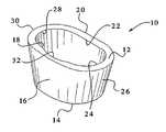
- FIG. 1is a perspective view of a preferred embodiment of a tibial augment of the present invention
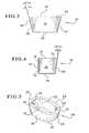
- FIG. 2is a top view of the tibial augment of FIG. 1 ;
- FIG. 3is an anterior view of the tibial augment of FIG. 1 , with the posterior view being identical due to symmetry along the major axis;
- FIG. 4is a lateral view of the augment of FIG. 1 , with the medial view being a mirror image thereof;
- FIG. 5is a perspective view of a tibial augment of a different height than that shown in the FIG. 1 embodiment;
- FIGS. 6A-6Care anterior views of three different stepped versions of the tibial augment of the present invention.
- FIG. 7is a view of a tibia, shown with the damaged proximal bone surface removed and also including a cavity within which a tibial augment of the present invention will be implanted;
- FIG. 8is a view of a tibial augment of the present invention, shown implanted in place below a knee joint prosthesis;
- FIG. 9is a perspective view of a provisional tibial augment of the present invention.
- FIG. 10is a top view of a holder of the present invention, where the holder is intended for use with the provisional of FIG. 9 ;
- FIG. 11is a side view of the holder of FIG. 10 ;
- FIG. 12is a perspective view of a second embodiment of a holder of the present invention.
- FIG. 14is a perspective view of a pusher of the present invention, which pusher is intended to be used to implant the tibial augment;
- FIG. 15is a bottom view of the pusher of FIG. 14 ;
- FIG. 16is a side view of the pusher of FIG. 14 ;
- FIG. 17is a front view of the pusher of FIG. 14 , and an enlarged view of the augment seating portion upon which a tibial augment has been seated;
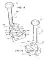
- FIG. 18is a perspective view of a guide and a curved osteotome of the present invention, which are used for making a cavity for the augment;
- FIG. 19is a bottom view of the guide of FIG. 18 ;
- FIG. 20is a side view of the guide of FIG. 18 ;
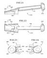
- FIG. 21is a side view of the osteotome of FIG. 18 ;
- FIG. 23is a bottom view of the osteotome of FIG. 18 ;
- FIG. 24is a bottom view of the osteotome of FIG. 25 ;
- FIG. 25is a perspective view of the guide of FIG. 18 , shown with a second osteotome of the present invention.
- FIG. 26is a perspective view of the guide of FIG. 18 , shown with a third osteotome of the present invention.
- FIG. 27is a side view of the osteotome of FIG. 26 ;
- FIG. 28is a rear view of the osteotome of FIG. 26 .
- the tibial augmentis preferably an annular member 10 , and it is preferably made from a tantalum based porous material, such as Trabecular MetalTM.
- Trabecular Meta 1 TMis desirable because it resembles bone and approximates the physical and mechanical properties of bone better than other materials. Use of such a metal enables increased bonding with the adjacent bone by allowing the bone to grow into its highly porous surface.
- the tibial augmentmay also be made of other materials, and it is preferably made of a material that facilitates bony ingrowth.
- the tibial augment 10is anatomically sized and shaped to fill an existing cavitary defect within the proximal human tibia or a cavity prepared in the proximal portion of a human tibia.
- a system of different stock sizes of augmentswould be available, as discussed more fully below, with different sizes being used for different sized tibias.
- two augments of different sizesmay be stacked upon each other if such stacking is necessary to fill the cavity.
- the tibial augment 10includes a proximal surface 12 , a distal surface 14 , an outer anterior surface 16 , an inner anterior surface 18 , an outer posterior surface 20 , an inner posterior surface 22 , an inner lateral surface 24 , an outer lateral surface 26 , an inner medial surface 28 and an outer medial surface 30 .
- the surfaces designated as the medial and lateral surfaceswill be reversed.
- the augmentis symmetric with respect to its lateral and medial sides, such distinctions are irrelevant, and the terms lateral and medial are being used for convenience of description only.
- the outer lateral surface 26is curved to define a continuous surface that connects the outer posterior surface 20 and the outer anterior surface 16 .
- the outer medial surface 30is curved to define a continuous surface that connects the outer posterior surface 20 and the outer anterior surface 16 .
- the outer anterior surface 16is slightly curved and the outer posterior surface 20 is a generally planar surface.
- a majority of the annular member 10is of a substantially uniform thickness, as most readily depicted by the hidden lines of FIGS. 3 and 4 .
- an annular member like annular member 10is made from a metal material that is porous like Trabecular MetalTM, it is understood that the porous metal material spans the entirety of this thickness.
- the major exception to the uniform thicknessis a channel 32 , shown in FIGS. 1 and 2 , which defines a reduced thickness portion.
- the thickness of the majority of the augmentis preferably approximately 5 mm thick, and the thickness of the reduced thickness portion is preferably approximately 3 mm at its narrowest point.
- the preferred embodimentincludes walls of a substantially uniform thickness, with a reduced thickness portion near channel 32 , it is also contemplated that the walls could be tapered, in either direction, between the proximal and distal surfaces.
- the present augment 10is shown and described for use with a stemmed tibial base plate and includes a channel for accommodating the base plate's stem, it is contemplated that the present invention could also be used with other forms of base plates without stems, and therefore the channel could be omitted. Further, it is also contemplated that the inner surfaces of the tibial augment of the present invention could be modified to accommodate other designs of tibial base plates, such as pegged base plate designs.
- both the outer medial surface 30 and the outer lateral surface 26have a distal taper (i.e. downward slope) of between approximately 8 degrees and approximately 30 degrees, with a taper of approximately 19 degrees being preferred.
- Such tapersreplicate the tapers commonly found in corresponding areas of the proximal portions of human tibias. Since the thickness of the annular member 10 is generally uniform from its proximal side to its distal side, the inner medial surface 28 and the inner lateral surface 24 will also have the same taper as the outer lateral and medial surfaces.
- the outer posterior surface 20has a distal taper of less than approximately 17 degrees, with a taper of approximately 12 degrees being preferred.
- the outer anterior surface 16is an essentially normal surface relative to the proximal surface 12 .
- those of the anterior and posterior surfaceswere also chosen to mimic the tapers of the appropriate portions of a human tibia.
- the tapers of the inner posterior and anterior surfaces ( 22 and 18 , respectively)will be the same as those of the corresponding outer posterior and anterior surfaces ( 20 and 16 , respectively).
- the present inventionalso comprises a system of a plurality of differently sized augments that can be held on hand in order to accommodate tibias of different sizes. It is contemplated that three or four different sizes in the anterior/posterior-medial/lateral direction should suffice for most applications.
- the lateral/medial dimensioncould range from about 40 mm to about 80 mm, when measured from its widest point (which is at the proximal surface).
- the lateral/medial dimension of the smallest tibial augment (at its widest point)would be 48 mm for an extra small augment, 52 mm for a small augment, 59 mm for a medium augment and 67 mm for a large augment.
- anterior/posterior dimensioncould range from about 30 mm to about 40 mm, when measured from the widest point in the anterior/posterior direction (which is at the proximal surface).
- approximate minimum dimensions for extra small, small, medium, and large augmentswould be 33 mm, 34 mm, 36 m and 38 mm, respectively.
- two different heights of augmentsshould be available, where the height is measured from the proximal surface 12 to the distal surface 14 .
- a shorter augmentcan be used than that needed where the decay has extended to a greater depth of the bone.
- as much healthy boneshould be preserved as possible.
- two augments of different sizesmay be stacked upon each other. For example, a small augment may be stacked upon an extra small augment; a medium augment may be stacked upon a small augment; or a large augment may be stacked upon a medium augment. Due to the shapes of the outer peripheries of the augments, stacking essentially creates extensions of the outer lateral, medial, posterior and anterior surfaces.
- the tibial augment 10 shown in FIGS. 1 through 3is one example of an augment of the 30 mm height
- the tibial augment 40 shown in FIG. 5is one example of an augment of the 15 mm height.
- the augment 40 of FIG. 5is essentially the same as the augment 10 of FIGS. 1 through 4 , except for the height thereof. Accordingly, the same index numbers have been used in FIG. 5 as those used in FIGS. 1 through 4 .
- augmentsmay be desired.
- six different sizes of augmentare believed to be sufficient—extra small, small, medium and large in a short height (such as 15 mm) and medium and large in a tall height (such as 30 mm).
- a tall heightsuch as 30 mm
- FIGS. 6A through 6Cthree different stepped versions of a tibial augment are shown. More specifically, FIG. 6A shows stepped augment 50 , FIG. 6B shows stepped augment 60 and FIG. 6C shows stepped augment 70 . Since only the distal surface of the stepped augments is different from the augment of FIGS. 1 through 4 , only that portion needs to be discussed. In addition, the same index numbers as those used in FIGS. 1 through 4 will be used for similar features found in FIGS. 6A through 6C .
- FIG. 6Ashows tibial augment 50 , which includes a stepped distal surface 14 a / 14 b with a transition surface 52 therebetween.
- distal surface 14 ais located at a greater distance from the proximal surface 12 than distal surface 14 b .
- the transition surface 52is located approximately midway between the outer medial surface 30 and the outer lateral surface 26 .
- FIG. 6BA second embodiment of a stepped tibial augment is shown in FIG. 6B , as represented by tibial augment 60 .
- distal surface 14 ais located at a greater distance from the proximal surface 12 than distal surface 14 b .
- the main difference between this embodiment and the FIG. 6A embodimentis the location of the transition surface 52 .
- the transition surface 52is located closer to the outer lateral surface 26 than to the outer medial surface 30 .
- FIG. 6Cshows a third embodiment of a stepped tibial augment 70 .
- distal surface 14 ais located at a greater distance from the proximal surface 12 than distal surface 14 b .
- the main difference between this embodiment and the other two embodimentsis the location of the transition surface 52 .
- the transition surface 52is located closer to the outer medial surface 30 than to the outer lateral surface 26 .
- FIGS. 6A through 6Care especially useful where to there has been uneven tibial decay, i.e., where there is more decay on either the lateral side or the medial side than on the other side.
- tibial decayi.e., where there is more decay on either the lateral side or the medial side than on the other side.
- the base of the cavity into which the stepped tibial augment will be implantedwill be stepped to correspond to the stepped distal surface of the augment.
- Such a stepped-base cavityprovides for preservation of more healthy bone on the shallower side, as compared with a flat-based cavity where bone has been removed to a depth equal to the depth of the lowest damaged area of bone.
- Suggested heights for the stepped tibial augments of FIGS. 6A through 6Care 15 mm and 30 mm (as measured from the proximal surface 12 to the distal surfaces 14 b and 14 a , respectively). Of course, other heights are also contemplated as being within the scope of the invention.
- FIG. 7shows an example of a human tibia 80 into which a cavity 82 has been prepared or formed in a proximal portion thereof.
- the cavity 82 of this examplehas a flat base 84 , so it is suitable for tibial augments with flat distal surfaces, such as those depicted in FIGS. 1 through 5 .
- those of ordinary skill in the artshould be able to adapt the flat base 84 into a stepped base using the cavity forming techniques described hereinbelow.
- the tibia 80 of FIG. 7is shown in a state prior to implantation of a tibial augment and a knee joint prosthesis. More specifically, the extreme proximal portion of the tibia 80 has been removed. Normally, most, if not all, of the removed proximal portion will be damaged tibial bone. However, a small amount of healthy bone may also need to be removed at the same time in order to provide a relatively flat surface upon which the flat-bottomed tibial base plate 102 ( FIG. 8 ) can be seated.
- an intramedullary rod 88may be inserted and used to define the relationship between the knee prosthesis stem and the tibial augment.
- FIG. 8An example of a tibial augment 10 that has been implanted into a human tibia is shown in FIG. 8 .
- This figureshows how the tibial augment 10 that is seated within a cavity, such as cavity 82 of FIG. 7 , is positioned directly distal of the stemmed tibial base plate 102 .
- the tibial base plate 102is cemented to the tibial augment 10 .
- the remainder of the components of the knee joint prosthesis 100(the articulating surface 106 , the femoral component 108 , etc.) are all implanted in the customary manner.
- the tibial augments of the present inventioncan be used with other types of knee joint prostheses.
- FIG. 9shows an example of a provisional tibial augment 90 , which is a temporary augment used as a test to ensure that the permanent augment will fit properly within the cavity.
- provisional augmentsshould be made to correspond to every size of tibial augment, including the stepped augments.
- FIGS. 1 through 6CThere are two main differences between the provisional augment 90 and the permanent augments of FIGS. 1 through 6C .
- the provisional augment 90may be made of a material which indicates the bony areas of the provisional so that the surgeon can visualize how the augment fits within the cavity.
- the provisionalmay be made of a transparent or photo-elastic material.
- a suggested material for the provisionalis polyphenylsulfone, although other materials are also contemplated.
- provisional augmentspreferably include a set of grooves 92 / 94 on the inner medial surface 28 and the inner lateral surface 24 . These grooves 92 and 94 extend in the generally lateral/medial direction, and are configured to cooperate with ribs 96 on holder 110 shown in FIG. 10 .
- the holder 110is designed to facilitate insertion and removal of the provisional augment 90 to/from the cavity 82 ( FIG. 7 ) in order to determine that there is a proper fit between the cavity and the provisional augment (and therefore there is necessarily a proper fit with the permanent augment also, since both the provisional and the permanent augment are the same size and shape).
- the holder 110includes two flexible legs 112 that extend in one direction (to the left, as shown in FIGS. 10 and 11 ) to a body portion 114 that is topped with a crown portion 116 . As shown towards the right-hand sides of FIGS. 10 and 11 , each leg 112 connects with a shoulder portion 118 . Each shoulder portion 118 in turn extends into a finger portion 120 , upon which the ribs 96 are situated.
- the lowermost surfaces of the shoulders 118each include a stop surface 122 , which is used to align the holder 110 with the proximal surface 12 of the provisional 90 ( FIG. 9 ) to facilitate the mating of the ribs 96 of the holder 110 with the grooves 92 and 94 of the provisional 90 .
- the holder 110is preferably made of stainless steel, but it is contemplated that it may also be fabricated from plastic.
- a key consideration when selecting materialis that the legs 112 must be flexible enough to be able to be biased inwardly towards each other with light force applied from the surgeon's thumb and forefinger, but they must also be resilient enough to return to their original positions when the force is removed.
- the legs 112 of the holder 110are flexed inwardly by the surgeon, and the fingers 120 are inserted into the interior of the provisional 90 (which is an annular member). Once the stops 122 contact the proximal surface 12 of the provisional, the ribs 96 of the holder should be face to face with the grooves 92 and 94 of the provisional 90 . Pressure on the legs 112 can now be released, and the legs 112 will flex outwardly until the ribs 96 mate with the grooves 92 and 94 .
- the holder 110can be moved (such as by holding the crown portion 116 and/or by the body portion 114 ), and the provisional 90 will remain attached to the holder 110 , for inserting/removing the provisional 90 to/from the cavity 82 ( FIG. 7 ).
- the holder 110can be disengaged from the provisional without affecting the position of the provisional. Thus, once the provisional is seated in the desired position, the legs 112 can be squeezed together, and the holder 110 can be removed without disrupting the position of the provisional.
- the 30 mm height medium-sized provisional (or augment)is essentially a 15 mm height medium-sized provisional (augment) stacked upon a 15 mm height small-sized provisional (augment).
- the 30 mm height large-sized provisional (or augment)is essentially a 15 mm large-sized provisional (augment) stacked upon a 15 mm medium-sized provisional (augment).
- the 30 mm height medium-sized provisionalcan employ the same holder as the 15 mm medium-sized provisional (since they have the same proximal dimensions), and the 30 mm large-sized provisional can employ the same holder as the 15 mm large-sized provisional.
- the number of holdersdoes not need to be increased because the rib spacing on a stepped provisional is the same as that of a similarly sized flat-bottomed provisional.
- the extra small holdercan be used with the extra small stepped provisional, the small holder with the small stepped provisional, the medium holder with the medium stepped provisional, and the large holder with the large stepped provisional.
- Holder 111is adjustable so that it can be used with provisionals of a variety of different sizes, as well as with provisionals other than tibial augment provisionals, such as femoral provisionals.
- Holder 111includes a body portion 113 that serves as a handle and may optionally include a ribbed surface 115 that allows for a more secure grip.
- the body portion 113which defines a longitudinal axis (a vertical axis as shown in FIGS. 12 and 13 ), is connected to a pair of legs 117 .
- legs 117are each preferably L-shaped, and are preferably attached to the lower portion of the body portion 113 by welding (although other attaching means, such as screws, may be used instead).
- the legs 117 and the body portion 113may be formed as a single unit, such as by casting, which will eliminate the need for any attaching means for connecting the legs with the body portion.
- the body portion 113 and the legs 117define a generally fork-shaped component, as shown in FIG. 13 .
- Each of the legs 117includes a finger 119 connected thereto.
- the fingers 119are preferably connected to the legs 117 via an externally threaded shaft 121 .
- the threaded shaft 121is divided in half such that one half is threaded in one direction and the other half is threaded in the opposite direction.
- Each of the fingersincludes an internally threaded aperture 123 that is configured to mate with the associated portion of the threaded shaft 121 .
- each of the fingers 119preferably includes a thickened portion 129 , which serves to increase the contact area between the threaded aperture 123 and the threaded shaft 121 . Thickened portions 129 also provide stops that prevent the fingers 119 from coming too close together.
- each of the legspreferably includes an open-ended slot 127 for receiving the ends of the shaft, which are preferably not threaded.
- a small metal blockis welded to each slot to close its open-end, which serves to maintain the threaded shaft in position, while still allowing rotation of the threaded shaft with respect to the legs.
- other methods of attaching the threaded shaft 121 to the legs 117are also contemplated as being within the scope of the invention.
- a secondary shaft 131is also provided in parallel with the threaded shaft 121 .
- the secondary shaft 131is preferably not threaded, and is provided in order to prevent the fingers 119 from rotating with respect to the legs 117 when the threaded shaft 121 is rotated.
- the fingers 119are connected to the secondary shaft 131 via a pair of apertures 133 (where one aperture extends through each finger), which allows the fingers to slide along, as well as rotate with respect to, the secondary shaft 131 .
- the secondary shaftmay be slightly tapered from the center thereof.
- the center portion 135may be made of full diameter, and extending outwardly therefrom towards the legs 117 , the secondary shaft 131 may include a one degree taper (although tapers of different degrees may also be provided), with the ends seated within apertures 133 preferably being of the same diameter as the center portion 135 .
- the secondary shaft 131is welded in place at the apertures 133 , although other ways of attaching the secondary shaft to the legs may also be used.
- other means of preventing the fingers 119 from rotating with respect to the threaded shaftare also contemplated as being within the scope of the invention.
- the legs and/or the body portionmay include some form of protrusion extending therefrom for preventing rotation of the fingers 119 with respect to the legs 117 , but which still permits the fingers to move sideways (i.e., towards and away from each other) with respect to the legs.
- the upper portions of the fingers 119may be configured to include forks that extend upwardly to straddle the legs 117 and/or the lower portion of the body portion 113 .
- Each of the fingers 119also includes a rib 137 , and they also each preferably include a stop surface 139 .
- the ribs 137 of holder 111are configured to mate with the grooves 92 and 94 of the provisional 90 ( FIG. 9 ) for inserting and removing the provisional to/from the cavity, and the stop surfaces 139 are used to align the holder 111 with the proximal surface 12 of the provisional 90 to facilitate mating the ribs of the holder with the grooves of the provisional.
- the holder 111is preferably made of stainless steel or of another metal, but other materials may be used for all or for only some of the components. For example, plastic may be used for certain parts such as the body portion 113 , the knob 125 and the secondary shaft 131 , while a metal or other different material may be used for the remaining components.
- the spacing of the fingers 119should be able to be adjusted so that the fingers are far enough apart to enable the ribs 137 to engage with the grooves of the largest provisional, as well as to be adjusted to be close enough together for use with the smallest provisional.
- a distance of approximately two inches between the outer surfaces of the fingers 119 when separated at the maximum distance and a distance of approximately three quarters of an inch when separated at the minimum distanceshould be sufficient for most uses.
- these dimensionsare only provided as a suggestion, and other dimensions may also be used.
- the knob 125is rotated to separate the fingers 119 by a distance that is less than the distance that separates the grooves of the provisional being acted upon (such as grooves 92 and 94 of provisional 90 in FIG. 9 ).
- the stop surface 139is positioned upon the proximal surface of the provisional, and the ribs 137 of the holder are aligned with the grooves 92 and 94 of the provisional 90 ( FIG. 9 ).
- the knob 125is again rotated to make the ribs 137 engage the grooves 92 and 92 , and the provisional 90 is inserted into the cavity 82 ( FIG. 7 ).
- the holder 111can be disengaged from the provisional 90 by rotating the knob 125 to bring the fingers 119 closer together, separating the ribs 137 from the grooves 92 and 94 .
- One important feature of the holder 111is that is allows the ribs to be disengaged from the grooves without significantly altering the location of the provisional within the cavity.
- the preferred embodiments of the provisional and holder combinationhave been shown and described with grooves on the inner lateral and medial surfaces. However, it is also contemplated that the grooves could be placed on the inner anterior and posterior surfaces, and that the spacing of the fingers on the holder could be adjusted accordingly. Further, detents could be substituted for the grooves, and a spring loaded holder for mating with the detents could also be used.
- the provisionalmay include a threaded circular holder into which a threaded handle member can be inserted and removed.
- FIGS. 14 through 17show an example of a tibial augment pusher 130 , which is used to seat a tibial augment within the cavity of the proximal portion of the tibia.
- the pusher 130(or one of the holders) may also be used in conjunction with the provisional tibial augment as a tamp.
- the voidcould be filled with morselized bone and the provisional tibial augment (in combination with a holder or pusher) could be used to tamp the morselized bone into place.
- the pusher 130includes a handle portion 132 and an augment seating portion 134 .
- the augment seating portion 134is further divided into a head portion 136 and a platform portion 138 .
- the head portion 136is preferably shaped to mimic the interior surfaces of the tibial augment 10 ( FIG. 1 ), except the head portion 136 is slightly smaller than the corresponding surfaces of the tibial augment 10 associated therewith, which permits the head portion 136 to be easily seated within (and easily withdrawn from) the tibial augment 10 . More specifically, there is preferably approximately 0.030 inches (0.762 mm) clearance between the outer surface of the head portion 136 and the inner surfaces of the tibial augment 10 , as represented by distance “X” in FIG.
- FIG. 17which includes (in the main view) a front view of pusher 130 and a magnified view of part of the head portion 136 of the same pusher, but with a tibial augment 10 seated thereon. That is, the magnified view of FIG. 17 shows the head portion 136 in hidden lines to represent that the head portion is hidden behind the augment 10 , with the inner surface of the augment (also in hidden lines) spaced from the outer surface of the head portion 136 by distance “X.”
- the proximal surface 12 of the augment 10contacts the planar surface 140 of the platform portion 138 , which provides a surface from which the surgeon can apply light pressure to the augment 10 to align, locate, and to seat it within the cavity 82 ( FIG. 7 ).
- the planar surface 140is provided upon the platform portion 138 at the interface between the platform portion 138 and the head portion 136 .
- the shape of the head portion 136mimics the shape of the interior surfaces of the augment 10 , it follows that the head portion 136 should have a taper of approximately 19 degrees (+/ ⁇ 3 degrees) at the surface that corresponds to the inner medial and lateral surfaces (as shown in FIG. 17 ), and that it should have a taper of approximately 12 degrees (+/ ⁇ 3 degrees) at the surface that corresponds to the inner posterior surface (as shown in FIG. 16 ). Further, as also shown in FIG. 16 , the surface of the head portion 136 that corresponds to the inner anterior surface is not tapered, but is instead substantially perpendicular to the platform portion 138 .
- the pusher 130In order to properly orient a tibial augment 10 within a cavity, the pusher 130 must have a head portion 136 that is appropriately shaped, as discussed above, and the head portion must also be appropriately sized.
- a number of pushersmay be provided for the set of augments. For example, if there are four sizes of augments (extra small, small, medium and large), with two heights available (15 mm and 30 mm) for the medium and the large sizes only, then there is a total of six differently sized augments.
- each pusher 130is preferably made with an aluminum handle portion 132 and an acetyl seating portion 134 .
- the seating portioncould be made from various polymers or metals and the handle portion could be made of a different metal or from plastic.
- FIGS. 18 through 28a guide and several associated osteotomes that are all used to create a cavity in the tibia are shown and will be described next.
- the cavity formed in the tibia(such as cavity 82 of FIG. 7 ) must be carefully created so that the tibial augment fits as precisely as possible.
- the present inventionincludes tools and a method of creating a cavity of the proper size and shape. Although only one method of creating the cavity will be shown and described, other methods may also be used as a supplement to or in place of the method described.
- a rasp techniquemay be used to either create the cavity or to make fine adjustments to a cavity created by another method.
- a rasp shaped like a tibial augment(with a rasp-like outer surface and a handle) is used to remove the bone and form the cavity (or to make fine adjustments to the shape of the cavity).
- FIG. 18shows a preferred embodiment of a guide 142 with a first curved osteotome 144 inserted into a portion of a slot 146 formed within the guide 142 .
- FIG. 25shows a second curved osteotome 148 (inserted into the guide 142 ), and
- FIG. 26shows a straight osteotome 150 (also inserted into the guide 142 ).
- all three different osteotomes( 144 , 148 and 150 ) are required to form the cavity 82 ( FIG. 7 ) because of the configuration of the slot 146 , which is specifically configured to properly orient the osteotomes to create a cavity that corresponds to the tibial augment being implanted therein.
- the osteotomes 144 , 148 and 150are preferably made of stainless steel, although other materials are also contemplated.
- the osteotomes and guidesare preferably configured in a variety of different sizes.
- these four sets of osteotomes and four guidescan be used to create a cavity in the tibia for any of the 15 mm, 30 mm or stepped augments of the preferred embodiment.
- the first curved osteotome 144includes a handle 152 with a crown 154 at the top end thereof.
- the curved osteotome 144also includes a cutting portion 156 attached to the handle 152 , and the cutting portion includes a tapered edge 158 at its far end and a plurality of first (or distal) stops 160 for hindering the cutting portion from extending into the slot 146 of the guide 142 past a predetermined distance.
- the cutting portion 156 of the osteotome 144also includes at least one second (or proximal) stop 162 .
- the slot 146 in the guide 142preferably includes a plurality of cutouts 147 ( FIG. 19 ), which allow the distal stops 160 to pass through in order to use the proximal stop 162 .
- the proximal stop 162is placed at a greater distance from the tapered edge 158 than the distal stops 160 , as can be seen in FIGS. 21 and 22 .
- the use of such staggered stopsallows a single osteotome to be used to make two different cavities of two different depths, depending upon which stop is used and also depending upon which size guide is used.
- tibial augmentsare provided in two different heights (such as 15 mm and 30 mm)
- accommodationsmust be made to provide cavities of two different depths (15 mm and 30 mm) so that the depth of the cavity coincides with the height of the tibial augment being placed therein.
- the set of osteotomesis inserted into the same sized guide (e.g., the set of small osteotomes is used with the small guide, etc.) whereby the exterior stops 160 contact a planar top surface 143 of the guide, hindering the cutting portion 156 from extending further into the guide, and accordingly hindering further extension into the bone.
- the set of osteotomesBy inserting the set of osteotomes into the same sized guide, distal stops 160 do not mate with cutouts 147 , and therefore stops 160 do not pass through cutouts 147 .
- the same set of osteotomesare inserted into the incrementally larger guide (e.g.
- the small osteotomesare used with the medium guide), whereby the distal stops 160 pass through cutouts 147 and the proximal stop 162 contacts the planar top surface 143 of the guide, hindering the cutting portion 156 from extending further into the guide, and accordingly hindering further extension into the bone.
- the distal and proximal stops of the other osteotomesfunction in a similar manner. Although in the examples provided the distal and proximal stops have been shown and described as being on the radially exterior sides of the osteotomes, some or all of the stops may be provided on the radially interior sides of the osteotomes.
- the cutouts 147 on the guide 142would have to be changed to be on the radially interior side of the slot 146 .
- the distal stopsare provided on the radially exterior side of the osteotome and the proximal stops are provided on the radially interior side (or vice versa)
- the cutouts 17could be omitted, if desired, as long as the slot was made wide enough to accept the cutting portion 156 including the stops.
- FIG. 25shows an example of a second curved osteotome 148 .
- the second curved osteotome 148is very similar to the first curved osteotome 144 in that it also includes a handle 164 , a crown 166 , and a cutting portion 168 with a tapered edge 170 and a plurality of distal stops 172 , as well as at least one proximal stop 174 .
- first curved osteotome 144 and the second curved osteotome 148are identical to each other, but are just shown in different orientations, in actuality, they are mirror images of each other. More specifically, the front cutting area 176 of the first curved osteotome 144 and the front cutting area 178 of the second curved osteotome 148 each have no inclination, which corresponds to the outer anterior surface 16 of the tibial augment 10 ( FIG. 4 ) that also has no incline. Similarly, since the outer posterior surface 20 preferably has an incline of approximately 12 degrees (although inclines within the range of between about 0 to about 17 degrees may also be used), as shown in FIG.
- the posterior cutting area 184 of the first curved osteotome 144 and the posterior cutting area 186 of the second curved osteotome 148is also provided with an incline of 12 degrees (or a corresponding incline within the range of about 0 to about 17 degrees, depending upon the exact degree of incline provided to the anterior surface of the tibial augment).
- the outer medial surface 30 and the outer lateral surface 26 of the tibial augment 10are preferably inclined at 19 degrees (or within the range of between about 8 to about 30 degrees), as shown in FIG.
- FIGS. 23 and 24also show how cutting portion 156 is a mirror image of cutting portion 168 . Accordingly, the second curved osteotome 148 is not interchangeable with the first curved osteotome 144 .
- FIGS. 26 through 28show straight osteotome 150 .
- the straight osteotomeincludes a handle 188 , a crown 190 , and a cutting portion 192 with a tapered edge 194 , distal stops 196 , and at least one proximal stop 198 .
- the cutting portion 192is preferably inclined with respect to the handle. This degree of incline corresponds to the degree of incline of the outer posterior surface 20 of the tibial augment 10 ( FIG. 4 ). Thus, in the preferred embodiment, there is an incline of approximately 12 degrees.
- inclines of between approximately 0 degrees and approximately 17 degreesare also contemplated as being within the scope of the invention, as well as other degrees of incline.
- the orientation of the cutting portion 192 with respect to the handle 188 of this osteotome, as well as the other osteotomes,is intended to allow for the proper cutting angle when the handle is held perpendicular to the tibial surface within which the cavity 82 ( FIG. 7 ) has been formed.
- the guide 142is also provided so that the proper cutting orientation of the osteotomes is maintained, which thereby aids in making a cavity with sidewalls of inclines that correspond to the inclines on the outer surfaces of the tibial augment.
- the guide 142includes a slot 146 for guiding the cutting portions ( 156 , 168 , 192 ) of the osteotomes ( 144 , 148 , 150 ).
- Each portion of the slot 146is made with a particular incline that matches the incline of the corresponding outer surface of the tibial augment associated therewith.
- the slot's lateral portion 200 and the slot's medial portion 202are inclined, respectively, to match the slopes of the outer lateral surface 26 and the outer medial surface 30 of the tibial augment 10 , which in the preferred embodiment is a 19 degree incline.
- the slot's posterior portion 204 and its anterior portion 206are also configured to correspond of the incline of, respectively, the outer posterior surface 20 and the outer anterior surface 16 of the tibial augment 10 .
- the slot's posterior portion 204will be inclined at approximately 12 degrees and the slot's anterior portion 206 will have no incline.
- the guide 142also includes a securing arrangement that is used to secure the guide to the bone within which the cavity is being formed.
- the securing arrangementincludes an aperture 208 that is configured to receive the intramedullary rod 88 ( FIG. 7 ), which serves as both a reference point for the guide and as the stable member that the guide is secured upon.
- the securing arrangementalso includes a threaded hole 210 ( FIG. 18 ) that is configured to receive a setscrew 212 ( FIG. 19 ), which is comprised of a head 214 and a threaded shaft 216 .
- the setscrewcould also be replaced with a thumbscrew or the head could be replaced with a lever or small handle to facilitate tightening without the need for a screwdriver.
- the threaded hole 210is preferably made within a collar 218 , which allows for additional length of the setscrew 212 , and also allows for also easier access to the head of the setscrew, which may be necessary, especially if a thumbscrew of other similar component is used in place of the setscrew.
- the slot 146 of the guide 142is not annular, but instead includes a gap near its anterior portion 206 , as best shown in FIG. 19 .
- This gapis where the threaded shaft 216 of the setscrew extends through the guide. If this gap in the slot 146 were not present, there is a chance that the threaded shaft 216 of the setscrew could accidentally be damaged if an osteotome were inserted into the slot at this area. Damaging the setscrew could result in misalignment of the guide with respect to the bone, or it could make it difficult to remove the guide from the intramedullary rod 88 .
- the same sized guideis used, but the set of osteotomes for the next smaller size is used.
- the medium guideis used along with the small set of osteotomes.
- the guide that is the same size as the augment being inserted(extra small, small, medium or large) will always be used.
- the set of osteotomes of one size smaller than the augmentare used, otherwise (for 15 mm depth cavities), the set of osteotomes of the same size as the augment are used.
- the medium sized guide 142is affixed to the intramedullary rod 88 .
- medium osteotome 144is inserted into the correspondingly sized medium guide, whereby the distal stop 160 contacts the planar top surface 143 of the guide, hindering the cutting portion 156 from extending further into the guide, past the desired 15 mm depth.
- the other medium osteotomesare also used in the same manner, with the stops operating in a similar manner to create a 15 mm depth cavity for the 15 mm medium augment.
- the set of small osteotomesi.e., the osteotomes of one incremental size smaller than the augment
- the distal stop 160passes through the medium guide cutout 147 , allowing the cutting portion 156 of the osteotome to extend further into the bone until the proximal stop 162 contacts the planar top surface 143 of the guide.
- the contact of the proximal stop 162 with the top planar surfacehinders the cutting portion from extending further into the guide than the desired 30 mm, and accordingly hinders further extension into the bone.
- the distal stop 160contacts the planar top surface 143 of the guide, hindering the cutting portion of the 156 from extending further into the guide so that a 15 mm deep cavity can be created).
- the distal and proximal stops of the other small osteotomesfunction in a similar manner, and a 30 mm depth cavity for the medium augment is created by using all three small osteotomes with the medium guide.
- an appropriately sized guide 142 and an appropriately sized set of osteotomesare selected.
- the aperture 208 of the guide 142is slid over the intramedullary rod 88 , and the guide 142 is secured in place by tightening the setscrew 212 .
- the aperture 208is preferably triangular, as best shown in FIG. 19 , which allows for the intramedullary rod 88 to have an increasingly secure fit as the setscrew is tightened because of the way the rod is seated at the apex of the triangle.
- one of the appropriately sized osteotomessuch as the first curved osteotome 144 , is inserted into the appropriate position of the slot 146 . More specifically, the first curved osteotome 144 is inserted into portion 200 of the slot 146 . It should be noted that the osteotomes may be used in any desired order.
- the desired depth of cavityis formed by using the appropriate combination of a particularly sized set of osteotomes with an appropriately sized guide, whereby either proximal stops 198 or distal stops 196 are utilized to result in a cut of an appropriate depth.
- cuts of one depthmay be made at one area of the cavity and cuts of another depth may be made at another area in order to form an appropriate cavity with a stepped bottom to accommodate the stepped distal surface 14 a / 14 b of FIGS. 6A through 6C .
- one of the other osteotomessuch as the straight osteotome 150 ( FIGS. 26-28 ) is inserted into the appropriate portion of the slot. As shown in FIG. 26 , the straight osteotome 150 is inserted into the slot's posterior portion 204 (best seen in FIG. 19 ). As described above, the appropriate stop, or stops, (either proximal stop 198 or distal stops 196 ) is/are utilized to result in a cut of the appropriate depth.
- the bone to be removedshould be cut to the desired depth, and it merely needs to be taken from the site to form the cavity 82 ( FIG. 7 ). If necessary, an additional cut may need to be made with the straight osteotome 150 , or one of the other osteotomes, at the area below the gap in the slot 146 , between the two edges of the anterior portion 206 ( FIG. 19 ). However, the decayed bone at that area may simply fall from the peripheral bone without requiring an additional cut. Once the bone is completely removed from within the cut area formed by the osteotomes, a cavity that corresponds to the tibial augment being inserted therein should result.
- the fitAfter the fit is adequately tested with the provisional 90 , it can be removed by using the provisional holder 110 or 111 in the manner previously described. Then, the permanent tibial augment, such as augment 10 of FIG. 1 , is inserted using the pusher 130 ( FIG. 12 ). After properly seating the augment within the cavity, cement is applied to the proximal surface 12 of the augment, and the stemmed tibial base plate 102 ( FIG. 8 ) is attached to the augment and to the peripheral bone remaining around the cavity. Then, the remainder of the knee joint prosthesis 100 is attached using any desired method, and the surgical procedure continues in the customary manner.
- the permanent tibial augmentsuch as augment 10 of FIG. 1
- the pusher 130FIG. 12
- cementAfter properly seating the augment within the cavity, cement is applied to the proximal surface 12 of the augment, and the stemmed tibial base plate 102 ( FIG. 8 ) is attached to the augment and to the peripheral bone remaining around the cavity.
Landscapes
- Health & Medical Sciences (AREA)
- Orthopedic Medicine & Surgery (AREA)
- Life Sciences & Earth Sciences (AREA)
- Transplantation (AREA)
- Oral & Maxillofacial Surgery (AREA)
- Public Health (AREA)
- Engineering & Computer Science (AREA)
- Biomedical Technology (AREA)
- Heart & Thoracic Surgery (AREA)
- Veterinary Medicine (AREA)
- Animal Behavior & Ethology (AREA)
- General Health & Medical Sciences (AREA)
- Cardiology (AREA)
- Vascular Medicine (AREA)
- Surgery (AREA)
- Physical Education & Sports Medicine (AREA)
- Molecular Biology (AREA)
- Medical Informatics (AREA)
- Nuclear Medicine, Radiotherapy & Molecular Imaging (AREA)
- Dentistry (AREA)
- Prostheses (AREA)
Abstract
Description
Claims (34)
Priority Applications (4)
| Application Number | Priority Date | Filing Date | Title |
|---|---|---|---|
| US12/886,297US8506645B2 (en) | 2001-08-27 | 2010-09-20 | Tibial augments for use with knee joint prostheses |
| US13/944,441US9265614B2 (en) | 2001-08-27 | 2013-07-17 | Method of implanting the tibial augment |
| US14/936,929US9907664B2 (en) | 2001-08-27 | 2015-11-10 | Methods for augmenting a tibial component of a knee joint prosthesis |
| US15/839,363US20180098856A1 (en) | 2001-08-27 | 2017-12-12 | Tibial augments for use with knee joint prostheses, method of implanting the tibial augment, and associated tools |
Applications Claiming Priority (4)
| Application Number | Priority Date | Filing Date | Title |
|---|---|---|---|
| US31514801P | 2001-08-27 | 2001-08-27 | |
| US10/225,774US20030065397A1 (en) | 2001-08-27 | 2002-08-22 | Prosthetic implant support structure |
| US10/780,378US20040162619A1 (en) | 2001-08-27 | 2004-02-17 | Tibial augments for use with knee joint prostheses, method of implanting the tibial augment, and associated tools |
| US12/886,297US8506645B2 (en) | 2001-08-27 | 2010-09-20 | Tibial augments for use with knee joint prostheses |
Related Parent Applications (1)
| Application Number | Title | Priority Date | Filing Date |
|---|---|---|---|
| US10/780,378ContinuationUS20040162619A1 (en) | 2001-08-27 | 2004-02-17 | Tibial augments for use with knee joint prostheses, method of implanting the tibial augment, and associated tools |
Related Child Applications (1)
| Application Number | Title | Priority Date | Filing Date |
|---|---|---|---|
| US13/944,441ContinuationUS9265614B2 (en) | 2001-08-27 | 2013-07-17 | Method of implanting the tibial augment |
Publications (2)
| Publication Number | Publication Date |
|---|---|
| US20110009974A1 US20110009974A1 (en) | 2011-01-13 |
| US8506645B2true US8506645B2 (en) | 2013-08-13 |
Family
ID=36648366
Family Applications (5)
| Application Number | Title | Priority Date | Filing Date |
|---|---|---|---|
| US10/780,378AbandonedUS20040162619A1 (en) | 2001-08-27 | 2004-02-17 | Tibial augments for use with knee joint prostheses, method of implanting the tibial augment, and associated tools |
| US12/886,297Expired - Fee RelatedUS8506645B2 (en) | 2001-08-27 | 2010-09-20 | Tibial augments for use with knee joint prostheses |
| US13/944,441Expired - Fee RelatedUS9265614B2 (en) | 2001-08-27 | 2013-07-17 | Method of implanting the tibial augment |
| US14/936,929Expired - LifetimeUS9907664B2 (en) | 2001-08-27 | 2015-11-10 | Methods for augmenting a tibial component of a knee joint prosthesis |
| US15/839,363AbandonedUS20180098856A1 (en) | 2001-08-27 | 2017-12-12 | Tibial augments for use with knee joint prostheses, method of implanting the tibial augment, and associated tools |
Family Applications Before (1)
| Application Number | Title | Priority Date | Filing Date |
|---|---|---|---|
| US10/780,378AbandonedUS20040162619A1 (en) | 2001-08-27 | 2004-02-17 | Tibial augments for use with knee joint prostheses, method of implanting the tibial augment, and associated tools |
Family Applications After (3)
| Application Number | Title | Priority Date | Filing Date |
|---|---|---|---|
| US13/944,441Expired - Fee RelatedUS9265614B2 (en) | 2001-08-27 | 2013-07-17 | Method of implanting the tibial augment |
| US14/936,929Expired - LifetimeUS9907664B2 (en) | 2001-08-27 | 2015-11-10 | Methods for augmenting a tibial component of a knee joint prosthesis |
| US15/839,363AbandonedUS20180098856A1 (en) | 2001-08-27 | 2017-12-12 | Tibial augments for use with knee joint prostheses, method of implanting the tibial augment, and associated tools |
Country Status (1)
| Country | Link |
|---|---|
| US (5) | US20040162619A1 (en) |
Cited By (36)
| Publication number | Priority date | Publication date | Assignee | Title |
|---|---|---|---|---|
| US20070088443A1 (en)* | 2001-08-27 | 2007-04-19 | Hanssen Arlen D | Prosthetic implant support structure |
| US20140257293A1 (en)* | 2013-03-08 | 2014-09-11 | Stryker Corporation | Bone pads |
| US9011444B2 (en) | 2011-12-09 | 2015-04-21 | Howmedica Osteonics Corp. | Surgical reaming instrument for shaping a bone cavity |
| US9044326B2 (en) | 2001-08-27 | 2015-06-02 | Zimmer, Inc. | Femoral augments for use with knee joint prosthesis |
| WO2015145348A1 (en) | 2014-03-27 | 2015-10-01 | Medacta International Sa | Multi-layered prosthetic element |
| US9149282B2 (en) | 2011-12-30 | 2015-10-06 | Howmedica Osteonics Corp. | Systems and methods for preparing bone voids to receive a prosthesis |
| US9265614B2 (en) | 2001-08-27 | 2016-02-23 | Zimmer, Inc. | Method of implanting the tibial augment |
| US9526513B2 (en) | 2013-03-13 | 2016-12-27 | Howmedica Osteonics Corp. | Void filling joint prosthesis and associated instruments |
| WO2017005513A2 (en) | 2015-07-09 | 2017-01-12 | Waldemar Link Gmbh & Co. Kg | Hollow sleeve augment device and tool |
| WO2017005512A1 (en) | 2015-07-09 | 2017-01-12 | Waldemar Link Gmbh & Co. Kg | Sleeve augment device for an articulated joint |
| US10085804B2 (en) | 2009-02-24 | 2018-10-02 | Mako Surgical Corp. | Prosthetic device, method of planning bone removal for implantation of prosthetic device, and robotic system |
| US10149763B2 (en) | 2015-01-12 | 2018-12-11 | Howmedica Osteonics Corp. | Multipurpose void filling prosthesis |
| US10363051B2 (en) | 2015-06-30 | 2019-07-30 | DePuy Synthes Products, Inc. | Method and orthopaedic surgical instrument system for surgically preparing a patient's bone |
| US10517736B2 (en) | 2012-03-27 | 2019-12-31 | DePuy Synthes Products, Inc. | Glenoid defect-filling component |
| USD901014S1 (en) | 2019-08-12 | 2020-11-03 | Ortho Development Corporation | Porous implant |
| USD901013S1 (en) | 2019-08-12 | 2020-11-03 | Ortho Development Corporation | Porous implant |
| USD901012S1 (en) | 2019-08-12 | 2020-11-03 | Ortho Development Corporation | Porous implant |
| US11141276B2 (en) | 2017-01-20 | 2021-10-12 | Biomet Manufacturing, Llc | Modular augment component |
| KR20220063831A (en) | 2020-11-10 | 2022-05-18 | 주식회사 코렌텍 | Modular Augment |
| US11439469B2 (en) | 2018-06-19 | 2022-09-13 | Howmedica Osteonics Corp. | Virtual guidance for orthopedic surgical procedures |
| US11498124B1 (en) | 2019-11-25 | 2022-11-15 | Ortho Development Corporation | Method for sintering porous structures from powder using additive manufacturing |
| US11565021B1 (en) | 2019-08-12 | 2023-01-31 | Ortho Development Corporation | Composite structure porous implant for replacing bone stock |
| US11589923B2 (en) | 2017-03-07 | 2023-02-28 | Imascap Sas | Computer modeling procedures for surgical simulation and planning |
| EP4147678A1 (en) | 2021-09-10 | 2023-03-15 | Heraeus Medical GmbH | Augmentation device and augmentation system |
| US11633294B2 (en) | 2019-12-09 | 2023-04-25 | Depuy Ireland Unlimited Company | Orthopaedic surgical instrument system having an anterior-loading tibial bearing trial and associated surgical method of using the same |
| US11660199B2 (en) | 2020-01-29 | 2023-05-30 | Encore Medical, L.P. | Modular knee augment cones |
| EP4226897A1 (en) | 2022-02-11 | 2023-08-16 | Heraeus Medical GmbH | Augmentation device |
| EP4268771A1 (en) | 2022-04-25 | 2023-11-01 | Heraeus Medical GmbH | Augmentation device and method for adjusting an augmentation device |
| US11850158B2 (en) | 2020-05-26 | 2023-12-26 | Howmedica Osteonics Corp. | Orthopedic surgical implant device with porous material and fluid channels for cleaning the porous material |
| US11944392B2 (en) | 2016-07-15 | 2024-04-02 | Mako Surgical Corp. | Systems and methods for guiding a revision procedure |
| US12045943B2 (en) | 2019-08-16 | 2024-07-23 | Howmedica Osteonics Corp. | Pre-operative planning of surgical revision procedures for orthopedic joints |
| US12042341B2 (en) | 2020-05-06 | 2024-07-23 | Howmedica Osteonics Corp. | Registration marker with anti-rotation base for orthopedic surgical procedures |
| DE102023131784A1 (en)* | 2023-11-15 | 2025-05-15 | Aesculap Ag | Cone and cone set |
| US12370061B2 (en) | 2019-08-29 | 2025-07-29 | Mako Surgical Corp. | Robotic surgery system for augmented arthroplasty procedures |
| US12403010B2 (en) | 2020-12-01 | 2025-09-02 | Encore Medical, Lp | Knee replacement implant having stackable spacers |
| US12434302B2 (en) | 2019-11-25 | 2025-10-07 | Ortho Development Corporation | Method for manufacturing porous structures using additive manufacturing |
Families Citing this family (161)
| Publication number | Priority date | Publication date | Assignee | Title |
|---|---|---|---|---|
| US7497874B1 (en) | 2001-02-23 | 2009-03-03 | Biomet Manufacturing Corp. | Knee joint prosthesis |
| US20020120340A1 (en) | 2001-02-23 | 2002-08-29 | Metzger Robert G. | Knee joint prosthesis |
| US7935118B2 (en)* | 2002-06-21 | 2011-05-03 | Depuy Products, Inc. | Prosthesis removal cutting guide, cutting tool and method |
| US20030236522A1 (en) | 2002-06-21 | 2003-12-25 | Jack Long | Prosthesis cavity cutting guide, cutting tool and method |
| USD684693S1 (en) | 2002-08-22 | 2013-06-18 | Zimmer, Inc. | Prosthetic implant support structure |
| US7927335B2 (en) | 2004-09-27 | 2011-04-19 | Depuy Products, Inc. | Instrument for preparing an implant support surface and associated method |
| US7922769B2 (en)* | 2004-09-27 | 2011-04-12 | Depuy Products, Inc. | Modular glenoid prosthesis and associated method |
| US7892287B2 (en)* | 2004-09-27 | 2011-02-22 | Depuy Products, Inc. | Glenoid augment and associated method |
| US20060074353A1 (en)* | 2004-09-27 | 2006-04-06 | Deffenbaugh Daren L | Glenoid instrumentation and associated method |
| US7998217B1 (en) | 2005-02-02 | 2011-08-16 | Biomet Manufacturing Corp. | Modular offset stem implants |
| WO2007004055A1 (en)* | 2005-06-03 | 2007-01-11 | Laurent Lafosse | Instrument for use in a joint replacement procedure |
| CA2610799C (en)* | 2005-06-03 | 2014-08-05 | Depuy Ireland Limited | Instrument for use in a joint replacement procedure |
| EP1885295B1 (en)* | 2005-06-03 | 2013-12-11 | DePuy (Ireland) | Instrument for use in a joint replacement procedure |
| US7618422B2 (en)* | 2005-11-07 | 2009-11-17 | Howmedica Osteonics Corp. | Tibial augmentation guide |
| US8092465B2 (en) | 2006-06-09 | 2012-01-10 | Biomet Manufacturing Corp. | Patient specific knee alignment guide and associated method |
| US9339278B2 (en) | 2006-02-27 | 2016-05-17 | Biomet Manufacturing, Llc | Patient-specific acetabular guides and associated instruments |
| US8133234B2 (en) | 2006-02-27 | 2012-03-13 | Biomet Manufacturing Corp. | Patient specific acetabular guide and method |
| US8591516B2 (en) | 2006-02-27 | 2013-11-26 | Biomet Manufacturing, Llc | Patient-specific orthopedic instruments |
| US8608748B2 (en) | 2006-02-27 | 2013-12-17 | Biomet Manufacturing, Llc | Patient specific guides |
| US8603180B2 (en) | 2006-02-27 | 2013-12-10 | Biomet Manufacturing, Llc | Patient-specific acetabular alignment guides |
| US8864769B2 (en) | 2006-02-27 | 2014-10-21 | Biomet Manufacturing, Llc | Alignment guides with patient-specific anchoring elements |
| US8858561B2 (en) | 2006-06-09 | 2014-10-14 | Blomet Manufacturing, LLC | Patient-specific alignment guide |
| US8298237B2 (en) | 2006-06-09 | 2012-10-30 | Biomet Manufacturing Corp. | Patient-specific alignment guide for multiple incisions |
| US9345548B2 (en) | 2006-02-27 | 2016-05-24 | Biomet Manufacturing, Llc | Patient-specific pre-operative planning |
| US9113971B2 (en) | 2006-02-27 | 2015-08-25 | Biomet Manufacturing, Llc | Femoral acetabular impingement guide |
| US9289253B2 (en) | 2006-02-27 | 2016-03-22 | Biomet Manufacturing, Llc | Patient-specific shoulder guide |
| US10278711B2 (en) | 2006-02-27 | 2019-05-07 | Biomet Manufacturing, Llc | Patient-specific femoral guide |
| US9918740B2 (en) | 2006-02-27 | 2018-03-20 | Biomet Manufacturing, Llc | Backup surgical instrument system and method |
| US20150335438A1 (en) | 2006-02-27 | 2015-11-26 | Biomet Manufacturing, Llc. | Patient-specific augments |
| US8377066B2 (en) | 2006-02-27 | 2013-02-19 | Biomet Manufacturing Corp. | Patient-specific elbow guides and associated methods |
| US8608749B2 (en) | 2006-02-27 | 2013-12-17 | Biomet Manufacturing, Llc | Patient-specific acetabular guides and associated instruments |
| US8535387B2 (en) | 2006-02-27 | 2013-09-17 | Biomet Manufacturing, Llc | Patient-specific tools and implants |
| US7967868B2 (en) | 2007-04-17 | 2011-06-28 | Biomet Manufacturing Corp. | Patient-modified implant and associated method |
| US9173661B2 (en) | 2006-02-27 | 2015-11-03 | Biomet Manufacturing, Llc | Patient specific alignment guide with cutting surface and laser indicator |
| US8568487B2 (en) | 2006-02-27 | 2013-10-29 | Biomet Manufacturing, Llc | Patient-specific hip joint devices |
| US9907659B2 (en) | 2007-04-17 | 2018-03-06 | Biomet Manufacturing, Llc | Method and apparatus for manufacturing an implant |
| US8282646B2 (en) | 2006-02-27 | 2012-10-09 | Biomet Manufacturing Corp. | Patient specific knee alignment guide and associated method |
| US8241293B2 (en) | 2006-02-27 | 2012-08-14 | Biomet Manufacturing Corp. | Patient specific high tibia osteotomy |
| US8473305B2 (en) | 2007-04-17 | 2013-06-25 | Biomet Manufacturing Corp. | Method and apparatus for manufacturing an implant |
| US8070752B2 (en) | 2006-02-27 | 2011-12-06 | Biomet Manufacturing Corp. | Patient specific alignment guide and inter-operative adjustment |
| US8407067B2 (en) | 2007-04-17 | 2013-03-26 | Biomet Manufacturing Corp. | Method and apparatus for manufacturing an implant |
| US9795399B2 (en) | 2006-06-09 | 2017-10-24 | Biomet Manufacturing, Llc | Patient-specific knee alignment guide and associated method |
| US7842093B2 (en)* | 2006-07-18 | 2010-11-30 | Biomet Manufacturing Corp. | Method and apparatus for a knee implant |
| US8163028B2 (en) | 2007-01-10 | 2012-04-24 | Biomet Manufacturing Corp. | Knee joint prosthesis system and method for implantation |
| US8562616B2 (en) | 2007-10-10 | 2013-10-22 | Biomet Manufacturing, Llc | Knee joint prosthesis system and method for implantation |
| JP5448842B2 (en) | 2007-01-10 | 2014-03-19 | バイオメト マニファクチャリング コーポレイション | Knee joint prosthesis system and implantation method |
| US8328873B2 (en) | 2007-01-10 | 2012-12-11 | Biomet Manufacturing Corp. | Knee joint prosthesis system and method for implantation |
| US8187280B2 (en) | 2007-10-10 | 2012-05-29 | Biomet Manufacturing Corp. | Knee joint prosthesis system and method for implantation |
| US20080172054A1 (en)* | 2007-01-16 | 2008-07-17 | Zimmer Technology, Inc. | Orthopedic device for securing to tissue |
| US20080255573A1 (en)* | 2007-04-10 | 2008-10-16 | Zimmer, Inc. | Surgical laser trajectory instrument |
| US8715359B2 (en)* | 2009-10-30 | 2014-05-06 | Depuy (Ireland) | Prosthesis for cemented fixation and method for making the prosthesis |
| US8632600B2 (en)* | 2007-09-25 | 2014-01-21 | Depuy (Ireland) | Prosthesis with modular extensions |
| US8265949B2 (en) | 2007-09-27 | 2012-09-11 | Depuy Products, Inc. | Customized patient surgical plan |
| US9204967B2 (en) | 2007-09-28 | 2015-12-08 | Depuy (Ireland) | Fixed-bearing knee prosthesis having interchangeable components |
| EP2194889B1 (en) | 2007-09-30 | 2015-09-23 | DePuy Products, Inc. | Customized patient-specific orthopaedic surgical instrumentation |
| US8357111B2 (en) | 2007-09-30 | 2013-01-22 | Depuy Products, Inc. | Method and system for designing patient-specific orthopaedic surgical instruments |
| US8871142B2 (en) | 2008-05-22 | 2014-10-28 | DePuy Synthes Products, LLC | Implants with roughened surfaces |
| EP2130518B1 (en) | 2008-06-03 | 2013-05-15 | DePuy Products, Inc. | Porous titanium femoral sleeves |
| US20090299375A1 (en)* | 2008-06-03 | 2009-12-03 | Zimmer, Inc. | Catheter nail targeting guide |
| ES2455090T3 (en) | 2008-06-03 | 2014-04-14 | Depuy (Ireland) | Porous tibial titanium sleeves |
| US8241365B2 (en) | 2008-12-23 | 2012-08-14 | Depuy Products, Inc. | Shoulder prosthesis with vault-filling structure having bone-sparing configuration |
| US8170641B2 (en) | 2009-02-20 | 2012-05-01 | Biomet Manufacturing Corp. | Method of imaging an extremity of a patient |
| US9101476B2 (en) | 2009-05-21 | 2015-08-11 | Depuy (Ireland) | Prosthesis with surfaces having different textures and method of making the prosthesis |
| US11213397B2 (en) | 2009-05-21 | 2022-01-04 | Depuy Ireland Unlimited Company | Prosthesis with surfaces having different textures and method of making the prosthesis |
| KR101973101B1 (en)* | 2009-05-29 | 2019-04-26 | 스미스 앤드 네퓨, 인크. | Methods and apparatus for performing knee arthroplasty |
| GB2471501B (en)* | 2009-07-01 | 2014-04-09 | Biomet Uk Ltd | a surgical impactor |
| DE102009028503B4 (en) | 2009-08-13 | 2013-11-14 | Biomet Manufacturing Corp. | Resection template for the resection of bones, method for producing such a resection template and operation set for performing knee joint surgery |
| US9655731B2 (en) | 2009-08-26 | 2017-05-23 | Zimmer Gmbh | Tibial component with enhanced radial cement fixation |
| US8231683B2 (en)* | 2009-12-08 | 2012-07-31 | Depuy Products, Inc. | Shoulder prosthesis assembly having glenoid rim replacement structure |
| US8900316B2 (en)* | 2010-01-29 | 2014-12-02 | Smith & Nephew, Inc. | Cruciate-retaining knee prosthesis |
| US8444699B2 (en)* | 2010-02-18 | 2013-05-21 | Biomet Manufacturing Corp. | Method and apparatus for augmenting bone defects |
| US8632547B2 (en) | 2010-02-26 | 2014-01-21 | Biomet Sports Medicine, Llc | Patient-specific osteotomy devices and methods |
| US9066727B2 (en) | 2010-03-04 | 2015-06-30 | Materialise Nv | Patient-specific computed tomography guides |
| GB201006716D0 (en)* | 2010-04-22 | 2010-06-09 | Depuy Ireland | A composite trial prosthesis |
| USD651316S1 (en)* | 2010-06-04 | 2011-12-27 | Zimmer, Inc. | Femoral cut guide |
| RU2012157129A (en)* | 2010-06-08 | 2014-07-20 | Смит Энд Нефью, Инк. | IMPLANT AND METHODS OF ITS MANUFACTURE |
| US8932364B2 (en)* | 2010-07-14 | 2015-01-13 | Howmedica Osteonics Corp. | Prosthetic knee void filers with splined fixation |
| US9271744B2 (en) | 2010-09-29 | 2016-03-01 | Biomet Manufacturing, Llc | Patient-specific guide for partial acetabular socket replacement |
| US8480750B2 (en) | 2010-11-24 | 2013-07-09 | DePuy Synthes Products, LLC | Modular glenoid prosthesis |
| US8465548B2 (en) | 2010-11-24 | 2013-06-18 | DePuy Synthes Products, LLC | Modular glenoid prosthesis |
| US9968376B2 (en) | 2010-11-29 | 2018-05-15 | Biomet Manufacturing, Llc | Patient-specific orthopedic instruments |
| US9241801B1 (en)* | 2011-02-22 | 2016-01-26 | Todd R. Parry | Joint Arthroplasty |
| US9241745B2 (en) | 2011-03-07 | 2016-01-26 | Biomet Manufacturing, Llc | Patient-specific femoral version guide |
| US8715289B2 (en) | 2011-04-15 | 2014-05-06 | Biomet Manufacturing, Llc | Patient-specific numerically controlled instrument |
| US9675400B2 (en) | 2011-04-19 | 2017-06-13 | Biomet Manufacturing, Llc | Patient-specific fracture fixation instrumentation and method |
| US8956364B2 (en) | 2011-04-29 | 2015-02-17 | Biomet Manufacturing, Llc | Patient-specific partial knee guides and other instruments |
| US8668700B2 (en) | 2011-04-29 | 2014-03-11 | Biomet Manufacturing, Llc | Patient-specific convertible guides |
| US8900317B2 (en) | 2011-05-20 | 2014-12-02 | Zimmer, Inc. | Stabilizing prosthesis support structure |
| US8532807B2 (en) | 2011-06-06 | 2013-09-10 | Biomet Manufacturing, Llc | Pre-operative planning and manufacturing method for orthopedic procedure |
| US9084618B2 (en) | 2011-06-13 | 2015-07-21 | Biomet Manufacturing, Llc | Drill guides for confirming alignment of patient-specific alignment guides |
| US8968412B2 (en) | 2011-06-30 | 2015-03-03 | Depuy (Ireland) | Trialing system for a knee prosthesis and method of use |
| US20130001121A1 (en) | 2011-07-01 | 2013-01-03 | Biomet Manufacturing Corp. | Backup kit for a patient-specific arthroplasty kit assembly |
| US8764760B2 (en) | 2011-07-01 | 2014-07-01 | Biomet Manufacturing, Llc | Patient-specific bone-cutting guidance instruments and methods |
| US20130012947A1 (en)* | 2011-07-08 | 2013-01-10 | Ascension Orthopedics, Inc. | Double cannulated osteotome |
| US8597365B2 (en) | 2011-08-04 | 2013-12-03 | Biomet Manufacturing, Llc | Patient-specific pelvic implants for acetabular reconstruction |
| CA2845018C (en)* | 2011-08-12 | 2018-05-22 | Zimmer, Inc. | Prosthesis resection guide |
| US9066734B2 (en) | 2011-08-31 | 2015-06-30 | Biomet Manufacturing, Llc | Patient-specific sacroiliac guides and associated methods |
| US9295497B2 (en) | 2011-08-31 | 2016-03-29 | Biomet Manufacturing, Llc | Patient-specific sacroiliac and pedicle guides |
| US9386993B2 (en) | 2011-09-29 | 2016-07-12 | Biomet Manufacturing, Llc | Patient-specific femoroacetabular impingement instruments and methods |
| US9554910B2 (en) | 2011-10-27 | 2017-01-31 | Biomet Manufacturing, Llc | Patient-specific glenoid guide and implants |
| US9301812B2 (en) | 2011-10-27 | 2016-04-05 | Biomet Manufacturing, Llc | Methods for patient-specific shoulder arthroplasty |
| US9451973B2 (en) | 2011-10-27 | 2016-09-27 | Biomet Manufacturing, Llc | Patient specific glenoid guide |
| WO2013062848A1 (en) | 2011-10-27 | 2013-05-02 | Biomet Manufacturing Corporation | Patient-specific glenoid guides |
| KR20130046337A (en) | 2011-10-27 | 2013-05-07 | 삼성전자주식회사 | Multi-view device and contol method thereof, display apparatus and contol method thereof, and display system |
| US9439768B2 (en) | 2011-12-08 | 2016-09-13 | Imds Llc | Glenoid vault fixation |
| US9414927B2 (en) | 2011-12-08 | 2016-08-16 | Imds Llc | Shoulder arthroplasty |
| US9237950B2 (en) | 2012-02-02 | 2016-01-19 | Biomet Manufacturing, Llc | Implant with patient-specific porous structure |
| EP2822508B1 (en) | 2012-03-09 | 2016-03-02 | Zimmer, Inc. | Femoral augments for use with knee joint prosthesis |
| US8961612B2 (en) | 2012-08-30 | 2015-02-24 | Biomet Manufacturing, Llc | Knee component having orbital interface boss |
| US9788957B2 (en) | 2012-12-07 | 2017-10-17 | Cleveland Clinic Foundation | Glenoid vault fixation |
| US9204977B2 (en) | 2012-12-11 | 2015-12-08 | Biomet Manufacturing, Llc | Patient-specific acetabular guide for anterior approach |
| US9060788B2 (en) | 2012-12-11 | 2015-06-23 | Biomet Manufacturing, Llc | Patient-specific acetabular guide for anterior approach |
| US9949837B2 (en) | 2013-03-07 | 2018-04-24 | Howmedica Osteonics Corp. | Partially porous bone implant keel |
| US9839438B2 (en) | 2013-03-11 | 2017-12-12 | Biomet Manufacturing, Llc | Patient-specific glenoid guide with a reusable guide holder |
| US9579107B2 (en) | 2013-03-12 | 2017-02-28 | Biomet Manufacturing, Llc | Multi-point fit for patient specific guide |
| US9826981B2 (en) | 2013-03-13 | 2017-11-28 | Biomet Manufacturing, Llc | Tangential fit of patient-specific guides |
| US9498233B2 (en) | 2013-03-13 | 2016-11-22 | Biomet Manufacturing, Llc. | Universal acetabular guide and associated hardware |
| US8968413B2 (en)* | 2013-03-14 | 2015-03-03 | Depuy (Ireland) | Orthopaedic tibial prosthesis having tibial augments |
| US9517145B2 (en) | 2013-03-15 | 2016-12-13 | Biomet Manufacturing, Llc | Guide alignment system and method |
| US10596009B2 (en) | 2013-03-15 | 2020-03-24 | Smith & Nephew, Inc. | Knee augment |
| US20150112349A1 (en) | 2013-10-21 | 2015-04-23 | Biomet Manufacturing, Llc | Ligament Guide Registration |
| US9867628B2 (en)* | 2013-11-07 | 2018-01-16 | Zimmer, Inc. | Device for extraction of prosthetic implants |
| AU2014348631B2 (en) | 2013-11-13 | 2019-11-14 | Zimmer, Inc. | Augment system for an implant |
| US20160338712A1 (en)* | 2014-01-24 | 2016-11-24 | Zimmer, Inc. | Punch Instrument |
| US10282488B2 (en) | 2014-04-25 | 2019-05-07 | Biomet Manufacturing, Llc | HTO guide with optional guided ACL/PCL tunnels |
| US9861491B2 (en) | 2014-04-30 | 2018-01-09 | Depuy Ireland Unlimited Company | Tibial trial system for a knee prosthesis |
| US9408616B2 (en) | 2014-05-12 | 2016-08-09 | Biomet Manufacturing, Llc | Humeral cut guide |
| US9561040B2 (en) | 2014-06-03 | 2017-02-07 | Biomet Manufacturing, Llc | Patient-specific glenoid depth control |
| US9839436B2 (en) | 2014-06-03 | 2017-12-12 | Biomet Manufacturing, Llc | Patient-specific glenoid depth control |
| US9833245B2 (en) | 2014-09-29 | 2017-12-05 | Biomet Sports Medicine, Llc | Tibial tubercule osteotomy |
| US9826994B2 (en) | 2014-09-29 | 2017-11-28 | Biomet Manufacturing, Llc | Adjustable glenoid pin insertion guide |
| WO2016112191A1 (en)* | 2015-01-07 | 2016-07-14 | Exactech, Inc. | Augments for bone deficiencies |
| US9820868B2 (en) | 2015-03-30 | 2017-11-21 | Biomet Manufacturing, Llc | Method and apparatus for a pin apparatus |
| US20180125662A1 (en) | 2015-05-13 | 2018-05-10 | Smith & Nephew, Inc. | Anatomically relieved augments |
| EP3294224B1 (en) | 2015-05-13 | 2024-10-23 | Smith & Nephew, Inc. | Anatomically shaped augments |
| US10226262B2 (en) | 2015-06-25 | 2019-03-12 | Biomet Manufacturing, Llc | Patient-specific humeral guide designs |
| US10568647B2 (en) | 2015-06-25 | 2020-02-25 | Biomet Manufacturing, Llc | Patient-specific humeral guide designs |
| US10195056B2 (en) | 2015-10-19 | 2019-02-05 | Depuy Ireland Unlimited Company | Method for preparing a patient's tibia to receive an implant |
| US10537445B2 (en) | 2015-10-19 | 2020-01-21 | Depuy Ireland Unlimited Company | Surgical instruments for preparing a patient's tibia to receive an implant |
| RU2654277C1 (en)* | 2017-01-11 | 2018-05-17 | федеральное государственное бюджетное образовательное учреждение высшего образования "Саратовский государственный медицинский университет имени В.И. Разумовского" Министерства здравоохранения Российской Федерации (ФГБОУ ВО Саратовский ГМУ им. В.И. Разумовского Минздрава России) | Device for replacement of bone defects of the inner condyle of the tibia with total knee arthroplasty |
| US10722310B2 (en) | 2017-03-13 | 2020-07-28 | Zimmer Biomet CMF and Thoracic, LLC | Virtual surgery planning system and method |
| US10695183B2 (en)* | 2017-03-14 | 2020-06-30 | Charles L. Nelson | Augments and methods of implanting augments |
| WO2019075066A1 (en) | 2017-10-11 | 2019-04-18 | Zimmer, Inc. | Impaction cradle |
| CN111212616B (en)* | 2017-10-13 | 2022-04-12 | 捷迈有限公司 | Revision knee arthroplasty methods and instruments |
| US10610365B2 (en)* | 2017-12-23 | 2020-04-07 | Onkos Surgical, Inc. | Implant with ability to capture extravasating fixation medium |
| CN109199643B (en)* | 2018-04-26 | 2024-05-31 | 四川大学华西医院 | Assembled ankle-protecting knee-protecting tibia dry prosthesis |
| US11051829B2 (en) | 2018-06-26 | 2021-07-06 | DePuy Synthes Products, Inc. | Customized patient-specific orthopaedic surgical instrument |
| CN108852560B (en)* | 2018-09-05 | 2024-03-01 | 西安赛隆金属材料有限责任公司 | Customized porous tantalum tibia cushion block |
| WO2020144651A2 (en)* | 2019-01-10 | 2020-07-16 | Synthes Gmbh | Surgical instrument handle with implant sizing feature and method of using |
| US20210353432A1 (en)* | 2019-06-05 | 2021-11-18 | Rivera Surgical LLC | Prosthetic implant removal tool and tool set |
| US20230038980A1 (en)* | 2020-03-25 | 2023-02-09 | Howmedica Osteonics Corp. | Metaphyseal referencing technique and instrument |
| IT202000016288A1 (en) | 2020-07-06 | 2022-01-06 | Limacorporate Spa | AUGMENTATION ELEMENT FOR PROSTHESIS, IN PARTICULAR FOR KNEE PROSTHESIS |
| CN112971963B (en)* | 2021-02-05 | 2023-07-21 | 山东大学齐鲁医院(青岛) | Tibia platform taking-out device |
| CN113599027A (en)* | 2021-06-21 | 2021-11-05 | 深圳大洲医学科技有限公司 | Material increase manufacturing porous tantalum artificial tibia cushion block |
| JP2024526886A (en)* | 2021-07-20 | 2024-07-19 | パラゴン28・インコーポレイテッド | Implant Augmentation Systems and Methods of Use |
| CN113598872B (en)* | 2021-09-03 | 2023-06-09 | 苏州景昱医疗器械有限公司 | A skull slotting tool |
| US20230172622A1 (en)* | 2021-12-06 | 2023-06-08 | MAP Medical Solutions, LLC | Joint revision surgery apparatus |
| WO2023118160A1 (en)* | 2021-12-21 | 2023-06-29 | Depuy Ireland Unlimited Company | Orthopaedic knee cone components for use in an orthopaedic surgical procedure and instruments and methods for installing the same |
| US12115084B2 (en) | 2021-12-21 | 2024-10-15 | Depuy Ireland Unlimited Company | Method of installing a knee cone augment in an orthopaedic surgical procedure |
| US20230190496A1 (en)* | 2021-12-21 | 2023-06-22 | Depuy Ireland Unlimited Company | Trial extractor of an orthopaedic surgical system and method of using the same |
| US20240065708A1 (en)* | 2022-08-30 | 2024-02-29 | MAP Medical Solutions, LLC | Joint revision surgery system and method |
Citations (162)
| Publication number | Priority date | Publication date | Assignee | Title |
|---|---|---|---|---|
| US2947308A (en) | 1956-11-02 | 1960-08-02 | Harry A Gorman | Hip joint prosthesis |
| US3658056A (en) | 1968-04-25 | 1972-04-25 | Arnold H Huggler | Hip joint prosthesis |
| US3855638A (en) | 1970-06-04 | 1974-12-24 | Ontario Research Foundation | Surgical prosthetic device with porous metal coating |
| US3871031A (en) | 1971-12-03 | 1975-03-18 | Ceraver | Total hip prosthetic apparatus made of non-porous alumina |
| US3891997A (en) | 1974-02-20 | 1975-07-01 | Jean Jules Marie Ernes Herbert | Hip-joint prosthesis |
| US3903549A (en) | 1974-06-12 | 1975-09-09 | William Minor Deyerle | Acetabular cup prosthesis component for total or subtotal hip prosthesis system |
| US3918102A (en) | 1973-03-24 | 1975-11-11 | Sulzer Ag | Artificial hip joint |
| US4064567A (en) | 1976-09-15 | 1977-12-27 | The Sampson Corporation | Prosthesis-to-bone interface system |
| US4136405A (en) | 1977-04-29 | 1979-01-30 | Zimmer U.S.A. | Rotational offset knee prosthesis |
| US4164794A (en) | 1977-04-14 | 1979-08-21 | Union Carbide Corporation | Prosthetic devices having coatings of selected porous bioengineering thermoplastics |
| US4206516A (en) | 1976-12-15 | 1980-06-10 | Ontario Research Foundation | Surgical prosthetic device or implant having pure metal porous coating |
| US4216549A (en) | 1977-06-02 | 1980-08-12 | Purdue Research Foundation | Semi-stable total knee prosthesis |
| US4219893A (en) | 1977-09-01 | 1980-09-02 | United States Surgical Corporation | Prosthetic knee joint |
| US4224696A (en) | 1978-09-08 | 1980-09-30 | Hexcel Corporation | Prosthetic knee |
| US4404691A (en) | 1980-03-11 | 1983-09-20 | Howmedica International Inc. | Modular prosthesis assembly |
| US4444061A (en) | 1982-03-26 | 1984-04-24 | Camtech Inc. | Force and torque sensor for machine tools |
| US4523587A (en) | 1982-02-23 | 1985-06-18 | Sulzer Brothers Limited | Retention device for centering an endoprosthesis shank in a bone |
| US4549319A (en) | 1982-08-03 | 1985-10-29 | United States Medical Corporation | Artificial joint fixation to bone |
| US4659331A (en) | 1983-11-28 | 1987-04-21 | Regents Of University Of Michigan | Prosthesis interface surface and method of implanting |
| US4662891A (en) | 1983-11-21 | 1987-05-05 | Joint Medical Products Corporation | Fixation elements for artificial joints |
| US4678470A (en) | 1985-05-29 | 1987-07-07 | American Hospital Supply Corporation | Bone-grafting material |
| US4711639A (en) | 1984-09-11 | 1987-12-08 | S+G Implants Gmbh | Anchorage for tibia plates |
| US4718909A (en) | 1985-07-16 | 1988-01-12 | Brown Byron L | Method and apparatus for cementing a femoral stem prosthesis within a femoral canal |
| US4735625A (en) | 1985-09-11 | 1988-04-05 | Richards Medical Company | Bone cement reinforcement and method |
| US4778473A (en) | 1983-11-28 | 1988-10-18 | The University Of Michigan | Prosthesis interface surface and method of implanting |
| US4789663A (en) | 1984-07-06 | 1988-12-06 | Collagen Corporation | Methods of bone repair using collagen |
| US4790852A (en) | 1986-09-15 | 1988-12-13 | Joint Medical Products Corporation | Sleeves for affixing artificial joints to bone |
| US4822366A (en) | 1986-10-16 | 1989-04-18 | Boehringer Mannheim Corporation | Modular knee prosthesis |
| US4828565A (en) | 1985-10-25 | 1989-05-09 | Etienne Duthoit | Cotyloidal component for a non-cemented hip prosthesis |
| US4827919A (en) | 1986-10-27 | 1989-05-09 | Pfizer Hospital Products Group, Inc. | Femoral spacer |
| US4834759A (en) | 1986-04-15 | 1989-05-30 | Sulzer Brothers Ltd. | Endoprosthesis for a hip joint |
| US4878919A (en) | 1983-11-30 | 1989-11-07 | Ceske Vysoke Uceni Technicke | Artificial hip endo-limb |
| US4883488A (en) | 1988-06-13 | 1989-11-28 | Harrington Arthritis Research Center | Tibial component for a knee prosthesis |
| US4883448A (en) | 1987-07-10 | 1989-11-28 | Aisin Seiki Kabushiki Kaisha | Belt having embedded wires interlaced across lengthwise surfaces of shafts |
| US4888021A (en) | 1988-02-02 | 1989-12-19 | Joint Medical Products Corporation | Knee and patellar prosthesis |
| GB2223172A (en) | 1988-07-05 | 1990-04-04 | L C Seventeen Limited | Shoulder joint structure |
| US4944757A (en) | 1988-11-07 | 1990-07-31 | Martinez David M | Modulator knee prosthesis system |
| US4950298A (en) | 1988-04-08 | 1990-08-21 | Gustilo Ramon B | Modular knee joint prosthesis |
| US4988359A (en) | 1988-08-23 | 1991-01-29 | Sulzer Brothers Limited | Fixing stem for an endoprosthesis |
| US5019103A (en) | 1990-02-05 | 1991-05-28 | Boehringer Mannheim Corporation | Tibial wedge system |
| US5032134A (en) | 1983-12-16 | 1991-07-16 | Jonas Lindwer | Joint prosthesis and tool to be used therewith |
| US5059196A (en) | 1991-03-07 | 1991-10-22 | Dow Corning Wright Corporation | Femoral prosthesis holder/driver tool and method of implantation using same |
| US5092897A (en) | 1990-03-15 | 1992-03-03 | Forte Mark R | Implantable acetabular prosthetic hip joint with universal adjustability |
| US5108446A (en) | 1990-11-26 | 1992-04-28 | Sulzer Brothers Limited | Hip joint prosthesis |
| US5133771A (en) | 1990-12-05 | 1992-07-28 | University Of British Columbia | Flexible mold for forming composite of a hip replacement component and a bone cement sleeve |
| US5152797A (en) | 1991-10-25 | 1992-10-06 | Johnson & Johnson Orthopaedics, Inc. | Modular prosthesis |
| US5156626A (en) | 1990-06-29 | 1992-10-20 | Zimmer, Inc. | Set of provisional prosthesis instrumentation |
| US5163966A (en) | 1992-04-15 | 1992-11-17 | The United States Of America As Represented By The Administrator Of The National Aeronautics And Space Administration | Bar-holding prosthetic limb |
| US5176711A (en) | 1991-03-06 | 1993-01-05 | Grimes James B | Acetabular revision system |
| US5197488A (en) | 1991-04-05 | 1993-03-30 | N. K. Biotechnical Engineering Co. | Knee joint load measuring instrument and joint prosthesis |
| US5211664A (en) | 1992-01-14 | 1993-05-18 | Forschungsinstitut, Davos Laboratorium Fur Experimentelle Chirugie | Shell structure for bone replacement |
| US5226915A (en) | 1992-04-03 | 1993-07-13 | Bertin Kim C | Femoral prosthesis component system for knee replacement surgery |
| US5246459A (en) | 1992-02-24 | 1993-09-21 | Elias Sarmed G | Modular tibial support pegs for the tibial component of a prosthetic knee replacement system |
| US5356414A (en) | 1992-02-12 | 1994-10-18 | Osteonics Corp. | Prosthetic knee tibial component with axially ribbed keel and apparatus for effecting implant |
| US5356629A (en) | 1991-07-12 | 1994-10-18 | United States Surgical Corporation | Composition for effecting bone repair |
| US5358527A (en) | 1991-03-22 | 1994-10-25 | Forte Mark R | Total knee prosthesis with resurfacing and posterior stabilization capability |
| US5358530A (en) | 1993-03-29 | 1994-10-25 | Zimmer, Inc. | Mobile bearing knee |
| US5370693A (en) | 1992-09-28 | 1994-12-06 | Depuy Inc. | Orthopedic implant augmentation and stabilization device |
| US5376123A (en) | 1989-12-07 | 1994-12-27 | Ao-Forschungsinstitut Davos | Adaptable stem for endoprosthesis |
| US5387241A (en) | 1994-01-28 | 1995-02-07 | Zimmer, Inc. | Ribbed augment for a prosthetic implant |
| US5405394A (en) | 1992-03-24 | 1995-04-11 | Smith & Nephew Richards, Inc. | Dual composition coupler for modular medical implants |
| US5413604A (en) | 1992-12-24 | 1995-05-09 | Osteonics Corp. | Prosthetic knee implant for an anterior cruciate ligament deficient total knee replacement |
| US5462563A (en) | 1991-01-17 | 1995-10-31 | Minnesota Mining And Manufacturing Company | Orthopaedic implant |
| US5480445A (en) | 1994-06-09 | 1996-01-02 | Intermedics Orthopedics, Inc. | Interlocking tibial prosthesis |
| US5489311A (en)* | 1994-01-21 | 1996-02-06 | Joint Medical Products Corporation | Prosthesis with orientable bearing surface |
| US5507830A (en) | 1989-02-08 | 1996-04-16 | Smith & Nephew Richards Inc. | Modular hip prosthesis |
| US5510396A (en) | 1992-02-04 | 1996-04-23 | Osteotech, Inc. | Process for producing flowable osteogenic composition containing demineralized bone particles |
| US5531791A (en) | 1993-07-23 | 1996-07-02 | Bioscience Consultants | Composition for repair of defects in osseous tissues, method of making, and prosthesis |
| US5549685A (en) | 1994-02-23 | 1996-08-27 | Zimmer, Inc. | Augmentation for an orthopaedic implant |
| US5571198A (en) | 1994-01-21 | 1996-11-05 | David A. Drucker | Acetabular shell with selectively available bone screw holds |
| US5591233A (en) | 1990-06-01 | 1997-01-07 | Depuy Dupont Orthopaedics | Metal/composite hybrid orthopedic implants |
| US5609645A (en)* | 1994-10-28 | 1997-03-11 | Intermedics, Inc. | Knee revision prosthesis with shims |
| US5658349A (en) | 1991-07-29 | 1997-08-19 | Joint Medical Products Corporation | Prosthetic joint system for bone replacement |
| US5658338A (en) | 1995-09-29 | 1997-08-19 | Tullos; Hugh S. | Prosthetic modular bone fixation mantle and implant system |
| WO1997030661A1 (en) | 1996-02-21 | 1997-08-28 | Smith & Nephew Inc. | Trial wedges with magnetic attachments |
| US5662158A (en) | 1994-02-18 | 1997-09-02 | Johnson & Johnson Professional, Inc. | Self-lubricating implantable articulation member |
| US5683467A (en) | 1994-11-28 | 1997-11-04 | Biomedical Engineering Trust I | Prosthesis with articulating surface stress reducing contact edge |
| US5702478A (en) | 1995-06-16 | 1997-12-30 | Tornier Sa | Acetabular implant intended in particular for the iliac joint socket |
| US5702483A (en) | 1994-10-06 | 1997-12-30 | Kwong; Louis M. | Debris isolating prosthetic hip joint |
| US5734959A (en) | 1995-10-12 | 1998-03-31 | Zimmer, Inc. | Method of making an orthopaedic implant having a porous surface using an organic binder |
| US5766256A (en) | 1996-01-23 | 1998-06-16 | Tornier Sa | Tibial prosthesis |
| US5782925A (en) | 1997-11-06 | 1998-07-21 | Howmedica Inc. | Knee implant rotational alignment apparatus |
| US5782929A (en) | 1996-12-31 | 1998-07-21 | Sulzer Orthopedics Inc. | Acetabular shell having sintered screw hole plugs |
| US5788976A (en) | 1996-02-12 | 1998-08-04 | Wbk, Inc. | Method for effecting bone repair |
| US5824103A (en) | 1997-05-12 | 1998-10-20 | Howmedica Inc. | Tibial prosthesis |
| US5858020A (en) | 1995-12-05 | 1999-01-12 | Metagen, Llc | Modular prosthesis |
| US5871548A (en) | 1996-12-07 | 1999-02-16 | Johnson & Johnson Professional, Inc. | Modular acetabular reinforcement system |
| US5879393A (en) | 1997-05-21 | 1999-03-09 | Smith & Nephew, Inc. | Trial femoral prosthesis for use in knee joint replacement surgery |
| US5910172A (en) | 1997-05-20 | 1999-06-08 | Johnson & Johnson | Apparatus for, and method of, preparing hip prosthesis implantation |
| FR2772593A1 (en) | 1997-12-22 | 1999-06-25 | Saout Jacques Le | Knee prosthesis femoral implant |
| US5931409A (en) | 1997-08-11 | 1999-08-03 | Inca Presswood-Pallets. Ltd. | Disposable presswood reel and flanges therefor |
| US5958314A (en)* | 1994-02-04 | 1999-09-28 | Draenert; Klaus | Process for the preparation of porous material |
| US5957979A (en) | 1997-12-12 | 1999-09-28 | Bristol-Myers Squibb Company | Mobile bearing knee with metal on metal interface |
| US5972368A (en) | 1997-06-11 | 1999-10-26 | Sdgi Holdings, Inc. | Bone graft composites and spacers |
| US5976148A (en) | 1996-11-12 | 1999-11-02 | Ppc | Set of ancillary equipment for the implantation of acetabular cups of hip prosthesis, and prosthetic acetabular cup assembly ready to be implanted |
| US5984968A (en) | 1995-09-29 | 1999-11-16 | Park; Joon B. | Reinforcement for an orthopedic implant |
| US5993716A (en)* | 1990-10-19 | 1999-11-30 | Draenert; Klaus | Material and process for its preparation |
| US5997581A (en) | 1997-12-29 | 1999-12-07 | Johnson & Johnson Professional, Inc. | Hip stem cement spacer |
| US6008432A (en) | 1997-10-01 | 1999-12-28 | Osteonics Corp. | Metallic texture coated prosthetic implants |
| US6013080A (en) | 1997-10-30 | 2000-01-11 | Johnson & Johnson Professional, Inc. | Tamp with horizontal steps used for impaction bone grafting in revision femur |
| US6039764A (en) | 1997-08-18 | 2000-03-21 | Arch Development Corporation | Prosthetic knee with adjusted center of internal/external rotation |
| US6042612A (en) | 1996-02-02 | 2000-03-28 | Voydeville; Gilles | Non-dislocatable low-wear hip prosthesis |
| US6053945A (en) | 1997-09-25 | 2000-04-25 | Johnson & Johnson Professional, Inc. | Joint prosthesis having controlled rotation |
| EP1004283A2 (en) | 1998-11-23 | 2000-05-31 | Johnson & Johnson Professional, Inc. | Modular stem and sleeve prosthesis |
| US6074424A (en) | 1998-01-23 | 2000-06-13 | Sulzer Orthopedics Inc. | Implantable knee joint prosthesis convertible from primary to revision |
| US6074423A (en) | 1998-11-02 | 2000-06-13 | Lawson; Kevin Jon | Safer more X-ray transparent spinal implant |
| US6080195A (en) | 1998-07-08 | 2000-06-27 | Johnson & Johnson Professional, Inc. | Rotatable and translatable joint prosthesis with posterior stabilization |
| US6117175A (en) | 1994-08-22 | 2000-09-12 | Bosredon; Jean | Spherical knee joint prosthesis |
| US6126691A (en) | 1996-06-18 | 2000-10-03 | Mount Sinai Hospital Corporation | Bone prosthesis fixation device and methods of using same |
| US6136029A (en) | 1997-10-01 | 2000-10-24 | Phillips-Origen Ceramic Technology, Llc | Bone substitute materials |
| US6139584A (en) | 1998-12-22 | 2000-10-31 | Depuy Orthopaedics, Inc. | Proximal femoral sleeve for a revision hip prosthesis |
| US6139581A (en) | 1997-06-06 | 2000-10-31 | Depuy Orthopaedics, Inc. | Posterior compensation tibial tray |
| US6142998A (en) | 1994-11-09 | 2000-11-07 | Howmedica Osteonics Corp. | Bone graft delivery surgical instruments |
| US6162255A (en)* | 1998-10-15 | 2000-12-19 | Depuy Orthopaedics, Inc. | Stem offset mechanism for joint prosthesis |
| US6162254A (en) | 1997-10-14 | 2000-12-19 | Tornier S.A. | Knee prosthesis |
| US6171342B1 (en) | 1996-07-23 | 2001-01-09 | Depuy Orthopaedics, Inc. | Medical fastening system |
| EP0863731B1 (en) | 1995-11-20 | 2001-04-18 | ARTOS Medizinische Produkte GmbH | Modular endoprosthesis |
| US6290725B1 (en) | 1997-11-03 | 2001-09-18 | Depuy Orthopaedics, Inc. | Modular elbow |
| US6328764B1 (en) | 1998-05-08 | 2001-12-11 | Attila Mady | Primary axis prosthetic joint design |
| WO2002005732A1 (en) | 2000-07-19 | 2002-01-24 | Sulzer Orthopedics Inc. | Stem taper adapter |
| US6355069B1 (en)* | 1998-08-20 | 2002-03-12 | Depuys Orthopaedics, Inc. | Bone engaging prosthesis |
| US6368352B1 (en) | 1995-06-08 | 2002-04-09 | Depuy Orthopaedics, Inc. | Large taper modular shoulder prosthesis |
| US6428578B2 (en) | 1998-03-18 | 2002-08-06 | Sct Incorporated | Modular prosthesis and connector therefor |
| US6447549B1 (en) | 2000-10-06 | 2002-09-10 | Sulzer Orthopedics Inc. | Modular knee prosthesis system |
| US6458161B1 (en) | 2001-02-23 | 2002-10-01 | Biomet, Inc. | Method and apparatus for acetabular reconstruction |
| US20030065397A1 (en) | 2001-08-27 | 2003-04-03 | Hanssen Arlen D. | Prosthetic implant support structure |
| US20030153981A1 (en)* | 2002-02-08 | 2003-08-14 | Wang Kathy K. | Porous metallic scaffold for tissue ingrowth |
| US20030163203A1 (en) | 2002-02-26 | 2003-08-28 | Nycz Jeffrey H. | Acetabular component with removable screw hole plugs |
| US20030183025A1 (en) | 2000-07-24 | 2003-10-02 | Alexander Krstic | Surrogate |
| US20030229398A1 (en) | 2002-06-10 | 2003-12-11 | Kazuho Iesaka | Prosthetic joint |
| JP2004016822A (en) | 2002-06-18 | 2004-01-22 | Zimmer Inc | Thighbone component |
| US20040034432A1 (en) | 2002-02-11 | 2004-02-19 | Dean Hughes | Mobile bearing tibial base prosthetic devices employing oxidized zirconium surfaces |
| US20040049270A1 (en)* | 2002-09-10 | 2004-03-11 | Gewirtz Robert J. | Bone graft device |
| US20040049284A1 (en) | 2002-09-09 | 2004-03-11 | German Deborah S. | Universal tibial augment |
| US20040117024A1 (en) | 2002-12-13 | 2004-06-17 | Gerbec Daniel E. | Modular implant for joint reconstruction and method of use |
| US20040162619A1 (en) | 2001-08-27 | 2004-08-19 | Zimmer Technology, Inc. | Tibial augments for use with knee joint prostheses, method of implanting the tibial augment, and associated tools |
| US20040172137A1 (en) | 2001-08-27 | 2004-09-02 | Zimmer Technology, Inc. | Femoral augments for use with knee joint prosthesis |
| US6843806B2 (en) | 2000-09-20 | 2005-01-18 | Daniel E. E. Hayes, Jr. | Modular prosthetic component with improved body shape |
| US6875218B2 (en) | 2002-06-10 | 2005-04-05 | Zimmer Austin, Inc. | Elongated driving bit attachable to a driving instrument and method of use for minimally invasive hip surgery |
| US6875237B2 (en) | 2003-02-27 | 2005-04-05 | Zimmer Austin, Inc. | Driving instrument with variably angled joint and extended tip and method of use for minimally invasive hip surgery |
| US20050107883A1 (en) | 2003-11-18 | 2005-05-19 | Goodfried Gary P. | Modular implant system with fully porous coated sleeve |
| US6926740B2 (en) | 2002-12-13 | 2005-08-09 | Depuy Products, Inc. | Modular orthopaedic implant apparatus and method |
| US6946001B2 (en) | 2003-02-03 | 2005-09-20 | Zimmer Technology, Inc. | Mobile bearing unicompartmental knee |
| US20050278034A1 (en) | 2002-11-22 | 2005-12-15 | Johnson Erin M | Modular knee prosthesis |
| US6981991B2 (en) | 2002-06-27 | 2006-01-03 | Ferree Bret A | Arthroplasty devices configured to reduce shear stress |
| US7179296B2 (en) | 2003-04-02 | 2007-02-20 | Howmedica Osteonics Corp. | Partially constrained ball and socket |
| US7179297B2 (en) | 2002-09-17 | 2007-02-20 | Smith & Nephew, Inc. | Combined bipolar and unipolar trials |
| US7179298B2 (en) | 2005-05-27 | 2007-02-20 | Greenlee Wilfred E | Hip prosthesis and the use thereof |
| US7179295B2 (en) | 2001-10-05 | 2007-02-20 | Nebojsa Kovacevic | Prosthetic shock absorber |
| USD538431S1 (en) | 2004-09-17 | 2007-03-13 | Arthrosearch (Pty) Ltd. | Joint prosthesis component |
| US20070129809A1 (en) | 2005-12-05 | 2007-06-07 | Biomet Manufacturing Corp. | Apparatus for use of porous implants |
| US7291174B2 (en) | 2002-09-09 | 2007-11-06 | Depuy Products, Inc. | Prosthetic tibial component with modular sleeve |
| US7291177B2 (en) | 2001-02-23 | 2007-11-06 | Biomet Manufacturing Corp. | Method and apparatus for acetabular reconstruction |
| US20080167722A1 (en) | 2007-01-10 | 2008-07-10 | Biomet Manufacturing Corp. | Knee Joint Prosthesis System and Method for Implantation |
| US7435263B2 (en) | 2003-09-30 | 2008-10-14 | Depuy Products, Inc. | Modular long bone prosthesis for partial or total bone replacement |
| US20080281430A1 (en) | 2005-02-22 | 2008-11-13 | Kelman David C | Long Sleeves for Use with Stems |
| WO2009089581A1 (en) | 2008-01-18 | 2009-07-23 | Atlax Pty Ltd | An augment for use in a knee replacement system and method of performing a knee replacement operation |
| US7713306B2 (en) | 2001-02-23 | 2010-05-11 | Biomet Manufacturing Corp. | Method and apparatus for acetabular reconstruction |
| USD618800S1 (en) | 2008-06-11 | 2010-06-29 | Corin Limited | Acetabular cup with radiused rim |
| US7892289B2 (en) | 2003-10-01 | 2011-02-22 | Signal Medical Corporation | Implant bore insert |
| US8123814B2 (en) | 2001-02-23 | 2012-02-28 | Biomet Manufacturing Corp. | Method and appartus for acetabular reconstruction |
| US8382849B2 (en)* | 2008-06-03 | 2013-02-26 | DePuy Synthes Products, LLC | Porous titanium tibial sleeves and their use in revision knee surgery |
Family Cites Families (28)
| Publication number | Priority date | Publication date | Assignee | Title |
|---|---|---|---|---|
| US3605123A (en) | 1969-04-29 | 1971-09-20 | Melpar Inc | Bone implant |
| US3906550A (en) | 1973-12-27 | 1975-09-23 | William Rostoker | Prosthetic device having a porous fiber metal structure |
| CA1227002A (en) | 1982-02-18 | 1987-09-22 | Robert V. Kenna | Bone prosthesis with porous coating |
| US4960427A (en) | 1983-03-08 | 1990-10-02 | Joint Medical Products Corporation | Ball and socket bearing for artifical joint |
| US4566138A (en) | 1983-03-08 | 1986-01-28 | Zimmer, Inc. | Prosthetic device with spacers |
| US4840632A (en)* | 1984-03-16 | 1989-06-20 | Kampner Stanley L | Hip prosthesis |
| CA1264674A (en) | 1984-10-17 | 1990-01-23 | Paul Ducheyne | Porous flexible metal fiber material for surgical implantation |
| DE3535112A1 (en)* | 1985-10-02 | 1987-04-16 | Witzel Ulrich | TIBI PLATE PART OF A KNEE-KNEE ENDOPROTHESIS |
| CH674306A5 (en) | 1988-01-14 | 1990-05-31 | Sulzer Ag | |
| US4938769A (en) | 1989-05-31 | 1990-07-03 | Shaw James A | Modular tibial prosthesis |
| CA2041430C (en) | 1990-10-30 | 2002-11-26 | Jack Eldon Parr | Orthopaedic implant device |
| US5192329A (en) | 1991-03-07 | 1993-03-09 | Joint Medical Products Corporation | Oblong acetabular cup |
| FR2702651B1 (en) | 1993-03-16 | 1995-04-28 | Erato | Knee prosthesis. |
| US5480444A (en)* | 1994-06-02 | 1996-01-02 | Incavo; Stephen J. | Hybrid tibial tray knee prosthesis |
| US5782921A (en) | 1996-07-23 | 1998-07-21 | Johnson & Johnson Professional, Inc. | Modular knee prosthesis |
| AU771796B2 (en) | 1999-02-03 | 2004-04-01 | Depuy Orthopaedics, Inc. | Modular joint prosthesis system |
| US6294187B1 (en) | 1999-02-23 | 2001-09-25 | Osteotech, Inc. | Load-bearing osteoimplant, method for its manufacture and method of repairing bone using same |
| WO2002007653A1 (en) | 2000-07-20 | 2002-01-31 | Depuy Orthopaedics, Inc. | Modular femoral stem component for a hip joint prosthesis |
| US6736852B2 (en)* | 2001-02-27 | 2004-05-18 | Incumed, Inc. | Adjustable bone prostheses and related methods |
| US7182786B2 (en)* | 2002-04-25 | 2007-02-27 | Zimmer Technology, Inc. | Modular bone implant, tool, and method |
| USD684693S1 (en) | 2002-08-22 | 2013-06-18 | Zimmer, Inc. | Prosthetic implant support structure |
| US8070820B2 (en) | 2003-10-08 | 2011-12-06 | Biomet Manufacturing Corp. | Shoulder implant assembly |
| US7806936B2 (en) | 2006-10-19 | 2010-10-05 | Depuy Products, Inc. | Bowed femoral sleeve |
| EP2130518B1 (en) | 2008-06-03 | 2013-05-15 | DePuy Products, Inc. | Porous titanium femoral sleeves |
| DE102010044571A1 (en) | 2010-09-07 | 2012-03-08 | Implantcast Gmbh | base graft |
| CN103189018A (en) | 2010-09-29 | 2013-07-03 | 捷迈有限公司 | Pyrolytic carbon implants with porous fixation component and methods of making the same |
| US9907657B2 (en) | 2012-02-09 | 2018-03-06 | Arthrex, Inc. | Porous coating for orthopedic implant utilizing porous, shape memory materials |
| EP2822508B1 (en) | 2012-03-09 | 2016-03-02 | Zimmer, Inc. | Femoral augments for use with knee joint prosthesis |
- 2004
- 2004-02-17USUS10/780,378patent/US20040162619A1/ennot_activeAbandoned
- 2010
- 2010-09-20USUS12/886,297patent/US8506645B2/ennot_activeExpired - Fee Related
- 2013
- 2013-07-17USUS13/944,441patent/US9265614B2/ennot_activeExpired - Fee Related
- 2015
- 2015-11-10USUS14/936,929patent/US9907664B2/ennot_activeExpired - Lifetime
- 2017
- 2017-12-12USUS15/839,363patent/US20180098856A1/ennot_activeAbandoned
Patent Citations (193)
| Publication number | Priority date | Publication date | Assignee | Title |
|---|---|---|---|---|
| US2947308A (en) | 1956-11-02 | 1960-08-02 | Harry A Gorman | Hip joint prosthesis |
| US3658056A (en) | 1968-04-25 | 1972-04-25 | Arnold H Huggler | Hip joint prosthesis |
| US3855638A (en) | 1970-06-04 | 1974-12-24 | Ontario Research Foundation | Surgical prosthetic device with porous metal coating |
| US3871031A (en) | 1971-12-03 | 1975-03-18 | Ceraver | Total hip prosthetic apparatus made of non-porous alumina |
| US3918102A (en) | 1973-03-24 | 1975-11-11 | Sulzer Ag | Artificial hip joint |
| US3891997A (en) | 1974-02-20 | 1975-07-01 | Jean Jules Marie Ernes Herbert | Hip-joint prosthesis |
| US3903549A (en) | 1974-06-12 | 1975-09-09 | William Minor Deyerle | Acetabular cup prosthesis component for total or subtotal hip prosthesis system |
| US4064567A (en) | 1976-09-15 | 1977-12-27 | The Sampson Corporation | Prosthesis-to-bone interface system |
| US4206516A (en) | 1976-12-15 | 1980-06-10 | Ontario Research Foundation | Surgical prosthetic device or implant having pure metal porous coating |
| US4164794A (en) | 1977-04-14 | 1979-08-21 | Union Carbide Corporation | Prosthetic devices having coatings of selected porous bioengineering thermoplastics |
| US4136405A (en) | 1977-04-29 | 1979-01-30 | Zimmer U.S.A. | Rotational offset knee prosthesis |
| US4216549A (en) | 1977-06-02 | 1980-08-12 | Purdue Research Foundation | Semi-stable total knee prosthesis |
| US4219893A (en) | 1977-09-01 | 1980-09-02 | United States Surgical Corporation | Prosthetic knee joint |
| US4224696A (en) | 1978-09-08 | 1980-09-30 | Hexcel Corporation | Prosthetic knee |
| US4404691A (en) | 1980-03-11 | 1983-09-20 | Howmedica International Inc. | Modular prosthesis assembly |
| US4523587A (en) | 1982-02-23 | 1985-06-18 | Sulzer Brothers Limited | Retention device for centering an endoprosthesis shank in a bone |
| US4444061A (en) | 1982-03-26 | 1984-04-24 | Camtech Inc. | Force and torque sensor for machine tools |
| US4549319A (en) | 1982-08-03 | 1985-10-29 | United States Medical Corporation | Artificial joint fixation to bone |
| US4662891A (en) | 1983-11-21 | 1987-05-05 | Joint Medical Products Corporation | Fixation elements for artificial joints |
| US4778473A (en) | 1983-11-28 | 1988-10-18 | The University Of Michigan | Prosthesis interface surface and method of implanting |
| US4659331A (en) | 1983-11-28 | 1987-04-21 | Regents Of University Of Michigan | Prosthesis interface surface and method of implanting |
| US4878919A (en) | 1983-11-30 | 1989-11-07 | Ceske Vysoke Uceni Technicke | Artificial hip endo-limb |
| US5032134A (en) | 1983-12-16 | 1991-07-16 | Jonas Lindwer | Joint prosthesis and tool to be used therewith |
| US4789663A (en) | 1984-07-06 | 1988-12-06 | Collagen Corporation | Methods of bone repair using collagen |
| US4711639A (en) | 1984-09-11 | 1987-12-08 | S+G Implants Gmbh | Anchorage for tibia plates |
| US4678470A (en) | 1985-05-29 | 1987-07-07 | American Hospital Supply Corporation | Bone-grafting material |
| US4718909A (en) | 1985-07-16 | 1988-01-12 | Brown Byron L | Method and apparatus for cementing a femoral stem prosthesis within a femoral canal |
| US4735625A (en) | 1985-09-11 | 1988-04-05 | Richards Medical Company | Bone cement reinforcement and method |
| US4828565A (en) | 1985-10-25 | 1989-05-09 | Etienne Duthoit | Cotyloidal component for a non-cemented hip prosthesis |
| US4834759A (en) | 1986-04-15 | 1989-05-30 | Sulzer Brothers Ltd. | Endoprosthesis for a hip joint |
| US4790852A (en) | 1986-09-15 | 1988-12-13 | Joint Medical Products Corporation | Sleeves for affixing artificial joints to bone |
| US4822366A (en) | 1986-10-16 | 1989-04-18 | Boehringer Mannheim Corporation | Modular knee prosthesis |
| US4827919A (en) | 1986-10-27 | 1989-05-09 | Pfizer Hospital Products Group, Inc. | Femoral spacer |
| US4883448A (en) | 1987-07-10 | 1989-11-28 | Aisin Seiki Kabushiki Kaisha | Belt having embedded wires interlaced across lengthwise surfaces of shafts |
| US4888021A (en) | 1988-02-02 | 1989-12-19 | Joint Medical Products Corporation | Knee and patellar prosthesis |
| EP0336774B1 (en) | 1988-04-08 | 1992-12-16 | SMITH & NEPHEW RICHARDS, INC. | Modular knee joint prosthesis |
| US4950298A (en) | 1988-04-08 | 1990-08-21 | Gustilo Ramon B | Modular knee joint prosthesis |
| US4883488A (en) | 1988-06-13 | 1989-11-28 | Harrington Arthritis Research Center | Tibial component for a knee prosthesis |
| GB2223172A (en) | 1988-07-05 | 1990-04-04 | L C Seventeen Limited | Shoulder joint structure |
| US4988359A (en) | 1988-08-23 | 1991-01-29 | Sulzer Brothers Limited | Fixing stem for an endoprosthesis |
| US4944757A (en) | 1988-11-07 | 1990-07-31 | Martinez David M | Modulator knee prosthesis system |
| US5507830A (en) | 1989-02-08 | 1996-04-16 | Smith & Nephew Richards Inc. | Modular hip prosthesis |
| US5376123A (en) | 1989-12-07 | 1994-12-27 | Ao-Forschungsinstitut Davos | Adaptable stem for endoprosthesis |
| US5019103A (en) | 1990-02-05 | 1991-05-28 | Boehringer Mannheim Corporation | Tibial wedge system |
| US5092897A (en) | 1990-03-15 | 1992-03-03 | Forte Mark R | Implantable acetabular prosthetic hip joint with universal adjustability |
| US5222984A (en) | 1990-03-15 | 1993-06-29 | Forte Mark R | Implantable acetabular prosthetic hip joint with universal adjustability |
| EP0532585B1 (en) | 1990-06-01 | 2000-04-12 | Depuy Orthopaedics, Inc. | Metal/composite hybrid orthopedic implants |
| US5591233A (en) | 1990-06-01 | 1997-01-07 | Depuy Dupont Orthopaedics | Metal/composite hybrid orthopedic implants |
| US5156626A (en) | 1990-06-29 | 1992-10-20 | Zimmer, Inc. | Set of provisional prosthesis instrumentation |
| US5993716A (en)* | 1990-10-19 | 1999-11-30 | Draenert; Klaus | Material and process for its preparation |
| US5108446A (en) | 1990-11-26 | 1992-04-28 | Sulzer Brothers Limited | Hip joint prosthesis |
| US5133771A (en) | 1990-12-05 | 1992-07-28 | University Of British Columbia | Flexible mold for forming composite of a hip replacement component and a bone cement sleeve |
| US5462563A (en) | 1991-01-17 | 1995-10-31 | Minnesota Mining And Manufacturing Company | Orthopaedic implant |
| US5176711A (en) | 1991-03-06 | 1993-01-05 | Grimes James B | Acetabular revision system |
| US5059196A (en) | 1991-03-07 | 1991-10-22 | Dow Corning Wright Corporation | Femoral prosthesis holder/driver tool and method of implantation using same |
| US5358527A (en) | 1991-03-22 | 1994-10-25 | Forte Mark R | Total knee prosthesis with resurfacing and posterior stabilization capability |
| US5197488A (en) | 1991-04-05 | 1993-03-30 | N. K. Biotechnical Engineering Co. | Knee joint load measuring instrument and joint prosthesis |
| US5356629A (en) | 1991-07-12 | 1994-10-18 | United States Surgical Corporation | Composition for effecting bone repair |
| US5658349A (en) | 1991-07-29 | 1997-08-19 | Joint Medical Products Corporation | Prosthetic joint system for bone replacement |
| US5152797A (en) | 1991-10-25 | 1992-10-06 | Johnson & Johnson Orthopaedics, Inc. | Modular prosthesis |
| US5211664A (en) | 1992-01-14 | 1993-05-18 | Forschungsinstitut, Davos Laboratorium Fur Experimentelle Chirugie | Shell structure for bone replacement |
| US5510396A (en) | 1992-02-04 | 1996-04-23 | Osteotech, Inc. | Process for producing flowable osteogenic composition containing demineralized bone particles |
| US5356414A (en) | 1992-02-12 | 1994-10-18 | Osteonics Corp. | Prosthetic knee tibial component with axially ribbed keel and apparatus for effecting implant |
| US5246459A (en) | 1992-02-24 | 1993-09-21 | Elias Sarmed G | Modular tibial support pegs for the tibial component of a prosthetic knee replacement system |
| US5405394A (en) | 1992-03-24 | 1995-04-11 | Smith & Nephew Richards, Inc. | Dual composition coupler for modular medical implants |
| US5226915A (en) | 1992-04-03 | 1993-07-13 | Bertin Kim C | Femoral prosthesis component system for knee replacement surgery |
| US5163966A (en) | 1992-04-15 | 1992-11-17 | The United States Of America As Represented By The Administrator Of The National Aeronautics And Space Administration | Bar-holding prosthetic limb |
| US5370693A (en) | 1992-09-28 | 1994-12-06 | Depuy Inc. | Orthopedic implant augmentation and stabilization device |
| US5413604A (en) | 1992-12-24 | 1995-05-09 | Osteonics Corp. | Prosthetic knee implant for an anterior cruciate ligament deficient total knee replacement |
| US5358530A (en) | 1993-03-29 | 1994-10-25 | Zimmer, Inc. | Mobile bearing knee |
| US5531791A (en) | 1993-07-23 | 1996-07-02 | Bioscience Consultants | Composition for repair of defects in osseous tissues, method of making, and prosthesis |
| US5571198A (en) | 1994-01-21 | 1996-11-05 | David A. Drucker | Acetabular shell with selectively available bone screw holds |
| US5489311A (en)* | 1994-01-21 | 1996-02-06 | Joint Medical Products Corporation | Prosthesis with orientable bearing surface |
| US5387241A (en) | 1994-01-28 | 1995-02-07 | Zimmer, Inc. | Ribbed augment for a prosthetic implant |
| US5958314A (en)* | 1994-02-04 | 1999-09-28 | Draenert; Klaus | Process for the preparation of porous material |
| US5662158A (en) | 1994-02-18 | 1997-09-02 | Johnson & Johnson Professional, Inc. | Self-lubricating implantable articulation member |
| US5549685A (en) | 1994-02-23 | 1996-08-27 | Zimmer, Inc. | Augmentation for an orthopaedic implant |
| US5480445A (en) | 1994-06-09 | 1996-01-02 | Intermedics Orthopedics, Inc. | Interlocking tibial prosthesis |
| US6117175A (en) | 1994-08-22 | 2000-09-12 | Bosredon; Jean | Spherical knee joint prosthesis |
| US5702483A (en) | 1994-10-06 | 1997-12-30 | Kwong; Louis M. | Debris isolating prosthetic hip joint |
| US5609645A (en)* | 1994-10-28 | 1997-03-11 | Intermedics, Inc. | Knee revision prosthesis with shims |
| US6142998A (en) | 1994-11-09 | 2000-11-07 | Howmedica Osteonics Corp. | Bone graft delivery surgical instruments |
| US5683467A (en) | 1994-11-28 | 1997-11-04 | Biomedical Engineering Trust I | Prosthesis with articulating surface stress reducing contact edge |
| US6368352B1 (en) | 1995-06-08 | 2002-04-09 | Depuy Orthopaedics, Inc. | Large taper modular shoulder prosthesis |
| US7238208B2 (en) | 1995-06-08 | 2007-07-03 | Depuy Products, Inc. | Large taper modular shoulder prosthesis |
| US5702478A (en) | 1995-06-16 | 1997-12-30 | Tornier Sa | Acetabular implant intended in particular for the iliac joint socket |
| US5984968A (en) | 1995-09-29 | 1999-11-16 | Park; Joon B. | Reinforcement for an orthopedic implant |
| US5658338A (en) | 1995-09-29 | 1997-08-19 | Tullos; Hugh S. | Prosthetic modular bone fixation mantle and implant system |
| US5734959A (en) | 1995-10-12 | 1998-03-31 | Zimmer, Inc. | Method of making an orthopaedic implant having a porous surface using an organic binder |
| EP0863731B1 (en) | 1995-11-20 | 2001-04-18 | ARTOS Medizinische Produkte GmbH | Modular endoprosthesis |
| US5858020A (en) | 1995-12-05 | 1999-01-12 | Metagen, Llc | Modular prosthesis |
| US5766256A (en) | 1996-01-23 | 1998-06-16 | Tornier Sa | Tibial prosthesis |
| US6042612A (en) | 1996-02-02 | 2000-03-28 | Voydeville; Gilles | Non-dislocatable low-wear hip prosthesis |
| US5788976A (en) | 1996-02-12 | 1998-08-04 | Wbk, Inc. | Method for effecting bone repair |
| JP2001503283A (en) | 1996-02-21 | 2001-03-13 | スミス アンド ネフュー インコーポレーテッド | Trial wedge with magnetic mounting |
| WO1997030661A1 (en) | 1996-02-21 | 1997-08-28 | Smith & Nephew Inc. | Trial wedges with magnetic attachments |
| US6126691A (en) | 1996-06-18 | 2000-10-03 | Mount Sinai Hospital Corporation | Bone prosthesis fixation device and methods of using same |
| US6171342B1 (en) | 1996-07-23 | 2001-01-09 | Depuy Orthopaedics, Inc. | Medical fastening system |
| US5976148A (en) | 1996-11-12 | 1999-11-02 | Ppc | Set of ancillary equipment for the implantation of acetabular cups of hip prosthesis, and prosthetic acetabular cup assembly ready to be implanted |
| US5871548A (en) | 1996-12-07 | 1999-02-16 | Johnson & Johnson Professional, Inc. | Modular acetabular reinforcement system |
| US5782929A (en) | 1996-12-31 | 1998-07-21 | Sulzer Orthopedics Inc. | Acetabular shell having sintered screw hole plugs |
| US5824103A (en) | 1997-05-12 | 1998-10-20 | Howmedica Inc. | Tibial prosthesis |
| US5910172A (en) | 1997-05-20 | 1999-06-08 | Johnson & Johnson | Apparatus for, and method of, preparing hip prosthesis implantation |
| US5879393A (en) | 1997-05-21 | 1999-03-09 | Smith & Nephew, Inc. | Trial femoral prosthesis for use in knee joint replacement surgery |
| JP2001526573A (en) | 1997-05-21 | 2001-12-18 | スミス アンド ネフュー インコーポレイテッド | Test femoral prosthesis for use in knee replacement surgery |
| US6139581A (en) | 1997-06-06 | 2000-10-31 | Depuy Orthopaedics, Inc. | Posterior compensation tibial tray |
| US5972368A (en) | 1997-06-11 | 1999-10-26 | Sdgi Holdings, Inc. | Bone graft composites and spacers |
| US5931409A (en) | 1997-08-11 | 1999-08-03 | Inca Presswood-Pallets. Ltd. | Disposable presswood reel and flanges therefor |
| US6039764A (en) | 1997-08-18 | 2000-03-21 | Arch Development Corporation | Prosthetic knee with adjusted center of internal/external rotation |
| US6053945A (en) | 1997-09-25 | 2000-04-25 | Johnson & Johnson Professional, Inc. | Joint prosthesis having controlled rotation |
| US6136029A (en) | 1997-10-01 | 2000-10-24 | Phillips-Origen Ceramic Technology, Llc | Bone substitute materials |
| US6008432A (en) | 1997-10-01 | 1999-12-28 | Osteonics Corp. | Metallic texture coated prosthetic implants |
| US6162254A (en) | 1997-10-14 | 2000-12-19 | Tornier S.A. | Knee prosthesis |
| US6013080A (en) | 1997-10-30 | 2000-01-11 | Johnson & Johnson Professional, Inc. | Tamp with horizontal steps used for impaction bone grafting in revision femur |
| US6290725B1 (en) | 1997-11-03 | 2001-09-18 | Depuy Orthopaedics, Inc. | Modular elbow |
| US5782925A (en) | 1997-11-06 | 1998-07-21 | Howmedica Inc. | Knee implant rotational alignment apparatus |
| US5957979A (en) | 1997-12-12 | 1999-09-28 | Bristol-Myers Squibb Company | Mobile bearing knee with metal on metal interface |
| US6423096B1 (en) | 1997-12-22 | 2002-07-23 | Depuy France | Knee prosthesis femoral implant and orthopaedic equipment set comprising such a femoral implant |
| FR2772593A1 (en) | 1997-12-22 | 1999-06-25 | Saout Jacques Le | Knee prosthesis femoral implant |
| US5997581A (en) | 1997-12-29 | 1999-12-07 | Johnson & Johnson Professional, Inc. | Hip stem cement spacer |
| US6074424A (en) | 1998-01-23 | 2000-06-13 | Sulzer Orthopedics Inc. | Implantable knee joint prosthesis convertible from primary to revision |
| US20020151984A1 (en)* | 1998-03-18 | 2002-10-17 | White Patrick Michel | Prosthesis having wedge-shaped body |
| US6699293B2 (en) | 1998-03-18 | 2004-03-02 | Sct Incorporated | Prosthesis having wedge-shaped body |
| US6428578B2 (en) | 1998-03-18 | 2002-08-06 | Sct Incorporated | Modular prosthesis and connector therefor |
| US6328764B1 (en) | 1998-05-08 | 2001-12-11 | Attila Mady | Primary axis prosthetic joint design |
| US6080195A (en) | 1998-07-08 | 2000-06-27 | Johnson & Johnson Professional, Inc. | Rotatable and translatable joint prosthesis with posterior stabilization |
| US6355069B1 (en)* | 1998-08-20 | 2002-03-12 | Depuys Orthopaedics, Inc. | Bone engaging prosthesis |
| US6162255A (en)* | 1998-10-15 | 2000-12-19 | Depuy Orthopaedics, Inc. | Stem offset mechanism for joint prosthesis |
| US6074423A (en) | 1998-11-02 | 2000-06-13 | Lawson; Kevin Jon | Safer more X-ray transparent spinal implant |
| US6264699B1 (en) | 1998-11-23 | 2001-07-24 | Depuy Orthopaedics, Inc. | Modular stem and sleeve prosthesis |
| EP1004283B1 (en) | 1998-11-23 | 2005-05-25 | DePuy Products, Inc. | Modular stem and sleeve prosthesis |
| EP1004283A3 (en) | 1998-11-23 | 2002-03-27 | Johnson & Johnson Professional, Inc. | Modular stem and sleeve prosthesis |
| EP1004283A2 (en) | 1998-11-23 | 2000-05-31 | Johnson & Johnson Professional, Inc. | Modular stem and sleeve prosthesis |
| JP2000185062A (en) | 1998-11-23 | 2000-07-04 | Johnson & Johnson Professional Inc | Prosthesis system and modular sleeve |
| US6139584A (en) | 1998-12-22 | 2000-10-31 | Depuy Orthopaedics, Inc. | Proximal femoral sleeve for a revision hip prosthesis |
| US6613092B1 (en) | 2000-07-19 | 2003-09-02 | Centerpulse Orthopedics Inc. | Stem taper adapter |
| WO2002005732A1 (en) | 2000-07-19 | 2002-01-24 | Sulzer Orthopedics Inc. | Stem taper adapter |
| US20030183025A1 (en) | 2000-07-24 | 2003-10-02 | Alexander Krstic | Surrogate |
| US6843806B2 (en) | 2000-09-20 | 2005-01-18 | Daniel E. E. Hayes, Jr. | Modular prosthetic component with improved body shape |
| US20050283254A1 (en) | 2000-09-20 | 2005-12-22 | Hayes Daniel E E Jr | Modular prosthetic component with improved body shape |
| US6447549B1 (en) | 2000-10-06 | 2002-09-10 | Sulzer Orthopedics Inc. | Modular knee prosthesis system |
| US8123814B2 (en) | 2001-02-23 | 2012-02-28 | Biomet Manufacturing Corp. | Method and appartus for acetabular reconstruction |
| US7291177B2 (en) | 2001-02-23 | 2007-11-06 | Biomet Manufacturing Corp. | Method and apparatus for acetabular reconstruction |
| US6458161B1 (en) | 2001-02-23 | 2002-10-01 | Biomet, Inc. | Method and apparatus for acetabular reconstruction |
| US7713306B2 (en) | 2001-02-23 | 2010-05-11 | Biomet Manufacturing Corp. | Method and apparatus for acetabular reconstruction |
| US20110295382A1 (en) | 2001-08-27 | 2011-12-01 | Zimmer, Inc. | Prosthetic implant support structure |
| US20130018478A1 (en) | 2001-08-27 | 2013-01-17 | Zimmer, Inc. | Prosthetic implant support structure |
| US20040162619A1 (en) | 2001-08-27 | 2004-08-19 | Zimmer Technology, Inc. | Tibial augments for use with knee joint prostheses, method of implanting the tibial augment, and associated tools |
| US20040172137A1 (en) | 2001-08-27 | 2004-09-02 | Zimmer Technology, Inc. | Femoral augments for use with knee joint prosthesis |
| US20100145452A1 (en) | 2001-08-27 | 2010-06-10 | Zimmer, Inc. | Prosthetic implant support structure |
| US20110066252A1 (en) | 2001-08-27 | 2011-03-17 | Zimmer, Inc. | Prosthetic implant support structure |
| US20110112651A1 (en) | 2001-08-27 | 2011-05-12 | Zimmer, Inc. | Femoral augments for use with knee joint prosthesis |
| US7892288B2 (en) | 2001-08-27 | 2011-02-22 | Zimmer Technology, Inc. | Femoral augments for use with knee joint prosthesis |
| US20130013078A1 (en) | 2001-08-27 | 2013-01-10 | Zimmer, Inc. | Prosthetic implant support structure |
| US20030065397A1 (en) | 2001-08-27 | 2003-04-03 | Hanssen Arlen D. | Prosthetic implant support structure |
| US20070088443A1 (en)* | 2001-08-27 | 2007-04-19 | Hanssen Arlen D | Prosthetic implant support structure |
| CA2473633A1 (en) | 2001-08-27 | 2005-09-05 | Zimmer Technology, Inc. | Femoral augments for use with knee joint prosthesis |
| JP2005246036A (en) | 2001-08-27 | 2005-09-15 | Zimmer Technology Inc | Set of femoral augment, implant system and femoral augment for use with an artificial knee joint |
| US20130013080A1 (en) | 2001-08-27 | 2013-01-10 | Zimmer, Inc. | Prosthetic implant support structure |
| AU2004203348A1 (en) | 2001-08-27 | 2005-09-22 | Mayo Foundation For Medical Education And Research | Femoral augments for use with knee joint prosthesis |
| US7179295B2 (en) | 2001-10-05 | 2007-02-20 | Nebojsa Kovacevic | Prosthetic shock absorber |
| US20030153981A1 (en)* | 2002-02-08 | 2003-08-14 | Wang Kathy K. | Porous metallic scaffold for tissue ingrowth |
| US20040034432A1 (en) | 2002-02-11 | 2004-02-19 | Dean Hughes | Mobile bearing tibial base prosthetic devices employing oxidized zirconium surfaces |
| US20030163203A1 (en) | 2002-02-26 | 2003-08-28 | Nycz Jeffrey H. | Acetabular component with removable screw hole plugs |
| US20030229398A1 (en) | 2002-06-10 | 2003-12-11 | Kazuho Iesaka | Prosthetic joint |
| US6875218B2 (en) | 2002-06-10 | 2005-04-05 | Zimmer Austin, Inc. | Elongated driving bit attachable to a driving instrument and method of use for minimally invasive hip surgery |
| JP2004016822A (en) | 2002-06-18 | 2004-01-22 | Zimmer Inc | Thighbone component |
| US6797006B2 (en) | 2002-06-18 | 2004-09-28 | Zimmer Technology, Inc. | Porous unicondylar knee |
| US6981991B2 (en) | 2002-06-27 | 2006-01-03 | Ferree Bret A | Arthroplasty devices configured to reduce shear stress |
| US20040049284A1 (en) | 2002-09-09 | 2004-03-11 | German Deborah S. | Universal tibial augment |
| US7291174B2 (en) | 2002-09-09 | 2007-11-06 | Depuy Products, Inc. | Prosthetic tibial component with modular sleeve |
| US20040049270A1 (en)* | 2002-09-10 | 2004-03-11 | Gewirtz Robert J. | Bone graft device |
| US7179297B2 (en) | 2002-09-17 | 2007-02-20 | Smith & Nephew, Inc. | Combined bipolar and unipolar trials |
| US7105026B2 (en) | 2002-11-22 | 2006-09-12 | Zimmer Technology, Inc. | Modular knee prosthesis |
| US20050278034A1 (en) | 2002-11-22 | 2005-12-15 | Johnson Erin M | Modular knee prosthesis |
| US6926740B2 (en) | 2002-12-13 | 2005-08-09 | Depuy Products, Inc. | Modular orthopaedic implant apparatus and method |
| US7846212B2 (en) | 2002-12-13 | 2010-12-07 | Depuy Products, Inc. | Modular orthopaedic implant apparatus |
| US7264636B2 (en) | 2002-12-13 | 2007-09-04 | Depuy Products, Inc. | Modular orthopaedic implant apparatus |
| US20040117024A1 (en) | 2002-12-13 | 2004-06-17 | Gerbec Daniel E. | Modular implant for joint reconstruction and method of use |
| US6946001B2 (en) | 2003-02-03 | 2005-09-20 | Zimmer Technology, Inc. | Mobile bearing unicompartmental knee |
| US6875237B2 (en) | 2003-02-27 | 2005-04-05 | Zimmer Austin, Inc. | Driving instrument with variably angled joint and extended tip and method of use for minimally invasive hip surgery |
| US7179296B2 (en) | 2003-04-02 | 2007-02-20 | Howmedica Osteonics Corp. | Partially constrained ball and socket |
| US7435263B2 (en) | 2003-09-30 | 2008-10-14 | Depuy Products, Inc. | Modular long bone prosthesis for partial or total bone replacement |
| US7892289B2 (en) | 2003-10-01 | 2011-02-22 | Signal Medical Corporation | Implant bore insert |
| US20050107883A1 (en) | 2003-11-18 | 2005-05-19 | Goodfried Gary P. | Modular implant system with fully porous coated sleeve |
| USD538431S1 (en) | 2004-09-17 | 2007-03-13 | Arthrosearch (Pty) Ltd. | Joint prosthesis component |
| US20080281430A1 (en) | 2005-02-22 | 2008-11-13 | Kelman David C | Long Sleeves for Use with Stems |
| US7179298B2 (en) | 2005-05-27 | 2007-02-20 | Greenlee Wilfred E | Hip prosthesis and the use thereof |
| US20070129809A1 (en) | 2005-12-05 | 2007-06-07 | Biomet Manufacturing Corp. | Apparatus for use of porous implants |
| US20080167722A1 (en) | 2007-01-10 | 2008-07-10 | Biomet Manufacturing Corp. | Knee Joint Prosthesis System and Method for Implantation |
| WO2009089581A1 (en) | 2008-01-18 | 2009-07-23 | Atlax Pty Ltd | An augment for use in a knee replacement system and method of performing a knee replacement operation |
| US8382849B2 (en)* | 2008-06-03 | 2013-02-26 | DePuy Synthes Products, LLC | Porous titanium tibial sleeves and their use in revision knee surgery |
| USD618800S1 (en) | 2008-06-11 | 2010-06-29 | Corin Limited | Acetabular cup with radiused rim |
Non-Patent Citations (116)
| Title |
|---|
| "Forbes Magazine Ranks Zimmer Holdings Among the ‘Best Managed Companies in America’", PR Newswire, (Jan. 23, 2004), 2 pgs. |
| "U.S. Appl. No. 10/225,774, Advisory Action mailed Oct. 26, 2005", 3 pgs. |
| "U.S. Appl. No. 10/225,774, Examiner Interview Summary Mar. 17, 2005", 4 pgs. |
| "U.S. Appl. No. 10/225,774, Final Office Action mailed Aug. 17, 2006", 8 pgs. |
| "U.S. Appl. No. 10/225,774, Final Office Action mailed Jun. 6, 2005", 9 pgs. |
| "U.S. Appl. No. 10/225,774, Non-Final Office Action mailed Dec. 8, 2004", 6 pgs. |
| "U.S. Appl. No. 10/225,774, Non-Final Office Action mailed Feb. 8, 2006", 6 pgs. |
| "U.S. Appl. No. 10/225,774, Non-Final Office Action mailed Jun. 30, 2004", 5 pgs. |
| "U.S. Appl. No. 10/225,774, Response filed Apr. 16, 2004 to Restriction Requirement mailed Mar. 17, 2004", 1 pg. |
| "U.S. Appl. No. 10/225,774, Response filed Jun. 7, 2006 to Non-Final Office Action mailed Feb. 8, 2006", 21 pgs. |
| "U.S. Appl. No. 10/225,774, Response filed Mar. 7, 2005 to Non-Final Office Action mailed Dec. 8, 2004", 21 pgs. |
| "U.S. Appl. No. 10/225,774, Response filed Nov. 15, 2006 to Final Office Action mailed Aug. 17, 2006", 1 pg. |
| "U.S. Appl. No. 10/225,774, Response filed Oct. 6, 2005 to Final Office Action mailed Jun. 6, 2005", 21 pgs. |
| "U.S. Appl. No. 10/225,774, Response filed Sep. 20, 2004 to Non-Final Office Action mailed Jun. 30, 2004", 14 pgs. |
| "U.S. Appl. No. 10/225,774, Restriction Requirement mailed Mar. 17, 2004", 6 pgs. |
| "U.S. Appl. No. 10/794,721, Response filed Apr. 14, 2009 to Final Office Action mailed Jan. 16, 2009", 8 pgs. |
| "U.S. Appl. No. 10/794,721, Response filed Jun. 16, 2008 to Final Office Action mailed Jan. 16, 2008", 8 pgs. |
| "U.S. Appl. No. 11/560,276, Examiner Interview Summary mailed Jan. 18, 2012", 4 pgs. |
| "U.S. Appl. No. 11/560,276, Examiner Interview Summary mailed Jun. 5, 2012", 3 pgs. |
| "U.S. Appl. No. 11/560,276, Final Office Action mailed Mar. 27, 2012", 8 pgs. |
| "U.S. Appl. No. 11/560,276, Response filed Jun. 27, 2012 to Final Office Action mailed Mar. 27, 2012", 12 pgs. |
| "U.S. Appl. No. 13/007,225, Examiner Interview Summary mailed May 30, 2013", 23 pgs. |
| "U.S. Appl. No. 13/007,225, Final Office Action mailed Apr. 18, 2013", 10 pgs. |
| "U.S. Appl. No. 13/007,225, Non Final Office Action mailed Nov. 19, 2012", 9 pgs. |
| "U.S. Appl. No. 13/007,225, Response filed Mar. 12, 2013 to Non-Final Office Action mailed Nov. 19, 2012", 13 pgs. |
| "U.S. Appl. No. 13/007,225, Response filed Oct. 22, 2012 to Restriction Requirement mailed Sep. 20, 2012", 10 pgs. |
| "U.S. Appl. No. 13/205,163, Non Final Office Action mailed Apr. 4, 2013", 8 pgs. |
| "U.S. Appl. No. 13/205,163, Preliminary Amendment filed Aug. 8, 2011", 8 pgs. |
| "U.S. Appl. No. 13/205,163, Response filed Feb. 21, 2013 to Restriction Requirement mailed Jan. 24, 2013", 10 pgs. |
| "U.S. Appl. No. 13/205,163, Restriction Requirement mailed Jan. 24, 2013", 6 pgs. |
| "U.S. Appl. No. 13/416,857, Non Final Office Action mailed Feb. 25, 2013", 17 pgs. |
| "U.S. Appl. No. 13/416,857, Response filed May 24, 2013 to Non Final Office Action mailed Feb. 25, 2013", 15 pgs. |
| "U.S. Appl. No. 13/619,190, Preliminary Amendment filed Oct. 29, 2012", 8 pgs. |
| "U.S. Appl. No. 29/379,094, Notice of Allowance mailed Feb. 28, 2013", 12 pgs. |
| "U.S. Appl. No. 29/379,094, Response filed Nov. 21, 2012 to Restriction Requirement mailed Oct. 23, 2012", 4 pgs. |
| Amendment filed Jun. 15, 2007 in parent U.S. Appl. No. 10/780,378. |
| Amendment filed Jun. 24, 2009 in parent U.S. Appl. No. 10/780,378. |
| Amendment filed May 28, 2008 in parent U.S. Appl. No. 10/780,378. |
| Amendment filed Nov. 12, 2008 in parent U.S. Appl. No. 10/780,378. |
| Amendment filed Oct. 31, 2007 in parent U.S. Appl. No. 10/780,378. |
| Australian Application No. 2004203348, Office Action mailed Jan. 13, 2010, 3 pgs. |
| Canadian Application No. 2,473,633, Office Action mailed Mar. 12, 2010, 3 pgs. |
| Election filed Dec. 22, 2009 in parent U.S. Appl. No. 10/780,378. |
| Election filed Jan. 4, 2007 in parent U.S. Appl. No. 10/780,378. |
| Election filed Sep. 15, 2006 in parent U.S. Appl. No. 10/780,378. |
| European Application No. 04254352.0 European Search Report mailed Jun. 22, 2005, 3 pgs. |
| Final Office Action mailed Apr. 20, 2010 in parent U.S. Appl. No. 10/780,378. |
| Final Office Action mailed Aug. 21, 2008 in parent U.S. Appl. No. 10/780,378. |
| Final Office Action mailed Aug. 27, 2007 in parent U.S. Appl. No. 10/780,378. |
| Final Office Action mailed Jan. 1, 2009 in related U.S. Appl. No. 10/794,721. |
| Final Office Action mailed Jan. 16, 2008 in related U.S. Appl. No. 10/794,721. |
| Japanese Application No. 2004-216179, Office Action mailed May 26, 2009, 8 pgs. |
| Office Action mailed Aug. 3, 2007 in related U.S. Appl. No. 10/794,721. |
| Office Action mailed Dec. 12, 2007 in parent U.S. Appl. No. 10/780,378. |
| Office Action mailed Feb. 2, 2009 in parent U.S. Appl. No. 10/780,378. |
| Office Action mailed Jul. 8, 2008 in related U.S. Appl. No. 10/794,721. |
| Office Action mailed Jun. 15, 2009 in related U.S. Appl. No. 10/794,721. |
| Office Action mailed Mar. 30, 2007 in parent U.S. Appl. No. 10/780,378. |
| Office Action mailed Nov. 2, 2006 in related US Appl. No. 10/794,721. |
| Restriction Requirement mailed Aug. 25, 2006 in parent U.S. Appl. No. 10/780,378. |
| Restriction Requirement mailed Dec. 4, 2006 in parent U.S. Appl. No. 10/780,378. |
| Restriction Requirement mailed Oct. 22, 2009 in parent U.S. Appl. No. 10/780,378. |
| U.S. Appl. No. 10/780,378, Final Office Action mailed Apr. 20, 2010, 7 pgs. |
| U.S. Appl. No. 10/780,378, Final Office Action mailed Aug. 21, 2008, 6 pgs. |
| U.S. Appl. No. 10/780,378, Final Office Action mailed Aug. 27, 2007, 7 pgs. |
| U.S. Appl. No. 10/780,378, Non-Final Office Action mailed Dec. 12, 2007, 8 pgs. |
| U.S. Appl. No. 10/780,378, Non-Final Office Action mailed Feb. 2, 2009, 7 pgs. |
| U.S. Appl. No. 10/780,378, Non-Final Office Action mailed Mar. 30, 2007, 7 pgs. |
| U.S. Appl. No. 10/780,378, Preliminary Amendment filed Jun. 1, 2004, 20 pgs. |
| U.S. Appl. No. 10/780,378, Response filed Dec. 22, 2009 Restriction Requirement mailed Oct. 22, 2009, 2 pgs. |
| U.S. Appl. No. 10/780,378, Response filed Jan. 8, 2007 to Restriction Requirement mailed Dec. 4, 2006, 1 pg. |
| U.S. Appl. No. 10/780,378, Response filed Jun. 15, 2007 to Non-Final Office Action mailed Mar. 30, 2007, 7 pgs. |
| U.S. Appl. No. 10/780,378, Response filed Jun. 24, 2009 to Non-Final Office Action mailed Feb. 2, 2009, 15 pgs. |
| U.S. Appl. No. 10/780,378, Response filed May 28, 2008 to Non-Final Office Action mailed Dec. 12, 2007, 11 pgs. |
| U.S. Appl. No. 10/780,378, Response filed Nov. 12, 2008 to Final Office Action mailed Aug. 21, 2008, 10 pgs. |
| U.S. Appl. No. 10/780,378, Response filed Oct. 31, 2007 to Final Office Action mailed Aug. 27, 2007, 8 pgs. |
| U.S. Appl. No. 10/780,378, Response filed Sep. 19, 2006 to Restriction Requirement mailed Aug. 25, 2006, 1 pg. |
| U.S. Appl. No. 10/780,378, Restriction Requirement mailed Aug. 25, 2006, 6 pgs. |
| U.S. Appl. No. 10/780,378, Restriction Requirement mailed Dec. 4, 2006, 6 pgs. |
| U.S. Appl. No. 10/780,378, Restriction Requirement mailed Oct. 22, 2009, 7 pgs. |
| U.S. Appl. No. 10/794,721, Final Office Action mailed Jan. 16, 2008, 8 pgs. |
| U.S. Appl. No. 10/794,721, Final Office Action mailed Jan. 16, 2009, 6 pgs. |
| U.S. Appl. No. 10/794,721, Final Office Action mailed May 6, 2010, 8 pgs. |
| U.S. Appl. No. 10/794,721, Non Final Office Action mailed Aug. 3, 2007, 7 pgs. |
| U.S. Appl. No. 10/794,721, Non-Final Office Action mailed Jun. 15, 2009, 9 pgs. |
| U.S. Appl. No. 10/794,721, Notice of Allowance mailed Oct. 14, 2010, 6 pgs. |
| U.S. Appl. No. 10/794,721, Office Action mailed Jul. 8, 2008, 6 pgs. |
| U.S. Appl. No. 10/794,721, Office Action mailed Nov. 2, 2006, 7 pgs. |
| U.S. Appl. No. 10/794,721, Response filed Feb. 2, 2007 to Non Final Office Action mailed Nov. 2, 2006, 7 pgs. |
| U.S. Appl. No. 10/794,721, Response filed Feb. 8, 2010 to Non Final Office Action mailed Jan. 12, 2010, 2 pgs. |
| U.S. Appl. No. 10/794,721, Response filed May 18, 2007 to Non Final Office Action mailed Nov. 2, 2006, 7 pgs. |
| U.S. Appl. No. 10/794,721, Response filed Nov. 8, 2007 to Non Final Office Action mailed Aug. 3, 2007, 7 pgs. |
| U.S. Appl. No. 10/794,721, Response filed Oct. 6, 2010 to Final Office Action mailed May 6, 2010, 6 pgs. |
| U.S. Appl. No. 10/794,721, Response filed Oct. 8, 2008 to Non Final Office Action mailed Jul. 8, 2008, 8 pgs. |
| U.S. Appl. No. 10/794,721, Response filed Sep. 28, 2009 to Non Final Office Action mailed Jun. 15, 2009, 10 pgs. |
| U.S. Appl. No. 11/560,276, Final Office Action mailed Oct. 8, 2010, 6 pgs. |
| U.S. Appl. No. 11/560,276, Non Final Office Action mailed Aug. 11, 2011, 6 pgs. |
| U.S. Appl. No. 11/560,276, Non Final Office Action mailed Mar. 3, 2010, 8 pgs. |
| U.S. Appl. No. 11/560,276, Response filed Aug. 2, 2010 to Non Final Office Action mailed Mar. 3, 2010, 12 pgs. |
| U.S. Appl. No. 11/560,276, Response filed Feb. 13, 2012 to Non Final Office Action mailed Aug. 11, 2011, 13 pgs. |
| U.S. Appl. No. 11/560,276, Response filed Feb. 7, 2011 to Final Office Action mailed Oct. 8, 2010, 10 pgs. |
| U.S. Appl. No. 11/560,276, Response filed Oct. 21, 2009 to Restriction Requirement mailed Aug. 21, 2009, 12 pgs. |
| U.S. Appl. No. 11/560,276, Restriction Requirement mailed Aug. 21, 2009, 7 pgs. |
| U.S. Appl. No. 12/946,132, Examiner Interview Summary mailed Jun. 5, 2012, 3 pgs. |
| U.S. Appl. No. 12/946,132, Final Office Action mailed Jul. 25, 2012, 12 pgs. |
| U.S. Appl. No. 12/946,132, Non Final Office Action mailed Mar. 28, 2012, 10 pgs. |
| U.S. Appl. No. 12/946,132, Response filed Jun. 27, 2012 to non Final Office Action mailed Mar. 28, 2012, 15 pgs. |
| U.S. Appl. No. 12/946,132, Response filed Sep. 24, 2012 to Final Office Action mailed Jul. 25, 2012, 16 pgs. |
| U.S. Appl. No. 12/946,132, Response filed Sep. 6, 2011 to Restriction Requirement mailed Aug. 23, 2011, 8 pgs. |
| U.S. Appl. No. 12/946,132, Restriction Requirement mailed Aug. 23, 2011, 8 pgs. |
| U.S. Appl. No. 13/007,225, Preliminary Amendment filed Jan. 14, 2011, 4 pgs. |
| U.S. Appl. No. 13/007,225, Restriction Requirement mailed Sep. 20, 2012, 8 pgs. |
| U.S. Appl. No. 13/007,225, Supplemental Preliminary Amendment filed Sep. 23, 2011, 8 pgs. |
| U.S. Appl. No. 29/379,094, filed Nov. 15, 2010, 6 pgs. |
| U.S. Appl. No. 29/379,094, Restriction Requirement mailed Oct. 23, 2012, 7 pgs. |
| US 5,536,414, 10/1994, Cohen et al. (withdrawn). |
Cited By (101)
| Publication number | Priority date | Publication date | Assignee | Title |
|---|---|---|---|---|
| US9265614B2 (en) | 2001-08-27 | 2016-02-23 | Zimmer, Inc. | Method of implanting the tibial augment |
| US10092404B2 (en) | 2001-08-27 | 2018-10-09 | Zimmer, Inc. | Prosthetic implant support structure |
| US8728168B2 (en) | 2001-08-27 | 2014-05-20 | Zimmer, Inc. | Prosthetic implant support structure |
| US10646346B2 (en) | 2001-08-27 | 2020-05-12 | Zimmer, Inc. | Prosthetic implant support structure |
| US10201426B2 (en) | 2001-08-27 | 2019-02-12 | Zimmer, Inc. | Prosthetic implant support structure |
| US9044326B2 (en) | 2001-08-27 | 2015-06-02 | Zimmer, Inc. | Femoral augments for use with knee joint prosthesis |
| US20110066252A1 (en)* | 2001-08-27 | 2011-03-17 | Zimmer, Inc. | Prosthetic implant support structure |
| US10653526B2 (en) | 2001-08-27 | 2020-05-19 | Zimmer, Inc. | Prosthetic implant support structure |
| US10806587B2 (en) | 2001-08-27 | 2020-10-20 | Zimmer, Inc. | Prosthetic implant support structure |
| US10098743B2 (en) | 2001-08-27 | 2018-10-16 | Zimmer, Inc. | Prosthetic implant support structure |
| US10085841B2 (en) | 2001-08-27 | 2018-10-02 | Zimmer, Inc. | Femoral implant systems |
| US9539096B2 (en) | 2001-08-27 | 2017-01-10 | Zimmer, Inc. | Methods for supporting a prosthetic implant in a patient |
| US20070088443A1 (en)* | 2001-08-27 | 2007-04-19 | Hanssen Arlen D | Prosthetic implant support structure |
| US9907664B2 (en) | 2001-08-27 | 2018-03-06 | Zimmer, Inc. | Methods for augmenting a tibial component of a knee joint prosthesis |
| US9713532B2 (en) | 2001-08-27 | 2017-07-25 | Zimmer, Inc. | Method for augmenting femoral components of knee joint prosthesis |
| US10893947B2 (en) | 2001-08-27 | 2021-01-19 | Zimmer, Inc. | Femoral augments for use with knee joint prosthesis |
| US10085804B2 (en) | 2009-02-24 | 2018-10-02 | Mako Surgical Corp. | Prosthetic device, method of planning bone removal for implantation of prosthetic device, and robotic system |
| US11065067B2 (en) | 2009-02-24 | 2021-07-20 | Mako Surgical Corp. | System and method for preparing bone |
| US12193767B2 (en) | 2009-02-24 | 2025-01-14 | Mako Surgical Corp. | System and method for preparing bone |
| US11877812B2 (en) | 2009-02-24 | 2024-01-23 | Mako Surgical Corp. | System and method for preparing bone |
| USRE47149E1 (en) | 2011-12-09 | 2018-12-04 | Howmedica Osteonics Corp. | Surgical reaming instrument for shaping a bone cavity |
| US9011444B2 (en) | 2011-12-09 | 2015-04-21 | Howmedica Osteonics Corp. | Surgical reaming instrument for shaping a bone cavity |
| USRE48163E1 (en) | 2011-12-09 | 2020-08-18 | Howmedica Osteonics Corp. | Surgical reaming instrument for shaping a bone cavity |
| US11877757B2 (en) | 2011-12-30 | 2024-01-23 | Howmedica Osteonics Corp. | Systems and methods for preparing bone voids to receive a prosthesis |
| US9149282B2 (en) | 2011-12-30 | 2015-10-06 | Howmedica Osteonics Corp. | Systems and methods for preparing bone voids to receive a prosthesis |
| US11172940B2 (en) | 2011-12-30 | 2021-11-16 | Howmedica Osteonics Corp. | Systems and methods for preparing bone voids to receive a prosthesis |
| US10213215B2 (en) | 2011-12-30 | 2019-02-26 | Howmedica Osteonics Corp. | Systems and methods for preparing bone voids to receive a prosthesis |
| US10265083B2 (en) | 2011-12-30 | 2019-04-23 | Howmedica Osteonics Corp. | Systems and methods for preparing bone voids to receive a prosthesis |
| US12262899B2 (en) | 2011-12-30 | 2025-04-01 | Howmedica Osteonics Corp. | Systems and methods for preparing bone voids to receive a prosthesis |
| US10517736B2 (en) | 2012-03-27 | 2019-12-31 | DePuy Synthes Products, Inc. | Glenoid defect-filling component |
| US11318027B2 (en)* | 2013-03-08 | 2022-05-03 | Stryker Corporation | Bone pads |
| US9937059B2 (en)* | 2013-03-08 | 2018-04-10 | Stryker Corporation | Bone pads |
| US9579216B2 (en)* | 2013-03-08 | 2017-02-28 | Stryker Corporation | Bone pads |
| US20170151067A1 (en)* | 2013-03-08 | 2017-06-01 | Stryker Corporation | Bone pads |
| US10537441B2 (en)* | 2013-03-08 | 2020-01-21 | Stryker Corporation | Bone pads |
| US20140257293A1 (en)* | 2013-03-08 | 2014-09-11 | Stryker Corporation | Bone pads |
| US9427334B2 (en)* | 2013-03-08 | 2016-08-30 | Stryker Corporation | Bone pads |
| US11857205B2 (en) | 2013-03-13 | 2024-01-02 | Howmedica Osteonics Corp. | Void filling joint prosthesis and associated instruments |
| US9668758B2 (en) | 2013-03-13 | 2017-06-06 | Howmedica Osteonics Corp. | Void filling joint prosthesis and associated instruments |
| US9526513B2 (en) | 2013-03-13 | 2016-12-27 | Howmedica Osteonics Corp. | Void filling joint prosthesis and associated instruments |
| US12274455B2 (en) | 2013-03-13 | 2025-04-15 | Howmedica Osteonics Corp. | Void filling joint prosthesis and associated instruments |
| US10524806B2 (en) | 2013-03-13 | 2020-01-07 | Howmedica Osteonics Corp. | Void filling joint prosthesis and associated instruments |
| US12121243B2 (en) | 2013-03-13 | 2024-10-22 | Howmedica Osteonics Corp. | Void filling joint prosthesis and associated instruments |
| US10335171B2 (en) | 2013-03-13 | 2019-07-02 | Howmedica Osteonics Corp. | Void filling joint prosthesis and associated instruments |
| US11357518B2 (en) | 2013-03-13 | 2022-06-14 | Howmedica Osteonics Corp. | Void filling joint prosthesis and associated instruments |
| US11172941B2 (en) | 2013-03-13 | 2021-11-16 | Howmedica Osteonics Corp. | Void filling joint prosthesis and associated instruments |
| WO2015145348A1 (en) | 2014-03-27 | 2015-10-01 | Medacta International Sa | Multi-layered prosthetic element |
| US10932913B2 (en) | 2014-03-27 | 2021-03-02 | Medacta International Sa | Multi-layered prosthetic element |
| US12121441B2 (en) | 2015-01-12 | 2024-10-22 | Howmedica Osteonics Corp. | Bone void forming apparatus |
| US10299929B2 (en) | 2015-01-12 | 2019-05-28 | Howmedica Osteonics Corp. | Bone void forming apparatus |
| US10149763B2 (en) | 2015-01-12 | 2018-12-11 | Howmedica Osteonics Corp. | Multipurpose void filling prosthesis |
| US11173034B2 (en) | 2015-01-12 | 2021-11-16 | Howmedica Osteonics Corp. | Bone void forming apparatus |
| US11006968B2 (en) | 2015-06-30 | 2021-05-18 | DePuy Synthes Products, Inc. | Method and orthopaedic surgical instrument system for surgically preparing a patient's bone |
| US10363051B2 (en) | 2015-06-30 | 2019-07-30 | DePuy Synthes Products, Inc. | Method and orthopaedic surgical instrument system for surgically preparing a patient's bone |
| EP4245267A2 (en) | 2015-07-09 | 2023-09-20 | Waldemar Link GmbH & Co. KG | Sleeve augment device for an articulated joint |
| WO2017005512A1 (en) | 2015-07-09 | 2017-01-12 | Waldemar Link Gmbh & Co. Kg | Sleeve augment device for an articulated joint |
| US11918472B2 (en) | 2015-07-09 | 2024-03-05 | Waldemar Link Gmbh & Co. Kg | Hollow sleeve augment device and tool |
| US12263087B2 (en) | 2015-07-09 | 2025-04-01 | Waldemar Link Gmbh & Co. Kg | Sleeve augment device for an articulated joint |
| WO2017005513A2 (en) | 2015-07-09 | 2017-01-12 | Waldemar Link Gmbh & Co. Kg | Hollow sleeve augment device and tool |
| US11944392B2 (en) | 2016-07-15 | 2024-04-02 | Mako Surgical Corp. | Systems and methods for guiding a revision procedure |
| US12343093B2 (en) | 2016-07-15 | 2025-07-01 | Mako Surgical Corp. | Systems and methods for guiding a revision procedure |
| US11141276B2 (en) | 2017-01-20 | 2021-10-12 | Biomet Manufacturing, Llc | Modular augment component |
| US11559403B2 (en) | 2017-01-20 | 2023-01-24 | Biomet Manufacturing, Llc | Modular augment component |
| US11589923B2 (en) | 2017-03-07 | 2023-02-28 | Imascap Sas | Computer modeling procedures for surgical simulation and planning |
| US12112269B2 (en) | 2018-06-19 | 2024-10-08 | Howmedica Osteonics Corp. | Mixed reality-aided surgical assistance in orthopedic surgical procedures |
| US12112843B2 (en) | 2018-06-19 | 2024-10-08 | Howmedica Osteonics Corp. | Mixed reality-aided education related to orthopedic surgical procedures |
| US12380986B2 (en) | 2018-06-19 | 2025-08-05 | Howmedica Osteonics Corp. | Virtual guidance for orthopedic surgical procedures |
| US11657287B2 (en) | 2018-06-19 | 2023-05-23 | Howmedica Osteonics Corp. | Virtual guidance for ankle surgery procedures |
| US12362057B2 (en) | 2018-06-19 | 2025-07-15 | Howmedica Osteonics Corp. | Virtual guidance for orthopedic surgical procedures |
| US12347545B2 (en) | 2018-06-19 | 2025-07-01 | Howmedica Osteonics Corp. | Automated instrument or component assistance using externally controlled light sources in orthopedic surgical procedures |
| US11645531B2 (en) | 2018-06-19 | 2023-05-09 | Howmedica Osteonics Corp. | Mixed-reality surgical system with physical markers for registration of virtual models |
| US12266440B2 (en) | 2018-06-19 | 2025-04-01 | Howmedica Osteonics Corp. | Automated instrument or component assistance using mixed reality in orthopedic surgical procedures |
| US12237066B2 (en) | 2018-06-19 | 2025-02-25 | Howmedica Osteonics Corp. | Multi-user collaboration and workflow techniques for orthopedic surgical procedures using mixed reality |
| US11571263B2 (en) | 2018-06-19 | 2023-02-07 | Howmedica Osteonics Corp. | Mixed-reality surgical system with physical markers for registration of virtual models |
| US12170139B2 (en) | 2018-06-19 | 2024-12-17 | Howmedica Osteonics Corp. | Virtual checklists for orthopedic surgery |
| US12125577B2 (en) | 2018-06-19 | 2024-10-22 | Howmedica Osteonics Corp. | Mixed reality-aided education using virtual models or virtual representations for orthopedic surgical procedures |
| US12020801B2 (en) | 2018-06-19 | 2024-06-25 | Howmedica Osteonics Corp. | Virtual guidance for orthopedic surgical procedures |
| US11439469B2 (en) | 2018-06-19 | 2022-09-13 | Howmedica Osteonics Corp. | Virtual guidance for orthopedic surgical procedures |
| US11478310B2 (en) | 2018-06-19 | 2022-10-25 | Howmedica Osteonics Corp. | Virtual guidance for ankle surgery procedures |
| US12046349B2 (en) | 2018-06-19 | 2024-07-23 | Howmedica Osteonics Corp. | Visualization of intraoperatively modified surgical plans |
| US12050999B2 (en) | 2018-06-19 | 2024-07-30 | Howmedica Osteonics Corp. | Virtual guidance for orthopedic surgical procedures |
| US11565021B1 (en) | 2019-08-12 | 2023-01-31 | Ortho Development Corporation | Composite structure porous implant for replacing bone stock |
| USD901014S1 (en) | 2019-08-12 | 2020-11-03 | Ortho Development Corporation | Porous implant |
| USD901013S1 (en) | 2019-08-12 | 2020-11-03 | Ortho Development Corporation | Porous implant |
| USD901012S1 (en) | 2019-08-12 | 2020-11-03 | Ortho Development Corporation | Porous implant |
| US12045943B2 (en) | 2019-08-16 | 2024-07-23 | Howmedica Osteonics Corp. | Pre-operative planning of surgical revision procedures for orthopedic joints |
| US12370061B2 (en) | 2019-08-29 | 2025-07-29 | Mako Surgical Corp. | Robotic surgery system for augmented arthroplasty procedures |
| US12434302B2 (en) | 2019-11-25 | 2025-10-07 | Ortho Development Corporation | Method for manufacturing porous structures using additive manufacturing |
| US11498124B1 (en) | 2019-11-25 | 2022-11-15 | Ortho Development Corporation | Method for sintering porous structures from powder using additive manufacturing |
| US11633294B2 (en) | 2019-12-09 | 2023-04-25 | Depuy Ireland Unlimited Company | Orthopaedic surgical instrument system having an anterior-loading tibial bearing trial and associated surgical method of using the same |
| US11660199B2 (en) | 2020-01-29 | 2023-05-30 | Encore Medical, L.P. | Modular knee augment cones |
| US11998452B2 (en) | 2020-01-29 | 2024-06-04 | Encore Medical, Lp | Modular knee augment cones |
| US12042341B2 (en) | 2020-05-06 | 2024-07-23 | Howmedica Osteonics Corp. | Registration marker with anti-rotation base for orthopedic surgical procedures |
| US11850158B2 (en) | 2020-05-26 | 2023-12-26 | Howmedica Osteonics Corp. | Orthopedic surgical implant device with porous material and fluid channels for cleaning the porous material |
| KR20220063831A (en) | 2020-11-10 | 2022-05-18 | 주식회사 코렌텍 | Modular Augment |
| WO2022102921A1 (en) | 2020-11-10 | 2022-05-19 | 주식회사 코렌텍 | Modular augment |
| US12403010B2 (en) | 2020-12-01 | 2025-09-02 | Encore Medical, Lp | Knee replacement implant having stackable spacers |
| EP4147678A1 (en) | 2021-09-10 | 2023-03-15 | Heraeus Medical GmbH | Augmentation device and augmentation system |
| EP4226897A1 (en) | 2022-02-11 | 2023-08-16 | Heraeus Medical GmbH | Augmentation device |
| EP4268771A1 (en) | 2022-04-25 | 2023-11-01 | Heraeus Medical GmbH | Augmentation device and method for adjusting an augmentation device |
| DE102023131784A1 (en)* | 2023-11-15 | 2025-05-15 | Aesculap Ag | Cone and cone set |
Also Published As
| Publication number | Publication date |
|---|---|
| US20160058560A1 (en) | 2016-03-03 |
| US9907664B2 (en) | 2018-03-06 |
| US20180098856A1 (en) | 2018-04-12 |
| US20130304221A1 (en) | 2013-11-14 |
| US20040162619A1 (en) | 2004-08-19 |
| US9265614B2 (en) | 2016-02-23 |
| US20110009974A1 (en) | 2011-01-13 |
Similar Documents
| Publication | Publication Date | Title |
|---|---|---|
| US9907664B2 (en) | Methods for augmenting a tibial component of a knee joint prosthesis | |
| JP7400045B2 (en) | System and method for preparing a patient's femur for orthopedic joint replacement procedures | |
| US9763807B2 (en) | Provisional tibial prosthesis system | |
| US5702463A (en) | Tibial prosthesis with polymeric liner and liner insertion/removal instrument | |
| US20180296353A1 (en) | Trial femoral prosthesis and its use | |
| US20050149037A1 (en) | Adjustable cut block | |
| EP3146919A2 (en) | Orthopaedic surgical instrument system | |
| EP2682073B1 (en) | Knee prosthesis system with side-mounted augments | |
| CN114305813A (en) | Orthopaedic instrument system and method of trialing an orthopaedic prosthesis assembly | |
| AU2014203651A1 (en) | Trial femoral prosthesis and its use |
Legal Events
| Date | Code | Title | Description |
|---|---|---|---|
| AS | Assignment | Owner name:ZIMMER TECHNOLOGY, INC., INDIANA Free format text:ASSIGNMENT OF ASSIGNORS INTEREST;ASSIGNORS:BLAYLOCK, JEFF;COOK, MICHAEL;DONKERS, RON;AND OTHERS;SIGNING DATES FROM 20040123 TO 20040207;REEL/FRAME:027276/0125 Owner name:MAYO FOUNDATION FOR MEDICAL EDUCATION AND RESEARCH Free format text:ASSIGNMENT OF ASSIGNORS INTEREST;ASSIGNORS:BLAYLOCK, JEFF;COOK, MICHAEL;DONKERS, RON;AND OTHERS;SIGNING DATES FROM 20040123 TO 20040207;REEL/FRAME:027276/0125 Owner name:ZIMMER, INC., INDIANA Free format text:ASSIGNMENT OF ASSIGNORS INTEREST;ASSIGNOR:MAYO FOUNDATION FOR MEDICAL EDUCATION AND RESEARCH;REEL/FRAME:027276/0134 Effective date:20090428 | |
| FEPP | Fee payment procedure | Free format text:PAYOR NUMBER ASSIGNED (ORIGINAL EVENT CODE: ASPN); ENTITY STATUS OF PATENT OWNER: LARGE ENTITY | |
| AS | Assignment | Owner name:ZIMMER, INC., INDIANA Free format text:MERGER;ASSIGNOR:ZIMMER TECHNOLOGY, INC.;REEL/FRAME:029698/0017 Effective date:20121127 | |
| STCF | Information on status: patent grant | Free format text:PATENTED CASE | |
| FPAY | Fee payment | Year of fee payment:4 | |
| MAFP | Maintenance fee payment | Free format text:PAYMENT OF MAINTENANCE FEE, 8TH YEAR, LARGE ENTITY (ORIGINAL EVENT CODE: M1552); ENTITY STATUS OF PATENT OWNER: LARGE ENTITY Year of fee payment:8 | |
| IPR | Aia trial proceeding filed before the patent and appeal board: inter partes review | Free format text:TRIAL NO: IPR2022-00841 Opponent name:EXACTECH, INC.,OSTEON INTERMEDIATE HOLDINGS II, INC., ANDBLUE ORTHO SAS Effective date:20220427 | |
| FEPP | Fee payment procedure | Free format text:MAINTENANCE FEE REMINDER MAILED (ORIGINAL EVENT CODE: REM.); ENTITY STATUS OF PATENT OWNER: LARGE ENTITY | |
| LAPS | Lapse for failure to pay maintenance fees | Free format text:PATENT EXPIRED FOR FAILURE TO PAY MAINTENANCE FEES (ORIGINAL EVENT CODE: EXP.); ENTITY STATUS OF PATENT OWNER: LARGE ENTITY | |
| STCH | Information on status: patent discontinuation | Free format text:PATENT EXPIRED DUE TO NONPAYMENT OF MAINTENANCE FEES UNDER 37 CFR 1.362 | |
| FP | Lapsed due to failure to pay maintenance fee | Effective date:20250813 |