US8506517B2 - Flow control method and device - Google Patents
Flow control method and deviceDownload PDFInfo
- Publication number
- US8506517B2 US8506517B2US13/036,358US201113036358AUS8506517B2US 8506517 B2US8506517 B2US 8506517B2US 201113036358 AUS201113036358 AUS 201113036358AUS 8506517 B2US8506517 B2US 8506517B2
- Authority
- US
- United States
- Prior art keywords
- constriction
- graft
- flow
- applicator
- vessel
- Prior art date
- Legal status (The legal status is an assumption and is not a legal conclusion. Google has not performed a legal analysis and makes no representation as to the accuracy of the status listed.)
- Expired - Fee Related, expires
Links
Images


Classifications
- A—HUMAN NECESSITIES
- A61—MEDICAL OR VETERINARY SCIENCE; HYGIENE
- A61M—DEVICES FOR INTRODUCING MEDIA INTO, OR ONTO, THE BODY; DEVICES FOR TRANSDUCING BODY MEDIA OR FOR TAKING MEDIA FROM THE BODY; DEVICES FOR PRODUCING OR ENDING SLEEP OR STUPOR
- A61M1/00—Suction or pumping devices for medical purposes; Devices for carrying-off, for treatment of, or for carrying-over, body-liquids; Drainage systems
- A61M1/36—Other treatment of blood in a by-pass of the natural circulatory system, e.g. temperature adaptation, irradiation ; Extra-corporeal blood circuits
- A61M1/3621—Extra-corporeal blood circuits
- A61M1/3653—Interfaces between patient blood circulation and extra-corporal blood circuit
- A61M1/3655—Arterio-venous shunts or fistulae
- A—HUMAN NECESSITIES
- A61—MEDICAL OR VETERINARY SCIENCE; HYGIENE
- A61B—DIAGNOSIS; SURGERY; IDENTIFICATION
- A61B17/00—Surgical instruments, devices or methods
- A61B17/12—Surgical instruments, devices or methods for ligaturing or otherwise compressing tubular parts of the body, e.g. blood vessels or umbilical cord
- A—HUMAN NECESSITIES
- A61—MEDICAL OR VETERINARY SCIENCE; HYGIENE
- A61F—FILTERS IMPLANTABLE INTO BLOOD VESSELS; PROSTHESES; DEVICES PROVIDING PATENCY TO, OR PREVENTING COLLAPSING OF, TUBULAR STRUCTURES OF THE BODY, e.g. STENTS; ORTHOPAEDIC, NURSING OR CONTRACEPTIVE DEVICES; FOMENTATION; TREATMENT OR PROTECTION OF EYES OR EARS; BANDAGES, DRESSINGS OR ABSORBENT PADS; FIRST-AID KITS
- A61F2/00—Filters implantable into blood vessels; Prostheses, i.e. artificial substitutes or replacements for parts of the body; Appliances for connecting them with the body; Devices providing patency to, or preventing collapsing of, tubular structures of the body, e.g. stents
- A61F2/02—Prostheses implantable into the body
- A61F2/04—Hollow or tubular parts of organs, e.g. bladders, tracheae, bronchi or bile ducts
- A61F2/06—Blood vessels
Definitions
- This inventionrelates to a method of flow control of a bodily vessel, for example for use in an arterio-venous graft, hereinafter referred to as an AV graft.
- the inventionalso relates to a device for controlling flow in a bodily vessel, such as an AV graft, and a combination of such a device and a graft.
- kidney diseaseparticularly those with end stage renal disease (ESRD)
- ESRDend stage renal disease
- hemodialysiscan still take about four hours and is needed about three times a week.
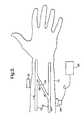
- FIG. 1An artery 10 and a vein 12 are located in the arm 14 of the patient.
- a vessel 16known as an AV graft or shunt, is grafted to connect the artery 10 and the vein 12 .
- AV graft 16is a direct connection between the artery 10 and the vein 12 and has a relatively large cross-sectional area, a high flow through it occurs. The direction of flow is indicated by the arrows in FIG. 1 .
- Catheters(not shown) can be connected to the AV graft 16 , when hemodialysis is required. The catheters can tap into the high flow through the AV graft 16 to provide a high flow to and from the hemodialysis machine.
- stenosis 18occurs at the outflow tract where the AV graft 16 is connected to the vein 12 , that is at the venous anastomosis side of the graft.
- the stenosis 18is an unnatural narrowing of the vessel, and if unopened by angioplasty, the stenosis 18 progresses until the vein 12 is completely blocked.
- the stenosis 18is due to neo-intimal hyperplasia, that is the response of the vessel 16 to the abnormal conditions.
- the flow through the vein 12is typically 10 to 20 times higher than normal. This leads to turbulence and flow separation such that the flow is not smooth or laminar, and the stenosis 18 develops as a result.
- Another factoris that the vein 12 is exposed to a higher blood pressure than normal, because it is directly connected to the artery 10 .
- the blood pressure in an artery 10is typically 100 mm Hg, whereas the blood pressure in a vein 12 is typically 5 mm Hg.
- the vein 12tends to arterialize in response to this, for example by thickening of the vein wall and this may contribute to the stenosis 18 .
- a further possible factoris that, in the presence of the graft, the flow in the vein 12 is pulsatile.
- the pulsatile flowproduces an oscillating stress concentration at the junction, i.e. suture line, between the AV graft 16 and the vein 12 .
- the sutureusually does not fail, the stenosis 18 may be in response to the oscillating stress concentrated at the junction.
- AV graftse.g., AV graft 16
- stenosis 18develops at the venous anastomosis side.
- AV graft survivalis around only 1.5 years.
- surgerysuch as angioplasty to remove the stenosis 18 or surgery to implant a new AV graft in a different limb of the patient.
- a further problemis that the AV graft 16 effectively provides a short circuit between the artery 10 and the vein 12 and the high flow through the AV graft 16 requires a huge additional cardiac output.
- Normal cardiac outputis typically 5 liters per minute, but with the AV graft 16 in place this can increase to 7 liters per minute. This large additional cardiac output can be very problematic indeed, and can result in fatal cardiac failure for about 5% of AV graft patients.
- a method of flow control in an AV graft or an AV fistula used for vascular access for an extracorporeal circuitcomprising the steps of:
- Applying partial constrictioncan reduce or eliminate turbulence, and lower the blood pressure in the vein.
- the constrictioncan also act as a strong wave reflector to reduce or eliminate the pulsatile flow at the venous anastomosis. All of these can alleviate stenosis, prolong the life of the AV graft or the AV fistula and reduce the necessary cardiac output. Changing the degree of constriction when the flow through the extracorporeal circuit is to occur enables a high flow to be provided for vascular access.
- constriction of the vesselis only partial, preferably to maintain a reduced but significant residual flow through the AV graft to avoid thrombosis, and to keep the vein matured and able to handle the high flow when necessary.
- constrictionis applied over an elongate portion of the vessel. This enables the flow control to be achieved by viscous dissipation in favor of turbulent dissipation.
- the constrictionis applied at a plurality of positions along the vessel and/or the profile of the constriction is controlled along its length. This enables turbulence caused by the constriction to be minimized.
- constrictionreduces the cross-sectional area of the lumen of the vessel, but maintains the length of the perimeter thereof, again to favor viscous dissipation.
- the flow at the venous anastomosis of the AV graft or the AV fistulais monitored so that when constricted, the flow is maintained at a level below the onset of turbulence.
- the vesselis an AV graft.
- the constricting stepcomprises constricting the AV graft at its arterial end. This enables any turbulence caused by the constriction to subside before the blood flow reaches the venous anastomosis.
- the inventionprovides a device for controlling flow in an AV graft or an AV fistula used for vascular access for an extracorporeal circuit, the device comprising:
- the inventionalso provides a device, for controlling flow in a bodily vessel, the device comprising an actuator for releasably constricting the bodily vessel, and a rotatable member for driving the actuator.
- the rotatable membercomprises a drive shaft of a motor or comprises a rotor rotatable by an externally applied magnetic field.
- the motoris an electrical micromotor.
- the inventionalso provides a device, for controlling flow in a bodily vessel, the device comprising a deformable member which is reversibly deformable by a change in temperature or magnetic field, and an actuator acted on by the deformable member for releasably constricting the bodily vessel, wherein the deformable member is deformable between a first state in which the actuator applies constriction to the bodily vessel, and a second state in which the actuator reduces the constriction of the bodily vessel.
- the thermally deformable membercomprises a shape-memory material or a liquid filled capsule.
- the device of the inventionfurther comprises an antenna for receiving signals for controlling the actuator. This avoids the need for access to the device through the skin and the potential risk of infection.
- the devicefurther comprises a converter for converting radio frequency energy received by the antenna into energy for powering the device to operate the actuator.
- a converterfor converting radio frequency energy received by the antenna into energy for powering the device to operate the actuator.
- the inventionfurther provides a device, for controlling flow in a bodily vessel, the device comprising an actuator for releasably constricting the bodily vessel, wherein the actuator comprises a clip having two constriction portions with an adjustable separation therebetween for accommodating the bodily vessel and a control portion for releasably holding the two constriction portions such that the separation is held at least one predetermined amount.
- constriction portionsare integrally formed as one member that makes the device simple and cheap to fabricate.
- FIG. 1is a schematic view of a human lower arm, illustrating a conventional AV graft in situ;
- FIG. 2is a close-up view of the venous anastomosis of FIG. 1 , illustrating a problem associated with the AV graft of FIG. 1 ;
- FIG. 3is a schematic view of a human lower arm, illustrating an arrangement according to the present invention
- FIGS. 4( a ) and 4 ( b )are schematic cross-sectional views of a first embodiment of apparatus according to the present invention, shown applied to an AV graft;
- FIG. 4( c )is a plan view of a deflectable membrane of an embodiment of the invention.
- FIG. 5shows a second embodiment of an apparatus according to the present invention
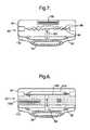
- FIGS. 6( a ) and 6 ( b )show a third embodiment of an apparatus according to the invention in cross-section and plan view, respectively;
- FIGS. 7 and 8show cross-sectional views of fourth and fifth embodiments of apparatus according to the invention.
- FIGS. 9 , 10 and 11are explanatory diagrams for illustrating further aspects of the present invention.
- FIG. 12illustrates schematically an embodiment of the invention incorporating an electromagnetic flow measurement system
- FIG. 13illustrates an application of the invention to a Blalock-Taussig shunt.
- FIG. 3shows an arrangement according to the present invention, with corresponding parts labeled the same as in FIG. 1 .
- the AV graft 16may be an artificial vessel, for example, made of PTFE or GORE-TEX, other synthetic material, or the AV graft 16 may be an autologous graft. As illustrated in FIG. 3 , the AV graft 16 is connected to an artery 10 and a vein 12 in the arm 14 of a patient. However, the AV graft 16 may, of course, be located in other parts of the body, for example the leg, groin or neck.
- a device 20is provided for controlling blood flow in the AV graft 16 .
- the device 20is used to constrict the AV graft 16 such that there is a reduced or residual flow therethrough.
- an extracorporeal circuitsuch as a hemodialysis machine
- the degree of constrictionis reduced, partially or fully, so that there is an increased, high flow through the AV graft 16 .
- Catheterscan tap into the high flow in the AV graft 16 to provide high flow to and from a hemodialysis machine.
- the cathetersmay be upstream or downstream of the device 20 or may be provided on opposite sides of the device 20 .
- a single catheter with a double lumenmay also be used for flow to and from the AV graft 16 .
- the constriction device 20is used to constrict the AV graft 16 at its upstream end, in the vicinity of its connection with the artery 10 .
- the constriction device 20is wholly implanted within the patient and an external controller 22 is used telemetrically to control the constriction device 20 .
- the constriction device 20is used to re-apply constriction to reduce blood flow.
- a turbulence measuring device 24 , 26may be used to monitor turbulence in the vicinity of the venous anastomosis while the flow through the AV graft 16 is being reduced. As the degree of constriction is increased, the flow rate reduces such that a level will be reached at which turbulent flow substantially ceases to be detected by the turbulence measuring device. When this occurs, further change in constriction can be stopped and the flow maintained at that level below the onset of turbulence. Alternatively, the constriction may be increased until the turbulence has been diminished to a predetermined level, but not totally abolished.
- this diminished turbulence intensityis below the level at which stenosis 18 may occur, but the flow rate is still sufficient to keep the vein 12 matured. In this way an optimal quiescent flow can be established in the vicinity of the venous anastomosis side of the AV graft 16 .
- the turbulence measuring device 24 , 26can be a conventional Doppler device or a phonoangiographer and may advantageously be connected to the controller 22 or constriction device 20 automatically to control adjustment of the flow rate, or this may be done manually.
- FIGS. 4( a ) and 4 ( b )are longitudinal and transverse cross-sections, respectively, of a constriction device 20 and a control device 22 .
- the control device 22has an antenna 30 for transmitting signals to an antenna 32 provided on the constriction device 20 .
- the antennae 30 , 32are electromagnetically coupled to each other, but are of course on opposite sides of the skin (not shown) of the patient.
- a receiver 34 connected to antenna 32sends electrical power to a motor 36 in response to the transmitted signal.
- the constriction device 20may contain an internal power source, such as a battery, which is controlled by the receiver 34 to deliver electrical power to the motor 36 .
- the receiver 34may comprise a radio frequency to DC converter and modulator, in which case radio frequency signals emitted by the antenna 30 are picked up by the antenna 32 and these signals are converted by the receiver 34 into electrical power to drive the motor 36 , rather than the signals being used to control an internal power source of the device, thereby eliminating the need for batteries in the device which would need to be replaced periodically.
- the motor 36is a miniature motor, also known as a micro-machine, and when provided with electrical power it can be used to rotate a drive shaft 38 in either direction, or in one direction only, provided that the actuator performs a periodic displacement even if the micromotor shaft 38 always turns in the same direction.
- the dimensions of the micromotor 36are sufficiently small to enable it to be encapsulated in an implantable enclosure, for example the motor may be 2 mm thick and 15 mm long.
- a rotary to linear transmission 40converts the rotation of the drive shaft 38 into linear motion of an actuator comprising members 42 , 44 and 46 .
- Members 42 and 44are rods or bars and member 46 is, for example, a fine titanium membrane that is in contact with the AV graft 16 or presses upon the AV graft 16 through an intermediate material.
- the actuator 42 , 44 , 46is constricting the AV graft 16 , such that the cross-sectional area of its lumen 48 is reduced.
- the constrictioncan be relieved by motion of the actuator, when high flow is required, and the position of the membrane 46 in this high flow state is indicated by the dashed line 50 .
- the constriction device 20is encapsulated in an enclosure 52 , such as a titanium or ceramic box, through which the AV graft 16 can pass, or into which the AV graft 16 can be slotted sideways.
- the antenna 32 as illustrated in FIGS. 4( a ) and 4 ( b )is located outside the enclosure 52 so that it is not screened by the enclosure and to enable the antenna 32 to be placed under the skin for optimal RF wave reception.
- This arrangement of having the antenna 32 external to and optionally remote from the enclosure 52can be advantageous for cases in which the constriction device 20 is implanted deep within the body and the RF waves from the external control unit have a maximum penetration depth of 2 to 4 cm.
- the antenna 32can be internal, i.e. encapsulated within the enclosure 52 of the constriction device 20 .
- the enclosure 52 or at least part of the enclosure 52is non-metallic, for example ceramic or plastic to avoid screening of the RF waves. Having the antenna 32 internal or integral to the enclosure 52 of the constriction device 20 is advantageous in simplifying the implantation of the device within the body.
- the devicemay optionally include a sensor, not shown, such as a sensor for measuring the position of the actuator or for counting the number of revolutions of the drive shaft 38 . Sensors for measuring flow, turbulence or pressure may also be included. Information from the sensor(s) can then be transmitted from the constriction device 20 to the control device 22 via the antennas 30 , 32 , so that the controller 22 can control the constriction more precisely.
- a sensornot shown, such as a sensor for measuring the position of the actuator or for counting the number of revolutions of the drive shaft 38 .
- Sensors for measuring flow, turbulence or pressuremay also be included.
- Information from the sensor(s)can then be transmitted from the constriction device 20 to the control device 22 via the antennas 30 , 32 , so that the controller 22 can control the constriction more precisely.
- FIG. 5illustrates an alternative constriction device 20 in the form of a clip.
- the actuator of the devicecomprises a pair of constriction portions 60 , 62 separated by a gap through which the AV graft 16 passes.
- the separation between the constriction portions 60 , 62can be reduced by applying pressure to the skin 64 of the patient to constrict the AV graft 16 .
- a control portion 66comprises a series of grooves or notches engageable by an insertion portion 68 of the constriction portion 60 . Pressure applied to the skin 64 moves the insertion portion 68 from the position shown in FIG. 5 into successively lower notches. When the required level of constriction is achieved, the engagement of the insertion portion 68 in the particular notch of the control portion 66 maintains that level of constriction.
- a pressing device 70may be used for this process and may comprise a sensor that detects the motion of the insertion portion 68 from one notch to the next so that the position of the constriction portions is known and an optimal level of constriction applied.
- the constrictioncan be reduced by again applying pressure to the skin of the patient, but this time by pressing on a release portion 72 . This splays the control portion 66 so that the insertion 68 disengages from the notches and the opening between the constriction portions 60 , 62 increases.
- the constriction device 20is formed from a single piece, such as by molding it from a biologically compatible plastics material. This makes it very simple and cheap to fabricate.
- FIGS. 6( a ) and 6 ( b )Another embodiment of the constriction device is shown in FIGS. 6( a ) and 6 ( b ). It comprises an actuator plate 80 , within an enclosure 82 , for squeezing on the AV graft 16 .
- a rotor 84is screwed onto a threaded shaft 86 .
- the rotor 84comprises a series of magnetic north and south poles alternating around the shaft 86 .
- the rotor 84can comprise any suitable magnetic material, such as ferrite.
- an alternating or rotating magnetic field from outside the patientcan cause the rotor 84 to revolve about the axis of the shaft 86 .
- the threaded engagement between the rotor 84 and the shaft 86causes the rotor 84 to translate in the axial direction of the shaft 86 , the direction of translation depending on the sense of rotation of the rotor 84 .
- the externally magnetic fieldcan be used to move the rotor 84 along the shaft 86 to urge the actuator plate 80 against the AV graft 16 to apply constriction thereto, or to release pressure from the actuator plate 80 and reduce the constriction when high flow through the AV graft 16 is required.
- FIGS. 7 and 8show two further embodiments of the constriction device 20 of the invention which both operate thermally.
- Each devicehas an actuator comprising a movable member 90 and a flexible membrane 92 for constricting an AV graft 16 , the device being housed in an enclosure 94 .
- the actuator member 90is connected to a sheet 96 made of a heat-deformable material. This is shown in its normal state at body temperature whereby the AV graft 16 is constricted to reduce the quiescent flow therethrough. On raising the temperature of the sheet 96 it deforms into the shape indicated by the dashed line 98 thereby pulling on the actuator 90 , 92 to reduce the constriction on the AV graft 16 .
- the material of the sheet 96may be a shape-memory material, such as a so-called smart metal, or it could be a bi-metallic strip or any other suitable material that deflects on changing temperature, or a shape memory material that is magnetically activated.
- the actuator member 90is connected to a deformable membrane 100 which defines one surface of a liquid filled capsule 102 containing a liquid with a low boiling point, such as just above body temperature, for example around 39 degrees Celsius (C).
- a liquid with a low boiling pointsuch as just above body temperature, for example around 39 degrees Celsius (C).
- the capsule 102contains liquid and the actuator 90 , 92 squeezes the AV graph 16 to reduce blood flow.
- the actuator 90 , 92squeezes the AV graph 16 to reduce blood flow.
- This expansiondeflects the membrane 100 and a force is transmitted via the member 90 to lift the flexible membrane 92 to relieve the constriction of the AV graph 16 .
- the position of the deformable membrane 100 when in this stateis indicated by the dashed line 104 .
- the devices 20 shown in FIGS. 7 and 8may be provided with an optional heater 106 , such as an electrical resistance.
- an optional heater 106such as an electrical resistance.
- electric currentis passed through the heater 106 to raise the temperature of the sheet 96 or liquid filled capsule 102 to move the actuator as described above.
- the electrical currentmay be provided by a battery associated with the device and controlled by signals from an external controller as described with reference to FIGS. 4( a ) and 4 ( b ), or the electrical current may be provided by a radio frequency converter which converts radio frequency radiation into electrical power, without the need for an internal battery, as also described with reference to FIGS. 4( a ) and 4 ( b ).
- the increase in temperature necessary to change the state of the thermal devicemay be provided by an external heat source.
- the external heat sourcemay take the form of, for example, an infrared lamp directed onto the skin in the vicinity of the device 20 .
- the heater 106could also be an antenna which heats up when an appropriate electromagnetic field is applied.
- the enclosures 52 , 82 , 94comprise a titanium, ceramic or plastic box and the dimensions of the sides in transverse cross-section may be in the region of 10 to 30 mm, the unconstricted diameter of an AV graft (e.g., AV graft 16 ) being typically 5 to 8 mm.
- the flexible membrane 46 , 92 , in contact with the AV graft 16may be a very thin (i.e. 20 to 60 micrometers thick) titanium sheet or a thicker titanium membrane preferably with appropriate corrugations 47 to facilitate deflection, as shown in plan view in FIG. 4( c ).
- the corrugations 47can be seen in cross-section in FIGS. 4( a ), 4 ( b ), 7 and 8 .
- the region surrounding the AV graft 16 , but within the respective enclosure, such as the region 110 shown in FIGS. 7 and 8may contain a deformable, but incompressible, material such as gel to control the constriction of the AV graft 16 .
- FIG. 9shows schematically a constriction, such as in an AV graft 16 .
- the normal diameter of the vesselis D
- the constricted diameteris d
- the constrictionis applied over a length L.
- the method and devices of the present inventionapply the constriction over an elongate portion of the AV graft 16 , for example as shown in FIG. 4( a ).
- the length Lis at least twice the original diameter D, and L may even be five to ten or more times the diameter D. The reasons for this are as follows.
- the viscous lossesare proportional to LQ, whereas the turbulent losses are proportional to [(D/d) 2 ⁇ 1] 2 Q 2 .
- These two lossescontribute to the overall dissipation caused by the constriction which results in the pressure drop and reduced flow rate.
- An acute localized constrictionproduces much turbulence which can cause thrombosis or unwanted stenosis (e.g., stenosis 18 ) downstream at the venous anastomosis, or in the AV graft 16 itself if it is made of living tissue.
- the same overall flow reductioncan be achieved by increasing the length of the constriction to increase viscous loss, but reducing turbulent loss.
- One way to increase the length of the constrictionis to provide multiple constriction devices in series along the AV graft 16 .
- Another methodis to provide a single elongate actuator within the device or multiple actuators disposed along the length of the device.
- FIG. 10illustrates a further technique for reducing turbulence caused by the constriction, namely by controlling the profile of the constriction such that abrupt transitions in diameter are avoided.
- the profile of the constrictioncan be controlled by providing a plurality of actuators 120 , each of which squeezes the AV graft 16 by a controlled amount.
- the actuators 120may all be provided within a single constriction device, or each actuator 120 may be provided in a respective constriction device disposed in series along the AV graft 16 .
- a single actuator of a predetermined profilemay be used to cause a desired constriction profile.
- FIG. 11A further technique for favoring viscous dissipation over turbulent dissipation is illustrated with reference to FIG. 11 .
- a transverse cross-section of the unconstricted AV graft 16is approximately circular as shown in the center of FIG. 11 .
- Applying an isotopic force around the periphery to squeeze the vessel approximately equally in all directionswould tend to reduce the cross-section of the vessel to be a circle of smaller diameter.
- viscous lossesare related to the area of the wall of the vessel and hence to the perimeter of the cross-section.
- the perimeter of the lumencan be maintained substantially constant in length while reducing its cross-sectional area.
- Various exemplary resulting shapesare shown in FIG. 11 .
- the arrowsillustrate the directions and points of application of the squeezing force.
- the devices according to the inventioncan achieve constrictions of these shapes by a variety of ways, such as having ridged actuators, or a plurality of actuators applying pressure in different directions or surrounding the AV graft 16 by a gel to control the shape of the deformation.
- a further feature of the inventionis to adhere the outer surface of the AV graft 16 to the actuator (e.g., actuator 42 , 44 or 46 ) using a glue.
- the actuatore.g., actuator 42 , 44 or 46
- p+ 1 /2 ⁇ 2is constant, where p is pressure, ⁇ is viscosity and ⁇ is flow velocity.
- the flow velocityincreases to maintain throughput.
- the pressure given by Bernoulli's equationcan become lower than the external pressure on the vessel or even become negative.
- Gluing the wall of the AV graft (e.g., AV graft 16 ) to the actuator (e.g., actuator 42 , 44 , or 46 )prevents collapse by maintaining a minimum diameter of the AV graft (e.g., AV graft 16 ), even when constricted. Collapse of the AV graft (e.g., AV graft 16 ) may also be prevented if the constriction is appropriately shaped, as shown in some of the examples in FIG. 11 , to resist further buckling under reduced pressure.
- catheters for extracorporeal flow to and from the AV graft 16may be provided on opposite sides of the device 20 .
- the constrictionis still partially applied to alleviate the problems, such as caused by turbulence, whilst keeping the vein (e.g., vein 12 ) matured.
- the method and device of the inventioncan also be used with AV fistulas, in which case the flow control device is placed on the artery or the vein, just proximal or distal to the fistula, respectively.
- a further preferred aspect of the inventionwhich can be used with any of the above-described embodiments, is to incorporate a flow-measuring device into the variable flow control device 20 .
- FIG. 3illustrated an external flow or turbulence measuring device 24 , 26 , however, according to the present further embodiment, the implanted device incorporates flow-measuring apparatus.
- the flow measured by the devicemay be communicated, for example, via an antenna 32 , to an external device to give a reading of the flow passing through the AV graft (e.g., AV graft 16 ).
- the flow measurementmay be used internally within the implanted device to control the constriction applied, using a feed-back loop, to regulate the flow.
- a piezo-elementemits ultrasound, which is reflected by the flowing blood, the reflected signals being slightly changed in frequency through the Doppler effect, thereby carrying information on velocity which is detected.
- the information on velocityis transmitted from the implanted device 20 via the antenna 32 to the external antenna 30 and is then received and displayed by the external control unit 22 .
- the flow meterworks on the principle of Faraday's Law of Induction, which states that if a conductor is moved within a magnetic field, a voltage is induced at right angles to the direction of movement in that conductor and at right angles to the magnetic field.
- the voltage generatedis proportional to the average velocity of the moving conductor.
- FIG. 12An example of this embodiment is illustrated in FIG. 12 .
- the blood in the vessel 16acts as the moving conductor.
- a magnetic field Bcan be applied by an external magnet.
- the magnetic field coming from the external antenna 30is used. This is advantageous because it eliminates the need to install magnets or other means of imposing a magnetic field.
- the magnetic fieldis alternating, in which case a different frequency of B is used other than the one used for the control of the flow control device 20 .
- the external control unit 22emits one frequency, for example, for the telemetric control of a motor 36 and for power generation, and another frequency for creating the magnetic field B required for the flow measurement.
- the voltage measuring electrodes measuring 120are placed perpendicular to B and v, and with a precisely known separation D.
- the EMF generated between the electrodes 120is sensed by a voltage measuring device 122 .
- the voltage measuring device 122is tuned to the frequency of the externally applied magnetic field B.
- the electrodes 120can be encapsulated either in the main box of the device 20 or in an auxiliary chamber next to the main box.
- AV graftAll of the preceding methods and devices according to the invention have been described in terms of application to an AV graft. However, as mentioned in the introduction, they can also be applied to the variable flow control of other bodily vessels, by which is meant a generally tubular structure that transports material in the body, such as a blood vessel, lymph vessel, vessel in the digestive tract, vessel in the urinary tract, vessel in the reproductive tract, and so on.
- the bodily vesselcan be natural, or a graft, such as an autologous graft or a synthetic graft. Two further exemplary embodiments of applications other than to AV grafts will now be described.
- pulmonary circulationmust often be assured by providing a shunt 200 connecting the subclavian or innominate artery 202 to the right or left pulmonary artery 204 .
- Thisis also known as the modified Blalock-Taussig shunt.
- the shunt 200itself is a vascular graft, such as a PTFE tube. Survival of the patent is often dependent on the optimal distribution of flow between the shunt 200 and the aorta 206 .
- a variable flow control device 20is placed on the shunt 200 .
- the shunt 200drives flow from the systemic circulation in the innominate artery 202 to the pulmonary circulation in the pulmonary artery 204 .
- the variable flow control device 20is, for example, according to any one of the above described devices.
- the flow control device 20enables the flow in the shunt 200 to be regulated and according to a method of the invention, the flow in the shunt 200 is controlled to equilibrate the repartition of flow between the systemic and pulmonary circulation.
- the valve at the end of the esophagus connecting the esophageal tube to the stomachmay fail, causing re-entry of food from the stomach to the esophagus and consequent discomfort to the patient.
- a banding at the end of the esophagusmay be surgically placed. The banding causes a localized restriction to the esophageal tube. Banding is not a precise procedure and is not adjustable without further abdominal surgery.
- a variable flow control devicesuch as embodied above, is located on the esophagus to alleviate either of these problems.
- the degree of esophageal restrictioncan be easily controlled telemetrically to allow controlled passage of food into the stomach when required but to restrict it at other times or to prevent re-entry of food from the stomach into the esophagus.
Landscapes
- Health & Medical Sciences (AREA)
- Heart & Thoracic Surgery (AREA)
- Life Sciences & Earth Sciences (AREA)
- Vascular Medicine (AREA)
- Veterinary Medicine (AREA)
- Animal Behavior & Ethology (AREA)
- Engineering & Computer Science (AREA)
- Biomedical Technology (AREA)
- Public Health (AREA)
- General Health & Medical Sciences (AREA)
- Cardiology (AREA)
- Surgery (AREA)
- Transplantation (AREA)
- Hematology (AREA)
- Reproductive Health (AREA)
- Gastroenterology & Hepatology (AREA)
- Pulmonology (AREA)
- Medical Informatics (AREA)
- Oral & Maxillofacial Surgery (AREA)
- Molecular Biology (AREA)
- Nuclear Medicine, Radiotherapy & Molecular Imaging (AREA)
- Anesthesiology (AREA)
- Prostheses (AREA)
- External Artificial Organs (AREA)
- Paper (AREA)
- Flow Control (AREA)
- Vehicle Body Suspensions (AREA)
- Measuring Volume Flow (AREA)
- Massaging Devices (AREA)
- Electrical Discharge Machining, Electrochemical Machining, And Combined Machining (AREA)
Abstract
Description
Claims (3)
Priority Applications (1)
| Application Number | Priority Date | Filing Date | Title |
|---|---|---|---|
| US13/036,358US8506517B2 (en) | 1999-07-19 | 2011-02-28 | Flow control method and device |
Applications Claiming Priority (7)
| Application Number | Priority Date | Filing Date | Title |
|---|---|---|---|
| EP99305689.4 | 1999-07-19 | ||
| EP99305689 | 1999-07-19 | ||
| EP99305689AEP1072282A1 (en) | 1999-07-19 | 1999-07-19 | Flow control device |
| PCT/EP2000/006907WO2001005463A1 (en) | 1999-07-19 | 2000-07-19 | Flow control method and device |
| US10/031,469US7128750B1 (en) | 1999-07-19 | 2000-07-19 | Flow control method and device |
| US11/586,886US8079974B2 (en) | 1999-07-19 | 2006-10-26 | Flow control method and device |
| US13/036,358US8506517B2 (en) | 1999-07-19 | 2011-02-28 | Flow control method and device |
Related Parent Applications (1)
| Application Number | Title | Priority Date | Filing Date |
|---|---|---|---|
| US11/586,886ContinuationUS8079974B2 (en) | 1999-07-19 | 2006-10-26 | Flow control method and device |
Publications (2)
| Publication Number | Publication Date |
|---|---|
| US20110144670A1 US20110144670A1 (en) | 2011-06-16 |
| US8506517B2true US8506517B2 (en) | 2013-08-13 |
Family
ID=8241527
Family Applications (6)
| Application Number | Title | Priority Date | Filing Date |
|---|---|---|---|
| US10/031,469Expired - LifetimeUS7128750B1 (en) | 1999-07-19 | 2000-07-19 | Flow control method and device |
| US11/586,886Expired - Fee RelatedUS8079974B2 (en) | 1999-07-19 | 2006-10-26 | Flow control method and device |
| US13/018,322AbandonedUS20110130702A1 (en) | 1999-07-19 | 2011-01-31 | Flow control method and device |
| US13/018,270Expired - Fee RelatedUS8932247B2 (en) | 1999-07-19 | 2011-01-31 | Flow control method and device |
| US13/036,358Expired - Fee RelatedUS8506517B2 (en) | 1999-07-19 | 2011-02-28 | Flow control method and device |
| US13/184,340Expired - Fee RelatedUS8821430B2 (en) | 1999-07-19 | 2011-07-15 | Flow control method and device |
Family Applications Before (4)
| Application Number | Title | Priority Date | Filing Date |
|---|---|---|---|
| US10/031,469Expired - LifetimeUS7128750B1 (en) | 1999-07-19 | 2000-07-19 | Flow control method and device |
| US11/586,886Expired - Fee RelatedUS8079974B2 (en) | 1999-07-19 | 2006-10-26 | Flow control method and device |
| US13/018,322AbandonedUS20110130702A1 (en) | 1999-07-19 | 2011-01-31 | Flow control method and device |
| US13/018,270Expired - Fee RelatedUS8932247B2 (en) | 1999-07-19 | 2011-01-31 | Flow control method and device |
Family Applications After (1)
| Application Number | Title | Priority Date | Filing Date |
|---|---|---|---|
| US13/184,340Expired - Fee RelatedUS8821430B2 (en) | 1999-07-19 | 2011-07-15 | Flow control method and device |
Country Status (12)
| Country | Link |
|---|---|
| US (6) | US7128750B1 (en) |
| EP (2) | EP1072282A1 (en) |
| JP (1) | JP2003504166A (en) |
| CN (1) | CN1374877A (en) |
| AT (1) | ATE276790T1 (en) |
| AU (1) | AU6275700A (en) |
| CA (1) | CA2379788A1 (en) |
| DE (1) | DE60014101T3 (en) |
| ES (1) | ES2226885T5 (en) |
| IL (1) | IL147693A0 (en) |
| MX (1) | MXPA02000624A (en) |
| WO (1) | WO2001005463A1 (en) |
Cited By (26)
| Publication number | Priority date | Publication date | Assignee | Title |
|---|---|---|---|---|
| US9339636B1 (en) | 2012-09-06 | 2016-05-17 | Mubashir H Khan | Subcutaneous fluid pump |
| US9526648B2 (en) | 2010-06-13 | 2016-12-27 | Synerz Medical, Inc. | Intragastric device for treating obesity |
| WO2017040366A1 (en)* | 2015-08-28 | 2017-03-09 | University Of Cincinnati | Arteriovenous fistula implant effective for inducing laminar blood flow |
| US9980813B2 (en) | 2014-04-28 | 2018-05-29 | Cook Medical Technologies Llc | Selective fluid barrier valve device and method of treatment |
| US10039552B2 (en) | 2014-10-28 | 2018-08-07 | Cook Medical Technologies Llc | Magnetically actuated gating devices, systems, kits, and methods |
| US10349982B2 (en) | 2011-11-01 | 2019-07-16 | Nuvasive Specialized Orthopedics, Inc. | Adjustable magnetic devices and methods of using same |
| US10413436B2 (en) | 2010-06-13 | 2019-09-17 | W. L. Gore & Associates, Inc. | Intragastric device for treating obesity |
| US10420665B2 (en) | 2010-06-13 | 2019-09-24 | W. L. Gore & Associates, Inc. | Intragastric device for treating obesity |
| US10478232B2 (en) | 2009-04-29 | 2019-11-19 | Nuvasive Specialized Orthopedics, Inc. | Interspinous process device and method |
| US10617453B2 (en) | 2015-10-16 | 2020-04-14 | Nuvasive Specialized Orthopedics, Inc. | Adjustable devices for treating arthritis of the knee |
| US10646262B2 (en) | 2011-02-14 | 2020-05-12 | Nuvasive Specialized Orthopedics, Inc. | System and method for altering rotational alignment of bone sections |
| US10660675B2 (en) | 2010-06-30 | 2020-05-26 | Nuvasive Specialized Orthopedics, Inc. | External adjustment device for distraction device |
| US10729470B2 (en) | 2008-11-10 | 2020-08-04 | Nuvasive Specialized Orthopedics, Inc. | External adjustment device for distraction device |
| US10743794B2 (en) | 2011-10-04 | 2020-08-18 | Nuvasive Specialized Orthopedics, Inc. | Devices and methods for non-invasive implant length sensing |
| US10751094B2 (en) | 2013-10-10 | 2020-08-25 | Nuvasive Specialized Orthopedics, Inc. | Adjustable spinal implant |
| US10779980B2 (en) | 2016-04-27 | 2020-09-22 | Synerz Medical, Inc. | Intragastric device for treating obesity |
| US10835290B2 (en) | 2015-12-10 | 2020-11-17 | Nuvasive Specialized Orthopedics, Inc. | External adjustment device for distraction device |
| US10918425B2 (en) | 2016-01-28 | 2021-02-16 | Nuvasive Specialized Orthopedics, Inc. | System and methods for bone transport |
| US11135078B2 (en) | 2010-06-13 | 2021-10-05 | Synerz Medical, Inc. | Intragastric device for treating obesity |
| US11191579B2 (en) | 2012-10-29 | 2021-12-07 | Nuvasive Specialized Orthopedics, Inc. | Adjustable devices for treating arthritis of the knee |
| US11202707B2 (en) | 2008-03-25 | 2021-12-21 | Nuvasive Specialized Orthopedics, Inc. | Adjustable implant system |
| US11234849B2 (en) | 2006-10-20 | 2022-02-01 | Nuvasive Specialized Orthopedics, Inc. | Adjustable implant and method of use |
| US11246694B2 (en) | 2014-04-28 | 2022-02-15 | Nuvasive Specialized Orthopedics, Inc. | System for informational magnetic feedback in adjustable implants |
| US11357549B2 (en) | 2004-07-02 | 2022-06-14 | Nuvasive Specialized Orthopedics, Inc. | Expandable rod system to treat scoliosis and method of using the same |
| US11439449B2 (en) | 2014-12-26 | 2022-09-13 | Nuvasive Specialized Orthopedics, Inc. | Systems and methods for distraction |
| US11612416B2 (en) | 2015-02-19 | 2023-03-28 | Nuvasive Specialized Orthopedics, Inc. | Systems and methods for vertebral adjustment |
Families Citing this family (159)
| Publication number | Priority date | Publication date | Assignee | Title |
|---|---|---|---|---|
| US6254601B1 (en) | 1998-12-08 | 2001-07-03 | Hysterx, Inc. | Methods for occlusion of the uterine arteries |
| EP1072282A1 (en)* | 1999-07-19 | 2001-01-31 | EndoArt S.A. | Flow control device |
| US6550482B1 (en) | 2000-04-21 | 2003-04-22 | Vascular Control Systems, Inc. | Methods for non-permanent occlusion of a uterine artery |
| US7223279B2 (en) | 2000-04-21 | 2007-05-29 | Vascular Control Systems, Inc. | Methods for minimally-invasive, non-permanent occlusion of a uterine artery |
| US6638286B1 (en) | 2000-11-16 | 2003-10-28 | Vascular Control Systems, Inc. | Doppler directed suture ligation device and method |
| US6635065B2 (en) | 2000-11-16 | 2003-10-21 | Vascular Control Systems, Inc. | Doppler directed suture ligation device and method |
| US7354444B2 (en) | 2001-03-28 | 2008-04-08 | Vascular Control Systems, Inc. | Occlusion device with deployable paddles for detection and occlusion of blood vessels |
| JP4227415B2 (en)* | 2001-03-28 | 2009-02-18 | ヴァスキュラー・コントロール・システムズ・インコーポレーテッド | Method and apparatus for detecting and ligating uterine arteries |
| US6663596B2 (en) | 2001-08-13 | 2003-12-16 | Scimed Life Systems, Inc. | Delivering material to a patient |
| EP1469782A1 (en)* | 2002-01-22 | 2004-10-27 | Arts Medical S.A. | Coronary inflow occlusion and anastomotic assist device |
| EP1343112A1 (en)* | 2002-03-08 | 2003-09-10 | EndoArt S.A. | Implantable device |
| US7207996B2 (en) | 2002-04-04 | 2007-04-24 | Vascular Control Systems, Inc. | Doppler directed suturing and compression device and method |
| US7338433B2 (en) | 2002-08-13 | 2008-03-04 | Allergan, Inc. | Remotely adjustable gastric banding method |
| DK1553878T3 (en) | 2002-08-28 | 2010-05-31 | Allergan Inc | Fatigue resistant gastric banding device |
| US20040097961A1 (en) | 2002-11-19 | 2004-05-20 | Vascular Control System | Tenaculum for use with occlusion devices |
| US7172603B2 (en) | 2002-11-19 | 2007-02-06 | Vascular Control Systems, Inc. | Deployable constrictor for uterine artery occlusion |
| US7404821B2 (en) | 2003-01-30 | 2008-07-29 | Vascular Control Systems, Inc. | Treatment for post partum hemorrhage |
| US7651511B2 (en) | 2003-02-05 | 2010-01-26 | Vascular Control Systems, Inc. | Vascular clamp for caesarian section |
| US7333844B2 (en) | 2003-03-28 | 2008-02-19 | Vascular Control Systems, Inc. | Uterine tissue monitoring device and method |
| WO2004091696A1 (en)* | 2003-04-08 | 2004-10-28 | The Board Of Trustees Of The Leland Stanford Junior University | Implantable arteriovenous shunt device |
| ATE511875T1 (en)* | 2003-04-23 | 2011-06-15 | Interrad Medical Inc | DIALYSE VALVE |
| US8114044B2 (en)* | 2003-06-06 | 2012-02-14 | Creativasc Medical, Llc | Arteriovenous access valve system and process |
| US7762977B2 (en) | 2003-10-08 | 2010-07-27 | Hemosphere, Inc. | Device and method for vascular access |
| US20050137614A1 (en)* | 2003-10-08 | 2005-06-23 | Porter Christopher H. | System and method for connecting implanted conduits |
| US7325546B2 (en) | 2003-11-20 | 2008-02-05 | Vascular Control Systems, Inc. | Uterine artery occlusion device with cervical receptacle |
| US7686817B2 (en) | 2003-11-25 | 2010-03-30 | Vascular Control Systems, Inc. | Occlusion device for asymmetrical uterine artery anatomy |
| JP2007527279A (en) | 2004-01-23 | 2007-09-27 | アラーガン、インコーポレイテッド | One-piece adjustable gastric band that can be fixed removably |
| CA2559056A1 (en) | 2004-03-08 | 2005-09-22 | Endoart S.A. | Closure system for tubular organs |
| EP1732635B1 (en) | 2004-03-18 | 2011-07-27 | Allergan, Inc. | Apparatus for volume adjustment of intragastric balloons |
| US20060047337A1 (en) | 2004-08-27 | 2006-03-02 | Brenneman Rodney A | Device and method for establishing an artificial arterio-venous fistula |
| US7828814B2 (en) | 2004-08-27 | 2010-11-09 | Rox Medical, Inc. | Device and method for establishing an artificial arterio-venous fistula |
| US9706997B2 (en) | 2004-08-27 | 2017-07-18 | Rox Medical, Inc. | Device and method for establishing an artificial arterio-venous fistula |
| US7875036B2 (en) | 2004-10-27 | 2011-01-25 | Vascular Control Systems, Inc. | Short term treatment for uterine disorder |
| US20060122565A1 (en)* | 2004-11-23 | 2006-06-08 | Kooi Chee C | Switch structures or the like based on a thermoresponsive polymer |
| US8226592B2 (en)* | 2004-12-15 | 2012-07-24 | Rox Medical, Inc. | Method of treating COPD with artificial arterio-venous fistula and flow mediating systems |
| JP4798522B2 (en)* | 2005-03-08 | 2011-10-19 | 修 松村 | Penis erection control method and penis erection control device |
| US8251888B2 (en) | 2005-04-13 | 2012-08-28 | Mitchell Steven Roslin | Artificial gastric valve |
| WO2010035271A1 (en) | 2008-09-26 | 2010-04-01 | Vascular Dynamics Inc. | Devices and methods for control of blood pressure |
| US9642726B2 (en) | 2005-07-25 | 2017-05-09 | Vascular Dynamics, Inc. | Devices and methods for control of blood pressure |
| US9125732B2 (en) | 2005-07-25 | 2015-09-08 | Vascular Dynamics, Inc. | Devices and methods for control of blood pressure |
| US20110077729A1 (en)* | 2009-09-29 | 2011-03-31 | Vascular Dynamics Inc. | Devices and methods for control of blood pressure |
| US20110118773A1 (en)* | 2005-07-25 | 2011-05-19 | Rainbow Medical Ltd. | Elliptical device for treating afterload |
| US9592136B2 (en) | 2005-07-25 | 2017-03-14 | Vascular Dynamics, Inc. | Devices and methods for control of blood pressure |
| US8923972B2 (en) | 2005-07-25 | 2014-12-30 | Vascular Dynamics, Inc. | Elliptical element for blood pressure reduction |
| US7798954B2 (en) | 2006-01-04 | 2010-09-21 | Allergan, Inc. | Hydraulic gastric band with collapsible reservoir |
| US8043206B2 (en) | 2006-01-04 | 2011-10-25 | Allergan, Inc. | Self-regulating gastric band with pressure data processing |
| EP2037999B1 (en) | 2006-07-07 | 2016-12-28 | Proteus Digital Health, Inc. | Smart parenteral administration system |
| US20080077070A1 (en)* | 2006-08-10 | 2008-03-27 | Kopia Gregory A | Arteriovenous shunt |
| US8246533B2 (en) | 2006-10-20 | 2012-08-21 | Ellipse Technologies, Inc. | Implant system with resonant-driven actuator |
| US20080097249A1 (en)* | 2006-10-20 | 2008-04-24 | Ellipse Technologies, Inc. | External sensing system for gastric restriction devices |
| US9039758B2 (en)* | 2006-12-07 | 2015-05-26 | Stanley Batiste | Bypass vascular graft |
| US9549808B2 (en) | 2006-12-07 | 2017-01-24 | Stanley Batiste | Bypass configuration and method of construction |
| US9603695B2 (en) | 2006-12-07 | 2017-03-28 | Stanley Batiste | Bypass vascular graft |
| EP1998054B1 (en)* | 2007-05-24 | 2014-08-13 | Parker Origa Holding AG | Pneumatic cylinder with self-adjusting cushioning at the end of stroke and corresponding method |
| US9125979B2 (en) | 2007-10-25 | 2015-09-08 | Proteus Digital Health, Inc. | Fluid transfer port information system |
| US20090112262A1 (en) | 2007-10-30 | 2009-04-30 | Scott Pool | Skeletal manipulation system |
| US8419638B2 (en) | 2007-11-19 | 2013-04-16 | Proteus Digital Health, Inc. | Body-associated fluid transport structure evaluation devices |
| EP2237742A4 (en)* | 2007-12-31 | 2015-02-25 | Bard Inc C R | Vascular graft prosthesis with selective flow reduction |
| US20110295181A1 (en) | 2008-03-05 | 2011-12-01 | Hemosphere, Inc. | Implantable and removable customizable body conduit |
| WO2009120764A2 (en) | 2008-03-25 | 2009-10-01 | Ellipse Technologies, Inc. | Systems and methods for adjusting an annuloplasty ring with an integrated magnetic drive |
| AU2009257591A1 (en) | 2008-06-11 | 2009-12-17 | Allergan, Inc. | Implantable pump system |
| US20100056978A1 (en)* | 2008-08-27 | 2010-03-04 | Lindsay Machan | Externally adjustable blood flow valve |
| WO2010042493A1 (en) | 2008-10-06 | 2010-04-15 | Allergan, Inc. | Mechanical gastric band with cushions |
| US20100185049A1 (en) | 2008-10-22 | 2010-07-22 | Allergan, Inc. | Dome and screw valves for remotely adjustable gastric banding systems |
| US8197490B2 (en) | 2009-02-23 | 2012-06-12 | Ellipse Technologies, Inc. | Non-invasive adjustable distraction system |
| EP2531096A4 (en) | 2010-02-01 | 2013-09-11 | Proteus Digital Health Inc | Two-wrist data gathering system |
| BR112012019212A2 (en) | 2010-02-01 | 2017-06-13 | Proteus Digital Health Inc | data collection system |
| US8678993B2 (en) | 2010-02-12 | 2014-03-25 | Apollo Endosurgery, Inc. | Remotely adjustable gastric banding system |
| US8758221B2 (en) | 2010-02-24 | 2014-06-24 | Apollo Endosurgery, Inc. | Source reservoir with potential energy for remotely adjustable gastric banding system |
| US8764624B2 (en) | 2010-02-25 | 2014-07-01 | Apollo Endosurgery, Inc. | Inductively powered remotely adjustable gastric banding system |
| US8840541B2 (en) | 2010-02-25 | 2014-09-23 | Apollo Endosurgery, Inc. | Pressure sensing gastric banding system |
| US8939888B2 (en) | 2010-04-28 | 2015-01-27 | Apollo Endosurgery, Inc. | Method and system for determining the pressure of a fluid in a syringe, an access port, a catheter, and a gastric band |
| US9044298B2 (en) | 2010-04-29 | 2015-06-02 | Apollo Endosurgery, Inc. | Self-adjusting gastric band |
| US20110270024A1 (en) | 2010-04-29 | 2011-11-03 | Allergan, Inc. | Self-adjusting gastric band having various compliant components |
| US9028394B2 (en) | 2010-04-29 | 2015-05-12 | Apollo Endosurgery, Inc. | Self-adjusting mechanical gastric band |
| US20110270025A1 (en) | 2010-04-30 | 2011-11-03 | Allergan, Inc. | Remotely powered remotely adjustable gastric band system |
| US9226840B2 (en) | 2010-06-03 | 2016-01-05 | Apollo Endosurgery, Inc. | Magnetically coupled implantable pump system and method |
| US8517915B2 (en) | 2010-06-10 | 2013-08-27 | Allergan, Inc. | Remotely adjustable gastric banding system |
| WO2012021378A2 (en) | 2010-08-09 | 2012-02-16 | Ellipse Technologies, Inc. | Maintenance feature in magnetic implant |
| US8698373B2 (en) | 2010-08-18 | 2014-04-15 | Apollo Endosurgery, Inc. | Pare piezo power with energy recovery |
| US9211207B2 (en) | 2010-08-18 | 2015-12-15 | Apollo Endosurgery, Inc. | Power regulated implant |
| US20120059216A1 (en) | 2010-09-07 | 2012-03-08 | Allergan, Inc. | Remotely adjustable gastric banding system |
| CN101919723A (en)* | 2010-09-08 | 2010-12-22 | 中南大学 | Real-time control device for animal blood flow in surgical operation |
| US8961393B2 (en) | 2010-11-15 | 2015-02-24 | Apollo Endosurgery, Inc. | Gastric band devices and drive systems |
| NL2007134C2 (en)* | 2011-02-03 | 2012-08-09 | Geva Sol B V | Controllable flow regulator system. |
| WO2012104848A1 (en)* | 2011-02-03 | 2012-08-09 | Geva Sol Bv | Controllable flow regulator system |
| US8541069B2 (en)* | 2011-04-11 | 2013-09-24 | United Technologies Corporation | Method of guided non-line of sight coating |
| US8725435B2 (en) | 2011-04-13 | 2014-05-13 | Apollo Endosurgery, Inc. | Syringe-based leak detection system |
| CN102302387B (en)* | 2011-06-17 | 2014-05-28 | 中国人民解放军第二军医大学 | Small and medium diameter artificial blood vessel with adjustable pressure and flow |
| ES2744949T3 (en) | 2011-08-01 | 2020-02-26 | Laminate Medical Tech Ltd | Vessel forming devices |
| CN103889481B (en) | 2011-08-02 | 2016-03-09 | 美敦力公司 | Hemodialysis system with flow path with controlled compliance volume |
| WO2013018133A1 (en)* | 2011-08-02 | 2013-02-07 | J.Morita Manufacturing Corporation | Pulmonary artery band |
| JP6199866B2 (en) | 2011-09-06 | 2017-09-20 | メリット・メディカル・システムズ・インコーポレイテッドMerit Medical Systems,Inc. | Vascular access system having a connecting portion |
| US8876694B2 (en) | 2011-12-07 | 2014-11-04 | Apollo Endosurgery, Inc. | Tube connector with a guiding tip |
| US9163623B2 (en)* | 2011-12-08 | 2015-10-20 | Carefusion 303, Inc. | System and method for improved flow uniformity in a peristaltic pump mechanism |
| US8961394B2 (en) | 2011-12-20 | 2015-02-24 | Apollo Endosurgery, Inc. | Self-sealing fluid joint for use with a gastric band |
| WO2013096548A1 (en)* | 2011-12-23 | 2013-06-27 | Volcano Corporation | Methods and apparatus for regulating blood pressure |
| US8968233B2 (en) | 2012-02-03 | 2015-03-03 | Medtronic Vascular, Inc. | Arteriovenous shunt having a moveable valve |
| CN104837514B (en) | 2012-08-01 | 2017-05-17 | 拉米内特医疗技术有限公司 | Devices for forming arteriovenous fistulas |
| US9713666B2 (en) | 2013-01-09 | 2017-07-25 | Medtronic, Inc. | Recirculating dialysate fluid circuit for blood measurement |
| US11154648B2 (en) | 2013-01-09 | 2021-10-26 | Medtronic, Inc. | Fluid circuits for sorbent cartridge with sensors |
| US10850016B2 (en) | 2013-02-01 | 2020-12-01 | Medtronic, Inc. | Modular fluid therapy system having jumpered flow paths and systems and methods for cleaning and disinfection |
| US10010663B2 (en) | 2013-02-01 | 2018-07-03 | Medtronic, Inc. | Fluid circuit for delivery of renal replacement therapies |
| US9623164B2 (en) | 2013-02-01 | 2017-04-18 | Medtronic, Inc. | Systems and methods for multifunctional volumetric fluid control |
| US10537875B2 (en) | 2013-11-26 | 2020-01-21 | Medtronic, Inc. | Precision recharging of sorbent materials using patient and session data |
| US9884145B2 (en) | 2013-11-26 | 2018-02-06 | Medtronic, Inc. | Parallel modules for in-line recharging of sorbents using alternate duty cycles |
| US10682453B2 (en) | 2013-12-20 | 2020-06-16 | Merit Medical Systems, Inc. | Vascular access system with reinforcement member |
| WO2015134747A1 (en)* | 2014-03-06 | 2015-09-11 | Mayo Foundation For Medical Education And Research | Apparatus and methods of inducing weight loss using blood flow control |
| AU2015249561B2 (en) | 2014-04-25 | 2019-08-15 | CreatiVasc Medical Corporation | Magnetically activated arteriovenous access valve system and related methods |
| US9561320B2 (en) | 2014-06-05 | 2017-02-07 | Cook Medical Technologies Llc | Device for promoting fistula patency and method |
| EP2952142B1 (en) | 2014-06-06 | 2017-09-06 | Cook Medical Technologies LLC | Device for forming fistula between blood vessels |
| JP6326995B2 (en)* | 2014-06-12 | 2018-05-23 | ニプロ株式会社 | Blood flow regulator |
| WO2015199768A1 (en) | 2014-06-24 | 2015-12-30 | Medtronic, Inc. | Stacked sorbent assembly |
| ES2989503T3 (en) | 2014-06-24 | 2024-11-26 | Mozarc Medical Us Llc | Modular dialysate regeneration assembly |
| US10667931B2 (en) | 2014-07-20 | 2020-06-02 | Restore Medical Ltd. | Pulmonary artery implant apparatus and methods of use thereof |
| KR102346227B1 (en)* | 2014-11-19 | 2021-12-31 | 삼성전자주식회사 | Apparatus and system for generating extreme ultraviolet light and using method for use of the same |
| JP6495062B2 (en)* | 2015-03-20 | 2019-04-03 | 国立大学法人東北大学 | Medical active clip |
| US9655777B2 (en)* | 2015-04-07 | 2017-05-23 | Novartis Ag | System and method for diagphragm pumping using heating element |
| US10022252B2 (en) | 2015-06-10 | 2018-07-17 | Cook Medical Technologies Llc | Spiral blood flow device with diameter independent helix angle |
| US11771434B2 (en) | 2016-09-28 | 2023-10-03 | Restore Medical Ltd. | Artery medical apparatus and methods of use thereof |
| WO2018089625A2 (en) | 2016-11-10 | 2018-05-17 | Merit Medical Systems, Inc. | Anchor device for vascular anastomosis |
| US10981148B2 (en) | 2016-11-29 | 2021-04-20 | Medtronic, Inc. | Zirconium oxide module conditioning |
| US11383072B2 (en) | 2017-01-12 | 2022-07-12 | Merit Medical Systems, Inc. | Methods and systems for selection and use of connectors between conduits |
| US10610633B2 (en)* | 2017-01-23 | 2020-04-07 | Mohammed Ibn khayat Zougari | Contactless actuation for valve implant |
| EP4461262A3 (en) | 2017-01-25 | 2025-02-26 | Merit Medical Systems, Inc. | Systems for facilitating laminar flow between conduits |
| US11026704B2 (en) | 2017-03-06 | 2021-06-08 | Merit Medical Systems, Inc. | Vascular access assembly declotting systems and methods |
| US10925710B2 (en) | 2017-03-24 | 2021-02-23 | Merit Medical Systems, Inc. | Subcutaneous vascular assemblies for improving blood flow and related devices and methods |
| WO2018225059A1 (en) | 2017-06-05 | 2018-12-13 | Restore Medical Ltd | Double walled fixed length stent like apparatus and methods of use thereof |
| US10960381B2 (en) | 2017-06-15 | 2021-03-30 | Medtronic, Inc. | Zirconium phosphate disinfection recharging and conditioning |
| WO2019014444A2 (en) | 2017-07-14 | 2019-01-17 | Merit Medical Systems, Inc. | Releasable conduit connectors |
| US11911585B2 (en) | 2017-07-20 | 2024-02-27 | Merit Medical Systems, Inc. | Methods and systems for coupling conduits |
| US11166849B2 (en) | 2017-07-20 | 2021-11-09 | Shifamed Holdings, Llc | Adjustable flow glaucoma shunts and methods for making and using same |
| EP4218692A3 (en) | 2017-07-20 | 2023-09-06 | Shifamed Holdings, LLC | Adjustable flow glaucoma shunts and methods for making and using same |
| DE102017120569A1 (en)* | 2017-09-07 | 2019-03-07 | Aesculap Ag | Device for sterilization-parameter-dependent mechanical actuation or activation of functional units |
| US10595874B2 (en) | 2017-09-21 | 2020-03-24 | W. L. Gore & Associates, Inc. | Multiple inflation endovascular medical device |
| CN107714128A (en)* | 2017-09-26 | 2018-02-23 | 中国人民解放军总医院 | The intelligent controllable vascular occlusion device of flush type |
| CN107669304A (en)* | 2017-09-26 | 2018-02-09 | 中国人民解放军总医院 | The controllable vascular occlusion device of flush type |
| CN107714127A (en)* | 2017-09-26 | 2018-02-23 | 中国人民解放军总医院 | The controllable vascular occlusion device of implanted |
| JP2019074429A (en)* | 2017-10-17 | 2019-05-16 | 株式会社ジェイ・エム・エス | Ultrasonic flowmeter and blood purifying device |
| US11331458B2 (en) | 2017-10-31 | 2022-05-17 | Merit Medical Systems, Inc. | Subcutaneous vascular assemblies for improving blood flow and related devices and methods |
| WO2019108217A1 (en) | 2017-12-01 | 2019-06-06 | C.R. Bard, Inc. | Adjustable vascular graft for custom inner diameter reduction and related methods |
| CN108465134B (en)* | 2018-02-07 | 2020-06-26 | 温州市中心医院 | A hemodialysis device for fixation of upper extremity impotence |
| DE102018114856A1 (en)* | 2018-06-20 | 2019-12-24 | Fresenius Medical Care Deutschland Gmbh | Implant to provide an adjustable flow shunt |
| US12285552B2 (en) | 2018-08-14 | 2025-04-29 | Mozarc Medical Us Llc | Precision dialysis therapy based on sorbent effluent analysis |
| US11213616B2 (en) | 2018-08-24 | 2022-01-04 | Medtronic, Inc. | Recharge solution for zirconium phosphate |
| EP3911285A4 (en) | 2019-01-18 | 2022-10-19 | Shifamed Holdings, LLC | Adjustable flow glaucoma shunts and methods for making and using same |
| AU2019427482B2 (en)* | 2019-02-01 | 2023-05-25 | W. L. Gore & Associates, Inc. | Remotely adjustable mechanism and associated systems and methods |
| WO2020257530A1 (en)* | 2019-06-18 | 2020-12-24 | Shifamed Holdings, Llc | Adjustable interatrial shunts and associated systems and methods |
| EP4017384A1 (en) | 2019-08-22 | 2022-06-29 | Edwards Lifesciences Corporation | Puncture needles |
| CR20220218A (en) | 2019-11-14 | 2022-08-22 | Edwards Lifesciences Corp | Transcatheter medical implant delivery |
| US12427238B2 (en)* | 2020-02-11 | 2025-09-30 | Mauro Fausto Angelo Forcella | Innovative device for vascular access in a dialysis treatment |
| US11291585B2 (en) | 2020-02-14 | 2022-04-05 | Shifamed Holdings, Llc | Shunting systems with rotation-based flow control assemblies, and associated systems and methods |
| US11844893B2 (en)* | 2021-01-17 | 2023-12-19 | Inspire M.D Ltd. | Shunts with blood-flow indicators |
| US12070542B2 (en) | 2021-03-25 | 2024-08-27 | Inspire M.D Ltd. | Device for shunting blood between the arterial and venous systems |
| US20220362537A1 (en)* | 2021-05-13 | 2022-11-17 | Farajallah Mounir Hanna al-kass | Flow modulation devices and methods of use with a hemodyalisys fistula or a graft |
| US12397093B2 (en) | 2021-05-18 | 2025-08-26 | Mozarc Medical Us Llc | Sorbent cartridge designs |
| CN114682471B (en)* | 2022-03-08 | 2022-11-29 | 吉林大学 | An ultrasonic control device and detection system |
| EP4295786A1 (en) | 2022-06-24 | 2023-12-27 | Fondation EspeRare | Implantable medical device for controlling the flow in a body vessel |
| CN120176785B (en)* | 2025-05-21 | 2025-09-02 | 内蒙古科技大学 | A high-temperature liquid metal throttling flow measurement system and method using electromagnetic excitation |
Citations (35)
| Publication number | Priority date | Publication date | Assignee | Title |
|---|---|---|---|---|
| GB1174814A (en) | 1966-02-10 | 1969-12-17 | Rolf Dieter Grunert | Device for Occlusion and Release of Natural or Artificially Constructed Ducts in the Human or Animal Body |
| US3538917A (en) | 1968-04-12 | 1970-11-10 | Robert G Selker | Balloon occlusion clip |
| US3692027A (en) | 1971-04-23 | 1972-09-19 | Everett H Ellinwood Jr | Implanted medication dispensing device and method |
| US3749098A (en)* | 1970-04-07 | 1973-07-31 | Anvar | Apparatus for intracorporeal control,in particular of the cross-section of an organic vessel or duct |
| US3750194A (en) | 1971-03-16 | 1973-08-07 | Fairchild Industries | Apparatus and method for reversibly closing a natural or implanted body passage |
| US3810259A (en) | 1971-01-25 | 1974-05-14 | Fairchild Industries | Implantable urinary control apparatus |
| US3863622A (en) | 1973-01-09 | 1975-02-04 | Robert Enno Buuck | Incontinence system and methods of implanting and using same |
| US4118805A (en) | 1977-02-28 | 1978-10-10 | Codman & Shurtleff, Inc. | Artificial sphincter |
| US4146029A (en) | 1974-04-23 | 1979-03-27 | Ellinwood Jr Everett H | Self-powered implanted programmable medication system and method |
| US4256093A (en) | 1978-10-12 | 1981-03-17 | The United States Of America As Represented By The Administrator Of The National Aeronautics And Space Administration | Prosthetic urinary sphincter |
| US4256094A (en)* | 1979-06-18 | 1981-03-17 | Kapp John P | Arterial pressure control system |
| US4390019A (en) | 1979-02-28 | 1983-06-28 | Leveen Harry H | Blood vessel clamp |
| WO1986001395A1 (en) | 1984-09-05 | 1986-03-13 | Intra Optics Laboratories Pty. Ltd. | Control of blood flow |
| WO1988000455A1 (en) | 1986-07-17 | 1988-01-28 | Quotidian No. 100 Pty. Limited | Control of blood flow to an organ |
| DE4037043A1 (en) | 1990-11-19 | 1992-05-21 | Ulrich Dr Med Hanack | Bimetallic energy converter implantable in living tissue - uses HF EM field to enable reversible compression of internal vessels, e.g. blood or lymph vessels |
| WO1996001597A2 (en) | 1994-07-11 | 1996-01-25 | Dacomed Corporation | Vessel occlusive prosthesis ___________________________ |
| DE4427583A1 (en) | 1994-08-04 | 1996-02-08 | Und Wilkau Reinhard Von Lieres | Implantable shunt valve for drainage of excess cerebro=spinal fluid |
| US5509888A (en) | 1994-07-26 | 1996-04-23 | Conceptek Corporation | Controller valve device and method |
| DE19508129A1 (en) | 1995-03-08 | 1996-09-12 | Jan Dr Med Menke | Blood flow restrictor with sleeve surrounding blood flow cross-section |
| US5571121A (en) | 1995-03-28 | 1996-11-05 | Heifetz; Milton D. | Atraumatic clamp for temporary occlusion of blood vessels |
| US5662711A (en)* | 1995-06-07 | 1997-09-02 | Douglas; William | Flow adjustable artery shunt |
| US5769877A (en) | 1995-01-04 | 1998-06-23 | Plexus, Inc. | High value capacitive, replenishable power source |
| US5771903A (en) | 1995-09-22 | 1998-06-30 | Kirk Promotions Limited | Surgical method for reducing the food intake of a patient |
| US5847447A (en) | 1996-07-09 | 1998-12-08 | Ambient Corporation | Capcitively coupled bi-directional data and power transmission system |
| US5879320A (en) | 1996-12-23 | 1999-03-09 | Cazenave; Craig Richard | Implantable vascular device |
| JPH1176248A (en) | 1997-09-11 | 1999-03-23 | Terumo Corp | Bloodstream controlling apparatus |
| US5938669A (en) | 1997-05-07 | 1999-08-17 | Klasamed S.A. | Adjustable gastric banding device for contracting a patient's stomach |
| WO1999063907A1 (en) | 1998-06-09 | 1999-12-16 | Timm Medical Technologies, Inc. | Vessel occlusive apparatus and method |
| WO2000009048A1 (en) | 1998-08-13 | 2000-02-24 | Obtech Medical Ag | Food intake restriction device |
| WO2000009047A1 (en) | 1998-08-13 | 2000-02-24 | Obtech Medical Ag | Food intake restriction device |
| WO2000015158A1 (en) | 1998-09-14 | 2000-03-23 | Sofradim Production | Gastric constriction device |
| US6231551B1 (en)* | 1999-03-01 | 2001-05-15 | Coaxia, Inc. | Partial aortic occlusion devices and methods for cerebral perfusion augmentation |
| US6470892B1 (en) | 2000-02-10 | 2002-10-29 | Obtech Medical Ag | Mechanical heartburn and reflux treatment |
| US6531964B1 (en) | 1999-02-25 | 2003-03-11 | Motorola, Inc. | Passive remote control system |
| US7128750B1 (en)* | 1999-07-19 | 2006-10-31 | Endoart S.A. | Flow control method and device |
Family Cites Families (4)
| Publication number | Priority date | Publication date | Assignee | Title |
|---|---|---|---|---|
| US4392019A (en)* | 1980-12-19 | 1983-07-05 | Independent Broadcasting Authority | Surround sound system |
| US5470892A (en)* | 1992-05-01 | 1995-11-28 | Innotech, Inc. | Polymerizable resin for forming clear, hard plastics |
| US5601604A (en)* | 1993-05-27 | 1997-02-11 | Inamed Development Co. | Universal gastric band |
| US6296622B1 (en)* | 1998-12-21 | 2001-10-02 | Micrus Corporation | Endoluminal device delivery system using axially recovering shape memory material |
- 1999
- 1999-07-19EPEP99305689Apatent/EP1072282A1/ennot_activeWithdrawn
- 2000
- 2000-07-19JPJP2001510547Apatent/JP2003504166A/enactivePending
- 2000-07-19CNCN00813075Apatent/CN1374877A/enactivePending
- 2000-07-19AUAU62757/00Apatent/AU6275700A/ennot_activeAbandoned
- 2000-07-19MXMXPA02000624Apatent/MXPA02000624A/enunknown
- 2000-07-19ILIL14769300Apatent/IL147693A0/enunknown
- 2000-07-19USUS10/031,469patent/US7128750B1/ennot_activeExpired - Lifetime
- 2000-07-19ESES00949376Tpatent/ES2226885T5/ennot_activeExpired - Lifetime
- 2000-07-19CACA002379788Apatent/CA2379788A1/ennot_activeAbandoned
- 2000-07-19ATAT00949376Tpatent/ATE276790T1/ennot_activeIP Right Cessation
- 2000-07-19EPEP00949376Apatent/EP1200152B2/ennot_activeExpired - Lifetime
- 2000-07-19DEDE60014101Tpatent/DE60014101T3/ennot_activeExpired - Lifetime
- 2000-07-19WOPCT/EP2000/006907patent/WO2001005463A1/enactiveIP Right Grant
- 2006
- 2006-10-26USUS11/586,886patent/US8079974B2/ennot_activeExpired - Fee Related
- 2011
- 2011-01-31USUS13/018,322patent/US20110130702A1/ennot_activeAbandoned
- 2011-01-31USUS13/018,270patent/US8932247B2/ennot_activeExpired - Fee Related
- 2011-02-28USUS13/036,358patent/US8506517B2/ennot_activeExpired - Fee Related
- 2011-07-15USUS13/184,340patent/US8821430B2/ennot_activeExpired - Fee Related
Patent Citations (39)
| Publication number | Priority date | Publication date | Assignee | Title |
|---|---|---|---|---|
| GB1174814A (en) | 1966-02-10 | 1969-12-17 | Rolf Dieter Grunert | Device for Occlusion and Release of Natural or Artificially Constructed Ducts in the Human or Animal Body |
| US3538917A (en) | 1968-04-12 | 1970-11-10 | Robert G Selker | Balloon occlusion clip |
| US3749098A (en)* | 1970-04-07 | 1973-07-31 | Anvar | Apparatus for intracorporeal control,in particular of the cross-section of an organic vessel or duct |
| US3810259A (en) | 1971-01-25 | 1974-05-14 | Fairchild Industries | Implantable urinary control apparatus |
| US3750194A (en) | 1971-03-16 | 1973-08-07 | Fairchild Industries | Apparatus and method for reversibly closing a natural or implanted body passage |
| US3692027A (en) | 1971-04-23 | 1972-09-19 | Everett H Ellinwood Jr | Implanted medication dispensing device and method |
| US3863622A (en) | 1973-01-09 | 1975-02-04 | Robert Enno Buuck | Incontinence system and methods of implanting and using same |
| US4146029A (en) | 1974-04-23 | 1979-03-27 | Ellinwood Jr Everett H | Self-powered implanted programmable medication system and method |
| US4118805A (en) | 1977-02-28 | 1978-10-10 | Codman & Shurtleff, Inc. | Artificial sphincter |
| US4256093A (en) | 1978-10-12 | 1981-03-17 | The United States Of America As Represented By The Administrator Of The National Aeronautics And Space Administration | Prosthetic urinary sphincter |
| US4390019A (en) | 1979-02-28 | 1983-06-28 | Leveen Harry H | Blood vessel clamp |
| US4256094A (en)* | 1979-06-18 | 1981-03-17 | Kapp John P | Arterial pressure control system |
| WO1986001395A1 (en) | 1984-09-05 | 1986-03-13 | Intra Optics Laboratories Pty. Ltd. | Control of blood flow |
| US4828544A (en)* | 1984-09-05 | 1989-05-09 | Quotidian No. 100 Pty Limited | Control of blood flow |
| WO1988000455A1 (en) | 1986-07-17 | 1988-01-28 | Quotidian No. 100 Pty. Limited | Control of blood flow to an organ |
| DE4037043A1 (en) | 1990-11-19 | 1992-05-21 | Ulrich Dr Med Hanack | Bimetallic energy converter implantable in living tissue - uses HF EM field to enable reversible compression of internal vessels, e.g. blood or lymph vessels |
| WO1996001597A2 (en) | 1994-07-11 | 1996-01-25 | Dacomed Corporation | Vessel occlusive prosthesis ___________________________ |
| US5704893A (en) | 1994-07-11 | 1998-01-06 | Dacomed Corportion | Vessel occlusive apparatus and method |
| US5509888A (en) | 1994-07-26 | 1996-04-23 | Conceptek Corporation | Controller valve device and method |
| DE4427583A1 (en) | 1994-08-04 | 1996-02-08 | Und Wilkau Reinhard Von Lieres | Implantable shunt valve for drainage of excess cerebro=spinal fluid |
| US5769877A (en) | 1995-01-04 | 1998-06-23 | Plexus, Inc. | High value capacitive, replenishable power source |
| DE19508129A1 (en) | 1995-03-08 | 1996-09-12 | Jan Dr Med Menke | Blood flow restrictor with sleeve surrounding blood flow cross-section |
| US5571121A (en) | 1995-03-28 | 1996-11-05 | Heifetz; Milton D. | Atraumatic clamp for temporary occlusion of blood vessels |
| US5662711A (en)* | 1995-06-07 | 1997-09-02 | Douglas; William | Flow adjustable artery shunt |
| US5771903A (en) | 1995-09-22 | 1998-06-30 | Kirk Promotions Limited | Surgical method for reducing the food intake of a patient |
| US5847447A (en) | 1996-07-09 | 1998-12-08 | Ambient Corporation | Capcitively coupled bi-directional data and power transmission system |
| US5879320A (en) | 1996-12-23 | 1999-03-09 | Cazenave; Craig Richard | Implantable vascular device |
| US5938669A (en) | 1997-05-07 | 1999-08-17 | Klasamed S.A. | Adjustable gastric banding device for contracting a patient's stomach |
| JPH1176248A (en) | 1997-09-11 | 1999-03-23 | Terumo Corp | Bloodstream controlling apparatus |
| WO1999063907A1 (en) | 1998-06-09 | 1999-12-16 | Timm Medical Technologies, Inc. | Vessel occlusive apparatus and method |
| WO2000009048A1 (en) | 1998-08-13 | 2000-02-24 | Obtech Medical Ag | Food intake restriction device |
| WO2000009047A1 (en) | 1998-08-13 | 2000-02-24 | Obtech Medical Ag | Food intake restriction device |
| US6067991A (en)* | 1998-08-13 | 2000-05-30 | Forsell; Peter | Mechanical food intake restriction device |
| WO2000015158A1 (en) | 1998-09-14 | 2000-03-23 | Sofradim Production | Gastric constriction device |
| US6531964B1 (en) | 1999-02-25 | 2003-03-11 | Motorola, Inc. | Passive remote control system |
| US6231551B1 (en)* | 1999-03-01 | 2001-05-15 | Coaxia, Inc. | Partial aortic occlusion devices and methods for cerebral perfusion augmentation |
| US7128750B1 (en)* | 1999-07-19 | 2006-10-31 | Endoart S.A. | Flow control method and device |
| US8079974B2 (en)* | 1999-07-19 | 2011-12-20 | Allergan, Inc. | Flow control method and device |
| US6470892B1 (en) | 2000-02-10 | 2002-10-29 | Obtech Medical Ag | Mechanical heartburn and reflux treatment |
Cited By (36)
| Publication number | Priority date | Publication date | Assignee | Title |
|---|---|---|---|---|
| US11357549B2 (en) | 2004-07-02 | 2022-06-14 | Nuvasive Specialized Orthopedics, Inc. | Expandable rod system to treat scoliosis and method of using the same |
| US11234849B2 (en) | 2006-10-20 | 2022-02-01 | Nuvasive Specialized Orthopedics, Inc. | Adjustable implant and method of use |
| US11672684B2 (en) | 2006-10-20 | 2023-06-13 | Nuvasive Specialized Orthopedics, Inc. | Adjustable implant and method of use |
| US11202707B2 (en) | 2008-03-25 | 2021-12-21 | Nuvasive Specialized Orthopedics, Inc. | Adjustable implant system |
| US10729470B2 (en) | 2008-11-10 | 2020-08-04 | Nuvasive Specialized Orthopedics, Inc. | External adjustment device for distraction device |
| US10478232B2 (en) | 2009-04-29 | 2019-11-19 | Nuvasive Specialized Orthopedics, Inc. | Interspinous process device and method |
| US10420665B2 (en) | 2010-06-13 | 2019-09-24 | W. L. Gore & Associates, Inc. | Intragastric device for treating obesity |
| US10413436B2 (en) | 2010-06-13 | 2019-09-17 | W. L. Gore & Associates, Inc. | Intragastric device for treating obesity |
| US11351050B2 (en) | 2010-06-13 | 2022-06-07 | Synerz Medical, Inc. | Intragastric device for treating obesity |
| US11596538B2 (en) | 2010-06-13 | 2023-03-07 | Synerz Medical, Inc. | Intragastric device for treating obesity |
| US10512557B2 (en) | 2010-06-13 | 2019-12-24 | W. L. Gore & Associates, Inc. | Intragastric device for treating obesity |
| US11607329B2 (en) | 2010-06-13 | 2023-03-21 | Synerz Medical, Inc. | Intragastric device for treating obesity |
| US11135078B2 (en) | 2010-06-13 | 2021-10-05 | Synerz Medical, Inc. | Intragastric device for treating obesity |
| US9526648B2 (en) | 2010-06-13 | 2016-12-27 | Synerz Medical, Inc. | Intragastric device for treating obesity |
| US10660675B2 (en) | 2010-06-30 | 2020-05-26 | Nuvasive Specialized Orthopedics, Inc. | External adjustment device for distraction device |
| US10646262B2 (en) | 2011-02-14 | 2020-05-12 | Nuvasive Specialized Orthopedics, Inc. | System and method for altering rotational alignment of bone sections |
| US10743794B2 (en) | 2011-10-04 | 2020-08-18 | Nuvasive Specialized Orthopedics, Inc. | Devices and methods for non-invasive implant length sensing |
| US10349982B2 (en) | 2011-11-01 | 2019-07-16 | Nuvasive Specialized Orthopedics, Inc. | Adjustable magnetic devices and methods of using same |
| US11123107B2 (en) | 2011-11-01 | 2021-09-21 | Nuvasive Specialized Orthopedics, Inc. | Adjustable magnetic devices and methods of using same |
| US9339636B1 (en) | 2012-09-06 | 2016-05-17 | Mubashir H Khan | Subcutaneous fluid pump |
| US9656049B1 (en) | 2012-09-06 | 2017-05-23 | Mubashir H. Khan | Subcutaneous fluid pump |
| US11213330B2 (en) | 2012-10-29 | 2022-01-04 | Nuvasive Specialized Orthopedics, Inc. | Adjustable devices for treating arthritis of the knee |
| US11191579B2 (en) | 2012-10-29 | 2021-12-07 | Nuvasive Specialized Orthopedics, Inc. | Adjustable devices for treating arthritis of the knee |
| US10751094B2 (en) | 2013-10-10 | 2020-08-25 | Nuvasive Specialized Orthopedics, Inc. | Adjustable spinal implant |
| US11246694B2 (en) | 2014-04-28 | 2022-02-15 | Nuvasive Specialized Orthopedics, Inc. | System for informational magnetic feedback in adjustable implants |
| US9980813B2 (en) | 2014-04-28 | 2018-05-29 | Cook Medical Technologies Llc | Selective fluid barrier valve device and method of treatment |
| US10039552B2 (en) | 2014-10-28 | 2018-08-07 | Cook Medical Technologies Llc | Magnetically actuated gating devices, systems, kits, and methods |
| US11439449B2 (en) | 2014-12-26 | 2022-09-13 | Nuvasive Specialized Orthopedics, Inc. | Systems and methods for distraction |
| US11612416B2 (en) | 2015-02-19 | 2023-03-28 | Nuvasive Specialized Orthopedics, Inc. | Systems and methods for vertebral adjustment |
| US12076051B2 (en) | 2015-02-19 | 2024-09-03 | Nuvasive Specialized Orthopedics, Inc. | Systems and methods for vertebral adjustment |
| US10849627B2 (en) | 2015-08-28 | 2020-12-01 | University Of Cincinnati | Arteriovenous fistula implant effective for inducing laminar blood flow |
| WO2017040366A1 (en)* | 2015-08-28 | 2017-03-09 | University Of Cincinnati | Arteriovenous fistula implant effective for inducing laminar blood flow |
| US10617453B2 (en) | 2015-10-16 | 2020-04-14 | Nuvasive Specialized Orthopedics, Inc. | Adjustable devices for treating arthritis of the knee |
| US10835290B2 (en) | 2015-12-10 | 2020-11-17 | Nuvasive Specialized Orthopedics, Inc. | External adjustment device for distraction device |
| US10918425B2 (en) | 2016-01-28 | 2021-02-16 | Nuvasive Specialized Orthopedics, Inc. | System and methods for bone transport |
| US10779980B2 (en) | 2016-04-27 | 2020-09-22 | Synerz Medical, Inc. | Intragastric device for treating obesity |
Also Published As
| Publication number | Publication date |
|---|---|
| US8821430B2 (en) | 2014-09-02 |
| DE60014101T3 (en) | 2012-02-09 |
| CA2379788A1 (en) | 2001-01-25 |
| IL147693A0 (en) | 2002-08-14 |
| US20110130701A1 (en) | 2011-06-02 |
| WO2001005463A1 (en) | 2001-01-25 |
| JP2003504166A (en) | 2003-02-04 |
| EP1072282A1 (en) | 2001-01-31 |
| DE60014101D1 (en) | 2004-10-28 |
| US8932247B2 (en) | 2015-01-13 |
| MXPA02000624A (en) | 2003-07-21 |
| EP1200152B2 (en) | 2011-08-24 |
| AU6275700A (en) | 2001-02-05 |
| EP1200152A1 (en) | 2002-05-02 |
| DE60014101T2 (en) | 2005-10-06 |
| US8079974B2 (en) | 2011-12-20 |
| US20110130702A1 (en) | 2011-06-02 |
| ATE276790T1 (en) | 2004-10-15 |
| US20070055296A1 (en) | 2007-03-08 |
| ES2226885T5 (en) | 2012-01-05 |
| EP1200152B1 (en) | 2004-09-22 |
| ES2226885T3 (en) | 2005-04-01 |
| US7128750B1 (en) | 2006-10-31 |
| US20110270288A1 (en) | 2011-11-03 |
| CN1374877A (en) | 2002-10-16 |
| US20110144670A1 (en) | 2011-06-16 |
Similar Documents
| Publication | Publication Date | Title |
|---|---|---|
| US8506517B2 (en) | Flow control method and device | |
| US11623077B2 (en) | Implantable pump system having a rectangular membrane | |
| US6042347A (en) | Pedia-cadio pump | |
| CN101969886B (en) | Ventricular assist device for intraventricular placement | |
| EP1462133A2 (en) | Method and apparatus for adjusting a length of the inflow conduit on a ventricular assist device | |
| EP3204101B1 (en) | Medical fluid drainage system | |
| EP3634563B1 (en) | Implantable internal drainage device and system for edemas | |
| CN113365576B (en) | Remotely adjustable mechanisms and related systems and methods | |
| CA2105935C (en) | Electrohydraulic ventricular assist device |
Legal Events
| Date | Code | Title | Description |
|---|---|---|---|
| STCF | Information on status: patent grant | Free format text:PATENTED CASE | |
| AS | Assignment | Owner name:ENDOART S.A., SWITZERLAND Free format text:ASSIGNMENT OF ASSIGNORS INTEREST;ASSIGNOR:STERGIOPULOS, NIKOS;REEL/FRAME:031453/0623 Effective date:20020122 | |
| AS | Assignment | Owner name:APOLLO ENDOSURGERY, INC., TEXAS Free format text:ASSIGNMENT OF ASSIGNORS INTEREST;ASSIGNOR:ALLERGAN MEDICAL SARL;REEL/FRAME:031861/0521 Effective date:20121220 | |
| AS | Assignment | Owner name:OXFORD FINANCE LLC, AS AGENT, VIRGINIA Free format text:SECURITY AGREEMENT;ASSIGNOR:APOLLO ENDOSURGERY, INC.;REEL/FRAME:031910/0460 Effective date:20131202 | |
| AS | Assignment | Owner name:APOLLO ENDOSURGERY, INC., TEXAS Free format text:CORRECTIVE ASSIGNMENT TO CORRECT THE EXECUTION DATE PREVIOUSLY RECORDED ON REEL 031861 FRAME 0521. ASSIGNOR(S) HEREBY CONFIRMS THE ASSIGNMENT OF ASSIGNORS INTEREST;ASSIGNOR:ALLERGAN MEDICAL SARL;REEL/FRAME:031925/0046 Effective date:20131220 | |
| AS | Assignment | Owner name:ALLERGAN MEDICAL SA, SWITZERLAND Free format text:CHANGE OF NAME;ASSIGNOR:ENDOART S.A.;REEL/FRAME:034350/0546 Effective date:20070720 | |
| AS | Assignment | Owner name:ATHYRIUM OPPORTUNITIES II ACQUISITION LP, AS ADMINISTRATIVE AGENT, NEW YORK Free format text:NOTICE OF GRANT OF SECURITY INTEREST IN PATENTS;ASSIGNOR:APOLLO ENDOSURGERY, INC.;REEL/FRAME:035120/0843 Effective date:20150227 Owner name:ATHYRIUM OPPORTUNITIES II ACQUISITION LP, AS ADMIN Free format text:NOTICE OF GRANT OF SECURITY INTEREST IN PATENTS;ASSIGNOR:APOLLO ENDOSURGERY, INC.;REEL/FRAME:035120/0843 Effective date:20150227 Owner name:APOLLO ENDOSURGERY, INC., TEXAS Free format text:TERMINATION OF PATENT SECURITY INTEREST (RECORDED ON 12/3/13 AT REEL/FRAME 031756/0729 AND ON 1/2/14 AT REEL/FRAME 031910/0460);ASSIGNOR:OXFORD FINANCE LLC, AS AGENT;REEL/FRAME:035120/0740 Effective date:20150227 | |
| AS | Assignment | Owner name:ALLERGAN MEDICAL SARL, SWITZERLAND Free format text:CHANGE OF NAME;ASSIGNOR:ALLERGAN MEDICAL SA;REEL/FRAME:036077/0187 Effective date:20100531 | |
| AS | Assignment | Owner name:ATHYRIUM OPPORTUNITIES II ACQUISITION LP, AS ADMINISTRATIVE AGENT, NEW YORK Free format text:NOTICE OF GRANT OF SECURITY INTEREST IN PATENTS;ASSIGNOR:APOLLO ENDOSURGERY US, INC.;REEL/FRAME:041224/0821 Effective date:20150227 Owner name:ATHYRIUM OPPORTUNITIES II ACQUISITION LP, AS ADMIN Free format text:NOTICE OF GRANT OF SECURITY INTEREST IN PATENTS;ASSIGNOR:APOLLO ENDOSURGERY US, INC.;REEL/FRAME:041224/0821 Effective date:20150227 | |
| FPAY | Fee payment | Year of fee payment:4 | |
| AS | Assignment | Owner name:APOLLO ENDOSURGERY US, INC., TEXAS Free format text:CHANGE OF NAME;ASSIGNOR:APOLLO ENDOSURGERY, INC.;REEL/FRAME:042106/0912 Effective date:20161229 | |
| FEPP | Fee payment procedure | Free format text:ENTITY STATUS SET TO SMALL (ORIGINAL EVENT CODE: SMAL) | |
| AS | Assignment | Owner name:APOLLO ENDOSURGERY US, INC., TEXAS Free format text:TERMINATION AND RELEASE OF SECURITY INTEREST IN PATENTS;ASSIGNOR:ATHYRIUM OPPORTUNITIES II ACQUISITION LP, AS ADMINISTRATIVE AGENT;REEL/FRAME:048012/0902 Effective date:20181217 | |
| AS | Assignment | Owner name:SOLAR CAPITAL LTD., AS COLLATERAL AGENT, NEW YORK Free format text:INTELLECTUAL PROPERTY SECURITY AGREEMENT;ASSIGNOR:APOLLO ENDOSURGERY US, INC.;REEL/FRAME:048885/0687 Effective date:20190315 | |
| FEPP | Fee payment procedure | Free format text:MAINTENANCE FEE REMINDER MAILED (ORIGINAL EVENT CODE: REM.); ENTITY STATUS OF PATENT OWNER: SMALL ENTITY | |
| LAPS | Lapse for failure to pay maintenance fees | Free format text:PATENT EXPIRED FOR FAILURE TO PAY MAINTENANCE FEES (ORIGINAL EVENT CODE: EXP.); ENTITY STATUS OF PATENT OWNER: SMALL ENTITY | |
| STCH | Information on status: patent discontinuation | Free format text:PATENT EXPIRED DUE TO NONPAYMENT OF MAINTENANCE FEES UNDER 37 CFR 1.362 | |
| FP | Lapsed due to failure to pay maintenance fee | Effective date:20210813 | |
| AS | Assignment | Owner name:LPATH THERAPEUTICS INC., TEXAS Free format text:RELEASE BY SECURED PARTY;ASSIGNOR:SLR INVESTMENT CORP. (F/K/A SOLAR CAPITAL LTD.);REEL/FRAME:058599/0297 Effective date:20211221 Owner name:APOLLO ENDOSURGERY, INC., TEXAS Free format text:RELEASE BY SECURED PARTY;ASSIGNOR:SLR INVESTMENT CORP. (F/K/A SOLAR CAPITAL LTD.);REEL/FRAME:058599/0297 Effective date:20211221 Owner name:APOLLO ENDOSURGERY INTERNATIONAL, LLC, TEXAS Free format text:RELEASE BY SECURED PARTY;ASSIGNOR:SLR INVESTMENT CORP. (F/K/A SOLAR CAPITAL LTD.);REEL/FRAME:058599/0297 Effective date:20211221 Owner name:APOLLO ENDOSURGERY US, INC., TEXAS Free format text:RELEASE BY SECURED PARTY;ASSIGNOR:SLR INVESTMENT CORP. (F/K/A SOLAR CAPITAL LTD.);REEL/FRAME:058599/0297 Effective date:20211221 |