US8506510B2 - Circumferential walker - Google Patents
Circumferential walkerDownload PDFInfo
- Publication number
- US8506510B2 US8506510B2US12/563,386US56338609AUS8506510B2US 8506510 B2US8506510 B2US 8506510B2US 56338609 AUS56338609 AUS 56338609AUS 8506510 B2US8506510 B2US 8506510B2
- Authority
- US
- United States
- Prior art keywords
- shell
- posterior
- dorsal
- walker
- strap
- Prior art date
- Legal status (The legal status is an assumption and is not a legal conclusion. Google has not performed a legal analysis and makes no representation as to the accuracy of the status listed.)
- Active, expires
Links
Images


Classifications
- A—HUMAN NECESSITIES
- A61—MEDICAL OR VETERINARY SCIENCE; HYGIENE
- A61F—FILTERS IMPLANTABLE INTO BLOOD VESSELS; PROSTHESES; DEVICES PROVIDING PATENCY TO, OR PREVENTING COLLAPSING OF, TUBULAR STRUCTURES OF THE BODY, e.g. STENTS; ORTHOPAEDIC, NURSING OR CONTRACEPTIVE DEVICES; FOMENTATION; TREATMENT OR PROTECTION OF EYES OR EARS; BANDAGES, DRESSINGS OR ABSORBENT PADS; FIRST-AID KITS
- A61F5/00—Orthopaedic methods or devices for non-surgical treatment of bones or joints; Nursing devices ; Anti-rape devices
- A61F5/01—Orthopaedic devices, e.g. long-term immobilising or pressure directing devices for treating broken or deformed bones such as splints, casts or braces
- A61F5/0102—Orthopaedic devices, e.g. long-term immobilising or pressure directing devices for treating broken or deformed bones such as splints, casts or braces specially adapted for correcting deformities of the limbs or for supporting them; Ortheses, e.g. with articulations
- A61F5/012—Orthopaedic devices, e.g. long-term immobilising or pressure directing devices for treating broken or deformed bones such as splints, casts or braces specially adapted for correcting deformities of the limbs or for supporting them; Ortheses, e.g. with articulations inflatable
- A—HUMAN NECESSITIES
- A61—MEDICAL OR VETERINARY SCIENCE; HYGIENE
- A61F—FILTERS IMPLANTABLE INTO BLOOD VESSELS; PROSTHESES; DEVICES PROVIDING PATENCY TO, OR PREVENTING COLLAPSING OF, TUBULAR STRUCTURES OF THE BODY, e.g. STENTS; ORTHOPAEDIC, NURSING OR CONTRACEPTIVE DEVICES; FOMENTATION; TREATMENT OR PROTECTION OF EYES OR EARS; BANDAGES, DRESSINGS OR ABSORBENT PADS; FIRST-AID KITS
- A61F5/00—Orthopaedic methods or devices for non-surgical treatment of bones or joints; Nursing devices ; Anti-rape devices
- A61F5/01—Orthopaedic devices, e.g. long-term immobilising or pressure directing devices for treating broken or deformed bones such as splints, casts or braces
- A61F5/0102—Orthopaedic devices, e.g. long-term immobilising or pressure directing devices for treating broken or deformed bones such as splints, casts or braces specially adapted for correcting deformities of the limbs or for supporting them; Ortheses, e.g. with articulations
- A61F5/0104—Orthopaedic devices, e.g. long-term immobilising or pressure directing devices for treating broken or deformed bones such as splints, casts or braces specially adapted for correcting deformities of the limbs or for supporting them; Ortheses, e.g. with articulations without articulation
- A61F5/0111—Orthopaedic devices, e.g. long-term immobilising or pressure directing devices for treating broken or deformed bones such as splints, casts or braces specially adapted for correcting deformities of the limbs or for supporting them; Ortheses, e.g. with articulations without articulation for the feet or ankles
- A—HUMAN NECESSITIES
- A61—MEDICAL OR VETERINARY SCIENCE; HYGIENE
- A61F—FILTERS IMPLANTABLE INTO BLOOD VESSELS; PROSTHESES; DEVICES PROVIDING PATENCY TO, OR PREVENTING COLLAPSING OF, TUBULAR STRUCTURES OF THE BODY, e.g. STENTS; ORTHOPAEDIC, NURSING OR CONTRACEPTIVE DEVICES; FOMENTATION; TREATMENT OR PROTECTION OF EYES OR EARS; BANDAGES, DRESSINGS OR ABSORBENT PADS; FIRST-AID KITS
- A61F5/00—Orthopaedic methods or devices for non-surgical treatment of bones or joints; Nursing devices ; Anti-rape devices
- A61F5/01—Orthopaedic devices, e.g. long-term immobilising or pressure directing devices for treating broken or deformed bones such as splints, casts or braces
- A61F5/0102—Orthopaedic devices, e.g. long-term immobilising or pressure directing devices for treating broken or deformed bones such as splints, casts or braces specially adapted for correcting deformities of the limbs or for supporting them; Ortheses, e.g. with articulations
- A61F5/0127—Orthopaedic devices, e.g. long-term immobilising or pressure directing devices for treating broken or deformed bones such as splints, casts or braces specially adapted for correcting deformities of the limbs or for supporting them; Ortheses, e.g. with articulations for the feet
- A—HUMAN NECESSITIES
- A61—MEDICAL OR VETERINARY SCIENCE; HYGIENE
- A61F—FILTERS IMPLANTABLE INTO BLOOD VESSELS; PROSTHESES; DEVICES PROVIDING PATENCY TO, OR PREVENTING COLLAPSING OF, TUBULAR STRUCTURES OF THE BODY, e.g. STENTS; ORTHOPAEDIC, NURSING OR CONTRACEPTIVE DEVICES; FOMENTATION; TREATMENT OR PROTECTION OF EYES OR EARS; BANDAGES, DRESSINGS OR ABSORBENT PADS; FIRST-AID KITS
- A61F5/00—Orthopaedic methods or devices for non-surgical treatment of bones or joints; Nursing devices ; Anti-rape devices
- A61F5/01—Orthopaedic devices, e.g. long-term immobilising or pressure directing devices for treating broken or deformed bones such as splints, casts or braces
- A61F5/0195—Shoe-like orthopaedic devices for protecting the feet against injuries after operations
Definitions
- the present inventionrelates generally to the field of orthopedic or prosthetic devices and more specifically to a circumferential orthopedic device that provides ease of donning, doffing, and adjusting with the benefits of circumferential or wrap-around support and stabilization of the supported limb.
- exemplary circumferential lower leg walkersare disclosed that provide support and stabilization to the lower leg, ankle, and foot with improved donning, removal, and tightening of the circumferential walkers around the lower leg.
- lower leg walkersprovide stabilization and support of the lower leg, including the ankle and foot, such that at least partial mobility may be maintained while an injury to the lower leg, ankle, and/or foot is in the process of healing.
- a lower leg walkercan be removed by the patient in order to bathe or for inspection of the injured limb by a physician or practitioner.
- circumferential walkersdo not provide a mechanism for accommodating different sized lower legs, ankles, and feet of different users. Thus, many different sized walkers are needed to accommodate different sized users.
- existing walkersmay be of the one size fits all type, such that the walkers are designed for an average sized lower leg, ankle, and foot, but do not provide a comfortable fit for users that have larger or smaller than average lower legs, ankles, and feet.
- hard edges and surfaces of existing walkerscan cause pressure points that can cause users pain and discomfort, and may also cause injury to a user.
- the orthopedic device described hereinmay be, in exemplary embodiments, a lightweight, offloading, lower leg walker. It is also contemplated that other orthopedic devices may utilize similar configurations as described below.
- a lower leg walker described hereintypically take the form of a circumferential type walker, which provides support and stabilization to the lower leg by surrounding the lower leg, ankle, and foot with an appropriate supporting superstructure. It will be recognized that the features described herein may have applicability to other lower leg walker configurations or other types of orthopedic devices.
- various configurations of quick connect tightening mechanismsare utilized to provide quick and easy adjustment of the walkers in order to provide the desired amount of support and stabilization to the lower leg.
- a lower leg walker described hereinmay take the form of a hinged circumferential type walker, which provides support and stabilization to the lower leg by surrounding the lower leg, ankle, and foot with an appropriate supporting superstructure. It will be recognized that the features described herein may have applicability to other lower leg walker configurations or other types of prosthetic or orthopedic devices.
- various configurations of an adjustable hinge arrangement, expansion arrangements, and a quick connecting arrangementare utilized to provide quick and easy adjustment of the walker in order to provide the desired amount of support and stabilization to the lower leg and to accommodate numerous different users or wearers having different sized lower legs, ankles, and feet.
- an orthopedic devicemay include a first member (posterior shell) and a second member (dorsal shell) corresponding to the first member.
- An outsole portionmay be attached or integrated with a plantar shell portion of the posterior shell.
- the outsolemay include one or more hinge projections configured to engage one or more of a predetermined number of correspondingly shaped receiving openings in a toe cover portion of the dorsal shell in order to provide an adjustable hinge mechanism for the orthopedic device.
- the posterior shellmay include wing portions extending along the medial and lateral sides thereof.
- a flexible or resilient expansion jointmay be positioned in the posterior of the posterior shell between the wing portions or between the wing portions and the posterior of the shell to provide a mechanism to allow the wing portions to expand to accommodate larger sized calves and lower legs.
- the expansion jointmay also include flexible or resilient edge portions that extend along the proximal terminal edges of the posterior shell wing portions to reduce the likelihood of a pressure point or to further accommodate users having larger sized lower legs.
- the dorsal shellmay also include a flexible or resilient edge portion along the proximal terminal edge thereof to reduce the likelihood of a pressure point or to further accommodate users having larger sized lower legs.
- a living hingemay be formed along the edge portion of the dorsal shell to allow the edge of the dorsal shell to flex to accommodate users having larger sized lower legs and to reduce or eliminate pressure points.
- the dorsal shellmay also include a flexible or resilient portion or a hinge positioned between a proximal and distal portion of the dorsal shell in order to accommodate users having larger ankles and feet and to reduce or eliminate the formation of a pressure point along the dorsal shell.
- Quick-connecting buckle assembliesmay be provided to allow a user to quickly don and doff the orthopedic device.
- the quick-connecting buckle assembliesmay be utilized with traditional hook and loop fastener straps. The user need only adjust the straps at the time of first use (or infrequently to accommodate swelling or reduction of swelling of tissues), and henceforth, each donning and doffing of the orthopedic device can be achieved via the use of the quick-connecting buckle assemblies, thus eliminating time consuming adjustment of numerous straps.
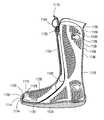
- FIG. 1is a front side perspective view of an embodiment of a circumferential walker according to the present disclosure
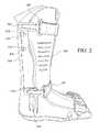
- FIG. 2is a side view of the embodiment of FIG. 1 ;
- FIG. 3is an alternate side view of the embodiment of FIG. 1 ;
- FIG. 4is a partially exploded schematic view of the embodiment of FIG. 1 ;
- FIG. 5is a schematic view of an alternate strap configuration for use with the embodiment of FIG. 1 ;
- FIG. 6is a schematic view of an alternate strap configuration for use with the embodiment of FIG. 1 ;
- FIG. 7is side perspective view of a variation of the embodiment of FIG. 1 utilizing the multi-loop strap adjuster shown in FIG. 4 ;
- FIG. 8is a partial sectional view of one of the straps shown in FIG. 7 ;
- FIG. 9is a side perspective view of another variation of the embodiment of FIG. 1 utilizing an alternate quick connecting strap configuration
- FIG. 10is a side perspective view of a locking element of FIG. 9 ;
- FIG. 11is a cross-sectional view along plane 11 - 11 of the locking element of FIG. 8 ;
- FIG. 12is a close-up isolated perspective view of a connecting assembly of FIG. 9 ;
- FIG. 13is a perspective view of a strap of FIG. 9 ;
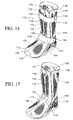
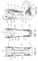
- FIG. 14is a perspective view of an embodiment of a hinged circumferential walker in accordance with the present disclosure.
- FIG. 15is a perspective view of the walker of FIG. 14 with the straps removed for clarity;
- FIG. 16is an expanded perspective view of the dorsal and posterior shells of the walker of FIGS. 14 and 15 with the straps removed;
- FIG. 17is a side view of the posterior shell shown in FIGS. 14 and 15 with the straps removed;
- FIG. 18is a side cross-sectional view of the posterior shell shown in FIGS. 14 and 15 with the straps removed;
- FIG. 19is a partial side cross-sectional view of an embodiment of the hinge between the dorsal shell and posterior shell of the walker of FIGS. 14 and 15 ;
- FIG. 20is a side view showing the hinge action between the dorsal shell and posterior shell of the walker of FIGS. 14 and 15 with the straps removed;
- FIGS. 21 and 22are left and right side views of the walker of FIG. 14 showing the straps and buckle and strap retaining assemblies;
- FIG. 23is a rear view of the walker of FIGS. 14 and 15 with the straps removed;
- FIG. 24is a rear cross-sectional view of the walker of FIGS. 14 and 15 with the straps removed;
- FIG. 25is a perspective view of a variation of the posterior shell of FIG. 14 ;
- FIG. 26is a bottom view of the posterior shell of FIG. 25 ;
- FIG. 27is a perspective view showing the bladders and padding of a variation of the walker of FIG. 14 ;
- FIG. 28is a top view of the bladders of FIG. 27 ;
- FIG. 29is a side view of the posterior shell, bladders, and dorsal shell of the variation shown in FIG. 27 ;
- FIG. 30is a top view of a variation of the bladders shown in FIGS. 27-28 ;
- FIG. 31is a perspective view of a further variation of the bladders for use in a circumferential walker
- FIG. 32is a top view of a variation of the bladders shown in FIG. 31 ;
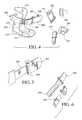
- FIG. 33is a perspective view of a buckle assembly for use with the various embodiments of a walker described herein;
- FIG. 34is a perspective view of the buckle assembly of FIG. 33 shown in an open or release configuration
- FIG. 35is a rear view of the buckle assembly shown in FIG. 33 ;
- FIG. 36is a close up view of an eyelet for use with the various embodiments of a walker described herein to connect the buckle assembly shown in FIGS. 33-35 thereto;
- FIG. 37is a partial rear view of a variation of a posterior shell and expansion mechanism for use with a hinged circumferential walker in accordance with the present disclosure
- FIG. 38is a partial cross-sectional view of the posterior shell of FIG. 37 ;
- FIG. 39is a partial front view of a variation of a dorsal shell, pump assembly, and valve assembly for use with a hinged circumferential walker in accordance with the present disclosure
- FIG. 40is a partial cross-sectional view of the dorsal shell of FIG. 39 ;
- FIG. 41is a partial perspective view of another variation of a dorsal shell for use with a hinged circumferential walker in accordance with the present disclosure
- FIG. 42is a partial perspective view of a variation of a hinge for use with a hinged circumferential walker in accordance with the present disclosure
- FIG. 43is a partial perspective view of another variation of a hinge for use with a hinged circumferential walker in accordance with the present disclosure.
- FIG. 44is a partial cross-sectional view of another variation of a hinge for use with a hinged circumferential walker in accordance with the present disclosure.
- FIG. 45is a partial perspective view of another variation of a hinge for use with a hinged circumferential walker in accordance with the present disclosure.
- FIG. 46is a partial perspective view of another variation of a hinge for use with a hinged circumferential walker in accordance with the present disclosure.
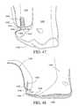
- FIG. 47is a partial perspective view of another variation of a hinge for use with a hinged circumferential walker in accordance with the present disclosure.
- FIG. 48is a partial cross-sectional view of the arrangement shown in FIG. 47 ;
- FIG. 49is a partial perspective view of another variation of a hinge for use with a hinged circumferential walker in accordance with the present disclosure.
- FIG. 50is a partial cross-sectional view of the arrangement shown in FIG. 49 ;
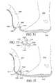
- FIG. 51is a partial cross-sectional side view of another variation of a hinge for use with a hinged circumferential walker in accordance with the present disclosure
- FIG. 52is a partial cross-sectional side view of another variation of a hinge for use with a hinged circumferential walker in accordance with the present disclosure
- FIG. 53is an expanded partial cross-sectional side view of a variation of the hinge shown in FIG. 52 ;
- FIG. 54is a perspective view of another embodiment of a circumferential walker in accordance with the present disclosure.
- FIG. 55is an expanded view of the components of the circumferential walker shown in FIG. 54 ;
- FIG. 56is a perspective view showing a strapping configuration for use with the circumferential walker shown in FIG. 54 ;
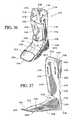
- FIG. 57is a side view of the posterior and plantar shell components of the circumferential walker shown in FIG. 54 ;
- FIG. 58is a rear view of the posterior and plantar shell components of the circumferential walker shown in FIG. 54 ;
- FIG. 59is a front view of the posterior and plantar shell components of the circumferential walker shown in FIG. 54 ;
- FIG. 60is a rear view of the dorsal shell component of the circumferential walker shown in FIG. 54 ;
- FIG. 61is a front view of a pump assembly for use with the circumferential walker shown in FIG. 54 ;
- FIG. 62is a cross-sectional view of the pump assembly shown in FIG. 61 ;
- FIG. 63is a front view of a liner for use with the circumferential walker shown in FIG. 54 .
- Exemplary embodiments of an orthopedic deviceare provided for use in stabilizing and supporting the lower leg, foot, and ankle. Features that are provided on one side of the device can easily be provided on the other side of the device. In this manner, it is intended that the exemplary embodiments of the orthopedic device described herein may be used on either right or left lower legs, with any appropriate reconfiguration of components that is deemed necessary for the proper fit and function of the device for the purpose of supporting and stabilizing either the left or right lower leg.
- quick release strap mechanismsmay be used to provide ease of tightening the device.
- Exemplary quick release strap mechanismsare described in U.S. Pat. No. 7,198,610, granted April 2007, commonly owned, and herein incorporated in the entirety by reference.
- the exemplary embodiments of the disclosureare adapted for supporting and stabilizing the lower leg of human beings, and may be dimensioned to accommodate different types, shapes and sizes of human joints and appendages.
- Exemplary materials and configurations for components of the orthopedic deviceare described in detail in U.S. Pat. Nos. 5,078,128, granted January 1992, 5,329,705, granted July 1994, 5,378,223, granted Jan. 3, 1995, 5,464,385, granted November 1995, and 5,761,834, granted June 1998, all assigned to Royce Medical Co. and all incorporated herein in the entirety by reference. Additional exemplary configurations and materials are described in detail in U.S. Pat. No. 7,303,538, granted December 2007, assigned to ⁇ ssur hf, and incorporated herein in the entirety by reference.
- the term “dorsal”has its ordinary meaning and refers to the top surfaces of the foot, ankle and foreleg or shin.
- the term “plantar”has its ordinary meaning and refers to a bottom surface, such as the bottom of a foot.
- proximalhas its ordinary meaning and refers to a location that is closer to the heart than another location.
- distalhas its ordinary meaning and refers to a location that is further from the heart than another location.
- the term “posterior”also has its ordinary meaning and refers to a location that is behind or to the rear of another location.
- the term “anterior”has its ordinary meaning and refers to a location that is ahead of or to the front of another location.
- the terms “rigid,” “flexible,” and “resilient”may be used herein to distinguish characteristics of portions of certain features of the orthopedic device.
- the term “rigid”is intended to denote that an element of the device is generally devoid of flexibility. Within the context of support members or shells that are “rigid,” it is intended to indicate that they do not lose their overall shape when force is applied, and in fact they may break if bent with sufficient force.
- the term “flexible”is intended to denote that features are capable of repeated bending such that the features may be bent into retained shapes or the features do not retain a general shape, but continuously deform when force is applied.
- the term “resilient”is used to qualify such flexible features as generally returning to an initial general shape without permanent deformation. As for the term “semi-rigid,” this term is used to connote properties of support members or shells that provide support and are free-standing, however such support members or shells may have some degree of flexibility or resiliency.
- FIGS. 1-3An exemplary embodiment of a circumferential lower leg walker 300 is shown in FIGS. 1-3 .
- this embodimentincludes complementary dorsal 302 and posterior 304 shells that are selectively engageable with each other in order to provide easy access to the interior of the device for ease of donning and doffing the device, in particular for donning and doffing the device onto an injured limb.
- the walker 300is configured in an essentially two-piece or one-piece construction to provide a sleek and low profile device for use in stabilizing and supporting the lower leg and includes quick connect tightening mechanisms that provide tightening of the walker about the lower leg. Numerous advantages are obtained from such a configuration, such as lower weight, and less opportunity for the device to catch on external objects or clothing. Any weight savings will be a substantial benefit, as a user must swing the mass of the walker, along with the leg, through the gait cycle. Additionally, the ease with which the tightening mechanisms tighten the walker will aid users who may have trouble manipulating numerous and more complicated strap arrangements which require individual straps to be threaded through D-rings or other similar retention members. In particular, elderly or infirm persons will be able to properly tighten the walker with ease.
- the walker 300includes a semi-rigid, or substantially rigid shell configuration that is formed to support and surround the lower leg, foot, and ankle of a user.
- the shell configurationcan extend from the foot and ankle up along the shin and tibia of the lower leg to a desired point below the knee joint.
- Exemplary suitable materials for forming the shellscan include metals, such as aluminum, carbon, composite materials, such as carbon fiber/epoxy composites, glass fiber/epoxy composites, or suitable plastic materials, such as thermoplastic or thermosetting polymers, fiber reinforced plastic, molded chopped fibers, or any other suitable material.
- Other exemplary materialsinclude, but are not limited to, nylons, glass filled nylon, polypropylenes, vinyls, polyvinyl chlorides, high density polyethylene, epoxies, urethanes, and polyesters.
- the shell configurationincludes a unitary dorsal shell 302 , a posterior shell 304 , and side shell portions 310 extending along the lateral and medial sides of an outsole 312 .
- the side shell portions 310may extend around the anterior of the walker 300 to define a toe protector portion.
- the outsole 312can be formed with suitable tread or other friction enhancing characteristics, and to provide the appropriate rocker sole type response associated with lower leg walkers. Any suitable material may be utilized to form the outsole 312 .
- the clearance holes 314can be formed in any of the shell portions and have any suitable size and/or shape.
- some or all of the clearance holescan be filled with a liner or spacer fabric to provide aerated cushioning for the foot within the walker.
- a liner or spacer fabricto provide aerated cushioning for the foot within the walker.
- Exemplary spacer materialsare described in detail in U.S. publication nos. 2006/0135902, published June 2006, and 2007/0185425, published August 2007, both incorporated herein in the entirety by reference.
- Such a spacer fabriccan provide additional comfort and a proper fit of the walker 1 .
- each of the dorsal and posterior shells 302 , 304includes wing portions 306 , 308 that extend from the respective shell portions towards the opposed shell portion.
- the wing portions 306 , 308wrap around the leg in order to enclose and support the leg.
- the dorsal shell wing portions 306extend generally towards the posterior of the walker 300 and the posterior shell wing portions 308 generally extend towards the anterior of the walker 300 , such that corresponding dorsal and posterior wing portions generally overlap each other when the shells are brought together in a closed configuration.
- the wing portions 306 , 308can also serve as anchor points for quick connect straps.
- eyelets 316are formed in the wing portions 308 of the posterior shell 304 and in the side shell portions 310 for selectively receiving and retaining a protruding portion of a strap 320 or buckle assembly 322 .
- the eyelets 316have a larger sized section for receiving a head 326 of a protruding portion 324 of a strap or buckle assembly, and a reduced size section that forms a seat 318 .
- the seat 318can be in the form of a slot for engaging a reduced size section 328 of a protruding portion 324 of a strap or buckle assembly.
- the buckle assemblies 322can be constructed in a similar configuration and function in a similar manner as described in U.S. Pat. No. 7,198,610, incorporated by reference above.
- one end of a strap 320is selectively securable to the posterior shell 304 via engagement of a protruding portion 324 on the strap end with an eyelet 316 and seat 318 formed in the dorsal shell.
- a similar protruding portion 324is formed on a buckle assembly 322 for selective engagement with an eyelet 316 and seat 318 formed in the opposed side of the posterior shell 304 .
- Multiple eyelets 316can be formed along the posterior shell 304 and/or the side shell portions 310 for either use with additional straps 320 or to provide alternative locations for the existing straps 320 .
- Exemplary connectors and receiver portionsare described in detail in U.S. publication nos.
- the second end of the strap 320includes a hook portion 332 and a loop portion 334 for selective engagement with each other in a manner understood by a skilled artisan.
- the hook portion 332 and the loop portion 334are configured such that the hooks of the hook portion 332 can releasably engage the loops of the loop portion 334 .
- the second end of the strap 320can be inserted through a receiving loop 330 on the buckle assembly 322 and folded over and releasably secured to itself in order to set the strap length.
- a multi-loop strap adjuster 342shown in isolation in FIG. 4 , and in FIGS. 7 and 8 , can be used to provide the desired length adjustment of the straps.
- the setting of the strap lengthis done with both the strap 320 and the buckle assembly 322 engaged with the respective seats 318 and the buckle closed. In this manner, the length of the strap need only be set once, and from this initial setting, the strap can be tightened and loosened via opening and closing of the buckle assembly 322 , and/or disengaging the protruding portions 324 of the strap 320 and/or buckle assembly 322 from the respective seat 318 and/or eyelet 316 .
- a quick adjusting strapping systemis achieved that allows for quick tightening and loosening of the straps for entry and removal of the lower leg, ankle, and foot from the walker 300 .
- At least two straps 320are arranged to cross from opposed sides of the posterior shell 304 over the dorsal shell 302 for bringing the two shells closer together for tightening the walker around the lower leg, ankle, and foot.
- FIGS. 1-4An additional strap 320 , having a slightly different configuration, is shown in FIGS. 1-4 as crossing over the dorsal aspect of the foot and dorsal shell 302 in the region of the toes of the foot.
- the strap 320 in the toe region of the footis similar to the other straps, with the exception of an additional eyelet 316 and seat 318 formed in a connecting element 336 .
- the protruding portion 324 of the buckle assembly 322is selectively engaged with the eyelet 316 and seat 318 formed in the connecting element 336 to provide an additional quick release connection to aid with tightening and loosening of the straps.
- any of the disclosed strap configurationscan be substituted for any other disclosed strap configuration.
- the eyelets 316 and the protruding portions 324can all be made to be interchangeably sized such that the orientation of the straps 320 can be alternated from a leftward to a rightward orientation, and vice versa.
- a manual or automatic self winding element 338can be provided in order to take up excess strap length prior to closing the buckle assembly 322 .
- Such an automatic self winding mechanismcan include a spring loaded element that is tensioned to draw in the excess strap length prior to closing the buckle assembly 322 . In this manner, the additional step of manually adjusting the strap length, as described above, can be eliminated, thus further easing the donning and doffing of the walker, and the tightening of the straps.
- a protruding portion 324can be attached to the second end of the strap for selective engagement with an excess strap retention slot 340 formed in the dorsal 302 or posterior 304 shells. Once the length of the strap has been adjusted, the excess strap length at the second end of the strap can be prevented from excessive movement or flapping by engaging the protruding portion 324 attached to the second end of the strap with the excess strap retention slot 340 . Thus, inadvertent loosening of the strap can be prevented.
- FIGS. 7 and 8a further variation of a circumferential walker 400 utilizing a multi-loop strap adjuster 442 in place of hook and loop portions on the strap 420 is shown in FIGS. 7 and 8 .
- the walker 400is constructed in the manner discussed above with a dorsal shell 402 , a posterior shell 404 , side shell portions 410 , and an outsole portion 412 .
- each of the straps 420are anchored at a first end to the walker 400 along the posterior shell 404 via connecting elements 436 , which can be permanently fixed to, or integrally molded with the posterior shell 404 .
- the strapsmay alternatively be removably attached in a manner discussed above or below.
- the second ends 446 of the straps 420are looped through a receiving loop 430 of a buckle assembly 422 , wound around the segments 444 of the multi-loop strap adjuster 442 , and secured to the strap 420 itself via threading, ultrasonic welding, or any other suitable permanent or non-permanent attachment method.
- a protruding portion 424 of the buckle assembly 422is removably secured to an eyelet and seat formed in the posterior shell 404 , as shown in FIGS. 1-4 and discussed in detail above.
- the buckle assembly 422can be removably attached to the posterior shell 404 in any suitable manner previously discussed.
- the multi-loop strap adjuster 442can be manipulated via sliding along the main portion of the strap 420 to adjust the overall strap length, similarly to the methods previously discussed.
- the length of the straps 420need only be adjusted once, and subsequent engagement and disengagement of the straps 420 to tighten the walker 400 around the lower leg, ankle, and foot are accomplished via the quick connect structure of the buckle assemblies 422 , which are removably connected to the posterior shell 404 .
- This configurationprovides quicker and easier donning and doffing of the walker 400 for all users and in particular for infirm or elderly persons.
- the strapscan be set once by a clinician in a controlled setting to a specified tightness such that the patient does not need to further adjust the straps outside of the presence of the clinician.
- a removable and reusable clampthat can only be removed by the clinician can be utilized to engage the straps such that the patient cannot further adjust the length thereof.
- the strapscan also include indicia to track certain settings by way of the length of the strap.
- the strapscan be threaded through slots in the dorsal shell in order to prevent the dorsal shell from migrating along the dorsal aspect of the foot, ankle, and lower leg. Additionally, the straps may be connected to or fed along the interior surfaces of the posterior shell in order to provide a further low profile brace, with even less chance that the straps may inadvertently catch on external objects and become damaged or loosened.
- FIGS. 9-13A further variation of the embodiment of FIGS. 1-4 is shown in FIGS. 9-13 utilizing an alternative quick connecting strap configuration.
- a circumferential walker 500includes a dorsal shell (not shown in order to illustrate other features, see dorsal shells in FIGS. 1-4 and 7 ), a posterior shell 504 , side shell portions 510 , and an outsole 512 .
- the side shell portions 510can wrap around the anterior portion of the walker 500 to form a toe protector portion.
- a number of quick connect strap assembliesare attached to the walker to provide quick and easy tightening of the straps for providing the desired amount of support to the lower leg, ankle, and foot.
- the quick connect strap assembliesalso make donning and doffing the walker easier for all users, in particular infirm or elderly users.
- each strap 520includes a first end having a ratchet or toothed portion 534 , and a second end that carries a buckle assembly 522 .
- the toothed portion 534carries teeth that are oriented in a first direction for corresponding engagement with complementary ratchet or toothed portion 546 in a connecting assembly 536 , which carries teeth that are oriented in a second, opposed direction to the teeth on the first end of the strap 520 .
- the connector assembly 536is shown in FIGS. 9 and 12 and includes the aforementioned toothed portion 546 , a connecting element 538 (generally in the form of a plate element) pivotally attached to the connector assembly 536 at pivot point 540 , and a gap or slot 544 for receiving the excess strap at the first end of the strap 520 .
- the first, toothed end 534 of the strap 520is inserted under the connecting element 538 via the gap or slot 544 .
- the connecting element 538acts as a lever that pivots about the pivot point 540 and includes an actuation surface or actuation point 542 , which can be actuated via the application of pressure to rotate the connecting element 538 about the pivot point 540 in order to increase the size of the gap or slot 544 .
- This actuation of the connecting element 538can aid with inserting the first toothed end 534 of the strap 520 into the gap or slot 544 , or to release the engagement of the toothed portion 534 of the strap 520 with the complementary shaped toothed portion 546 of the connecting assembly 536 .
- the connecting assembly 536can be integrally formed with the posterior 504 and side 510 shell portions, or it can be separately formed and attached to the posterior 504 and side 510 shell portions in any suitable manner, such as ultrasonic welding or the use of adhesives.
- the second end of the strap 520carries a buckle assembly 522 that includes a pivoting portion 530 that pivots about the end of the strap 520 at pivot point 532 .
- the pivoting portionalso includes a first locking protruding portion 524 and a second nose protruding portion 526 , each carried along one surface thereof.
- the buckle assembly 522is configured to selectively engage a locking element 514 , which is shown in FIGS. 9-11 .
- the locking element 514can be integrally formed with the posterior 504 and side 510 shell portions, or it can be separately formed and attached to the posterior 504 and side 510 shell portions in any suitable manner, such as ultrasonic welding or the use of adhesives.
- the locking element 514includes nose 516 and locking 518 hooks that provide selective engagement for the corresponding and complementary shaped first locking protruding portion 524 and a second nose protruding portion 526 carried on the buckle assembly 522 .
- the userplaces the lower leg into the interior space of the walker 500 defined between the dorsal and posterior 504 shells. Then, the first toothed ends 534 of the straps 520 are inserted a short distance into the gap or slot 544 of the connecting assemblies 536 to engage the straps 520 therewith. Next, the first locking protruding portion 524 and the second nose protruding portion 526 carried on the buckle assemblies 522 are inserted and engaged with the nose 516 and locking 518 hooks of the locking elements 514 such that the pivoting portions 530 are engaged with the locking elements 514 in a flush manner.
- first toothed ends 534 of the straps 520are further inserted into the gap or slot 544 of the connecting assemblies 536 in order to provide the appropriate amount of tightening in order to provide the desired amount of support and stabilization to the lower leg, ankle, and foot.
- first toothed ends 534 of the straps 520can be further inserted into the gap or slot 544 of the connecting assemblies 536 prior to engaging the pivoting portions 530 with the locking elements 514 . If such a step causes the straps 520 to be too tight, the straps 520 may be subsequently loosened a desired amount by actuating the connecting element 538 to release the straps 520 in order to achieve the desired amount of tightening and support.
- the strap lengthscan thus be adjusted once, and subsequent donning and doffing of the walker 500 does not require readjustment of the strap lengths, but merely engagement of the pivoting portions 530 with the locking elements 514 to provide a quick connecting strap assembly.
- the dorsal and posterior shell configurations utilizing the quick connect strap configurationsprovide low profile walkers that ease donning and doffing of the walkers, and also eases tightening of the straps for adjustment.
- Additional featuressuch as inflatable liners with integrally attached pumps, which can provide compression therapy and/or aid with properly fitting the walker to the lower leg, a foam midsole to control heel strike and roll over, and or a fabric exterior covering for the shell portions or a sleep cover accessory to aid with preventing undesired contact with the hard surfaces of the walker may also be provided.
- the midsolecan be formed with different materials or geometries to control heel strike, toe off, and energy return.
- An integrated adjustable heel platform or wedgecan also be provided.
- the shell portionsmay be formed from appropriately resilient materials or have particular resilient portions that allow the shell portions to better conform to the geometry of the user's lower leg.
- the rigidity and stabilization for the supportare provided via the tightening of the quick connect strap configurations about the resilient portions.
- the hinged circumferential, clam-shell like walker 1100is configured in an essentially two-piece construction to provide a sleek and low profile device for use in stabilizing and supporting the lower leg. Numerous advantages are obtained from such a configuration, such as lower weight, and less opportunity for the device to catch on external objects or clothing. Any weight savings will be a substantial benefit, as a user must swing the mass of the walker, along with the leg, through the gait cycle.
- the walker 1100includes a semi-rigid, or substantially rigid shell configuration as previously described.
- the walker 1100includes a posterior shell 1118 that extends from a posterior side of the lower leg and ankle, along the distal surface of the foot, and terminates in a plantar shell portion 1122 that extends along the plantar surface of the foot.
- the posterior shell 1118includes lateral and medial (first and second) wing portions 1134 that extend partially around the lower leg, ankle, and foot from the posterior shell 1118 to wrap around the leg in order to at least partially enclose and support the lower leg.
- a dorsal shell 1102is correspondingly shaped to the posterior shell 1118 to at least partially surround or enclose the lower leg, ankle, and foot to provide protection, support, and stabilization thereto.
- the walker 1100can thus be formed in a clamshell-like configuration to fully encase and protect the lower leg, ankle, and foot.
- the dorsal shell 1102is formed either in a single piece or in multiple shell portions.
- the dorsal shell 1102includes a proximal shell portion 1104 that is connected to a distal shell portion 1106 via a flexible or resilient portion or hinge connection 1108 .
- the connecting portion 1108may be a flexible or resilient material positioned between the proximal and distal shell portions 1104 , 1106 along the dorsal surface of the ankle and/or foot of a user in order to provide a comfort fit between the walker and the ridge of the foot and ankle.
- This connecting portionmay be formed via overmolding a different material onto the end portions of the proximal and distal shell portions 1104 , 1106 to form a flexible or resilient expansion portion or mechanism.
- the connecting portioncan be formed via a flexible plastic or elastomer, such as, for example, ethylene vinyl acetate (EVA).
- EVAethylene vinyl acetate
- any suitable flexible materialmay be utilized, including silicone or natural or synthetic rubbers.
- Alternative hinge mechanismssuch as pivot pins and sleeves, or piano or butterfly hinges, can also be used.
- the connecting portion 1108will reduce or eliminate the formation of a pressure point along the dorsal surface of a user's lower leg, ankle, or foot. Further, due to the flexible nature or resiliency of the connecting portion, when the dorsal shell 1102 is closed around the user's lower leg, ankle, or foot, different sized anatomies can be accommodated using the same sized walker 1100 . Additionally, the walker 1100 will automatically expand or contract due to swelling or reduction of swelling of the lower leg, ankle, and foot of a user.
- the proximal portion of the distal shell 1106extends proximally to create a narrow portion of the connecting portion 1108 .
- the distal shell 1106provides a secure point for a strap (discussed below) to extend over for transferring the closing force of the strap through the distal dorsal shell portion 1106 .
- the proximal portion 1104 of the dorsal shell 1102includes a flexible or resilient edge 1110 along the terminal portion thereof.
- the edge 1110can be formed via overmolding as discussed above. The edge 1110 can therefore act as an expansion mechanism to flex to accommodate different sized lower legs of different users. The edge 1110 also reduces or eliminates pressure points along the edge of the dorsal shell 1102 . Therefore, a comfortable fit is achieved for numerous users having different sized anatomies.
- the distal portion 1106 of the dorsal shellincludes a toe cover or protector portion 1112 that is configured to enclose the foot and toes of a wearer and provide protection thereto.
- the anterior portion of the toe cover 1112also includes receiving openings or slots 1114 formed therein to cooperate with one or more projections 1128 formed along an extending toe portion 1126 of an outsole 1124 to form an adjustable hinge point 1130 between the dorsal and posterior shells 1102 , 1118 .
- the projections 1128 and openings 1114are shown to be elongated, any suitable shape can be utilized. Additionally, while a single projection 1128 and opening 1114 is shown at any particular plane, it will be recognized that a plurality of projections 1128 and openings 1114 can be provided at each plane.
- the outsole 1124can be integrally formed or attached along the plantar shell portion 1122 of the posterior shell 1118 , for example, via overmolding as discussed above.
- the outsolecan be formed from any suitable material, for example, a shock absorbing or resilient material.
- two projections 1128are formed along the extending toe portion 1126 . It will be recognized that fewer or more projections can be used to form the adjustable hinge point 1130 .
- the projections 1128are formed with an enlarged portion and a reduced size portion to have a snap configuration to be selectively engaged and disengaged from the receiving openings 1114 .
- four receiving openings 1114are formed in the anterior portion of the toe cover 1112 to selectively receive the two projections 1128 therein in a snap configuration.
- a usercan selectively reposition the projections 1128 in at least three distinct configurations with the openings 1114 to adjust the height of the dorsal shell 1102 with respect to the plantar shell portion 1122 (a fourth configuration can be formed by inserting the uppermost projection into the lower most opening).
- the walker 1100can be adjusted to accommodate swelling of the lower leg, foot, and ankle, or to accommodate different sized users.
- different numbers of projections and receiving openingscan be utilized to further adapt the walker 1100 to different anatomies.
- the positions of the projections 1128 and openings 1114can be altered, such that the projections extend from the toe cover 1112 and the openings are formed in the extending toe portion 1126 .
- openings and projectionscan be positioned both on the toe cover 1112 and the extending toe portion 1126 in a suitable corresponding manner.
- Other various configurations of hinges 1130are discussed in detail below.
- a hinge 1130is formed to allow the dorsal shell 1102 to be swung away from the posterior shell 1118 in a clamshell-like manner. Due to the use of two projections 1128 , and the resiliency of the extending toe portion 1126 , the dorsal shell 1102 is biased towards the closed position shown in FIG. 18 , such that the walker 1100 will tend to automatically return to a closed configuration from the open configuration shown in FIG. 20 . This will aid with donning the walker 1100 , especially for infirm users.
- a usercan pull open the dorsal shell 1102 away from the posterior shell 1118 , via the hinge 1130 , to allow insertion of the lower leg, ankle, and foot into the walker 1100 .
- the usercan remove the opening force from the dorsal shell 1102 , which will then tend to return to the closed configuration to enclose the lower leg within the walker 1100 .
- the usercan then utilize a connecting mechanism discussed below to apply pressure and support and to maintain the walker 1100 in the closed configuration.
- each of the dorsal and posterior shells 1102 , 1118include clearance holes 1132 defined therein.
- the clearance holes 1132can be arranged in any suitable pattern. For example, some of the clearance holes 1132 may be arranged in a substantially horizontal orientation and some of the clearance holes 1132 may be arranged to be oriented substantially in the proximal-distal direction. The clearance holes may be oriented in the same or different directions or at the same angle or different angles.
- the clearance holes 1132can also reduce the weight of the walker 1100 . Further, the clearance holes 1132 can act as vents to allow heat and perspiration to pass from inside the walker 1100 to the exterior thereof. Additionally, the clearance holes 1132 may also allow the dorsal and posterior shells 1102 , 1118 to have some resiliency to accommodate swelling of a limb or users having different sizes of lower legs, ankles, and feet.
- additional expansion mechanismsare formed in the posterior shell 1118 to reduce or eliminate pressure points and to accommodate users having different sizes of lower legs, ankles, and feet.
- a flexible or resilient edge and expansion joint 1136is formed along the edges of and between the posterior of the wing portions 1134 .
- the expansion joint 1136can be formed having a larger dimension at the proximal end and tapering down to a smaller dimension at the distal end.
- the expansion joint 1136can be overmolded as discussed above.
- the expansion joint 1136includes a number (any desired) of expansion holes 1138 passing therethrough that can be arranged in any suitable manner.
- the holes 1138can have any desired shape or size and can also act as vents.
- the expansion jointcan expand to accommodate swelling or different sized anatomies, and can reduce or eliminate pressure points. Additionally, since the expansion joint 1136 extends along the posterior of the posterior shell 1118 between the wing portions 1134 , the flexibility or resiliency of the expansion joint, aided by the expansion holes 1138 , allows the proximal or upper portions of the wing portions to expand away from each other to accommodate swelling of the limb or users having different sized calves, without losing rigidity in the sagittal plane (the plane dividing the walker 1100 into medial and lateral sides). Due to the larger proximal end, the expansion joint allows more expansion between the proximal portions of the wing portions 1134 than at distally spaced positions of the wing portions 1134 . The expansion joint and edges 1136 also reduce or eliminate pressure points.
- the thickness of the proximal, anterior portions of the wing portions 1134can also be reduced with respect to the thickness of the rest of the posterior shell 1118 such that the wing portions 1134 may more easily expand to accommodate larger sized calves and lower legs.
- a walker 1100has adjustability and expansion capabilities to accommodate users having different sized anatomies or swelling of the limb, and further to reduce or eliminate pressure points to provide a circumferential walker that has a comfortable fit for many different users.
- the walker 1100is also easy to use due to the quick connecting mechanisms, described in detail below, that allow quick and easy engaging and disengaging of straps to don and doff the walker 1100 .
- the wing portions 1134 of the posterior shell 1118include two pairs of eyelets 1140 that include seats 1142 .
- the eyelets 1140 and seats 1142selectively engage projections on strap retaining assemblies 1144 or buckle assemblies 1148 . In this configuration, with the toe hinge 1130 and a sufficiently rigid distal shell portion 1106 , it is only necessary to use two straps to close and secure the walker 1100 .
- the form of the walkerare more low profile to provide a cleaner appearance and to reduce possible contact with foreign objects, and donning and doffing of the walker is made easier since wearers no longer need to stretch and reach all the way to the anterior portion of the walker to apply a “toe” strap.
- a third “toe” strap, or any desired number of strapscan be provided to add additional compression and support.
- Each of the strap retaining assemblies 1144 or buckle assemblies 1148respectively include a receiving loop or D-ring 1146 , 1150 to receive a looped portion of a strap 1152 therethrough.
- the strapsmay be conventional hook and loop fastening straps to provide adjustability. As discussed in detail below, the strap length need only be adjusted an initial time (or infrequently to accommodate swelling or reduction of swelling of tissues), and each subsequent donning and doffing of the walker 1100 can be achieved utilizing the quick connecting configuration.
- a pump assembly 1154 and a valve assembly 1156are integrated with the dorsal shell 1102 .
- the pump assembly 1154 and valve assembly 1156are connected to bladders discussed in detail below that are retained within the walker 1100 to provide additional compression and support to the lower limb of the user.
- the pump assembly 1154can have any suitable configuration and may include a resilient or flexible diaphragm having an inlet (which may be a one-way inlet) and a one-way outlet to transfer air from the exterior of the pump to the bladders. Any available manual or electric pump may also be utilized or integrated into the walker 1100 .
- the valve assembly 1156may be a pressure release valve having single or selectable flow paths. Any available release valve and/or selector valve may be used, for example a push button release valve.
- the walker 1100may have structures designed to selectively strengthen the dorsal or posterior shells 1102 , 1118 in a specific direction.
- the dorsal shell 1102can include a reinforcing ridge 1116 that extends generally longitudinally along both lateral and medial sides thereof.
- the posterior shell 1118can include a reinforcing ridge 1120 positioned to the posterior of the eyelets 1140 and oriented generally in the proximal-distal direction thereof.
- the reinforcing ridges 1116 and 1120can also enhance the low profile form of the walker.
- the reinforcing ridges 1116can further provide additional support for engaging the straps 1152 to provide sufficient support and stabilization to the lower leg of the user.
- FIGS. 25 and 26A variation of a posterior shell 1160 for use with a hinged circumferential walker is shown in FIGS. 25 and 26 .
- the posterior shell 1160has generally the same configuration as previously described, including a plantar shell portion 1162 .
- An indentation or groove 1164is provided along the medial-lateral axis of a proximal surface 1166 of the plantar shell portion 1162 .
- the indentation or groove 1164can extend along the entire length of the plantar shell portion 1162 or over only a portion thereof.
- the indentationmay act as a guide for an inflation tube for bladders, as will be discussed in detail below, such that the inflation tube will not be compressed to cause blockage thereof.
- the posterior shell 1160also includes wings 1174 , as described above. Eyelets 1176 and seats 1178 are provided in the shell wings 1174 to selectively anchor and retain buckle assemblies and strap retaining assemblies. In this variation, three sets of eyelets 1176 and seats 1178 are positioned in the shell wings 1174 so that three straps can be used to tighten and close the walker. It will be recognized that any desired number of sets of eyelets can be provided to accommodate any desired number of straps.
- the posterior shell 1160 and wings 1174also include clearance holes 1172 to add to the low profile form, to reduce weight, to provide venting of heat and perspiration, and to provide some resiliency to the posterior shell 1160 and wings 1174 in the same manner as discussed above.
- the clearance holes 1172may be arranged in any suitable configuration, as previously discussed.
- each seat 1178has associated therewith a buckle rotation restriction groove 1180 .
- the buckle rotation restriction groove 1180cooperatively engages with a protrusion on the buckle assembly or strap retaining assembly to limit the amount that the straps can move.
- the strapsare maintained in position on the walker to provide the appropriate amount of stabilization and support to the user's lower leg.
- the posterior shell 1160also includes reinforcing ridges 1182 positioned in the posterior of the shell and extending in the proximal-distal direction.
- the reinforcing ridges 1182function in the same manner as previously discussed.
- an expansion joint and resilient or flexible edge 1184is positioned between the posterior of the wing portions 1174 and extending in the proximal-distal direction.
- the expansion joint 184includes expansion openings 1186 that are horizontally oriented and which provide the same function as the expansion holes 1138 discussed above.
- the expansion openings 1186can decrease in length from the proximal end to the distal end of the expansion joint 1184 corresponding to the tapered shape of the expansion joint 184 .
- the plantar shell portion 1162also includes a distal surface 1168 .
- Protruding ribbing 1170may be formed on the distal surface 1168 in a length-wise and/or cross-wise manner to create wells, and thus to provide additional support and reinforcement to the toe-off area of the walker.
- Such ribbing 1170can be provided to the plantar shell portion of any posterior shell disclosed herein to provide additional support and reinforcement to the toe-off area of the walker.
- the protruding ribbingcan extend over the entire length of the distal surface 1168 , or over any desired portion thereof.
- the walkeris constructed in any suitable manner as discussed herein and includes a posterior shell 1190 having a plantar shell portion 1192 , and a correspondingly shaped dorsal shell 1194 .
- the bladderscan be inflated or deflated via associated inflation ports or integrally carried pumps.
- the inflation port or pumpmay be integrally carried in a clearance hole of the walker shells.
- a single pumpcan be provided to inflate one or more bladders simultaneously or individually to different pressures, or each bladder may be provided with an associated pump.
- the pumpsare attached or carried by the walker so that they are not easily misplaced. Further, the pumps or inflation ports can be configured to be usable with a fluid or liquid to provide hot and/or cold therapy.
- the inflatable bladderscan also be configured to be ventilated by having slits passing through welded portions of the bladders.
- the welded portionscan be used to create chambers within the bladders, and the use of more welded portions provides more chambers, as well as more slits to enable greater ventilation.
- the medial and lateral bladders 1196are generally shaped to correspond to the medial and lateral side portions of the posterior shell 1190 .
- the dorsal bladder 1198is generally shaped to correspond to the dorsal shell 1194 .
- the medial and lateral bladders 1196each include a bulged portion 1206 that is arranged to be located in the posterior portion of the walker. The bulged portions 1206 fill in the space around the Achilles tendon so that the lower leg will fit snugly within the walker, and so that the ankle is securely locked in position.
- the bladder shapesare further optimized to focus compression where it is needed and uniform compression is provided to all areas of the anatomy where the bladders provide compression.
- the medial, lateral, and dorsal bladders 1196 , 1198are connected via a connecting portion 1200 that extends from one end of the dorsal bladder 1198 to a central portion of the medial and lateral bladders 1196 .
- the connecting portion 1200extends from the dorsal bladder 1198 at the dorsal shell hinge portion and along the plantar shell portion 1192 under the arch and plantar surface of the foot (an indentation or groove of the type shown in FIG. 25 can be used to prevent blocking of the connecting portion 1200 ).
- all of the bladders 1196 , 1198can be simultaneously inflated via the inflation tubing 204 connected to an opposed end of the dorsal bladder 1198 .
- the inflation tubingis connected to a pump, such as described above.
- the bladders 1196 , 1198can be formed of two sheets of air impervious plastic material that is welded around the edges to create air chambers therebetween. Perspiration wicking material can be applied to the surfaces of the bladders 1196 , 1198 that are configured to contact the wearer's anatomy.
- the bladders 1196 , 1198can be secured to the interior of the walker in any suitable manner, such as, for example, via adhesive, hook and loop fasteners, or snap fasteners.
- welds and/or holes 1202are arranged in the bladders 1196 , 1198 to serve a number of functions.
- the welds 1202 in the bladders 1196 , 1198can serve to direct airflow within the bladders and also to provide heat and perspiration wicking channels along the surfaces of the bladders 1196 , 1198 .
- foam or other types of padding 1208can be provided to reduce pressure points along the interior of the walker.
- the padding 1208can be any suitable padding and can be secured to the interior of the walker in any suitable manner, such as via adhesive, hook and loop fasteners, or snap fasteners.
- FIG. 30A further variation of a bladder configuration for use with a hinged circumferential walker is shown in FIG. 30 .
- Medial and lateral bladders 1210are connected to a dorsal bladder 1212 via a connecting portion or tubing 1214 .
- the medial and lateral bladders 1210 and the dorsal bladder 1212are shaped in a similar manner as discussed above.
- the medial and lateral bladders 1210include the bulged portions 1220 as discussed above to surround and support the area around the Achilles tendon.
- the dorsal bladderincludes an inflation tube 1218 connected at one end thereof.
- the dorsal bladder 1198includes longitudinally extending openings 1222 that provide venting for heat and perspiration.
- the welds that form openings 1222also form air flow channels and chambers within the dorsal bladder 1198 to guide airflow from the dorsal bladder 1198 to the connecting portion 1214 .
- the connecting portion 1214extends along a proximal surface of a plantar shell portion under the arch and plantar surface of the foot and connects to one end of either the medial or lateral bladder 1196 .
- the bladders 1196 , 1198can be simultaneously inflated or deflated via the use of a pump assembly and valve assembly as previously discussed.
- the medial and lateral bladders 1196also include a central welded portion 1216 that extends along the bladders 1196 to provide a heat and perspiration dissipation channel.
- the welded portion 1216extends to a position near an opening or vent 1222 in the bladders 1196 so that heat and perspiration can rise along the welded portion 1216 to be vented from the openings 1222 .
- the openings 1222 in the bladders 1196are appropriately shaped to provide breathability to the bladders 1196 without degradation of compression being applied to the lower limb.
- FIGS. 31 and 32A further variation of a bladder assembly for use with a hinged circumferential walker 1230 is shown in FIGS. 31 and 32 .
- the walker 1230includes a dorsal shell 1232 and a posterior shell 1234 .
- a pump assembly 1236is integrated into the proximal portion of the dorsal shell 1232 and is connected to a selector/release valve assembly 1238 , which is also integrated into the dorsal shell 1232 .
- the selector/release valve assembly 1238is connected to medial and lateral bladders 1242 , and a dorsal bladder 1244 via independent inflation tubing 1240 .
- the selector/release valve assembly 1238can be used to selectively inflate or deflate different bladders to provide more or less compression to different portions of the anatomy.
- the inflation tubing 1240 for the medial and lateral bladders 1242extends along medial and lateral sides of the posterior shell 1234 to one end of the medial and lateral bladders 1242 .
- the dorsal 1244 and medial and lateral bladders 1242have a similar shape as previously discussed.
- the medial and lateral bladders 1242include the bulged portions 1248 to surround and support the Achilles tendon area of the lower leg, as discussed above.
- each of the bladders 1242 , 1244include weld portions or openings 1246 to act as airflow guides and heat and perspiration dissipation channels or venting openings as previously discussed.
- medial and lateral bladders 1242 and a dorsal bladder 1244are illustrated, some of these bladders may be removed, or additional bladders may be added in order to concentrate compression onto specific areas of the anatomy.
- an additional planter bladdercan be positioned under the arch and/or plantar surface of the foot in order to provide arch support.
- the buckle assembly 1250 shown in FIGS. 33-36has the same configuration as the buckle assembly 1148 mentioned above.
- the buckle assembly 1250includes a main portion 1252 connected via a first hinge 1264 to a clamping portion 1266 .
- the clamping portion 1266is connected via a second hinge 1272 to a strap retaining portion 1274 .
- the main portion 1252includes ergonomically shaped finger indents or grips 1254 that enhance the wearer's ability to grip and attach the main portion 1252 to the shell of the walker.
- the main portion 1252also includes a protruding portion 1256 extending from a surface thereof.
- the protruding portion 1256includes a head portion 1258 and a reduced size portion 1260 .
- the head portion 1258 and a reduced size portion 1260are configured to engage the eyelet 1280 and seat 1282 in the posterior shell wing 1278 ( FIG. 36 ) in a recognized manner.
- the buckle assemblycan be selectively attached and detached from the posterior shell wing 1278 .
- a reduced dimension or locking portion 1286is formed between the eyelet 1280 and the seat 1282 .
- the reduced size portion 1260 of the protruding portionis sized to be slightly larger than the locking portion 1286 , such that when the reduced size portion 1260 is seated within the seat 1282 , the locking portion 1286 provides a snap engagement thereof to prevent inadvertent removal of the reduced size portion 1260 and the buckle assembly 1250 from the seat 1282 .
- the main portion 1252further includes a buckle rotation restriction projection 1262 extending therefrom.
- the projection 1262is configured to engage the buckle rotation restriction groove 1284 in the posterior shell wing 1278 ( FIG. 36 ) in the manner previously discussed to prevent rotational movement of the straps. In this manner, a user can easily manipulate the straps and buckle assemblies 1250 , which stay in position while a user attempts manipulation.
- the clamping portion 1266includes an actuation portion or tab 1268 that can be manipulated by a user to clamp and unclamp the clamping portion 1266 via selective rotation about the first hinge 1264 .
- an engaging portion or snap locking projection 1270is formed on the clamping portion 1266 to selectively engage the main portion 1252 .
- the clamping portion 1266can be clamped and unclamped from the main portion 1252 to provide quick tightening and loosening of straps once the straps have been initially tightened.
- the strap retaining portion 1274includes a receiving loop or D-ring 1276 to receive a looped end of a strap therethrough. Clamping or unclamping of the clamping portion 1266 is transmitted through the strap retaining portion 1274 via relative rotation at the second hinge 1272 . Thus, Clamping or unclamping of the clamping portion 1266 is also transmitted to the strap connected to the strap retaining portion 1274 .
- the strapsneed only to be tightened once initially (or infrequently to accommodate swelling or reduction of swelling of tissues) and the buckle assemblies 1250 can be utilized to provide quick connecting and tightening or loosening of the straps.
- the strapsare initially loosened and the buckle assemblies 1250 are removed from the walker to allow the dorsal shell of the walker to be rotated away from the posterior shell.
- an opening between the dorsal and posterior shellsallows a wearer to position their lower limb within the walker.
- the dorsal shellwill tend to close when the opening force is removed.
- the buckle assemblies 1250are attached to the eyelets and seated in the posterior shell in the unclamped configuration.
- the clamping portions 1266are then clamped and the straps are initially tightened to provide the appropriate amount of support and stabilization to the lower leg.
- the clamping portions 1266are unclamped, and the buckle assemblies 1250 are removed from the seats and eyelets of the posterior shell. Then, the user can pivot the dorsal shell away from the posterior shell to remove the lower leg from the walker.
- the userneed only insert the lower leg within the walker, attach the buckle assemblies 1250 to the posterior shell, and clamp the clamping portions 1266 .
- the buckle assemblies 1250to the posterior shell
- clamp the clamping portions 1266there is no need to adjust the strap tension each time the user dons the walker. Accordingly, a more convenient and easy to use configuration is provided to assist users that may have trouble manipulating numerous straps every time they need to don and doff the walker.
- the configurations of the protruding portion 1256 , head portion 1258 , reduced size portion 1260 , strap retaining portion 1274 , and buckle rotation restriction projection 1262 of the buckle assembly 1250can also be utilized in the strap retaining assembly 1144 discussed above to selectively connect the strap retaining assembly 1144 to the posterior shell wing 1278 .
- the buckle assemblies 1250 and the strap retaining assemblies 1144are interchangeable from one side of the walker to the other. Accordingly, the straps and buckle assemblies 1250 can be easily oriented for manipulation by right or left handed users. Additionally, the straps can be completely removed from the walker for any desired reason, such as replacement of components, or for storage.
- FIGS. 37 and 38A variation of an expansion joint 1294 for use with a circumferential walker is shown in FIGS. 37 and 38 .
- a posterior shell 1290generally constructed in accordance with the principles discussed above is shown in FIG. 38 .
- the posterior shell 1290includes medial and lateral wing portions 1292 that define an opening therebetween in the proximal section of the posterior portion of the posterior shell 1290 .
- An expansion joint 1294generally of the type described above is situated in the opening between the wing portions 1292 .
- the wing portions 1292include proximal edges that carry flexible or resilient expansion joint edges 1296 to accommodate various sized anatomies, or swelling, and/or to reduce or eliminate pressure points, in a manner previously discussed.
- the expansion joint 1294includes a proximal portion 1298 , a distal portion 1300 , and a reinforcing portion 1302 located in the proximal portion 1298 .
- the expansion joint 1294has a larger dimension in the proximal portion 1298 and tapers to a smaller dimension in the distal portion 1300 , in a manner discussed above.
- the reinforcing portion 1302has a similarly configured tapering shape from the proximal portion to the distal portion.
- the expansion joint 1294also includes expansion holes or openings 1304 arranged horizontally, or with a slight angled orientation in the proximal-distal direction.
- the expansion holes or openings 1304extend in the proximal-distal direction between the edges of the expansion joint 1394 and between the reinforcing portion 1302 and the edges of the expansion joint 1394 .
- the expansion holes or openings 1304function as described above.
- Expansion struts 1306are defined between the expansion openings 1304 .
- the expansion struts 1306have a smaller thickness than the remaining portions of the expansion joint 1294 , such as the reinforcing portion 1302 .
- the expansion struts 1306can more easily expand (in a manner similar to a rubber band) to accommodate various sized anatomies (for example, a larger calf size), or swelling, and/or to reduce or eliminate pressure points, in a manner previously discussed.
- FIGS. 39 and 40A further variation of a dorsal shell 1310 for use with a circumferential walker is shown in FIGS. 39 and 40 .
- the dorsal shell 1310generally constructed in accordance with the principles discussed above is shown FIG. 39 .
- the dorsal shell 1310includes a proximal edge portion 1312 that is shaped to engage the shin of a wearer.
- a living hinge 1314is provided along the proximal edge portion 1312 to allow the proximal edge portion 1312 to flex or bend about the living hinge 1314 .
- the living hinge 1314is a thin section of material between the proximal edge portion 1312 and the main section of the dorsal shell 1310 .
- the living hinge 1314has a thickness that is less than the thickness of the rest of the dorsal shell 1310 or the proximal edge portion 1312 . Since the living hinge 1314 has a smaller thickness than the dorsal shell 1310 or the proximal edge portion 1312 the proximal edge portion 1312 is able to bend or flex with respect to the dorsal shell 1310 around the living hinge 1314 .
- the specific construction of the living hinge 1314is dependent upon the desired amount of flexing, and the direction of flexing.
- the actual thickness and shape of the living hinge 1314is dependent upon the thickness of the dorsal shell 1310 and the proximal edge portion 1312 .
- the living hinge 1314may therefore be formed in any suitable shape, size and orientation, in order to provide the desired flexing characteristics.
- the living hinge 1314may be provided by a recessed line or groove along the anterior surface of the proximal portion of the dorsal shell 1310 .
- the length of the living hinge 1314may extend substantially along the entire proximal edge portion 1312 .
- the length of the living hinge 1314may have any suitable length. The actual process of forming the living hinge 1314 will be understood by a skilled artisan.
- the dorsal shell 1310also includes a pump receiving opening 1316 .
- the pump receiving opening 1316includes a tapered ridge 1318 extending around the periphery of the opening 1316 .
- a flexible bulb type pump 1320is inserted through the pump receiving opening 1316 .
- the pump 1320includes a flexible lip 1322 extending around the periphery of the pump 1320 for cooperative engagement with the tapered ridge 1318 to retain the pump 1320 with the pump receiving opening 1316 of the dorsal shell 1310 .
- the pump 1320includes an inlet 1324 that allows air to flow into the body of the pump 1320 , but is selectively closed when the pump is actuated so that air does not flow out of the pump 1320 through the inlet.
- the pump 1320also includes an outlet 1326 , opposed to the inlet 1324 , and retaining a one-way outlet valve 1326 therein, such that actuation of the pump causes air to flow from the inlet 1324 through the one-way outlet valve 1326 towards the bladders (not shown but described in detail above).
- a push button release valve 1330is incorporated with the pump 1320 to release the pressure within the bladders.
- An actuation surface 1332 of the release valve 1330is connected to a valve stem 1336 and is biased toward the unactuated position via a biasing element or spring 1334 .
- the valve stem 1336passes through a valve seat 1340 and carries a sealing element 1342 thereon for selective engagement with the valve seat 1340 to open and close the valve 1330 .
- the valve stem 1336is engaged with a guide post 1338 to guide the reciprocating action of the valve stem 1336 within the valve 1330 .
- the valve 1330passes through an opening 1344 in the dorsal shell 1310 to be carried thereon.
- the opening 1344includes an anti-rotation cutout 1346 which engages an anti-rotation ridge or projection formed on the body of the valve 1330 to prevent rotation of the valve 1330 within the opening 1344 .
- FIG. 41A further variation of a dorsal shell 1476 for use with a circumferential walker 1470 is shown in FIG. 41 .
- the walker 1470 shown in FIG. 41includes a posterior shell 1472 having lateral and medial side portions 1474 and a dorsal shell 1476 .
- the dorsal shellhas proximal 1478 and distal 1482 portions connected to each other via a flexible or hinge portion 1480 .
- the distal shell portion 1482is connected at an anterior portion thereof to an outsole 1486 (or a planter shell portion) via a hinge 1488 of any type described herein.
- the distal dorsal shell portion 1482also includes lateral and medial flap portions 1484 extending distally therefrom.
- the flap portions 1484provide mechanisms to align the dorsal shell 1476 with the posterior shell 1472 during opening and closing of the walker 1470 about the hinge 1488 .
- the flap portions 1484also aid to retain the distal dorsal shell portion 1482 with the plantar shell of the posterior shell 1472 .
- FIGS. 42-50Additional variations of hinge configurations for use with a hinged circumferential walker are shown in FIGS. 42-50 .
- a dorsal shell 1350includes a toe cover portion 1352 and an extension portion 1354 extending therefrom.
- a living hinge 1356is formed between the extension portion 1354 and the dorsal shell 1350 to allow the extension portion 1354 to flex or bend with respect to the dorsal shell 1350 .
- the extension portion 1354also includes receiving openings 1358 to selectively engage, in a manner previously discussed, flexible protrusions 1368 positioned on either a plantar shell portion 1362 of a posterior shell 1360 or in a cutout 1366 in an outsole 1364 .
- the cutout 1366 of the outsole 1364can create a receiving space for the extension portion 1354 to be received therein to maintain a low profile device.
- the flexible protrusions 1368can be positioned and formed within the cutout 1366 of the outsole 1364 to create a receiving space for the extension portion 1354 to be received therein to maintain a low profile device.
- the location of the flexible protrusions 1368 and receiving openings 1358is alternated from that shown in FIG. 42 , such that the flexible protrusions 1368 are formed on the extension portion 1354 and the receiving openings 1358 are formed in the cutout 1366 .
- the living hinge 1356 of the extension portion 1354allows the dorsal shell 1350 to rotate with respect to the posterior shell 1360 so that the circumferential walker can be opened to allow the wearer to place their lower leg therein.
- the flexible protrusions 1368 and receiving openings 1358can be provided in the plurality to allow the wearer to adjust the spacing between the dorsal shell 1350 and the posterior shell 1360 in order to accommodate swelling or different size anatomies. While four protrusions and receiving openings are shown, it will be recognized that more or fewer protrusions and receiving openings can be utilized.
- FIG. 44A further variation of a hinge configuration is shown in FIG. 44 .
- the walkerincludes a dorsal shell 1370 with a toe cover portion 1372 .
- Receiving openings 1374are positioned in the distal anterior portion of the toe cover portion 1372 .
- a posterior shell 1376has a plantar shell portion 1378 with an extension portion 1380 extending from the anterior portion thereof and an outsole 1386 formed thereon.
- a living hinge 1382is formed between the extension portion 1380 and the plantar shell portion 1378 to allow the extension portion 1380 to flex or bend about the plantar shell portion 1378 .
- At least one flexible protrusion 1384is formed on the extension portion 1380 to selectively engage at least one of the receiving openings 1374 .
- the position of the flexible protrusion 1384 and the receiving openings 1374can be alternated.
- the engagement between the flexible protrusion 1384 and the receiving openings 1374can be used to adjust the size of the walker.
- the living hinge 1382allows the dorsal shell 1370 to rotate about the planter shell portion 1378 to allow a user to easily don and doff the walker.
- the hingecan be formed by using fasteners.
- the dorsal shell 1390includes a toe cover portion 1392 with a first connector portion 1394 formed at the anterior distal portion thereof.
- the posterior shell 1396includes an outsole 1398 formed thereon.
- the outsole 1398includes an extension portion 1400 formed at the anterior portion thereof and carries a second connector portion 1402 .
- the first connector portion 1394is located on an exterior surface of the dorsal shell 1390 and the second connector portion 1402 is located on an interior surface of the extension 1400 of the outsole 1398 . It will be recognized that these locations may be alternated.
- the first and second connector portions 1394 , 1402are configured to allow selective and adjustable connection therebetween. Exemplary configurations can include hook and loop fastening material, or a plurality of snap connections. It will be recognized that either the first or second connector portions 1394 , 1402 can be formed from hook material and the other formed from loop material, and vice versa.
- the hook and loop materialcan be attached to the dorsal shell 1390 and extension 1400 of the outsole 1398 via adhesive or other suitable mechanism. Alternatively, the hook material and loop fabric can be directly injection molded with or into the respective dorsal shell 1390 and extension 1400 of the outsole 1398 . Exemplary methods of molding hook material into a shell are described in detail in U.S. Pat. Nos. 5,368,549, granted Nov. 29, 1994, 5,656,226, granted Aug. 12, 1997, and RE37,338, granted Aug. 21, 2001, each incorporated herein in the entirety by reference.
- first and second connector portions 1394 , 1402can be disengaged and engaged to alter the distance between the dorsal shell 1390 and the posterior shell 1396 to accommodate swelling or different size anatomies. Further, when the first and second connector portions 1394 , 1402 are engaged, the dorsal shell 1390 can rotate with respect to the posterior shell 1396 to allow a wearer to easily don and doff the device.
- FIG. 46A further variation of a hinge arrangement is shown in FIG. 46 .
- a dorsal shell 1410includes a first strap receiving slot or D-ring 1416 at an anterior distal portion thereof.
- a posterior shell 1412includes an outsole 1414 formed thereon that has a second strap receiving slot or D-ring 1418 at an anterior portion thereof.
- a strap 1420has one end looped over and secured to itself at the first strap receiving slot 1416 . The strap is subsequently threaded through the second strap receiving slot 1418 and threaded up along and through a strap guide 1422 on the proximal surface of the dorsal shell 1410 .
- the straphas a first connector portion 1424 at the end thereof for selective engagement with a second connector portion 1426 on the proximal surface of the dorsal shell 1410 .
- the first and second connector portions 1424 , 1426can be formed as discussed above from hook and loop fasteners to allow selective engagement therebetween and adjustment of the spacing between the dorsal shell 1410 and the posterior shell 1412 to accommodate swelling or different size anatomies. Further, due to the flexibility of the strap, the dorsal shell 1410 can rotate with respect to the posterior shell 1412 to allow a wearer to easily don and doff the device.
- the strapcan be secured at a first end to the outsole, threaded through the D-ring on the dorsal shell, and secured to a bottom surface of the outsole.
- a cutout on the outsolesimilar to the cutout described above, can be provided to allow the strap to be secured therein to provide a low profile sole.
- a further variation of a hinge configurationis shown in FIGS. 47 and 48 .
- a dorsal shell 1430includes a toe cover portion 1432 that has as receiving opening 1434 formed at the anterior distal portion thereof.
- a posterior shell 1436includes a plantar shell portion 1438 and an outsole 1446 formed thereon.
- An extension portion 1440extends from the plantar shell portion 1438 at an anterior portion thereof.
- a living hinge 1442is formed between the extension portion 1440 and the plantar shell portion 1438 in a manner discussed above.
- the extension portion 1440can be formed as a separate piece that is attached to the plantar shell portion 1438 in any suitable manner.
- the extension portion 1440includes a ratchet structure 1444 formed on one surface thereof.
- the extension portion 1440is arranged to be received through the receiving opening 1434 to connect the dorsal shell 1430 to the posterior shell 1436 so that the dorsal shell 1430 can rotate with respect to the posterior shell 1436 to allow a wearer to easily don and doff the device.
- the ratchet structure 1444can easily slide within the receiving opening 1434 to adjust the spacing between the dorsal shell 1430 and the posterior shell 1436 .
- the extension portion 1440flexes or bends about the living hinge 1442 and the ratchet structure 1444 engages the edge of the receiving opening 1434 to maintain the dorsal shell 1430 in engagement with the posterior shell 1436 .
- the dorsal shell 1450includes a toe cover portion 1452 and an extension portion 1454 extending from an anterior distal portion thereof.
- a living hinge 1456is formed between the toe cover portion 1452 and an extension portion 1454 to allow the extension portion 1454 to flex or bend about the toe cover portion 1452 .
- a ratchet structure 1458is formed on a surface of the extension portion 1454 . It will be recognized that the extension portion 1454 can be formed as a separate piece that is connected to the dorsal shell 1450 in any suitable manner.
- a posterior shell 1460has a plantar shell portion 1462 having an outsole 1466 formed thereon.
- a receiving opening 1464is formed at an anterior portion between the plantar shell portion 1462 and the outsole 1466 .
- the extension portion 1454is configured to extend into the receiving opening 1464 , and functions in a manner previously discussed to allow adjustment of the spacing between the dorsal shell 1450 and the posterior shell 1460 to accommodate swelling and different size anatomies.
- FIG. 51Another variation of a hinge for use with a hinged circumferential walker is shown in FIG. 51 .
- the dorsal shell 1490includes a toe cover portion 1492 that has receiving openings 1494 formed therein.
- the posterior shell 1496has an outsole 1498 formed thereon or attached thereto.
- the outsole 1498includes an extension portion 1500 extending from an anterior portion thereof. Projections 1502 extend from the anterior surface of the extension portion 1500 for selective engagement with the receiving openings 1494 of the dorsal shell 1490 .
- This configurationprevents accidental disengagement of the projections 1502 from the receiving openings 1494 due to the forward migration of the wearer's foot within the walker during the gait cycle. Since the projections 1502 are formed on the anterior surface of the extension portion 1500 , even if the wearer's foot migrates all the way to the anterior portion of the walker, the foot will not cause the projections 1502 to accidentally disengage from the receiving openings 1494 .
- the dorsal shell 1510includes a toe cover portion 1512 that has receiving openings 1514 formed therein.
- the posterior shell 1516has an outsole (or plantar shell portion) 1518 formed thereon or attached thereto.
- the outsole 1518includes first and second extension portions 1520 , 1524 extending from an anterior portion thereof.
- Projections 1522extend from the anterior surface of the first extension portion 1520 for selective engagement with the receiving openings 1514 of the dorsal shell 1490 and with receiving openings 1526 formed in the second extension portion 1524 .
- This configurationprovides additional assurance that the projections 1522 will not accidentally disengage from the receiving openings 1514 in the dorsal shell 1510 , by providing the second extension portion 1524 covering the receiving openings 1514 .
- the hinge shown in FIG. 53includes an outsole (or plantar shell portion) 1530 having first and second extension portions 1532 , 1538 extending from an anterior portion thereof.
- Each of the first and second extension portions 1532 , 1538includes at least one projection 1534 , 1542 extending therefrom and at least one receiving opening 1536 , 1540 formed therein.
- the projections 1534 , 1542are respectively formed on the anterior and posterior surfaces of the first and second extension portions 1532 , 1538 .
- the dorsal shell(not shown, see FIG. 52 ) includes a plurality of receiving openings. As will be understood, the receiving openings of the dorsal shell are sandwiched between the projections 1534 , 1542 and receiving openings 1536 , 1540 of the first and second extension portions 1532 , 1538 , such that the projections 1534 , 1542 extend through the receiving openings in the dorsal shell to retain the dorsal shell in connection with the posterior shell.
- This configurationprovides yet another mechanism to ensure that the dorsal shell does not accidentally disengage from the posterior shell of the walker.
- hinge configurationsthat allow selective adjustment of the spacing between the dorsal shell and the posterior shell can be provided to accommodate swelling and different size anatomies.
- a variation of a circumferential walker 2100is configured in an essentially two-piece construction to provide a lightweight, sleek, and low profile device for use in stabilizing, immobilizing, and supporting the lower leg. Numerous advantages are obtained from such a configuration, as discussed above.
- the walker 2100includes a semi-rigid, or substantially rigid shell configuration as previously described.
- the walker 2100includes a posterior shell 2120 that extends from a posterior side of the lower leg and ankle, along the distal surface of the foot, and terminates in a plantar shell portion 2144 that extends along the plantar surface of the foot.
- the posterior shell 2120includes lateral and medial (first and second) wing portions 2122 that extend partially around the lower leg, ankle, and foot from the posterior shell 2120 to wrap around the leg in order to at least partially enclose and support the lower leg.
- the posterior shell 2122also defines side shell portions 2310 , 2311 extending along the lateral and medial sides of the plantar shell portion 2144 , and being spaced apart by the plantar shell portion 2144 so as to define a clearance 2312 between each of the side shell portions 2310 , 2311 .
- the posterior shell 2122also defines a closed-ended heel portion 2314 and an open-ended toe portion 2316 .
- the side shell portions 2310terminate before the toe end 2316 , leaving an open section 2320 at the toe end 2316 .
- the plantar shell portion 2144defines a bottom or outer surface 2318 that secures adjacently to the outsole 2148 .
- a dorsal shell 2102is generally complementary shaped to the posterior shell 2120 to at least partially surround or enclose the lower leg, ankle, and foot to provide protection, support, and stabilization thereto.
- the walker 2100can thus be formed in a general configuration to fully encase and protect the lower leg, ankle, and foot.
- the dorsal shell 2102is formed either in a single piece or in multiple shell portions.
- the dorsal shellcan include a raised reinforcing ridge 2110 running along the proximal surface thereof and may also include clearance holes 2112 in accordance with the discussion above.
- the dorsal shell 2102also includes a pump assembly receiving opening 2106 which can be configured in a similar manner as previously discussed, or may simply be provided as a clearance opening through the dorsal shell 2102 . The position of the pump assembly receiving opening 2106 can be varied to accommodate numerous locations a pump assembly.
- the dorsal shell 2102includes a proximal shell portion 2104 that is connected to a distal shell portion 2108 via a flexible or resilient portion or hinge connection 2114 .
- the proximal and distal shell portions 2104 , 2108connect to the hinge connection 2114 at narrowed central portions 2324 , 2326 .
- a gap 2322is at least formed between the proximal shell portion 2104 and the hinge connection 2114 outside of the narrowed central region 2324 .
- the connecting portion 2114may be formed as a flexible or resilient material positioned between the proximal and distal shell portions 2104 , 2108 and encompassing a connecting shell portion between the proximal and distal shell portions 2104 , 2108 .
- This connecting portionmay be formed via overmolding a different material over the connecting shell portion to form a flexible or resilient expansion portion or mechanism, in a manner discussed above.
- the connecting portion 2114can be positioned so as to be located between the anatomical portion of the wearer and a strap used to retain the walker 2100 thereon. In this manner, the possibility of pressure points being caused by such a strap is greatly reduced or eliminated.
- the connecting portion 2114can include holes 2216 passing therethrough, which may function as ventilation holes and/or which may increase the flexibility of the connecting portion 2114 .
- the connecting portion 2114can include a gap 2118 formed along one surface thereof.
- the presence of the gap 2118will help to reduce or eliminate the formation of a pressure point along the dorsal surface of a user's lower leg, ankle, or foot.
- the connecting portion 2114due to the flexible nature or resiliency of the connecting portion 2114 , and the additional presence of the gap 2118 , when the dorsal shell 2102 is closed around the user's lower leg, ankle, or foot, different sized anatomies can be accommodated using the same sized walker 2100 .
- the walker 2100will automatically expand or contract due to swelling or reduction of swelling of the lower leg, ankle, and foot of a user.
- the gap 2118is not a required feature, and the connecting portion 2114 can accomplish the above functions without the use of such a gap.
- the posterior shell 2120has generally the same configuration as discussed above, including clearance holes 2134 , and reinforcing or strengthening structures 2142 .
- Such reinforcing or strengthening structures 2142can extend over a portion of the height of the posterior shell 2120 , as shown in FIG. 59 , or over substantially the entire height of the posterior shell 2120 .
- the posterior shell 2120can include a flexible or compliant proximal edge 2124 , which can be overmolded. A portion of the flexible or compliant edge 2124 can also be trimmed to accommodate users having shorter legs, in order to avoid the creation of pressure points from the edge being too large. This allows the user to adjust the fit of the walker 2100 , without the creation of hard edges.
- strap slots 2136are positioned in the proximal portion of the posterior shell 2120 for receiving a strap 2140 therein.
- the strap 2140can include suitable connecting structures, for example corresponding hook and loop fasteners at respective ends thereof so that the ends of the strap can be connected to each other.
- a loop or D-ringcan be attached at one end of the strap 2140 so that the strap can be looped through the loop or D-ring and attached to itself via suitable fasteners.
- Strap connecting portions 2138such as reduced thickness portions and/or holes for rivet connections are also provided in the posterior shell wings 2122 to selectively anchor and retain strap assemblies.
- connection points for the strapsare pivotable and can allow some rotation or adjustability of the straps.
- two sets of strap connecting portions 2138are positioned in the posterior shell wings 2122 so that two straps can be used to tighten and close the walker.
- any desired number of sets of strap connecting portionscan be provided to accommodate any desired number of straps.
- loops or D-ringscan be attached, for example via loops of fabric, to the strap connecting portions 2138 at both lateral and medial sides, along with a strap 2140 connected at one end to the strap connecting portion 2138 .
- the other end of the strap 2140can be looped through one or both of the loops or b-rings and connected to itself via suitable fasteners, such as hook and loop fasteners.
- a strap configurationis shown in FIG. 56 , without the dorsal shell 2102 present. It can be seen that the ends of the straps 2140 can be attached at the anterior portion of the walker 2100 . Since the straps 2140 are positioned at the front of the walker 2100 this configuration allows easier access to the straps 2140 to allow wearers to adjust the fit of the walker 2100 .
- the ends of the strapscan be connected in any suitable manner, such as hook and loop, or snap fasteners.
- the straps 2140are disengaged and the dorsal shell 2102 , which is positioned under the straps when the walker 2100 is worn, is removed to allow the wearer to place the lower leg, ankle, and foot within an interior space defined among the dorsal shell 2102 , the posterior shell 2120 , and the plantar shell portion 2144 .
- the dorsal shell 2102can be positioned along the dorsal surfaces of the lower leg, ankle, and foot and the straps 2140 can be engaged over the dorsal shell 2102 to retain the dorsal shell in place to provide the desired amount of support and stabilization to the lower leg, ankle, and foot.
- other suitable attachment mechanismssuch as quick connect strapping mechanisms discussed herein, can be used to secure the dorsal shell 2102 in place.
- the plantar shell portion 2144includes reinforcing, connecting, or guide ridges 2146 positioned along the distal surface thereof for guiding placement of and/or providing connection for an outsole 2148 . Additionally, reinforcing ribs or structures can be provided along the proximal surface of the plantar shell portion 2144 if needed.
- the outsole 2148can be formed in any manner previously discussed, either as a separate element or integrally with the plantar shell portion 2144 .
- the outsole 2148can include a heel protector 2154 and a toe protector portion 2150 that is configured to cover and protect the toes of a wearer when the walker 2100 is worn.
- the toe protector 2150extends around a section of the side shell portions 2310 , 2311 of the posterior shell at the toe end 2316 . However, if necessary to accommodate larger sized anatomies, or to accommodate swollen toes, the toe protector portion 2150 can be trimmed down or trimmed completely away.
- the outsole 2148can also include cushioning structures 2152 formed therein to provide appropriate biomechanical functions.
- the cushioning structures 2152can be configured to adjust heel strike and rollover properties of the walker 2100 .
- the outsole 2148can be formed as a full rocker bottom to provide the associated benefits to the wearer's gait.
- a flexible or resilient edge 2124can be formed along the edges of the posterior shell 2120 of the wing portions 2122 to accommodate different sized anatomical portions of different wearers.
- expansion joints 2126can be provided between a posterior portion of the posterior shell 2120 and the posterior shell wings 2122 .
- the expansion joints 2126can be similarly formed and function in a manner as discussed above.
- the expansion joints 2126allow the posterior shell 2120 to automatically stretch or compress to accommodate different sized wearers.
- the expansion joints 2126can be formed having a larger dimension at the proximal end and tapering down to a smaller dimension at the distal end.
- the expansion joints 2126can include a bridge 2130 spanning across the expansion joint 2126 , although such a bridge is not necessary. The function of the bridge 2130 will be discussed in more detail below.
- the expansion joints 2126can be overmolded as previously discussed and can includes a number (any desired) of expansion holes 2128 passing therethrough that can be arranged in any suitable manner.
- the expansion holes 2128can have any desired shape or size and can also act as vents. Additionally, the overmolded sections between the expansion holes 2128 can be thinner than the overmolded portions that contact the edges of the posterior shell and wing portions 2120 , 2122 . The reduced thickness sections can thus allow easier stretching of the expansion joints 2126 .
- the expansion joints 2126allow the posterior shell wing portions 2122 to expand away from each other or contract towards each other in order to accommodate swelling or different sized anatomies, such as larger or smaller calves, and can reduce or eliminate pressure points.
- the walker 2100can accommodate swelling of the limb or users having different sized calves, without losing rigidity in the sagittal plane (the plane dividing the walker 2100 into medial and lateral sides).
- the expansion jointallows more expansion between the proximal portions of the wing portions 2122 than at distally spaced positions of the wing portions 2122 .
- the overmolded portion of the expansion joints 2126can be cut or torn to allow the wing portions 2122 to be able to move further from the posterior portion of the posterior shell 2120 . Due to the flexibility or compliance of the overmolded portion of the expansion joints 2126 , this portion is relatively easy to cut or tear, and does not leave sharp edges that can cause injury.
- the expansion holes 2128can act as stopping points for the cut or tear, so that the cut or tear does not extend further than is desired. In this manner, incremental adjustments can be achieved.
- the cutting or tearing of the overmolded portion of the expansion joints 2126can extend all the way to the bridge 2130 positioned in the expansion joint 2126 , and the bridge 2130 can then act as a stopping point.
- overmolding 2132can be provided on the bridge 2130 in the interior space of the walker 2100 . If even more expansion is needed, the bridge 2130 can be cut or broken, and the overmolding 2132 serves the function of preventing sharp edges from the cut or broken bridge 2130 .
- the bridge 2130can include a weakened or frangible portion to aid with cutting or breaking the bridge, in a manner that will be recognized by a skilled artisan.
- the expansion holes 2128 positioned below the bridge 2130can also be cut, similarly as discussed above. In this manner, there is a large amount of adjustability provided in the walker 2100 , such that many wearers having different sizes and shapes of anatomical portions can utilize a generally one size fits all walker.
- a liner 2172 having inflatable bladders and foam paddingcan be provided as an interface between the wearer's anatomy and the walker 2100 . It will be recognized that additional cushioning, such as provided by insoles or separate heel cushions positioned behind the Achilles tendon, can also be provided.
- the liner 2172can have any suitable configuration, such as any of those previously discussed, including linked medial and lateral bladders.
- the liner 2712can include a covering material, such as softgood, that can be used to engage hook fasteners positioned on opposed flaps thereof, such that the liner 2172 can be positioned and secured to the lower leg, ankle, and foot of the wearer.
- Additional perspiration wicking material 2178can be positioned on or in the liner 2172 .
- the liner 2172can also include a strategically placed spacer element 2176 that can aid with heat and moisture dissipation.
- the spacer element 2176can be positioned along the dorsal aspect of the liner 2172 above the foot of the wearer.
- the liner 2172can include inflatable bladders, which can be inflated or deflated to accommodate different sized anatomies or to accommodate swelling, and to provide a desired amount of support and stabilization to the lower leg, ankle, and foot.
- the bladderscan be inflated via an inflation tube, which is connected to a pump assembly 2156 .
- the pump assembly 2156is connected to the inflation tube, and is carried by the liner 2172 .
- the liner 2172includes a sliding slot 2174 through which the inflation tube can slightly extend. In this manner, the pump assembly 2156 can be slid in the lateral-medial direction.
- the pump assembly 2156can thus be slid in the lateral-medial direction in order to aid with aligning the pump assembly 2156 with the pump assembly receiving opening 2106 in the dorsal shell 2102 .
- donning of the walker 2100is made easier.
- the pump assembly 2156includes an assembly cover 2158 , which is made from any suitable flexible, resilient, or compliant material, and which covers the pump 2164 and release valve 2170 assemblies.
- the assembly cover 2158includes vent openings 2160 to allow air vented from deflating the bladders to pass through the assembly cover 2158 to atmosphere.
- the assembly cover 2158can also include actuation enhancement features 2162 , such as raised portions or ridges, which may be configured in any suitable design, such as a cross or an elongated portion.
- the actuation enhancement features 2162provide features to enhance friction or gripping for allowing the user to more easily actuate the pump 2164 and the release valve 2170 .
- the pump assembly 2156is similarly configured to the pump assembly previously discussed, and includes an inlet valve 2166 , which may be a one-way valve that can also function as a release valve, positioned at one end of the pump 2164 , which may be a diaphragm pump, and a one-way outlet valve 2168 positioned at a second end of the pump 2164 .
- the one-way outlet valve 2168communicates through the release valve 2170 , which can be of any suitable type, including the release valve previously discussed, with the bladder inflation tube for inflating the bladders.
- the remaining features of the pump assembly 2156function in a similar manner as discussed above.
- the pump 2164can be actuated to inflate the bladders therein to provide an appropriate amount of compression, support, and stability to the lower leg, ankle, and foot.
- a highly adjustable circumferential walkerwhich can accommodate a large variation of sizes of anatomies or swelling of the anatomical portions.
- the disclosed embodiments of a circumferential walkerprovide many improvements and allow easy insertion or removal of the lower leg into the walker. Additionally, the quick connect strap tightening mechanisms allow quick and easy tightening of the walker around the lower leg in order to provide the necessary support and stabilization of the lower leg, ankle, and foot. Accordingly, the disclosed embodiments of a circumferential walker are easier to don and doff, which will be advantageous to numerous users, including the elderly or infirm.
- the size of the disclosed embodiments and the components thereofcan be adjusted so that different users having different sized legs, ankles, and feet may benefit from the present design.
- the width, thickness and length of the shells and sole membersmay be varied to accommodate different sized users.
Landscapes
- Health & Medical Sciences (AREA)
- Nursing (AREA)
- Orthopedic Medicine & Surgery (AREA)
- Engineering & Computer Science (AREA)
- Biomedical Technology (AREA)
- Heart & Thoracic Surgery (AREA)
- Vascular Medicine (AREA)
- Life Sciences & Earth Sciences (AREA)
- Animal Behavior & Ethology (AREA)
- General Health & Medical Sciences (AREA)
- Public Health (AREA)
- Veterinary Medicine (AREA)
- Orthopedics, Nursing, And Contraception (AREA)
Abstract
Description
Claims (7)
Priority Applications (6)
| Application Number | Priority Date | Filing Date | Title |
|---|---|---|---|
| US12/563,386US8506510B2 (en) | 2008-05-15 | 2009-09-21 | Circumferential walker |
| US13/307,795US9333106B2 (en) | 2008-05-15 | 2011-11-30 | Circumferential walker |
| US13/951,933US9492301B2 (en) | 2008-05-15 | 2013-07-26 | Circumferential walker |
| US14/212,936US9220621B2 (en) | 2008-05-15 | 2014-03-14 | Circumferential walker |
| US14/792,729US9468553B2 (en) | 2008-05-15 | 2015-07-07 | Circumferential walker |
| US14/856,871US10064749B2 (en) | 2008-05-15 | 2015-09-17 | Circumferential walker |
Applications Claiming Priority (5)
| Application Number | Priority Date | Filing Date | Title |
|---|---|---|---|
| US7174708P | 2008-05-15 | 2008-05-15 | |
| US7182908P | 2008-05-20 | 2008-05-20 | |
| US9901708P | 2008-09-22 | 2008-09-22 | |
| US12/466,577US8002724B2 (en) | 2008-05-15 | 2009-05-15 | Circumferential walker |
| US12/563,386US8506510B2 (en) | 2008-05-15 | 2009-09-21 | Circumferential walker |
Related Parent Applications (1)
| Application Number | Title | Priority Date | Filing Date |
|---|---|---|---|
| US12/466,577ContinuationUS8002724B2 (en) | 2008-05-15 | 2009-05-15 | Circumferential walker |
Related Child Applications (2)
| Application Number | Title | Priority Date | Filing Date |
|---|---|---|---|
| US13/307,795ContinuationUS9333106B2 (en) | 2008-05-15 | 2011-11-30 | Circumferential walker |
| US13/951,933ContinuationUS9492301B2 (en) | 2008-05-15 | 2013-07-26 | Circumferential walker |
Publications (2)
| Publication Number | Publication Date |
|---|---|
| US20100234782A1 US20100234782A1 (en) | 2010-09-16 |
| US8506510B2true US8506510B2 (en) | 2013-08-13 |
Family
ID=40792839
Family Applications (7)
| Application Number | Title | Priority Date | Filing Date |
|---|---|---|---|
| US12/466,577Active2029-06-04US8002724B2 (en) | 2008-05-15 | 2009-05-15 | Circumferential walker |
| US12/563,386Active2030-10-13US8506510B2 (en) | 2008-05-15 | 2009-09-21 | Circumferential walker |
| US13/307,795ActiveUS9333106B2 (en) | 2008-05-15 | 2011-11-30 | Circumferential walker |
| US13/951,933ActiveUS9492301B2 (en) | 2008-05-15 | 2013-07-26 | Circumferential walker |
| US14/212,936ActiveUS9220621B2 (en) | 2008-05-15 | 2014-03-14 | Circumferential walker |
| US14/792,729ActiveUS9468553B2 (en) | 2008-05-15 | 2015-07-07 | Circumferential walker |
| US14/856,871Active2030-05-15US10064749B2 (en) | 2008-05-15 | 2015-09-17 | Circumferential walker |
Family Applications Before (1)
| Application Number | Title | Priority Date | Filing Date |
|---|---|---|---|
| US12/466,577Active2029-06-04US8002724B2 (en) | 2008-05-15 | 2009-05-15 | Circumferential walker |
Family Applications After (5)
| Application Number | Title | Priority Date | Filing Date |
|---|---|---|---|
| US13/307,795ActiveUS9333106B2 (en) | 2008-05-15 | 2011-11-30 | Circumferential walker |
| US13/951,933ActiveUS9492301B2 (en) | 2008-05-15 | 2013-07-26 | Circumferential walker |
| US14/212,936ActiveUS9220621B2 (en) | 2008-05-15 | 2014-03-14 | Circumferential walker |
| US14/792,729ActiveUS9468553B2 (en) | 2008-05-15 | 2015-07-07 | Circumferential walker |
| US14/856,871Active2030-05-15US10064749B2 (en) | 2008-05-15 | 2015-09-17 | Circumferential walker |
Country Status (4)
| Country | Link |
|---|---|
| US (7) | US8002724B2 (en) |
| EP (2) | EP3034051B1 (en) |
| CN (1) | CN102026592B (en) |
| WO (1) | WO2009139893A1 (en) |
Cited By (14)
| Publication number | Priority date | Publication date | Assignee | Title |
|---|---|---|---|---|
| USD729393S1 (en) | 2014-03-27 | 2015-05-12 | Ossur Hf | Outsole for an orthopedic device |
| USD742017S1 (en) | 2014-03-27 | 2015-10-27 | Ossur Hf | Shell for an orthopedic device |
| USD744111S1 (en) | 2014-03-27 | 2015-11-24 | Ossur Hf | Orthopedic device |
| US9220621B2 (en) | 2008-05-15 | 2015-12-29 | Ossur Hf | Circumferential walker |
| US9668907B2 (en) | 2013-09-25 | 2017-06-06 | Ossur Iceland Ehf | Orthopedic device |
| US9744065B2 (en) | 2013-09-25 | 2017-08-29 | Ossur Hf | Orthopedic device |
| US9839549B2 (en) | 2013-09-25 | 2017-12-12 | Ossur Iceland Ehf | Orthopedic device |
| US9839548B2 (en) | 2013-09-25 | 2017-12-12 | Ossur Iceland Ehf | Orthopedic device |
| US10058143B2 (en) | 2013-12-12 | 2018-08-28 | Ossur Hf | Outsole for orthopedic device |
| US10391211B2 (en) | 2015-01-26 | 2019-08-27 | Ossur Iceland Ehf | Negative pressure wound therapy orthopedic device |
| US10939723B2 (en) | 2013-09-18 | 2021-03-09 | Ossur Hf | Insole for an orthopedic device |
| WO2024086686A1 (en) | 2022-10-21 | 2024-04-25 | Ossur Iceland Ehf | Pump assembly for an orthopedic device |
| US12156825B2 (en) | 2018-02-02 | 2024-12-03 | Ossur Iceland Ehf | Orthopedic walker |
| US12357488B2 (en) | 2020-10-14 | 2025-07-15 | Darco International, Inc. | Rear entry walker |
Families Citing this family (107)
| Publication number | Priority date | Publication date | Assignee | Title |
|---|---|---|---|---|
| US20040064195A1 (en) | 2002-07-15 | 2004-04-01 | Hugh Herr | Variable-mechanical-impedance artificial legs |
| US8075633B2 (en) | 2003-09-25 | 2011-12-13 | Massachusetts Institute Of Technology | Active ankle foot orthosis |
| US8512415B2 (en) | 2005-03-31 | 2013-08-20 | Massachusetts Institute Of Technology | Powered ankle-foot prothesis |
| US20070123997A1 (en) | 2005-03-31 | 2007-05-31 | Massachusetts Institute Of Technology | Exoskeletons for running and walking |
| US8864846B2 (en) | 2005-03-31 | 2014-10-21 | Massachusetts Institute Of Technology | Model-based neuromechanical controller for a robotic leg |
| US8500823B2 (en)* | 2005-03-31 | 2013-08-06 | Massachusetts Institute Of Technology | Powered artificial knee with agonist-antagonist actuation |
| US11278433B2 (en) | 2005-03-31 | 2022-03-22 | Massachusetts Institute Of Technology | Powered ankle-foot prosthesis |
| US10307272B2 (en) | 2005-03-31 | 2019-06-04 | Massachusetts Institute Of Technology | Method for using a model-based controller for a robotic leg |
| US20070162152A1 (en) | 2005-03-31 | 2007-07-12 | Massachusetts Institute Of Technology | Artificial joints using agonist-antagonist actuators |
| US20060249315A1 (en) | 2005-03-31 | 2006-11-09 | Massachusetts Institute Of Technology | Artificial human limbs and joints employing actuators, springs, and variable-damper elements |
| US10080672B2 (en) | 2005-03-31 | 2018-09-25 | Bionx Medical Technologies, Inc. | Hybrid terrain-adaptive lower-extremity systems |
| US20070043449A1 (en) | 2005-03-31 | 2007-02-22 | Massachusetts Institute Of Technology | Artificial ankle-foot system with spring, variable-damping, and series-elastic actuator components |
| US10842653B2 (en) | 2007-09-19 | 2020-11-24 | Ability Dynamics, Llc | Vacuum system for a prosthetic foot |
| CN102026594B (en) | 2008-05-15 | 2013-12-25 | 欧苏尔公司 | Orthopedic devices utilizing rotary tensioning |
| KR20110074520A (en) | 2008-09-04 | 2011-06-30 | 아이워크, 아이엔씨. | Hybrid Terrain-Adaptive Prosthetic Systems |
| US20110082566A1 (en) | 2008-09-04 | 2011-04-07 | Herr Hugh M | Implementing a stand-up sequence using a lower-extremity prosthesis or orthosis |
| IT1394266B1 (en)* | 2008-10-23 | 2012-06-01 | Zordan | MOLD FOR SAFETY HOLDING MEANS |
| CN104523359B (en) | 2008-12-02 | 2017-06-09 | 欧苏尔公司 | ankle brace |
| CN102333502B (en) | 2009-02-26 | 2014-06-25 | 欧苏尔公司 | Orthopedic devices used to treat the back |
| USD620124S1 (en)* | 2009-09-14 | 2010-07-20 | Ossur Hf | Orthopedic device |
| US8657769B2 (en) | 2009-11-04 | 2014-02-25 | Ossur Hf | Thoracic lumbar sacral orthosis |
| US20120289878A1 (en)* | 2009-11-24 | 2012-11-15 | Schwenn Shannon R | Low profile hip orthosis |
| US20110146032A1 (en) | 2009-12-10 | 2011-06-23 | Ossur Hf | Strapping system |
| CN102892388A (en) | 2010-04-05 | 2013-01-23 | Iwalk股份有限公司 | Controlling torque in a prosthesis or orthosis |
| USD634438S1 (en)* | 2010-06-14 | 2011-03-15 | Ossur Hf | Orthopedic walker |
| US20120000092A1 (en) | 2010-07-01 | 2012-01-05 | Ingvarsson Thorvaldur | Achilles tendon stretching device |
| US9889034B2 (en) | 2010-07-01 | 2018-02-13 | Ossur Hf | Achilles tendon stretching device |
| US9180038B2 (en) | 2010-08-05 | 2015-11-10 | Ossur Hf | Walker having height adjustment and method for doing the same |
| EP2605730B1 (en) | 2010-08-20 | 2015-04-29 | Össur HF | Configurable subshell components in orthopedic devices |
| WO2012096956A1 (en) | 2011-01-10 | 2012-07-19 | Iwalk, Inc. | Powered joint orthosis |
| US20120259430A1 (en) | 2011-01-12 | 2012-10-11 | Zhixiu Han | Controlling powered human augmentation devices |
| US9687377B2 (en) | 2011-01-21 | 2017-06-27 | Bionx Medical Technologies, Inc. | Terrain adaptive powered joint orthosis |
| CN103442669B (en) | 2011-02-10 | 2015-09-16 | 奥索有限责任公司 | For the tightening system of orthopedic goods |
| WO2012125562A1 (en) | 2011-03-11 | 2012-09-20 | Iwalk, Inc. | Biomimetic joint actuators |
| US10863791B2 (en) | 2011-04-07 | 2020-12-15 | Ovation Medical | Removable leg walker |
| US10016326B2 (en) | 2011-06-09 | 2018-07-10 | Molnycke Health Care Ab | Compression device in combination with lower limb protection |
| WO2012177700A2 (en) | 2011-06-20 | 2012-12-27 | Ossur Hf | Orthopedic device, use of orthopedic device and method for producing the same |
| US8574181B2 (en)* | 2011-09-13 | 2013-11-05 | Velocity Medical, Llc | Ankle walker |
| WO2013067407A1 (en) | 2011-11-02 | 2013-05-10 | Iwalk, Inc. | Biomimetic transfemoral prosthesis |
| US9032635B2 (en) | 2011-12-15 | 2015-05-19 | Massachusetts Institute Of Technology | Physiological measurement device or wearable device interface simulator and method of use |
| WO2013106666A1 (en) | 2012-01-13 | 2013-07-18 | Ossur Hf | Spinal orthosis and method for using the same |
| US9572705B2 (en) | 2012-01-13 | 2017-02-21 | Ossur Hf | Spinal orthosis |
| US9221177B2 (en) | 2012-04-18 | 2015-12-29 | Massachusetts Institute Of Technology | Neuromuscular model-based sensing and control paradigm for a robotic leg |
| ITVR20120075A1 (en)* | 2012-04-20 | 2013-10-21 | Fgp Srl | QUICK RELEASE PASSER FOR FIXING ORTHOSES THROUGH BELTS OR SIMILAR |
| WO2013188510A2 (en) | 2012-06-12 | 2013-12-19 | Iwalk, Inc. | Prosthetic, orthotic or exoskeleton device |
| USD703335S1 (en) | 2012-08-03 | 2014-04-22 | Velocity Medical, Llc | Ankle walker shell |
| US9248042B2 (en) | 2012-09-12 | 2016-02-02 | Yessenia Lopez | Dorsal foot splint |
| EP2897559B1 (en) | 2012-09-19 | 2019-03-06 | Ossur HF | Panel attachment and circumference adjustment systems for an orthopedic device |
| US8932245B2 (en) | 2012-11-08 | 2015-01-13 | Tung-Cheng Chen | Ventilative orthopedic boot with an air cushion |
| WO2014116895A1 (en) | 2013-01-24 | 2014-07-31 | Ossur Hf | Orthopedic device for treating complications of the hip |
| US9554935B2 (en) | 2013-01-24 | 2017-01-31 | Ossur Hf | Orthopedic device for treating complications of the hip |
| US10357391B2 (en) | 2013-01-24 | 2019-07-23 | Ossur Hf | Orthopedic device for treating complications of the hip |
| US9795500B2 (en) | 2013-01-24 | 2017-10-24 | Ossur Hf | Orthopedic device for treating complications of the hip |
| USD731070S1 (en) | 2013-01-25 | 2015-06-02 | Vincent A. Benenati | Orthopedic walker |
| US8978693B2 (en)* | 2013-01-28 | 2015-03-17 | Windcatcher Technology LLC | Inflation valve allowing for rapid inflation and deflation of an inflatable object |
| USD693471S1 (en)* | 2013-03-12 | 2013-11-12 | Scott Orthotics, LLC | Ankle-foot orthotic |
| US10449078B2 (en) | 2013-03-15 | 2019-10-22 | Ovation Medical | Modular system for an orthopedic walking boot |
| WO2014144517A1 (en) | 2013-03-15 | 2014-09-18 | Ovation Medical | Orthopedic walking boot with heel cushion |
| US10039664B2 (en) | 2013-03-15 | 2018-08-07 | Ortho Systems | Overmolding for an orthopedic walking boot |
| EP3091945B1 (en)* | 2014-01-10 | 2020-09-09 | Alessandro Barberio | Porous orthopedic or prosthetic support having removable cushioning and scaffolding layers |
| WO2015103708A1 (en) | 2014-01-10 | 2015-07-16 | Alessandro Barberio | Porous orthopedic or prosthetic support having removable cushioning and scaffolding layers |
| CN106029040A (en)* | 2014-02-07 | 2016-10-12 | 拉杰·罗摩克里希纳 | portable compression device |
| US20150237952A1 (en)* | 2014-02-27 | 2015-08-27 | Debra Garriga | Ventilated Wellington Boots |
| WO2015179332A1 (en) | 2014-05-19 | 2015-11-26 | Ossur Hf | Adjustable prosthetic device |
| US9510965B2 (en) | 2014-07-01 | 2016-12-06 | Ortho Systems | Adjustable walking apparatus |
| WO2016007496A1 (en) | 2014-07-10 | 2016-01-14 | Ossur Hf | Versatile orthopedic device |
| WO2016007704A1 (en) | 2014-07-11 | 2016-01-14 | Ossur Hf | Tightening system with a tension control mechanism |
| EP3171830B1 (en) | 2014-07-21 | 2018-07-04 | Ossur Iceland EHF | Achilles heel wedge |
| WO2016025371A1 (en) | 2014-08-12 | 2016-02-18 | Ossur Hf | Achilles tendon stretching device |
| CN105361990A (en)* | 2014-08-25 | 2016-03-02 | 亿莱富国际股份有限公司 | rehabilitation shoes |
| DE102014113363A1 (en)* | 2014-09-17 | 2016-03-17 | Petra Meyer-Clasen | Orthosis, in particular Fußhebeorthese |
| DE102014113366A1 (en)* | 2014-09-17 | 2016-03-17 | Petra Meyer-Clasen | Closure for an orthosis, in particular Fußhebeorthese |
| CN104190071B (en)* | 2014-09-24 | 2016-08-17 | 芜湖天人智能机械有限公司 | Quickly assemble and disassemble leg protectors for rehabilitation training machines, protector manufacturing molds and manufacturing methods |
| EP3200733B1 (en) | 2014-10-01 | 2018-11-28 | Össur Iceland EHF | Support for articles and methods for using the same |
| US10561520B2 (en) | 2015-02-27 | 2020-02-18 | Ossur Iceland Ehf | Spinal orthosis, kit and method for using the same |
| WO2016138215A1 (en) | 2015-02-27 | 2016-09-01 | Ossur Iceland Ehf | Spinal orthosis, kit and method for using the same |
| US11413180B2 (en) | 2015-03-20 | 2022-08-16 | TayCo Brace, LLC | External ankle brace |
| US20160270944A1 (en) | 2015-03-20 | 2016-09-22 | University Of Notre Dame | External ankle brace |
| EP3283020B1 (en)* | 2015-04-17 | 2020-06-03 | Vision Quest Industries Incorporated Dba VQ Orthocare | Orthotic device with snap fit cuff and latch mechanism |
| US12090080B2 (en) | 2015-04-23 | 2024-09-17 | Osteoid Saglik Teknolojileri A.S. | Adaptive three-dimensional orthoses and methods for their manufacture and use |
| EP3285647B1 (en) | 2015-04-23 | 2019-09-25 | Osteoid Saglik Teknolojileri A.S. | Adaptive three-dimensional orthosis and method for its manufacture |
| WO2016210117A1 (en)* | 2015-06-23 | 2016-12-29 | The Regents Of The University Of California | A mechanism for efficient donning and doffing of an exoskeleton |
| US10583027B2 (en)* | 2015-08-28 | 2020-03-10 | Orthomerica Products, Inc. | Orthosis walking boot |
| CN111938891B (en) | 2016-03-15 | 2022-08-05 | 金忠焕 | Leg protector |
| US10609968B2 (en) | 2016-08-17 | 2020-04-07 | Nike, Inc. | Garment having selected stretch zones |
| CN106308993A (en)* | 2016-09-27 | 2017-01-11 | 深圳简单医疗科技有限公司 | Automatic inflation system for medical externally-fixed walking protection equipment |
| US11006693B2 (en) | 2017-01-31 | 2021-05-18 | Jason R. Hanft | Articles of footwear for inhibiting and treating injuries |
| DE102017001596A1 (en) | 2017-02-13 | 2018-08-16 | Tino Jacobi | Support cuff for bone and joint fractures in veterinary medicine with adaptation method of manufacture |
| US11648142B2 (en) | 2017-02-13 | 2023-05-16 | Ossur Iceland Ehf | Orthopedic device, method, and system for making an orthopedic device |
| EP3678613B1 (en) | 2017-09-07 | 2023-08-09 | Össur Iceland EHF | Thoracic lumbar sacral orthosis attachment |
| US11000439B2 (en) | 2017-09-28 | 2021-05-11 | Ossur Iceland Ehf | Body interface |
| USD861180S1 (en) | 2017-10-27 | 2019-09-24 | Foot Defender, LLC | Cam walker |
| USD846130S1 (en) | 2018-01-31 | 2019-04-16 | Ortho Systems | Knee brace |
| CN108186181A (en)* | 2018-02-05 | 2018-06-22 | 南京鼓楼医院 | A kind of portable outer bionic fiber for restoring brain injury patients lower limb function |
| WO2019231864A1 (en)* | 2018-05-26 | 2019-12-05 | The Board Of Trustees Of The Leland Stanford Junior University | Systems and methods for preventing or reducing post-traumatic swelling about the ankle |
| GB2576201B (en)* | 2018-08-09 | 2021-08-04 | Prescription Footwear Ass Ltd | Orthotic device and orthotic methods |
| US11253383B2 (en) | 2018-09-20 | 2022-02-22 | Foot Defender Llc | CAM walker with removable collar |
| US11666471B2 (en)* | 2019-05-13 | 2023-06-06 | Djo, Llc | Walking boot, chafe assembly, protective rim for a push-button release valve and related methods |
| USD979771S1 (en)* | 2019-08-29 | 2023-02-28 | Fung Lead Medical And Sports Co., Ltd. | Rehabilitation shoe |
| CN111436716B (en)* | 2020-04-28 | 2021-07-23 | 中国医学科学院北京协和医院 | A special shoe based on the soles of patients with missing toes |
| USD943754S1 (en)* | 2020-07-13 | 2022-02-15 | Invent Medical Group, S.R.O. | Orthosis |
| WO2022050442A1 (en)* | 2020-09-03 | 2022-03-10 | 서울대학교 산학협력단 | Wearable anchoring device |
| CA3209905A1 (en)* | 2021-03-03 | 2022-09-09 | Ethnocare Inc. | Adjustable overlaying liner-prosthesis interface and corresponding method |
| CN113274185B (en)* | 2021-05-17 | 2022-09-23 | 山东省日照市人民医院 | Lower limb nursing, restraining and fixing device for neurosurgery |
| WO2023278961A1 (en)* | 2021-07-01 | 2023-01-05 | The Uab Research Foundation | Offloading walking boot |
| DE102021006129A1 (en)* | 2021-12-13 | 2023-06-15 | plus medica OT GmbH | Orthopedic technical device and method for manufacturing |
| US20240091042A1 (en)* | 2022-09-19 | 2024-03-21 | Ortho Systems d/b/a Ovation Medical, Inc. | Orthopedic walking boot |
Citations (137)
| Publication number | Priority date | Publication date | Assignee | Title |
|---|---|---|---|---|
| US3464126A (en)* | 1967-10-30 | 1969-09-02 | Vahe B Sarkissian | Shoe with a hinged mechanically adjustable heel |
| US3580248A (en)* | 1968-12-02 | 1971-05-25 | Leighton W Larson | Bivalved cast |
| US3685176A (en) | 1970-07-02 | 1972-08-22 | Marion F Rudy | Inflatable article of footwear |
| US3760056A (en) | 1970-09-23 | 1973-09-18 | Bogert R | Method for custom fitting an inflatable bladder to a wearer{3 s foot |
| US3786805A (en) | 1970-10-06 | 1974-01-22 | Inst Europ De Rech Et D Applic | Splint having inflatable detachable cushions |
| US3792537A (en)* | 1971-02-24 | 1974-02-19 | Rieker & Co Justus | Ski boot |
| DE2341658A1 (en) | 1972-08-23 | 1974-03-07 | Polyair Maschb Gmbh | SKI BOOT |
| US3814088A (en) | 1972-01-12 | 1974-06-04 | E Raymond | Orthopedic boot |
| US3922800A (en) | 1974-07-01 | 1975-12-02 | K 2 Corp | Size adjustable ski boot |
| US3955565A (en) | 1973-12-05 | 1976-05-11 | Johnson Jr Glenn W | Orthopedic apparatus |
| US4045888A (en) | 1976-10-26 | 1977-09-06 | Bruce Oxenberg | Athletic shoe |
| US4057056A (en) | 1976-06-01 | 1977-11-08 | Payton Hugh W | Walking cast |
| US4142307A (en) | 1977-01-07 | 1979-03-06 | Hans Martin | Ski and skating boot |
| FR2399811A1 (en) | 1977-08-08 | 1979-03-09 | Delery Marc | Sports shoe, especially skating boot - has outer thermoplastic shell with protuberances used for guiding flexible cables, tightened by ratchet wheel |
| US4184273A (en) | 1977-09-06 | 1980-01-22 | Scott Usa, Inc. | Boot with hinged upper |
| US4217706A (en) | 1979-07-18 | 1980-08-19 | Vartanian Vincent A | Boot for walking cast |
| US4217893A (en) | 1977-08-01 | 1980-08-19 | Payton Hugh W | Above-the-knee cast |
| US4232459A (en) | 1977-11-02 | 1980-11-11 | Franco Vaccari | Ski boots |
| US4414965A (en) | 1981-05-26 | 1983-11-15 | Mauldin Donald M | Brace for tibial fractures |
| USD272281S (en) | 1981-09-28 | 1984-01-17 | Ballert Orthopedic Corp. | Contracture control orthosis |
| US4446856A (en) | 1981-12-18 | 1984-05-08 | The Langer Biomechanics Group, Inc. | Orthotic device |
| US4494536A (en) | 1982-12-01 | 1985-01-22 | Latenser John F | Foam boot |
| US4505269A (en) | 1983-07-21 | 1985-03-19 | Davies John R | Ankle splint |
| US4550721A (en) | 1983-07-01 | 1985-11-05 | Michel Lorraine M | Foot support |
| US4565017A (en) | 1984-09-28 | 1986-01-21 | Ottieri Enterprises | Ski boot |
| US4572169A (en) | 1984-04-03 | 1986-02-25 | Kenneth D. Driver | Removable lower leg brace |
| US4587962A (en) | 1984-02-08 | 1986-05-13 | United States Manufacturing Company | Tibia/ankle orthosis |
| EP0095396B1 (en) | 1982-05-21 | 1986-08-27 | Guy Salort | External upright position and walking apparatus for the lower-limbs motorically handicapped |
| US4620378A (en) | 1984-05-30 | 1986-11-04 | Nordica S.P.A. | Ski boot incorporating a foot securing device |
| US4633599A (en) | 1984-08-17 | 1987-01-06 | Salomon S. A. | Ski boot |
| US4660300A (en) | 1984-09-14 | 1987-04-28 | Salomon S.A. | Traction device for ski boot |
| US4669202A (en) | 1984-09-28 | 1987-06-02 | Ottieri Enterprises | Ski boot |
| US4719710A (en) | 1985-09-04 | 1988-01-19 | Nordica S.P.A. | Operating device for foot locking elements, particularly for ski boots |
| US4741115A (en) | 1985-12-02 | 1988-05-03 | Nordica S.P.A. | Ski boot with an operating assembly for the closing and adjustment devices |
| US4748726A (en) | 1986-08-08 | 1988-06-07 | Motorrad-Teilefabrik Weinmann GmbH & Co. KG. Fahrrad-und Motorrad-Teilefabrik | Ski boot fastener |
| US4760653A (en) | 1985-12-24 | 1988-08-02 | Nordica Spa | Device for closing the quarters of ski boots |
| US4771768A (en) | 1986-12-16 | 1988-09-20 | United States Manufacturing Company | Controlled motion ankle fracture walker |
| US4805601A (en) | 1985-03-15 | 1989-02-21 | Eischen Sr Clement G | Device for lower limb extremity having weight-response pressure chambers |
| US4879822A (en)* | 1986-06-02 | 1989-11-14 | Hayes Jaye B | Ski boot and sport shoe assembly |
| EP0201051B1 (en) | 1985-05-06 | 1990-07-25 | NORDICA S.p.A | Ski boot |
| US4947838A (en) | 1989-02-27 | 1990-08-14 | Donato Giannetti | Shell-like orthopedic brace |
| US5065481A (en) | 1989-09-26 | 1991-11-19 | Raichle Sportschuh Ag | Clamping device for a ski boot |
| US5078128A (en) | 1990-06-27 | 1992-01-07 | Royce Medical Company | Removable leg walker |
| US5125400A (en) | 1985-12-16 | 1992-06-30 | Aircast Incorporated | Ankle brace having multiple inflatable aircells |
| US5143058A (en) | 1990-11-06 | 1992-09-01 | Care Co. Medical Products, Inc. | Foot and leg splint |
| US5152038A (en) | 1989-04-20 | 1992-10-06 | Weinmann Gmbh & Co. Kg | Rotary closure for a sports shoe |
| US5154695A (en)* | 1988-09-20 | 1992-10-13 | L'nard Associates, Inc. | Foot splint |
| US5157813A (en) | 1991-10-31 | 1992-10-27 | William Carroll | Shoelace tensioning device |
| US5176623A (en) | 1991-10-15 | 1993-01-05 | Professional Care Products Incorporated | Multiple fixed angle orthopaedic appliance |
| US5183036A (en) | 1989-09-18 | 1993-02-02 | Spademan Richard George | Walker brace |
| US5197942A (en) | 1992-01-13 | 1993-03-30 | Harold Brady | Customized foot orthosis |
| US5233767A (en) | 1990-02-09 | 1993-08-10 | Hy Kramer | Article of footwear having improved midsole |
| US5242379A (en) | 1990-07-02 | 1993-09-07 | Exoflex, Inc. | Ankle brace with floating pivot hinge |
| US5249377A (en) | 1990-01-30 | 1993-10-05 | Raichle Sportschuh Ag | Ski boot having tensioning means in the forefoot region |
| US5277695A (en) | 1991-11-08 | 1994-01-11 | Aircast, Inc. | Adjustable ankle compress |
| DE3228753C2 (en) | 1982-07-31 | 1994-01-13 | Helmut John | Foot support rail with a shell with slots in the area of the instep |
| US5288286A (en) | 1992-02-25 | 1994-02-22 | Davis Albert D | Adjustable pressure cast for orthopedic injuries |
| USD344589S (en) | 1991-05-10 | 1994-02-22 | Professional Products, Inc. | Lower leg brace with orthopedic sole |
| US5325613A (en) | 1992-01-28 | 1994-07-05 | Tretorn Ab | Shoe with a central closure |
| US5329705A (en) | 1993-02-16 | 1994-07-19 | Royce Medical Company | Footgear with pressure relief zones |
| US5368551A (en) | 1992-11-19 | 1994-11-29 | Saranda Corporation | Ankle brace walker |
| US5370133A (en) | 1994-02-22 | 1994-12-06 | Darco International, Inc. | Lower leg, ankle and foot immobilization brace with uniform, adjustable compression |
| US5378223A (en) | 1992-10-23 | 1995-01-03 | Royce Medical Company | Orthopedic support pad and method for providing semi-permanent relief zones |
| US5399152A (en) | 1990-09-13 | 1995-03-21 | Habermeyer; Peter | Apparatus for treating fractures in extremities |
| US5425701A (en) | 1994-01-21 | 1995-06-20 | Minnesota Mining And Manufacturing Company | Orthopedic brace having width adjusting vamp |
| US5426872A (en)* | 1993-02-16 | 1995-06-27 | Tetra Sports Corporation | Ski boot closure system |
| US5429588A (en) | 1993-02-17 | 1995-07-04 | Innovative Care Ltd. | Ankle foot orthoses known as lower leg walkers |
| US5435009A (en) | 1992-10-01 | 1995-07-25 | Huntleigh Technology Plc | Inflatable compression garment |
| US5441015A (en)* | 1991-08-20 | 1995-08-15 | Farley; Michael D. | Compression boot and method for treatment of injured limb |
| US5464385A (en) | 1990-06-27 | 1995-11-07 | Royce Medical Company | Walker with open heel |
| US5477593A (en) | 1993-06-21 | 1995-12-26 | Salomon S.A. | Lace locking device |
| US5496263A (en) | 1991-10-11 | 1996-03-05 | Ascent Technologies Group, Inc. | Ankle stabilization system |
| US5577998A (en) | 1995-02-03 | 1996-11-26 | Aircast, Incorporated | Walking brace |
| US5641322A (en) | 1995-01-03 | 1997-06-24 | S. R. Orthopedic Laboratories Inc. | Orthopedic knee brace suspension system which includes non-slippage inflatable air pillows and a pump |
| US5647104A (en) | 1995-12-01 | 1997-07-15 | Laurence H. James | Cable fastener |
| US5717996A (en) | 1996-04-18 | 1998-02-17 | Feldmann; Dov | Shin and ankle protection device |
| US5778563A (en) | 1994-02-16 | 1998-07-14 | Ahlbaeumer; Georg | Shoe, in particular sport shoe or orthopaedic stocking with ankle stabilization |
| US5819378A (en) | 1997-11-03 | 1998-10-13 | Doyle; Michael A. | Buckle device with enhanced tension adjustment |
| US5827210A (en) | 1996-04-01 | 1998-10-27 | Comed Inc. | Orthopedic cast walker boot |
| US5827211A (en) | 1996-12-18 | 1998-10-27 | Sellinger; Daniel J. | Ankle-foot-heel protective orthotic boot |
| US5833639A (en) | 1995-10-27 | 1998-11-10 | Johnson & Johnson Professional, Inc. | Short leg walker |
| US5846063A (en) | 1987-05-26 | 1998-12-08 | Nikola Lakic | Miniature universal pump and valve for inflatable liners |
| US5853380A (en) | 1994-02-02 | 1998-12-29 | Boston Brace International Inc. | Soft ankle/foot orthosis |
| US5857987A (en) | 1993-05-21 | 1999-01-12 | Habermeyer; Peter | Device for the ensheathing fixation of extremities and extremity regions |
| US5868690A (en) | 1997-04-30 | 1999-02-09 | Eischen, Sr.; Clement G. | Inflatable boot and method for its manufacture |
| US5934599A (en) | 1997-08-22 | 1999-08-10 | Hammerslag; Gary R. | Footwear lacing system |
| US5961477A (en) | 1998-05-08 | 1999-10-05 | Turtzo; Craig H. | Ankle/foot orthosis |
| US5993404A (en) | 1998-06-16 | 1999-11-30 | Mc Niel; Frank T. | Walking brace |
| US6021780A (en) | 1998-07-09 | 2000-02-08 | Darco International, Inc. | Immobilization brace with overlapping ventilation ports within semi-flexible boot and foam sheet material liner |
| US6027468A (en) | 1998-03-18 | 2000-02-22 | Aircast, Inc. | Walking brace with enhanced shock absorbency |
| US6228044B1 (en) | 1999-01-05 | 2001-05-08 | Rose Biomedical Research | Methods and apparatus for treating plantar ulcerations |
| US6267742B1 (en) | 1998-09-29 | 2001-07-31 | Brown Medical Industries | Biplanar foot dorsiflexion collapsible posterior splint |
| US6289558B1 (en) | 1997-08-22 | 2001-09-18 | Boa Technology, Inc. | Footwear lacing system |
| US6334854B1 (en) | 1999-09-27 | 2002-01-01 | Locke Henderson Davis | Dynamic response ankle-foot orthosis |
| US6361514B1 (en) | 2001-02-23 | 2002-03-26 | Brown Medical Industries | Universal ankle splint |
| US6377178B1 (en) | 2000-06-20 | 2002-04-23 | William DeToro | Therapeutic ankle & foot apparatus having a contact sensor mechanism |
| US6409691B1 (en) | 1999-08-02 | 2002-06-25 | Daos Limited | Liquid brace |
| US20020095750A1 (en) | 1997-08-22 | 2002-07-25 | Hammerslag Gary R. | Footwear lacing system |
| US6432073B2 (en) | 1999-12-23 | 2002-08-13 | Deroyal Industries, Inc. | Foot orthosis |
| US20020128574A1 (en) | 2001-03-09 | 2002-09-12 | Darco International, Inc. | Below knee cast replacement walker |
| US20030093882A1 (en) | 2001-11-20 | 2003-05-22 | Benetton Group S.P.A. | Tightening device, particularly for a sports shoe |
| US6572571B2 (en)* | 2000-08-31 | 2003-06-03 | Richard Dean Lowe | Limb stabilizer |
| US6589194B1 (en) | 2000-06-23 | 2003-07-08 | C-Boot Ltd | Self-powered compression devices and methods for promoting circulation and therapeutic compression |
| US20030204938A1 (en) | 1997-08-22 | 2003-11-06 | Hammerslag Gary R. | Footwear lacing system |
| US20040010212A1 (en) | 2002-04-01 | 2004-01-15 | Kuiper Hendrik Klaas | Therapeutic limb covering using hydrostatic pressure |
| US20040019307A1 (en) | 2002-07-23 | 2004-01-29 | Royce Medical Company | Versatile orthopaedic leg mounted walkers |
| US6755798B2 (en) | 2002-02-13 | 2004-06-29 | Aircast, Inc. | Pneumatic achilles sleeve |
| US20040167453A1 (en) | 1999-02-18 | 2004-08-26 | Ultra Athlete Llc | Ankle brace with cuff and strap |
| USD500855S1 (en) | 2004-01-30 | 2005-01-11 | Aircast, Inc. | Low profile pneumatic walking brace |
| US6866043B1 (en) | 2002-04-26 | 2005-03-15 | William Davis | Ambulatory therapeutic footwear |
| USD505727S1 (en) | 2003-08-29 | 2005-05-31 | Dj Orthopedics, Llc | Thermal therapy pad |
| US20050131324A1 (en) | 2003-12-15 | 2005-06-16 | Bledsoe Gary R. | Boot for treatment of plantar fasciitis |
| US20050145256A1 (en) | 2003-12-24 | 2005-07-07 | Howard Mark E. | Orthopedic walker having a soft boot with a deformable insert |
| US20050171461A1 (en) | 2004-01-30 | 2005-08-04 | Erez Pick | Walking brace |
| US20050172517A1 (en) | 2000-12-21 | 2005-08-11 | Bledsoe Gary R. | Walking boot for diabetic and other patients |
| US20050274046A1 (en) | 2004-05-27 | 2005-12-15 | Schwartz Richard B | Fracture walker with horseshoe heel pad beneath insole |
| US6976972B2 (en) | 2003-09-09 | 2005-12-20 | Scott Orthotic Labs, Inc. | Suspension walker |
| US6991613B2 (en) | 2003-07-07 | 2006-01-31 | Restorative Care Of America Incorporated | Ankle fracture brace with break-away arm |
| US7010823B2 (en) | 2000-01-14 | 2006-03-14 | Dc Shoes, Inc. | Removable liner and inflatable bladder for snowboard boots and method of manufacture |
| US20060084899A1 (en) | 2004-10-04 | 2006-04-20 | Verkade Drew R | Hinged ankle brace |
| US20060135902A1 (en) | 2004-12-22 | 2006-06-22 | Ossur Hf | Knee brace and method for securing the same |
| US20060135899A1 (en) | 2004-12-21 | 2006-06-22 | Jerome Matthew D | Diabetic walker |
| US20060156517A1 (en) | 1997-08-22 | 2006-07-20 | Hammerslag Gary R | Reel based closure system |
| US20060189907A1 (en) | 2005-01-21 | 2006-08-24 | Aircast Llc | Brace having inflatable support |
| US20060217649A1 (en) | 2003-10-16 | 2006-09-28 | David Rabe | Ankle brace |
| US20060229541A1 (en) | 2003-01-28 | 2006-10-12 | Andreas Hassler | Orthopedic inlay |
| US20070169378A1 (en) | 2006-01-06 | 2007-07-26 | Mark Sodeberg | Rough and fine adjustment closure system |
| US20070191749A1 (en) | 2006-02-14 | 2007-08-16 | Barberio Alessandro A | Orthopedic braces and casts with aerating arrangements |
| US7281341B2 (en) | 2003-12-10 | 2007-10-16 | The Burton Corporation | Lace system for footwear |
| US20070282230A1 (en) | 2005-12-15 | 2007-12-06 | Djo, Llc | Systems and methods for applying reversed sequence pressure to control edema flow |
| US20070293798A1 (en) | 2002-07-23 | 2007-12-20 | Irving Hu | Versatile orthopaedic leg mounted walker |
| US20080060167A1 (en) | 1997-08-22 | 2008-03-13 | Hammerslag Gary R | Reel based closure system |
| US20080066272A1 (en) | 2006-09-12 | 2008-03-20 | Hammerslag Gary R | Closure System For Braces, Protective Wear And Similar Articles |
| US7354411B2 (en) | 2004-02-23 | 2008-04-08 | Tyco Healthcare Group Lp | Garment detection method and system for delivering compression treatment |
| US20080294083A1 (en) | 2007-05-21 | 2008-11-27 | Julia Chang | Orthopedic device |
| USD592755S1 (en) | 2007-12-11 | 2009-05-19 | Ossur Hf | Orthotic device |
| US20090287128A1 (en) | 2008-05-15 | 2009-11-19 | Arni Thor Ingimundarson | Orthopedic devices utilizing rotary tensioning |
Family Cites Families (213)
| Publication number | Priority date | Publication date | Assignee | Title |
|---|---|---|---|---|
| US975576A (en) | 1908-09-14 | 1910-11-15 | Daniel Sexton | Innersole. |
| US1012017A (en) | 1911-05-20 | 1911-12-19 | Edward William Salt | Device or appliance for treating or curing deformations of the foot. |
| US2236367A (en) | 1939-04-04 | 1941-03-25 | Gruber John | Shoe |
| US2200849A (en) | 1939-12-18 | 1940-05-14 | Morris N Margolin | Inner sole |
| US2292297A (en) | 1941-08-02 | 1942-08-04 | Edward B Sherlock | Toe protecting shield for shoes |
| US2444640A (en) | 1946-10-19 | 1948-07-06 | William H Epstein | Blucher type shoe with removable plug |
| US2888016A (en) | 1956-04-04 | 1959-05-26 | Lamater Georgia K De | Therapeutic boot |
| US2917844A (en) | 1956-09-12 | 1959-12-22 | William M Scholl | Laminated foot cushioning device with pocketed lift |
| US2868191A (en) | 1957-07-05 | 1959-01-13 | Juhasz Steve | Foot massaging device |
| US2909854A (en) | 1957-08-14 | 1959-10-27 | Edelstein Marie | Pressure relieving insoles |
| US2885797A (en) | 1957-08-16 | 1959-05-12 | Edward W Chrencik | Shoe construction with resilient heel and arch support |
| US2928193A (en) | 1958-02-06 | 1960-03-15 | Kristan Philip | Shoe insole |
| US2913837A (en) | 1958-04-11 | 1959-11-24 | Holland Racine Shoes Inc | Shoe heel construction |
| US2979835A (en) | 1958-04-28 | 1961-04-18 | William M Scholl | Foot cushioning device |
| US2979836A (en) | 1959-01-07 | 1961-04-18 | Scholl Mfg Co Inc | Foot cushioning devices for use in articles of footwear |
| US3270358A (en) | 1962-09-25 | 1966-09-06 | Rosearch Inc | Method of manufacturing a safety shoe |
| US3548420A (en) | 1967-03-06 | 1970-12-22 | Stryker Corp | Cushion structure |
| FR2087535A5 (en) | 1970-05-22 | 1971-12-31 | Bidegain | |
| US3730169A (en) | 1971-03-08 | 1973-05-01 | T Fiber | Shoe inner sole and orthopedic support |
| US3735758A (en) | 1971-06-07 | 1973-05-29 | M Novotney | Foot and ankle cast enclosure |
| US3834377A (en) | 1973-09-19 | 1974-09-10 | S Lebold | Easily removable orthopedic shoe platform |
| US3859740A (en) | 1974-01-23 | 1975-01-14 | James A Kemp | Cushion heel pad for spur heels |
| US4095353A (en) | 1977-05-05 | 1978-06-20 | Oggs Manufacturing Corp. | Massage sandal |
| US4100686A (en) | 1977-09-06 | 1978-07-18 | Sgarlato Thomas E | Shoe sole construction |
| US4177583A (en) | 1978-04-13 | 1979-12-11 | Chapman Andrew W | Orthopedic shoe with forefoot protective guard |
| US4237626A (en) | 1979-02-26 | 1980-12-09 | Brown Dennis N | Deformable foot wedge |
| US4267649A (en) | 1979-05-07 | 1981-05-19 | Smith Gardner M | Interchangeable shoe |
| US4300294A (en) | 1979-10-09 | 1981-11-17 | Riecken George C | Article of footwear |
| US4333248A (en) | 1980-07-23 | 1982-06-08 | Samuel Samuels | Protective shoe |
| US4370818A (en) | 1980-12-15 | 1983-02-01 | Arthur Simoglou | Protective footwear |
| JPS6036081Y2 (en) | 1982-06-26 | 1985-10-26 | 美津濃株式会社 | shoe insole |
| US4408402A (en) | 1982-08-05 | 1983-10-11 | Looney Judy A | Supportive shoe and insert |
| FR2536963B1 (en) | 1982-12-06 | 1985-10-04 | Boussac Saint Freres Bsf | ENVELOPE SHOE WITH EASE OF FOOTWEAR, ADAPTABLE TO THE CONFORMATION OF THE FOOT |
| DE3306425C2 (en) | 1983-02-24 | 1995-03-09 | Designstart Ltd | Upholstery stamping |
| US4674204A (en) | 1983-02-28 | 1987-06-23 | Sullivan James B | Shock absorbing innersole and method for preparing same |
| JPS6058005U (en) | 1983-09-30 | 1985-04-23 | 株式会社アサヒコーポレーション | shoe insole |
| DE3338557A1 (en) | 1983-10-24 | 1985-05-02 | Puma-Sportschuhfabriken Rudolf Dassler Kg, 8522 Herzogenaurach | SPORTSHOE WITH A SHOCK ABSORBING OUTSOLE AND METHOD FOR PRODUCING SUCH A SPORTSHOE |
| US4571853A (en) | 1984-06-04 | 1986-02-25 | Medrano Walter A | Shoe insert |
| US4633877A (en) | 1984-08-07 | 1987-01-06 | Duramet Systems, Inc. | Dynamic foot support and kit therefor |
| US4677767A (en) | 1984-08-13 | 1987-07-07 | Darby H Darrell | Shock absorbing surgical shoe |
| US4598484A (en) | 1984-08-29 | 1986-07-08 | Ma Sung S | Footwear |
| GB2178940B (en) | 1985-08-15 | 1988-12-29 | Alan Robert Peate | Article of footwear |
| US4689898A (en) | 1985-09-11 | 1987-09-01 | Fahey Brian W | Running shoe |
| CH668683A5 (en) | 1985-12-05 | 1989-01-31 | Margrit Kuhn | FOOTWEAR WITH INSOLE. |
| US4869001A (en) | 1986-03-07 | 1989-09-26 | Superfeet In-Shoe Systems, Inc. | Foot and ankle orthotic for a skate boot or the like, and method |
| USD299787S (en) | 1986-03-28 | 1989-02-14 | Bates Norman R | Sole for cast shoe |
| GB8609998D0 (en) | 1986-04-24 | 1986-05-29 | Andrews A C | Insoles for footwear |
| US4773170A (en) | 1987-05-18 | 1988-09-27 | Orthopedic Systems, Inc. | Cushioned heel inset for post-operative shoe |
| US4805321A (en) | 1987-10-14 | 1989-02-21 | Kangapoos U.S.A., Inc. | Reversible shoe tongue |
| US4872273A (en)* | 1987-12-14 | 1989-10-10 | Smeed Clifford G | Spike shoe slip |
| US4893418A (en) | 1988-01-11 | 1990-01-16 | Ogden Inc. | Shoe insole and method of manufacture |
| US4811504A (en) | 1988-01-28 | 1989-03-14 | Bunke Clinton R | Walk ease ski boot soles |
| FR2634988B1 (en) | 1988-08-04 | 1991-12-06 | Rada Christophe | PODAL DEVICE FOR THE TREATMENT OF PAINFUL AREES OF THE BOTTOM OF THE FOOT |
| US4934355A (en)* | 1988-09-28 | 1990-06-19 | Porcelli Timothy W | Foot brace |
| US5257470A (en) | 1989-03-17 | 1993-11-02 | Nike, Inc. | Shoe bladder system |
| US5154682A (en) | 1989-09-14 | 1992-10-13 | David Kellerman | Low friction adjustable shoe insert |
| US6205685B1 (en) | 1989-09-14 | 2001-03-27 | Kellerman Company Llc | Adjustable orthotic |
| US4974583A (en) | 1990-04-10 | 1990-12-04 | Excell Medical Systems, Inc. | Leg and ankle brace |
| DE9010863U1 (en) | 1990-07-21 | 1990-10-04 | Kühnreich, Heinz-Peter, 5210 Troisdorf | Bandage shoe |
| US5065531A (en) | 1990-08-20 | 1991-11-19 | Prestridge Patrick L | Attachment device for providing detachable uppers in footwear and the like |
| USD334646S (en) | 1990-12-04 | 1993-04-13 | Richland Shoe Company, a division of H. H. Brown Shoe Company, Inc. | Ribbed boot collar |
| USD329527S (en) | 1990-12-17 | 1992-09-22 | Jack Cohen | Surgical shoe |
| DE9100326U1 (en) | 1991-01-12 | 1991-06-13 | Ipos GmbH & Co KG, 2120 Lüneburg | Shoe insole for supporting stress-sensitive feet |
| USD337876S (en) | 1991-02-11 | 1993-08-03 | Professional Products, Inc. | Orthopedic sole |
| US5558627A (en) | 1991-03-01 | 1996-09-24 | Singer; Samuel | Orthopaedic brace with an inflatable air bag |
| EP0577697B1 (en) | 1991-03-06 | 1999-11-03 | Aircast, Inc. | Injection-molded orthopedic device and method |
| US5272922A (en) | 1991-03-06 | 1993-12-28 | Watson Industries, Inc. | Vibrating element angular rate sensor system and north seeking gyroscope embodiment thereof |
| US5123180A (en) | 1991-04-12 | 1992-06-23 | Urban R. Nannig | Composite insole |
| FR2681516B1 (en) | 1991-09-24 | 1993-12-24 | Christian Philippe | INNER SOLE FOR CLEANING ARTICLES. |
| USD330109S (en) | 1991-12-13 | 1992-10-13 | Nike, Inc. | Shoe upper |
| DE4200362C2 (en) | 1992-01-09 | 1994-06-09 | Bauerfeind Gmbh | Insole |
| DE4217061A1 (en) | 1992-05-22 | 1993-11-25 | Habermeyer Peter | Device for enclosing extremities and extremity areas |
| US5617650A (en) | 1992-10-23 | 1997-04-08 | Grim; Tracy E. | Vacuum formed conformable shoe |
| DE69312247T2 (en) | 1992-12-18 | 1998-02-26 | Robert Scarborough Ontario Huybrechts | Articles with moldable documents and processes for their manufacture |
| USD352191S (en) | 1993-01-28 | 1994-11-08 | Zorian Gale M | Flag case |
| US5429377A (en) | 1993-04-15 | 1995-07-04 | Duer; Sandra D. | Sanitary protective covers for shopping cart use |
| USD352784S (en) | 1993-06-18 | 1994-11-22 | Comed Inc. | Surgical boot |
| US5951504A (en) | 1993-07-29 | 1999-09-14 | Royce Medical Products | Ankle brace with adjustable heel strap |
| US5483757A (en) | 1994-02-03 | 1996-01-16 | Frykberg; Robert G. | Healing sandal |
| USD363780S (en) | 1994-02-22 | 1995-10-31 | Darco International Corporation | Immobilization brace |
| US5433695A (en) | 1994-05-06 | 1995-07-18 | Dm Systems, Inc. | Foot piece for walking cast |
| US5407421A (en)* | 1994-05-18 | 1995-04-18 | Goldsmith; Seth | Compressive brace |
| USD373548S (en) | 1994-07-05 | 1996-09-10 | Varifex, Inc. | Skate boot |
| USD365919S (en) | 1994-08-31 | 1996-01-09 | Far Great Plastics Industrial Co., Ltd. | Skate boot |
| USD375191S (en) | 1994-09-30 | 1996-11-05 | Reebok International Ltd. | Surface ornamentation for a portion of a shoe sole |
| US5797862A (en) | 1994-11-21 | 1998-08-25 | Lamont; William D. | Medical boot for patient with diabetic foot |
| US5913841A (en)* | 1994-11-21 | 1999-06-22 | Lamont; William D. | Medical boot with detachable sole for wound care application |
| USD384746S (en) | 1995-01-04 | 1997-10-07 | Restorative Care Of America Incorporated | Sole plate for a foot orthosis |
| USD383250S (en) | 1995-05-08 | 1997-09-02 | Amico Angelo P | Combined leg and ankle guard |
| USD376429S (en) | 1995-05-25 | 1996-12-10 | Comed Inc. | Surgical shoe |
| TW287093B (en) | 1995-05-31 | 1996-10-01 | Comfort Tech Inc | Self molding insole insert |
| US5778565A (en) | 1995-11-28 | 1998-07-14 | Royce Medical Company | Versatile orthopaedic or post-operative footgear having removable toe piece |
| US7311686B1 (en)* | 1995-12-28 | 2007-12-25 | Ossur Hf | Molded orthopaedic devices |
| USD398439S (en) | 1996-01-08 | 1998-09-22 | The Burton Corporation | Snowboarding boot sole |
| USD379258S (en) | 1996-01-18 | 1997-05-20 | Ching-Hwo Cheng | In-line skate boot casing |
| US7018351B1 (en) | 1996-08-29 | 2006-03-28 | Royce Medical Company | Comfortable orthopaedic support and the method of making the same |
| US7288076B2 (en) | 1996-08-29 | 2007-10-30 | Ossur Hf | Self-equalizing resilient orthopaedic support |
| USD390345S (en) | 1996-11-22 | 1998-02-10 | Sport Maska, Inc. | Sole for a boot |
| US5836902A (en)* | 1996-12-03 | 1998-11-17 | Gray; James C. | Splint |
| USD401042S (en) | 1997-01-08 | 1998-11-17 | Howard Davis | Shoe sole |
| USD391748S (en) | 1997-01-31 | 1998-03-10 | Nine West Group, Inc. | Sport shoe sole |
| USD398142S (en) | 1997-03-19 | 1998-09-15 | Richard Benoit | Boot protector |
| USD404895S (en) | 1997-06-20 | 1999-02-02 | La Rocca Di Rosato L. & C. Snc | Protection element for roller skates |
| FR2765083B1 (en) | 1997-06-27 | 1999-08-27 | Salomon Sa | MULTILAYERED SOLE COUPLED TO SHOE UPPER REINFORCEMENT |
| CA84695S (en) | 1997-07-18 | 1998-09-04 | Vectacor Inc | Shoe tongue protector |
| US6044578A (en)* | 1998-12-31 | 2000-04-04 | Kelz; William K. | Ski boot walking attachment |
| US20070014837A1 (en) | 1999-04-02 | 2007-01-18 | Kci Licensing, Inc. | System and method for use of agent in combination with subatmospheric pressure tissue treatment |
| US6131195A (en) | 1999-07-29 | 2000-10-17 | Parker Athletic Products, Llc | Custom-fitted batter's lower leg protector |
| US6338768B1 (en) | 2000-07-07 | 2002-01-15 | Cheng-Te Chi | Method for manufacturing a shoe insole |
| USD444622S1 (en) | 2000-08-23 | 2001-07-10 | Skechers U.S.A., Inc., Ii | Shoe upper |
| USD440754S1 (en) | 2000-10-17 | 2001-04-24 | Bite, Llc | Toe guard |
| USD461936S1 (en) | 2001-09-05 | 2002-08-20 | Mizuno Corporation | Athletic leg guard |
| USD476799S1 (en) | 2002-06-19 | 2003-07-08 | Rory W. Fuerst | Hiking boot sole |
| USD467708S1 (en) | 2002-07-09 | 2002-12-31 | Nike, Inc. | Portion of a shoe upper |
| USD473654S1 (en) | 2002-07-23 | 2003-04-22 | Royce Medical Company | Orthopaedic walker |
| US6792699B2 (en) | 2002-09-09 | 2004-09-21 | Royce Medical Company | Low shear customized footgear |
| USD496523S1 (en) | 2002-12-20 | 2004-09-28 | Keen Llc | Cleated sandal sole |
| KR100551396B1 (en) | 2003-10-15 | 2006-02-09 | 삼성에스디아이 주식회사 | Secondary battery having an integrated cap assembly and a method of forming an integrated cap assembly |
| GB0325129D0 (en) | 2003-10-28 | 2003-12-03 | Smith & Nephew | Apparatus in situ |
| WO2005051250A1 (en) | 2003-11-30 | 2005-06-09 | Flowmedic Limited | A method and apparatus for enhancement of circulation within cast incased body part |
| JP2005211626A (en) | 2004-01-28 | 2005-08-11 | Shigeru Koyakata | Air pump for removing moisture in boots |
| USD528214S1 (en) | 2004-03-02 | 2006-09-12 | Skimeter Sarl | Splint |
| USD504005S1 (en) | 2004-06-01 | 2005-04-19 | Wolverine World Wide, Inc. | Footwear sole |
| ITMC20040120A1 (en) | 2004-09-27 | 2004-12-27 | Riccardo Diomedi | MULTIFUNCTIONAL FOOTBED TOTALLY COMPATIBLE, |
| USD517306S1 (en) | 2004-09-30 | 2006-03-21 | Columbia Insurance Company | Toe cap for a shoe |
| US8591440B2 (en)* | 2004-10-19 | 2013-11-26 | Djo, Llc | Devices and methods for adjustable foot correction |
| USD523217S1 (en) | 2004-11-12 | 2006-06-20 | Wolverine World Wide, Inc. | Footwear upper |
| US7762973B2 (en) | 2004-12-22 | 2010-07-27 | Ossur Hf | Spacer element for prosthetic and orthotic devices |
| US7198610B2 (en) | 2004-12-22 | 2007-04-03 | Ossur Hf | Knee brace and method for securing the same |
| US9220622B2 (en) | 2004-12-22 | 2015-12-29 | Ossur Hf | Orthopedic device |
| US7717869B2 (en) | 2005-02-18 | 2010-05-18 | Eischco, Inc. | Pressure maintained inflatable boot |
| USD575039S1 (en) | 2005-03-22 | 2008-08-19 | Aerogroup International Holdings, Inc. | Shoe sole |
| CN2838565Y (en)* | 2005-09-02 | 2006-11-22 | 陈金生 | Orthopedic shoes |
| CA2949821C (en) | 2005-09-06 | 2021-05-18 | Smith & Nephew, Inc. | Self contained wound dressing with micropump |
| US7493706B2 (en) | 2005-11-02 | 2009-02-24 | Jong Soo Cho | Shoe with cushion and ventilation device |
| AU307707S (en) | 2005-11-09 | 2006-07-05 | Stable 4 Distrib Inc | Foot guard |
| USD554835S1 (en) | 2006-01-09 | 2007-11-13 | Establishment Amra | Support plate for sporting footwear with an attached spring system |
| US7896823B2 (en) | 2006-01-17 | 2011-03-01 | Theranova, Llc | Method and apparatus for treating wound using negative pressure therapy |
| US8439816B2 (en) | 2009-07-14 | 2013-05-14 | Pulse, Llc | Piezoelectric, micro-exercise apparatus and method |
| USD555343S1 (en) | 2006-12-01 | 2007-11-20 | Ariat International, Inc. | Portion of a footwear upper |
| EP2129409B2 (en) | 2007-03-14 | 2021-11-24 | The Board of Trustees of the Leland Stanford Junior University | Devices for application of reduced pressure therapy |
| US7524295B1 (en)* | 2007-06-25 | 2009-04-28 | Ultra Athlete Llc | Convertible ankle brace |
| USD576781S1 (en) | 2007-07-03 | 2008-09-16 | Ossur Hf | Orthotic device |
| USD584986S1 (en) | 2007-07-16 | 2009-01-20 | Swarovski Aktiengesellschaft | Gemstone |
| WO2009051680A2 (en)* | 2007-10-15 | 2009-04-23 | Ossur Hf | Orthopedic device having a patient compliance system |
| USD603155S1 (en) | 2008-02-27 | 2009-11-03 | Tod's S.P.A. | Curved triangular decoration |
| US8021347B2 (en) | 2008-07-21 | 2011-09-20 | Tyco Healthcare Group Lp | Thin film wound dressing |
| US20090227927A1 (en) | 2008-03-10 | 2009-09-10 | Frazer Michael J | Orthopedic walking brace |
| DE102008013382A1 (en) | 2008-03-10 | 2009-09-24 | Oped Ag | Support cup assembly for placement on a lower leg |
| EP2977067B1 (en) | 2008-03-13 | 2020-12-09 | 3M Innovative Properties Company | Apparatus for applying reduced pressure to a tissue site on a foot |
| JP5122658B2 (en) | 2008-03-13 | 2013-01-16 | ケーシーアイ ライセンシング インコーポレイテッド | System and method for applying reduced pressure |
| CA2723364A1 (en) | 2008-04-01 | 2009-11-12 | Ohio Medical Corporation | Wound treatment system |
| USD596301S1 (en) | 2008-04-25 | 2009-07-14 | Ossur Hf | Orthopedic device |
| CN102026592B (en) | 2008-05-15 | 2013-05-01 | 奥苏尔公司 | Ring Walker |
| US7850631B2 (en) | 2008-09-16 | 2010-12-14 | Mitchell John R | Foot abduction bracing apparatus |
| US8158844B2 (en) | 2008-10-08 | 2012-04-17 | Kci Licensing, Inc. | Limited-access, reduced-pressure systems and methods |
| USD615285S1 (en) | 2008-10-16 | 2010-05-11 | Trek Bicycle Corporation | Bicycle shoe strap |
| US8251936B2 (en) | 2008-10-20 | 2012-08-28 | Breg, Inc. | Orthopedic walker boot having a removable heel plate |
| USD596386S1 (en) | 2008-11-03 | 2009-07-21 | Wolverine World Wide, Inc. | Footwear sole |
| TWI396525B (en) | 2008-12-19 | 2013-05-21 | Ind Tech Res Inst | Apparatus for fluid collection |
| CN102348394A (en) | 2009-03-09 | 2012-02-08 | 爱鞋仕环球有限公司 | Shoe sole inserts for pressure distribution |
| US8900171B2 (en) | 2009-06-17 | 2014-12-02 | Darco International, Inc. | Adjustable splinting device |
| USD614775S1 (en) | 2009-07-17 | 2010-04-27 | Melissa Snively | Decorative covering for medical boot |
| USD636157S1 (en) | 2009-09-21 | 2011-04-19 | Columbia Sportswear North America, Inc. | Shoe outsole |
| USD616556S1 (en) | 2009-09-22 | 2010-05-25 | Ossur Hf | Orthopedic device |
| USD634852S1 (en) | 2009-09-22 | 2011-03-22 | Ossur Hf | Sole for orthopedic device |
| US10245207B2 (en) | 2009-10-11 | 2019-04-02 | Vascuactive Ltd. | Devices for functional revascularization by alternating pressure |
| USD614854S1 (en) | 2009-10-26 | 2010-05-04 | Skechers U.S.A., Inc. Ii | Flap on shoe tongue |
| USD631644S1 (en) | 2009-12-04 | 2011-02-01 | Simms Suzanne M | Overshoe for athletic shoes |
| WO2011133686A1 (en) | 2010-04-20 | 2011-10-27 | Crocs, Inc. | System and method for toning footwear |
| USD634438S1 (en) | 2010-06-14 | 2011-03-15 | Ossur Hf | Orthopedic walker |
| US9889034B2 (en) | 2010-07-01 | 2018-02-13 | Ossur Hf | Achilles tendon stretching device |
| US8758272B2 (en) | 2010-07-09 | 2014-06-24 | University Of Utah Research Foundation | Systems, devices, and methods for monitoring an under foot load profile of a tibial fracture patient during a period of partial weight bearing |
| USD677866S1 (en) | 2010-09-24 | 2013-03-19 | Reebok International Limited | Shoe |
| USD642363S1 (en) | 2010-11-08 | 2011-08-02 | Mohindar Kaur Rajmohan | Shoe insert |
| USD636159S1 (en) | 2011-01-24 | 2011-04-19 | Nike, Inc. | Shoe outsole |
| US9610389B2 (en) | 2011-02-28 | 2017-04-04 | The United States Of America As Represented By The Secretary Of The Navy | Self-contained cryothetrapy and suction system |
| USD642775S1 (en) | 2011-03-14 | 2011-08-09 | Skechers U.S.A., Inc. Ii | Periphery of an outsole |
| USD689677S1 (en) | 2011-03-24 | 2013-09-17 | Crocs, Inc. | Footwear sole |
| USD680314S1 (en) | 2011-06-22 | 2013-04-23 | Salomon S.A.S. | Portion of an upper of a footwear article |
| USD648113S1 (en) | 2011-08-15 | 2011-11-08 | Nike, Inc. | Shoe upper |
| US8574181B2 (en) | 2011-09-13 | 2013-11-05 | Velocity Medical, Llc | Ankle walker |
| AU2012348506B2 (en) | 2011-12-08 | 2017-01-12 | APOS Medical Assets Ltd | Methods for treating spine pathologies |
| USD661887S1 (en) | 2012-02-29 | 2012-06-19 | Nike, Inc. | Shoe upper |
| USD698074S1 (en) | 2012-04-17 | 2014-01-21 | Ip Holdings, Llc | External ballast frame |
| USD709277S1 (en) | 2012-04-20 | 2014-07-22 | Realizeworks Inc. | Shoe |
| USD703335S1 (en) | 2012-08-03 | 2014-04-22 | Velocity Medical, Llc | Ankle walker shell |
| CA147060S (en) | 2012-08-20 | 2013-04-22 | Impacto Protective Products Inc | Shoe guard |
| USD675421S1 (en) | 2012-08-31 | 2013-02-05 | Nike, Inc. | Shoe upper |
| US9248042B2 (en) | 2012-09-12 | 2016-02-02 | Yessenia Lopez | Dorsal foot splint |
| USD683214S1 (en) | 2012-09-28 | 2013-05-28 | Leo Paper Bags Manufacturing (1982) Limited | Folding rigid box |
| US8932245B2 (en) | 2012-11-08 | 2015-01-13 | Tung-Cheng Chen | Ventilative orthopedic boot with an air cushion |
| US20140171837A1 (en) | 2012-12-18 | 2014-06-19 | Karen Aiko Harcourt | Vacuum cast ("vac-cast") and methods for treatment of plantar wounds |
| USD700404S1 (en) | 2013-01-22 | 2014-02-25 | Evoshield | Leg and foot shield |
| USD682517S1 (en) | 2013-02-13 | 2013-05-21 | Nike, Inc. | Shoe outsole |
| USD684760S1 (en) | 2013-02-28 | 2013-06-25 | Nike, Inc. | Shoe upper |
| USD698338S1 (en) | 2013-03-14 | 2014-01-28 | Select Comfort Corporation | Remote control |
| US10039664B2 (en) | 2013-03-15 | 2018-08-07 | Ortho Systems | Overmolding for an orthopedic walking boot |
| USD696785S1 (en) | 2013-05-30 | 2013-12-31 | 3M Innovative Properties Company | Brace |
| US20150025429A1 (en) | 2013-07-12 | 2015-01-22 | Brock Liden | Systems and methods for providing a shear reduction system for an orthopedic cast |
| EP3046435B1 (en) | 2013-09-18 | 2020-04-15 | Ossur Iceland EHF | Insole for an orthopedic device |
| US9839548B2 (en) | 2013-09-25 | 2017-12-12 | Ossur Iceland Ehf | Orthopedic device |
| US9839549B2 (en) | 2013-09-25 | 2017-12-12 | Ossur Iceland Ehf | Orthopedic device |
| US9668907B2 (en) | 2013-09-25 | 2017-06-06 | Ossur Iceland Ehf | Orthopedic device |
| EP3049035B1 (en) | 2013-09-25 | 2017-10-25 | Ossur Iceland EHF | Orthopedic device |
| USD712639S1 (en) | 2013-10-18 | 2014-09-09 | Sorel Corporation | Footwear |
| WO2015089261A1 (en) | 2013-12-12 | 2015-06-18 | Ossur Hf | Outsole for orthopedic device |
| USD742017S1 (en) | 2014-03-27 | 2015-10-27 | Ossur Hf | Shell for an orthopedic device |
| USD729393S1 (en) | 2014-03-27 | 2015-05-12 | Ossur Hf | Outsole for an orthopedic device |
| USD744111S1 (en) | 2014-03-27 | 2015-11-24 | Ossur Hf | Orthopedic device |
| USD740896S1 (en) | 2014-05-07 | 2015-10-13 | George E. Halper, Jr. | Slidable exercise device for the foot |
| USD714042S1 (en) | 2014-05-30 | 2014-09-30 | Nike, Inc. | Shoe upper |
| WO2016123049A1 (en) | 2015-01-26 | 2016-08-04 | Ossur Iceland Ehf | Negative pressure wound therapy orthopedic device |
- 2009
- 2009-05-15CNCN2009801168454Apatent/CN102026592B/enactiveActive
- 2009-05-15USUS12/466,577patent/US8002724B2/enactiveActive
- 2009-05-15EPEP15200198.8Apatent/EP3034051B1/enactiveActive
- 2009-05-15EPEP09746980.3Apatent/EP2326293B1/enactiveActive
- 2009-05-15WOPCT/US2009/003018patent/WO2009139893A1/enactiveApplication Filing
- 2009-09-21USUS12/563,386patent/US8506510B2/enactiveActive
- 2011
- 2011-11-30USUS13/307,795patent/US9333106B2/enactiveActive
- 2013
- 2013-07-26USUS13/951,933patent/US9492301B2/enactiveActive
- 2014
- 2014-03-14USUS14/212,936patent/US9220621B2/enactiveActive
- 2015
- 2015-07-07USUS14/792,729patent/US9468553B2/enactiveActive
- 2015-09-17USUS14/856,871patent/US10064749B2/enactiveActive
Patent Citations (150)
| Publication number | Priority date | Publication date | Assignee | Title |
|---|---|---|---|---|
| US3464126A (en)* | 1967-10-30 | 1969-09-02 | Vahe B Sarkissian | Shoe with a hinged mechanically adjustable heel |
| US3580248A (en)* | 1968-12-02 | 1971-05-25 | Leighton W Larson | Bivalved cast |
| US3685176A (en) | 1970-07-02 | 1972-08-22 | Marion F Rudy | Inflatable article of footwear |
| US3760056A (en) | 1970-09-23 | 1973-09-18 | Bogert R | Method for custom fitting an inflatable bladder to a wearer{3 s foot |
| US3786805A (en) | 1970-10-06 | 1974-01-22 | Inst Europ De Rech Et D Applic | Splint having inflatable detachable cushions |
| US3792537A (en)* | 1971-02-24 | 1974-02-19 | Rieker & Co Justus | Ski boot |
| US3814088A (en) | 1972-01-12 | 1974-06-04 | E Raymond | Orthopedic boot |
| DE2341658A1 (en) | 1972-08-23 | 1974-03-07 | Polyair Maschb Gmbh | SKI BOOT |
| US3955565A (en) | 1973-12-05 | 1976-05-11 | Johnson Jr Glenn W | Orthopedic apparatus |
| US3922800A (en) | 1974-07-01 | 1975-12-02 | K 2 Corp | Size adjustable ski boot |
| US4057056A (en) | 1976-06-01 | 1977-11-08 | Payton Hugh W | Walking cast |
| US4045888A (en) | 1976-10-26 | 1977-09-06 | Bruce Oxenberg | Athletic shoe |
| US4142307A (en) | 1977-01-07 | 1979-03-06 | Hans Martin | Ski and skating boot |
| US4217893A (en) | 1977-08-01 | 1980-08-19 | Payton Hugh W | Above-the-knee cast |
| FR2399811A1 (en) | 1977-08-08 | 1979-03-09 | Delery Marc | Sports shoe, especially skating boot - has outer thermoplastic shell with protuberances used for guiding flexible cables, tightened by ratchet wheel |
| US4184273A (en) | 1977-09-06 | 1980-01-22 | Scott Usa, Inc. | Boot with hinged upper |
| US4232459A (en) | 1977-11-02 | 1980-11-11 | Franco Vaccari | Ski boots |
| US4217706A (en) | 1979-07-18 | 1980-08-19 | Vartanian Vincent A | Boot for walking cast |
| US4414965A (en) | 1981-05-26 | 1983-11-15 | Mauldin Donald M | Brace for tibial fractures |
| USD272281S (en) | 1981-09-28 | 1984-01-17 | Ballert Orthopedic Corp. | Contracture control orthosis |
| US4446856A (en) | 1981-12-18 | 1984-05-08 | The Langer Biomechanics Group, Inc. | Orthotic device |
| EP0095396B1 (en) | 1982-05-21 | 1986-08-27 | Guy Salort | External upright position and walking apparatus for the lower-limbs motorically handicapped |
| DE3228753C2 (en) | 1982-07-31 | 1994-01-13 | Helmut John | Foot support rail with a shell with slots in the area of the instep |
| US4494536A (en) | 1982-12-01 | 1985-01-22 | Latenser John F | Foam boot |
| US4550721A (en) | 1983-07-01 | 1985-11-05 | Michel Lorraine M | Foot support |
| US4505269A (en) | 1983-07-21 | 1985-03-19 | Davies John R | Ankle splint |
| US4587962A (en) | 1984-02-08 | 1986-05-13 | United States Manufacturing Company | Tibia/ankle orthosis |
| US4572169A (en) | 1984-04-03 | 1986-02-25 | Kenneth D. Driver | Removable lower leg brace |
| US4620378A (en) | 1984-05-30 | 1986-11-04 | Nordica S.P.A. | Ski boot incorporating a foot securing device |
| US4633599A (en) | 1984-08-17 | 1987-01-06 | Salomon S. A. | Ski boot |
| US4660300A (en) | 1984-09-14 | 1987-04-28 | Salomon S.A. | Traction device for ski boot |
| US4565017A (en) | 1984-09-28 | 1986-01-21 | Ottieri Enterprises | Ski boot |
| US4669202A (en) | 1984-09-28 | 1987-06-02 | Ottieri Enterprises | Ski boot |
| US4805601A (en) | 1985-03-15 | 1989-02-21 | Eischen Sr Clement G | Device for lower limb extremity having weight-response pressure chambers |
| EP0201051B1 (en) | 1985-05-06 | 1990-07-25 | NORDICA S.p.A | Ski boot |
| US4719710A (en) | 1985-09-04 | 1988-01-19 | Nordica S.P.A. | Operating device for foot locking elements, particularly for ski boots |
| US4741115A (en) | 1985-12-02 | 1988-05-03 | Nordica S.P.A. | Ski boot with an operating assembly for the closing and adjustment devices |
| US5125400A (en) | 1985-12-16 | 1992-06-30 | Aircast Incorporated | Ankle brace having multiple inflatable aircells |
| US4760653A (en) | 1985-12-24 | 1988-08-02 | Nordica Spa | Device for closing the quarters of ski boots |
| US4879822A (en)* | 1986-06-02 | 1989-11-14 | Hayes Jaye B | Ski boot and sport shoe assembly |
| US4748726A (en) | 1986-08-08 | 1988-06-07 | Motorrad-Teilefabrik Weinmann GmbH & Co. KG. Fahrrad-und Motorrad-Teilefabrik | Ski boot fastener |
| US4771768A (en) | 1986-12-16 | 1988-09-20 | United States Manufacturing Company | Controlled motion ankle fracture walker |
| US5846063A (en) | 1987-05-26 | 1998-12-08 | Nikola Lakic | Miniature universal pump and valve for inflatable liners |
| US5154695A (en)* | 1988-09-20 | 1992-10-13 | L'nard Associates, Inc. | Foot splint |
| US4947838A (en) | 1989-02-27 | 1990-08-14 | Donato Giannetti | Shell-like orthopedic brace |
| US5152038A (en) | 1989-04-20 | 1992-10-06 | Weinmann Gmbh & Co. Kg | Rotary closure for a sports shoe |
| US5183036A (en) | 1989-09-18 | 1993-02-02 | Spademan Richard George | Walker brace |
| US5065481A (en) | 1989-09-26 | 1991-11-19 | Raichle Sportschuh Ag | Clamping device for a ski boot |
| US5249377A (en) | 1990-01-30 | 1993-10-05 | Raichle Sportschuh Ag | Ski boot having tensioning means in the forefoot region |
| US5233767A (en) | 1990-02-09 | 1993-08-10 | Hy Kramer | Article of footwear having improved midsole |
| US5464385A (en) | 1990-06-27 | 1995-11-07 | Royce Medical Company | Walker with open heel |
| US5078128A (en) | 1990-06-27 | 1992-01-07 | Royce Medical Company | Removable leg walker |
| US5242379A (en) | 1990-07-02 | 1993-09-07 | Exoflex, Inc. | Ankle brace with floating pivot hinge |
| US5399152A (en) | 1990-09-13 | 1995-03-21 | Habermeyer; Peter | Apparatus for treating fractures in extremities |
| US5143058A (en) | 1990-11-06 | 1992-09-01 | Care Co. Medical Products, Inc. | Foot and leg splint |
| USD344589S (en) | 1991-05-10 | 1994-02-22 | Professional Products, Inc. | Lower leg brace with orthopedic sole |
| US5441015A (en)* | 1991-08-20 | 1995-08-15 | Farley; Michael D. | Compression boot and method for treatment of injured limb |
| US5496263A (en) | 1991-10-11 | 1996-03-05 | Ascent Technologies Group, Inc. | Ankle stabilization system |
| US5176623A (en) | 1991-10-15 | 1993-01-05 | Professional Care Products Incorporated | Multiple fixed angle orthopaedic appliance |
| US5157813A (en) | 1991-10-31 | 1992-10-27 | William Carroll | Shoelace tensioning device |
| US5277695A (en) | 1991-11-08 | 1994-01-11 | Aircast, Inc. | Adjustable ankle compress |
| US5197942A (en) | 1992-01-13 | 1993-03-30 | Harold Brady | Customized foot orthosis |
| US5325613A (en) | 1992-01-28 | 1994-07-05 | Tretorn Ab | Shoe with a central closure |
| US5288286A (en) | 1992-02-25 | 1994-02-22 | Davis Albert D | Adjustable pressure cast for orthopedic injuries |
| US5435009A (en) | 1992-10-01 | 1995-07-25 | Huntleigh Technology Plc | Inflatable compression garment |
| US5378223A (en) | 1992-10-23 | 1995-01-03 | Royce Medical Company | Orthopedic support pad and method for providing semi-permanent relief zones |
| US5368551A (en) | 1992-11-19 | 1994-11-29 | Saranda Corporation | Ankle brace walker |
| US5426872A (en)* | 1993-02-16 | 1995-06-27 | Tetra Sports Corporation | Ski boot closure system |
| US5329705A (en) | 1993-02-16 | 1994-07-19 | Royce Medical Company | Footgear with pressure relief zones |
| US5761834A (en) | 1993-02-16 | 1998-06-09 | Royce Medical Company | Footgear with pressure relief zones |
| US5429588A (en) | 1993-02-17 | 1995-07-04 | Innovative Care Ltd. | Ankle foot orthoses known as lower leg walkers |
| US5857987A (en) | 1993-05-21 | 1999-01-12 | Habermeyer; Peter | Device for the ensheathing fixation of extremities and extremity regions |
| US5477593A (en) | 1993-06-21 | 1995-12-26 | Salomon S.A. | Lace locking device |
| US5425701A (en) | 1994-01-21 | 1995-06-20 | Minnesota Mining And Manufacturing Company | Orthopedic brace having width adjusting vamp |
| US5853380A (en) | 1994-02-02 | 1998-12-29 | Boston Brace International Inc. | Soft ankle/foot orthosis |
| US5778563A (en) | 1994-02-16 | 1998-07-14 | Ahlbaeumer; Georg | Shoe, in particular sport shoe or orthopaedic stocking with ankle stabilization |
| US5370133A (en) | 1994-02-22 | 1994-12-06 | Darco International, Inc. | Lower leg, ankle and foot immobilization brace with uniform, adjustable compression |
| US5641322A (en) | 1995-01-03 | 1997-06-24 | S. R. Orthopedic Laboratories Inc. | Orthopedic knee brace suspension system which includes non-slippage inflatable air pillows and a pump |
| US5577998A (en) | 1995-02-03 | 1996-11-26 | Aircast, Incorporated | Walking brace |
| US5833639A (en) | 1995-10-27 | 1998-11-10 | Johnson & Johnson Professional, Inc. | Short leg walker |
| US5647104A (en) | 1995-12-01 | 1997-07-15 | Laurence H. James | Cable fastener |
| US5827210A (en) | 1996-04-01 | 1998-10-27 | Comed Inc. | Orthopedic cast walker boot |
| US5717996A (en) | 1996-04-18 | 1998-02-17 | Feldmann; Dov | Shin and ankle protection device |
| US5827211A (en) | 1996-12-18 | 1998-10-27 | Sellinger; Daniel J. | Ankle-foot-heel protective orthotic boot |
| US5868690A (en) | 1997-04-30 | 1999-02-09 | Eischen, Sr.; Clement G. | Inflatable boot and method for its manufacture |
| US6202953B1 (en) | 1997-08-22 | 2001-03-20 | Gary R. Hammerslag | Footwear lacing system |
| US20080083135A1 (en) | 1997-08-22 | 2008-04-10 | Hammerslag Gary R | Reel based closure system |
| US20080060168A1 (en) | 1997-08-22 | 2008-03-13 | Hammerslag Gary R | Reel based closure system |
| US7591050B2 (en) | 1997-08-22 | 2009-09-22 | Boa Technology, Inc. | Footwear lacing system |
| US20080060167A1 (en) | 1997-08-22 | 2008-03-13 | Hammerslag Gary R | Reel based closure system |
| US20080066345A1 (en) | 1997-08-22 | 2008-03-20 | Hammerslag Gary R | Reel based closure system |
| US5934599A (en) | 1997-08-22 | 1999-08-10 | Hammerslag; Gary R. | Footwear lacing system |
| US20030204938A1 (en) | 1997-08-22 | 2003-11-06 | Hammerslag Gary R. | Footwear lacing system |
| US20020095750A1 (en) | 1997-08-22 | 2002-07-25 | Hammerslag Gary R. | Footwear lacing system |
| US6289558B1 (en) | 1997-08-22 | 2001-09-18 | Boa Technology, Inc. | Footwear lacing system |
| US20080066346A1 (en) | 1997-08-22 | 2008-03-20 | Hammerslag Gary R | Reel based closure system |
| US20060156517A1 (en) | 1997-08-22 | 2006-07-20 | Hammerslag Gary R | Reel based closure system |
| US5819378A (en) | 1997-11-03 | 1998-10-13 | Doyle; Michael A. | Buckle device with enhanced tension adjustment |
| US6027468A (en) | 1998-03-18 | 2000-02-22 | Aircast, Inc. | Walking brace with enhanced shock absorbency |
| US5961477A (en) | 1998-05-08 | 1999-10-05 | Turtzo; Craig H. | Ankle/foot orthosis |
| US5993404A (en) | 1998-06-16 | 1999-11-30 | Mc Niel; Frank T. | Walking brace |
| US6021780A (en) | 1998-07-09 | 2000-02-08 | Darco International, Inc. | Immobilization brace with overlapping ventilation ports within semi-flexible boot and foam sheet material liner |
| US6267742B1 (en) | 1998-09-29 | 2001-07-31 | Brown Medical Industries | Biplanar foot dorsiflexion collapsible posterior splint |
| US20020095105A1 (en) | 1999-01-05 | 2002-07-18 | Jensen | Methods and apparatus for treating plantar ulcerations |
| US6682497B2 (en) | 1999-01-05 | 2004-01-27 | Jeffrey L. Jensen | Methods and apparatus for treating plantar ulcerations |
| US6228044B1 (en) | 1999-01-05 | 2001-05-08 | Rose Biomedical Research | Methods and apparatus for treating plantar ulcerations |
| US20040167453A1 (en) | 1999-02-18 | 2004-08-26 | Ultra Athlete Llc | Ankle brace with cuff and strap |
| US6409691B1 (en) | 1999-08-02 | 2002-06-25 | Daos Limited | Liquid brace |
| US6334854B1 (en) | 1999-09-27 | 2002-01-01 | Locke Henderson Davis | Dynamic response ankle-foot orthosis |
| US6432073B2 (en) | 1999-12-23 | 2002-08-13 | Deroyal Industries, Inc. | Foot orthosis |
| US7010823B2 (en) | 2000-01-14 | 2006-03-14 | Dc Shoes, Inc. | Removable liner and inflatable bladder for snowboard boots and method of manufacture |
| US6377178B1 (en) | 2000-06-20 | 2002-04-23 | William DeToro | Therapeutic ankle & foot apparatus having a contact sensor mechanism |
| US6589194B1 (en) | 2000-06-23 | 2003-07-08 | C-Boot Ltd | Self-powered compression devices and methods for promoting circulation and therapeutic compression |
| US6572571B2 (en)* | 2000-08-31 | 2003-06-03 | Richard Dean Lowe | Limb stabilizer |
| US7418755B2 (en) | 2000-12-21 | 2008-09-02 | Medical Technology, Inc. | Walking boot for diabetic and other patients |
| US20050172517A1 (en) | 2000-12-21 | 2005-08-11 | Bledsoe Gary R. | Walking boot for diabetic and other patients |
| US6361514B1 (en) | 2001-02-23 | 2002-03-26 | Brown Medical Industries | Universal ankle splint |
| US20020128574A1 (en) | 2001-03-09 | 2002-09-12 | Darco International, Inc. | Below knee cast replacement walker |
| US20030093882A1 (en) | 2001-11-20 | 2003-05-22 | Benetton Group S.P.A. | Tightening device, particularly for a sports shoe |
| US6755798B2 (en) | 2002-02-13 | 2004-06-29 | Aircast, Inc. | Pneumatic achilles sleeve |
| US6945944B2 (en) | 2002-04-01 | 2005-09-20 | Incappe, Llc | Therapeutic limb covering using hydrostatic pressure |
| US20040010212A1 (en) | 2002-04-01 | 2004-01-15 | Kuiper Hendrik Klaas | Therapeutic limb covering using hydrostatic pressure |
| US6866043B1 (en) | 2002-04-26 | 2005-03-15 | William Davis | Ambulatory therapeutic footwear |
| US20040019307A1 (en) | 2002-07-23 | 2004-01-29 | Royce Medical Company | Versatile orthopaedic leg mounted walkers |
| US20070293798A1 (en) | 2002-07-23 | 2007-12-20 | Irving Hu | Versatile orthopaedic leg mounted walker |
| US7303538B2 (en) | 2002-07-23 | 2007-12-04 | Ossur Hf | Versatile orthopaedic leg mounted walkers |
| US20060229541A1 (en) | 2003-01-28 | 2006-10-12 | Andreas Hassler | Orthopedic inlay |
| US6991613B2 (en) | 2003-07-07 | 2006-01-31 | Restorative Care Of America Incorporated | Ankle fracture brace with break-away arm |
| USD505727S1 (en) | 2003-08-29 | 2005-05-31 | Dj Orthopedics, Llc | Thermal therapy pad |
| US6976972B2 (en) | 2003-09-09 | 2005-12-20 | Scott Orthotic Labs, Inc. | Suspension walker |
| US20060217649A1 (en) | 2003-10-16 | 2006-09-28 | David Rabe | Ankle brace |
| US7281341B2 (en) | 2003-12-10 | 2007-10-16 | The Burton Corporation | Lace system for footwear |
| US20050131324A1 (en) | 2003-12-15 | 2005-06-16 | Bledsoe Gary R. | Boot for treatment of plantar fasciitis |
| US20050145256A1 (en) | 2003-12-24 | 2005-07-07 | Howard Mark E. | Orthopedic walker having a soft boot with a deformable insert |
| USD500855S1 (en) | 2004-01-30 | 2005-01-11 | Aircast, Inc. | Low profile pneumatic walking brace |
| US20050171461A1 (en) | 2004-01-30 | 2005-08-04 | Erez Pick | Walking brace |
| US7354411B2 (en) | 2004-02-23 | 2008-04-08 | Tyco Healthcare Group Lp | Garment detection method and system for delivering compression treatment |
| US20050274046A1 (en) | 2004-05-27 | 2005-12-15 | Schwartz Richard B | Fracture walker with horseshoe heel pad beneath insole |
| US20060084899A1 (en) | 2004-10-04 | 2006-04-20 | Verkade Drew R | Hinged ankle brace |
| US20060135899A1 (en) | 2004-12-21 | 2006-06-22 | Jerome Matthew D | Diabetic walker |
| US7384584B2 (en)* | 2004-12-21 | 2008-06-10 | Orthomerica Products, Inc. | Diabetic walker |
| US20060135902A1 (en) | 2004-12-22 | 2006-06-22 | Ossur Hf | Knee brace and method for securing the same |
| US20060189907A1 (en) | 2005-01-21 | 2006-08-24 | Aircast Llc | Brace having inflatable support |
| US20070282230A1 (en) | 2005-12-15 | 2007-12-06 | Djo, Llc | Systems and methods for applying reversed sequence pressure to control edema flow |
| US20070169378A1 (en) | 2006-01-06 | 2007-07-26 | Mark Sodeberg | Rough and fine adjustment closure system |
| US20070191749A1 (en) | 2006-02-14 | 2007-08-16 | Barberio Alessandro A | Orthopedic braces and casts with aerating arrangements |
| US20080066272A1 (en) | 2006-09-12 | 2008-03-20 | Hammerslag Gary R | Closure System For Braces, Protective Wear And Similar Articles |
| US20080294083A1 (en) | 2007-05-21 | 2008-11-27 | Julia Chang | Orthopedic device |
| USD592755S1 (en) | 2007-12-11 | 2009-05-19 | Ossur Hf | Orthotic device |
| US20090287128A1 (en) | 2008-05-15 | 2009-11-19 | Arni Thor Ingimundarson | Orthopedic devices utilizing rotary tensioning |
Non-Patent Citations (13)
| Title |
|---|
| FP Walker(TM) (foam pneumatic), product information sheet from Internet search results, www.aircast.com, Jan. 1, 2008, 4 pages. |
| FP Walker™ (foam pneumatic), product information sheet from Internet search results, www.aircast.com, Jan. 1, 2008, 4 pages. |
| International Search Report for International Application No. PCT/US2009/003018, mailed Jul. 24, 2009. |
| Nextep Contour w/Air Walker, product information sheet from Internet search results, www.djortho.com, Jan. 1, 2008, 1 page. |
| Nextep(TM) Contour Walker, product information sheet from Internet search results, www.djortho.com, Jan. 1, 2008, 1 page. |
| Nextep™ Contour Walker, product information sheet from Internet search results, www.djortho.com, Jan. 1, 2008, 1 page. |
| SP Walker(TM) (short pneumatic), product information sheet from Internet search results, www.aircast.com, Jan. 1, 2008, 4 pages. |
| SP Walker™ (short pneumatic), product information sheet from Internet search results, www.aircast.com, Jan. 1, 2008, 4 pages. |
| XP Achilles Walker (EU ony), product information sheet from Internet search results, www.aircast.com, Jan. 1, 2008, 4 pages. |
| XP Achilles Walker(TM), product information sheet from Internet search results, www.aircast.com, Jan. 1, 2008, 4 pages. |
| XP Achilles Walker™, product information sheet from Internet search results, www.aircast.com, Jan. 1, 2008, 4 pages. |
| XP Walker(TM) (extra pneumatic), product information sheet from Internet search results, www.aircast.com, Jan. 1, 2008, 4 pages. |
| XP Walker™ (extra pneumatic), product information sheet from Internet search results, www.aircast.com, Jan. 1, 2008, 4 pages. |
Cited By (25)
| Publication number | Priority date | Publication date | Assignee | Title |
|---|---|---|---|---|
| US9492301B2 (en) | 2008-05-15 | 2016-11-15 | Ossur Hf | Circumferential walker |
| US10064749B2 (en) | 2008-05-15 | 2018-09-04 | Ossur Hf | Circumferential walker |
| US9220621B2 (en) | 2008-05-15 | 2015-12-29 | Ossur Hf | Circumferential walker |
| US9333106B2 (en) | 2008-05-15 | 2016-05-10 | Ossur Hf | Circumferential walker |
| US9468553B2 (en) | 2008-05-15 | 2016-10-18 | Ossur Hf | Circumferential walker |
| US10939723B2 (en) | 2013-09-18 | 2021-03-09 | Ossur Hf | Insole for an orthopedic device |
| US9839549B2 (en) | 2013-09-25 | 2017-12-12 | Ossur Iceland Ehf | Orthopedic device |
| US9839548B2 (en) | 2013-09-25 | 2017-12-12 | Ossur Iceland Ehf | Orthopedic device |
| US11969373B2 (en) | 2013-09-25 | 2024-04-30 | Ossur Iceland Ehf | Orthopedic device |
| US10993826B2 (en) | 2013-09-25 | 2021-05-04 | Ossur Iceland Ehf | Orthopedic device |
| US9668907B2 (en) | 2013-09-25 | 2017-06-06 | Ossur Iceland Ehf | Orthopedic device |
| US9744065B2 (en) | 2013-09-25 | 2017-08-29 | Ossur Hf | Orthopedic device |
| US10646368B2 (en) | 2013-09-25 | 2020-05-12 | Ossur Hf | Orthopedic device |
| US9839550B2 (en) | 2013-09-25 | 2017-12-12 | Ossur Hf | Orthopedic device |
| US10058143B2 (en) | 2013-12-12 | 2018-08-28 | Ossur Hf | Outsole for orthopedic device |
| USD772418S1 (en) | 2014-03-27 | 2016-11-22 | Ossur Hf | Shell for an orthopedic device |
| USD744111S1 (en) | 2014-03-27 | 2015-11-24 | Ossur Hf | Orthopedic device |
| USD729393S1 (en) | 2014-03-27 | 2015-05-12 | Ossur Hf | Outsole for an orthopedic device |
| USD742017S1 (en) | 2014-03-27 | 2015-10-27 | Ossur Hf | Shell for an orthopedic device |
| USD776288S1 (en) | 2014-03-27 | 2017-01-10 | Ossur Hf | Shell for an orthopedic device |
| USD776289S1 (en) | 2014-03-27 | 2017-01-10 | Ossur Hf | Shell for an orthopedic device |
| US10391211B2 (en) | 2015-01-26 | 2019-08-27 | Ossur Iceland Ehf | Negative pressure wound therapy orthopedic device |
| US12156825B2 (en) | 2018-02-02 | 2024-12-03 | Ossur Iceland Ehf | Orthopedic walker |
| US12357488B2 (en) | 2020-10-14 | 2025-07-15 | Darco International, Inc. | Rear entry walker |
| WO2024086686A1 (en) | 2022-10-21 | 2024-04-25 | Ossur Iceland Ehf | Pump assembly for an orthopedic device |
Also Published As
| Publication number | Publication date |
|---|---|
| US20120078148A1 (en) | 2012-03-29 |
| EP2326293B1 (en) | 2015-12-16 |
| US9468553B2 (en) | 2016-10-18 |
| EP3034051A1 (en) | 2016-06-22 |
| US20130310721A1 (en) | 2013-11-21 |
| US8002724B2 (en) | 2011-08-23 |
| WO2009139893A1 (en) | 2009-11-19 |
| US20090287127A1 (en) | 2009-11-19 |
| US20100234782A1 (en) | 2010-09-16 |
| EP3034051B1 (en) | 2018-08-01 |
| US9220621B2 (en) | 2015-12-29 |
| US20140197565A1 (en) | 2014-07-17 |
| CN102026592B (en) | 2013-05-01 |
| CN102026592A (en) | 2011-04-20 |
| US10064749B2 (en) | 2018-09-04 |
| US9492301B2 (en) | 2016-11-15 |
| US20160000596A1 (en) | 2016-01-07 |
| US20150305912A1 (en) | 2015-10-29 |
| US9333106B2 (en) | 2016-05-10 |
| EP2326293A1 (en) | 2011-06-01 |
Similar Documents
| Publication | Publication Date | Title |
|---|---|---|
| US10064749B2 (en) | Circumferential walker | |
| US10492940B2 (en) | Orthopedic devices utilizing rotary tensioning | |
| US10646368B2 (en) | Orthopedic device | |
| EP0955818B1 (en) | Orthopedic cast walker boot | |
| CN111801071B (en) | Orthopedic walking aid | |
| US5957871A (en) | Custom-fitted ankle splint product | |
| CA2342812C (en) | Custom-fitted ankle splint product | |
| JP7399985B2 (en) | Protective rims for walking boots, chafe assemblies, push button release valves, and related methods | |
| US20230201018A1 (en) | Orthopedic bracing system and method of use |
Legal Events
| Date | Code | Title | Description |
|---|---|---|---|
| AS | Assignment | Owner name:OSSUR HF, ICELAND Free format text:ASSIGNMENT OF ASSIGNORS INTEREST;ASSIGNORS:HU, IRVING;LEE, JANE;REEL/FRAME:023258/0667 Effective date:20090514 | |
| AS | Assignment | Owner name:KAUPTHING BANK HF, NEW YORK Free format text:SECURITY AGREEMENT;ASSIGNOR:OSSUR HF;REEL/FRAME:023482/0538 Effective date:20080630 | |
| AS | Assignment | Owner name:KAUPTHING BANK HF, NEW YORK Free format text:CORRECTIVE ASSIGNMENT TO CORRECT THE REMOVE SERIAL NO. 61/249,341; CORRECT SERIAL NO. 12/577,018 TO 12/578,018; CORRECT 29/243,450 PREVIOUSLY RECORDED ON REEL 023482 FRAME 0538. ASSIGNOR(S) HEREBY CONFIRMS THE SECURITY AGREEMENT;ASSIGNOR:OSSUR HF;REEL/FRAME:024461/0080 Effective date:20080630 | |
| AS | Assignment | Owner name:OSSUR HF, ICELAND Free format text:RELEASE BY SECURED PARTY;ASSIGNOR:ARION BANK HF;REEL/FRAME:026148/0450 Effective date:20110311 | |
| STCF | Information on status: patent grant | Free format text:PATENTED CASE | |
| FPAY | Fee payment | Year of fee payment:4 | |
| MAFP | Maintenance fee payment | Free format text:PAYMENT OF MAINTENANCE FEE, 8TH YEAR, LARGE ENTITY (ORIGINAL EVENT CODE: M1552); ENTITY STATUS OF PATENT OWNER: LARGE ENTITY Year of fee payment:8 | |
| AS | Assignment | Owner name:KAUPTHING BANK HF, NEW YORK Free format text:CORRECTIVE ASSIGNMENT TO CORRECT THE PATENT PROPERTIES TO REMOVE US 61/249,341 FROM THE SECURITY AGREEMENT PREVIOUSLY RECORDED AT REEL: 023482 FRAME: 0538. ASSIGNOR(S) HEREBY CONFIRMS THE SECURITY AGREEMENT;ASSIGNOR:OSSUR HF;REEL/FRAME:060107/0854 Effective date:20080630 | |
| MAFP | Maintenance fee payment | Free format text:PAYMENT OF MAINTENANCE FEE, 12TH YEAR, LARGE ENTITY (ORIGINAL EVENT CODE: M1553); ENTITY STATUS OF PATENT OWNER: LARGE ENTITY Year of fee payment:12 |