US8505639B2 - Indexing sleeve for single-trip, multi-stage fracing - Google Patents
Indexing sleeve for single-trip, multi-stage fracingDownload PDFInfo
- Publication number
- US8505639B2 US8505639B2US12/753,331US75333110AUS8505639B2US 8505639 B2US8505639 B2US 8505639B2US 75333110 AUS75333110 AUS 75333110AUS 8505639 B2US8505639 B2US 8505639B2
- Authority
- US
- United States
- Prior art keywords
- insert
- catch
- tool
- port
- plug
- Prior art date
- Legal status (The legal status is an assumption and is not a legal conclusion. Google has not performed a legal analysis and makes no representation as to the accuracy of the status listed.)
- Expired - Fee Related, expires
Links
Images


Classifications
- E—FIXED CONSTRUCTIONS
- E21—EARTH OR ROCK DRILLING; MINING
- E21B—EARTH OR ROCK DRILLING; OBTAINING OIL, GAS, WATER, SOLUBLE OR MELTABLE MATERIALS OR A SLURRY OF MINERALS FROM WELLS
- E21B34/00—Valve arrangements for boreholes or wells
- E21B34/06—Valve arrangements for boreholes or wells in wells
- E21B34/14—Valve arrangements for boreholes or wells in wells operated by movement of tools, e.g. sleeve valves operated by pistons or wire line tools
- E21B34/142—Valve arrangements for boreholes or wells in wells operated by movement of tools, e.g. sleeve valves operated by pistons or wire line tools unsupported or free-falling elements, e.g. balls, plugs, darts or pistons
- E—FIXED CONSTRUCTIONS
- E21—EARTH OR ROCK DRILLING; MINING
- E21B—EARTH OR ROCK DRILLING; OBTAINING OIL, GAS, WATER, SOLUBLE OR MELTABLE MATERIALS OR A SLURRY OF MINERALS FROM WELLS
- E21B43/00—Methods or apparatus for obtaining oil, gas, water, soluble or meltable materials or a slurry of minerals from wells
- E21B43/14—Obtaining from a multiple-zone well
- E—FIXED CONSTRUCTIONS
- E21—EARTH OR ROCK DRILLING; MINING
- E21B—EARTH OR ROCK DRILLING; OBTAINING OIL, GAS, WATER, SOLUBLE OR MELTABLE MATERIALS OR A SLURRY OF MINERALS FROM WELLS
- E21B43/00—Methods or apparatus for obtaining oil, gas, water, soluble or meltable materials or a slurry of minerals from wells
- E21B43/25—Methods for stimulating production
- E21B43/26—Methods for stimulating production by forming crevices or fractures
- E—FIXED CONSTRUCTIONS
- E21—EARTH OR ROCK DRILLING; MINING
- E21B—EARTH OR ROCK DRILLING; OBTAINING OIL, GAS, WATER, SOLUBLE OR MELTABLE MATERIALS OR A SLURRY OF MINERALS FROM WELLS
- E21B2200/00—Special features related to earth drilling for obtaining oil, gas or water
- E21B2200/06—Sleeve valves
Definitions
- frac operationsDuring frac operations, operators want to minimize the number of trips they need to run in a well while still being able to optimize the placement of stimulation treatments and the use of rig/frac equipment. Therefore, operators prefer to use a single-trip, multistage fracing system to selectively stimulate multiple stages, intervals, or zones of a well.
- this type of fracing systemshas a series of open hole packers along a tubing string to isolate zones in the well. Interspersed between these packers, the system has frac sleeves along the tubing string. These sleeves are initially closed, but they can be opened to stimulate the various intervals in the well.
- the systemis run in the well, and a setting ball is deployed to shift a wellbore isolation valve to positively seal off the tubing string. Operators then sequentially set the packers. Once all the packers are set, the wellbore isolation valve acts as a positive barrier to formation pressure.
- the dropped ballsengage respective seat sizes in the frac sleeves and create barriers to the zones below.
- Applied differential tubing pressurethen shifts the sleeve open so that the treatment fluid can stimulate the adjacent zone.
- Some ball-actuated frac sleevescan be mechanically shifted back into the closed position. This gives the ability to isolate problematic sections where water influx or other unwanted egress can take place.
- the smallest ball and ball seatare used for the lowermost sleeve, and successively higher sleeves have larger seats for larger balls.
- practical limitationsrestrict the number of balls that can be run in a single well. Because the balls must be sized to pass through the upper seats and only locate in the desired location, the balls must have enough difference in their size to pass through the upper seats.
- the subject matter of the present disclosureis directed to overcoming, or at least reducing the effects of, one or more of the problems set forth above.
- Downhole flow tools or sliding sleevesdeploy on a tubing string down a wellbore for a frac operation or the like.
- the sliding sleeveshave first and second inserts that can move in the sleeve's bore.
- the first insertmoves by fluid pressure from a first port in the sleeve's housing.
- the first insertdefines a chamber with the sleeve's housing, and the first port communicates with this chamber.
- the first port in the sleeve's housingis opened, fluid pressure from the annulus enters this open first port and fills the chamber.
- the first insertmoves away from the second insert by the piston action of the fluid pressure.
- the second inserthas a catch that can be used to move the second insert. Initially, this catch is inactive when the first insert is positioned toward the second insert. Once the first insert moves away due to filing of the chamber, however, the catch becomes active and can engage a plug deployed down the tubing string to the catch.
- the catchis a profile defined around the inner passage of the second insert.
- the first insertinitially conceals this profile until moved away by pressure in the chamber. Once the profile is exposed, biased dogs or keys on a dropped plug can engage the profile. Then, as the plug seals in the inner passage of the second insert, fluid pressure pumped down the tubing string to the seated plug forces the second insert to an open condition. At this point, additional ports in the sleeve's housing permit fluid communication between the sleeve's bore and the surrounding annulus. In this way, frac fluid pumped down to the sleeve can stimulate an isolated interval of the wellbore formation.
- a reverse arrangement for the catchcan also be used.
- the second inserthas dogs or keys that are held in a retracted condition when the first insert is positioned toward the second insert. Once the first insert moves away, the dogs or keys extend outward into the interior passage of the second insert. When a plug is then deployed down the tubing string, it will engage these extended keys or dogs, allowing the second insert to be forced open by applied fluid pressure.
- the sliding sleeveshave a controller for activating when the first insert moves away from the second insert so the next dropped plug can be caught.
- the controllerhas a sensor, such as a hall effect sensor, that detects passage of a magnetic element on the plugs passing through the sliding sleeve.
- control circuitry of the controlleruses a counter to count how many plugs have passed through the closed sleeve. Once the count reaches a preset number, the control circuitry activates a valve disposed on the sleeve.
- This valvecan be a solenoid valve or other mechanism and can have a plunger or other form of closure for controlling communication through the housing's chamber port.
- valveWhen the valve opens the port, fluid pressure from the surrounding annulus fills the chamber between the first insert and the sleeve's housing. This causes the first insert to move in the sleeve and away from the second insert so the catch can be activated. The sliding sleeve is now set to catch the next dropped ball so the sleeve can be opened and fluid can be diverted to the adjacent interval.
- control circuitry of the controlleruses a timer in addition to or instead of the counter.
- the timeris set for a particular time interval.
- the timercan be activated when one or some preset number of plugs have passed through the sleeve.
- the control circuitryactivates the valve disposed on the sleeve as before so fluid in the surrounding annulus can fill the chamber and move the first insert away from the catch of the second insert.
- the sliding sleevecan be beneficially used in conjunction with sleeves having conventional seats.
- a first plugWhen a first plug is passed through one or more sliding sleeves and lands on the conventional seat of a sleeve, the first plug can activate the timers of the one or more other sliding sleeves up hole on the tubing string. These timers can be set to go off in successive sequence up the tubing string. In this way, once the timer on one of these sleeves activates the sleeve's catch.
- a second plug having the same size as the firstcan be deployed to this activated sleeve so a new interval can be treated. Therefore, multiple intervals of a formation can be treated sequentially up the tubing string uses plugs having the same size.
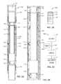
- FIG. 1illustrates a tubing string having indexing sleeves according to the present disclosure.
- FIGS. 2A-2Billustrate an indexing sleeve according to the present disclosure in a closed condition.
- FIG. 2Cdiagrams a controller for the indexing sleeve of FIG. 2A .
- FIG. 2Dshows a frac dart for use with the indexing sleeve of FIG. 2A .
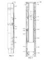
- FIGS. 3A-3Fshow the indexing sleeve in various stages of operation.
- FIGS. 4A-4Cschematically illustrate an arrangement of indexing sleeves in various stages of operation.
- FIG. 5Aillustrates another indexing sleeve according to the present disclosure in a closed condition.
- FIG. 5Bshows the indexing sleeve of FIG. 5A during opening.
- FIG. 5Cshows a frac dart for use with the sleeve of FIG. 5A .
- FIG. 6Aillustrates yet another indexing sleeve according to the present disclosure in a closed condition.
- FIGS. 6B-6Cshows lateral cross-sections of the indexing sleeve of FIG. 6A .
- FIG. 6Dshows the indexing sleeve of FIG. 6A during a stage of closing.
- FIG. 7illustrates yet another indexing sleeve according to the present disclosure in a closed condition.
- FIG. 8shows an isolation sleeve according in an opened condition.
- FIGS. 9A-9Bschematically illustrate an arrangement of sleeves in various stages of operation.
- a tubing string 12 for a wellbore fluid treatment system 20 shown in FIG. 1deploys in a wellbore 10 from a rig 30 having a pumping system 35 .
- the string 12has flow tools or indexing sleeves 100 A-C disposed along its length.
- Various packersisolate portions of the wellbore 10 into isolated zones.
- the wellbore 10can be an opened or cased hole, and the packers 40 can be any suitable type of packer intended to isolate portions of the wellbore into isolated zones.
- the indexing sleeves 100 A-Cdeploy on the tubing string 12 between the packers 40 and can be used to divert treatment fluid selectively to the isolated zones of the surrounding formation.
- the tubing string 12can be part of a frac assembly, for example, having a top liner packer (not shown), a wellbore isolation valve (not shown), and other packers and sleeves (not shown) in addition to those shown. If the wellbore has casing, then the wellbore 10 can have casing perforations 14 at various points.
- operatorsdeploy a setting ball to close the wellbore isolation valve (not shown). Then, operators rig up fracing surface equipment and pump fluid down the wellbore to open a pressure actuated sleeve (not shown) toward the end of the tubing string 12 . This treats a first zone of the formation. Then, in a later stage of the operation, operators selectively actuate the indexing sleeves 100 A-C between the packers 40 to treat the isolated zones depicted in FIG. 1 .
- the indexing sleeves 100 A-Chave activatable catches (not shown) according to the present disclosure. Based on a specific number of plugs (i.e., darts, balls or other the like) dropped down the tubing string 12 , internal components of a given indexing sleeve 100 A-C activate and engage the dropped plug. In this way, one sized plug can be dropped down the tubing string 12 to open the indexing sleeve 100 A-C selectively.
- plugsi.e., darts, balls or other the like
- indexing sleeves 100 A-CWith a general understanding of how the indexing sleeves 100 A-C are used, attention now turns to details of an indexing sleeve 100 shown in FIGS. 2A-2C and FIGS. 3A-3F .
- the indexing sleeve 100has a housing 110 defining a bore 102 therethrough and having ends 104 / 106 for coupling to a tubing string (not shown). Inside, the housing 110 has two inserts (i.e., insert 120 and sleeve 140 ) disposed in its bore 102 .
- the insert 120can move from a closed position ( FIG. 2A ) to an open position ( FIG. 3C ) when an appropriate plug (e.g., dart 150 of FIG. 2D or other form of plug) is passed through the indexing sleeve 100 as discussed in more detail below.
- the sleeve 140can move from a closed position ( FIG. 2A ) to an opened position ( FIG. 3D ) when another appropriate plug (e.g. dart 150 or other form of plug) is passed later through the indexing sleeve 100 as also discussed in more detail below.
- the indexing sleeve 100is run in the hole in a closed condition.
- the insert 120covers a portion of the sleeve 140 .
- the sleeve 140covers external ports 112 in the housing 110 , and peripheral seals 142 / 144 on the sleeve 140 prevent fluid communication between the bore 102 and these ports 112 .
- the insert 120has the open condition ( FIG. 3C )
- the insert 120is moved away from the sleeve 140 so that a profile 146 on the sleeve 140 is exposed in the housing's bore 102 .
- the sleeve 140 in the open position( FIG. 3D ) is moved away from the ports 112 so that fluid in the bore 102 can pass out through the ports 112 to the surrounding annulus and treat the adjacent formation.
- control circuitry 130 in the indexing sleeve 100is programmed to allow a set number of frac darts 150 to pass through the indexing sleeve 100 before activation. Then, the indexing sleeve 100 runs downhole in the closed condition as shown in FIGS. 2A and 3A . To then begin a frac operation, operators drop a frac dart 150 down the tubing string from the surface.
- the dart 150has an external seal 152 disposed thereabout for engaging in the sleeve ( 140 ).
- the dart 150also has retractable X-type keys 156 (or other type of dog or key) that can retract and extend from the dart 150 .
- the dart 150has a sensing element 154 .
- this sensing element 154is a magnetic strip or element disposed internally or externally on the dart 150 .
- the dart 150eventually reaches the indexing sleeve 100 as shown in FIG. 3B . Because the insert 120 covers the profile 146 in the sleeve 140 , the dropped dart 150 cannot land in the sleeve's profile 146 and instead continues through most of the indexing sleeve 100 . Eventually, the sensing element 154 of the dart 150 meets up with a sensor 134 disposed in the housing's bore 102 .
- this sensor 134communicates an electronic signal to control circuitry 130 in response to the passing sensing element 154 .
- the control circuitry 130can be on a circuit board housed in the indexing sleeve 100 or elsewhere.
- the signalindicates when the dart's sensing element 154 has met the sensor 134 .
- the sensor 134can be a hall effect sensor or any other sensor triggered by magnetic interaction.
- the sensor 134can be some other type of electronic device.
- the sensor 134could be some form of mechanical or electro-mechanical switch, although an electronic sensor is preferred.
- the control circuitry 130uses the sensor's signal to count, detects, or reads the passage of the sensing element 154 on the dart 150 , which continues down the tubing string (not shown). The process of dropping a dart 150 and counting its passage with the sensor 134 is then repeated for as many darts 150 the sleeve 100 is set to pass. Once the number of passing darts 150 is one less than the number set to open this indexing sleeve 100 , the control circuitry 130 activates a valve 136 on the sleeve 100 when this second to last dart 150 has passed and generated a sensor signal. Once activated, the valve 136 moves a plunger 138 that opens a port 118 . This communicates a first sealed chamber 116 a between the insert 120 and the housing 110 with the surrounding annulus, which is at higher pressure.
- FIG. 2Cshows an example of a controller 160 for the disclosed indexing sleeve 100 .
- a hall effect sensor 162responds to the magnetic strip ( 152 ) of the dart ( 150 ), and a counter 164 counts the passage of the dart's strip ( 152 ).
- the counter 164activates a switch 165 , and a power source 166 activates a solenoid valve 168 , which moves a plunger ( 138 ) to open the port ( 118 ).
- a solenoid valve 168can be used, any other mechanism or device capable of maintaining a port closed with a closure until activated can be used. Such a device can be electronically or mechanically activated.
- a spring-biased plungercould be used to close off the port.
- a filament or other breakable componentcan hold this biased plunger in a closed state to close off the port.
- an electric current, heat, force or the likecan break the filament or other component, allowing the plunger to open communication through the port.
- the insert 120shears free of shear pins 121 to the housing 110 . Now freed, the insert 120 moves (downward) in the housing's bore 102 by the piston effect of the filling chamber 116 a . Once the insert 120 has completed its travel, its distal end exposes the profile 146 inside the sleeve 140 as also shown in FIG. 3C .
- this dart 150reaches the exposed profile 146 on the sleeve 140 .
- the biased keys 156 on the dart 150extend outward and engage or catch the profile 146 .
- the key 156has a notch locking in the profile 146 in only a first direction tending to open the second insert. The rest of the key 156 , however, allows the dart 150 move in a second direction opposite to the first direction so it can be produced to the surface as discussed later.
- the dart's seal 152seals inside an interior passage or seat in the sleeve 140 . Because the dart 150 is passing through the sleeve 140 , interaction of the seal 152 with the surrounding sleeve 140 can tend to slow the dart's passage. This helps the keys 156 to catch in the exposed profile 146 .
- the wellcan be produced through the open sleeve 100 without restriction or intervention.
- the indexing sleevecan be manually reset closed by using an appropriate tool.
- FIGS. 4A-4Cshow an arrangement of indexing sleeves 100 B-F in various stages of operation.
- a first dart 150 Ahas been dropped down the tubing string 12 , and it has passed through each of the indexing sleeves 100 B-F, increasing their counts.
- the lowermost indexing sleeve 100 Bbeing set to one count activates so that its insert 120 moves by fluid pressure entering from side port 118 .
- next dart 150 BWhen the next dart 150 B is dropped as shown in FIG. 4B , it passes through each sleeve 100 C-F and engages in the exposed profile 146 of the lowermost sleeve 100 B. After the dart 150 passes the second-to-last indexing sleeve 100 C, its insert 120 activates and moves to expose its sleeve 140 's profile. Eventually, the dart 150 B seats in the lowermost sleeve 100 B. Frac fluid pumped down the tubing string 12 can then exit the sleeve 100 B and stimulate the surrounding interval.
- each dart 150 Cdrops down the tubing sting and adds to the count of each sleeve 100 D-F.
- this dart 150 Cactivates the third sleeve 100 D when passing as shown in FIG. 4B .
- this dart 150 Clands in the second sleeve 100 C as shown in FIG. 4C so that fracing can be performed and the next dart 150 D dropped. This operation continues up the tubing string 12 .
- Each deployed dart 150can have the same diameter, and each indexing sleeve 100 can be set to ever-increasing counts of passing darts 150 .
- the previous indexing sleeve 100 of FIG. 2Auses a profile 146 on its sleeve 140 , while the dart 150 of FIG. 2D uses biased keys 156 to catch on the profile 146 when exposed.
- a reverse arrangementcan be used.
- an indexing sleeve 100has many of the same components as the previous embodiment so that like reference numerals are used.
- the sleeve 140has a plurality of keys or dogs 148 disposed in surrounding slots in the sleeve 140 . Springs or other biasing members 149 bias these dogs 148 through these slots toward the interior of the sleeve 140 where a frac plug passes.
- these keys 148remain retracted in the sleeve 140 so that frac darts 150 can pass as desired.
- the insert 120has been activated by one of the darts 150 and has moved (downward) in the sleeve 100 , the insert's proximal end 125 disengages from the keys 148 . This allows the springs 149 to bias the keys 148 outward into the bore 102 of the sleeve 100 . At this point, the next dart 150 will engage the keys 148 .
- FIG. 5Cshows a dart 150 having a magnetic strip 154 , seal 152 , and profile 158 .
- the dart 150meets up to the sleeve 140 , and the extended keys 148 catch in the dart's exposed profile 158 .
- fluid pressure applied against the caught dart 150can move the sleeve 140 (downward) in the indexing sleeve 100 to open the housing's ports 112 .
- indexing sleeves 100 and darts 150have keys and profiles.
- an indexing sleeve 100 shown in FIG. 6Auses a ball 170 having a sensing element 172 , such as a magnet. Again, this indexing sleeve 100 has many of the same components as the previous embodiment so that like reference numerals are used.
- the sleeve 140has a plurality of keys or dogs 148 disposed in surrounding slots in the sleeve 140 . Springs or other biasing members 149 bias these dogs 148 through these slots toward the interior of the sleeve 140 .
- the keys 148remain retracted as shown in FIG. 6A .
- the insert's distal end 127disengages from the keys 148 .
- the distal end 127 shown in FIG. 6Dinitially covers the keys 148 and exposes them once the insert 120 moves.
- the springs 149bias the keys 148 outward into the bore 102 .
- the next ball 170 ′will engage the extended keys 148 .
- the end-section in FIG. 6Bshows how the distal end 127 of the insert 120 can hold the keys 148 retracted in the sleeve 140 , allowing for passage of balls 170 through the larger diameter D.
- the end-section in FIG. 6Cshows how the extend keys 148 create a seat with a restricted diameter d to catch a ball 170 .
- the keys 148can be used, although any suitable number could be used.
- the proximate ends of the keys 148can have shoulders to catch inside the sleeve's slots to prevent the keys 148 from passing out of these slots.
- the keys 148 when extendedcan be configured to have 1 ⁇ 8-inch interference fit to engage a corresponding plug (e.g., ball 170 ).
- the tolerancecan depend on a number of factors.
- Previous indexing sleeves 100included an insert moved by fluid pressure once a set number of dart or balls have passed through the sleeve 100 .
- the moved insert 120then reveals a profile or keys on a sleeve 140 that can catch the next plug (e.g., dart 150 or ball 170 ) dropped through the indexing sleeve 100 .
- an indexing sleeve 100 shown in FIG. 7lacks the separate insert and sliding sleeve from before. Instead, this sleeve has an integral insert 180 . Many of the sleeve's components are the same as before, including the control circuitry 130 , battery 132 , sensor 134 , valve 136 , etc.
- the insert 180defines the chambers 116 a - b with the housing 110 and covers the housing's ports 112 .
- this sleeve 100opens when a set number of plugs has passed, but the sleeve 100 lacks a seat or the like to catch a dart or ball dropped therein. Accordingly, this sleeve 100 may be useful when two or more sleeves along the tubing string are to be opened by the same passing dart or ball. This may be useful when a long expanse of a formation along a wellbore is to be treated.
- indexing sleeves 100can be used on a tubing string. These indexing sleeves 100 can be used in conjunction with one or more sliding sleeves 50 .
- a sliding sleeve 50is shown in an opened condition.
- the sliding sleeve 50defines a bore 52 therethrough, and an insert 54 can be moved from a closed condition to an open condition (as shown).
- a dropped plug 190e.g., dart, ball, or the like
- a dropped plug 190with its specific diameter is intended to land on an appropriately sized ball seat 58 within the insert 54 .
- the plug 190typically seals in the seat 56 and does not allow fluid pressure to pass further downhole from the sleeve 50 .
- the fluid pressure communicated down the isolation sleeve 50therefore forces against the seated plug 190 and moves the insert 54 open.
- openings in the insert 54 in the open conditioncommunicate with external ports 56 in the isolation sleeve 50 to allow fluid in the sleeve's bore 52 to pass out to the surrounding annulus.
- Seals 57such as chevron seals, on the inside of the bore 52 can be used to seal the external ports 56 and the insert 54 .
- One suitable example for the isolation sleeve 50is the Single-Shot ZoneSelect Sleeve available from Weatherford.
- FIGS. 9A-9Bshow an exemplary arrangement of multiple indexing sleeves 200 and sliding sleeves 50 .
- the arrangement of sleevesinclude a sliding sleeve 50 (S A ), a succession of three indexing sleeves 200 (I 1 -I 3 ), and another sliding sleeve 50 (S B ).
- These sleeves 50 / 200can be divided into any number of zones using packers (not shown), and their arrangement as depicted in FIG. 9A is illustrative. Depending on the particular implementation and the treatment desired, any number of sleeves 50 / 200 can be arranged in any number of zones, and packers or other devices (not shown) can be used to isolate various intervals between any of the sleeves 50 / 200 from one another.
- Dropping of two different sized plugs(A & B) (i.e., dart, balls, or the like) with different sizes are illustrated in different stages for this example. Any number of differently sized plugs, balls, darts, or the like can be used.
- the relevant size of the plugs(A & B) pertains to their diameters, which can range from 1-inch to 33 ⁇ 4-inch in some instances.
- plug (A)In the first stage, operators drop the smaller plug (A). As it travels, plug (A) passes through sliding sleeve 50 (SB) without engaging its larger seat. The plug (A) also passes through indexing sleeves 100 (I 1 -I 3 ) without opening them. Finally, the plug (A) engages the seat in sliding sleeve 50 (S A ). Fluid treatment down the tubing string 12 opens the sliding sleeve 50 (S A ) and stimulates the formation adjacent to it.
- the plug (A)triggers their activation. Rather than counting the number of passing plugs, however, these sleeves 200 use their sensors (e.g., 134 ) or other mechanism to trigger a timed activation of the sleeves 200 . In this case, the controller of the sleeve 200 uses a timer instead of (or in addition to) the counter described previously in FIG. 2D . Each of the indexing sleeves 200 can then be set to activate at successive times.
- indexing sleeves 200(I 1 -I 3 ) activate at different or same times based on the preset time interval they are set to after passage of the initial sized plug (A). Additionally, depending on the type of disclosed sleeve used, additional plugs (A) of the same size may or may not be dropped to open these sleeves 200 .
- any of the sleeves 200can be similar to the sleeve 100 of FIG. 7 so that they open once activated but do not have a seat for engaging a dropped plug (A).
- such sleevescould expose more of a formation in the same or different interval for treatment at the same or successive times as the lowermost sliding sleeve 50 (S A ).
- operatorscan drop a larger sized plug (B) to land in the other sliding sleeve 50 (S B ) to seal off all of the sleeves 50 (S A ) and 200 (I 1 -I 3 ).
- one or more of the sleeves 200can be similar to the sleeves 100 of FIG. 2A , 5 A, or 6 A.
- the timer of the control circuitry ( 130 )can activate the valve ( 136 ) to fill the piston chamber ( 116 a ) and move the sleeve's insert ( 120 ). This can reveal the profile ( 146 ) of the sliding sleeve ( 140 ) or can free keys ( 148 ) of the sliding sleeve 140 to engage another plug (A) dropped down the tubing string 12 .
- the indexing sleeve 200 (I 1 )can be such a sleeve and can activate at a set time T 1 (e.g., a couple of hours or so) after the first dropped plug (A) has passed and landed in the lowermost sliding sleeve 50 (S A ).
- the set time T 1gives operators time to treat the interval near the sliding sleeve 50 (S A ).
- the sleeve 200 (I 1 )activates after time T 1 , however, operators drop a same sized plug (A) to catch in this indexing sleeve 200 (I 1 ) so its adjacent formation can be treated.
- Indexing sleeve 200 (I 2 )can activate at a later time T 2 after the second plug (A) has passed and can catch a third plug (A), and the other sleeve 200 (I 3 ) can then do the same with another time T 3 . In this way, operators can treat any number of intervals using the same sized plug (A) before using another sized plug (B) to land in the other sliding sleeve 50 (S B ) in a third stage.
- the plug (A)can be a ball or dart with a magnetic element or strip to be detected by the sleeves 200 . Due to the narrowness of the tubing strings bore and the size limitations for plugs, conventional approaches allow operators to treat only a limited number of intervals using an array of ever-increasing sized plugs and sleeve seats. The number of sizes may be limited to about 20. Being able to insert one or more of the indexing sleeves 200 between conventionally seating sliding sleeves 50 , however, operators can greatly expand the number of intervals that they can treat with the limited number of sized plugs and sleeve seats.
- a plugcan be a dart, a ball, or any other comparable item for dropping down a tubing string and landing in a sliding sleeve. Accordingly, plug, dart, ball, or other such term can be used interchangeably herein when referring to such items.
- the various indexing sleeves disclosed hereincan be arranged with one another and with other sliding sleeves. It is possible, therefore, one type of indexing sleeve and plug to be incorporated into a tubing string having another type of indexing sleeve and plug disclosed herein.
Landscapes
- Life Sciences & Earth Sciences (AREA)
- Engineering & Computer Science (AREA)
- Geology (AREA)
- Mining & Mineral Resources (AREA)
- Physics & Mathematics (AREA)
- Environmental & Geological Engineering (AREA)
- Fluid Mechanics (AREA)
- General Life Sciences & Earth Sciences (AREA)
- Geochemistry & Mineralogy (AREA)
- Quick-Acting Or Multi-Walled Pipe Joints (AREA)
- A Measuring Device Byusing Mechanical Method (AREA)
Abstract
Description
Claims (52)
Priority Applications (7)
| Application Number | Priority Date | Filing Date | Title |
|---|---|---|---|
| US12/753,331US8505639B2 (en) | 2010-04-02 | 2010-04-02 | Indexing sleeve for single-trip, multi-stage fracing |
| US13/022,504US8403068B2 (en) | 2010-04-02 | 2011-02-07 | Indexing sleeve for single-trip, multi-stage fracing |
| CA2857825ACA2857825C (en) | 2010-04-02 | 2011-03-28 | Indexing sleeve for single-trip, multi-stage fracing |
| CA2735402ACA2735402C (en) | 2010-04-02 | 2011-03-28 | Indexing sleeve for single-trip, multi-stage fracing |
| EP20110160133EP2372080B1 (en) | 2010-04-02 | 2011-03-29 | Indexing Sleeve for Single-Trip, Multi-Stage Fracturing |
| AU2011201418AAU2011201418B2 (en) | 2010-04-02 | 2011-03-29 | Indexing sleeve for single-trip, multi-stage fracing |
| US13/848,376US9441457B2 (en) | 2010-04-02 | 2013-03-21 | Indexing sleeve for single-trip, multi-stage fracing |
Applications Claiming Priority (1)
| Application Number | Priority Date | Filing Date | Title |
|---|---|---|---|
| US12/753,331US8505639B2 (en) | 2010-04-02 | 2010-04-02 | Indexing sleeve for single-trip, multi-stage fracing |
Related Child Applications (1)
| Application Number | Title | Priority Date | Filing Date |
|---|---|---|---|
| US13/022,504Continuation-In-PartUS8403068B2 (en) | 2010-04-02 | 2011-02-07 | Indexing sleeve for single-trip, multi-stage fracing |
Publications (2)
| Publication Number | Publication Date |
|---|---|
| US20110240311A1 US20110240311A1 (en) | 2011-10-06 |
| US8505639B2true US8505639B2 (en) | 2013-08-13 |
Family
ID=44260196
Family Applications (1)
| Application Number | Title | Priority Date | Filing Date |
|---|---|---|---|
| US12/753,331Expired - Fee RelatedUS8505639B2 (en) | 2010-04-02 | 2010-04-02 | Indexing sleeve for single-trip, multi-stage fracing |
Country Status (4)
| Country | Link |
|---|---|
| US (1) | US8505639B2 (en) |
| EP (1) | EP2372080B1 (en) |
| AU (1) | AU2011201418B2 (en) |
| CA (2) | CA2857825C (en) |
Cited By (27)
| Publication number | Priority date | Publication date | Assignee | Title |
|---|---|---|---|---|
| US8695710B2 (en) | 2011-02-10 | 2014-04-15 | Halliburton Energy Services, Inc. | Method for individually servicing a plurality of zones of a subterranean formation |
| US8839871B2 (en) | 2010-01-15 | 2014-09-23 | Halliburton Energy Services, Inc. | Well tools operable via thermal expansion resulting from reactive materials |
| US8893811B2 (en) | 2011-06-08 | 2014-11-25 | Halliburton Energy Services, Inc. | Responsively activated wellbore stimulation assemblies and methods of using the same |
| US8899334B2 (en) | 2011-08-23 | 2014-12-02 | Halliburton Energy Services, Inc. | System and method for servicing a wellbore |
| US8973657B2 (en) | 2010-12-07 | 2015-03-10 | Halliburton Energy Services, Inc. | Gas generator for pressurizing downhole samples |
| US8991509B2 (en) | 2012-04-30 | 2015-03-31 | Halliburton Energy Services, Inc. | Delayed activation activatable stimulation assembly |
| US20150122493A1 (en)* | 2013-11-07 | 2015-05-07 | Baker Hughes Incorporated | Frac sleeve system and method for non-sequential downhole operations |
| WO2015084322A1 (en)* | 2013-12-03 | 2015-06-11 | Halliburton Energy Services, Inc. | Locking mechanism for downhole positioning of sleeves |
| US9169705B2 (en) | 2012-10-25 | 2015-10-27 | Halliburton Energy Services, Inc. | Pressure relief-assisted packer |
| US9187978B2 (en) | 2013-03-11 | 2015-11-17 | Weatherford Technology Holdings, Llc | Expandable ball seat for hydraulically actuating tools |
| US20160032670A1 (en)* | 2013-03-15 | 2016-02-04 | Petrowell Limited | Shifting Tool |
| US9284817B2 (en) | 2013-03-14 | 2016-03-15 | Halliburton Energy Services, Inc. | Dual magnetic sensor actuation assembly |
| US9366134B2 (en) | 2013-03-12 | 2016-06-14 | Halliburton Energy Services, Inc. | Wellbore servicing tools, systems and methods utilizing near-field communication |
| US9428976B2 (en) | 2011-02-10 | 2016-08-30 | Halliburton Energy Services, Inc. | System and method for servicing a wellbore |
| US20160258259A1 (en)* | 2014-08-07 | 2016-09-08 | Halliburton Energy Services, Inc. | Multi-zone actuation system using wellbore projectiles and flapper valves |
| US9587486B2 (en) | 2013-02-28 | 2017-03-07 | Halliburton Energy Services, Inc. | Method and apparatus for magnetic pulse signature actuation |
| US9752409B2 (en)* | 2016-01-21 | 2017-09-05 | Completions Research Ag | Multistage fracturing system with electronic counting system |
| US9752414B2 (en) | 2013-05-31 | 2017-09-05 | Halliburton Energy Services, Inc. | Wellbore servicing tools, systems and methods utilizing downhole wireless switches |
| US9784070B2 (en) | 2012-06-29 | 2017-10-10 | Halliburton Energy Services, Inc. | System and method for servicing a wellbore |
| US10125573B2 (en)* | 2015-10-05 | 2018-11-13 | Baker Hughes, A Ge Company, Llc | Zone selection with smart object selectively operating predetermined fracturing access valves |
| US10408018B2 (en) | 2014-08-07 | 2019-09-10 | Packers Plus Energy Services Inc. | Actuation dart for wellbore operations, wellbore treatment apparatus and method |
| US10591068B2 (en) | 2015-05-14 | 2020-03-17 | Halliburton Energy Services, Inc. | Ball and seat valve for high temperature and pressure applications |
| US10808523B2 (en) | 2014-11-25 | 2020-10-20 | Halliburton Energy Services, Inc. | Wireless activation of wellbore tools |
| US10900323B2 (en) | 2017-11-06 | 2021-01-26 | Entech Solutions AS | Method and stimulation sleeve for well completion in a subterranean wellbore |
| US10907471B2 (en) | 2013-05-31 | 2021-02-02 | Halliburton Energy Services, Inc. | Wireless activation of wellbore tools |
| US11746613B2 (en) | 2020-01-30 | 2023-09-05 | Advanced Upstream Ltd. | Devices, systems, and methods for selectively engaging downhole tool for wellbore operations |
| US12006793B2 (en) | 2020-01-30 | 2024-06-11 | Advanced Upstream Ltd. | Devices, systems, and methods for selectively engaging downhole tool for wellbore operations |
Families Citing this family (68)
| Publication number | Priority date | Publication date | Assignee | Title |
|---|---|---|---|---|
| CN102052068B (en) | 2009-11-11 | 2013-04-24 | 西安通源石油科技股份有限公司 | Method and device for composite fracturing/perforating for oil/gas well |
| US9027667B2 (en) | 2009-11-11 | 2015-05-12 | Tong Oil Tools Co. Ltd. | Structure for gunpowder charge in combined fracturing perforation device |
| GB2478995A (en) | 2010-03-26 | 2011-09-28 | Colin Smith | Sequential tool activation |
| GB2478998B (en) | 2010-03-26 | 2015-11-18 | Petrowell Ltd | Mechanical counter |
| WO2011134069A1 (en)* | 2010-04-28 | 2011-11-03 | Sure Tech Tool Services Inc. | Apparatus and method for fracturing a well |
| US9739117B2 (en) | 2010-04-28 | 2017-08-22 | Gryphon Oilfield Solutions, Llc | Profile selective system for downhole tools |
| CA2813645C (en)* | 2010-10-06 | 2019-10-29 | Packers Plus Energy Services Inc. | Actuation dart for wellbore operations, wellbore treatment apparatus and method |
| US20120261131A1 (en)* | 2011-04-14 | 2012-10-18 | Peak Completion Technologies, Inc. | Assembly for Actuating a Downhole Tool |
| CN102094613A (en) | 2010-12-29 | 2011-06-15 | 西安通源石油科技股份有限公司 | Composite perforating method and device carrying support agent |
| US9909384B2 (en)* | 2011-03-02 | 2018-03-06 | Team Oil Tools, Lp | Multi-actuating plugging device |
| US8757274B2 (en) | 2011-07-01 | 2014-06-24 | Halliburton Energy Services, Inc. | Well tool actuator and isolation valve for use in drilling operations |
| US20130048290A1 (en)* | 2011-08-29 | 2013-02-28 | Halliburton Energy Services, Inc. | Injection of fluid into selected ones of multiple zones with well tools selectively responsive to magnetic patterns |
| US9151138B2 (en)* | 2011-08-29 | 2015-10-06 | Halliburton Energy Services, Inc. | Injection of fluid into selected ones of multiple zones with well tools selectively responsive to magnetic patterns |
| US9238953B2 (en)* | 2011-11-08 | 2016-01-19 | Schlumberger Technology Corporation | Completion method for stimulation of multiple intervals |
| US9394752B2 (en)* | 2011-11-08 | 2016-07-19 | Schlumberger Technology Corporation | Completion method for stimulation of multiple intervals |
| US9297242B2 (en) | 2011-12-15 | 2016-03-29 | Tong Oil Tools Co., Ltd. | Structure for gunpowder charge in multi-frac composite perforating device |
| CN102410006B (en) | 2011-12-15 | 2014-05-07 | 西安通源石油科技股份有限公司 | Explosive loading structure for multi-stage composite perforating device |
| US8919434B2 (en)* | 2012-03-20 | 2014-12-30 | Kristian Brekke | System and method for fracturing of oil and gas wells |
| US9506324B2 (en) | 2012-04-05 | 2016-11-29 | Halliburton Energy Services, Inc. | Well tools selectively responsive to magnetic patterns |
| WO2013170372A1 (en)* | 2012-05-18 | 2013-11-21 | Packers Plus Energy Services Inc. | Apparatus and method for downhole activation |
| GB2502301A (en) | 2012-05-22 | 2013-11-27 | Churchill Drilling Tools Ltd | Downhole tool activation apparatus |
| US9650851B2 (en)* | 2012-06-18 | 2017-05-16 | Schlumberger Technology Corporation | Autonomous untethered well object |
| AU2013298345B2 (en)* | 2012-07-31 | 2016-12-15 | Weatherford Technology Holdings, Llc | Downhole apparatus and method |
| US9410399B2 (en) | 2012-07-31 | 2016-08-09 | Weatherford Technology Holdings, Llc | Multi-zone cemented fracturing system |
| US8919440B2 (en)* | 2012-09-24 | 2014-12-30 | Kristian Brekke | System and method for detecting screen-out using a fracturing valve for mitigation |
| WO2014074093A1 (en) | 2012-11-07 | 2014-05-15 | Halliburton Energy Services, Inc. | Time delay well flow control |
| CN103899288B (en)* | 2012-12-25 | 2016-07-06 | 中国石油化工股份有限公司 | Fracturing sliding bush assembly |
| US9410401B2 (en)* | 2013-03-13 | 2016-08-09 | Completion Innovations, LLC | Method and apparatus for actuation of downhole sleeves and other devices |
| US9976388B2 (en)* | 2013-03-13 | 2018-05-22 | Completion Innovations, LLC | Method and apparatus for actuation of downhole sleeves and other devices |
| US10316645B2 (en) | 2013-05-16 | 2019-06-11 | Schlumberger Technology Corporation | Autonomous untethered well object |
| US9512695B2 (en)* | 2013-06-28 | 2016-12-06 | Schlumberger Technology Corporation | Multi-stage well system and technique |
| US20150021021A1 (en)* | 2013-07-17 | 2015-01-22 | Halliburton Energy Services, Inc. | Multiple-Interval Wellbore Stimulation System and Method |
| US9482072B2 (en) | 2013-07-23 | 2016-11-01 | Halliburton Energy Services, Inc. | Selective electrical activation of downhole tools |
| US9739120B2 (en) | 2013-07-23 | 2017-08-22 | Halliburton Energy Services, Inc. | Electrical power storage for downhole tools |
| US9822610B2 (en)* | 2013-07-31 | 2017-11-21 | Halliburton Energy Services, Inc. | Selective magnetic positioning tool |
| US9587477B2 (en) | 2013-09-03 | 2017-03-07 | Schlumberger Technology Corporation | Well treatment with untethered and/or autonomous device |
| US9631468B2 (en) | 2013-09-03 | 2017-04-25 | Schlumberger Technology Corporation | Well treatment |
| CA2924452C (en) | 2013-09-18 | 2019-10-29 | Packers Plus Energy Services Inc. | Hydraulically actuated tool with pressure isolator |
| US9765605B2 (en)* | 2013-10-25 | 2017-09-19 | Weatherford Technology Holdings, Llc | Re-fracture apparatus and method for wellbore |
| US9534484B2 (en)* | 2013-11-14 | 2017-01-03 | Baker Hughes Incorporated | Fracturing sequential operation method using signal responsive ported subs and packers |
| US9523258B2 (en) | 2013-11-18 | 2016-12-20 | Weatherford Technology Holdings, Llc | Telemetry operated cementing plug release system |
| US9528346B2 (en) | 2013-11-18 | 2016-12-27 | Weatherford Technology Holdings, Llc | Telemetry operated ball release system |
| US9777569B2 (en) | 2013-11-18 | 2017-10-03 | Weatherford Technology Holdings, Llc | Running tool |
| CN103711456A (en)* | 2013-12-16 | 2014-04-09 | 东营市福利德石油科技开发有限责任公司 | Hydraulic switching tool for deep-water oil well |
| US10221648B2 (en)* | 2014-01-24 | 2019-03-05 | Completions Research Ag | Multistage high pressure fracturing system with counting system |
| US9920620B2 (en) | 2014-03-24 | 2018-03-20 | Halliburton Energy Services, Inc. | Well tools having magnetic shielding for magnetic sensor |
| RU2550633C1 (en)* | 2014-04-15 | 2015-05-10 | Открытое акционерное общество "Татнефть" имени В.Д. Шашина | Aggregate for dual bed operation in well |
| EP2982828A1 (en)* | 2014-08-08 | 2016-02-10 | Welltec A/S | Downhole valve system |
| EP3018285B1 (en)* | 2014-11-07 | 2018-12-26 | Weatherford Technology Holdings, LLC | Indexing stimulating sleeve and other downhole tools |
| CA2976368C (en) | 2015-02-13 | 2019-09-24 | Weatherford Technology Holdings, Llc | Pressure insensitive counting toe sleeve |
| CA2970825A1 (en)* | 2015-02-19 | 2016-08-25 | Halliburton Energy Services, Inc. | Activation device and activation of multiple downhole tools with a single activation device |
| US10161220B2 (en) | 2015-04-24 | 2018-12-25 | Ncs Multistage Inc. | Plug-actuated flow control member |
| EP3567210A1 (en) | 2015-05-04 | 2019-11-13 | Weatherford Technology Holdings, LLC | Dual sleeve stimulation tool |
| CA2941571A1 (en) | 2015-12-21 | 2017-06-21 | Packers Plus Energy Services Inc. | Indexing dart system and method for wellbore fluid treatment |
| CA3017937A1 (en)* | 2016-03-18 | 2017-09-21 | Completion Innovations, LLC | Method and apparatus for actuation of downhole sleeves and other devices |
| US10364650B2 (en) | 2017-02-14 | 2019-07-30 | 2054351 Alberta Ltd | Multi-stage hydraulic fracturing tool and system |
| US10364648B2 (en) | 2017-02-14 | 2019-07-30 | 2054351 Alberta Ltd | Multi-stage hydraulic fracturing tool and system |
| CA3056524A1 (en) | 2018-09-24 | 2020-03-24 | Resource Well Completion Technologies Inc. | Systems and methods for multi-stage well stimulation |
| US11041366B2 (en)* | 2019-11-07 | 2021-06-22 | Fmc Technologies, Inc. | Diverter valve |
| CN114059964B (en)* | 2020-07-31 | 2024-05-28 | 中国石油化工股份有限公司 | Hydraulic closing tool for closing sliding sleeve switch and sliding sleeve switch tool assembly |
| WO2022040414A1 (en)* | 2020-08-20 | 2022-02-24 | Schlumberger Technology Corporation | Remote pressure sensing port for a downhole valve |
| CN112049605B (en)* | 2020-09-26 | 2022-11-01 | 东北石油大学 | An underground full-bore infinite-stage ball-counting fracturing sliding sleeve |
| CN116171345A (en) | 2020-10-09 | 2023-05-26 | 井博士股份有限公司 | Systems and methods for multistage fracturing |
| US11879326B2 (en) | 2020-12-16 | 2024-01-23 | Halliburton Energy Services, Inc. | Magnetic permeability sensor for using a single sensor to detect magnetic permeable objects and their direction |
| CN113404477A (en)* | 2021-08-05 | 2021-09-17 | 三一石油智能装备有限公司 | Fracturing tool |
| CN115075793B (en)* | 2022-07-01 | 2023-07-25 | 西南石油大学 | Infinite intelligent sliding sleeve |
| US12352147B2 (en) | 2022-10-25 | 2025-07-08 | The Wellboss Company, Inc. | Systems and methods for multistage fracturing |
| WO2025134083A1 (en)* | 2023-12-22 | 2025-06-26 | Kobold Corporation | Sleeve and dart assemblies and related completion systems and methods for hydraulic fracturing operations |
Citations (56)
| Publication number | Priority date | Publication date | Assignee | Title |
|---|---|---|---|---|
| US3054415A (en) | 1959-08-03 | 1962-09-18 | Baker Oil Tools Inc | Sleeve valve apparatus |
| US4099563A (en) | 1977-03-31 | 1978-07-11 | Chevron Research Company | Steam injection system for use in a well |
| US4520870A (en) | 1983-12-27 | 1985-06-04 | Camco, Incorporated | Well flow control device |
| US4574894A (en) | 1985-07-12 | 1986-03-11 | Smith International, Inc. | Ball actuable circulating dump valve |
| US4823882A (en) | 1988-06-08 | 1989-04-25 | Tam International, Inc. | Multiple-set packer and method |
| US4893678A (en) | 1988-06-08 | 1990-01-16 | Tam International | Multiple-set downhole tool and method |
| US4907649A (en) | 1987-05-15 | 1990-03-13 | Bode Robert E | Restriction subs for setting cement plugs in wells |
| US4967841A (en) | 1989-02-09 | 1990-11-06 | Baker Hughes Incorporated | Horizontal well circulation tool |
| US5082062A (en) | 1990-09-21 | 1992-01-21 | Ctc Corporation | Horizontal inflatable tool |
| US5146992A (en) | 1991-08-08 | 1992-09-15 | Baker Hughes Incorporated | Pump-through pressure seat for use in a wellbore |
| US5244044A (en) | 1992-06-08 | 1993-09-14 | Otis Engineering Corporation | Catcher sub |
| EP0618347A2 (en) | 1993-03-31 | 1994-10-05 | Halliburton Company | Cement placement in well |
| US5499687A (en) | 1987-05-27 | 1996-03-19 | Lee; Paul B. | Downhole valve for oil/gas well |
| US6041857A (en) | 1997-02-14 | 2000-03-28 | Baker Hughes Incorporated | Motor drive actuator for downhole flow control devices |
| US6155350A (en) | 1999-05-03 | 2000-12-05 | Baker Hughes Incorporated | Ball seat with controlled releasing pressure and method setting a downhole tool ball seat with controlled releasing pressure and method setting a downholed tool |
| US6172614B1 (en) | 1998-07-13 | 2001-01-09 | Halliburton Energy Services, Inc. | Method and apparatus for remote actuation of a downhole device using a resonant chamber |
| US6253861B1 (en) | 1998-02-25 | 2001-07-03 | Specialised Petroleum Services Limited | Circulation tool |
| US20010013410A1 (en)* | 1999-09-07 | 2001-08-16 | Halliburton Energy Services, Inc. | Methods and associated apparatus for downhole data retrieval, monitoring and tool actuation |
| US6349766B1 (en) | 1998-05-05 | 2002-02-26 | Baker Hughes Incorporated | Chemical actuation of downhole tools |
| WO2002068793A1 (en) | 2001-02-22 | 2002-09-06 | Paul Bernard Lee | Ball activated tool for use in downhole drilling |
| US6464008B1 (en) | 2001-04-25 | 2002-10-15 | Baker Hughes Incorporated | Well completion method and apparatus |
| US6491097B1 (en) | 2000-12-14 | 2002-12-10 | Halliburton Energy Services, Inc. | Abrasive slurry delivery apparatus and methods of using same |
| US20030052670A1 (en) | 2001-09-17 | 2003-03-20 | Antech Limited | Non-invasive detectors for wells |
| US20030075326A1 (en) | 2001-10-22 | 2003-04-24 | Ebinger Charles D. | Well completion method |
| US20030145986A1 (en)* | 2002-02-01 | 2003-08-07 | Scientific Microsystems, Inc. | Differential pressure controller |
| US6634428B2 (en) | 2001-05-03 | 2003-10-21 | Baker Hughes Incorporated | Delayed opening ball seat |
| WO2004009955A1 (en) | 2002-07-24 | 2004-01-29 | Richard Selinger | Method and apparatus for causing pressure variations in a wellbore |
| GB2402954A (en) | 2003-06-18 | 2004-12-22 | Weatherford Lamb | Tool actuator with automatic control |
| US6907936B2 (en) | 2001-11-19 | 2005-06-21 | Packers Plus Energy Services Inc. | Method and apparatus for wellbore fluid treatment |
| US6920930B2 (en) | 2002-12-10 | 2005-07-26 | Allamon Interests | Drop ball catcher apparatus |
| US20060124310A1 (en) | 2004-12-14 | 2006-06-15 | Schlumberger Technology Corporation | System for Completing Multiple Well Intervals |
| US20060207764A1 (en) | 2004-12-14 | 2006-09-21 | Schlumberger Technology Corporation | Testing, treating, or producing a multi-zone well |
| RU58601U1 (en) | 2006-06-22 | 2006-11-27 | Открытое акционерное общество "Татнефть" им. В.Д. Шашина | Casing Cementing Device |
| US20070204995A1 (en) | 2006-01-25 | 2007-09-06 | Summit Downhole Dynamics, Ltd. | Remotely operated selective fracing system |
| US20070272413A1 (en) | 2004-12-14 | 2007-11-29 | Schlumberger Technology Corporation | Technique and apparatus for completing multiple zones |
| US20070285275A1 (en) | 2004-11-12 | 2007-12-13 | Petrowell Limited | Remote Actuation of a Downhole Tool |
| US20080053658A1 (en) | 2006-08-31 | 2008-03-06 | Wesson David S | Method and apparatus for selective down hole fluid communication |
| US7347289B2 (en) | 2002-09-03 | 2008-03-25 | Paul Bernard Lee | Dart-operated big bore by-pass valve |
| WO2008099166A2 (en) | 2007-02-16 | 2008-08-21 | Specialised Petroleum Services Group Limited | Valve seat assembly, downhole tool and methods |
| US20090044949A1 (en) | 2007-08-13 | 2009-02-19 | King James G | Deformable ball seat |
| US20090056934A1 (en) | 2007-08-27 | 2009-03-05 | Baker Hughes Incorporated | Interventionless multi-position frac tool |
| US20090084553A1 (en) | 2004-12-14 | 2009-04-02 | Schlumberger Technology Corporation | Sliding sleeve valve assembly with sand screen |
| US7581596B2 (en) | 2006-03-24 | 2009-09-01 | Dril-Quip, Inc. | Downhole tool with C-ring closure seat and method |
| US20090223663A1 (en) | 2008-03-07 | 2009-09-10 | Marathon Oil Company | Systems, assemblies and processes for controlling tools in a well bore |
| US20090223670A1 (en) | 2008-03-07 | 2009-09-10 | Marathon Oil Company | Systems, assemblies and processes for controlling tools in a well bore |
| US20090308588A1 (en)* | 2008-06-16 | 2009-12-17 | Halliburton Energy Services, Inc. | Method and Apparatus for Exposing a Servicing Apparatus to Multiple Formation Zones |
| US7661478B2 (en) | 2006-10-19 | 2010-02-16 | Baker Hughes Incorporated | Ball drop circulation valve |
| US20100155055A1 (en) | 2008-12-16 | 2010-06-24 | Robert Henry Ash | Drop balls |
| US20100282338A1 (en) | 2009-05-07 | 2010-11-11 | Baker Hughes Incorporated | Selectively movable seat arrangement and method |
| WO2010127457A1 (en) | 2009-05-07 | 2010-11-11 | Packers Plus Energy Services Inc. | Sliding sleeve sub and method and apparatus for wellbore fluid treatment |
| US20100294515A1 (en)* | 2009-05-22 | 2010-11-25 | Baker Hughes Incorporated | Selective plug and method |
| US20100294514A1 (en)* | 2009-05-22 | 2010-11-25 | Baker Hughes Incorporated | Selective plug and method |
| US20110067888A1 (en)* | 2009-09-22 | 2011-03-24 | Baker Hughes Incorporated | Plug counter and method |
| WO2011117602A2 (en) | 2010-03-26 | 2011-09-29 | Colin Smith | Mechanical counter |
| WO2011117601A2 (en) | 2010-03-26 | 2011-09-29 | Colin Smith | Downhole actuating apparatus |
| US20120048556A1 (en) | 2010-08-24 | 2012-03-01 | Baker Hughes Incorporated | Plug counter, fracing system and method |
- 2010
- 2010-04-02USUS12/753,331patent/US8505639B2/ennot_activeExpired - Fee Related
- 2011
- 2011-03-28CACA2857825Apatent/CA2857825C/ennot_activeExpired - Fee Related
- 2011-03-28CACA2735402Apatent/CA2735402C/ennot_activeExpired - Fee Related
- 2011-03-29AUAU2011201418Apatent/AU2011201418B2/ennot_activeCeased
- 2011-03-29EPEP20110160133patent/EP2372080B1/ennot_activeNot-in-force
Patent Citations (64)
| Publication number | Priority date | Publication date | Assignee | Title |
|---|---|---|---|---|
| US3054415A (en) | 1959-08-03 | 1962-09-18 | Baker Oil Tools Inc | Sleeve valve apparatus |
| US4099563A (en) | 1977-03-31 | 1978-07-11 | Chevron Research Company | Steam injection system for use in a well |
| US4520870A (en) | 1983-12-27 | 1985-06-04 | Camco, Incorporated | Well flow control device |
| US4574894A (en) | 1985-07-12 | 1986-03-11 | Smith International, Inc. | Ball actuable circulating dump valve |
| US4907649A (en) | 1987-05-15 | 1990-03-13 | Bode Robert E | Restriction subs for setting cement plugs in wells |
| US5499687A (en) | 1987-05-27 | 1996-03-19 | Lee; Paul B. | Downhole valve for oil/gas well |
| US4893678A (en) | 1988-06-08 | 1990-01-16 | Tam International | Multiple-set downhole tool and method |
| US4823882A (en) | 1988-06-08 | 1989-04-25 | Tam International, Inc. | Multiple-set packer and method |
| US4967841A (en) | 1989-02-09 | 1990-11-06 | Baker Hughes Incorporated | Horizontal well circulation tool |
| US5082062A (en) | 1990-09-21 | 1992-01-21 | Ctc Corporation | Horizontal inflatable tool |
| US5146992A (en) | 1991-08-08 | 1992-09-15 | Baker Hughes Incorporated | Pump-through pressure seat for use in a wellbore |
| US5244044A (en) | 1992-06-08 | 1993-09-14 | Otis Engineering Corporation | Catcher sub |
| EP0618347A2 (en) | 1993-03-31 | 1994-10-05 | Halliburton Company | Cement placement in well |
| US6041857A (en) | 1997-02-14 | 2000-03-28 | Baker Hughes Incorporated | Motor drive actuator for downhole flow control devices |
| US6253861B1 (en) | 1998-02-25 | 2001-07-03 | Specialised Petroleum Services Limited | Circulation tool |
| US6349766B1 (en) | 1998-05-05 | 2002-02-26 | Baker Hughes Incorporated | Chemical actuation of downhole tools |
| US6172614B1 (en) | 1998-07-13 | 2001-01-09 | Halliburton Energy Services, Inc. | Method and apparatus for remote actuation of a downhole device using a resonant chamber |
| US6155350A (en) | 1999-05-03 | 2000-12-05 | Baker Hughes Incorporated | Ball seat with controlled releasing pressure and method setting a downhole tool ball seat with controlled releasing pressure and method setting a downholed tool |
| US20010013410A1 (en)* | 1999-09-07 | 2001-08-16 | Halliburton Energy Services, Inc. | Methods and associated apparatus for downhole data retrieval, monitoring and tool actuation |
| US6343649B1 (en)* | 1999-09-07 | 2002-02-05 | Halliburton Energy Services, Inc. | Methods and associated apparatus for downhole data retrieval, monitoring and tool actuation |
| US6491097B1 (en) | 2000-12-14 | 2002-12-10 | Halliburton Energy Services, Inc. | Abrasive slurry delivery apparatus and methods of using same |
| WO2002068793A1 (en) | 2001-02-22 | 2002-09-06 | Paul Bernard Lee | Ball activated tool for use in downhole drilling |
| US6464008B1 (en) | 2001-04-25 | 2002-10-15 | Baker Hughes Incorporated | Well completion method and apparatus |
| US6634428B2 (en) | 2001-05-03 | 2003-10-21 | Baker Hughes Incorporated | Delayed opening ball seat |
| US20030052670A1 (en) | 2001-09-17 | 2003-03-20 | Antech Limited | Non-invasive detectors for wells |
| US20030075326A1 (en) | 2001-10-22 | 2003-04-24 | Ebinger Charles D. | Well completion method |
| US6907936B2 (en) | 2001-11-19 | 2005-06-21 | Packers Plus Energy Services Inc. | Method and apparatus for wellbore fluid treatment |
| US20030145986A1 (en)* | 2002-02-01 | 2003-08-07 | Scientific Microsystems, Inc. | Differential pressure controller |
| WO2004009955A1 (en) | 2002-07-24 | 2004-01-29 | Richard Selinger | Method and apparatus for causing pressure variations in a wellbore |
| US7347289B2 (en) | 2002-09-03 | 2008-03-25 | Paul Bernard Lee | Dart-operated big bore by-pass valve |
| US6920930B2 (en) | 2002-12-10 | 2005-07-26 | Allamon Interests | Drop ball catcher apparatus |
| GB2402954A (en) | 2003-06-18 | 2004-12-22 | Weatherford Lamb | Tool actuator with automatic control |
| US7252152B2 (en) | 2003-06-18 | 2007-08-07 | Weatherford/Lamb, Inc. | Methods and apparatus for actuating a downhole tool |
| US20070285275A1 (en) | 2004-11-12 | 2007-12-13 | Petrowell Limited | Remote Actuation of a Downhole Tool |
| US20060207764A1 (en) | 2004-12-14 | 2006-09-21 | Schlumberger Technology Corporation | Testing, treating, or producing a multi-zone well |
| US7387165B2 (en) | 2004-12-14 | 2008-06-17 | Schlumberger Technology Corporation | System for completing multiple well intervals |
| US20070272411A1 (en) | 2004-12-14 | 2007-11-29 | Schlumberger Technology Corporation | System for completing multiple well intervals |
| US20070272413A1 (en) | 2004-12-14 | 2007-11-29 | Schlumberger Technology Corporation | Technique and apparatus for completing multiple zones |
| US7322417B2 (en) | 2004-12-14 | 2008-01-29 | Schlumberger Technology Corporation | Technique and apparatus for completing multiple zones |
| RU2316643C2 (en) | 2004-12-14 | 2008-02-10 | Шлюмбергер Текнолоджи Б.В. | Myltizone well completion method and system (variants) |
| US20090084553A1 (en) | 2004-12-14 | 2009-04-02 | Schlumberger Technology Corporation | Sliding sleeve valve assembly with sand screen |
| US20060124310A1 (en) | 2004-12-14 | 2006-06-15 | Schlumberger Technology Corporation | System for Completing Multiple Well Intervals |
| US7377321B2 (en) | 2004-12-14 | 2008-05-27 | Schlumberger Technology Corporation | Testing, treating, or producing a multi-zone well |
| US20070204995A1 (en) | 2006-01-25 | 2007-09-06 | Summit Downhole Dynamics, Ltd. | Remotely operated selective fracing system |
| US7581596B2 (en) | 2006-03-24 | 2009-09-01 | Dril-Quip, Inc. | Downhole tool with C-ring closure seat and method |
| RU58601U1 (en) | 2006-06-22 | 2006-11-27 | Открытое акционерное общество "Татнефть" им. В.Д. Шашина | Casing Cementing Device |
| US20080053658A1 (en) | 2006-08-31 | 2008-03-06 | Wesson David S | Method and apparatus for selective down hole fluid communication |
| US7661478B2 (en) | 2006-10-19 | 2010-02-16 | Baker Hughes Incorporated | Ball drop circulation valve |
| WO2008099166A2 (en) | 2007-02-16 | 2008-08-21 | Specialised Petroleum Services Group Limited | Valve seat assembly, downhole tool and methods |
| US20090044949A1 (en) | 2007-08-13 | 2009-02-19 | King James G | Deformable ball seat |
| US20090056934A1 (en) | 2007-08-27 | 2009-03-05 | Baker Hughes Incorporated | Interventionless multi-position frac tool |
| US20090223663A1 (en) | 2008-03-07 | 2009-09-10 | Marathon Oil Company | Systems, assemblies and processes for controlling tools in a well bore |
| US20090223670A1 (en) | 2008-03-07 | 2009-09-10 | Marathon Oil Company | Systems, assemblies and processes for controlling tools in a well bore |
| US20090308588A1 (en)* | 2008-06-16 | 2009-12-17 | Halliburton Energy Services, Inc. | Method and Apparatus for Exposing a Servicing Apparatus to Multiple Formation Zones |
| US20100155055A1 (en) | 2008-12-16 | 2010-06-24 | Robert Henry Ash | Drop balls |
| WO2010127457A1 (en) | 2009-05-07 | 2010-11-11 | Packers Plus Energy Services Inc. | Sliding sleeve sub and method and apparatus for wellbore fluid treatment |
| US20100282338A1 (en) | 2009-05-07 | 2010-11-11 | Baker Hughes Incorporated | Selectively movable seat arrangement and method |
| US20110278017A1 (en) | 2009-05-07 | 2011-11-17 | Packers Plus Energy Services Inc. | Sliding sleeve sub and method and apparatus for wellbore fluid treatment |
| US20100294515A1 (en)* | 2009-05-22 | 2010-11-25 | Baker Hughes Incorporated | Selective plug and method |
| US20100294514A1 (en)* | 2009-05-22 | 2010-11-25 | Baker Hughes Incorporated | Selective plug and method |
| US20110067888A1 (en)* | 2009-09-22 | 2011-03-24 | Baker Hughes Incorporated | Plug counter and method |
| WO2011117602A2 (en) | 2010-03-26 | 2011-09-29 | Colin Smith | Mechanical counter |
| WO2011117601A2 (en) | 2010-03-26 | 2011-09-29 | Colin Smith | Downhole actuating apparatus |
| US20120048556A1 (en) | 2010-08-24 | 2012-03-01 | Baker Hughes Incorporated | Plug counter, fracing system and method |
Non-Patent Citations (27)
| Title |
|---|
| "Autolock Bypass System-Application," Drilling Systems International, obtained from http://www.dsi-pbl.com/products/pbl-autolock-app.php, generated on Oct. 28, 2009. |
| "Autolock Bypass System—Application," Drilling Systems International, obtained from http://www.dsi-pbl.com/products/pbl—autolock—app.php, generated on Oct. 28, 2009. |
| "Autolock Bypass System-Technical Info," Drilling Systems International, obtained from http://www.dsi-pbl.com/products/pbl-autolock.php, generated on Oct. 28, 2009. |
| "Autolock Bypass System—Technical Info," Drilling Systems International, obtained from http://www.dsi-pbl.com/products/pbl—autolock.php, generated on Oct. 28, 2009. |
| "Delta Stim Lite Sleeve-Designed for Selective Multi-Zone Fracturing or Acidizing Through the Completion," Halliburton (c) 2009. |
| "Delta Stim Lite Sleeve—Designed for Selective Multi-Zone Fracturing or Acidizing Through the Completion," Halliburton (c) 2009. |
| "Delta Stim Sleeve-Designed for Selective Multi-Zone Fracturing or Acidizing Through the Completion," Halliburton (c) 2008. |
| "Delta Stim Sleeve—Designed for Selective Multi-Zone Fracturing or Acidizing Through the Completion," Halliburton (c) 2008. |
| "Downhole Control Valves-WXO and WXA Standard Sliding Sleeves," Weatherford International, Ltd. (c) 2007-2008. |
| "Downhole Control Valves—WXO and WXA Standard Sliding Sleeves," Weatherford International, Ltd. (c) 2007-2008. |
| "Electro Mechanical-RFID Operated Fall Through Flapper," Petrowell Ltd. (c) 2008 www.petrowell.co.uk. |
| "Electro Mechanical—RFID Operated Fall Through Flapper," Petrowell Ltd. (c) 2008 www.petrowell.co.uk. |
| "Electro Mechanical-RFID Operated FRAC Sleeve," Petrowell Ltd. (c) 2009 www.petrowell.co.uk. |
| "Electro Mechanical—RFID Operated FRAC Sleeve," Petrowell Ltd. (c) 2009 www.petrowell.co.uk. |
| "Frac Sleeve," Magnum Oil Tools International, www.magnumoiltools.com. |
| "PBL-Multiple Activation Autolock Bypass Systems," Drilling Systems International, www.dsi-pbl.com. |
| "PBL—Multiple Activation Autolock Bypass Systems," Drilling Systems International, www.dsi-pbl.com. |
| "SuperFill Diverter," Halliburton (c) 2007. |
| Decision on Grant in Russian Appl. No. 2012103975 counterpart to U.S. Appl. No. 13/022,504, dated May 13, 2013. |
| European Search Report in counterpart EP Appl. No. EP 11 16 0133, dated Sep. 27, 2011. |
| Examiner's First Report in counterpart Australian Appl. No. 2011201418, dated Feb. 22, 2012. |
| Examiner's First Report in counterpart Australian Appl. No. 2012200380, dated Feb. 22, 2012. |
| First Office Action in counterpart Canadian Appl. No. 2,735,402, dated Jul. 31, 2012. |
| First Office Action in U.S. Appl. No. 13/022,504, mailed Apr. 27, 2012. |
| Requisition in counterpart Canadian Appl. No. 2,735,402, dated May 24, 2013. |
| Response to First Office Action in U.S. Appl. No. 13/022,504, mailed Apr. 27, 2012. |
| Second Examination Report in counterpart Australian Appl. No. 2012200380, dated Feb. 5, 2013. |
Cited By (48)
| Publication number | Priority date | Publication date | Assignee | Title |
|---|---|---|---|---|
| US8839871B2 (en) | 2010-01-15 | 2014-09-23 | Halliburton Energy Services, Inc. | Well tools operable via thermal expansion resulting from reactive materials |
| US8973657B2 (en) | 2010-12-07 | 2015-03-10 | Halliburton Energy Services, Inc. | Gas generator for pressurizing downhole samples |
| US9428976B2 (en) | 2011-02-10 | 2016-08-30 | Halliburton Energy Services, Inc. | System and method for servicing a wellbore |
| US8695710B2 (en) | 2011-02-10 | 2014-04-15 | Halliburton Energy Services, Inc. | Method for individually servicing a plurality of zones of a subterranean formation |
| US9458697B2 (en) | 2011-02-10 | 2016-10-04 | Halliburton Energy Services, Inc. | Method for individually servicing a plurality of zones of a subterranean formation |
| US8893811B2 (en) | 2011-06-08 | 2014-11-25 | Halliburton Energy Services, Inc. | Responsively activated wellbore stimulation assemblies and methods of using the same |
| US8899334B2 (en) | 2011-08-23 | 2014-12-02 | Halliburton Energy Services, Inc. | System and method for servicing a wellbore |
| US8991509B2 (en) | 2012-04-30 | 2015-03-31 | Halliburton Energy Services, Inc. | Delayed activation activatable stimulation assembly |
| US9784070B2 (en) | 2012-06-29 | 2017-10-10 | Halliburton Energy Services, Inc. | System and method for servicing a wellbore |
| US9988872B2 (en) | 2012-10-25 | 2018-06-05 | Halliburton Energy Services, Inc. | Pressure relief-assisted packer |
| US9169705B2 (en) | 2012-10-25 | 2015-10-27 | Halliburton Energy Services, Inc. | Pressure relief-assisted packer |
| US9587486B2 (en) | 2013-02-28 | 2017-03-07 | Halliburton Energy Services, Inc. | Method and apparatus for magnetic pulse signature actuation |
| US10221653B2 (en) | 2013-02-28 | 2019-03-05 | Halliburton Energy Services, Inc. | Method and apparatus for magnetic pulse signature actuation |
| US9187978B2 (en) | 2013-03-11 | 2015-11-17 | Weatherford Technology Holdings, Llc | Expandable ball seat for hydraulically actuating tools |
| US9366134B2 (en) | 2013-03-12 | 2016-06-14 | Halliburton Energy Services, Inc. | Wellbore servicing tools, systems and methods utilizing near-field communication |
| US9982530B2 (en) | 2013-03-12 | 2018-05-29 | Halliburton Energy Services, Inc. | Wellbore servicing tools, systems and methods utilizing near-field communication |
| US9562429B2 (en) | 2013-03-12 | 2017-02-07 | Halliburton Energy Services, Inc. | Wellbore servicing tools, systems and methods utilizing near-field communication |
| US9587487B2 (en) | 2013-03-12 | 2017-03-07 | Halliburton Energy Services, Inc. | Wellbore servicing tools, systems and methods utilizing near-field communication |
| US9726009B2 (en) | 2013-03-12 | 2017-08-08 | Halliburton Energy Services, Inc. | Wellbore servicing tools, systems and methods utilizing near-field communication |
| US9284817B2 (en) | 2013-03-14 | 2016-03-15 | Halliburton Energy Services, Inc. | Dual magnetic sensor actuation assembly |
| US20160032670A1 (en)* | 2013-03-15 | 2016-02-04 | Petrowell Limited | Shifting Tool |
| US9695656B2 (en)* | 2013-03-15 | 2017-07-04 | Petrowell Limited | Shifting tool |
| US9752414B2 (en) | 2013-05-31 | 2017-09-05 | Halliburton Energy Services, Inc. | Wellbore servicing tools, systems and methods utilizing downhole wireless switches |
| US10907471B2 (en) | 2013-05-31 | 2021-02-02 | Halliburton Energy Services, Inc. | Wireless activation of wellbore tools |
| US9745823B2 (en) | 2013-11-07 | 2017-08-29 | Baker Hughes Incorporated | Downhole communication and control system and method for non-sequential downhole operations |
| US20150122493A1 (en)* | 2013-11-07 | 2015-05-07 | Baker Hughes Incorporated | Frac sleeve system and method for non-sequential downhole operations |
| US9926769B2 (en) | 2013-11-07 | 2018-03-27 | Baker Hughes, A Ge Company, Llc | Systems and methods for downhole communication |
| US9404340B2 (en)* | 2013-11-07 | 2016-08-02 | Baker Hughes Incorporated | Frac sleeve system and method for non-sequential downhole operations |
| AU2014347200B2 (en)* | 2013-11-07 | 2017-08-31 | Baker Hughes, A Ge Company, Llc | Frac sleeve system and method for non-sequential downhole operations |
| WO2015084322A1 (en)* | 2013-12-03 | 2015-06-11 | Halliburton Energy Services, Inc. | Locking mechanism for downhole positioning of sleeves |
| NO347815B1 (en)* | 2013-12-03 | 2024-04-08 | Halliburton Energy Services Inc | Locking mechanism for downhole positioning of sleeves |
| GB2535371A (en)* | 2013-12-03 | 2016-08-17 | Halliburton Energy Services Inc | Locking mechanism for downhole positioning of sleeves |
| GB2535371B (en)* | 2013-12-03 | 2018-04-11 | Halliburton Energy Services Inc | Locking mechanism for downhole positioning of sleeves |
| US9388666B2 (en) | 2013-12-03 | 2016-07-12 | Halliburton Energy Services, Inc. | Locking mechanism for downhole positioning of sleeves |
| US10408018B2 (en) | 2014-08-07 | 2019-09-10 | Packers Plus Energy Services Inc. | Actuation dart for wellbore operations, wellbore treatment apparatus and method |
| US20160258259A1 (en)* | 2014-08-07 | 2016-09-08 | Halliburton Energy Services, Inc. | Multi-zone actuation system using wellbore projectiles and flapper valves |
| US10808523B2 (en) | 2014-11-25 | 2020-10-20 | Halliburton Energy Services, Inc. | Wireless activation of wellbore tools |
| US10591068B2 (en) | 2015-05-14 | 2020-03-17 | Halliburton Energy Services, Inc. | Ball and seat valve for high temperature and pressure applications |
| US10125573B2 (en)* | 2015-10-05 | 2018-11-13 | Baker Hughes, A Ge Company, Llc | Zone selection with smart object selectively operating predetermined fracturing access valves |
| US9752409B2 (en)* | 2016-01-21 | 2017-09-05 | Completions Research Ag | Multistage fracturing system with electronic counting system |
| US10900323B2 (en) | 2017-11-06 | 2021-01-26 | Entech Solutions AS | Method and stimulation sleeve for well completion in a subterranean wellbore |
| US11746612B2 (en) | 2020-01-30 | 2023-09-05 | Advanced Upstream Ltd. | Devices, systems, and methods for selectively engaging downhole tool for wellbore operations |
| US11753887B2 (en) | 2020-01-30 | 2023-09-12 | Advanced Upstream Ltd. | Devices, systems, and methods for selectively engaging downhole tool for wellbore operations |
| US11746613B2 (en) | 2020-01-30 | 2023-09-05 | Advanced Upstream Ltd. | Devices, systems, and methods for selectively engaging downhole tool for wellbore operations |
| US12006793B2 (en) | 2020-01-30 | 2024-06-11 | Advanced Upstream Ltd. | Devices, systems, and methods for selectively engaging downhole tool for wellbore operations |
| US12163390B2 (en) | 2020-01-30 | 2024-12-10 | Advanced Upstream Ltd. | Devices, systems, and methods for selectively engaging downhole tool for wellbore operations |
| US12180797B2 (en) | 2020-01-30 | 2024-12-31 | Advanced Upstream Ltd. | Devices, systems, and methods for selectively engaging downhole tool for wellbore operations |
| US12385357B2 (en) | 2020-01-30 | 2025-08-12 | Advanced Upstream Ltd. | Devices, systems, and methods for selectively engaging downhole tool for wellbore operations |
Also Published As
| Publication number | Publication date |
|---|---|
| AU2011201418B2 (en) | 2013-02-07 |
| CA2735402C (en) | 2014-10-21 |
| CA2857825A1 (en) | 2011-10-02 |
| EP2372080B1 (en) | 2015-04-29 |
| CA2857825C (en) | 2017-05-16 |
| EP2372080A3 (en) | 2011-11-02 |
| US20110240311A1 (en) | 2011-10-06 |
| AU2011201418A1 (en) | 2011-10-20 |
| CA2735402A1 (en) | 2011-10-02 |
| EP2372080A2 (en) | 2011-10-05 |
Similar Documents
| Publication | Publication Date | Title |
|---|---|---|
| US8505639B2 (en) | Indexing sleeve for single-trip, multi-stage fracing | |
| US8403068B2 (en) | Indexing sleeve for single-trip, multi-stage fracing | |
| EP2484862B1 (en) | Indexing sleeve for single-trip, multi-stage fracing | |
| AU2015252150B2 (en) | Indexing stimulating sleeve and other downhole tools | |
| US10082002B2 (en) | Multi-stage fracturing with smart frack sleeves while leaving a full flow bore | |
| US8991505B2 (en) | Downhole tools and methods for selectively accessing a tubular annulus of a wellbore | |
| CA2840344C (en) | Multi-actuating seat and drop element | |
| EP2559845B1 (en) | High flow rate multi array stimulation system | |
| US9238953B2 (en) | Completion method for stimulation of multiple intervals | |
| CA2853932C (en) | Completion method for stimulation of multiple intervals | |
| US20160237785A1 (en) | Pressure Insensitive Counting Toe Sleeve | |
| WO2014082054A1 (en) | Stimulation and production completion system |
Legal Events
| Date | Code | Title | Description |
|---|---|---|---|
| AS | Assignment | Owner name:WEATHERFORD/LAMB, INC., TEXAS Free format text:ASSIGNMENT OF ASSIGNORS INTEREST;ASSIGNORS:ROBISON, CLARK E.;COON, ROBERT;MALLOY, ROBERT;REEL/FRAME:024179/0944 Effective date:20100401 | |
| STCF | Information on status: patent grant | Free format text:PATENTED CASE | |
| AS | Assignment | Owner name:WEATHERFORD TECHNOLOGY HOLDINGS, LLC, TEXAS Free format text:ASSIGNMENT OF ASSIGNORS INTEREST;ASSIGNOR:WEATHERFORD/LAMB, INC.;REEL/FRAME:034526/0272 Effective date:20140901 | |
| FPAY | Fee payment | Year of fee payment:4 | |
| AS | Assignment | Owner name:WELLS FARGO BANK NATIONAL ASSOCIATION AS AGENT, TEXAS Free format text:SECURITY INTEREST;ASSIGNORS:WEATHERFORD TECHNOLOGY HOLDINGS LLC;WEATHERFORD NETHERLANDS B.V.;WEATHERFORD NORGE AS;AND OTHERS;REEL/FRAME:051891/0089 Effective date:20191213 | |
| AS | Assignment | Owner name:DEUTSCHE BANK TRUST COMPANY AMERICAS, AS ADMINISTRATIVE AGENT, NEW YORK Free format text:SECURITY INTEREST;ASSIGNORS:WEATHERFORD TECHNOLOGY HOLDINGS, LLC;WEATHERFORD NETHERLANDS B.V.;WEATHERFORD NORGE AS;AND OTHERS;REEL/FRAME:051419/0140 Effective date:20191213 Owner name:DEUTSCHE BANK TRUST COMPANY AMERICAS, AS ADMINISTR Free format text:SECURITY INTEREST;ASSIGNORS:WEATHERFORD TECHNOLOGY HOLDINGS, LLC;WEATHERFORD NETHERLANDS B.V.;WEATHERFORD NORGE AS;AND OTHERS;REEL/FRAME:051419/0140 Effective date:20191213 | |
| AS | Assignment | Owner name:WILMINGTON TRUST, NATIONAL ASSOCIATION, MINNESOTA Free format text:SECURITY INTEREST;ASSIGNORS:WEATHERFORD TECHNOLOGY HOLDINGS, LLC;WEATHERFORD NETHERLANDS B.V.;WEATHERFORD NORGE AS;AND OTHERS;REEL/FRAME:054288/0302 Effective date:20200828 Owner name:PRECISION ENERGY SERVICES, INC., TEXAS Free format text:RELEASE BY SECURED PARTY;ASSIGNOR:WELLS FARGO BANK, NATIONAL ASSOCIATION;REEL/FRAME:053838/0323 Effective date:20200828 Owner name:WEATHERFORD NETHERLANDS B.V., TEXAS Free format text:RELEASE BY SECURED PARTY;ASSIGNOR:WELLS FARGO BANK, NATIONAL ASSOCIATION;REEL/FRAME:053838/0323 Effective date:20200828 Owner name:WEATHERFORD TECHNOLOGY HOLDINGS, LLC, TEXAS Free format text:RELEASE BY SECURED PARTY;ASSIGNOR:WELLS FARGO BANK, NATIONAL ASSOCIATION;REEL/FRAME:053838/0323 Effective date:20200828 Owner name:WEATHERFORD U.K. LIMITED, TEXAS Free format text:RELEASE BY SECURED PARTY;ASSIGNOR:WELLS FARGO BANK, NATIONAL ASSOCIATION;REEL/FRAME:053838/0323 Effective date:20200828 Owner name:HIGH PRESSURE INTEGRITY, INC., TEXAS Free format text:RELEASE BY SECURED PARTY;ASSIGNOR:WELLS FARGO BANK, NATIONAL ASSOCIATION;REEL/FRAME:053838/0323 Effective date:20200828 Owner name:PRECISION ENERGY SERVICES ULC, TEXAS Free format text:RELEASE BY SECURED PARTY;ASSIGNOR:WELLS FARGO BANK, NATIONAL ASSOCIATION;REEL/FRAME:053838/0323 Effective date:20200828 Owner name:WEATHERFORD NORGE AS, TEXAS Free format text:RELEASE BY SECURED PARTY;ASSIGNOR:WELLS FARGO BANK, NATIONAL ASSOCIATION;REEL/FRAME:053838/0323 Effective date:20200828 Owner name:WEATHERFORD CANADA LTD., TEXAS Free format text:RELEASE BY SECURED PARTY;ASSIGNOR:WELLS FARGO BANK, NATIONAL ASSOCIATION;REEL/FRAME:053838/0323 Effective date:20200828 Owner name:WEATHERFORD SWITZERLAND TRADING AND DEVELOPMENT GMBH, TEXAS Free format text:RELEASE BY SECURED PARTY;ASSIGNOR:WELLS FARGO BANK, NATIONAL ASSOCIATION;REEL/FRAME:053838/0323 Effective date:20200828 | |
| FEPP | Fee payment procedure | Free format text:MAINTENANCE FEE REMINDER MAILED (ORIGINAL EVENT CODE: REM.); ENTITY STATUS OF PATENT OWNER: LARGE ENTITY | |
| LAPS | Lapse for failure to pay maintenance fees | Free format text:PATENT EXPIRED FOR FAILURE TO PAY MAINTENANCE FEES (ORIGINAL EVENT CODE: EXP.); ENTITY STATUS OF PATENT OWNER: LARGE ENTITY | |
| STCH | Information on status: patent discontinuation | Free format text:PATENT EXPIRED DUE TO NONPAYMENT OF MAINTENANCE FEES UNDER 37 CFR 1.362 | |
| FP | Lapsed due to failure to pay maintenance fee | Effective date:20210813 | |
| AS | Assignment | Owner name:WELLS FARGO BANK, NATIONAL ASSOCIATION, NORTH CAROLINA Free format text:PATENT SECURITY INTEREST ASSIGNMENT AGREEMENT;ASSIGNOR:DEUTSCHE BANK TRUST COMPANY AMERICAS;REEL/FRAME:063470/0629 Effective date:20230131 |