US8504052B2 - Measurements and fast power adjustments in D2D communications - Google Patents
Measurements and fast power adjustments in D2D communicationsDownload PDFInfo
- Publication number
- US8504052B2 US8504052B2US12/774,994US77499410AUS8504052B2US 8504052 B2US8504052 B2US 8504052B2US 77499410 AUS77499410 AUS 77499410AUS 8504052 B2US8504052 B2US 8504052B2
- Authority
- US
- United States
- Prior art keywords
- devices
- quality indicators
- quality
- link
- links
- Prior art date
- Legal status (The legal status is an assumption and is not a legal conclusion. Google has not performed a legal analysis and makes no representation as to the accuracy of the status listed.)
- Expired - Fee Related, expires
Links
- 238000004891communicationMethods0.000titleclaimsdescription48
- 238000005259measurementMethods0.000titledescription48
- 241000854291Dianthus carthusianorumSpecies0.000claimsabstractdescription33
- 238000000034methodMethods0.000claimsdescription36
- 230000015654memoryEffects0.000claimsdescription19
- 230000009471actionEffects0.000claimsdescription7
- 230000004044responseEffects0.000claimsdescription4
- 230000005540biological transmissionEffects0.000description27
- 230000001413cellular effectEffects0.000description25
- 230000011664signalingEffects0.000description23
- 230000006870functionEffects0.000description22
- 238000013468resource allocationMethods0.000description12
- 238000010586diagramMethods0.000description10
- 238000013461designMethods0.000description7
- 239000004065semiconductorSubstances0.000description6
- 101150071746Pbsn geneProteins0.000description4
- 230000010267cellular communicationEffects0.000description4
- 125000004122cyclic groupChemical group0.000description4
- 238000012986modificationMethods0.000description4
- 230000004048modificationEffects0.000description4
- 238000013459approachMethods0.000description3
- 230000008859changeEffects0.000description3
- 238000007726management methodMethods0.000description3
- 238000001228spectrumMethods0.000description3
- 230000008878couplingEffects0.000description2
- 238000010168coupling processMethods0.000description2
- 238000005859coupling reactionMethods0.000description2
- 230000001186cumulative effectEffects0.000description2
- 238000004519manufacturing processMethods0.000description2
- 230000003287optical effectEffects0.000description2
- 230000008569processEffects0.000description2
- 238000013442quality metricsMethods0.000description2
- 238000011160researchMethods0.000description2
- 208000037918transfusion-transmitted diseaseDiseases0.000description2
- 238000012935AveragingMethods0.000description1
- 230000006978adaptationEffects0.000description1
- 230000008901benefitEffects0.000description1
- 230000002457bidirectional effectEffects0.000description1
- 239000000872bufferSubstances0.000description1
- 230000001149cognitive effectEffects0.000description1
- 238000004590computer programMethods0.000description1
- 239000004020conductorSubstances0.000description1
- 238000013500data storageMethods0.000description1
- 238000001514detection methodMethods0.000description1
- 238000011161developmentMethods0.000description1
- 230000000694effectsEffects0.000description1
- 238000005516engineering processMethods0.000description1
- 230000010354integrationEffects0.000description1
- 230000007774longtermEffects0.000description1
- 230000007246mechanismEffects0.000description1
- 230000000116mitigating effectEffects0.000description1
- 230000000737periodic effectEffects0.000description1
- 238000012545processingMethods0.000description1
- 238000010187selection methodMethods0.000description1
- 239000000758substrateSubstances0.000description1
- 230000001360synchronised effectEffects0.000description1
- 230000001960triggered effectEffects0.000description1
Images


Classifications
- H—ELECTRICITY
- H04—ELECTRIC COMMUNICATION TECHNIQUE
- H04W—WIRELESS COMMUNICATION NETWORKS
- H04W24/00—Supervisory, monitoring or testing arrangements
- H04W24/10—Scheduling measurement reports ; Arrangements for measurement reports
- H—ELECTRICITY
- H04—ELECTRIC COMMUNICATION TECHNIQUE
- H04W—WIRELESS COMMUNICATION NETWORKS
- H04W52/00—Power management, e.g. Transmission Power Control [TPC] or power classes
- H04W52/04—Transmission power control [TPC]
- H04W52/38—TPC being performed in particular situations
- H04W52/383—TPC being performed in particular situations power control in peer-to-peer links
- H—ELECTRICITY
- H04—ELECTRIC COMMUNICATION TECHNIQUE
- H04W—WIRELESS COMMUNICATION NETWORKS
- H04W52/00—Power management, e.g. Transmission Power Control [TPC] or power classes
- H04W52/04—Transmission power control [TPC]
- H04W52/38—TPC being performed in particular situations
- H04W52/386—TPC being performed in particular situations centralized, e.g. when the radio network controller or equivalent takes part in the power control
- H—ELECTRICITY
- H04—ELECTRIC COMMUNICATION TECHNIQUE
- H04W—WIRELESS COMMUNICATION NETWORKS
- H04W52/00—Power management, e.g. Transmission Power Control [TPC] or power classes
- H04W52/04—Transmission power control [TPC]
- H04W52/06—TPC algorithms
- H04W52/14—Separate analysis of uplink or downlink
- H04W52/146—Uplink power control
- H—ELECTRICITY
- H04—ELECTRIC COMMUNICATION TECHNIQUE
- H04W—WIRELESS COMMUNICATION NETWORKS
- H04W52/00—Power management, e.g. Transmission Power Control [TPC] or power classes
- H04W52/04—Transmission power control [TPC]
- H04W52/18—TPC being performed according to specific parameters
- H04W52/24—TPC being performed according to specific parameters using SIR [Signal to Interference Ratio] or other wireless path parameters
- H04W52/242—TPC being performed according to specific parameters using SIR [Signal to Interference Ratio] or other wireless path parameters taking into account path loss
- H—ELECTRICITY
- H04—ELECTRIC COMMUNICATION TECHNIQUE
- H04W—WIRELESS COMMUNICATION NETWORKS
- H04W52/00—Power management, e.g. Transmission Power Control [TPC] or power classes
- H04W52/04—Transmission power control [TPC]
- H04W52/18—TPC being performed according to specific parameters
- H04W52/24—TPC being performed according to specific parameters using SIR [Signal to Interference Ratio] or other wireless path parameters
- H04W52/243—TPC being performed according to specific parameters using SIR [Signal to Interference Ratio] or other wireless path parameters taking into account interferences
Definitions
- the teachings hereinrelate generally to power considerations relevant to wireless device-to-device D2D communications.
- D2D communicationmay also have characteristics of more general machine-to-machine (M2M) communication where machines communicate directly with each other under supervision of cellular network and sharing the radio resources with cellular users.
- M2Mmachine-to-machine
- D2D communicationmay provide efficient solutions also for local M2M communication schemes in the future.
- a typically assumption for D2D communicationsis that the D2D links utilize uplink UL radio resources of the cellular system controlled by the eNB/E-UTRAN.
- SRSssounding reference signals
- the SRScan occupy a bandwidth different from that used for data transmission.
- UEs transmitting SRS in the same subframecan be multiplexed via either frequency or code division multiplexing.
- the subframes in which SRS are transmitted by any UE within the cellare indicated by cell-specific broadcast signaling.
- the eNBmay either request or configure a UE to transmit SRS periodically until terminated.
- there is a 1-bit UE-specific signaling parameter, ‘duration’which indicates whether the requested SRS transmission is single or periodic. This of course is for cellular communication, not D2D which is not a part of LTE.
- Examplesinclude the eNB giving a list of C-RNTIs to the D2D devices which follow DL PDCCHs to find corresponding resources for the identifiers, and the D2D devices measure power density when they find a grant for certain resources with a listed identity. The eNB then finds the relevant scheduling restrictions and uses the information to suppress interference between the cellular and D2D communications. Another example finds the eNB providing a list of resources rather than the list of identifiers.
- the exemplary embodiments of the inventionprovide a method comprising: receiving, from each of at least two other devices with which a first device has a wireless device-to-device link, a quality indicator for the respective link observed by the respective other device; the first device compiling, into a compressed report, the quality indicators received from each of the respective other devices; and the first device sending the compressed report to a network entity.
- the exemplary embodiments of the inventionprovide a computer readable storage medium storing a program of computer readable instructions that when executed by at least one processor result in actions comprising: receiving, from each of at least two other devices with which a first device has a wireless device-to-device link, a quality indicator for the respective link observed by the respective other device; compiling into a compressed report the quality indicators received from each of the respective other devices; and sending the compressed report to a network entity.
- the exemplary embodiments of the inventionprovide an apparatus comprising at least one processor and at least one memory storing computer instructions.
- the at least one memory with the computer instructionsare configured, with the at least one processor, to cause the apparatus at least to receive, from each of at least two other devices with which the apparatus has a wireless device-to-device link, a quality indicator for the respective link observed by the respective other device; compile into a compressed report the quality indicators received from each of the respective other devices; and send the compressed report to a network entity.
- the exemplary embodiments of the inventionprovide an apparatus comprising at least one processor and at least one memory storing computer instructions.
- the at least one memory with the computer instructionsare configured, with the at least one processor, to cause the apparatus at least to determine channel quality on a wireless link between a first device and a second device from signaling sent from the first device to a network access node; and to cause an adjustment to transmit power by the second device for a transmission to the first device using the determined channel quality.
- This fourth aspectmay also be embodied as a method and/or as a computer readable storage medium storing a program of computer readable instructions.
- FIG. 1is a schematic diagram showing two devices in communication with a network base station and with one another (D2D).
- FIG. 2is a conceptual diagram showing relative latency time for different functions necessary for efficient communications over the links shown at FIG. 1 .
- FIGS. 3 a - bare flow diagrams for respective network and device of FIG. 1 showing inputs needed for the various functions of FIG. 2 to generate the function's desired output.
- FIG. 4is a signaling diagram between the three nodes shown at FIG. 1 for carrying out power control according to an exemplary embodiment of the invention.
- FIG. 5shows a simplified block diagram of various electronic devices that are suitable for use in practicing the exemplary embodiments of this invention, of which two of the FIG. 5 devices are shown schematically at FIG. 1 .
- FIGS. 6-7are logic flow diagrams that illustrate the operation of methods, and a result of execution of computer program instructions embodied on computer readable memories, in accordance with the exemplary embodiments of this invention.
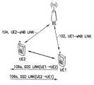
- FIG. 1illustrates the general arrangement of a network access node or BS relative to the UEs which engage in D2D communications.
- the description belowuses examples of D2D ‘pairs’ shown at FIG. 1 as UE 1 and UE 2 .
- the ‘pair’ terminologyis for clarity of explanation and any D2D ‘pair’ detailed below may include more than only two UE devices engaging in D2D communications among themselves.
- the link between UE 1 and the BSis shown as 102 in FIG. 1
- the link between UE 2 and the BSis shown there as 104 .
- direction for those links 102 , 104is stated below as UL or DL.
- the D2D linkcan be considered as two different links depending on direction.
- FIG. 1illustrates the general arrangement of a network access node or BS relative to the UEs which engage in D2D communications.
- FIG. 1illustrates the general arrangement of a network access node or BS relative to the UEs which engage in D2D communications.
- FIG. 1shows the D2D link from UE 1 to UE 2 as 106 a , abbreviated below as D2D (1 ⁇ 2).
- FIG. 1also shows the D2D link from UE 2 to UE 1 as 106 b , abbreviated below as D2D (2 ⁇ 1).
- “Higher layer signaling” noted in the descriptionmeans the signaling originates from either logical layers in the network that are higher than the physical layer (such as the L1 radio resource control layer), or from an entity higher in the network hierarchy than the BS (such as a controller of multiple BSs). Such higher layer signaling may be passed through the physical layer of the BS without changing that such signaling is higher layer signaling.
- FIG. 2illustrates schematically the different latencies for certain different RRM functionalities related to network controlled D2D operation.
- FIG. 4there are separate indications for mode selection, radio resource allocation, slow interference control, and fast interference and link control.
- the communication mode selectionthe network evaluates and decides whether communicating devices shall have direct communication mode (D2D) or conventional cellular communication mode. Because the mode change involves for example synchronization of the protocols and buffers of RLC and PDCP layers, it is necessary to avoid frequent mode changes back and forth. Mode change may be compared to a cellular handover; it is important that once a handover occurs some slight change in relative signal strength does not cause another handover back to the original serving cell.
- FIG. 2shows it on the order of tens to hundreds of milliseconds, which is not a limiting constraint but simply for relative comparison with other latencies.
- the resource allocation and slow interference controlare methods by the eNB to control the D2D connection among cellular and other D2D users. These mechanisms require supporting signaling between the eNB and the D2D pair. Signaling between D2D pair and the eNB reduces efficiency from the D2D communication, because simultaneous control/data transmission to the eNB and to the other D2D device in the pair may not be practical. Thus it may not be feasible to perform resource allocations (scheduling) for the D2D pair as fast as resources are allocated to the cellular users. In practice the semi-persistent scheduling would seem to be the most practical from a scheduling and resource allocation point of view. Regardless, the resource allocation ring of FIG. 2 shows latency on the order of ten to many tens of milliseconds for relative comparison.
- FIG. 2Certain of the functions summarized for FIG. 2 can be divided into operations performed on the network side as shown at FIG. 3 a , and on the device (D2D pair) side as shown at FIG. 3 b . These figures also indicate the main inputs and outputs of the functions.
- mode selectionrequires inputs of QoS metrics, status of the D2D resource allocation, ratio of local data to non-local data at the D2D links, averaged D2D link quality, and averaged UE-eNB link quality. From these the mode selection function outputs the mode selection decision.
- the resource allocation functionuses inputs of scheduling metrics for all devices, received high interference indicator HII and overload indicator OI, D2D resource requests, D2D link quality over some number of PRBs, and UE-eNB link quality over those PRBs to output the resource allocation decision.
- the load indication message sent between eNBs on the X2 interfacecan include the HII and the OI to facilitate coordinating transmit power and scheduling of UEs.
- OImay be considered a reactive indicator, in that it indicates physical layer measurements of the average UL interference plus thermal noise for each PRB (three values for OI in LTE: low, medium and high).
- HIIcan be considered a proactive indicator in that it informs neighbor eNBs that the sending eNB will in the near future schedule UL radio resources for one or more cell-edge UEs, which the neighbor eNBs can use in scheduling their own UEs to help limit any interference.
- the slow interference control function at the network sidetakes inputs of received HII and OI indications, interference measurements at the eNB, interference measurements of the D2D links as well as any requests to update the D2D power offset to output the power offset for the D2D links. And finally the network's fast interference control function takes a measurement of instantaneous interference at the eNB to output an update to the D2D power offset.
- the UE's resource allocation functiontakes the resources given by the eNB as an input to output the resource allocation decision among the D2D devices.
- the UE's slow interference control functiontakes its interference measurements at the D2D link to output a resource request to the eNB, and the UE's fast interference control function takes instantaneous interference measurements at the D2D links as input so as to output any power boosting required for re-transmissions.
- FIGS. 3 a - bdarker input arrows refer to measurement results to be used in every level of RRM functions. This means that the measurement results are needed both in high and low rate RRM functions.
- embodiments of the inventionprovide an efficient and practical measurement procedure that could be utilized in every level of RRM functions.
- the UEssend sounding reference signals to the eNB which enables the eNB can accurately measure the UL channel on which it receives those SRSs.
- Exemplary embodiments detailed hereinadapt a similar SRS procedure for use in power control for D2D communications.
- the eNBsends the SRS configuration of UE 1 to UE 1 .
- the eNBsends the SRS configuration of UE 2 to UE 2 .
- the eNBalso sends at message 402 b the SRS configuration of UE 1 to UE 2 , and sends message 404 a with the SRS configuration of UE 2 to UE 1 .
- the network access node/eNBconfigures both UE 1 and UE 2 for SRSs, and informs each of them of the SRS configuration of the other UE. All of this is done by example on the PDSCH, but alternatively the configurations may be sent on the PDCCH.
- the measurement configuration for D2D paircould indicate the resources and order for the devices to perform a sounding procedure including transmission combining, starting PRB assignment, duration of the SRS, SRS bandwidth, frequency hopping bandwidth, and cyclic shift.
- the eNBsignals the SRS configuration of the two devices in the pair to each device in the pair by higher-layer signaling. This allows the devices UE 1 , UE 2 in the pair to (i) transmit a sounding signal to the eNB in the configured resources for the device—eNB links 102 , 104 to enable channel measurements by the eNB receiver, and (ii) to receive and detect the sounding signal transmitted by the other device in the pair for D2D link channel measurements at the D2D device receiver.
- the first of the above two measurementsis shown at FIG. 4 beginning with UE 1 sending message 406 a to the eNB, where message 406 a has an SRS for which UE 1 was configured via message 402 a .
- the eNBreceives message 406 a and uses the SRS in it to measure at block 408 a the UL eNB-UE 1 channel 102 .
- FIG. 4shows the eNB measuring channel quality and arriving at a CQl for the eNB-UE 1 UL channel 102 but other metrics for channel quality may be used instead as is known in the wireless arts.
- UE 2Since UE 2 also has the SRS configuration of UE 1 from message 402 b , at block 407 a UE 2 also tunes to the resources that UE 1 uses to send message 406 a and measures the CQl or other quality metric using the SRS sent by UE 1 . Since UE 2 hears message 406 a directly from UE 1 , the CQl that UE 2 measures at block 407 a is for the D2D (UE 1 ⁇ UE 2 ) link 106 a.
- D2DUE 1 ⁇ UE 2
- UE 2sends message 406 b to the eNB, where message 406 b has an SRS for which UE 2 was configured via message 404 b .
- the eNBreceives message 406 b and uses the SRS in it to measure at block 408 b the CQl on the UL eNB-UE 2 channel 104 .
- UE 1also has the SRS configuration of UE 2 from message 404 a
- UE 1also tunes to the resources that UE 2 uses to send message 406 b and measures the CQl or other quality metric using the SRS sent by UE 2 . Since UE 1 hears message 406 b directly from UE 2 , the CQl that UE 1 measures at block 407 b is for the D2D (UE 2 ⁇ UE 1 ) link 106 b.
- the CQls for the D2D linksare then accumulated at the eNB.
- UE 1sends the CQl it measured at block 407 b for the D2D (UE 2 ⁇ UE 1 ) link 106 b to the eNB on a PUCCH.
- UE 2sends the CQl it measured at block 407 a for the D2D (UE 1 ⁇ UE 2 ) link 106 a to the eNB on a PUCCH.
- either or both of these messages 410 a , 410 bmay be sent on a PUSCH where the respective CQl is included with the UE's UL data.
- the eNBreceives them, based on those two different D2D link CQIs the eNB computes at block 412 a power offset for the D2D links (D2D power offset), which in an exemplary embodiment will be the same offset for both opposed D2D links between the same UE pair UE 1 , UE 2 .
- D2D power offseta power offset for the D2D links
- the eNBdistributes the D2D power offset that it computed to the UEs.
- FIG. 4shows the specific case in which the power offsets for the opposed D2D links are different; the eNB only needs to distribute the relevant power offset to the respective one of the UEs that is to transmit on that D2D link.
- UE 1transmits on the D2D (UE 1 ⁇ UE 2 ) link 106 a with the power offset for that link which it received at message 414 a .
- UE 2transmits on the D2D (UE 2 ⁇ UE 1 ) link 106 b with the power offset for that link which it received at message 414 b.
- the eNBcomputes the D2D transmission power offset for UL D2D transmission power control to allow maximum D2D transmission power without creating interference to UL cellular transmissions. This may allow spatial re-use of resources for simultaneous D2D and cellular communications on the UL.
- the eNB/networkconfigures the measurement procedure for the D2D pair.
- the D2D devices UE 1 , UE 2would follow certain power control algorithm and rules known and parameterized by the eNB in order to control interference from D2D communications at the eNB's own receiver as well as at neighbor cells' receivers.
- the D2D devices UE 1 , UE 2implement an uplink power control algorithm (which may even be a prior art procedure such as the LTE Release 8/9 power control algorithm). But in this exemplary embodiment the eNB configures an additional power offset, D2D_power_offset, to control the contribution of the certain D2D pair into the cumulative interference seen by the eNB.
- the power for the sounding transmission 406 a , 406 bshall be set as in the cellular mode to reach the eNB, and to prevent near-far problem at eNB as the sounding symbols that the D2D devices UE 1 , UE 2 are sending can be (or can be allowed to be) multiplexed with cellular users via code division multiplexing (for example using a cyclic shift configuration).
- the eNBshall be aware of the path loss of each D2D device UE 1 , UE 2 towards the eNB in order to calculate on how many PRBs the device UE 1 , UE 2 can transmit 406 a , 406 b SRS symbols simultaneously.
- the D2D devices UE 1 , UE 2indicate information to the eNB about the number of PRBs they can transmit on with the current SRS_offset value.
- the D2D sounding procedurecould also be used for fast power adjustment by the eNB.
- the D2D devices UE 1 , UE 2can listen to the downlink resources continuously. After a certain number of slots/TTIs during which the D2D devices UE 1 , UE 2 have transmitted their SRS, in an exemplary embodiment there are downlink fast power control commands sent on the PDCCH by the eNB to decrease transmission power if needed. This is because by sending their SRS, the eNB knows exactly the amount of interference seen by the eNB is contributed by that D2D pair UE 1 , UE 2 .
- the eNBcan differentiate any D2D contribution to interference from inter-cell interference, as well as from other intra-cell D2D pairs and from cellular users sending on the same resource, by measuring the energy of the received symbol with a certain cyclic shift that the eNB has given to the D2D devices UE 1 , UE 2 .
- the end result of thisis that the SRSs that are used for the fast power adjustment will need to include the resources that the D2D pair UE 1 , UE 2 is using currently.
- the eNBconfigures multiple D2D pairs for the same measurement procedure, so that other D2D pairs measure the SRSs sent by one D2D pair at a time to identify which D2D pairs could use the same resources.
- FIG. 4is extended so that the eNB sends the SRS configurations of UE 1 and UE 2 to UE 3 and UE 4 which are engaging in D2D communications separate and distinct from UE 1 and UE 2 .
- UE 3 and UE 4then measure the inter-pair CQls they see and report that information to the eNB.
- UE 1 and UE 2would also be given the SRS configurations for UE 3 and UE 4 , and measure and report similarly.
- the eNBwould use the additional information provided by all four UEs on the inter-pair channel quality to decide if the UE 1 -UE 2 pair can use the same resources for D2D communications as UE 3 and UE 4 .
- Multi-cell extension of the D2D measurement procedureFor now the case of multicell D2D, where devices are attached in cellular mode to different eNBs such that UE 1 and UE 2 are controlled by different serving eNBs.
- the X2 interface between neighbor eNBsis used to negotiate about the measurement procedure among the eNBs to which the devices UE 1 , UE 2 are attached.
- the eNBsuse the X2 interface to indicate to their neighbor eNBs information about their configured D2D measurement procedure so that the informed eNBs could also measure SRSs from the D2D pair at their own receivers.
- An advantage of this alternative embodimentis that for the case where the D2D pair is communicating in a transportation vehicle (such as a bus or train for example), changing the serving cell for the D2D pair becomes simpler in that the serving eNB can provide measurement support for the handover process of the D2D pair UE 1 , UE 2 to the target eNB.
- a transportation vehiclesuch as a bus or train for example
- D2D measurement reportingto the eNB. Recall from FIG. 4 that the UE's quality measurements were reported on PUCCH or PUSCH resources at messages 410 a , 410 b . In an embodiment of the invention where PUCCH resources are used for this reporting, those PUCCH resources are implicitly mapped to the measurement configuration for the reporting D2D device pair UE 1 , UE 2 . Above it was mentioned that describing in the context of D2D device pairs was not limiting. Where there are more than two D2D devices communicating among themselves directly on D2D links, such a grouping of D2D devices is referred to as a cluster of D2D devices.
- those PUCCH resourcesare allocated to the cluster head, which is the D2D device which first combines the clustered D2D device measurements and then reports them to the eNB in a ‘compressed’ report as opposed to each D2D device sending to the eNB its own individual report.
- the D2D measurementsmay be encoded into an efficient D2D CQl format based on a history of D2D measurements, as further detailed below.
- the eNBcan configure how many SRS symbols are bundled and averaged together by the UEs from which the measurement report bearing the CQl is generated. For example, the eNB may setup an on-demand measurement procedure such that it is only used for the various functions shown at FIG. 3 a : for resource allocation, fast interference control or mode selection purposes. Each of those different on-demand purposes would utilize the same procedure but with a different averaging period or different number of SRS symbols.
- exemplary embodiments of the invention as described with reference to FIG. 4can be summarized as using a compressed measurement procedure for the D2D communication integrated into a cellular network by reusing the LTE Release 8/9 SRS transmissions with D2D-specific transmission power settings for the D2D link as well as the links between the individual D2D devices and the eNB which are measured simultaneously.
- D2D power settingscan be used for interference control, resource allocation, fast D2D power adjustment by the network, D2D control and coordination purposes, and also for joint scheduling among D2D and cellular users.
- the setting of D2D power offsetis done by the higher layer signaling initial setup and event-based control, whereas in an exemplary embodiment the fast power control is done by a new D2D transmission power control (TPC) command sent in a new D2D DCI format noted above on the PDCCH at messages 414 a , 414 b during normal D2D operation.
- TPCtransmission power control
- the power TPC commandalone might not be enough to ensure the D2D transmission does not cause near-far interference to cellular UL transmissions received at the eNB receiver.
- the eNBmay have to assign a new D2D offset via higher-layer signaling. This is seen to be more likely to be triggered in a (heterogeneous) pico-micro-macro mixed multi-cell D2D environment.
- the channel quality reportingcould be reduced in one exemplary embodiment by the cluster members comparing the received transmission quality to a predefined threshold (threshold CQl) and report the measurement using only a single bit: one value for the measured CQl being above the threshold and the opposite bit value if the measured CQl is below the value.
- a predefined thresholdthreshold CQl
- the cluster headthen combines the reports and determines for example whether the link qualities in the cluster can meet the quality of service requirements, and/or the measurement reports can be used to check the connectivity of the D2D devices on the various D2D links.
- reportingcan be further reduced for example by informing the eNB only of how many measurements were above or below the threshold.
- reporting overheadis reduced using a traffic based measurement procedure. For example, if a single cluster member is sharing a file over the D2D links to other members, only the links with the file sharer should be reported.
- the measurement reportserves also as a trigger for cluster management.
- the eNBcan determine the connectivity within the cluster itself and use the link quality measurements to find out if some members have bad links with other members.
- the measurement frequency(how often the reference symbols are transmitted, such as messages 406 a and 406 b ) can also be configured so that the overhead is reasonable.
- TAtiming advance
- UE 2can advance its UL receive widow timing by the TA/2 to receive the SRS from UE 1 .
- the D2D CQlcan be based on measurements from D2D device transmissions in D2D mode, as opposed to being based on the SRS as in FIG. 4 .
- Examples of the D2D mode transmissionsinclude the D2D PDSCH, or D2D control signaling with a D2D reference signal.
- This first solutionassumes that the other D2D device UE 2 is transmitting some data or signaling to the first D2D device UE 1 (or devices if clustered), in addition to the SRS for the UE 2 -eNB link channel quality measurements
- Certain exemplary embodiments of the inventionexhibit the technical effect of an efficient and practical measurement scheme for network controlled D2D operation, and reduced UL control signaling payload at least in multi-pair scenarios, and which is adaptable for various different rate RRM functions while still mitigating D2D near-far interference to cellular UL transmissions.
- FIG. 5a wireless network 100 is adapted for communication between a first UE 1 10 and an access node 12 (base station), and also between a second UE 2 11 and the access node 12 .
- the networkmay include a gateway GW/serving mobility entity MME/radio network controller RNC 14 or other radio controller function (not shown) known by various terms in different wireless communication systems.
- the first UE 1 10is detailed but it is understood that the second UE 2 11 has similar functionality and in an embodiment also similar structure.
- the first UE 10includes a data processor (DP) 10 A, a memory (MEM) 10 B that stores a program (PROG) 100 , and a suitable radio frequency (RF) transceiver 10 D coupled to one or more antennas 10 E (one shown) for bidirectional wireless communications over one or more wireless links 15 with the BS 12 .
- the UE 10may have simultaneous communication over the D2D link 16 with the other UE 11 , and the BS 12 .
- the simultaneous communicationcan take place on separate resources, e.g. different frequency blocks or using the same resources utilizing further transceivers and/or antennas. Each of the links can have different or even independent maximum transmit power.
- the second UE 11 as well as additional UEsare similarly configured as is shown at FIG. 5 for the first UE 10 .
- connectionmeans any connection or coupling, either direct or indirect, between two or more elements, and may encompass the presence of one or more intermediate elements between two elements that are “connected” or “coupled” together.
- the coupling or connection between the elementscan be physical, logical, or a combination thereof.
- two elementsmay be considered to be “connected” or “coupled” together by the use of one or more wires, cables and printed electrical connections, as well as by the use of electromagnetic energy, such as electromagnetic energy having wavelengths in the radio frequency region, the microwave region and the optical (both visible and invisible) region, as non-limiting examples.
- the BS 12also includes a DP 12 A, a MEM 12 B, that stores a PROG 12 C, and a suitable RF transceiver 12 D coupled to one or more antennas 12 E.
- the BS 12may be coupled via a data path 18 (wired or wireless) to the Internet, a mobile switching center, or other broader network, which may be via a serving or other GW/MME/RNC 14 .
- the GW/MME/RNCalso includes a DP 14 A, a MEM 14 B that stores a PROG 14 C, and a suitable modem and/or transceiver (not shown) for communication with the BS 12 over the data link 18 .
- At least one of the PROGs 10 C and 12 Cis assumed to include program instructions that, when executed by the associated DP, enable the electronic device to operate in accordance with the exemplary embodiments of this invention, as detailed above.
- Inherent in the DPs 10 A and 12 Ais a clock to enable synchronism among the various apparatus for transmissions and receptions within the appropriate time intervals and slots required.
- the PROGs 10 C and 12 Cmay be embodied in software, firmware and/or hardware, as is appropriate.
- the exemplary embodiments of this inventionmay be implemented by computer software stored in the MEM 12 B and executable by the DP 12 A of the BS 12 and similar for the other MEM 10 B and DP 10 A of the UE 10 (and the other UEs 11 detailed above), or by hardware, or by a combination of software and/or firmware and hardware in any or all of the devices shown.
- the various embodiments of the UE 10 , 11can include, but are not limited to, mobile stations, cellular telephones, personal digital assistants (PDAs) having wireless communication capabilities, portable computers having wireless communication capabilities, image capture devices such as digital cameras having wireless communication capabilities, gaming devices having wireless communication capabilities, music storage and playback appliances having wireless communication capabilities, Internet appliances permitting wireless Internet access and browsing, as well as portable units or terminals that incorporate combinations of such functions.
- PDAspersonal digital assistants
- portable computershaving wireless communication capabilities
- image capture devicessuch as digital cameras having wireless communication capabilities
- gaming deviceshaving wireless communication capabilities
- music storage and playback applianceshaving wireless communication capabilities
- Internet appliancespermitting wireless Internet access and browsing, as well as portable units or terminals that incorporate combinations of such functions.
- the MEMs 10 B and 12 Bmay be of any type suitable to the local technical environment and may be implemented using any suitable data storage technology, such as semiconductor-based memory devices, magnetic memory devices and systems, optical memory devices and systems, fixed memory and removable memory.
- the DPs 10 A and 12 Amay be of any type suitable to the local technical environment, and may include one or more of general purpose computers, special purpose computers, microprocessors, digital signal processors (DSPs) and processors based on a multi-core processor architecture, as non-limiting examples.
- channel quality on a wireless link between a first device and a second deviceis determined from signaling sent from the first device UE 1 to a network access node eNB.
- eNBnetwork access node
- Blocks 606 , 608 , 610 , 612 and 614are each from the perspective of the network access node. From that perspective, determining the channel quality comprises at block 606 receiving from the second device UE 2 a channel quality indicator for the wireless link which is a D2D link from the first device UE 1 to the second device UE 2 ; and causing the adjustment to the transmit power comprises the network access node eNB using the received channel quality indicator to determine the adjustment to transmit power which is a power offset, and sending to the second device UE 2 an indication of the power offset for use on a D2D link from the second device to the first device.
- the channel quality indicatoris received from the first device on a physical uplink control channel PUCCH that implicitly maps to a pairing of the first device with at least the second device for D2D communications with one another.
- the channel quality indicatoris received from the first device on a physical uplink shared channel PUSCH that is allocated for a pairing of the first device with at least the second device for D2D communications with one another.
- the network access nodedetermines pathloss on a link between the network access node and the second device using a sounding reference signal received from the second device; and uses the determined pathloss and the received channel quality indicator to determine the power offset.
- Blocks 616 , 618 and 620are from the perspective of the second device.
- determining the channel quality of block 602comprises measuring channel quality from a reference signal that is sent by the first device to the network node, and using the measured channel quality to select a channel quality indicator for the wireless link which is a D2D link from the first device to the second device.
- causing the adjustment to the transmit power at block 604comprises directly adjusting transmit power by the second device on a D2D link from the second device to the first device using an indication of power offset that is received from the network access node in response to the second device sending to the network access node the channel quality indicator.
- the second devicefurther receives from the network access node a sounding reference signal configuration for the first device and a sounding reference signal configuration for the second device; and uses the received sounding reference signal configuration for the first device to find and monitor the reference signal that is sent by the first device to the network node.
- the second devicefurther receives from the network access node an indication of how many sounding reference signals to bundle and average for measuring the channel quality from which is selected the channel quality indicator.
- Exemplary process steps for another embodiment of the inventionare shown at FIG. 7 .
- the cluster head or first devicereceives from at least one other device with which the cluster head/first device has a wireless device-to-device link, a quality indicator for the respective D2D link observed by the respective other device.
- the cluster headcompiles those received quality indicators into a compressed report.
- the cluster head/first deviceis part of the D2D cluster, which in an embodiment may include only a total of two devices (cluster head plus one other).
- the cluster headcompiles, into the compressed report, the quality indicators received from each of the respective other device or devices along with a respective additional quality indicator or indicators of the respective D2D link or links that are observed by the cluster head/first device. Then at block 706 the cluster head/first device sends the compressed report to a network entity/eNB.
- the cluster headreceives all of the CQl indicators detailed for messages 410 a and 410 b in FIG. 4 , and compiles those quality indicators into a compressed report which the cluster head sends at block 706 to the eNB, rather than each D2D device separately sending to the eNB its own observed CQl.
- each respective additional quality indicator of each of the respective D2D link or links observed by the cluster head/first deviceis determined at block 708 by listening to a SRS sent by the respective other device or devices to the network entity on a PUCCH as shown at FIG. 4 .
- each of those received quality indicatorsis a single bit, indicating whether quality of the respective link is above or below a threshold.
- the compressed report of block 706may include at block 712 an indication of how many of the quality indicators were either above or below the threshold of block 710 , but not include the respective quality indicators themselves; or in an embodiment at block 714 the compressed report of block 706 does include the respective quality indicators themselves.
- the cluster head/first deviceutilizes the quality indicators to determine whether the respective links can meet quality of service requirements for D2D communications, and/or in another embodiment at block 718 the cluster head/first device utilizes the quality indicators to check connectivity over the respective links, and takes action in response to determining that any of the other devices lacks connectivity over its respective link.
- Such actionincludes, by non-limiting example, dropping the respective device from the cluster, or establishing the respective device back in the cluster using new D2D links.
- that cluster head/first devicealso receives at block 720 further quality indicators for D2D links that go between other D2D device pairs that do not include the cluster head/first device. Such further quality indicators are compiled into the compressed report of block 704 .
- the term ‘further’ quality indicators for these D2D links that do not involved the cluster headis used to distinguish from the ‘additional’ quality indicators that are for the D2D links between the cluster head itself and any other D2D device.
- the ‘additional’ quality indicatorsare for the D2D links observed by the cluster head directly.
- the indication at block 712informs of how many of the total D2D links are above or below the threshold, including additional and further quality indicators. More generally, the quality indicators of FIG. 7 are not limited to only D2D links.
- the various embodimentsmay be implemented in hardware or special purpose circuits, software (computer readable instructions embodied on a computer readable medium), logic or any combination thereof.
- some aspectsmay be implemented in hardware, while other aspects may be implemented in firmware or software which may be executed by a controller, microprocessor or other computing device, although the invention is not limited thereto.
- firmware or softwarewhich may be executed by a controller, microprocessor or other computing device, although the invention is not limited thereto.
- While various aspects of the inventionmay be illustrated and described as block diagrams, flow charts, or using some other pictorial representation, it is well understood that these blocks, apparatus, systems, techniques or methods described herein may be implemented in, as non-limiting examples, hardware, software, firmware, special purpose circuits or logic, general purpose hardware or controller or other computing devices, or some combination thereof.
- Embodiments of the inventionsmay be practiced in various components such as integrated circuit modules.
- the design of integrated circuitsis by and large a highly automated process.
- Complex and powerful software toolsare available for converting a logic level design into a semiconductor circuit design ready to be etched and formed on a semiconductor substrate.
- Programswhich automatically route conductors and locate components on a semiconductor chip using well established rules of design as well as libraries of pre-stored design modules.
- the resultant designin a standardized electronic format (e.g., Opus, GDSII, or the like) may be transmitted to a semiconductor fabrication facility or “fab” for fabrication.
Landscapes
- Engineering & Computer Science (AREA)
- Computer Networks & Wireless Communication (AREA)
- Signal Processing (AREA)
- Mobile Radio Communication Systems (AREA)
Abstract
Description
- BS base station (e.g., any generic network access node)
- C-RNTI cell radio network temporary identifier
- D2D device-to-device
- DL downlink
- eNB base station in an LTE/LTE-A system
- E-UTRAN evolved UTRAN
- LTE long term evolution of UTRAN (also known as 3.9G)
- LTE-A LTE advanced
- OFDM orthogonal frequency division multiplex
- PRB physical resource block
- QoS quality of service
- RRM radio resource management
- SRS sounding reference signal
- TTI transmission time interval
- UE user equipment (e.g., mobile or subscriber station SS/MS, terminal)
- UL uplink
- UMTS universal mobile telecommunications system
- UTRAN UMTS terrestrial radio access network
- WiMAX worldwide interoperability for microwave access
- power_in_cellular_mode˜P—0+PL;
- power_in_SRS_transmission˜P—0+PL+SRS_offset;
- power_in_D2D_mode˜P—0+PL+D2D_power_offset;
where P—0 is the base power setting, PL is the path loss between the device UE1 or UE2 and the serving eNB, SRS_offset is controlled by the eNB so its received power from multiple UEs is roughly equal, and D2D_power_offset is described atFIG. 4 but as defined immediately above power_in_D2D_mode takes into account the cumulative power seen by the eNB. SRS_offset could be set similarly to cellular users to allow the same level of received power at the eNB for cellular and D2D users, as further detailed below.
Claims (14)
Priority Applications (4)
| Application Number | Priority Date | Filing Date | Title |
|---|---|---|---|
| US12/774,994US8504052B2 (en) | 2010-05-06 | 2010-05-06 | Measurements and fast power adjustments in D2D communications |
| PCT/FI2011/050168WO2011138495A1 (en) | 2010-05-06 | 2011-02-24 | Measurements and fast power adjustments in d2d communications |
| EP11777317.6AEP2567586A4 (en) | 2010-05-06 | 2011-02-24 | Measurements and fast power adjustments in d2d communications |
| CN201180015407.6ACN102823311B (en) | 2010-05-06 | 2011-02-24 | Measurements and fast power adjustments in D2D communications |
Applications Claiming Priority (1)
| Application Number | Priority Date | Filing Date | Title |
|---|---|---|---|
| US12/774,994US8504052B2 (en) | 2010-05-06 | 2010-05-06 | Measurements and fast power adjustments in D2D communications |
Publications (2)
| Publication Number | Publication Date |
|---|---|
| US20110275382A1 US20110275382A1 (en) | 2011-11-10 |
| US8504052B2true US8504052B2 (en) | 2013-08-06 |
Family
ID=44902272
Family Applications (1)
| Application Number | Title | Priority Date | Filing Date |
|---|---|---|---|
| US12/774,994Expired - Fee RelatedUS8504052B2 (en) | 2010-05-06 | 2010-05-06 | Measurements and fast power adjustments in D2D communications |
Country Status (4)
| Country | Link |
|---|---|
| US (1) | US8504052B2 (en) |
| EP (1) | EP2567586A4 (en) |
| CN (1) | CN102823311B (en) |
| WO (1) | WO2011138495A1 (en) |
Cited By (19)
| Publication number | Priority date | Publication date | Assignee | Title |
|---|---|---|---|---|
| US20130016646A1 (en)* | 2011-07-12 | 2013-01-17 | Electronics And Telecommunications Research Institute | Terminal of supporting direct communication using infra communication and direct communication method of the same |
| US20130157679A1 (en)* | 2010-05-28 | 2013-06-20 | Vinh Van Phan | Quality of Service Management in Radio Network |
| US20130235754A1 (en)* | 2010-10-28 | 2013-09-12 | Lg Electronics Inc. | Method and apparatus for measuring a channel status between terminals in a wireless access system that supports cooperative communication |
| US20130295976A1 (en)* | 2012-05-04 | 2013-11-07 | Qualcomm Incorporated | Method and apparatus for reducing interference in a wireless system |
| US20140003262A1 (en)* | 2012-07-02 | 2014-01-02 | Hong He | Sounding reference signal (srs) mechanism for intracell device-to-device (d2d) communication |
| US20140010209A1 (en)* | 2010-08-27 | 2014-01-09 | Nokia Corporation | Methods and apparatuses for facilitating quality of service control |
| US20140086157A1 (en)* | 2012-09-26 | 2014-03-27 | Chandra Sekhar Bontu | Transmit power adjustment for inter-device communication in wireless communication systems |
| US20150156757A1 (en)* | 2012-05-23 | 2015-06-04 | Kyocera Corporation | Transmission of device-to-device (d2d) control data from a first d2d device to a second d2d device in a cellular communication system |
| US20150163705A1 (en)* | 2013-05-16 | 2015-06-11 | Telefonaktiebolaget L M Ericsson (Publ) | Wireless Device, Network Nodes and Methods Therein for Handling a Device-to-Device (D2D) Communication during Handover in a Wireless Telecommunications Network |
| US20160198339A1 (en)* | 2014-08-11 | 2016-07-07 | Telefonaktiebolaget L M Ericsson (Publ) | D2D and Cellular Operation on Different Carrier Frequencies or Frequency Bands |
| US20160249297A1 (en)* | 2013-10-08 | 2016-08-25 | Samsung Electronics Co., Ltd. | Method and apparatus for transmit signal power control and discovery signal resource multiplexing in wireless communication system |
| US20170150491A1 (en)* | 2014-08-08 | 2017-05-25 | Huawei Technologies Co., Ltd. | Method and Apparatus for Reporting Terminal Device Capability |
| US9825840B2 (en) | 2015-07-17 | 2017-11-21 | Qualcomm Incorporated | Link-quality-based resource allocation in device-to-device communications |
| US9883426B2 (en) | 2014-07-31 | 2018-01-30 | Microsoft Technology Licensing, Llc. | Enhanced reporting for handover in device-to-device communication |
| US9986513B1 (en)* | 2016-12-31 | 2018-05-29 | Sprint Communications Company L.P. | Device to-device (D2D) transmission power control |
| US10264535B2 (en) | 2013-09-11 | 2019-04-16 | Samsung Electronics Co., Ltd | Method and apparatus for controlling transmission signal power by terminal in wireless communication system |
| US10382989B2 (en)* | 2015-06-01 | 2019-08-13 | Lg Electronics Inc. | D2D operation method performed by UE in wireless communication system and UE using same method |
| US10833832B2 (en) | 2016-06-22 | 2020-11-10 | Intel Corporation | Communication device and a method for full duplex scheduling |
| US20220326345A1 (en)* | 2019-12-25 | 2022-10-13 | Huawei Technologies Co., Ltd. | Detection signal transmitting method and apparatus, and storage medium |
Families Citing this family (152)
| Publication number | Priority date | Publication date | Assignee | Title |
|---|---|---|---|---|
| US10517098B2 (en)* | 2010-07-30 | 2019-12-24 | Qualcomm Incorporated | Interference coordination for peer-to-peer (P2P) communication and wide area network (WAN) communication |
| CN102387563B (en) | 2010-08-26 | 2015-05-27 | 华为技术有限公司 | Service control method and related device and system of machine type communication equipment |
| EP2636229B1 (en)* | 2010-11-04 | 2017-08-30 | InterDigital Patent Holdings, Inc. | Method and apparatus for establishing peer-to-peer communication |
| EP2647175B1 (en)* | 2010-12-03 | 2018-04-04 | Nokia Technologies Oy | Facilitating device-to-device communication |
| US9775135B2 (en)* | 2011-03-18 | 2017-09-26 | Lg Electronics Inc. | Method and device for communicating device-to-device |
| CN103460780B (en)* | 2011-03-31 | 2017-11-14 | 安华高科技通用Ip(新加坡)公司 | Method and apparatus for promoting device-to-device to communicate |
| WO2012138165A2 (en)* | 2011-04-07 | 2012-10-11 | 엘지전자 주식회사 | Method and apparatus for monitoring a paging message in m2m communications |
| WO2012150815A2 (en)* | 2011-05-02 | 2012-11-08 | 엘지전자 주식회사 | Method for performing device-to-device communication in wireless access system and apparatus therefor |
| JP5357207B2 (en)* | 2011-05-18 | 2013-12-04 | 株式会社エヌ・ティ・ティ・ドコモ | Mobile communication method |
| WO2012159270A1 (en)* | 2011-05-25 | 2012-11-29 | Renesas Mobile Corporation | Resource allocation for d2d communication |
| EP2753122B1 (en)* | 2011-08-31 | 2020-04-01 | LG Electronics Inc. | Method for performing a change of mode in devices directly communicating with each other in a wireless connection system, and apparatus for same |
| JP2015502084A (en) | 2011-11-14 | 2015-01-19 | 京セラ株式会社 | Inter-terminal communication management using macrocell communication resources |
| WO2013073915A1 (en)* | 2011-11-18 | 2013-05-23 | 엘지전자 주식회사 | Method for requesting device-to-device communication in wireless access system and apparatus for same |
| CN103139889B (en)* | 2011-11-28 | 2015-09-09 | 华为技术有限公司 | The Poewr control method of D2D, subscriber equipment, base station and communication system |
| US9344954B2 (en)* | 2011-12-05 | 2016-05-17 | Lg Electronics Inc. | Method for detecting a signal for direct communication between UE's in a wireless communication system and apparatus for same |
| KR20130063615A (en)* | 2011-12-07 | 2013-06-17 | 한국전자통신연구원 | Method for controlling communication resource of device to device in cellular communication system |
| EP2795825A1 (en)* | 2011-12-21 | 2014-10-29 | Nokia Solutions and Networks Oy | Method, apparatus and computer program for providing sounding reference signals for coordinated multipoint transmissions |
| WO2013100831A1 (en) | 2011-12-29 | 2013-07-04 | Telefonaktiebolaget L M Ericsson (Publ) | A user equipment and a radio network node, and methods therein |
| EP2627116A1 (en)* | 2012-02-13 | 2013-08-14 | Alcatel Lucent | Method for selecting a feedback mode for a wireless transmission, first network node, and second network node thereof |
| US9531527B2 (en) | 2012-02-17 | 2016-12-27 | Lg Electronics Inc. | Method and apparatus for transmitting signals of user equipment (UE) configured to perform D2D communication in wireless communication system |
| US9883496B2 (en) | 2012-03-06 | 2018-01-30 | Lg Electronics Inc. | Method and apparatus for transmitting/receiving control information for device to device (D2D) communication in a wireless communications system |
| US10075927B2 (en)* | 2012-03-12 | 2018-09-11 | Lg Electronics Inc. | Method for transmitting and receiving control information and apparatus for same |
| US9338807B2 (en)* | 2012-03-19 | 2016-05-10 | Futurewei Technologies, Inc. | System and method for direct mobile communications power control |
| CN104335631B (en)* | 2012-04-09 | 2018-06-19 | 瑞典爱立信有限公司 | For enhancing the method and apparatus of network positions measurement performance by management uncertain measurement opportunity |
| US9143984B2 (en) | 2012-04-13 | 2015-09-22 | Intel Corporation | Mapping of enhanced physical downlink control channels in a wireless communication network |
| KR102110214B1 (en)* | 2012-04-26 | 2020-05-13 | 한국전자통신연구원 | Method for device to device communication based on partial operation control of device |
| US9554408B2 (en) | 2012-05-11 | 2017-01-24 | Kyocera Corporation | Device discovery management using peer device relationships for device-to-device (D2D) communication |
| EP2665326B1 (en)* | 2012-05-15 | 2017-12-13 | Telefonaktiebolaget LM Ericsson (publ) | Apparatus and method thereof for setting up device-to-device communication |
| CN103428712B (en) | 2012-05-16 | 2016-08-10 | 华为技术有限公司 | A kind of intercepting method and node |
| US9084203B2 (en) | 2012-05-21 | 2015-07-14 | Qualcomm Incorporated | Methods and apparatus for providing transmit power control for devices engaged in D2D communications |
| WO2013181421A2 (en)* | 2012-05-31 | 2013-12-05 | Interdigital Patent Holdings, Inc. | Method and apparatus for device-to-device (d2d) mobility in wireless systems |
| EP2856812A2 (en) | 2012-05-31 | 2015-04-08 | Interdigital Patent Holdings, Inc. | Device-to-device (d2d) cross link power control |
| CN103457690B (en) | 2012-05-31 | 2017-11-03 | 中兴通讯股份有限公司 | Transmission method, apparatus and system and the user equipment of detection reference signal |
| WO2013181394A1 (en)* | 2012-05-31 | 2013-12-05 | Interdigital Patent Holdings, Inc. | Device-to-device (d2d) link adaptation |
| CN103476102B (en)* | 2012-06-06 | 2016-08-17 | 华为技术有限公司 | A kind of terminal and terminal D 2D communication means and terminal, system |
| US20150139176A1 (en)* | 2012-06-06 | 2015-05-21 | Kyocera Corporation | Mobile communication system and user terminal |
| JP6132840B2 (en)* | 2012-06-06 | 2017-05-24 | 京セラ株式会社 | Communication control method, user terminal, processor, and storage medium |
| US9578665B2 (en)* | 2012-06-06 | 2017-02-21 | Nec (China) Co., Ltd. | Method and apparatus for performing D2D communication |
| KR101924830B1 (en)* | 2012-06-19 | 2019-02-27 | 삼성전자주식회사 | Method and apparatus for synchronizing of terminal in wireless communication network |
| KR102138532B1 (en)* | 2012-06-22 | 2020-07-28 | 엘지전자 주식회사 | Scheduling method for device-to-device communication and apparatus for same |
| US8737276B2 (en) | 2012-06-27 | 2014-05-27 | Qualcomm Incorporated | Method and apparatus using modified subframes |
| EP2868020B1 (en)* | 2012-06-28 | 2018-04-25 | Telefonaktiebolaget LM Ericsson (publ) | Method and base station for link adaptation of pdcch in a radio communication system |
| WO2014010956A1 (en)* | 2012-07-13 | 2014-01-16 | 한국전자통신연구원 | Discovery method for device to device communication between terminals |
| JP5922845B2 (en) | 2012-07-18 | 2016-05-24 | 京セラ株式会社 | Inter-device communication interference management in cellular communication systems |
| JP5893141B2 (en)* | 2012-07-27 | 2016-03-23 | 京セラ株式会社 | Mobile communication system, user terminal, processor, and base station |
| JP6154377B2 (en)* | 2012-07-27 | 2017-06-28 | 京セラ株式会社 | Mobile communication system, mobile communication method, radio base station, radio terminal, and processor |
| US9398630B2 (en) | 2012-08-10 | 2016-07-19 | Alcatel Lucent | Methods and apparatuses for controlling and scheduling device-to-device communications |
| EP2888898A4 (en)* | 2012-08-27 | 2016-04-06 | Ericsson Telefon Ab L M | Link adaptation for device-to-device communication |
| US9591679B2 (en) | 2012-09-17 | 2017-03-07 | Blackberry Limited | Initiation of inter-device communication in wireless communication systems |
| US9826381B2 (en) | 2012-09-18 | 2017-11-21 | Blackberry Limited | Device handshake/discovery for inter-device communication in wireless communication systems |
| RU2626086C2 (en) | 2012-09-19 | 2017-07-21 | Телефонактиеболагет Л М Эрикссон (Пабл) | Network node and method of controlling maximum levels of transmission power for d2d communication line |
| US8982895B2 (en) | 2012-09-21 | 2015-03-17 | Blackberry Limited | Inter-device communication in wireless communication systems |
| US9014113B2 (en) | 2012-09-21 | 2015-04-21 | Blackberry Limited | User equipment architecture for inter-device communication in wireless communication systems |
| CN103702346A (en)* | 2012-09-27 | 2014-04-02 | 中兴通讯股份有限公司 | Method and device for measuring condition of channel between D2D (device-to-device) user equipment |
| WO2014050887A1 (en)* | 2012-09-27 | 2014-04-03 | 京セラ株式会社 | Mobile communication system, user terminal, base station, and processor |
| US9973315B2 (en) | 2012-09-28 | 2018-05-15 | Intel Corporation | Systems and methods for semi-persistent scheduling of wireless communications |
| US9173124B2 (en)* | 2012-09-28 | 2015-10-27 | Intel Corporation | Systems and methods for wireless signal measurement and reporting for device to-device communication |
| EP2904874B1 (en)* | 2012-10-05 | 2018-12-05 | Telefonaktiebolaget LM Ericsson (publ) | Methods and arrangements for network assisted device-to-device communication |
| US10477570B2 (en)* | 2012-10-08 | 2019-11-12 | Kyocera Corporation | Advance communication resource notification in wireless communication systems having overlapping service areas |
| US9137836B2 (en)* | 2012-10-15 | 2015-09-15 | Blackberry Limited | Inter-device communication authorization and data sniffing in wireless communication systems |
| US9407302B2 (en)* | 2012-12-03 | 2016-08-02 | Intel Corporation | Communication device, mobile terminal, method for requesting information and method for providing information |
| EP2928241B1 (en)* | 2012-12-03 | 2021-05-05 | Sony Corporation | Communication control device, program, and communication control method |
| US20140160946A1 (en)* | 2012-12-06 | 2014-06-12 | Qualcomm Incorporated | Methods and apparatus for improving centralized d2d scheduling |
| US9516659B2 (en)* | 2012-12-06 | 2016-12-06 | Intel Corporation | Carrier type (NCT) information embedded in synchronization signal |
| US9226289B2 (en)* | 2012-12-18 | 2015-12-29 | Qualcomm Incorporated | Systems and methods to conserve power of machine-to-machine devices using a shared data channel |
| US9301308B2 (en)* | 2012-12-21 | 2016-03-29 | Telefonaktiebolaget L M Ericsson (Publ) | Determining a cluster set of mobile devices |
| CN103067132B (en)* | 2012-12-28 | 2015-09-23 | 华为技术有限公司 | Channel detection method, communication means, terminal and system |
| US20150358981A1 (en)* | 2013-01-07 | 2015-12-10 | Lg Electronics Inc. | Method and apparatus for performing device-to-device communication in wireless communication system |
| CN103974290A (en)* | 2013-01-24 | 2014-08-06 | 中兴通讯股份有限公司 | D2D service quality processing method and device |
| US9986380B2 (en) | 2013-01-25 | 2018-05-29 | Blackberry Limited | Proximity and interest determination by a wireless device |
| US9125101B2 (en)* | 2013-03-08 | 2015-09-01 | Intel Corporation | Distributed power control for D2D communications |
| WO2014134831A1 (en)* | 2013-03-08 | 2014-09-12 | Nokia Corporation | Method and apparatus for handover of device-to-device communications |
| US9031612B2 (en)* | 2013-03-13 | 2015-05-12 | Intel Corporation | Spatial alignment for D2D interference mitigation |
| US9706481B2 (en)* | 2013-03-15 | 2017-07-11 | Futurewei Technologies, Inc. | System and method for time-power frequency hopping for D2D discovery |
| EP2782287A1 (en)* | 2013-03-20 | 2014-09-24 | Alcatel Lucent | Methods and devices for network assisted beaconing |
| GB2512399A (en) | 2013-03-28 | 2014-10-01 | Nec Corp | Direct communication between mobile radio communication devices |
| US9826391B2 (en) | 2013-03-29 | 2017-11-21 | Intel IP Corporation | Low power device to device transmission |
| US9398062B2 (en)* | 2013-03-29 | 2016-07-19 | Intel IP Corporation | Timing synchronization in discovery signals |
| FR3004309B1 (en)* | 2013-04-08 | 2017-03-24 | Thales Sa | DISTRIBUTED METHOD FOR SELECTING A CONFIGURATION IN MOBILE NETWORKS |
| CN104105181B (en)* | 2013-04-10 | 2018-06-05 | 电信科学技术研究院 | A kind of Poewr control method and equipment of D2D transmission |
| US9635646B2 (en)* | 2013-04-17 | 2017-04-25 | Qualcomm Incorporated | Method and apparatus for configuring uplink and downlink serving cells in wireless communications |
| CN104144426A (en)* | 2013-05-07 | 2014-11-12 | 中兴通讯股份有限公司 | Method and base station for device-to-device (D2D) users to dynamically multiplex cellular user resources |
| US10098129B2 (en) | 2013-05-08 | 2018-10-09 | Telefonaktiebolaget Lm Ericsson (Publ) | Handling of simultaneous network communication transmission and D2D communication reception or simultaneous network communication reception and D2D communication transmission |
| EP2995159B1 (en)* | 2013-05-08 | 2019-02-20 | Telefonaktiebolaget LM Ericsson (publ) | Improved selection of scheduling policy for network communications links and d2d communications links |
| US9749966B2 (en) | 2013-05-08 | 2017-08-29 | Telefonaktiebolaget Lm Ericsson (Publ) | Handling of simultaneous network communication transmission and D2D communication transmission |
| WO2014181440A1 (en)* | 2013-05-09 | 2014-11-13 | 富士通株式会社 | Communication system, base station, terminal, and control method |
| CN105122934B (en)* | 2013-05-10 | 2019-08-20 | 上海诺基亚贝尔股份有限公司 | Neighbor discovery method, device and user equipment under no network coverage |
| CN104219675A (en)* | 2013-05-30 | 2014-12-17 | 中兴通讯股份有限公司 | Management method and system of discovery information resource between communication nodes |
| KR102168851B1 (en)* | 2013-06-13 | 2020-10-23 | 삼성전자주식회사 | A METHOD AND APPARATUS FOR RESOURCE ALLOCATION of A D2D COMMUNICATION |
| CN104244392B (en)* | 2013-06-24 | 2017-12-29 | 华为技术有限公司 | D2D transmission is avoided to cause method, base station and the user equipment of uplink interference |
| JP2015012404A (en)* | 2013-06-27 | 2015-01-19 | 京セラ株式会社 | Communication control method, base station, and user terminal |
| US9794870B2 (en) | 2013-06-28 | 2017-10-17 | Intel Corporation | User equipment and method for user equipment feedback of flow-to-rat mapping preferences |
| US9814037B2 (en) | 2013-06-28 | 2017-11-07 | Intel Corporation | Method for efficient channel estimation and beamforming in FDD system by exploiting uplink-downlink correspondence |
| WO2015002433A1 (en)* | 2013-07-01 | 2015-01-08 | 엘지전자 주식회사 | D2d signal transmission method and user equipment |
| US9325480B2 (en) | 2013-07-10 | 2016-04-26 | Google Technology Holdings LLC | Methods and device for performing device-to-device communication |
| JP6166469B2 (en)* | 2013-07-12 | 2017-07-19 | 華為技術有限公司Huawei Technologies Co.,Ltd. | Method and apparatus for triggering multi-UE coordinated communication |
| CN104349402A (en)* | 2013-07-24 | 2015-02-11 | 中兴通讯股份有限公司 | Terminal switching method supporting D2D technology, communication node, terminal and system |
| CA2918072A1 (en)* | 2013-07-29 | 2015-02-05 | Fujitsu Limited | Power control method, ue and communication system |
| WO2015014395A1 (en)* | 2013-07-31 | 2015-02-05 | Telecom Italia S.P.A. | Device-to-device communication management in mobile communication networks |
| GB201314080D0 (en) | 2013-08-06 | 2013-09-18 | Nec Corp | Communication system,apparatus and related methods of operation |
| CN105453627B (en)* | 2013-08-06 | 2019-10-15 | 夏普株式会社 | Terminal device, communication method, and integrated circuit |
| JP6155501B2 (en)* | 2013-08-06 | 2017-07-05 | シャープ株式会社 | Terminal device, base station device, and wireless communication method |
| KR102100837B1 (en)* | 2013-08-08 | 2020-04-14 | 삼성전자주식회사 | Communication method and apparatus for device-to-device(d2d) |
| CN104349437B (en)* | 2013-08-09 | 2018-10-19 | 上海诺基亚贝尔股份有限公司 | Method for inhibiting interference and user equipment |
| KR102059135B1 (en)* | 2013-08-14 | 2019-12-24 | 삼성전자주식회사 | Apparatus and method for transmission control for device to device communication in wireless communication system |
| CN105492925B (en)* | 2013-08-29 | 2017-08-15 | Lg电子株式会社 | Method and device for measuring distance between terminals based on device-to-device direct communication in wireless communication system |
| US9893933B2 (en)* | 2013-09-25 | 2018-02-13 | Nokia Solutions And Networks Management International Gmbh | Configuration of channel estimation related parameters |
| EP3061298A4 (en)* | 2013-10-23 | 2017-05-24 | Telefonaktiebolaget LM Ericsson (publ) | A network node and method for handling cellular and d2d communications in a wireless communications network |
| JP6245270B2 (en)* | 2013-10-28 | 2017-12-13 | 富士通株式会社 | Wireless communication method, wireless communication system, wireless station, and wireless terminal |
| US9392468B1 (en)* | 2013-10-30 | 2016-07-12 | Sprint Communications Company L.P. | Adaptive beamforming techniques in long term evolution networks |
| CN103716869B (en)* | 2013-12-12 | 2016-12-07 | 浙江工业大学 | A kind of distributed power control method optimized based on efficiency in D2D communication |
| US9723575B2 (en)* | 2014-01-27 | 2017-08-01 | Sun Patent Trust | Wireless device and power control method |
| US10136347B2 (en) | 2014-01-29 | 2018-11-20 | Lg Electronics Inc. | Method for reporting state of relay function performed by terminal in radio communication system and terminal using same |
| EP3105957B1 (en) | 2014-02-10 | 2019-04-03 | LG Electronics Inc. | Method and apparatus for indicating qos of d2d data in wireless communication system |
| EP3113386A4 (en)* | 2014-03-18 | 2017-04-12 | Huawei Technologies Co., Ltd. | Network listening method and device |
| NO2710652T3 (en)* | 2014-03-18 | 2018-03-17 | ||
| GB2524301A (en)* | 2014-03-19 | 2015-09-23 | Nec Corp | Communication system |
| US9642099B2 (en) | 2014-05-08 | 2017-05-02 | Futurewei Technologies, Inc. | System and method for power control command for device-to-device transmissions |
| EP3021530B1 (en)* | 2014-05-28 | 2018-09-05 | Huawei Technologies Co., Ltd. | Data sending method and device |
| CN112491734A (en)* | 2014-05-30 | 2021-03-12 | 索尼公司 | Electronic device and data transmission method |
| JP6377773B2 (en) | 2014-06-13 | 2018-08-22 | 京セラ株式会社 | Selection between cellular communication link and inter-device (D2D) communication link for communication between user equipment (UE) devices |
| CN105338464B (en)* | 2014-06-17 | 2020-10-20 | 索尼公司 | Electronic device and wireless communication method on user equipment side in wireless communication system |
| JP2017527150A (en)* | 2014-06-17 | 2017-09-14 | 華為技術有限公司Huawei Technologies Co.,Ltd. | Communication method and communication apparatus |
| CN110072252B (en)* | 2014-06-27 | 2022-07-08 | Lg电子株式会社 | Method and apparatus for measuring device terminal by device in wireless communication system |
| US9608690B2 (en)* | 2014-07-17 | 2017-03-28 | Qualcomm Incorporated | Type 1 and type 2 hopping for device-to-device communications |
| KR102280577B1 (en)* | 2014-08-01 | 2021-07-23 | 삼성전자 주식회사 | Transmission Power Control Method in D2D communication and Apparatus thereof |
| JP6554656B2 (en)* | 2014-08-07 | 2019-08-07 | サン パテント トラスト | COMMUNICATION DEVICE, COMMUNICATION METHOD, AND INTEGRATED CIRCUIT |
| EP3187016B1 (en)* | 2014-09-04 | 2019-11-06 | Huawei Technologies Co., Ltd. | System and method for communicating resource allocation for d2d |
| EP3198922A1 (en)* | 2014-09-24 | 2017-08-02 | Telefonaktiebolaget LM Ericsson (publ) | Control of d2d measurements |
| CN112770297B (en)* | 2014-11-27 | 2024-11-15 | 缪国往 | Proximity systems in wireless communication networks |
| EP3228133A1 (en)* | 2014-12-02 | 2017-10-11 | Telefonaktiebolaget LM Ericsson (publ) | Combined power control for d2d wireless communication |
| WO2016104848A1 (en)* | 2014-12-26 | 2016-06-30 | 두산중공업 주식회사 | Terminal and method for transmitting d2d information |
| US20160233940A1 (en)* | 2015-02-06 | 2016-08-11 | Po-Kai Huang | Wireless device, method, and computer readable media for spatial reuse in a high efficiency wireless local-area network |
| PL3079382T3 (en)* | 2015-04-09 | 2020-11-16 | Ipcom Gmbh & Co. Kg | Method for performing mdt measurements |
| US9992609B2 (en)* | 2015-06-01 | 2018-06-05 | Huawei Technologies Co., Ltd. | Method and system for MTC event management |
| EP3308527B1 (en) | 2015-06-15 | 2020-01-15 | Telefonaktiebolaget LM Ericsson (publ) | File transfer by mobile user collaboration |
| WO2017003508A1 (en)* | 2015-06-30 | 2017-01-05 | Intel IP Corporation | Distributed link scheduling technique for device to device communication |
| JP6699666B2 (en)* | 2015-09-18 | 2020-05-27 | 日本電気株式会社 | Base station device, wireless terminal, and methods thereof |
| CN108353447B (en)* | 2015-09-25 | 2022-01-25 | 瑞典爱立信有限公司 | Control signaling for device-to-device communication |
| PT3363230T (en) | 2015-11-04 | 2020-03-31 | Ericsson Telefon Ab L M | Methods and apparatuses for configuration of measurement restrictions |
| CN107635208A (en)* | 2016-07-14 | 2018-01-26 | 中兴通讯股份有限公司 | A kind of means of communication and terminal |
| WO2018098757A1 (en)* | 2016-11-30 | 2018-06-07 | 深圳天珑无线科技有限公司 | Communication adjustment method for distributed network, node and system |
| CN108401244A (en)* | 2017-02-08 | 2018-08-14 | 知鑫知识产权服务(上海)有限公司 | Unlicensed band cluster quality management method and equipment towards D2D communication equipments |
| RU2731557C2 (en)* | 2017-07-27 | 2020-09-04 | Телефонактиеболагет Л М Эрикссон (Пабл) | Wireless device, network nodes and corresponding methods for processing device-to-device communication (d2d) during handover in a wireless communication network |
| US11019641B2 (en)* | 2017-11-07 | 2021-05-25 | Qualcomm Incorporated | Device-to-device communication across multiple cells |
| US20210176096A1 (en)* | 2018-04-04 | 2021-06-10 | Mitsubishi Electric Corporation | Communication system, base station and terminal device |
| WO2020077745A1 (en)* | 2018-10-19 | 2020-04-23 | Oppo广东移动通信有限公司 | Connection configuration method, device, and storage medium |
| WO2020107424A1 (en)* | 2018-11-30 | 2020-06-04 | Oppo广东移动通信有限公司 | Channel quality measurement method in d2d communication and terminal |
| CN113615111B (en) | 2019-01-10 | 2024-09-06 | 皇家飞利浦有限公司 | Methods, apparatus, and computer readable media for wireless communication |
| WO2020156677A1 (en)* | 2019-01-31 | 2020-08-06 | Nokia Technologies Oy | Methods and apparatus for offloading data traffic in a wireless network |
| US12015995B2 (en)* | 2019-12-31 | 2024-06-18 | Qualcomm Incorporated | Quasi co-location source selection and indication on sidelink |
| US12342297B2 (en)* | 2020-08-20 | 2025-06-24 | Qualcomm Incorporated | Timing adjustment in sidelink |
Citations (9)
| Publication number | Priority date | Publication date | Assignee | Title |
|---|---|---|---|---|
| WO2007082035A2 (en) | 2006-01-11 | 2007-07-19 | Qualcomm Incorporated | Choosing parameters in a peer-to-peer communications system |
| US20080069033A1 (en) | 2006-09-15 | 2008-03-20 | Qualcomm Incorporated | Methods and apparatus related to peer to peer device |
| US20090042593A1 (en) | 2007-08-10 | 2009-02-12 | Qualcomm Incorporated | Adaptation of transmit power for neighboring nodes |
| US7548758B2 (en) | 2004-04-02 | 2009-06-16 | Nortel Networks Limited | System and method for peer-to-peer communication in cellular systems |
| US20090259746A1 (en)* | 2008-04-11 | 2009-10-15 | Takehiko Sasaki | Network management apparatus, network management method, and monitoring system |
| WO2010028307A1 (en) | 2008-09-04 | 2010-03-11 | Powerwave Cognition, Inc. | Waveform for use in mobile ad hoc networks |
| US20100093364A1 (en) | 2008-09-12 | 2010-04-15 | Nokia Corporation | Method and apparatus for providing interference measurements for device-to-device communication |
| WO2010049801A1 (en) | 2008-10-29 | 2010-05-06 | Nokia Corporation | Apparatus and method for dynamic communication resource allocation for device-to-device communications in a wireless communication system |
| US20100120397A1 (en)* | 2008-11-13 | 2010-05-13 | Muhammad Kazmi | Creation and signalling of ue lists to support frequency selective repeater operation |
Family Cites Families (2)
| Publication number | Priority date | Publication date | Assignee | Title |
|---|---|---|---|---|
| US9072060B2 (en)* | 2008-06-03 | 2015-06-30 | Nokia Technologies Oy | Method, apparatus and computer program for power control to mitigate interference |
| WO2010097645A1 (en)* | 2009-02-24 | 2010-09-02 | Nokia Corporation | Time-hopping for near-far interference mitigation in device-to-device communications |
- 2010
- 2010-05-06USUS12/774,994patent/US8504052B2/ennot_activeExpired - Fee Related
- 2011
- 2011-02-24WOPCT/FI2011/050168patent/WO2011138495A1/enactiveApplication Filing
- 2011-02-24CNCN201180015407.6Apatent/CN102823311B/ennot_activeExpired - Fee Related
- 2011-02-24EPEP11777317.6Apatent/EP2567586A4/ennot_activeWithdrawn
Patent Citations (10)
| Publication number | Priority date | Publication date | Assignee | Title |
|---|---|---|---|---|
| US7548758B2 (en) | 2004-04-02 | 2009-06-16 | Nortel Networks Limited | System and method for peer-to-peer communication in cellular systems |
| WO2007082035A2 (en) | 2006-01-11 | 2007-07-19 | Qualcomm Incorporated | Choosing parameters in a peer-to-peer communications system |
| US20080031193A1 (en) | 2006-01-11 | 2008-02-07 | Rajiv Laroia | Wireless communication methods and apparatus supporting different types of wireless communciation approaches |
| US20080069033A1 (en) | 2006-09-15 | 2008-03-20 | Qualcomm Incorporated | Methods and apparatus related to peer to peer device |
| US20090042593A1 (en) | 2007-08-10 | 2009-02-12 | Qualcomm Incorporated | Adaptation of transmit power for neighboring nodes |
| US20090259746A1 (en)* | 2008-04-11 | 2009-10-15 | Takehiko Sasaki | Network management apparatus, network management method, and monitoring system |
| WO2010028307A1 (en) | 2008-09-04 | 2010-03-11 | Powerwave Cognition, Inc. | Waveform for use in mobile ad hoc networks |
| US20100093364A1 (en) | 2008-09-12 | 2010-04-15 | Nokia Corporation | Method and apparatus for providing interference measurements for device-to-device communication |
| WO2010049801A1 (en) | 2008-10-29 | 2010-05-06 | Nokia Corporation | Apparatus and method for dynamic communication resource allocation for device-to-device communications in a wireless communication system |
| US20100120397A1 (en)* | 2008-11-13 | 2010-05-13 | Muhammad Kazmi | Creation and signalling of ue lists to support frequency selective repeater operation |
Non-Patent Citations (4)
| Title |
|---|
| Doppler, K., et al., "Mode Selection for Device-to-Device Communication Underlaying an LTE-Advanced Network", IEEE Wireless Communications and Networking Conference,(Apr. 18, 2010), (6 pages). |
| Doppler, K., et al.: Innovative Concepts in Peer-to-Peer and Network Coding. Version: 1.0, Last Updated: Jan. 16, 2009, pp. 1-25, http://projects.celtic-initiative.org/winner+/WINNER+%20Deliverables/D1.3-v1.pdf. |
| Janis, P., et al.: Interference-aware Resource Allocation for Device-to-Device Radio Underlaying Cellular Networks. pp. 1-5, ftp://lenst.det.unifi.it/pub/LenLar/proceedings/2009/vtc09/DATA/09-04-05.PDF. |
| Lei, J., Fu, X.: Interest-Based Peer-to-Peer Group Management (Abstract). Lecture Notes in Computer Science, vol. 5630/2009, http://www.springerlink.com/content/d2m175n30wp65508/. |
Cited By (41)
| Publication number | Priority date | Publication date | Assignee | Title |
|---|---|---|---|---|
| US9066325B2 (en)* | 2010-05-28 | 2015-06-23 | Nokia Solutions And Networks Oy | Methods and apparatus for controlling quality of service parameters in a radio network |
| US20130157679A1 (en)* | 2010-05-28 | 2013-06-20 | Vinh Van Phan | Quality of Service Management in Radio Network |
| US20140010209A1 (en)* | 2010-08-27 | 2014-01-09 | Nokia Corporation | Methods and apparatuses for facilitating quality of service control |
| US20130235754A1 (en)* | 2010-10-28 | 2013-09-12 | Lg Electronics Inc. | Method and apparatus for measuring a channel status between terminals in a wireless access system that supports cooperative communication |
| US9173110B2 (en)* | 2010-10-28 | 2015-10-27 | Lg Electronics Inc. | Method and apparatus for measuring a channel status between terminals in a wireless access system that supports cooperative communication |
| US20130016646A1 (en)* | 2011-07-12 | 2013-01-17 | Electronics And Telecommunications Research Institute | Terminal of supporting direct communication using infra communication and direct communication method of the same |
| US8995319B2 (en)* | 2011-07-12 | 2015-03-31 | Electronics And Telecommunications Research Institute | Terminal of supporting direct communication using infra communication and direct communication method of the same |
| US20130295976A1 (en)* | 2012-05-04 | 2013-11-07 | Qualcomm Incorporated | Method and apparatus for reducing interference in a wireless system |
| US9125096B2 (en)* | 2012-05-04 | 2015-09-01 | Qualcomm Incorporated | Method and apparatus for reducing interference in a wireless system |
| US11632745B2 (en) | 2012-05-23 | 2023-04-18 | Kyocera Corporation | Transmission of device-to-device (D2D) control data from a first D2D device to a second D2D device in a cellular communication system |
| US11172469B2 (en) | 2012-05-23 | 2021-11-09 | Kyocera Corporation | Transmission of device-to-device (D2D) control data from a first D2D device to a second D2D device in a cellular communication system |
| US20150156757A1 (en)* | 2012-05-23 | 2015-06-04 | Kyocera Corporation | Transmission of device-to-device (d2d) control data from a first d2d device to a second d2d device in a cellular communication system |
| US10070417B2 (en)* | 2012-05-23 | 2018-09-04 | Kyocera Corporation | Transmission of device-to-device (D2D) control data from a first D2D device to a second D2D device in a cellular communication system |
| US9930642B2 (en) | 2012-05-23 | 2018-03-27 | Kyocera Corporation | Management of device-to-device communication resources using channel symmetry |
| US9591619B2 (en) | 2012-05-23 | 2017-03-07 | Kyocera Corporation | Acknowledgment messaging over reference signals |
| US9154267B2 (en)* | 2012-07-02 | 2015-10-06 | Intel Corporation | Sounding reference signal (SRS) mechanism for intracell device-to-device (D2D) communication |
| US20140003262A1 (en)* | 2012-07-02 | 2014-01-02 | Hong He | Sounding reference signal (srs) mechanism for intracell device-to-device (d2d) communication |
| US20140086157A1 (en)* | 2012-09-26 | 2014-03-27 | Chandra Sekhar Bontu | Transmit power adjustment for inter-device communication in wireless communication systems |
| US10154467B2 (en)* | 2012-09-26 | 2018-12-11 | Blackberry Limited | Transmit power adjustment for inter-device communication in wireless communication systems |
| US10716038B2 (en) | 2013-05-16 | 2020-07-14 | Telefonaktiebolaget Lm Ericsson (Publ) | Wireless device, network nodes and methods therein for handling a device-to-device (D2D) communication during handover in a wireless telecommunications network |
| US9445316B2 (en)* | 2013-05-16 | 2016-09-13 | Telefonaktiebolaget Lm Ericsson (Publ) | Wireless device, network nodes and methods therein for handling a device-to-device (D2D) communication during handover in a wireless telecommunications network |
| US20150163705A1 (en)* | 2013-05-16 | 2015-06-11 | Telefonaktiebolaget L M Ericsson (Publ) | Wireless Device, Network Nodes and Methods Therein for Handling a Device-to-Device (D2D) Communication during Handover in a Wireless Telecommunications Network |
| AU2017213508B2 (en)* | 2013-05-16 | 2019-03-28 | Telefonaktiebolaget Lm Ericsson (Publ) | A wireless device, and methods therein for handling a device-to-device (d2d) communication during handover in a wireless telecommunications network |
| US10178588B2 (en) | 2013-05-16 | 2019-01-08 | Telefonaktiebolaget Lm Ericsson (Publ) | Wireless device, network nodes and methods therein for handling a device-to-device (D2D) communication during handover in a wireless telecommunications network |
| US10264535B2 (en) | 2013-09-11 | 2019-04-16 | Samsung Electronics Co., Ltd | Method and apparatus for controlling transmission signal power by terminal in wireless communication system |
| US11425661B2 (en) | 2013-10-08 | 2022-08-23 | Samsung Electronics Co., Ltd | Method and apparatus for transmit signal power control and discovery signal resource multiplexing in wireless communication system |
| US10506521B2 (en)* | 2013-10-08 | 2019-12-10 | Samsung Electronics Co., Ltd. | Method and apparatus for transmit signal power control and discovery signal resource multiplexing in wireless communication system |
| US20160249297A1 (en)* | 2013-10-08 | 2016-08-25 | Samsung Electronics Co., Ltd. | Method and apparatus for transmit signal power control and discovery signal resource multiplexing in wireless communication system |
| US9883426B2 (en) | 2014-07-31 | 2018-01-30 | Microsoft Technology Licensing, Llc. | Enhanced reporting for handover in device-to-device communication |
| US10609607B2 (en) | 2014-07-31 | 2020-03-31 | Microsoft Technology Licensing, Llc | Enhanced reporting for handover in device-to-device communication |
| US10397931B2 (en)* | 2014-08-08 | 2019-08-27 | Huawei Technologies Co., Ltd. | Method and apparatus for reporting terminal device capability |
| US20170150491A1 (en)* | 2014-08-08 | 2017-05-25 | Huawei Technologies Co., Ltd. | Method and Apparatus for Reporting Terminal Device Capability |
| US20180242139A1 (en)* | 2014-08-11 | 2018-08-23 | Telefonaktiebolaget Lm Ericsson (Publ) | D2D and Cellular Operation on Different Carrier Frequencies or Frequency Bands |
| US10271204B2 (en)* | 2014-08-11 | 2019-04-23 | Telefonaktiebolaget Lm Ericsson (Publ) | D2D and cellular operation on different carrier frequencies or frequency bands |
| US9986423B2 (en)* | 2014-08-11 | 2018-05-29 | Telefonaktiebolaget Lm Ericsson (Publ) | D2D and cellular operation on different carrier frequencies or frequency bands |
| US20160198339A1 (en)* | 2014-08-11 | 2016-07-07 | Telefonaktiebolaget L M Ericsson (Publ) | D2D and Cellular Operation on Different Carrier Frequencies or Frequency Bands |
| US10382989B2 (en)* | 2015-06-01 | 2019-08-13 | Lg Electronics Inc. | D2D operation method performed by UE in wireless communication system and UE using same method |
| US9825840B2 (en) | 2015-07-17 | 2017-11-21 | Qualcomm Incorporated | Link-quality-based resource allocation in device-to-device communications |
| US10833832B2 (en) | 2016-06-22 | 2020-11-10 | Intel Corporation | Communication device and a method for full duplex scheduling |
| US9986513B1 (en)* | 2016-12-31 | 2018-05-29 | Sprint Communications Company L.P. | Device to-device (D2D) transmission power control |
| US20220326345A1 (en)* | 2019-12-25 | 2022-10-13 | Huawei Technologies Co., Ltd. | Detection signal transmitting method and apparatus, and storage medium |
Also Published As
| Publication number | Publication date |
|---|---|
| US20110275382A1 (en) | 2011-11-10 |
| WO2011138495A1 (en) | 2011-11-10 |
| CN102823311B (en) | 2015-07-15 |
| CN102823311A (en) | 2012-12-12 |
| EP2567586A1 (en) | 2013-03-13 |
| EP2567586A4 (en) | 2016-11-23 |
Similar Documents
| Publication | Publication Date | Title |
|---|---|---|
| US8504052B2 (en) | Measurements and fast power adjustments in D2D communications | |
| US10506577B2 (en) | Systems and methods for adaptive transmissions in a wireless network | |
| CN109923843B (en) | Cyclic prefix management in new radios | |
| EP2643989B1 (en) | Network assisted sensing on a shared band for local communications | |
| US9445422B2 (en) | Interference management for D2D system | |
| EP2979516B1 (en) | Direct communication between mobile radio communication devices | |
| CN108702274B (en) | Uplink procedure over a wireless communication medium | |
| WO2019130523A1 (en) | User terminal and radio communication method | |
| JP6219110B2 (en) | Radio base station, user terminal, and communication control method | |
| JP6612554B2 (en) | Wireless base station, user terminal, wireless communication method | |
| JP7647896B2 (en) | Method and apparatus for generating and reporting beam failure information | |
| WO2019092835A1 (en) | User terminal and wireless communication method | |
| WO2017051907A1 (en) | Wireless base station, user terminal, and wireless communication method | |
| WO2014114471A1 (en) | Protecting ul control channels in dynamic/flexible tdd | |
| WO2021235984A1 (en) | Methods of sending ue screaming signal in private networks with local licensed spectrum | |
| WO2017173621A1 (en) | Mitigation of ue-ue interference in flexible duplex mode | |
| WO2024231460A1 (en) | System and apparatus for controlling congestion in sidelink positioning and a method in association thereto | |
| WO2024230985A1 (en) | Methods, half-duplex communications devices and infrastructure equipment | |
| WO2014203298A1 (en) | Radio communication method, radio communication system, radio station, and radio terminal | |
| KR20170042318A (en) | Use of blank subframes for d2d |
Legal Events
| Date | Code | Title | Description |
|---|---|---|---|
| AS | Assignment | Owner name:NOKIA CORPORATION, FINLAND Free format text:ASSIGNMENT OF ASSIGNORS INTEREST;ASSIGNORS:HAKOLA, SAMI-JUKKA;KOSKELA, TIMO K.;CHARBIT, GILLES;AND OTHERS;SIGNING DATES FROM 20100507 TO 20100511;REEL/FRAME:024455/0190 | |
| AS | Assignment | Owner name:NOKIA CORPORATION, FINLAND Free format text:ASSIGNMENT OF ASSIGNORS INTEREST;ASSIGNOR:NOKIA SIEMENS NETWORKS OY;REEL/FRAME:024584/0574 Effective date:20100608 | |
| FEPP | Fee payment procedure | Free format text:PAYOR NUMBER ASSIGNED (ORIGINAL EVENT CODE: ASPN); ENTITY STATUS OF PATENT OWNER: LARGE ENTITY | |
| STCF | Information on status: patent grant | Free format text:PATENTED CASE | |
| CC | Certificate of correction | ||
| AS | Assignment | Owner name:NOKIA TECHNOLOGIES OY, FINLAND Free format text:ASSIGNMENT OF ASSIGNORS INTEREST;ASSIGNOR:NOKIA CORPORATION;REEL/FRAME:035481/0382 Effective date:20150116 | |
| FPAY | Fee payment | Year of fee payment:4 | |
| FEPP | Fee payment procedure | Free format text:MAINTENANCE FEE REMINDER MAILED (ORIGINAL EVENT CODE: REM.); ENTITY STATUS OF PATENT OWNER: LARGE ENTITY | |
| LAPS | Lapse for failure to pay maintenance fees | Free format text:PATENT EXPIRED FOR FAILURE TO PAY MAINTENANCE FEES (ORIGINAL EVENT CODE: EXP.); ENTITY STATUS OF PATENT OWNER: LARGE ENTITY | |
| STCH | Information on status: patent discontinuation | Free format text:PATENT EXPIRED DUE TO NONPAYMENT OF MAINTENANCE FEES UNDER 37 CFR 1.362 | |
| FP | Lapsed due to failure to pay maintenance fee | Effective date:20210806 |