US8503701B2 - Optical sensing in a directional MEMS microphone - Google Patents
Optical sensing in a directional MEMS microphoneDownload PDFInfo
- Publication number
- US8503701B2 US8503701B2US12/911,449US91144910AUS8503701B2US 8503701 B2US8503701 B2US 8503701B2US 91144910 AUS91144910 AUS 91144910AUS 8503701 B2US8503701 B2US 8503701B2
- Authority
- US
- United States
- Prior art keywords
- diaphragm
- microphone
- optical
- respect
- diffraction grating
- Prior art date
- Legal status (The legal status is an assumption and is not a legal conclusion. Google has not performed a legal analysis and makes no representation as to the accuracy of the status listed.)
- Active, expires
Links
- 230000003287optical effectEffects0.000titleclaimsabstractdescription79
- 230000033001locomotionEffects0.000claimsabstractdescription16
- XUIMIQQOPSSXEZ-UHFFFAOYSA-NSiliconChemical compound[Si]XUIMIQQOPSSXEZ-UHFFFAOYSA-N0.000claimsabstractdescription14
- 229910052710siliconInorganic materials0.000claimsabstractdescription14
- 239000010703siliconSubstances0.000claimsabstractdescription14
- 230000004044responseEffects0.000claimsabstractdescription11
- 239000000758substrateSubstances0.000claimsabstractdescription10
- 230000035945sensitivityEffects0.000claimsdescription25
- 238000006073displacement reactionMethods0.000claimsdescription21
- 230000001681protective effectEffects0.000claimsdescription11
- 230000001419dependent effectEffects0.000claimsdescription8
- 230000001427coherent effectEffects0.000claimsdescription7
- 238000011109contaminationMethods0.000claimsdescription4
- 230000010255response to auditory stimulusEffects0.000claimsdescription3
- 239000004065semiconductorSubstances0.000claimsdescription3
- 108091008695photoreceptorsProteins0.000claims1
- 238000000623plasma-assisted chemical vapour depositionMethods0.000claims1
- 239000007787solidSubstances0.000claims1
- 238000000034methodMethods0.000abstractdescription20
- 229910021420polycrystalline siliconInorganic materials0.000abstractdescription8
- 229920005591polysiliconPolymers0.000abstractdescription8
- 238000005305interferometryMethods0.000abstractdescription6
- 239000003351stiffenerSubstances0.000abstractdescription6
- 238000005459micromachiningMethods0.000abstractdescription5
- 230000005693optoelectronicsEffects0.000abstractdescription2
- 230000007246mechanismEffects0.000description14
- 238000004519manufacturing processMethods0.000description11
- 230000008569processEffects0.000description9
- 238000001514detection methodMethods0.000description6
- 239000012528membraneSubstances0.000description6
- 230000006870functionEffects0.000description5
- 238000004458analytical methodMethods0.000description4
- 238000013016dampingMethods0.000description4
- 238000013461designMethods0.000description4
- 239000000463materialSubstances0.000description4
- 239000011248coating agentSubstances0.000description3
- 238000000576coating methodMethods0.000description3
- 238000010276constructionMethods0.000description3
- 238000005516engineering processMethods0.000description3
- 238000005530etchingMethods0.000description3
- 230000010354integrationEffects0.000description3
- XKRFYHLGVUSROY-UHFFFAOYSA-NArgonChemical compound[Ar]XKRFYHLGVUSROY-UHFFFAOYSA-N0.000description2
- 241000986010Ormia ochraceaSpecies0.000description2
- VYPSYNLAJGMNEJ-UHFFFAOYSA-NSilicium dioxideChemical compoundO=[Si]=OVYPSYNLAJGMNEJ-UHFFFAOYSA-N0.000description2
- 238000013459approachMethods0.000description2
- 238000004364calculation methodMethods0.000description2
- 230000008859changeEffects0.000description2
- 238000011161developmentMethods0.000description2
- 230000018109developmental processEffects0.000description2
- 210000005069earsAnatomy0.000description2
- 230000000694effectsEffects0.000description2
- 238000011326mechanical measurementMethods0.000description2
- 238000012986modificationMethods0.000description2
- 230000004048modificationEffects0.000description2
- 239000011435rockSubstances0.000description2
- JBRZTFJDHDCESZ-UHFFFAOYSA-NAsGaChemical compound[As]#[Ga]JBRZTFJDHDCESZ-UHFFFAOYSA-N0.000description1
- 229910001218Gallium arsenideInorganic materials0.000description1
- 230000005534acoustic noiseEffects0.000description1
- 230000002411adverseEffects0.000description1
- 238000000137annealingMethods0.000description1
- 229910052786argonInorganic materials0.000description1
- 238000004891communicationMethods0.000description1
- 230000008021depositionEffects0.000description1
- 239000000428dustSubstances0.000description1
- 230000005684electric fieldEffects0.000description1
- 230000008030eliminationEffects0.000description1
- 238000003379elimination reactionMethods0.000description1
- 230000001747exhibiting effectEffects0.000description1
- 238000009472formulationMethods0.000description1
- 239000007789gasSubstances0.000description1
- 230000006872improvementEffects0.000description1
- 238000010348incorporationMethods0.000description1
- 238000002955isolationMethods0.000description1
- 239000000203mixtureSubstances0.000description1
- 230000003071parasitic effectEffects0.000description1
- 230000000737periodic effectEffects0.000description1
- 235000012239silicon dioxideNutrition0.000description1
- 239000000377silicon dioxideSubstances0.000description1
- 238000001228spectrumMethods0.000description1
- 238000012360testing methodMethods0.000description1
- 238000009279wet oxidation reactionMethods0.000description1
Images


Classifications
- H—ELECTRICITY
- H04—ELECTRIC COMMUNICATION TECHNIQUE
- H04R—LOUDSPEAKERS, MICROPHONES, GRAMOPHONE PICK-UPS OR LIKE ACOUSTIC ELECTROMECHANICAL TRANSDUCERS; DEAF-AID SETS; PUBLIC ADDRESS SYSTEMS
- H04R23/00—Transducers other than those covered by groups H04R9/00 - H04R21/00
- H04R23/008—Transducers other than those covered by groups H04R9/00 - H04R21/00 using optical signals for detecting or generating sound
- H—ELECTRICITY
- H04—ELECTRIC COMMUNICATION TECHNIQUE
- H04R—LOUDSPEAKERS, MICROPHONES, GRAMOPHONE PICK-UPS OR LIKE ACOUSTIC ELECTROMECHANICAL TRANSDUCERS; DEAF-AID SETS; PUBLIC ADDRESS SYSTEMS
- H04R23/00—Transducers other than those covered by groups H04R9/00 - H04R21/00
- H04R23/006—Transducers other than those covered by groups H04R9/00 - H04R21/00 using solid state devices
- H—ELECTRICITY
- H04—ELECTRIC COMMUNICATION TECHNIQUE
- H04R—LOUDSPEAKERS, MICROPHONES, GRAMOPHONE PICK-UPS OR LIKE ACOUSTIC ELECTROMECHANICAL TRANSDUCERS; DEAF-AID SETS; PUBLIC ADDRESS SYSTEMS
- H04R2201/00—Details of transducers, loudspeakers or microphones covered by H04R1/00 but not provided for in any of its subgroups
- H04R2201/003—Mems transducers or their use
Definitions
- the present inventionpertains to microphones and, more particularly, to micromachined differential microphones and optical interferometry to produce an electrical output signal.
- High performance microphonesand particularly miniature microphones, consist of a thin diaphragm along with a spaced apart, parallel back plate electrode; they use capacitive sensing to detect diaphragm motion. This permits detecting the change in capacitance between the pressure-sensitive diaphragm and the back plate electrode. In order to detect this change in capacitance, a bias voltage must first be imposed between the back plate and the diaphragm.
- the sensitivitymay be approximated by:
- V bthe bias voltage
- Athe area
- hthe air gap between the diaphragm and the back plate
- kthe mechanical stiffness of the diaphragm
- N SNhk V b ⁇ A ⁇ pascals / MHz ( 2 )
- this noisecan be reduced by increasing the bias voltage, V b , or by reducing the diaphragm stiffness, k.
- V bbias voltage
- kdiaphragm stiffness
- V collapse8 27 ⁇ kh 3 ⁇ ⁇ ⁇ A 0 ( 3 ) where ⁇ is the permittivity of the air in the gap. Diaphragms that have low equivalent mechanical stiffness, k, have low collapse voltages. To avoid collapse, V b ⁇ V collapse .
- Equation 3clearly shows that the collapse voltage can be increased by increasing the gap spacing, h.
- Increasing hreduces the microphone capacitance, which is inversely proportional to the nominal gap spacing, h.
- miniature microphones, and particularly silicon microphoneshave very small diaphragm areas, A, the capacitance tends to be rather small, on the order of 1 pF.
- the small capacitance of the microphonechallenges the designer of the buffer amplifier because of parasitic capacitances and the effective noise gain of the overall circuit.
- the gap, h, used in silicon microphonestends to be small, on the order of 5 ⁇ m.
- the use of a gap that is as small as 5 ⁇ mintroduces yet another limitation on the performance that is imposed by capacitive sensing.
- the air in the narrow gap between the diaphragm and the back plateis squeezed and forced to flow in the plane of the diaphragm.
- his much smaller than the thickness of the viscous boundary layer (typically on the order of hundreds of ⁇ m), this flow produces viscous forces that damp the diaphragm motion. It is well known that this squeeze film damping is a primary source of thermal noise in silicon microphones.
- optical sensing approach hereinafter describedis intended to be used with the microphone diaphragms described in Cui, W. et al., “Optical Sensing in a Directional MEMS Microphone Inspired by the Ears of the Parasitoid Fly, Ormia Ochracea ”, January, 2006. These diaphragms incorporate carefully designed hinges that control their overall compliance and sensitivity.
- inventive optical sensing approachBy combining the inventive optical sensing approach with these microphone diaphragm concepts, miniature microphones can be manufactured with extremely high sensitivity and low noise. Low noise, directional miniature microphones can be fabricated with high sensitivity for hearing aid applications. Incorporation of optical sensing provides high electrical sensitivity, which, combined with the high mechanical sensitivity of the microphone membrane, results in a low minimum detectable pressure level.
- a miniature lasersuch as a vertical cavity surface emitting laser (VCSEL).
- a microphonehaving optical means for converting the sound-induced motion of the microphone diaphragm into an electronic signal.
- a diffraction devicee.g., a diffraction grating or, in alternate embodiments, inter-digitated fingers
- a diffraction deviceis integrated with the microphone diaphragm to implement an optical interferometer which has the sensitivity of a Michelson interferometer. Because of the unique construction, the bulky and heavy beam splitter normally required in a Michelson interferometer is eliminated allowing a miniature, lightweight microphone to be fabricated.
- the microphonehas a polysilicon diaphragm formed as a silicon substrate using a combination of surface and bulk micromachining techniques.
- the approximately 1 mm ⁇ 2 mm microphone diaphragmhas stiffeners formed on a back surface thereof.
- the diaphragmrotates or “rocks” about a central pivot or hinge thereby providing differential response.
- the diaphragmis designed to respond to pressure gradients, giving it a first order directional response to incident sound.
- the inventive microphone diaphragm coupled with a diffraction-based optical sensing schemeprovides directional response in a miniature MEMS microphone. This type of device is especially useful for hearing aid applications where it is desirable to reduce external acoustic noise to improve speech intelligibility.
- FIGS. 1 a and 1 bare schematic, side, sectional and schematic perspective views, respectively, of the optical sensing, differential microphone of the invention
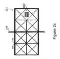
- FIGS. 2 a , 2 b , and 2 care schematic plan views of a diaphragm of the microphone of FIGS. 1 a and 1 b incorporating a diffraction apparatus comprising a diffraction grating, interdigitated fingers, and slits, respectively;
- FIGS. 3 a , 3 b and 3 care calculated reflected diffraction patterns using scalar far-field diffraction formulation for gap values of ⁇ /2, ⁇ /4, and ⁇ /8, respectively;
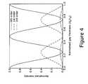
- FIG. 4is a plot of normalized intensity vs. gap for the microphone of FIG. 1 ;
- FIG. 5is a plot of calculated minimum detectable displacement of the diaphragm of the microphone of FIG. 1 as a function of total optical power incident on the photodetectors;
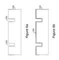
- FIGS. 6 a - 6 dare a fabrication process flow showing a set of possible fabrication steps useful for forming the microphone of FIGS. 1 a and 1 b;
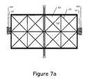
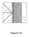
- FIGS. 7 a and 7 bare a front side optical and a rear side SEM view of the diaphragm of the microphone of FIGS. 1 a and 1 b ;
- the present inventionis a directional microphone incorporating a diaphragm, movable in response to sound pressure and an optical sensing mechanism for detecting diaphragm displacement.
- the diaphragm of the microphoneis designed to respond to pressure gradients, giving it a first order directional response to incident sound.
- This mechanical structureis integrated with a compact optical sensing mechanism that uses optical interferometry to generate an electrical output signal representative of the sound impinging upon the microphone's diaphragm.
- the novel structureovercomes adverse effects of capacitive sensing of microphones of the prior art.
- One of the main objectives of the present inventionis to provide a differential microphone suitable for use in a hearing aid and which uses optical sensing in cooperation with a micromachined diaphragm.
- optical sensingprovides high electrical sensitivity, which, in combination with high mechanical sensitivity of the microphone membrane, results in a small minimum detectable sound pressure level.
- FIGS. 1 a and 1 bthere are shown schematic, side, cross-sectional and schematic, perspective views, respectively, of a microphone assembly incorporating an optical interferometer in accordance with the present invention, generally at reference number 100 .
- a diaphragm 102 having stiffeners 104 disposed upon a rear surface 106 thereofis free to “rock” (i.e., rotate) about a hinge 108 in response to sound pressure (shown schematically as arrow 110 ) impinging thereupon.
- a diffraction mechanism 120is operatively connected to diaphragm 102 . Diffraction mechanism 120 may be implemented in a variety of ways. As shown in FIGS.
- diffraction mechanism 120is a diffraction grating 120 a ( FIG. 2 a ), typically disposed centrally in diaphragm 102 close to its edge where deflection is large.
- a reflective diffraction grating 120 a having a period of approximately 1 ⁇ mhas been found suitable for use in the application. It will be recognized, however, that a laser operating at a different wavelength may require a different periodicity in a diffraction grating.
- the diffraction gratingcan be curved to implement a diffractive lens to steer and focus the reflected beam to obtain a desired light pattern on the photodetector plane.
- slits 120 cmay be disposed in diaphragm 102 to provide the required diffraction function.
- interdigitated fingers 120 bFIG. 2 b
- An embodiment using interdigitated fingersis described in detail hereinbelow. It will be recognized that other means for implementing diffraction mechanism 120 may exist and the invention is, therefore, not considered limited to the devices chosen used for purposes of disclosure. Rather the invention contemplates any and all suitable diffraction mechanisms.
- the term diffraction mechanismis used to refer to any diffraction device suitable for use in practicing the instant invention.
- a protective screen 112is disposed intermediate a sound source 110 and a front face of diaphragm 102 .
- Screen 112is isolated therefrom by a layer 136 , typically formed from silicon dioxide or the like.
- protective screen 112consists of a micromachined silicon plate that contains a plurality of very small holes, slits, or other orifices 114 sized to exclude airborne particulate contamination (e.g., dust) from diaphragm 102 and other interior regions, not shown, of microphone 100 .
- the small holes 114allow the passage of sound pressure 110 .
- a lower surface of protective screen 112bears an electrically conductive (typically metallic) layer 118 used to apply a voltage dependent force (i.e., a mechanical bias) to diaphragm 102 as described in detail hereinbelow.
- a voltage dependent forcei.e., a mechanical bias
- Conductive layer 118in addition to helping provide a voltage dependent force, also provides an optically reflective surface that enables the detection of interference fringes between the reflected light from the diffraction mechanism 120 (e.g., optical grating 120 a , etc.) incorporated on/into diaphragm 102 and screen 112 disposed forward of diaphragm 102 .
- Screen 112must be as stiff as possible so that the reflective surface of conductive layer 118 is mechanically stable with respect to movements of diaphragm 102 .
- the reflective rear surface of conductive layer 118forms a fixed mirror portion of the optical interferometer.
- Screen 112is integrally attached to diaphragm 102 and manufactured as part of the micromachining process used to form microphone 100 . The micromachining process is described in detail hereinbelow.
- a miniature vertical cavity surface emitting laser (VCSEL) 122is disposed behind diaphragm 102 , typically on or in a bottom chip 140 .
- Bottom chip 140is typically attached to the remainder of microphone 100 by a bonding layer 138 .
- Coherent light 132 from VCSEL 122is directed toward diffraction mechanism 120 .
- a Model VCT-F85-A32 VCSEL supplied by Lasermate Corp. operating at a wavelength of approximately 0.85 ⁇ m with an aperture of approximately 9 ⁇ mhas been found suitable for the application. It will be recognized, however, that other similar coherent light sources provided by other vendors may be suitable for the application. Consequently, the invention is not limited to a particular model or operating wavelength but includes any suitable coherent light source operating at any wavelength.
- An array of photodetectors 124is also disposed behind diaphragm 102 .
- a linear array of three photodetectors 124appropriately spaced to capture the zeroth and first orders of refracted light as described hereinbelow.
- VCSEL 122can be tilted with respect to the plane of the photodetectors so that the reflected diffraction orders are efficiently captured by the array of photodetectors 124 .
- the miniature laser and the array of photodetectorscan be formed on the same substrate, such as a gallium arsenide semiconductor material.
- FIG. 1implements a Michelson interferometer complete in a small volume.
- Such a compact arrangement including a low power laser and detection electronicsis suitable for use in hearing aids and other miniature devices requiring a microphone.
- the diffraction grating 120 a or other diffraction apparatus 120 on the microphone diaphragm 102 and the reflective surface of metallic coating 118 on the protective screen 112together form a phase-sensitive diffraction grating.
- Such structuresare used to detect displacements as small as 2 ⁇ 10 ⁇ 4 ⁇ / ⁇ Hz in atomic force microscope (AFM), micromachined accelerometer, and acoustic transducer applications.
- AFMatomic force microscope
- micromachined accelerometermicromachined accelerometer
- acoustic transducer applicationsare used to detect displacements as small as 2 ⁇ 10 ⁇ 4 ⁇ / ⁇ Hz.
- lightreflects both from the diffraction mechanism 120 (e.g., diffraction grating 120 a ) that is integrated into diaphragm 102 and from coating 118 of protective screen 112 , reference numbers 128 , 130 , respectively. While reflected light 128 , 130 is shown schematically as rays, it will be recognized that the reflected diffraction orders have a beam shape of finite effective size determined by the light distribution at the laser source, the shape and curvature of the diffraction mechanism 120 , and the distance traveled by the light 128 , 130 . In the ideal case of a linear grating with 50% fill factor, i.e. equal amount of light reflection from the diffraction mechanism and the coating of the protective screen the reflected light 128 , 130 has odd diffraction orders in addition to the normal specular reflection.
- the reflected light 128 , 130has odd diffraction orders in addition to the normal specular reflection.
- interdigitated fingers 120 b( FIG. 2 b ) bearing reflective rear surfaces may be used to form both the fixed and movable mirrors necessary to form the optical interferometer.
- the use of the fixed interdigitated fingers as the stationary mirrorallows the elimination of a reflective surface on screen 112 .
- Reflective rear surfaces on the movable fingersform the movable mirror.
- Interdigitated fingersare described in detail in copending U.S. patent application Ser. No. 11/198,370.
- Interdigitated fingers 120 bare typically disposed at the end of diaphragm 102 to maximize the relative motion of the fingers relative to associated fixed fingers. It will be recognized, however, that the interdigitated fingers may be disposed at other locations around the perimeter of diaphragm 102 .
- interdigitated fingersIn embodiments utilizing interdigitated fingers, fingers of approximately 100 ⁇ m length and 1 ⁇ m width having approximately 4 ⁇ m periodicity have been found suitable for the application. While the aforementioned dimensions have been determined by detailed finite element analysis, other interdigitated geometries, of course, may be used. Interdigitated fingers may be disposed at one or both ends of diaphragm 102 where deflection thereof is greatest. In alternate embodiments, one or more groups of interdigitated fingers may be disposed at any position on the perimeter of diaphragm 102 .
- FIGS. 3 a , 3 b , and 3 cthere are shown calculated reflected diffraction patterns for various gap values at the surface of the silicon wafer, which carries the photodetectors and associated CMOS electronics, not shown.
- FIGS. 3 a , 3 b , and 3 crepresent gap spacing of ⁇ /2, ⁇ /4, and ⁇ /8, respectively. These calculations are performed using scalar diffraction theory with 1 ⁇ m periodicity.
- the intensities, I 0 and I 1can be expressed as a function of the gap thickness, d 0 128 ( FIG. 1 ), between the microphone diaphragm 102 and the protective screen 112 ( FIG. 1 ) and may be computed as:
- the inventive structureprovides the sensitivity of a Michelson interferometer for small displacements of the microphone diaphragm with the following advantages:
- the microphone diaphragm 102( FIG. 1 ) need only be moved ⁇ 0 /4 to maximize the microphone sensitivity.
- the grating periodis comparable to the wavelength ⁇ 0
- a more accurate calculation of the diffraction patternsshould be performed taking the vectorial nature of the light propagation into account.
- W. Lee and F. L. Degertekin“Rigorous Coupled-wave Analysis of Multilayered Grating Structures,” IEEE Journal of Lightwave Technology, 22, pp. 2359-63, 2004, the diffraction order intensity variation with the gap thickness, d 0 128 can be different than the simple relation in Equation 4.
- a bias voltage in the range of approximately 1-2 V applied between the membrane (i.e., diaphragm 102 ) and the protective screen 112is sufficient to accomplish displacements of this magnitude.
- the selective application of such a bias voltagetherefore, overcomes process variations.
- applying bias voltages suitable for hearing aids or other intended applicationsresults in a robust design.
- VCSELsare ideal for low voltage, low power applications because they can be switched on and off, typically using 1-2V pulses with threshold currents in the 1 mA range to reduce average power. VCSELs having threshold currents below 400 ⁇ A are available. The noise performance of VCSELs has also been improving rapidly. This improvement helps make them suitable for sensor applications where high dynamic ranges (e.g., in the 120-130 dBs) are desirable. Furthermore, using the differential detection scheme (between I 1 and I ⁇ 1 , in Equation (5)), the intensity noise is reduced to negligible levels.
- the minimum detectable displacementdetermines the power consumption.
- an input sound pressure referred noise floor of 15 dBA SPLrequires an MDD of 1 ⁇ 10 ⁇ 4 ⁇ / ⁇ Hz.
- FIG. 5shows the MDD as a function of the average laser power with a 1 M ⁇ feedback resistor. Due to the high electrical sensitivity of the optical sensing technique, the displacement noise is dominated by the shot noise. Hence, custom designed CMOS amplifiers with a 1V supply voltage and 5 ⁇ W power consumption may be used without affecting the photodiode-dominated noise floor. Then, the power consumption of the microphone can be estimated from the laser power required for a given displacement noise from the shot noise relation:
- the average laser power required for 1 ⁇ 10 ⁇ 4 ⁇ / ⁇ Hzis an MDD of approximately 20 ⁇ W. Similar 20 values (e.g., 5.5 ⁇ 10 ⁇ 4 ⁇ / ⁇ Hz with 3 ⁇ W optical power) have already been achieved in some AFM applications.
- This average powermay be achieved using the VCSEL in the pulsed mode as described in copending U.S. patent application Ser. No. 11/297,097 filed by Degertekin et al. on Dec. 8, 2005 for “Displacement Sensor”. Assuming 30% wall plug efficiency for the VCSEL, 20 ⁇ W optical power can be obtained with about 80 ⁇ W input power including optical losses.
- FIGS. 6 a - 6 dthere is shown the fabrication process flow for the microphone diaphragm 102 .
- Many waysmay be found to fabricate the microphone of the present invention.
- the following exemplary methodhas been successfully utilized to fabricate the diaphragm 102 membrane and diffraction mechanism 120 .
- the micromachining fabrication techniqueuses deep-trench etching and sidewall deposition to create very lightweight, very stiff membranes with stiffening ribs at optimal locations.
- the fabricationstarts with a deep reactive ion trench etch into the 4-inch test grade silicon wafer 150 forming trenches 152 that act as the molds for the polysilicon stiffeners 104 ( FIGS. 1 a , 1 b ).
- the etching processis followed by a wet oxidation at approximately 1100° C. to grow an approximately one-micron thick thermal oxide layer 154 on the wafer 150 surface and in the trenches 152 as shown in FIG. 6 b.
- oxide layer 154acts as an etch stop for a subsequent back side cavity etching step that removes the bulk of the silicon wafer 150 from the region 156 behind what will be the diaphragm.
- a film of polysilicon 158is next deposited and planerized to form a flat diaphragm surface 102 having stiffeners 104 formed on a rear surface thereof.
- phosphorus-doped polysiliconis deposited at approximately 580° C. and subsequently annealed at 1100° C. in argon gas for approximately 60 minutes. The annealing step reduces intrinsic stress in the film 158 .
- the back cavity region 156is then etched using a deep reactive ion etch and the thermal oxide layer 154 is removed in buffered oxide etch (BOE).
- the final stepis to etch the polysilicon 158 to define the interdigitated fingers 162 and slits 164 that separate the diaphragm 102 from the substrate 150 .
- FIGS. 7 a and 7 bthere are shown front-side optical and back side schematic views, respectively, of the microphone diaphragm and interdigitated fingers formed in accordance with the forgoing fabrication process.
- FIG. 7 ashows the front surface 160 .
- the interdigitated fingers and slits 162 , 164 on each end of the diaphragm 102extend into the polysilicon layer connected to the silicon substrate 150 .
- the microphone diaphragm 102is separated from the substrate with an approximately 2 ⁇ m gap around the edge and the center hinges for acoustical damping and electrical isolation.
- FIG. 7 cshows the details of the interdigitated fingers as dark lines on the left, whereas the stationary fingers 162 extend from the polysilicon layer attached to the substrate on the right.
Landscapes
- Physics & Mathematics (AREA)
- Engineering & Computer Science (AREA)
- Acoustics & Sound (AREA)
- Signal Processing (AREA)
- Electrostatic, Electromagnetic, Magneto- Strictive, And Variable-Resistance Transducers (AREA)
- Micromachines (AREA)
Abstract
Description
where Vbis the bias voltage, A is the area, h is the air gap between the diaphragm and the back plate, and k is the mechanical stiffness of the diaphragm.
where ε is the permittivity of the air in the gap. Diaphragms that have low equivalent mechanical stiffness, k, have low collapse voltages. To avoid collapse, Vb<<Vcollapse.
where Iinis the incident laser intensity and R is the photodetector responsivity. It may be concluded, therefore, that the inventive structure provides the sensitivity of a Michelson interferometer for small displacements of the microphone diaphragm with the following advantages:
- The bulky beam splitter typically required in a Michelson interferometer is eliminated enabling construction of a miniature interferometer.
- Both the reference reflector and moving reflector (grating) are on the same substrate, thereby minimizing spurious mechanical noise.
- The small distance between the grating120 and the protective screen112 (≈5 μm) enables the use of low power, low voltage VCSELs with short (i.e., 100-150 μm) coherence length as light sources for the interferometer.
- The novel interferometer construction enables integration of photodetectors and electronics in small volumes (i.e., ≈1 mm3).
- Hall N. A. and Degertekin F. L.,An Integrated Optical Detection Method for Capacitive Micromachined Ultrasonic Transducers, Proceedings of 2000 IEEE Ultrasonics Symposium, pp. 951-954, 2000.
- Hall N. A. and Degertekin F. L.,An Integrated Optical Interferometric Detection Method for Micromachined Capacitive Acoustic Transducers, Appl. Phys. Lett., 80, pp. 3859-61 2002.
- W. Lee and F. L. Degertekin,Rigorous Coupled-wave Analysis of Multilayered Grating Structures, IEEE Journal of Lightwave Technology,22, pp. 2359-63, 2004
- W. Cui, B. Bicen, N. Hall, S. A. Jones, F. L. Degertekin, and R. N. MilesProceedings of19thIEEE International Conference on Micro Electro Mechanical Systems(MEMS2006), Jan. 22-26, 2006, Istanbul, Turkey. Optical sensing in a directional MEMS microphone inspired by the ears of the parasitoid fly,Ormia ochracea
Claims (20)
Priority Applications (1)
| Application Number | Priority Date | Filing Date | Title |
|---|---|---|---|
| US12/911,449US8503701B2 (en) | 2006-01-19 | 2010-10-25 | Optical sensing in a directional MEMS microphone |
Applications Claiming Priority (2)
| Application Number | Priority Date | Filing Date | Title |
|---|---|---|---|
| US11/335,137US7826629B2 (en) | 2006-01-19 | 2006-01-19 | Optical sensing in a directional MEMS microphone |
| US12/911,449US8503701B2 (en) | 2006-01-19 | 2010-10-25 | Optical sensing in a directional MEMS microphone |
Related Parent Applications (1)
| Application Number | Title | Priority Date | Filing Date |
|---|---|---|---|
| US11/335,137DivisionUS7826629B2 (en) | 2006-01-19 | 2006-01-19 | Optical sensing in a directional MEMS microphone |
Publications (2)
| Publication Number | Publication Date |
|---|---|
| US20110038492A1 US20110038492A1 (en) | 2011-02-17 |
| US8503701B2true US8503701B2 (en) | 2013-08-06 |
Family
ID=38263211
Family Applications (2)
| Application Number | Title | Priority Date | Filing Date |
|---|---|---|---|
| US11/335,137Expired - Fee RelatedUS7826629B2 (en) | 2006-01-19 | 2006-01-19 | Optical sensing in a directional MEMS microphone |
| US12/911,449Active2026-07-21US8503701B2 (en) | 2006-01-19 | 2010-10-25 | Optical sensing in a directional MEMS microphone |
Family Applications Before (1)
| Application Number | Title | Priority Date | Filing Date |
|---|---|---|---|
| US11/335,137Expired - Fee RelatedUS7826629B2 (en) | 2006-01-19 | 2006-01-19 | Optical sensing in a directional MEMS microphone |
Country Status (2)
| Country | Link |
|---|---|
| US (2) | US7826629B2 (en) |
| WO (1) | WO2007084653A2 (en) |
Cited By (30)
| Publication number | Priority date | Publication date | Assignee | Title |
|---|---|---|---|---|
| US20150323456A1 (en)* | 2014-05-09 | 2015-11-12 | Apple Inc. | Tilted mems |
| US9479875B2 (en) | 2015-01-23 | 2016-10-25 | Silicon Audio Directional, Llc | Multi-mode microphones |
| US9503820B2 (en) | 2015-01-23 | 2016-11-22 | Silicon Audio Directional, Llc | Multi-mode microphones |
| US9510074B2 (en) | 2014-07-07 | 2016-11-29 | Apple Inc. | Grating only optical microphone |
| US9510110B2 (en) | 2014-07-07 | 2016-11-29 | Apple Inc. | Open top back plate optical microphone |
| US9554213B2 (en) | 2012-10-01 | 2017-01-24 | The Research Foundation For The State University Of New York | Hinged MEMS diaphragm |
| US9564146B2 (en) | 2014-08-01 | 2017-02-07 | Bongiovi Acoustics Llc | System and method for digital signal processing in deep diving environment |
| US9615189B2 (en) | 2014-08-08 | 2017-04-04 | Bongiovi Acoustics Llc | Artificial ear apparatus and associated methods for generating a head related audio transfer function |
| US9615813B2 (en) | 2014-04-16 | 2017-04-11 | Bongiovi Acoustics Llc. | Device for wide-band auscultation |
| US9621994B1 (en) | 2015-11-16 | 2017-04-11 | Bongiovi Acoustics Llc | Surface acoustic transducer |
| US9638672B2 (en)* | 2015-03-06 | 2017-05-02 | Bongiovi Acoustics Llc | System and method for acquiring acoustic information from a resonating body |
| US9741355B2 (en) | 2013-06-12 | 2017-08-22 | Bongiovi Acoustics Llc | System and method for narrow bandwidth digital signal processing |
| US9793872B2 (en) | 2006-02-07 | 2017-10-17 | Bongiovi Acoustics Llc | System and method for digital signal processing |
| US9883318B2 (en) | 2013-06-12 | 2018-01-30 | Bongiovi Acoustics Llc | System and method for stereo field enhancement in two-channel audio systems |
| US9906867B2 (en) | 2015-11-16 | 2018-02-27 | Bongiovi Acoustics Llc | Surface acoustic transducer |
| US9906858B2 (en) | 2013-10-22 | 2018-02-27 | Bongiovi Acoustics Llc | System and method for digital signal processing |
| US10069471B2 (en) | 2006-02-07 | 2018-09-04 | Bongiovi Acoustics Llc | System and method for digital signal processing |
| US10158337B2 (en) | 2004-08-10 | 2018-12-18 | Bongiovi Acoustics Llc | System and method for digital signal processing |
| CN109565635A (en)* | 2016-07-11 | 2019-04-02 | 美商楼氏电子有限公司 | Split signal differential mems microphone |
| US10639000B2 (en) | 2014-04-16 | 2020-05-05 | Bongiovi Acoustics Llc | Device for wide-band auscultation |
| US10701505B2 (en) | 2006-02-07 | 2020-06-30 | Bongiovi Acoustics Llc. | System, method, and apparatus for generating and digitally processing a head related audio transfer function |
| US10820883B2 (en) | 2014-04-16 | 2020-11-03 | Bongiovi Acoustics Llc | Noise reduction assembly for auscultation of a body |
| US10848118B2 (en) | 2004-08-10 | 2020-11-24 | Bongiovi Acoustics Llc | System and method for digital signal processing |
| US10848867B2 (en) | 2006-02-07 | 2020-11-24 | Bongiovi Acoustics Llc | System and method for digital signal processing |
| US10959035B2 (en) | 2018-08-02 | 2021-03-23 | Bongiovi Acoustics Llc | System, method, and apparatus for generating and digitally processing a head related audio transfer function |
| US11202161B2 (en) | 2006-02-07 | 2021-12-14 | Bongiovi Acoustics Llc | System, method, and apparatus for generating and digitally processing a head related audio transfer function |
| US11211043B2 (en) | 2018-04-11 | 2021-12-28 | Bongiovi Acoustics Llc | Audio enhanced hearing protection system |
| US20220240023A1 (en)* | 2019-05-22 | 2022-07-28 | Ams International Ag | Optical transducer and method for measuring displacement |
| US11431312B2 (en) | 2004-08-10 | 2022-08-30 | Bongiovi Acoustics Llc | System and method for digital signal processing |
| US12091313B2 (en) | 2019-08-26 | 2024-09-17 | The Research Foundation For The State University Of New York | Electrodynamically levitated actuator |
Families Citing this family (59)
| Publication number | Priority date | Publication date | Assignee | Title |
|---|---|---|---|---|
| US7440117B2 (en)* | 2002-03-29 | 2008-10-21 | Georgia Tech Research Corp. | Highly-sensitive displacement-measuring optical device |
| US7355720B1 (en)* | 2005-12-20 | 2008-04-08 | Sandia Corporation | Optical displacement sensor |
| GB0605576D0 (en)* | 2006-03-20 | 2006-04-26 | Oligon Ltd | MEMS device |
| TWI367034B (en)* | 2008-08-01 | 2012-06-21 | Ind Tech Res Inst | Structure of a speaker unit |
| DE102007046769A1 (en)* | 2007-09-29 | 2009-04-16 | Leuze Electronic Gmbh + Co. Kg | sensor arrangement |
| CN102150439B (en)* | 2008-09-12 | 2015-04-22 | 楼氏电子亚洲有限公司 | Transducer system apparatus and method |
| TWI376964B (en)* | 2008-09-12 | 2012-11-11 | Ind Tech Res Inst | Speaker device |
| US8205497B1 (en) | 2009-03-05 | 2012-06-26 | Sandia Corporation | Microelectromechanical inertial sensor |
| US8280080B2 (en)* | 2009-04-28 | 2012-10-02 | Avago Technologies Wireless Ip (Singapore) Pte. Ltd. | Microcap acoustic transducer device |
| DE102009026629B4 (en)* | 2009-06-02 | 2017-09-21 | Robert Bosch Gmbh | Micromechanical system with a buried thin structured polysilicon layer and method for its production |
| US20110235156A1 (en)* | 2010-03-26 | 2011-09-29 | Qualcomm Mems Technologies, Inc. | Methods and devices for pressure detection |
| EP2420470B1 (en)* | 2010-08-18 | 2015-10-14 | Nxp B.V. | MEMS Microphone |
| US8594507B2 (en) | 2011-06-16 | 2013-11-26 | Honeywell International Inc. | Method and apparatus for measuring gas concentrations |
| US20120321322A1 (en)* | 2011-06-16 | 2012-12-20 | Honeywell International Inc. | Optical microphone |
| JP5232334B1 (en)* | 2011-08-25 | 2013-07-10 | パナソニック株式会社 | Optical microphone |
| ITMI20111579A1 (en)* | 2011-09-02 | 2013-03-03 | Saati Spa | MEMS MICROPHONE WITH INTEGRATED TEXTILE PROTECTION SCREEN. |
| US9239386B2 (en) | 2011-10-05 | 2016-01-19 | Infineon Technologies Ag | Sonic sensors and packages |
| WO2013061578A1 (en)* | 2011-10-24 | 2013-05-02 | パナソニック株式会社 | Optical microphone |
| US8783106B1 (en) | 2011-12-13 | 2014-07-22 | Sandia Corporation | Micromachined force-balance feedback accelerometer with optical displacement detection |
| CN102543064A (en)* | 2011-12-31 | 2012-07-04 | 中国科学院半导体研究所 | Laser doppler interference based voice detecting system |
| CN102543065B (en)* | 2011-12-31 | 2013-11-20 | 中国科学院半导体研究所 | Laser doppler interference based voice detecting system |
| US9409763B2 (en)* | 2012-04-04 | 2016-08-09 | Infineon Technologies Ag | MEMS device and method of making a MEMS device |
| US9285390B2 (en) | 2012-06-06 | 2016-03-15 | Northrop Grumman Systems Corporation | Optical accelerometer system |
| WO2014031380A1 (en) | 2012-08-21 | 2014-02-27 | Board Of Regents, The University Of Texas System | Acoustic sensor |
| US9510121B2 (en)* | 2012-12-06 | 2016-11-29 | Agency For Science, Technology And Research | Transducer and method of controlling the same |
| NO20130884A1 (en)* | 2013-06-21 | 2014-12-22 | Sinvent As | Optical offset sensor element |
| KR101478970B1 (en) | 2013-07-08 | 2015-01-05 | 한국기술교육대학교 산학협력단 | Microphone for estimating sound direction |
| US9510107B2 (en)* | 2014-03-06 | 2016-11-29 | Infineon Technologies Ag | Double diaphragm MEMS microphone without a backplate element |
| US20160150327A1 (en)* | 2014-11-25 | 2016-05-26 | Knowles Electronics, Llc | Photosensitive Microphone |
| CN107211218B (en) | 2014-11-28 | 2021-05-18 | 奥德拉声学公司 | High displacement acoustic transducer system |
| US10034109B2 (en)* | 2015-04-09 | 2018-07-24 | Audera Acoustics Inc. | Acoustic transducer systems with position sensing |
| GB201506046D0 (en) | 2015-04-09 | 2015-05-27 | Sinvent As | Speech recognition |
| CN106403821A (en)* | 2015-07-27 | 2017-02-15 | 中国科学院苏州纳米技术与纳米仿生研究所 | Displacement sensor, usage and manufacturing method thereof and interferometer |
| CN105490142B (en)* | 2015-12-17 | 2018-07-03 | 中国人民解放军国防科学技术大学 | A kind of laser acoustic method and device |
| US9992581B2 (en) | 2016-03-25 | 2018-06-05 | Northrop Grumman Systems Corporation | Optical microphone system |
| US9973860B2 (en)* | 2016-04-05 | 2018-05-15 | Infineon Technologies Ag | System and method for an optical MEMS transducer |
| US10573291B2 (en) | 2016-12-09 | 2020-02-25 | The Research Foundation For The State University Of New York | Acoustic metamaterial |
| GB2558963A (en) | 2017-01-18 | 2018-07-25 | Cirrus Logic Int Semiconductor Ltd | Flexible membrane |
| US9967664B1 (en)* | 2017-05-22 | 2018-05-08 | Apple Inc. | Sensor assembly for measuring diaphragm displacement and temperature in a micro speaker |
| WO2019103206A1 (en)* | 2017-11-24 | 2019-05-31 | 주식회사 파트론 | Directional microphone |
| CN112334867A (en) | 2018-05-24 | 2021-02-05 | 纽约州立大学研究基金会 | Capacitive sensor |
| EP3628990B1 (en)* | 2018-09-26 | 2021-08-25 | ams International AG | Integrated optical transducer and method for detecting dynamic pressure changes |
| EP3629598A1 (en)* | 2018-09-26 | 2020-04-01 | ams AG | Integrated optical transducer and method for fabricating an integrated optical transducer |
| CN112913261A (en) | 2018-10-23 | 2021-06-04 | ams有限公司 | Sensor with corrugated diaphragm |
| GB201904005D0 (en)* | 2019-03-22 | 2019-05-08 | Sensibel As | Microphone housing |
| US11079230B2 (en) | 2019-05-10 | 2021-08-03 | Northrop Grumman Systems Corporation | Fiber-optic gyroscope (FOG) assembly |
| CN110388980A (en)* | 2019-07-31 | 2019-10-29 | 山东大学 | A Micro Acoustic Sensor Based on Diffraction Grating Structure |
| CN210513399U (en)* | 2019-08-22 | 2020-05-12 | 歌尔科技有限公司 | A vibration sensing device |
| CN112449295A (en)* | 2019-08-30 | 2021-03-05 | 华为技术有限公司 | Microphone chip, microphone and terminal equipment |
| EP3885311B1 (en) | 2020-03-27 | 2024-05-01 | ams International AG | Apparatus for sound detection, sound localization and beam forming and method of producing such apparatus |
| CN111654794B (en)* | 2020-05-19 | 2021-05-18 | 歌尔智能科技有限公司 | MEMS microphone signal processing method and device and MEMS microphone |
| CN111579817B (en)* | 2020-06-03 | 2021-03-16 | 武汉理工大学 | Fiber Bragg Grating 2D Accelerometer Based on Multi-hinge and Its Manufacturing Process |
| US20240098410A1 (en)* | 2021-02-15 | 2024-03-21 | Ams Sensors Singapore Pte. Ltd. | Electro-acoustic transducer |
| DE112022000757T5 (en)* | 2021-03-31 | 2023-11-09 | Ams International Ag | DISPLACEMENT DETECTOR, ARRAY OF DISPLACEMENT DETECTORS AND METHOD FOR MAKING A DISPLACEMENT DETECTOR |
| WO2022212607A1 (en)* | 2021-03-31 | 2022-10-06 | Ams International Ag | Displacement detector, array of displacement detectors and method of manufacturing a displacement detector |
| CN113905299B (en)* | 2021-10-11 | 2024-09-24 | 维沃移动通信有限公司 | Microphone structure and electronic equipment |
| WO2024160666A1 (en) | 2023-01-31 | 2024-08-08 | Tdk Electronics Ag | Optical mems microphone and method of manufacturing an optical mems microphone |
| WO2025008395A1 (en)* | 2023-07-04 | 2025-01-09 | Ams-Osram International Gmbh | Optical microphone and method of fabricating an optical microphone |
| CN117202064B (en)* | 2023-09-22 | 2024-05-10 | 郑州大学 | Optical microphone and sound transmission system based on diamond microcantilever |
Citations (6)
| Publication number | Priority date | Publication date | Assignee | Title |
|---|---|---|---|---|
| US4403144A (en)* | 1978-07-26 | 1983-09-06 | Rockwell International Corporation | Fiber optic accelerometer |
| US5359445A (en)* | 1987-10-30 | 1994-10-25 | Alliedsignal Inc. | Fiber optic sensor |
| US20020039463A1 (en)* | 2000-06-28 | 2002-04-04 | Degertekin Fahrettin Levent | Optical displacement sensor |
| US20040130728A1 (en)* | 2002-03-29 | 2004-07-08 | Degertekin Fahrettin Levent | Highly-sensitive displacement-measuring optical device |
| US6788796B1 (en) | 2001-08-01 | 2004-09-07 | The Research Foundation Of The State University Of New York | Differential microphone |
| US20050052724A1 (en)* | 2003-07-25 | 2005-03-10 | Kabushiki Kaisha Toshiba | Opto-acoustoelectric device and methods for analyzing mechanical vibration and sound |
Family Cites Families (7)
| Publication number | Priority date | Publication date | Assignee | Title |
|---|---|---|---|---|
| US5311360A (en)* | 1992-04-28 | 1994-05-10 | The Board Of Trustees Of The Leland Stanford, Junior University | Method and apparatus for modulating a light beam |
| EP1239698A4 (en)* | 1999-12-13 | 2006-11-22 | Kenwood Corp | Optical acoustoelectric transducer |
| US20020118850A1 (en)* | 2000-08-02 | 2002-08-29 | Yeh Jer-Liang (Andrew) | Micromachine directional microphone and associated method |
| US7876924B1 (en)* | 2003-10-20 | 2011-01-25 | The Research Foundation Of State University Of New York | Robust diaphragm for an acoustic device |
| US7936894B2 (en)* | 2004-12-23 | 2011-05-03 | Motorola Mobility, Inc. | Multielement microphone |
| US7545945B2 (en) | 2005-08-05 | 2009-06-09 | The Research Foundation Of The State University Of New York | Comb sense microphone |
| US7355720B1 (en)* | 2005-12-20 | 2008-04-08 | Sandia Corporation | Optical displacement sensor |
- 2006
- 2006-01-19USUS11/335,137patent/US7826629B2/ennot_activeExpired - Fee Related
- 2007
- 2007-01-18WOPCT/US2007/001406patent/WO2007084653A2/enactiveApplication Filing
- 2010
- 2010-10-25USUS12/911,449patent/US8503701B2/enactiveActive
Patent Citations (7)
| Publication number | Priority date | Publication date | Assignee | Title |
|---|---|---|---|---|
| US4403144A (en)* | 1978-07-26 | 1983-09-06 | Rockwell International Corporation | Fiber optic accelerometer |
| US5359445A (en)* | 1987-10-30 | 1994-10-25 | Alliedsignal Inc. | Fiber optic sensor |
| US20020039463A1 (en)* | 2000-06-28 | 2002-04-04 | Degertekin Fahrettin Levent | Optical displacement sensor |
| US6567572B2 (en) | 2000-06-28 | 2003-05-20 | The Board Of Trustees Of The Leland Stanford Junior University | Optical displacement sensor |
| US6788796B1 (en) | 2001-08-01 | 2004-09-07 | The Research Foundation Of The State University Of New York | Differential microphone |
| US20040130728A1 (en)* | 2002-03-29 | 2004-07-08 | Degertekin Fahrettin Levent | Highly-sensitive displacement-measuring optical device |
| US20050052724A1 (en)* | 2003-07-25 | 2005-03-10 | Kabushiki Kaisha Toshiba | Opto-acoustoelectric device and methods for analyzing mechanical vibration and sound |
Non-Patent Citations (7)
| Title |
|---|
| Cui, W. et al., "Optical Sensing in a Directional MEMS Microphone Inspired by the Ears of the Parasitoid Fly, Ormia Ochracea", Jan. 2006. |
| Hall N. and Degertekin F.L., "An Integrated Optical Detection Method for Capacitive Micromachined Ultrasonic Transducers," Proceedings of 2000 IEEE Ultrasonics Symposium, pp. 951-954, 2000. |
| Hall N.A. and Degertekin F.L., "An Integrated Optical Interferometric Detection Method for Micromachined Capacitive Acoustic Transducers," Appl. Phys. Lett., 80, pp. 3859-3861 2002. |
| Lee and F.L. Degertekin, "Rigorous Coupled-wave Analysis of Multilayered Grating Structures," IEEE Journal of Lightwave Technology, 22, pp. 2359-2363, 2004. |
| U.S. Appl. No. 10/689,189, Miles. |
| U.S. Appl. No. 10/704,932, Degertekin. |
| U.S. Appl. No. 11/198,370, Miles. |
Cited By (46)
| Publication number | Priority date | Publication date | Assignee | Title |
|---|---|---|---|---|
| US10848118B2 (en) | 2004-08-10 | 2020-11-24 | Bongiovi Acoustics Llc | System and method for digital signal processing |
| US11431312B2 (en) | 2004-08-10 | 2022-08-30 | Bongiovi Acoustics Llc | System and method for digital signal processing |
| US10158337B2 (en) | 2004-08-10 | 2018-12-18 | Bongiovi Acoustics Llc | System and method for digital signal processing |
| US10666216B2 (en) | 2004-08-10 | 2020-05-26 | Bongiovi Acoustics Llc | System and method for digital signal processing |
| US9793872B2 (en) | 2006-02-07 | 2017-10-17 | Bongiovi Acoustics Llc | System and method for digital signal processing |
| US10291195B2 (en) | 2006-02-07 | 2019-05-14 | Bongiovi Acoustics Llc | System and method for digital signal processing |
| US11425499B2 (en) | 2006-02-07 | 2022-08-23 | Bongiovi Acoustics Llc | System and method for digital signal processing |
| US10069471B2 (en) | 2006-02-07 | 2018-09-04 | Bongiovi Acoustics Llc | System and method for digital signal processing |
| US10848867B2 (en) | 2006-02-07 | 2020-11-24 | Bongiovi Acoustics Llc | System and method for digital signal processing |
| US11202161B2 (en) | 2006-02-07 | 2021-12-14 | Bongiovi Acoustics Llc | System, method, and apparatus for generating and digitally processing a head related audio transfer function |
| US10701505B2 (en) | 2006-02-07 | 2020-06-30 | Bongiovi Acoustics Llc. | System, method, and apparatus for generating and digitally processing a head related audio transfer function |
| US9554213B2 (en) | 2012-10-01 | 2017-01-24 | The Research Foundation For The State University Of New York | Hinged MEMS diaphragm |
| US9906869B2 (en) | 2012-10-01 | 2018-02-27 | The Research Foundation For The State University Of New York | Hinged MEMS diaphragm, and method of manufacture thereof |
| US10412533B2 (en) | 2013-06-12 | 2019-09-10 | Bongiovi Acoustics Llc | System and method for stereo field enhancement in two-channel audio systems |
| US9741355B2 (en) | 2013-06-12 | 2017-08-22 | Bongiovi Acoustics Llc | System and method for narrow bandwidth digital signal processing |
| US9883318B2 (en) | 2013-06-12 | 2018-01-30 | Bongiovi Acoustics Llc | System and method for stereo field enhancement in two-channel audio systems |
| US10999695B2 (en) | 2013-06-12 | 2021-05-04 | Bongiovi Acoustics Llc | System and method for stereo field enhancement in two channel audio systems |
| US11418881B2 (en) | 2013-10-22 | 2022-08-16 | Bongiovi Acoustics Llc | System and method for digital signal processing |
| US10313791B2 (en) | 2013-10-22 | 2019-06-04 | Bongiovi Acoustics Llc | System and method for digital signal processing |
| US9906858B2 (en) | 2013-10-22 | 2018-02-27 | Bongiovi Acoustics Llc | System and method for digital signal processing |
| US10917722B2 (en) | 2013-10-22 | 2021-02-09 | Bongiovi Acoustics, Llc | System and method for digital signal processing |
| US9615813B2 (en) | 2014-04-16 | 2017-04-11 | Bongiovi Acoustics Llc. | Device for wide-band auscultation |
| US10820883B2 (en) | 2014-04-16 | 2020-11-03 | Bongiovi Acoustics Llc | Noise reduction assembly for auscultation of a body |
| US11284854B2 (en) | 2014-04-16 | 2022-03-29 | Bongiovi Acoustics Llc | Noise reduction assembly for auscultation of a body |
| US10639000B2 (en) | 2014-04-16 | 2020-05-05 | Bongiovi Acoustics Llc | Device for wide-band auscultation |
| US9404860B2 (en)* | 2014-05-09 | 2016-08-02 | Apple Inc. | Micro-electro-mechanical system optical sensor with tilt plates |
| US20160337762A1 (en)* | 2014-05-09 | 2016-11-17 | Apple Inc. | Tilted mems |
| US9609439B2 (en)* | 2014-05-09 | 2017-03-28 | Apple Inc. | Method of detecting sound using a micro-electro-mechanical system optical microphone |
| US20150323456A1 (en)* | 2014-05-09 | 2015-11-12 | Apple Inc. | Tilted mems |
| US9510110B2 (en) | 2014-07-07 | 2016-11-29 | Apple Inc. | Open top back plate optical microphone |
| US9510074B2 (en) | 2014-07-07 | 2016-11-29 | Apple Inc. | Grating only optical microphone |
| US9564146B2 (en) | 2014-08-01 | 2017-02-07 | Bongiovi Acoustics Llc | System and method for digital signal processing in deep diving environment |
| US9615189B2 (en) | 2014-08-08 | 2017-04-04 | Bongiovi Acoustics Llc | Artificial ear apparatus and associated methods for generating a head related audio transfer function |
| US9479875B2 (en) | 2015-01-23 | 2016-10-25 | Silicon Audio Directional, Llc | Multi-mode microphones |
| US9503820B2 (en) | 2015-01-23 | 2016-11-22 | Silicon Audio Directional, Llc | Multi-mode microphones |
| US9638672B2 (en)* | 2015-03-06 | 2017-05-02 | Bongiovi Acoustics Llc | System and method for acquiring acoustic information from a resonating body |
| US9998832B2 (en) | 2015-11-16 | 2018-06-12 | Bongiovi Acoustics Llc | Surface acoustic transducer |
| US9906867B2 (en) | 2015-11-16 | 2018-02-27 | Bongiovi Acoustics Llc | Surface acoustic transducer |
| US9621994B1 (en) | 2015-11-16 | 2017-04-11 | Bongiovi Acoustics Llc | Surface acoustic transducer |
| CN109565635B (en)* | 2016-07-11 | 2020-12-04 | 美商楼氏电子有限公司 | Split-Signal Differential MEMS Microphone |
| CN109565635A (en)* | 2016-07-11 | 2019-04-02 | 美商楼氏电子有限公司 | Split signal differential mems microphone |
| US11211043B2 (en) | 2018-04-11 | 2021-12-28 | Bongiovi Acoustics Llc | Audio enhanced hearing protection system |
| US10959035B2 (en) | 2018-08-02 | 2021-03-23 | Bongiovi Acoustics Llc | System, method, and apparatus for generating and digitally processing a head related audio transfer function |
| US20220240023A1 (en)* | 2019-05-22 | 2022-07-28 | Ams International Ag | Optical transducer and method for measuring displacement |
| US11979714B2 (en)* | 2019-05-22 | 2024-05-07 | Ams International Ag | Optical transducer and method for measuring displacement |
| US12091313B2 (en) | 2019-08-26 | 2024-09-17 | The Research Foundation For The State University Of New York | Electrodynamically levitated actuator |
Also Published As
| Publication number | Publication date |
|---|---|
| WO2007084653A3 (en) | 2008-06-05 |
| US20110038492A1 (en) | 2011-02-17 |
| US20070165896A1 (en) | 2007-07-19 |
| US7826629B2 (en) | 2010-11-02 |
| WO2007084653A2 (en) | 2007-07-26 |
Similar Documents
| Publication | Publication Date | Title |
|---|---|---|
| US8503701B2 (en) | Optical sensing in a directional MEMS microphone | |
| US6567572B2 (en) | Optical displacement sensor | |
| US7518737B2 (en) | Displacement-measuring optical device with orifice | |
| US7355723B2 (en) | Apparatus comprising a high-signal-to-noise displacement sensor and method therefore | |
| US7440117B2 (en) | Highly-sensitive displacement-measuring optical device | |
| US7583390B2 (en) | Accelerometer comprising an optically resonant cavity | |
| US7428054B2 (en) | Micro-optical sensor system for pressure, acceleration, and pressure gradient measurements | |
| US9479875B2 (en) | Multi-mode microphones | |
| Lee et al. | Fabrication and characterization of a micromachined acoustic sensor with integrated optical readout | |
| US7116430B2 (en) | Highly-sensitive displacement-measuring optical device | |
| US9503820B2 (en) | Multi-mode microphones | |
| Cui et al. | Optical sensing inadirectional memsmicrophone inspired by the ears of the parasitoid fly, Ormia ochracea | |
| JP7387645B2 (en) | optical microphone assembly | |
| US7894618B2 (en) | Apparatus comprising a directionality-enhanced acoustic sensor | |
| US7796267B2 (en) | System, method and apparatus for a micromachined interferometer using optical splitting | |
| US20160219375A1 (en) | Multi-mode Microphones | |
| US8154734B2 (en) | Optical interferometric sensor | |
| Bicen et al. | Integrated optical displacement detection and electrostatic actuation for directional optical microphones with micromachined biomimetic diaphragms | |
| Sagberg et al. | Optical microphone based on a modulated diffractive lens | |
| US8508745B2 (en) | System, method and apparatus for a micromachined interferometer using optical splitting | |
| Hall et al. | Surface and bulk-silicon-micromachined optical displacement sensor fabricated with the SwIFT-Lite™ process | |
| CN114175683B (en) | Optical transducer and method for measuring displacement | |
| Okandan et al. | Optical microphone structures fabricated for broad bandwidth and low noise | |
| Hall et al. | Self-calibrating micromachined microphones with integrated optical displacement detection | |
| Lee | Diffraction-based integrated optical readout for micromachined optomechanical sensors |
Legal Events
| Date | Code | Title | Description |
|---|---|---|---|
| AS | Assignment | Owner name:RESEARCH FOUNDATION OF STATE UNIVERSITY OF NEW YOR Free format text:ASSIGNMENT OF ASSIGNORS INTEREST;ASSIGNOR:MILES, RONALD N.;REEL/FRAME:025419/0465 Effective date:20101115 Owner name:GEORGIA TECH RESEARCH CORPORATION, GEORGIA Free format text:ASSIGNMENT OF ASSIGNORS INTEREST;ASSIGNOR:DEGERTEKIN, F. LEVENT;REEL/FRAME:025419/0668 Effective date:20101123 | |
| STCF | Information on status: patent grant | Free format text:PATENTED CASE | |
| AS | Assignment | Owner name:NATIONAL INSTITUTES OF HEALTH (NIH), U.S. DEPT. OF Free format text:CONFIRMATORY LICENSE;ASSIGNOR:THE RESEARCH FOUNDATION FOR THE STATE UNIVERSITY OF NEW YORK;REEL/FRAME:030993/0877 Effective date:20130807 | |
| AS | Assignment | Owner name:THE RESEARCH FOUNDATION FOR THE STATE UNIVERSITY OF NEW YORK, NEW YORK Free format text:CHANGE OF NAME;ASSIGNOR:THE RESEARCH FOUNDATION OF STATE UNIVERSITY OF NEW YORK;REEL/FRAME:031896/0589 Effective date:20120619 Owner name:THE RESEARCH FOUNDATION FOR THE STATE UNIVERSITY O Free format text:CHANGE OF NAME;ASSIGNOR:THE RESEARCH FOUNDATION OF STATE UNIVERSITY OF NEW YORK;REEL/FRAME:031896/0589 Effective date:20120619 | |
| FPAY | Fee payment | Year of fee payment:4 | |
| AS | Assignment | Owner name:NATIONAL INSTITUTES OF HEALTH (NIH), U.S. DEPT. OF Free format text:CONFIRMATORY LICENSE;ASSIGNOR:STATE UNIVERSITY OF NY,BINGHAMTON;REEL/FRAME:043687/0035 Effective date:20170825 | |
| MAFP | Maintenance fee payment | Free format text:PAYMENT OF MAINTENANCE FEE, 8TH YR, SMALL ENTITY (ORIGINAL EVENT CODE: M2552); ENTITY STATUS OF PATENT OWNER: SMALL ENTITY Year of fee payment:8 | |
| MAFP | Maintenance fee payment | Free format text:PAYMENT OF MAINTENANCE FEE, 12TH YR, SMALL ENTITY (ORIGINAL EVENT CODE: M2553); ENTITY STATUS OF PATENT OWNER: SMALL ENTITY Year of fee payment:12 |