US8502454B2 - Solid state semiconductor LED replacement for fluorescent lamps - Google Patents
Solid state semiconductor LED replacement for fluorescent lampsDownload PDFInfo
- Publication number
- US8502454B2 US8502454B2US12/367,539US36753909AUS8502454B2US 8502454 B2US8502454 B2US 8502454B2US 36753909 AUS36753909 AUS 36753909AUS 8502454 B2US8502454 B2US 8502454B2
- Authority
- US
- United States
- Prior art keywords
- fluorescent
- fluorescent lamp
- ballast
- voltage
- rectifier
- Prior art date
- Legal status (The legal status is an assumption and is not a legal conclusion. Google has not performed a legal analysis and makes no representation as to the accuracy of the status listed.)
- Active - Reinstated, expires
Links
Images


Classifications
- H—ELECTRICITY
- H05—ELECTRIC TECHNIQUES NOT OTHERWISE PROVIDED FOR
- H05B—ELECTRIC HEATING; ELECTRIC LIGHT SOURCES NOT OTHERWISE PROVIDED FOR; CIRCUIT ARRANGEMENTS FOR ELECTRIC LIGHT SOURCES, IN GENERAL
- H05B31/00—Electric arc lamps
- H05B31/48—Electric arc lamps having more than two electrodes
- H05B31/50—Electric arc lamps having more than two electrodes specially adapted for AC
- H—ELECTRICITY
- H05—ELECTRIC TECHNIQUES NOT OTHERWISE PROVIDED FOR
- H05B—ELECTRIC HEATING; ELECTRIC LIGHT SOURCES NOT OTHERWISE PROVIDED FOR; CIRCUIT ARRANGEMENTS FOR ELECTRIC LIGHT SOURCES, IN GENERAL
- H05B45/00—Circuit arrangements for operating light-emitting diodes [LED]
- H05B45/30—Driver circuits
- H05B45/357—Driver circuits specially adapted for retrofit LED light sources
- H05B45/3578—Emulating the electrical or functional characteristics of discharge lamps
- H—ELECTRICITY
- H05—ELECTRIC TECHNIQUES NOT OTHERWISE PROVIDED FOR
- H05B—ELECTRIC HEATING; ELECTRIC LIGHT SOURCES NOT OTHERWISE PROVIDED FOR; CIRCUIT ARRANGEMENTS FOR ELECTRIC LIGHT SOURCES, IN GENERAL
- H05B45/00—Circuit arrangements for operating light-emitting diodes [LED]
- H05B45/30—Driver circuits
- H05B45/37—Converter circuits
- H05B45/3725—Switched mode power supply [SMPS]
- H—ELECTRICITY
- H05—ELECTRIC TECHNIQUES NOT OTHERWISE PROVIDED FOR
- H05B—ELECTRIC HEATING; ELECTRIC LIGHT SOURCES NOT OTHERWISE PROVIDED FOR; CIRCUIT ARRANGEMENTS FOR ELECTRIC LIGHT SOURCES, IN GENERAL
- H05B45/00—Circuit arrangements for operating light-emitting diodes [LED]
- H05B45/50—Circuit arrangements for operating light-emitting diodes [LED] responsive to malfunctions or undesirable behaviour of LEDs; responsive to LED life; Protective circuits
- F—MECHANICAL ENGINEERING; LIGHTING; HEATING; WEAPONS; BLASTING
- F21—LIGHTING
- F21K—NON-ELECTRIC LIGHT SOURCES USING LUMINESCENCE; LIGHT SOURCES USING ELECTROCHEMILUMINESCENCE; LIGHT SOURCES USING CHARGES OF COMBUSTIBLE MATERIAL; LIGHT SOURCES USING SEMICONDUCTOR DEVICES AS LIGHT-GENERATING ELEMENTS; LIGHT SOURCES NOT OTHERWISE PROVIDED FOR
- F21K9/00—Light sources using semiconductor devices as light-generating elements, e.g. using light-emitting diodes [LED] or lasers
- F21K9/20—Light sources comprising attachment means
- F21K9/27—Retrofit light sources for lighting devices with two fittings for each light source, e.g. for substitution of fluorescent tubes
- H—ELECTRICITY
- H05—ELECTRIC TECHNIQUES NOT OTHERWISE PROVIDED FOR
- H05B—ELECTRIC HEATING; ELECTRIC LIGHT SOURCES NOT OTHERWISE PROVIDED FOR; CIRCUIT ARRANGEMENTS FOR ELECTRIC LIGHT SOURCES, IN GENERAL
- H05B45/00—Circuit arrangements for operating light-emitting diodes [LED]
- H05B45/30—Driver circuits
- H05B45/355—Power factor correction [PFC]; Reactive power compensation
- Y—GENERAL TAGGING OF NEW TECHNOLOGICAL DEVELOPMENTS; GENERAL TAGGING OF CROSS-SECTIONAL TECHNOLOGIES SPANNING OVER SEVERAL SECTIONS OF THE IPC; TECHNICAL SUBJECTS COVERED BY FORMER USPC CROSS-REFERENCE ART COLLECTIONS [XRACs] AND DIGESTS
- Y02—TECHNOLOGIES OR APPLICATIONS FOR MITIGATION OR ADAPTATION AGAINST CLIMATE CHANGE
- Y02B—CLIMATE CHANGE MITIGATION TECHNOLOGIES RELATED TO BUILDINGS, e.g. HOUSING, HOUSE APPLIANCES OR RELATED END-USER APPLICATIONS
- Y02B20/00—Energy efficient lighting technologies, e.g. halogen lamps or gas discharge lamps
- Y02B20/30—Semiconductor lamps, e.g. solid state lamps [SSL] light emitting diodes [LED] or organic LED [OLED]
Definitions
- Fluorescent tube lightingis a significant source of lighting in many applications, particularly in commercial markets, for a number of reasons such as higher efficiency and longer life than incandescent bulbs.
- newer solid semiconductor lightingsuch as light emitting diodes (LEDs) have been developed having advantages over fluorescent tube lighting. Conversion from fluorescent tube lighting to newer technologies can be prohibitively costly due to characteristics that are fundamentally associated with fluorescent lighting.
- fluorescent lights and lampscannot run directly off the alternating current (AC) mains.
- ACalternating current
- a ballast 10is required to be placed between the AC mains 12 and the fluorescent lamp or tube 14 as illustrated in FIG.
- some embodimentsprovide an apparatus for replacing a fluorescent lamp, including an electrical connector adapted to electrically connect to a fluorescent lamp fixture, a DC rectifier connected to the electrical connector, a voltage converter connected to the DC rectifier, and a non-fluorescent light source connected to the voltage converter.
- the DC rectifier, voltage converter and non-fluorescent light sourceare substantially contained within a housing that is physically configured to replace the fluorescent lamp in a fluorescent lamp fixture.
- the non-fluorescent light sourcecomprises at least one LED.
- the apparatusis adapted to connect through the electrical connector to an AC output of a fluorescent ballast in the fluorescent lamp fixture.
- the fluorescent ballastcomprises a magnetic ballast.
- the fluorescent ballastcomprises an electronic ballast.
- the voltage converteris adapted to reduce a voltage from the DC rectifier.
- the apparatusincludes protection circuitry connected between the electrical connector and the DC rectifier in the housing.
- the protection circuitryis adapted to prevent a voltage exceeding a threshold value from passing through the protection circuitry.
- the apparatusincludes startup and feedback circuitry connected to the DC rectifier in the housing.
- the startup and feedback circuitryis adapted to simulate an electrical behavior of a fluorescent tube in response to a startup sequence from a ballast in the fluorescent lamp fixture.
- the apparatusincludes a power factor correction circuit connected to the DC rectifier in the housing.
- the apparatusincludes a cathode heater simulation circuit in the housing and switchably connected to the electrical connector.
- the cathode heater simulation circuitis adapted to simulate a fluorescent tube cathode when a ballast in the fluorescent lamp fixture is in a cathode heating mode.
- the voltage convertercomprises a pulse generator and a constant current driver.
- the apparatusincludes a current overload protection circuit connected to the voltage converter in the housing.
- the apparatusincludes a thermal protection circuit connected to the voltage converter in the housing.
- the thermal protection circuitis adapted to reduce a current to the non-fluorescent light source in inverse proportion to a temperature of the apparatus.
- the apparatusincludes a dimming circuit connected to the voltage converter in the housing.
- the dimming circuitis adapted to controllably reduce a current to the non-fluorescent light source.
- inventionsprovide a method of powering an LED replacement tube in a fluorescent lamp fixture.
- the methodincludes receiving an AC voltage input from the fluorescent lamp fixture, and converting the AC voltage to a power source for at least one LED in the LED replacement tube.
- the convertingis performed by a power converter in the LED replacement tube.
- the methodincludes rectifying the AC voltage to a DC voltage before the converting.
- the methodincludes electrically simulating a fluorescent tube response to a startup sequences from a ballast in the fluorescent lamp fixture. The simulating is performed in the LED replacement tube.
- the methodincludes controlling a power factor of the LED replacement tube resulting in a higher power factor, wherein the controlling is performed in the LED replacement tube.
- the methodincludes dimming the at least one LED by reducing a current to the at least one LED in the LED replacement tube, wherein the dimming is performed in the LED replacement tube.
- the apparatusincludes an electrical connector adapted to electrically connect to an AC output of a fluorescent ballast in the fluorescent lamp fixture.
- the apparatusalso includes a cathode heater simulation circuit switchably connected to the electrical connector.
- the cathode heater simulation circuitis adapted to simulate a fluorescent tube cathode when a ballast in the fluorescent lamp fixture is in a cathode heating mode.
- the apparatusalso includes a protection circuit connected to the electrical connector.
- the protection circuitis adapted to prevent a voltage exceeding a threshold value from passing through the protection circuit.
- the apparatusalso includes a DC rectifier connected to the protection circuit, a power factor correction circuit connected to the DC rectifier.
- the apparatusalso includes a startup and feedback circuit connected to the DC rectifier.
- the startup and feedback circuitis adapted to simulate an electrical behavior of a fluorescent tube in response to a startup sequence from a ballast in the fluorescent lamp fixture.
- the apparatusalso includes a voltage converter connected to the DC rectifier and adapted to reduce a voltage from the DC rectifier.
- the apparatusalso includes a current overload protection circuit connected to the voltage converter.
- the apparatusalso includes a thermal protection circuit connected to the voltage converter. The thermal protection circuit is adapted to reduce a current from the voltage converter in inverse proportion to a temperature of the apparatus.
- the apparatusalso includes a dimming circuit connected to the voltage converter. The dimming circuit is adapted to controllably reduce a current from the voltage converter.
- the apparatusalso includes at least one LED connected to the voltage converter.
- the apparatusalso includes a housing substantially containing the cathode heater simulation circuit, DC rectifier, power factor correction circuit, startup and feedback circuit, voltage converter, current overload protection circuit, thermal protection circuit, dimming circuit and at least one LED.
- the housingis physically configured to replace the fluorescent lamp in the fluorescent lamp fixture.
- FIG. 1depicts a prior art fluorescent lamp fixture.
- FIG. 2depicts a fluorescent lamp fixture with a solid state semiconductor LED replacement for a fluorescent lamp with a single ended power converter in accordance with some embodiments.
- FIG. 3depicts a fluorescent lamp fixture with a solid state semiconductor LED replacement for a fluorescent lamp with a double ended power converter in accordance with some embodiments.
- FIG. 4depicts a fluorescent lamp fixture with a solid state semiconductor LED replacement for a fluorescent lamp with multi-directional LED orientation in accordance with some embodiments.
- FIG. 5depicts a block diagram of a power converter in accordance with some embodiments.
- FIG. 6depicts a block diagram of a power converter for use with a magnetic ballast in accordance with some embodiments.
- FIG. 7depicts a block diagram of a power converter with power factor correction circuitry in accordance with some embodiments.
- FIG. 8depicts a block diagram of a power converter with power factor correction circuitry in accordance with some embodiments.
- FIG. 9depicts a block diagram of a power converter for use with an electronic ballast in accordance with some embodiments.
- FIG. 10depicts a block diagram of a power converter with protection and ballast handling circuitry in accordance with some embodiments.
- FIG. 11depicts a block diagram of a power converter for use without a fluorescent ballast in accordance with some embodiments.
- FIG. 12depicts a block diagram of a power converter for use without a fluorescent ballast and including current overload and thermal protection in accordance with some embodiments.
- FIG. 13depicts a block diagram of a power converter with current overload and thermal protection circuitry in accordance with some embodiments.
- FIG. 14depicts a block diagram of a power converter in accordance with some embodiments.
- FIG. 15depicts a block diagram of a power converter operating in an AC mode in accordance with some embodiments.
- FIG. 16is a flow chart of an exemplary operation for powering an LED replacement tube in a fluorescent lamp fixture.
- FIG. 2disclose various embodiments of a solid state semiconductor LED replacement for fluorescent lamps.
- a fluorescent lamp fixtureincludes an AC input 12 powering a ballast 10 .
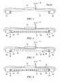
- An LED replacement tube 22is inserted into the fluorescent lamp fixture in place of a fluorescent tube.
- the LED replacement tube 22includes one or more electrical connectors 24 extending from the housing 26 of the LED replacement tube 22 to connect to the fluorescent tube connectors 20 in the fixture.
- the LED replacement tube 22includes one or more non-fluorescent light sources, such as LEDs 30 , that are electrically connected to a power converter 32 , for example on a printed circuit board 34 or other electrically connective support structure.
- the light sources in the LED replacement tube 22can be any non-fluorescent light source, including LEDs and organic light emitting diodes (OLEDs).
- LEDhas been used generically throughout this document, including in the claims, to refer to any light source other than a fluorescent light source, including LEDs and OLEDs.
- the power converter 32in various embodiments is adapted to draw power from the ballast 10 or from the AC mains 12 in the absence of a ballast 10 or given a non-functional ballast 10 , and to convert the power from the ballast 10 or AC mains 12 for use by the LEDs 30 . In other embodiments as illustrated in FIG.
- multiple power converters 32 and 36may be included, connecting in the fluorescent lamp fixture at both ends of the LED replacement tube 22 .
- Any desired number and orientation of LEDs 30may be included.
- the LEDs 30may be oriented to direct light substantially downward across an angle such as 180 degrees, or may be oriented across wider angles as illustrated in FIG. 4 to more closely resemble the light output of a fluorescent tube, thereby reflecting off a reflector 40 above the LED replacement tube 22 in the fluorescent lamp fixture.
- the LED replacement tube 22 disclosed hereinprovides a high efficiency long life lamp replacement that is more environmentally friendly than fluorescent tubes.
- the LED replacement tube 22may be used in place of fluorescent or neon tubes and is form function compatible with existing lamp fixtures and ballasts, both of the magnetic and electrical types of operation over a wide voltage range of operation offering high efficiency, high power factor and long life with environmentally friendly materials.
- the LED replacement tube 22makes use of the standard tubular, spiral, or any other standard form factor lamp and ballast and related fixtures to allow an LED light source in a variety of shapes, sizes, colors, arrays, etc. to be used and inserted into existing and new fluorescent lamp fixtures of any length and any power, voltage and current combination.
- the housing 26consists of a tube that can be made of any suitable material including glass and/or plastic.
- the housing 26may have other shapes and sizes and may include a mixture of different materials, such as an opaque plastic upper portion and a substantially transparent plastic or glass lower portion.
- a partially open housing 26such as an exposed support structure, e.g., a printed circuit board, with LEDs 30 mounted thereon and exposed to the air without covering.
- the LED replacement tube 22may use any suitable type, number and configuration of LEDs 30 such as, for example, ultraviolet LEDs with a phosphor coating on the LEDs or on the housing 26 itself to produce suitable output light in the desired wavelength regions (i.e., white or visible light), or may use any number and combination of different colored LEDs to accomplish the desired illumination performance.
- the LED or LED array 30is contained within the housing 26 and may have any shape or form including but not limited to circular, cylindrical, triangular, rectangular, square, string, helical, spiral, polygonal, perpendicular, etc.
- the power converter 32is also contained within the housing 26 to convert the input alternating current (AC) voltage/current/power into the appropriate DC output required for the LED or LED arrays 30 to operate.
- the power converter 32may supply an AC output of suitable voltage and frequency to drive LEDs connected in parallel and inverse fashion, that is, a parallel array of LEDs arranged anode to cathode and cathode to anode.
- the LED replacement tube 22may include various types of interfaces that permit both wired and wireless communications with the power converter 32 to permit monitoring, control, dimming, turn on, turn off, light sensor input, various sensor input, human input, automated and automated control system input etc., Bluetooth, web/internet-based, WIMAX, WIFI, telephone, cellular phone and all other types and standards for communications, etc.
- the support circuitrymay be contained either entirely within the LED replacement tube 22 , may be located outside the housing 26 , or partially inside and partially outside.
- the power converter 32may be adapted to operate with the existing ballast in place in the light fixture, or with the ballast removed and bypassed in the fixture.
- the LEDs 30may be directed in any desired manner, such as a unidirectional orientation to illuminate in one direction from the LED replacement tube 22 as illustrated in FIGS. 2 and 3 , or may be configured to illuminate substantially in all directions, or in any other custom spotlight fashion (e.g., FIG. 4 ). Reflectors may also be included within the LED replacement tube 22 to produce the desired output.
- ballasts 10typically fall within one of two broad categories, magnetic and electric.
- Magnetic ballastsin general are older and less efficient ballasts that typically include an inductive coil and a starter circuit. Magnetic ballasts are also prone to failure after a certain number of years. In addition to being inefficient, magnetic ballasts also present poor electrical characteristics to the AC mains which can be viewed in terms of having a poor power factor.
- the output of a magnetic ballastshould be an ideal sine wave usually at the same frequency as the AC mains (in general 50 to 60 hertz), however, the discussion and application discussed here is fully applicable to higher frequency (i.e., 400 Hz) magnetic ballasts.
- This sine wavecan have the same or similar amplitude as the AC mains or the sine wave can have a higher amplitude than the AC mains.
- magnetic ballaststypically have amplitudes similar to the AC mains which, depending on the type and diameter of the fluorescent tube, can range from around 100 VAC RMS up to over 400 VAC RMS with 120, 240 and 277 VAC RMS being commonly used in the United States.
- Electronic ballastsare newer and more modern ways to efficiently light fluorescent lamps. Whereas magnetic ballasts tend to be very similar in their performance and operation and in general lack “smarts” or electronic intelligence, electrical ballasts have been designed and implemented in a wider variety from very simple to very complicated versions.
- Electronic ballastsinclude versions that have built in microprocessors and/or microcontrollers and other such electronic state machines capable of executing simple to complex timing sequences that are often required to best optimize factors such as the efficiency and lifetime of the fluorescent lamp based on the intrinsic and fundamental physics of the gas discharge and plasma physics and processes that govern fluorescent lamps. These electronic ballasts can be designed to provide excellent power factor correction and can be made to be very efficient in terms of electrical power usage and consumption.
- electronic ballastscan also be used to make decisions as to the condition and health of the fluorescent tube and even make a decision as to whether the fluorescent tube is no longer functional (i.e., burned out) or even present (i.e., installed). These types of decisions are typically based on electronic and electrical information fed back to the ballast during and after the electronic ballast is or is in the process of applying voltages, energy and power to the fluorescent lamp. Based on the sequence and responses to these voltages, the ballast is often designed to decide if the fluorescent lamp is behaving properly and in a normal mode such that a plasma discharge has been struck in the lamp and appropriate current is flowing through the fluorescent lamp(s).
- the ballastmay continue repeating the turn on sequence or may effectively shut down until commanded, typically by human intervention, to retry and restart the startup sequence.
- the output frequency and voltagecan range from around 30 kHz (i.e., above the human audio range) to upwards of 100 kHz and even higher, again depending on the ballast design and intended application.
- the output voltagesalso in general bear no direct relationship to the input AC mains voltages, but instead are typically chosen based on the type of fluorescent lamp (with the diameter and length of the lamp being major considerations).
- the use of “smart” electronicsallows the possibility of huge and sometimes subtle variations in the start-up sequence that the ballast presents to the fluorescent lamp including how and when (i.e., the timing sequence and method of applying voltage to the fluorescent lamp) the ballast responds to the information fed back to the ballast from the lamp, it is important that the lamp behave in most every way in a manner that would be expected from a fluorescent lamp/light source.
- Fluorescent lampsalso have heaters (which are also commonly referred to as filaments or cathodes) at each end of the lamp. How these heaters/filaments/cathodes are used and the associated timing sequence can have a dramatic effect on the life of the fluorescent tube and, in some cases, the life of the ballast as well.
- preheat startpower is first applied to the cathodes typically from less than one second to at most a few seconds before attempting to breakdown the gas in the fluorescent tube and strike a plasma.
- instant startno power is applied to the cathodes or power is applied at the same time as the high voltage is applied and this high voltage is applied across the fluorescent tube to strike a plasma with or without the assistance of electrons created at the cathodes.
- the cathodesWith rapid start, the cathodes are always heated resulting in a fast rapid start at the expense of “wasted energy” when the fluorescent lamp is not on (i.e., not lit for producing light).
- the voltages that electronic ballasts put outcan typically range from hundreds of volts up to one thousand volts or more depending on the ballast design and intended fluorescent tube type(s) (i.e., T12, T9, T8, T5, etc.) that the ballast is intended to drive, operate, support, etc.
- a common type of electronic ballast designuses a multi frequency or sweeping frequency resonance approach to breakdown the gas and strike a plasma in the fluorescent tube.
- the open circuit voltage of such a resonant approachcan be quite high (in the thousands of volts) depending on a number of factors including the quality factor (Q) of the circuit.
- fluorescent light sourcesrequire AC voltages containing as little as possible direct current (DC) voltages whereas, in general, LED and OLED light sources require primarily DC voltages and are potentially damaged by large AC voltages that swing in the negative direction (which reverse biases the LED and produces no light output) unless the LEDs or LEDs are arranged in a back to back configuration (i.e., for example, two LEDs are put in parallel with the cathode of the first LED attached to the anode of the second LED, and the anode of the first LED attached to cathode of the second LED).
- DCdirect current
- the LED replacement tube 22 used with an existing ballast 10mimics both the behavior of a fluorescent tube lamp and also is adapted to survive the potentially high voltages associated with fluorescent lamps and ballasts.
- LED replacement tube 22may include:
- Circuitryto identify and handle instant on, rapid on and pre-heat sequences.
- LEDsincluding but not limited to red, green, blue LEDs and/or any other possible combination of LEDs and colors.
- Circuitry to handle AC voltages up to and above 1 kV in amplitude and 100 KHz in frequencyCircuitry to handle AC voltages up to and above 1 kV in amplitude and 100 KHz in frequency.
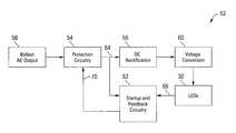
- An AC output 50 from a ballast 10supplies power to a conversion circuit 52 within the LED replacement tube 22 .
- the AC output 50 from a ballast 10may have a frequency of 30 kHz up to 100 kHz or even higher, with a voltage of about 150 VAC up to 1000 VAC peak or more depending on the fluorescent tube and cathode being used.
- the conversion circuit 52includes protection circuitry 54 that protects other components of the conversion circuit 52 and LEDs 30 from being damaged by high voltage/current/frequencies from the ballast 10 when it is turned on.
- the protection circuitry 54may lower the voltage, or may harmlessly discharge the voltage if it exceeds a threshold value so that it cannot damage other components of the conversion circuit 52 .
- the protection circuitry 54may include a spark gap connected in parallel with the connections from the AC output 50 , shorting across the AC output 50 to discharge the voltage to prevent damage to the conversion circuit 52 .
- the protection circuitry 54may include a switchably connected load that is applied when the voltage rises above a threshold value, loading down the ballast 10 and reducing the voltage, then being disconnected when the voltage falls to avoid triggering fault detection in the ballast 10 .
- the protection circuitry 54may also include a feedback controlled switch to connect or disconnect power from the AC output 50 to other elements of the conversion circuit 52 .
- a DC rectifier 56is connected to the protection circuitry 54 to convert the AC power from the AC output 50 to DC power for use by the LEDs 30 .
- the DC rectifier 56may be a high voltage rectifier, for example a 1 kV or 1.2 kV (or higher voltage) diode bridge of four or more diodes.
- a voltage converter 60such as a boost/buck or buck converter is connected to the DC rectifier 56 to reduce the voltage from the voltage converter 60 , for example dropping the voltage down to 48 VDC or 12 VDC or to whatever voltage is suitable for the LEDs 30 connected to the voltage converter 60 .
- the voltage rangecould be from roughly around 3 volts DC to greater than 100 volts DC.
- Startup and feedback circuitry 62 in the conversion circuit 52processes feedback signals 64 and 66 , particularly during the startup sequence, and provides control signals 70 to the protection circuitry 54 .
- the startup and feedback circuitry 62controls the protection circuitry 54 to protect the DC rectifier 56 and voltage converter 60 by applying a load resistor in the protection circuitry 54 to limit the voltage from the ballast 10 , or to control a switch to connect the DC rectifier 56 to the protection circuitry 54 , etc.
- the startup and feedback circuitry 62is adapted to meet the needs of the ballast 10 so that it appears that a functional fluorescent tube is in place, as well as controlling the protection circuitry 54 to protect the conversion circuit 52 from damaging voltages, currents or frequencies.
- an embodiment of a conversion circuit 80is disclosed for use in an LED replacement tube 22 for a fluorescent lamp fixture having a magnetic ballast 10 .
- the magnetic ballast 10supplies an AC voltage 82 .
- Protection circuitry 84is connected to the AC voltage 82 and provides voltage, current and/or frequency protection to the conversion circuit 80 from the magnetic ballast 10 , as controlled by control signals 86 from startup and feedback circuitry 90 .
- a magnetic ballastincludes a starter that can supply high voltages during startup, a magnetic ballast tends to operate at a lower voltage than an electronic ballast.
- the magnetic ballasttypically does not include complex error sensing circuitry that would require particular fluorescent tube simulation behaviors from the LED replacement tube 22 .
- the operating frequency of the magnetic ballastis also much closer to that of the AC mains, reducing or eliminating a need for frequency compensation.
- the protection circuitry 84thus may use lower voltage and slower components if desired than the protection circuitry 54 of FIG. 5 .
- a DC rectifier 92is connected to the protection circuitry 84 to produce a DC voltage, and a current controller 94 generates a constant DC current for use by the LEDs 30 .
- the current controller 94may use any suitable circuit for generating a constant current.
- the startup and feedback circuitry 90processes feedback from the output of the protection circuitry 84 and the LEDs 30 , and as with the protection circuitry 84 , may use simpler and less robust components than with an electronic ballast.
- the startup and feedback circuitry 90in one embodiment may be as simple as a voltage divider and comparator to cause the protection circuitry 84 to disconnect from the DC rectifier 92 or to connect a resistor across the ballast 10 as a current limiter, particularly during startup or when the voltage otherwise rises.
- Simple startup circuitscan be applied depending on the characteristics of the ballast 10 and, in some cases, the start-up circuit may not be needed or may not be activated. This can also be true due to the choice of components in the LED replacement tube 22 that are rated to survive the highest voltage produced by the ballast 10 .
- FIG. 7another embodiment of a conversion circuit 100 is powered by the AC output 82 of a magnetic ballast 10 , with protection circuitry 84 controlled by startup and feedback circuitry 90 as in FIG. 6 .
- power factor correction circuitry 102is connected between the protection circuitry 84 and DC rectifier 92 .
- the power factor correction circuitry 102compensates for the notoriously bad power factor of a magnetic ballast 10 .
- the power factor correction circuitry 102also functions if the magnetic ballast 10 is disconnected.
- the power factor correctionmay be performed before DC rectification as well, as in the conversion circuit 104 illustrated in FIG. 8 .
- the power factor correction circuitry 102is connected to the output of the protection circuitry 84
- the DC rectifier 92is connected to the output of the protection circuitry 84 .
- the startup and feedback circuitry 90 in this embodimentoperates on the output of the DC rectifier 92 and the LEDs 30 to control the protection circuitry 84 .
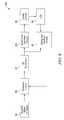
- the conversion circuit 120is powered by the AC output 122 of the electronic ballast 10 .
- Protection and cathode heater circuitry 124is connected to the AC output 122 to simulate a cathode heater for the electronic ballast 10 .
- the protection and cathode heater circuitry 124presents a load such as a resistor that is typical of a cathode in the fluorescent tube being replaced. This load may be disconnected after the startup sequence for efficiency.
- Any suitable circuitrymay be used in the protection and cathode heater circuitry 124 to connect and disconnect the cathode simulation load, such as an RC time constant or a timer circuit.
- Protective circuitry in the protection and cathode heater circuitry 124also protects the conversion circuit 120 from excessive voltage using a device such as a spark gap or a load applied when the voltage exceeds a threshold value or to effectively perform such a function.
- a high frequency DC rectifier 126is connected to the protection and cathode heater circuitry 124 to convert the high frequency AC input to a DC voltage.
- the high frequency DC rectifier 126uses, for example, ultrafast diodes to pass current from the very high frequencies from the electronic ballast 10 .
- a voltage converter 130is connected to the high frequency DC rectifier 126 to provide the proper DC voltage to the LEDs 30 .
- Startup and feedback circuitry 132 connected to the output of the protection and cathode heater circuitry 124 and the LEDs 30may also include high speed electronics to be able to react to the high frequency waveform from the protection and cathode heater circuitry 124 .
- a conversion circuit 140for use in an LED replacement tube 22 for a fluorescent lamp fixture having a magnetic or electronic ballast 10 , in which a pulse generator 142 is used to control a current through the LEDs 30 .
- the conversion circuit 140is powered by an AC output 144 from the ballast 10 .
- Protection and ballast handling circuitry 146is connected to the AC output 144 as with previous embodiments, based on the type of ballast 10 .
- a DC rectifier 150is connected to the protection and ballast handling circuitry 146 to produce a DC voltage.
- the pulse generator 142provides pulsed power from the DC rectifier 150 to control a constant current driver 152 in a switching power supply technique.
- the constant current driver 152supplies a constant current to the LEDs 30 .
- Power factor and constant current feedback circuitry 154controls the timing and width of pulses generated by the pulse generator 142 , as well as controlling the protection and ballast handling circuitry 146 as described above.
- a conversion circuit 170for use in an LED replacement tube 22 for a fluorescent lamp fixture in which the ballast 10 has been removed or is otherwise bypassed or nonfunctional.
- the conversion circuit 170is thus typically powered by a low voltage (in the range of less than 100 V to greater than 500 V), low frequency AC mains input 172 .
- a DC rectifier 174converts the AC input 172 to a DC voltage.
- a pulse generator 176controls a constant current driver 180 to power the LEDs 30 .
- Constant current feedback 182is used by the pulse generator 176 to maintain a constant current from the constant current driver 180 .
- the pulse generator 176 , constant current driver 180 and constant current feedback 182may be any suitable switch mode power supply circuit to power the LEDs 30 in the LED replacement tube 22 from a DC rectified AC mains input 172 .
- FIG. 12another embodiment of a conversion circuit 170 is disclosed for use in an LED replacement tube 22 for a fluorescent lamp fixture in which the ballast 10 has been removed or is otherwise bypassed or nonfunctional.
- power factor correctionis included in the constant current feedback 184 to guarantee a good power factor from the pulse generator 176 and constant current driver 180 .
- Current overload and thermal protection circuitry 190is connected between the constant current driver 180 and pulse generator 176 to reduce the width or frequency of the pulses from the pulse generator 176 if the current through the LEDs 30 exceeds a threshold value or if the temperature of the conversion circuit 170 becomes excessive.
- an embodiment of a conversion circuit 200is disclosed for use in an LED replacement tube 22 for a fluorescent lamp fixture having a magnetic or electronic ballast 10 , in which a pulse generator 202 and constant current driver 204 is used to control a current through the LEDs 30 .
- the conversion circuit 200is powered by an AC output 206 from the ballast 10 .
- DC rectification and protection circuitry 210is connected to the AC output 210 to rectify the AC input and to protect the conversion circuit 200 as with previous embodiments, based on the type of ballast 10 .
- the pulse generator 202provides pulsed power from the DC rectification and protection circuitry 210 to control the constant current driver 204 in a switching power supply technique.
- the constant current driver 204supplies a constant current to the LEDs 30 , as controlled by constant current feedback and control circuitry 208 .
- Current overload and thermal protection circuitry 212is connected between the constant current driver 180 and pulse generator 176 to reduce the width or frequency of the pulses from the pulse generator 176 if the current through the LEDs 30 exceeds a threshold value or if the temperature of the conversion circuit 170 becomes excessive.
- Dimming sense and control circuitry 214is included in the conversion circuit 200 to enable dimming of the LEDs 30 .
- the dimming sense and control circuitry 214can dim the LEDs 30 by reducing the width or frequency of the pulses from the pulse generator 176 , or by causing a dimmable electronic ballast 10 to dim the AC output 206 of the ballast 10 .
- the dimming sense and control circuitry 214may be controlled via a number of interfaces as described above, including wired and wireless interfaces, such as a digital addressable lighting interface (DALI), 0 to 10 VDC analog, pulse width modulation (PWM), digital multiplexing (DMX), etc. If the ballast 10 is dimmable, then it can perform the dimming functions itself or the dimming sense and control circuitry 214 may detect that the ballast 10 is attempting to dim, at which point the dimming sense and control circuitry 214 would narrow the pulses to dim the LEDs 30 .
- DALIdigital addressable lighting interface
- PWMpulse width modulation
- DMXdigital multiplexing
- FIG. 14a more detailed block diagram of an embodiment of a conversion circuit 230 is illustrated.
- An AC input 232powers the conversion circuit 230 through a fuse 234 , an electromagnetic interference (EMI) filter 236 , a protection control circuit 240 and a rectifier 242 .
- Circuitry 244 for power factor control, constant current generation, dimming and protection controlis included to perform the functions described above, again with variations depending on the presence and type of ballast 10 .
- a variable pulse generator 246is driven by the control circuitry 244 , and the variable pulse generator 246 controls constant current drive circuitry including a switch 250 such as a power FET, an energy storage device such as an inductor 252 , and diode 254 .
- the switching power supply circuitryoperates by pulling a current from an upper voltage rail 256 through the LEDs 30 and inductor 252 and switch 250 to a lower voltage rail 260 when a pulse from the variable pulse generator 246 is on, powering the LEDs 30 and storing energy in the inductor 252 .
- the switch 250When the pulse is off, the switch 250 is open, the inductor 252 resists the change in current and recirculates current through the diode 254 , the LEDs 30 and inductor 252 .
- a capacitor 262may be connected in parallel with the LEDs 30 to smooth the voltage if desired.
- a current sensing resistor 264provides a feedback signal 266 to the control circuitry 244 .
- the inductor 252may be replaced or augmented with a transformer and appropriate additional components and/or circuits to provide the same functionality in an isolated configuration (one example being in a flyback mode) and also multiple output taps to control different LEDs (i.e., red, green and blue LEDs) or configurations of LEDs (i.e., segments and bank arrangements and configurations).
- a voltage divider 270 and 272may be used to supply a reference voltage to the control circuitry 244 .
- the control circuitry 244may be powered through a resistor 274 from the upper voltage rail 256 .
- the variable pulse generator 246may also be powered from the upper voltage rail 256 through a resistor 276 .
- Control circuitry 244 and variable pulse generator 246operate at different potentials, so control signals from the control circuitry 244 to the variable pulse generator 246 may pass through a level shifter 284 .
- the conversion circuit 230 used in a LED replacement tube 22may be variously embodied with any suitable output driver and control circuitry, and is not limited to the specific examples set forth above.
- the various embodiments of the conversion circuit 300 in an LED replacement tube 22may drive the LEDs 30 in an AC mode with a suitable voltage and frequency for LEDs 30 connected in parallel and inverse fashion, that is, a parallel array of LEDs arranged anode to cathode and cathode to anode.
- Any of the various embodiments, both described herein and otherwise,may be adapted to drive the LEDs 30 in AC mode, whether in the presence of a magnetic or electronic ballast 10 or in the absence of a ballast 10 .
- the conversion circuit 300may be powered by an AC output 302 from a ballast 10 .
- Protection circuitry 304may be connected to the AC output 302 as discussed above to protect the conversion circuit 300 .
- a voltage converter 306may be used to adapt the level and frequency, as desired, from the protection circuitry 304 to power the LEDs 30 .
- Startup and feedback circuitry 310may be used in the conversion circuit 300 to adapt to the ballast 10 , if any, as described above.
- LED replacement tube 22may also include multiple constant current sources if desired to drive, for example, multiple load groups such as banks of different types or colors of LEDs, etc. These embodiments can include any form(s) of parallel/series back to back configurations of the LEDs. In addition, for both AC and DC approaches, the embodiments and implementations can be designed to produce constant current output(s).
- a method for powering an LED replacement tube in a fluorescent lamp fixtureis summarized in the flow chart of FIG. 16 .
- the methodincludes receiving an AC voltage input from the fluorescent lamp fixture (block 400 ), and converting the AC voltage to a power source for at least one LED in the LED replacement tube, wherein the converting is performed by a power converter in the LED replacement tube (block 402 ).
- the methodmay further include rectifying the AC voltage to a DC voltage before the converting, and electrically simulating a fluorescent tube response to a startup sequences from a ballast in the fluorescent lamp fixture.
Landscapes
- Circuit Arrangement For Electric Light Sources In General (AREA)
Abstract
Description
Claims (19)
Priority Applications (2)
| Application Number | Priority Date | Filing Date | Title |
|---|---|---|---|
| US12/367,539US8502454B2 (en) | 2008-02-08 | 2009-02-08 | Solid state semiconductor LED replacement for fluorescent lamps |
| US13/932,495US20130293131A1 (en) | 2008-02-08 | 2013-07-01 | Solid State Semiconductor LED Replacement for Fluorescent Lamps |
Applications Claiming Priority (2)
| Application Number | Priority Date | Filing Date | Title |
|---|---|---|---|
| US2711508P | 2008-02-08 | 2008-02-08 | |
| US12/367,539US8502454B2 (en) | 2008-02-08 | 2009-02-08 | Solid state semiconductor LED replacement for fluorescent lamps |
Related Child Applications (1)
| Application Number | Title | Priority Date | Filing Date |
|---|---|---|---|
| US13/932,495ContinuationUS20130293131A1 (en) | 2008-02-08 | 2013-07-01 | Solid State Semiconductor LED Replacement for Fluorescent Lamps |
Publications (2)
| Publication Number | Publication Date |
|---|---|
| US20100033095A1 US20100033095A1 (en) | 2010-02-11 |
| US8502454B2true US8502454B2 (en) | 2013-08-06 |
Family
ID=41652268
Family Applications (2)
| Application Number | Title | Priority Date | Filing Date |
|---|---|---|---|
| US12/367,539Active - Reinstated2031-01-26US8502454B2 (en) | 2008-02-08 | 2009-02-08 | Solid state semiconductor LED replacement for fluorescent lamps |
| US13/932,495AbandonedUS20130293131A1 (en) | 2008-02-08 | 2013-07-01 | Solid State Semiconductor LED Replacement for Fluorescent Lamps |
Family Applications After (1)
| Application Number | Title | Priority Date | Filing Date |
|---|---|---|---|
| US13/932,495AbandonedUS20130293131A1 (en) | 2008-02-08 | 2013-07-01 | Solid State Semiconductor LED Replacement for Fluorescent Lamps |
Country Status (1)
| Country | Link |
|---|---|
| US (2) | US8502454B2 (en) |
Cited By (19)
| Publication number | Priority date | Publication date | Assignee | Title |
|---|---|---|---|---|
| US20130134875A1 (en)* | 2010-06-28 | 2013-05-30 | Ningbo Huadian Envirotech Co., Ltd. | Light Regulatable Led Illumination Lamp |
| US20140203716A1 (en)* | 2011-08-15 | 2014-07-24 | Koninklijke Philips N.V. | Electronic ballast-compatible lighting driver for light-emitting diode lamp |
| US20140306615A1 (en)* | 2013-04-11 | 2014-10-16 | Hideep Inc. | Led lighting device using ballast |
| WO2015066566A1 (en)* | 2013-10-31 | 2015-05-07 | Innosys, Inc. | Fluorescent lamp replacement led protection |
| US9049765B1 (en)* | 2014-09-04 | 2015-06-02 | Colorado Energy Research Technologies, LLC | Systems and methods for converting alternating current to drive light-emitting diodes |
| US20150195886A1 (en)* | 2012-06-27 | 2015-07-09 | Koninklijke Philips N.V. | Driver circuit between electromagnetic ballast and led |
| WO2016022612A1 (en)* | 2014-08-04 | 2016-02-11 | Innosys, Inc. | Lighting systems |
| US20160156304A1 (en)* | 2014-12-01 | 2016-06-02 | 4CSOLAR, Inc. | Floating solar panel systems |
| US9557044B2 (en) | 2014-10-20 | 2017-01-31 | Energy Focus, Inc. | LED lamp with dual mode operation |
| US9839077B2 (en)* | 2013-02-22 | 2017-12-05 | Hideep Inc. | LED lighting device using ballast |
| US10060610B1 (en)* | 2017-10-04 | 2018-08-28 | The Toro Company | Light with pre-wired electric wire loop |
| US10398004B1 (en)* | 2018-07-06 | 2019-08-27 | Elb Electronics, Inc. | LED fluorescent lamp emulator circuitry |
| US10412803B1 (en)* | 2018-06-15 | 2019-09-10 | Wistron Corporation | Lighting system, control device and control method |
| US10465860B2 (en) | 2017-06-30 | 2019-11-05 | Signlightsled Llc | Multi oriented, power source agnostic replacement for lighting assembly |
| US11204136B2 (en) | 2018-05-01 | 2021-12-21 | Keystone Technologies, LLC | LED light tubes, light boxes including LED light tubes and methods for installation of LED light tubes in light boxes |
| US11754232B2 (en) | 2015-03-10 | 2023-09-12 | Jiaxing Super Lighting Electric Appliance Co., Ltd. | LED lamp and power source module thereof related applications |
| US12078301B2 (en) | 2015-03-10 | 2024-09-03 | Jiaxing Super Lighting Electric Appliance Co., Ltd. | LED lamp and power source module thereof |
| US12104754B2 (en) | 2014-09-28 | 2024-10-01 | Jiaxing Super Lighting Electric Appliance Co., Ltd. | LED tube lamp and a power supply module thereof |
| US12372209B2 (en) | 2014-09-28 | 2025-07-29 | Jiaxing Super Lighting Electric Appliance Co., Ltd | LED tube lamp |
Families Citing this family (128)
| Publication number | Priority date | Publication date | Assignee | Title |
|---|---|---|---|---|
| JP4577525B2 (en)* | 2007-05-31 | 2010-11-10 | 東芝ライテック株式会社 | Lighting device |
| US8118447B2 (en) | 2007-12-20 | 2012-02-21 | Altair Engineering, Inc. | LED lighting apparatus with swivel connection |
| JP2009200146A (en)* | 2008-02-20 | 2009-09-03 | Sharp Corp | Led drive circuit and led illumination apparatus using it |
| US8360599B2 (en) | 2008-05-23 | 2013-01-29 | Ilumisys, Inc. | Electric shock resistant L.E.D. based light |
| US7938562B2 (en) | 2008-10-24 | 2011-05-10 | Altair Engineering, Inc. | Lighting including integral communication apparatus |
| US8214084B2 (en) | 2008-10-24 | 2012-07-03 | Ilumisys, Inc. | Integration of LED lighting with building controls |
| US8653984B2 (en) | 2008-10-24 | 2014-02-18 | Ilumisys, Inc. | Integration of LED lighting control with emergency notification systems |
| US8901823B2 (en) | 2008-10-24 | 2014-12-02 | Ilumisys, Inc. | Light and light sensor |
| US8444292B2 (en) | 2008-10-24 | 2013-05-21 | Ilumisys, Inc. | End cap substitute for LED-based tube replacement light |
| US8324817B2 (en) | 2008-10-24 | 2012-12-04 | Ilumisys, Inc. | Light and light sensor |
| US8358085B2 (en) | 2009-01-13 | 2013-01-22 | Terralux, Inc. | Method and device for remote sensing and control of LED lights |
| US9326346B2 (en) | 2009-01-13 | 2016-04-26 | Terralux, Inc. | Method and device for remote sensing and control of LED lights |
| US8556452B2 (en) | 2009-01-15 | 2013-10-15 | Ilumisys, Inc. | LED lens |
| US8664880B2 (en) | 2009-01-21 | 2014-03-04 | Ilumisys, Inc. | Ballast/line detection circuit for fluorescent replacement lamps |
| US8148907B2 (en)* | 2009-04-11 | 2012-04-03 | Sadwick Laurence P | Dimmable power supply |
| US20100265732A1 (en)* | 2009-04-21 | 2010-10-21 | Zi Hui Liu | Light tube with led light source |
| US8330381B2 (en)* | 2009-05-14 | 2012-12-11 | Ilumisys, Inc. | Electronic circuit for DC conversion of fluorescent lighting ballast |
| US8299695B2 (en)* | 2009-06-02 | 2012-10-30 | Ilumisys, Inc. | Screw-in LED bulb comprising a base having outwardly projecting nodes |
| EP2446715A4 (en) | 2009-06-23 | 2013-09-11 | Ilumisys Inc | LIGHTING DEVICE WITH LEDS AND SWITCHING CURRENT CONTROL SYSTEM |
| CA2781077A1 (en)* | 2009-11-17 | 2012-06-28 | Terralux, Inc. | Led power-supply detection and control |
| US8896207B2 (en)* | 2009-11-19 | 2014-11-25 | ElectraLED Inc. | Fluorescent light fixture assembly with LED lighting element and converter modules |
| US8147091B2 (en)* | 2009-12-22 | 2012-04-03 | Lightel Technologies Inc. | Linear solid-state lighting with shock protection switches |
| US8322878B2 (en)* | 2009-12-22 | 2012-12-04 | Lightel Technologies Inc. | Linear solid-state lighting with a double safety mechanism free of shock hazard |
| JP5437054B2 (en)* | 2009-12-25 | 2014-03-12 | 三菱電機照明株式会社 | LED lamp, LED lighting device, LED lamp lighting apparatus, and LED lighting system |
| US8540401B2 (en) | 2010-03-26 | 2013-09-24 | Ilumisys, Inc. | LED bulb with internal heat dissipating structures |
| CA2794512A1 (en) | 2010-03-26 | 2011-09-29 | David L. Simon | Led light tube with dual sided light distribution |
| CA2792940A1 (en) | 2010-03-26 | 2011-09-19 | Ilumisys, Inc. | Led light with thermoelectric generator |
| TWM396594U (en)* | 2010-04-09 | 2011-01-21 | Ecolighting Inc | Structural improvement for externally-connected type electrical control lamp |
| US8860312B2 (en) | 2010-05-10 | 2014-10-14 | Metrolight Ltd. | Light emitting diodes driven by high intensity discharge ballast |
| US8454193B2 (en) | 2010-07-08 | 2013-06-04 | Ilumisys, Inc. | Independent modules for LED fluorescent light tube replacement |
| CA2803267A1 (en) | 2010-07-12 | 2012-01-19 | Ilumisys, Inc. | Circuit board mount for led light tube |
| US8541957B2 (en)* | 2010-08-09 | 2013-09-24 | Power Integrations, Inc. | Power converter having a feedback circuit for constant loads |
| US8956006B2 (en)* | 2010-08-23 | 2015-02-17 | Energy Focus, Inc. | Elongated LED lamp for replacing a fluorescent lamp |
| GB201015393D0 (en)* | 2010-09-15 | 2010-10-27 | Saf T Glo Ltd | Lighting systems |
| US9596738B2 (en) | 2010-09-16 | 2017-03-14 | Terralux, Inc. | Communication with lighting units over a power bus |
| CA2810026A1 (en) | 2010-09-16 | 2012-03-22 | Terralux, Inc. | Communication with lighting units over a power bus |
| US8668361B2 (en) | 2010-09-22 | 2014-03-11 | Bridgelux, Inc. | LED-based replacement for fluorescent light source |
| US9095023B2 (en) | 2010-10-19 | 2015-07-28 | Koninklijke Philips N.V. | LED retrofit lamp |
| EP2633227B1 (en) | 2010-10-29 | 2018-08-29 | iLumisys, Inc. | Mechanisms for reducing risk of shock during installation of light tube |
| US8773031B2 (en)* | 2010-11-22 | 2014-07-08 | Innosys, Inc. | Dimmable timer-based LED power supply |
| EP2644008A4 (en)* | 2010-11-23 | 2016-01-20 | Bramal Led Inc | Led lamp with variable input power supply |
| US8870415B2 (en) | 2010-12-09 | 2014-10-28 | Ilumisys, Inc. | LED fluorescent tube replacement light with reduced shock hazard |
| CN102006702A (en)* | 2010-12-10 | 2011-04-06 | 阳江市汉能工业有限公司 | Driving device of light-emitting diode (LED) fluorescent tube |
| US20120161666A1 (en)* | 2010-12-22 | 2012-06-28 | Osram Sylvania Inc. | Light emitting diode retrofit system for fluorescent lighting systems |
| CN102006704A (en)* | 2010-12-24 | 2011-04-06 | 上海电机学院 | Light-emitting diode (LED) drive control circuit and lighting device |
| EP2477456B1 (en)* | 2011-01-14 | 2016-04-06 | Ontopx LED GmbH | Drive circuit for light-emitting diode array |
| CN103380658A (en)* | 2011-02-16 | 2013-10-30 | 皇家飞利浦有限公司 | Electromagnetic ballast-compatible lighting driver for light-emitting diode lamp |
| JP2014513859A (en)* | 2011-03-11 | 2014-06-05 | ヌラリス インコーポレイテッド | Method and apparatus for facilitating coupling of light emitting diode-based bulbs to fluorescent lamp fixtures |
| WO2012131573A1 (en) | 2011-03-30 | 2012-10-04 | Koninklijke Philips Electronics N.V. | Interface circuit |
| US8587215B2 (en)* | 2011-05-05 | 2013-11-19 | General Electric Company | Self-dimming OLED lighting system and control method |
| JP5830986B2 (en)* | 2011-07-06 | 2015-12-09 | 株式会社リコー | Lighting control circuit, illumination lamp using the lighting control circuit, and luminaire using the illumination lamp |
| US20130010461A1 (en)* | 2011-07-07 | 2013-01-10 | Starlights, Inc. | Ballast Bypass Harness Assembly For Use With A Light Emitting Diode Fluorescent Tube Replacement Bulb |
| US9072171B2 (en) | 2011-08-24 | 2015-06-30 | Ilumisys, Inc. | Circuit board mount for LED light |
| IN2014CN02654A (en) | 2011-10-20 | 2015-06-26 | Koninkl Philips Nv | |
| US9730294B2 (en) | 2011-11-07 | 2017-08-08 | GE Lighting Solutions, LLC | Lighting device including a drive device configured for dimming light-emitting diodes |
| WO2013090904A1 (en) | 2011-12-16 | 2013-06-20 | Terralux, Inc. | System and methods of applying bleed circuits in led lamps |
| EP2621247B1 (en)* | 2012-01-25 | 2015-09-30 | Dialog Semiconductor GmbH | Dimming method and system for LED lamp assemblies |
| US8987997B2 (en) | 2012-02-17 | 2015-03-24 | Innosys, Inc. | Dimming driver with stealer switch |
| US9184518B2 (en) | 2012-03-02 | 2015-11-10 | Ilumisys, Inc. | Electrical connector header for an LED-based light |
| CN104221472B (en)* | 2012-03-29 | 2017-06-06 | 飞利浦照明控股有限公司 | Adapter circuit for LED to be coupled to ballast |
| KR101382226B1 (en)* | 2012-04-20 | 2014-04-10 | 주식회사 하이딥 | Led lighting device using ballaster for fluorescent lamp |
| DE102012207221A1 (en)* | 2012-04-30 | 2013-10-31 | Osram Gmbh | Retrofit lamp, has drive circuit does not activating two-pole relay such that drive circuit decouple LEDs of circuit device from output when voltage at input of circuit device exceeds predetermined threshold value |
| US8618746B1 (en)* | 2012-06-11 | 2013-12-31 | Great Eagle Lighting Corporation | LED ballast controller device |
| DE102012209781A1 (en)* | 2012-06-12 | 2013-12-24 | Osram Gmbh | DEVICE FOR GENERATING ELECTROMAGNETIC RADIATION AND ELECTRONIC BALLAST |
| US9163794B2 (en) | 2012-07-06 | 2015-10-20 | Ilumisys, Inc. | Power supply assembly for LED-based light tube |
| US9271367B2 (en) | 2012-07-09 | 2016-02-23 | Ilumisys, Inc. | System and method for controlling operation of an LED-based light |
| JP6397406B2 (en)* | 2012-07-11 | 2018-09-26 | フィリップス ライティング ホールディング ビー ヴィ | Drive circuit between fluorescent ballast and LED |
| TWI401991B (en)* | 2012-07-17 | 2013-07-11 | Geometek Applic Engineering Co Ltd | Power transformation apparatus between dc lighting element and ballast |
| US8956019B2 (en) | 2012-08-27 | 2015-02-17 | Ideal Industries, Inc. | Methods and apparatus for grounding an electrical device via a lampholder |
| US8963438B2 (en)* | 2012-08-28 | 2015-02-24 | Micron Technology, Inc. | Self-identifying solid-state transducer modules and associated systems and methods |
| US8723437B1 (en)* | 2012-12-10 | 2014-05-13 | Dialog Semiconductor Inc. | Filter bandwidth adjustment in a multi-loop dimmer control circuit |
| MX352747B (en)* | 2013-01-22 | 2017-12-06 | Bramal Led Inc | Led lamp, and method of driving at least one led string thereof. |
| US9285084B2 (en) | 2013-03-14 | 2016-03-15 | Ilumisys, Inc. | Diffusers for LED-based lights |
| DE102013205189A1 (en)* | 2013-03-25 | 2014-09-25 | The Green Monkeys Holdings, Ltd. | Electronic component and LED light source |
| US9265119B2 (en) | 2013-06-17 | 2016-02-16 | Terralux, Inc. | Systems and methods for providing thermal fold-back to LED lights |
| BR112015012814A2 (en) | 2013-06-27 | 2017-07-11 | Koninklijke Philips Nv | light source |
| US11255497B2 (en) | 2013-07-05 | 2022-02-22 | DMF, Inc. | Adjustable electrical apparatus with hangar bars for installation in a building |
| US11060705B1 (en) | 2013-07-05 | 2021-07-13 | DMF, Inc. | Compact lighting apparatus with AC to DC converter and integrated electrical connector |
| US10551044B2 (en) | 2015-11-16 | 2020-02-04 | DMF, Inc. | Recessed lighting assembly |
| US10591120B2 (en) | 2015-05-29 | 2020-03-17 | DMF, Inc. | Lighting module for recessed lighting systems |
| US10563850B2 (en) | 2015-04-22 | 2020-02-18 | DMF, Inc. | Outer casing for a recessed lighting fixture |
| US9964266B2 (en) | 2013-07-05 | 2018-05-08 | DMF, Inc. | Unified driver and light source assembly for recessed lighting |
| US10139059B2 (en) | 2014-02-18 | 2018-11-27 | DMF, Inc. | Adjustable compact recessed lighting assembly with hangar bars |
| US10753558B2 (en) | 2013-07-05 | 2020-08-25 | DMF, Inc. | Lighting apparatus and methods |
| US11435064B1 (en) | 2013-07-05 | 2022-09-06 | DMF, Inc. | Integrated lighting module |
| WO2015014680A1 (en) | 2013-07-30 | 2015-02-05 | Koninklijke Philips N.V. | Led replacement lamp for safe operation under fault condition |
| DE102013108775A1 (en)* | 2013-08-13 | 2015-02-19 | Joachim Schmelter | Circuit arrangement for an LED tube and LED tube with a circuit arrangement |
| US9267650B2 (en) | 2013-10-09 | 2016-02-23 | Ilumisys, Inc. | Lens for an LED-based light |
| US20150173138A1 (en)* | 2013-12-18 | 2015-06-18 | General Electric Company | A device and sytem for led linear fluorescent tube lamp driver |
| CN106063381A (en) | 2014-01-22 | 2016-10-26 | 伊卢米斯公司 | LED-based light with addressed LEDs |
| GB2522689A (en)* | 2014-02-03 | 2015-08-05 | David John Powell | Power regulation of LED lighting used to replace fluorescent lighting powered by electronic ballasts |
| US9510400B2 (en) | 2014-05-13 | 2016-11-29 | Ilumisys, Inc. | User input systems for an LED-based light |
| US20170105265A1 (en)* | 2014-05-27 | 2017-04-13 | Laurence P. Sadwick | Lighting Systems |
| WO2015200730A1 (en)* | 2014-06-25 | 2015-12-30 | Innosys, Inc. | Circadian rhythm alignment lighting |
| US20160113076A1 (en)* | 2014-10-20 | 2016-04-21 | Energy Focus, Inc. | Led lamp with dual mode operation |
| US10578656B2 (en)* | 2014-10-20 | 2020-03-03 | Ambiq Micro, Inc. | Method and apparatus for monitoring energy consumption |
| CN104470157A (en)* | 2014-12-30 | 2015-03-25 | 深圳市元科摄影器材有限公司 | LED control system based on WIFI |
| WO2016145264A1 (en)* | 2015-03-10 | 2016-09-15 | Innosys, Inc. | Solid state fluorescent lamp and high intensity discharge replacement |
| WO2016169074A1 (en)* | 2015-04-22 | 2016-10-27 | 罗崇斌 | Led lamp for directly replacing instant-start fluorescent tube |
| US9750100B2 (en) | 2015-05-08 | 2017-08-29 | Ilumisys, Inc. | Light emitting diode lamp dimming signal |
| US10161568B2 (en) | 2015-06-01 | 2018-12-25 | Ilumisys, Inc. | LED-based light with canted outer walls |
| WO2017024185A1 (en)* | 2015-08-04 | 2017-02-09 | Innosys, Inc. | Solid State Lighting Systems |
| WO2017049323A1 (en)* | 2015-09-17 | 2017-03-23 | Innosys, Inc. | Solid state lighting systems |
| DE102015218836A1 (en) | 2015-09-30 | 2017-03-30 | Osram Gmbh | Double-capped LED lamp for operation on an electronic ballast for a low-pressure discharge lamp, in particular a fluorescent lamp, and method for operating such a lamp |
| USD851046S1 (en) | 2015-10-05 | 2019-06-11 | DMF, Inc. | Electrical Junction Box |
| WO2017066496A1 (en)* | 2015-10-13 | 2017-04-20 | Innosys, Inc. | Solid state lighting and sensor systems |
| CN105491716B (en)* | 2015-12-29 | 2019-02-15 | 白磊 | Real time fail feeds back LED light Optimizing Control System and real-time feedback method |
| CN105704867B (en)* | 2016-04-26 | 2018-01-12 | 杰华特微电子(杭州)有限公司 | Voltage control circuit, LED drive circuit and its control method |
| CN108811227A (en)* | 2017-05-05 | 2018-11-13 | 国德联科(北京)科技有限公司 | A method of based on technology of Internet of things on-line checking LED street lamp failure |
| WO2018237294A2 (en) | 2017-06-22 | 2018-12-27 | DMF, Inc. | THIN-PROFILE SURFACE MOUNTING LIGHTING DEVICE |
| US10488000B2 (en) | 2017-06-22 | 2019-11-26 | DMF, Inc. | Thin profile surface mount lighting apparatus |
| CN107333354B (en)* | 2017-07-07 | 2020-07-10 | 厦门普为光电科技有限公司 | L ED lamp tube with voltage boosting circuit |
| US11067231B2 (en) | 2017-08-28 | 2021-07-20 | DMF, Inc. | Alternate junction box and arrangement for lighting apparatus |
| CA3087187A1 (en) | 2017-12-27 | 2019-07-04 | DMF, Inc. | Methods and apparatus for adjusting a luminaire |
| CN110324928A (en)* | 2018-03-28 | 2019-10-11 | 通用电气照明解决方案有限公司 | The electrical shock protection circuit and method of LED lamp tube |
| USD877957S1 (en) | 2018-05-24 | 2020-03-10 | DMF Inc. | Light fixture |
| WO2019241198A1 (en) | 2018-06-11 | 2019-12-19 | DMF, Inc. | A polymer housing for a recessed lighting system and methods for using same |
| TWI643526B (en)* | 2018-09-06 | 2018-12-01 | 峒鑫科技股份有限公司 | Light emitting diode lighting circuit |
| WO2020072592A1 (en) | 2018-10-02 | 2020-04-09 | Ver Lighting Llc | A bar hanger assembly with mating telescoping bars |
| USD1012864S1 (en) | 2019-01-29 | 2024-01-30 | DMF, Inc. | Portion of a plastic deep electrical junction box |
| USD966877S1 (en) | 2019-03-14 | 2022-10-18 | Ver Lighting Llc | Hanger bar for a hanger bar assembly |
| WO2021051101A1 (en) | 2019-09-12 | 2021-03-18 | DMF, Inc. | Miniature lighting module and lighting fixtures using same |
| CA3124969A1 (en) | 2020-07-16 | 2022-01-16 | DMF, Inc. | Round metal housing for a lighting system |
| CA3124976A1 (en) | 2020-07-17 | 2022-01-17 | DMF, Inc. | Polymer housing for a lighting system and methods for using same |
| USD990030S1 (en) | 2020-07-17 | 2023-06-20 | DMF, Inc. | Housing for a lighting system |
| CA3124987A1 (en) | 2020-07-17 | 2022-01-17 | DMF, Inc. | Bar hanger assembly with crossmembers and housing assemblies using same |
| US11585517B2 (en) | 2020-07-23 | 2023-02-21 | DMF, Inc. | Lighting module having field-replaceable optics, improved cooling, and tool-less mounting features |
| EP4030603A1 (en)* | 2021-01-14 | 2022-07-20 | Guang Zhou Ting Shen Electric Co., Ltd. | Power adapter of light string assembly having power factor correction circuit |
Citations (46)
| Publication number | Priority date | Publication date | Assignee | Title |
|---|---|---|---|---|
| US4629944A (en)* | 1983-03-03 | 1986-12-16 | Texas Instruments Incorporated | Starter circuit for a fluorescent tube lamp |
| US4914356A (en) | 1986-04-08 | 1990-04-03 | Actronic Lighting Cc | Controller for gas discharge lamps |
| US5404080A (en) | 1989-09-21 | 1995-04-04 | Etta Industries, Inc. | Lamp brightness control circuit with ambient light compensation |
| US5463280A (en)* | 1994-03-03 | 1995-10-31 | National Service Industries, Inc. | Light emitting diode retrofit lamp |
| US5734564A (en) | 1996-07-26 | 1998-03-31 | Lucent Technologies Inc. | High-efficiency switching power converter |
| US6081075A (en) | 1999-05-13 | 2000-06-27 | Toko, Inc. | DC to AC switching circuit for driving an electroluminescent lamp exhibiting capactive loading characteristics |
| US6295217B1 (en) | 1999-03-26 | 2001-09-25 | Sarnoff Corporation | Low power dissipation power supply and controller |
| US6388393B1 (en)* | 2000-03-16 | 2002-05-14 | Avionic Instruments Inc. | Ballasts for operating light emitting diodes in AC circuits |
| US6392368B1 (en) | 2000-10-26 | 2002-05-21 | Home Touch Lighting Systems Llc | Distributed lighting control system |
| US6462485B1 (en) | 2001-03-14 | 2002-10-08 | Durel Corporation | EL driver for small semiconductor die |
| US20030085669A1 (en) | 2001-11-02 | 2003-05-08 | Pak Veniamin A | Method and apparatus for lighting a discharge lamp |
| US6577512B2 (en) | 2001-05-25 | 2003-06-10 | Koninklijke Philips Electronics N.V. | Power supply for LEDs |
| WO2003096761A1 (en) | 2002-05-09 | 2003-11-20 | Color Kinetics Incorporated | Led diming controller |
| US6853151B2 (en) | 2002-11-19 | 2005-02-08 | Denovo Lighting, Llc | LED retrofit lamp |
| US20050162101A1 (en) | 2002-11-19 | 2005-07-28 | Denovo Lighting, Llc | Power controls for tube mounted LEDs with ballast |
| US6927989B2 (en) | 2002-12-25 | 2005-08-09 | Rohm Co., Ltd. | DC-AC converter and controller IC for the same |
| US6936968B2 (en)* | 2001-11-30 | 2005-08-30 | Mule Lighting, Inc. | Retrofit light emitting diode tube |
| US6965205B2 (en) | 1997-08-26 | 2005-11-15 | Color Kinetics Incorporated | Light emitting diode based products |
| US20060170373A1 (en) | 2005-02-02 | 2006-08-03 | Samsung Electronics Co., Ltd. | LED driver |
| US20060220595A1 (en)* | 2005-04-04 | 2006-10-05 | Chao-Cheng Lu | High frequency power source control circuit and protective circuit apparatus |
| US7151246B2 (en) | 2001-07-06 | 2006-12-19 | Palantyr Research, Llc | Imaging system and methodology |
| US7151345B2 (en) | 2003-02-06 | 2006-12-19 | Ceyx Technologies, Inc. | Method and apparatus for controlling visual enhancement of luminent devices |
| US7161313B2 (en) | 1997-08-26 | 2007-01-09 | Color Kinetics Incorporated | Light emitting diode based products |
| US20070025119A1 (en) | 2005-08-01 | 2007-02-01 | Ledtech Electronics Corp. | [led module] |
| US7178941B2 (en) | 2003-05-05 | 2007-02-20 | Color Kinetics Incorporated | Lighting methods and systems |
| US7183724B2 (en) | 2003-12-16 | 2007-02-27 | Microsemi Corporation | Inverter with two switching stages for driving lamp |
| US7202613B2 (en) | 2001-05-30 | 2007-04-10 | Color Kinetics Incorporated | Controlled lighting methods and apparatus |
| US20070114986A1 (en) | 2004-09-30 | 2007-05-24 | Kohji Yoshii | Switching regulator |
| US7233115B2 (en) | 2004-03-15 | 2007-06-19 | Color Kinetics Incorporated | LED-based lighting network power control methods and apparatus |
| US7262559B2 (en) | 2002-12-19 | 2007-08-28 | Koninklijke Philips Electronics N.V. | LEDS driver |
| US7276861B1 (en) | 2004-09-21 | 2007-10-02 | Exclara, Inc. | System and method for driving LED |
| US20070228999A1 (en) | 2002-11-19 | 2007-10-04 | Denovo Lighting, Llc | Retrofit LED lamp for fluorescent fixtures without ballast |
| US7298095B2 (en) | 2004-07-28 | 2007-11-20 | Mitsubishi Denki Kabushiki Kaisha | Discharge lamp ballast apparatus |
| US20080067953A1 (en) | 2006-09-14 | 2008-03-20 | Infineon Technologies | Controlling power to light-emitting device |
| US20080081423A1 (en) | 2006-09-29 | 2008-04-03 | Sadwick Laurence P | Processes and packaging for high voltage integrated circuits, electronic devices, and circuits |
| US20080094837A1 (en)* | 2006-10-24 | 2008-04-24 | Ellenby Technologies, Inc. | LED Lamp Suitable as a Replacement for Fluorescent Lamp in Vending Machines |
| US7378805B2 (en) | 2005-03-22 | 2008-05-27 | Fairchild Semiconductor Corporation | Single-stage digital power converter for driving LEDs |
| US7441922B2 (en) | 2005-12-14 | 2008-10-28 | Ledtech Electronics Corp. | LED lamp tube |
| WO2008137460A2 (en) | 2007-05-07 | 2008-11-13 | Koninklijke Philips Electronics N V | High power factor led-based lighting apparatus and methods |
| US20080284346A1 (en) | 2007-05-18 | 2008-11-20 | Samsung Electro-Mechanics Co., Ltd. | Light emitting diode array driving apparatus |
| US20080290814A1 (en) | 2006-02-07 | 2008-11-27 | Leong Susan J | Power Controls for Tube Mounted Leds With Ballast |
| US20090009994A1 (en) | 2007-07-06 | 2009-01-08 | Rong-Yaw Wu | Flickerless light source |
| US7478941B2 (en) | 2007-05-30 | 2009-01-20 | Pixon Technologies Corp. | FLICKERLESS light source |
| US7511437B2 (en) | 2006-02-10 | 2009-03-31 | Philips Solid-State Lighting Solutions, Inc. | Methods and apparatus for high power factor controlled power delivery using a single switching stage per load |
| US8115421B2 (en) | 2007-02-19 | 2012-02-14 | Panasonic Electronic Works Co., Ltd. | Discharge lamp lighting device, illumination device, and liquid crystal display device |
| US8203445B2 (en) | 2006-03-28 | 2012-06-19 | Wireless Environment, Llc | Wireless lighting |
Family Cites Families (2)
| Publication number | Priority date | Publication date | Assignee | Title |
|---|---|---|---|---|
| DE19805733A1 (en)* | 1997-02-12 | 1998-08-20 | Int Rectifier Corp | Integrated driver circuit for AC supply to fluorescent lamp |
| JP2007094266A (en)* | 2005-09-30 | 2007-04-12 | Sanken Electric Co Ltd | Discharge tube lighting device for display device |
- 2009
- 2009-02-08USUS12/367,539patent/US8502454B2/enactiveActive - Reinstated
- 2013
- 2013-07-01USUS13/932,495patent/US20130293131A1/ennot_activeAbandoned
Patent Citations (52)
| Publication number | Priority date | Publication date | Assignee | Title |
|---|---|---|---|---|
| US4629944A (en)* | 1983-03-03 | 1986-12-16 | Texas Instruments Incorporated | Starter circuit for a fluorescent tube lamp |
| US4914356A (en) | 1986-04-08 | 1990-04-03 | Actronic Lighting Cc | Controller for gas discharge lamps |
| US5404080A (en) | 1989-09-21 | 1995-04-04 | Etta Industries, Inc. | Lamp brightness control circuit with ambient light compensation |
| US5581158A (en) | 1989-09-21 | 1996-12-03 | Etta Industries, Inc. | Lamp brightness control circuit with ambient light compensation |
| US5463280A (en)* | 1994-03-03 | 1995-10-31 | National Service Industries, Inc. | Light emitting diode retrofit lamp |
| US5734564A (en) | 1996-07-26 | 1998-03-31 | Lucent Technologies Inc. | High-efficiency switching power converter |
| US6965205B2 (en) | 1997-08-26 | 2005-11-15 | Color Kinetics Incorporated | Light emitting diode based products |
| US7161313B2 (en) | 1997-08-26 | 2007-01-09 | Color Kinetics Incorporated | Light emitting diode based products |
| US6295217B1 (en) | 1999-03-26 | 2001-09-25 | Sarnoff Corporation | Low power dissipation power supply and controller |
| US6081075A (en) | 1999-05-13 | 2000-06-27 | Toko, Inc. | DC to AC switching circuit for driving an electroluminescent lamp exhibiting capactive loading characteristics |
| US6388393B1 (en)* | 2000-03-16 | 2002-05-14 | Avionic Instruments Inc. | Ballasts for operating light emitting diodes in AC circuits |
| US6392368B1 (en) | 2000-10-26 | 2002-05-21 | Home Touch Lighting Systems Llc | Distributed lighting control system |
| US6462485B1 (en) | 2001-03-14 | 2002-10-08 | Durel Corporation | EL driver for small semiconductor die |
| US6577512B2 (en) | 2001-05-25 | 2003-06-10 | Koninklijke Philips Electronics N.V. | Power supply for LEDs |
| US7202613B2 (en) | 2001-05-30 | 2007-04-10 | Color Kinetics Incorporated | Controlled lighting methods and apparatus |
| US7151246B2 (en) | 2001-07-06 | 2006-12-19 | Palantyr Research, Llc | Imaging system and methodology |
| US20030085669A1 (en) | 2001-11-02 | 2003-05-08 | Pak Veniamin A | Method and apparatus for lighting a discharge lamp |
| US6936968B2 (en)* | 2001-11-30 | 2005-08-30 | Mule Lighting, Inc. | Retrofit light emitting diode tube |
| WO2003096761A1 (en) | 2002-05-09 | 2003-11-20 | Color Kinetics Incorporated | Led diming controller |
| US20070228999A1 (en) | 2002-11-19 | 2007-10-04 | Denovo Lighting, Llc | Retrofit LED lamp for fluorescent fixtures without ballast |
| US20050162101A1 (en) | 2002-11-19 | 2005-07-28 | Denovo Lighting, Llc | Power controls for tube mounted LEDs with ballast |
| US6853151B2 (en) | 2002-11-19 | 2005-02-08 | Denovo Lighting, Llc | LED retrofit lamp |
| US7262559B2 (en) | 2002-12-19 | 2007-08-28 | Koninklijke Philips Electronics N.V. | LEDS driver |
| US6927989B2 (en) | 2002-12-25 | 2005-08-09 | Rohm Co., Ltd. | DC-AC converter and controller IC for the same |
| US7151345B2 (en) | 2003-02-06 | 2006-12-19 | Ceyx Technologies, Inc. | Method and apparatus for controlling visual enhancement of luminent devices |
| US7178941B2 (en) | 2003-05-05 | 2007-02-20 | Color Kinetics Incorporated | Lighting methods and systems |
| US7183724B2 (en) | 2003-12-16 | 2007-02-27 | Microsemi Corporation | Inverter with two switching stages for driving lamp |
| US7459864B2 (en) | 2004-03-15 | 2008-12-02 | Philips Solid-State Lighting Solutions, Inc. | Power control methods and apparatus |
| US7358706B2 (en) | 2004-03-15 | 2008-04-15 | Philips Solid-State Lighting Solutions, Inc. | Power factor correction control methods and apparatus |
| US7233115B2 (en) | 2004-03-15 | 2007-06-19 | Color Kinetics Incorporated | LED-based lighting network power control methods and apparatus |
| US7256554B2 (en) | 2004-03-15 | 2007-08-14 | Color Kinetics Incorporated | LED power control methods and apparatus |
| US7298095B2 (en) | 2004-07-28 | 2007-11-20 | Mitsubishi Denki Kabushiki Kaisha | Discharge lamp ballast apparatus |
| US7276861B1 (en) | 2004-09-21 | 2007-10-02 | Exclara, Inc. | System and method for driving LED |
| US20070114986A1 (en) | 2004-09-30 | 2007-05-24 | Kohji Yoshii | Switching regulator |
| US7295176B2 (en) | 2005-02-02 | 2007-11-13 | Samsung Electronics Co., Ltd. | LED driver with constant current offset unit |
| US20060170373A1 (en) | 2005-02-02 | 2006-08-03 | Samsung Electronics Co., Ltd. | LED driver |
| US7378805B2 (en) | 2005-03-22 | 2008-05-27 | Fairchild Semiconductor Corporation | Single-stage digital power converter for driving LEDs |
| US20060220595A1 (en)* | 2005-04-04 | 2006-10-05 | Chao-Cheng Lu | High frequency power source control circuit and protective circuit apparatus |
| US20070025119A1 (en) | 2005-08-01 | 2007-02-01 | Ledtech Electronics Corp. | [led module] |
| US7441922B2 (en) | 2005-12-14 | 2008-10-28 | Ledtech Electronics Corp. | LED lamp tube |
| US20080290814A1 (en) | 2006-02-07 | 2008-11-27 | Leong Susan J | Power Controls for Tube Mounted Leds With Ballast |
| US7511437B2 (en) | 2006-02-10 | 2009-03-31 | Philips Solid-State Lighting Solutions, Inc. | Methods and apparatus for high power factor controlled power delivery using a single switching stage per load |
| US8203445B2 (en) | 2006-03-28 | 2012-06-19 | Wireless Environment, Llc | Wireless lighting |
| US20080067953A1 (en) | 2006-09-14 | 2008-03-20 | Infineon Technologies | Controlling power to light-emitting device |
| US7557519B2 (en) | 2006-09-14 | 2009-07-07 | Infineon Technologies Ag | Controlling power to light-emitting device |
| US20080081423A1 (en) | 2006-09-29 | 2008-04-03 | Sadwick Laurence P | Processes and packaging for high voltage integrated circuits, electronic devices, and circuits |
| US20080094837A1 (en)* | 2006-10-24 | 2008-04-24 | Ellenby Technologies, Inc. | LED Lamp Suitable as a Replacement for Fluorescent Lamp in Vending Machines |
| US8115421B2 (en) | 2007-02-19 | 2012-02-14 | Panasonic Electronic Works Co., Ltd. | Discharge lamp lighting device, illumination device, and liquid crystal display device |
| WO2008137460A2 (en) | 2007-05-07 | 2008-11-13 | Koninklijke Philips Electronics N V | High power factor led-based lighting apparatus and methods |
| US20080284346A1 (en) | 2007-05-18 | 2008-11-20 | Samsung Electro-Mechanics Co., Ltd. | Light emitting diode array driving apparatus |
| US7478941B2 (en) | 2007-05-30 | 2009-01-20 | Pixon Technologies Corp. | FLICKERLESS light source |
| US20090009994A1 (en) | 2007-07-06 | 2009-01-08 | Rong-Yaw Wu | Flickerless light source |
Non-Patent Citations (2)
| Title |
|---|
| Supplemental European Search Report re EP10762548, Dec. 18, 2012. |
| Written opinion of the international searching authority re PCT/US2010/030644, Oct. 20, 2011. |
Cited By (31)
| Publication number | Priority date | Publication date | Assignee | Title |
|---|---|---|---|---|
| US8823266B2 (en)* | 2010-06-28 | 2014-09-02 | Ningbo Huadian Envirotech Co., Ltd. | Light regulatable LED illumination lamp |
| US20130134875A1 (en)* | 2010-06-28 | 2013-05-30 | Ningbo Huadian Envirotech Co., Ltd. | Light Regulatable Led Illumination Lamp |
| US20140203716A1 (en)* | 2011-08-15 | 2014-07-24 | Koninklijke Philips N.V. | Electronic ballast-compatible lighting driver for light-emitting diode lamp |
| US9357600B2 (en)* | 2011-08-15 | 2016-05-31 | Koninklijke Philips N.V. | Electronic ballast-compatible lighting driver for light-emitting diode lamp |
| US20150195886A1 (en)* | 2012-06-27 | 2015-07-09 | Koninklijke Philips N.V. | Driver circuit between electromagnetic ballast and led |
| US9426861B2 (en)* | 2012-06-27 | 2016-08-23 | Koninklijke Philips N.V. | Driver circuit between electromagnetic ballast and led |
| US9839077B2 (en)* | 2013-02-22 | 2017-12-05 | Hideep Inc. | LED lighting device using ballast |
| US9398650B2 (en)* | 2013-04-11 | 2016-07-19 | Hideep Inc. | LED lighting device using ballast |
| US20140306615A1 (en)* | 2013-04-11 | 2014-10-16 | Hideep Inc. | Led lighting device using ballast |
| WO2015066566A1 (en)* | 2013-10-31 | 2015-05-07 | Innosys, Inc. | Fluorescent lamp replacement led protection |
| WO2016022612A1 (en)* | 2014-08-04 | 2016-02-11 | Innosys, Inc. | Lighting systems |
| US9661699B2 (en) | 2014-09-04 | 2017-05-23 | Colorado Energy Research Technologies, LLC | Systems and methods for converting alternating current to drive light-emitting diodes |
| US9049765B1 (en)* | 2014-09-04 | 2015-06-02 | Colorado Energy Research Technologies, LLC | Systems and methods for converting alternating current to drive light-emitting diodes |
| US12372209B2 (en) | 2014-09-28 | 2025-07-29 | Jiaxing Super Lighting Electric Appliance Co., Ltd | LED tube lamp |
| US12104754B2 (en) | 2014-09-28 | 2024-10-01 | Jiaxing Super Lighting Electric Appliance Co., Ltd. | LED tube lamp and a power supply module thereof |
| US9557044B2 (en) | 2014-10-20 | 2017-01-31 | Energy Focus, Inc. | LED lamp with dual mode operation |
| US20160156304A1 (en)* | 2014-12-01 | 2016-06-02 | 4CSOLAR, Inc. | Floating solar panel systems |
| US10141885B2 (en)* | 2014-12-01 | 2018-11-27 | 4CSOLAR, Inc. | Floating solar panel systems |
| US11754232B2 (en) | 2015-03-10 | 2023-09-12 | Jiaxing Super Lighting Electric Appliance Co., Ltd. | LED lamp and power source module thereof related applications |
| US12078301B2 (en) | 2015-03-10 | 2024-09-03 | Jiaxing Super Lighting Electric Appliance Co., Ltd. | LED lamp and power source module thereof |
| US10465860B2 (en) | 2017-06-30 | 2019-11-05 | Signlightsled Llc | Multi oriented, power source agnostic replacement for lighting assembly |
| US10794548B2 (en)* | 2017-06-30 | 2020-10-06 | SignlightsLED, LLC | Multi oriented, power source agnostic replacement for lighting assembly |
| US10378741B2 (en) | 2017-10-04 | 2019-08-13 | The Toro Company | Light with pre-wired electric wire loop |
| US10060610B1 (en)* | 2017-10-04 | 2018-08-28 | The Toro Company | Light with pre-wired electric wire loop |
| US11204136B2 (en) | 2018-05-01 | 2021-12-21 | Keystone Technologies, LLC | LED light tubes, light boxes including LED light tubes and methods for installation of LED light tubes in light boxes |
| US11466819B2 (en) | 2018-05-01 | 2022-10-11 | Keystone Technologies, LLC | LED light tubes, light boxes including LED light tubes and methods for installation of LED light tubes in light boxes |
| US11867364B2 (en) | 2018-05-01 | 2024-01-09 | Keystone Technologies, LLC | LED light tubes, light boxes including LED light tubes and methods for installation of LED light tubes in light boxes |
| US10412803B1 (en)* | 2018-06-15 | 2019-09-10 | Wistron Corporation | Lighting system, control device and control method |
| US10470272B1 (en)* | 2018-07-06 | 2019-11-05 | Elb Electronics, Inc. | LED fluorescent lamp emulator circuitry |
| US11265988B2 (en)* | 2018-07-06 | 2022-03-01 | Elb Electronics, Inc. | LED fluorescent lamp emulator circuitry |
| US10398004B1 (en)* | 2018-07-06 | 2019-08-27 | Elb Electronics, Inc. | LED fluorescent lamp emulator circuitry |
Also Published As
| Publication number | Publication date |
|---|---|
| US20130293131A1 (en) | 2013-11-07 |
| US20100033095A1 (en) | 2010-02-11 |
Similar Documents
| Publication | Publication Date | Title |
|---|---|---|
| US8502454B2 (en) | Solid state semiconductor LED replacement for fluorescent lamps | |
| EP2745621B1 (en) | Electronic ballast-compatible lighting driver for light-emitting diode lamp | |
| US9232578B2 (en) | LED lamp with variable input power supply | |
| KR100891740B1 (en) | LED lamp connection device of fluorescent lamp | |
| CN103947289B (en) | System and method for controlling maximum output drive voltage of solid state lighting device | |
| US10015860B2 (en) | Method and apparatus for detecting presence of dimmer and controlling power delivered to solid state lighting load | |
| EP2745626B1 (en) | Circuit arrangement for operating a low-power lighting unit and method of operating the same | |
| JP5441638B2 (en) | Light control device | |
| KR20120071365A (en) | Light emitting diode retrofit system for fluorescent lighting system | |
| CN102026445A (en) | Led lighting device and illumination apparatus | |
| JP2012212650A (en) | Straight tube type light emitting diode illumination lamp | |
| KR20120062783A (en) | Method and apparatus providing universal voltage input for solid state light fixtures | |
| US10165631B2 (en) | Device for improving compatibility of solid state light sources with phase-cut dimmers | |
| WO2011148590A1 (en) | Led turn-on circuit, lamp, and illumination apparatus | |
| KR20090048100A (en) | LED Dimming Control Power Supply | |
| CN103517514B (en) | System and method for simulating a gas discharge lamp | |
| US11172551B2 (en) | Solid-state lighting with a driver controllable by a power-line dimmer | |
| US20070103088A1 (en) | Startup method for the mercury-free flat-fluorescent lamp | |
| US11490476B2 (en) | Solid-state lighting with a luminaire dimming driver | |
| US11930571B2 (en) | Solid-state lighting with a luminaire phase-dimming driver | |
| KR101446836B1 (en) | Fluorescent lamp compatible LED lamps with status monitoring function | |
| JP2012204091A (en) | Solid-state light-emitting element lamp and luminaire |
Legal Events
| Date | Code | Title | Description |
|---|---|---|---|
| AS | Assignment | Owner name:INNOSYS, INC, UTAH Free format text:ASSIGNMENT OF ASSIGNORS INTEREST;ASSIGNOR:SADWICK, LAURENCE P.;REEL/FRAME:030722/0847 Effective date:20090208 | |
| STCF | Information on status: patent grant | Free format text:PATENTED CASE | |
| REMI | Maintenance fee reminder mailed | ||
| FPAY | Fee payment | Year of fee payment:4 | |
| SULP | Surcharge for late payment | ||
| FEPP | Fee payment procedure | Free format text:MAINTENANCE FEE REMINDER MAILED (ORIGINAL EVENT CODE: REM.); ENTITY STATUS OF PATENT OWNER: SMALL ENTITY | |
| LAPS | Lapse for failure to pay maintenance fees | Free format text:PATENT EXPIRED FOR FAILURE TO PAY MAINTENANCE FEES (ORIGINAL EVENT CODE: EXP.); ENTITY STATUS OF PATENT OWNER: SMALL ENTITY | |
| STCH | Information on status: patent discontinuation | Free format text:PATENT EXPIRED DUE TO NONPAYMENT OF MAINTENANCE FEES UNDER 37 CFR 1.362 | |
| FP | Lapsed due to failure to pay maintenance fee | Effective date:20210806 | |
| FEPP | Fee payment procedure | Free format text:SURCHARGE, PETITION TO ACCEPT PYMT AFTER EXP, UNINTENTIONAL. (ORIGINAL EVENT CODE: M2558); ENTITY STATUS OF PATENT OWNER: SMALL ENTITY Free format text:PETITION RELATED TO MAINTENANCE FEES FILED (ORIGINAL EVENT CODE: PMFP); ENTITY STATUS OF PATENT OWNER: SMALL ENTITY | |
| MAFP | Maintenance fee payment | Free format text:PAYMENT OF MAINTENANCE FEE, 8TH YR, SMALL ENTITY (ORIGINAL EVENT CODE: M2552); ENTITY STATUS OF PATENT OWNER: SMALL ENTITY Year of fee payment:8 | |
| FEPP | Fee payment procedure | Free format text:PETITION RELATED TO MAINTENANCE FEES DISMISSED (ORIGINAL EVENT CODE: PMFS); ENTITY STATUS OF PATENT OWNER: SMALL ENTITY | |
| FEPP | Fee payment procedure | Free format text:PETITION RELATED TO MAINTENANCE FEES FILED (ORIGINAL EVENT CODE: PMFP); ENTITY STATUS OF PATENT OWNER: SMALL ENTITY | |
| PRDP | Patent reinstated due to the acceptance of a late maintenance fee | Effective date:20250410 | |
| FEPP | Fee payment procedure | Free format text:PETITION RELATED TO MAINTENANCE FEES GRANTED (ORIGINAL EVENT CODE: PMFG); ENTITY STATUS OF PATENT OWNER: SMALL ENTITY | |
| STCF | Information on status: patent grant | Free format text:PATENTED CASE | |
| FEPP | Fee payment procedure | Free format text:11.5 YR SURCHARGE- LATE PMT W/IN 6 MO, SMALL ENTITY (ORIGINAL EVENT CODE: M2556); ENTITY STATUS OF PATENT OWNER: SMALL ENTITY | |
| MAFP | Maintenance fee payment | Free format text:PAYMENT OF MAINTENANCE FEE, 12TH YR, SMALL ENTITY (ORIGINAL EVENT CODE: M2553); ENTITY STATUS OF PATENT OWNER: SMALL ENTITY Year of fee payment:12 |