US8500778B2 - Interspinous process spacer - Google Patents
Interspinous process spacerDownload PDFInfo
- Publication number
- US8500778B2 US8500778B2US12/162,939US16293907AUS8500778B2US 8500778 B2US8500778 B2US 8500778B2US 16293907 AUS16293907 AUS 16293907AUS 8500778 B2US8500778 B2US 8500778B2
- Authority
- US
- United States
- Prior art keywords
- face
- spacer
- edge
- main body
- front side
- Prior art date
- Legal status (The legal status is an assumption and is not a legal conclusion. Google has not performed a legal analysis and makes no representation as to the accuracy of the status listed.)
- Expired - Fee Related, expires
Links
Images


Classifications
- A—HUMAN NECESSITIES
- A61—MEDICAL OR VETERINARY SCIENCE; HYGIENE
- A61B—DIAGNOSIS; SURGERY; IDENTIFICATION
- A61B17/00—Surgical instruments, devices or methods
- A61B17/56—Surgical instruments or methods for treatment of bones or joints; Devices specially adapted therefor
- A61B17/58—Surgical instruments or methods for treatment of bones or joints; Devices specially adapted therefor for osteosynthesis, e.g. bone plates, screws or setting implements
- A61B17/68—Internal fixation devices, including fasteners and spinal fixators, even if a part thereof projects from the skin
- A61B17/70—Spinal positioners or stabilisers, e.g. stabilisers comprising fluid filler in an implant
- A61B17/7062—Devices acting on, attached to, or simulating the effect of, vertebral processes, vertebral facets or ribs ; Tools for such devices
- A—HUMAN NECESSITIES
- A61—MEDICAL OR VETERINARY SCIENCE; HYGIENE
- A61B—DIAGNOSIS; SURGERY; IDENTIFICATION
- A61B17/00—Surgical instruments, devices or methods
- A61B17/02—Surgical instruments, devices or methods for holding wounds open, e.g. retractors; Tractors
- A61B17/025—Joint distractors
- A61B2017/0256—Joint distractors for the spine
Definitions
- the inventionrelates to implant for vertebra and spinal applications and more particularly to interspinous process spacers that may be inserted between two vertebrae to replace a damaged or degenerated spinal disc. More particularly, the invention relates to a spacer to be placed between the posterior spinous process of the spine and its method of use.
- Degenerative disc diseaseoften results in a loss of disc height, which in turn can cause facet and nerve impingement.
- One standard of careis to remove the disc and fuse the two vertebrae together.
- Thiscan lead to problems at adjacent vertebra levels as those levels become hypermobile to compensate for the loss of mobility at the fused level.
- a number of deviceshave therefore been developed to restore height without fusion.
- Such known devicesinclude artificial discs, pedicle screws with flexible rods, and spacers which may be implanted between spinous processes, referred to herein as interspinous process spacers.
- interspinous process spacersare inserted between the posterior spinous process and can be made of rigid or flexible material.
- interspinous process spacersare placed in the spine in slight distraction to off load the weight of the disc. Interspinous process spacers also typically serve as a stop for extension, and some have attached straps that limit flexion. Many known interspinous spacers are in the shape of an H, wherein the sides of the H prevent the spacer from sliding out from between the processes. Known spacers also are usually made of a metal or a polymer. Ideally, however, bone would be a more suitable material for a spacer, but typical H-shaped bone spacers may result undesirably in the vertebrae fusing to the spacer.
- the present inventionprovides interspinous process spacers (ISPS), also referred to herein as an a spacer or implant, which may be implanted between spinous processes, for example, to treat patients with spinal stenosis whose symptoms are relieved with flexion.
- ISPSinterspinous process spacers
- an interspinous process spacermay be inserted laterally into the interspinous space through a small, posterior midline incision, allowing the preservation of the supraspinous ligament.
- One or more spacersmay be placed between spinous processes of adjacent vertebrae, and result in distraction of the spinous processes which may limit extension of the spine.
- implantation of an interspinous processmay inhibit or prevent the narrowing of the spinal canal and neural foramen at the level of treatment, thereby relieving pain or other symptoms.
- Preservation of the supraspinous ligamentmay provide additional stability, for example by keeping the implant from migrating posteriorly.
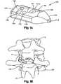
- FIG. 1Ais a perspective view of a first illustrative embodiment of an interspinous process spacer according to the invention
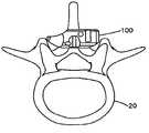
- FIG. 1Bis a perspective view of the interspinous process spacer of FIG. 1A inserted between the spinous processes of two vertebrae;
- FIGS. 2-4are top, front side, and bottom views, respectively, of the interspinous process spacer of FIGS. 1A and 1B ;
- FIG. 5is a top view of another illustrative embodiment of an interspinous process spacer according to the invention.
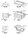
- FIGS. 6A and 6Bare end and perspective views, respectively, of a portion of a multi-piece interspinous process spacer
- FIGS. 7 and 8are end and perspective views, respectively, of a multi-piece interspinous process spacer after assembly of the portions of FIGS. 6A and 6B ;
- FIGS. 9 and 10are end and perspective views, respectively, of the multi-piece interspinous process spacer of FIGS. 7 and 8 ;
- FIG. 11is a sagittal schematic view of a spine showing a first spacer having horizontally stacked portions and a second spacer having vertically stacked portions;
- FIGS. 12 and 13are end and perspective views, respectively, of another embodiment of a portion of a multi-piece interspinous process spacer
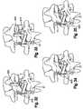
- FIGS. 14 , 15 and 16are cranial views of a spine showing lateral insertion of an interspinous process spacer
- FIG. 17is a perspective view of an embodiment of a perforator device
- FIG. 18is a perspective view of an embodiment of a dilator device
- FIG. 19is a perspective view of an embodiment of a distractor device
- FIG. 20is a perspective view of an embodiment of an inserter device
- FIG. 21is a perspective view of an embodiment of a spacer trial
- FIG. 22is a perspective view of the inserter device of FIG. 20 holding the trial of FIG. 21 ;
- FIG. 23is a close-up perspective view of another embodiment of an inserter device.
- FIG. 24is a close-up perspective view of another embodiment of a spacer trial.
- FIG. 25is a close-up perspective view of the inserter device of FIG. 23 holding the trial of FIG. 24 ;
- FIG. 26is a perspective view of an embodiment of a cord passer device
- FIG. 27is a top view of another embodiment of an interspinous process spacer
- FIG. 28is a perspective view of an embodiment of a locking pin for use with the interspinous process spacer of FIG. 27 ;
- FIG. 29is a side view of the interspinous process spacer of FIG. 27 ;
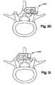
- FIGS. 30 and 31are cranial views of a spine showing lateral insertion of the interspinous process spacer of FIG. 27 ;
- FIGS. 32-35are perspective views showing insertion of the interspinous process spacer of FIG. 27 between spinous processes of two vertebrae and locking of the spacer with the pin of FIG. 28 ;
- FIGS. 36 and 37are top and perspective views, respectively, of another embodiment of an interspinous process spacer and locking pin.
- FIGS. 38 and 39are perspective views of the interspinous process spacer of FIGS. 36 and 37 , showing engagement of the locking pin with the body of the interspinous process spacer.
- FIGS. 1-3show a first embodiment of an interspinous spacer ( 100 ).
- the spacer ( 100 )may be generally rectangular and have an upper face ( 106 ) that generally opposes a lower face ( 105 ), front and back sides ( 104 , 103 ) that generally oppose each other, an end side ( 107 ), and a nose ( 110 ) that generally opposes the end side ( 107 ).
- the spacer ( 100 )preferably has rounded edges ( 108 ) between the upper face ( 106 ) and the front ( 104 ), end ( 107 ), and back sides ( 103 ) and between the lower face ( 105 ) and the front ( 104 ), end ( 107 ), and back sides ( 103 ). Radiuses of curvature for the rounded edges are each preferably about 1.5 mm. Alternatively, the radiuses can be of other dimensions and do not have to be the same.
- the spacer ( 100 )may include one or more depressions ( 101 ) extending laterally across the upper ( 106 ) and/or lower face ( 105 ). Such depressions ( 101 ) are preferably dimensioned and shaped to receive a spinous process and may be curved or substantially flat and planar.
- the lower face ( 105 )has a depression ( 101 ) having essentially the same dimensions and position as a corresponding depression ( 101 ) of the upper face ( 106 ).
- depressions ( 101 ) on the upper and/or lower faces ( 106 , 105 )may result in reduced, and preferably minimized, bone contact between the spacer ( 100 ) and the vertebrae.
- the upper and/or lower depressions ( 101 )may have any desired radius and/or depth.
- the depression ( 101 ) on the upper face ( 106 )has a radius of curvature of about 6 mm and a depth of about 0.5 mm.
- the upper and/or lower depression ( 101 )may have other radiuses and depths and can have radiuses and depths different than each other.
- the one or more depressions ( 101 )may also be positioned as desired.
- the center ( 101 a ) of the upper depression ( 101 )is positioned at a distance of about 9 mm from the end side.
- the one or more depressions ( 1101 )may be positioned at other distances from the end side.
- the body of the spacer ( 100 )may also include one or more holes ( 102 ) as shown in FIG. 1 .
- Such holes ( 102 )preferably extend through the spacer ( 100 ), e.g. from the upper face ( 106 ) to the lower face ( 105 ).
- the one or more holes ( 102 )may de dimensioned to pass a fixation strap, wire, cord, or the like, for example as described in U.S. Provisional Patent Application No. 60/688,359, filed Jun. 6, 2005 and entitled “Implant for Spinal Stabilization and its Method of Use”, which is incorporated by reference herein in its entirety.
- one or more of the holes ( 102 )may be threaded to accept threaded fixation devices (that may be screwed into position) and the holes ( 102 ) may not extend completely through the spacer ( 100 ).
- two holes ( 102 ) extending through the spacer ( 100 )each have a diameter of about 2.5 mm, and are spaced apart by a center-to-center distance of about 8 nm.
- the holes ( 102 )can have other center-to-center distances and other diameters, which can be different than each other.
- the spacer ( 100 )may pass through the spacer ( 100 ) at an oblique angle.
- the spacer ( 100 )alternatively may have other numbers of holes ( 102 ) or attachment points, and the holes or attachment points need not be on upper face and/or lower face.
- the nose ( 110 ) of the spacer ( 100 )may have a generally tapered shape, and extend preferably integrally from the upper face ( 106 ), lower face ( 105 ), front side ( 104 ) and back side ( 103 ) of the spacer ( 100 ).
- the nose ( 110 )may taper distally and inwardly to form a generally pointed or rounded distal tip ( 113 ).
- the tapered surfacesmay be curved or substantially flat planar surfaces.
- the nose ( 110 )is asymmetrical, for example including front edge ( 112 ) of the nose and back edge ( 111 ) of the nose that have different directions and/or radiuses of curvature. For example, as shown in FIGS.
- the front edge ( 112 ) of the nosemay be concave and have a radius of between about 10 mm and about 20 mm, more preferably about 15 mm
- the back edge ( 111 ) of the nosee.g., from the back side ( 103 ) of the spacer to the tip ( 113 )
- the radiusescan be of different dimensions and may be different from each other.
- the nose ( 110 )may have a generally symmetrical shape, for example as shown in FIG. 5 .
- the radiuses of the edges of the nose ( 110 ) from the back side ( 103 ) to the tip ( 113 ) and from the front side ( 104 ) to the tipmay be between about 10 mm and about 20 mm, more preferably about 14 mm.
- the radiuses of the nose ( 110 ) from the front side ( 104 ) to the tip ( 113 ) and from the back side ( 103 ) to the tip ( 113 )may be of other values and can be different from each other.
- the spacer ( 100 )may include one or more engagement, or interface, features ( 120 ).
- the spacer ( 100 )may include an engagement feature ( 120 ), also referred to as an inserter interface, to interface with an implant holder device.
- the engagement feature ( 120 )may include one or more generally planar and opposing recessed surfaces ( 123 , 124 ), or recesses, in the upper and lower faces ( 106 , 105 ), for example near the end ( 107 ) of the body of the spacer ( 100 ).
- Each recessmay be defined by one or more walls, for example an end wall ( 122 ), a back wall ( 125 ) and a side wall ( 122 ), such that each recess is accessible to an implant holder or other device from the front side of the spacer ( 100 ).
- the upper and lower recessed surfaces ( 123 , 124 )may be engaged by opposable jaws of an inserter device ( 4000 ) (e.g., as shown in FIG. 20 ), a forceps, or another device or tool adapted to grip or hold the spacer.
- the upper recess of the engagement feature ( 120 )has a height (e.g., distance from the upper face to the recessed surface) of about 3 mm, a depth (e.g., distance from the front side of the spacer to the back wall of the engagement feature) of about 7 mm, and a width (e.g., distance from the end wall to the side wall of the recess) of approximately 4 mm.
- the lower engagement feature ( 120 ) recesshas approximately the same dimensions as the upper engagement feature ( 120 ) recess.
- the engagement feature recessesmay have other dimensions, and may be different from each other.
- a spacer ( 100 )may have any desired length, width, and thickness.
- the lengthmay be between about 20 and 40 mm, more preferably between about 24 and 35 mm.
- the width and thicknessare preferably dimensionally paired and may be variable depending on the spinal application.
- the spacers ( 100 )are provided in a variety of sizes with thickness increasing in any desired increments, e.g., 2 mm increments.
- Illustrative, representative thicknesses, or heightcould be about 6 mm to about 16 mm, for example.
- the width of the spacer ( 100 )may be paired to the thickness, for example about 4 mm greater than the thickness.
- Illustrative, representative widthscould be about 10 mm to about 20 mm, for example.
- the spacers ( 100 )may be of other lengths, widths, and thicknesses.
- the spacers ( 100 )are made from bone, and more preferably from a single piece of cortical or other bone. Cortical bone may reduce and preferably minimizes the possibility of bone fusion.
- the spacer ( 100 )may be provided with a coating to minimize, resist, or prevent the possibility of bone fusion.
- a spacer ( 100 )is made from allograft bone. In other embodiments, autograft bone may be used.
- the spacer ( 100 )may be made of biocompatible materials such as, for example, PEEK, polycarbonate urethane, silicon polycarbonate urethane, or other polymer and plastic materials.
- the spacer ( 100 )may also be made of metals, such as, for example, titanium or stainless steel, and may also be made of composites, ceramics, or combinations of materials.
- a spacer ( 100 ) or other implantmay be inserted laterally into an interspinous space, for example through a small, posterior midline incision.
- Such an approachmay allow preservation of the supraspinous ligament.
- One or more spacers ( 100 )may be placed between spinous processes ( 11 , 21 ) of adjacent vertebrae ( 10 , 20 ) and result in distraction of the spinous processes ( 11 , 21 ) which may limit extension of the spine.
- implantation of an interspinous processmay inhibit or prevent the narrowing of the spinal canal and neural foramen at the level of treatment, thereby relieving pain or other symptoms.
- Preservation of the supraspinous ligamentmay provide additional stability, for example by keeping the implant from migrating posteriorly.
- a spacer ( 100 )may be fabricated or formed using a number of bone pieces or units. For example, due to a relatively large size of spacer implants (for example, greater than 5 mm in height, more preferably ranging anywhere from 8 to 14 mm or more in height over the depression), it may not be practical to fabricate the spacer from a single piece of bone.
- multiple pieces ( 500 ), or units,are used to construct an interspinous process spacer ( 100 ), it may be preferable to connect the units, for example using one or more connectors or connection features. Such connection features may be fabricated or otherwise integrated within one or more of the units ( 500 ).
- one or more of the units ( 500 )may be fabricated to include male and/or female dovetail connections ( 150 , 140 ) as shown in FIGS. 6A and 6B .
- Such dovetail connectionpreferably only permits translation along one direction between mating parts.
- a hole ( 160 )may be drilled across all of them and a dowel or pin ( 170 ), e.g., which may also be made from bone, may be pressed into the hole ( 160 ) to secure the assembly.
- An interference fit between the hole ( 160 ) and the pin ( 170 )may hold the entire assembly together.
- the pin ( 170 )can be threaded and may be screwed into the hole ( 160 ).
- the hole ( 160 )may be substantially perpendicular to the surface ( 180 ) of the multiple pieces ( 500 ) or be angled with respect to the surface ( 180 ) of the multiple pieces ( 500 ).
- the angled holes ( 160 ) and pins ( 170 )may be oriented in the same, different or opposite directions from one another.
- One or more additional pins ( 170 )may be used to provide extra stability if desired.
- cement or adhesivemay be used to couple the pieces together.
- interspinous process spacerscomprise other biocompatible materials instead of or in addition to bone.
- a spacer unit ( 500 )may have one male ( 150 ) and one female ( 140 ) dovetail connection.
- FIGS. 7 and 8show a multi-piece ( 600 ) construction of stacked units connected ( 500 ) using dovetail connections.
- Such a basic building block, with one male ( 150 ) and one female ( 140 ) dovetail connection,may be used for the internal layers as shown.
- the entire assembly ( 600 )may be held together using zero, one, two or more pins ( 170 ).
- FIGS. 9 and 10show an example of finished interspinous process spacer ( 200 ) made from multiple pieces or units ( 500 ).
- FIGS. 7 and 8shows five ( 500 ) units of substantially identical thickness.
- the number and thickness of the individual piecescould vary.
- a basic building blockhas one male ( 150 ) and one female ( 140 ) dovetail connection.
- each piece ( 500 )could have any number of dovetail connections, male or female.
- the central piece in the five layer stackmay have two female dovetail connections ( 140 ).
- the next two inner piecescould have one male ( 150 ) and one female ( 140 ) dovetail, and the outer pieces could have one male ( 150 ) dovetail.
- the dovetail connections of the basic building blockpreferably, although not necessarily run all the way through the part, e.g., a “thru dovetail”.
- a blind dovetail ( 190 ) as shown in FIGS. 12 and 13may be employed to provide additional resistance between mating parts in at least one direction of translation that a standard thru dovetail does not.
- FIGS. 9 and 10show the assembled pieces ( 500 ) as horizontal layers (horizontal stacking) in the finished implant ( 200 ).
- the pieces ( 500 )could have been assembled as vertical layers (vertical stacking) ( 400 ) instead, e.g. as shown in FIG. 11 . If one or more of the individual horizontal layers were actually made from two or more vertically stacked pieces ( 500 ), a hybrid combining both horizontal ( 300 ) and vertical stacked ( 400 ) pieces could be constructed.
- the interspinous process spacer ( 100 )is preferably inserted in a curved lateral fashion, for example so as to preserve the supraspinous ligament.
- the anterior surface (upper face 106 ) of the spacer ( 100 )may be curved in a similar manner to present a smaller profile to the surrounding tissue upon insertion. For example, it is placed as far anterior as possible to minimize the possibility of posterior migration and dislodgement.
- the implant ( 100 )may come in different size footprints and heights to adapt to variations in patient anatomy.
- an interspinous process spacer100
- an interspinous process spacer100
- implanting one or more spacersmay be included separately, or in a kit or set.
- the surgeonmay use a perforator, e.g., such as the perforator ( 1000 ) shown in FIG. 17 or another suitable tool, to help locate the interspinous space radiographically.
- a perforatore.g., such as the perforator ( 1000 ) shown in FIG. 17 or another suitable tool
- the surgeonmay use the sharp tip ( 1100 ) of the perforator ( 1000 ) to split the interspinous ligament (ISL), while keeping the supraspinous ligament (SSL) intact.
- surgeonmay then use the blunt tip ( 2100 ) of a dilator ( 2000 ), e.g., such as the dilator ( 2000 ) shown in FIG. 18 or another suitable tool, to further increase the size of the opening in the ISL.
- a dilatore.g., such as the dilator ( 2000 ) shown in FIG. 18 or another suitable tool
- the surgeonmay insert the jaws ( 3100 ) of a distractor ( 3000 ), e.g., such as the distractor ( 3000 ) shown in FIG. 19 or anther suitable tool, into the opening in the ISL such that the opposable jaws ( 3100 ) of the distractor ( 3000 ) engage the spinous processes ( 11 , 21 ) of the adjacent vertebrae ( 10 , 20 ), and distract the spinous processes ( 11 , 21 ) as much as possible.
- the open distractor ( 3000 )may be left in place for a desired amount of time, e.g., a few minutes or more, to allow the SSL to stretch out. During this time, the surgeon can assess the mobility of the segment.
- a scale ( 3400 ) on the threaded rod ( 3200 ) at the back of the handle ( 3300 ) of the distractor ( 3000 )may be used to indicate the amount of interspinous space distraction, e.g., by the amount of distractor jaw ( 3100 ) movement.
- the surgeonmay use an inserter ( 4000 ), e.g., such as the inserter ( 4000 ) shown in FIG. 20 or another suitable tool, to grasp the appropriate sized ( 100 ) implant and insert it in the curved lateral fashion described previously.
- the spacer ( 100 )may be inserted by other means and via different pathways.
- the surgeoncan use an inserter ( 4000 ) to grasp an appropriate sized trial ( 700 ), e.g., such as that shown in FIGS. 21 and 22 , to assess proper implant sizing. Once the proper size has been confirmed, the correct implant size can then be inserted.
- FIGS. 23-25show an example of an alternate inserter interface ( 4100 ) and trial ( 700 ) adapted to engage with the interface.
- the inserter interface ( 4100 )may have a width that is wider, e.g., much wider, than that of above-described embodiments.
- the inserter interface ( 4100 )may be dimensioned such that the end wall on the alternate trial engagement feature/implant inserter interface ( 120 a ), e.g., as shown in FIG. 24 , is removed.
- the jaws of the inserter interface ( 4100 )may include engagement pins ( 4111 ) which protrude beyond the height of the teeth ( 4110 ) as shown in FIG. 23 .
- FIG. 25shows an example the alternate inserter interface ( 120 a ) of FIG. 23 engaged with the trial ( 800 ) of FIG. 24 .
- the surgeonmay use a flexible cord (e.g., a cable, suture, wire, etc.) to secure the implant ( 100 ) to one or more of the spinous processes ( 11 , 21 ).
- a flexible corde.g., a cable, suture, wire, etc.
- the surgeonmay, for example, pass one end of the cord through the ISL of the neighboring interspinous space to access the opposite side.
- FIG. 26shows an embodiment of a cord passer ( 5000 ) which may be used to facilitate passing the cord.
- the bent tube ( 5100 ) on the end of the passermay include two openings: the insertion end ( 5110 ) and the passing end ( 5120 ).
- the tip ( 5111 ) of the passermay be placed on the opposite side of the spinous processes from that of the free end of the flexible cord.
- the sharp edge on the insertion end ( 5110 )may be used to split the ISL of the neighboring interspinous space. This allows the insertion end ( 5110 ) to pass through the ISL onto the same side as the end of the flexible cord while the passing end ( 5120 ) remains on the opposite side.
- the end of the flexible cordmay then be fed into the insertion end ( 5110 ) opening until it comes out of the opening in the passing end ( 5120 ) on the opposite side. Once this is done, the insertion end ( 5110 ) may be retracted back to its original side, and the cord passer ( 5000 ) can be safely removed.
- the approach and technique described aboveis only one method for inserting an ISPS.
- a surgeonmay choose to use none or only some of the instruments shown, or may chose to use other instruments that may have some of the same or similar features to those described above. For instance, the surgeon may not need to use the dilator ( 2000 ) if the opening created by the perforator ( 1000 ) is large enough to accommodate the tips ( 3111 ) of the distractor ( 3000 ). Similarly, the surgeon may choose not to use the perforator ( 1000 ) if the tips ( 3111 ) on the distractor ( 3000 ) are sharp enough to split the ISL at the desired location.
- judicious use of a second distractormay permit the insertion of the trial ( 700 ) and/or ISPS while this second distractor ( 3000 ) remains in place.
- the first distractor ( 3000 )may be removed.
- a second distractorfor example with a beak width equal to the reading on the scale indicator, may be inserted such that its jaws ( 3100 ) are perpendicular to that of the first distractor ( 3000 ) (when it was in place).
- the second distractormay then be actuated to open the ISL further while maintaining the existing interspinous space distraction. With the jaws of the second distractor opened wide enough to accommodate the width of the implant ( 100 ), the trial ( 700 ) and/or implant ( 100 ) can be safely inserted. This simultaneous insertion while distracting the spinous processes could greatly reduce the insertion load needed to insert the implant ( 100 ). Once the implant ( 100 ) is in place, the second distractor can be carefully removed.
- the second distractorcould be inserted and actuated with the first distractor ( 3000 ) in place.
- Thismay require the beak ( 3110 ) width of the second distractor to be slightly smaller than the opening between the first distractor jaws ( 3100 ).
- the jaws of the second distractoropened wide enough to accommodate the ISPS width (e.g., which is equal to or larger than the ISPS height), the jaws ( 3100 ) on the first distractor ( 3000 ) can be safely closed and removed.
- a direct posterior insertion approach of the ISPSmay be employed as an alternative to a lateral insertion approach.
- the surgeonmay take down the supraspinous ligament and/or the interspinous ligament.
- FIGS. 27-31show an alternative implant ( 900 ), or stand-alone device, made from multiple components.
- the main body ( 910 ) in this examplemay have a tip or nose ( 911 ) that is more symmetrical (e.g., rather than curved as shown in above-described embodiments).
- Such symmetrical configurationmay permit, for example, a more direct lateral insertion as shown in FIGS. 30-31 .
- the opposite end of the spacer ( 900 )may include a high wall ( 912 ) protruding from the top ( 916 ) and bottom ( 917 ) surfaces of the main body ( 910 ).
- This high wall ( 912 )is preferably large enough to engage the lateral surface of the spinous process above and below the body.
- a hole ( 914 a ) and slot ( 914 b ) configurationmay run through the body.
- the hole and slot configuration ( 914 )is preferably sized to permit the insertion of a locking pin ( 920 ).
- FIG. 28shows an exemplary locking pin ( 920 ).
- the locking pin ( 920 )may have two heads ( 921 a , 921 b ) and a cylindrical midsection ( 922 ).
- the heads ( 921 a , 921 b )are preferably sized to slide through the slots ( 914 b ) in the main body ( 910 ) of the spacer ( 900 ).
- the cylindrical midsection ( 922 )is preferably also sized to slide through the hole ( 914 a ) in the main body ( 910 ).
- the locking pin ( 920 )preferably has a length which is the same or similar to the length of the high wall ( 912 ) on the main body ( 910 ).
- the locking pin ( 920 )may be assembled, for example as shown in FIGS. 32-35 .
- the locking pin ( 920 )is oriented so that it can be inserted into the hole and slot configuration ( 914 ) in the main body, for example using an insertion tool, forceps, or other device (not shown).
- the entire locking pin ( 920 )may be rotated, e.g., approximately 90 degrees as shown in FIG.
- the upper and lower heads ( 921 a , 921 b ) on the locking pin ( 920 )are preferably tall enough to engage the lateral surface of the spinous process above and below the body when locked as shown in FIG. 35 , capturing the spinous processes ( 11 , 21 ) between the locking pin ( 920 ) and high wall ( 912 ) of the main body ( 910 ) of the spacer ( 900 ).
- the heads ( 921 a , 921 b ) of the locking pin ( 920 )may rotate with respect to the midsection, and may be rotated, e.g., using a forceps or other tool after insertion to lock the pin.
- FIGS. 36-39show another embodiment ( 6000 ) using a slightly different locking pin ( 6200 ) mechanism.
- a locking pin ( 6200 )is inserted into the hole ( 6110 ) from the side, e.g., through a slot ( 6111 ) in the front side of the hole ( 6110 ) as shown in FIG. 36 .
- the midsection ( 6210 ) of the pin ( 6200 )preferably has one or more flat sides ( 6211 ) and one or more rounded sides ( 6212 ) as shown in FIG. 37 .
- the midsection of the pinmay be thinner between the flat surfaces ( 6211 ) so that it can slide through the slot ( 6111 ) and into the larger hole ( 6110 in the spacer implant ( 6000 ), and thicker between the rounded sides ( 6212 ) so that once the pin ( 6200 ) is located in the hole ( 6110 ) and rotated, e.g., approximately 90° the pin ( 6200 ) can not slide out of the slot ( 6111 ).
- the enlarged head areas ( 6220 )are sized to hold the implant ( 6000 ) between the spinous process in conjunction with the raised walls ( 6120 ) on the back end ( 6001 ) of the implant.
- the locking pinmay be a threaded pin, while the hole and slot configuration may be replaced a corresponding by a threaded hole.
- the high wall on the main bodycould also be replaced by another locking pin.
- the slot in the hole and slot configurationcould permit the addition of flexible attachment methods (e.g., a cable, suture, wire, etc.).
- the flexible attachment cordmay provide interference with the locking pin, insuring it did not disassemble from the main body. Interspinous process spacers with various combinations of the features previously described above are envisioned.
- interspinous process spacer from boneHaving a large mismatch in mechanical properties between implant and surrounding bone can often lead to resorption of the surrounding bone.
- One of the advantages of making the interspinous process spacer from boneis that its mechanical properties may be similar to that of the surrounding bone and thus minimize the likelihood of this occurring.
- Other materials, like PEEK for example, that have mechanical properties similar to bonecould also be used.
- other common implantable materialslike titanium, stainless steel, ceramics, and composites could also be used.
- this implant design and insertion methodis not limited the lumbar spine as shown, but could easily be adapted for other areas of the spine or other joints or body parts.
Landscapes
- Health & Medical Sciences (AREA)
- Orthopedic Medicine & Surgery (AREA)
- Life Sciences & Earth Sciences (AREA)
- Neurology (AREA)
- Surgery (AREA)
- Heart & Thoracic Surgery (AREA)
- Engineering & Computer Science (AREA)
- Biomedical Technology (AREA)
- Nuclear Medicine, Radiotherapy & Molecular Imaging (AREA)
- Medical Informatics (AREA)
- Molecular Biology (AREA)
- Animal Behavior & Ethology (AREA)
- General Health & Medical Sciences (AREA)
- Public Health (AREA)
- Veterinary Medicine (AREA)
- Prostheses (AREA)
Abstract
Description
Claims (18)
Priority Applications (1)
| Application Number | Priority Date | Filing Date | Title |
|---|---|---|---|
| US12/162,939US8500778B2 (en) | 2006-02-01 | 2007-01-31 | Interspinous process spacer |
Applications Claiming Priority (3)
| Application Number | Priority Date | Filing Date | Title |
|---|---|---|---|
| US76406906P | 2006-02-01 | 2006-02-01 | |
| US12/162,939US8500778B2 (en) | 2006-02-01 | 2007-01-31 | Interspinous process spacer |
| PCT/US2007/002791WO2007089905A2 (en) | 2006-02-01 | 2007-01-31 | Interspinous process spacer |
Publications (2)
| Publication Number | Publication Date |
|---|---|
| US20090306715A1 US20090306715A1 (en) | 2009-12-10 |
| US8500778B2true US8500778B2 (en) | 2013-08-06 |
Family
ID=38261487
Family Applications (1)
| Application Number | Title | Priority Date | Filing Date |
|---|---|---|---|
| US12/162,939Expired - Fee RelatedUS8500778B2 (en) | 2006-02-01 | 2007-01-31 | Interspinous process spacer |
Country Status (4)
| Country | Link |
|---|---|
| US (1) | US8500778B2 (en) |
| EP (1) | EP1978900B1 (en) |
| AT (1) | ATE548000T1 (en) |
| WO (1) | WO2007089905A2 (en) |
Cited By (4)
| Publication number | Priority date | Publication date | Assignee | Title |
|---|---|---|---|---|
| US20080015609A1 (en)* | 2006-04-28 | 2008-01-17 | Trautwein Frank T | Instrument system for use with an interspinous implant |
| US9149306B2 (en) | 2011-06-21 | 2015-10-06 | Seaspine, Inc. | Spinous process device |
| US20170027618A1 (en)* | 2007-04-10 | 2017-02-02 | Life Spine, Inc. | Adjustable spine distraction implant |
| US10117682B2 (en) | 2008-04-10 | 2018-11-06 | Life Spine, Inc. | Adjustable spine distraction implant |
Families Citing this family (73)
| Publication number | Priority date | Publication date | Assignee | Title |
|---|---|---|---|---|
| FR2871366A1 (en) | 2004-06-09 | 2005-12-16 | Ceravic Soc Par Actions Simpli | PROSTHETIC EXPANSIBLE BONE IMPLANT |
| US8425559B2 (en) | 2004-10-20 | 2013-04-23 | Vertiflex, Inc. | Systems and methods for posterior dynamic stabilization of the spine |
| US8123807B2 (en) | 2004-10-20 | 2012-02-28 | Vertiflex, Inc. | Systems and methods for posterior dynamic stabilization of the spine |
| US9119680B2 (en) | 2004-10-20 | 2015-09-01 | Vertiflex, Inc. | Interspinous spacer |
| US8317864B2 (en) | 2004-10-20 | 2012-11-27 | The Board Of Trustees Of The Leland Stanford Junior University | Systems and methods for posterior dynamic stabilization of the spine |
| US9023084B2 (en) | 2004-10-20 | 2015-05-05 | The Board Of Trustees Of The Leland Stanford Junior University | Systems and methods for stabilizing the motion or adjusting the position of the spine |
| US8613747B2 (en) | 2004-10-20 | 2013-12-24 | Vertiflex, Inc. | Spacer insertion instrument |
| US8123782B2 (en) | 2004-10-20 | 2012-02-28 | Vertiflex, Inc. | Interspinous spacer |
| US8277488B2 (en) | 2004-10-20 | 2012-10-02 | Vertiflex, Inc. | Interspinous spacer |
| US8409282B2 (en) | 2004-10-20 | 2013-04-02 | Vertiflex, Inc. | Systems and methods for posterior dynamic stabilization of the spine |
| US8128662B2 (en) | 2004-10-20 | 2012-03-06 | Vertiflex, Inc. | Minimally invasive tooling for delivery of interspinous spacer |
| US9161783B2 (en) | 2004-10-20 | 2015-10-20 | Vertiflex, Inc. | Interspinous spacer |
| US8945183B2 (en) | 2004-10-20 | 2015-02-03 | Vertiflex, Inc. | Interspinous process spacer instrument system with deployment indicator |
| US7763074B2 (en) | 2004-10-20 | 2010-07-27 | The Board Of Trustees Of The Leland Stanford Junior University | Systems and methods for posterior dynamic stabilization of the spine |
| US8012207B2 (en) | 2004-10-20 | 2011-09-06 | Vertiflex, Inc. | Systems and methods for posterior dynamic stabilization of the spine |
| US8273108B2 (en) | 2004-10-20 | 2012-09-25 | Vertiflex, Inc. | Interspinous spacer |
| US8167944B2 (en) | 2004-10-20 | 2012-05-01 | The Board Of Trustees Of The Leland Stanford Junior University | Systems and methods for posterior dynamic stabilization of the spine |
| US8152837B2 (en) | 2004-10-20 | 2012-04-10 | The Board Of Trustees Of The Leland Stanford Junior University | Systems and methods for posterior dynamic stabilization of the spine |
| US8241330B2 (en) | 2007-01-11 | 2012-08-14 | Lanx, Inc. | Spinous process implants and associated methods |
| US9055981B2 (en) | 2004-10-25 | 2015-06-16 | Lanx, Inc. | Spinal implants and methods |
| EP2219538B1 (en) | 2004-12-06 | 2022-07-06 | Vertiflex, Inc. | Spacer insertion instrument |
| US8562685B2 (en) | 2005-05-06 | 2013-10-22 | Titan Spine, Llc | Spinal implant and integration plate for optimizing vertebral endplate contact load-bearing edges |
| US8814939B2 (en) | 2005-05-06 | 2014-08-26 | Titan Spine, Llc | Implants having three distinct surfaces |
| US8591590B2 (en) | 2005-05-06 | 2013-11-26 | Titan Spine, Llc | Spinal implant having a transverse aperture |
| US9125756B2 (en) | 2005-05-06 | 2015-09-08 | Titan Spine, Llc | Processes for producing regular repeating patterns on surfaces of interbody devices |
| US8758443B2 (en) | 2005-05-06 | 2014-06-24 | Titan Spine, Llc | Implants with integration surfaces having regular repeating surface patterns |
| US8551176B2 (en) | 2005-05-06 | 2013-10-08 | Titan Spine, Llc | Spinal implant having a passage for enhancing contact between bone graft material and cortical endplate bone |
| US20120312779A1 (en) | 2005-05-06 | 2012-12-13 | Titian Spine, LLC | Methods for manufacturing implants having integration surfaces |
| US8480749B2 (en) | 2005-05-06 | 2013-07-09 | Titan Spine, Llc | Friction fit and vertebral endplate-preserving spinal implant |
| US8545568B2 (en) | 2005-05-06 | 2013-10-01 | Titan Spine, Llc | Method of using instruments and interbody spinal implants to enhance distraction |
| US8758442B2 (en) | 2005-05-06 | 2014-06-24 | Titan Spine, Llc | Composite implants having integration surfaces composed of a regular repeating pattern |
| US8435302B2 (en) | 2005-05-06 | 2013-05-07 | Titan Spine, Llc | Instruments and interbody spinal implants enhancing disc space distraction |
| US8403991B2 (en) | 2005-05-06 | 2013-03-26 | Titan Spine Llc | Implant with critical ratio of load bearing surface area to central opening area |
| US8585765B2 (en) | 2005-05-06 | 2013-11-19 | Titan Spine, Llc | Endplate-preserving spinal implant having a raised expulsion-resistant edge |
| US8585766B2 (en) | 2005-05-06 | 2013-11-19 | Titan Spine, Llc | Endplate-preserving spinal implant with an integration plate having durable connectors |
| US8617248B2 (en) | 2005-05-06 | 2013-12-31 | Titan Spine, Llc | Spinal implant having variable ratios of the integration surface area to the axial passage area |
| US11096796B2 (en) | 2005-05-06 | 2021-08-24 | Titan Spine, Llc | Interbody spinal implant having a roughened surface topography on one or more internal surfaces |
| US8992622B2 (en) | 2005-05-06 | 2015-03-31 | Titan Spine, Llc | Interbody spinal implant having a roughened surface topography |
| US9168147B2 (en) | 2005-05-06 | 2015-10-27 | Titan Spine, Llc | Self-deploying locking screw retention device |
| US8262737B2 (en) | 2005-05-06 | 2012-09-11 | Titan Spine, Llc | Composite interbody spinal implant having openings of predetermined size and shape |
| US8585767B2 (en) | 2005-05-06 | 2013-11-19 | Titan Spine, Llc | Endplate-preserving spinal implant with an integration plate having durable connectors |
| US8562684B2 (en) | 2005-05-06 | 2013-10-22 | Titan Spine, Llc | Endplate-preserving spinal implant with an integration plate having a roughened surface topography |
| US8845726B2 (en) | 2006-10-18 | 2014-09-30 | Vertiflex, Inc. | Dilator |
| US9247968B2 (en) | 2007-01-11 | 2016-02-02 | Lanx, Inc. | Spinous process implants and associated methods |
| US9265532B2 (en) | 2007-01-11 | 2016-02-23 | Lanx, Inc. | Interspinous implants and methods |
| AU2008241447B2 (en) | 2007-04-16 | 2014-03-27 | Vertiflex, Inc. | Interspinous spacer |
| AU2009206098B2 (en) | 2008-01-15 | 2014-10-30 | Vertiflex, Inc. | Interspinous spacer |
| WO2009125242A1 (en)* | 2008-04-08 | 2009-10-15 | Vexim | Apparatus for restoration of the spine and methods of use thereof |
| EP2323574B1 (en)* | 2008-08-13 | 2012-02-15 | Synthes GmbH | Interspinous spacer assembly |
| US20100106252A1 (en) | 2008-10-29 | 2010-04-29 | Kohm Andrew C | Spinal implants having multiple movable members |
| US8945184B2 (en)* | 2009-03-13 | 2015-02-03 | Spinal Simplicity Llc. | Interspinous process implant and fusion cage spacer |
| US8998954B2 (en)* | 2009-08-03 | 2015-04-07 | Life Spine, Inc. | Spinous process spacer |
| US9402656B2 (en)* | 2009-09-11 | 2016-08-02 | Globus Medical, Inc. | Spinous process fusion devices |
| US8740948B2 (en) | 2009-12-15 | 2014-06-03 | Vertiflex, Inc. | Spinal spacer for cervical and other vertebra, and associated systems and methods |
| US20120215262A1 (en)* | 2011-02-16 | 2012-08-23 | Interventional Spine, Inc. | Spinous process spacer and implantation procedure |
| US9498560B2 (en) | 2011-03-04 | 2016-11-22 | Spinefrontier, Inc | Interspinous spacer implant |
| US11812923B2 (en) | 2011-10-07 | 2023-11-14 | Alan Villavicencio | Spinal fixation device |
| US8992619B2 (en) | 2011-11-01 | 2015-03-31 | Titan Spine, Llc | Microstructured implant surfaces |
| US8795167B2 (en) | 2011-11-15 | 2014-08-05 | Baxano Surgical, Inc. | Spinal therapy lateral approach access instruments |
| CA2880825C (en) | 2012-03-20 | 2021-03-16 | Titan Spine, Llc | Friction-fit spinal endplate and endplate-preserving method |
| EP2716261A1 (en) | 2012-10-02 | 2014-04-09 | Titan Spine, LLC | Implants with self-deploying anchors |
| US9498349B2 (en) | 2012-10-09 | 2016-11-22 | Titan Spine, Llc | Expandable spinal implant with expansion wedge and anchor |
| US9675303B2 (en) | 2013-03-15 | 2017-06-13 | Vertiflex, Inc. | Visualization systems, instruments and methods of using the same in spinal decompression procedures |
| FR3015221B1 (en) | 2013-12-23 | 2017-09-01 | Vexim | EXPANSIBLE INTRAVERTEBRAL IMPLANT SYSTEM WITH POSTERIOR PEDICULAR FIXATION |
| US10213231B2 (en) | 2014-01-28 | 2019-02-26 | Life Spine, Inc. | System and method for reducing and stabilizing a bone fracture |
| US9615935B2 (en) | 2014-01-30 | 2017-04-11 | Titan Spine, Llc | Thermally activated shape memory spring assemblies for implant expansion |
| AU2015256024B2 (en) | 2014-05-07 | 2020-03-05 | Vertiflex, Inc. | Spinal nerve decompression systems, dilation systems, and methods of using the same |
| US11135070B2 (en) | 2018-02-14 | 2021-10-05 | Titan Spine, Inc. | Modular adjustable corpectomy cage |
| US12396762B2 (en)* | 2020-04-08 | 2025-08-26 | Diametros Medical S.R.L. | Interspinous vertebral distractor |
| WO2023158581A1 (en) | 2022-02-15 | 2023-08-24 | Boston Scientific Neuromodulation Corporation | Interspinous spacer and systems utilizing the interspinous spacer |
| US12133664B2 (en) | 2022-12-13 | 2024-11-05 | Spinal Simplicity, Llc | Medical implant |
| US12433646B2 (en) | 2023-02-21 | 2025-10-07 | Boston Scientific Neuromodulation Corporation | Interspinous spacer with actuator locking arrangements and methods and systems |
| US12390340B2 (en) | 2023-03-15 | 2025-08-19 | Boston Scientific Neuromodulation Corporation | Interspinous spacer with a range of deployment positions and methods and systems |
Citations (111)
| Publication number | Priority date | Publication date | Assignee | Title |
|---|---|---|---|---|
| US4298993A (en)* | 1980-02-06 | 1981-11-10 | Kovaleva Irina D | Endoprosthesis of the body of the innominate bone |
| US4904261A (en)* | 1987-08-06 | 1990-02-27 | A. W. Showell (Surgicraft) Limited | Spinal implants |
| US4917704A (en)* | 1987-07-09 | 1990-04-17 | Sulzer Brothers Limited | Intervertebral prosthesis |
| US5011484A (en)* | 1987-11-16 | 1991-04-30 | Breard Francis H | Surgical implant for restricting the relative movement of vertebrae |
| US5059193A (en) | 1989-11-20 | 1991-10-22 | Spine-Tech, Inc. | Expandable spinal implant and surgical method |
| FR2722980A1 (en) | 1994-07-26 | 1996-02-02 | Samani Jacques | Spinal implant for securing adjacent pair of vertebrae |
| US5496318A (en) | 1993-01-08 | 1996-03-05 | Advanced Spine Fixation Systems, Inc. | Interspinous segmental spine fixation device |
| US5836948A (en)* | 1997-01-02 | 1998-11-17 | Saint Francis Medical Technologies, Llc | Spine distraction implant and method |
| US5980572A (en)* | 1997-04-15 | 1999-11-09 | Asahi Kogaku Kogyo Kabushiki Kaisha | Artificial spines |
| US6111164A (en)* | 1996-06-21 | 2000-08-29 | Musculoskeletal Transplant Foundation | Bone graft insert |
| US6235030B1 (en) | 1997-01-02 | 2001-05-22 | St. Francis Medical Technologies, Inc. | Spine distraction implant |
| US6261586B1 (en)* | 1997-06-11 | 2001-07-17 | Sdgi Holdings, Inc. | Bone graft composites and spacers |
| US20010012938A1 (en)* | 1997-01-02 | 2001-08-09 | Zucherman James F. | Spine distraction implant |
| US6332882B1 (en) | 1997-01-02 | 2001-12-25 | St. Francis Medical Technologies, Inc. | Spine distraction implant |
| WO2002007624A1 (en) | 2000-07-21 | 2002-01-31 | St. Francis Medical Technologies, Inc. | Spinal implants, insertion instruments, and methods of use |
| US20020029039A1 (en)* | 1997-01-02 | 2002-03-07 | Zucherman James F. | Supplemental spine fixation device and methods |
| US6451019B1 (en) | 1998-10-20 | 2002-09-17 | St. Francis Medical Technologies, Inc. | Supplemental spine fixation device and method |
| US6500177B1 (en) | 1998-05-19 | 2002-12-31 | Synthes (Usa) | Telescopic body for an external fixation system |
| WO2003007791A2 (en) | 2001-07-18 | 2003-01-30 | St. Francis Medical Technologies, Inc. | Interspinous process distraction system and method with positionable wing and method |
| US20030093153A1 (en)* | 2001-09-28 | 2003-05-15 | Banick Christopher M. | Skeletal stabilization implant |
| US6579318B2 (en)* | 2000-06-12 | 2003-06-17 | Ortho Development Corporation | Intervertebral spacer |
| EP1330987A1 (en) | 2002-01-28 | 2003-07-30 | Biomet Merck France | Interspinous vertebral implant |
| EP1334703A2 (en) | 2002-02-08 | 2003-08-13 | Showa IKA Kohgyo Co., Ltd. | Vertebral body distance retainer |
| US6613090B2 (en)* | 1998-01-23 | 2003-09-02 | Aesculap Ag & Co. Kg | Intervertebral implant |
| US6626944B1 (en)* | 1998-02-20 | 2003-09-30 | Jean Taylor | Interspinous prosthesis |
| US6652527B2 (en) | 1998-10-20 | 2003-11-25 | St. Francis Medical Technologies, Inc. | Supplemental spine fixation device and method |
| US6699288B2 (en)* | 2000-03-22 | 2004-03-02 | Scolio Gmbh | Cage-type intervertebral implant |
| US6733534B2 (en) | 2002-01-29 | 2004-05-11 | Sdgi Holdings, Inc. | System and method for spine spacing |
| US6749636B2 (en)* | 2001-04-02 | 2004-06-15 | Gary K. Michelson | Contoured spinal fusion implants made of bone or a bone composite material |
| US6761720B1 (en)* | 1999-10-15 | 2004-07-13 | Spine Next | Intervertebral implant |
| US20040162616A1 (en)* | 2002-10-21 | 2004-08-19 | Simonton T. Andrew | Systems and techniques for restoring and maintaining intervertebral anatomy |
| US20040186572A1 (en)* | 2002-12-19 | 2004-09-23 | Co-Linge Ag | Pair of lumbar interbody implants and method of fusing together adjoining vertebrae bodies |
| US20040210222A1 (en)* | 2001-02-28 | 2004-10-21 | Angelucci Christopher M. | Laminoplasty plates and methods of use |
| WO2005009300A1 (en) | 2003-07-24 | 2005-02-03 | Byung-Kwan Choi | Prosthesis for vertebra |
| US20050027360A1 (en)* | 2003-08-01 | 2005-02-03 | Webb Scott A. | Spinal implant |
| US20050055031A1 (en) | 2003-09-10 | 2005-03-10 | Roy Lim | Devices and methods for inserting spinal implants |
| US20050090829A1 (en)* | 2003-10-23 | 2005-04-28 | Osteotech, Inc. | Spinal bone chisels |
| US20050177238A1 (en)* | 2001-05-01 | 2005-08-11 | Khandkar Ashok C. | Radiolucent bone graft |
| US20050187625A1 (en)* | 2003-10-20 | 2005-08-25 | Howard Wolek | Vertebral body replacement apparatus and method |
| US20050203512A1 (en) | 2004-03-09 | 2005-09-15 | Depuy Spine, Inc. | Posterior process dynamic spacer |
| US20050203624A1 (en) | 2004-03-06 | 2005-09-15 | Depuy Spine, Inc. | Dynamized interspinal implant |
| US20050209603A1 (en) | 2003-12-02 | 2005-09-22 | St. Francis Medical Technologies, Inc. | Method for remediation of intervertebral disks |
| US6949123B2 (en)* | 1999-10-22 | 2005-09-27 | Archus Orthopedics Inc. | Facet arthroplasty devices and methods |
| US20050261768A1 (en) | 2004-05-21 | 2005-11-24 | Trieu Hai H | Interspinous spacer |
| US6974480B2 (en)* | 2001-05-03 | 2005-12-13 | Synthes (Usa) | Intervertebral implant for transforaminal posterior lumbar interbody fusion procedure |
| US7018413B2 (en)* | 2001-10-24 | 2006-03-28 | Tutogen Medical Gmbh | Modular system for spinal column fusion |
| US7029473B2 (en) | 1998-10-20 | 2006-04-18 | St. Francis Medical Technologies, Inc. | Deflectable spacer for use as an interspinous process implant and method |
| US20060085069A1 (en) | 2004-10-20 | 2006-04-20 | The Board Of Trustees Of The Leland Stanford Junior University | Systems and methods for posterior dynamic stabilization of the spine |
| US20060084988A1 (en) | 2004-10-20 | 2006-04-20 | The Board Of Trustees Of The Leland Stanford Junior University | Systems and methods for posterior dynamic stabilization of the spine |
| US20060085070A1 (en) | 2004-10-20 | 2006-04-20 | Vertiflex, Inc. | Systems and methods for posterior dynamic stabilization of the spine |
| US7048762B1 (en)* | 1997-08-27 | 2006-05-23 | Regeneration Technologies, Inc. | Elongated cortical bone implant |
| US7060096B1 (en)* | 1999-11-03 | 2006-06-13 | Tutogen Medical Gmbh | Implant consisting of bone material |
| US7060073B2 (en)* | 1999-10-21 | 2006-06-13 | Sdgi Holdings, Inc. | Devices and techniques for a posterior lateral disc space approach |
| US20060129243A1 (en)* | 2004-09-21 | 2006-06-15 | Wong Hee K | Interbody spinal device |
| WO2006064356A1 (en) | 2004-12-16 | 2006-06-22 | Doellinger Horst | Implant for the treatment of lumbar spinal canal stenosis |
| US20060184247A1 (en) | 2005-02-17 | 2006-08-17 | Edidin Avram A | Percutaneous spinal implants and methods |
| US20060184248A1 (en) | 2005-02-17 | 2006-08-17 | Edidin Avram A | Percutaneous spinal implants and methods |
| US20060224159A1 (en)* | 2005-03-31 | 2006-10-05 | Sdgi Holdings, Inc. | Intervertebral prosthetic device for spinal stabilization and method of implanting same |
| US20060235532A1 (en)* | 2003-01-20 | 2006-10-19 | Abbott Spine | Unit for treatment of the degeneration of an intervertebral disc |
| US20060241601A1 (en) | 2005-04-08 | 2006-10-26 | Trautwein Frank T | Interspinous vertebral and lumbosacral stabilization devices and methods of use |
| US20060241613A1 (en)* | 2005-04-12 | 2006-10-26 | Sdgi Holdings, Inc. | Implants and methods for inter-transverse process dynamic stabilization of a spinal motion segment |
| US20060247634A1 (en)* | 2005-05-02 | 2006-11-02 | Warner Kenneth D | Spinous Process Spacer Implant and Technique |
| US20060247623A1 (en)* | 2005-04-29 | 2006-11-02 | Sdgi Holdings, Inc. | Local delivery of an active agent from an orthopedic implant |
| US7137997B2 (en)* | 2003-12-29 | 2006-11-21 | Globus Medical, Inc. | Spinal fusion implant |
| US20060264938A1 (en) | 2005-03-21 | 2006-11-23 | St. Francis Medical Technologies, Inc. | Interspinous process implant having deployable wing and method of implantation |
| US20060271049A1 (en) | 2005-04-18 | 2006-11-30 | St. Francis Medical Technologies, Inc. | Interspinous process implant having deployable wings and method of implantation |
| US20060271194A1 (en)* | 2005-03-22 | 2006-11-30 | St. Francis Medical Technologies, Inc. | Interspinous process implant having deployable wing as an adjunct to spinal fusion and method of implantation |
| US20060293663A1 (en)* | 2005-04-21 | 2006-12-28 | Spine Wave, Inc. | Dynamic stabilization system for the spine |
| US20060293662A1 (en)* | 2005-06-13 | 2006-12-28 | Boyer Michael L Ii | Spinous process spacer |
| US20070043361A1 (en) | 2005-02-17 | 2007-02-22 | Malandain Hugues F | Percutaneous spinal implants and methods |
| US20070043362A1 (en) | 2005-02-17 | 2007-02-22 | Malandain Hugues F | Percutaneous spinal implants and methods |
| US20070043363A1 (en) | 2005-02-17 | 2007-02-22 | Malandain Hugues F | Percutaneous spinal implants and methods |
| US20070049934A1 (en) | 2005-02-17 | 2007-03-01 | Edidin Avram A | Percutaneous spinal implants and methods |
| US20070049935A1 (en) | 2005-02-17 | 2007-03-01 | Edidin Avram A | Percutaneous spinal implants and methods |
| US20070055373A1 (en)* | 2005-09-08 | 2007-03-08 | Zimmer Spine, Inc. | Facet replacement/spacing and flexible spinal stabilization |
| US20070055237A1 (en) | 2005-02-17 | 2007-03-08 | Edidin Avram A | Percutaneous spinal implants and methods |
| US20070093830A1 (en) | 2002-10-29 | 2007-04-26 | St. Francis Medical Technologies, Inc. | Interspinous process apparatus and method with a selectably expandable spacer |
| US20070129804A1 (en)* | 2005-12-07 | 2007-06-07 | Zimmer Spine, Inc. | Transforaminal lumbar interbody fusion spacers |
| US20070149972A1 (en)* | 2003-05-16 | 2007-06-28 | Yoshinobu Iwasaki | Interspinous spacer |
| US20070173832A1 (en) | 2004-10-20 | 2007-07-26 | Vertiflex, Inc. | Systems and methods for posterior dynamic stabilization of the spine |
| US20070225706A1 (en) | 2005-02-17 | 2007-09-27 | Clark Janna G | Percutaneous spinal implants and methods |
| US20070270951A1 (en)* | 2006-02-15 | 2007-11-22 | Reginald James Davis | Transforaminal intersomatic cage for an intervertebral fusion graft and an instrument for implanting the cage |
| US20070270963A1 (en)* | 2006-04-27 | 2007-11-22 | Sdgi Holdings, Inc. | Intervertebral implants and methods of use |
| US20080021562A1 (en)* | 2000-05-18 | 2008-01-24 | Ldr Medical | Intersomatic cage with unified grafts |
| US20080058937A1 (en)* | 2005-02-17 | 2008-03-06 | Malandain Hugues F | Percutaneous spinal implants and methods |
| US20080065219A1 (en)* | 2006-09-08 | 2008-03-13 | Justin Dye | Offset radius lordosis |
| US20080077247A1 (en)* | 2006-09-22 | 2008-03-27 | Alphatec Spine, Inc. | Spinal spacer |
| US20080154377A1 (en)* | 2006-12-22 | 2008-06-26 | Voellmicke John C | Composite vertebral spacers and instrument |
| US20080249622A1 (en)* | 2007-04-05 | 2008-10-09 | Gray Wayne P | Interbody implant |
| US20080269904A1 (en)* | 2007-04-26 | 2008-10-30 | Voorhies Rand M | Lumbar disc replacement implant for posterior implantation with dynamic spinal stabilization device and method |
| US20080294263A1 (en)* | 2004-10-20 | 2008-11-27 | Moti Altarac | Interspinous spacer |
| US20080312741A1 (en)* | 2007-04-10 | 2008-12-18 | David Lee | Adjustable spine distraction implant |
| US20080312695A1 (en)* | 2000-12-08 | 2008-12-18 | Osteotech, Inc. | Biocompatible osteogenic band for repair of spinal disorders |
| US7479160B2 (en)* | 1998-10-28 | 2009-01-20 | Warsaw Orthopedic, Inc. | Interbody fusion grafts and instrumentation |
| US20090248076A1 (en)* | 2008-03-26 | 2009-10-01 | Reynolds Martin A | Interspinous Process Spacer Having Tight Access Offset Hooks |
| US20090265008A1 (en)* | 2008-03-31 | 2009-10-22 | Stryker Spine | Spinal implant apparatus and methods |
| US20100057130A1 (en)* | 2008-08-27 | 2010-03-04 | Yue James J | Conical interspinous apparatus and a method of performing interspinous distraction |
| US7686832B2 (en)* | 2005-06-06 | 2010-03-30 | Synthes Usa, Llc | Implant for spinal stabilization and its method of use |
| US20100198263A1 (en)* | 2007-08-09 | 2010-08-05 | Nonlinear Technologies Ltd. | Device and method for spinous process distraction |
| US7771456B2 (en)* | 2004-08-13 | 2010-08-10 | Synthes Usa, Llc | Interspinous implant |
| US20100211102A1 (en)* | 2007-09-25 | 2010-08-19 | Karl Pierre Belliard | Device for clamping two portions of a braid and an intervertebral implant comprising a spacer, a braid, and such a clamping device |
| US20100241166A1 (en)* | 2005-08-01 | 2010-09-23 | Dwyer James W | Interspinous Internal Fixation/Distraction Device |
| US20100256760A1 (en)* | 2009-04-02 | 2010-10-07 | Noah Hansell | Method of Installation of Intervertebral Spacers |
| USD625821S1 (en)* | 2009-07-20 | 2010-10-19 | Teknimed, S.A. | Bone filler particle |
| US7879109B2 (en)* | 2004-12-08 | 2011-02-01 | Biomet Manufacturing Corp. | Continuous phase composite for musculoskeletal repair |
| US7892261B2 (en)* | 1998-08-20 | 2011-02-22 | P Tech, Llc | Spinal implant and methods for changing spatial relationships between vertebrae |
| US8034079B2 (en)* | 2005-04-12 | 2011-10-11 | Warsaw Orthopedic, Inc. | Implants and methods for posterior dynamic stabilization of a spinal motion segment |
| US8070778B2 (en)* | 2003-05-22 | 2011-12-06 | Kyphon Sarl | Interspinous process implant with slide-in distraction piece and method of implantation |
| US8070777B2 (en)* | 2001-02-16 | 2011-12-06 | Queen's University At Kingston | Method and device for treating abnormal curvature of a spine |
| US8147554B2 (en)* | 2008-10-13 | 2012-04-03 | Globus Medical, Inc. | Intervertebral spacer |
| US20120165942A1 (en)* | 2002-01-03 | 2012-06-28 | Rohit | Universal laminoplasty implant |
- 2007
- 2007-01-31USUS12/162,939patent/US8500778B2/ennot_activeExpired - Fee Related
- 2007-01-31ATAT07762939Tpatent/ATE548000T1/enactive
- 2007-01-31WOPCT/US2007/002791patent/WO2007089905A2/enactiveApplication Filing
- 2007-01-31EPEP07762939Apatent/EP1978900B1/enactiveActive
Patent Citations (128)
| Publication number | Priority date | Publication date | Assignee | Title |
|---|---|---|---|---|
| US4298993A (en)* | 1980-02-06 | 1981-11-10 | Kovaleva Irina D | Endoprosthesis of the body of the innominate bone |
| US4917704A (en)* | 1987-07-09 | 1990-04-17 | Sulzer Brothers Limited | Intervertebral prosthesis |
| US4904261A (en)* | 1987-08-06 | 1990-02-27 | A. W. Showell (Surgicraft) Limited | Spinal implants |
| US5011484A (en)* | 1987-11-16 | 1991-04-30 | Breard Francis H | Surgical implant for restricting the relative movement of vertebrae |
| US5059193A (en) | 1989-11-20 | 1991-10-22 | Spine-Tech, Inc. | Expandable spinal implant and surgical method |
| US5496318A (en) | 1993-01-08 | 1996-03-05 | Advanced Spine Fixation Systems, Inc. | Interspinous segmental spine fixation device |
| FR2722980A1 (en) | 1994-07-26 | 1996-02-02 | Samani Jacques | Spinal implant for securing adjacent pair of vertebrae |
| US6111164A (en)* | 1996-06-21 | 2000-08-29 | Musculoskeletal Transplant Foundation | Bone graft insert |
| US6332882B1 (en) | 1997-01-02 | 2001-12-25 | St. Francis Medical Technologies, Inc. | Spine distraction implant |
| US5836948A (en)* | 1997-01-02 | 1998-11-17 | Saint Francis Medical Technologies, Llc | Spine distraction implant and method |
| US6235030B1 (en) | 1997-01-02 | 2001-05-22 | St. Francis Medical Technologies, Inc. | Spine distraction implant |
| US20070203493A1 (en) | 1997-01-02 | 2007-08-30 | Zucherman James F | Spine distraction implant and method |
| US20010012938A1 (en)* | 1997-01-02 | 2001-08-09 | Zucherman James F. | Spine distraction implant |
| US6332883B1 (en) | 1997-01-02 | 2001-12-25 | St. Francis Medical Technologies, Inc. | Spine distraction implant |
| US6699247B2 (en) | 1997-01-02 | 2004-03-02 | St. Francis Medical Technologies, Inc. | Spine distraction implant |
| US20050228383A1 (en) | 1997-01-02 | 2005-10-13 | St. Francis Medical Technologies, Inc. | Lateral insertion method for spinous process spacer with deployable member |
| US20020029039A1 (en)* | 1997-01-02 | 2002-03-07 | Zucherman James F. | Supplemental spine fixation device and methods |
| US6419676B1 (en) | 1997-01-02 | 2002-07-16 | St. Francis Medical Technologies, Inc. | Spine distraction implant and method |
| US7201751B2 (en) | 1997-01-02 | 2007-04-10 | St. Francis Medical Technologies, Inc. | Supplemental spine fixation device |
| US6699246B2 (en) | 1997-01-02 | 2004-03-02 | St. Francis Medical Technologies, Inc. | Spine distraction implant |
| US20050143738A1 (en) | 1997-01-02 | 2005-06-30 | St. Francis Medical Technologies, Inc. | Laterally insertable interspinous process implant |
| US20040220568A1 (en) | 1997-01-02 | 2004-11-04 | St. Francis Medical Technologies, Inc. | Method for lateral implantation of spinous process spacer |
| US20070219552A1 (en) | 1997-01-02 | 2007-09-20 | Zucherman James F | Spine distraction implant and method |
| US20070203501A1 (en) | 1997-01-02 | 2007-08-30 | Zucherman James F | Spine distraction implant and method |
| US20070203497A1 (en) | 1997-01-02 | 2007-08-30 | Zucherman James F | Spine distraction implant and method |
| US20070208347A1 (en) | 1997-01-02 | 2007-09-06 | Zucherman James F | Spine distraction implant and method |
| US5980572A (en)* | 1997-04-15 | 1999-11-09 | Asahi Kogaku Kogyo Kabushiki Kaisha | Artificial spines |
| US6261586B1 (en)* | 1997-06-11 | 2001-07-17 | Sdgi Holdings, Inc. | Bone graft composites and spacers |
| US7048762B1 (en)* | 1997-08-27 | 2006-05-23 | Regeneration Technologies, Inc. | Elongated cortical bone implant |
| US6695842B2 (en) | 1997-10-27 | 2004-02-24 | St. Francis Medical Technologies, Inc. | Interspinous process distraction system and method with positionable wing and method |
| US6613090B2 (en)* | 1998-01-23 | 2003-09-02 | Aesculap Ag & Co. Kg | Intervertebral implant |
| US6626944B1 (en)* | 1998-02-20 | 2003-09-30 | Jean Taylor | Interspinous prosthesis |
| US6500177B1 (en) | 1998-05-19 | 2002-12-31 | Synthes (Usa) | Telescopic body for an external fixation system |
| US7892261B2 (en)* | 1998-08-20 | 2011-02-22 | P Tech, Llc | Spinal implant and methods for changing spatial relationships between vertebrae |
| US6451019B1 (en) | 1998-10-20 | 2002-09-17 | St. Francis Medical Technologies, Inc. | Supplemental spine fixation device and method |
| US7029473B2 (en) | 1998-10-20 | 2006-04-18 | St. Francis Medical Technologies, Inc. | Deflectable spacer for use as an interspinous process implant and method |
| US6652527B2 (en) | 1998-10-20 | 2003-11-25 | St. Francis Medical Technologies, Inc. | Supplemental spine fixation device and method |
| US7479160B2 (en)* | 1998-10-28 | 2009-01-20 | Warsaw Orthopedic, Inc. | Interbody fusion grafts and instrumentation |
| US6761720B1 (en)* | 1999-10-15 | 2004-07-13 | Spine Next | Intervertebral implant |
| US7060073B2 (en)* | 1999-10-21 | 2006-06-13 | Sdgi Holdings, Inc. | Devices and techniques for a posterior lateral disc space approach |
| US6949123B2 (en)* | 1999-10-22 | 2005-09-27 | Archus Orthopedics Inc. | Facet arthroplasty devices and methods |
| US7060096B1 (en)* | 1999-11-03 | 2006-06-13 | Tutogen Medical Gmbh | Implant consisting of bone material |
| US6699288B2 (en)* | 2000-03-22 | 2004-03-02 | Scolio Gmbh | Cage-type intervertebral implant |
| US20080021562A1 (en)* | 2000-05-18 | 2008-01-24 | Ldr Medical | Intersomatic cage with unified grafts |
| US6579318B2 (en)* | 2000-06-12 | 2003-06-17 | Ortho Development Corporation | Intervertebral spacer |
| WO2002007624A1 (en) | 2000-07-21 | 2002-01-31 | St. Francis Medical Technologies, Inc. | Spinal implants, insertion instruments, and methods of use |
| US20080312695A1 (en)* | 2000-12-08 | 2008-12-18 | Osteotech, Inc. | Biocompatible osteogenic band for repair of spinal disorders |
| US8070777B2 (en)* | 2001-02-16 | 2011-12-06 | Queen's University At Kingston | Method and device for treating abnormal curvature of a spine |
| US20040210222A1 (en)* | 2001-02-28 | 2004-10-21 | Angelucci Christopher M. | Laminoplasty plates and methods of use |
| US6749636B2 (en)* | 2001-04-02 | 2004-06-15 | Gary K. Michelson | Contoured spinal fusion implants made of bone or a bone composite material |
| US20050177238A1 (en)* | 2001-05-01 | 2005-08-11 | Khandkar Ashok C. | Radiolucent bone graft |
| US6974480B2 (en)* | 2001-05-03 | 2005-12-13 | Synthes (Usa) | Intervertebral implant for transforaminal posterior lumbar interbody fusion procedure |
| WO2003007791A2 (en) | 2001-07-18 | 2003-01-30 | St. Francis Medical Technologies, Inc. | Interspinous process distraction system and method with positionable wing and method |
| US20030093153A1 (en)* | 2001-09-28 | 2003-05-15 | Banick Christopher M. | Skeletal stabilization implant |
| US7018413B2 (en)* | 2001-10-24 | 2006-03-28 | Tutogen Medical Gmbh | Modular system for spinal column fusion |
| US20120165942A1 (en)* | 2002-01-03 | 2012-06-28 | Rohit | Universal laminoplasty implant |
| EP1330987A1 (en) | 2002-01-28 | 2003-07-30 | Biomet Merck France | Interspinous vertebral implant |
| US6733534B2 (en) | 2002-01-29 | 2004-05-11 | Sdgi Holdings, Inc. | System and method for spine spacing |
| EP1334703A2 (en) | 2002-02-08 | 2003-08-13 | Showa IKA Kohgyo Co., Ltd. | Vertebral body distance retainer |
| US20040162616A1 (en)* | 2002-10-21 | 2004-08-19 | Simonton T. Andrew | Systems and techniques for restoring and maintaining intervertebral anatomy |
| US20070093830A1 (en) | 2002-10-29 | 2007-04-26 | St. Francis Medical Technologies, Inc. | Interspinous process apparatus and method with a selectably expandable spacer |
| US20040186572A1 (en)* | 2002-12-19 | 2004-09-23 | Co-Linge Ag | Pair of lumbar interbody implants and method of fusing together adjoining vertebrae bodies |
| US20060235532A1 (en)* | 2003-01-20 | 2006-10-19 | Abbott Spine | Unit for treatment of the degeneration of an intervertebral disc |
| US20070149972A1 (en)* | 2003-05-16 | 2007-06-28 | Yoshinobu Iwasaki | Interspinous spacer |
| US8070778B2 (en)* | 2003-05-22 | 2011-12-06 | Kyphon Sarl | Interspinous process implant with slide-in distraction piece and method of implantation |
| WO2005009300A1 (en) | 2003-07-24 | 2005-02-03 | Byung-Kwan Choi | Prosthesis for vertebra |
| US20050027360A1 (en)* | 2003-08-01 | 2005-02-03 | Webb Scott A. | Spinal implant |
| US20050055031A1 (en) | 2003-09-10 | 2005-03-10 | Roy Lim | Devices and methods for inserting spinal implants |
| US20050187625A1 (en)* | 2003-10-20 | 2005-08-25 | Howard Wolek | Vertebral body replacement apparatus and method |
| US20050090829A1 (en)* | 2003-10-23 | 2005-04-28 | Osteotech, Inc. | Spinal bone chisels |
| US20050209603A1 (en) | 2003-12-02 | 2005-09-22 | St. Francis Medical Technologies, Inc. | Method for remediation of intervertebral disks |
| US7137997B2 (en)* | 2003-12-29 | 2006-11-21 | Globus Medical, Inc. | Spinal fusion implant |
| US20050203624A1 (en) | 2004-03-06 | 2005-09-15 | Depuy Spine, Inc. | Dynamized interspinal implant |
| US20050203512A1 (en) | 2004-03-09 | 2005-09-15 | Depuy Spine, Inc. | Posterior process dynamic spacer |
| US20050261768A1 (en) | 2004-05-21 | 2005-11-24 | Trieu Hai H | Interspinous spacer |
| US7771456B2 (en)* | 2004-08-13 | 2010-08-10 | Synthes Usa, Llc | Interspinous implant |
| US20060129243A1 (en)* | 2004-09-21 | 2006-06-15 | Wong Hee K | Interbody spinal device |
| US20080294263A1 (en)* | 2004-10-20 | 2008-11-27 | Moti Altarac | Interspinous spacer |
| US20060084988A1 (en) | 2004-10-20 | 2006-04-20 | The Board Of Trustees Of The Leland Stanford Junior University | Systems and methods for posterior dynamic stabilization of the spine |
| US20070173832A1 (en) | 2004-10-20 | 2007-07-26 | Vertiflex, Inc. | Systems and methods for posterior dynamic stabilization of the spine |
| US20060085069A1 (en) | 2004-10-20 | 2006-04-20 | The Board Of Trustees Of The Leland Stanford Junior University | Systems and methods for posterior dynamic stabilization of the spine |
| US20060085070A1 (en) | 2004-10-20 | 2006-04-20 | Vertiflex, Inc. | Systems and methods for posterior dynamic stabilization of the spine |
| US7879109B2 (en)* | 2004-12-08 | 2011-02-01 | Biomet Manufacturing Corp. | Continuous phase composite for musculoskeletal repair |
| WO2006064356A1 (en) | 2004-12-16 | 2006-06-22 | Doellinger Horst | Implant for the treatment of lumbar spinal canal stenosis |
| US20060184248A1 (en) | 2005-02-17 | 2006-08-17 | Edidin Avram A | Percutaneous spinal implants and methods |
| US20080058937A1 (en)* | 2005-02-17 | 2008-03-06 | Malandain Hugues F | Percutaneous spinal implants and methods |
| US20060184247A1 (en) | 2005-02-17 | 2006-08-17 | Edidin Avram A | Percutaneous spinal implants and methods |
| US20070049935A1 (en) | 2005-02-17 | 2007-03-01 | Edidin Avram A | Percutaneous spinal implants and methods |
| US20070049934A1 (en) | 2005-02-17 | 2007-03-01 | Edidin Avram A | Percutaneous spinal implants and methods |
| US20070043363A1 (en) | 2005-02-17 | 2007-02-22 | Malandain Hugues F | Percutaneous spinal implants and methods |
| US20070043362A1 (en) | 2005-02-17 | 2007-02-22 | Malandain Hugues F | Percutaneous spinal implants and methods |
| US20070043361A1 (en) | 2005-02-17 | 2007-02-22 | Malandain Hugues F | Percutaneous spinal implants and methods |
| US20070055237A1 (en) | 2005-02-17 | 2007-03-08 | Edidin Avram A | Percutaneous spinal implants and methods |
| US20070225706A1 (en) | 2005-02-17 | 2007-09-27 | Clark Janna G | Percutaneous spinal implants and methods |
| US20060264938A1 (en) | 2005-03-21 | 2006-11-23 | St. Francis Medical Technologies, Inc. | Interspinous process implant having deployable wing and method of implantation |
| US20070010813A1 (en) | 2005-03-21 | 2007-01-11 | St. Francis Medical Technologies, Inc. | Interspinous process implant having deployable wing and method of implantation |
| US20060271194A1 (en)* | 2005-03-22 | 2006-11-30 | St. Francis Medical Technologies, Inc. | Interspinous process implant having deployable wing as an adjunct to spinal fusion and method of implantation |
| US20060224159A1 (en)* | 2005-03-31 | 2006-10-05 | Sdgi Holdings, Inc. | Intervertebral prosthetic device for spinal stabilization and method of implanting same |
| US20060241601A1 (en) | 2005-04-08 | 2006-10-26 | Trautwein Frank T | Interspinous vertebral and lumbosacral stabilization devices and methods of use |
| US8034079B2 (en)* | 2005-04-12 | 2011-10-11 | Warsaw Orthopedic, Inc. | Implants and methods for posterior dynamic stabilization of a spinal motion segment |
| US20060241613A1 (en)* | 2005-04-12 | 2006-10-26 | Sdgi Holdings, Inc. | Implants and methods for inter-transverse process dynamic stabilization of a spinal motion segment |
| US20060271049A1 (en) | 2005-04-18 | 2006-11-30 | St. Francis Medical Technologies, Inc. | Interspinous process implant having deployable wings and method of implantation |
| US20060293663A1 (en)* | 2005-04-21 | 2006-12-28 | Spine Wave, Inc. | Dynamic stabilization system for the spine |
| US20110022091A1 (en)* | 2005-04-29 | 2011-01-27 | Warsaw Orthopedic, Inc. | Local delivery of an active agent from an orthopedic implant |
| US20060247623A1 (en)* | 2005-04-29 | 2006-11-02 | Sdgi Holdings, Inc. | Local delivery of an active agent from an orthopedic implant |
| US20060247634A1 (en)* | 2005-05-02 | 2006-11-02 | Warner Kenneth D | Spinous Process Spacer Implant and Technique |
| US7686832B2 (en)* | 2005-06-06 | 2010-03-30 | Synthes Usa, Llc | Implant for spinal stabilization and its method of use |
| US20060293662A1 (en)* | 2005-06-13 | 2006-12-28 | Boyer Michael L Ii | Spinous process spacer |
| US7837688B2 (en)* | 2005-06-13 | 2010-11-23 | Globus Medical | Spinous process spacer |
| US20100241166A1 (en)* | 2005-08-01 | 2010-09-23 | Dwyer James W | Interspinous Internal Fixation/Distraction Device |
| US20070055373A1 (en)* | 2005-09-08 | 2007-03-08 | Zimmer Spine, Inc. | Facet replacement/spacing and flexible spinal stabilization |
| US20070129804A1 (en)* | 2005-12-07 | 2007-06-07 | Zimmer Spine, Inc. | Transforaminal lumbar interbody fusion spacers |
| US20070270951A1 (en)* | 2006-02-15 | 2007-11-22 | Reginald James Davis | Transforaminal intersomatic cage for an intervertebral fusion graft and an instrument for implanting the cage |
| US20070270963A1 (en)* | 2006-04-27 | 2007-11-22 | Sdgi Holdings, Inc. | Intervertebral implants and methods of use |
| US20080065219A1 (en)* | 2006-09-08 | 2008-03-13 | Justin Dye | Offset radius lordosis |
| US20080077247A1 (en)* | 2006-09-22 | 2008-03-27 | Alphatec Spine, Inc. | Spinal spacer |
| US20080154377A1 (en)* | 2006-12-22 | 2008-06-26 | Voellmicke John C | Composite vertebral spacers and instrument |
| US20080249622A1 (en)* | 2007-04-05 | 2008-10-09 | Gray Wayne P | Interbody implant |
| US20080312741A1 (en)* | 2007-04-10 | 2008-12-18 | David Lee | Adjustable spine distraction implant |
| US20080269904A1 (en)* | 2007-04-26 | 2008-10-30 | Voorhies Rand M | Lumbar disc replacement implant for posterior implantation with dynamic spinal stabilization device and method |
| US20100198263A1 (en)* | 2007-08-09 | 2010-08-05 | Nonlinear Technologies Ltd. | Device and method for spinous process distraction |
| US20100211102A1 (en)* | 2007-09-25 | 2010-08-19 | Karl Pierre Belliard | Device for clamping two portions of a braid and an intervertebral implant comprising a spacer, a braid, and such a clamping device |
| US20090248076A1 (en)* | 2008-03-26 | 2009-10-01 | Reynolds Martin A | Interspinous Process Spacer Having Tight Access Offset Hooks |
| US20090265008A1 (en)* | 2008-03-31 | 2009-10-22 | Stryker Spine | Spinal implant apparatus and methods |
| US20100057130A1 (en)* | 2008-08-27 | 2010-03-04 | Yue James J | Conical interspinous apparatus and a method of performing interspinous distraction |
| US8147554B2 (en)* | 2008-10-13 | 2012-04-03 | Globus Medical, Inc. | Intervertebral spacer |
| US20100256760A1 (en)* | 2009-04-02 | 2010-10-07 | Noah Hansell | Method of Installation of Intervertebral Spacers |
| USD625821S1 (en)* | 2009-07-20 | 2010-10-19 | Teknimed, S.A. | Bone filler particle |
Non-Patent Citations (2)
| Title |
|---|
| International Preliminary Report on Patentability dated Aug. 5, 2008. |
| International Search Report, completed Jul. 31, 2007 for International Application No. PCT/US2007/002791, filed Jan. 31, 2007. |
Cited By (9)
| Publication number | Priority date | Publication date | Assignee | Title |
|---|---|---|---|---|
| US20080015609A1 (en)* | 2006-04-28 | 2008-01-17 | Trautwein Frank T | Instrument system for use with an interspinous implant |
| US8834482B2 (en)* | 2006-04-28 | 2014-09-16 | Paradigm Spine, Llc | Instrument system for use with an interspinous implant |
| US11160585B2 (en) | 2006-04-28 | 2021-11-02 | Paradigm Spine, Llc | Instrument system for use with an interspinous implant |
| US20170027618A1 (en)* | 2007-04-10 | 2017-02-02 | Life Spine, Inc. | Adjustable spine distraction implant |
| US10543024B2 (en)* | 2007-04-10 | 2020-01-28 | Life Spine, Inc. | Adjustable spine distraction implant |
| US10117682B2 (en) | 2008-04-10 | 2018-11-06 | Life Spine, Inc. | Adjustable spine distraction implant |
| US9149306B2 (en) | 2011-06-21 | 2015-10-06 | Seaspine, Inc. | Spinous process device |
| US10856914B2 (en) | 2011-09-28 | 2020-12-08 | Life Spine, Inc. | Adjustable spine distraction implant |
| US12011196B2 (en) | 2011-09-28 | 2024-06-18 | Life Spine Inc. | Adjustable spine distraction implant |
Also Published As
| Publication number | Publication date |
|---|---|
| US20090306715A1 (en) | 2009-12-10 |
| EP1978900A2 (en) | 2008-10-15 |
| ATE548000T1 (en) | 2012-03-15 |
| WO2007089905A3 (en) | 2007-10-04 |
| EP1978900B1 (en) | 2012-03-07 |
| WO2007089905A2 (en) | 2007-08-09 |
Similar Documents
| Publication | Publication Date | Title |
|---|---|---|
| US8500778B2 (en) | Interspinous process spacer | |
| US7914562B2 (en) | Method and apparatus for lateral reduction and fusion of the spine | |
| US9987141B2 (en) | Intervertebral fusion implant | |
| US9833333B2 (en) | Intervertebral fusion implant | |
| US9039775B2 (en) | Spinal fixation plates | |
| ES2593092T3 (en) | System for insertion of an intersomatic implant device | |
| US8425569B2 (en) | Implantable vertebral frame systems and related methods for spinal repair | |
| US20110307010A1 (en) | Interspinous device and method of implanting | |
| US20040176764A1 (en) | Apparatus and method for spinal distraction using a flip-up portal | |
| US9924933B2 (en) | System and methods for performing spinal fusion surgery | |
| US9839449B2 (en) | Translational plate and compressor instrument | |
| JP2003038534A (en) | Module type fixed gauge, spinal implant system and method of implanting spinal disc prosthesis | |
| US12409042B2 (en) | Method and apparatus for spinal facet fusion | |
| US10993818B2 (en) | System and method for spinal disc replacement surgery via a lateral approach | |
| US8292923B1 (en) | Systems and methods for treating spinal stenosis |
Legal Events
| Date | Code | Title | Description |
|---|---|---|---|
| AS | Assignment | Owner name:SYNTHES (U.S.A.), PENNSYLVANIA Free format text:ASSIGNMENT OF ASSIGNORS INTEREST;ASSIGNORS:JACKSON, BENJAMIN L.;CHOW, DAVID;DELURIO, ROBERT J.;REEL/FRAME:022039/0325;SIGNING DATES FROM 20081007 TO 20081128 Owner name:SYNTHES GMBH, SWITZERLAND Free format text:ASSIGNMENT OF ASSIGNORS INTEREST;ASSIGNOR:SYNTHES (U.S.A.);REEL/FRAME:022039/0550 Effective date:20081229 Owner name:SYNTHES (U.S.A.), PENNSYLVANIA Free format text:ASSIGNMENT OF ASSIGNORS INTEREST;ASSIGNORS:JACKSON, BENJAMIN L.;CHOW, DAVID;DELURIO, ROBERT J.;SIGNING DATES FROM 20081007 TO 20081128;REEL/FRAME:022039/0325 | |
| AS | Assignment | Owner name:SYNTHES USA, LLC,PENNSYLVANIA Free format text:CHANGE OF NAME;ASSIGNOR:SYNTHES (U.S.A.);REEL/FRAME:022826/0140 Effective date:20081223 Owner name:SYNTHES USA, LLC, PENNSYLVANIA Free format text:CHANGE OF NAME;ASSIGNOR:SYNTHES (U.S.A.);REEL/FRAME:022826/0140 Effective date:20081223 | |
| AS | Assignment | Owner name:SYNTHES USA, LLC, PENNSYLVANIA Free format text:ASSIGNMENT OF ASSIGNORS INTEREST;ASSIGNOR:SYNTHES GMBH;REEL/FRAME:029301/0049 Effective date:20120926 | |
| FEPP | Fee payment procedure | Free format text:PAYOR NUMBER ASSIGNED (ORIGINAL EVENT CODE: ASPN); ENTITY STATUS OF PATENT OWNER: LARGE ENTITY | |
| AS | Assignment | Owner name:DEPUY SPINE, LLC, MASSACHUSETTS Free format text:ASSIGNMENT OF ASSIGNORS INTEREST;ASSIGNOR:SYNTHES USA, LLC;REEL/FRAME:030358/0945 Effective date:20121230 Owner name:HAND INNOVATIONS LLC, FLORIDA Free format text:ASSIGNMENT OF ASSIGNORS INTEREST;ASSIGNOR:DEPUY SPINE, LLC;REEL/FRAME:030359/0001 Effective date:20121230 Owner name:DEPUY SYNTHES PRODUCTS, LLC, MASSACHUSETTS Free format text:CHANGE OF NAME;ASSIGNOR:HAND INNOVATIONS LLC;REEL/FRAME:030359/0036 Effective date:20121231 | |
| STCF | Information on status: patent grant | Free format text:PATENTED CASE | |
| FPAY | Fee payment | Year of fee payment:4 | |
| AS | Assignment | Owner name:HAND INNOVATIONS LLC, FLORIDA Free format text:CORRECTIVE ASSIGNMENT TO CORRECT THE INCORRECT APPL. NO. 13/486,591 PREVIOUSLY RECORDED AT REEL: 030359 FRAME: 0001. ASSIGNOR(S) HEREBY CONFIRMS THE ASSIGNMENT;ASSIGNOR:DEPUY SPINE, LLC;REEL/FRAME:042621/0565 Effective date:20121230 | |
| AS | Assignment | Owner name:DEPUY SPINE, LLC, MASSACHUSETTS Free format text:CORRECTIVE ASSIGNMENT TO CORRECT THE INCORRECT APPLICATION NO. US 13/486,591 PREVIOUSLY RECORDED ON REEL 030358 FRAME 0945. ASSIGNOR(S) HEREBY CONFIRMS THE ASSIGNMENT;ASSIGNOR:SYNTHES USA, LLC;REEL/FRAME:042687/0849 Effective date:20121230 | |
| MAFP | Maintenance fee payment | Free format text:PAYMENT OF MAINTENANCE FEE, 8TH YEAR, LARGE ENTITY (ORIGINAL EVENT CODE: M1552); ENTITY STATUS OF PATENT OWNER: LARGE ENTITY Year of fee payment:8 | |
| FEPP | Fee payment procedure | Free format text:MAINTENANCE FEE REMINDER MAILED (ORIGINAL EVENT CODE: REM.); ENTITY STATUS OF PATENT OWNER: LARGE ENTITY | |
| LAPS | Lapse for failure to pay maintenance fees | Free format text:PATENT EXPIRED FOR FAILURE TO PAY MAINTENANCE FEES (ORIGINAL EVENT CODE: EXP.); ENTITY STATUS OF PATENT OWNER: LARGE ENTITY | |
| STCH | Information on status: patent discontinuation | Free format text:PATENT EXPIRED DUE TO NONPAYMENT OF MAINTENANCE FEES UNDER 37 CFR 1.362 | |
| FP | Lapsed due to failure to pay maintenance fee | Effective date:20250806 |