US8500681B2 - Injection systems - Google Patents
Injection systemsDownload PDFInfo
- Publication number
- US8500681B2 US8500681B2US13/053,024US201113053024AUS8500681B2US 8500681 B2US8500681 B2US 8500681B2US 201113053024 AUS201113053024 AUS 201113053024AUS 8500681 B2US8500681 B2US 8500681B2
- Authority
- US
- United States
- Prior art keywords
- cavity
- charge
- injector
- fluid
- seal
- Prior art date
- Legal status (The legal status is an assumption and is not a legal conclusion. Google has not performed a legal analysis and makes no representation as to the accuracy of the status listed.)
- Expired - Fee Related
Links
- JAPMJSVZDUYFKL-UHFFFAOYSA-NC1C2C1CCC2Chemical compoundC1C2C1CCC2JAPMJSVZDUYFKL-UHFFFAOYSA-N0.000description1
Images


Classifications
- A—HUMAN NECESSITIES
- A61—MEDICAL OR VETERINARY SCIENCE; HYGIENE
- A61M—DEVICES FOR INTRODUCING MEDIA INTO, OR ONTO, THE BODY; DEVICES FOR TRANSDUCING BODY MEDIA OR FOR TAKING MEDIA FROM THE BODY; DEVICES FOR PRODUCING OR ENDING SLEEP OR STUPOR
- A61M5/00—Devices for bringing media into the body in a subcutaneous, intra-vascular or intramuscular way; Accessories therefor, e.g. filling or cleaning devices, arm-rests
- A61M5/178—Syringes
- A61M5/30—Syringes for injection by jet action, without needle, e.g. for use with replaceable ampoules or carpules
- A—HUMAN NECESSITIES
- A61—MEDICAL OR VETERINARY SCIENCE; HYGIENE
- A61M—DEVICES FOR INTRODUCING MEDIA INTO, OR ONTO, THE BODY; DEVICES FOR TRANSDUCING BODY MEDIA OR FOR TAKING MEDIA FROM THE BODY; DEVICES FOR PRODUCING OR ENDING SLEEP OR STUPOR
- A61M5/00—Devices for bringing media into the body in a subcutaneous, intra-vascular or intramuscular way; Accessories therefor, e.g. filling or cleaning devices, arm-rests
- A61M5/178—Syringes
- A61M5/20—Automatic syringes, e.g. with automatically actuated piston rod, with automatic needle injection, filling automatically
- A61M5/2046—Media being expelled from injector by gas generation, e.g. explosive charge
- A—HUMAN NECESSITIES
- A61—MEDICAL OR VETERINARY SCIENCE; HYGIENE
- A61M—DEVICES FOR INTRODUCING MEDIA INTO, OR ONTO, THE BODY; DEVICES FOR TRANSDUCING BODY MEDIA OR FOR TAKING MEDIA FROM THE BODY; DEVICES FOR PRODUCING OR ENDING SLEEP OR STUPOR
- A61M5/00—Devices for bringing media into the body in a subcutaneous, intra-vascular or intramuscular way; Accessories therefor, e.g. filling or cleaning devices, arm-rests
- A61M5/178—Syringes
- A61M5/20—Automatic syringes, e.g. with automatically actuated piston rod, with automatic needle injection, filling automatically
- A61M5/2066—Automatic syringes, e.g. with automatically actuated piston rod, with automatic needle injection, filling automatically comprising means for injection of two or more media, e.g. by mixing
- A—HUMAN NECESSITIES
- A61—MEDICAL OR VETERINARY SCIENCE; HYGIENE
- A61M—DEVICES FOR INTRODUCING MEDIA INTO, OR ONTO, THE BODY; DEVICES FOR TRANSDUCING BODY MEDIA OR FOR TAKING MEDIA FROM THE BODY; DEVICES FOR PRODUCING OR ENDING SLEEP OR STUPOR
- A61M5/00—Devices for bringing media into the body in a subcutaneous, intra-vascular or intramuscular way; Accessories therefor, e.g. filling or cleaning devices, arm-rests
- A61M5/178—Syringes
- A61M5/24—Ampoule syringes, i.e. syringes with needle for use in combination with replaceable ampoules or carpules, e.g. automatic
- A61M5/2455—Ampoule syringes, i.e. syringes with needle for use in combination with replaceable ampoules or carpules, e.g. automatic with sealing means to be broken or opened
- A61M5/2459—Ampoule syringes, i.e. syringes with needle for use in combination with replaceable ampoules or carpules, e.g. automatic with sealing means to be broken or opened upon internal pressure increase, e.g. pierced or burst
- A—HUMAN NECESSITIES
- A61—MEDICAL OR VETERINARY SCIENCE; HYGIENE
- A61M—DEVICES FOR INTRODUCING MEDIA INTO, OR ONTO, THE BODY; DEVICES FOR TRANSDUCING BODY MEDIA OR FOR TAKING MEDIA FROM THE BODY; DEVICES FOR PRODUCING OR ENDING SLEEP OR STUPOR
- A61M5/00—Devices for bringing media into the body in a subcutaneous, intra-vascular or intramuscular way; Accessories therefor, e.g. filling or cleaning devices, arm-rests
- A61M5/46—Devices for bringing media into the body in a subcutaneous, intra-vascular or intramuscular way; Accessories therefor, e.g. filling or cleaning devices, arm-rests having means for controlling depth of insertion
- A—HUMAN NECESSITIES
- A61—MEDICAL OR VETERINARY SCIENCE; HYGIENE
- A61M—DEVICES FOR INTRODUCING MEDIA INTO, OR ONTO, THE BODY; DEVICES FOR TRANSDUCING BODY MEDIA OR FOR TAKING MEDIA FROM THE BODY; DEVICES FOR PRODUCING OR ENDING SLEEP OR STUPOR
- A61M5/00—Devices for bringing media into the body in a subcutaneous, intra-vascular or intramuscular way; Accessories therefor, e.g. filling or cleaning devices, arm-rests
- A61M5/48—Devices for bringing media into the body in a subcutaneous, intra-vascular or intramuscular way; Accessories therefor, e.g. filling or cleaning devices, arm-rests having means for varying, regulating, indicating or limiting injection pressure
- A61M5/484—Regulating injection pressure
Definitions
- the inventionrelates to injection systems and devices that can be used in injection systems.
- Injection devicescan be used for injecting fluids, such as drugs, into a body.
- Some injection devicessuch as needleless injection devices, inject fluids by delivering the fluids at a pressure sufficient to create and to sustain in the body an opening through which the fluids are delivered.
- a needleless injection devicecan generate sufficient pressure, for example, by using a compressed gas or a propellant that generates a gas.
- the inventionrelates to injection systems and devices that can be used in injection systems.
- the inventionfeatures an injection system including an injector defining a first cavity in fluid communication with an orifice configured for needleless injection, and a housing inside the injector and defining a second cavity, the housing different than the injector, wherein the injection system is configured to transfer a fluid from the second cavity to the first cavity.
- Embodimentsinclude one or more of the following features.
- the injectoris formed of a first material, e.g., a polymer
- the housingis formed of a second material, e.g., a glass, different than the first material.
- the systemfurther includes a first movable member between the first cavity and the second cavity.
- the first movable memberdefines a lumen.
- the systemfurther includes a second movable member between the first movable member and the second cavity.
- the first movable membercan be configured to engage with the second movable member such that the first cavity is in fluid communication with the second cavity.
- the first movable membercan be configured to be substantially stationary until the first movable member is moved by a propellant of the injection system.
- the first movable membercan include a tab configured to separate from the first movable member at a predetermined force. The tab can engage with the injector.
- the injector and the housingcan be substantially coaxial.
- the second cavitycan be defined by the housing and two movable members.
- the second cavitycan be defined by the housing and a movable member.
- the movable membercan be formed of two different materials.
- the movable membercan include a rubber.
- the systemcan further include an injector cap connectable to the injector, the injector cap configured to move distally to transfer the fluid from the second cavity to the first cavity.
- the injector capcan be connectable to the injector by a threaded connection.
- the systemcan further include a charge cup in the injector.
- the systemcan further include a charge in the charge cup.
- the chargecan include at least two discrete materials, which can have different combustion characteristics.
- the inventionfeatures a method including providing an injection system having an injector defining a first cavity in fluid communication with an orifice configured for needleless injection, and a housing inside the injector and defining a second cavity, the housing being different than the injector, and reducing the volume of the second cavity to transfer a fluid from the second cavity to the first cavity.
- Embodimentsinclude one or more of the following features.
- the methodfurther includes flowing the fluid through a movable member between the first and second cavities.
- the methodfurther includes piercing a member between the first and second cavities.
- the injection systemfurther includes an injector cap connectable to the injector, and reducing the volume comprises moving the injector cap toward the orifice. Moving the injector cap can include twisting the injector cap.
- the methodcan further include moving the fluid through the orifice charge.
- the chargecan include at least two discrete materials.
- the at least two discrete materialscan have different combustion characteristics.
- the inventionfeatures an injection system including an injector defining a first cavity in fluid communication with an orifice configured for needleless injection, a movable member in the first cavity, the movable member defining a second cavity, and a charge in the second cavity.
- Embodimentsinclude one or more of the following features.
- the second cavityis at a proximal end of the movable member.
- the systemfurther includes an electrically conductive member extending at least partially across the charge, the electrically conductive member capable of being in electrical communication with a power source.
- the systemfurther includes a power unit connectable to the injector.
- the power unitincludes a battery.
- the systemcan further include a membrane at least partially extending across an opening of the second cavity.
- the systemcan further include a first electrically conductive portion connected to the movable member.
- the systemcan further include a second electrically conductive portion extending through the injector, the second electrically conductive portion in electrical communication with the first electrically conductive portion and capable of being in electrical communication with a power source.
- the chargecan include at least two discrete materials.
- the at least two discrete materialscan have different combustion characteristics.
- At least a portion of the injectorcan be disposable.
- the power unitcan be reusable.
- the injectorcan include a needleless injector.
- the moveable membercan include a piston.
- the inventionfeatures a method of injection including activating a charge in a moveable member disposed in an injector defining an orifice configured for needleless injection.
- Embodimentsinclude one or more of the following features.
- Activating the chargeincludes flowing electrical current through the charge.
- the chargeis disposed in a cavity defined by the movable member.
- the cavityis formed at a proximal end of the movable member.
- the chargeincludes at least two discrete materials, which can have different combustion characteristics.
- the inventionfeatures an injection device including an injector defining a first cavity and an orifice, a movable member in the first cavity, a housing defining a second cavity proximal of the movable member, and a charge in the second cavity, the charge including at least two discrete materials.
- Embodimentsinclude one or more of the following features.
- the discrete materialshave different combustion characteristics.
- the chargeincludes at least two layers of materials, which can be adjacent each other.
- the chargeincludes at least one trigger.
- the chargeincludes at least one propellant.
- the chargeincludes at least one passive decay material. The charge can be electrically activated.
- the devicecan further include an electrically conductive member at least partially extending across the charge.
- the movable member and the housingcan be integrally formed.
- the devicecan be configured for needleless injection.
- the devicecan include a needleless injector.
- the inventionfeatures a method including igniting a charge in an injector having an orifice so that a fluid in a cavity in the injector is ejected out of the cavity, wherein the charge includes at least two discrete materials.
- Embodimentsinclude one or more of the following features.
- the injector orificeis configured for needleless injection.
- the injectorincludes a needleless injector.
- the methodfurther includes selecting the at least two discrete materials so that the fluid is ejected from the cavity in a predetermined fashion.
- Embodimentscan include one or more of the following advantages.
- the injection systemsinclude injector devices that are resistant to stresses from internal injection pressures produced in the devices. Therefore, the risk of an unreliable injection and/or the risk of danger to the user can be minimized.
- the injection pressuresare transmitted directly to a member, e.g., a piston, expelling the fluids such that the fluids are injected predictably, e.g., few, if any, no harmonics in an injection pressure curve.
- the injection devicescontain injectable fluids in a housing that is relatively inert to the injectable fluids.
- the housingcan be made of standard, pharmacologically-acceptable materials, such as glass or a polymer. Therefore, the fluids can be maintained efficacious and be delivered safely and effectively.
- the injection devicesfeature a modular, self-contained configuration having a compact, low profile.
- the injection devicesare also easy-to-use, relatively low cost to manufacture, and disposable.
- the injection systemsfeature an injectable material housing having a relatively small diameter, which can provide for efficient filling during production, e.g., by allowing more housings to be placed in a manufacturing tray.
- the design of the housingcan also provide a mechanical advantage so that the device is relatively easy to use.
- Embodiments involving a multi-stage chargecan exhibit any of numerous advantages.
- multiple pyrotechnic materials with different burning characteristicscan be used in numerous combinations (sequence, stoichiometry, charge shape, particle shape and size, etc) to provide a desired pressure profile.
- the thrust and performance of the chargecan be stable and predictable.
- the chargecan be relatively leak-proof, simple and inexpensive.
- the chargecan be relatively insensitive to external temperatures.
- the chargehas a relatively long shelf life.
- the injection devicesinclude an injector that is resistant to stresses from an internal injection pressure produced in the devices. Therefore, the risk of an unreliable injection and/or the risk of danger to the user can be minimized.
- the injection pressureis transmitted directly to a member expelling the fluids, e.g., a piston, such that the fluids are injected predictably, e.g., having no harmonics in an injection pressure curve.
- the injection devicescontain injectable fluid in a housing that is relatively inert to the injectable fluids.
- the housingcan be made of standard, pharmacologically-acceptable materials, such as glass or a polymer. Therefore, the fluids can be maintained efficacious and be delivered safely and effectively.
- the injection devicesfeature a modular, self-contained configuration having a compact, low profile.
- the injection devicesare also easy-to-use, relatively low cost to manufacture, and disposable.
- the injection devicesfeature an injectable material housing having a relatively small diameter, which can provide for efficient filling during production, e.g., by allowing more housings to be placed in a manufacturing tray.
- the design of the housingcan also provide a mechanical advantage so that the device is relatively easy to use.
- the inventionfeatures an injection device.
- the deviceincludes: a first housing formed of a first material and configured to house an injectable material; a second housing defining an orifice, which is preferably configured for needleless injections, the second housing formed of a second material different than the first material, the first and second housings configured to mate together wherein the first housing is capable of transferring the injectable material to the second housing, preferably through the orifice that will be used for injection; and a propellant in the second housing, the propellent, e.g., a chemical propellant, configured to displace the injectable material through the orifice and out of the second housing.
- a propellant in the second housingthe propellent, e.g., a chemical propellant, configured to displace the injectable material through the orifice and out of the second housing.
- the injectable materialis delivered to the injector by way of the orifice, which is the same orifice used to inject or to deliver the injectable material.
- the deviceincludes a first housing having an injectable material and a second housing having a propellant, e.g., a chemical propellant.
- the first housingcan be configured such that it is detached or left attached to the second housing prior to injection.
- the second housingcan be proximal to the first housing when used.
- the housingsare configured such that, upon mating, a slidable member, e.g., a piston or a stopper, of the first housing can be displaced, e.g., in the direction of the second housing, to transfer injectable material from the first housing to the second housing.
- the second housingcan be configured such that it slides into the first housing.
- the deviceincludes a third member that displaces a movable element of the first housing, e.g., the third housing can slide into or over the first housing.
- the second materialis more break-resistant than the first material; comprises a material that breaks non-catastrophically; comprises a polymer, e.g., polycarbonate.
- the first materialis chemically inert to the injectable material over a shelf life of the injectable material, e.g., a glass or a polymer.
- the propellantcomprises a chemical pyrotechnic materials.
- the propellantcan be disposed on a moveable element, e.g., in a movable sleeve. This allows the movable element to be displaced from a first position before injection to a second position after injection.
- the second housingcan comprise a bypass portion and/or a lyophilized material, e.g., a protein, in the second housing.
- the second housingfurther can define a bypass channel configured for transferring the injectable material from the first housing to the second housing.
- the first housingcan comprise two members comprising a resilient and/or compressible material, e.g., butylene rubber and the injectable material can be housed between the members.
- a resilient and/or compressible materiale.g., butylene rubber
- the first and second housingscan be configured to transfer and/or to deliver the injectable material through the orifice.
- the inventionfeatures an injection device, comprising: a first housing formed of a first material, e.g., a polymer such as polycarbonate, and defining an orifice configured for needleless injection; a second housing formed of a second material, e.g., glass, different than the first material and configured to house an injectable material, the second housing further configured to mate with the first housing and to transfer the injectable material to the first housing; and a third housing configured to mate with the second housing, and to generate a pressure in the first housing.
- a first housingformed of a first material, e.g., a polymer such as polycarbonate
- a second housingformed of a second material, e.g., glass, different than the first material and configured to house an injectable material, the second housing further configured to mate with the first housing and to transfer the injectable material to the first housing
- a third housingconfigured to mate with the second housing, and to generate a pressure in the first housing.
- the first materialcomprises polycarbonate.
- the first housingdefines a bypass channel configured to transfer the injectable material from the second housing to the first housing.
- the injection devicefurther comprises a lyophilized material contained in the first housing.
- the second housingcomprises an outer member formed of a third material that can be different than the second material.
- the third materialcomprises polycarbonate.
- the second housingcomprises a resilient material, e.g., a butylene rubber member.
- the third housingcomprises a chemical pyrotechnic material configured to generate the pressure in the first housing.
- the third housingcomprises a movable piston.
- the third housingcomprises a member extending from an end of the third housing to the first housing when the first, second and third housings are fully mated, and the member comprises a movable piston and a chemical pyrotechnic material.
- the inventionfeatures a method of using an injection device, the method comprising: transferring an injectable material from a first housing formed of a first material to a second housing formed of a second material, the second material being different than the first material; and injecting the injectable material by producing a pyrotechnic reaction in the second housing.
- Embodimentsmay include one or more of the following features. Transferring the injectable material comprises engaging the second housing with the first housing. The method further comprises disengaging the first housing from the second housing. Transferring the injectable material comprises flowing the injectable material through a bypass channel.
- the inventionfeatures an injector, comprising: a housing having a distal end and a proximal end, the housing defining an orifice configured for needleless injection at the distal end; a movable member in the housing; and a propellant assembly configured to mate with the proximal end of the housing, wherein the injector is configured to receive an injectable material through the orifice.
- Embodimentsmay include one or more of the following features.
- the housingis configured to mate with a second housing containing the injectable material from the distal end of the housing.
- the housingis formed of a material comprising polycarbonate.
- the housingfurther defines a bypass channel.
- the propellant assemblyis configured to propel a second movable member using a pyrotechnic reaction.
- the movable memberis adjacent to the second movable member.
- the inventionfeatures housing, comprising: a vial having a first end and a second end; a first stopper disposed at the first end; and a second stopper disposed at the second end, wherein the vial and the first and second stoppers are configured to house an injectable material.
- the second stopperis configured to be movable in the vial under an applied pressure.
- Embodimentsmay include one or more of the following features.
- the vialis formed of a glass.
- the first and second stopperse.g., formed of a butylene rubber, are configured to be engageable.
- the first and/or second stoppercomprises a breakable seal.
- the inventionfeatures an injection device, comprising: a first housing formed of a first material and defining an orifice, the first housing having a propellant, preferably a chemical propellant, therein; a second housing formed of a second material different than the material and configured to house an injectable material, the second housing having a first end and a second end, wherein the first end is engageable with the orifice; and a member configured to be engageable with the second end, wherein, when the first and second housings are engaged and the second housing and the member are engaged, the device is configured to transfer the injectable material from the second housing through the orifice to the first housing, and the propellant, e.g., a chemical propellant, is configured to displace the injectable material from the first housing through the orifice.
- a propellante.g., a chemical propellant
- Embodimentsmay contain one or more of the following features.
- the orificeis configured for needleless injection.
- the first endcomprises a hollow pin.
- the first endcomprises a butylene member affixed to the first end of the second housing.
- the second endcomprises a member moveable within the second housing.
- the membercomposes a sleeve having a closed end, the member extending from the closed end.
- the inventionfeatures a method of using an injection device, the method comprising: providing the injection device comprising: a first housing formed of a first material and defining an orifice, the first housing having a propellant therein; a second housing formed of a second material different than the first material and configured to house an injectable material, the second housing having a first end and a second end, wherein the first end is engageable with the orifice; and a member configured to be engageable with the second end; engaging the member with the second end; engaging the orifice with the first end; and moving the second housing and the member together wherein the injectable material can be transferred from the second housing to the first housing.
- Embodimentsmay contain one or more of the following features.
- Engaging the orifice with the first endcomprises breaking a seal.
- the first endcomprises a resilient material, e.g., a butylene member having a hollow pin, and engaging the orifice with the first end comprises moving the pin to break, a seal on the butylene member.
- the membercomposes a sleeve having a closed end, the member extending from the closed end, and moving the second housing and the member together comprises moving the second housing coaxially into the sleeve.
- the methodfurther comprises engaging a charge head with the first housing.
- the inventionfeatures a method of using a needleless injection device comprising: providing a first housing defining an orifice configured for needleless injection; transferring an injectable material into the first housing through the orifice; and injecting the injectable material through the orifice.
- Embodimentsmay contain one or more of the following features.
- Injecting the materialcomprises reacting a chemical pyrotechnic material.
- Transferring the materialcomprises engaging the first housing with a second housing configured to house the material.
- Transferring the materialfurther comprises displacing a member in the second housing.
- Transferring the materialfurther comprises engaging the second housing with a third housing.
- the inventionfeatures a method of providing an injection device comprising: providing a first housing formed of a first material and configured to house an injectable material; providing a second housing defining an orifice, the second housing formed of a second material different than the first material, the first and second housings configured to mate together wherein the first housing is capable of transferring the injectable material to the second housing, the second housing having a propellant, e.g., a chemical propellant, configured to displace the injectable material through the orifice and out of the second housing; and mating the first and second housings together.
- a propellante.g., a chemical propellant
- Embodimentsmay contain one or more of the following features.
- the methodfurther comprises transferring the injectable material from the first housing to the second housing through the orifice.
- the methodfurther comprises injecting the injectable material through the orifice.
- the inventionfeatures a method of providing an injection device comprising: providing a first housing formed of a first material and configured to house an injectable material, providing a second housing defining an orifice, the second housing formed of a second material different than the first material, the first and second housings configured to mate together wherein the first housing is capable of transferring the injectable material to the second housing, the second housing having a propellant configured to displace the injectable material through the orifice and out of the second housing, and optionally providing instructions for using the injection device.
- the methodfurther comprises placing the injectable material in the first housing.
- the inventionfeatures a method of providing a needleless injection device powered by a chemical propellant, e.g., a pyrotechnic material or a propellant that undergoes a chemical reaction to produce a gas.
- the methodcan include providing, e.g., manufacturing, a first housing as described herein; providing, e.g., manufacturing, a second housing as described herein; and optionally, combining the first and second housings or providing instructions to another entity to combine them.
- one compounde.g., a liquid, e.g., a diluent
- a second compounde.g., a dry compound, e.g., a lyophilized material
- both compoundsare disposed in one housing.
- a first entityplaces a first compound, e.g., a diluent, in one housing, and a second entity places a second compound, e.g., a lyophilized material, in another housing.
- a second entityplaces a second compound, e.g., a lyophilized material, in another housing.
- one entityplaces a first compound in a first housing and places a second compound in a second housing.
- one or both of the first and second entitiesprovide instructions to a third entity, e.g., a healthcare provider or a patient, to combine the first and second housings.
- a third entitye.g., a healthcare provider or a patient
- injectable materialrefers to any material or mixture of materials that can be injected into the body of a subject, e.g., a human or an animal.
- an injectable materialcan be a fluid e.g., a diluent or a diluent and a drug.
- FIG. 1is a perspective view of an embodiment of an injection system
- FIG. 2is a perspective view of an embodiment of an injector device.
- FIG. 3is a perspective view of an embodiment of a fluid transfer device.
- FIG. 4is a side view of the injection system of FIG. 1 .
- FIG. 5is a cross sectional view of the injection system of FIG. 1 ;
- FIG. 6is an exploded perspective view of the fluid transfer device of FIG. 3 .
- FIG. 7is an end view of the fluid transfer device of FIG. 3 .
- FIG. 8is a cross sectional view of the fluid transfer device of FIG. 7 , taken along line 8 - 8 .
- FIG. 9is a cross sectional view of the fluid transfer device of FIG. 7 , taken along line 9 - 9 .
- FIG. 10is an exploded perspective view of an embodiment of an injector device.
- FIG. 11is an end view of the injector device of FIG. 10 .
- FIG. 12is a cross sectional view of the injector device of FIG. 11 , taken along line 12 - 12 .
- FIG. 13is a cross sectional view of the injector device of FIG. 11 , taken along line 13 - 13 .
- FIG. 14is an end view of an embodiment of an injector device.
- FIG. 15is a cross sectional view of the injector device of FIG. 14 , taken along line 15 - 15 .
- FIG. 16is a cross sectional view of the injector device of FIG. 14 , taken along line 16 - 16 .
- FIG. 17is a perspective view of an embodiment of a charge cup.
- FIG. 18is an end view of an embodiment of an injector device.
- FIG. 19is a cross sectional view of the injector device of FIG. 18 , taken along line 19 - 19 .
- FIG. 20is a cross sectional view of the injector device of FIG. 18 , taken along line 20 - 20 .
- FIG. 21is an end view of an embodiment of an injection system.
- FIG. 22Ais a schematic cross sectional view of the injection system of FIG. 21 , taken along line 22 A- 22 A.
- FIG. 22Bis a schematic cross-sectional view of the injection system of FIG. 21 , taken along line 22 B- 22 B.
- FIG. 23is an exploded perspective view of the injection system of FIG. 21 .
- FIGS. 24A , 24 B, 24 C, and 24 Dare cross sectional views of the injector system of FIG. 21 during use.
- FIG. 25is an end view of an embodiment of an injector device.
- FIG. 26is a cross sectional view of the injector device of FIG. 25 , taken along line 26 - 26 .
- FIG. 27is a cross sectional view of the injector device of FIG. 25 , taken along line 27 - 27 .
- FIG. 28is a detailed view of the injector device of FIG. 26 .
- FIG. 29is an exploded perspective view of the injector device of FIG. 26 .
- FIG. 30is an illustrated plot of pressure as a function of time for a relatively fast burning material.
- FIG. 31is illustrated as a function of time for a relatively slow burning material
- FIG. 32is an illustrated plot of pressure as a function of time for a combination of relatively fast and slow burning materials.
- FIG. 33is a schematic cross sectional view of an embodiment of a loaded charge cup.
- FIG. 34is a perspective view of an embodiment of an injection system.
- FIG. 35is an exploded perspective view of the injector system of FIG. 34 .
- FIG. 36is an end view of the injector system of FIG. 34 .
- FIG. 37is a cross sectional view of the injector system of FIG. 36 , taken along line 37 - 37 .
- FIG. 38is a cross sectional view of the injector system of FIG. 36 , taken along line 38 - 38 .
- FIG. 39is a plot of pressure as a function of time for an embodiment of a charge.
- FIG. 40is a plot of pressure as a function of time for an embodiment of a charge.
- FIG. 41is a plot of pressure as a function of time for an embodiment of a charge.
- FIG. 42is a plot of pressure as a function of time for an embodiment of a charge.
- FIG. 43is a plot of pressure as a function of time for an embodiment of a charge.
- FIG. 44is a plot of pressure as a function of time for an embodiment of a charge.
- FIG. 45is a plot of pressure as a function of time for an embodiment of a charge.
- FIG. 46is a plot of pressure as a function of time for an embodiment of a charge.
- FIG. 47is a plot of pressure as a function of time for an embodiment of a charge.
- FIG. 48is a plot of pressure as a function of time for an embodiment of a charge.
- FIG. 49is a plot of pressure as a function of time for an embodiment of a charge.
- FIG. 50is a plot of pressure as a function of time for an embodiment of a charge.
- FIG. 51is a plot of pressure as a function of time for an embodiment of a charge.
- FIG. 52is a plot of pressure as a function of time for an embodiment of a charge.
- FIG. 53is a plot of pressure as a function of time for an embodiment of a charge.
- FIG. 54is a plot of pressure as a function of time for an embodiment of a charge.
- the inventionrelates to injection systems and devices that can be used in injection systems.
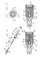
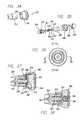
- a needleless injection system 50includes an injector device 52 and a fluid transfer device 54 .
- Injector device 52 and fluid transfer device 54are configured to mate with each other ( FIGS. 1 , 4 and 5 ).
- fluid transfer device 54contains an injectable fluid 56 , such as an aqueous diluent, e.g., a saline solution, and another material 58 , such as a lyophilized material, separate from the injectable fluid ( FIG. 5 ).
- injector device 52which contains a multi-component charge system, is configured to receive injectable fluid 56 and material 58 from fluid transfer device 54 , and to inject mixed fluid and material to a subject, e.g., a human.
- Fluid transfer device 54is generally configured to house one or more injectable materials, e.g., fluid 56 and material 58 .
- device 54includes a vial 60 , here, a cylindrical tube made of a material that is stable and substantially inert to fluid 56 and material 58 for extended periods of time, e.g., over the shelf life of the injectable material.
- the material for vial 60is relatively rigid and relatively impervious to diffusion and evaporation, such that, for example, fluid 56 does not leach out of the vial.
- Materialsinclude, for example, those that are FDA-approved and/or those used for pharmacological purposes, such a glass, polymers, and metal-containing materials.
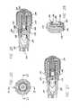
- vial 60contains therein four stoppers that define separate cavities for fluid 56 and material 58 .
- vial 60includes a top stopper 62 , a first middle stopper 64 , a second middle stopper 66 , and a bottom stopper 68 located at the bottom or distal end of the vial.
- Top stopper 62includes a centrally positioned top needle 70 . e.g., a stainless steel or relatively hard plastic needle, and a pierceable portion 72 adjacent to the bottom or distal end of the top needle.
- top needle 70is configured to engage with an orifice of injector device 52 (described below).
- First and second middle stoppers 64 and 66are connected together by a middle needle 74 .
- middle needle 74is secured to second middle stopper 66 ; and at its proximal end, the middle needle is adjacent to a piercable portion 76 of the first middle stopper 64 .
- Bottom stopper 68seals the distal end of vial 60 and is configured to engage with a pushrod (described below).
- top stopper 62 and first middle stopper 64define a first cavity that houses material 58 ; and second middle stopper 66 and bottom stopper 68 define a separate second cavity that houses fluid 56 .
- stoppers 62 , 64 , 66 , and 68can be made of any material that can provide a good seal, e.g., a liquid-tight and/or air-tight seal, with vial 60 .
- a suitable stopper materialis a resilient material such as butylene rubber.
- the stoppersshould be movable within vial 60 while still providing a good seal with the vial.
- stoppers 62 , 64 , 66 , and 68can be made of the same material or different materials.
- Fluid transfer device 54further includes an adaptor 78 and a base 80 .
- Adaptor 78is configured to receive and to secure the proximal end of vial 60 so that fluid transfer device 54 can engage with injector device 52 .
- Adaptor 78can include one or more tangs 82 that enhance connection to and release from injector device 52 .
- Base 80is configured to receive the distal or bottom end of vial 60 .
- Base 80includes an integrally formed pushrod 84 that can engage with bottom stopper 68 during use (described below).
- a fluid transfer devicemay include only two stoppers that define a cavity for a fluid only, as described in U.S. Ser. No. 60/250,573.
- a fluid transfer devicemay include a material housed in a stopper and scaled in a powder pack, as described in U.S. Ser. No. 60/250,410. Combinations of such embodiments can be used.
- Injector device 52is generally configured, to receive injectable material (fluid 56 and material 58 ) transferred from fluid transfer device 54 and to deliver the material to a subject. As described below, numerous embodiments of injector device 52 are possible.
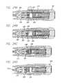
- ah injector device 100includes a multi-component charge that is activated electrically, here, with a two-lead design.
- Injector device 100generally includes, starting distally, an injector 102 , an injector cap 104 , and a battery cap 106 located proximally.
- Injector 102 , injector cap 104 , and battery cap 106are attached coaxially by threaded connections 108 and 110 .
- Injector 102defines a chamber 112 , here, a generally elongated cylindrical cavity, that receives injectable material, and an orifice 114 (in fluid communication with chamber 112 ) through which the injectable material is delivered to the chamber and expelled during use.
- Orifice 114is generally configured for needleless injection.
- Injector 102is generally made of a material that is more break-resistant than the material of vial 60 .
- the material of injector 102is resistant to mechanical shock from discharge of the charge, e.g., the injector material has a burst strength greater than the pressure generated by the charge (as described below).
- the material of injector 102preferably fails non-catastrophically, e.g., does not shatter, if exposed to sufficient mechanical shock.
- Suitable materials for injector 102include, for example, polycarbonates and polysulfones.
- device 100Inside injector 102 and injector cap 104 , device 100 includes a piston 116 , a charge sleeve 118 , and a charge cup 120 .
- piston 116 and charge sleeve 118are slidably movable within injector 102
- charge cup 120is fixedly secured between the injector and injector cap 104 ( FIGS. 12 and 13 ).
- Piston 116includes an O-ring 122 and a backup ring 124 that provide a tight, but movable, seal between the piston and the wall of chamber 112 .
- charge cup 120includes an O-ring 126 and a backup ring 128 that, provide a tight seal between the charge cup and charge sleeve 118 , while still allowing the charge sleeve to slide within injector 102 .
- Charge-cup 120further defines a charge cavity 130 in which the charge is placed. After the charge is loaded in cavity 130 , the charge is covered and sealed with a burst membrane 132 and covered with a nozzle 134 .
- Burst membrane 132can be, for example, a 0.005 inch thick disc of Mylar® foil.
- Nozzle 134which fits over a portion of charge cup 120 , is a cylindrical cup having an opening at its base.
- Nozzle 134provides a good interference fit between charge cup 120 and charge sleeve 118 , and can also minimize any bulging of the charge cup near cavity 130 due to packing of the charge in the cavity.
- Piston 116 and charge cup 120can be made of, e.g., injection molded polymer such as polycarbonate.
- Nozzle 134 and charge sleeve 118can be made of, e.g., stainless steel.
- the chargeincludes a mixture of a propellant (e.g., 1:1 copper oxide and 5-aminotetrazole, or 5AT) and a triggering material (e.g., sucrose and potassium chlorate).
- a propellante.g., 1:1 copper oxide and 5-aminotetrazole, or 5AT
- a triggering materiale.g., sucrose and potassium chlorate
- specific compositions for charge systemsare determined empirically, taking into account, for example, the size of the injector, the amount of injectable material to be delivered, and the size of the orifice.
- a non-limiting, illustrative list of examples of chemical components that can be usedare disclosed in U.S. Pat. Nos.
- injector device 100electrically activates or ignites the charge.
- Charge cup 120further includes two wire leads 136 connectable to an electrical energy source. Leads 136 extend from cavity 130 (and the charge) to an energy source, here, a battery 138 .
- Battery 138e.g., a lithium coin battery, is secured between injector cap 104 and battery cap 106 .
- Battery 138is nested in an electrically-conducting-contact can 140 along with a cushion disc 142 made of a resilient material.
- Contact can 140has a rim configured to contact one terminal of battery 138 , and an opening 144 that allows one of leads 136 to contact another terminal of the battery.
- Cushion disc 142can minimize recoil during use of injector device 100 and allows battery 138 to be depressed to contact one of the leads 136 (described below).
- leads 136at their distal ends, the leads terminate near charge cavity 130 .
- Leads 136can terminate anywhere along the longitudinal length of cavity 130 , depending on which part of the charge is to be exposed to activation or ignition.
- the distal ends or portions of leads 136are electrically connected together, e.g., by a tungsten filament (not shown) that extends across cavity 130 , e.g., transverse to the longitudinal length of the cavity.
- the surface of cavity 130can be coated with an electrically-conducting layer, and the distal portions of leads 136 can be electrically connected together via the electrically-conducting layer.
- injectable materiali.e., fluid 56 and material 58
- injector device 100the system and the device are separated; and the injectable material is ejected from the injector device.
- injector 102 and adaptor 78are connected together, e.g., snap fit together.
- Orifice 114 and top needle 70are engaged in fluid communication with each other.
- the injector deviceWith fluid transfer device 54 and injector device 100 connected, the injector device is pushed down or distally, with base 80 stationary, e.g., against a fixed, flat surface. As pressure develops in vial 60 to a sufficient or predetermined level, top needle 70 pierces pierceable portion 72 , and middle needle 74 pierces pierceable portion 76 . As injector device 100 is pushed down, pushrod 84 advances bottom stopper 68 up. As injector device 100 is continued to be pushed down, fluid 56 is transferred through middle needle 74 to the cavity between top stopper 62 and first middle stopper 64 where the fluid mixes with material 58 . The mixed material is transferred through top needle 70 , through orifice 114 , and into chamber 112 . Injector device 100 is advanced down until a predetermined amount of fluid 56 , material 58 , and/or mixed material are transferred to the injector device at which time the injector device is disconnected from fluid transfer device 54 .
- orifice 114is placed adjacent to a predetermined injection site, and battery 138 is pushed distally or down. As battery 138 is pushed down, one of its terminals contacts the spaced proximal end of one of the leads 136 ( FIG. 12 ), thereby completing an electrical loop between the leads 136 (since the other lead is already connected to the other terminal of the battery via contact can 140 ). Electrical energy from battery 138 flows through the filament extending across the charge, and ignites the charge. The activated or ignited charge generates gas, i.e., pressure, in cavity 130 . The gas ruptures burst membrane 132 at a predetermined pressure and propels charge sleeve 188 and piston 116 distally, thereby pushing the injectable material through orifice 114 and into the injection site.
- gasi.e., pressure
- FIGS. 14-16show another embodiment of an injector device 150 , in which elements similar to elements described above are designated with the same reference characters.
- Injector device 150includes a separate cup 152 for housing the charge and a modified arrangement of wire leads. Cup 152 further minimizes any bulging of charge cup 120 due to packing of the charge. Cub 152 allows the charge to be prepared separately from charge cup 120 . Cup 152 also allows the charge to be prepared modularly, e.g., like tailorable bullet modules that can be loaded into predetermined injector devices according to medication, dosage, delivery rate, etc.
- cup 152includes two slots 154 and two grooves 156 .
- Slots 154are configured to receive a wire or a filament (not shown) that extends across the longitudinal length of cup 152 and through the charge.
- the wiree.g., a tungsten filament
- the wirecan be secured to cup 152 with an electrically-conducting material, such as an electrically-conducting epoxy.
- Slots 154are also designed so that the wire or filament can be relatively easily threaded and attached to cup 152 .
- Grooves 156extend along the side of cup 152 and to the bottom of the cup ( FIG. 15 ).
- Grooves 156 and the top surface or rim 160 of cup 152are coated with an electrically-conducting layer, e.g., a metal layer, such that the layer can electrically contact the wire or filament.
- electrically-conducting material in one of the grooves 156 at the bottom of cup 152is in electrical communication with electrically-conducting material in another one of the grooves at the bottom of the cup via the grooves on the side of the cup, rim 160 , and the wire or filament.
- cup 152can have more than two slots 154 and/or grooves 156 that can be arranged in different arrangements, e.g., asymmetrically arranged around the cup.
- injector device 150further includes two wire leads 158 .
- one of the leads 158electrically contacts electrically-conducting material formed in one of the grooves 156 at the bottom of cup 152
- the other leadcontacts electrically-conducting material formed in the other groove 156 at the bottom of the cup.
- one of the leads 158contacts contact can 140
- the other leadis spaced from battery 138 , as described above.
- injectable materialis transferred to injector device 150 and ejected from the device as generally described above.
- FIGS. 18-20show another embodiment of an injector device 170 , in which elements similar to elements described above are designated with the same reference characters.
- Injector device 170is generally similar to injector device 100 , but modified to include one center lead 172 instead of two leads 136 .
- lead 172contacts a terminal of a battery assembly 174 , here, two lithium coin batteries.
- lead 172extends through cavity 130 , and a distal portion of the lead is crimped to an electrically-conducting filament 176 by an electrically-conducting tube 178 .
- Filament 176extends through the charge in cavity 130 , between burst membrane 132 and the distal end of charge cup 120 , and between the charge cup and nozzle 134 where the filament contacts a contact strip 180 .
- Contact strip 180also contacts charge sleeve 118 .
- Electrical contactis continued from contact strip 180 to a second contact strip 182 , for example, by making charge sleeve 118 out of an electrically-conducting material such as stainless steel or by connecting the contact strips with a filament.
- Second contact strip 182is capable of contacting a second terminal of battery assembly 174 .
- second contact strip 182can be connected to contact can 140 , e.g., by a filament, and the contact can may have a portion that is spaced from, but capable of contacting, the second terminal of battery assembly 174 .
- the portioncan be contacted with the second terminal, e.g., by depressing a button 184 and cushion disk 142 .
- Device 170can be triggered by depressing button 184 , which completes an electrical loop to ignite the charge.
- FIGS. 21 , 22 A, 22 B, and 23show another embodiment of an injection system 200 wherein a fluid transfer device is integrated with an injector device. Elements similar to elements described above are designated with the same reference characters.
- System 200includes an injector 202 , an injector cap 204 , and a removable safety band 206 .
- Injector 202defines a chamber 210 and an orifice 212 , as generally described above.
- chamber 210contains an injectable material, such as a lyophilized material.
- chamber 210is empty.
- Injector 202 and injector cap 204are movable, relative to one another by a threaded connection 208 when safety band 206 is removed from system 200 , e.g., by a user.
- system 200includes a piston 214 , a vial 216 , and a charge cup 218 .
- Piston 214includes an O-ring 220 and a backup ring 222 , as generally described above.
- Piston 214defines a lumen 224 that extends transverse to the length of the piston, and an annular tab 225 .
- Tab 225engages a portion of injector 202 to keep piston 214 stationary when fluid is transferred through the piston (described below).
- Tab 225is also configured to separate, e.g., shear, from piston 214 under a predetermined force, e.g., a force of injection.
- a piercing element 226Disposed within piston 214 is a piercing element 226 , e.g., a hollow needle, that is in fluid communication with lumen 224 and extends proximally where it engages a stopper seal 227 .
- Stopper seal 227seals the proximal end of piercing element 226 .
- stopper seal 227can be used with piston 214 to seal the chamber to protect the material from exposure, e.g., to air.
- Orifice 212can be sealed with a removable barrier.
- Vial 216e.g., a glass vial as described above, is coaxially positioned within injector 202 .
- Distal stopper 228e.g., made of a biocompatible or inert material, such a butyl rubber, includes a pierceable portion 234 adjacent to stopper seal 227 .
- Proximal stopper 230includes an outer portion 229 and an inner core 231 . In some embodiments, outer portion 229 and inner core 231 are formed of different materials.
- outer portion 229can be formed of a material, e.g., a butyl rubber, that is relatively inert to fluid 232 and provides a tight seal with vial 216 ; and core 231 can be formed of a relatively rigid material having a relatively high durometer. Core 231 can provide system 200 with predictable injections, e.g., by minimizing undesirable harmonics during injection.
- Charge head 218including embodiments for igniting the charge, can be any of the embodiments described above and below, for example, as in injector device 100 , 150 , or 170 .
- FIGS. 24A-24Dshow one embodiment of a method of using injection system 200 .
- Safety band 206is removed to allow injector cap 204 to be rotated to advance the injector cap toward orifice 212 , i.e., distally.
- distal and proximal stoppers 228 and 230are also forced distally such that piercing element 226 pierces stopper seal 227 and portion 234 of the distal stopper ( FIG. 24B ).
- Tab 225keeps piston 214 generally stationary.
- fluid 232is transferred from between stoppers 228 and 230 , through piercing element 226 , through lumen 224 , and into chamber 210 , where, in some embodiments, the fluid mixes with another material, e.g., a lyophilized material.
- Injector cap 204is advanced distally until all of fluid 232 is transferred into chamber 210 ( FIG. 24C ).
- Distal stopper 228mates with piston 214 .
- Injectable materiali.e., fluid 232 or fluid mixed with another material, is expelled through orifice 212 by triggering charge head 218 as described above.
- Triggering the charge headpropels the charge sleeve distally, which propels stoppers 228 and 230 and piston 214 distally (and shears tab 225 ), thereby expelling the injectable material through orifice 212 ( FIG. 24D ).
- proximal stopper 230can be made of one material, e.g., integrally formed of one material.
- Distal stopper 288can be formed of multiple materials, as described above for stopper 230 .
- stopper seal 227 and distal stopper 228can be integrally formed as one component.
- stopper seal 227 and stopper 228can be formed of the same or different materials.
- piston 214 and piercing element 226can be integrally formed.
- piston 214can define a proximal piercing portion capable of piercing stopper seal 227 and distal stopper 228 .
- the proximal piercing portionis capable of establishing fluid communication between lumen 224 and material 232 .
- Other configurations of lumen 224are possible to transfer material 232 from one end of piston 214 to another end.
- FIGS. 25-29show another embodiment of an injector device 250 in which the charge is ignited non-electrically, here, chemically.
- Device 250includes an injector 252 , an injector cap 254 connected to the injector by a threaded connection 258 , and a safety cap 256 .
- Injector 252defines an orifice 260 and a chamber 262 for injectable material, generally as described above.
- device 250includes a piston 264 and a charge cup 266 .
- Piston 264includes a piston O-ring 268 and a piston backup ring 270 ; and charge cup 266 includes a charge cup O-ring 272 and a backup ring 274 , as generally described above.
- Charge cup 266defines a charge cavity 282 , a breakable capsule 284 , and a burst membrane 286 .
- charge cavity 282contains a charge
- capsule 284contains a material capable of activating or igniting the charge, e.g., a catalyst or an oxidizing agent such as sulfuric acid.
- device 250further includes a shear pin 276 , a movable charge sleeve 278 , and a nozzle 280 .
- Shear pin 276holds charge sleeve 278 stationary at an initial position until a predetermined pressure is generated by the charge.
- Charge sleeve 278includes a projection 288 that abuts against burst membrane 286 and capsule 284 ( FIG. 28 ).
- Device 250also includes a gasket 294 that, during use, minimizes recoil and allows safety cap 256 to be advanced distally (described below).
- Safety cap 256includes a removable safety tab 292 , e.g., a strip of plastic. Safety cap 256 is attached to device 250 by a threaded connection 290 defined by the proximal end of charge cup 266 .
- device 250is fired by removing safety tab 292 from the device, which allows safety cap 256 to be pushed distally, toward orifice 260 , which is abutted against a surface, e.g., a subject's skin.
- the activating materialreacts with the charge in cavity 282 and generates pressure.
- the pressureincreases inside cavity 282 until burst membrane 286 ruptures and the force against charge sleeve 278 is sufficient to break shear pin 276 .
- This pressuremoves sleeve 278 distally, thereby pushing piston 264 distally and expelling injectable material in chamber 262 through orifice 260 .
- FIGS. 34-38show another embodiment of an injection system 350 including an injector device 352 and a power unit 354 .
- Injector device 352can be disposable, and power unit 354 can be reusable.
- injector device 352includes an injector 356 and an injector cap 358 connectable to the injector by a threaded connection and sealable with a face seal 361 , e.g., an O-ring.
- injector 356defines a cavity 359 and an orifice 362 , as generally described above.
- injector device 352includes a piston 360 , an electrically-conductive bridge 364 that engages the proximal end of the piston, and a membrane 367 , e.g., a disc of paper, between the piston and injector cap 358 .
- Piston 360includes O-rings 368 and backup rings 370 , and defines a charge cavity 366 at the proximal end, as generally described herein. That is, charge cavity 366 is integrally formed with piston 360 .
- Bridge 364includes two conductive members 372 that fit into two grooves 374 defined by piston 360 .
- a wire 376e.g., a tungsten filament, extends from one member 372 , through a charge in cavity 366 , and to the other member 372 .
- Injector device 352further includes two electrically-conductive leads 378 that extend from members 372 and through injector 356 to contact power unit 354 .
- Power unit 354includes an adaptor 380 , a battery 382 , and a switch 384 .
- Adaptor 380is configured to connect to injector device 352 and to trigger the injector device. Numerous embodiments are possible.
- adaptor 380includes two extensions 386 that engage with injector device 352 ( FIG. 34 ). Each extension 386 has a conductive lead 388 therein that extends from lead 378 to battery 382 , where the leads are capable of contacting a terminal of the battery.
- Switch 384is configured to selectably connect the terminals of battery 382 to leads 388 , thereby passing a current through the leads.
- a springcan be placed between injector cap 358 and battery 352 to push battery proximally and by depressing switch 384 distally, the terminals of the battery can be urged distally into contact with leads 388 .
- switch 384Other embodiments of switch 384 are possible.
- an injectable material(not shown) is placed cavity 359 , and orifice 362 is placed adjacent to an injection site.
- Switch 384is then activated such that an electrical current flows from battery 382 and through leads 388 , leads 378 , members 372 , and filament 376 .
- the current flowing through filament 376ignites the charge in cavity 366 .
- the ignited chargegenerates pressure as described herein and propels piston 360 distally, thereby ejecting the injectable material out of cavity 359 , through orifice 362 , and info the injection site.
- injection device 352can be disconnected from power unit 354 , and another injection device can be connected to the power unit.
- injector devicesare possible and are described in incorporated-by-reference U.S. Provisional Patent Application Ser. Nos. 60/250,410; 60/250,425; 60/250,537; and 60/250,573.
- the injectable materialcan include one or more substances.
- the second substancecan be a liquid, e.g., a diluent or solute.
- Such liquidscan include buffers, inert fillers, pharmaceutically acceptable-carriers, or the like.
- the substancecan be a dry substance, e.g., a lyophilized protein, nucleic acid, e.g., RNA or DNA, or polysaccharide.
- the substancecan be a vaccine, or a drug.
- the substancecan be a peptide, polypeptide, or protein, e.g., an antibody, an enzyme, a hormone or growth factor.
- Preferred substancesinclude insulin.
- the substancecan be: a blood protein, e.g., clotting factor VIII or a IX, complement factor or component; a hormone, e.g., insulin, growth hormone, thyroid hormone, a catecholamine, a gonadotrophin, PMSG, a trophic hormone, prolactin, oxytocin, dopamine and the like; a growth factor, e.g., EGF, PDGF, NGF, IGF's and the like; a cytokine, e.g., an, interleukin, CSF, GMCSF, TNF, TGF-alpha, TGF-beta, and the 25 like; an enzyme, e.g., tissue plasminogen activator, streptokinase, cholesterol biosynthetic or degradative, glycosolases, and the like; a binding protein, e.g., a steroid binding protein, a growth hormone or growth factor binding protein and the like; an immune system protein, e.g
- the subjectcan be a human or an animal, e.g., a laboratory animal, or pet, e.g., a dog or cat, or other animal, e.g., a bovine, a swine, a goat, or a horse.
- a human or an animale.g., a laboratory animal, or pet, e.g., a dog or cat, or other animal, e.g., a bovine, a swine, a goat, or a horse.
- Therapeutic agents that can be used in the devices and methods described hereininclude, for example, vaccines, chemotherapy agents, pain relief agents, dialysis-related agents, blood thinning agents, and compounds (e.g., monoclonal compounds) that can be targeted to carry compounds that can kill cancer cells.
- examples of such agentsinclude, insulin, heparin, morphine, interferon, EPO, vaccines towards tumors, and vaccines towards infectious diseases.
- the devicecan be used to deliver a therapeutic agent to any primate, including human and non-human primates.
- the devicecan be used to deliver an agent, e.g., a therapeutic agent to an animal, e.g., a farm animal (such as a horse, cow, sheep, goat, or pig), to a laboratory animal (such as a mouse, rat, guinea pig or other rodent), or to a domesticated animal (such as a dog or cat).
- the animal to which the therapeutic agent is being deliveredcan have any ailment (e.g., cancer or diabetes). It is expected that the device may be most useful in treating chronic conditions.
- the devicecan also be used to deliver a therapeutic agent (such as a vaccine) to an animal that is not suffering from an ailment (or that is suffering from an ailment unrelated to that associated with the therapeutic agent). That is, the device can be used to deliver therapeutic agents prophylactically.
- a therapeutic agentsuch as a vaccine
- the devices and methods of the inventioncan be used to individually tailor the dosage of a therapeutic agent to a patient.
- the devices and methods of the inventioncan allow for outpatient treatment with increased convenience, such as, for example, without the use of an I.V.
- Devices and methods described hereincan be advantageous because they can be used to promote maintenance of the concentration of a therapeutic agent in a patient's plasma within a safe and effective range. Moreover, the device can release therapeutic agents in response to the concentration of an analyte in the patient's system. Thus, the rate of drug delivery can be appropriate for the patients physiological state as it changes, e.g., from moment to moment.
- the chargeis formed of at least two discrete materials (e.g., at least two discrete materials, at least three discrete materials, at least four discrete materials, at least five discrete materials, at least six discrete materials, at least seven discrete materials, at least eight discrete materials, at least nine discrete materials, at least 10 discrete materials, at least 11 discrete materials, at least 12 discrete materials, at least 13 discrete materials, at least 14 discrete materials, at least 15 discrete materials, at least 16 discrete materials, at least 17 discrete materials, at least 18 discrete materials, at least 19 discrete materials, at least 20 discrete materials) formed as separate components.
- the discrete materialsare typically used in combination to provide a desired pressure profile of the injectable fluid ejected by an injection device.
- Each discrete materialcan be formed of a single material or a combination of materials.
- the chargecan propel, e.g., a piston with a predetermined pressure profile, i.e., pressure as a function of time. Accordingly, the piston can inject the injectable material from an injector with the predetermined pressure profile capable of injecting the injectable material effectively.
- the types of discrete materials used in a chargecan include, for example, one or more triggers (a discrete material capable of generating relatively large amounts of gas and heat), one or more propellants (a relatively slow burning material) and/or one or more passive decay materials (a low-yielding material that continues the burn of the charge but which does not add a substantial amount of heat or kinetic effect).
- triggersa discrete material capable of generating relatively large amounts of gas and heat
- propellantsa relatively slow burning material
- passive decay materialsa low-yielding material that continues the burn of the charge but which does not add a substantial amount of heat or kinetic effect.
- a chargecan have one or more propellants disposed between one or more triggers and one or more passive decay materials.
- a chargecan have one or more triggers disposed between one or more propellants and one or more passive decay materials.
- a chargecan have one or more passive decay materials disposed between one or more triggers and one or more propellants.
- one or more propellantscan be intercalated with one or more triggers and/or one or more passive decay materials. Combinations of these exemplary embodiments can be used.
- a chargeincludes two or more discrete pyrotechnic materials that can react and deflagrate.
- Each pyrotechnic materialcan be formed of a single material or a combination of materials. Deflagrations can proceed at any desired rate (e.g., several inches per second, several hundred feet per second). Examples of reactions that undergo deflagrations include those used in airbag chemistry and rocket motor chemistry.
- the chargeis designed so that if is capable of generating pressure such that the injectable material can be ejected by an injection device with sufficient force to create an opening in the body (e.g., an opening in the skin of the body) through which the injectable material can be injected ( FIG. 30 ).
- the openingcan created, for example, relatively quickly and acceptably small to minimize pain and discomfort to the body.
- the triggercan be capable of generating a relatively high initial pressure, such as about 4,000 psi, in a relatively short amount of time, such as about 1-5 msec, e.g., 1-2.5 msec.
- the pressure profile of the triggercan have duration or latency of, for example, about 15 msec, with a filial pressure of about 500 psi.
- the chargecan be capable of generating sufficient pressure such that the injectable material can continue to keep the opening open so that the injectable material can be delivered through the opening at a desired dose, for a desired period of time and/or to a desired depth (e.g., cutaneous, subcutaneous, intramuscular, etc.) ( FIG. 31 ).
- the chargecan generate relatively large amounts of gas but relatively low amounts of heat.
- the pressure generated by the chargedoes not enlarge the opening that can cause discomfort, and/or allow the opening to decrease in size, which can decrease the effectiveness of the injection by allowing the injectable material to leak back out of the opening.
- the chargeis capable of generating a relatively low initial and final pressures, such as about 700-800 psi and 200-300 psi, respectively.
- the latency of the pressure profile of the chargecan be relatively large, such as about 500 msec.
- the chargecan generate a pressure profile that is a combination of the pressure profiles of the trigger, the propellant, and/or the passive decay material, and which can effectively deliver the injectable material ( FIG. 32 ).
- FIG. 33shows an example of a charge having three components loaded in a charge cup or cavity 300 .
- the chargehas an igniter 302 (e.g., 75 mg of BKNO 3 ), a passive decay material 304 (e.g., 60 mg of gum arabic), and a propellant 306 (e.g., 120 mg of CuO/5 aminotetrazole).
- the sequence of the pyrotechnic materialscan be adjusted according to the pressure profile desired, e.g., igniter/propellant/igniter. Similarly, the quantities of the pyrotechnic materials can be adjusted.
- charge cup 300has a burst membrane 308 that acts a pressure dam so that a predetermined pressure can build up in the charge cup before the membrane ruptures and pressure is released to propel, e.g., the charge sleeve and piston.
- the memberscan be replaced with, for example, a shear pin.
- a usercan trigger the charge by passing a current through a filament, which can extend through the igniter. Triggering the charge causes the igniter to burn first, followed by the decay material, and then the propellant.
- the chargeis capable of providing a multi-stage reaction that can deliver the injectable material with a desired pressure profile.
- the desired, pressure profilecan also be controlled by tuning or shaping the charge and/or the pyrotechnic materials.
- the chargecan be shaped by changing the shape of the charge cup or cavity.
- the charge cup or cavitycan have a narrow distal end relative to the distal end; a diverging or converging longitudinal cross section; and/or a narrowed throat region along the longitudinal axis.
- the chargecan be solid, e.g., like a cigarette, or hollow, e.g., by using a filler material.
- the pyrotechnic materialscan be formed in different shapes, such as spheres, rods, plates, etc., to change the surface area to volume ratio, thereby affecting the burn rate and providing different burning characteristics.
- the pyrotechnic materialscan be granular or pelletized.
- the chargecan be combination of solid materials for two or more stages that includes BKNO 3 and CuO/5 aminotetrazole; thermite—aluminum powder and FeO 2 ; sulfur/chlorate mixtures; aluminum powders and potassium chlorateor potassium perchlorate; urazole and KClO 4 ; or urazole and KNO 3 .
- chargesinclude a system having solid and liquid materials. Examples include vinegar and sodium bicarbonate; NaMnO 4 (permanganate) and hydrogen peroxide; Na metal and water; Li metal and water; and quick lime and water.
- This systemcan also be used as a percussive detonator in which the NaMnO 4 is used to catalyze the rapid breakdown of hydrogen peroxide if greater than 70%.
- Establishing first and second stages for a chargecould be implemented by physical segmentation of two reaction chambers, or in having a more soluble outer zone of solid reactant, and an inner zone of less soluble phase to slow the reaction. This can be accomplished by compounding and pelletizing.
- chargesinclude a system having liquid-liquid materials. While sometimes referred to as hypergolic, or hypergol fuels, these systems could be packaged in separate containers. When the containers are physically breached, they react quickly. Examples include monomethyl hydrazine and nitrogen tetra oxide, Aerozine-50, and Competitive Impulse; Non-Carcinogenic Hypergol or CINCH, which can be an all-purpose replacement for a wide variety of hydrazine and hydrazine-based fuels.
- first-fire compositionincludes a mixture, such as 50/50, of the ignition mix and the material that it is intended to ignite.
- Examples of granular or pelletized igniter compositionsare: BKNO 3 (Boron/Potassium Nitrate); ALCLO (Aluminum/Potassium Perchlorate); MAG-TEF (Magnesium/Teflon); MTV (Magnesium/Teflon/Viton); BP (Black Powder).
- igniter compositions utilized in “first-fire” mixesare: A1A (Iron Oxide/Diatomaceous Earth/Zirconium; ZPPV (Zirconium/Potassium Perchlorate/Viton); TiCuO (Titanium/Copper Oxide); BBC (Boron/Barium Chromate); BCC (Boron/Calcium Chromate); BBCTiPP (Boron/Barium Chromate/Titanium/Potassium Perchlorate).
- the charges described hereincan be used in any injection system (e.g., any needleless injector) properly configured to house such charges (e.g., having an appropriate charge cup or cavity).
- a chargeincludes a propellant material, here; 5-AT, and a trigger material, here, a mixture of KClO 3 and sucrose.
- the chargeis placed in a closed finite volume, such as a charge cavity.
- the propellant material (5-AT)is placed on the bottom of the charge cavity, and the trigger material is placed on the propellant material.
- the propellant and/or trigger materialcan be compacted, e.g., about 50-250 psi, or minimally packed.
- the trigger materialcan be activated, for example, by passing, a current through a wire filament or using concentrated sulfuric acid.
- One or more other materialssuch as a passive decay materials (e.g., gum arabic) or a heat generating material (e.g., B/KNO 3 ) can be placed between the propellant and the trigger materials, depending on the desired pressure profile.
- FIG. 39shows a pressure profile (pressure as a function of time) capable of providing a needleless injection, e.g., with minimized discomfort.
- the pressure profilewas produced by a charge of 50 mg of 5 AT, compacted under 200 psi, and 33 mg of a mixture of KClO 3 and sucrose (22 mg KClO 3 and 11 mg of sucrose) over the 5AT.
- the charge cavityhad a diameter of about 3/16 inch.
- the depthi.e., the distance between the open distal end of the charge cavity and distal end of the charge, was about 0.191 inch.
- the pressure profilegenerally increases rapidly, e.g., over about 2-3 msec, to a peak pressure 511 .
- the pressurethen decreases to a tail pressure 513 .
- the peak pressurecan decrease to the tail pressure relatively flatly to produce a plateau region 515 with a plateau pressure.
- the peak pressurecan decrease relatively sharply, e.g., approximately exponential. It is believed that the peak pressure creates an opening, e.g., in the subject, through which injectable material can be delivered, and the plateau pressure maintains the opening so that injectable material can be continued to be delivered, e.g., without the opening closing and injectable material leaking back.
- the pressure profileis a function of one or more parameters or variables. By adjusting these parameters or variables, the pressure profile can be adjusted to provide a desired pressure profile. For example, the pressure profile can be adjusted to inject subjects with different tissue structure, to inject different types of tissue on a subject, or to inject different types of injectable materials.
- Some of these variablesinclude the amounts of components e.g., the trigger or the propellant material, that form the charge; the compositions of the components of the charge, the degree of compaction of the components in the charge, cavity, e.g., the apparent density of the components; the depth; and the void volume of the charge cavity.
- the void volumeis approximately equal to the difference between the volume of the charge cavity and the total volume of the components of the charge.
- the void volumeis the empty volume between the trigger material and the distal end of the charge cavity, e.g., where the burst membrane is positioned.
- the amount of trigger materialis proportional to the peak pressure and the tail pressure. For example, increasing the amount of trigger material can increase the peaks pressure and the tail pressure.
- the amount of propellant materials related to the plateau pressure and the tail-pressureFor example, increasing the amount of propellant material, such as 5 AT, increases the plateau pressure and the tail pressure.
- the degree of compactionaffects the shapes of the pressure profile curve. High compaction can produce a plateau-shaped curve. Low or minimal compaction can produce a curve that is not plateau-shaped, e.g., one that decreases in an exponential-like manner.
- FIG. 40shows a pressure profile for a charge having 50 mg of 5-AT (compacted by hand packing) and 39 mg of a trigger mixture (26 mg of KClO 3 and 13 mg of sucrose). The depth was 0.190 inch.
- hand packingi.e., lower compaction, of the propellant, and increasing the amount of trigger provides a relatively higher peak pressure (about 6125 psi to about 5000 psi).
- FIG. 41shows a pressure profile for a charge having 50 mg of 5-AT (compacted under 210 psi) and 39 mg of a trigger mixture (26 mg of KClO 3 and 13 mg of sucrose). The depth was 0.190 inch. Compared to FIG. 40 , the degree of compaction is higher. As a result, the peak pressure is lowered (about 6125 psi to about 4812 psi), but the tail pressure is increased (about 2500 psi to about 3500 psi).
- FIG. 42shows a pressure profile for a charge having 50 mg of 5-AT (compacted under 220 psi) and 39 mg of a trigger mixture (26 mg of KClO 3 and 13 mg of sucrose). The depth was 0.190 inch. Compared to FIG. 41 , the degree of compaction is higher, which increases injection time, i.e., the time it takes for the pressure profile to decrease from the peak pressure to the tail pressure.
- FIG. 43shows a pressure profile for a charge having 50 mg of 5-AT (compacted under 220 psi) and 31.5 mg of a trigger mixture (21 mg of KClO 3 and 10.5 mg of sucrose). The depth was 0.250 inch. Compared to FIG. 42 , lowering the amount of trigger material and increasing the depth, lowers the peak pressure (from about 5125 psi to about 3875 psi) and increases the injection time.
- FIG. 44shows a pressure profile for a charge having 50 mg of 5-AT (compacted under 50 psi) and 36 mg of a trigger mixture (24 mg of KClO 3 and 12 mg Of sucrose). The depth was 6.190 inch.
- increasing the amount of trigger material and decreasing the degree of compactionincreases the peak pressure (from about 5000 psi to about 5687 psi) and tail pressure (from about 2250 psi to about 2500 psi), slightly increases the injection time.
- FIG. 45shows a pressure profile for a charge having 50 mg of 5-AT (compacted under 100 psi) and 36 mg of a trigger mixture (24 mg of KClO 3 and 12 mg of sucrose). The depth was 0.190 inch. Compared to FIG. 44 , increasing the degree of compaction decreases the peak pressure (from about 5687 psi to about 4312 psi) and increases the injection time.
- FIG. 46shows a pressure profile for a charge having only 31.5 mg of a trigger mixture (21 mg of KClO 3 and 10.5 mg of sucrose). The depth was 0.070 inch. Compared to FIG. 39 , removing the propellant results in a rapid decrease from the peak pressure.
- the chargecan further include B/KNO 3 , an example of a material capable of generating high heat and low gas, between the propellant and trigger materials.
- B/KNO 3is capable of further expanding gases generated by the trigger material and increasing the combustion kinetics of the propellant.
- the B/KNO 3can increase the peak pressure, the plateau pressure, and/or the tail pressure.
- FIG. 47shows a pressure profile for a charge having 50 mg of 5-AT (compacted under 210 psi) and 39 mg of a trigger mixture (26 mg of KClO 3 and 13 mg of sucrose). The depth was 0.220 inch. 20 mg of B/KNO 3 (compacted under 40 psi) was placed between the 5-AT and the trigger mixture.
- the B/KNO 3generally provided a relatively high peak pressure (about 5562 psi), a relatively high plateau pressure (about 4875 psi), a relatively high fail pressure (about 3812 psi), and a relatively short injection time.
- FIG. 48shows a pressure profile for a charge having 50 mg of 5-AT (compacted under 220 psi) and 21 mg of a trigger mixture (14 mg of KClO 3 and 7 mg of sucrose). The depth was 0.190 inch. 20 mg of B/KNO 3 (compacted under 40 psi) was placed between the 5-AT and the trigger mixture. Compared to FIG. 47 , a decrease in depth and the amount of trigger material lower the peak pressure (from about 5562 psi to about 3812 psi) but slightly increase the slope of the plateau region.
- FIG. 49shows a pressure profile for a charge having 30 mg of 5-AT (compacted tinder 210 psi) and 36 mg of a trigger mixture (24 mg of KClO 3 and 12 mg of sucrose). The depth was 0.130 inch. 10 mg of B/KNO 3 (compacted under 40 psi) was placed between the 5-AT and the trigger mixture.
- the pressure profilehas a double peak with a relatively rapidly decreasing tail.
- the pressure profilecan be modified by modifying the depth. Modifying the depth can produce pressure profiles having both an approximately exponentially decaying region and a relatively flat plateau region.
- FIGS. 49 to 54show pressure profiles for a charge having 30 mg of 5-AT (compacted under 210 psi), 10 mg of B/KNO 3 (Compacted under 40 psi), 36 mg of a trigger material mixture (24 mg of KClO 3 and 12 mg of sucrose).
- the depthwas 0.130 inch; in FIG. 50 , the depth was 0.135 inch; in FIG. 51 the depth was 0.145 inch; in FIG. 52 , the depth was 0.155 inch; in FIG. 53 , the depth was 0.165 inch; and in FIG. 54 , the depth was 0.175 inch. Controlling the depth can change the shape of the pressure profile, e.g., whether the profile has a rapidly charging portion and/or a relatively flat portion.
- a pressure profilecan be modified e.g., tailored, in whole or in part, by modifying one or more of the variables described above.
Landscapes
- Health & Medical Sciences (AREA)
- Vascular Medicine (AREA)
- Engineering & Computer Science (AREA)
- Anesthesiology (AREA)
- Biomedical Technology (AREA)
- Heart & Thoracic Surgery (AREA)
- Hematology (AREA)
- Life Sciences & Earth Sciences (AREA)
- Animal Behavior & Ethology (AREA)
- General Health & Medical Sciences (AREA)
- Public Health (AREA)
- Veterinary Medicine (AREA)
- Infusion, Injection, And Reservoir Apparatuses (AREA)
- Silver Salt Photography Or Processing Solution Therefor (AREA)
- Injection Moulding Of Plastics Or The Like (AREA)
Abstract
Description
Claims (16)
Priority Applications (1)
| Application Number | Priority Date | Filing Date | Title |
|---|---|---|---|
| US13/053,024US8500681B2 (en) | 2000-11-30 | 2011-03-21 | Injection systems |
Applications Claiming Priority (6)
| Application Number | Priority Date | Filing Date | Title |
|---|---|---|---|
| US25053700P | 2000-11-30 | 2000-11-30 | |
| US25057300P | 2000-11-30 | 2000-11-30 | |
| US25042500P | 2000-11-30 | 2000-11-30 | |
| US25041000P | 2000-11-30 | 2000-11-30 | |
| US10/001,002US7931614B2 (en) | 2000-11-30 | 2001-11-30 | Injection systems |
| US13/053,024US8500681B2 (en) | 2000-11-30 | 2011-03-21 | Injection systems |
Related Parent Applications (1)
| Application Number | Title | Priority Date | Filing Date |
|---|---|---|---|
| US10/001,002ContinuationUS7931614B2 (en) | 2000-11-30 | 2001-11-30 | Injection systems |
Publications (2)
| Publication Number | Publication Date |
|---|---|
| US20110172634A1 US20110172634A1 (en) | 2011-07-14 |
| US8500681B2true US8500681B2 (en) | 2013-08-06 |
Family
ID=27500354
Family Applications (4)
| Application Number | Title | Priority Date | Filing Date |
|---|---|---|---|
| US10/007,061Expired - Fee RelatedUS7150409B2 (en) | 2000-11-30 | 2001-11-30 | Injection systems |
| US10/001,002Expired - Fee RelatedUS7931614B2 (en) | 2000-11-30 | 2001-11-30 | Injection systems |
| US09/999,549AbandonedUS20020156418A1 (en) | 2000-11-30 | 2001-11-30 | Injection systems |
| US13/053,024Expired - Fee RelatedUS8500681B2 (en) | 2000-11-30 | 2011-03-21 | Injection systems |
Family Applications Before (3)
| Application Number | Title | Priority Date | Filing Date |
|---|---|---|---|
| US10/007,061Expired - Fee RelatedUS7150409B2 (en) | 2000-11-30 | 2001-11-30 | Injection systems |
| US10/001,002Expired - Fee RelatedUS7931614B2 (en) | 2000-11-30 | 2001-11-30 | Injection systems |
| US09/999,549AbandonedUS20020156418A1 (en) | 2000-11-30 | 2001-11-30 | Injection systems |
Country Status (6)
| Country | Link |
|---|---|
| US (4) | US7150409B2 (en) |
| EP (1) | EP1339442A4 (en) |
| JP (4) | JP4434583B2 (en) |
| KR (1) | KR20030071780A (en) |
| CA (1) | CA2430499C (en) |
| WO (1) | WO2002051470A2 (en) |
Cited By (6)
| Publication number | Priority date | Publication date | Assignee | Title |
|---|---|---|---|---|
| US20140276901A1 (en)* | 2012-06-04 | 2014-09-18 | Altaviz, Llc | Intraocular lens inserters |
| WO2015038818A2 (en) | 2013-09-11 | 2015-03-19 | Arsia Therapeutics, Inc. | Liquid protein formulations containing viscosity-lowering agents |
| WO2016054259A1 (en) | 2014-10-01 | 2016-04-07 | Arsia Therapeutics, Inc. | Polysaccharide and nucleic acid formulations containing viscosity-lowering agents |
| US10010408B2 (en) | 2014-04-04 | 2018-07-03 | Alcon Pharmaceuticals, Ltd. | Intraocular lens inserter |
| US10172706B2 (en) | 2015-10-31 | 2019-01-08 | Novartis Ag | Intraocular lens inserter |
| US11000367B2 (en) | 2017-01-13 | 2021-05-11 | Alcon Inc. | Intraocular lens injector |
Families Citing this family (94)
| Publication number | Priority date | Publication date | Assignee | Title |
|---|---|---|---|---|
| FR2807946B1 (en)* | 2000-04-19 | 2002-06-07 | Poudres & Explosifs Ste Nale | NEEDLELESS SYRINGE OPERATING WITH A TWO-COMPOSITION PYROTECHNIC LOAD |
| ZA200200808B (en)* | 2001-03-22 | 2002-08-12 | Roche Diagnostics Gmbh | Needleless hypodermic injection system, application device and medication cartridge therefor. |
| US7767872B2 (en)* | 2001-09-06 | 2010-08-03 | Mpg Biotechnologies, Llc | Thimerosal removal device |
| US8440791B2 (en)* | 2001-09-06 | 2013-05-14 | Mgp Biotechnologies, Llc | Thimerosal removal device |
| GB0210397D0 (en) | 2002-05-07 | 2002-06-12 | Ferring Bv | Pharmaceutical formulations |
| WO2004075957A1 (en)* | 2003-02-25 | 2004-09-10 | Roche Diagnostics Gmbh | Needleless hypodermic injection device with non-electric primer ignition means |
| FR2853836B1 (en)* | 2003-04-16 | 2006-01-06 | Crossject | NEEDLELESS SYRINGE WITH OPTIMIZED INJECTOR-RECEPTACLE |
| WO2004094823A2 (en) | 2003-04-23 | 2004-11-04 | Biovalve Technologies, Inc. | Hydraulically actuated pump for long duration medicament administration |
| FR2872274B1 (en)* | 2004-06-25 | 2008-09-19 | Tda Armements Sas Soc Par Acti | SHIELD-SHIELD AND PROJECTILE, IN PARTICULAR AN OBUS, EQUIPPED WITH SUCH A CLOISON |
| US9089636B2 (en) | 2004-07-02 | 2015-07-28 | Valeritas, Inc. | Methods and devices for delivering GLP-1 and uses thereof |
| FR2875413B1 (en)* | 2004-09-21 | 2008-01-11 | Snpe Materiaux Energetiques Sa | INJECTION DEVICE WITHOUT NEEDLE OPERATING WITH TWO CONCENTRIC ENERGETIC MATERIALS |
| WO2006057636A1 (en) | 2004-11-22 | 2006-06-01 | Intelliject, Llc | Devices, systems, and methods for medicament delivery |
| EP2532378B1 (en) | 2004-12-01 | 2016-04-27 | AcuShot, Inc. | Needle-free injector |
| AU2006210865B2 (en) | 2005-02-01 | 2008-12-04 | Kaleo, Inc. | Devices, systems, and methods for medicament delivery |
| CH699723B1 (en)* | 2005-04-25 | 2010-04-30 | Tecpharma Licensing Ag | A device for administering a fluid product. |
| US7699833B2 (en) | 2005-05-06 | 2010-04-20 | Moberg Sheldon B | Pump assembly and method for infusion device |
| US20080097291A1 (en) | 2006-08-23 | 2008-04-24 | Hanson Ian B | Infusion pumps and methods and delivery devices and methods with same |
| US8840586B2 (en) | 2006-08-23 | 2014-09-23 | Medtronic Minimed, Inc. | Systems and methods allowing for reservoir filling and infusion medium delivery |
| US8137314B2 (en) | 2006-08-23 | 2012-03-20 | Medtronic Minimed, Inc. | Infusion medium delivery device and method with compressible or curved reservoir or conduit |
| US7905868B2 (en) | 2006-08-23 | 2011-03-15 | Medtronic Minimed, Inc. | Infusion medium delivery device and method with drive device for driving plunger in reservoir |
| US8512288B2 (en) | 2006-08-23 | 2013-08-20 | Medtronic Minimed, Inc. | Infusion medium delivery device and method with drive device for driving plunger in reservoir |
| US8277415B2 (en) | 2006-08-23 | 2012-10-02 | Medtronic Minimed, Inc. | Infusion medium delivery device and method with drive device for driving plunger in reservoir |
| EP3165247B1 (en) | 2006-02-09 | 2020-10-28 | DEKA Products Limited Partnership | Pumping fluid delivery systems and methods using force application assembley |
| WO2007115039A2 (en) | 2006-03-30 | 2007-10-11 | Valeritas, Llc | Multi-cartridge fluid delivery device |
| FR2903908B1 (en)* | 2006-07-18 | 2009-02-27 | Crossject Sa | INJECTION DEVICE WITHOUT NEEDLE DOUBLE STOPPER WITH ABAISSED PRESSURE PROFILES |
| US7811262B2 (en) | 2006-08-23 | 2010-10-12 | Medtronic Minimed, Inc. | Systems and methods allowing for reservoir filling and infusion medium delivery |
| US7682338B2 (en) | 2006-08-23 | 2010-03-23 | Medtronic Minimed, Inc. | Infusion medium delivery system, device and method with needle inserter and needle inserter device and method |
| US7794434B2 (en) | 2006-08-23 | 2010-09-14 | Medtronic Minimed, Inc. | Systems and methods allowing for reservoir filling and infusion medium delivery |
| US7828764B2 (en) | 2006-08-23 | 2010-11-09 | Medtronic Minimed, Inc. | Systems and methods allowing for reservoir filling and infusion medium delivery |
| DE202006018609U1 (en)* | 2006-08-29 | 2007-05-16 | Euro-Celtique S.A. | Needle-free apparatus for administrating pharmaceutical composition in humans, comprises a housing; auxiliary substance to force a pharmaceutical composition from a package into human body; a composition comprising analgesic, e.g. opioids |
| US7547293B2 (en) | 2006-10-06 | 2009-06-16 | Bioject, Inc. | Triggering mechanism for needle-free injector |
| WO2008057223A2 (en) | 2006-10-26 | 2008-05-15 | Mallinckrodt Inc. | Medical fluid injector having a thermo-mechanical drive |
| EP2099587B1 (en)* | 2006-11-09 | 2016-02-10 | Stanely Fastening Systems, L.P. | Cordless fastener driving device |
| US7744563B2 (en) | 2007-02-23 | 2010-06-29 | Bioject, Inc. | Needle-free injection devices and drug delivery systems therefor |
| US8323250B2 (en) | 2007-04-30 | 2012-12-04 | Medtronic Minimed, Inc. | Adhesive patch systems and methods |
| US7959715B2 (en) | 2007-04-30 | 2011-06-14 | Medtronic Minimed, Inc. | Systems and methods allowing for reservoir air bubble management |
| US7963954B2 (en) | 2007-04-30 | 2011-06-21 | Medtronic Minimed, Inc. | Automated filling systems and methods |
| US8597243B2 (en) | 2007-04-30 | 2013-12-03 | Medtronic Minimed, Inc. | Systems and methods allowing for reservoir air bubble management |
| US8613725B2 (en) | 2007-04-30 | 2013-12-24 | Medtronic Minimed, Inc. | Reservoir systems and methods |
| JP5102350B2 (en) | 2007-04-30 | 2012-12-19 | メドトロニック ミニメド インコーポレイテッド | Reservoir filling / bubble management / infusion medium delivery system and method using the system |
| US8434528B2 (en) | 2007-04-30 | 2013-05-07 | Medtronic Minimed, Inc. | Systems and methods for reservoir filling |
| CA2988753A1 (en) | 2007-08-06 | 2009-02-12 | Serenity Pharmaceuticals, Llc | Methods and devices for desmopressin drug delivery |
| US20090105584A1 (en)* | 2007-10-18 | 2009-04-23 | Civco Medical Instruments Co., Inc. | Fiducial marker deployment system using single stick neeedle and method of use |
| US8986253B2 (en) | 2008-01-25 | 2015-03-24 | Tandem Diabetes Care, Inc. | Two chamber pumps and related methods |
| US11963995B2 (en) | 2008-05-21 | 2024-04-23 | Ferring B.V. | Methods comprising desmopressin |
| US20100286045A1 (en) | 2008-05-21 | 2010-11-11 | Bjarke Mirner Klein | Methods comprising desmopressin |
| CA2724653A1 (en) | 2008-05-21 | 2009-11-26 | Ferring International Center S.A. | Orodispersible desmopressin for increasing initial period of sleep undisturbed by nocturia |
| FR2931681B1 (en)* | 2008-05-30 | 2011-11-25 | Becton Dickinson France | SYRINGE WITH UNIVERSAL TIP |
| DE102008030270A1 (en)* | 2008-06-19 | 2009-12-24 | Arzneimittel Gmbh Apotheker Vetter & Co. Ravensburg | Device having at least one chamber for receiving a medicament or a sample volume |
| US9404441B2 (en)* | 2008-08-18 | 2016-08-02 | Aerojet Rocketdyne Of De, Inc. | Low velocity injector manifold for hypergolic rocket engine |
| US8408421B2 (en) | 2008-09-16 | 2013-04-02 | Tandem Diabetes Care, Inc. | Flow regulating stopcocks and related methods |
| CA2737461A1 (en) | 2008-09-19 | 2010-03-25 | Tandem Diabetes Care, Inc. | Solute concentration measurement device and related methods |
| US7678078B1 (en) | 2008-10-21 | 2010-03-16 | KMG Pharma LLC | Intravitreal injection device, system and method |
| DE102008054128A1 (en)* | 2008-10-31 | 2010-06-10 | Lts Lohmann Therapie-Systeme Ag | Injector and two-chamber system with sealing container adapter |
| DE102009023335A1 (en)* | 2009-05-29 | 2010-12-02 | Lts Lohmann Therapie-Systeme Ag | Piston-cylinder-unit for needle-free one-way injector, has chamber part formed by piston, and another chamber part closed by another piston and provided with channel, where former chamber part is separated from latter part |
| EP2724739B1 (en) | 2009-07-30 | 2015-07-01 | Tandem Diabetes Care, Inc. | Portable infusion pump system |
| JP5271857B2 (en)* | 2009-09-28 | 2013-08-21 | 日立造船株式会社 | Destruction cartridge, destruction apparatus, and destruction method |
| US8574217B2 (en) | 2010-04-08 | 2013-11-05 | Kmg Pharma, Llc | Sub-mucosal agent delivery method for the eye |
| US8652118B2 (en) | 2010-04-08 | 2014-02-18 | Kmg Pharma, Llc | Sub-mucosal agent delivery, apparatus, system and method |
| CN103153370B (en) | 2010-09-15 | 2015-05-13 | 周吉尼克斯股份有限公司 | Needle-free injectors and design parameters for needle-free injectors to optimize injection performance |
| JP5575593B2 (en) | 2010-09-17 | 2014-08-20 | 株式会社ダイセル | Syringe |
| JP5559647B2 (en) | 2010-09-24 | 2014-07-23 | 株式会社ダイセル | Syringe |
| JP5608498B2 (en)* | 2010-09-24 | 2014-10-15 | 株式会社ダイセル | Syringe |
| US9173999B2 (en) | 2011-01-26 | 2015-11-03 | Kaleo, Inc. | Devices and methods for delivering medicaments from a multi-chamber container |
| US8430839B2 (en)* | 2011-04-19 | 2013-04-30 | Palo Alto Research Center Incorporated | Drug delivery devices and methods with collimated gas stream and drug reservoir |
| DK2723426T3 (en)* | 2011-06-21 | 2019-11-04 | Brent Buchine | AUTOMATIC MIXING AND DELIVERY SYSTEM |
| CA2745320A1 (en)* | 2011-07-06 | 2013-01-06 | Duoject Medical Systems Inc. | Reconstitution device |
| JP2013180121A (en)* | 2012-03-02 | 2013-09-12 | Daicel Corp | Needleless syringe |
| US9180242B2 (en) | 2012-05-17 | 2015-11-10 | Tandem Diabetes Care, Inc. | Methods and devices for multiple fluid transfer |
| US9522235B2 (en) | 2012-05-22 | 2016-12-20 | Kaleo, Inc. | Devices and methods for delivering medicaments from a multi-chamber container |
| USD695892S1 (en) | 2012-07-23 | 2013-12-17 | Pharmajet, Inc. | Needle-free syringe |
| USD690416S1 (en) | 2012-12-12 | 2013-09-24 | Pharmajet, Inc. | Needle-free syringe |
| US9173998B2 (en) | 2013-03-14 | 2015-11-03 | Tandem Diabetes Care, Inc. | System and method for detecting occlusions in an infusion pump |
| JP6023118B2 (en)* | 2014-05-07 | 2016-11-09 | 株式会社ダイセル | Syringe |
| JP5989039B2 (en)* | 2014-07-02 | 2016-09-07 | 株式会社ダイセル | Syringe |
| US10499689B2 (en)* | 2014-07-18 | 2019-12-10 | Fontem Holdings 1 B.V. | Electronic cigarette with soft housing |
| JP6407759B2 (en)* | 2015-02-17 | 2018-10-17 | 株式会社ダイセル | Pyro actuator mechanism, syringe, and igniter assembly |
| US10695495B2 (en) | 2015-03-24 | 2020-06-30 | Kaleo, Inc. | Devices and methods for delivering a lyophilized medicament |
| USD765522S1 (en)* | 2015-05-07 | 2016-09-06 | Designetics, Inc. | Portable peristaltic dispensing device |
| CA2990950A1 (en) | 2015-06-30 | 2017-01-05 | Kaleo, Inc. | Auto-injectors for administration of a medicament within a prefilled syringe |
| FR3048618B1 (en)* | 2016-03-08 | 2018-04-13 | Crossject | NEEDLE-FREE INJECTION DEVICE EQUIPPED WITH AN IMPROVED INJECTION NOZZLE |
| WO2018119218A1 (en) | 2016-12-23 | 2018-06-28 | Kaleo, Inc. | Medicament delivery device and methods for delivering drugs to infants and children |
| CN119405944A (en)* | 2017-05-05 | 2025-02-11 | 赛诺菲 | Electrical coupling for injection device |
| JP6973778B2 (en) | 2017-06-27 | 2021-12-01 | 株式会社ダイセル | Injector |
| JP7329307B2 (en)* | 2017-06-27 | 2023-08-18 | 株式会社ダイセル | Method for manufacturing needle-free injector, method for setting amounts of igniter and gas generating agent in needle-free injector, and injection parameter calculation program for needle-free injector |
| CA3064056A1 (en)* | 2017-06-29 | 2019-01-03 | Steen Jensen | Auto injector with reconstitution handling support |
| CN108174779B (en)* | 2017-12-28 | 2020-07-14 | 重庆市永旺种子有限公司 | Culture apparatus of leaf lettuce |
| US11187501B2 (en)* | 2018-03-30 | 2021-11-30 | Beau Waswo | Gun disabling mock ammunition |
| JP7377204B2 (en)* | 2018-08-03 | 2023-11-09 | 株式会社ダイセル | needleless syringe |
| CA3145580A1 (en) | 2019-08-09 | 2021-02-18 | Kaleo, Inc. | Devices and methods for delivery of substances within a prefilled syringe |
| CN116096452A (en)* | 2020-08-10 | 2023-05-09 | 麻省理工学院 | Drug delivery device |
| US20240058554A1 (en)* | 2020-09-01 | 2024-02-22 | Janssen Pharmaceutica Nv | Drug delivery devices with propellant |
| US11988173B2 (en) | 2020-10-21 | 2024-05-21 | Raytheon Company | Multi-pulse propulsion system with passive initiation |
| US12268847B1 (en) | 2021-02-10 | 2025-04-08 | Kaleo, Inc. | Devices and methods for delivery of substances within a medicament container |
Citations (112)
| Publication number | Priority date | Publication date | Assignee | Title |
|---|---|---|---|---|
| US2653604A (en) | 1950-12-19 | 1953-09-29 | Jr George N Hein | Injection device |
| US3675651A (en) | 1970-02-25 | 1972-07-11 | Louis C Meyer | Fluid-powered applicator for medicaments |
| US3785379A (en) | 1971-08-12 | 1974-01-15 | M Cohen | Syringe for injection of freshly mixed liquid-powder |
| US3802430A (en) | 1972-06-30 | 1974-04-09 | L Arnold | Disposable pyrotechnically powered injector |
| US3977401A (en) | 1975-03-25 | 1976-08-31 | William Floyd Pike | Injection apparatus |
| US3977402A (en) | 1975-03-25 | 1976-08-31 | William Floyd Pike | Injection apparatus and method with automatic aspiration feature |
| US4007739A (en) | 1974-08-02 | 1977-02-15 | Dan Bron | Fluid-operated hypodermic syringe |
| US4031889A (en) | 1975-03-25 | 1977-06-28 | William Floyd Pike | Power operated aspirating hypodermic syringe |
| US4055177A (en)* | 1976-05-28 | 1977-10-25 | Cohen Milton J | Hypodermic syringe |
| US4059109A (en) | 1976-07-27 | 1977-11-22 | Tischlinger Edward A | Mixing and dispensing disposable medicament injector |
| US4059107A (en) | 1975-05-08 | 1977-11-22 | Asahi Kasei Kogyo Kabushiki Kaisha | Two step type pressurized injector |
| US4089334A (en) | 1976-10-07 | 1978-05-16 | Schwebel Paul R | Pyrotechnically powered needleless injector |
| US4124024A (en) | 1977-03-03 | 1978-11-07 | Schwebel Paul R | Disposable hypodermic injection ampule |
| US4177810A (en) | 1977-12-23 | 1979-12-11 | Damon Corporation | Pneumatic injection apparatus |
| US4233973A (en) | 1978-05-12 | 1980-11-18 | Shukla Vishnu S | Apparatus for administering intravenous drugs |
| US4265241A (en) | 1979-02-28 | 1981-05-05 | Andros Incorporated | Implantable infusion device |
| US4299220A (en) | 1979-05-03 | 1981-11-10 | The Regents Of The University Of Minnesota | Implantable drug infusion regulator |
| US4338980A (en) | 1980-01-14 | 1982-07-13 | Schwebel Paul R | Device for filling medicament injectors |
| US4360019A (en) | 1979-02-28 | 1982-11-23 | Andros Incorporated | Implantable infusion device |
| US4539005A (en) | 1983-10-24 | 1985-09-03 | Greenblatt Gordon M | Blood infusion apparatus and method |
| US4573994A (en) | 1979-04-27 | 1986-03-04 | The Johns Hopkins University | Refillable medication infusion apparatus |
| US4596556A (en) | 1985-03-25 | 1986-06-24 | Bioject, Inc. | Hypodermic injection apparatus |
| US4626244A (en) | 1985-02-01 | 1986-12-02 | Consolidated Controls Corporation | Implantable medication infusion device |
| US4652261A (en) | 1984-06-22 | 1987-03-24 | Regents Of The University Of Minnesota | Drug-injection animal capture collar |
| US4666430A (en) | 1984-12-05 | 1987-05-19 | I-Flow Corporation | Infusion pump |
| US4692151A (en) | 1986-03-04 | 1987-09-08 | Blackman Seymour N | Parenteral fluid medication reservoir pump |
| US4717384A (en) | 1987-01-15 | 1988-01-05 | Pneu Dart Inc. | Pneumatic hypodermic syringe pole |
| US4741737A (en) | 1982-12-20 | 1988-05-03 | Medicorp Holding S.A. | Prefilled ampoule-syringe |
| US4773900A (en) | 1986-08-20 | 1988-09-27 | Cochran Ulrich D | Infusion device |
| US4790824A (en) | 1987-06-19 | 1988-12-13 | Bioject, Inc. | Non-invasive hypodermic injection device |
| US4820273A (en) | 1988-03-01 | 1989-04-11 | Eaton Corporation | Implantable medication infusion device and bolus generator therefor |
| US4828548A (en) | 1987-03-16 | 1989-05-09 | Walter Gregory W | Safety catheter |
| US4928571A (en) | 1977-10-06 | 1990-05-29 | General Electric Company | Liquid propellant gun |
| US4940460A (en) | 1987-06-19 | 1990-07-10 | Bioject, Inc. | Patient-fillable and non-invasive hypodermic injection device assembly |
| US4941880A (en) | 1987-06-19 | 1990-07-17 | Bioject, Inc. | Pre-filled ampule and non-invasive hypodermic injection device assembly |
| US4945809A (en) | 1984-11-30 | 1990-08-07 | General Electric Company | Liquid propellant gun |
| US4966581A (en) | 1988-04-22 | 1990-10-30 | Vitajet Industria E. Commercio Ltda | Non reusable disposable capsule containing an individual vaccine dose to be hypodermically injected with a pressure needleless injection apparatus |
| US5024656A (en) | 1988-08-30 | 1991-06-18 | Injet Medical Products, Inc. | Gas-pressure-regulated needleless injection system |
| US5041094A (en) | 1987-07-31 | 1991-08-20 | Societe de Produits pour l'Industrie la Recherche et les Analyses de Laboratoires (S.P.I.R.A.L.) Societe a responsabilite limitee dite | Device for administering fluid drugs, in particular for infusion |
| US5061242A (en) | 1989-07-18 | 1991-10-29 | Infusaid, Inc. | Adjustable implantable drug infusion system |
| US5062834A (en) | 1989-02-24 | 1991-11-05 | Product Development (S.G.Z.) Ltd | Device for dispensing a liquid particularly useful for delivering medicaments at a predetermined rate |
| US5064413A (en) | 1989-11-09 | 1991-11-12 | Bioject, Inc. | Needleless hypodermic injection device |
| US5088983A (en) | 1989-09-26 | 1992-02-18 | Infusaid, Inc. | Pressure regulator for implantable pump |
| US5116313A (en) | 1989-08-31 | 1992-05-26 | Her Majesty The Queen In Right Of Canada, As Represented By The National Research Council | Variable intensity remote controlled needleless injectors |
| US5147311A (en) | 1987-09-09 | 1992-09-15 | Ewald Pickhard | Injection device for use with a deformable ampoule |
| US5163909A (en) | 1991-01-28 | 1992-11-17 | Alan E. Jordan | Medical fluid delivery system |
| US5176645A (en) | 1991-05-01 | 1993-01-05 | Diana Corporation | Pneumatic, modular device for dispensing medication to animals |
| US5179022A (en) | 1988-02-29 | 1993-01-12 | E. I. Du Pont De Nemours & Co. | Biolistic apparatus for delivering substances into cells and tissues in a non-lethal manner |
| US5184450A (en) | 1991-02-15 | 1993-02-09 | Pasteur Merieux Serums Et Vaccins | Method of packaging freeze dried vaccines in syringes and plug for implementing the method |
| US5224936A (en) | 1992-10-15 | 1993-07-06 | Brian Gallagher | Automatic self-protecting hypodermic needle assembly |
| EP0335378B1 (en) | 1988-03-31 | 1993-10-13 | Nissho Corporation | Fluid container |
| US5281198A (en)* | 1992-05-04 | 1994-01-25 | Habley Medical Technology Corporation | Pharmaceutical component-mixing delivery assembly |
| US5304128A (en) | 1992-09-22 | 1994-04-19 | Habley Medical Technology Corporation | Gas powered self contained syringe |
| US5308335A (en) | 1991-06-25 | 1994-05-03 | Medication Delivery Devices | Infusion pump, treatment fluid bag therefor, and method for the use thereof |
| US5312577A (en) | 1992-05-08 | 1994-05-17 | Bioject Inc. | Method for manufacturing an ampule |
| US5312335A (en) | 1989-11-09 | 1994-05-17 | Bioject Inc. | Needleless hypodermic injection device |
| US5383851A (en) | 1992-07-24 | 1995-01-24 | Bioject Inc. | Needleless hypodermic injection device |
| EP0331855B1 (en) | 1988-02-29 | 1995-03-08 | E.I. DU PONT DE NEMOURS & COMPANY, INC. | Apparatus for delivering substances into cells and tissues in a non-lethal manner |
| US5421264A (en) | 1992-09-15 | 1995-06-06 | Colt's Manufacturing Company Inc. | Firearm cartridge with pre-pressurizing charge |
| US5454786A (en) | 1993-03-15 | 1995-10-03 | Eli Lilly And Company | Cartridge assembly for a lyophilized compound forming a disposable portion of an injector pen and method for same |
| US5466220A (en) | 1994-03-08 | 1995-11-14 | Bioject, Inc. | Drug vial mixing and transfer device |
| US5480381A (en) | 1991-08-23 | 1996-01-02 | Weston Medical Limited | Needle-less injector |
| US5492534A (en) | 1990-04-02 | 1996-02-20 | Pharmetrix Corporation | Controlled release portable pump |
| US5499972A (en) | 1992-09-28 | 1996-03-19 | Equidyne Systems, Inc. | Hypodermic jet injector |
| US5503628A (en) | 1995-03-15 | 1996-04-02 | Jettek, Inc. | Patient-fillable hypodermic jet injector |
| US5527288A (en) | 1990-12-13 | 1996-06-18 | Elan Medical Technologies Limited | Intradermal drug delivery device and method for intradermal delivery of drugs |
| US5538503A (en) | 1993-09-15 | 1996-07-23 | Henley; Julian L. | Programmable apparatus for reducing substance dependency in transdermal drug delivery |
| US5569189A (en) | 1992-09-28 | 1996-10-29 | Equidyne Systems, Inc. | hypodermic jet injector |
| US5599302A (en) | 1995-01-09 | 1997-02-04 | Medi-Ject Corporation | Medical injection system and method, gas spring thereof and launching device using gas spring |
| US5607418A (en) | 1995-08-22 | 1997-03-04 | Illinois Institute Of Technology | Implantable drug delivery apparatus |
| US5616132A (en) | 1995-06-09 | 1997-04-01 | Subot, Inc. | Injection device |
| US5618269A (en) | 1995-05-04 | 1997-04-08 | Sarcos, Inc. | Pressure-driven attachable topical fluid delivery system |
| US5649912A (en) | 1994-03-07 | 1997-07-22 | Bioject, Inc. | Ampule filling device |
| US5658247A (en) | 1993-04-07 | 1997-08-19 | Henley; Julian L. | Ionosonic drug delivery apparatus |
| US5685846A (en) | 1995-02-27 | 1997-11-11 | Schott Parenta Systems, Inc. | Dual chamber internal by-pass syringe assembly |
| US5693017A (en) | 1991-02-14 | 1997-12-02 | Wayne State University | Apparatus and method of delivery of gas-supersaturated solutions to a delivery site |
| US5695466A (en)* | 1993-07-23 | 1997-12-09 | Icu Medical, Inc. | Medical connection indicator and method of use |
| US5730723A (en) | 1995-10-10 | 1998-03-24 | Visionary Medical Products Corporation, Inc. | Gas pressured needle-less injection device and method |
| US5746714A (en) | 1993-04-05 | 1998-05-05 | P.A.T.H. | Air powered needleless hypodermic injector |
| US5782802A (en) | 1996-03-22 | 1998-07-21 | Vitajet Corporation | Multiple use needle-less hypodermic injection device for individual users |
| US5814020A (en) | 1995-09-11 | 1998-09-29 | Elan Medical Technlogies Limited | Medicament delivery device |
| US5836915A (en) | 1994-09-16 | 1998-11-17 | Fresenius Ag | Implantable infusion pump |
| US5858001A (en) | 1995-12-11 | 1999-01-12 | Elan Medical Technologies Limited | Cartridge-based drug delivery device |
| US5860957A (en) | 1997-02-07 | 1999-01-19 | Sarcos, Inc. | Multipathway electronically-controlled drug delivery system |
| US5891086A (en) | 1993-07-31 | 1999-04-06 | Weston Medical Limited | Needle-less injector |
| US5893397A (en) | 1996-01-12 | 1999-04-13 | Bioject Inc. | Medication vial/syringe liquid-transfer apparatus |
| US5936514A (en) | 1996-09-27 | 1999-08-10 | Rosemount Inc. | Power supply input circuit for field instrument |
| US5938637A (en) | 1997-03-14 | 1999-08-17 | Path | Single-use medicine delivery unit for needleless hypodermic injector |
| US5947928A (en) | 1997-06-19 | 1999-09-07 | Mile Creek Capital, Llc | Drug delivery system |
| US5957895A (en) | 1998-02-20 | 1999-09-28 | Becton Dickinson And Company | Low-profile automatic injection device with self-emptying reservoir |
| US5993412A (en) | 1997-05-19 | 1999-11-30 | Bioject, Inc. | Injection apparatus |
| US6045534A (en) | 1997-10-27 | 2000-04-04 | Sarcos, Inc. | Disposable fluid injection module |
| US6056724A (en) | 1997-01-06 | 2000-05-02 | Medex | Device for injection of medical liquid |
| US6074360A (en) | 1997-07-21 | 2000-06-13 | Boehringer Mannheim Gmbh | Electromagnetic transdermal injection device and methods related thereto |
| US6096002A (en) | 1998-11-18 | 2000-08-01 | Bioject, Inc. | NGAS powered self-resetting needle-less hypodermic jet injection apparatus and method |
| US6099504A (en) | 1997-10-22 | 2000-08-08 | Elan Corporation, Plc | Pre-filled injection delivery device |
| US6132395A (en) | 1998-12-08 | 2000-10-17 | Bioject, Inc. | Needleless syringe with prefilled cartridge |
| US6223786B1 (en)* | 1998-11-14 | 2001-05-01 | Pen Jet Corporation | Apparatus and method for mixing medication and filling an ampule of a needle-less injector |
| US6258063B1 (en) | 1997-01-17 | 2001-07-10 | Roche Diagnostics Gmbh | Hypodermic injection system |
| US6258062B1 (en) | 1999-02-25 | 2001-07-10 | Joseph M. Thielen | Enclosed container power supply for a needleless injector |
| US20010027293A1 (en) | 1999-06-29 | 2001-10-04 | Ashok V. Joshi | Storage stable fluid injection device and associated process |
| US20010027290A1 (en) | 1998-09-15 | 2001-10-04 | Weston Medical Limited | Needleless injector cartridge |
| US6319224B1 (en) | 1999-08-20 | 2001-11-20 | Bioject Medical Technologies Inc. | Intradermal injection system for injecting DNA-based injectables into humans |
| US20020004639A1 (en) | 2000-01-07 | 2002-01-10 | Willis John P. | Injection device |
| US20020035348A1 (en) | 2000-05-22 | 2002-03-21 | Birger Hjertman | Medical device |
| US6406455B1 (en) | 1998-12-18 | 2002-06-18 | Biovalve Technologies, Inc. | Injection devices |
| US6537245B1 (en) | 1999-10-08 | 2003-03-25 | Crossject Company | Needleless syringe with a friction activated pyrotechnic initiator |
| US6592545B1 (en) | 1994-12-23 | 2003-07-15 | Powderject Research Limited | Particle delivery |
| US6708621B1 (en) | 1999-10-13 | 2004-03-23 | Giat Industries | Igniting device for a propellant charge |
| US6758829B2 (en) | 2000-04-19 | 2004-07-06 | Crossject | Needleless syringe functioning with a double-composition pyrotechnic charge |
| US6835187B2 (en) | 2000-02-02 | 2004-12-28 | Crossject | Needleless syringe provided with an inner seal containing the active principle |
| US6881200B2 (en) | 1993-04-08 | 2005-04-19 | Powderject Research Limited | Needleless syringe using super sonic gas flow for particle delivery |
Family Cites Families (25)
| Publication number | Priority date | Publication date | Assignee | Title |
|---|---|---|---|---|
| US4000000A (en)* | 1972-09-05 | 1976-12-28 | Mendenhall Robert Lamar | Process for recycling asphalt-aggregate compositions |
| JPS5146790A (en)* | 1974-10-21 | 1976-04-21 | Asahi Chemical Ind | |
| JPS527189A (en)* | 1975-07-08 | 1977-01-20 | Asahi Chemical Ind | Injection gas syringe |
| JPS57196790A (en)* | 1981-05-23 | 1982-12-02 | Yoshihiko Masumi | Binder for paste fireworks |
| JPS58179800A (en)* | 1982-04-14 | 1983-10-21 | 山本火工品製造株式会社 | Manufacture of firework for toy |
| US4500000A (en)* | 1984-03-12 | 1985-02-19 | Hercules Membrino | Pad of plastic bags with support means |
| JPS61146269A (en)* | 1984-12-17 | 1986-07-03 | デラタ コ−ポレ−シヨン | Injection type subcataneous syringe |
| US5000000A (en)* | 1988-08-31 | 1991-03-19 | University Of Florida | Ethanol production by Escherichia coli strains co-expressing Zymomonas PDC and ADH genes |
| US5222362A (en)* | 1989-01-10 | 1993-06-29 | Maus Daryl D | Heat-activated drug delivery system and thermal actuators therefor |
| JPH05256594A (en)* | 1992-03-10 | 1993-10-05 | Japan Steel Works Ltd:The | Electric thermochemical gun |
| JPH06101996A (en)* | 1992-09-22 | 1994-04-12 | Japan Steel Works Ltd:The | Ammo for electrothermal chemical howitzer |
| US5500000A (en)* | 1993-07-01 | 1996-03-19 | United States Surgical Corporation | Soft tissue repair system and method |
| GB9425642D0 (en)* | 1994-12-20 | 1995-02-22 | Weston Medical Ltd | Filling device |
| JPH0966104A (en)* | 1995-09-01 | 1997-03-11 | Koki Eng:Kk | Syringe integrated with needle |
| US5884323A (en)* | 1995-10-13 | 1999-03-16 | 3Com Corporation | Extendible method and apparatus for synchronizing files on two different computer systems |
| DE19624582A1 (en)* | 1996-06-20 | 1998-01-02 | Peter Dipl Ing Dr Lell | Liquid sprayer for anti-intrusion system |
| US5954689A (en)* | 1996-12-20 | 1999-09-21 | Novo Nordisk A/S | Jet injector |
| JPH1189934A (en)* | 1997-09-17 | 1999-04-06 | Takeda Chem Ind Ltd | Pre-filled syringe |
| JPH11188094A (en)* | 1997-12-25 | 1999-07-13 | Shimadzu Corp | Chemical liquid container storage holder for injection syringe |
| GB9818110D0 (en) | 1998-08-19 | 1998-10-14 | Weston Medical Ltd | Needleless injectors and other devices |
| US6264629B1 (en) | 1998-11-18 | 2001-07-24 | Bioject, Inc. | Single-use needle-less hypodermic jet injection apparatus and method |
| WO2000035520A1 (en) | 1998-12-18 | 2000-06-22 | Biovalve Technologies, Inc. | Injection devices |
| FR2796291B1 (en) | 1999-07-16 | 2001-09-21 | Cross Site Technologies | NEEDLELESS SYRINGE WITH PIEZO-ELECTRICAL TRIGGERING SYSTEM |
| FR2796290B1 (en) | 1999-07-16 | 2001-09-14 | Cross Site Technologies | NEEDLELESS SYRINGE WORKING WITH A SHOCK WAVE GENERATOR THROUGH A WALL |
| WO2001013975A2 (en) | 1999-08-20 | 2001-03-01 | Bioject, Inc. | Dna-based intramuscular injection system for humans |
- 2001
- 2001-11-30WOPCT/US2001/046029patent/WO2002051470A2/enactiveApplication Filing
- 2001-11-30USUS10/007,061patent/US7150409B2/ennot_activeExpired - Fee Related
- 2001-11-30USUS10/001,002patent/US7931614B2/ennot_activeExpired - Fee Related
- 2001-11-30EPEP01994145Apatent/EP1339442A4/ennot_activeWithdrawn
- 2001-11-30KRKR10-2003-7007279Apatent/KR20030071780A/ennot_activeWithdrawn
- 2001-11-30CACA2430499Apatent/CA2430499C/ennot_activeExpired - Fee Related
- 2001-11-30JPJP2002552611Apatent/JP4434583B2/ennot_activeExpired - Fee Related
- 2001-11-30USUS09/999,549patent/US20020156418A1/ennot_activeAbandoned
- 2008
- 2008-04-25JPJP2008116059Apatent/JP2008220980A/enactivePending
- 2009
- 2009-08-14JPJP2009188071Apatent/JP2010155060A/enactivePending
- 2011
- 2011-03-21USUS13/053,024patent/US8500681B2/ennot_activeExpired - Fee Related
- 2012
- 2012-09-20JPJP2012207418Apatent/JP5525020B2/ennot_activeExpired - Fee Related
Patent Citations (126)
| Publication number | Priority date | Publication date | Assignee | Title |
|---|---|---|---|---|
| US2653604A (en) | 1950-12-19 | 1953-09-29 | Jr George N Hein | Injection device |
| US3675651A (en) | 1970-02-25 | 1972-07-11 | Louis C Meyer | Fluid-powered applicator for medicaments |
| US3785379A (en) | 1971-08-12 | 1974-01-15 | M Cohen | Syringe for injection of freshly mixed liquid-powder |
| US3802430A (en) | 1972-06-30 | 1974-04-09 | L Arnold | Disposable pyrotechnically powered injector |
| US4007739A (en) | 1974-08-02 | 1977-02-15 | Dan Bron | Fluid-operated hypodermic syringe |
| US3977402A (en) | 1975-03-25 | 1976-08-31 | William Floyd Pike | Injection apparatus and method with automatic aspiration feature |
| US3977401A (en) | 1975-03-25 | 1976-08-31 | William Floyd Pike | Injection apparatus |
| US4031889A (en) | 1975-03-25 | 1977-06-28 | William Floyd Pike | Power operated aspirating hypodermic syringe |
| US4059107A (en) | 1975-05-08 | 1977-11-22 | Asahi Kasei Kogyo Kabushiki Kaisha | Two step type pressurized injector |
| US4055177A (en)* | 1976-05-28 | 1977-10-25 | Cohen Milton J | Hypodermic syringe |
| US4059109A (en) | 1976-07-27 | 1977-11-22 | Tischlinger Edward A | Mixing and dispensing disposable medicament injector |
| US4089334A (en) | 1976-10-07 | 1978-05-16 | Schwebel Paul R | Pyrotechnically powered needleless injector |
| US4124024A (en) | 1977-03-03 | 1978-11-07 | Schwebel Paul R | Disposable hypodermic injection ampule |
| US4928571A (en) | 1977-10-06 | 1990-05-29 | General Electric Company | Liquid propellant gun |
| US4177810A (en) | 1977-12-23 | 1979-12-11 | Damon Corporation | Pneumatic injection apparatus |
| US4233973A (en) | 1978-05-12 | 1980-11-18 | Shukla Vishnu S | Apparatus for administering intravenous drugs |
| US4265241A (en) | 1979-02-28 | 1981-05-05 | Andros Incorporated | Implantable infusion device |
| US4360019A (en) | 1979-02-28 | 1982-11-23 | Andros Incorporated | Implantable infusion device |
| US4573994A (en) | 1979-04-27 | 1986-03-04 | The Johns Hopkins University | Refillable medication infusion apparatus |
| US4299220A (en) | 1979-05-03 | 1981-11-10 | The Regents Of The University Of Minnesota | Implantable drug infusion regulator |
| US4338980A (en) | 1980-01-14 | 1982-07-13 | Schwebel Paul R | Device for filling medicament injectors |
| US4741737A (en) | 1982-12-20 | 1988-05-03 | Medicorp Holding S.A. | Prefilled ampoule-syringe |
| US4539005A (en) | 1983-10-24 | 1985-09-03 | Greenblatt Gordon M | Blood infusion apparatus and method |
| US4652261A (en) | 1984-06-22 | 1987-03-24 | Regents Of The University Of Minnesota | Drug-injection animal capture collar |
| US4945809A (en) | 1984-11-30 | 1990-08-07 | General Electric Company | Liquid propellant gun |
| US4666430A (en) | 1984-12-05 | 1987-05-19 | I-Flow Corporation | Infusion pump |
| US4626244A (en) | 1985-02-01 | 1986-12-02 | Consolidated Controls Corporation | Implantable medication infusion device |
| US4596556A (en) | 1985-03-25 | 1986-06-24 | Bioject, Inc. | Hypodermic injection apparatus |
| US4692151A (en) | 1986-03-04 | 1987-09-08 | Blackman Seymour N | Parenteral fluid medication reservoir pump |
| US4773900A (en) | 1986-08-20 | 1988-09-27 | Cochran Ulrich D | Infusion device |
| US4717384A (en) | 1987-01-15 | 1988-01-05 | Pneu Dart Inc. | Pneumatic hypodermic syringe pole |
| US4828548A (en) | 1987-03-16 | 1989-05-09 | Walter Gregory W | Safety catheter |
| US4790824A (en) | 1987-06-19 | 1988-12-13 | Bioject, Inc. | Non-invasive hypodermic injection device |
| US4940460A (en) | 1987-06-19 | 1990-07-10 | Bioject, Inc. | Patient-fillable and non-invasive hypodermic injection device assembly |
| US4941880A (en) | 1987-06-19 | 1990-07-17 | Bioject, Inc. | Pre-filled ampule and non-invasive hypodermic injection device assembly |
| US5041094A (en) | 1987-07-31 | 1991-08-20 | Societe de Produits pour l'Industrie la Recherche et les Analyses de Laboratoires (S.P.I.R.A.L.) Societe a responsabilite limitee dite | Device for administering fluid drugs, in particular for infusion |
| US5147311A (en) | 1987-09-09 | 1992-09-15 | Ewald Pickhard | Injection device for use with a deformable ampoule |
| US5179022A (en) | 1988-02-29 | 1993-01-12 | E. I. Du Pont De Nemours & Co. | Biolistic apparatus for delivering substances into cells and tissues in a non-lethal manner |
| EP0331855B1 (en) | 1988-02-29 | 1995-03-08 | E.I. DU PONT DE NEMOURS & COMPANY, INC. | Apparatus for delivering substances into cells and tissues in a non-lethal manner |
| US4820273A (en) | 1988-03-01 | 1989-04-11 | Eaton Corporation | Implantable medication infusion device and bolus generator therefor |
| EP0335378B1 (en) | 1988-03-31 | 1993-10-13 | Nissho Corporation | Fluid container |
| US4966581A (en) | 1988-04-22 | 1990-10-30 | Vitajet Industria E. Commercio Ltda | Non reusable disposable capsule containing an individual vaccine dose to be hypodermically injected with a pressure needleless injection apparatus |
| US5024656A (en) | 1988-08-30 | 1991-06-18 | Injet Medical Products, Inc. | Gas-pressure-regulated needleless injection system |
| US5062834A (en) | 1989-02-24 | 1991-11-05 | Product Development (S.G.Z.) Ltd | Device for dispensing a liquid particularly useful for delivering medicaments at a predetermined rate |
| US5061242A (en) | 1989-07-18 | 1991-10-29 | Infusaid, Inc. | Adjustable implantable drug infusion system |
| US5116313A (en) | 1989-08-31 | 1992-05-26 | Her Majesty The Queen In Right Of Canada, As Represented By The National Research Council | Variable intensity remote controlled needleless injectors |
| US5088983A (en) | 1989-09-26 | 1992-02-18 | Infusaid, Inc. | Pressure regulator for implantable pump |
| US5503627A (en) | 1989-11-09 | 1996-04-02 | Bioject, Inc. | Ampule for needleless injection |
| US5312335A (en) | 1989-11-09 | 1994-05-17 | Bioject Inc. | Needleless hypodermic injection device |
| US5064413A (en) | 1989-11-09 | 1991-11-12 | Bioject, Inc. | Needleless hypodermic injection device |
| US5492534A (en) | 1990-04-02 | 1996-02-20 | Pharmetrix Corporation | Controlled release portable pump |
| US5527288A (en) | 1990-12-13 | 1996-06-18 | Elan Medical Technologies Limited | Intradermal drug delivery device and method for intradermal delivery of drugs |
| US5163909A (en) | 1991-01-28 | 1992-11-17 | Alan E. Jordan | Medical fluid delivery system |
| US5693017A (en) | 1991-02-14 | 1997-12-02 | Wayne State University | Apparatus and method of delivery of gas-supersaturated solutions to a delivery site |
| US5184450A (en) | 1991-02-15 | 1993-02-09 | Pasteur Merieux Serums Et Vaccins | Method of packaging freeze dried vaccines in syringes and plug for implementing the method |
| US5176645A (en) | 1991-05-01 | 1993-01-05 | Diana Corporation | Pneumatic, modular device for dispensing medication to animals |
| US5308335A (en) | 1991-06-25 | 1994-05-03 | Medication Delivery Devices | Infusion pump, treatment fluid bag therefor, and method for the use thereof |
| US5480381A (en) | 1991-08-23 | 1996-01-02 | Weston Medical Limited | Needle-less injector |
| US5281198A (en)* | 1992-05-04 | 1994-01-25 | Habley Medical Technology Corporation | Pharmaceutical component-mixing delivery assembly |
| US5312577A (en) | 1992-05-08 | 1994-05-17 | Bioject Inc. | Method for manufacturing an ampule |
| US5399163A (en) | 1992-07-24 | 1995-03-21 | Bioject Inc. | Needleless hypodermic injection methods and device |
| US5383851A (en) | 1992-07-24 | 1995-01-24 | Bioject Inc. | Needleless hypodermic injection device |
| US5520639A (en) | 1992-07-24 | 1996-05-28 | Bioject, Inc. | Needleless hypodermic injection methods and device |
| US5421264A (en) | 1992-09-15 | 1995-06-06 | Colt's Manufacturing Company Inc. | Firearm cartridge with pre-pressurizing charge |
| US5304128A (en) | 1992-09-22 | 1994-04-19 | Habley Medical Technology Corporation | Gas powered self contained syringe |
| US5704911A (en) | 1992-09-28 | 1998-01-06 | Equidyne Systems, Inc. | Needleless hypodermic jet injector |
| US5499972A (en) | 1992-09-28 | 1996-03-19 | Equidyne Systems, Inc. | Hypodermic jet injector |
| US5569189A (en) | 1992-09-28 | 1996-10-29 | Equidyne Systems, Inc. | hypodermic jet injector |
| US5224936A (en) | 1992-10-15 | 1993-07-06 | Brian Gallagher | Automatic self-protecting hypodermic needle assembly |
| US5454786A (en) | 1993-03-15 | 1995-10-03 | Eli Lilly And Company | Cartridge assembly for a lyophilized compound forming a disposable portion of an injector pen and method for same |
| US5746714A (en) | 1993-04-05 | 1998-05-05 | P.A.T.H. | Air powered needleless hypodermic injector |
| US5658247A (en) | 1993-04-07 | 1997-08-19 | Henley; Julian L. | Ionosonic drug delivery apparatus |
| US6881200B2 (en) | 1993-04-08 | 2005-04-19 | Powderject Research Limited | Needleless syringe using super sonic gas flow for particle delivery |
| US5695466A (en)* | 1993-07-23 | 1997-12-09 | Icu Medical, Inc. | Medical connection indicator and method of use |
| US5891086A (en) | 1993-07-31 | 1999-04-06 | Weston Medical Limited | Needle-less injector |
| US5538503A (en) | 1993-09-15 | 1996-07-23 | Henley; Julian L. | Programmable apparatus for reducing substance dependency in transdermal drug delivery |
| US5649912A (en) | 1994-03-07 | 1997-07-22 | Bioject, Inc. | Ampule filling device |
| US5466220A (en) | 1994-03-08 | 1995-11-14 | Bioject, Inc. | Drug vial mixing and transfer device |
| US5836915A (en) | 1994-09-16 | 1998-11-17 | Fresenius Ag | Implantable infusion pump |
| US6592545B1 (en) | 1994-12-23 | 2003-07-15 | Powderject Research Limited | Particle delivery |
| US5919159A (en) | 1995-01-09 | 1999-07-06 | Medi-Ject Corporation | Medical injection system and method, gas spring thereof and launching device using gas spring |
| US5846233A (en) | 1995-01-09 | 1998-12-08 | Medi-Ject Corporation | Coupling device for medical injection system |
| US5599302A (en) | 1995-01-09 | 1997-02-04 | Medi-Ject Corporation | Medical injection system and method, gas spring thereof and launching device using gas spring |
| US5891085A (en) | 1995-01-09 | 1999-04-06 | Medi-Ject Corporation | Nozzle assembly with lost motion connection for medical injector assembly |
| US5685846A (en) | 1995-02-27 | 1997-11-11 | Schott Parenta Systems, Inc. | Dual chamber internal by-pass syringe assembly |
| US6270473B1 (en) | 1995-03-15 | 2001-08-07 | Jettek, Inc. | Hypodermic jet injector and disposable ampule |
| US5503628A (en) | 1995-03-15 | 1996-04-02 | Jettek, Inc. | Patient-fillable hypodermic jet injector |
| US5618269A (en) | 1995-05-04 | 1997-04-08 | Sarcos, Inc. | Pressure-driven attachable topical fluid delivery system |
| US5616132A (en) | 1995-06-09 | 1997-04-01 | Subot, Inc. | Injection device |
| US5607418A (en) | 1995-08-22 | 1997-03-04 | Illinois Institute Of Technology | Implantable drug delivery apparatus |
| US5814020A (en) | 1995-09-11 | 1998-09-29 | Elan Medical Technlogies Limited | Medicament delivery device |
| US5851198A (en) | 1995-10-10 | 1998-12-22 | Visionary Medical Products Corporation | Gas pressured needle-less injection device and method |
| US6063053A (en) | 1995-10-10 | 2000-05-16 | Visionary Medical Products Corp. Inc. | Gas pressured needle-less injection device and method |
| US5730723A (en) | 1995-10-10 | 1998-03-24 | Visionary Medical Products Corporation, Inc. | Gas pressured needle-less injection device and method |
| US5858001A (en) | 1995-12-11 | 1999-01-12 | Elan Medical Technologies Limited | Cartridge-based drug delivery device |
| US5893397A (en) | 1996-01-12 | 1999-04-13 | Bioject Inc. | Medication vial/syringe liquid-transfer apparatus |
| US5782802A (en) | 1996-03-22 | 1998-07-21 | Vitajet Corporation | Multiple use needle-less hypodermic injection device for individual users |
| US5936514A (en) | 1996-09-27 | 1999-08-10 | Rosemount Inc. | Power supply input circuit for field instrument |
| US6056724A (en) | 1997-01-06 | 2000-05-02 | Medex | Device for injection of medical liquid |
| US6258063B1 (en) | 1997-01-17 | 2001-07-10 | Roche Diagnostics Gmbh | Hypodermic injection system |
| US6165155A (en) | 1997-02-07 | 2000-12-26 | Sarcos, Lc | Multipathway electronically-controlled drug delivery system |
| US5860957A (en) | 1997-02-07 | 1999-01-19 | Sarcos, Inc. | Multipathway electronically-controlled drug delivery system |
| US5938637A (en) | 1997-03-14 | 1999-08-17 | Path | Single-use medicine delivery unit for needleless hypodermic injector |
| US5993412A (en) | 1997-05-19 | 1999-11-30 | Bioject, Inc. | Injection apparatus |
| US5947928A (en) | 1997-06-19 | 1999-09-07 | Mile Creek Capital, Llc | Drug delivery system |
| US6074360A (en) | 1997-07-21 | 2000-06-13 | Boehringer Mannheim Gmbh | Electromagnetic transdermal injection device and methods related thereto |
| US6099504A (en) | 1997-10-22 | 2000-08-08 | Elan Corporation, Plc | Pre-filled injection delivery device |
| US6830560B1 (en) | 1997-10-22 | 2004-12-14 | Elan Corporation Plc | Automatic syringe |
| US6045534A (en) | 1997-10-27 | 2000-04-04 | Sarcos, Inc. | Disposable fluid injection module |
| US5957895A (en) | 1998-02-20 | 1999-09-28 | Becton Dickinson And Company | Low-profile automatic injection device with self-emptying reservoir |
| US20010027290A1 (en) | 1998-09-15 | 2001-10-04 | Weston Medical Limited | Needleless injector cartridge |
| US6223786B1 (en)* | 1998-11-14 | 2001-05-01 | Pen Jet Corporation | Apparatus and method for mixing medication and filling an ampule of a needle-less injector |
| US6096002A (en) | 1998-11-18 | 2000-08-01 | Bioject, Inc. | NGAS powered self-resetting needle-less hypodermic jet injection apparatus and method |
| US6132395A (en) | 1998-12-08 | 2000-10-17 | Bioject, Inc. | Needleless syringe with prefilled cartridge |
| US6406455B1 (en) | 1998-12-18 | 2002-06-18 | Biovalve Technologies, Inc. | Injection devices |
| US6258062B1 (en) | 1999-02-25 | 2001-07-10 | Joseph M. Thielen | Enclosed container power supply for a needleless injector |
| US20010027293A1 (en) | 1999-06-29 | 2001-10-04 | Ashok V. Joshi | Storage stable fluid injection device and associated process |
| US6319224B1 (en) | 1999-08-20 | 2001-11-20 | Bioject Medical Technologies Inc. | Intradermal injection system for injecting DNA-based injectables into humans |
| US6537245B1 (en) | 1999-10-08 | 2003-03-25 | Crossject Company | Needleless syringe with a friction activated pyrotechnic initiator |
| US6708621B1 (en) | 1999-10-13 | 2004-03-23 | Giat Industries | Igniting device for a propellant charge |
| US20020004639A1 (en) | 2000-01-07 | 2002-01-10 | Willis John P. | Injection device |
| US6835187B2 (en) | 2000-02-02 | 2004-12-28 | Crossject | Needleless syringe provided with an inner seal containing the active principle |
| US6758829B2 (en) | 2000-04-19 | 2004-07-06 | Crossject | Needleless syringe functioning with a double-composition pyrotechnic charge |
| US20050010167A1 (en) | 2000-04-19 | 2005-01-13 | Crossject | Needleless syringe functioning with a double-composition pyrotechnic charge |
| US20020035348A1 (en) | 2000-05-22 | 2002-03-21 | Birger Hjertman | Medical device |
| US6740062B2 (en) | 2000-05-22 | 2004-05-25 | Pharmacia Ab | Medical device |
Non-Patent Citations (3)
| Title |
|---|
| First Official Action for Japanese Patent Application No. 2009-188071 dated Oct. 4, 2011. |
| Office Action dated May 9, 2011 for Canadian Patent Application No. 2,430,499. |
| Supplementary EP Search Report issued in connection with EP0199415, Oct. 23, 2006. |
Cited By (25)
| Publication number | Priority date | Publication date | Assignee | Title |
|---|---|---|---|---|
| US9724191B2 (en) | 2012-06-04 | 2017-08-08 | Alcon Pharmaceuticals, Ltd. | Intraocular lens inserter |
| US10188506B2 (en) | 2012-06-04 | 2019-01-29 | Alcon Pharmaceuticals, Ltd. | Intraocular lens inserter |
| US20140276901A1 (en)* | 2012-06-04 | 2014-09-18 | Altaviz, Llc | Intraocular lens inserters |
| US8998983B2 (en)* | 2012-06-04 | 2015-04-07 | Altaviz, Llc | Intraocular lens inserters |
| US9833513B2 (en) | 2013-09-11 | 2017-12-05 | Eagle Biologics, Inc. | Liquid protein formulations for injection comprising 1-butyl-3-methylimidazolium methanesulfonate and uses thereof |
| EP3791862A1 (en) | 2013-09-11 | 2021-03-17 | Eagle Biologics, Inc. | Liquid protein formulations containing viscosity-lowering agents |
| WO2015038782A1 (en) | 2013-09-11 | 2015-03-19 | Arsia Therapeutics, Inc. | Liquid protein formulations containing organophosphates |
| US9913905B2 (en) | 2013-09-11 | 2018-03-13 | Eagle Biologics, Inc. | Liquid pharmaceutical formulations for injection comprising thiamine pyrophosphate 1-(3-aminopropyl)-2-methyl-1H-imidazole and uses thereof |
| US9925263B2 (en) | 2013-09-11 | 2018-03-27 | Eagle Biologics, Inc. | Liquid pharmaceutical formulations for injection comprising procaine and uses thereof |
| US11819550B2 (en) | 2013-09-11 | 2023-11-21 | Eagle Biologics, Inc. | Liquid protein formulations containing cyclic adenosine monophosphate (cAMP) or adenosine triphosphate (ATP) |
| EP4403187A2 (en) | 2013-09-11 | 2024-07-24 | Eagle Biologics, Inc. | Liquid protein formulations containing viscosity-lowering agents |
| US10179172B2 (en) | 2013-09-11 | 2019-01-15 | Eagle Biologics, Inc. | Liquid pharmaceutical formulations for injection comprising yellow 5 or orange G and uses thereof |
| WO2015038818A2 (en) | 2013-09-11 | 2015-03-19 | Arsia Therapeutics, Inc. | Liquid protein formulations containing viscosity-lowering agents |
| US10646571B2 (en) | 2013-09-11 | 2020-05-12 | Eagle Biologics, Inc. | Liquid protein formulations containing cimetidine |
| US10821184B2 (en) | 2013-09-11 | 2020-11-03 | Eagle Biologics, Inc. | Liquid protein formulations containing thiamine pyrophosphate (TPP) |
| US10821183B2 (en) | 2013-09-11 | 2020-11-03 | Eagle Biologics, Inc. | Liquid protein formulations containing 4-(3-butyl-1-imidazolio)-1-butane sulfonate (BIM) |
| US10849977B2 (en) | 2013-09-11 | 2020-12-01 | Eagle Biologics, Inc. | Liquid Protein Formulations Containing Thiamine |
| EP4272763A2 (en) | 2013-09-11 | 2023-11-08 | Eagle Biologics, Inc. | Liquid protein formulations containing organophosphates |
| EP3808338A1 (en) | 2013-09-11 | 2021-04-21 | Eagle Biologics, Inc. | Liquid protein formulations containing ionic liquids |
| US11986526B2 (en) | 2013-09-11 | 2024-05-21 | Eagle Biologics, Inc. | Liquid protein formulations containing 4-ethyl-4-methylmorpholinium methylcarbonate (EMMC) |
| US10010408B2 (en) | 2014-04-04 | 2018-07-03 | Alcon Pharmaceuticals, Ltd. | Intraocular lens inserter |
| US11471479B2 (en) | 2014-10-01 | 2022-10-18 | Eagle Biologics, Inc. | Polysaccharide and nucleic acid formulations containing viscosity-lowering agents |
| WO2016054259A1 (en) | 2014-10-01 | 2016-04-07 | Arsia Therapeutics, Inc. | Polysaccharide and nucleic acid formulations containing viscosity-lowering agents |
| US10172706B2 (en) | 2015-10-31 | 2019-01-08 | Novartis Ag | Intraocular lens inserter |
| US11000367B2 (en) | 2017-01-13 | 2021-05-11 | Alcon Inc. | Intraocular lens injector |
Also Published As
| Publication number | Publication date |
|---|---|
| US20020156418A1 (en) | 2002-10-24 |
| US20110172634A1 (en) | 2011-07-14 |
| US20020151842A1 (en) | 2002-10-17 |
| US20020161329A1 (en) | 2002-10-31 |
| EP1339442A2 (en) | 2003-09-03 |
| JP2010155060A (en) | 2010-07-15 |
| US7150409B2 (en) | 2006-12-19 |
| EP1339442A4 (en) | 2006-12-27 |
| WO2002051470A2 (en) | 2002-07-04 |
| US20030149397A9 (en) | 2003-08-07 |
| JP2012245411A (en) | 2012-12-13 |
| JP2004520884A (en) | 2004-07-15 |
| US7931614B2 (en) | 2011-04-26 |
| CA2430499A1 (en) | 2002-07-04 |
| JP4434583B2 (en) | 2010-03-17 |
| KR20030071780A (en) | 2003-09-06 |
| JP2008220980A (en) | 2008-09-25 |
| CA2430499C (en) | 2012-05-22 |
| JP5525020B2 (en) | 2014-06-18 |
| WO2002051470A3 (en) | 2003-03-13 |
Similar Documents
| Publication | Publication Date | Title |
|---|---|---|
| US8500681B2 (en) | Injection systems | |
| US11027066B2 (en) | Three-chambered autoinjector | |
| EP3274021B1 (en) | Devices and methods for delivering a lyophilized medicament | |
| AU591871B2 (en) | Blood absorbing and chemical stimulation | |
| US8920367B2 (en) | Devices, systems and methods for medicament delivery | |
| JP6580777B2 (en) | Mixing and infusion device with aseptic characteristics | |
| US20010027293A1 (en) | Storage stable fluid injection device and associated process | |
| MX2010013162A (en) | Device with at least one chamber for receiving a medicament or a sample volume. | |
| HU226803B1 (en) | Compact architecture needleless syringe | |
| TW200303773A (en) | Needleless hypodermic injection device | |
| AU2007202665B2 (en) | Injection systems | |
| AU2002246572A1 (en) | Injection systems | |
| US20020177808A1 (en) | Mechanism for prevention of premature activation | |
| US7981075B2 (en) | Device for needleless injection operating with two concentric energetic materials | |
| WO1986006965A1 (en) | Injection method and apparatus with electrical blood absorbing stimulation |
Legal Events
| Date | Code | Title | Description |
|---|---|---|---|
| AS | Assignment | Owner name:VALERITAS LLC, NEW JERSEY Free format text:ASSIGNMENT OF ASSIGNORS INTEREST;ASSIGNOR:BIOVALVE TECHNOLOGIES, INC.;REEL/FRAME:025994/0164 Effective date:20060822 Owner name:BIOVALVE TECHNOLOGIES, INC., MASSACHUSETTS Free format text:ASSIGNMENT OF ASSIGNORS INTEREST;ASSIGNORS:GONNELLI, ROBERT R.;LIPSON, DAVID;NISHTALA, VASU;AND OTHERS;SIGNING DATES FROM 20020513 TO 20020606;REEL/FRAME:025994/0308 Owner name:VALERITAS, INC., NEW JERSEY Free format text:CHANGE OF NAME;ASSIGNOR:VALERITAS LLC;REEL/FRAME:025994/0571 Effective date:20071226 | |
| AS | Assignment | Owner name:PARALLEL INVESTMENT OPPORTUNITIES PARTNERS II L.P. Free format text:SHORT-FORM PATENT SECURITY AGREEMENT;ASSIGNOR:VALERITAS, INC.;REEL/FRAME:030497/0800 Effective date:20130524 Owner name:CAPITAL ROYALTY PARTNERS II - PARALLEL FUND "A" L. Free format text:SHORT-FORM PATENT SECURITY AGREEMENT;ASSIGNOR:VALERITAS, INC.;REEL/FRAME:030497/0800 Effective date:20130524 Owner name:CAPITAL ROYALTY PARTNERS II L.P., TEXAS Free format text:SHORT-FORM PATENT SECURITY AGREEMENT;ASSIGNOR:VALERITAS, INC.;REEL/FRAME:030497/0800 Effective date:20130524 | |
| STCF | Information on status: patent grant | Free format text:PATENTED CASE | |
| FPAY | Fee payment | Year of fee payment:4 | |
| FEPP | Fee payment procedure | Free format text:MAINTENANCE FEE REMINDER MAILED (ORIGINAL EVENT CODE: REM.); ENTITY STATUS OF PATENT OWNER: LARGE ENTITY | |
| LAPS | Lapse for failure to pay maintenance fees | Free format text:PATENT EXPIRED FOR FAILURE TO PAY MAINTENANCE FEES (ORIGINAL EVENT CODE: EXP.); ENTITY STATUS OF PATENT OWNER: LARGE ENTITY | |
| STCH | Information on status: patent discontinuation | Free format text:PATENT EXPIRED DUE TO NONPAYMENT OF MAINTENANCE FEES UNDER 37 CFR 1.362 | |
| FP | Lapsed due to failure to pay maintenance fee | Effective date:20210806 |