US8500645B2 - Low power ultrasound system - Google Patents
Low power ultrasound systemDownload PDFInfo
- Publication number
- US8500645B2 US8500645B2US12/100,983US10098308AUS8500645B2US 8500645 B2US8500645 B2US 8500645B2US 10098308 AUS10098308 AUS 10098308AUS 8500645 B2US8500645 B2US 8500645B2
- Authority
- US
- United States
- Prior art keywords
- low power
- probe
- ultrasound probe
- base unit
- pulser
- Prior art date
- Legal status (The legal status is an assumption and is not a legal conclusion. Google has not performed a legal analysis and makes no representation as to the accuracy of the status listed.)
- Active, expires
Links
Images


Classifications
- A—HUMAN NECESSITIES
- A61—MEDICAL OR VETERINARY SCIENCE; HYGIENE
- A61B—DIAGNOSIS; SURGERY; IDENTIFICATION
- A61B8/00—Diagnosis using ultrasonic, sonic or infrasonic waves
- A61B8/13—Tomography
- A61B8/14—Echo-tomography
- A61B8/145—Echo-tomography characterised by scanning multiple planes
- A—HUMAN NECESSITIES
- A61—MEDICAL OR VETERINARY SCIENCE; HYGIENE
- A61B—DIAGNOSIS; SURGERY; IDENTIFICATION
- A61B8/00—Diagnosis using ultrasonic, sonic or infrasonic waves
- A61B8/44—Constructional features of the ultrasonic, sonic or infrasonic diagnostic device
- A61B8/4444—Constructional features of the ultrasonic, sonic or infrasonic diagnostic device related to the probe
- A61B8/4472—Wireless probes
- A—HUMAN NECESSITIES
- A61—MEDICAL OR VETERINARY SCIENCE; HYGIENE
- A61B—DIAGNOSIS; SURGERY; IDENTIFICATION
- A61B8/00—Diagnosis using ultrasonic, sonic or infrasonic waves
- A61B8/44—Constructional features of the ultrasonic, sonic or infrasonic diagnostic device
- A61B8/4483—Constructional features of the ultrasonic, sonic or infrasonic diagnostic device characterised by features of the ultrasound transducer
- A—HUMAN NECESSITIES
- A61—MEDICAL OR VETERINARY SCIENCE; HYGIENE
- A61B—DIAGNOSIS; SURGERY; IDENTIFICATION
- A61B8/00—Diagnosis using ultrasonic, sonic or infrasonic waves
- A61B8/46—Ultrasonic, sonic or infrasonic diagnostic devices with special arrangements for interfacing with the operator or the patient
- A61B8/461—Displaying means of special interest
- A—HUMAN NECESSITIES
- A61—MEDICAL OR VETERINARY SCIENCE; HYGIENE
- A61B—DIAGNOSIS; SURGERY; IDENTIFICATION
- A61B8/00—Diagnosis using ultrasonic, sonic or infrasonic waves
- A61B8/56—Details of data transmission or power supply
- G—PHYSICS
- G01—MEASURING; TESTING
- G01S—RADIO DIRECTION-FINDING; RADIO NAVIGATION; DETERMINING DISTANCE OR VELOCITY BY USE OF RADIO WAVES; LOCATING OR PRESENCE-DETECTING BY USE OF THE REFLECTION OR RERADIATION OF RADIO WAVES; ANALOGOUS ARRANGEMENTS USING OTHER WAVES
- G01S15/00—Systems using the reflection or reradiation of acoustic waves, e.g. sonar systems
- G01S15/88—Sonar systems specially adapted for specific applications
- G01S15/89—Sonar systems specially adapted for specific applications for mapping or imaging
- G01S15/8906—Short-range imaging systems; Acoustic microscope systems using pulse-echo techniques
- G01S15/8909—Short-range imaging systems; Acoustic microscope systems using pulse-echo techniques using a static transducer configuration
- G—PHYSICS
- G01—MEASURING; TESTING
- G01S—RADIO DIRECTION-FINDING; RADIO NAVIGATION; DETERMINING DISTANCE OR VELOCITY BY USE OF RADIO WAVES; LOCATING OR PRESENCE-DETECTING BY USE OF THE REFLECTION OR RERADIATION OF RADIO WAVES; ANALOGOUS ARRANGEMENTS USING OTHER WAVES
- G01S7/00—Details of systems according to groups G01S13/00, G01S15/00, G01S17/00
- G01S7/003—Transmission of data between radar, sonar or lidar systems and remote stations
- G—PHYSICS
- G01—MEASURING; TESTING
- G01S—RADIO DIRECTION-FINDING; RADIO NAVIGATION; DETERMINING DISTANCE OR VELOCITY BY USE OF RADIO WAVES; LOCATING OR PRESENCE-DETECTING BY USE OF THE REFLECTION OR RERADIATION OF RADIO WAVES; ANALOGOUS ARRANGEMENTS USING OTHER WAVES
- G01S7/00—Details of systems according to groups G01S13/00, G01S15/00, G01S17/00
- G01S7/52—Details of systems according to groups G01S13/00, G01S15/00, G01S17/00 of systems according to group G01S15/00
- G01S7/52017—Details of systems according to groups G01S13/00, G01S15/00, G01S17/00 of systems according to group G01S15/00 particularly adapted to short-range imaging
- G01S7/52079—Constructional features
- G01S7/5208—Constructional features with integration of processing functions inside probe or scanhead
- G—PHYSICS
- G01—MEASURING; TESTING
- G01S—RADIO DIRECTION-FINDING; RADIO NAVIGATION; DETERMINING DISTANCE OR VELOCITY BY USE OF RADIO WAVES; LOCATING OR PRESENCE-DETECTING BY USE OF THE REFLECTION OR RERADIATION OF RADIO WAVES; ANALOGOUS ARRANGEMENTS USING OTHER WAVES
- G01S7/00—Details of systems according to groups G01S13/00, G01S15/00, G01S17/00
- G01S7/52—Details of systems according to groups G01S13/00, G01S15/00, G01S17/00 of systems according to group G01S15/00
- G01S7/52017—Details of systems according to groups G01S13/00, G01S15/00, G01S17/00 of systems according to group G01S15/00 particularly adapted to short-range imaging
- G01S7/52079—Constructional features
- G01S7/52082—Constructional features involving a modular construction, e.g. a computer with short range imaging equipment
- G—PHYSICS
- G01—MEASURING; TESTING
- G01S—RADIO DIRECTION-FINDING; RADIO NAVIGATION; DETERMINING DISTANCE OR VELOCITY BY USE OF RADIO WAVES; LOCATING OR PRESENCE-DETECTING BY USE OF THE REFLECTION OR RERADIATION OF RADIO WAVES; ANALOGOUS ARRANGEMENTS USING OTHER WAVES
- G01S7/00—Details of systems according to groups G01S13/00, G01S15/00, G01S17/00
- G01S7/52—Details of systems according to groups G01S13/00, G01S15/00, G01S17/00 of systems according to group G01S15/00
- G01S7/52017—Details of systems according to groups G01S13/00, G01S15/00, G01S17/00 of systems according to group G01S15/00 particularly adapted to short-range imaging
- G01S7/52085—Details related to the ultrasound signal acquisition, e.g. scan sequences
- G—PHYSICS
- G01—MEASURING; TESTING
- G01S—RADIO DIRECTION-FINDING; RADIO NAVIGATION; DETERMINING DISTANCE OR VELOCITY BY USE OF RADIO WAVES; LOCATING OR PRESENCE-DETECTING BY USE OF THE REFLECTION OR RERADIATION OF RADIO WAVES; ANALOGOUS ARRANGEMENTS USING OTHER WAVES
- G01S7/00—Details of systems according to groups G01S13/00, G01S15/00, G01S17/00
- G01S7/52—Details of systems according to groups G01S13/00, G01S15/00, G01S17/00 of systems according to group G01S15/00
- G01S7/52017—Details of systems according to groups G01S13/00, G01S15/00, G01S17/00 of systems according to group G01S15/00 particularly adapted to short-range imaging
- G01S7/52096—Details of systems according to groups G01S13/00, G01S15/00, G01S17/00 of systems according to group G01S15/00 particularly adapted to short-range imaging related to power management, e.g. saving power or prolonging life of electronic components
- A—HUMAN NECESSITIES
- A61—MEDICAL OR VETERINARY SCIENCE; HYGIENE
- A61B—DIAGNOSIS; SURGERY; IDENTIFICATION
- A61B8/00—Diagnosis using ultrasonic, sonic or infrasonic waves
- A61B8/52—Devices using data or image processing specially adapted for diagnosis using ultrasonic, sonic or infrasonic waves
- A61B8/5207—Devices using data or image processing specially adapted for diagnosis using ultrasonic, sonic or infrasonic waves involving processing of raw data to produce diagnostic data, e.g. for generating an image
Definitions
- embodiments of the present inventionare directed to a low power ultrasound system for use in sonography applications, including vascular imaging.
- the system to be describedrequires relatively low power levels in order to function, thereby enabling the system to take advantage of wireless technologies to un-tether the ultrasound probe from the base unit of the system. This, in turn, provides more flexibility for a clinician or other user of the system and simplifies the ultrasonic procedure.
- Embodiments of the present inventionenable the ultrasound device to operate with low power requirements, thereby facilitating wireless connectivity between the probe and base unit and acceptable operating times for the probe between recharging.
- the low power ultrasound systemcomprises a base unit that includes an image processor and a display.
- An ultrasound probeis operably connected to the base unit.
- the probeincludes a head portion including an array of crystal transducers.
- a plurality of pulser/receiver modules, which cause the transducers to emit ultrasonic transmit pulses,are also included in the probe.
- the transmit pulsesare reflected by the object being imaged, causing ultrasonic echo receive pulses that are received by the transducers and forwarded to the corresponding pulser/receiver modules as electrical analog signals.
- the probeincludes a multiplexer that combines the analog signals, a singular low noise amplifier that amplifies the multiplexed analog signals, and an analog-to-digital converter that converts the multiplexed analog signals to a digital signal.
- a wireless interfaceis included in the ultrasound probe for enabling the digital signal to be wirelessly transmitted from the probe to the image processor of the base unit, which also includes a compatible wireless interface.
- a processor in the base unitprocesses the data produces an ultrasonic image.
- Such wireless connectivityis enabled by the low power configuration of the probe components as described above.
- One or more of a variety of wireless protocolsmay be employed to facilitate communication between the probe and base unit, including a wireless universal serial bus (“USB”) protocol.
- the probecan be physically cabled to the base unit using a USB interface, for example.
- the base unitcan be a dedicated ultrasound device, a desktop or laptop computer, etc.
- FIG. 1Ais a simplified diagram of a low power ultrasound system configured in accordance with one example embodiment of the present invention
- FIG. 1Bis a simplified view of a portion of FIG. 1A in accordance with an alternative example embodiment
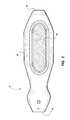
- FIG. 2is a top view of a wireless probe that can be employed in connection with the low power ultrasound system shown in FIG. 1A ;
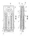
- FIG. 3is a simplified block diagram of internal components of the ultrasound probe shown in FIG. 2 ;
- FIG. 4Ais a top simplified view of one possible implementation of the components of the ultrasound probe shown in FIG. 3 according to one embodiment
- FIG. 4Bis a simplified side view of the components of the ultrasound probe shown in FIG. 4A ;
- FIG. 5Ais a simplified view of a transducer array in a head portion of the ultrasound probe shown in FIGS. 1A and 1B , showing one stage of operation of the transducer array according to one example embodiment;
- FIG. 5Bis a simplified view of the transducer array of FIG. 5A , showing a subsequent stage of operation of the transducer array;
- FIG. 6Ais a simplified view of the transducer array of FIG. 5A , showing one stage of operation of the transducer array according to another example embodiment.
- FIG. 6Bis a simplified view of the transducer array of FIG. 5A , showing a subsequent stage of operation of the transducer array.
- FIGS. 1-6Bdepict various features of embodiments of the present invention, which embodiments are generally directed to a system for performing ultrasound imaging on the body of a patient or other subject.
- the system to be describedrequires relatively low power levels in order to function, thereby enabling the system to take advantage of wireless technologies to un-tether the ultrasound probe from the base unit of the system. This, in turn, provides more flexibility for a clinician or other user of the system and simplifies the ultrasonic procedure.
- FIG. 1Ashows a low power ultrasound system, generally designated at 10 , configured in accordance with one example embodiment of the present invention.
- the low power ultrasound system (“system”) 10generally includes a base unit 12 and probe 14 .
- the base unit 12as pictured here includes a processor 16 for performing image processing functions on sonographic data retrieved by the probe 14 during an ultrasonic procedure.
- FIG. 1Ashows the probe 14 placed adjacent a surface 22 of a body 20 of a patient or other subject. Though understood to be used in applications such as that shown here in FIG. 1A , it is also appreciated that embodiments of the present invention may be modified for use with probes having other shapes and configurations, including probes configured for penetration into an orifice of the patient, for instance.
- the base unit 12further includes a display 18 .
- Image data processed by the processor 16 of the base unit 12are represented as an image on the display 18 .
- the imageis continually refreshed during operation of the system 10 .
- the base unit 12can be one of any number devices, including a dedicated ultrasound device, a desktop or laptop computer, etc.
- the system 10implements wireless technology, wherein the base unit 12 and the probe 14 are in two-way, wireless communication with one another.
- the base unit 12includes a base antenna 24 that wireless communicates with a probe antenna 26 included with the probe 14 .
- Wireless signals 28representing electromagnetic communication such as RF signals between the base unit 12 and the probe 14 , are also shown.
- sonographic data detected by the probe 14can be wirelessly transmitted by the probe antenna 26 to the base unit 12 via the base antenna 24 for processing by the processor 16 .
- wireless data transfer protocolsincluding Wireless USB, IEEE 802.x, BLUETOOTH, WIMAX, etc., may be employed for such data transfer as described herein.
- FIG. 1Brepresents another possible embodiment, wherein the base unit 12 of the low power ultrasound system 10 is communicatively coupled with the probe 14 not wirelessly, but via a cable 30 .
- the low power ultrasound system as described hereinmay be employed with a wireless, non-wireless, or even hybrid wireless/cabled communication link between the base unit and the probe.
- the probe 14is a wireless probe and includes a probe housing that acts as a covering for various internal components of the probe.
- a head 42is included in the probe 14 and houses the array of crystals that act as transducers to enable insonation of an object within the body of the patient to be imaged during ultrasound procedures.
- a location 44is specified, depicting one possible location for inclusion of an internal probe antenna enabling wireless communication with the base unit 12 as generally depicted in FIG. 1A .
- a location 46is also designated for the inclusion of various buttons (not shown) that enable clinician control of the probe 14 and the base unit 12 during ultrasound procedures.
- the probe 14 as shown in FIG. 2can be desirably included within the sterile field of a patient undergoing an ultrasound procedure in preparation for receiving an intravenous catheter, such as a PICC line, for instance.
- an intravenous cathetersuch as a PICC line
- the particular design of the probe 14 as shown in FIG. 2together with the specified location for the various components thereof—both internal and external—can be varied such that the size, look, and configuration of the probe may be modified from what is explicitly shown here.
- FIG. 3in describing various internal components included in the probe 14 of the system 10 , according to one embodiment.
- the layout and configuration of the components in FIG. 3shown in simplified form, enable the system 10 to operate in a low power configuration.
- the low power requirements of the components of the probe 14 shown in FIG. 3enable various advantages to be realized, including the ability for the probe to operate wirelessly with respect to the base unit 12 while still having a suitable operating time between recharging.
- the components to be described in connection with FIG. 3can be configured as a single device or multiple devices, as may be appreciated by one skilled in the art.
- FIG. 3shows that the probe 14 internally includes a crystal array 50 , each crystal of the array functioning as a piezoelectric transducer.
- the crystal array 50here includes 64 crystals and is located in the head 42 ( FIG. 2 ) of the Probe 14 and is linearly arranged in the present embodiment. In other embodiments, both the number and arrangement of the crystals can vary.
- One or more pulser/receiver modules 52are operably connected to the crystal array 50 and are configured to drive one or more active crystals in the crystal array 50 during operation of the system 10 so as to cause the respective crystal to produce a transmit pulse of ultrasonic waves, well known in the art.
- the pulser/receiver modules 52are also configured to receive electrical pulses representing received echo pulses detected by the active crystals of the crystal array 50 , wherein the echo pulses are produced as a result of reflection of the transmit pulses by an object to be imaged within the patient body, such as a vein or artery.
- a signal line 66is shown interposed between various of the components depicted in FIG. 3 , including the crystal array 50 , the pulser/receiver modules 52 , etc. Note that the signal line 66 is representative of one or more signal paths on which signals associated with ultrasonic echo receive pulses are carried between the internal probe components described herein. As such, the signal line 66 may take one or more of several forms between the various internal probe components, as known by one skilled in the art.
- An analog multiplexer 54is operably connected to the pulser/receiver modules 52 and is configured to multiplex multiple electrical pulses representing the received echo pulses forwarded by the pulser/receiver modules.
- the multiplexer 54 in the present embodimentis a composite configuration of eight “1-of-8” multiplexers, each of which is operably connected to a corresponding plurality of eight pulser/receiver modules 52 (see FIGS. 4A , 4 B).
- the composite multiplexer 54is operably connected to a field-programmable gate array (or “FPGA,” described below at 60 ) having 3 binary-decoded select lines and 8 enable lines to the eight multiplexers to enable the signals from one multiplexer at a time to be forwarded along the signal line 66 .
- FPGAfield-programmable gate array
- a single low-noise amplifier (“LNA”) 56is operably connected to the multiplexer 54 and is configured to amplify the multiplexed signal received from the multiplexer. Note that the LNA 56 receives a single-ended analog signal from the multiplexer 54 and, in addition to amplifying it, produces for output a differential analog signal. This differential analog signal is forwarded to a single analog-to-digital converter (“ADC”) 58 , which converts it to a digital signal.
- the ADC 58is a 16-bit ADC in one embodiment, such as part number LTC2203CUK or LTC2203IUK, sold by Linear Technology, 1630 McCarthy Boulevard., Milpitas, Calif., 95035-7417.
- the components of the present probe 14are configured such that only a single signal is amplified by a single amplifier, i.e., the LNA 56 , and converted by a single ADC, i.e., the ADC 58 , then forwarded for more processing. In this way, the probe 14 has a reduced size, reduced complexity, and lower power consumption when compared to other, known ultrasound systems.
- the digital signal produced by the ADC 58is then forwarded by the ADC 58 to a field programmable gate array (“FPGA”) 60 and a central processing unit (“CPU”) 62 before the signal is transmitted to the base unit 12 via a wireless node 64 .
- FPGAfield programmable gate array
- CPUcentral processing unit
- the CPU 62is NXP part number LPC2888FET180-S, sold by Royal Philips Electronics, and is employed to govern the FPGA 60 and communication interfaces, such as a wireless node 64 to be described below.
- the wireless node 64could include both Wireless USB and BLUETOOTH wireless data transfer protocols for the wireless transfer of signals from the probe 14 to the base unit 12 .
- the wireless nodescan be omitted in one embodiment in favor of a cabled interface between the base unit and the probe. Indeed, in one embodiment, the base unit and probe can be connected via a USB cable. In such a case, the power requirements of the internal components of the probe could be met by the power supply provided by one or more USB outlets of the base unit, if desired, or by a combination of battery and USB-provided power.
- the base unit 12 in the embodiment shown in FIG. 1Ais configured for wireless communication with the wireless probe 14 .
- the base unit 12wirelessly receives the digital signal that is produced and forwarded via the wireless node 64 as described immediately above.
- the processor 16then processes the digital signal according to standard image processing procedures and produces an image that is sent to the display 18 for viewing.
- FIG. 3shows that the probe 14 includes other internal components related to its operation.
- a plurality of pulser buffers 68are included and operably connected to the pulser/receiver modules 52 via one or more communication lines 70 .
- the pulser buffers 68are governed by the FPGA 60 via a communication line 72 , which includes in one embodiment 64 signal lines and one enable/disable line, according to the inclusion of 64 transducers in the crystal array 50 . So configured, the FPGA 60 assists in activating the proper number of pulser/receiver modules 52 during operation of the device 10 .
- communication lines 72extend from the FPGA 60 to the ADC 58 and the multiplexer 54 to enable the FPGA 60 to govern their operation as well.
- a power supply 80is included in the probe 14 to power the components already described above in connection with FIG. 3 .
- the power supply 80is a rechargeable lithium-ion-type battery, though other battery types or alternative power supplies may also be used.
- a supply status lineextends between the power supply 80 and the CPU 62 so as to enable the CPU to monitor battery voltage and to enable the CPU to detect any power supply malfunctions.
- one or more smart batteriesmay alternatively be used.
- FIG. 3list voltage values at their corresponding nodes. Note that these voltage values can vary according to the particular configuration of the device(s). It is therefore appreciated that these voltage values are exemplary only, and should not be construed as limiting the present invention in any way.
- FIGS. 4A and 4Bdepict one possible configuration for arrangement of the various internal components of the probe 14 .
- these figuresshow the linear crystal array 50 connected to a top printed circuit board (“PCB”) 90 via a flex circuit 92 .
- the plurality of pulser/receiver modules 52are arranged on top and bottom surfaces of the top PCB 90 A and a bottom PCB 90 C as well, totaling 64 pulser/receiver modules in the present embodiment, though this number can change according to the particular application.
- Two pulser buffers 68are arranged on the top and bottom surfaces of the top PCB 90 A and the bottom PCB 90 C.
- two multiplexers 54are arranged on the top and bottom surfaces of the top PCB 90 A and the bottom PCB 90 C.
- Connectors 94 Aare included to interconnect the top and bottom PCBs 90 A and 90 C to each other and to the flex circuit 92 .
- Connectors 94 Bare included to interconnect the top and bottom PCBs 90 A and 90 C with a middle PCB 90 B.
- the middle PCB 90 Bincludes LNA 56 , the FPGA 60 , and the CPU 62 , together with other probe components, which have been removed for the sake of clarity.
- the three PCBs 90 A- 90 Care arranged in a stacked “clamshell” design, best seen in FIG. 4B , thereby providing an efficient use of space so as to minimize the size of the probe 14 .
- the size of the probe 14is approximately 1.5 inches wide, 3.5 inches long, and 0.5 inch high.
- FIGS. 5A-6Bdepict various operational aspects of the probe 14 during operation of the system 10 to ultrasonically image an object 102 , such as a vein, artery, or other feature in the body of a patient.
- a portion 100is shown of the crystal array 50 ( FIGS. 4A , 4 B), including individually numbered crystal transducers 1 - 34 .
- the crystal array of which the portion 100 is a partincludes 64 crystal transducers linearly arranged in the manner shown in FIG. 5A , though both the number and arrangement of the crystal transducers can vary from what is shown here.
- FIGS. 5A-6Bdepict one such technique.
- FIGS. 6A and 6Bdescribe another technique. It is appreciated that either of these techniques, or some other technique that is different than, or an amalgam of, the techniques described herein, may be used to produce ultrasonic images using the system 10 .
- a plurality of ultrasonic transmit pulses 104are emitted from 32 contiguous transducers, for example, of the crystal array portion 100 toward the object 102 to be imaged.
- the number of transducers used in any imaging proceduremay be more or less than 32 can vary according to many factors, including the size and position of the object to be imaged, etc.
- Transducer 1 of the array aloneis then activated so as to be able to receive and detect an ultrasonic echo receive pulse 106 produced by partial reflection by the object 102 of one or more of the transmit pulses 104 .
- the receive pulse 106is transmitted through the system in the manner described in connection with FIG. 3 .
- FIG. 5Bshows a subsequent stage of the technique, where a new round of ultrasonic transmit pulses 104 are sent a point in time after, e.g., in rapid succession to, the transmit pulses shown in FIG. 5A . Then, transducer 2 of the array alone is then activated so as to be able to receive and detect a subsequent ultrasonic echo receive pulse 106 produced by partial reflection by the object 102 of one or more of the transmit pulses 104 . This subsequent receive pulse 106 is transmitted through the system in the manner described in connection with FIG. 3 .
- the above processis repeated while advancing the lone active receiving transducer by one through the series of transmitting transducers in order to shape and focus the resulting image of the insonated object 102 .
- thissignifies cycling the receiving transducer function through all of the transmitting transducers, though this number can be varied if desired or needed for a particular application.
- the number of active transducers used to send transmit pulses, the number of transducers receiving an echo pulse at one time, the pattern of activation of the receiving transducers, etc.can be varied.
- FIGS. 6A and 6Bshow another possible ultrasonic scanning technique.
- a single crystal transducere.g., crystal 1 alone in the illustrated example, is activated to emit an ultrasonic transmit pulse toward the object 102 to be imaged.
- Crystal 1is kept active to receive the echo receive pulse 106 reflected by the object 102 .
- the detected signalis forwarded through the probe 14 to the base unit 12 as has been described in connection with FIG. 3 .
Landscapes
- Engineering & Computer Science (AREA)
- Health & Medical Sciences (AREA)
- Physics & Mathematics (AREA)
- Life Sciences & Earth Sciences (AREA)
- Remote Sensing (AREA)
- Radar, Positioning & Navigation (AREA)
- Computer Networks & Wireless Communication (AREA)
- General Physics & Mathematics (AREA)
- Molecular Biology (AREA)
- Veterinary Medicine (AREA)
- Heart & Thoracic Surgery (AREA)
- Medical Informatics (AREA)
- Radiology & Medical Imaging (AREA)
- Surgery (AREA)
- Animal Behavior & Ethology (AREA)
- General Health & Medical Sciences (AREA)
- Public Health (AREA)
- Biomedical Technology (AREA)
- Biophysics (AREA)
- Nuclear Medicine, Radiotherapy & Molecular Imaging (AREA)
- Pathology (AREA)
- Acoustics & Sound (AREA)
- Gynecology & Obstetrics (AREA)
- Computer Hardware Design (AREA)
- General Engineering & Computer Science (AREA)
- Computer Vision & Pattern Recognition (AREA)
- Ultra Sonic Daignosis Equipment (AREA)
Abstract
Description
Claims (17)
Priority Applications (2)
| Application Number | Priority Date | Filing Date | Title |
|---|---|---|---|
| US12/100,983US8500645B2 (en) | 2007-04-10 | 2008-04-10 | Low power ultrasound system |
| US13/959,599US9826960B2 (en) | 2007-04-10 | 2013-08-05 | Low power ultrasound system |
Applications Claiming Priority (2)
| Application Number | Priority Date | Filing Date | Title |
|---|---|---|---|
| US92269507P | 2007-04-10 | 2007-04-10 | |
| US12/100,983US8500645B2 (en) | 2007-04-10 | 2008-04-10 | Low power ultrasound system |
Related Child Applications (1)
| Application Number | Title | Priority Date | Filing Date |
|---|---|---|---|
| US13/959,599DivisionUS9826960B2 (en) | 2007-04-10 | 2013-08-05 | Low power ultrasound system |
Publications (2)
| Publication Number | Publication Date |
|---|---|
| US20080255451A1 US20080255451A1 (en) | 2008-10-16 |
| US8500645B2true US8500645B2 (en) | 2013-08-06 |
Family
ID=39535526
Family Applications (2)
| Application Number | Title | Priority Date | Filing Date |
|---|---|---|---|
| US12/100,983Active2031-09-15US8500645B2 (en) | 2007-04-10 | 2008-04-10 | Low power ultrasound system |
| US13/959,599Active2029-02-22US9826960B2 (en) | 2007-04-10 | 2013-08-05 | Low power ultrasound system |
Family Applications After (1)
| Application Number | Title | Priority Date | Filing Date |
|---|---|---|---|
| US13/959,599Active2029-02-22US9826960B2 (en) | 2007-04-10 | 2013-08-05 | Low power ultrasound system |
Country Status (7)
| Country | Link |
|---|---|
| US (2) | US8500645B2 (en) |
| EP (2) | EP2135110B1 (en) |
| JP (1) | JP5452468B2 (en) |
| KR (2) | KR20100016338A (en) |
| CN (1) | CN101680948B (en) |
| ES (1) | ES2397553T3 (en) |
| WO (1) | WO2008124841A2 (en) |
Cited By (8)
| Publication number | Priority date | Publication date | Assignee | Title |
|---|---|---|---|---|
| US20150099977A1 (en)* | 2013-10-08 | 2015-04-09 | Samsung Electronics Co., Ltd. | Apparatus and method for beamforming |
| US20160374645A1 (en)* | 2013-12-05 | 2016-12-29 | Dongguk University Industry-Academic | Method for performing low power mode in portable ultrasonic diagnostic apparatus and portable ultrasonic diagnostic apparatus for applying same |
| US9826960B2 (en) | 2007-04-10 | 2017-11-28 | C. R. Bard, Inc. | Low power ultrasound system |
| US10469846B2 (en) | 2017-03-27 | 2019-11-05 | Vave Health, Inc. | Dynamic range compression of ultrasound images |
| US10856843B2 (en) | 2017-03-23 | 2020-12-08 | Vave Health, Inc. | Flag table based beamforming in a handheld ultrasound device |
| US11446003B2 (en) | 2017-03-27 | 2022-09-20 | Vave Health, Inc. | High performance handheld ultrasound |
| US11504097B2 (en) | 2017-09-01 | 2022-11-22 | Clarius Mobile Health Corp. | Systems and methods for acquiring raw ultrasound data from an ultrasound machine using a wirelessly connected device |
| US11531096B2 (en) | 2017-03-23 | 2022-12-20 | Vave Health, Inc. | High performance handheld ultrasound |
Families Citing this family (28)
| Publication number | Priority date | Publication date | Assignee | Title |
|---|---|---|---|---|
| US7984651B2 (en)* | 2006-11-10 | 2011-07-26 | Penrith Corporation | Transducer array imaging system |
| US8600299B2 (en)* | 2006-11-10 | 2013-12-03 | Siemens Medical Solutions Usa, Inc. | Transducer array imaging system |
| EP2164397B1 (en)* | 2007-06-01 | 2019-03-27 | Koninklijke Philips N.V. | Wireless ultrasound probe user interface |
| JP5199139B2 (en)* | 2009-01-28 | 2013-05-15 | 富士フイルム株式会社 | Ultrasonic probe and ultrasonic diagnostic apparatus |
| US8345508B2 (en)* | 2009-09-20 | 2013-01-01 | General Electric Company | Large area modular sensor array assembly and method for making the same |
| KR101142390B1 (en)* | 2010-02-04 | 2012-05-18 | 주식회사 마린디지텍 | Energy providing apparatus using multi probe |
| CN102018532A (en)* | 2010-11-25 | 2011-04-20 | 北京悦琦创通科技有限公司 | Continuous wave probe structure for ultrasonic Doppler |
| US8608738B2 (en) | 2010-12-06 | 2013-12-17 | Soulor Surgical, Inc. | Apparatus for treating a portion of a reproductive system and related methods of use |
| US10470788B2 (en)* | 2010-12-07 | 2019-11-12 | Misonix, Inc | Ultrasonic instrument, associated method of use and related manufacturing method |
| US9649091B2 (en) | 2011-01-07 | 2017-05-16 | General Electric Company | Wireless ultrasound imaging system and method for wireless communication in an ultrasound imaging system |
| US20120245466A1 (en)* | 2011-03-25 | 2012-09-27 | Infosys Technologies, Ltd. | Method and system for capturing medical imaging data |
| JP2012217618A (en)* | 2011-04-08 | 2012-11-12 | Fujifilm Corp | Ultrasound diagnostic apparatus |
| US10499878B2 (en)* | 2012-07-26 | 2019-12-10 | Interson Corporation | Portable ultrasonic imaging probe including a transducer array |
| US20150238168A1 (en)* | 2012-09-13 | 2015-08-27 | Koninklijke Philips N.V. | Mobile 3d wireless ultrasound image acquisition device and ultrasound imaging system |
| CN105007826B (en)* | 2013-03-07 | 2018-03-27 | 皇家飞利浦有限公司 | Multipurpose ultrasonic image capture device |
| US20140358005A1 (en)* | 2013-05-31 | 2014-12-04 | eagleyemed, Inc. | Speckle and noise reduction in ultrasound images |
| US9901324B2 (en) | 2013-09-03 | 2018-02-27 | Samsung Electronics Co., Ltd. | Ultrasound probe and method of operating the same |
| US9918736B2 (en)* | 2013-09-25 | 2018-03-20 | Covidien Lp | Ultrasonic dissector and sealer |
| CN103604492A (en)* | 2013-12-03 | 2014-02-26 | 上海现代先进超精密制造中心有限公司 | Ultrasonic frequency detection system and method of ultrasonic wave machining tool detection |
| WO2016057631A1 (en) | 2014-10-08 | 2016-04-14 | Butterfly Network, Inc. | Parameter loader for ultrasound probe and related apparatus and methods |
| US10816650B2 (en) | 2016-05-27 | 2020-10-27 | Interson Corporation | Ultrasonic imaging probe including composite aperture receiving array |
| US11039814B2 (en) | 2016-12-04 | 2021-06-22 | Exo Imaging, Inc. | Imaging devices having piezoelectric transducers |
| CN108742701B (en)* | 2018-03-27 | 2021-11-12 | 苏州佳世达电通有限公司 | Expansion module and expansion module for ultrasonic system |
| US11971477B2 (en) | 2018-09-25 | 2024-04-30 | Exo Imaging, Inc. | Imaging devices with selectively alterable characteristics |
| CA3124116A1 (en) | 2018-12-27 | 2020-07-02 | Exo Imaging, Inc. | Methods to maintain image quality in ultrasound imaging at reduced cost, size, and power |
| IL311310B2 (en) | 2020-03-05 | 2025-05-01 | Exo Imaging Inc | Ultrasonic imaging device with programmable anatomy and flow imaging |
| US11857291B2 (en)* | 2020-07-16 | 2024-01-02 | Photosound Technologies Inc. | Serial architecture and energy saving methods for ultrasound and thermoacoustic systems |
| US11504093B2 (en) | 2021-01-22 | 2022-11-22 | Exo Imaging, Inc. | Equalization for matrix based line imagers for ultrasound imaging systems |
Citations (130)
| Publication number | Priority date | Publication date | Assignee | Title |
|---|---|---|---|---|
| US3914748A (en) | 1974-04-29 | 1975-10-21 | Texas Instruments Inc | Isolation-element CCD serial-parallel-serial analog memory |
| US3918024A (en) | 1974-06-24 | 1975-11-04 | Albert Macovski | Ultrasonic array for reflection imaging |
| US4152678A (en) | 1976-07-01 | 1979-05-01 | Board of Trustees of the Leland Stanford Jr. Unv. | Cascade charge coupled delay line device for compound delays |
| US4159462A (en) | 1977-08-18 | 1979-06-26 | General Electric Company | Ultrasonic multi-sector scanner |
| US4334432A (en) | 1979-02-20 | 1982-06-15 | The Commonwealth Of Australia - Dept. Of Health | Ultrasonic linear array beamforming method and apparatus |
| US4413629A (en) | 1982-04-22 | 1983-11-08 | Cryomedics, Inc. | Portable ultrasonic Doppler System |
| US4542653A (en) | 1983-11-21 | 1985-09-24 | Advanced Technology Laboratories, Inc. | Apparatus and method for beamforming in an ultrasonic transducer array |
| JPH02156933A (en) | 1988-12-08 | 1990-06-15 | Toshiba Corp | Ultrasonic drive device |
| US5005419A (en) | 1988-06-16 | 1991-04-09 | General Electric Company | Method and apparatus for coherent imaging system |
| US5108759A (en) | 1987-04-01 | 1992-04-28 | Ranney David F | Endothelial envelopment drug carriers |
| WO1992017118A1 (en) | 1991-04-04 | 1992-10-15 | Shturman Cardiology Systems, Inc. | Method and apparatus for in vivo heart valve decalcification |
| US5259386A (en) | 1992-06-19 | 1993-11-09 | Advanced Cardiovascular Systems, Inc. | Flow monitor and vascular access system with continuously variable frequency control |
| US5263483A (en) | 1991-11-20 | 1993-11-23 | Matsushita Electric Industrial Co., Ltd. | Beam former for ultrasonic diagnostic apparatus |
| US5265613A (en) | 1992-04-03 | 1993-11-30 | Telmed, Inc. | Portable non-invasive testing apparatus with logarithmic amplification |
| US5268877A (en) | 1992-05-11 | 1993-12-07 | The United States Of America As Represented By The Secretary Of The Navy | Digital beamforming and filtering circuit |
| US5295485A (en) | 1991-12-13 | 1994-03-22 | Hitachi, Ltd. | Ultrasonic diagnostic system |
| US5345426A (en) | 1993-05-12 | 1994-09-06 | Hewlett-Packard Company | Delay interpolator for digital phased array ultrasound beamformers |
| US5369624A (en) | 1993-03-26 | 1994-11-29 | Siemens Medical Systems, Inc. | Digital beamformer having multi-phase parallel processing |
| WO1995004502A1 (en) | 1993-08-05 | 1995-02-16 | Cardiovascular Dynamics, Inc. | Coaxial cable vascular access system |
| WO1995012354A1 (en) | 1993-11-04 | 1995-05-11 | Niagara Technology Incorporated | High resolution ultrasonic imaging apparatus and method |
| US5522391A (en) | 1994-08-09 | 1996-06-04 | Hewlett-Packard Company | Delay generator for phased array ultrasound beamformer |
| US5544128A (en) | 1994-07-05 | 1996-08-06 | Siemens Medical Systems, Inc. | Multi-beam digital beamforming method and apparatus |
| US5590658A (en) | 1995-06-29 | 1997-01-07 | Teratech Corporation | Portable ultrasound imaging system |
| US5622177A (en)* | 1993-07-08 | 1997-04-22 | Siemens Aktiengesellschaft | Ultrasound imaging system having a reduced number of lines between the base unit and the probe |
| US5640960A (en) | 1995-04-18 | 1997-06-24 | Imex Medical Systems, Inc. | Hand-held, battery operated, doppler ultrasound medical diagnostic device with cordless probe |
| US5685307A (en) | 1995-02-28 | 1997-11-11 | Iowa State University Research Foundation, Inc. | Method and apparatus for tissue characterization of animals using ultrasound |
| US5722412A (en) | 1996-06-28 | 1998-03-03 | Advanced Technology Laboratories, Inc. | Hand held ultrasonic diagnostic instrument |
| WO1998028631A2 (en) | 1996-12-24 | 1998-07-02 | Teratech Corporation | Ultrasound scan conversion with spatial dithering |
| US5782769A (en) | 1996-06-28 | 1998-07-21 | Advanced Technology Laboratories, Inc. | Ultrasonic diagnostic image flash suppression technique |
| US5817024A (en) | 1996-06-28 | 1998-10-06 | Sonosight, Inc. | Hand held ultrasonic diagnostic instrument with digital beamformer |
| JPH10290799A (en) | 1997-04-21 | 1998-11-04 | Olympus Optical Co Ltd | Ultrasonograph |
| US5865733A (en) | 1997-02-28 | 1999-02-02 | Spacelabs Medical, Inc. | Wireless optical patient monitoring apparatus |
| US5893363A (en) | 1996-06-28 | 1999-04-13 | Sonosight, Inc. | Ultrasonic array transducer transceiver for a hand held ultrasonic diagnostic instrument |
| US5964709A (en) | 1995-06-29 | 1999-10-12 | Teratech Corporation | Portable ultrasound imaging system |
| US5997479A (en) | 1998-05-28 | 1999-12-07 | Hewlett-Packard Company | Phased array acoustic systems with intra-group processors |
| US6102863A (en) | 1998-11-20 | 2000-08-15 | Atl Ultrasound | Ultrasonic diagnostic imaging system with thin cable ultrasonic probes |
| US6117085A (en) | 1998-11-20 | 2000-09-12 | Atl Ultrasound, Inc. | Ultrasonic diagnostic imaging system with cordless scanhead charger |
| US6126608A (en) | 1999-05-18 | 2000-10-03 | Pie Medical Equipment B.V. | Portable ultrasound diagnostic system with handsfree display |
| US6135958A (en) | 1998-08-06 | 2000-10-24 | Acuson Corporation | Ultrasound imaging system with touch-pad pointing device |
| US6135961A (en) | 1996-06-28 | 2000-10-24 | Sonosite, Inc. | Ultrasonic signal processor for a hand held ultrasonic diagnostic instrument |
| US6139496A (en) | 1999-04-30 | 2000-10-31 | Agilent Technologies, Inc. | Ultrasonic imaging system having isonification and display functions integrated in an easy-to-manipulate probe assembly |
| US6142946A (en) | 1998-11-20 | 2000-11-07 | Atl Ultrasound, Inc. | Ultrasonic diagnostic imaging system with cordless scanheads |
| US6203498B1 (en) | 1996-06-28 | 2001-03-20 | Sonosite, Inc. | Ultrasonic imaging device with integral display |
| US6213951B1 (en) | 1999-02-19 | 2001-04-10 | Acuson Corporation | Medical diagnostic ultrasound method and system for contrast specific frequency imaging |
| US6248073B1 (en)* | 1995-06-29 | 2001-06-19 | Teratech Corporation | Ultrasound scan conversion with spatial dithering |
| US6251073B1 (en)* | 1999-08-20 | 2001-06-26 | Novasonics, Inc. | Miniaturized ultrasound apparatus and method |
| WO2001052753A1 (en) | 2000-01-18 | 2001-07-26 | University Of Lausanne | High performance cannulas |
| US6344024B1 (en) | 1997-05-12 | 2002-02-05 | Dwl Elektronische Systeme Gmbh | Multifrequency ultrasound probe |
| US20020016545A1 (en) | 2000-04-13 | 2002-02-07 | Quistgaard Jens U. | Mobile ultrasound diagnostic instrument and system using wireless video transmission |
| US6375617B1 (en) | 2000-08-24 | 2002-04-23 | Atl Ultrasound | Ultrasonic diagnostic imaging system with dynamic microbeamforming |
| US6379305B1 (en) | 2000-04-05 | 2002-04-30 | Janet Stoner Eugley | Early-fetal-heartbeat-detection device and method |
| US6383139B1 (en) | 1996-06-28 | 2002-05-07 | Sonosite, Inc. | Ultrasonic signal processor for power doppler imaging in a hand held ultrasonic diagnostic instrument |
| US20020065464A1 (en) | 2000-11-30 | 2002-05-30 | Murphy Kieran P | Imaging device |
| US6416475B1 (en) | 1996-06-28 | 2002-07-09 | Sonosite, Inc. | Ultrasonic signal processor for a hand held ultrasonic diagnostic instrument |
| CN1361871A (en) | 1999-06-22 | 2002-07-31 | 垓技术公司 | Ultrasound probe with integrated electronics |
| US6440072B1 (en) | 2000-03-30 | 2002-08-27 | Acuson Corporation | Medical diagnostic ultrasound imaging system and method for transferring ultrasound examination data to a portable computing device |
| US6471651B1 (en)* | 1999-05-05 | 2002-10-29 | Sonosite, Inc. | Low power portable ultrasonic diagnostic instrument |
| US6475146B1 (en) | 2001-09-24 | 2002-11-05 | Siemens Medical Solutions Usa, Inc. | Method and system for using personal digital assistants with diagnostic medical ultrasound systems |
| US6478740B2 (en) | 2000-09-26 | 2002-11-12 | Sean Souney | Portable hand-carry satellite diagnostic ultrasound system for general and cardiac imaging |
| US6482158B2 (en) | 2000-05-19 | 2002-11-19 | Healthetech, Inc. | System and method of ultrasonic mammography |
| US20030013966A1 (en) | 1996-06-28 | 2003-01-16 | Sonosite, Inc. | Balance body ultrasound system |
| US6540682B1 (en) | 2000-11-09 | 2003-04-01 | Koninklijke Philips Electronics N.V. | Portable, configurable and scalable ultrasound imaging system |
| US6540685B1 (en) | 2000-11-09 | 2003-04-01 | Koninklijke Philips Electronics N.V. | Ultrasound diagnostic device |
| US20030097071A1 (en) | 2001-11-21 | 2003-05-22 | Menachem Halmann | Method and system for PDA-based ultrasound system |
| US6569101B2 (en) | 2001-04-19 | 2003-05-27 | Sonosite, Inc. | Medical diagnostic ultrasound instrument with ECG module, authorization mechanism and methods of use |
| US6575908B2 (en) | 1996-06-28 | 2003-06-10 | Sonosite, Inc. | Balance body ultrasound system |
| US20030139664A1 (en) | 2002-01-17 | 2003-07-24 | Siemens Medical Solutions Usa, Inc. | Segmented handheld medical ultrasound system and method |
| US6605043B1 (en) | 1998-11-19 | 2003-08-12 | Acuson Corp. | Diagnostic medical ultrasound systems and transducers utilizing micro-mechanical components |
| WO2003072000A1 (en) | 2002-02-22 | 2003-09-04 | Omnisonics Medical Technologies, Inc. | Apparatus and method for using a vascular introducer with an ultrasonic probe |
| US6645148B2 (en) | 2001-03-20 | 2003-11-11 | Vermon | Ultrasonic probe including pointing devices for remotely controlling functions of an associated imaging system |
| US20030236539A1 (en) | 1999-10-05 | 2003-12-25 | Omnisonics Medical Technologies, Inc. | Apparatus and method for using an ultrasonic probe to clear a vascular access device |
| US20040002652A1 (en)* | 2002-06-27 | 2004-01-01 | Siemens Medical Solutions Usa, Inc. | Receive circuit for ultrasound imaging |
| US20040002656A1 (en)* | 2002-06-27 | 2004-01-01 | Siemens Medical Solutions Usa, Inc. | Multi-dimensional transducer arrays and method of manufacture |
| US20040015079A1 (en)* | 1999-06-22 | 2004-01-22 | Teratech Corporation | Ultrasound probe with integrated electronics |
| WO2004032791A2 (en) | 2002-09-20 | 2004-04-22 | Flowmedica, Inc. | Method and apparatus for selective material delivery via an intra-renal catheter |
| US6746402B2 (en) | 2002-01-02 | 2004-06-08 | E. Tuncay Ustuner | Ultrasound system and method |
| US20040158154A1 (en) | 2003-02-06 | 2004-08-12 | Siemens Medical Solutions Usa, Inc. | Portable three dimensional diagnostic ultrasound imaging methods and systems |
| US20040181206A1 (en) | 2003-03-12 | 2004-09-16 | Chiu Jessica G. | Retrograde pressure regulated infusion |
| US6806623B2 (en)* | 2002-06-27 | 2004-10-19 | Siemens Medical Solutions Usa, Inc. | Transmit and receive isolation for ultrasound scanning and methods of use |
| US20040225220A1 (en) | 2003-05-06 | 2004-11-11 | Rich Collin A. | Ultrasound system including a handheld probe |
| WO2004096062A1 (en) | 2003-03-25 | 2004-11-11 | Omnisonics Medical Technologies, Inc. | Apparatus and method for using an ultrasonic probe to clear a vascular access device |
| WO2004107965A2 (en) | 2002-09-20 | 2004-12-16 | Flowmedica, Inc. | Systems and methods for performing bi-lateral interventions or diagnosis in branched body lumens |
| US20050057304A1 (en) | 2003-09-15 | 2005-03-17 | Barrie Gilbert | Single-ended input, differential output low noise amplifier |
| US20050068221A1 (en) | 2003-09-30 | 2005-03-31 | Freeman Steven R. | Ultrasonic signal acquisition in the digital beamformer |
| WO2005043188A1 (en) | 2003-11-03 | 2005-05-12 | Koninklijke Philips Electronics, N.V. | Ultrasonic multiple beam transmission using single crystal transducer |
| JP2005168903A (en) | 2003-12-12 | 2005-06-30 | Matsushita Electric Ind Co Ltd | Ultrasonic diagnostic equipment |
| US20050148878A1 (en)* | 2003-12-19 | 2005-07-07 | Siemens Medical Solutions Usa, Inc.. | Probe based digitizing or compression system and method for medical ultrasound |
| US20050148873A1 (en)* | 2003-12-19 | 2005-07-07 | Siemens Medical Solutions Usa, Inc. | Ultrasound adaptor methods and systems for transducer and system separation |
| US20050181343A1 (en) | 2004-02-02 | 2005-08-18 | Ault Mark J. | Ultrasound guided vascular access training device |
| US6936008B2 (en) | 1999-08-20 | 2005-08-30 | Zonare Medical Systems, Inc. | Ultrasound system with cableless coupling assembly |
| US20050203392A1 (en)* | 2004-02-26 | 2005-09-15 | Siemens Medical Solutions Usa, Inc. | Receive circuit for minimizing channels in ultrasound imaging |
| US20050228281A1 (en) | 2004-03-31 | 2005-10-13 | Nefos Thomas P | Handheld diagnostic ultrasound system with head mounted display |
| WO2005099345A2 (en) | 2004-03-01 | 2005-10-27 | Sunnybrook And Women's College Health Sciences Centre | System and method for ecg-triggered retrospective color flow ultrasound imaging |
| US6962566B2 (en) | 2001-04-19 | 2005-11-08 | Sonosite, Inc. | Medical diagnostic ultrasound instrument with ECG module, authorization mechanism and methods of use |
| WO2006019848A1 (en) | 2004-07-21 | 2006-02-23 | Boston Scientific Scimed, Inc. | Ultrasound-activated anti-infective coatings and devices made thereof |
| WO2006026687A2 (en) | 2004-08-31 | 2006-03-09 | Graftcath, Inc. | Improved device and method for vascular access |
| US20060064159A1 (en) | 2003-10-08 | 2006-03-23 | Porter Christopher H | Device and method for vascular access |
| WO2006076326A2 (en) | 2005-01-10 | 2006-07-20 | Duke Fiduciary, Llc | Vascular implants and methods of fabricating the same |
| US20060184029A1 (en) | 2005-01-13 | 2006-08-17 | Ronen Haim | Ultrasound guiding system and method for vascular access and operation mode |
| US20060224110A1 (en) | 2005-03-17 | 2006-10-05 | Scott Michael J | Methods for minimally invasive vascular access |
| WO2006105009A1 (en) | 2005-03-25 | 2006-10-05 | Ample Medical, Inc. | Devices, systems, and methods for reshaping a heart valve annulus |
| WO2006116558A2 (en) | 1999-04-09 | 2006-11-02 | Evalve, Inc. | Device and methods for endoscopic annuloplasty |
| US20070016068A1 (en) | 2005-05-06 | 2007-01-18 | Sorin Grunwald | Ultrasound methods of positioning guided vascular access devices in the venous system |
| WO2007022133A1 (en) | 2005-08-15 | 2007-02-22 | Boston Scientific Limited | Medical image analysis |
| US20070161904A1 (en)* | 2006-11-10 | 2007-07-12 | Penrith Corporation | Transducer array imaging system |
| US20070239019A1 (en)* | 2006-02-13 | 2007-10-11 | Richard William D | Portable ultrasonic imaging probe than connects directly to a host computer |
| US20080114250A1 (en)* | 2006-11-10 | 2008-05-15 | Penrith Corporation | Transducer array imaging system |
| US20080114245A1 (en)* | 2006-11-10 | 2008-05-15 | Randall Kevin S | Transducer array imaging system |
| US20080114253A1 (en)* | 2006-11-10 | 2008-05-15 | Penrith Corporation | Transducer array imaging system |
| US20080114249A1 (en)* | 2006-11-10 | 2008-05-15 | Penrith Corporation | Transducer array imaging system |
| US20080114247A1 (en)* | 2006-11-10 | 2008-05-15 | Penrith Corporation | Transducer array imaging system |
| US20080114248A1 (en)* | 2006-11-10 | 2008-05-15 | Penrith Corporation | Transducer array imaging system |
| US20080114241A1 (en)* | 2006-11-10 | 2008-05-15 | Penrith Corporation | Transducer array imaging system |
| US20080114246A1 (en)* | 2006-11-10 | 2008-05-15 | Penrith Corporation | Transducer array imaging system |
| US20080114239A1 (en)* | 2006-11-10 | 2008-05-15 | Penrith Corporation | Transducer array imaging system |
| US20080119731A1 (en) | 2006-11-20 | 2008-05-22 | North American Medical Corporation | Portable ultrasound with touch screen interface |
| US20080119730A1 (en) | 2006-11-20 | 2008-05-22 | Medison Co., Ltd. | Portable ultrasound device |
| US20080119737A1 (en)* | 2006-11-16 | 2008-05-22 | Penrith Corporation | Integrated nerve stimulator and ultrasound imaging device |
| US20080125655A1 (en) | 2006-11-23 | 2008-05-29 | Medison Co., Ltd. | Portable ultrasound system |
| US20080161686A1 (en) | 2006-10-31 | 2008-07-03 | Nahi Halmann | Methods and apparatus for controlling handheld medical devices |
| US20080188750A1 (en)* | 2007-02-05 | 2008-08-07 | Penrith Corporation | Automated movement detection with audio and visual information |
| US20080208061A1 (en) | 2007-02-23 | 2008-08-28 | General Electric Company | Methods and systems for spatial compounding in a handheld ultrasound device |
| US20080281206A1 (en) | 2005-11-07 | 2008-11-13 | Stewart Gavin Bartlett | Ultrasound Measurement System and Method |
| WO2008124841A3 (en) | 2007-04-10 | 2008-11-27 | Bard Inc C R | Low power ultrasound system |
| US20090018443A1 (en)* | 2007-07-12 | 2009-01-15 | Colby Brian V | System for generating multiple beams from a single receive event |
| US20090093719A1 (en) | 2007-10-03 | 2009-04-09 | Laurent Pelissier | Handheld ultrasound imaging systems |
| US7549961B1 (en) | 2003-07-31 | 2009-06-23 | Sonosite, Inc. | System and method supporting imaging and monitoring applications |
| US20090198132A1 (en) | 2007-08-10 | 2009-08-06 | Laurent Pelissier | Hand-held ultrasound imaging device having reconfigurable user interface |
| US20100286527A1 (en)* | 2009-05-08 | 2010-11-11 | Penrith Corporation | Ultrasound system with multi-head wireless probe |
| US7874991B2 (en)* | 2006-06-23 | 2011-01-25 | Teratech Corporation | Ultrasound 3D imaging system |
Family Cites Families (18)
| Publication number | Priority date | Publication date | Assignee | Title |
|---|---|---|---|---|
| US3898840A (en)* | 1974-01-30 | 1975-08-12 | Automation Ind Inc | Multi-frequency ultrasonic search unit |
| JPS57170230A (en) | 1981-04-13 | 1982-10-20 | Ito Kenichi | Ultrasonic diagnostic apparatus |
| JPS62227326A (en) | 1986-03-27 | 1987-10-06 | 株式会社 日立メデイコ | Ultrasonic diagnostic apparatus |
| JPH0323853A (en) | 1989-06-22 | 1991-01-31 | Terumo Corp | Ultrasonic diagnostic apparatus |
| JP3094742B2 (en)* | 1993-09-03 | 2000-10-03 | 松下電器産業株式会社 | Ultrasound diagnostic equipment |
| US5957846A (en)* | 1995-06-29 | 1999-09-28 | Teratech Corporation | Portable ultrasound imaging system |
| CA2225622A1 (en)* | 1995-06-29 | 1997-01-16 | Steven R. Broadstone | Portable ultrasound imaging system |
| CN1189217A (en)* | 1995-06-29 | 1998-07-29 | 垓技术公司 | Portable ultrasound imaging system |
| US7500952B1 (en)* | 1995-06-29 | 2009-03-10 | Teratech Corporation | Portable ultrasound imaging system |
| JPH1057374A (en)* | 1996-06-11 | 1998-03-03 | Olympus Optical Co Ltd | Ultrasonograph |
| CN1242079A (en)* | 1996-12-24 | 2000-01-19 | 垓技术公司 | Ultrasound scan conversion with spatial dithering |
| US6292433B1 (en) | 1997-02-03 | 2001-09-18 | Teratech Corporation | Multi-dimensional beamforming device |
| US6808674B1 (en) | 2001-04-02 | 2004-10-26 | Rubbermaid Incorporated | Enclosed area on a blow molded article and method of making the same |
| US6890301B2 (en)* | 2002-03-05 | 2005-05-10 | Koninklijke Philips Electronics Nv | Diagnostic ultrasonic imaging system having combined scanhead connections |
| US6866632B1 (en)* | 2002-09-18 | 2005-03-15 | Zonare Medical Systems, Inc. | Adaptive receive aperture for ultrasound image reconstruction |
| US20050251035A1 (en)* | 2003-11-26 | 2005-11-10 | William Wong | Modular portable ultrasound systems |
| JP2006020749A (en)* | 2004-07-07 | 2006-01-26 | Aloka Co Ltd | Ultrasonic diagnostic device |
| JP5367247B2 (en)* | 2007-09-28 | 2013-12-11 | 富士フイルム株式会社 | Ultrasonic imaging apparatus and ultrasonic imaging method |
- 2008
- 2008-04-10ESES08745537Tpatent/ES2397553T3/enactiveActive
- 2008-04-10KRKR1020097023320Apatent/KR20100016338A/ennot_activeCeased
- 2008-04-10USUS12/100,983patent/US8500645B2/enactiveActive
- 2008-04-10EPEP08745537Apatent/EP2135110B1/enactiveActive
- 2008-04-10KRKR1020157008068Apatent/KR20150042870A/ennot_activeCeased
- 2008-04-10EPEP12154188.2Apatent/EP2450723B1/enactiveActive
- 2008-04-10WOPCT/US2008/059940patent/WO2008124841A2/enactiveApplication Filing
- 2008-04-10JPJP2010503208Apatent/JP5452468B2/enactiveActive
- 2008-04-10CNCN200880017662.2Apatent/CN101680948B/ennot_activeExpired - Fee Related
- 2013
- 2013-08-05USUS13/959,599patent/US9826960B2/enactiveActive
Patent Citations (169)
| Publication number | Priority date | Publication date | Assignee | Title |
|---|---|---|---|---|
| US3914748A (en) | 1974-04-29 | 1975-10-21 | Texas Instruments Inc | Isolation-element CCD serial-parallel-serial analog memory |
| US3918024A (en) | 1974-06-24 | 1975-11-04 | Albert Macovski | Ultrasonic array for reflection imaging |
| US4152678A (en) | 1976-07-01 | 1979-05-01 | Board of Trustees of the Leland Stanford Jr. Unv. | Cascade charge coupled delay line device for compound delays |
| US4159462A (en) | 1977-08-18 | 1979-06-26 | General Electric Company | Ultrasonic multi-sector scanner |
| US4334432A (en) | 1979-02-20 | 1982-06-15 | The Commonwealth Of Australia - Dept. Of Health | Ultrasonic linear array beamforming method and apparatus |
| US4413629A (en) | 1982-04-22 | 1983-11-08 | Cryomedics, Inc. | Portable ultrasonic Doppler System |
| US4542653A (en) | 1983-11-21 | 1985-09-24 | Advanced Technology Laboratories, Inc. | Apparatus and method for beamforming in an ultrasonic transducer array |
| US5108759A (en) | 1987-04-01 | 1992-04-28 | Ranney David F | Endothelial envelopment drug carriers |
| US5005419A (en) | 1988-06-16 | 1991-04-09 | General Electric Company | Method and apparatus for coherent imaging system |
| JPH02156933A (en) | 1988-12-08 | 1990-06-15 | Toshiba Corp | Ultrasonic drive device |
| US5295958A (en) | 1991-04-04 | 1994-03-22 | Shturman Cardiology Systems, Inc. | Method and apparatus for in vivo heart valve decalcification |
| WO1992017118A1 (en) | 1991-04-04 | 1992-10-15 | Shturman Cardiology Systems, Inc. | Method and apparatus for in vivo heart valve decalcification |
| US5443446A (en) | 1991-04-04 | 1995-08-22 | Shturman Cardiology Systems, Inc. | Method and apparatus for in vivo heart valve decalcification |
| US5263483A (en) | 1991-11-20 | 1993-11-23 | Matsushita Electric Industrial Co., Ltd. | Beam former for ultrasonic diagnostic apparatus |
| US5295485A (en) | 1991-12-13 | 1994-03-22 | Hitachi, Ltd. | Ultrasonic diagnostic system |
| US5265613A (en) | 1992-04-03 | 1993-11-30 | Telmed, Inc. | Portable non-invasive testing apparatus with logarithmic amplification |
| US5268877A (en) | 1992-05-11 | 1993-12-07 | The United States Of America As Represented By The Secretary Of The Navy | Digital beamforming and filtering circuit |
| EP0574923A2 (en) | 1992-06-19 | 1993-12-22 | Advanced Cardiovascular Systems, Inc. | Flow monitor and vascular access system with continuously variable frequency control |
| US5363852A (en) | 1992-06-19 | 1994-11-15 | Advanced Cardiovascular Systems, Inc. | Flow monitor and vascular access system with continuously variable frequency control |
| US5259386A (en) | 1992-06-19 | 1993-11-09 | Advanced Cardiovascular Systems, Inc. | Flow monitor and vascular access system with continuously variable frequency control |
| US5369624A (en) | 1993-03-26 | 1994-11-29 | Siemens Medical Systems, Inc. | Digital beamformer having multi-phase parallel processing |
| US5345426A (en) | 1993-05-12 | 1994-09-06 | Hewlett-Packard Company | Delay interpolator for digital phased array ultrasound beamformers |
| US5622177A (en)* | 1993-07-08 | 1997-04-22 | Siemens Aktiengesellschaft | Ultrasound imaging system having a reduced number of lines between the base unit and the probe |
| WO1995004502A1 (en) | 1993-08-05 | 1995-02-16 | Cardiovascular Dynamics, Inc. | Coaxial cable vascular access system |
| US5484416A (en) | 1993-08-05 | 1996-01-16 | Advanced Cardiovascular Systems, Inc. | Coaxial cable vascular access system for use in various needles |
| EP0712294A1 (en) | 1993-08-05 | 1996-05-22 | Cardiovascular Dynamics, Inc. | Coaxial cable vascular access system |
| WO1995012354A1 (en) | 1993-11-04 | 1995-05-11 | Niagara Technology Incorporated | High resolution ultrasonic imaging apparatus and method |
| CN1140982A (en) | 1993-11-04 | 1997-01-22 | 尼亚加拉技术股份有限公司 | High resolution ultrasonic imaging apparatus and method |
| US5544128A (en) | 1994-07-05 | 1996-08-06 | Siemens Medical Systems, Inc. | Multi-beam digital beamforming method and apparatus |
| US5522391A (en) | 1994-08-09 | 1996-06-04 | Hewlett-Packard Company | Delay generator for phased array ultrasound beamformer |
| US5685307A (en) | 1995-02-28 | 1997-11-11 | Iowa State University Research Foundation, Inc. | Method and apparatus for tissue characterization of animals using ultrasound |
| US5640960A (en) | 1995-04-18 | 1997-06-24 | Imex Medical Systems, Inc. | Hand-held, battery operated, doppler ultrasound medical diagnostic device with cordless probe |
| US5964709A (en) | 1995-06-29 | 1999-10-12 | Teratech Corporation | Portable ultrasound imaging system |
| US6379304B1 (en) | 1995-06-29 | 2002-04-30 | Teratech Corporation | Ultrasound scan conversion with spatial dithering |
| US5690114A (en) | 1995-06-29 | 1997-11-25 | Teratech Corporation | Portable ultrasound imaging system |
| US6248073B1 (en)* | 1995-06-29 | 2001-06-19 | Teratech Corporation | Ultrasound scan conversion with spatial dithering |
| US5590658A (en) | 1995-06-29 | 1997-01-07 | Teratech Corporation | Portable ultrasound imaging system |
| US7604596B2 (en) | 1996-06-28 | 2009-10-20 | Sonosite, Inc. | Ultrasonic signal processor for a hand held ultrasonic diagnostic instrument |
| US6203498B1 (en) | 1996-06-28 | 2001-03-20 | Sonosite, Inc. | Ultrasonic imaging device with integral display |
| US6416475B1 (en) | 1996-06-28 | 2002-07-09 | Sonosite, Inc. | Ultrasonic signal processor for a hand held ultrasonic diagnostic instrument |
| US5893363A (en) | 1996-06-28 | 1999-04-13 | Sonosight, Inc. | Ultrasonic array transducer transceiver for a hand held ultrasonic diagnostic instrument |
| US5817024A (en) | 1996-06-28 | 1998-10-06 | Sonosight, Inc. | Hand held ultrasonic diagnostic instrument with digital beamformer |
| US20020177774A1 (en) | 1996-06-28 | 2002-11-28 | Sonosite, Inc. | Ultrasonic signal processor for a hand held ultrasonic diagnostic instrument |
| US5782769A (en) | 1996-06-28 | 1998-07-21 | Advanced Technology Laboratories, Inc. | Ultrasonic diagnostic image flash suppression technique |
| US20070232910A1 (en) | 1996-06-28 | 2007-10-04 | Sonosite, Inc. | Ultrasonic signal processor for a hand held ultrasonic diagnostic instrument |
| US20030195418A1 (en) | 1996-06-28 | 2003-10-16 | Sonosite, Inc. | Balance body ultrasound system |
| US6383139B1 (en) | 1996-06-28 | 2002-05-07 | Sonosite, Inc. | Ultrasonic signal processor for power doppler imaging in a hand held ultrasonic diagnostic instrument |
| US6135961A (en) | 1996-06-28 | 2000-10-24 | Sonosite, Inc. | Ultrasonic signal processor for a hand held ultrasonic diagnostic instrument |
| US5722412A (en) | 1996-06-28 | 1998-03-03 | Advanced Technology Laboratories, Inc. | Hand held ultrasonic diagnostic instrument |
| US6575908B2 (en) | 1996-06-28 | 2003-06-10 | Sonosite, Inc. | Balance body ultrasound system |
| US20030013966A1 (en) | 1996-06-28 | 2003-01-16 | Sonosite, Inc. | Balance body ultrasound system |
| WO1998028631A2 (en) | 1996-12-24 | 1998-07-02 | Teratech Corporation | Ultrasound scan conversion with spatial dithering |
| US5865733A (en) | 1997-02-28 | 1999-02-02 | Spacelabs Medical, Inc. | Wireless optical patient monitoring apparatus |
| JPH10290799A (en) | 1997-04-21 | 1998-11-04 | Olympus Optical Co Ltd | Ultrasonograph |
| US6344024B1 (en) | 1997-05-12 | 2002-02-05 | Dwl Elektronische Systeme Gmbh | Multifrequency ultrasound probe |
| US5997479A (en) | 1998-05-28 | 1999-12-07 | Hewlett-Packard Company | Phased array acoustic systems with intra-group processors |
| US6135958A (en) | 1998-08-06 | 2000-10-24 | Acuson Corporation | Ultrasound imaging system with touch-pad pointing device |
| US6605043B1 (en) | 1998-11-19 | 2003-08-12 | Acuson Corp. | Diagnostic medical ultrasound systems and transducers utilizing micro-mechanical components |
| US6142946A (en) | 1998-11-20 | 2000-11-07 | Atl Ultrasound, Inc. | Ultrasonic diagnostic imaging system with cordless scanheads |
| US6102863A (en) | 1998-11-20 | 2000-08-15 | Atl Ultrasound | Ultrasonic diagnostic imaging system with thin cable ultrasonic probes |
| US6117085A (en) | 1998-11-20 | 2000-09-12 | Atl Ultrasound, Inc. | Ultrasonic diagnostic imaging system with cordless scanhead charger |
| US6213951B1 (en) | 1999-02-19 | 2001-04-10 | Acuson Corporation | Medical diagnostic ultrasound method and system for contrast specific frequency imaging |
| WO2006116558A2 (en) | 1999-04-09 | 2006-11-02 | Evalve, Inc. | Device and methods for endoscopic annuloplasty |
| US6139496A (en) | 1999-04-30 | 2000-10-31 | Agilent Technologies, Inc. | Ultrasonic imaging system having isonification and display functions integrated in an easy-to-manipulate probe assembly |
| US6471651B1 (en)* | 1999-05-05 | 2002-10-29 | Sonosite, Inc. | Low power portable ultrasonic diagnostic instrument |
| US6126608A (en) | 1999-05-18 | 2000-10-03 | Pie Medical Equipment B.V. | Portable ultrasound diagnostic system with handsfree display |
| US20040015079A1 (en)* | 1999-06-22 | 2004-01-22 | Teratech Corporation | Ultrasound probe with integrated electronics |
| US6869401B2 (en)* | 1999-06-22 | 2005-03-22 | Teratech Corporation | Ultrasound probe with integrated electronics |
| CN1361871A (en) | 1999-06-22 | 2002-07-31 | 垓技术公司 | Ultrasound probe with integrated electronics |
| US6783493B2 (en) | 1999-06-22 | 2004-08-31 | Teratech Corporation | Ultrasound probe with integrated electronics |
| JP2003506172A (en) | 1999-06-22 | 2003-02-18 | テラテク・コーポレーシヨン | Ultrasonic probe with integrated electronics |
| US20030220573A1 (en)* | 1999-08-20 | 2003-11-27 | Imran Mir A. | Miniaturized ultrasound apparatus and method |
| US6569102B2 (en)* | 1999-08-20 | 2003-05-27 | Zonare Medical Systems, Inc. | Miniaturized ultrasound apparatus and method |
| US6251073B1 (en)* | 1999-08-20 | 2001-06-26 | Novasonics, Inc. | Miniaturized ultrasound apparatus and method |
| US20020038088A1 (en)* | 1999-08-20 | 2002-03-28 | Novasonics Inc. | Miniaturized ultrasound apparatus and method |
| US6936008B2 (en) | 1999-08-20 | 2005-08-30 | Zonare Medical Systems, Inc. | Ultrasound system with cableless coupling assembly |
| US20030236539A1 (en) | 1999-10-05 | 2003-12-25 | Omnisonics Medical Technologies, Inc. | Apparatus and method for using an ultrasonic probe to clear a vascular access device |
| WO2001052753A1 (en) | 2000-01-18 | 2001-07-26 | University Of Lausanne | High performance cannulas |
| US6440072B1 (en) | 2000-03-30 | 2002-08-27 | Acuson Corporation | Medical diagnostic ultrasound imaging system and method for transferring ultrasound examination data to a portable computing device |
| US6379305B1 (en) | 2000-04-05 | 2002-04-30 | Janet Stoner Eugley | Early-fetal-heartbeat-detection device and method |
| US20020016545A1 (en) | 2000-04-13 | 2002-02-07 | Quistgaard Jens U. | Mobile ultrasound diagnostic instrument and system using wireless video transmission |
| US6482158B2 (en) | 2000-05-19 | 2002-11-19 | Healthetech, Inc. | System and method of ultrasonic mammography |
| US6468216B1 (en) | 2000-08-24 | 2002-10-22 | Kininklijke Philips Electronics N.V. | Ultrasonic diagnostic imaging of the coronary arteries |
| US6436048B1 (en) | 2000-08-24 | 2002-08-20 | Koninklijke Philips Electronics N.V. | Ultrasonic diagnostic imaging system with scanhead elevation beamforming |
| US6494838B2 (en) | 2000-08-24 | 2002-12-17 | Koninklijke Philips Electronics N.V. | Ultrasonic diagnostic imaging with interpolated scanlines |
| US6375617B1 (en) | 2000-08-24 | 2002-04-23 | Atl Ultrasound | Ultrasonic diagnostic imaging system with dynamic microbeamforming |
| US6478740B2 (en) | 2000-09-26 | 2002-11-12 | Sean Souney | Portable hand-carry satellite diagnostic ultrasound system for general and cardiac imaging |
| US6540685B1 (en) | 2000-11-09 | 2003-04-01 | Koninklijke Philips Electronics N.V. | Ultrasound diagnostic device |
| US6540682B1 (en) | 2000-11-09 | 2003-04-01 | Koninklijke Philips Electronics N.V. | Portable, configurable and scalable ultrasound imaging system |
| US20020065464A1 (en) | 2000-11-30 | 2002-05-30 | Murphy Kieran P | Imaging device |
| US6645148B2 (en) | 2001-03-20 | 2003-11-11 | Vermon | Ultrasonic probe including pointing devices for remotely controlling functions of an associated imaging system |
| US6569101B2 (en) | 2001-04-19 | 2003-05-27 | Sonosite, Inc. | Medical diagnostic ultrasound instrument with ECG module, authorization mechanism and methods of use |
| US6962566B2 (en) | 2001-04-19 | 2005-11-08 | Sonosite, Inc. | Medical diagnostic ultrasound instrument with ECG module, authorization mechanism and methods of use |
| US20060025684A1 (en) | 2001-04-19 | 2006-02-02 | Sonosite, Inc. | Medical diagnostic ultrasound instrument with ECG module, authorization mechanism and methods of use |
| US6475146B1 (en) | 2001-09-24 | 2002-11-05 | Siemens Medical Solutions Usa, Inc. | Method and system for using personal digital assistants with diagnostic medical ultrasound systems |
| US7115093B2 (en)* | 2001-11-21 | 2006-10-03 | Ge Medical Systems Global Technology Company, Llc | Method and system for PDA-based ultrasound system |
| US20030097071A1 (en) | 2001-11-21 | 2003-05-22 | Menachem Halmann | Method and system for PDA-based ultrasound system |
| US6746402B2 (en) | 2002-01-02 | 2004-06-08 | E. Tuncay Ustuner | Ultrasound system and method |
| US6780154B2 (en) | 2002-01-17 | 2004-08-24 | Siemens Medical Solutions Usa, Inc. | Segmented handheld medical ultrasound system and method |
| US20030139664A1 (en) | 2002-01-17 | 2003-07-24 | Siemens Medical Solutions Usa, Inc. | Segmented handheld medical ultrasound system and method |
| WO2003072000A1 (en) | 2002-02-22 | 2003-09-04 | Omnisonics Medical Technologies, Inc. | Apparatus and method for using a vascular introducer with an ultrasonic probe |
| US20040002652A1 (en)* | 2002-06-27 | 2004-01-01 | Siemens Medical Solutions Usa, Inc. | Receive circuit for ultrasound imaging |
| US6806623B2 (en)* | 2002-06-27 | 2004-10-19 | Siemens Medical Solutions Usa, Inc. | Transmit and receive isolation for ultrasound scanning and methods of use |
| US20040002656A1 (en)* | 2002-06-27 | 2004-01-01 | Siemens Medical Solutions Usa, Inc. | Multi-dimensional transducer arrays and method of manufacture |
| US6875178B2 (en)* | 2002-06-27 | 2005-04-05 | Siemens Medical Solutions Usa, Inc. | Receive circuit for ultrasound imaging |
| US6994674B2 (en)* | 2002-06-27 | 2006-02-07 | Siemens Medical Solutions Usa, Inc. | Multi-dimensional transducer arrays and method of manufacture |
| WO2004107965A2 (en) | 2002-09-20 | 2004-12-16 | Flowmedica, Inc. | Systems and methods for performing bi-lateral interventions or diagnosis in branched body lumens |
| WO2004032791A2 (en) | 2002-09-20 | 2004-04-22 | Flowmedica, Inc. | Method and apparatus for selective material delivery via an intra-renal catheter |
| US20060036218A1 (en) | 2002-09-20 | 2006-02-16 | Flowmedica, Inc. | Method and apparatus for selective material delivery via an intra-renal catheter |
| US20040158154A1 (en) | 2003-02-06 | 2004-08-12 | Siemens Medical Solutions Usa, Inc. | Portable three dimensional diagnostic ultrasound imaging methods and systems |
| US20040181206A1 (en) | 2003-03-12 | 2004-09-16 | Chiu Jessica G. | Retrograde pressure regulated infusion |
| WO2004096062A1 (en) | 2003-03-25 | 2004-11-11 | Omnisonics Medical Technologies, Inc. | Apparatus and method for using an ultrasonic probe to clear a vascular access device |
| US20040225220A1 (en) | 2003-05-06 | 2004-11-11 | Rich Collin A. | Ultrasound system including a handheld probe |
| US7549961B1 (en) | 2003-07-31 | 2009-06-23 | Sonosite, Inc. | System and method supporting imaging and monitoring applications |
| US20050057304A1 (en) | 2003-09-15 | 2005-03-17 | Barrie Gilbert | Single-ended input, differential output low noise amplifier |
| US20050068221A1 (en) | 2003-09-30 | 2005-03-31 | Freeman Steven R. | Ultrasonic signal acquisition in the digital beamformer |
| US20060064159A1 (en) | 2003-10-08 | 2006-03-23 | Porter Christopher H | Device and method for vascular access |
| WO2005043188A1 (en) | 2003-11-03 | 2005-05-12 | Koninklijke Philips Electronics, N.V. | Ultrasonic multiple beam transmission using single crystal transducer |
| JP2005168903A (en) | 2003-12-12 | 2005-06-30 | Matsushita Electric Ind Co Ltd | Ultrasonic diagnostic equipment |
| US20050148873A1 (en)* | 2003-12-19 | 2005-07-07 | Siemens Medical Solutions Usa, Inc. | Ultrasound adaptor methods and systems for transducer and system separation |
| US20050148878A1 (en)* | 2003-12-19 | 2005-07-07 | Siemens Medical Solutions Usa, Inc.. | Probe based digitizing or compression system and method for medical ultrasound |
| US20050181343A1 (en) | 2004-02-02 | 2005-08-18 | Ault Mark J. | Ultrasound guided vascular access training device |
| US20050203392A1 (en)* | 2004-02-26 | 2005-09-15 | Siemens Medical Solutions Usa, Inc. | Receive circuit for minimizing channels in ultrasound imaging |
| US7691063B2 (en)* | 2004-02-26 | 2010-04-06 | Siemens Medical Solutions Usa, Inc. | Receive circuit for minimizing channels in ultrasound imaging |
| US20090093720A1 (en)* | 2004-02-26 | 2009-04-09 | Petersen David A | Receive circuit for minimizing channels in ultrasound imaging |
| US20090105587A1 (en)* | 2004-02-26 | 2009-04-23 | Petersen David A | Receive Circuit for Minimizing Channels in Ultrasound Imaging |
| WO2005099345A2 (en) | 2004-03-01 | 2005-10-27 | Sunnybrook And Women's College Health Sciences Centre | System and method for ecg-triggered retrospective color flow ultrasound imaging |
| US20050228281A1 (en) | 2004-03-31 | 2005-10-13 | Nefos Thomas P | Handheld diagnostic ultrasound system with head mounted display |
| US20060100568A1 (en) | 2004-07-21 | 2006-05-11 | Scimed Life Systems, Inc. | Ultrasound-activated anti-infective coatings and devices made thereof |
| WO2006019848A1 (en) | 2004-07-21 | 2006-02-23 | Boston Scientific Scimed, Inc. | Ultrasound-activated anti-infective coatings and devices made thereof |
| WO2006026687A2 (en) | 2004-08-31 | 2006-03-09 | Graftcath, Inc. | Improved device and method for vascular access |
| WO2006076326A2 (en) | 2005-01-10 | 2006-07-20 | Duke Fiduciary, Llc | Vascular implants and methods of fabricating the same |
| US20060184029A1 (en) | 2005-01-13 | 2006-08-17 | Ronen Haim | Ultrasound guiding system and method for vascular access and operation mode |
| US20060224110A1 (en) | 2005-03-17 | 2006-10-05 | Scott Michael J | Methods for minimally invasive vascular access |
| WO2006105009A1 (en) | 2005-03-25 | 2006-10-05 | Ample Medical, Inc. | Devices, systems, and methods for reshaping a heart valve annulus |
| WO2006105008A1 (en) | 2005-03-25 | 2006-10-05 | Ample Medical, Inc. | Device, systems, and methods for reshaping a heart valve annulus |
| US20070016068A1 (en) | 2005-05-06 | 2007-01-18 | Sorin Grunwald | Ultrasound methods of positioning guided vascular access devices in the venous system |
| WO2007022133A1 (en) | 2005-08-15 | 2007-02-22 | Boston Scientific Limited | Medical image analysis |
| US20080281206A1 (en) | 2005-11-07 | 2008-11-13 | Stewart Gavin Bartlett | Ultrasound Measurement System and Method |
| US20070239019A1 (en)* | 2006-02-13 | 2007-10-11 | Richard William D | Portable ultrasonic imaging probe than connects directly to a host computer |
| US7874991B2 (en)* | 2006-06-23 | 2011-01-25 | Teratech Corporation | Ultrasound 3D imaging system |
| US20080161686A1 (en) | 2006-10-31 | 2008-07-03 | Nahi Halmann | Methods and apparatus for controlling handheld medical devices |
| US20080114239A1 (en)* | 2006-11-10 | 2008-05-15 | Penrith Corporation | Transducer array imaging system |
| US20080114251A1 (en)* | 2006-11-10 | 2008-05-15 | Penrith Corporation | Transducer array imaging system |
| US20080114246A1 (en)* | 2006-11-10 | 2008-05-15 | Penrith Corporation | Transducer array imaging system |
| US20080114248A1 (en)* | 2006-11-10 | 2008-05-15 | Penrith Corporation | Transducer array imaging system |
| US20070161904A1 (en)* | 2006-11-10 | 2007-07-12 | Penrith Corporation | Transducer array imaging system |
| US20080114250A1 (en)* | 2006-11-10 | 2008-05-15 | Penrith Corporation | Transducer array imaging system |
| US20080114245A1 (en)* | 2006-11-10 | 2008-05-15 | Randall Kevin S | Transducer array imaging system |
| US20080114241A1 (en)* | 2006-11-10 | 2008-05-15 | Penrith Corporation | Transducer array imaging system |
| US20080114247A1 (en)* | 2006-11-10 | 2008-05-15 | Penrith Corporation | Transducer array imaging system |
| US20080114253A1 (en)* | 2006-11-10 | 2008-05-15 | Penrith Corporation | Transducer array imaging system |
| US20080114249A1 (en)* | 2006-11-10 | 2008-05-15 | Penrith Corporation | Transducer array imaging system |
| US20080114252A1 (en)* | 2006-11-10 | 2008-05-15 | Penrith Corporation | Transducer array imaging system |
| US7789833B2 (en)* | 2006-11-16 | 2010-09-07 | Penrith Corporation | Integrated nerve stimulator and ultrasound imaging device |
| US20080119737A1 (en)* | 2006-11-16 | 2008-05-22 | Penrith Corporation | Integrated nerve stimulator and ultrasound imaging device |
| US20080119731A1 (en) | 2006-11-20 | 2008-05-22 | North American Medical Corporation | Portable ultrasound with touch screen interface |
| US20080119730A1 (en) | 2006-11-20 | 2008-05-22 | Medison Co., Ltd. | Portable ultrasound device |
| US20080125655A1 (en) | 2006-11-23 | 2008-05-29 | Medison Co., Ltd. | Portable ultrasound system |
| US20080188750A1 (en)* | 2007-02-05 | 2008-08-07 | Penrith Corporation | Automated movement detection with audio and visual information |
| US20080188752A1 (en)* | 2007-02-05 | 2008-08-07 | Penrith Corporation | Automated movement detection with audio and visual information |
| US20080188747A1 (en)* | 2007-02-05 | 2008-08-07 | Penrith Corporation | Automated movement detection with audio and visual information |
| US20080208061A1 (en) | 2007-02-23 | 2008-08-28 | General Electric Company | Methods and systems for spatial compounding in a handheld ultrasound device |
| WO2008124841A3 (en) | 2007-04-10 | 2008-11-27 | Bard Inc C R | Low power ultrasound system |
| EP2135110B1 (en) | 2007-04-10 | 2012-10-24 | C.R.Bard, Inc. | Low power ultrasound system |
| US20090018443A1 (en)* | 2007-07-12 | 2009-01-15 | Colby Brian V | System for generating multiple beams from a single receive event |
| US20090198132A1 (en) | 2007-08-10 | 2009-08-06 | Laurent Pelissier | Hand-held ultrasound imaging device having reconfigurable user interface |
| US20090093719A1 (en) | 2007-10-03 | 2009-04-09 | Laurent Pelissier | Handheld ultrasound imaging systems |
| US20100286527A1 (en)* | 2009-05-08 | 2010-11-11 | Penrith Corporation | Ultrasound system with multi-head wireless probe |
Non-Patent Citations (26)
| Title |
|---|
| Butler et al, Practical Considerations for Analog Operation of Bucket-Brigade Circuits, IEEE Journal of Solid-State Circuits, pp. 157-168, vol. 8 No. 2, Apr. 1973. |
| CN 200880017662.2 filed Apr. 10, 2008 First Office Action dated Feb. 1, 2012. |
| CN 200880017662.2 filed Apr. 10, 2008 Second Office Action dated Nov. 13, 2012. |
| EP 08745537.4 filed Apr. 10, 2008 Intention to Grant dated May 11, 2012. |
| EP 12154188.2 filed Apr. 10, 2008 Exam Report dated Dec. 13, 2012. |
| EP 12154188.2 filed Apr. 10, 2008 Search Report dated Apr. 12, 2012. |
| EP 2008745537.4 filed Apr. 10, 2008 Examiner's Report dated Feb. 8, 2010. |
| Foster, F.S. et al, A Ditital Annular Array Prototype Scanner for Realtime Ultrasound Imaging, Ultrasound in Med and Biol, pp. 661-672, vol. 15, No. 7, 1989. |
| Freeman et al, Delta-sigma oversampled Ultrasound Beamformer with Dynamics Delays, IEEE Transactions on Ultrasonics, Ferroeletrics and Frequency Control, pp. 320-332, vol. 46 No. 2, Mar. 1999. |
| JP 2010-503208 filed Apr. 10, 2008 Office Action dated Nov. 22, 2011. |
| JP 2010-503208 filed Apr. 10, 2008 Office Action dated Nov. 8, 2012. |
| Kassem et al, Perception SoC Based on an Ultrasonic Array of Sensors: Efficient DSP Core Implementation and Subsequent Experimental Results, EURASIP Journal on Applied Signal Processing, pp. 1071-1081, vol. 2005 No. 7, 2005. |
| Linnenbrink et al, Low-Power, Low-Cost, High-Performance Beamformer for Medical Ultrasound Scanners, from , 44 pages, Oct. 1996. |
| Linnenbrink et al, Low-Power, Low-Cost, High-Performance Beamformer for Medical Ultrasound Scanners, from <http://handle.dtic.mil/100.2/ADB215719>, 44 pages, Oct. 1996. |
| Mo et al, Front-end Processor using BBD distributed Delay-sum Architecture for Micromachined Ultrasonic Sensor Array, Journal of Microelectromechanical Systems, pp. 506-512, vol. 12 No. 4, Aug. 2003. |
| Mo et al, Integrated Analog Beam Former Based on Bucket Brigade Device for Micromachined Ultrasonic Sensor Array, Shanghai University, Shanghai, China Apr. 22, 2002. |
| Mo et al, Pipelined delay-sum architecture based on Bucket-brigade Devices for On-chip Ultrasound Beamforming, IEEE Journal of Solid-State Circuits, pp. 1754-1757, vol. 38 No. 10, Oct. 2003. |
| Mucci et al, A Comparison of Efficient Beamforming Algorithms, IEEE Transactions on Acoustics, Speech and Signal Processing, pp. 548-558, vol. 32 No. 3, Jun. 1984. |
| PCT Notification of Transmittal of the International Search Report and the Written Opinion of the International Searching Authority, Sep. 30, 2008. |
| PCT/US2008/059940 filed Apr. 10, 2008 International Preliminary Examination on Patentability dated Oct. 13, 2009. |
| Raffel et al, Practical Modeling of Bucket-Brigade Device Circuits, 7 pages, Proc. of the 13th Int. Conference on Digital Audio Effects (DAFx-10), Graz, Austria , Sep. 6-10, 2010. |
| Savord, B et al, Fully Sampled Matrix Transducer for Real Time 3D Ultrasonic Imaging, IEEE Symposium on Ultrasonics, pp. 945-953, Oct. 5-8, 2003. |
| Tanaka et al, Development of Bbd Adding-Delay Architecture for Ultrasonic Micro Array Sensor, IEEJ Transactions on Sensors and Micromachines, pp. 188-195, vol. 125, Issue 4, 2005. |
| Thomenius K.E., Evolution of Ultrasound Beamformers, Ultrasonics Symposium, 1996, Proceedings, 1996 IEEE, pp. 1615-1622 vol. 2, Nov. 3-6, 1996. |
| Timothy Ritter et al., Single Crystal PZN/PT-Polymer Composites for Ultrasound Transducer Applications, Jul. 2000, vol. 47, No. 4, IEEE Xplore. |
| Wygant et al, An Integrated Circuit with Transmit Beamforming Flip-Chip Bonded to a 2-D CMUT Array for 3-D Ultrasound Imaging, IEEE Transactions on Ultrasonics, Ferroelectrics, and Frequency Control, pp. 2145-2156, vol. 56 No. 10, Oct. 2009. |
Cited By (10)
| Publication number | Priority date | Publication date | Assignee | Title |
|---|---|---|---|---|
| US9826960B2 (en) | 2007-04-10 | 2017-11-28 | C. R. Bard, Inc. | Low power ultrasound system |
| US20150099977A1 (en)* | 2013-10-08 | 2015-04-09 | Samsung Electronics Co., Ltd. | Apparatus and method for beamforming |
| US20160374645A1 (en)* | 2013-12-05 | 2016-12-29 | Dongguk University Industry-Academic | Method for performing low power mode in portable ultrasonic diagnostic apparatus and portable ultrasonic diagnostic apparatus for applying same |
| US10856843B2 (en) | 2017-03-23 | 2020-12-08 | Vave Health, Inc. | Flag table based beamforming in a handheld ultrasound device |
| US11531096B2 (en) | 2017-03-23 | 2022-12-20 | Vave Health, Inc. | High performance handheld ultrasound |
| US11553896B2 (en) | 2017-03-23 | 2023-01-17 | Vave Health, Inc. | Flag table based beamforming in a handheld ultrasound device |
| US10469846B2 (en) | 2017-03-27 | 2019-11-05 | Vave Health, Inc. | Dynamic range compression of ultrasound images |
| US10681357B2 (en) | 2017-03-27 | 2020-06-09 | Vave Health, Inc. | Dynamic range compression of ultrasound images |
| US11446003B2 (en) | 2017-03-27 | 2022-09-20 | Vave Health, Inc. | High performance handheld ultrasound |
| US11504097B2 (en) | 2017-09-01 | 2022-11-22 | Clarius Mobile Health Corp. | Systems and methods for acquiring raw ultrasound data from an ultrasound machine using a wirelessly connected device |
Also Published As
| Publication number | Publication date |
|---|---|
| WO2008124841A2 (en) | 2008-10-16 |
| US20130324851A1 (en) | 2013-12-05 |
| US20080255451A1 (en) | 2008-10-16 |
| EP2450723A1 (en) | 2012-05-09 |
| EP2135110B1 (en) | 2012-10-24 |
| KR20150042870A (en) | 2015-04-21 |
| KR20100016338A (en) | 2010-02-12 |
| CN101680948A (en) | 2010-03-24 |
| WO2008124841A3 (en) | 2008-11-27 |
| US9826960B2 (en) | 2017-11-28 |
| JP2010523284A (en) | 2010-07-15 |
| CN101680948B (en) | 2015-04-15 |
| EP2135110A2 (en) | 2009-12-23 |
| EP2450723B1 (en) | 2017-08-23 |
| ES2397553T3 (en) | 2013-03-07 |
| JP5452468B2 (en) | 2014-03-26 |
Similar Documents
| Publication | Publication Date | Title |
|---|---|---|
| US8500645B2 (en) | Low power ultrasound system | |
| JP7351972B2 (en) | Wireless intraluminal imaging devices and systems | |
| EP2376239B1 (en) | Ultrasound transducer probe with front-end circuit | |
| EP3223711B1 (en) | A multi-sensor ultrasound probe | |
| EP3380863B1 (en) | Ultrasound systems with microbeamformers for different transducer arrays | |
| US8257263B2 (en) | Ultrasonic diagnostic apparatus and ultrasonic probe | |
| EP3518774B1 (en) | Intraluminal imaging devices with a reduced number of signal channels | |
| CN110312477A (en) | Signal processing approach for ultrasound imaging apparatus |
Legal Events
| Date | Code | Title | Description |
|---|---|---|---|
| AS | Assignment | Owner name:C. R. BARD, INC., NEW JERSEY Free format text:ASSIGNMENT OF ASSIGNORS INTEREST;ASSIGNORS:COHEN, BEN;ROBLES, DYLAN K.;MESSERLY, SHAYNE;REEL/FRAME:021150/0816;SIGNING DATES FROM 20080616 TO 20080620 Owner name:C. R. BARD, INC., NEW JERSEY Free format text:ASSIGNMENT OF ASSIGNORS INTEREST;ASSIGNORS:COHEN, BEN;ROBLES, DYLAN K.;MESSERLY, SHAYNE;SIGNING DATES FROM 20080616 TO 20080620;REEL/FRAME:021150/0816 | |
| STCF | Information on status: patent grant | Free format text:PATENTED CASE | |
| FPAY | Fee payment | Year of fee payment:4 | |
| MAFP | Maintenance fee payment | Free format text:PAYMENT OF MAINTENANCE FEE, 8TH YEAR, LARGE ENTITY (ORIGINAL EVENT CODE: M1552); ENTITY STATUS OF PATENT OWNER: LARGE ENTITY Year of fee payment:8 | |
| MAFP | Maintenance fee payment | Free format text:PAYMENT OF MAINTENANCE FEE, 12TH YEAR, LARGE ENTITY (ORIGINAL EVENT CODE: M1553); ENTITY STATUS OF PATENT OWNER: LARGE ENTITY Year of fee payment:12 |