US8500210B2 - Resilient pick shank - Google Patents
Resilient pick shankDownload PDFInfo
- Publication number
- US8500210B2 US8500210B2US12/491,897US49189709AUS8500210B2US 8500210 B2US8500210 B2US 8500210B2US 49189709 AUS49189709 AUS 49189709AUS 8500210 B2US8500210 B2US 8500210B2
- Authority
- US
- United States
- Prior art keywords
- shank
- pick
- void
- pick assembly
- bore
- Prior art date
- Legal status (The legal status is an assumption and is not a legal conclusion. Google has not performed a legal analysis and makes no representation as to the accuracy of the status listed.)
- Active, expires
Links
Images


Classifications
- E—FIXED CONSTRUCTIONS
- E21—EARTH OR ROCK DRILLING; MINING
- E21C—MINING OR QUARRYING
- E21C35/00—Details of, or accessories for, machines for slitting or completely freeing the mineral from the seam, not provided for in groups E21C25/00 - E21C33/00, E21C37/00 or E21C39/00
- E21C35/18—Mining picks; Holders therefor
- E21C35/183—Mining picks; Holders therefor with inserts or layers of wear-resisting material
- E21C35/1831—Fixing methods or devices
- E—FIXED CONSTRUCTIONS
- E21—EARTH OR ROCK DRILLING; MINING
- E21C—MINING OR QUARRYING
- E21C35/00—Details of, or accessories for, machines for slitting or completely freeing the mineral from the seam, not provided for in groups E21C25/00 - E21C33/00, E21C37/00 or E21C39/00
- E21C35/18—Mining picks; Holders therefor
- E21C35/183—Mining picks; Holders therefor with inserts or layers of wear-resisting material
- E21C35/1833—Multiple inserts
- E—FIXED CONSTRUCTIONS
- E21—EARTH OR ROCK DRILLING; MINING
- E21C—MINING OR QUARRYING
- E21C35/00—Details of, or accessories for, machines for slitting or completely freeing the mineral from the seam, not provided for in groups E21C25/00 - E21C33/00, E21C37/00 or E21C39/00
- E21C35/18—Mining picks; Holders therefor
- E21C35/19—Means for fixing picks or holders
- E21C35/193—Means for fixing picks or holders using bolts as main fixing elements
- E21C35/1933—Means for fixing picks or holders using bolts as main fixing elements the picks having a cylindrical shank
Definitions
- Formation degradationsuch as asphalt milling, mining, or excavating, may result in wear on attack tools. Consequently, many efforts have been made to efficiently remove and replace these tools.
- U.S. Pat. No. 6,585,326 to Sollamiwhich is herein incorporated by reference for all that it contains, discloses a bit holder and a mating bit block having a bit block bore with a slight taper.
- the bit holderhas a tapered shank that includes a second larger diameter tapered distal segment that combines with an axially oriented slot through the side wall of the bit holder shank to allow a substantially larger interference fit between the distal tapered shank segment and the bit block bore than previously known.
- the distal first tapered segmentresiliently collapses to allow insertion of that segment into the bit block bore.
- a second shank tapered portionaxially inwardly of the first distal tapered portion. The dual tapered shank allows the insertion of the bit holder in the bit block with an interference fit that provides a secure mounting of the bit holder in the bit block.
- U.S. Pat. No. 3,751,115 to Proctorwhich is herein incorporated by reference for all that it contains, discloses a combination of a shanked tool and a holder therefore.
- the holderbeing formed with a socket for receiving the tool shank and with a resilient latch biased in a direction transverse to the operating direction for engaging in a recess in the side of the tool shank.
- U.S. Pat. No. 3,468,553 to Ashby et al.which is herein incorporated by reference for all that it contains, discloses a tool retaining device having a metal locking pin bonded in a groove of a resilient backing member.
- One end of the backing memberis formed with an integral end sealing cap and the other end has a projecting spigot onto which a further end sealing cap is fitted when the device is fitted in a tool holder.
- the two sealing capsrespectively seal the ends of the device and thereby prevent the ingress of foreign matter.
- U.S. Pat. No. 3,865,437 to Crosbywhich is herein incorporated by reference for all that it contains, discloses a mining tool in which a pick style bit is rotatably mounted in a bore in a support member and is retained therein by retaining means integrally formed on the bit.
- the retaining meansadvantageously takes the form of at least one radial projection on the rear end of the bit shank with the bit shank being slotted to impart radial resilience thereto so the bit can be assembled with the support member and readily disassembled therefrom while being retained therein during work operations.
- the support membermay comprise a support block adapted for being fixed to a driver with a sleeve rotatable in a bore in the block and in turn, rotatably receiving the bit.
- the sleevemay be slotted axially from the rear end so as to have lateral resilience and be formed with one or more radial projections or protrusions at the rear end so that the sleeve, also, is releasably retained in the block by retaining means integral therewith.
- a pick assemblycomprises a pick shank press fitted within a bore of a pick holder.
- the pickcomprises a pick head opposite the shank.
- the shankalso comprises at least one longitudinal slot extending towards the pick head along the shank from a distal end of the shank. The slot allows the shank to resiliently collapse upon insertion into the bore while still allowing the shank to maintain a press fit while within the bore.
- the shankmay comprise a tapered portion proximate the pick head.
- the shankmay comprise a reduced outer diameter portion disposed intermediate the tapered portion and the distal end.
- the slotmay extend to a second end of the tapered portion from the distal end of the shank.
- the tapered portionmay comprise a first end attached to the pick head and the second end connected to the reduced diameter portion of the shank.
- At least one slotmay comprise a tapered geometry.
- the shankmay comprise a bore extending form the distal end to an interface of a bolster and the shank.
- the bore proximate the interfacemay comprise a smaller inner diameter than the region of the bore proximate the slot.
- a first wall thickness of the bore proximate the tapered portion of the shankmay be at least twice as thick as a second wall thickness of the portion of the shank proximate the slot.
- the boremay have at least one recess formed on an inner diameter of the shank.
- the pickmay have a plurality of slots, at least one of the slots comprising a different width.
- At least one slotmay be forged into the shank.
- At least one slotmay be arranged spirally with respect to the central axis of the shank. The slot may collapse upon insertion into a bore of the holder by one to five percent of the diameter of the shank.
- At least some portion of the shankmay comprise threads.
- At least some portion of the bore of the pick holdermay comprise threads spaced within the bore to threadably connect with the threads of the shank.
- the slotmay collapse upon insertion into a bore of a holder by one to five percent of the diameter of the shank.
- a carbide bolstersupports a diamond enhanced tip.
- the tipis bonded to the bolster at a forward end of the bolster and a centralized cavity is formed on a rearward end of the bolster.
- the rearward end of the bolsteris also bonded to a steel shank at a non-planar interface. At least one void is in the interface.
- the non-planar interfacemay be tapered and/or comprise a step.
- the voidmay be formed proximate the step.
- the voidmay be located at the center of the interface and a portion of the void may be formed in both the steel shank and the carbide bolster.
- the portion of the void formed in the steel shankmay run through the shank along the shank's central axis to an opening in a rearward end of the shank.
- the voidmay be an annular groove formed in the forward end of the steel shank.
- the voidmay also be formed in the rearward end of the carbide bolster.
- a first voidmay be formed at the center of the interface and at least a second void, in the form of an annular groove, may be formed distally to the first void.
- the interfacemay comprise at least one protrusion that controls the thickness of a braze material disposed therein.
- a bonding material disposed at the interfacemay be thicker towards a periphery of the interface.
- the bonding materialmay comprise 30 to 60 percent palladium.
- FIG. 1is a perspective diagram of an embodiment of a pick assembly.
- FIG. 2is a cross-sectional diagram of an embodiment of a pick assembly.
- FIG. 3is a perspective diagram of an embodiment of a holder assembly.
- FIG. 4is a cross-sectional diagram of another embodiment of a holder assembly.
- FIG. 5is a perspective diagram on another embodiment of a holder assembly.
- FIG. 6is a cross-sectional diagram of an embodiment of a pick assembly and a close-up view.
- FIG. 7is a cross-sectional diagram of an embodiment of a pick assembly and a close-up view.
- FIG. 7 ais a close-up view of a cross-sectional diagram of an embodiment of a pick assembly.
- FIG. 7 bis a close-up view of cross-sectional diagram of an embodiment of a pick assembly.
- FIG. 7 cis a close-up view of cross-sectional diagram of an embodiment of a pick assembly.
- FIG. 7 dis a close-up view of cross-sectional diagram of an embodiment of a pick assembly.
- FIG. 8is a perspective diagram of another embodiment of a pick assembly.
- FIG. 9is a perspective diagram of another embodiment of a pick assembly.
- FIG. 10is a perspective diagram of another embodiment of a pick assembly.
- FIG. 11is a perspective diagram of another embodiment of a pick assembly.
- FIG. 12is a perspective diagram of another embodiment of a pick assembly.
- FIG. 13 ais an orthogonal diagram of an embodiment of a pick shank.
- FIG. 13 bis an orthogonal diagram of another embodiment of a pick shank.
- FIG. 13 cis an orthogonal diagram of another embodiment of a pick shank.
- FIG. 13 dis an orthogonal diagram of another embodiment of a pick shank.
- FIG. 13 eis an orthogonal diagram of another embodiment of a pick shank.
- FIG. 14is a cross-sectional diagram of an embodiment of an asphalt milling machine.
- FIG. 15is a cross-sectional diagram of an embodiment of a roller cone bit.
- FIG. 16is an orthogonal diagram of an embodiment of a mining pick.
- FIG. 17is a perspective diagram of an embodiment of a drill bit.
- FIG. 18is an orthogonal diagram of another embodiment of a trenching machine.
- FIG. 19is a perspective diagram of an embodiment of a chisel.
- FIG. 20is a perspective diagram of another embodiment of a moil.
- FIG. 21is an orthogonal diagram of an embodiment of a coal excavator.
- a pick assembly 101includes a shank 102 and a pick head 104 opposite the shank 102 .
- the shank 102may have a tapered portion 105 proximate the pick head 104 .
- the shank 102may be tapered at a four to seven degree from the shank's longitudinal axis 130 .
- the tapered portion 105may have a first end 108 attached to the pick head 104 and a second end 110 connected to a reduced diameter portion 111 of the shank 102 .
- the reduced diameter portion 111is disposed between the tapered portion 105 and a distal end 120 of the shank 102 .
- the shank 102may have at least one longitudinal slot 112 extending from the distal end 120 towards the pick head 104 .
- the longitudinal slots 112may extend from the distal end 120 to the second end 110 of the tapered portion 105 .
- the longitudinal slots 112may be made by using a band saw, CNC machine, or combinations thereof. At least one longitudinal slot 112 may be formed during forging of the shank 102 .
- the pick head 104includes an impact tip 114 attached to a bolster 201 .
- the impact tip 114may be formed of a super hard material bonded to a carbide substrate at a non-planar interface.
- the super hard materialmay include diamond, polycrystalline diamond with a binder concentration of 1 to 40 weight percent, cubic boron nitride, silicon bonded diamond, layered diamond, infiltrated diamond, thermally stable diamond, natural diamond, vapor deposited diamond, physically deposited diamond, monolithic diamond, polished diamond, course diamond, fine diamond, nonmetal catalyzed diamond, cemented metal carbide, chromium, titanium, aluminum, and tungsten.
- FIG. 2is a cross-sectional view of the pick assembly 101 of FIG. 1 and discloses a bore 204 extending from the distal end 120 to an interface 205 between the bolster 201 and the shank 102 .
- the bore 204 proximate the interface 205may have a first inner diameter 206 that is smaller than a second inner diameter 207 of the bore 204 that is proximate the slot 112 .
- the first inner diameter 207allows a thicker wall 208 at the tapered portion 105 than a thinner wall 209 proximate the distal end 120 .
- the thicker wall 208may help stabilize the shank 102 and reduce bending moments while the pick assembly 101 is in use.
- the tapered portion 105may have more contact surface area between the tapered outer surface 210 of the shank 102 and an inner surface of a pick holder (not illustrated in FIG. 2 ).
- the tapered portion 105may act as a supporting seat.
- the thinner wall 209 proximate the distal end 120may allow the shank 102 to resiliently collapse upon insertion of the shank 102 into a bore while still allowing the shank 102 to maintain a press fit while within the bore.
- the shank 102may have a cylindrical geometry.
- the pick assembly 101may be manually rotated by removing the pick shank 102 from the holder and reinserting it in the desired orientation. In some embodiments, the pick assembly 101 is rotationally fixed within the holder's bore.
- the present inventionmay allow quick replacement the pick assembly 101 .
- the shank 102may be press fitted inside a pick holder with an air hammer or similar tools.
- the distal end 120may reside within the holder's bore after insertion and during operation.
- the distal end 120may have enough lateral spring force to overcome the centrifugal forces of the drum's rotation without requiring any interlocking features.
- FIG. 3illustrates the pick assembly 101 of FIGS. 1 and 2 press fitted within an insertable pick holder 301 .
- FIGS. 4 and 5are a cross-sectional and a perspective diagram, respectively, of another embodiment of a holder assembly 404 having the pick assembly 101 press fit therein.
- FIG. 6illustrates a cross section of the holder assembly 404 having the pick assembly 101 press fit therein.
- the shank 102includes the bore 204 extending from the distal end 120 to the non-planar interface 205 . Heated gases may be emitted while brazing the bolster 201 to the shank 102 , which may interfere with bonding. These gases may escape through the bore 204 .
- the bore 204may extend from the distal end 120 to the second end 108 of the tapered portion 105 .
- FIG. 7illustrates a close up, cross section view of the of the distal end 120 of the shank 102 in the holder assembly 404 having the pick assembly 101 press fit therein.
- the shank 102has the reduced outer diameter portion 111 disposed between the tapered portion 105 and the distal end 120 .
- the reduced diameter portion 111may allow more resilience in the shank 102 proximate the slots 112 .
- FIG. 7Aillustrates a close-up view of a non-planar interface 205 A with a void 650 A or interruption formed therein.
- the void 650 A or interruptionmay provide stress relief after a bonding process. Carbide and steel thermally expand and shrink at different rates during bonding processes resulting in residual stress at the interface 205 A.
- the void 650 Areduces stress.
- the void 650 Awill also provide a space 750 for gases let off during the bonding process as well as extra bonding material.
- the void 650 Ais formed in a rearward end 652 A of a carbide bolster 201 A.
- the void 650 Ais in the form of an annular groove.
- a void 650 Bis formed in the forward end 65 B 1 of a steel shank 102 B.
- a plurality of voids 650 Care formed in both a forward end 651 C of a shank 102 C and a rearward end 652 C of a carbide bolster 201 C.
- the voidmay be formed along a tapered portion of the interface as shown in FIGS. 7 a - c .
- a void 650 Dis formed proximate a step 653 D of the interface 205 D as shown in FIG. 7 d.
- a void 650is formed at a center of the interface 205 between the bolster 201 and the shank 102 .
- a portion of the void 650may be the bore 204 formed in the shank 102 that runs to an opening 654 in the distal end 120 (see FIG. 7 ) of the shank 102 .
- the plurality of voids 650 C and the void at the centermay be used in conjunction.
- a protrusion 658may be formed in either the bolster 201 C or the shank 102 B to provide a space between them. This space may determine the bonding material's thickness along the interface 205 B. Preferably, the bonding material is thicker towards a periphery of the interface 205 B to accommodate stress propagating down the pick's side during impacts. Also, the bonding material may comprise 30 to 60 percent palladium.
- FIG. 8illustrates a pick assembly 101 E having a slot 800 extending from a distal end 120 E of a shank 102 E to a second end 108 E of a tapered portion 105 E.
- the embodiment of FIG. 8lacks the reduced diameter portion 702 of FIG. 7 between the tapered portion 105 E and the distal end 120 E.
- FIG. 9illustrates a pick assembly 101 F having a plurality of slots 112 F. Some slots 112 F may extend to a distal end 120 F while some slots 112 F extend only proximate the distal end 120 F. A width 901 of each slot 112 may decrease as the number of slots 112 increases. In some embodiments, the slots are different widths.
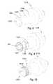
- FIG. 10illustrates a pick assembly 101 G having threads 1010 on a distal end 120 G of a shank 102 G.
- the shank 102 Gmay be inserted into the holder's bore by turning the pick assembly 101 G with a wrench or similar tool.
- the shank 102 Gmay resiliently collapse as the parts are threaded together.
- the holder's boremay have internal threads to connect with the threads 1010 on the shank 102 G.
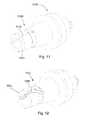
- FIG. 11illustrates a pick assembly 101 H having tapered slots 1110 on a distal end 120 H of a shank 102 H.
- the taperingmay increase outwardly as the taper extends towards the distal end 120 H. Such tapering may allow more flexibility to the portion of the shank 102 H proximate the distal end 120 H.
- FIG. 12illustrates slots 1200 arranged spirally with respect to a center of a shank 102 J.
- the embodiment of FIG. 12may allow more flexibility to a portion of the shank 102 J proximate a distal end 120 J.
- FIGS. 13 a - eillustrate different cross sections of shanks proximate a distal end.
- FIG. 13 aillustrates a shank 102 K having 3 slots 1301 and a circular bore 204 K.
- FIG. 13 billustrates a shank 102 L having 4 wedge shaped slots 1302 and a bore 204 L resembling a square.
- FIG. 13 cillustrates a shank 102 M having 6 slots 1303 and a hexagonal bore 204 M.
- FIG. 13 dillustrates a shank 102 N with recesses 1320 formed on an outer surface 1321 of the shank 102 N and recesses 1322 formed on an inner surface 1323 of the shank.
- FIG. 13 eillustrates a shank 102 P with four recesses 1311 formed on an outer surface 1312 of the shank 102 P and recesses 1313 formed on an inner surface 1314 of the shank 102 P.
- Embodiments of a pick assemblymay be used in many different applications.
- Pick assembly 101 Qmay be a pick in an asphalt milling machine 1400 , as in the embodiment of FIG. 14 .
- a pick assembly 101 Rmay be an insert in a drill bit, as in the embodiments of FIGS. 15-17 . As illustrated in FIG. 15 , pick assembly 101 R may be useful in roller cone bits 1500 , where inserts typically fail the formation through compression. In some embodiments, pick assemblies may be angled to enlarge the gauge well bore.
- FIG. 16discloses a mining bit 1600 having a pick assembly 101 S.
- FIG. 17discloses a drill bit 1700 having a pick assembly 101 T typically used in horizontal drilling.
- FIG. 18illustrates an embodiment where a pick assembly 101 U may be used in a trenching machine 1800 .
- the pick assemblies 101 Umay be placed on a chain that rotates around a boom 1850 .
- Crushing or degradation machinesmay also incorporate the present invention.
- the crushing or degradation machinesmay be used for size reduction in materials such as rocks, grain, trash, natural resources, chalk, wood, tires, metal, cars, tables, couches, coal, minerals, and chemicals.
- chisels 1900may also incorporate a pick assembly 101 V on an impacting end 1950 V.
- pick assembly 101 Wis located on an impacting end 1950 W of a moil 2000 .
- FIG. 21discloses a mining machine 2100 .
- Pick assemblies 101 Xmay be connected to a rotating drum 2110 while degrading mineral or coal formations 2120 .
- the rotating drum 2110is connected to an arm 2150 that moves the drum 2110 vertically in order to engage the formation 2120 .
- the arm 2150may move by a hydraulic arm 2180 , which may also pivot about an axis.
- the mining machine 2100may move about by tracks, wheels, or a combination thereof.
- the mining machine 2100may also move about in a subterranean formation.
Landscapes
- Engineering & Computer Science (AREA)
- Mining & Mineral Resources (AREA)
- Mechanical Engineering (AREA)
- Life Sciences & Earth Sciences (AREA)
- General Life Sciences & Earth Sciences (AREA)
- Geochemistry & Mineralogy (AREA)
- Geology (AREA)
- Drilling And Exploitation, And Mining Machines And Methods (AREA)
Abstract
Description
Claims (8)
Priority Applications (1)
| Application Number | Priority Date | Filing Date | Title |
|---|---|---|---|
| US12/491,897US8500210B2 (en) | 2006-08-11 | 2009-06-25 | Resilient pick shank |
Applications Claiming Priority (28)
| Application Number | Priority Date | Filing Date | Title |
|---|---|---|---|
| US11/463,975US7445294B2 (en) | 2006-08-11 | 2006-08-11 | Attack tool |
| US11/463,998US7384105B2 (en) | 2006-08-11 | 2006-08-11 | Attack tool |
| US11/463,990US7320505B1 (en) | 2006-08-11 | 2006-08-11 | Attack tool |
| US11/463,953US7464993B2 (en) | 2006-08-11 | 2006-08-11 | Attack tool |
| US11/464,008US7338135B1 (en) | 2006-08-11 | 2006-08-11 | Holder for a degradation assembly |
| US11/463,962US7413256B2 (en) | 2006-08-11 | 2006-08-11 | Washer for a degradation assembly |
| US11/686,831US7568770B2 (en) | 2006-06-16 | 2007-03-15 | Superhard composite material bonded to a steel body |
| US11/695,672US7396086B1 (en) | 2007-03-15 | 2007-04-03 | Press-fit pick |
| US11/742,261US7469971B2 (en) | 2006-08-11 | 2007-04-30 | Lubricated pick |
| US11/742,304US7475948B2 (en) | 2006-08-11 | 2007-04-30 | Pick with a bearing |
| US76686507A | 2007-06-22 | 2007-06-22 | |
| US11/766,903US20130341999A1 (en) | 2006-08-11 | 2007-06-22 | Attack Tool with an Interruption |
| US11/773,271US7997661B2 (en) | 2006-08-11 | 2007-07-03 | Tapered bore in a pick |
| US11/829,761US7722127B2 (en) | 2006-08-11 | 2007-07-27 | Pick shank in axial tension |
| US11/844,586US7600823B2 (en) | 2006-08-11 | 2007-08-24 | Pick assembly |
| US11/947,644US8007051B2 (en) | 2006-08-11 | 2007-11-29 | Shank assembly |
| US11/962,497US8292372B2 (en) | 2007-12-21 | 2007-12-21 | Retention for holder shank |
| US11/971,965US7648210B2 (en) | 2006-08-11 | 2008-01-10 | Pick with an interlocked bolster |
| US12/021,051US8123302B2 (en) | 2006-08-11 | 2008-01-28 | Impact tool |
| US12/021,019US8485609B2 (en) | 2006-08-11 | 2008-01-28 | Impact tool |
| US12/051,689US7963617B2 (en) | 2006-08-11 | 2008-03-19 | Degradation assembly |
| US12/051,586US8007050B2 (en) | 2006-08-11 | 2008-03-19 | Degradation assembly |
| US12/051,738US7669674B2 (en) | 2006-08-11 | 2008-03-19 | Degradation assembly |
| US12/112,743US8029068B2 (en) | 2006-08-11 | 2008-04-30 | Locking fixture for a degradation assembly |
| US12/135,595US7946656B2 (en) | 2006-08-11 | 2008-06-09 | Retention system |
| US12/177,556US7635168B2 (en) | 2006-08-11 | 2008-07-22 | Degradation assembly shield |
| US12/491,897US8500210B2 (en) | 2006-08-11 | 2009-06-25 | Resilient pick shank |
| US12/491,848US8118371B2 (en) | 2006-08-11 | 2009-06-25 | Resilient pick shank |
Related Parent Applications (2)
| Application Number | Title | Priority Date | Filing Date |
|---|---|---|---|
| US11/695,672Continuation-In-PartUS7396086B1 (en) | 2006-08-11 | 2007-04-03 | Press-fit pick |
| US12/491,848ContinuationUS8118371B2 (en) | 2006-08-11 | 2009-06-25 | Resilient pick shank |
Related Child Applications (1)
| Application Number | Title | Priority Date | Filing Date |
|---|---|---|---|
| US11/463,975Continuation-In-PartUS7445294B2 (en) | 2006-08-11 | 2006-08-11 | Attack tool |
Publications (2)
| Publication Number | Publication Date |
|---|---|
| US20090267403A1 US20090267403A1 (en) | 2009-10-29 |
| US8500210B2true US8500210B2 (en) | 2013-08-06 |
Family
ID=41256638
Family Applications (2)
| Application Number | Title | Priority Date | Filing Date |
|---|---|---|---|
| US12/491,897Active2028-04-04US8500210B2 (en) | 2006-08-11 | 2009-06-25 | Resilient pick shank |
| US12/491,848Active2027-05-09US8118371B2 (en) | 2006-08-11 | 2009-06-25 | Resilient pick shank |
Family Applications After (1)
| Application Number | Title | Priority Date | Filing Date |
|---|---|---|---|
| US12/491,848Active2027-05-09US8118371B2 (en) | 2006-08-11 | 2009-06-25 | Resilient pick shank |
Country Status (1)
| Country | Link |
|---|---|
| US (2) | US8500210B2 (en) |
Cited By (1)
| Publication number | Priority date | Publication date | Assignee | Title |
|---|---|---|---|---|
| US10590710B2 (en) | 2016-12-09 | 2020-03-17 | Baker Hughes, A Ge Company, Llc | Cutting elements, earth-boring tools including the cutting elements, and methods of forming the cutting elements |
Families Citing this family (53)
| Publication number | Priority date | Publication date | Assignee | Title |
|---|---|---|---|---|
| US7959234B2 (en)* | 2008-03-15 | 2011-06-14 | Kennametal Inc. | Rotatable cutting tool with superhard cutting member |
| GB0912022D0 (en)* | 2009-07-10 | 2009-08-19 | Element Six Holding Gmbh | Attack tool assembly |
| US8727357B2 (en)* | 2009-11-25 | 2014-05-20 | Kennametal Inc. | Toolholder secondary retention system |
| US9028009B2 (en) | 2010-01-20 | 2015-05-12 | Element Six Gmbh | Pick tool and method for making same |
| US10598013B2 (en) | 2010-08-27 | 2020-03-24 | The Sollami Company | Bit holder with shortened nose portion |
| US10385689B1 (en) | 2010-08-27 | 2019-08-20 | The Sollami Company | Bit holder |
| US10072501B2 (en) | 2010-08-27 | 2018-09-11 | The Sollami Company | Bit holder |
| US9879531B2 (en) | 2014-02-26 | 2018-01-30 | The Sollami Company | Bit holder shank and differential interference between the shank distal portion and the bit holder block bore |
| US11261731B1 (en) | 2014-04-23 | 2022-03-01 | The Sollami Company | Bit holder and unitary bit/holder for use in shortened depth base blocks |
| US10337324B2 (en) | 2015-01-07 | 2019-07-02 | The Sollami Company | Various bit holders and unitary bit/holders for use with shortened depth bit holder blocks |
| ZA201108667B (en) | 2010-11-30 | 2012-07-25 | Harnischfeger Tech Inc | Pick holder |
| GB201118739D0 (en) | 2011-10-31 | 2011-12-14 | Element Six Abrasives Sa | Tip for a pick tool, method of making same and pick tool comprising same |
| USD709112S1 (en) | 2011-11-30 | 2014-07-15 | Harnischfeger Technologies, Inc. | Pick holder |
| USD720375S1 (en) | 2011-11-30 | 2014-12-30 | Harnischfeger Technologies, Inc. | Pick holder |
| US9988903B2 (en) | 2012-10-19 | 2018-06-05 | The Sollami Company | Combination polycrystalline diamond bit and bit holder |
| US10105870B1 (en) | 2012-10-19 | 2018-10-23 | The Sollami Company | Combination polycrystalline diamond bit and bit holder |
| US9909416B1 (en) | 2013-09-18 | 2018-03-06 | The Sollami Company | Diamond tipped unitary holder/bit |
| US10107097B1 (en) | 2012-10-19 | 2018-10-23 | The Sollami Company | Combination polycrystalline diamond bit and bit holder |
| US10260342B1 (en) | 2012-10-19 | 2019-04-16 | The Sollami Company | Combination polycrystalline diamond bit and bit holder |
| US10180065B1 (en) | 2015-10-05 | 2019-01-15 | The Sollami Company | Material removing tool for road milling mining and trenching operations |
| US10323515B1 (en) | 2012-10-19 | 2019-06-18 | The Sollami Company | Tool with steel sleeve member |
| EP2740884B1 (en)* | 2012-12-06 | 2015-02-25 | Sandvik Intellectual Property AB | Rock bit tip and rock bit |
| US10767478B2 (en) | 2013-09-18 | 2020-09-08 | The Sollami Company | Diamond tipped unitary holder/bit |
| US10794181B2 (en) | 2014-04-02 | 2020-10-06 | The Sollami Company | Bit/holder with enlarged ballistic tip insert |
| US10577931B2 (en) | 2016-03-05 | 2020-03-03 | The Sollami Company | Bit holder (pick) with shortened shank and angular differential between the shank and base block bore |
| US10633971B2 (en) | 2016-03-07 | 2020-04-28 | The Sollami Company | Bit holder with enlarged tire portion and narrowed bit holder block |
| US10968739B1 (en) | 2013-09-18 | 2021-04-06 | The Sollami Company | Diamond tipped unitary holder/bit |
| US10947844B1 (en) | 2013-09-18 | 2021-03-16 | The Sollami Company | Diamond Tipped Unitary Holder/Bit |
| US9976418B2 (en) | 2014-04-02 | 2018-05-22 | The Sollami Company | Bit/holder with enlarged ballistic tip insert |
| US10995613B1 (en) | 2013-09-18 | 2021-05-04 | The Sollami Company | Diamond tipped unitary holder/bit |
| US10876402B2 (en) | 2014-04-02 | 2020-12-29 | The Sollami Company | Bit tip insert |
| US10415386B1 (en) | 2013-09-18 | 2019-09-17 | The Sollami Company | Insertion-removal tool for holder/bit |
| US11168563B1 (en) | 2013-10-16 | 2021-11-09 | The Sollami Company | Bit holder with differential interference |
| GB201320501D0 (en)* | 2013-11-20 | 2014-01-01 | Element Six Gmbh | Strike constructions,picks comprising same and methods for making same |
| US11339656B1 (en) | 2014-02-26 | 2022-05-24 | The Sollami Company | Rear of base block |
| US11339654B2 (en) | 2014-04-02 | 2022-05-24 | The Sollami Company | Insert with heat transfer bore |
| US11891895B1 (en) | 2014-04-23 | 2024-02-06 | The Sollami Company | Bit holder with annular rings |
| USD775247S1 (en)* | 2015-01-22 | 2016-12-27 | Betek Gmbh & Co. Kg | Flat chisel |
| US10502056B2 (en) | 2015-09-30 | 2019-12-10 | The Sollami Company | Reverse taper shanks and complementary base block bores for bit assemblies |
| US10107098B2 (en) | 2016-03-15 | 2018-10-23 | The Sollami Company | Bore wear compensating bit holder and bit holder block |
| US10612376B1 (en) | 2016-03-15 | 2020-04-07 | The Sollami Company | Bore wear compensating retainer and washer |
| US10612375B2 (en) | 2016-04-01 | 2020-04-07 | The Sollami Company | Bit retainer |
| US10876401B1 (en) | 2016-07-26 | 2020-12-29 | The Sollami Company | Rotational style tool bit assembly |
| US11187080B2 (en) | 2018-04-24 | 2021-11-30 | The Sollami Company | Conical bit with diamond insert |
| US10968738B1 (en) | 2017-03-24 | 2021-04-06 | The Sollami Company | Remanufactured conical bit |
| US10233751B2 (en)* | 2017-04-18 | 2019-03-19 | Caterpillar Paving Products Inc. | Tool adapter for a rotary tool |
| US11279012B1 (en) | 2017-09-15 | 2022-03-22 | The Sollami Company | Retainer insertion and extraction tool |
| US11103939B2 (en) | 2018-07-18 | 2021-08-31 | The Sollami Company | Rotatable bit cartridge |
| EP3597855A1 (en) | 2018-07-18 | 2020-01-22 | The Sollami Company | Diamond tipped unitary holder/bit |
| WO2020220066A1 (en)* | 2019-04-30 | 2020-11-05 | Idim Pty Ltd | Tool holder assembly |
| US12345158B1 (en) | 2019-06-20 | 2025-07-01 | The Sollami Company | Bit tip insert |
| DE102019008156A1 (en)* | 2019-06-28 | 2020-12-31 | Bomag Gmbh | Milling chisel for a floor milling machine, assembly unit with such a milling chisel and a clamping screw, chisel holder, chisel holder system, milling drum and floor milling machine as well as a method for assembling a milling chisel in a chisel holder |
| US12227907B2 (en)* | 2021-03-13 | 2025-02-18 | Jeffrey L. Rule, Sr. | Milling tool |
Citations (151)
| Publication number | Priority date | Publication date | Assignee | Title |
|---|---|---|---|---|
| US2004315A (en) | 1932-08-29 | 1935-06-11 | Thomas R Mcdonald | Packing liner |
| US2124438A (en) | 1935-04-05 | 1938-07-19 | Gen Electric | Soldered article or machine part |
| US3254392A (en) | 1963-11-13 | 1966-06-07 | Warner Swasey Co | Insert bit for cutoff and like tools |
| US3336081A (en)* | 1965-08-02 | 1967-08-15 | Samuel S Ericsson | Percussion tool with replaceable point |
| US3342531A (en) | 1965-02-16 | 1967-09-19 | Cincinnati Mine Machinery Co | Conical cutter bits held by resilient retainer for free rotation |
| US3342532A (en) | 1965-03-15 | 1967-09-19 | Cincinnati Mine Machinery Co | Cutting tool comprising holder freely rotatable in socket with bit frictionally attached |
| US3397012A (en) | 1966-12-19 | 1968-08-13 | Cincinnati Mine Machinery Co | Cutter bits and means for mounting them |
| US3745396A (en) | 1972-05-25 | 1973-07-10 | Energy Sciences Inc | Elongated electron-emission cathode assembly and method |
| US3746396A (en) | 1970-12-31 | 1973-07-17 | Continental Oil Co | Cutter bit and method of causing rotation thereof |
| US3801158A (en) | 1972-10-25 | 1974-04-02 | Continental Oil Co | Rotating hub assembly for a mining cutter bit |
| US3807804A (en) | 1972-09-12 | 1974-04-30 | Kennametal Inc | Impacting tool with tungsten carbide insert tip |
| US3820848A (en) | 1973-04-02 | 1974-06-28 | Kennametal Inc | Rotary mining tool and keeper arrangement therefor |
| US3830321A (en) | 1973-02-20 | 1974-08-20 | Kennametal Inc | Excavating tool and a bit for use therewith |
| US3865437A (en) | 1973-08-16 | 1975-02-11 | Kennametal Inc | Rotary mining tool retaining structure |
| US3932952A (en) | 1973-12-17 | 1976-01-20 | Caterpillar Tractor Co. | Multi-material ripper tip |
| US3942838A (en) | 1974-05-31 | 1976-03-09 | Joy Manufacturing Company | Bit coupling means |
| US3945681A (en) | 1973-12-07 | 1976-03-23 | Western Rock Bit Company Limited | Cutter assembly |
| US4005914A (en) | 1974-08-20 | 1977-02-01 | Rolls-Royce (1971) Limited | Surface coating for machine elements having rubbing surfaces |
| US4006936A (en) | 1975-11-06 | 1977-02-08 | Dresser Industries, Inc. | Rotary cutter for a road planer |
| US4084856A (en) | 1976-02-09 | 1978-04-18 | Fansteel Inc. | Self-retaining sleeve and bit |
| US4098362A (en) | 1976-11-30 | 1978-07-04 | General Electric Company | Rotary drill bit and method for making same |
| US4109737A (en) | 1976-06-24 | 1978-08-29 | General Electric Company | Rotary drill bit |
| GB2004315A (en) | 1977-09-17 | 1979-03-28 | Krupp Gmbh | Tool for cutting rocks and minerals. |
| US4149753A (en) | 1976-07-06 | 1979-04-17 | Gewerkschaft Eisenhutte Westfalia | Cutter bit assemblies |
| US4156329A (en) | 1977-05-13 | 1979-05-29 | General Electric Company | Method for fabricating a rotary drill bit and composite compact cutters therefor |
| US4199035A (en) | 1978-04-24 | 1980-04-22 | General Electric Company | Cutting and drilling apparatus with threadably attached compacts |
| US4201421A (en) | 1978-09-20 | 1980-05-06 | Besten Leroy E Den | Mining machine bit and mounting thereof |
| US4251109A (en)* | 1979-10-03 | 1981-02-17 | The United States Of America As Represented By The Secretary Of The Interior | Dust controlling method using a coal cutter bit |
| US4277106A (en) | 1979-10-22 | 1981-07-07 | Syndrill Carbide Diamond Company | Self renewing working tip mining pick |
| US4289211A (en) | 1977-03-03 | 1981-09-15 | Sandvik Aktiebolag | Rock drill bit |
| GB2037223B (en) | 1978-11-28 | 1982-10-06 | Wirtgen Reinhard | Milling cutter for a milling device |
| US4439250A (en) | 1983-06-09 | 1984-03-27 | International Business Machines Corporation | Solder/braze-stop composition |
| US4465221A (en) | 1982-09-28 | 1984-08-14 | Schmidt Glenn H | Method of sustaining metallic golf club head sole plate profile by confined brazing or welding |
| DE3307910A1 (en) | 1983-03-05 | 1984-09-27 | Fried. Krupp Gmbh, 4300 Essen | Tool arrangement with a round-shank cutter |
| US4484644A (en) | 1980-09-02 | 1984-11-27 | Ingersoll-Rand Company | Sintered and forged article, and method of forming same |
| US4489986A (en) | 1982-11-01 | 1984-12-25 | Dziak William A | Wear collar device for rotatable cutter bit |
| US4573744A (en) | 1980-11-24 | 1986-03-04 | Padley & Venables Limited | Pick and the combination of a pick and holder |
| US4583786A (en)* | 1983-03-02 | 1986-04-22 | Padley & Venables Limited | Mineral mining pick and holder assembly |
| DE3500261C2 (en) | 1985-01-05 | 1987-01-29 | Bergwerksverband Gmbh, 4300 Essen | Chisels for cutting mineral raw materials |
| US4657308A (en) | 1985-02-22 | 1987-04-14 | Hall & Pickles Limited | Mineral cutter pick |
| US4669786A (en) | 1985-08-05 | 1987-06-02 | Morgan Vernon B | Core breaker |
| US4678237A (en) | 1982-08-06 | 1987-07-07 | Huddy Diamond Crown Setting Company (Proprietary) Limited | Cutter inserts for picks |
| US4682987A (en) | 1981-04-16 | 1987-07-28 | Brady William J | Method and composition for producing hard surface carbide insert tools |
| US4688856A (en) | 1984-10-27 | 1987-08-25 | Gerd Elfgen | Round cutting tool |
| US4725098A (en) | 1986-12-19 | 1988-02-16 | Kennametal Inc. | Erosion resistant cutting bit with hardfacing |
| US4729603A (en) | 1984-11-22 | 1988-03-08 | Gerd Elfgen | Round cutting tool for cutters |
| US4765687A (en) | 1986-02-19 | 1988-08-23 | Innovation Limited | Tip and mineral cutter pick |
| US4765686A (en) | 1987-10-01 | 1988-08-23 | Gte Valenite Corporation | Rotatable cutting bit for a mining machine |
| US4776862A (en) | 1987-12-08 | 1988-10-11 | Wiand Ronald C | Brazing of diamond |
| US4880154A (en) | 1986-04-03 | 1989-11-14 | Klaus Tank | Brazing |
| DE3818213A1 (en) | 1988-05-28 | 1989-11-30 | Gewerk Eisenhuette Westfalia | Pick, in particular for underground winning machines, heading machines and the like |
| US4932723A (en) | 1989-06-29 | 1990-06-12 | Mills Ronald D | Cutting-bit holding support block shield |
| US4940288A (en) | 1988-07-20 | 1990-07-10 | Kennametal Inc. | Earth engaging cutter bit |
| US4944559A (en) | 1988-06-02 | 1990-07-31 | Societe Industrielle De Combustible Nucleaire | Tool for a mine working machine comprising a diamond-charged abrasive component |
| US4951762A (en) | 1988-07-28 | 1990-08-28 | Sandvik Ab | Drill bit with cemented carbide inserts |
| US4956238A (en)* | 1987-06-12 | 1990-09-11 | Reed Tool Company Limited | Manufacture of cutting structures for rotary drill bits |
| EP0412287A2 (en) | 1989-08-11 | 1991-02-13 | VERSCHLEISS-TECHNIK DR.-ING. HANS WAHL GMBH & CO. | Pick or similar tool for the extraction of raw materials or the recycling |
| US5011515A (en) | 1989-08-07 | 1991-04-30 | Frushour Robert H | Composite polycrystalline diamond compact with improved impact resistance |
| US5092310A (en) | 1989-05-23 | 1992-03-03 | General Electric Company | Mining pick |
| US5112165A (en) | 1989-04-24 | 1992-05-12 | Sandvik Ab | Tool for cutting solid material |
| US5119714A (en) | 1991-03-01 | 1992-06-09 | Hughes Tool Company | Rotary rock bit with improved diamond filled compacts |
| US5141289A (en) | 1988-07-20 | 1992-08-25 | Kennametal Inc. | Cemented carbide tip |
| US5154245A (en) | 1990-04-19 | 1992-10-13 | Sandvik Ab | Diamond rock tools for percussive and rotary crushing rock drilling |
| US5186892A (en) | 1991-01-17 | 1993-02-16 | U.S. Synthetic Corporation | Method of healing cracks and flaws in a previously sintered cemented carbide tools |
| US5235961A (en) | 1991-10-19 | 1993-08-17 | Hydra Tools International Plc | Carbide tip and pick |
| US5251964A (en) | 1992-08-03 | 1993-10-12 | Gte Valenite Corporation | Cutting bit mount having carbide inserts and method for mounting the same |
| DE4039217C2 (en) | 1990-12-08 | 1993-11-11 | Willi Jacobs | Picks |
| US5261499A (en) | 1992-07-15 | 1993-11-16 | Kennametal Inc. | Two-piece rotatable cutting bit |
| US5319855A (en) | 1991-11-30 | 1994-06-14 | Hydra Tools International Plc | Mineral cutter tip and pick |
| US5332348A (en) | 1987-03-31 | 1994-07-26 | Lemelson Jerome H | Fastening devices |
| US5417475A (en) | 1992-08-19 | 1995-05-23 | Sandvik Ab | Tool comprised of a holder body and a hard insert and method of using same |
| US5447208A (en) | 1993-11-22 | 1995-09-05 | Baker Hughes Incorporated | Superhard cutting element having reduced surface roughness and method of modifying |
| US5535839A (en) | 1995-06-07 | 1996-07-16 | Brady; William J. | Roof drill bit with radial domed PCD inserts |
| US5542993A (en) | 1989-10-10 | 1996-08-06 | Alliedsignal Inc. | Low melting nickel-palladium-silicon brazing alloy |
| US5725283A (en) | 1996-04-16 | 1998-03-10 | Joy Mm Delaware, Inc. | Apparatus for holding a cutting bit |
| US5738698A (en) | 1994-07-29 | 1998-04-14 | Saint Gobain/Norton Company Industrial Ceramics Corp. | Brazing of diamond film to tungsten carbide |
| US5823632A (en) | 1996-06-13 | 1998-10-20 | Burkett; Kenneth H. | Self-sharpening nosepiece with skirt for attack tools |
| US5837071A (en) | 1993-11-03 | 1998-11-17 | Sandvik Ab | Diamond coated cutting tool insert and method of making same |
| US5842747A (en) | 1997-02-24 | 1998-12-01 | Keystone Engineering & Manufacturing Corporation | Apparatus for roadway surface reclaiming drum |
| US5845547A (en) | 1996-09-09 | 1998-12-08 | The Sollami Company | Tool having a tungsten carbide insert |
| US5875862A (en) | 1995-07-14 | 1999-03-02 | U.S. Synthetic Corporation | Polycrystalline diamond cutter with integral carbide/diamond transition layer |
| US5890552A (en) | 1992-01-31 | 1999-04-06 | Baker Hughes Incorporated | Superabrasive-tipped inserts for earth-boring drill bits |
| US5934542A (en) | 1994-03-31 | 1999-08-10 | Sumitomo Electric Industries, Inc. | High strength bonding tool and a process for production of the same |
| US5935718A (en) | 1994-11-07 | 1999-08-10 | General Electric Company | Braze blocking insert for liquid phase brazing operation |
| US5944129A (en) | 1997-11-28 | 1999-08-31 | U.S. Synthetic Corporation | Surface finish for non-planar inserts |
| US5992405A (en) | 1998-01-02 | 1999-11-30 | The Sollami Company | Tool mounting for a cutting tool |
| US6006846A (en) | 1997-09-19 | 1999-12-28 | Baker Hughes Incorporated | Cutting element, drill bit, system and method for drilling soft plastic formations |
| US6019434A (en) | 1997-10-07 | 2000-02-01 | Fansteel Inc. | Point attack bit |
| US6044920A (en) | 1997-07-15 | 2000-04-04 | Kennametal Inc. | Rotatable cutting bit assembly with cutting inserts |
| US6056911A (en) | 1998-05-27 | 2000-05-02 | Camco International (Uk) Limited | Methods of treating preform elements including polycrystalline diamond bonded to a substrate |
| US6059373A (en) | 1995-04-06 | 2000-05-09 | Kennametal Inc. | Pick holder extraction |
| US6065552A (en) | 1998-07-20 | 2000-05-23 | Baker Hughes Incorporated | Cutting elements with binderless carbide layer |
| US6068072A (en) | 1998-02-09 | 2000-05-30 | Diamond Products International, Inc. | Cutting element |
| US6099081A (en) | 1997-09-06 | 2000-08-08 | Hydra Tools International Limited | Point attack tooling system for mineral winning |
| US6102486A (en) | 1997-07-31 | 2000-08-15 | Briese Industrial Technologies, Inc. | Frustum cutting bit arrangement |
| US6113195A (en) | 1998-10-08 | 2000-09-05 | Sandvik Ab | Rotatable cutting bit and bit washer therefor |
| US6170917B1 (en) | 1997-08-27 | 2001-01-09 | Kennametal Inc. | Pick-style tool with a cermet insert having a Co-Ni-Fe-binder |
| US6193770B1 (en) | 1997-04-04 | 2001-02-27 | Chien-Min Sung | Brazed diamond tools by infiltration |
| US6196910B1 (en) | 1998-08-10 | 2001-03-06 | General Electric Company | Polycrystalline diamond compact cutter with improved cutting by preventing chip build up |
| US6196636B1 (en) | 1999-03-22 | 2001-03-06 | Larry J. McSweeney | Cutting bit insert configured in a polygonal pyramid shape and having a ring mounted in surrounding relationship with the insert |
| US6199956B1 (en) | 1998-01-28 | 2001-03-13 | Betek Bergbau- Und Hartmetalltechnik Karl-Heinz-Simon Gmbh & Co. Kg | Round-shank bit for a coal cutting machine |
| US6216805B1 (en) | 1999-07-12 | 2001-04-17 | Baker Hughes Incorporated | Dual grade carbide substrate for earth-boring drill bit cutting elements, drill bits so equipped, and methods |
| US6270165B1 (en) | 1999-10-22 | 2001-08-07 | Sandvik Rock Tools, Inc. | Cutting tool for breaking hard material, and a cutting cap therefor |
| US6331035B1 (en) | 1999-03-19 | 2001-12-18 | Kennametal Pc Inc. | Cutting tool holder assembly with press fit |
| US6341823B1 (en) | 2000-05-22 | 2002-01-29 | The Sollami Company | Rotatable cutting tool with notched radial fins |
| DE19821147C2 (en) | 1998-05-12 | 2002-02-07 | Betek Bergbau & Hartmetall | Attack cutting tools |
| US6354771B1 (en) | 1998-12-12 | 2002-03-12 | Boart Longyear Gmbh & Co. Kg | Cutting or breaking tool as well as cutting insert for the latter |
| US6364420B1 (en) | 1999-03-22 | 2002-04-02 | The Sollami Company | Bit and bit holder/block having a predetermined area of failure |
| US6371567B1 (en) | 1999-03-22 | 2002-04-16 | The Sollami Company | Bit holders and bit blocks for road milling, mining and trenching equipment |
| US6375272B1 (en) | 2000-03-24 | 2002-04-23 | Kennametal Inc. | Rotatable cutting tool insert |
| US6419278B1 (en) | 2000-05-31 | 2002-07-16 | Dana Corporation | Automotive hose coupling |
| US6478383B1 (en) | 1999-10-18 | 2002-11-12 | Kennametal Pc Inc. | Rotatable cutting tool-tool holder assembly |
| US20020175555A1 (en) | 2001-05-23 | 2002-11-28 | Mercier Greg D. | Rotatable cutting bit and retainer sleeve therefor |
| US6499547B2 (en) | 1999-01-13 | 2002-12-31 | Baker Hughes Incorporated | Multiple grade carbide for diamond capped insert |
| US6517902B2 (en) | 1998-05-27 | 2003-02-11 | Camco International (Uk) Limited | Methods of treating preform elements |
| US20030052530A1 (en)* | 2001-09-18 | 2003-03-20 | Sollami Phillip A. | Hardened tip for cutting tools |
| DE10163717C1 (en) | 2001-12-21 | 2003-05-28 | Betek Bergbau & Hartmetall | Chisel, for a coal cutter, comprises a head having cuttings-receiving pockets arranged a distance apart between the tip and an annular groove and running around the head to form partially concave cuttings-retaining surfaces facing the tip |
| US20030110667A1 (en) | 2000-03-31 | 2003-06-19 | Hiroyuki Adachi | System for determining rental of construction machine |
| US20030140360A1 (en) | 1998-08-17 | 2003-07-24 | The Trustees Of Columbia University In The City Of New York | Transgenic mammals and reagents for improving long-term memory |
| US20030141350A1 (en) | 2002-01-25 | 2003-07-31 | Shinya Noro | Method of applying brazing material |
| US20030209366A1 (en)* | 2002-05-07 | 2003-11-13 | Mcalvain Bruce William | Rotatable point-attack bit with protective body |
| US20030213354A1 (en) | 2002-03-09 | 2003-11-20 | Frers Gerd F. | Cutting tool holder with cutting tool |
| US20030234280A1 (en) | 2002-03-28 | 2003-12-25 | Cadden Charles H. | Braze system and method for reducing strain in a braze joint |
| US6672406B2 (en) | 1997-09-08 | 2004-01-06 | Baker Hughes Incorporated | Multi-aggressiveness cuttting face on PDC cutters and method of drilling subterranean formations |
| US6685273B1 (en) | 2000-02-15 | 2004-02-03 | The Sollami Company | Streamlining bit assemblies for road milling, mining and trenching equipment |
| US20040026983A1 (en) | 2002-08-07 | 2004-02-12 | Mcalvain Bruce William | Monolithic point-attack bit |
| US6692083B2 (en) | 2002-06-14 | 2004-02-17 | Keystone Engineering & Manufacturing Corporation | Replaceable wear surface for bit support |
| US6709065B2 (en) | 2002-01-30 | 2004-03-23 | Sandvik Ab | Rotary cutting bit with material-deflecting ledge |
| US20040065484A1 (en) | 2002-10-08 | 2004-04-08 | Mcalvain Bruce William | Diamond tip point-attack bit |
| US6719074B2 (en) | 2001-03-23 | 2004-04-13 | Japan National Oil Corporation | Insert chip of oil-drilling tricone bit, manufacturing method thereof and oil-drilling tricone bit |
| US6733087B2 (en)* | 2002-08-10 | 2004-05-11 | David R. Hall | Pick for disintegrating natural and man-made materials |
| US6739327B2 (en) | 2001-12-31 | 2004-05-25 | The Sollami Company | Cutting tool with hardened tip having a tapered base |
| US6786557B2 (en) | 2000-12-20 | 2004-09-07 | Kennametal Inc. | Protective wear sleeve having tapered lock and retainer |
| US6824225B2 (en) | 2001-09-10 | 2004-11-30 | Kennametal Inc. | Embossed washer |
| US6846045B2 (en) | 2002-04-12 | 2005-01-25 | The Sollami Company | Reverse taper cutting tip with a collar |
| US6851758B2 (en) | 2002-12-20 | 2005-02-08 | Kennametal Inc. | Rotatable bit having a resilient retainer sleeve with clearance |
| US6854810B2 (en) | 2000-12-20 | 2005-02-15 | Kennametal Inc. | T-shaped cutter tool assembly with wear sleeve |
| US20050035649A1 (en) | 2003-08-15 | 2005-02-17 | Sandvik Ab | Rotary cutting bit with material-deflecting ledge |
| US6861137B2 (en) | 2000-09-20 | 2005-03-01 | Reedhycalog Uk Ltd | High volume density polycrystalline diamond with working surfaces depleted of catalyzing material |
| US6889890B2 (en) | 2001-10-09 | 2005-05-10 | Hohoemi Brains, Inc. | Brazing-filler material and method for brazing diamond |
| US6918636B2 (en) | 2000-08-07 | 2005-07-19 | Age Mining Services Pty Ltd | Coal and rock cutting pick |
| US20050159840A1 (en) | 2004-01-16 | 2005-07-21 | Wen-Jong Lin | System for surface finishing a workpiece |
| US20050173966A1 (en) | 2004-02-06 | 2005-08-11 | Mouthaan Daniel J. | Non-rotatable protective member, cutting tool using the protective member, and cutting tool assembly using the protective member |
| US6938961B2 (en) | 2002-03-21 | 2005-09-06 | Cutting Edge Technologies, Llc | Apparatus for breaking up solid objects |
| US6966611B1 (en) | 2002-01-24 | 2005-11-22 | The Sollami Company | Rotatable tool assembly |
| US20060086540A1 (en) | 2004-10-23 | 2006-04-27 | Griffin Nigel D | Dual-Edge Working Surfaces for Polycrystalline Diamond Cutting Elements |
| US20060237236A1 (en) | 2005-04-26 | 2006-10-26 | Harold Sreshta | Composite structure having a non-planar interface and method of making same |
| US20070013224A1 (en) | 2005-02-18 | 2007-01-18 | Sandvik Intellectual Property Ab. | Tool holder block and sleeve retained therein by interference fit |
| US7350601B2 (en) | 2005-01-25 | 2008-04-01 | Smith International, Inc. | Cutting elements formed from ultra hard materials having an enhanced construction |
| US7669938B2 (en) | 2006-08-11 | 2010-03-02 | Hall David R | Carbide stem press fit into a steel body of a pick |
| US7992945B2 (en)* | 2006-08-11 | 2011-08-09 | Schlumberger Technology Corporation | Hollow pick shank |
Family Cites Families (6)
| Publication number | Priority date | Publication date | Assignee | Title |
|---|---|---|---|---|
| US2124435A (en)* | 1936-08-13 | 1938-07-19 | Gen Electric | Elastic fluid engine control |
| BE789030A (en)* | 1971-03-08 | 1973-01-15 | Caterpillar Tractor Co | Compact hydraulic system to switch a transmission from one state to another. |
| US5006846A (en)* | 1987-11-12 | 1991-04-09 | Granville J Michael | Power transmission line monitoring system |
| AU718453B2 (en)* | 1996-07-17 | 2000-04-13 | Sony Corporation | Image coding and decoding using mapping coefficients corresponding to class information of pixel blocks |
| US6199955B1 (en)* | 1999-01-07 | 2001-03-13 | Thurston Mfg. Co. | Side dump body |
| US7369743B2 (en)* | 2002-01-24 | 2008-05-06 | Lsi Logic Corporation | Enhanced personal video recorder |
- 2009
- 2009-06-25USUS12/491,897patent/US8500210B2/enactiveActive
- 2009-06-25USUS12/491,848patent/US8118371B2/enactiveActive
Patent Citations (164)
| Publication number | Priority date | Publication date | Assignee | Title |
|---|---|---|---|---|
| US2004315A (en) | 1932-08-29 | 1935-06-11 | Thomas R Mcdonald | Packing liner |
| US2124438A (en) | 1935-04-05 | 1938-07-19 | Gen Electric | Soldered article or machine part |
| US3254392A (en) | 1963-11-13 | 1966-06-07 | Warner Swasey Co | Insert bit for cutoff and like tools |
| US3342531A (en) | 1965-02-16 | 1967-09-19 | Cincinnati Mine Machinery Co | Conical cutter bits held by resilient retainer for free rotation |
| US3342532A (en) | 1965-03-15 | 1967-09-19 | Cincinnati Mine Machinery Co | Cutting tool comprising holder freely rotatable in socket with bit frictionally attached |
| US3336081A (en)* | 1965-08-02 | 1967-08-15 | Samuel S Ericsson | Percussion tool with replaceable point |
| US3397012A (en) | 1966-12-19 | 1968-08-13 | Cincinnati Mine Machinery Co | Cutter bits and means for mounting them |
| US3746396A (en) | 1970-12-31 | 1973-07-17 | Continental Oil Co | Cutter bit and method of causing rotation thereof |
| US3745396A (en) | 1972-05-25 | 1973-07-10 | Energy Sciences Inc | Elongated electron-emission cathode assembly and method |
| US3807804A (en) | 1972-09-12 | 1974-04-30 | Kennametal Inc | Impacting tool with tungsten carbide insert tip |
| US3801158A (en) | 1972-10-25 | 1974-04-02 | Continental Oil Co | Rotating hub assembly for a mining cutter bit |
| US3830321A (en) | 1973-02-20 | 1974-08-20 | Kennametal Inc | Excavating tool and a bit for use therewith |
| US3820848A (en) | 1973-04-02 | 1974-06-28 | Kennametal Inc | Rotary mining tool and keeper arrangement therefor |
| US3865437A (en) | 1973-08-16 | 1975-02-11 | Kennametal Inc | Rotary mining tool retaining structure |
| US3945681A (en) | 1973-12-07 | 1976-03-23 | Western Rock Bit Company Limited | Cutter assembly |
| US3932952A (en) | 1973-12-17 | 1976-01-20 | Caterpillar Tractor Co. | Multi-material ripper tip |
| US3942838A (en) | 1974-05-31 | 1976-03-09 | Joy Manufacturing Company | Bit coupling means |
| US4005914A (en) | 1974-08-20 | 1977-02-01 | Rolls-Royce (1971) Limited | Surface coating for machine elements having rubbing surfaces |
| US4006936A (en) | 1975-11-06 | 1977-02-08 | Dresser Industries, Inc. | Rotary cutter for a road planer |
| US4084856A (en) | 1976-02-09 | 1978-04-18 | Fansteel Inc. | Self-retaining sleeve and bit |
| US4109737A (en) | 1976-06-24 | 1978-08-29 | General Electric Company | Rotary drill bit |
| US4149753A (en) | 1976-07-06 | 1979-04-17 | Gewerkschaft Eisenhutte Westfalia | Cutter bit assemblies |
| US4098362A (en) | 1976-11-30 | 1978-07-04 | General Electric Company | Rotary drill bit and method for making same |
| US4289211A (en) | 1977-03-03 | 1981-09-15 | Sandvik Aktiebolag | Rock drill bit |
| US4156329A (en) | 1977-05-13 | 1979-05-29 | General Electric Company | Method for fabricating a rotary drill bit and composite compact cutters therefor |
| GB2004315A (en) | 1977-09-17 | 1979-03-28 | Krupp Gmbh | Tool for cutting rocks and minerals. |
| US4199035A (en) | 1978-04-24 | 1980-04-22 | General Electric Company | Cutting and drilling apparatus with threadably attached compacts |
| US4201421A (en) | 1978-09-20 | 1980-05-06 | Besten Leroy E Den | Mining machine bit and mounting thereof |
| GB2037223B (en) | 1978-11-28 | 1982-10-06 | Wirtgen Reinhard | Milling cutter for a milling device |
| US4251109A (en)* | 1979-10-03 | 1981-02-17 | The United States Of America As Represented By The Secretary Of The Interior | Dust controlling method using a coal cutter bit |
| US4277106A (en) | 1979-10-22 | 1981-07-07 | Syndrill Carbide Diamond Company | Self renewing working tip mining pick |
| US4484644A (en) | 1980-09-02 | 1984-11-27 | Ingersoll-Rand Company | Sintered and forged article, and method of forming same |
| US4573744B1 (en) | 1980-11-24 | 1989-07-25 | ||
| US4573744A (en) | 1980-11-24 | 1986-03-04 | Padley & Venables Limited | Pick and the combination of a pick and holder |
| US4682987A (en) | 1981-04-16 | 1987-07-28 | Brady William J | Method and composition for producing hard surface carbide insert tools |
| US4678237A (en) | 1982-08-06 | 1987-07-07 | Huddy Diamond Crown Setting Company (Proprietary) Limited | Cutter inserts for picks |
| US4465221A (en) | 1982-09-28 | 1984-08-14 | Schmidt Glenn H | Method of sustaining metallic golf club head sole plate profile by confined brazing or welding |
| US4489986A (en) | 1982-11-01 | 1984-12-25 | Dziak William A | Wear collar device for rotatable cutter bit |
| US4583786A (en)* | 1983-03-02 | 1986-04-22 | Padley & Venables Limited | Mineral mining pick and holder assembly |
| DE3307910A1 (en) | 1983-03-05 | 1984-09-27 | Fried. Krupp Gmbh, 4300 Essen | Tool arrangement with a round-shank cutter |
| US4439250A (en) | 1983-06-09 | 1984-03-27 | International Business Machines Corporation | Solder/braze-stop composition |
| US4688856A (en) | 1984-10-27 | 1987-08-25 | Gerd Elfgen | Round cutting tool |
| US4729603A (en) | 1984-11-22 | 1988-03-08 | Gerd Elfgen | Round cutting tool for cutters |
| DE3500261C2 (en) | 1985-01-05 | 1987-01-29 | Bergwerksverband Gmbh, 4300 Essen | Chisels for cutting mineral raw materials |
| US4657308A (en) | 1985-02-22 | 1987-04-14 | Hall & Pickles Limited | Mineral cutter pick |
| US4669786A (en) | 1985-08-05 | 1987-06-02 | Morgan Vernon B | Core breaker |
| US4765687A (en) | 1986-02-19 | 1988-08-23 | Innovation Limited | Tip and mineral cutter pick |
| US4880154A (en) | 1986-04-03 | 1989-11-14 | Klaus Tank | Brazing |
| US4725098A (en) | 1986-12-19 | 1988-02-16 | Kennametal Inc. | Erosion resistant cutting bit with hardfacing |
| US5332348A (en) | 1987-03-31 | 1994-07-26 | Lemelson Jerome H | Fastening devices |
| US4956238A (en)* | 1987-06-12 | 1990-09-11 | Reed Tool Company Limited | Manufacture of cutting structures for rotary drill bits |
| EP0295151B1 (en) | 1987-06-12 | 1993-07-28 | Camco Drilling Group Limited | Improvements in or relating to the manufacture of cutting elements for rotary drill bits |
| US4765686A (en) | 1987-10-01 | 1988-08-23 | Gte Valenite Corporation | Rotatable cutting bit for a mining machine |
| US4776862A (en) | 1987-12-08 | 1988-10-11 | Wiand Ronald C | Brazing of diamond |
| DE3818213A1 (en) | 1988-05-28 | 1989-11-30 | Gewerk Eisenhuette Westfalia | Pick, in particular for underground winning machines, heading machines and the like |
| US4944559A (en) | 1988-06-02 | 1990-07-31 | Societe Industrielle De Combustible Nucleaire | Tool for a mine working machine comprising a diamond-charged abrasive component |
| US5141289A (en) | 1988-07-20 | 1992-08-25 | Kennametal Inc. | Cemented carbide tip |
| US4940288A (en) | 1988-07-20 | 1990-07-10 | Kennametal Inc. | Earth engaging cutter bit |
| US4951762A (en) | 1988-07-28 | 1990-08-28 | Sandvik Ab | Drill bit with cemented carbide inserts |
| US5112165A (en) | 1989-04-24 | 1992-05-12 | Sandvik Ab | Tool for cutting solid material |
| US5092310A (en) | 1989-05-23 | 1992-03-03 | General Electric Company | Mining pick |
| US4932723A (en) | 1989-06-29 | 1990-06-12 | Mills Ronald D | Cutting-bit holding support block shield |
| US5011515A (en) | 1989-08-07 | 1991-04-30 | Frushour Robert H | Composite polycrystalline diamond compact with improved impact resistance |
| US5011515B1 (en) | 1989-08-07 | 1999-07-06 | Robert H Frushour | Composite polycrystalline diamond compact with improved impact resistance |
| EP0412287A2 (en) | 1989-08-11 | 1991-02-13 | VERSCHLEISS-TECHNIK DR.-ING. HANS WAHL GMBH & CO. | Pick or similar tool for the extraction of raw materials or the recycling |
| US5542993A (en) | 1989-10-10 | 1996-08-06 | Alliedsignal Inc. | Low melting nickel-palladium-silicon brazing alloy |
| US5154245A (en) | 1990-04-19 | 1992-10-13 | Sandvik Ab | Diamond rock tools for percussive and rotary crushing rock drilling |
| DE4039217C2 (en) | 1990-12-08 | 1993-11-11 | Willi Jacobs | Picks |
| US5186892A (en) | 1991-01-17 | 1993-02-16 | U.S. Synthetic Corporation | Method of healing cracks and flaws in a previously sintered cemented carbide tools |
| US5119714A (en) | 1991-03-01 | 1992-06-09 | Hughes Tool Company | Rotary rock bit with improved diamond filled compacts |
| US5235961A (en) | 1991-10-19 | 1993-08-17 | Hydra Tools International Plc | Carbide tip and pick |
| US5319855A (en) | 1991-11-30 | 1994-06-14 | Hydra Tools International Plc | Mineral cutter tip and pick |
| US5890552A (en) | 1992-01-31 | 1999-04-06 | Baker Hughes Incorporated | Superabrasive-tipped inserts for earth-boring drill bits |
| US5261499A (en) | 1992-07-15 | 1993-11-16 | Kennametal Inc. | Two-piece rotatable cutting bit |
| US5251964A (en) | 1992-08-03 | 1993-10-12 | Gte Valenite Corporation | Cutting bit mount having carbide inserts and method for mounting the same |
| US5417475A (en) | 1992-08-19 | 1995-05-23 | Sandvik Ab | Tool comprised of a holder body and a hard insert and method of using same |
| US5837071A (en) | 1993-11-03 | 1998-11-17 | Sandvik Ab | Diamond coated cutting tool insert and method of making same |
| US6051079A (en) | 1993-11-03 | 2000-04-18 | Sandvik Ab | Diamond coated cutting tool insert |
| US5447208A (en) | 1993-11-22 | 1995-09-05 | Baker Hughes Incorporated | Superhard cutting element having reduced surface roughness and method of modifying |
| US5967250A (en) | 1993-11-22 | 1999-10-19 | Baker Hughes Incorporated | Modified superhard cutting element having reduced surface roughness and method of modifying |
| US5653300A (en) | 1993-11-22 | 1997-08-05 | Baker Hughes Incorporated | Modified superhard cutting elements having reduced surface roughness method of modifying, drill bits equipped with such cutting elements, and methods of drilling therewith |
| US5934542A (en) | 1994-03-31 | 1999-08-10 | Sumitomo Electric Industries, Inc. | High strength bonding tool and a process for production of the same |
| US5738698A (en) | 1994-07-29 | 1998-04-14 | Saint Gobain/Norton Company Industrial Ceramics Corp. | Brazing of diamond film to tungsten carbide |
| US5935718A (en) | 1994-11-07 | 1999-08-10 | General Electric Company | Braze blocking insert for liquid phase brazing operation |
| US6059373A (en) | 1995-04-06 | 2000-05-09 | Kennametal Inc. | Pick holder extraction |
| US5535839A (en) | 1995-06-07 | 1996-07-16 | Brady; William J. | Roof drill bit with radial domed PCD inserts |
| US5875862A (en) | 1995-07-14 | 1999-03-02 | U.S. Synthetic Corporation | Polycrystalline diamond cutter with integral carbide/diamond transition layer |
| US5725283A (en) | 1996-04-16 | 1998-03-10 | Joy Mm Delaware, Inc. | Apparatus for holding a cutting bit |
| US5823632A (en) | 1996-06-13 | 1998-10-20 | Burkett; Kenneth H. | Self-sharpening nosepiece with skirt for attack tools |
| US5845547A (en) | 1996-09-09 | 1998-12-08 | The Sollami Company | Tool having a tungsten carbide insert |
| US5842747A (en) | 1997-02-24 | 1998-12-01 | Keystone Engineering & Manufacturing Corporation | Apparatus for roadway surface reclaiming drum |
| US6193770B1 (en) | 1997-04-04 | 2001-02-27 | Chien-Min Sung | Brazed diamond tools by infiltration |
| US6044920A (en) | 1997-07-15 | 2000-04-04 | Kennametal Inc. | Rotatable cutting bit assembly with cutting inserts |
| US6102486A (en) | 1997-07-31 | 2000-08-15 | Briese Industrial Technologies, Inc. | Frustum cutting bit arrangement |
| US6170917B1 (en) | 1997-08-27 | 2001-01-09 | Kennametal Inc. | Pick-style tool with a cermet insert having a Co-Ni-Fe-binder |
| US6099081A (en) | 1997-09-06 | 2000-08-08 | Hydra Tools International Limited | Point attack tooling system for mineral winning |
| US6672406B2 (en) | 1997-09-08 | 2004-01-06 | Baker Hughes Incorporated | Multi-aggressiveness cuttting face on PDC cutters and method of drilling subterranean formations |
| US6006846A (en) | 1997-09-19 | 1999-12-28 | Baker Hughes Incorporated | Cutting element, drill bit, system and method for drilling soft plastic formations |
| US6019434A (en) | 1997-10-07 | 2000-02-01 | Fansteel Inc. | Point attack bit |
| US5944129A (en) | 1997-11-28 | 1999-08-31 | U.S. Synthetic Corporation | Surface finish for non-planar inserts |
| US5992405A (en) | 1998-01-02 | 1999-11-30 | The Sollami Company | Tool mounting for a cutting tool |
| US6199956B1 (en) | 1998-01-28 | 2001-03-13 | Betek Bergbau- Und Hartmetalltechnik Karl-Heinz-Simon Gmbh & Co. Kg | Round-shank bit for a coal cutting machine |
| US6068072A (en) | 1998-02-09 | 2000-05-30 | Diamond Products International, Inc. | Cutting element |
| DE19821147C2 (en) | 1998-05-12 | 2002-02-07 | Betek Bergbau & Hartmetall | Attack cutting tools |
| US6517902B2 (en) | 1998-05-27 | 2003-02-11 | Camco International (Uk) Limited | Methods of treating preform elements |
| US6056911A (en) | 1998-05-27 | 2000-05-02 | Camco International (Uk) Limited | Methods of treating preform elements including polycrystalline diamond bonded to a substrate |
| US6065552A (en) | 1998-07-20 | 2000-05-23 | Baker Hughes Incorporated | Cutting elements with binderless carbide layer |
| US6196910B1 (en) | 1998-08-10 | 2001-03-06 | General Electric Company | Polycrystalline diamond compact cutter with improved cutting by preventing chip build up |
| US20030140360A1 (en) | 1998-08-17 | 2003-07-24 | The Trustees Of Columbia University In The City Of New York | Transgenic mammals and reagents for improving long-term memory |
| US6113195A (en) | 1998-10-08 | 2000-09-05 | Sandvik Ab | Rotatable cutting bit and bit washer therefor |
| US6354771B1 (en) | 1998-12-12 | 2002-03-12 | Boart Longyear Gmbh & Co. Kg | Cutting or breaking tool as well as cutting insert for the latter |
| US6499547B2 (en) | 1999-01-13 | 2002-12-31 | Baker Hughes Incorporated | Multiple grade carbide for diamond capped insert |
| US6331035B1 (en) | 1999-03-19 | 2001-12-18 | Kennametal Pc Inc. | Cutting tool holder assembly with press fit |
| US6196636B1 (en) | 1999-03-22 | 2001-03-06 | Larry J. McSweeney | Cutting bit insert configured in a polygonal pyramid shape and having a ring mounted in surrounding relationship with the insert |
| US6364420B1 (en) | 1999-03-22 | 2002-04-02 | The Sollami Company | Bit and bit holder/block having a predetermined area of failure |
| US6371567B1 (en) | 1999-03-22 | 2002-04-16 | The Sollami Company | Bit holders and bit blocks for road milling, mining and trenching equipment |
| US6585326B2 (en) | 1999-03-22 | 2003-07-01 | The Sollami Company | Bit holders and bit blocks for road milling, mining and trenching equipment |
| US20030015907A1 (en) | 1999-03-22 | 2003-01-23 | Sollami Phillip A. | Bit holders and bit blocks for road milling, mining and trenching equipment |
| US6216805B1 (en) | 1999-07-12 | 2001-04-17 | Baker Hughes Incorporated | Dual grade carbide substrate for earth-boring drill bit cutting elements, drill bits so equipped, and methods |
| US6478383B1 (en) | 1999-10-18 | 2002-11-12 | Kennametal Pc Inc. | Rotatable cutting tool-tool holder assembly |
| US6270165B1 (en) | 1999-10-22 | 2001-08-07 | Sandvik Rock Tools, Inc. | Cutting tool for breaking hard material, and a cutting cap therefor |
| US7097258B2 (en) | 2000-02-15 | 2006-08-29 | The Sollami Company | Streamlining bit assemblies for road milling, mining and trenching equipment |
| US6685273B1 (en) | 2000-02-15 | 2004-02-03 | The Sollami Company | Streamlining bit assemblies for road milling, mining and trenching equipment |
| US6375272B1 (en) | 2000-03-24 | 2002-04-23 | Kennametal Inc. | Rotatable cutting tool insert |
| US20030110667A1 (en) | 2000-03-31 | 2003-06-19 | Hiroyuki Adachi | System for determining rental of construction machine |
| US6341823B1 (en) | 2000-05-22 | 2002-01-29 | The Sollami Company | Rotatable cutting tool with notched radial fins |
| US6419278B1 (en) | 2000-05-31 | 2002-07-16 | Dana Corporation | Automotive hose coupling |
| US6918636B2 (en) | 2000-08-07 | 2005-07-19 | Age Mining Services Pty Ltd | Coal and rock cutting pick |
| US6861137B2 (en) | 2000-09-20 | 2005-03-01 | Reedhycalog Uk Ltd | High volume density polycrystalline diamond with working surfaces depleted of catalyzing material |
| US6786557B2 (en) | 2000-12-20 | 2004-09-07 | Kennametal Inc. | Protective wear sleeve having tapered lock and retainer |
| US6854810B2 (en) | 2000-12-20 | 2005-02-15 | Kennametal Inc. | T-shaped cutter tool assembly with wear sleeve |
| US6719074B2 (en) | 2001-03-23 | 2004-04-13 | Japan National Oil Corporation | Insert chip of oil-drilling tricone bit, manufacturing method thereof and oil-drilling tricone bit |
| US20020175555A1 (en) | 2001-05-23 | 2002-11-28 | Mercier Greg D. | Rotatable cutting bit and retainer sleeve therefor |
| US6824225B2 (en) | 2001-09-10 | 2004-11-30 | Kennametal Inc. | Embossed washer |
| US20030052530A1 (en)* | 2001-09-18 | 2003-03-20 | Sollami Phillip A. | Hardened tip for cutting tools |
| US6758530B2 (en) | 2001-09-18 | 2004-07-06 | The Sollami Company | Hardened tip for cutting tools |
| US6889890B2 (en) | 2001-10-09 | 2005-05-10 | Hohoemi Brains, Inc. | Brazing-filler material and method for brazing diamond |
| DE10163717C1 (en) | 2001-12-21 | 2003-05-28 | Betek Bergbau & Hartmetall | Chisel, for a coal cutter, comprises a head having cuttings-receiving pockets arranged a distance apart between the tip and an annular groove and running around the head to form partially concave cuttings-retaining surfaces facing the tip |
| US6739327B2 (en) | 2001-12-31 | 2004-05-25 | The Sollami Company | Cutting tool with hardened tip having a tapered base |
| US6966611B1 (en) | 2002-01-24 | 2005-11-22 | The Sollami Company | Rotatable tool assembly |
| US6994404B1 (en) | 2002-01-24 | 2006-02-07 | The Sollami Company | Rotatable tool assembly |
| US20030141350A1 (en) | 2002-01-25 | 2003-07-31 | Shinya Noro | Method of applying brazing material |
| US6709065B2 (en) | 2002-01-30 | 2004-03-23 | Sandvik Ab | Rotary cutting bit with material-deflecting ledge |
| US20030213354A1 (en) | 2002-03-09 | 2003-11-20 | Frers Gerd F. | Cutting tool holder with cutting tool |
| US6938961B2 (en) | 2002-03-21 | 2005-09-06 | Cutting Edge Technologies, Llc | Apparatus for breaking up solid objects |
| US20030234280A1 (en) | 2002-03-28 | 2003-12-25 | Cadden Charles H. | Braze system and method for reducing strain in a braze joint |
| US6846045B2 (en) | 2002-04-12 | 2005-01-25 | The Sollami Company | Reverse taper cutting tip with a collar |
| US20030209366A1 (en)* | 2002-05-07 | 2003-11-13 | Mcalvain Bruce William | Rotatable point-attack bit with protective body |
| US6692083B2 (en) | 2002-06-14 | 2004-02-17 | Keystone Engineering & Manufacturing Corporation | Replaceable wear surface for bit support |
| US20040026983A1 (en) | 2002-08-07 | 2004-02-12 | Mcalvain Bruce William | Monolithic point-attack bit |
| US6733087B2 (en)* | 2002-08-10 | 2004-05-11 | David R. Hall | Pick for disintegrating natural and man-made materials |
| US20040065484A1 (en) | 2002-10-08 | 2004-04-08 | Mcalvain Bruce William | Diamond tip point-attack bit |
| US6851758B2 (en) | 2002-12-20 | 2005-02-08 | Kennametal Inc. | Rotatable bit having a resilient retainer sleeve with clearance |
| US20050035649A1 (en) | 2003-08-15 | 2005-02-17 | Sandvik Ab | Rotary cutting bit with material-deflecting ledge |
| US7204560B2 (en) | 2003-08-15 | 2007-04-17 | Sandvik Intellectual Property Ab | Rotary cutting bit with material-deflecting ledge |
| US20050159840A1 (en) | 2004-01-16 | 2005-07-21 | Wen-Jong Lin | System for surface finishing a workpiece |
| US20050173966A1 (en) | 2004-02-06 | 2005-08-11 | Mouthaan Daniel J. | Non-rotatable protective member, cutting tool using the protective member, and cutting tool assembly using the protective member |
| US20060086540A1 (en) | 2004-10-23 | 2006-04-27 | Griffin Nigel D | Dual-Edge Working Surfaces for Polycrystalline Diamond Cutting Elements |
| US7350601B2 (en) | 2005-01-25 | 2008-04-01 | Smith International, Inc. | Cutting elements formed from ultra hard materials having an enhanced construction |
| US20070013224A1 (en) | 2005-02-18 | 2007-01-18 | Sandvik Intellectual Property Ab. | Tool holder block and sleeve retained therein by interference fit |
| US7234782B2 (en) | 2005-02-18 | 2007-06-26 | Sandvik Intellectual Property Ab | Tool holder block and sleeve retained therein by interference fit |
| US20060237236A1 (en) | 2005-04-26 | 2006-10-26 | Harold Sreshta | Composite structure having a non-planar interface and method of making same |
| US7669938B2 (en) | 2006-08-11 | 2010-03-02 | Hall David R | Carbide stem press fit into a steel body of a pick |
| US7992945B2 (en)* | 2006-08-11 | 2011-08-09 | Schlumberger Technology Corporation | Hollow pick shank |
Cited By (1)
| Publication number | Priority date | Publication date | Assignee | Title |
|---|---|---|---|---|
| US10590710B2 (en) | 2016-12-09 | 2020-03-17 | Baker Hughes, A Ge Company, Llc | Cutting elements, earth-boring tools including the cutting elements, and methods of forming the cutting elements |
Also Published As
| Publication number | Publication date |
|---|---|
| US8118371B2 (en) | 2012-02-21 |
| US20090267403A1 (en) | 2009-10-29 |
| US20090273225A1 (en) | 2009-11-05 |
Similar Documents
| Publication | Publication Date | Title |
|---|---|---|
| US8500210B2 (en) | Resilient pick shank | |
| US7997661B2 (en) | Tapered bore in a pick | |
| US8033616B2 (en) | Braze thickness control | |
| US8485609B2 (en) | Impact tool | |
| US8136887B2 (en) | Non-rotating pick with a pressed in carbide segment | |
| US8646848B2 (en) | Resilient connection between a pick shank and block | |
| US7963617B2 (en) | Degradation assembly | |
| US7669938B2 (en) | Carbide stem press fit into a steel body of a pick | |
| US7669674B2 (en) | Degradation assembly | |
| US8960337B2 (en) | High impact resistant tool with an apex width between a first and second transitions | |
| US7207402B2 (en) | Percussion drill bit and a regrindable cemented carbide button therefor | |
| US20090160238A1 (en) | Retention for Holder Shank | |
| US20100244545A1 (en) | Shearing Cutter on a Degradation Drum | |
| US20080115977A1 (en) | Impact Tool | |
| US20020062996A1 (en) | Rotary contact structures and cutting elements | |
| CN102213096A (en) | Rotatable cutting tool with head portion having elongated projections | |
| US8240404B2 (en) | Roof bolt bit | |
| US20040231894A1 (en) | Rotary tools or bits | |
| US8418784B2 (en) | Central cutting region of a drilling head assembly | |
| US20020066600A1 (en) | Rotary tools or bits | |
| CN120457263A (en) | Rotatable cutting tool with cutting insert and bolster | |
| AU752097B2 (en) | Drill bit |
Legal Events
| Date | Code | Title | Description |
|---|---|---|---|
| AS | Assignment | Owner name:HALL, DAVID R., MR., UTAH Free format text:ASSIGNMENT OF ASSIGNORS INTEREST;ASSIGNORS:JEPSON, JEFF, MR.;PETERSON, GARY, MR.;REEL/FRAME:022877/0255 Effective date:20090625 | |
| AS | Assignment | Owner name:SCHLUMBERGER TECHNOLOGY CORPORATION,TEXAS Free format text:ASSIGNMENT OF ASSIGNORS INTEREST;ASSIGNOR:HALL, DAVID R., MR.;REEL/FRAME:023982/0922 Effective date:20100122 Owner name:SCHLUMBERGER TECHNOLOGY CORPORATION, TEXAS Free format text:ASSIGNMENT OF ASSIGNORS INTEREST;ASSIGNOR:HALL, DAVID R., MR.;REEL/FRAME:023982/0922 Effective date:20100122 | |
| FEPP | Fee payment procedure | Free format text:PAYOR NUMBER ASSIGNED (ORIGINAL EVENT CODE: ASPN); ENTITY STATUS OF PATENT OWNER: LARGE ENTITY | |
| AS | Assignment | Owner name:NOVATEK INC., UTAH Free format text:ASSIGNMENT OF ASSIGNORS INTEREST;ASSIGNOR:SCHLUMBERGER TECHNOLOGY CORPORATION;REEL/FRAME:030734/0386 Effective date:20130703 | |
| STCF | Information on status: patent grant | Free format text:PATENTED CASE | |
| REMI | Maintenance fee reminder mailed | ||
| FPAY | Fee payment | Year of fee payment:4 | |
| SULP | Surcharge for late payment | ||
| MAFP | Maintenance fee payment | Free format text:PAYMENT OF MAINTENANCE FEE, 8TH YEAR, LARGE ENTITY (ORIGINAL EVENT CODE: M1552); ENTITY STATUS OF PATENT OWNER: LARGE ENTITY Year of fee payment:8 | |
| AS | Assignment | Owner name:SCHLUMBERGER TECHNOLOGY CORPORATION, TEXAS Free format text:MERGER;ASSIGNOR:NOVATEK, INC.;REEL/FRAME:060622/0839 Effective date:20181205 | |
| MAFP | Maintenance fee payment | Free format text:PAYMENT OF MAINTENANCE FEE, 12TH YEAR, LARGE ENTITY (ORIGINAL EVENT CODE: M1553); ENTITY STATUS OF PATENT OWNER: LARGE ENTITY Year of fee payment:12 |