US8500152B2 - Collapsible stroller - Google Patents
Collapsible strollerDownload PDFInfo
- Publication number
- US8500152B2 US8500152B2US12/554,479US55447909AUS8500152B2US 8500152 B2US8500152 B2US 8500152B2US 55447909 AUS55447909 AUS 55447909AUS 8500152 B2US8500152 B2US 8500152B2
- Authority
- US
- United States
- Prior art keywords
- stroller
- seat frame
- support structure
- coupled
- hub
- Prior art date
- Legal status (The legal status is an assumption and is not a legal conclusion. Google has not performed a legal analysis and makes no representation as to the accuracy of the status listed.)
- Active, expires
Links
- 210000001364upper extremityAnatomy0.000claimsabstractdescription45
- 230000007246mechanismEffects0.000claimsdescription69
- 238000003860storageMethods0.000description18
- 230000000694effectsEffects0.000description10
- 230000008878couplingEffects0.000description9
- 238000010168coupling processMethods0.000description9
- 238000005859coupling reactionMethods0.000description9
- 239000000725suspensionSubstances0.000description8
- 239000000463materialSubstances0.000description6
- 230000037361pathwayEffects0.000description5
- 230000009467reductionEffects0.000description5
- 230000008901benefitEffects0.000description4
- 230000009471actionEffects0.000description3
- 230000009977dual effectEffects0.000description3
- 230000004913activationEffects0.000description2
- 238000004140cleaningMethods0.000description2
- 238000010276constructionMethods0.000description2
- 238000010586diagramMethods0.000description2
- 239000004744fabricSubstances0.000description2
- 238000004519manufacturing processMethods0.000description2
- 238000000034methodMethods0.000description2
- 238000005096rolling processMethods0.000description2
- 230000000007visual effectEffects0.000description2
- 229910000831SteelInorganic materials0.000description1
- 230000004308accommodationEffects0.000description1
- 238000007792additionMethods0.000description1
- 230000000712assemblyEffects0.000description1
- 238000000429assemblyMethods0.000description1
- 230000000903blocking effectEffects0.000description1
- 230000006835compressionEffects0.000description1
- 238000007906compressionMethods0.000description1
- 230000000994depressogenic effectEffects0.000description1
- 238000009826distributionMethods0.000description1
- 230000005611electricityEffects0.000description1
- 238000005516engineering processMethods0.000description1
- 230000007613environmental effectEffects0.000description1
- 230000006870functionEffects0.000description1
- 230000000977initiatory effectEffects0.000description1
- 238000012423maintenanceMethods0.000description1
- QSHDDOUJBYECFT-UHFFFAOYSA-NmercuryChemical compound[Hg]QSHDDOUJBYECFT-UHFFFAOYSA-N0.000description1
- 229910052753mercuryInorganic materials0.000description1
- 229910052751metalInorganic materials0.000description1
- 239000002184metalSubstances0.000description1
- 229910052987metal hydrideInorganic materials0.000description1
- 150000002739metalsChemical class0.000description1
- 230000004048modificationEffects0.000description1
- 238000012986modificationMethods0.000description1
- 229910052759nickelInorganic materials0.000description1
- PXHVJJICTQNCMI-UHFFFAOYSA-NnickelSubstances[Ni]PXHVJJICTQNCMI-UHFFFAOYSA-N0.000description1
- -1nickel metal hydrideChemical class0.000description1
- 230000003287optical effectEffects0.000description1
- 239000004033plasticSubstances0.000description1
- 229920003023plasticPolymers0.000description1
- 230000008569processEffects0.000description1
- 238000012545processingMethods0.000description1
- 230000001172regenerating effectEffects0.000description1
- 230000002441reversible effectEffects0.000description1
- 239000010959steelSubstances0.000description1
- 230000001960triggered effectEffects0.000description1
Images


Classifications
- B—PERFORMING OPERATIONS; TRANSPORTING
- B62—LAND VEHICLES FOR TRAVELLING OTHERWISE THAN ON RAILS
- B62B—HAND-PROPELLED VEHICLES, e.g. HAND CARTS OR PERAMBULATORS; SLEDGES
- B62B7/00—Carriages for children; Perambulators, e.g. dolls' perambulators
- B62B7/04—Carriages for children; Perambulators, e.g. dolls' perambulators having more than one wheel axis; Steering devices therefor
- B62B7/06—Carriages for children; Perambulators, e.g. dolls' perambulators having more than one wheel axis; Steering devices therefor collapsible or foldable
- B—PERFORMING OPERATIONS; TRANSPORTING
- B62—LAND VEHICLES FOR TRAVELLING OTHERWISE THAN ON RAILS
- B62B—HAND-PROPELLED VEHICLES, e.g. HAND CARTS OR PERAMBULATORS; SLEDGES
- B62B7/00—Carriages for children; Perambulators, e.g. dolls' perambulators
- B62B7/002—Carriages for children; Perambulators, e.g. dolls' perambulators having a single central pillar
- B—PERFORMING OPERATIONS; TRANSPORTING
- B62—LAND VEHICLES FOR TRAVELLING OTHERWISE THAN ON RAILS
- B62B—HAND-PROPELLED VEHICLES, e.g. HAND CARTS OR PERAMBULATORS; SLEDGES
- B62B7/00—Carriages for children; Perambulators, e.g. dolls' perambulators
- B62B7/04—Carriages for children; Perambulators, e.g. dolls' perambulators having more than one wheel axis; Steering devices therefor
- B62B7/06—Carriages for children; Perambulators, e.g. dolls' perambulators having more than one wheel axis; Steering devices therefor collapsible or foldable
- B62B7/062—Coupling unit between front wheels, rear wheels and handle
- B—PERFORMING OPERATIONS; TRANSPORTING
- B62—LAND VEHICLES FOR TRAVELLING OTHERWISE THAN ON RAILS
- B62B—HAND-PROPELLED VEHICLES, e.g. HAND CARTS OR PERAMBULATORS; SLEDGES
- B62B7/00—Carriages for children; Perambulators, e.g. dolls' perambulators
- B62B7/04—Carriages for children; Perambulators, e.g. dolls' perambulators having more than one wheel axis; Steering devices therefor
- B62B7/06—Carriages for children; Perambulators, e.g. dolls' perambulators having more than one wheel axis; Steering devices therefor collapsible or foldable
- B62B7/068—Carriages for children; Perambulators, e.g. dolls' perambulators having more than one wheel axis; Steering devices therefor collapsible or foldable by sliding a bushing along a rod, e.g. like folding means of an umbrella
- B—PERFORMING OPERATIONS; TRANSPORTING
- B62—LAND VEHICLES FOR TRAVELLING OTHERWISE THAN ON RAILS
- B62B—HAND-PROPELLED VEHICLES, e.g. HAND CARTS OR PERAMBULATORS; SLEDGES
- B62B7/00—Carriages for children; Perambulators, e.g. dolls' perambulators
- B62B7/04—Carriages for children; Perambulators, e.g. dolls' perambulators having more than one wheel axis; Steering devices therefor
- B62B7/06—Carriages for children; Perambulators, e.g. dolls' perambulators having more than one wheel axis; Steering devices therefor collapsible or foldable
- B62B7/08—Carriages for children; Perambulators, e.g. dolls' perambulators having more than one wheel axis; Steering devices therefor collapsible or foldable in the direction of, or at right angles to, the wheel axis
- B62B7/083—Carriages for children; Perambulators, e.g. dolls' perambulators having more than one wheel axis; Steering devices therefor collapsible or foldable in the direction of, or at right angles to, the wheel axis the wheel axes being moved from each other during folding
- B—PERFORMING OPERATIONS; TRANSPORTING
- B62—LAND VEHICLES FOR TRAVELLING OTHERWISE THAN ON RAILS
- B62B—HAND-PROPELLED VEHICLES, e.g. HAND CARTS OR PERAMBULATORS; SLEDGES
- B62B9/00—Accessories or details specially adapted for children's carriages or perambulators
- B62B9/005—Safety means for traffic, e.g. lights, reflectors, mirrors etc.
- B—PERFORMING OPERATIONS; TRANSPORTING
- B62—LAND VEHICLES FOR TRAVELLING OTHERWISE THAN ON RAILS
- B62B—HAND-PROPELLED VEHICLES, e.g. HAND CARTS OR PERAMBULATORS; SLEDGES
- B62B2205/00—Hand-propelled vehicles or sledges being foldable or dismountable when not in use
- B62B2205/003—Hand-propelled vehicles or sledges being foldable or dismountable when not in use with actuation mechanisms which drive the folding or unfolding operation
- B—PERFORMING OPERATIONS; TRANSPORTING
- B62—LAND VEHICLES FOR TRAVELLING OTHERWISE THAN ON RAILS
- B62B—HAND-PROPELLED VEHICLES, e.g. HAND CARTS OR PERAMBULATORS; SLEDGES
- B62B2205/00—Hand-propelled vehicles or sledges being foldable or dismountable when not in use
- B62B2205/12—Collapsible wheels
- B—PERFORMING OPERATIONS; TRANSPORTING
- B62—LAND VEHICLES FOR TRAVELLING OTHERWISE THAN ON RAILS
- B62B—HAND-PROPELLED VEHICLES, e.g. HAND CARTS OR PERAMBULATORS; SLEDGES
- B62B3/00—Hand carts having more than one axis carrying transport wheels; Steering devices therefor; Equipment therefor
- B62B3/14—Hand carts having more than one axis carrying transport wheels; Steering devices therefor; Equipment therefor characterised by provisions for nesting or stacking, e.g. shopping trolleys
- B62B3/1408—Display devices mounted on it, e.g. advertisement displays
- B62B3/1424—Electronic display devices
- B—PERFORMING OPERATIONS; TRANSPORTING
- B62—LAND VEHICLES FOR TRAVELLING OTHERWISE THAN ON RAILS
- B62B—HAND-PROPELLED VEHICLES, e.g. HAND CARTS OR PERAMBULATORS; SLEDGES
- B62B5/00—Accessories or details specially adapted for hand carts
- B62B5/0026—Propulsion aids
- B62B5/0033—Electric motors
- B—PERFORMING OPERATIONS; TRANSPORTING
- B62—LAND VEHICLES FOR TRAVELLING OTHERWISE THAN ON RAILS
- B62B—HAND-PROPELLED VEHICLES, e.g. HAND CARTS OR PERAMBULATORS; SLEDGES
- B62B5/00—Accessories or details specially adapted for hand carts
- B62B5/04—Braking mechanisms; Locking devices against movement
- B62B5/0433—Braking mechanisms; Locking devices against movement foot operated
- B—PERFORMING OPERATIONS; TRANSPORTING
- B62—LAND VEHICLES FOR TRAVELLING OTHERWISE THAN ON RAILS
- B62B—HAND-PROPELLED VEHICLES, e.g. HAND CARTS OR PERAMBULATORS; SLEDGES
- B62B5/00—Accessories or details specially adapted for hand carts
- B62B5/04—Braking mechanisms; Locking devices against movement
- B62B5/0457—Braking mechanisms; Locking devices against movement by locking in a braking position
- B62B5/0461—Braking mechanisms; Locking devices against movement by locking in a braking position with positive engagement
Definitions
- the present inventionrelates generally to strollers, and more particularly, pertains to baby strollers having one or more components which can be moved by a drive mechanism.
- Baby strollersalso referred to as baby carriages, baby buggies, or prams, have been used to hold and transport babies and young children for many years.
- Early baby strollershad parts which were fixedly secured to one another such that they did not fold for compactness.
- baby strollershave been designed to have some parts which are movable relative to one another to allow movement of some parts of the stroller to achieve a more compact configuration when not in use.
- current strollersdo not allow for movement or folding to compact configuration as desired, and are cumbersome and sometimes difficult to move between their collapsed (closed) positions and their operative (open) positions, particularly when attending to a baby or child.
- a strollerwhich is easier to move between its collapsed and operative positions, such as one that does so upon the push of a button via motorized movement, is desired.
- a strollerincludes at least one front leg rotationally coupled to a hub; at least one front wheel rotationally coupled to the at least one front leg; at least one rear leg rotationally coupled to the hub; and at least one rear wheel rotationally coupled to the at least one rear leg.
- the at least one front leg and the at least one rear legare mechanically coupled such that the at least one front leg and the at least one rear leg rotate synchronously to a first position relative to the hub to configure the stroller in a collapsed position and to a second position relative to the hub to configure the stroller in an open position.
- the hubmay include a trapezoidally-shaped housing.
- the at least one rear legmay be rotationally coupled to a first angled side wall of the housing and the at least one front leg is rotationally coupled to a second angled side wall of the housing.
- a drive mechanismconfigured to drive the stroller from the collapsed position to the open position and vice versa may be disposed within the housing.
- the drive mechanismmay be powered by a battery, an electrical generator, a spring, compressed air, or any combination thereof.
- the strollermay further include: a support structure having a first end coupled to the hub and a second end; and a seating portion having a top portion coupled to the second end of the support structure and a bottom portion coupled to the first end of the support structure.
- the support structuremay have a generally arcuate shape.
- the support structuremay be configured as a telescoping tube.
- the support structuremay be configured to telescope between a first configuration when the stroller is in the collapsed position and a second configuration when the stroller is in an open position.
- the first configuration of the support structuremay have a length that is shorter than the second configuration of the support structure.
- the seating portionmay have a generally elliptical shape.
- the generally elliptical shape of the seating portionmay be formed by: a generally U-shaped lower seat frame assembly having a first end and a second end; and a generally U-shaped upper seat frame assembly having a first end and a second end.
- the first end of the upper seat frame assemblymay be slidingly mated with the first end of the lower seat frame assembly and the second end of the upper seat frame assembly may be slidingly mated with the second end of the lower seat frame assembly.
- the lower seat frame assemblymay slide within the upper seat frame assembly when the stroller is in the collapsed position and the lower seat frame assembly may extend from the upper seat frame assembly when the stroller is in the open position.
- the seating portionmay be removably coupled to the support structure.
- the strollermay include a handle coupled to the second end of the support structure.
- the handlemay be telescoping such that the height of the handle can be adjusted.
- the handlemay also include a display for providing feedback to a user.
- the hubmay include at least one luggage wheel rotationally coupled to a bottom surface thereof to allow for transportation of the stroller when the stroller is in the collapsed position.
- the hubmay also include light sources for illuminating an area in front of the stroller.
- a strollerthat includes a seating portion; a hub coupled to the seating portion; and at least one wheel coupled to the hub.
- a first portion of the seating portionis configured to telescopingly extend from a second portion of the seating portion, such that the first portion is extended from the second portion when the seating portion is in a first, open position, and the first portion is configured to slide within the second portion when the seating portion is in a second, closed position.
- the seating portionmay be supported on the hub by at least one supporting member.
- a single handlemay extend from the at least one supporting member.
- the seating portionmay have a generally elliptical shape.
- the generally elliptical shape of the seating portionmay be formed by: a generally U-shaped lower seat frame assembly having a first end and a second end; and a generally U-shaped upper seat frame assembly having a first end and a second end.
- the first end of the upper seat frame assemblymay be slidingly mated with the first end of the lower seat frame assembly and the second end of the upper seat frame assembly may be slidingly mated with the second end of the lower seat frame assembly.
- the lower seat frame assemblymay slide within the upper seat frame assembly when the stroller is in the collapsed position and the lower seat frame assembly may extend from the upper seat frame assembly when the stroller is in the open position.
- a strollerthat includes a hub; an arcuate support structure having a first end coupled to the hub and a second end; a single handle extending from the second end of the arcuate support structure; and at least one wheel rotationally coupled to the hub.
- the arcuate support structuresupports a seating portion for holding a child.
- the arcuate support structuremay be configured as a telescoping tube.
- the arcuate support structuremay telescope between a first configuration when the stroller is in a collapsed position and a second configuration when the stroller is in an open position.
- the first configuration of the support structuremay have a length that is shorter than the second configuration of the support structure.
- the single handlemay telescopingly extend from the second end of the arcuate support structure.
- a powered strollerthat includes a seating system and a mobile system coupled to the seating system.
- a drive mechanismwhen operated by a control switch, causes the seating system and the mobile system to collapse in the length, width, and height directions and expand in the length, width, and height directions.
- FIG. 1is a perspective view of a collapsible stroller shown in its open position in accordance with one embodiment of the present invention
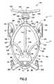
- FIG. 2is a top plan view of the stroller of FIG. 1 shown in its open position;
- FIG. 3is a front view of the stroller of FIG. 1 shown in its open position
- FIG. 4is a front view of the stroller of FIG. 1 with a covering of a hub removed therefrom;
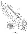
- FIG. 5is a left side view of the stroller of FIG. 1 shown in its open position
- FIG. 6is a right side view of the stroller of FIG. 1 shown in its open position
- FIG. 7is a side view of the stroller of FIG. 1 shown in its partially open position
- FIG. 8is a front view of the stroller of FIG. 1 shown in its partially open position
- FIG. 9is a side view of the stroller of FIG. 1 shown in its fully closed position
- FIG. 10is a front perspective view of the stroller of FIG. 1 shown in its fully closed position
- FIG. 11is a perspective view of a suspension module of the stroller of FIG. 1 ;
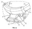
- FIG. 12is a portion of FIG. 1 illustrating a seat frame mounting member enlarged for magnification purposes
- FIG. 13is a perspective view of a seating portion of the stroller of FIG. 1 with a seat provided thereon;
- FIG. 14is a front schematic view illustrating a drive mechanism of the stroller of FIG. 1 ;
- FIG. 15is a top perspective view of a housing of the stroller of FIG. 1 illustrating a coupling mechanism
- FIG. 16is a side view of the housing of FIG. 15 ;
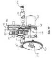
- FIG. 17is a top schematic view illustrating a motor and gear train of the drive mechanism of FIG. 14 ;
- FIGS. 18A and 18Bare side schematic views of a support structure of the stroller of FIG. 1 in an open position and a collapsed position, respectively;
- FIG. 19is a side schematic view of a lower arcuate support component of the support structure of the stroller of FIG. 1 ;
- FIG. 20is an enlarged view of the lower arcuate support component of the support structure of the stroller of FIG. 1 illustrating a latching mechanism
- FIG. 21is a side perspective view of the latching mechanism of FIG. 20 ;
- FIG. 22is an enlarged side perspective view illustrating the latching mechanism of FIG. 20 engaged between the lower arcuate support component and the upper arcuate support component of the support structure;
- FIGS. 23A-23Care side schematic views of a braking mechanism of the stroller of FIG. 1 in the released, partially engaged, and engaged positions, respectively;
- FIGS. 24 and 25are side schematic and exploded perspective views of a generator system of the stroller of FIG. 1 ;
- FIG. 26is a block diagram illustrating a control system for the generator system of FIGS. 24 and 25 ;
- FIG. 27is a block diagram of a power management system for use with the stroller of FIG. 1 ;
- FIG. 28is a top plan view of a handlebar assembly of the stroller of FIG. 1 .
- a strollerdenoted generally as reference numeral 1 , includes a hub 3 ; a support structure 5 having a first end 7 coupled to hub 3 and a second end 9 ; a seating portion 11 having a bottom portion 13 coupled to a top portion of hub 3 and a top portion 15 coupled to second end 9 of support structure 5 .
- Hub 3includes a housing 33 (see FIG. 4 ) that is covered by a covering 4 .
- Stroller 1is configured to collapse in the length, width, and height directions for storage and transportation as shown in FIGS. 9-10 and expand in the length, width, and height directions for use as shown in FIGS. 1-6 . An intermediate position between the collapsed position and the expanded position is shown in FIGS. 7-8 .
- Stroller 1further includes a first front leg 17 rotationally coupled to hub 3 and a second front leg 19 rotationally coupled to hub 3 .
- a first front wheel 21is rotationally coupled to and supported by first front leg 17 and a second front wheel 23 is rotationally coupled to and supported by second front leg 19 .
- a proximal end 25 , 27 of each front leg 17 , 19includes a post 29 , 31 that is rotatably engaged within housing 33 of hub 3 .
- Posts 29 , 31are mechanically coupled as will be discussed in greater detail hereinafter, thereby enabling rotational movement of each front leg 17 , 19 about housing 33 between an open position (see FIGS. 1-6 ) and a collapsed position (see FIGS. 9-10 ).
- each front leg 17 , 19pivotally connected to a distal end 35 , 37 of each front leg 17 , 19 is a pair of generally U-shaped wheel receiving members 39 , 41 for receiving respective front wheels 21 , 23 .
- Each wheel receiving member 39 , 41comprises an axle 43 to allow the front wheels 21 , 23 to roll about their respective axles 43 .
- Wheel receiving members 39 , 41are pivotally connected via a post 45 or any other suitable fastening mechanism to the distal ends 35 , 37 of front legs 17 , 19 to allow the front wheels 21 , 23 to pivot about respective axes substantially perpendicular to their axles 43 to accommodate changes in the rolling direction of the front of stroller 1 .
- a suspension module 47may be disposed between each wheel receiving member 39 , 41 and distal end 35 , 37 of each front leg 17 , 19 . While any of a number of suspension mechanisms well-known to those skilled in the art may be used, such as compression springs or the like, the preferred suspension module 47 also ensures the wheel receiving members 39 , 41 avoid being trapped or stuck when stroller 1 is automatically folded as described in greater detail hereinafter. To accomplish this, suspension module 47 is rotatably attached to an upper, front portion 49 of wheel receiving member 39 , 41 by a pin 51 . A torsion spring 53 is provided to bias suspension module 47 against wheel receiving member 39 , 41 during normal operation.
- Pin 51is placed in upper, front portion 49 of wheel receiving member 39 , 41 so that normal use of the stroller will not cause suspension module 47 to pull away from wheel receiving member 39 , 41 .
- front wheels 21 , 23could be oriented in an undesirable position whereby one or both of the front wheels 21 , 23 are wedged against another part of stroller 1 , blocking front legs 17 , 19 from folding properly.
- suspension module 47accommodates rotation about pin 51 of up to approximately 80 degrees in order to provide sufficient clearance for front legs 17 , 19 to fold properly.
- stroller 1further includes a first rear leg 55 and a second rear leg 57 .
- First rear leg 55 and second rear leg 57are rotationally coupled to hub 3 .
- first rear leg 55 and second rear leg 57are mechanically coupled to each other and to first front leg 17 and second front leg 19 as will be described in greater detail hereinafter.
- Each rear leg 55 , 57has a long cross-sectional dimension and a short cross-sectional dimension.
- each rear leg 55 , 57is configured to rotationally support a rear wheel 59 , 61 at a distal end 63 , 65 thereof within a respective rear wheel housing 67 , 69 .
- each rear wheel housing 67 , 69houses a braking mechanism, operated by either or both of brake pedals 75 , 77 for selectively locking rear wheels 59 , 61 to prevent inadvertent rolling movement of stroller 1 when the braking mechanism is locked.
- the braking mechanismwill be discussed in greater detail hereinafter with reference to FIGS. 23A-23C .
- each rear wheel housing 67 , 69also houses a power generating device operationally coupled to the respective axle 71 , 73 of rear wheels 59 , 61 .
- the power generating deviceis provided to recharge an onboard power supply, which provides power to an actuation device that allows the stroller to collapse and expand automatically.
- the power supplyalso provides power to additional accessories and onboard systems. The power generating device will be discussed in greater detail hereinafter with reference to FIGS. 24-27 .
- a proximal end 79 , 81 of each rear leg 55 , 57is rotationally coupled to hub 3 for enabling rotational movement of the rear legs 55 , 57 such that the rear legs 55 , 57 are movable between an open position (see FIGS. 1-6 ) and a collapsed position (see FIGS. 9-10 ).
- Rear legs 55 , 57in cross-section, have a long dimension and a short dimension.
- a plane bisecting the long dimension of a portion of rear legs 55 , 57 near distal ends 63 , 65 thereofis canted in the range of 12 to 25 degrees, preferably 19 degrees, in relation to a plane bisecting the long dimension of a portion of rear legs 55 , 57 near proximal ends 79 , 81 .
- This cantresults in a narrower footprint when rear legs 55 , 57 are in their collapsed position than when they are in their open position.
- the rear wheels 59 , 61move closer to each other to provide a more compact folded stroller 1 as illustrated in FIGS. 7-10 .
- seating portion 11includes a generally U-shaped lower seat frame assembly 83 and a generally U-shaped upper seat frame assembly 85 .
- Lower seat frame assembly 83 and upper seat frame assembly 85are coupled together giving seating portion 11 a generally elliptical-shaped appearance as shown in FIG. 1 .
- Lower seat frame assembly 83includes two lower arcuate seat frame components 87 , each having the same radius, pivotally connected at a first end 89 to a seat frame mounting member 91 to allow each of lower arcuate seat frame components 87 to pivot or rotate relative to seat frame mounting member 91 .
- seat frame mounting member 91is detachably and rotatably disposed on a mounting bracket 93 that is fixably attached to housing 33 of hub 3 .
- Mounting bracket 93has a mediate portion 95 rotatably attached at a front end 97 of mounting bracket 93 by a pin 99 .
- mediate portion 95is spring biased such that, when in use, the weight of an infant or child will cause seat frame mounting member 91 to push down on mediate portion 95 and, in turn, cause a bottom surface of mediate portion 95 to trigger a weight sensor (not shown).
- the weight sensor or other sensor designed to detect the presence of an infant or child in stroller 1is operatively connected to a control system to disable accidental actuation of the drive system that causes stroller 1 to collapse as will be more fully described hereinafter.
- upper seat frame assembly 85is comprised of two upper arcuate seat frame components 101 , each having the same arc radius.
- the arc radius of each of upper arcuate seat frame components 101may be the same as the arc radius of lower arcuate seat frame components 87 .
- This arc radiusmay be approximately 43 inches; however, this is not to be construed as limiting as the upper and lower arcuate seat frame components may have other arc radii.
- Upper arcuate seat frame components 101are pivotably connected at their first ends 103 to an upper seat frame mounting member 105 to allow each of the upper arcuate seat frame components 101 to pivot or rotate relative to the upper seat frame mounting member 105 .
- Each upper arcuate seat frame component 101is slidingly mated, at a second end 107 , to a second end 109 of its corresponding lower arcuate seat frame component 87 , such that upon collapsing stroller 1 , each lower arcuate seat frame component 87 will be slidingly received into its corresponding upper arcuate seat frame component 101 .
- each upper arcuate seat frame component 101may be slidingly received within its corresponding lower arcuate seat frame component 87 . As best seen by FIGS.
- this arrangement of lower arcuate seat frame components 87 and upper arcuate seat frame components 101allows the overall width of the generally U-shaped upper and lower arcuate seat frame assemblies 83 , 85 to decrease (consistent with the decrease in the lateral width of the wheels) as they move from their open position as shown in FIG. 3 to their collapsed position shown in FIG. 10 .
- stroller 1provides a seating portion 11 , a support structure 5 , a pair of front legs 17 , 19 , and a pair of rear legs 55 , 57 that define a linkage having a single degree of freedom, such that movement of any one of the seating portion 11 , the support structure 5 , the pair of front legs 17 , 19 , and the pair of rear legs 55 , 57 relative to one another toward their collapsed or open positions may cause movement of the others toward their collapsed or open positions.
- seating portion 11can be detached at lower seat frame mounting member 91 and upper seat frame mounting member 105 and replaced by either another seat or a different component.
- seating portion 11can be removed and replaced by a seating portion that can seat two children.
- a car seat or bassinet adaptercan be provided allowing a user to attach a car seat or a bassinet to stroller 1 .
- FIG. 7seating portion 11 is illustrated as being detached from stroller 1 .
- Seating portion 11includes a seat 111 removably disposed upon seating portion 11 .
- Seat 111is desirably manufactured from a soft cloth-like material such that seat 111 collapses when stroller 1 is collapsed and expands when stroller 1 is opened.
- Seat 111includes an upper seat portion 113 and a lower seat portion 115 .
- Upper seat portion 113securely sleeves around upper arcuate seat frame component 101 using snaps, zippers, or any other suitable fastening device for removably but securely fastening upper seat portion 113 to upper arcuate seat frame component 101 so that it is removable for cleaning or changing color, but is safely attached when in use.
- Upper seat portion 113extends along and wraps around upper arcuate seat frame component 101 from a lower end collar 117 on one side to a lower end collar 119 on the other side.
- Upper seat portion 113includes a seatback 121 , infant securing straps 123 , sunshade 125 secured to sunshade securing members 127 , a seat bottom 129 , and a pair of cupholders 131 integral to upper seat portion 113 .
- cupholders 131may be comprised of strips of padded fabric that are vertically stitched into the cupholder 131 to assist in maintaining its form. While not shown, an annulus can also be stitched into the top of cupholder 131 for better shape maintenance.
- Upper seat portion 113may further include reflective piping 133 to enable a user of stroller 1 to be seen during conditions of low or reduced visibility.
- lower seat portion 115extends from seat bottom 129 and is loosely sleeved around each lower arcuate seat frame component 87 with mesh or similar material in accordance with another aspect of the invention. Due to the fact that lower arcuate seat frame components 87 telescope into upper arcuate seat frame components 101 when stroller 1 is placed into the collapsed position, it is desirable for upper seat portion 113 to be connected to upper arcuate seat frame components 101 only because it does not need to collapse or fold vertically when the stroller is folded or collapsed. The lower seat portion 115 , on the other hand, must accommodate the telescoping of the lower arcuate seat frame components 87 and the concomitant loss of space.
- At least an edge area 135 of lower seat portion 115where it is attached to the lower arcuate seat frame components 87 , must be constructed with material that does not inhibit or bind the telescoping action.
- this materialis a fabric mesh.
- stroller 1may be provided with a cupholder tray device (not shown) having a base portion and a tray portion.
- the base portionis cylindrical and securely fits into either or both of cupholders 131 for a secure connection to upper seat portion 113 .
- the tray portionDisposed on the base portion, the tray portion extends flatly and in parallel with the ground to provide a multipurpose surface for the stroller occupant while still ensuring that there are no entrapment hazards, typically associated with fixed trays in the past.
- This cupholder tray devicemay be easily removed for cleaning or storage while the cupholders 131 are otherwise in use.
- At least one luggage wheel 137can be provided at a lower front portion of hub 3 of stroller 1 to facilitate transport of stroller 1 when it is in a collapsed position.
- support structure 5desirably has an arcuate shape and includes a lower arcuate support component 139 and an upper arcuate support component 141 .
- upper arcuate support component 141is slidingly mated with lower arcuate support component 139 such that upon collapsing stroller 1 , lower arcuate support component 139 slidingly sleeves on two sets of raised skis (not shown) into upper arcuate support component 141 .
- An upper arcuate support component end portion 143may have raised skis on an interior surface thereof that make contact with lower arcuate support component 139 .
- End portion 143 of upper arcuate support component 141is configured to be slidingly sleeved over an end portion 144 of lower arcuate support component 139 such that upon collapsing stroller 1 , upper arcuate support component 141 will slidingly sleeve down over lower arcuate support component 139 .
- arcuate support components 139 and 141are able to telescope or sleeve over or under each other because they have the same arc radius, but slightly different bore radii.
- a first end 7 of support structure 5is fixably attached to the housing 33 disposed within hub 3 .
- Stroller 1may be provided with a removeable storage bag (not shown).
- the storage bagis configured to be hanged from hooks or other fastening devices protruding from upper arcuate support component 141 at a point inside a line drawn between the center of each of rear wheels 59 , 61 .
- hooksbeing placed in front of rear wheels 59 , 61 , a large amount of weight, whether from shopping bags or a fully loaded storage bag, will not cause an unsafe tipping condition as is seen in many current strollers.
- arcuate support assembly 5has the additional advantage of supporting seating portion 11 and a handlebar assembly 145 with a single tube while providing significant clearance in the seat area of seating portion 11 to enable placement of a carry cot (not shown) or provide for a recline of the seat 111 without hitting arcuate support assembly 5 .
- Handlebar assembly 145includes a central component 147 , a first handle 149 coupled to central component 147 , and a second handle 151 coupled to central component 147 .
- First handle 149 and second handle 151allow a user to maneuver stroller 1 .
- first handle 149 and second handle 151are configured to move from a first, retracted position, as shown in FIG. 2 , to a collapsed position by pushing buttons 153 and rotating each handle 149 , 151 around central component 147 .
- Central component 147 of handlebar assembly 145is coupled to second end 9 of support structure 5 by a telescoping member 155 .
- Telescoping member 155extends vertically from second end 9 of support structure 5 , thereby allowing a user to adjust handlebar assembly 145 for height in the directions of arrow B 1 shown in FIG. 5 .
- Handlebar assembly 145may further include a controller interface 157 having a display portion 158 for actuating the powered aspects of stroller 1 of the present invention and for providing various other information as will be discussed in greater detail hereinafter.
- a storage compartment 159may also be positioned at second end 9 of support structure 5 .
- housing 33 of hub 3has a generally trapezoidal shape having a top surface 161 and two side surfaces 163 extending from top surface 161 at an angle.
- Housing 33is preferably comprised of steel or another suitable material and provides a sturdy foundation for stroller 1 .
- some of elements of FIGS. 14-18have been omitted so that other items may be viewed.
- a left coupling system 171 for the left rear leg 57 and left front leg 19includes a rear leg mounting bar 173 to which rear leg 57 is fixedly coupled; a gear 175 mounted on side surface 163 of housing 33 ; a bushing 177 coupled to gear 175 and extending through a slot 179 provided at an end of mounting bar 173 ; a J-shaped spool component 181 fixedly coupled to mounting bar 173 between slot 179 and rear leg 57 ; and a cable 183 configured to wrap around J-shaped spool component 181 and post 31 of front leg 19 .
- An identical right coupling systemis mounted on the other side surface 163 for mechanically coupling right rear leg 55 and right front leg 17 .
- Housing 33further includes a drive mechanism 165 mounted thereon which powers stroller 1 to be moved back and forth between its open and collapsed positions. More specifically, drive mechanism 165 is configured to mechanically link and simultaneously drive gears 175 of right and left coupling systems 171 , thereby causing legs 17 , 19 , 55 , 57 to synchronously expand or collapse. Drive mechanism 165 is further configured to cause the support structure 5 to expand or collapse as will be discussed in greater detail hereinafter.
- drive mechanism 165includes a motor 167 mounted in a fixed position on an inner casing 169 of housing 33 , and a gear train 170 positioned within inner casing 169 and having a first gear driven by a drive shaft of motor 167 (see FIG. 17 ).
- Gear train 170is configured to allow a single motor (i.e., motor 167 ) to drive rotational drive spool gear 185 and first and second drive gears 187 , 189 as will be discussed hereinafter.
- Motor 167may be of a reversible type, or alternatively, a single-direction motor with mechanical reversing means.
- gear train 170is configured to allow motor 167 to drive first and second drive gears 187 , 189 through first and second universal joints 191 , 193 .
- First and second universal joints 191 , 193are configured to operationally couple first and second drive gears 187 , 189 and gear train 170 and allow first and second drive gears 187 , 189 to extend through and be positioned adjacent to angled side surfaces 163 of housing 33 as shown in FIG. 15 . Accordingly, motor 167 , through gear train 170 and first and second universal joints 191 , 193 , is capable of simultaneously driving first and second drive gears 187 , 189 .
- first rear leg 55 and second rear leg 57are mechanically coupled between gear train 170 and first and second universal joints 191 , 193 .
- First and second drive gears 187 , 189are positioned to rotationally drive gears 175 of right and left coupling systems 171 .
- stroller 1is in an expanded position as shown in FIG. 18A .
- bushing 177is aligned within slot 179 with an axle of gear 175 along axis Y 1 .
- Axis Y 1is perpendicular to an axis X 1 along which rear leg 57 extends. This configuration locks rear legs 55 , 57 in the open position even if a user provides a downward force on legs 55 , 57 .
- motor 167drives gear train 170 which in turn drives universal joints 191 , 193 , causing drive gears 187 , 189 to rotate.
- This rotationdrives gears 175 , causing bushings 177 to travel within slots 179 in rear leg mounting bar 173 .
- posts 29 , 31 for supporting front legs 17 , 19are each mechanically coupled to respective rear legs 55 , 57 by cable 183 connected to spool component 181 , as rear legs 55 , 57 rotate in the direction of arrow A 1 , front legs 17 , 19 also rotate in the direction of arrow A 2 to the collapsed position.
- bushing 177is aligned within slot 179 with an axle of gear 175 along axis Y 2 .
- Axis Y 2is perpendicular to an axis X 2 along which rear leg 57 extends. This configuration locks rear legs 55 , 57 in the collapsed position even if a user provides an upward force on rear legs 55 , 57 .
- drive mechanism 165can be controlled to cause stroller 1 to return to the open position of FIG. 18A .
- motor 167drives gear train 170 , which in turn drives universal joints 191 , 193 , causing drive gears 187 , 189 to rotate.
- This rotationdrives gears 175 , causing bushings 177 to travel within slots 179 in rear leg mounting bar 173 .
- Thiscauses rear leg mounting bar 173 , and thereby rear legs 55 and 57 , to rotate in the direction of arrow A 3 to the open position.
- posts 29 , 31 for supporting front legs 17 , 19are each mechanically coupled to respective rear legs 55 , 57 by cable 183 connected to spool component 181 , as rear legs 55 , 57 rotate in the direction of arrow A 3 , front legs 17 , 19 also rotate in the direction of arrow A 4 to the open position.
- This rotation of front legs 17 , 19may be aided by the placement of a spring 195 around posts 29 , 31 that support front legs 17 , 19 .
- the use of such springs 195allows a smaller, less powerful motor to be used in drive mechanism 165 .
- drive mechanism 165further includes a spool gear 185 provided in gear train 170 and configured to be driven by motor 167 .
- Spool gear 185is fixedly attached to and configured to drive a spool shaft 197 .
- Spool shaft 197further includes a spool pair 199 having a first side 199 a and a second side 199 b fixedly attached thereto.
- a first cable(not shown) is run from a first side 199 a of spool pair 199 up to and around a first key pulley 201 mounted inside end portion 144 of lower arcuate support component 139 .
- the cableruns around first key pulley 201 and through a first pulley 203 of a latching mechanism 205 .
- a second cable(not shown) is run from a second side 199 b of spool pair 199 up to and around a second key pulley 207 mounted inside end portion 144 of lower arcuate support component 139 .
- the cableruns around second key pulley 207 and through a second pulley 209 of latching mechanism 205 .
- Latching mechanism 205includes a pair of latch members 211 configured to extend through a recess 213 in upper arcuate support component 141 . Since upper arcuate support component 141 is designed to slide over lower arcuate support component 139 as previously described, activation of spool pair 199 in either direction moves support structure 5 between an open and a collapsed position. Moreover, due to the fact that the seating portion 11 can also telescope as previously described, activation of the spool pair 199 also moves seating portion 11 between an open and a collapsed position.
- latching mechanism 205When in a fully-open position, support structure 5 comprises latching mechanism 205 that ensures the stroller 1 remains open when in the open position.
- latching mechanism 205includes a pair of latch members 211 biased to extend outwardly from support structure 5 .
- Latch members 211are movable to a retracted position not extending outwardly from support structure 5 .
- Recesses 213 for receiving latch members 211 when it is in its extended positionare provided in upper arcuate support component 141 to receive and engage latch members 211 therein, and thereby engage lower arcuate support component 139 as shown in FIG. 22 . Due to the single degree of freedom of the stroller linkage, this prevents the stroller from being moved toward its collapsed or folded position.
- the latch members 211can be released from recesses 213 by moving the latch to its retracted position to disengage the latch members 211 and thereby disengage upper arcuate support component 141 to allow telescoping or sleeving movement of upper arcuate support component 141 over lower arcuate support component 139 and accordingly allow movement of the stroller toward its collapsed position.
- latch members 211After latch members 211 have been disengaged and the stroller has been moved to its collapsed position, and upon movement of the stroller toward its open position, latch members 211 are biased against the interior surface of upper arcuate support component 141 until the stroller is fully open, at which point latch members 211 are aligned with, and extend into, recesses 213 to prevent movement of the stroller toward its collapsed position until the latch members 211 are retracted.
- motor 167causes gear train 170 to rotationally drive spool gear 185 and, correspondingly, the spool pair 199 whereby the cable (not shown) is simultaneously wound and unwound on the spool pair 199 and upper arcuate support component 141 is driven longitudinally along lower arcuate support component 139 between a collapsed and an open position.
- the seating portion 11is also moved between a collapsed and an open position.
- drive mechanism 165is operatively engaged with support structure 5 and seating portion 11 to move them between their collapsed and open positions.
- stroller 1was described hereinabove as including drive mechanism 165 , this is not to be construed as limiting as other drive mechanisms may be utilized.
- U.S. Provisional Patent Application No. 61/094,574entitled “Stroller”, discloses an alternative drive mechanism. This application claims priority to U.S. Provisional Patent Application No. 61/094,574 and it is hereby incorporated by reference.
- drive mechanism 165includes an electric motor 167 capable of moving the elements of stroller 1 .
- the drive mechanismmay utilize a variety of other elements.
- the drive mechanismmay be a hydraulic or pneumatic drive, with hydraulic or pneumatic tubes extending from a hydraulic or pneumatic pump, internally and/or externally of one or more stroller components, to desired locations of the stroller to effect movement of one or more stroller components. Cables, running internally and/or externally of one or more stroller components, may be utilized.
- Suitable accommodation for the cables, pneumatic tubing, hydraulic tubing, and/or electrical wiresis preferably provided to prevent pinching, folding, or other deformation, which would prevent suitable or optimal operation of these elements.
- An energy storing drive or drive mechanism(such as one utilizing a spring loaded element, other resilient element, or electromagnetic storage element), which stores energy when one or more stroller components are moved from one position to another for subsequent release of part or all of the stored energy to effect movement of the same or other stroller components, may be utilized.
- Rotary drives and/or drive mechanisms, or non-rotary drives and/or drive mechanismsmay be utilized.
- One type of drive or drive mechanismmay be utilized, or any combination of two or more drive mechanisms may be utilized either in combination with one another or individually.
- the drive mechanismmay be located at, or in proximity with, a location (or locations) on stroller 1 at which one or more stroller components are desired to be moved, or the drive mechanism(s) may be located remote from such location or locations, with suitable operative engagement extending between a remotely located drive mechanism and the location or locations on the stroller at which one or more stroller components are desired to be moved.
- operative engagementmay include, for instance, cables, hydraulic tubes, pneumatic tubes, electromagnetic forces, electric wires, or any of a wide variety of other engagements.
- stroller 1may be provided with additional latch or locking components operatively connected with drive mechanism 165 , or a separate drive mechanism, which latches are moveable between a locking position which maintains the stroller in its collapsed position, and an unlocked position which allows the stroller to move from its collapsed position to its open position.
- a braking system 215 for stroller 1is provided in first rear wheel housing 67 and second rear wheel housing 69 and operatively controlled by brake pedals 75 , 77 .
- the breaking systems 215 provided in each rear wheel housing 67 , 69are identical and accordingly only one braking system will be described hereinafter.
- Braking system 215includes a brake pedal 75 positioned such that it extends from rear wheel housing 69 and a braking cam 217 operationally coupled to brake pedal 75 and rotatable around a pivot point 219 from a first position (see FIG. 23A ) to a second position (see FIG. 23C ). More specifically, brake pedal 75 includes a peg 221 that is positioned within a slot 223 in the braking cam 217 . As brake pedal 75 is depressed, peg 221 travels from a first end of slot 223 to a second end of slot 223 , thereby causing braking cam 217 to rotate about pivot point 219 . Braking cam 217 has a modified elliptical shape as shown in FIGS. 23A-23C .
- Braking system 215further includes a brake lever 225 having a first end 227 configured to contact braking cam 217 when braking cam 217 is in the second position, and a second end 229 having a plurality of teeth 231 configured to engage the teeth 232 of a gear 233 driven by first rear wheel 59 of stroller 1 when braking cam 217 is in the second position, thereby preventing rotation of first rear wheel 59 and movement of stroller 1 .
- a first depression of brake pedal 75causes braking cam 217 to rotate around pivot point 219 from the first position to the second position, thereby causing the teeth 231 of brake lever 225 to engage gear 233 to prevent rotation of first rear wheel 59 .
- a second depression of brake pedal 75causes braking cam 217 to rotate around the pivot point from the second position to the first position, thereby causing the teeth of the brake lever to disengage the at least one gear to allow rotation of the first wheel.
- second rear wheel 61includes a braking device positioned within second rear wheel housing 69 that is identical to braking system 215 and operationally coupled to brake pedal 75 via a cable (not shown) or any other suitable coupling device such that the depression of brake pedal 75 causes the actuation of the braking system provided in second rear wheel housing 69 , thereby preventing rotation of second rear wheel 61 .
- a second depression of brake pedal 75releases the braking device provided in second rear wheel housing 69 , thereby allowing rotation of second rear wheel 61 .
- stroller 1is desirably configured to recharge or maintain a predetermined power level of its onboard power source through a dual generator system which is driven by the turning of the stroller wheels.
- the dual generator systemincludes identical generator systems 235 positioned in each of the rear wheel housings 67 , 69 . Since these generator systems are identical, only one of these generator systems 235 will be described hereinafter.
- Generator system 235includes a gear reduction system 237 operationally coupled between axle 73 of second rear wheel 61 and a generator 239 .
- Gear reduction system 237includes a plurality of gears, such as gear 233 which is driven by axle 73 as second rear wheel 61 rolls, second gear 241 driven by gear 233 , third gear 243 driven by second gear 241 , and fourth gear 245 driven by third gear 243 .
- Fourth gear 245is coupled to a drive shaft of generator 239 such that rotation of fourth gear 245 causes generator 239 to produce electricity.
- a rubber bushing 247may be provided to surround all or part of generator 239 for noise reduction.
- Generator 239may be embodied as an electric motor.
- Gear reduction system 237is required because coupling a rear wheel 59 , 61 directly to the motor used as generator 239 to recharge a battery is impractical since it would require a large velocity on the wheel in order to achieve the roughly 3,000 revolutions per minute or 50 revolutions per second for which such motors are typically optimized. In order to accomplish the desired recharging with the wheel and a motor, gear reduction system 237 is required.
- Control system 249includes a transistor 251 , such as a MOSFET, provided between generator 239 and a power storage device 253 .
- a microcontroller 255is provided to control the state of transistor 251 .
- transistor 251is turned on or off by microcontroller 255 such that transistor 251 either allows current to flow into and charge power storage device 253 or it blocks it from doing so. If no current is allowed to flow, generator 239 is not generating power and it is easy to turn (or push the stroller) regardless of the speed. Accordingly, microcontroller 255 pulses transistor 251 with a duty cycle with a certain proportion of “on” time. The greater that proportion, the more current is allowed to flow from generator 239 to power storage device 253 . This “on” time is lowered in proportion as the user pushes the stroller faster to prevent them from feeling that there is too much resistance.
- microcontroller 255is programmed to charge a smaller percentage of each duty cycle, and thus make stroller 1 easier to push, when the stroller is first moved from a standstill into motion. It is also within the scope of the present invention to program microcontroller 255 to modify the duty cycle to maximize recharging activity when the stroller is being pushed downhill, which can be monitored through the use of a MEMS gyroscope, a mercury switch, or other such device. This aspect has the added benefit of slowing the stroller on downgrades for safety. This is called regenerative braking.
- Power storage device 253 of the present inventionis desirably a nickel metal hydride rechargeable battery and is positioned within housing 33 .
- microcontroller 255also controls the distribution of power generated by generator 239 and stored in power storage device 253 to a plurality of subsystems, such as drive mechanism 165 , a lighting system 257 , and any of a plurality of accessories 259 , such as speakers, a cell phone charging device, and a portable music player.
- a plurality of subsystemssuch as drive mechanism 165 , a lighting system 257 , and any of a plurality of accessories 259 , such as speakers, a cell phone charging device, and a portable music player.
- Stroller 1includes lighting system 257 to enhance safety.
- Lighting system 257includes two lighting subsystems that provide: a) constant lighting for safety purposes such that the stroller can always be seen; and b) pathway lighting so that irregularities in the path of travel of stroller 1 can be seen.
- the constant lighting subsystemincludes a daytime running light 303 positioned on first front leg 17 and a daytime running light 303 positioned on second front leg 19 .
- the daytime running lights 303are positioned on front legs 17 , 19 such that the light produced thereby is visible from 360 degrees around stroller 1 .
- the pathway lighting subsystemincludes a pair of path lights 305 located underneath hub 3 and positioned to point forward. Accordingly, the path lights 305 cast light and illuminate surface irregularity in a path in front of stroller 1 . Desirably, path lights 305 are located on hub 3 at a position that is within about 10 inches of pathway.
- Lighting system 257is powered by power storage device 253 which is charged by generator 239 .
- Microcontroller 255is operatively coupled to the constant lighting subsystem and pathway lighting subsystem and is configured to control the status of these subsystems. For instance, microcontroller 255 is configured to turn daytime running lights 303 on when the stroller is placed in the open position and off when the stroller is in the collapsed position. In addition, microcontroller 255 is configured to turn on path lights 305 in low light conditions so that the user can clearly see any irregularities in the pathway. The microcontroller 255 turns path lights 305 on based on either manual feedback from a user or automatic feedback from an ambient light detecting sensor (not shown) provided on stroller 1 .
- Controller interface 157may include an on/off switch for path lights 305 that a user can actuate.
- display 158 provided on controller interface 157may provide a message to the user regarding the status of both daytime running lights 303 and path lights 305 .
- Path lights 305 and daytime running lights 303may be embodied as light emitting diodes (LEDs).
- the power source for driving motor 167may be a replaceable and/or rechargeable battery or batteries, conventional battery or batteries, and/or a direct electrical supply such as that available from an electrical outlet.
- the power sourcemay be permanently attached to the stroller, or may be removable for charging, replacement, or the like.
- a relatively small power sourcemay be utilized which has sufficient power to move the stroller back and forth between its open and collapsed positions, but which does not have sufficient additional power to regularly or routinely power additional accessories or onboard systems without draining its power undesirably quickly.
- a larger power sourcemay be utilized which not only has sufficient power to move the stroller back and forth between its open and collapsed conditions, but also has additional capacity to drive one or more additional accessories and/or onboard systems, which accessories and/or onboard systems may be integral with the stroller or may be modular additions or connections to the stroller.
- a control switch 261is provided, preferably in the controller interface 157 , which may be an integral portion of handlebar assembly 145 or detachable therefrom, for causing actuation of drive mechanism 165 .
- Control switch 261is operatively connected to motor 167 through microcontroller 255 to control actuation of motor 167 , which in turn controls drive mechanism 165 , which in turn controls movement of the front legs 17 , 19 , rear legs 55 , 57 , and support structure 5 between their collapsed and open positions as discussed in detail hereinabove.
- the wires extending between the control switch 261 , microcontroller 255 , and motor 167are all disposed internally of the stroller elements, such as extending internally within hollow tubular members.
- the control switch 261or a separate control switch and/or a common controller, may also be operatively coupled to one or more latch mechanisms to move the latch mechanisms from their latched positions in which they prevent the stroller from moving from its fully-open position toward its collapsed position, to their unlatched positions in which they allow the stroller to move from its fully-open position towards its collapsed position.
- Motor 167or a separate drive mechanism, may be operatively connected to a control switch and/or controller to affect automatic movement of the latches upon actuation by control switch 261 .
- the unlatching of the one or more latchesis preferably carried out prior to, or simultaneous with, the initiation actuation of motor 167 .
- a control switchmay be provided at, or in proximity with, one or more latches on the stroller (or operatively engaged with one or more latches), such that upon, or subsequent to, manually unlatching the one or more latches, the actuator is actuated to effect automatic movement of the desired one or more stroller components from a first position to a second position.
- a control switchsuch as a position sensing switch (which may be an optical switch, electrical contact switch, or any other type of switch) may be provided which is operatively engaged with a controller which controls the actuation of the drive mechanism as desired (which may be in any of a wide variety of rates, sequences, options, etc.)
- the control switch or switchesmay be located and configured to be triggered or actuated during conventional manual unlatching of the latch or latches, or may be at a convenient location on the stroller which allows the control switch to be easily actuated while, or immediately subsequent to, unlatching of the latch or latches. It may be desirable to provide an arrangement in which two or more control switches associated with respective latches are required to both be actuated to effect automatic movement of the desired one or more stroller components from a first position to a second position.
- controller interface 157 used to control motor 167 to control the collapsing and opening movements, or other desired stroller component movements, of stroller 1may be constructed and configured to have two or more discrete switches (such as control switch 261 and control switch 263 ) which need to be actuated simultaneously, or in a predetermined sequence or pattern, to effect actuation of motor 167 and thereby the movable components of the stroller, so as to prevent inadvertent movement of the stroller components, such as inadvertent movement of a stroller toward its deployed and/or collapsed positions.
- the two or more discrete switches 261 , 263are preferably spaced sufficiently apart from one another, or otherwise disposed relative to one another, so as to prevent inadvertent actuation of one switch upon actuation of the other switch.
- a first control switch 263is pushed, causing a timer 265 to count up to “three” whereupon a second control switch 261 is pushed by the user in order to actuate the stroller 1 folding or unfolding action.
- the control switch or switchesmay be constructed to require that one switch, or a combination of switches, be engaged throughout the movement of the desired stroller components, such as during opening and/or folding operations of strollers designed for automatic opening and closing.
- a suitable control switch or switches, and/or suitable controllermay be provided such that only one actuation of a switch or switches is required to effect the desired movement of two or more stroller components, such as full movement of a stroller between its fully-deployed or open and/or fully-collapsed or folded positions.
- a controllermay be provided to move the stroller to a position intermediate its fully-open and/or fully-collapsed position, such as a midway condition as shown in FIGS. 7 and 8 , with one actuation of a switch or switches, and further or complete movement of the stroller to its fully-deployed and/or fully-collapsed positions requiring a subsequent actuation of a switch or switches.
- Microcontroller 255is desirably programmed to automatically switch directions with each successive actuation. For example, should the movement of the stroller toward the fully-collapsed position be stopped at an intermediate point, such as upon a user noticing a toy in the stroller which is to be removed, but which has been enclosed by the partially-collapsed stroller, the user need only release the switch or switches and reengage them for movement in the opposite direction, toward the fully-open position. The motor may then be stopped and re-actuated for movement of the stroller to its fully-collapsed position.
- the control switch and/or controllermay be mounted on the frame of the stroller, such as on the rear wheel support member or elsewhere on the stroller, or alternatively, the control switch and/or controller may be separate from the stroller, such as on a key fob or other portable device, and operated using wireless technology. This may facilitate the ability of a user to hold a child or baby with both hands throughout the opening and/or collapsing of the stroller.
- the controllermay be configured and constructed utilizing any of a wide variety of known controller designs and/or mechanisms.
- the controllermay utilize electrical contact switches and/or may utilize a processor, microprocessor, or microcontroller.
- the controllermay operate in conjunction with one or more sensors, such that upon actuation, or lack of actuation, of one or more sensors the motor does not operate even when the one or more switches, or other control actuation mechanism, which would normally actuate the motor, are properly actuated.
- the controllermay also be provided with switches or other actuators for controlling additional items such as a timer, an alarm clock feature, a music device, a monitor, a speedometer, a pedometer, or any other desirable items.
- a general auxiliary device connector 267may be provided through which various auxiliary devices may be interchangeably connected and controlled by the controller and/or suitable control switch, which devices may be powered by the power source for the stroller, or through an independent power source.
- auxiliary device connector 267may include a first port 269 for connecting speakers or a portable audio player, and a second port 271 for connecting a cell phone or other portable electronic device for recharging.
- Controller interface 157also includes display 158 mounted onboard stroller 1 to provide any of a wide variety of visual or audio feedback or ambient conditions to the user such as a battery level indicator 273 , a temperature reading 275 , an odometer 277 , speedometer 279 , clock (not shown), recharging indicator 281 , the position of the stroller frame, whether the stroller will move toward its open or collapsed condition when next actuated, the presence of a baby or child in the stroller 283 , instructions for use and operation of the stroller, emergency telephone numbers, environmental conditions, distance walked, average speed, or any other desired feature or parameter.
- Odometer 277may be a permanent odometer providing a reading of the total distance traveled during the lifetime of stroller 1 .
- controller interface 157 and display 158may be provided remotely, such as on a key fob.
- Stroller 1may also include one or more object sensors having the ability to detect the presence of objects within the interior portion of the stroller and to interrupt and/or prevent movement of the stroller in the direction toward its collapsed condition when the object sensor detects the presence of an object within the interior portion of the stroller.
- the object sensor or sensorsmay be of any known type, or any type later developed, such as a mechanical weight sensor, a proximity sensor, a motion sensor, a light beam sensor, or any other device having the ability to detect the presence of an object within the interior of the stroller.
- the sensor or sensorsmay be electronic and may send a signal that is electrically acted upon to prevent or interrupt power to the motor, and/or the sensors may be mechanical and actuate a physical lock or a brake to prevent further collapsing or the full collapsing movement of the stroller. Sensors may also be used to detect the presence of modular add-on devices connected to the stroller, such that movement of the stroller to its collapsed condition is prevented when a connected add-on is detected, thereby preventing potential damage to the add-on device.
- Stroller 1may also include position sensors utilized at selective locations on the frame to send a signal indicative of the positions of one or more components or elements of the stroller.
- the position sensorscan be used for several purposes, such as sending a signal to the display to provide a visual and/or audio indication to the user as to the current position or of the deployment or the collapsing of the stroller and/or to provide an interrupting signal (or non-signal) if a position sensor or sensors are not engaged as they would be during proper deployment and/or collapsing of the stroller.
- any one or more of several known types of sensorsmay be utilized, such as rotary encoders at any one or more frame component pivot points, and/or limit or contact switches which are engaged as selective elements of the stroller move to their proper positions, or improper positions, during deployment and/or collapsing of the stroller.
- position sensorsmay be mounted to the stroller at positions which provide indication that the stroller has moved to its fully-deployed condition, its fully-collapsed condition, or any condition in-between; and/or position sensors may be mounted at locations to detect the engagement or lack of engagement of latches.
- Position sensorsmay operate in conjunction with electronic timer controls such that a signal to effect stoppage of power to the motor is sent if the position sensor is not engaged within a predetermined time period.
- a resistance sensing device and/or timermay be operatively connected to the controller to stop movement and/or move toward the unfolded or open position when folding is interrupted, e.g. when too much resistance toward folding movement is encountered or when the fully-closed position is not achieved within a predetermined time.
- a clutchmay be provided between the motor and the elements to which it is connected to provide slippage of the driving force of the motor if too much resistance is encountered.
- a manual overridemay also be provided to allow manual movement of the stroller between its open and closed positions and/or manual movement of any stroller components between their first and second positions, which would normally be carried out automatically by a drive mechanism.
- Such manual overridemay be desirable for any of a number of reasons, such as the power source being too low to effect the desired automatic movement or the failure of any parts.
- a clutch or clutchesmay be provided between one or more drive mechanism elements and their associated stroller components for use as a manual override, whereby the clutch may be moved to a position in which it effects disengagement of the drive mechanism.
- a mechanical lever or rotary elementmay be provided at any point in the drive mechanism and/or between the drive mechanism and one or more stroller components associated with the drive mechanism, which is movable between an automatic position (in which a drive mechanism is operatively engaged with one or more stroller components to move the one or more stroller components automatically) and a manual position (in which a drive mechanism is disengaged from its operative engagement with one or more stroller components).
- the movement or movements of the inventive strollers of the present inventioncan be carried out in a wide variety of ways, such as telescoping of components, sliding of components, pivoting of components, rectilinear movement of components, cam driven or guided movement of components, or any other known linkage which allows movement of two or more components relative to one another.
- any stroller constructionwhich has one or more front wheels and one or more rear wheels, or having any other wheel configuration such as a circular arrangement of the wheels, left and right wheels, or any other arrangement, in which the stroller has some type of drive for moving at least one of the wheels from a first position to a second position may be constructed.
- virtually any stroller constructioncan be utilized which allows automatic movement of at least one of its wheels from an open position to a collapsed position, or back and forth between collapsed and open positions, or between an extended position and a retracted position.
- a strollermay be provided having a frame with one or more components, which may be wheel components and/or other stroller components or attachments (or components to which attachments may be connected) with a drive operatively connected with the one or more components to move them from a first position to a second position. This may be used for automatic movement of the components between any desired first and second positions.
- one or more stroller components or attachmentsmay be moved between three or more selective positions by the drive mechanism and/or control switches, and/or one or more controllers.
- Backup mechanical systemsmay be provided to serve as the drive for moving the wheels and/or other stroller components.
- a mechanical system(s)may use elements common with the automatic system(s), use independent element(s), or both.
- Stroller 1may also be provided such that front and/or rear wheels move front to back and/or back to front and/or side to side and/or top to bottom and/or bottom to top. This may apply to other stroller components as well.
- a strollermay be provided in which the wheels of the stroller remain on the ground or otherwise relatively stationary, while other stroller components move forwardly and/or rearwardly and/or sideways and/or upwardly and/or downwardly between collapsed and open positions.
- stroller embodiments described in detail aboveare simple, robust, and extremely easy to use.
- the various structures of stroller 1may all be made of any suitable plastics, formed of metals, or constructed from any other suitable material.
Landscapes
- Engineering & Computer Science (AREA)
- Chemical & Material Sciences (AREA)
- Combustion & Propulsion (AREA)
- Transportation (AREA)
- Mechanical Engineering (AREA)
- Health & Medical Sciences (AREA)
- Public Health (AREA)
- Carriages For Children, Sleds, And Other Hand-Operated Vehicles (AREA)
- Handcart (AREA)
Abstract
Description
Claims (17)
Priority Applications (2)
| Application Number | Priority Date | Filing Date | Title |
|---|---|---|---|
| US12/554,479US8500152B2 (en) | 2007-02-19 | 2009-09-04 | Collapsible stroller |
| US13/934,604US8733785B2 (en) | 2008-09-05 | 2013-07-03 | Collapsible stroller |
Applications Claiming Priority (13)
| Application Number | Priority Date | Filing Date | Title |
|---|---|---|---|
| US89062407P | 2007-02-19 | 2007-02-19 | |
| US89060707P | 2007-02-19 | 2007-02-19 | |
| US89061307P | 2007-02-19 | 2007-02-19 | |
| US89060507P | 2007-02-19 | 2007-02-19 | |
| US89061807P | 2007-02-19 | 2007-02-19 | |
| US89061607P | 2007-02-19 | 2007-02-19 | |
| US89060807P | 2007-02-19 | 2007-02-19 | |
| US89061907P | 2007-02-19 | 2007-02-19 | |
| US89060107P | 2007-02-19 | 2007-02-19 | |
| US89059707P | 2007-02-19 | 2007-02-19 | |
| US12/032,370US20080211206A1 (en) | 2007-02-19 | 2008-02-15 | Stroller |
| US9457408P | 2008-09-05 | 2008-09-05 | |
| US12/554,479US8500152B2 (en) | 2007-02-19 | 2009-09-04 | Collapsible stroller |
Related Parent Applications (1)
| Application Number | Title | Priority Date | Filing Date |
|---|---|---|---|
| US12/032,370Continuation-In-PartUS20080211206A1 (en) | 2007-02-19 | 2008-02-15 | Stroller |
Related Child Applications (1)
| Application Number | Title | Priority Date | Filing Date |
|---|---|---|---|
| US13/934,604ContinuationUS8733785B2 (en) | 2008-09-05 | 2013-07-03 | Collapsible stroller |
Publications (2)
| Publication Number | Publication Date |
|---|---|
| US20100045001A1 US20100045001A1 (en) | 2010-02-25 |
| US8500152B2true US8500152B2 (en) | 2013-08-06 |
Family
ID=41797503
Family Applications (5)
| Application Number | Title | Priority Date | Filing Date |
|---|---|---|---|
| US12/554,479Active2029-09-12US8500152B2 (en) | 2007-02-19 | 2009-09-04 | Collapsible stroller |
| US12/554,582Active2029-01-03US8193650B2 (en) | 2007-02-19 | 2009-09-04 | Power generation system for a stroller |
| US12/554,561Active2029-04-04US8215808B2 (en) | 2007-02-19 | 2009-09-04 | Lighting system for a stroller |
| US12/554,529Active2029-06-05US8499898B2 (en) | 2007-02-19 | 2009-09-04 | Braking system for a stroller |
| US13/934,604Expired - Fee RelatedUS8733785B2 (en) | 2008-09-05 | 2013-07-03 | Collapsible stroller |
Family Applications After (4)
| Application Number | Title | Priority Date | Filing Date |
|---|---|---|---|
| US12/554,582Active2029-01-03US8193650B2 (en) | 2007-02-19 | 2009-09-04 | Power generation system for a stroller |
| US12/554,561Active2029-04-04US8215808B2 (en) | 2007-02-19 | 2009-09-04 | Lighting system for a stroller |
| US12/554,529Active2029-06-05US8499898B2 (en) | 2007-02-19 | 2009-09-04 | Braking system for a stroller |
| US13/934,604Expired - Fee RelatedUS8733785B2 (en) | 2008-09-05 | 2013-07-03 | Collapsible stroller |
Country Status (7)
| Country | Link |
|---|---|
| US (5) | US8500152B2 (en) |
| EP (1) | EP2323889A4 (en) |
| CN (1) | CN102202955B (en) |
| AU (1) | AU2009289601B2 (en) |
| BR (1) | BRPI0913501A2 (en) |
| CA (1) | CA2736129C (en) |
| WO (1) | WO2010028235A1 (en) |
Cited By (3)
| Publication number | Priority date | Publication date | Assignee | Title |
|---|---|---|---|---|
| US20150197267A1 (en)* | 2014-01-13 | 2015-07-16 | Jane, S.A. | Suspension for baby pushchairs |
| WO2018031553A1 (en) | 2016-08-10 | 2018-02-15 | Diono, Llc | Collapsible stroller with trigger handle |
| US11447168B1 (en)* | 2021-07-02 | 2022-09-20 | Ferrergari LLC. | Motorized stroller having a platform and ergonomic means |
Families Citing this family (73)
| Publication number | Priority date | Publication date | Assignee | Title |
|---|---|---|---|---|
| ITDP20070027A1 (en)* | 2007-12-17 | 2009-06-18 | Aniello Scialli | ASSEMBLY OF TECHNOLOGIES FOR RENEWABLE ENERGY |
| GB0816512D0 (en)* | 2008-09-10 | 2008-10-15 | Cassidy Clare E | Electronic media players and speakers for use with infant carrier |
| US8356824B1 (en)* | 2010-03-25 | 2013-01-22 | Manweiler Randal J | Stroller illumination system |
| US8602904B2 (en)* | 2010-05-10 | 2013-12-10 | Wonderland Nurserygoods Company Limited | Swing apparatus and control system and method therefor |
| GB2480278A (en)* | 2010-05-11 | 2011-11-16 | Jelly Products Ltd | A collapsible support frame for carrying a load |
| GB2480279A (en)* | 2010-05-11 | 2011-11-16 | Jelly Products Ltd | Collapsible support frame for carrying a load |
| EP2424117A3 (en)* | 2010-08-24 | 2013-01-02 | Her Majesty the Queen in Right of Canada, as represented by the Minister of Industry, through The Communications Research Centre Canada | Sparse data compression |
| US8628109B2 (en)* | 2010-10-07 | 2014-01-14 | Thorley Industries Llc | User interface for a power folding stroller |
| CN102069835B (en)* | 2011-01-07 | 2012-07-04 | 好孩子儿童用品有限公司 | Baby carriage |
| US20120247845A1 (en)* | 2011-03-30 | 2012-10-04 | Antony John Webb | Trolleys |
| EP2768345B1 (en) | 2011-10-20 | 2019-05-15 | Happiest Baby, Inc. | Infant calming/sleep-aid device |
| US9004592B2 (en)* | 2012-11-28 | 2015-04-14 | Kristin Scheifele | Wheelchair slipcover |
| CN104228917B (en)* | 2013-06-09 | 2016-06-22 | 珠海阳光儿童用品有限公司 | A kind of front component can the children trolley of bending |
| US9669858B2 (en)* | 2013-07-17 | 2017-06-06 | Cathy Washington | Remote controllable self-propelled stroller |
| ES2702910T3 (en) | 2013-07-31 | 2019-03-06 | Happiest Baby Inc | Device for baby calm |
| US10463168B2 (en) | 2013-07-31 | 2019-11-05 | Hb Innovations Inc. | Infant calming/sleep-aid and SIDS prevention device with drive system |
| ES1091480Y (en)* | 2013-09-19 | 2014-01-21 | Jane Sa | CHASSIS FOR CHILDREN-CHAIRS |
| DE202014101198U1 (en)* | 2014-03-17 | 2014-05-23 | Curt Würstl Vermögensverwaltungs-Gmbh & Co. Kg | Collapsible stroller or doll carriage frame |
| US9283979B1 (en) | 2014-09-27 | 2016-03-15 | Jennifer Amy Eunice Rossi | Flexible handle stroller light |
| USD780472S1 (en) | 2015-03-27 | 2017-03-07 | Happiest Baby, Inc. | Bassinet |
| WO2016168668A1 (en) | 2015-04-16 | 2016-10-20 | Thorley Industries Llc | Mobile phone application for control of wheeled stroller |
| KR101745181B1 (en)* | 2015-11-18 | 2017-06-08 | 현대자동차주식회사 | Autonomous unmanned driving baby carriage and Method for controlling the same |
| ITUA20161959A1 (en)* | 2016-03-04 | 2017-09-04 | Davide Manieri | Electric stroller |
| US9771122B1 (en)* | 2016-03-23 | 2017-09-26 | Harley-Davidson Motor Company Group, LLC | Motorcycle hand control with optical sensor |
| US10543849B2 (en) | 2016-03-31 | 2020-01-28 | Airgo Ip, Llc | Vehicle operational diagnostics and condition response system |
| SE540001C2 (en) | 2016-04-05 | 2018-02-20 | Kyttinge Invest Ab | Self-propelling trolley assembly |
| WO2017189908A1 (en)* | 2016-04-27 | 2017-11-02 | Stransky Liliane | Handcart safety system for a baby stroller and other baby ground transportation |
| CN106054933B (en)* | 2016-05-24 | 2019-12-24 | 惠州市蓝微电子有限公司 | Method and device for detecting weight of mobile power system |
| DE102016211916A1 (en) | 2016-06-30 | 2018-01-04 | Robert Bosch Gmbh | Pushchair comfort device, stroller underframe and stroller |
| US11124216B1 (en)* | 2016-07-15 | 2021-09-21 | Michael Wein | Multi-functional stroller |
| KR101738307B1 (en)* | 2016-08-09 | 2017-05-19 | 이상민 | Electric stroller |
| EP3284616B1 (en)* | 2016-08-16 | 2022-06-22 | Hill-Rom Services, Inc. | Actuation assembly and method of production |
| AU2017346777B2 (en) | 2016-10-17 | 2020-06-18 | HB Innovations, Inc | Infant calming/sleep-aid device |
| US20180162433A1 (en)* | 2016-12-08 | 2018-06-14 | Wal-Mart Stores, Inc. | Systems and methods for shopping cart tracking |
| US20180170291A1 (en)* | 2016-12-18 | 2018-06-21 | Jubin Gorji | Portable and cost-efficient transportation system with an integrated electric generator |
| USD866122S1 (en) | 2017-04-04 | 2019-11-12 | Hb Innovations Inc. | Wingless sleep sack |
| US11173747B2 (en) | 2017-05-04 | 2021-11-16 | Kids2, Inc. | Braking and locking system for caster wheels |
| WO2018213670A1 (en)* | 2017-05-19 | 2018-11-22 | Airgo Ip, Llc | Vehicle operational diagnostics and condition response system |
| GB2569089B (en)* | 2017-09-13 | 2022-06-29 | Didofy Ltd | Foldable stroller |
| US11139666B2 (en) | 2017-10-24 | 2021-10-05 | Stryker Corporation | Energy harvesting and propulsion assistance techniques for a patient support apparatus |
| US10797524B2 (en) | 2017-10-24 | 2020-10-06 | Stryker Corporation | Techniques for power transfer through wheels of a patient support apparatus |
| US11389357B2 (en) | 2017-10-24 | 2022-07-19 | Stryker Corporation | Energy storage device management for a patient support apparatus |
| US10910888B2 (en) | 2017-10-24 | 2021-02-02 | Stryker Corporation | Power transfer system with patient transport apparatus and power transfer device to transfer power to the patient transport apparatus |
| US11394252B2 (en) | 2017-10-24 | 2022-07-19 | Stryker Corporation | Power transfer system with patient support apparatus and power transfer device to transfer power to the patient support apparatus |
| AU2019224047B2 (en) | 2018-02-21 | 2024-01-18 | Hb Innovations, Inc. | Infant sleep garment |
| RU186504U1 (en)* | 2018-06-25 | 2019-01-22 | Федеральное государственное автономное образовательное учреждение высшего образования "Уральский федеральный университет имени первого Президента России Б.Н. Ельцина" | MULTIFUNCTIONAL BABY STROLLER |
| CN108839703B (en)* | 2018-07-03 | 2024-01-19 | 好孩子儿童用品有限公司 | Folding baby carriage |
| US10763767B2 (en)* | 2018-08-14 | 2020-09-01 | Joseph A. French | Direct shaft power generation and monitoring system |
| GB2591211B (en)* | 2018-09-18 | 2022-04-27 | Jijibaba Ltd | A push chair |
| GB2591067B (en)* | 2018-09-18 | 2022-04-27 | Jijibaba Ltd | A foldable push chair |
| SE542808C2 (en) | 2018-10-10 | 2020-07-14 | Electro Mobility Europe Ab | Wheel assembly for a self-propelling trolley comprising a mechanical brake allowing for a safe rocking pattern |
| US10384705B1 (en)* | 2018-10-30 | 2019-08-20 | Jayson Baptichon | Collapsible stroller |
| CN110169677A (en)* | 2019-05-29 | 2019-08-27 | 好孩子儿童用品有限公司 | Folding children's articles |
| US11497884B2 (en) | 2019-06-04 | 2022-11-15 | Hb Innovations, Inc. | Sleep aid system including smart power hub |
| IT201900013641A1 (en)* | 2019-08-01 | 2021-02-01 | Italdesign Giugiaro Spa | Motorized personal mobility vehicle |
| US11577132B2 (en)* | 2019-08-23 | 2023-02-14 | Walker Trolleys, LLC | Collapsible golf trolley |
| US11332180B2 (en) | 2020-01-29 | 2022-05-17 | Guava Family, Inc. | Stroller having compact folding and suspension system |
| US11752810B2 (en) | 2020-07-28 | 2023-09-12 | Airgo Ip, Llc | Steer axle pressure management system |
| US12014583B2 (en) | 2020-07-28 | 2024-06-18 | Airgo Ip, Llc | Vehicle operational diagnostics and trailer health status system combination |
| US11654928B2 (en) | 2020-07-28 | 2023-05-23 | Airgo Ip, Llc | Vehicle operational diagnostics, condition response, vehicle pairing, and blind spot detection system |
| US12263879B2 (en) | 2020-11-04 | 2025-04-01 | Opening Opus Corporation | Stroller balance and storage apparatus |
| US12030402B2 (en) | 2020-11-09 | 2024-07-09 | Zimeno Inc. | Battery swap system |
| WO2022204785A1 (en)* | 2021-03-31 | 2022-10-06 | Glüxkind Technologies Inc. | Carriage with guided autonomous locomotion |
| US11407298B1 (en) | 2021-11-15 | 2022-08-09 | Amos Power, Inc. | Removable battery unit for an electric vehicle |
| US11364959B1 (en) | 2021-12-27 | 2022-06-21 | Amos Power, Inc. | Modular robotic vehicle |
| USD1014569S1 (en) | 2022-04-01 | 2024-02-13 | Amos Power, Inc. | Robotic vehicle |
| USD1014573S1 (en) | 2022-04-01 | 2024-02-13 | Amos Power, Inc. | Removable track unit for a robotic vehicle |
| TWI805335B (en)* | 2022-04-25 | 2023-06-11 | 許朝任 | Auxiliary retractable device for baby stroller |
| US11547035B1 (en) | 2022-05-24 | 2023-01-10 | Amos Power, Inc. | Lift assist for an electrically driven hitch on an robotic vehicle |
| IL294851B2 (en)* | 2022-07-18 | 2024-10-01 | Moving Life Ltd | Folding platform |
| US20240075974A1 (en)* | 2022-08-31 | 2024-03-07 | Michael Noel | Stroller System |
| WO2025097071A1 (en)* | 2023-11-03 | 2025-05-08 | Munchkin, Inc. | Stroller with illumination source |
| CN119659725A (en)* | 2024-12-17 | 2025-03-21 | 北京机械设备研究所 | Wheel folding and unfolding mechanism applied to power-assisted tractor and application method |
Citations (222)
| Publication number | Priority date | Publication date | Assignee | Title |
|---|---|---|---|---|
| US2616719A (en) | 1951-01-02 | 1952-11-04 | American Carry Products Compan | Convertible baby carriage |
| US2669460A (en) | 1948-06-17 | 1954-02-16 | Wallner Rudolph | Child's stroller |
| US2783053A (en) | 1956-02-15 | 1957-02-26 | Collier Keyworth Company | Collapsible stroller |
| US2914111A (en) | 1958-03-06 | 1959-11-24 | Institutional Ind Inc | Folding wheel chair |
| US3112042A (en) | 1961-05-19 | 1963-11-26 | Falco Products Co | Hand cart |
| US3168330A (en) | 1962-05-04 | 1965-02-02 | Strolee Of California | Collapsible handle for baby carriage |
| US3459435A (en) | 1967-08-21 | 1969-08-05 | Herschal F Garhan | Baby strollers |
| US3504926A (en) | 1967-10-19 | 1970-04-07 | Peggy Muenchner Kinderwagenfab | Baby carriage |
| US3556546A (en) | 1967-08-21 | 1971-01-19 | Herschall F Garhan | Baby strollers |
| US3704025A (en)* | 1971-07-23 | 1972-11-28 | Daniel H Cerveny | Folding cart |
| US3936069A (en)* | 1974-01-24 | 1976-02-03 | Pietro Giordani | Collapsible baby stroller |
| US3961803A (en) | 1973-10-15 | 1976-06-08 | Henry Fleischer | Baby holding device |
| US4023825A (en) | 1974-11-02 | 1977-05-17 | Kassai Co., Ltd. | Stroller |
| US4046401A (en) | 1975-12-04 | 1977-09-06 | Kassai Kabushikikaisha | Folding baby carriage |
| US4111454A (en) | 1976-07-15 | 1978-09-05 | Kassai Kabushikikaisha | Folding baby carriage |
| US4126331A (en) | 1977-06-08 | 1978-11-21 | Cross River Products, Inc. | Foldable stroller |
| US4191397A (en) | 1977-06-15 | 1980-03-04 | Kassai Kabushikikaisha | Baby carriage |
| US4232897A (en) | 1977-07-07 | 1980-11-11 | Andrews Maclaren Ltd. | Lie back buggy |
| US4248443A (en) | 1978-10-25 | 1981-02-03 | Prime Line Industries, Inc. | Foldable stroller |
| US4317581A (en) | 1979-10-13 | 1982-03-02 | Kassai Kabushikikaisha | Baby carriage |
| US4335900A (en) | 1978-07-24 | 1982-06-22 | Henry Fleischer | Collapsible frames for baby carriers |
| US4362315A (en) | 1980-01-30 | 1982-12-07 | Kassai Kabushikikaisha | Baby carriage |
| US4412688A (en) | 1980-08-01 | 1983-11-01 | Pietro Giordani | Wheeled support structure for a seat or a carry-out of a baby's push chair or perambulator |
| US4415180A (en) | 1981-04-27 | 1983-11-15 | Dawn Designs, Inc. | Stroller latch |
| US4527665A (en) | 1983-02-09 | 1985-07-09 | Louis Shamie | Perambulator brake |
| US4542915A (en) | 1983-08-25 | 1985-09-24 | Wheeler Iii Charles E | Carriage assembly |
| US4564212A (en) | 1983-12-12 | 1986-01-14 | Orlandino Michael J | Baby stroller and frame structure therefor |
| US4567964A (en) | 1983-07-08 | 1986-02-04 | Kassai Kabushikikaisha | Wheel stopping device |
| US4606550A (en) | 1981-09-28 | 1986-08-19 | Spalding & Evenflo Companies, Inc. | Collapsible stroller |
| US4610460A (en) | 1983-05-04 | 1986-09-09 | Aprica Kassai Kabushikikaisha | Baby carriage |
| US4618033A (en) | 1984-12-06 | 1986-10-21 | Aprica Kassai Kabushikikaisha | Wheel stopping device |
| US4620711A (en) | 1984-08-01 | 1986-11-04 | Timber Dick | Multi-function child carrier |
| US4632421A (en) | 1986-02-19 | 1986-12-30 | Louis Shamie | Folding baby carriage with double lock |
| US4632420A (en) | 1984-01-23 | 1986-12-30 | Zojirushi Baby Co., Ltd. | Collapsible baby carriage |
| US4660850A (en) | 1984-10-12 | 1987-04-28 | Combi Co., Ltd. | Baby stroller |
| US4706986A (en) | 1985-07-31 | 1987-11-17 | Aprica Kassai Kabushikikaisha | Mechanism for locking opened state of baby carriage |
| US4741551A (en) | 1986-04-23 | 1988-05-03 | Peg Perego Pines S.P.A. | Folding baby carriage |
| US4741056A (en) | 1984-07-16 | 1988-05-03 | Aprica Kassai Kabushikikaisha | Baby carriage seat extension member |
| US4763919A (en) | 1986-06-05 | 1988-08-16 | Combi Co., Ltd. | Baby carriage serving as shopping cart |
| US4763911A (en) | 1986-12-09 | 1988-08-16 | Gerico, Inc. | Foldable baby carriage |
| US4768795A (en) | 1987-06-26 | 1988-09-06 | Mar Shih Lin | Multi-purpose stroller with detachable frame |
| US4770437A (en) | 1983-10-14 | 1988-09-13 | Peg Perego Pines, S.P.A. | Folding pushchair |
| US4817982A (en) | 1986-11-26 | 1989-04-04 | Aprica Kassai Kabushikikaisha | Foldable baby carriage with basket |
| US4819958A (en) | 1986-10-29 | 1989-04-11 | Peg Perego Pines Spa | Child's folding pushchair with safety device for locking the pushchair in the opened position |
| US4831689A (en) | 1988-05-23 | 1989-05-23 | Justin Lo | Vertically slidably mounted brake for a resiliently supported caster wheel |
| US4832361A (en) | 1986-08-22 | 1989-05-23 | Combi Co., Ltd. | Foldable baby carriage |
| US4856809A (en) | 1986-11-07 | 1989-08-15 | Graco Metal Products Inc. | Collapsible stroller with stowable tray |
| US4886289A (en) | 1987-10-26 | 1989-12-12 | A B Oriental Trading Company, Inc. | Tandem baby carriage with facing seats |
| US4892327A (en) | 1986-12-09 | 1990-01-09 | Jane, S.A. | Foldable frames for children's pushchairs |
| US4907818A (en) | 1987-08-31 | 1990-03-13 | Chai Mong H | Safety device to prevent baby carriages from being accidentally folded |
| US4913452A (en) | 1989-06-05 | 1990-04-03 | Zun Hong Fu | Caster-supporting device for a baby stroller |
| US4924725A (en) | 1988-10-03 | 1990-05-15 | Combi Co., Ltd. | Mechanism for adjusting height of handle bar of pushcart |
| US4930697A (en) | 1988-09-13 | 1990-06-05 | Combi Co., Ltd. | Shopping basket for use with stroller |
| US4953887A (en) | 1988-07-18 | 1990-09-04 | Combi Co., Ltd. | Baby carriage capable of serving as shopping car |
| US4953667A (en) | 1988-05-26 | 1990-09-04 | Ampafrance | Wheel braking device, particularly for a baby carriage |
| US4985960A (en) | 1990-03-06 | 1991-01-22 | Zun Hong Fu | Caster with lever for braking and direction setting |
| US4997066A (en) | 1988-08-29 | 1991-03-05 | Ampafrance | Wheel-locking device, in particular for a pram |
| US5056805A (en) | 1990-06-05 | 1991-10-15 | Wang Chia Ho | Stroller |
| US5074575A (en) | 1989-06-02 | 1991-12-24 | Ampafrance S.A. | Folding child's push chair |
| US5087066A (en) | 1989-02-16 | 1992-02-11 | Baby Trend, Inc. | Foldable baby stroller |
| US5110150A (en) | 1991-04-23 | 1992-05-05 | Chen Shun Min | Collapsible mechanism for a stroller |
| US5143398A (en) | 1991-07-03 | 1992-09-01 | Teng Jerry M S | Collapsible structure for a stroller |
| US5181735A (en) | 1991-01-11 | 1993-01-26 | Aprica Kassai Kabushikikaisha | Foldaway baby carriage and folding mechanism employed therein |
| US5184835A (en) | 1992-04-21 | 1993-02-09 | Taiwan Charwell Enterprise Co., Ltd. | Handle height adjuster for baby carriage |
| US5188389A (en) | 1992-04-06 | 1993-02-23 | Racing Strollers Inc. | Foldable baby stroller and axle assembly therefor |
| US5201535A (en) | 1990-10-16 | 1993-04-13 | Combi Corporation | Folding stroller with detachable seat |
| US5203577A (en) | 1990-07-20 | 1993-04-20 | Combi Corporation | Mechanism for holding seating unit of baby carriage engagement |
| US5205577A (en) | 1992-07-21 | 1993-04-27 | Liu Kun Hei | Collapsible folding baby cart collapse control mechanism |
| US5230523A (en)* | 1991-07-31 | 1993-07-27 | Wilhelm James E | Multi-functional child carrier device |
| US5244228A (en) | 1992-02-08 | 1993-09-14 | Sunshon Molding Co., Ltd. | Collapsible device for a baby carriage |
| US5246272A (en) | 1990-10-05 | 1993-09-21 | Combi Corporation | Baby carriage or the like including reclining or collapsing mechanism |
| US5257799A (en) | 1991-10-04 | 1993-11-02 | Cosco, Inc. | Foldable stroller |
| US5362089A (en) | 1994-02-22 | 1994-11-08 | Jyan Tsai Guo | Foldable baby stroller |
| US5373917A (en) | 1988-08-15 | 1994-12-20 | Fisher-Price, Inc. | Wheel brake mechanism |
| EP0633178A1 (en) | 1993-07-10 | 1995-01-11 | BRITAX-TEUTONIA KINDERWAGENFABRIK GmbH | Brake for pushchair or perambulator |
| US5388852A (en) | 1992-07-02 | 1995-02-14 | Ampafrance S.A. | Compact folding child's stroller |
| US5390394A (en)* | 1993-09-30 | 1995-02-21 | Huang; Ming T. | Detachable front wheel assembly for a stroller |
| DE4328567A1 (en) | 1993-08-25 | 1995-03-02 | Albert Wegner | Collapsible pram/pushchair frame |
| GB2283791A (en) | 1993-11-15 | 1995-05-17 | Jane Sa | Brake assembly for a child's pushchair |
| US5417450A (en) | 1994-03-18 | 1995-05-23 | Ho Wei Jovenile Products, Ltd. | Foldable stroller |
| US5427402A (en) | 1994-09-26 | 1995-06-27 | Huang; Li-Chu C. | Foldable stroller |
| US5454584A (en) | 1993-04-20 | 1995-10-03 | Graco Children's Products, Inc. | Collapsable stroller |
| US5460398A (en) | 1994-09-28 | 1995-10-24 | Huang; Li-Chu C. | Foldable stroller |
| US5460399A (en) | 1992-09-18 | 1995-10-24 | Racing Strollers, Inc. | Baby stroller with park brake |
| US5472224A (en) | 1992-04-04 | 1995-12-05 | Jane, S.A. | Foldable baby carriage frame and cradle seat couplable to same |
| US5478102A (en) | 1995-05-18 | 1995-12-26 | Haung; Mark | Folding baby carriage |
| US5490685A (en) | 1993-06-16 | 1996-02-13 | Aprica Kassai Kabushikikaisha | Baby carriage |
| GB2293420A (en) | 1994-09-20 | 1996-03-27 | Baby Club Prod Ltd | Pushchair brake |
| US5511441A (en) | 1992-10-27 | 1996-04-30 | Combi Corporation | Locking/unlocking manipulation mechanism disposed on the handlebars of baby carriage |
| US5513864A (en) | 1994-11-01 | 1996-05-07 | Huang; Li-Chu C. | Stroller with switchable handle |
| US5522614A (en) | 1993-03-12 | 1996-06-04 | Tri Industries, Inc. | Multi-purpose collapsible infant stroller |
| US5524503A (en) | 1993-09-30 | 1996-06-11 | Combi Corporation | Remote operation mechanism for stroller |
| EP0719693A2 (en) | 1994-11-25 | 1996-07-03 | Combi Corporation | Collapsible seating apparatus |
| GB2297133A (en) | 1995-01-19 | 1996-07-24 | Chen Huang Li Chu | Brake device for a baby stroller |
| US5584561A (en) | 1994-08-25 | 1996-12-17 | Leader Industries, Inc. | Lighting device for a bicycle |
| US5590896A (en) | 1994-09-09 | 1997-01-07 | Fisher-Price, Inc. | Stroller |
| US5622377A (en) | 1995-06-06 | 1997-04-22 | Shamie; Louis | Stroller with folding mechanism for folding stroller entirely while upright |
| US5622376A (en)* | 1995-02-27 | 1997-04-22 | Shamie; Louis | Stroller with folding mechanism for compact collapsing arrangement |
| US5645293A (en) | 1995-07-28 | 1997-07-08 | Cheng; Ying-Hsiung | Collapsible structure for a stroller |
| US5664795A (en) | 1995-07-24 | 1997-09-09 | Haung; Mark | Stroller with double seats |
| US5669623A (en) | 1994-09-21 | 1997-09-23 | Aprica Kassai Kabushikikaisha | Baby carriage and method of manufacturing seat plate for its seat |
| US5676386A (en) | 1995-10-30 | 1997-10-14 | Huang; Li-Chu Chen | Stroller in combination with a safety seat assembly |
| US5718444A (en) | 1996-01-23 | 1998-02-17 | Keelierl Industrial Co., Ltd. | Folding collapsible stroller |
| US5722682A (en) | 1996-06-27 | 1998-03-03 | Wang; Morgan | Foldable two-seater stroller |
| US5727798A (en) | 1995-11-09 | 1998-03-17 | Lisco, Inc. | Child stroller and infant carrier system |
| US5738410A (en) | 1996-10-25 | 1998-04-14 | Lisco, Inc. | Collapsible three wheeled stroller with adjustable backrest |
| US5765855A (en) | 1996-08-26 | 1998-06-16 | Chiu; Ping-Jan | Foldable stroller |
| US5765856A (en) | 1996-10-25 | 1998-06-16 | Kiser; Randolph L. | Collapsible three wheeled stroller with canopy |
| US5765665A (en) | 1996-02-17 | 1998-06-16 | Cheng; Kenny | Brake assembly for simultaneously holding a pair of wheels |
| US5769447A (en) | 1996-04-01 | 1998-06-23 | Huang; Li-Chu Chen | Foldable stroller |
| US5772279A (en) | 1995-08-31 | 1998-06-30 | Kolcraft Enterprises, Inc. | Coupling system for infant carrier to second support device |
| US5775718A (en) | 1996-04-17 | 1998-07-07 | Huang; Li-Chu Chen | Folding assembly for a trolley |
| US5795091A (en) | 1996-10-25 | 1998-08-18 | Graco Children's Products Inc. | Recline latch system for collapsible stroller |
| US5820140A (en)* | 1996-09-27 | 1998-10-13 | Link Treasure Limited | Stroller |
| US5845924A (en) | 1996-11-11 | 1998-12-08 | Huang; Li-Chu Chen | Foldable mechanism for a stroller |
| US5845666A (en) | 1996-10-25 | 1998-12-08 | Graco Children's Products Inc. | Canopy with latch and pivot members |
| US5865447A (en) | 1997-03-17 | 1999-02-02 | Huang; Li-Chu Chen | Controlling structure of a stroller |
| US5876057A (en) | 1998-01-08 | 1999-03-02 | Discovery International Co., Ltd. | Folding device for a stroller |
| US5876046A (en) | 1995-11-09 | 1999-03-02 | Courtney; Steve | Child stroller and infant carrier system |
| US5887935A (en) | 1994-11-04 | 1999-03-30 | Graco Childern's Products Inc. | Stroller reclining and canopy tensioning mechanism thereof |
| US5911478A (en) | 1998-07-22 | 1999-06-15 | Goodman; Lloyd | Sling chair with removable sling |
| US5938229A (en) | 1998-07-13 | 1999-08-17 | Link Treasure Limited | One-handed foldable stroller |
| US5947555A (en) | 1996-11-22 | 1999-09-07 | Kolcraft Enterprises, Inc. | Infant seat and stroller coupling system |
| US5967535A (en) | 1997-08-14 | 1999-10-19 | Graco Children's Products Inc. | Swivel wheel mount |
| US5979928A (en) | 1997-04-02 | 1999-11-09 | Taiwan Kidly Children Appliance Ltd. | Collapsing device for a stroller |
| US5988669A (en) | 1996-10-25 | 1999-11-23 | Evenflo Company, Inc. | Stroller with grip handle |
| US6022042A (en) | 1997-08-15 | 2000-02-08 | Graco Children's Product Inc. | Stroller having a brake assembly |
| US6070890A (en) | 1997-09-10 | 2000-06-06 | Graco Children's Products Inc. | Infant carrier mounting system |
| US6095548A (en) | 1997-07-28 | 2000-08-01 | Racing Strollers, Inc. | Baby stroller |
| US6102167A (en) | 1998-11-05 | 2000-08-15 | Chiu; Ping-Jan | Brake device for a stroller |
| US6105998A (en) | 1997-07-28 | 2000-08-22 | Racing Strollers, Inc. | Baby stroller |
| US6116624A (en) | 1998-04-01 | 2000-09-12 | Hu; Stephen | Direction-changing and positioning device for the handle of a baby stroller |
| US6135487A (en)* | 1998-09-23 | 2000-10-24 | Regalo International, Llc | Baby stroller with unique curved swinging legs and unique trigger to initiate swinging |
| US6139046A (en) | 1996-10-25 | 2000-10-31 | Evenflo Company, Inc. | Stroller with improved features |
| US6155628A (en) | 1999-11-22 | 2000-12-05 | Williams; Yvonne M. | Sunshade attachment for jogger type strollers |
| US6155740A (en) | 1998-10-14 | 2000-12-05 | Graco Children's Products Inc. | Stroller and a fold latch assembly thereof |
| FR2794413A3 (en) | 1999-06-03 | 2000-12-08 | Maxi Millaan B V | WHEELCHAIR, SUCH AS A STROLLER, A DISABLED STROLLER AND A WHEELCHAIR |
| US6170615B1 (en) | 1999-03-29 | 2001-01-09 | Hui-Fen Cheng | Braking device of a three wheel baby car |
| US6203054B1 (en) | 1996-12-19 | 2001-03-20 | Form Design Corporation | Suspension for stroller |
| US6273451B1 (en) | 1999-08-19 | 2001-08-14 | Graco Children's Products Inc. | Stroller and components thereof |
| US6276709B1 (en)* | 1998-06-29 | 2001-08-21 | Link Treasure Limited | Stroller |
| US6286844B1 (en) | 1997-06-24 | 2001-09-11 | Cosco Management, Inc. | Stroller with removable seat |
| US6298949B1 (en) | 1999-07-05 | 2001-10-09 | Link Treasure Ltd. | Safety brake device for infant stroller |
| US6308805B1 (en) | 2000-06-20 | 2001-10-30 | Red Lan | Stroller having a brake device |
| US6341672B1 (en) | 2000-03-04 | 2002-01-29 | Link Treasure Limited | Braking device for a stroller |
| US6368006B1 (en) | 2000-03-13 | 2002-04-09 | Link Treasure Limited | Attachment mechanism for stroller tray accessory |
| US6394633B1 (en) | 2000-03-13 | 2002-05-28 | Angel L. Perez | Guidance and safety illumination for baby carriages |
| US6409205B1 (en) | 1999-10-21 | 2002-06-25 | Mattel, Inc. | Infant car seat stroller |
| US6408990B1 (en) | 2000-12-20 | 2002-06-25 | Kingstar Baby Carriage Co., Ltd. | Settling device for stopping movement of baby car by inhibiting rotation of wheels |
| US6446990B1 (en) | 1998-02-26 | 2002-09-10 | Team Tex | Transport vehicle for an infant of low age |
| US6478327B1 (en) | 2000-05-08 | 2002-11-12 | Graco Children's Products Inc. | Foldable stroller |
| US6499749B2 (en) | 2001-04-27 | 2002-12-31 | Ben M. Hsia | Inflatable stroller wheel arrangement |
| EP1270365A1 (en) | 2001-06-19 | 2003-01-02 | Play, S.A. | Child pushchair |
| US20030025300A1 (en) | 2001-08-01 | 2003-02-06 | Peter Maxisch | Stroller |
| US6560827B1 (en) | 2001-08-14 | 2003-05-13 | Gross Jan S | Elastomeric gasket for sling rail furniture |
| US20030132612A1 (en) | 2001-05-09 | 2003-07-17 | Graco Children's Products Inc. | Stroller with programmable information module |
| US6598712B1 (en) | 2002-05-22 | 2003-07-29 | Kingstar Baby Carriage Co., Ltd. | Braking device for baby carriage |
| EP1366545A1 (en) | 2001-03-08 | 2003-12-03 | Patent-Treuhand-Gesellschaft für elektrische Glühlampen mbH | Flat fluorescent light comprising a contact system |
| US6663121B2 (en) | 2000-06-30 | 2003-12-16 | Bebecar - Utilidades Para Crianca, Lda | Interconnected rotary system with built-in suspension for baby prams |
| US6676140B1 (en) | 2002-04-19 | 2004-01-13 | Darnell M. Gondobintoro | Expandable stroller |
| US6722690B2 (en) | 2001-09-27 | 2004-04-20 | Red Lan | Foldable strolier |
| US6725713B2 (en) | 2002-05-10 | 2004-04-27 | Michelin & Recherche Et Technique S.A. | System for generating electric power from a rotating tire's mechanical energy using reinforced piezoelectric materials |
| US6742791B2 (en) | 2001-09-27 | 2004-06-01 | Red Lan | Stroller with spring-biased brake pins |
| US20040178025A1 (en) | 2003-02-12 | 2004-09-16 | Ampafrance | Pushchair with separate brake locking and unlocking means placed in proximity to each other |
| EP1459957A1 (en) | 2003-03-21 | 2004-09-22 | HAUCK GmbH & Co. KG | Perambulator |
| US6807853B2 (en) | 2002-05-10 | 2004-10-26 | Michelin Recherche Et Technique S.A. | System and method for generating electric power from a rotating tire's mechanical energy using piezoelectric fiber composites |
| US20040222616A1 (en) | 2003-05-05 | 2004-11-11 | Racing Strollers, Inc. | Folding baby stroller system and method |
| EP1488983A2 (en) | 2003-06-20 | 2004-12-22 | HAUCK GmbH & Co. KG | Baby stroller having a brake or parking brake device |
| US6926287B1 (en) | 2003-09-15 | 2005-08-09 | Bernard P. Maher | Stroller assembly |
| JP2005263086A (en) | 2004-03-19 | 2005-09-29 | Toyota Motor Kyushu Inc | Child seat |
| EP1582434A2 (en) | 2004-04-01 | 2005-10-05 | Mario Esposito | Signalling apparatus |
| USD510716S1 (en) | 2003-07-03 | 2005-10-18 | Stokken Gruppen As | Trolley frame |
| US20050242548A1 (en) | 2004-04-30 | 2005-11-03 | Hutchinson James M F | Easy folding stroller |
| US20050248121A1 (en) | 2004-05-04 | 2005-11-10 | Jerry Ford | Automatic wheelchair brake device |
| US20060007191A1 (en) | 2004-06-03 | 2006-01-12 | International Business Machines Corporation | System and method for adjusting a screen |
| GB2418894A (en) | 2004-10-11 | 2006-04-12 | Wonderland Nursery Goods | Fabric shell structures such as a canopy assembly or a storage receptacle |
| US7059452B2 (en) | 2004-04-30 | 2006-06-13 | Wonderland Nurserygoods Co., Ltd. | Brake assembly for a stroller |
| US20060125211A1 (en)* | 2004-12-14 | 2006-06-15 | Manuel Jane Santamaria | Foldable chassis for baby carriages |
| US20060151259A1 (en) | 2003-02-07 | 2006-07-13 | Ivan Tomasi | Locking/release device |
| US7077420B1 (en) | 2005-02-04 | 2006-07-18 | American Recreation Products, Inc. | Foldable three-wheeled jogging stroller |
| US20060158868A1 (en) | 2003-04-01 | 2006-07-20 | Palmer Jesse N | Phosphorescent charging system for wheeled vehicles having phosphorescent wheels |
| EP1688336A2 (en) | 2005-01-28 | 2006-08-09 | Wonderland Nurserygoods Co., Ltd. | Brake device for pushcart |
| USD526601S1 (en) | 2005-04-01 | 2006-08-15 | Stokke As | Baby stroller |
| US7108275B2 (en) | 2004-02-18 | 2006-09-19 | Link Treasure Limited | Single hand folding structure for umbrella folding stroller |
| US20060214395A1 (en) | 2005-02-16 | 2006-09-28 | Dorel France Sa | Child stroller with umbrella type folding |
| US20060214397A1 (en) | 2005-01-21 | 2006-09-28 | Graco Children's Products Inc. | Stroller |
| US7125081B2 (en) | 2003-11-21 | 2006-10-24 | Armon Ltd | Push chair seat attachment |
| US7128076B2 (en) | 2003-01-09 | 2006-10-31 | Twisted Innovations | Automated canopy positioning system |
| US20060249320A1 (en) | 2005-03-18 | 2006-11-09 | Carter Scott J | Power generation systems and methods for wheeled objects |
| US7175004B2 (en) | 2003-06-06 | 2007-02-13 | Aprica Kassai Kabushikikaisha | Wheel simultaneous brake mechanism and caster rotation preventing mechanism having simple mechanism |
| US20070045975A1 (en)* | 2005-08-26 | 2007-03-01 | Link Treasure Limited | Baby stroller frame with seat direction changing mechanism |
| US20070045055A1 (en) | 2005-08-25 | 2007-03-01 | Red Lan | Stroller with a brake assembly |
| US20070051565A1 (en) | 2005-09-08 | 2007-03-08 | Wonderland Nurserygoods Co., Ltd. | Brake device for pushcart |
| GB2430719A (en) | 2005-09-28 | 2007-04-04 | Wonderland Nursery Goods | Brake device for pushcart/stroller having a rotary cam |
| DE102005063362A1 (en) | 2005-10-10 | 2007-04-12 | Wonderland Nurserygoods Co., Ltd., Neihu | Foldable stroller, has frame, rear wheel and first brake system is fastened near rear wheel whereby knob, arranged within first brake housing, can move between first and second position of first pin |
| US20070085304A1 (en) | 2005-10-19 | 2007-04-19 | Link Treasure Limited | Brake mechanism for a baby stroller |
| GB2431622A (en) | 2005-10-28 | 2007-05-02 | James Murray Forbes Hutchinson | Foldable stroller |
| US7219918B2 (en) | 2005-02-04 | 2007-05-22 | Red Lan | Stroller having a brake device |
| US7222874B1 (en) | 2005-05-24 | 2007-05-29 | Ssu-Liu Liu | Rear wheel synchronous brake system for pushcart |
| US20070126208A1 (en) | 2003-01-09 | 2007-06-07 | Twisted Innovations | Automated canopy positioning system |
| US7229091B2 (en) | 2005-06-07 | 2007-06-12 | Red Lan | Automatically unfoldable stroller |
| US20070222188A1 (en) | 2006-03-20 | 2007-09-27 | Graco Children's Products Inc. | Foldable Stroller Having Retractable Cup Holder |
| US20070235967A1 (en)* | 2006-04-03 | 2007-10-11 | Graco Children's Products Inc. | Cup holder for a stroller |
| GB2437300A (en) | 2006-04-19 | 2007-10-24 | Donna Naseby | Braking system for linked hand propelled vehicles |
| US20070246915A1 (en) | 2004-07-02 | 2007-10-25 | Stroller Technologies, Llc | Standing Baby Stroller |
| US20070246916A1 (en) | 2006-04-25 | 2007-10-25 | Link Treasure Limited | Baby stroller frame |
| US20070262565A1 (en) | 2006-05-15 | 2007-11-15 | Bearup Adam D | Stroller with spring-assisted fold mechanism |
| US20080000732A1 (en) | 2006-06-28 | 2008-01-03 | Wonderland Nurserygoods Co., Ltd. | Braking mechanism |
| CN201023514Y (en) | 2007-02-06 | 2008-02-20 | 东莞宜宸儿童用品有限公司 | Baby carriage one-step double-brake device |
| US20080061534A1 (en)* | 2006-09-11 | 2008-03-13 | Hung-Tsun Chen | Folding device for strollers |
| US20080073878A1 (en) | 2006-09-26 | 2008-03-27 | Delta Enterprise Corp. | Brake system of stroller |
| US20080078630A1 (en) | 2006-09-29 | 2008-04-03 | Golden Point Marketing Limited | Wheel brake mechanism for a baby stroller |
| US7383925B2 (en) | 2005-03-01 | 2008-06-10 | Wonderland Nursery Goods Co., Ltd. | Brake assembly for a stroller |
| US20080185821A1 (en) | 2007-02-01 | 2008-08-07 | Shun-Min Chen | Stroller with linkage assembly |
| US20080224450A1 (en) | 2007-03-15 | 2008-09-18 | Van Der Vegt Herman | Device for transporting a child |
| GB2448059A (en) | 2007-03-27 | 2008-10-01 | Wonderland Nursery Goods | Collapsible Stroller |
| US7445228B2 (en) | 2003-01-17 | 2008-11-04 | Royalty Bugaboo S.A.R.L. | Collapsible structure system |
| JP2008296902A (en) | 2007-05-29 | 2008-12-11 | Jane Sa | Brake device for stroller |
| USD583719S1 (en) | 2003-07-03 | 2008-12-30 | Cosco Management, Inc. | Perambulator |
| US20090014985A1 (en) | 2007-07-12 | 2009-01-15 | Ming-Tai Huang | Foldable Toy Stroller |
| US7523954B2 (en) | 2005-01-21 | 2009-04-28 | Graco Children's Products Inc. | Collapsible stroller with foot rest |
| US7591479B2 (en) | 2003-04-30 | 2009-09-22 | Matthew Golias | Collapsible supporting structure |
Family Cites Families (27)
| Publication number | Priority date | Publication date | Assignee | Title |
|---|---|---|---|---|
| US910123A (en)* | 1908-01-03 | 1909-01-19 | Automatic Brake Company | Vehicle-brake. |
| US2001810A (en)* | 1931-12-01 | 1935-05-21 | Zwald Adolph | One way brake |
| GB652176A (en)* | 1948-04-20 | 1951-04-18 | George Thomas | Improvements in or relating to folding push chairs |
| US3797848A (en)* | 1972-10-10 | 1974-03-19 | Thayer Inc | Folding stroller |
| US4384240A (en)* | 1980-03-18 | 1983-05-17 | Technical Operations Limited | Regenerative braking system for three-terminal d.c. motor |
| JPS6274362A (en)* | 1985-09-28 | 1987-04-06 | 日進医療器株式会社 | Brake apparatus of wheelchair |
| EP0239367A3 (en)* | 1986-03-28 | 1989-03-22 | Aprica Kassai Kabushikikaisha | Baby carriage |
| AU5887494A (en)* | 1993-01-20 | 1994-08-15 | Mgb | Foldable assembly for the support or transportation of a person |
| JP3032698B2 (en)* | 1995-04-14 | 2000-04-17 | 松下電工株式会社 | Transport vehicle with power assist |
| AU6779998A (en)* | 1997-04-09 | 1998-10-30 | Dax Industries, Inc. | Combination battery charger/controller |
| GB2351044A (en)* | 1999-06-17 | 2000-12-20 | Wu Hsiu Tuan | A collapsible stroller |
| US6502656B2 (en)* | 2000-08-04 | 2003-01-07 | John M. Weiss | Universally adaptable mobilized storage container |
| US6561915B2 (en)* | 2001-10-09 | 2003-05-13 | Mattel, Inc. | Infant swing and method of using the same |
| US6659208B2 (en)* | 2002-01-15 | 2003-12-09 | Fairway Golf Cars, Llc | Powered golf caddy vehicle |
| US7086491B2 (en)* | 2003-03-20 | 2006-08-08 | Denis Matte | Personal compact cart |
| KR200350446Y1 (en)* | 2003-12-22 | 2004-05-13 | 주식회사 한국이어폰텍 | A baby carriage with play device |
| US7350607B2 (en)* | 2004-08-06 | 2008-04-01 | Umagination Labs, L.P. | Electrical power generation |
| ITTO20050490A1 (en) | 2005-07-15 | 2007-01-16 | Torino Politecnico | METHOD FOR THE TESTING OF ANALOGUE-DIGITAL CONVERTERS |
| US20070131465A1 (en)* | 2005-12-12 | 2007-06-14 | Acro Industries, Inc. | Drive wheel assembly for golf bag carts |
| ITTV20060024A1 (en)* | 2006-03-03 | 2007-09-04 | Wip Srl | STROLLER HAVING A PERFECT FOLDED FRAME. |
| US20080023234A1 (en)* | 2006-07-27 | 2008-01-31 | Linghsiao Jerry Wang | Self controlled, electric powered trailer |
| US20080041644A1 (en)* | 2006-08-16 | 2008-02-21 | Tudek Arthur L | Electric shopping cart/burden carrier |
| TWM312478U (en)* | 2006-09-08 | 2007-05-21 | Link Treasure Ltd | Foldable baby stroller frame |
| US7658247B2 (en)* | 2006-09-20 | 2010-02-09 | Gatekeeper Systems, Inc. | Systems and methods for power storage and management from intermittent power sources |
| US20080084040A1 (en)* | 2006-10-04 | 2008-04-10 | Mcgowan Richard | Conditioned-air baby stroller |
| US20090244916A1 (en)* | 2008-03-26 | 2009-10-01 | Laura Alma Conwell | Baby stroller safety lights |
| US8025433B2 (en)* | 2008-08-04 | 2011-09-27 | Catherine Comrada | Stroller light |
- 2009
- 2009-09-04WOPCT/US2009/056024patent/WO2010028235A1/enactiveApplication Filing
- 2009-09-04USUS12/554,479patent/US8500152B2/enactiveActive
- 2009-09-04CACA2736129Apatent/CA2736129C/ennot_activeExpired - Fee Related
- 2009-09-04CNCN200980143389.2Apatent/CN102202955B/ennot_activeExpired - Fee Related
- 2009-09-04BRBRPI0913501Apatent/BRPI0913501A2/enactiveSearch and Examination
- 2009-09-04AUAU2009289601Apatent/AU2009289601B2/ennot_activeCeased
- 2009-09-04USUS12/554,582patent/US8193650B2/enactiveActive
- 2009-09-04USUS12/554,561patent/US8215808B2/enactiveActive
- 2009-09-04USUS12/554,529patent/US8499898B2/enactiveActive
- 2009-09-04EPEP09812275.7Apatent/EP2323889A4/ennot_activeWithdrawn
- 2013
- 2013-07-03USUS13/934,604patent/US8733785B2/ennot_activeExpired - Fee Related
Patent Citations (240)
| Publication number | Priority date | Publication date | Assignee | Title |
|---|---|---|---|---|
| US2669460A (en) | 1948-06-17 | 1954-02-16 | Wallner Rudolph | Child's stroller |
| US2616719A (en) | 1951-01-02 | 1952-11-04 | American Carry Products Compan | Convertible baby carriage |
| US2783053A (en) | 1956-02-15 | 1957-02-26 | Collier Keyworth Company | Collapsible stroller |
| US2914111A (en) | 1958-03-06 | 1959-11-24 | Institutional Ind Inc | Folding wheel chair |
| US3112042A (en) | 1961-05-19 | 1963-11-26 | Falco Products Co | Hand cart |
| US3168330A (en) | 1962-05-04 | 1965-02-02 | Strolee Of California | Collapsible handle for baby carriage |
| US3459435A (en) | 1967-08-21 | 1969-08-05 | Herschal F Garhan | Baby strollers |
| US3556546A (en) | 1967-08-21 | 1971-01-19 | Herschall F Garhan | Baby strollers |
| US3504926A (en) | 1967-10-19 | 1970-04-07 | Peggy Muenchner Kinderwagenfab | Baby carriage |
| US3704025A (en)* | 1971-07-23 | 1972-11-28 | Daniel H Cerveny | Folding cart |
| US3961803A (en) | 1973-10-15 | 1976-06-08 | Henry Fleischer | Baby holding device |
| US3936069A (en)* | 1974-01-24 | 1976-02-03 | Pietro Giordani | Collapsible baby stroller |
| US4023825A (en) | 1974-11-02 | 1977-05-17 | Kassai Co., Ltd. | Stroller |
| US4046401A (en) | 1975-12-04 | 1977-09-06 | Kassai Kabushikikaisha | Folding baby carriage |
| US4111454A (en) | 1976-07-15 | 1978-09-05 | Kassai Kabushikikaisha | Folding baby carriage |
| US4126331A (en) | 1977-06-08 | 1978-11-21 | Cross River Products, Inc. | Foldable stroller |
| US4191397A (en) | 1977-06-15 | 1980-03-04 | Kassai Kabushikikaisha | Baby carriage |
| US4232897A (en) | 1977-07-07 | 1980-11-11 | Andrews Maclaren Ltd. | Lie back buggy |
| US4335900A (en) | 1978-07-24 | 1982-06-22 | Henry Fleischer | Collapsible frames for baby carriers |
| US4248443A (en) | 1978-10-25 | 1981-02-03 | Prime Line Industries, Inc. | Foldable stroller |
| US4317581A (en) | 1979-10-13 | 1982-03-02 | Kassai Kabushikikaisha | Baby carriage |
| US4362315A (en) | 1980-01-30 | 1982-12-07 | Kassai Kabushikikaisha | Baby carriage |
| US4412688A (en) | 1980-08-01 | 1983-11-01 | Pietro Giordani | Wheeled support structure for a seat or a carry-out of a baby's push chair or perambulator |
| US4415180A (en) | 1981-04-27 | 1983-11-15 | Dawn Designs, Inc. | Stroller latch |
| US4606550A (en) | 1981-09-28 | 1986-08-19 | Spalding & Evenflo Companies, Inc. | Collapsible stroller |
| US4527665A (en) | 1983-02-09 | 1985-07-09 | Louis Shamie | Perambulator brake |
| US4610460A (en) | 1983-05-04 | 1986-09-09 | Aprica Kassai Kabushikikaisha | Baby carriage |
| US4567964A (en) | 1983-07-08 | 1986-02-04 | Kassai Kabushikikaisha | Wheel stopping device |
| US4542915A (en) | 1983-08-25 | 1985-09-24 | Wheeler Iii Charles E | Carriage assembly |
| US4770437A (en) | 1983-10-14 | 1988-09-13 | Peg Perego Pines, S.P.A. | Folding pushchair |
| US4564212A (en) | 1983-12-12 | 1986-01-14 | Orlandino Michael J | Baby stroller and frame structure therefor |
| US4632420A (en) | 1984-01-23 | 1986-12-30 | Zojirushi Baby Co., Ltd. | Collapsible baby carriage |
| US4741056A (en) | 1984-07-16 | 1988-05-03 | Aprica Kassai Kabushikikaisha | Baby carriage seat extension member |
| US4620711A (en) | 1984-08-01 | 1986-11-04 | Timber Dick | Multi-function child carrier |
| US4660850A (en) | 1984-10-12 | 1987-04-28 | Combi Co., Ltd. | Baby stroller |
| US4618033A (en) | 1984-12-06 | 1986-10-21 | Aprica Kassai Kabushikikaisha | Wheel stopping device |
| US4706986A (en) | 1985-07-31 | 1987-11-17 | Aprica Kassai Kabushikikaisha | Mechanism for locking opened state of baby carriage |
| US4632421A (en) | 1986-02-19 | 1986-12-30 | Louis Shamie | Folding baby carriage with double lock |
| US4741551A (en) | 1986-04-23 | 1988-05-03 | Peg Perego Pines S.P.A. | Folding baby carriage |
| US4763919A (en) | 1986-06-05 | 1988-08-16 | Combi Co., Ltd. | Baby carriage serving as shopping cart |
| US4832361A (en) | 1986-08-22 | 1989-05-23 | Combi Co., Ltd. | Foldable baby carriage |
| US4819958A (en) | 1986-10-29 | 1989-04-11 | Peg Perego Pines Spa | Child's folding pushchair with safety device for locking the pushchair in the opened position |
| US4856809A (en) | 1986-11-07 | 1989-08-15 | Graco Metal Products Inc. | Collapsible stroller with stowable tray |
| US4817982A (en) | 1986-11-26 | 1989-04-04 | Aprica Kassai Kabushikikaisha | Foldable baby carriage with basket |
| US4763911A (en) | 1986-12-09 | 1988-08-16 | Gerico, Inc. | Foldable baby carriage |
| US4892327A (en) | 1986-12-09 | 1990-01-09 | Jane, S.A. | Foldable frames for children's pushchairs |
| US4768795A (en) | 1987-06-26 | 1988-09-06 | Mar Shih Lin | Multi-purpose stroller with detachable frame |
| US4907818A (en) | 1987-08-31 | 1990-03-13 | Chai Mong H | Safety device to prevent baby carriages from being accidentally folded |
| US4886289A (en) | 1987-10-26 | 1989-12-12 | A B Oriental Trading Company, Inc. | Tandem baby carriage with facing seats |
| US4831689A (en) | 1988-05-23 | 1989-05-23 | Justin Lo | Vertically slidably mounted brake for a resiliently supported caster wheel |
| US4953667A (en) | 1988-05-26 | 1990-09-04 | Ampafrance | Wheel braking device, particularly for a baby carriage |
| US4953887A (en) | 1988-07-18 | 1990-09-04 | Combi Co., Ltd. | Baby carriage capable of serving as shopping car |
| US5373917A (en) | 1988-08-15 | 1994-12-20 | Fisher-Price, Inc. | Wheel brake mechanism |
| US4997066A (en) | 1988-08-29 | 1991-03-05 | Ampafrance | Wheel-locking device, in particular for a pram |
| US4930697A (en) | 1988-09-13 | 1990-06-05 | Combi Co., Ltd. | Shopping basket for use with stroller |
| US4924725A (en) | 1988-10-03 | 1990-05-15 | Combi Co., Ltd. | Mechanism for adjusting height of handle bar of pushcart |
| US5087066A (en) | 1989-02-16 | 1992-02-11 | Baby Trend, Inc. | Foldable baby stroller |
| US5074575A (en) | 1989-06-02 | 1991-12-24 | Ampafrance S.A. | Folding child's push chair |
| US4913452A (en) | 1989-06-05 | 1990-04-03 | Zun Hong Fu | Caster-supporting device for a baby stroller |
| US4985960A (en) | 1990-03-06 | 1991-01-22 | Zun Hong Fu | Caster with lever for braking and direction setting |
| US5056805A (en) | 1990-06-05 | 1991-10-15 | Wang Chia Ho | Stroller |
| US5203577A (en) | 1990-07-20 | 1993-04-20 | Combi Corporation | Mechanism for holding seating unit of baby carriage engagement |
| US5246272A (en) | 1990-10-05 | 1993-09-21 | Combi Corporation | Baby carriage or the like including reclining or collapsing mechanism |
| US5201535A (en) | 1990-10-16 | 1993-04-13 | Combi Corporation | Folding stroller with detachable seat |
| US5181735A (en) | 1991-01-11 | 1993-01-26 | Aprica Kassai Kabushikikaisha | Foldaway baby carriage and folding mechanism employed therein |
| US5110150A (en) | 1991-04-23 | 1992-05-05 | Chen Shun Min | Collapsible mechanism for a stroller |
| US5143398A (en) | 1991-07-03 | 1992-09-01 | Teng Jerry M S | Collapsible structure for a stroller |
| US5230523A (en)* | 1991-07-31 | 1993-07-27 | Wilhelm James E | Multi-functional child carrier device |
| US5257799A (en) | 1991-10-04 | 1993-11-02 | Cosco, Inc. | Foldable stroller |
| US5244228A (en) | 1992-02-08 | 1993-09-14 | Sunshon Molding Co., Ltd. | Collapsible device for a baby carriage |
| US5472224A (en) | 1992-04-04 | 1995-12-05 | Jane, S.A. | Foldable baby carriage frame and cradle seat couplable to same |
| US5188389A (en) | 1992-04-06 | 1993-02-23 | Racing Strollers Inc. | Foldable baby stroller and axle assembly therefor |
| US5184835A (en) | 1992-04-21 | 1993-02-09 | Taiwan Charwell Enterprise Co., Ltd. | Handle height adjuster for baby carriage |
| US5388852A (en) | 1992-07-02 | 1995-02-14 | Ampafrance S.A. | Compact folding child's stroller |
| US5205577A (en) | 1992-07-21 | 1993-04-27 | Liu Kun Hei | Collapsible folding baby cart collapse control mechanism |
| US5460399A (en) | 1992-09-18 | 1995-10-24 | Racing Strollers, Inc. | Baby stroller with park brake |
| US5511441A (en) | 1992-10-27 | 1996-04-30 | Combi Corporation | Locking/unlocking manipulation mechanism disposed on the handlebars of baby carriage |
| US5522614A (en) | 1993-03-12 | 1996-06-04 | Tri Industries, Inc. | Multi-purpose collapsible infant stroller |
| US5882030A (en) | 1993-04-20 | 1999-03-16 | Graco Children's Products Inc. | Stroller handlebar |
| US5605409A (en) | 1993-04-20 | 1997-02-25 | Graco Children's Products, Inc. | Collapsible stroller |
| US5454584A (en) | 1993-04-20 | 1995-10-03 | Graco Children's Products, Inc. | Collapsable stroller |
| US5490685A (en) | 1993-06-16 | 1996-02-13 | Aprica Kassai Kabushikikaisha | Baby carriage |
| EP0633178A1 (en) | 1993-07-10 | 1995-01-11 | BRITAX-TEUTONIA KINDERWAGENFABRIK GmbH | Brake for pushchair or perambulator |
| DE4328567A1 (en) | 1993-08-25 | 1995-03-02 | Albert Wegner | Collapsible pram/pushchair frame |
| US5390394A (en)* | 1993-09-30 | 1995-02-21 | Huang; Ming T. | Detachable front wheel assembly for a stroller |
| US5524503A (en) | 1993-09-30 | 1996-06-11 | Combi Corporation | Remote operation mechanism for stroller |
| GB2283791A (en) | 1993-11-15 | 1995-05-17 | Jane Sa | Brake assembly for a child's pushchair |
| US5362089A (en) | 1994-02-22 | 1994-11-08 | Jyan Tsai Guo | Foldable baby stroller |
| US5417450A (en) | 1994-03-18 | 1995-05-23 | Ho Wei Jovenile Products, Ltd. | Foldable stroller |
| US5584561A (en) | 1994-08-25 | 1996-12-17 | Leader Industries, Inc. | Lighting device for a bicycle |
| US5590896A (en) | 1994-09-09 | 1997-01-07 | Fisher-Price, Inc. | Stroller |
| GB2293420A (en) | 1994-09-20 | 1996-03-27 | Baby Club Prod Ltd | Pushchair brake |
| US5669623A (en) | 1994-09-21 | 1997-09-23 | Aprica Kassai Kabushikikaisha | Baby carriage and method of manufacturing seat plate for its seat |
| US5427402A (en) | 1994-09-26 | 1995-06-27 | Huang; Li-Chu C. | Foldable stroller |
| US5460398A (en) | 1994-09-28 | 1995-10-24 | Huang; Li-Chu C. | Foldable stroller |
| US5513864A (en) | 1994-11-01 | 1996-05-07 | Huang; Li-Chu C. | Stroller with switchable handle |
| US5887935A (en) | 1994-11-04 | 1999-03-30 | Graco Childern's Products Inc. | Stroller reclining and canopy tensioning mechanism thereof |
| EP0719693A2 (en) | 1994-11-25 | 1996-07-03 | Combi Corporation | Collapsible seating apparatus |
| GB2297133A (en) | 1995-01-19 | 1996-07-24 | Chen Huang Li Chu | Brake device for a baby stroller |
| US5622376A (en)* | 1995-02-27 | 1997-04-22 | Shamie; Louis | Stroller with folding mechanism for compact collapsing arrangement |
| US5478102A (en) | 1995-05-18 | 1995-12-26 | Haung; Mark | Folding baby carriage |
| US5622377A (en) | 1995-06-06 | 1997-04-22 | Shamie; Louis | Stroller with folding mechanism for folding stroller entirely while upright |
| US5664795A (en) | 1995-07-24 | 1997-09-09 | Haung; Mark | Stroller with double seats |
| US5645293A (en) | 1995-07-28 | 1997-07-08 | Cheng; Ying-Hsiung | Collapsible structure for a stroller |
| US5772279A (en) | 1995-08-31 | 1998-06-30 | Kolcraft Enterprises, Inc. | Coupling system for infant carrier to second support device |
| US5676386A (en) | 1995-10-30 | 1997-10-14 | Huang; Li-Chu Chen | Stroller in combination with a safety seat assembly |
| US5727798A (en) | 1995-11-09 | 1998-03-17 | Lisco, Inc. | Child stroller and infant carrier system |
| US5876046A (en) | 1995-11-09 | 1999-03-02 | Courtney; Steve | Child stroller and infant carrier system |
| US5718444A (en) | 1996-01-23 | 1998-02-17 | Keelierl Industrial Co., Ltd. | Folding collapsible stroller |
| US5765665A (en) | 1996-02-17 | 1998-06-16 | Cheng; Kenny | Brake assembly for simultaneously holding a pair of wheels |
| US5769447A (en) | 1996-04-01 | 1998-06-23 | Huang; Li-Chu Chen | Foldable stroller |
| US5775718A (en) | 1996-04-17 | 1998-07-07 | Huang; Li-Chu Chen | Folding assembly for a trolley |
| US5722682A (en) | 1996-06-27 | 1998-03-03 | Wang; Morgan | Foldable two-seater stroller |
| US5765855A (en) | 1996-08-26 | 1998-06-16 | Chiu; Ping-Jan | Foldable stroller |
| US5820140A (en)* | 1996-09-27 | 1998-10-13 | Link Treasure Limited | Stroller |
| US5765856A (en) | 1996-10-25 | 1998-06-16 | Kiser; Randolph L. | Collapsible three wheeled stroller with canopy |
| US5795091A (en) | 1996-10-25 | 1998-08-18 | Graco Children's Products Inc. | Recline latch system for collapsible stroller |
| US6139046A (en) | 1996-10-25 | 2000-10-31 | Evenflo Company, Inc. | Stroller with improved features |
| US5845666A (en) | 1996-10-25 | 1998-12-08 | Graco Children's Products Inc. | Canopy with latch and pivot members |
| US5988669A (en) | 1996-10-25 | 1999-11-23 | Evenflo Company, Inc. | Stroller with grip handle |
| US5738410A (en) | 1996-10-25 | 1998-04-14 | Lisco, Inc. | Collapsible three wheeled stroller with adjustable backrest |
| US5845924A (en) | 1996-11-11 | 1998-12-08 | Huang; Li-Chu Chen | Foldable mechanism for a stroller |
| US5947555A (en) | 1996-11-22 | 1999-09-07 | Kolcraft Enterprises, Inc. | Infant seat and stroller coupling system |
| US6203054B1 (en) | 1996-12-19 | 2001-03-20 | Form Design Corporation | Suspension for stroller |
| US5865447A (en) | 1997-03-17 | 1999-02-02 | Huang; Li-Chu Chen | Controlling structure of a stroller |
| US5979928A (en) | 1997-04-02 | 1999-11-09 | Taiwan Kidly Children Appliance Ltd. | Collapsing device for a stroller |
| US6286844B1 (en) | 1997-06-24 | 2001-09-11 | Cosco Management, Inc. | Stroller with removable seat |
| US6095548A (en) | 1997-07-28 | 2000-08-01 | Racing Strollers, Inc. | Baby stroller |
| US6105998A (en) | 1997-07-28 | 2000-08-22 | Racing Strollers, Inc. | Baby stroller |
| US5967535A (en) | 1997-08-14 | 1999-10-19 | Graco Children's Products Inc. | Swivel wheel mount |
| US6022042A (en) | 1997-08-15 | 2000-02-08 | Graco Children's Product Inc. | Stroller having a brake assembly |
| US6331032B1 (en) | 1997-09-10 | 2001-12-18 | Graco Children's Products Inc. | Infant carrier mounting system |
| US6070890A (en) | 1997-09-10 | 2000-06-06 | Graco Children's Products Inc. | Infant carrier mounting system |
| US5876057A (en) | 1998-01-08 | 1999-03-02 | Discovery International Co., Ltd. | Folding device for a stroller |
| US6446990B1 (en) | 1998-02-26 | 2002-09-10 | Team Tex | Transport vehicle for an infant of low age |
| US6116624A (en) | 1998-04-01 | 2000-09-12 | Hu; Stephen | Direction-changing and positioning device for the handle of a baby stroller |
| US6276709B1 (en)* | 1998-06-29 | 2001-08-21 | Link Treasure Limited | Stroller |
| US5938229A (en) | 1998-07-13 | 1999-08-17 | Link Treasure Limited | One-handed foldable stroller |
| US5911478A (en) | 1998-07-22 | 1999-06-15 | Goodman; Lloyd | Sling chair with removable sling |
| US6135487A (en)* | 1998-09-23 | 2000-10-24 | Regalo International, Llc | Baby stroller with unique curved swinging legs and unique trigger to initiate swinging |
| US6155740A (en) | 1998-10-14 | 2000-12-05 | Graco Children's Products Inc. | Stroller and a fold latch assembly thereof |
| US6102167A (en) | 1998-11-05 | 2000-08-15 | Chiu; Ping-Jan | Brake device for a stroller |
| US6170615B1 (en) | 1999-03-29 | 2001-01-09 | Hui-Fen Cheng | Braking device of a three wheel baby car |
| GB2351131A (en) | 1999-06-03 | 2000-12-20 | Maxi Miliaan Bv | Stroller brake arrangement |
| FR2794413A3 (en) | 1999-06-03 | 2000-12-08 | Maxi Millaan B V | WHEELCHAIR, SUCH AS A STROLLER, A DISABLED STROLLER AND A WHEELCHAIR |
| US6298949B1 (en) | 1999-07-05 | 2001-10-09 | Link Treasure Ltd. | Safety brake device for infant stroller |
| US6273451B1 (en) | 1999-08-19 | 2001-08-14 | Graco Children's Products Inc. | Stroller and components thereof |
| US6409205B1 (en) | 1999-10-21 | 2002-06-25 | Mattel, Inc. | Infant car seat stroller |
| US6155628A (en) | 1999-11-22 | 2000-12-05 | Williams; Yvonne M. | Sunshade attachment for jogger type strollers |
| US6341672B1 (en) | 2000-03-04 | 2002-01-29 | Link Treasure Limited | Braking device for a stroller |
| US6368006B1 (en) | 2000-03-13 | 2002-04-09 | Link Treasure Limited | Attachment mechanism for stroller tray accessory |
| US6394633B1 (en) | 2000-03-13 | 2002-05-28 | Angel L. Perez | Guidance and safety illumination for baby carriages |
| US6478327B1 (en) | 2000-05-08 | 2002-11-12 | Graco Children's Products Inc. | Foldable stroller |
| US6308805B1 (en) | 2000-06-20 | 2001-10-30 | Red Lan | Stroller having a brake device |
| US6663121B2 (en) | 2000-06-30 | 2003-12-16 | Bebecar - Utilidades Para Crianca, Lda | Interconnected rotary system with built-in suspension for baby prams |
| US6408990B1 (en) | 2000-12-20 | 2002-06-25 | Kingstar Baby Carriage Co., Ltd. | Settling device for stopping movement of baby car by inhibiting rotation of wheels |
| EP1366545A1 (en) | 2001-03-08 | 2003-12-03 | Patent-Treuhand-Gesellschaft für elektrische Glühlampen mbH | Flat fluorescent light comprising a contact system |
| US6499749B2 (en) | 2001-04-27 | 2002-12-31 | Ben M. Hsia | Inflatable stroller wheel arrangement |
| US20030132612A1 (en) | 2001-05-09 | 2003-07-17 | Graco Children's Products Inc. | Stroller with programmable information module |
| EP1270365A1 (en) | 2001-06-19 | 2003-01-02 | Play, S.A. | Child pushchair |
| US20030025300A1 (en) | 2001-08-01 | 2003-02-06 | Peter Maxisch | Stroller |
| US6560827B1 (en) | 2001-08-14 | 2003-05-13 | Gross Jan S | Elastomeric gasket for sling rail furniture |
| US6722690B2 (en) | 2001-09-27 | 2004-04-20 | Red Lan | Foldable strolier |
| US6742791B2 (en) | 2001-09-27 | 2004-06-01 | Red Lan | Stroller with spring-biased brake pins |
| US6676140B1 (en) | 2002-04-19 | 2004-01-13 | Darnell M. Gondobintoro | Expandable stroller |
| US6725713B2 (en) | 2002-05-10 | 2004-04-27 | Michelin & Recherche Et Technique S.A. | System for generating electric power from a rotating tire's mechanical energy using reinforced piezoelectric materials |
| US6807853B2 (en) | 2002-05-10 | 2004-10-26 | Michelin Recherche Et Technique S.A. | System and method for generating electric power from a rotating tire's mechanical energy using piezoelectric fiber composites |
| US6598712B1 (en) | 2002-05-22 | 2003-07-29 | Kingstar Baby Carriage Co., Ltd. | Braking device for baby carriage |
| US20070126208A1 (en) | 2003-01-09 | 2007-06-07 | Twisted Innovations | Automated canopy positioning system |
| US7128076B2 (en) | 2003-01-09 | 2006-10-31 | Twisted Innovations | Automated canopy positioning system |
| US7445228B2 (en) | 2003-01-17 | 2008-11-04 | Royalty Bugaboo S.A.R.L. | Collapsible structure system |
| US20060151259A1 (en) | 2003-02-07 | 2006-07-13 | Ivan Tomasi | Locking/release device |
| US20040178025A1 (en) | 2003-02-12 | 2004-09-16 | Ampafrance | Pushchair with separate brake locking and unlocking means placed in proximity to each other |
| EP1459957A1 (en) | 2003-03-21 | 2004-09-22 | HAUCK GmbH & Co. KG | Perambulator |
| US20060158868A1 (en) | 2003-04-01 | 2006-07-20 | Palmer Jesse N | Phosphorescent charging system for wheeled vehicles having phosphorescent wheels |
| US7591479B2 (en) | 2003-04-30 | 2009-09-22 | Matthew Golias | Collapsible supporting structure |
| US20040222616A1 (en) | 2003-05-05 | 2004-11-11 | Racing Strollers, Inc. | Folding baby stroller system and method |
| US6991248B2 (en) | 2003-05-05 | 2006-01-31 | Dynamic Brands, Llc | Folding baby stroller system and method |
| US7175004B2 (en) | 2003-06-06 | 2007-02-13 | Aprica Kassai Kabushikikaisha | Wheel simultaneous brake mechanism and caster rotation preventing mechanism having simple mechanism |
| EP1488983A2 (en) | 2003-06-20 | 2004-12-22 | HAUCK GmbH & Co. KG | Baby stroller having a brake or parking brake device |
| USD583719S1 (en) | 2003-07-03 | 2008-12-30 | Cosco Management, Inc. | Perambulator |
| USD510716S1 (en) | 2003-07-03 | 2005-10-18 | Stokken Gruppen As | Trolley frame |
| US6926287B1 (en) | 2003-09-15 | 2005-08-09 | Bernard P. Maher | Stroller assembly |
| US7125081B2 (en) | 2003-11-21 | 2006-10-24 | Armon Ltd | Push chair seat attachment |
| US7108275B2 (en) | 2004-02-18 | 2006-09-19 | Link Treasure Limited | Single hand folding structure for umbrella folding stroller |
| JP2005263086A (en) | 2004-03-19 | 2005-09-29 | Toyota Motor Kyushu Inc | Child seat |
| EP1582434A2 (en) | 2004-04-01 | 2005-10-05 | Mario Esposito | Signalling apparatus |
| US7059452B2 (en) | 2004-04-30 | 2006-06-13 | Wonderland Nurserygoods Co., Ltd. | Brake assembly for a stroller |
| US20050242548A1 (en) | 2004-04-30 | 2005-11-03 | Hutchinson James M F | Easy folding stroller |
| US20050248121A1 (en) | 2004-05-04 | 2005-11-10 | Jerry Ford | Automatic wheelchair brake device |
| US20060007191A1 (en) | 2004-06-03 | 2006-01-12 | International Business Machines Corporation | System and method for adjusting a screen |
| US20070246915A1 (en) | 2004-07-02 | 2007-10-25 | Stroller Technologies, Llc | Standing Baby Stroller |
| GB2446729A (en) | 2004-10-11 | 2008-08-20 | Wonderland Nursery Goods Co Lt | A storage receptacle on a stroller |
| GB2418894A (en) | 2004-10-11 | 2006-04-12 | Wonderland Nursery Goods | Fabric shell structures such as a canopy assembly or a storage receptacle |
| US20060125211A1 (en)* | 2004-12-14 | 2006-06-15 | Manuel Jane Santamaria | Foldable chassis for baby carriages |
| US20060214397A1 (en) | 2005-01-21 | 2006-09-28 | Graco Children's Products Inc. | Stroller |
| US20060255567A1 (en) | 2005-01-21 | 2006-11-16 | Graco Children's Products Inc. | Stand up collapsible stroller |
| US20060255566A1 (en) | 2005-01-21 | 2006-11-16 | Graco Children's Products Inc. | Collapsible stroller |
| US20060261576A1 (en) | 2005-01-21 | 2006-11-23 | Graco Children's Products Inc. | Collapsible stroller |
| US7523954B2 (en) | 2005-01-21 | 2009-04-28 | Graco Children's Products Inc. | Collapsible stroller with foot rest |
| US20080217115A1 (en) | 2005-01-28 | 2008-09-11 | Shun-Min Chen | Brake Device for Pushcart |
| EP1688336A2 (en) | 2005-01-28 | 2006-08-09 | Wonderland Nurserygoods Co., Ltd. | Brake device for pushcart |
| US7367432B2 (en) | 2005-01-28 | 2008-05-06 | Wonderland Nurserygoods Co., Ltd. | Brake device for pushcart |
| US7077420B1 (en) | 2005-02-04 | 2006-07-18 | American Recreation Products, Inc. | Foldable three-wheeled jogging stroller |
| US7219918B2 (en) | 2005-02-04 | 2007-05-22 | Red Lan | Stroller having a brake device |
| US20060214395A1 (en) | 2005-02-16 | 2006-09-28 | Dorel France Sa | Child stroller with umbrella type folding |
| US7383925B2 (en) | 2005-03-01 | 2008-06-10 | Wonderland Nursery Goods Co., Ltd. | Brake assembly for a stroller |
| US20060249320A1 (en) | 2005-03-18 | 2006-11-09 | Carter Scott J | Power generation systems and methods for wheeled objects |
| USD526601S1 (en) | 2005-04-01 | 2006-08-15 | Stokke As | Baby stroller |
| US7222874B1 (en) | 2005-05-24 | 2007-05-29 | Ssu-Liu Liu | Rear wheel synchronous brake system for pushcart |
| US7229091B2 (en) | 2005-06-07 | 2007-06-12 | Red Lan | Automatically unfoldable stroller |
| US20070045055A1 (en) | 2005-08-25 | 2007-03-01 | Red Lan | Stroller with a brake assembly |
| US20070045975A1 (en)* | 2005-08-26 | 2007-03-01 | Link Treasure Limited | Baby stroller frame with seat direction changing mechanism |
| US20070051565A1 (en) | 2005-09-08 | 2007-03-08 | Wonderland Nurserygoods Co., Ltd. | Brake device for pushcart |
| GB2430719A (en) | 2005-09-28 | 2007-04-04 | Wonderland Nursery Goods | Brake device for pushcart/stroller having a rotary cam |
| DE102005063362A1 (en) | 2005-10-10 | 2007-04-12 | Wonderland Nurserygoods Co., Ltd., Neihu | Foldable stroller, has frame, rear wheel and first brake system is fastened near rear wheel whereby knob, arranged within first brake housing, can move between first and second position of first pin |
| US20070085304A1 (en) | 2005-10-19 | 2007-04-19 | Link Treasure Limited | Brake mechanism for a baby stroller |
| GB2431622A (en) | 2005-10-28 | 2007-05-02 | James Murray Forbes Hutchinson | Foldable stroller |
| GB2431624A (en) | 2005-10-28 | 2007-05-02 | Wonderland Nursery Goods | Brake assembly for a foldable stroller |
| US20070222188A1 (en) | 2006-03-20 | 2007-09-27 | Graco Children's Products Inc. | Foldable Stroller Having Retractable Cup Holder |
| US20070257457A1 (en) | 2006-04-03 | 2007-11-08 | Graco Children's Products Inc. | Stroller Wheel Suspension |
| US20070235967A1 (en)* | 2006-04-03 | 2007-10-11 | Graco Children's Products Inc. | Cup holder for a stroller |
| WO2008085531A1 (en) | 2006-04-03 | 2008-07-17 | Graco Children's Products Inc. | Stroller brake system |
| GB2437300A (en) | 2006-04-19 | 2007-10-24 | Donna Naseby | Braking system for linked hand propelled vehicles |
| US20070246916A1 (en) | 2006-04-25 | 2007-10-25 | Link Treasure Limited | Baby stroller frame |
| US20070262565A1 (en) | 2006-05-15 | 2007-11-15 | Bearup Adam D | Stroller with spring-assisted fold mechanism |
| US20080000732A1 (en) | 2006-06-28 | 2008-01-03 | Wonderland Nurserygoods Co., Ltd. | Braking mechanism |
| US20080061534A1 (en)* | 2006-09-11 | 2008-03-13 | Hung-Tsun Chen | Folding device for strollers |
| US20080073878A1 (en) | 2006-09-26 | 2008-03-27 | Delta Enterprise Corp. | Brake system of stroller |
| US20080078630A1 (en) | 2006-09-29 | 2008-04-03 | Golden Point Marketing Limited | Wheel brake mechanism for a baby stroller |
| US20080185821A1 (en) | 2007-02-01 | 2008-08-07 | Shun-Min Chen | Stroller with linkage assembly |
| GB2446900A (en) | 2007-02-01 | 2008-08-27 | Wonderland Nursery Goods Co Lt | Braking system for a stroller |
| US20080185236A1 (en) | 2007-02-01 | 2008-08-07 | Shun-Min Chen | Braking system with single actuation for a stroller |
| CN201023514Y (en) | 2007-02-06 | 2008-02-20 | 东莞宜宸儿童用品有限公司 | Baby carriage one-step double-brake device |
| US20080224450A1 (en) | 2007-03-15 | 2008-09-18 | Van Der Vegt Herman | Device for transporting a child |
| US20080238042A1 (en) | 2007-03-27 | 2008-10-02 | Wonderland Nurserygoods Co., Ltd. | Collapsible stroller |
| GB2448059A (en) | 2007-03-27 | 2008-10-01 | Wonderland Nursery Goods | Collapsible Stroller |
| JP2008296902A (en) | 2007-05-29 | 2008-12-11 | Jane Sa | Brake device for stroller |
| US20090014985A1 (en) | 2007-07-12 | 2009-01-15 | Ming-Tai Huang | Foldable Toy Stroller |
| US7571926B2 (en) | 2007-07-12 | 2009-08-11 | Ming-Tai Huang | Foldable toy stroller |
Cited By (6)
| Publication number | Priority date | Publication date | Assignee | Title |
|---|---|---|---|---|
| US20150197267A1 (en)* | 2014-01-13 | 2015-07-16 | Jane, S.A. | Suspension for baby pushchairs |
| US9132849B2 (en)* | 2014-01-13 | 2015-09-15 | Jane, S.A. | Suspension for baby pushchairs |
| WO2018031553A1 (en) | 2016-08-10 | 2018-02-15 | Diono, Llc | Collapsible stroller with trigger handle |
| US10106185B2 (en)* | 2016-08-10 | 2018-10-23 | Diono, Llc | Collapsible stroller with trigger handle |
| EP3496990A4 (en)* | 2016-08-10 | 2020-04-15 | Diono, LLC | Collapsible stroller with trigger handle |
| US11447168B1 (en)* | 2021-07-02 | 2022-09-20 | Ferrergari LLC. | Motorized stroller having a platform and ergonomic means |
Also Published As
| Publication number | Publication date |
|---|---|
| US20100044164A1 (en) | 2010-02-25 |
| US20100045146A1 (en) | 2010-02-25 |
| BRPI0913501A2 (en) | 2016-09-20 |
| US20130292924A1 (en) | 2013-11-07 |
| CN102202955A (en) | 2011-09-28 |
| WO2010028235A1 (en) | 2010-03-11 |
| US20100045209A1 (en) | 2010-02-25 |
| AU2009289601A1 (en) | 2010-03-11 |
| CN102202955B (en) | 2015-06-24 |
| AU2009289601B2 (en) | 2013-12-05 |
| US8215808B2 (en) | 2012-07-10 |
| CA2736129C (en) | 2016-11-01 |
| EP2323889A1 (en) | 2011-05-25 |
| US8499898B2 (en) | 2013-08-06 |
| US8733785B2 (en) | 2014-05-27 |
| CA2736129A1 (en) | 2010-03-11 |
| US20100045001A1 (en) | 2010-02-25 |
| EP2323889A4 (en) | 2013-09-25 |
| US8193650B2 (en) | 2012-06-05 |
Similar Documents
| Publication | Publication Date | Title |
|---|---|---|
| US8733785B2 (en) | Collapsible stroller | |
| US9731745B2 (en) | Power folding stroller having multiple motors | |
| CN104125909B (en) | Lightweight Collapsible Stroller | |
| US9505423B2 (en) | Lightweight collapsible stroller | |
| US20170072982A1 (en) | Lightweight Collapsible Stroller | |
| AU2013203447B2 (en) | Stroller |
Legal Events
| Date | Code | Title | Description |
|---|---|---|---|
| AS | Assignment | Owner name:THORLEY INDUSTRIES, LLC,PENNSYLVANIA Free format text:ASSIGNMENT OF ASSIGNORS INTEREST;ASSIGNORS:THORNE, HENRY F.;KOES, MARY J.;DALEY, ROBERT D.;REEL/FRAME:023483/0598 Effective date:20091005 Owner name:THORLEY INDUSTRIES, LLC, PENNSYLVANIA Free format text:ASSIGNMENT OF ASSIGNORS INTEREST;ASSIGNORS:THORNE, HENRY F.;KOES, MARY J.;DALEY, ROBERT D.;REEL/FRAME:023483/0598 Effective date:20091005 | |
| STCF | Information on status: patent grant | Free format text:PATENTED CASE | |
| AS | Assignment | Owner name:CITIZENS BANK OF PENNSYLVANIA, PENNSYLVANIA Free format text:SECURITY AGREEMENT;ASSIGNOR:THORLEY INDUSTRIES LLC;REEL/FRAME:032268/0448 Effective date:20140214 | |
| FPAY | Fee payment | Year of fee payment:4 | |
| FEPP | Fee payment procedure | Free format text:7.5 YR SURCHARGE - LATE PMT W/IN 6 MO, SMALL ENTITY (ORIGINAL EVENT CODE: M2555); ENTITY STATUS OF PATENT OWNER: SMALL ENTITY | |
| MAFP | Maintenance fee payment | Free format text:PAYMENT OF MAINTENANCE FEE, 8TH YR, SMALL ENTITY (ORIGINAL EVENT CODE: M2552); ENTITY STATUS OF PATENT OWNER: SMALL ENTITY Year of fee payment:8 | |
| AS | Assignment | Owner name:MONAHAN PRODUCTS, LLC, MASSACHUSETTS Free format text:ASSIGNMENT OF ASSIGNORS INTEREST;ASSIGNOR:THORLEY INDUSTRIES LLC;REEL/FRAME:070007/0559 Effective date:20240708 | |
| MAFP | Maintenance fee payment | Free format text:PAYMENT OF MAINTENANCE FEE, 12TH YR, SMALL ENTITY (ORIGINAL EVENT CODE: M2553); ENTITY STATUS OF PATENT OWNER: SMALL ENTITY Year of fee payment:12 |