US8498716B2 - External controller for an implantable medical device system with coupleable external charging coil assembly - Google Patents
External controller for an implantable medical device system with coupleable external charging coil assemblyDownload PDFInfo
- Publication number
- US8498716B2 US8498716B2US11/935,111US93511107AUS8498716B2US 8498716 B2US8498716 B2US 8498716B2US 93511107 AUS93511107 AUS 93511107AUS 8498716 B2US8498716 B2US 8498716B2
- Authority
- US
- United States
- Prior art keywords
- external controller
- external
- charging coil
- coil assembly
- medical device
- Prior art date
- Legal status (The legal status is an assumption and is not a legal conclusion. Google has not performed a legal analysis and makes no representation as to the accuracy of the status listed.)
- Expired - Fee Related, expires
Links
Images


Classifications
- A—HUMAN NECESSITIES
- A61—MEDICAL OR VETERINARY SCIENCE; HYGIENE
- A61N—ELECTROTHERAPY; MAGNETOTHERAPY; RADIATION THERAPY; ULTRASOUND THERAPY
- A61N1/00—Electrotherapy; Circuits therefor
- A61N1/18—Applying electric currents by contact electrodes
- A61N1/32—Applying electric currents by contact electrodes alternating or intermittent currents
- A61N1/36—Applying electric currents by contact electrodes alternating or intermittent currents for stimulation
- A61N1/372—Arrangements in connection with the implantation of stimulators
- A61N1/378—Electrical supply
- A61N1/3787—Electrical supply from an external energy source
- A—HUMAN NECESSITIES
- A61—MEDICAL OR VETERINARY SCIENCE; HYGIENE
- A61N—ELECTROTHERAPY; MAGNETOTHERAPY; RADIATION THERAPY; ULTRASOUND THERAPY
- A61N1/00—Electrotherapy; Circuits therefor
- A61N1/18—Applying electric currents by contact electrodes
- A61N1/32—Applying electric currents by contact electrodes alternating or intermittent currents
- A61N1/36—Applying electric currents by contact electrodes alternating or intermittent currents for stimulation
- A61N1/372—Arrangements in connection with the implantation of stimulators
- A61N1/37211—Means for communicating with stimulators
- A61N1/37217—Means for communicating with stimulators characterised by the communication link, e.g. acoustic or tactile
- A61N1/37223—Circuits for electromagnetic coupling
- A61N1/37229—Shape or location of the implanted or external antenna
- A—HUMAN NECESSITIES
- A61—MEDICAL OR VETERINARY SCIENCE; HYGIENE
- A61N—ELECTROTHERAPY; MAGNETOTHERAPY; RADIATION THERAPY; ULTRASOUND THERAPY
- A61N1/00—Electrotherapy; Circuits therefor
- A61N1/18—Applying electric currents by contact electrodes
- A61N1/32—Applying electric currents by contact electrodes alternating or intermittent currents
- A61N1/36—Applying electric currents by contact electrodes alternating or intermittent currents for stimulation
- A61N1/372—Arrangements in connection with the implantation of stimulators
- A61N1/37211—Means for communicating with stimulators
- A61N1/37235—Aspects of the external programmer
- A61N1/37247—User interfaces, e.g. input or presentation means
Definitions
- the present inventionrelates to a data telemetry and/or power transfer technique having particular applicability to implantable medical device systems.
- Implantable stimulation devicesare devices that generate and deliver electrical stimuli to body nerves and tissues for the therapy of various biological disorders, such as pacemakers to treat cardiac arrhythmia, defibrillators to treat cardiac fibrillation, cochlear stimulators to treat deafness, retinal stimulators to treat blindness, muscle stimulators to produce coordinated limb movement, spinal cord stimulators to treat chronic pain, cortical and deep brain stimulators to treat motor and psychological disorders, and other neural stimulators to treat urinary incontinence, sleep apnea, shoulder sublaxation, etc.
- the present inventionmay find applicability in all such applications, although the description that follows will generally focus on the use of the invention within a Spinal Cord Stimulation (SCS) system, such as that disclosed in U.S. Pat. No. 6,516,227, which is incorporated herein by reference in its entirety.
- SCSSpinal Cord Stimulation
- a SCS systemtypically includes an Implantable Pulse Generator (IPG) 100 , which includes a biocompatible case 30 formed of titanium for example.
- the case 30typically holds the circuitry and power source or battery necessary for the IPG to function, although IPGs can also be powered via external RF energy and without a battery.
- the IPG 100is coupled to electrodes 106 via one or more electrode leads (two such leads 102 and 104 are shown), such that the electrodes 106 form an electrode array 110 .
- the electrodes 106are carried on a flexible body 108 , which also houses the individual signal wires 112 and 114 coupled to each electrode.
- Electrodes on lead 102there are eight electrodes on lead 102 , labeled E 1 -E 8 , and eight electrodes on lead 104 , labeled E 9 -E 16 , although the number of leads and electrodes is application specific and therefore can vary.
- the IPG 100typically includes an electronic substrate assembly 14 including a printed circuit board (PCB) 16 , along with various electronic components 20 , such as microprocessors, integrated circuits, and capacitors mounted to the PCB 16 .
- PCBprinted circuit board
- Two coilsare generally present in the IPG 100 : a telemetry coil 13 used to transmit/receive data to/from the external controller 12 ; and a charging coil 18 for charging or recharging the IPG's power source or battery 26 using the external charger 50 .
- the telemetry coil 13can be mounted within the header connector 36 as shown.
- an external controller 12such as a hand-held programmer or a clinician's programmer, is used to wirelessly send data to and receive data from the IPG 100 .
- the external controller 12can send programming data to the IPG 100 to set the therapy the IPG 100 will provide to the patient.
- the external controller 12can act as a receiver of data from the IPG 100 , such as various data reporting on the IPG's status.
- the communication of data to and from the external controller 12occurs via magnetic inductive coupling.
- coil 17is energized with an alternating current (AC).
- ACalternating current
- Such energizing of the coil 17 to transfer datacan occur using a Frequency Shift Keying (FSK) protocol for example, such as disclosed in U.S. patent application Ser. No. 11/780,369, filed Jul. 19, 2007, which is incorporated herein by reference in its entirety.
- Energizing the coil 17induces an electromagnetic field, which in turn induces a current in the IPG's telemetry coil 13 , which current can then be demodulated to recover the original data.
- FSKFrequency Shift Keying
- the external charger 50also typically a hand-held device, is used to wirelessly convey power to the IPG 100 again by magnetic inductive coupling, which power can be used to recharge the IPG's battery 26 .
- the transfer of power from the external charger 50is enabled by a coil 17 ′.
- coil 17 ′is likewise energized with an alternating current.
- the induced current in the charging coil 18 in the IPG 100can then be rectified to a DC value, and provided to the battery 26 to recharge the battery.
- inductive transmission of data or poweroccurs transcutaneously, i.e., through the patient's tissue 25 , making it particular useful in a medical implantable device system.
- the inventorsconsider it unfortunate that the typical implantable medical device system 5 requires two external devices: the external controller 12 and the external charger 50 . Both are needed by a typical patient at one time or another with good frequency.
- the external charger 50is typically needed to recharge the battery 26 in the IPG 100 on a regular basis, as often as every day depending on the stimulation settings.
- the external controller 12can also be needed on a daily basis by the patient to adjust the stimulation therapy as needed at a particular time. Therefore, the patient is encumbered by the need to manipulate two completely independent devices. This means the patient must: learn how to use both devices; carry the bulk of both devices (e.g., when traveling); replace the batteries in both devices and/or recharge them as necessary; pay for both devices, etc. In all, the requirement of two independent external devices is considered inconvenient. This disclosure provides embodiments of a solution to mitigate these problems.
- FIGS. 1A and 1Bshow an implantable pulse generator (IPG), and the manner in which an electrode array is coupled to the IPG in accordance with the prior art.
- IPGimplantable pulse generator
- FIG. 2shows wireless communication of data between an external controller and an IPG, and wireless transfer of power from an external charger to the IPG.
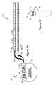
- FIG. 3shows an external controller/charger system in accordance with an embodiment of the invention comprising an external controller with a detachable external charging coil assembly.
- FIG. 4shows the internal components of the external controller of FIG. 3 .
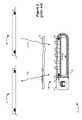
- FIG. 5shows another embodiment of an external controller/charger system in which the external controller comprises a single power, data, and external charging coil assembly port.
- the description that followsrelates to use of the invention within a spinal cord stimulation (SCS) system.
- the inventionis not so limited. Rather, the invention may be used with any type of implantable medical device system that could benefit from improved coupling between an external device and the implanted device.
- the present inventionmay be used as part of a system employing an implantable sensor, an implantable pump, a pacemaker, a defibrillator, a cochlear stimulator, a retinal stimulator, a stimulator configured to produce coordinated limb movement, a cortical and deep brain stimulator, or in any other neural stimulator configured to treat any of a variety of conditions.
- FIG. 3One embodiment of an improved external controller/charger system 200 is illustrated in FIG. 3 .
- the system 200comprises two main components: an external controller 210 and an external charging coil assembly 220 that is coupleable thereto.
- the system 200can be used to both send and receive data telemetry to and from the IPG 100 , and to send power to the IPG 100 .
- the external controller 210controls data telemetry by energizing at least one coil 62 a or 62 b ( FIG. 4 ) within the external controller 210 , and the external controller 210 controls power transmission by energizing a charging coil 250 in the external charging coil assembly 220 , which is otherwise devoid of its own control, power, and user interface.
- Allowing the external charging coil assembly 220 to be attached to and detached from the external controller 210achieves good integration of the charging and data telemetry functions in an implantable medical device system, and comprises a solution that mitigates many of the problems discussed in the Background.
- the external charging coil assembly 220does not contain a substantial amount of electronics, such as its own display, battery, microcontroller, etc., it is less bulky and easier to carry in conjunction with the external controller 210 .
- the external charging coil assembly 220lacks its own user interface, which instead is integrated as part of the user interface of the external controller 210 . This makes the system 200 easier to use, as the patient does not need to learn how to use or manipulate two completely independent devices. Because the external controller 210 powers both itself and the external charging coil assembly 220 , there is only one battery to replace and/or recharge. The result is a cheaper, simpler, more compact, and more convenient data telemetry and charging solution for the patient having a medical implant.
- Housing 215 of the controller 210contains an additional port 225 into which a connector 230 on the charging coil assembly 220 can be placed.
- the connector 230is connected by a cable 235 to a charging coil housing 240 portion of the assembly 220 .
- the charging coil housing 240contains the charging coil 250
- the external controller housing 215contains the data telemetry coils 62 a and 62 b , which are disclosed in FIG. 4 and will be discussed later.
- the charging coil housing 240is roughly donut shaped to accommodate the circular shape of the charging coil 250 , but the shape can vary.
- the charging coil housing 240can be disc shaped and thus can lack a central hole.
- the charging coil 250is preferably comprised of Litz wire, such as 25/38 Litz wire (in which each wire contains 25 individually-insulated strands of 38 gauge wire) or 50/41 Litz wire (50 individually-insulated strands of 41 gauge wire).
- the charging coil 250exhibits an inductance of approximately 400 microhenries, which can be achieved by using approximately 75 turns of 25/38 Litz wire wound with a coil diameter (CD) of 5.5 cm.
- CDcoil diameter
- the coil diameter (CD)is preferably made large to maximize the reliability of coupling with the corresponding charging coil 18 in the IPG (see FIG. 2 ).
- a larger coil diameterwill require more power, which will increase the draw from the battery 126 in the external controller 210 . (The controller 210 's battery 126 will be discussed in further detail below).
- the external charging coil assembly 220can be assembled in many different ways, and one method for forming a flexible assembly is explained in detail here. As best seen in cross-section in FIG. 3 , assembly can begin with a substrate 255 for holding the electronic components, such as the charging coil 250 and temperature-sensing thermistors 260 , discussed further below.
- the substrate 255if used, is preferably flexible and comprises any type of flexible substrates used to carry electronic circuitry, such as Kapton or Polyimide.
- the charging coil 250is wound to the specified number of turns, and is wound concurrently with the deposition of a silicone, such that the resulting coil 250 comprises wire windings in a flexible, insulative matrix of silicone.
- thermistors 260are placed on the substrate and attached to appropriate lead wires 265 leading towards the cable 235 .
- the thermistors 260are designed to sense the temperature of the charging coil housing 240 during charging, i.e., when the charging coil 250 is energized, to ensure that a safe temperatures are maintained.
- the thermistors 260can report the temperature back to the external controller 210 , which in turn can temporarily disable further charging if the temperature is excessive (e.g., over 41 C or approximately 106 F).
- Thermistors 260however are not strictly mandatory, and further can vary in number. For example, as shown in FIG.
- thermistors 260can appear on the top or bottom of the substrate 255 (as shown in the cross section) or on opposing sides of the housing 240 (as shown in the planar view). If the housing 240 is disk shaped, the substrate 255 can likewise be disc shaped, and the thermistors 260 could in that arrangement be alternatively or additionally located in the middle of the housing.
- the lead wiresare connected to wires in the cable 235 .
- the charge coil housing 240is mold injected around the resulting substrate 255 .
- Siliconeis preferred as the fill material for the mold injection process, because it yields a charge coil housing 240 that is soft and flexible.
- the resultis a charge coil housing 240 that is comfortable and can conform to the patient's body. This is especially important in an application where the patient must sit or otherwise place weight on the housing 240 to place it in a proper alignment with the IPG 100 while charging.
- the particular size of the charge coil housing 240is not particularly important, but in one embodiment can comprise an inner diameter (ID) of 4.0 cm, an outer diameter (OD) of 7.0 cm, and a thickness (t) of 3.0 mm.
- the substrate 255can be useful to stabilize the charging coil 250 and any associated electronics (e.g., temperature sensors 260 ) prior to mold injection of the silicone, a substrate 255 is not strictly required. Mold injection of the housing 240 to encapsulate these components can occur even without the benefit of a substrate 255 .
- the external controller 210 controllerand integrates data telemetry and charging functionality via its microcontroller and software (not shown), and provides the user access to such functionality through a user interface.
- the user interfacegenerally allows the user to telemeter data (such as a new therapy program) from the external controller 210 to the IPG 100 , to charge the battery 26 in the IPG, or to monitor various forms of status feedback from the IPG.
- the user interfaceis somewhat similar to a cell phone or to other external controllers used in the art, in that it includes a display 265 , an enter or select button 270 , and menu navigation buttons 272 .
- Soft keys 278can be used to select various functions, which functions will vary depending on the status of the menu options available at any given time.
- a speakeris also included within the housing 215 to provide audio cues to the user (not shown).
- a vibration motorcan provide feedback for users with hearing impairments.
- Unlock button 281recessed into the side of the housing, can be used to unlock the keys and buttons, and can be activated by pressing and holding that button for some duration of time (e.g., one second).
- the display 265optimally displays both text and graphics to convey necessary information to the patient such as menu options, stimulation settings, IPG battery status, external controller battery status, or to indicate if stimulation is on or off, or to indicate the status of charging.
- the display 265may comprise a monochrome liquid crystal display (LCD) using twisted nematic (TN) or super twisted nematic (STN) liquid crystal technology.
- LCDmonochrome liquid crystal display
- TNtwisted nematic
- STNsuper twisted nematic
- the advantages of monochrome TN or STN LCDsare low cost, low power, and ease of programming.
- disadvantagessuch as a relatively low resolution, narrow viewing angle (typically only 60 degrees), low contrast, low brightness, and slow response times.
- Brightness and contrastcan be improved with a backlight, but this may increase cost, power consumption, complexity, and electromagnetic interference (EMI), especially in displays 265 with electroluminescent (EL) backlights, which require special high frequency and high voltage drive circuitry.
- LED backlightsrequire lower voltages and are well-suited for minimizing electrical noise.
- the display 265may also comprise a color display such as a color super twisted nematic (CSTN) or thin-film transistor (TFT) LCDs.
- CSTN and TFT LCDsprovide higher resolution, wider viewing angles, higher contrast, higher brightness, and faster response times.
- CSTN and TFT LCDscan range from 8-bit color displays (256 colors) to as high as 32-bit color displays (4.29 billion colors).
- Color LCDsare typically backlit with white light-emitting diodes (LEDs) which are low cost, low in EMI, more reliable, and simpler to implement than traditional EL backlights.
- CSTN and TFT LCDscan also be made such that a backlight is not needed if ambient light is sufficient. This type of transreflective LCD can be visible even in direct sunlight.
- the display 265may further comprise an organic light-emitting diode (OLED) display.
- OLED displaysare available in monochrome, grayscale (typically 4-bit), color (usually two or three colors), or full-color (8-bit to 32-bit color). OLED displays inherently have higher contrast (typically 5000:1) and wider viewing angles (nearly 180 degrees) when compared with color LCDs. OLEDs differ from color LCDs in that OLEDs are emissive (light-emitting) instead of transmissive (light-filtering). In this regard, OLEDs emit light when a voltage is applied across an active material (e.g., an organic polymer), whereas LCDs require color filters and a white backlight to produce color.
- an active materiale.g., an organic polymer
- OLED displayscan be made significantly thinner than color LCDs, which in turn means that the external controller 210 can be made smaller.
- a typical image displayed on an OLED displayrequires less power than a comparable image on a color LCD.
- OLED displaysare also potentially lower in cost than LCDs because, as mentioned, a backlight is not necessary, which can be a significant portion of the display's cost.
- the internal structure of the external controller 210is shown in FIG. 4 .
- a printed circuit board (PCB) 120is central to the internal construction of the controller 210 .
- the front side of the PCB 120carries aspects of the user interface, including the display 265 and pressure-sensitive switches 122 for receiving presses to the various user interface buttons 270 , 272 , 274 , and 276 ( FIG. 3 ).
- the telemetry coils 62 a and 62 b and the battery 126are located on the back side of the PCB 120 , along with other integrated and discrete components necessary to implement the functionality of the external controller, such as the microcontroller and firmware holding the operation system software.
- the external controller 210would also contain the stimulation circuitry for energizing the charging coil 250 , which circuitry would be similar to that traditionally found in a discrete external charger 50 ( FIG. 2 ).
- the battery 126can comprise standard disposable alkaline batteries (e.g., two to four AA or AAA batteries). However, in a preferred embodiment, the battery 126 is rechargeable, which reduces battery costs and waste. In particular, a Lithium (Li)-ion battery or a Li-ion polymer battery is preferred for the battery 126 . Such batteries have high cell voltages (e.g., 4.2V), such that one cell can replace numerous alkaline cells in series. Such batteries also have high energy capacity, which can be nearly twice that of alkaline cells. A rechargeable Li-ion or Li-ion polymer battery 126 thus either allows for twice the runtime of alkaline cells in the same form factor, or the same runtime with about half the package size, which enables a smaller external controller 210 design.
- Li-ion battery or Li-ion polymer battery 126thus either allows for twice the runtime of alkaline cells in the same form factor, or the same runtime with about half the package size, which enables a smaller external controller
- Li-ion or Li-ion polymer batteriesfor the battery 126 also promotes the use of higher-current drain components in the external controller 210 such as the color LCD or OLED displays 265 discussed earlier, which improve patient experience by offering a more legible display.
- higher-current drain componentsin the external controller 210 such as the color LCD or OLED displays 265 discussed earlier, which improve patient experience by offering a more legible display.
- significantly higher current drainscan be achieved, which improves functions requiring high amounts of current, such as energizing the telemetry coils 62 a / 62 b or the charging coil 250 in the external charging coil assembly 220 .
- the communication rangeis increased.
- Li-ion and Li-ion polymer batteriesshould typically remain reliable for the life of the external controller 210 , which means the battery 126 can be sealed in the housing 215 of the external controller 210 . In other words, no opening needs to be made on the housing to allow a user to remove the battery 126 , which improves reliability, safety, and lowers manufacturing costs. Having said this, a latched battery opening can also be provided in the housing 215 of the external controller 210 even when a rechargeable battery 126 is used to allow for battery servicing if needed.
- the battery 126can be recharged much like a cellular telephone, and so can essentially be plugged into a 120V AC wall outlet.
- a power port 280( FIG. 3 ) can receive power using an AC power source 292 (e.g., a wall plug), which is rectified to DC levels by an AC-DC adapter 291 .
- the housing 215 of the external controller 210can carry two electrodes to allow the battery 126 to be charged while sitting in a charging cradle or docking station (not shown).
- the two telemetry coils 62 a and 62 bare respectively wrapped around axes 54 a and 54 b which are orthogonal. More specifically, coil 62 a is wrapped in a racetrack configuration around the back of the PCB 120 , while coil 62 b is wrapped around a ferrite core 128 and affixed to the PCB 120 by epoxy. Further discussion of the benefits of orthogonally-oriented telemetry coils 62 a and 62 b can be found in U.S. patent application Ser. No. 11/853,624, filed Sep. 11, 2007, which is incorporated by reference in its entirety.
- the two coils 62 a , 62 bare driven (for example, with FSK-modulated data) out of phase, preferably at 90 degrees out of phase. This produces a magnetic field which rotates, and which reduces nulls in the coupling between the external controller 210 and the telemetry coil 13 in the IPG 100 .
- the two coilsare used in conjunction with receiver circuitry which likewise phase shifts the received modulated data signals from each coil and presents their sum to typical demodulation circuitry. Because the details of transmission and reception using two orthogonal coils 62 a and 62 b are disclosed in detail in the '624 application, they are not reiterated here.
- coil 62 acan be used exclusively for data transmissions, with coil 62 b dispensed with altogether.
- an antenna or antennassuch as might be used in other forms of wireless devices, may more generically be used in place of the telemetry coil(s) 62 s and/or 62 b .
- the means for telemetry in the external controller 210need not comprise a coil or coils per se, and coils should be understood as one type of more generic antennas which can otherwise be used.
- the external controller 210controls both data telemetry and charging functions, and therefore the user interface (the display 265 , the various buttons 270 - 276 , etc.) provides access to and feedback from both of these functions.
- the software in the controller 210(preferably implemented as microcode accessible by the controller 210 's microcontroller) accordingly provides logical menu options to the display 265 .
- the display 265may provide selectable options for the user to either program or charge the IPG 100 . If the user decides to program the IPG 100 , the software would provide selectable options to allow the patient options to modify therapy, such as by altering the electrodes to be stimulated, the amplitude or frequency of such stimulation, etc.
- the external controllermay investigate port 225 to see if the external charging coil assembly 220 is attached. If not, a suitable message might be displayed instructing the user to so attach the assembly before proceeding further in the menu.
- a data port 282is provided to allow the external controller 210 to communicate with other devices such as a computer 295 .
- a data port 282is useful for example to share data with another machine, to allow the external controller 210 to receive software updates, or to allow the external programmer 210 to receive a starter therapy program from a clinician programmer.
- Data port 282can be physically configured in any number of standard ways, and can be located in many different positions on the housing 240 of the external controller.
- data port 282can be configured as dictated by any number of communication protocols, such as RS323 protocol.
- data port 282comprises an infrared port capable of wireless communication in accordance with the IRDA (Infrared Data Association) protocol. This type of port is useful because it is electrically and mechanically sealed, which reduces the possibility of potential electrical shock to the user.
- IRDAInfrared Data Association
- FIG. 5Another embodiment of the improved external controller/charger system 200 ′ is illustrated in FIG. 5 .
- This embodimentis otherwise similar to system 200 discussed earlier, except as concerns the various ports on the housing 215 of the external controller 210 .
- the power, data, and external charging coil assembly ports 280 , 282 , and 225have been replaced by a single USB port 300 .
- the USB port 300can comprise any USB receptacle profile, such as a micro USB plug receptacle, a mini USB plug receptacle, an A-type plug receptacle, or a B-type plug receptacle.
- the external controller 210can be coupled to the external charging coil assembly 305 by a matching USB connector 305 . Additionally, and beneficially, this same port 300 can connect with other devices, such as a computer 312 via a USB connector 310 , or a AC power source 317 via a USB connector 315 and an AC-DC adapter 316 . Therefore, using the same port 300 as that used to connect the external charging coil assembly 220 , the external controller 210 can be coupled to a power source and to a data source. For example, because USB protocols call for provision of DC power, either the computer 312 or the power source 317 may be used to provide power to the external controller 210 , or more importantly to recharge its battery 126 . Moreover, the computer 312 can be used to download programs to the external controller 210 via the USB port, or to receive status data from the external controller 210 as already explained.
- USBis dictated by its own communication protocol, it is a routine matter for designers to implement communications, and such details do not require repeating here. Although use of a USB port 300 and accompanying USB protocol is preferred, any other type of standardized port and protocol could be used to integrate the power, data, and external charging coil functions described herein.
Landscapes
- Health & Medical Sciences (AREA)
- Engineering & Computer Science (AREA)
- Biomedical Technology (AREA)
- Nuclear Medicine, Radiotherapy & Molecular Imaging (AREA)
- Radiology & Medical Imaging (AREA)
- Life Sciences & Earth Sciences (AREA)
- Animal Behavior & Ethology (AREA)
- General Health & Medical Sciences (AREA)
- Public Health (AREA)
- Veterinary Medicine (AREA)
- Physics & Mathematics (AREA)
- Electromagnetism (AREA)
- Acoustics & Sound (AREA)
- Charge And Discharge Circuits For Batteries Or The Like (AREA)
- Electrotherapy Devices (AREA)
Abstract
Description
Claims (8)
Priority Applications (8)
| Application Number | Priority Date | Filing Date | Title |
|---|---|---|---|
| US11/935,111US8498716B2 (en) | 2007-11-05 | 2007-11-05 | External controller for an implantable medical device system with coupleable external charging coil assembly |
| AU2008325058AAU2008325058A1 (en) | 2007-11-05 | 2008-08-12 | External controller for an implantable medical device system with coupleable external charging coil assembly |
| EP08797689.0AEP2217326B1 (en) | 2007-11-05 | 2008-08-12 | External controller for an implantable medical device system with coupleable external charging coil assembly |
| PCT/US2008/072885WO2009061537A1 (en) | 2007-11-05 | 2008-08-12 | External controller for an implantable medical device system with coupleable external charging coil assembly |
| CA2701496ACA2701496A1 (en) | 2007-11-05 | 2008-08-12 | External controller for an implantable medical device system with coupleable external charging coil assembly |
| JP2010533132AJP2011502634A (en) | 2007-11-05 | 2008-08-12 | External controller for implantable medical device with connectable external charging coil assembly |
| ES08797689.0TES2605560T3 (en) | 2007-11-05 | 2008-08-12 | External controller for an implantable medical device system with an external load coil assembly that can be attached |
| JP2013121082AJP2013176634A (en) | 2007-11-05 | 2013-06-07 | External controller for implantable medical device with couplable external charging coil assembly |
Applications Claiming Priority (1)
| Application Number | Priority Date | Filing Date | Title |
|---|---|---|---|
| US11/935,111US8498716B2 (en) | 2007-11-05 | 2007-11-05 | External controller for an implantable medical device system with coupleable external charging coil assembly |
Publications (2)
| Publication Number | Publication Date |
|---|---|
| US20090118796A1 US20090118796A1 (en) | 2009-05-07 |
| US8498716B2true US8498716B2 (en) | 2013-07-30 |
Family
ID=40032385
Family Applications (1)
| Application Number | Title | Priority Date | Filing Date |
|---|---|---|---|
| US11/935,111Expired - Fee RelatedUS8498716B2 (en) | 2007-11-05 | 2007-11-05 | External controller for an implantable medical device system with coupleable external charging coil assembly |
Country Status (7)
| Country | Link |
|---|---|
| US (1) | US8498716B2 (en) |
| EP (1) | EP2217326B1 (en) |
| JP (2) | JP2011502634A (en) |
| AU (1) | AU2008325058A1 (en) |
| CA (1) | CA2701496A1 (en) |
| ES (1) | ES2605560T3 (en) |
| WO (1) | WO2009061537A1 (en) |
Cited By (62)
| Publication number | Priority date | Publication date | Assignee | Title |
|---|---|---|---|---|
| US8812129B2 (en) | 2009-07-06 | 2014-08-19 | Boston Scientific Neuromodulation Corporation | External device for an implantable medical system having accessible contraindication information |
| WO2014197162A1 (en) | 2013-06-04 | 2014-12-11 | Boston Scientific Neuromodulation Corporation | External device for determining an optimal implantable medical device for a patient using information determined during an external trial stimulation phase |
| US20150073509A1 (en)* | 2011-10-28 | 2015-03-12 | Medtronic, Inc. | Removable heat management for recharge coils |
| US9155898B2 (en) | 2000-03-17 | 2015-10-13 | Boston Scientific Neuromodulation Corporation | Implantable medical device with multi-function single coil |
| US9216294B2 (en) | 2004-06-10 | 2015-12-22 | Medtronic Urinary Solutions, Inc. | Systems and methods for clinician control of stimulation systems |
| WO2016028399A1 (en) | 2014-08-21 | 2016-02-25 | Boston Scientific Neuromodulation Corporation | Use of a dedicated remote control as an intermediary device to communicate with an implantable medical device |
| US9272156B2 (en) | 2009-11-11 | 2016-03-01 | Boston Scientific Neuromodulation Corporation | External controller/charger system for an implantable medical device capable of automatically providing data telemetry through a charging coil during a charging session |
| WO2016069090A1 (en) | 2014-10-30 | 2016-05-06 | Boston Scientific Neuromodulation Corporation | External controller for an implantable medical device system with an external charging coil powered by an external battery |
| US9407110B2 (en) | 2012-07-19 | 2016-08-02 | Boston Scientific Neuromodulation Corporation | Self-affixing external charging system for an implantable medical device |
| US9433796B2 (en) | 2013-09-03 | 2016-09-06 | Boston Scientific Neuromodulation Corporation | Medical device application for an external device using data logged at an implantable medical device |
| WO2016144525A1 (en) | 2015-03-12 | 2016-09-15 | Boston Scientific Neuromodulation Corporation | Assembly with a coaxial audio connector for charging an implantable medical device |
| WO2016148778A1 (en) | 2015-03-19 | 2016-09-22 | Boston Scientific Neuromodulation Corporation | An optical head-mounted display for controlling an implantable medical device and communication accessory attachable thereto |
| WO2016164103A1 (en) | 2015-04-08 | 2016-10-13 | Boston Scientific Neuromodulation Corporation | Charging coil holding device for an implantable medical device coupleable to a controller/charger device |
| US9539435B2 (en) | 2014-09-08 | 2017-01-10 | Medtronic, Inc. | Transthoracic protection circuit for implantable medical devices |
| US9564777B2 (en) | 2014-05-18 | 2017-02-07 | NeuSpera Medical Inc. | Wireless energy transfer system for an implantable medical device using a midfield coupler |
| US9579517B2 (en) | 2014-09-08 | 2017-02-28 | Medtronic, Inc. | Transformer-based charging circuits for implantable medical devices |
| US9604071B2 (en) | 2014-09-08 | 2017-03-28 | Medtronic, Inc. | Implantable medical devices having multi-cell power sources |
| US9610457B2 (en) | 2013-09-16 | 2017-04-04 | The Board Of Trustees Of The Leland Stanford Junior University | Multi-element coupler for generation of electromagnetic energy |
| US9643022B2 (en) | 2013-06-17 | 2017-05-09 | Nyxoah SA | Flexible control housing for disposable patch |
| US9643025B2 (en) | 2014-09-08 | 2017-05-09 | Medtronic, Inc. | Multi-primary transformer charging circuits for implantable medical devices |
| US9707402B2 (en) | 2014-02-14 | 2017-07-18 | Boston Scientific Neuromodulation Corporation | Plug-in accessory for configuring a mobile device into an external controller for an implantable medical device |
| US9724528B2 (en) | 2014-09-08 | 2017-08-08 | Medtronic, Inc. | Multiple transformer charging circuits for implantable medical devices |
| WO2017176475A1 (en) | 2016-04-04 | 2017-10-12 | Boston Scientific Neuromodulation Corporation | System to estimate the location of a spinal cord physiological midline |
| WO2017176474A1 (en) | 2016-04-04 | 2017-10-12 | Boston Scientific Neuromodulation Corporation | System to estimate the location of a spinal cord physiological midline |
| US9849289B2 (en) | 2009-10-20 | 2017-12-26 | Nyxoah SA | Device and method for snoring detection and control |
| US9855032B2 (en) | 2012-07-26 | 2018-01-02 | Nyxoah SA | Transcutaneous power conveyance device |
| US9861828B2 (en) | 2014-09-08 | 2018-01-09 | Medtronic, Inc. | Monitoring multi-cell power source of an implantable medical device |
| US9861827B2 (en) | 2014-09-08 | 2018-01-09 | Medtronic, Inc. | Implantable medical devices having multi-cell power sources |
| US9867994B2 (en) | 2015-06-19 | 2018-01-16 | Boston Scientific Neuromodulation Corporation | External powering of implantable medical device dependent on energy of provided therapy |
| US9943686B2 (en) | 2009-10-20 | 2018-04-17 | Nyxoah SA | Method and device for treating sleep apnea based on tongue movement |
| US10052097B2 (en) | 2012-07-26 | 2018-08-21 | Nyxoah SA | Implant unit delivery tool |
| WO2018160329A1 (en) | 2017-02-28 | 2018-09-07 | Boston Scientific Neuromodulation Corporation | Implantable medical device with a silicone housing |
| WO2018175005A1 (en) | 2017-03-21 | 2018-09-27 | Boston Scientific Neuromodulation Corporation | External charger with three-axis magnetic field sensor to determine implantable medical device position |
| WO2018200081A1 (en) | 2017-04-24 | 2018-11-01 | Boston Scientific Neuromodulation Corporation | Technique to ensure security for connected implantable medical devices |
| US10226637B2 (en) | 2016-06-15 | 2019-03-12 | Boston Scientific Neuromodulation Corporation | External charger for an implantable medical device having alignment and centering capabilities |
| US10322288B2 (en) | 2011-10-28 | 2019-06-18 | Medtronic, Inc. | Heat management for recharge coils for implantable medical devices |
| US10342984B2 (en) | 2016-06-15 | 2019-07-09 | Boston Scientific Neuromodulation Corporation | Split coil for uniform magnetic field generation from an external charger for an implantable medical device |
| US10363426B2 (en) | 2016-06-15 | 2019-07-30 | Boston Scientific Neuromodulation Corporation | External charger for an implantable medical device for determining position using phase angle or a plurality of parameters as determined from at least one sense coil |
| US10406368B2 (en) | 2016-04-19 | 2019-09-10 | Boston Scientific Neuromodulation Corporation | Pulse generator system for promoting desynchronized firing of recruited neural populations |
| US10420950B2 (en) | 2015-11-29 | 2019-09-24 | Boston Scientific Neuromodulation Corporation | Implantable pulse generator usable during a trial stimulation phase and externally powered by magnetic inductive coupling |
| WO2019231794A1 (en) | 2018-06-01 | 2019-12-05 | Boston Scientific Neuromodulation Corporation | Interleaving stimulation patterns provided by an implantable pulse generator |
| US10576292B2 (en) | 2015-11-29 | 2020-03-03 | Boston Scientific Neuromodulation Corporation | Skull-mounted deep brain stimulator |
| US10603501B2 (en) | 2016-06-15 | 2020-03-31 | Boston Scientific Neuromodulation Corporation | External charger for an implantable medical device having at least one sense coil concentric with a charging coil for determining position |
| US10751537B2 (en) | 2009-10-20 | 2020-08-25 | Nyxoah SA | Arced implant unit for modulation of nerves |
| US10814137B2 (en) | 2012-07-26 | 2020-10-27 | Nyxoah SA | Transcutaneous power conveyance device |
| US10842989B2 (en) | 2017-11-08 | 2020-11-24 | Boston Scientific Neuromodulation Corporation | System to improve a spinal cord stimulation model based on a physiological midline location |
| US10994146B2 (en) | 2017-12-12 | 2021-05-04 | Boston Scientific Neuromodulation Corporation | External device with electromagnet for use with an implantable medical device |
| US11040209B2 (en) | 2017-01-19 | 2021-06-22 | Boston Scienitific Neuromodulation Corporation | Radio frequency antenna capacitively coupled to a charging coil in an implantable medical device |
| US11116975B2 (en) | 2015-11-09 | 2021-09-14 | Bluewind Medical Ltd. | Optimization of application of current |
| US11129996B2 (en) | 2016-06-15 | 2021-09-28 | Boston Scientific Neuromodulation Corporation | External charger for an implantable medical device for determining position and optimizing power transmission using resonant frequency as determined from at least one sense coil |
| US11173308B2 (en) | 2018-03-05 | 2021-11-16 | Boston Scientific Neuromodulation Corporation | Virtual target pole adjustment based on nerve root trajectory |
| US11213685B2 (en) | 2017-06-13 | 2022-01-04 | Bluewind Medical Ltd. | Antenna configuration |
| US11253712B2 (en) | 2012-07-26 | 2022-02-22 | Nyxoah SA | Sleep disordered breathing treatment apparatus |
| US11273313B2 (en) | 2019-04-18 | 2022-03-15 | Boston Scientific Neuromodulation Corporation | Dynamic visualization of neuronal sub population interactions |
| US11278719B2 (en) | 2012-12-06 | 2022-03-22 | Bluewind Medical Ltd. | Delivery of implantable neurostimulators |
| US11338148B2 (en) | 2015-05-15 | 2022-05-24 | NeuSpera Medical Inc. | External power devices and systems |
| US11400299B1 (en) | 2021-09-14 | 2022-08-02 | Rainbow Medical Ltd. | Flexible antenna for stimulator |
| US11439833B2 (en) | 2016-11-23 | 2022-09-13 | Bluewind Medical Ltd. | Implant-delivery tool |
| US11471692B2 (en) | 2016-06-15 | 2022-10-18 | Boston Scientific Neuromodulation Corporation | External charger for an implantable medical device for adjusting charging power based on determined position using at least one sense coil |
| US11559355B2 (en) | 2018-07-30 | 2023-01-24 | Boston Scientific Neuromodulation Corporation | Augmented and virtual reality for use with neuromodulation therapy |
| US11607163B2 (en) | 2020-01-15 | 2023-03-21 | Medtronic Inc. | Rechargeable cardiac monitor device |
| US11648410B2 (en) | 2012-01-26 | 2023-05-16 | Bluewind Medical Ltd. | Wireless neurostimulators |
Families Citing this family (56)
| Publication number | Priority date | Publication date | Assignee | Title |
|---|---|---|---|---|
| WO2007098200A2 (en) | 2006-02-16 | 2007-08-30 | Imthera Medical, Inc. | An rfid-based apparatus, system, and method for therapeutic treatment of obstructive sleep apnea |
| EP2197536A1 (en) | 2007-10-09 | 2010-06-23 | Imthera Medical, Inc. | System and method for neural stimulation |
| EP2092958B1 (en)* | 2008-02-22 | 2017-05-24 | Cochlear Limited | Interleaving power and data in a transcutaneous communications link |
| EP2349139B1 (en) | 2008-10-09 | 2017-05-31 | Imthera Medical, Inc. | Stimulation of a hypoglossal nerve for controlling the position of a patient's tongue |
| US8751001B2 (en)* | 2008-10-23 | 2014-06-10 | Medtronic, Inc. | Universal recharging of an implantable medical device |
| US8335569B2 (en) | 2009-02-10 | 2012-12-18 | Boston Scientific Neuromodulation Corporation | External device for communicating with an implantable medical device having data telemetry and charging integrated in a single housing |
| US20100277119A1 (en)* | 2009-05-01 | 2010-11-04 | Medtronic Minimed, Inc. | Medical Device Charging System |
| US8214042B2 (en)* | 2009-05-26 | 2012-07-03 | Boston Scientific Neuromodulation Corporation | Techniques for controlling charging of batteries in an external charger and an implantable medical device |
| US20100305663A1 (en)* | 2009-06-02 | 2010-12-02 | Boston Scientific Neuromodulation Corporation | Implantable medical device system having short range communication link between an external controller and an external charger |
| US20100318159A1 (en)* | 2009-06-12 | 2010-12-16 | Boston Scientific Neuromodulation Corporation | Miniature remote controller for implantable medical device |
| JP2011003947A (en)* | 2009-06-16 | 2011-01-06 | Showa Aircraft Ind Co Ltd | Coil communication device |
| US20100331918A1 (en)* | 2009-06-30 | 2010-12-30 | Boston Scientific Neuromodulation Corporation | Moldable charger with curable material for charging an implantable pulse generator |
| US9399131B2 (en)* | 2009-06-30 | 2016-07-26 | Boston Scientific Neuromodulation Corporation | Moldable charger with support members for charging an implantable pulse generator |
| US8260432B2 (en)* | 2009-06-30 | 2012-09-04 | Boston Scientific Neuromodulation Corporation | Moldable charger with shape-sensing means for an implantable pulse generator |
| US20100331919A1 (en)* | 2009-06-30 | 2010-12-30 | Boston Scientific Neuromodulation Corporation | Moldable charger having hinged sections for charging an implantable pulse generator |
| US8473066B2 (en) | 2009-07-06 | 2013-06-25 | Boston Scientific Neuromodulation Company | External charger for a medical implantable device using field sensing coils to improve coupling |
| EP4122531A1 (en)* | 2009-07-17 | 2023-01-25 | Implantica Patent Ltd. | Coil system |
| US8321029B2 (en)* | 2009-09-18 | 2012-11-27 | Boston Scientific Neuromodulation Corporation | External charger usable with an implantable medical device having a programmable or time-varying temperature set point |
| US8311638B2 (en)* | 2009-10-15 | 2012-11-13 | Boston Scientific Neuromodulation Corporation | External charger for a medical implantable device using field inducing coils to improve coupling |
| WO2011059531A1 (en) | 2009-11-10 | 2011-05-19 | Imthera Medical, Inc. | System for stimulating a hypoglossal nerve for controlling the position of a patient's tongue |
| US8457756B2 (en) | 2009-11-11 | 2013-06-04 | Boston Scientific Neuromodulation Corporation | Using the case of an implantable medical device to broaden communication bandwidth |
| US8577474B2 (en) | 2009-11-11 | 2013-11-05 | Boston Scientific Neuromodulation Corporation | Minimizing interference between charging and telemetry coils in an implantable medical device |
| US8401663B2 (en)* | 2010-01-19 | 2013-03-19 | Boston Scientific Neuromodulation Corporation | Pressure-sensitive external charger for an implantable medical device |
| AU2013202343B2 (en)* | 2010-01-19 | 2014-07-03 | Boston Scientific Neuromodulation Corporation | Pressure-sensitive external charger for an implantable medical device |
| WO2011097289A1 (en) | 2010-02-03 | 2011-08-11 | Medtronic, Inc. | Implantable medical devices and systems having dual frequency inductive telemetry and recharge |
| US9042995B2 (en)* | 2010-02-03 | 2015-05-26 | Medtronic, Inc. | Implantable medical devices and systems having power management for recharge sessions |
| US9030159B2 (en) | 2010-03-26 | 2015-05-12 | Boston Scientific Neuromodulation Corporation | Inductive charger with magnetic shielding |
| US9216297B2 (en) | 2010-04-05 | 2015-12-22 | Medtronic, Inc. | Flexible recharge coil techniques |
| US8594806B2 (en) | 2010-04-30 | 2013-11-26 | Cyberonics, Inc. | Recharging and communication lead for an implantable device |
| US8933944B2 (en) | 2010-10-13 | 2015-01-13 | Boston Scientific Neuromodulation Corporation | External controller for an implantable medical device with dual microcontrollers for improved graphics rendering |
| CN103328041B (en)* | 2010-10-19 | 2016-03-16 | 耳蜗有限公司 | Relay interface for connecting implantable medical devices to external electronics |
| US20120101551A1 (en)* | 2010-10-25 | 2012-04-26 | Boston Scientific Neuromodulation Corporation | External Controller For an Implantable Medical Device Formed Using a Sub-Assembly |
| US8634927B2 (en) | 2011-01-28 | 2014-01-21 | Medtronic, Inc. | Medical device recharge systems using a controller in wireless communication with a separate recharge device |
| US10286217B2 (en) | 2011-01-28 | 2019-05-14 | Medtronic, Inc. | Far field telemetry communication with a medical device during a recharge session where a prior pairing with the medical device may not exist |
| US8712541B2 (en) | 2011-01-28 | 2014-04-29 | Medtronic, Inc. | Far field telemetry operations between an external device and an implantable medical device during recharge of the implantable medical device via a proximity coupling |
| US9136728B2 (en) | 2011-04-28 | 2015-09-15 | Medtronic, Inc. | Implantable medical devices and systems having inductive telemetry and recharge on a single coil |
| US20130197607A1 (en)* | 2011-06-28 | 2013-08-01 | Greatbatch Ltd. | Dual patient controllers |
| US8954148B2 (en) | 2011-06-28 | 2015-02-10 | Greatbatch, Ltd. | Key fob controller for an implantable neurostimulator |
| US20130006330A1 (en) | 2011-06-28 | 2013-01-03 | Greatbatch, Ltd. | Dual patient controllers |
| US9446254B2 (en) | 2011-10-13 | 2016-09-20 | Boston Scientific Neuromodulation Corporation | Charger alignment in an implantable medical device system employing reflected impedance modulation |
| US9314642B2 (en) | 2011-10-13 | 2016-04-19 | Boston Scientific Neuromodulation Corporation | Closed loop charger for an implantable medical device system employing reflected impedance modulation |
| US20130110203A1 (en)* | 2011-10-27 | 2013-05-02 | Boston Scientific Neuromodulation Corporation | Managing a Multi-function Coil in an Implantable Medical Device Using an Optical Switch |
| US20130123881A1 (en) | 2011-11-11 | 2013-05-16 | Boston Scientific Neuromodulation Corporation | External Charger for an Implantable Medical Device System Having a Coil for Communication and Charging |
| WO2013095799A1 (en)* | 2011-12-21 | 2013-06-27 | Boston Scientific Neuromodulation Corporation | A system for an implantable medical device having an external charger coupleable to accessory charging coils |
| JP2014018508A (en)* | 2012-07-20 | 2014-02-03 | Tohoku Univ | Automatic nerve control device and renal sympathetic nerve control device |
| US8761717B1 (en) | 2012-08-07 | 2014-06-24 | Brian K. Buchheit | Safety feature to disable an electronic device when a wireless implantable medical device (IMD) is proximate |
| US9186518B2 (en) | 2013-09-06 | 2015-11-17 | Boston Scientific Neuromodulation Corporation | Medical device application for configuring a mobile device into an external controller for an implantable medical device |
| US9339660B2 (en) | 2013-10-04 | 2016-05-17 | Boston Scientific Neuromodulation Corporation | Implantable medical device with one or more magnetic field sensors to assist with external charger alignment |
| EP3069358B1 (en)* | 2013-11-11 | 2019-06-12 | Tc1 Llc | Hinged resonant power transfer coil |
| EP3131601B1 (en) | 2014-04-15 | 2018-07-25 | Heartware, Inc. | Improvements in transcutaneous energy transfer systems |
| US10348891B2 (en) | 2015-09-06 | 2019-07-09 | Deborah M. Manchester | System for real time, remote access to and adjustment of patient hearing aid with patient in normal life environment |
| WO2017139784A1 (en)* | 2016-02-12 | 2017-08-17 | Axonics Modulation Technologies, Inc. | External pulse generator device and associated methods for trial nerve stimulation |
| US10888706B2 (en)* | 2017-06-02 | 2021-01-12 | Boston Scientific Neuromodulation Corporation | External charger for an implantable medical device having a thermal diffuser |
| US10821292B2 (en)* | 2018-06-28 | 2020-11-03 | Medtronic, Inc. | Multi-axis coil for implantable medical device |
| GB2580330B (en)* | 2018-12-31 | 2021-01-20 | Emda Ltd | Device to electromagnetically stimulate new organic cell proliferation |
| WO2024163228A1 (en)* | 2023-01-31 | 2024-08-08 | Shiratronics, Inc. | System with charging / patient-applied part port |
Citations (18)
| Publication number | Priority date | Publication date | Assignee | Title |
|---|---|---|---|---|
| US5314457A (en) | 1993-04-08 | 1994-05-24 | Jeutter Dean C | Regenerative electrical |
| US6505077B1 (en) | 2000-06-19 | 2003-01-07 | Medtronic, Inc. | Implantable medical device with external recharging coil electrical connection |
| US6516227B1 (en) | 1999-07-27 | 2003-02-04 | Advanced Bionics Corporation | Rechargeable spinal cord stimulator system |
| US6553263B1 (en) | 1999-07-30 | 2003-04-22 | Advanced Bionics Corporation | Implantable pulse generators using rechargeable zero-volt technology lithium-ion batteries |
| US6658300B2 (en) | 2000-12-18 | 2003-12-02 | Biosense, Inc. | Telemetric reader/charger device for medical sensor |
| JP2004073725A (en) | 2002-08-22 | 2004-03-11 | Nikkiso Co Ltd | Percutaneous energy transfer device |
| US20040098068A1 (en)* | 2002-06-28 | 2004-05-20 | Rafael Carbunaru | Chair pad charging and communication system for a battery-powered microstimulator |
| WO2005032658A1 (en) | 2003-10-02 | 2005-04-14 | Medtronic, Inc. | User interface for external charger for implantable medical device |
| US20050088357A1 (en) | 2003-10-24 | 2005-04-28 | Medtronic Minimed, Inc. | System and method for multiple antennas having a single core |
| US20050143781A1 (en) | 2003-01-31 | 2005-06-30 | Rafael Carbunaru | Methods and systems for patient adjustment of parameters for an implanted stimulator |
| US20050187590A1 (en)* | 2003-05-11 | 2005-08-25 | Boveja Birinder R. | Method and system for providing therapy for autism by providing electrical pulses to the vagus nerve(s) |
| WO2007012432A1 (en) | 2005-07-29 | 2007-02-01 | Hexion Specialty Chemicals Research Belgium S.A. | Structured polymer based aqueous dispersion, method for obtaining same and uses thereof in formulations for paints |
| US20070060980A1 (en) | 2004-06-10 | 2007-03-15 | Ndi Medical, Llc | Implantable pulse generator systems and methods for providing functional and/or therapeutic stimulation of muscles and/or nerves and/or central nervous system tissue |
| US20070060967A1 (en) | 2004-06-10 | 2007-03-15 | Ndi Medical, Llc | Implantable pulse generator systems and methods for providing functional and /or therapeutic stimulation of muscles and/or nerves and/or central nervous system tissue |
| US7200504B1 (en) | 2005-05-16 | 2007-04-03 | Advanced Bionics Corporation | Measuring temperature change in an electronic biomedical implant |
| US7286880B2 (en) | 2003-10-02 | 2007-10-23 | Medtronic, Inc. | System and method for transcutaneous energy transfer achieving high efficiency |
| WO2007124325A2 (en)* | 2006-04-21 | 2007-11-01 | Advanced Bionics Corporation | Cochlear stimulation device |
| US20070270921A1 (en)* | 2006-05-17 | 2007-11-22 | Ndi Medical, Inc. | Systems and methods for patient control of stimulation systems |
Family Cites Families (6)
| Publication number | Priority date | Publication date | Assignee | Title |
|---|---|---|---|---|
| JPH05317433A (en)* | 1992-05-26 | 1993-12-03 | Kaajio P-Shingu Res Lab:Kk | Pace maker |
| US7167756B1 (en)* | 2000-04-28 | 2007-01-23 | Medtronic, Inc. | Battery recharge management for an implantable medical device |
| JP4643447B2 (en)* | 2003-07-24 | 2011-03-02 | 日本電信電話株式会社 | Image encoding device, image decoding device, image encoding method, and image decoding method |
| ATE520440T1 (en)* | 2004-02-12 | 2011-09-15 | Ndi Medical Llc | WEARABLE ARRANGEMENTS AND SYSTEMS FOR FUNCTIONAL OR THERAPEUTIC NEUROMUSCULAR STIMULATION |
| US7493167B2 (en)* | 2005-03-22 | 2009-02-17 | Greatbatch-Sierra, Inc. | Magnetically shielded AIMD housing with window for magnetically actuated switch |
| US7856264B2 (en)* | 2005-10-19 | 2010-12-21 | Advanced Neuromodulation Systems, Inc. | Systems and methods for patient interactive neural stimulation and/or chemical substance delivery |
- 2007
- 2007-11-05USUS11/935,111patent/US8498716B2/ennot_activeExpired - Fee Related
- 2008
- 2008-08-12AUAU2008325058Apatent/AU2008325058A1/ennot_activeAbandoned
- 2008-08-12WOPCT/US2008/072885patent/WO2009061537A1/enactiveApplication Filing
- 2008-08-12CACA2701496Apatent/CA2701496A1/ennot_activeAbandoned
- 2008-08-12EPEP08797689.0Apatent/EP2217326B1/ennot_activeNot-in-force
- 2008-08-12ESES08797689.0Tpatent/ES2605560T3/enactiveActive
- 2008-08-12JPJP2010533132Apatent/JP2011502634A/enactivePending
- 2013
- 2013-06-07JPJP2013121082Apatent/JP2013176634A/enactivePending
Patent Citations (19)
| Publication number | Priority date | Publication date | Assignee | Title |
|---|---|---|---|---|
| US5314457A (en) | 1993-04-08 | 1994-05-24 | Jeutter Dean C | Regenerative electrical |
| US6516227B1 (en) | 1999-07-27 | 2003-02-04 | Advanced Bionics Corporation | Rechargeable spinal cord stimulator system |
| US6553263B1 (en) | 1999-07-30 | 2003-04-22 | Advanced Bionics Corporation | Implantable pulse generators using rechargeable zero-volt technology lithium-ion batteries |
| US6505077B1 (en) | 2000-06-19 | 2003-01-07 | Medtronic, Inc. | Implantable medical device with external recharging coil electrical connection |
| US6658300B2 (en) | 2000-12-18 | 2003-12-02 | Biosense, Inc. | Telemetric reader/charger device for medical sensor |
| US20040098068A1 (en)* | 2002-06-28 | 2004-05-20 | Rafael Carbunaru | Chair pad charging and communication system for a battery-powered microstimulator |
| JP2004073725A (en) | 2002-08-22 | 2004-03-11 | Nikkiso Co Ltd | Percutaneous energy transfer device |
| US20050143781A1 (en) | 2003-01-31 | 2005-06-30 | Rafael Carbunaru | Methods and systems for patient adjustment of parameters for an implanted stimulator |
| US20050187590A1 (en)* | 2003-05-11 | 2005-08-25 | Boveja Birinder R. | Method and system for providing therapy for autism by providing electrical pulses to the vagus nerve(s) |
| US7286880B2 (en) | 2003-10-02 | 2007-10-23 | Medtronic, Inc. | System and method for transcutaneous energy transfer achieving high efficiency |
| WO2005032658A1 (en) | 2003-10-02 | 2005-04-14 | Medtronic, Inc. | User interface for external charger for implantable medical device |
| US20050113887A1 (en) | 2003-10-02 | 2005-05-26 | Medtronic, Inc. | User interface for external charger for implantable medical device |
| US20050088357A1 (en) | 2003-10-24 | 2005-04-28 | Medtronic Minimed, Inc. | System and method for multiple antennas having a single core |
| US20070060980A1 (en) | 2004-06-10 | 2007-03-15 | Ndi Medical, Llc | Implantable pulse generator systems and methods for providing functional and/or therapeutic stimulation of muscles and/or nerves and/or central nervous system tissue |
| US20070060967A1 (en) | 2004-06-10 | 2007-03-15 | Ndi Medical, Llc | Implantable pulse generator systems and methods for providing functional and /or therapeutic stimulation of muscles and/or nerves and/or central nervous system tissue |
| US7200504B1 (en) | 2005-05-16 | 2007-04-03 | Advanced Bionics Corporation | Measuring temperature change in an electronic biomedical implant |
| WO2007012432A1 (en) | 2005-07-29 | 2007-02-01 | Hexion Specialty Chemicals Research Belgium S.A. | Structured polymer based aqueous dispersion, method for obtaining same and uses thereof in formulations for paints |
| WO2007124325A2 (en)* | 2006-04-21 | 2007-11-01 | Advanced Bionics Corporation | Cochlear stimulation device |
| US20070270921A1 (en)* | 2006-05-17 | 2007-11-22 | Ndi Medical, Inc. | Systems and methods for patient control of stimulation systems |
Non-Patent Citations (8)
| Title |
|---|
| Advanced Neuromodulation Systems (ANS), Inc. Eon(TM) Neurostimulation Systems IPG, as described in Applicant's Information Disclosure Statement filed herewith. |
| Advanced Neuromodulation Systems (ANS), Inc. Eon™ Neurostimulation Systems IPG, as described in Applicant's Information Disclosure Statement filed herewith. |
| Examiner's first report regarding corresponding Australian patent application No. 2008325058, dated Feb. 3, 2011. |
| International Search Report regarding application No. PCT/US2008/072885 dated Dec. 12, 2008. |
| Medtronic, Inc.'s Restore(TM) Rechargeable Neurostimulation System, as described in Applicant's Information Disclosure Statement filed herewith. |
| Medtronic, Inc.'s Restore™ Rechargeable Neurostimulation System, as described in Applicant's Information Disclosure Statement filed herewith. |
| U.S. Appl. No. 11/780,369, filed Jul. 19, 2007, Dronov. |
| U.S. Appl. No. 11/853,624, filed Sep. 11, 2007, Stouffer. |
Cited By (126)
| Publication number | Priority date | Publication date | Assignee | Title |
|---|---|---|---|---|
| US9155898B2 (en) | 2000-03-17 | 2015-10-13 | Boston Scientific Neuromodulation Corporation | Implantable medical device with multi-function single coil |
| US9446250B2 (en) | 2000-03-17 | 2016-09-20 | Boston Scientific Neuromodulation Corporation | Implantable medical device with multi-function single coil |
| US10293168B2 (en) | 2004-06-10 | 2019-05-21 | Medtronic Urinary Solutions, Inc. | Systems and methods for clinician control of stimulation systems |
| US9216294B2 (en) | 2004-06-10 | 2015-12-22 | Medtronic Urinary Solutions, Inc. | Systems and methods for clinician control of stimulation systems |
| US8812129B2 (en) | 2009-07-06 | 2014-08-19 | Boston Scientific Neuromodulation Corporation | External device for an implantable medical system having accessible contraindication information |
| US8965524B2 (en) | 2009-07-06 | 2015-02-24 | Boston Scientific Neuromodulation Corporation | External device for an implantable medical system having accessible contraindication information |
| US9220909B2 (en) | 2009-07-06 | 2015-12-29 | Boston Scientific Neuromodulation Corporation | External device for an implantable medical system having accessible contraindication information |
| US11273307B2 (en) | 2009-10-20 | 2022-03-15 | Nyxoah SA | Method and device for treating sleep apnea |
| US9950166B2 (en) | 2009-10-20 | 2018-04-24 | Nyxoah SA | Acred implant unit for modulation of nerves |
| US9849289B2 (en) | 2009-10-20 | 2017-12-26 | Nyxoah SA | Device and method for snoring detection and control |
| US10898717B2 (en) | 2009-10-20 | 2021-01-26 | Nyxoah SA | Device and method for snoring detection and control |
| US9943686B2 (en) | 2009-10-20 | 2018-04-17 | Nyxoah SA | Method and device for treating sleep apnea based on tongue movement |
| US11857791B2 (en) | 2009-10-20 | 2024-01-02 | Nyxoah SA | Arced implant unit for modulation of nerves |
| US10716940B2 (en) | 2009-10-20 | 2020-07-21 | Nyxoah SA | Implant unit for modulation of small diameter nerves |
| US10751537B2 (en) | 2009-10-20 | 2020-08-25 | Nyxoah SA | Arced implant unit for modulation of nerves |
| US9272156B2 (en) | 2009-11-11 | 2016-03-01 | Boston Scientific Neuromodulation Corporation | External controller/charger system for an implantable medical device capable of automatically providing data telemetry through a charging coil during a charging session |
| US9844677B2 (en) | 2009-11-11 | 2017-12-19 | Boston Scientific Neuromodulation Corporation | External controller/charger system for an implantable medical device capable of automatically providing data telemetry through a charging coil during a charging session |
| US10322288B2 (en) | 2011-10-28 | 2019-06-18 | Medtronic, Inc. | Heat management for recharge coils for implantable medical devices |
| US9560787B2 (en)* | 2011-10-28 | 2017-01-31 | Medtronic, Inc. | Removable heat management for recharge coils |
| US20150073509A1 (en)* | 2011-10-28 | 2015-03-12 | Medtronic, Inc. | Removable heat management for recharge coils |
| US11648410B2 (en) | 2012-01-26 | 2023-05-16 | Bluewind Medical Ltd. | Wireless neurostimulators |
| US12059571B2 (en) | 2012-01-26 | 2024-08-13 | Bluewind Medical Ltd | Wireless neurostimulators |
| US9407110B2 (en) | 2012-07-19 | 2016-08-02 | Boston Scientific Neuromodulation Corporation | Self-affixing external charging system for an implantable medical device |
| US9855032B2 (en) | 2012-07-26 | 2018-01-02 | Nyxoah SA | Transcutaneous power conveyance device |
| US10814137B2 (en) | 2012-07-26 | 2020-10-27 | Nyxoah SA | Transcutaneous power conveyance device |
| US11253712B2 (en) | 2012-07-26 | 2022-02-22 | Nyxoah SA | Sleep disordered breathing treatment apparatus |
| US10918376B2 (en) | 2012-07-26 | 2021-02-16 | Nyxoah SA | Therapy protocol activation triggered based on initial coupling |
| US10716560B2 (en) | 2012-07-26 | 2020-07-21 | Nyxoah SA | Implant unit delivery tool |
| US11730469B2 (en) | 2012-07-26 | 2023-08-22 | Nyxoah SA | Implant unit delivery tool |
| US10052097B2 (en) | 2012-07-26 | 2018-08-21 | Nyxoah SA | Implant unit delivery tool |
| US11464966B2 (en) | 2012-12-06 | 2022-10-11 | Bluewind Medical Ltd. | Delivery of implantable neurostimulators |
| US11278719B2 (en) | 2012-12-06 | 2022-03-22 | Bluewind Medical Ltd. | Delivery of implantable neurostimulators |
| US9327135B2 (en) | 2013-06-04 | 2016-05-03 | Boston Scientific Neuromodulation Corporation | External device for determining an optimal implantable medical device for a patient using information determined during an external trial stimulation phase |
| US9789322B2 (en) | 2013-06-04 | 2017-10-17 | Boston Scientific Neuromodulation Corporation | External device for determining an optimal implantable medical device for a patient using information determined during an external trial stimulation phase |
| WO2014197162A1 (en) | 2013-06-04 | 2014-12-11 | Boston Scientific Neuromodulation Corporation | External device for determining an optimal implantable medical device for a patient using information determined during an external trial stimulation phase |
| US9643022B2 (en) | 2013-06-17 | 2017-05-09 | Nyxoah SA | Flexible control housing for disposable patch |
| US10512782B2 (en) | 2013-06-17 | 2019-12-24 | Nyxoah SA | Remote monitoring and updating of a medical device control unit |
| US11642534B2 (en) | 2013-06-17 | 2023-05-09 | Nyxoah SA | Programmable external control unit |
| US11298549B2 (en) | 2013-06-17 | 2022-04-12 | Nyxoah SA | Control housing for disposable patch |
| US10004909B2 (en) | 2013-09-03 | 2018-06-26 | Boston Scientific Neuromodulation Corporation | Medical device application for an external device using data logged at an implantable medical device |
| US9433796B2 (en) | 2013-09-03 | 2016-09-06 | Boston Scientific Neuromodulation Corporation | Medical device application for an external device using data logged at an implantable medical device |
| US11000688B2 (en) | 2013-09-03 | 2021-05-11 | Boston Scientific Neuromodulation Corporation | Medical device application for an external device using data logged at an implantable medical device |
| US11738202B2 (en) | 2013-09-03 | 2023-08-29 | Boston Scientific Neuromodulation Corporation | Medical device application for an external device using data logged at an implantable medical device |
| US9610457B2 (en) | 2013-09-16 | 2017-04-04 | The Board Of Trustees Of The Leland Stanford Junior University | Multi-element coupler for generation of electromagnetic energy |
| US10039924B2 (en) | 2013-09-16 | 2018-08-07 | The Board Of Trustees Of The Leland Stanford Junior University | Wireless midfield systems and methods |
| US9744369B2 (en) | 2013-09-16 | 2017-08-29 | The Board Of Trustees Of The Leland Stanford Junior University | Multi-element coupler for generation of electromagnetic energy |
| US9687664B2 (en) | 2013-09-16 | 2017-06-27 | The Board Of Trustees Of The Leland Stanford Junior University | Multi-element coupler for generation of electromagnetic energy |
| US9662507B2 (en) | 2013-09-16 | 2017-05-30 | The Board Of Trustees Of The Leland Stanford Junior University | Multi-element coupler for generation of electromagnetic energy |
| US10252064B2 (en) | 2014-02-14 | 2019-04-09 | Boston Scientific Neuromodulation Corporation | Plug-in accessory for configuring a mobile device into an external controller for an implantable medical device |
| US11931588B2 (en) | 2014-02-14 | 2024-03-19 | Boston Scientific Neuromodulation Corporation | Plug-in accessory for configuring a mobile device into an external controller for an implantable medical device |
| US10946200B2 (en) | 2014-02-14 | 2021-03-16 | Boston Scientific Neuromodulation Corporation | Plug-in accessory for configuring a mobile device into an external controller for an implantable medical device |
| US9707402B2 (en) | 2014-02-14 | 2017-07-18 | Boston Scientific Neuromodulation Corporation | Plug-in accessory for configuring a mobile device into an external controller for an implantable medical device |
| US9564777B2 (en) | 2014-05-18 | 2017-02-07 | NeuSpera Medical Inc. | Wireless energy transfer system for an implantable medical device using a midfield coupler |
| US9583980B2 (en) | 2014-05-18 | 2017-02-28 | NeuSpera Medical Inc. | Midfield coupler |
| US12176725B2 (en) | 2014-05-18 | 2024-12-24 | NeuSpera Medical Inc. | External power devices and systems |
| US10413738B2 (en) | 2014-08-21 | 2019-09-17 | Boston Scientific Neuromodulation Corporation | Use of a dedicated remote control as an intermediary device to communicate with an implantable medical device |
| US9533162B2 (en) | 2014-08-21 | 2017-01-03 | Boston Scientific Neuromodulation Corporation | Use of a dedicated remote control as an intermediary device to communicate with an implantable medical device |
| WO2016028399A1 (en) | 2014-08-21 | 2016-02-25 | Boston Scientific Neuromodulation Corporation | Use of a dedicated remote control as an intermediary device to communicate with an implantable medical device |
| US11266842B2 (en) | 2014-08-21 | 2022-03-08 | Boston Scientific Neuromodulation Corporation | Use of a dedicated remote control as an intermediary device to communicate with an implantable medical device |
| US9913990B2 (en) | 2014-08-21 | 2018-03-13 | Boston Scientific Neuromodulation Corporation | Use of a dedicated remote control as an intermediary device to communicate with an implantable medical device |
| US9724528B2 (en) | 2014-09-08 | 2017-08-08 | Medtronic, Inc. | Multiple transformer charging circuits for implantable medical devices |
| US9643025B2 (en) | 2014-09-08 | 2017-05-09 | Medtronic, Inc. | Multi-primary transformer charging circuits for implantable medical devices |
| US9579517B2 (en) | 2014-09-08 | 2017-02-28 | Medtronic, Inc. | Transformer-based charging circuits for implantable medical devices |
| US9861828B2 (en) | 2014-09-08 | 2018-01-09 | Medtronic, Inc. | Monitoring multi-cell power source of an implantable medical device |
| US9539435B2 (en) | 2014-09-08 | 2017-01-10 | Medtronic, Inc. | Transthoracic protection circuit for implantable medical devices |
| US9750950B2 (en) | 2014-09-08 | 2017-09-05 | Medtronic, Inc. | Implantable medical device having isolated multi-cell power sources |
| US9861827B2 (en) | 2014-09-08 | 2018-01-09 | Medtronic, Inc. | Implantable medical devices having multi-cell power sources |
| US9604071B2 (en) | 2014-09-08 | 2017-03-28 | Medtronic, Inc. | Implantable medical devices having multi-cell power sources |
| US10530179B2 (en) | 2014-10-30 | 2020-01-07 | Boston Scientific Neuromodulation Corporation | External controller for an implantable medical device system with an external charging coil powered by an external battery |
| US9929584B2 (en) | 2014-10-30 | 2018-03-27 | Boston Scientific Neuromodulation Corporation | External charging coil assembly for charging a medical device |
| WO2016069090A1 (en) | 2014-10-30 | 2016-05-06 | Boston Scientific Neuromodulation Corporation | External controller for an implantable medical device system with an external charging coil powered by an external battery |
| WO2016144525A1 (en) | 2015-03-12 | 2016-09-15 | Boston Scientific Neuromodulation Corporation | Assembly with a coaxial audio connector for charging an implantable medical device |
| US10105545B2 (en) | 2015-03-12 | 2018-10-23 | Boston Scientific Neuromodulation Corporation | Assembly with a coaxial audio connector for charging an implantable medical device |
| WO2016148778A1 (en) | 2015-03-19 | 2016-09-22 | Boston Scientific Neuromodulation Corporation | An optical head-mounted display for controlling an implantable medical device and communication accessory attachable thereto |
| WO2016164103A1 (en) | 2015-04-08 | 2016-10-13 | Boston Scientific Neuromodulation Corporation | Charging coil holding device for an implantable medical device coupleable to a controller/charger device |
| US11338148B2 (en) | 2015-05-15 | 2022-05-24 | NeuSpera Medical Inc. | External power devices and systems |
| US9867994B2 (en) | 2015-06-19 | 2018-01-16 | Boston Scientific Neuromodulation Corporation | External powering of implantable medical device dependent on energy of provided therapy |
| US11116975B2 (en) | 2015-11-09 | 2021-09-14 | Bluewind Medical Ltd. | Optimization of application of current |
| US11612747B2 (en) | 2015-11-09 | 2023-03-28 | Bluewind Medical Ltd. | Optimization of application of current |
| US10420950B2 (en) | 2015-11-29 | 2019-09-24 | Boston Scientific Neuromodulation Corporation | Implantable pulse generator usable during a trial stimulation phase and externally powered by magnetic inductive coupling |
| US10576292B2 (en) | 2015-11-29 | 2020-03-03 | Boston Scientific Neuromodulation Corporation | Skull-mounted deep brain stimulator |
| WO2017176474A1 (en) | 2016-04-04 | 2017-10-12 | Boston Scientific Neuromodulation Corporation | System to estimate the location of a spinal cord physiological midline |
| WO2017176475A1 (en) | 2016-04-04 | 2017-10-12 | Boston Scientific Neuromodulation Corporation | System to estimate the location of a spinal cord physiological midline |
| US12042659B2 (en) | 2016-04-04 | 2024-07-23 | Boston Scientific Neuromodulation Corporation | System to estimate the location of a spinal cord physiological midline |
| US10814134B2 (en) | 2016-04-04 | 2020-10-27 | Boston Scientific Neuromodulation Corporation | System to estimate the location of a spinal cord physiological midline |
| US10149979B2 (en) | 2016-04-04 | 2018-12-11 | Boston Scientific Neuromodulation Corporation | System to estimate the location of a spinal cord physiological midline |
| US10376702B2 (en) | 2016-04-04 | 2019-08-13 | Boston Scientific Neuromodulation Corporation | System to estimate the location of a spinal cord physiological midline |
| US10912944B2 (en) | 2016-04-04 | 2021-02-09 | Boston Scientific Neuromodulation Corporation | System to estimate the location of a spinal cord physiological midline |
| US11623097B2 (en) | 2016-04-19 | 2023-04-11 | Boston Scientific Neuromodulation Corporation | Pulse generator system for promoting desynchronized firing of recruited neural populations |
| US12128236B2 (en) | 2016-04-19 | 2024-10-29 | Boston Scientific Neuromodulation Corporation | Pulse generator system for promoting desynchronized firing of recruited neural populations |
| US10406368B2 (en) | 2016-04-19 | 2019-09-10 | Boston Scientific Neuromodulation Corporation | Pulse generator system for promoting desynchronized firing of recruited neural populations |
| US10960211B2 (en) | 2016-04-19 | 2021-03-30 | Boston Scientific Neuromodulation Corporation | Pulse generator system for promoting desynchronized firing of recruited neural populations |
| US10342984B2 (en) | 2016-06-15 | 2019-07-09 | Boston Scientific Neuromodulation Corporation | Split coil for uniform magnetic field generation from an external charger for an implantable medical device |
| US10226637B2 (en) | 2016-06-15 | 2019-03-12 | Boston Scientific Neuromodulation Corporation | External charger for an implantable medical device having alignment and centering capabilities |
| US10960219B2 (en) | 2016-06-15 | 2021-03-30 | Boston Scientific Neuromodulation Corporation | External charger for an implantable medical device having alignment and centering capabilities |
| US10576294B2 (en) | 2016-06-15 | 2020-03-03 | Boston Scientific Neuromodulation Corporation | External charger for an implantable medical device having alignment and centering capabilities |
| US10603501B2 (en) | 2016-06-15 | 2020-03-31 | Boston Scientific Neuromodulation Corporation | External charger for an implantable medical device having at least one sense coil concentric with a charging coil for determining position |
| US10363426B2 (en) | 2016-06-15 | 2019-07-30 | Boston Scientific Neuromodulation Corporation | External charger for an implantable medical device for determining position using phase angle or a plurality of parameters as determined from at least one sense coil |
| US11471692B2 (en) | 2016-06-15 | 2022-10-18 | Boston Scientific Neuromodulation Corporation | External charger for an implantable medical device for adjusting charging power based on determined position using at least one sense coil |
| US10632319B2 (en) | 2016-06-15 | 2020-04-28 | Boston Scientific Neuromodulation Corporation | External charger for an implantable medical device for determining position using phase angle or a plurality of parameters as determined from at least one sense coil |
| US11129996B2 (en) | 2016-06-15 | 2021-09-28 | Boston Scientific Neuromodulation Corporation | External charger for an implantable medical device for determining position and optimizing power transmission using resonant frequency as determined from at least one sense coil |
| US10881870B2 (en) | 2016-06-15 | 2021-01-05 | Boston Scientific Neuromodulation Corporation | External charger for an implantable medical device having at least one sense coil concentric with a charging coil for determining position |
| US12115377B2 (en) | 2016-06-15 | 2024-10-15 | Boston Scientific Neuromodulation Corporation | External charger for an implantable medical device for adjusting charging power based on determined position using at least one sense coil |
| US11439833B2 (en) | 2016-11-23 | 2022-09-13 | Bluewind Medical Ltd. | Implant-delivery tool |
| US11040209B2 (en) | 2017-01-19 | 2021-06-22 | Boston Scienitific Neuromodulation Corporation | Radio frequency antenna capacitively coupled to a charging coil in an implantable medical device |
| US12064638B2 (en) | 2017-01-19 | 2024-08-20 | Boston Scientific Neuromodulation Corporation | Radio frequency antenna capacitively coupled to a charging coil in an implantable medical device |
| US10758734B2 (en) | 2017-02-28 | 2020-09-01 | Boston Scientific Neuromodulation Corporation | Implantable medical device with a silicone housing |
| WO2018160329A1 (en) | 2017-02-28 | 2018-09-07 | Boston Scientific Neuromodulation Corporation | Implantable medical device with a silicone housing |
| US10632318B2 (en) | 2017-03-21 | 2020-04-28 | Boston Scientific Neuromodulation Corporation | External charger with three-axis magnetic field sensor to determine implantable medical device position |
| WO2018175005A1 (en) | 2017-03-21 | 2018-09-27 | Boston Scientific Neuromodulation Corporation | External charger with three-axis magnetic field sensor to determine implantable medical device position |
| WO2018200081A1 (en) | 2017-04-24 | 2018-11-01 | Boston Scientific Neuromodulation Corporation | Technique to ensure security for connected implantable medical devices |
| US10819713B2 (en) | 2017-04-24 | 2020-10-27 | Boston Scientific Neuromodulation Corporation | Technique to ensure security for connected implantable medical devices |
| US11951316B2 (en) | 2017-06-13 | 2024-04-09 | Bluewind Medical Ltd. | Antenna configuration |
| US11213685B2 (en) | 2017-06-13 | 2022-01-04 | Bluewind Medical Ltd. | Antenna configuration |
| US10842989B2 (en) | 2017-11-08 | 2020-11-24 | Boston Scientific Neuromodulation Corporation | System to improve a spinal cord stimulation model based on a physiological midline location |
| US11738201B2 (en) | 2017-12-12 | 2023-08-29 | Boston Scientific Neuromodulation Corporation | External device with electromagnet for use with an implantable medical device |
| US10994146B2 (en) | 2017-12-12 | 2021-05-04 | Boston Scientific Neuromodulation Corporation | External device with electromagnet for use with an implantable medical device |
| US11173308B2 (en) | 2018-03-05 | 2021-11-16 | Boston Scientific Neuromodulation Corporation | Virtual target pole adjustment based on nerve root trajectory |
| US11123568B2 (en) | 2018-06-01 | 2021-09-21 | Boston Scientific Neuromodulation Corporation | Interleaving stimulation patterns provided by an implantable pulse generator |
| US11794021B2 (en) | 2018-06-01 | 2023-10-24 | Boston Scientific Neuromodulation Corporation | Interleaving stimulation patterns provided by an implantable pulse generator |
| WO2019231794A1 (en) | 2018-06-01 | 2019-12-05 | Boston Scientific Neuromodulation Corporation | Interleaving stimulation patterns provided by an implantable pulse generator |
| US11559355B2 (en) | 2018-07-30 | 2023-01-24 | Boston Scientific Neuromodulation Corporation | Augmented and virtual reality for use with neuromodulation therapy |
| US12089899B2 (en) | 2018-07-30 | 2024-09-17 | Boston Scientific Neuromodulation Corporation | Augmented and virtual reality for use with neuromodulation therapy |
| US11273313B2 (en) | 2019-04-18 | 2022-03-15 | Boston Scientific Neuromodulation Corporation | Dynamic visualization of neuronal sub population interactions |
| US11607163B2 (en) | 2020-01-15 | 2023-03-21 | Medtronic Inc. | Rechargeable cardiac monitor device |
| US11400299B1 (en) | 2021-09-14 | 2022-08-02 | Rainbow Medical Ltd. | Flexible antenna for stimulator |
Also Published As
| Publication number | Publication date |
|---|---|
| US20090118796A1 (en) | 2009-05-07 |
| CA2701496A1 (en) | 2009-05-14 |
| WO2009061537A1 (en) | 2009-05-14 |
| AU2008325058A1 (en) | 2009-05-14 |
| ES2605560T3 (en) | 2017-03-15 |
| JP2011502634A (en) | 2011-01-27 |
| JP2013176634A (en) | 2013-09-09 |
| EP2217326B1 (en) | 2016-09-21 |
| EP2217326A1 (en) | 2010-08-18 |
Similar Documents
| Publication | Publication Date | Title |
|---|---|---|
| US8498716B2 (en) | External controller for an implantable medical device system with coupleable external charging coil assembly | |
| US9844677B2 (en) | External controller/charger system for an implantable medical device capable of automatically providing data telemetry through a charging coil during a charging session | |
| US9020602B2 (en) | External device for communicating with an implantable medical device having data telemetry and charging integrated in a single housing | |
| EP2632545B1 (en) | An external controller for an implantable medical device formed using a sub-assembly | |
| EP2794003B1 (en) | A system for an implantable medical device having an external charger coupleable to accessory charging coils | |
| AU2012244268B2 (en) | External controller for an implantable medical device system with coupleable external charging coil assembly | |
| AU2017297239B2 (en) | Holder for maintaining an implantable medical device in a single orientation | |
| AU2013251279B2 (en) | External controller/charger system for an implantable medical device capable of automatically providing data telemetry through a charging coil during a charging session | |
| AU2013237664B2 (en) | External device for communicating with an implantable medical device having data telemetry and charging integrated in a single housing | |
| AU2016201036A1 (en) | External controller/charger system for an implantable medical device capable of automatically providing data telemetry through a charging coil during a charging session |
Legal Events
| Date | Code | Title | Description |
|---|---|---|---|
| AS | Assignment | Owner name:BOSTON SCIENTIFIC NEUROMODULATION CORPORATION, CALIFORNIA Free format text:CHANGE OF NAME;ASSIGNOR:ADVANCED BIONICS CORPORATION;REEL/FRAME:020296/0477 Effective date:20071116 Owner name:BOSTON SCIENTIFIC NEUROMODULATION CORPORATION, CAL Free format text:CHANGE OF NAME;ASSIGNOR:ADVANCED BIONICS CORPORATION;REEL/FRAME:020296/0477 Effective date:20071116 Owner name:BOSTON SCIENTIFIC NEUROMODULATION CORPORATION,CALI Free format text:CHANGE OF NAME;ASSIGNOR:ADVANCED BIONICS CORPORATION;REEL/FRAME:020296/0477 Effective date:20071116 | |
| AS | Assignment | Owner name:BOSTON SCIENTIFIC NEOROMODULATION CORPORATION, CAL Free format text:ASSIGNMENT OF ASSIGNORS INTEREST;ASSIGNORS:CHEN, JOEY;AGHASSIAN, DANIEL;STOUFFER, THOMAS;SIGNING DATES FROM 20080605 TO 20080606;REEL/FRAME:021106/0374 Owner name:BOSTON SCIENTIFIC NEOROMODULATION CORPORATION, CAL Free format text:ASSIGNMENT OF ASSIGNORS INTEREST;ASSIGNORS:CHEN, JOEY;AGHASSIAN, DANIEL;STOUFFER, THOMAS;REEL/FRAME:021106/0374;SIGNING DATES FROM 20080605 TO 20080606 | |
| FEPP | Fee payment procedure | Free format text:PAYOR NUMBER ASSIGNED (ORIGINAL EVENT CODE: ASPN); ENTITY STATUS OF PATENT OWNER: LARGE ENTITY | |
| STCF | Information on status: patent grant | Free format text:PATENTED CASE | |
| CC | Certificate of correction | ||
| FPAY | Fee payment | Year of fee payment:4 | |
| FEPP | Fee payment procedure | Free format text:MAINTENANCE FEE REMINDER MAILED (ORIGINAL EVENT CODE: REM.); ENTITY STATUS OF PATENT OWNER: LARGE ENTITY | |
| LAPS | Lapse for failure to pay maintenance fees | Free format text:PATENT EXPIRED FOR FAILURE TO PAY MAINTENANCE FEES (ORIGINAL EVENT CODE: EXP.); ENTITY STATUS OF PATENT OWNER: LARGE ENTITY | |
| STCH | Information on status: patent discontinuation | Free format text:PATENT EXPIRED DUE TO NONPAYMENT OF MAINTENANCE FEES UNDER 37 CFR 1.362 | |
| FP | Lapsed due to failure to pay maintenance fee | Effective date:20210730 |