US8498511B2 - Fiber distribution hub with modular termination blocks - Google Patents
Fiber distribution hub with modular termination blocksDownload PDFInfo
- Publication number
- US8498511B2 US8498511B2US13/251,680US201113251680AUS8498511B2US 8498511 B2US8498511 B2US 8498511B2US 201113251680 AUS201113251680 AUS 201113251680AUS 8498511 B2US8498511 B2US 8498511B2
- Authority
- US
- United States
- Prior art keywords
- termination
- cabinet
- region
- fiber distribution
- distribution hub
- Prior art date
- Legal status (The legal status is an assumption and is not a legal conclusion. Google has not performed a legal analysis and makes no representation as to the accuracy of the status listed.)
- Expired - Fee Related
Links
Images


Classifications
- G—PHYSICS
- G02—OPTICS
- G02B—OPTICAL ELEMENTS, SYSTEMS OR APPARATUS
- G02B6/00—Light guides; Structural details of arrangements comprising light guides and other optical elements, e.g. couplings
- G02B6/44—Mechanical structures for providing tensile strength and external protection for fibres, e.g. optical transmission cables
- G02B6/4439—Auxiliary devices
- G02B6/444—Systems or boxes with surplus lengths
- G02B6/4452—Distribution frames
- G02B6/44526—Panels or rackmounts covering a whole width of the frame or rack
- G—PHYSICS
- G02—OPTICS
- G02B—OPTICAL ELEMENTS, SYSTEMS OR APPARATUS
- G02B6/00—Light guides; Structural details of arrangements comprising light guides and other optical elements, e.g. couplings
- G02B6/44—Mechanical structures for providing tensile strength and external protection for fibres, e.g. optical transmission cables
- G02B6/4439—Auxiliary devices
- G02B6/444—Systems or boxes with surplus lengths
- G02B6/44528—Patch-cords; Connector arrangements in the system or in the box
Definitions
- Passive optical networksare becoming prevalent in part because service providers want to deliver high bandwidth communication capabilities to customers. Passive optical networks are a desirable choice for delivering high-speed communication data because they may not employ active electronic devices, such as amplifiers and repeaters, between a central office and a subscriber termination. The absence of active electronic devices may decrease network complexity and/or cost and may increase network reliability.
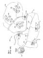
- FIG. 1illustrates a network 100 deploying passive fiber optic lines.
- the network 100can include a central office 101 that connects a number of end subscribers 105 (also called end users 105 herein) in a network.
- the central office 101can additionally connect to a larger network such as the Internet (not shown) and a public switched telephone network (PSTN).
- PSTNpublic switched telephone network
- the network 100can also include fiber distribution hubs (FDHs) 103 having one or more optical splitters (e.g., 1-to-8 splitters, 1-to-16 splitters, or 1-to-32 splitters) that generate a number of individual fibers that may lead to the premises of an end user 105 .
- the various lines of the network 100can be aerial or housed within underground conduits.
- the portion of the network 100 that is closest to central office 101is generally referred to as the F1 region, where F1 is the “feeder fiber” from the central office 101 .
- the portion of the network 100 closest to the end users 105can be referred to as an F2 portion of network 100 .
- the network 100includes a plurality of break-out locations 102 at which branch cables are separated out from the main cable lines. Branch cables are often connected to drop terminals 104 that include connector interfaces for facilitating coupling of the fibers of the branch cables to a plurality of different subscriber locations 105 .
- Splitters used in an FDH 103can accept a feeder cable F1 having a number of fibers and may split those incoming fibers into, for example, 216 to 432 individual distribution fibers that may be associated with a like number of end user locations.
- an optical splitteris provided prepackaged in an optical splitter module housing and provided with a splitter output in pigtails that extend from the module.
- the splitter output pigtailsare typically connectorized with, for example, SC, LC, or LX.5 connectors.
- the optical splitter moduleprovides protective packaging for the optical splitter components in the housing and thus provides for easy handling for otherwise fragile splitter components. This modular approach allows optical splitter modules to be added incrementally to FDHs 103 as required.
- Certain aspects of the disclosurerelate to fiber optic cable systems.
- a fiber distribution systemincludes one or more fiber distribution hubs (FDHs) that provide an interface between the central office and the subscribers.
- FDHsfiber distribution hubs
- Certain aspects of the disclosurerelate to enhanced access and scalability through the use of modular components, such as modular subscriber termination components.
- inventive aspectscan relate to individual features and to combinations of features. It is to be understood that both the forgoing general description and the following detailed description are exemplary and explanatory only and are not restrictive of the broad inventive concepts upon which the embodiments disclosed herein are based.
- FIG. 1shows a passive fiber optic network
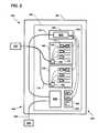
- FIG. 2is a schematic diagram of a cable routing scheme for a fiber distribution hub (FDH);
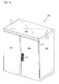
- FIG. 3is a front, perspective view of an exterior of an example FDH cabinet, the cabinet including two doors in the closed position;
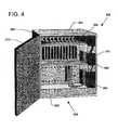
- FIG. 4is a front, perspective view of another example FDH cabinet, the cabinet including one door in the open position revealing a splitter region located at a top of the cabinet, a termination region located beneath the splitter region, and a storage region located beneath the termination region;
- FIG. 5is a front, perspective view of yet another example FDH cabinet, the cabinet including two doors in the open position revealing a splitter region located at a top of the cabinet, three termination regions located beneath the splitter region, and storage regions located on the interior of the doors;
- FIG. 6is a front, perspective view of yet another example FDH cabinet, the cabinet including one door in the open position revealing a splitter region located intermediate multiple termination regions and a storage region located beneath the termination region;
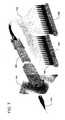
- FIG. 7is a partial, exploded view of an example splitter configured to mount incrementally to an FDH, the splitter having pigtail fibers extending from a boot and terminating at storage modules;
- FIG. 8is a front, perspective view of a housing of a termination module
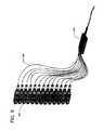
- FIG. 9is a rear, perspective view of twelve connectors configured to be received in the rear of the termination module of FIG. 8 , the connectors having fibers extending from the connectors to a fanout;
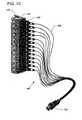
- FIG. 10is a rear, perspective view of the termination module of FIG. 8 coupled to twelve connectors from which fibers extend and terminate at a multi-fiber connector;
- FIG. 11is a rear, perspective view of a swing frame including a splitter region and two termination regions, the swing frame also include shelves extending rearwardly at the splitter and termination regions;
- FIG. 12is a rear view of a bulkhead including a splitter region and a termination region, wherein eight termination modules are installed at the termination region;
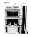
- FIG. 13is a rear view of a swing frame of a FDH, the swing frame including multiple termination modules installed at termination regions on the swing frame.
- a FDH 200includes a cabinet 201 ( FIG. 3 ) that houses internal components.
- the cabinet 201is configured to receive a feeder cable (e.g., or F1 cable) 700 and a subscriber cable 708 (see FIG. 2 ).
- a feeder cablee.g., or F1 cable
- subscriber cable 708see FIG. 2 .
- a swing frame 300( FIG. 2 ) is pivotably mounted (e.g., on hinges) within the cabinet 201 .
- the swing frame 300includes a bulkhead 301 ( FIG. 11 ) that divides the swing frame 300 into a front portion 302 (see FIG. 4 ) and a back portion 304 (see FIG. 11 ).
- the bulkhead 301includes a termination region 340 , a splitter region 350 , and a storage region 360 (see FIG. 2 ). In other embodiments, however, the termination region 340 , splitter region 350 , and storage region 360 can also be fixedly located within the cabinet 201 .
- the bulkhead 301also includes a cable management area 370 (e.g., see FIGS. 4-6 ).
- At least one termination module 400can be installed at the termination region 340
- at least one splitter 500FIG. 7
- at least one storage module 600can be installed at the storage region 360
- One or more feeder cable interfaces 800FIG. 2
- the FDH 200generally administers connections at a termination panel (e.g., the termination region 340 of bulkhead 301 ) between incoming fiber and outgoing fiber in an Outside Plant (OSP) environment.
- a connectionbetween fibers includes both direct and indirect connections.
- incoming fibersinclude the feeder cable fibers 700 that enter the cabinet and intermediate fibers (e.g., connectorized pigtails extending from splitters and patching fibers/jumpers) that connect the feeder cable fibers 700 to the termination panel.
- intermediate fiberse.g., connectorized pigtails extending from splitters and patching fibers/jumpers
- outgoing fibersinclude the subscriber cable fibers 708 that exit the cabinet and any intermediate fibers that connect the subscriber cable fibers 708 to the termination panel.
- the FDH 200provides an interconnect interface for optical transmission signals at a location in the network where operational access and reconfiguration are desired.
- the FDH 200can be used to split the feeder cables and terminate the split feeder cables to distribution cables routed to subscriber locations.
- the FDH 200is designed to accommodate a range of alternative sizes and fiber counts and support factory installation of pigtails, fanouts and splitters.
- a feeder cable 700is initially routed into the FDH 200 through the cabinet 201 (e.g., typically through the back or bottom of the cabinet 201 ).
- the fibers of the feeder cable 700can include ribbon fibers.
- An example feeder cable 700may include twelve to forty-eight individual fibers connected to a service provider central office 101 .
- the fibers of the feeder cable 700are routed to a feeder cable interface 800 (e.g., fiber optic adapter modules, a splice tray, etc.).
- a feeder cable interface 800e.g., fiber optic adapter modules, a splice tray, etc.
- the splitter input fibers 702are routed from the feeder cable interface 800 to the splitter region 350 .
- the splitter input fibers 702are connected to separate splitters 500 , at which the input fibers 702 are each split into multiple pigtails 704 , each having connectorized ends 705 .
- each splitter 500receives between one and four fibers 702 and outputs between two and sixteen fibers 704 for every input fiber 702 .
- the fibers of the feeder cable 700can be connectorized and can be routed directly to the splitters 500 thereby bypassing or eliminating the need for an intermediate feeder cable interface 800 .
- the connectorized ends 705can be temporarily stored on one or more storage modules 600 that are mounted at the storage region 360 .
- the pigtails 704are routed from the splitters 500 to one or more termination modules 400 that are provided at the termination region 340 .
- the termination region 340is the dividing line between incoming fibers and outgoing fibers.
- the pigtails 704are optically coupled to the subscriber cable 708 via adapters 410 .
- a typical distribution cable 708forms the F2 portion of a network (see FIG. 1 ) and typically includes a plurality of fibers (e.g., 144, 216 or 432 fibers) that are routed from the FDH 200 to subscriber locations 105 .
- the fibers of the subscriber cable 708have connectorized ends that can be inserted into the adapters 410 .
- the fibers of the subscriber cable 708are coupled to a cable interface 450 at which the fibers are interfaced with intermediate fibers 706 .
- the intermediate fibers 706extend from the cable interface 450 to fiber connectors 707 configured to be inserted into the rear side of the adapters 410 .
- the intermediate fibers 706can be spliced to the distribution cable 708 .
- one or more of the fibers of the feeder cable 700are not connected to any of the splitters 500 . Rather, these fibers of the feeder cable 700 are connected to pass-through fibers (not shown) having connectorized ends.
- the pass-through fibersare connected to the termination modules 400 , without first connecting to the splitters 500 . By refraining from splitting a fiber, a stronger signal can be sent through the fiber to one of the subscribers.
- the connectorized ends of the pass-through fiberscan be stored at the storage region 360 when not in use.
- the cabinet 201 of a FDH 200generally includes a top panel 202 ( FIG. 3 ), a bottom panel 203 ( FIG. 4 ), a right side panel 204 ( FIG. 3 ), a left side panel 206 ( FIG. 4 ), a back panel (not shown), and at least one front door 210 ( FIG. 4 ).
- the at least one front doorincludes a first door 210 and a second door 212 ( FIG. 3 ).
- the front doors 210 , 212include a lock 211 ( FIG. 3 ).
- the at least one front door 210can be pivotally mounted to the cabinet 201 using hinges 214 , 216 ( FIG. 3 ) to facilitate access to the components mounted within the cabinet 201 .
- the cabinet 201 of the FDH 200is configured to protect the internal components against rain, wind, dust, rodents and other contaminants.
- the cabinet 201remains relatively lightweight for easy installation, and breathable to prevent accumulation of moisture in the unit.
- an aluminum construction with a heavy powder coat finishalso provides for corrosion resistance.
- the cabinet 201is manufactured from heavy gauge aluminum and is NEMA-4X rated. In other embodiments, however, other materials can also be used.
- the FDH 200can be provided in a pole mount or a pedestal mount configuration.
- loops 218can be provided on the cabinet 201 for facilitating deployment of the cabinet 201 at a desired location.
- the loops 218can be used to position the cabinet 201 using a crane.
- the cranecan lower the cabinet 201 into an underground region or vault.
- the loops 218are removable or can be adjusted to not protrude from the top cabinet panel 202 .
- pedestal mount locationscan be found in the utility application Ser. No. 11/513,911, filed Aug. 30, 2006 and titled “Post Mount for a Fiber Distribution Hub,” the disclosure of which is hereby incorporated by reference.
- a swing frame 300 of the FDH 200can be pivotably mounted (e.g., on hinges) within the cabinet 201 .
- the entirety of the swing frame 300including the termination region 340 , the storage region 360 , and the splitter region 350 , can be swung out of the front door 210 of the cabinet 201 to enable access to optical components in the rear portion 304 of the swing frame 300 for cleaning, testing, maintenance, additions, etc.
- Pivoting the swing frame 300 out of the cabinet 201causes one side of the swing frame 300 to move away from the interior volume of the cabinet 201 (not shown).
- the swing frame 300can be pivoted ninety degrees or more out of the cabinet 201 .
- the pivot axis of the swing frame 300is positioned to provide a single point of flex for the fiber cables routed to the swing frame 300 .
- This pivot axisis configured to control the fiber bend.
- the pivot axisis configured to ensure that manufacture recommended bend radii are maintained when the swing frame 300 is opened or closed.
- the cabinet 201can be configured at a factory, or plant, so as to have cable bundles dressed about the pivot axis. Precabling the cabinet 201 reduces the chance that cabling will be done incorrectly.
- the splitter region 350is located at the front and top of the swing frame 300
- the storage region 360is located at the front and bottom of the swing frame 300
- the termination region 340is located intermediate the splitter region 350 and the storage region 360 .
- the splitters 500 located in the splitter region 350are accessible through the open top of the swing frame 300 when the swing frame 300 is swung out of the cabinet 201 .
- storage regions 360 ′can be located on the doors 210 ′, 212 ′ of the FDH 200 ′ instead of on the swing frame 300 (see FIG. 5 ). Positioning the storage regions 360 ′ on the doors 210 , 212 enables a greater number of termination modules 400 to be installed on the bulkhead 301 of the swing frame 300 .
- termination modules 340 ′′can be located both above and beneath the splitter region 350 ′′.
- the swing frame 300includes a release latch (not shown) that locks the swing frame 300 in a closed position within the cabinet 201 of the FDH 200 until the latch is actuated. When the latch is actuated, the swing frame 300 can be pivoted out of the cabinet 201 .
- a pivoting locking member(not shown) can be mounted to the swing frame 300 to hold the swing frame 300 in the open position.
- FIG. 7illustrates an example splitter 500 coupled to two example storage modules 600 .
- Further information regarding the incremental addition of splitter modules 500can be found in the utility application Ser. No. 11/213,772, filed Aug. 30, 2005, and titled “Compact Blind Mateable Optical Splitter,” the disclosure of which is hereby incorporated by reference.
- Further information regarding incremental addition of storage modules 600can be found in U.S. application Ser. No. 10/871,555, filed Jun. 18, 2004, and titled “Multi-Position Fiber Optic Connector Holder;” and U.S. application Ser. No. 11/203,157, filed Aug. 15, 2005, and titled “Hinged Parking in Fiber Distribution Hubs,” the disclosures of which are hereby incorporated by reference.
- This documentwill focus on the incremental addition of termination modules 400 to the swing frame 300 .
- FIGS. 8-10illustrate one example of a termination module 400 .
- the termination module 400includes a body 401 having a front side 402 (see FIG. 8 ) and a rear side 404 (see FIG. 10 ).
- the body 401is configured to hold at least one fiber optic adapter 410 extending from the front side 402 to the rear side 404 .
- the body 401is configured to hold about twelve fiber optic adapters 410 (see FIG. 8 ).
- the adapters 410are arranged in a single row configuration. In other embodiments, the adapters 410 can be arranged in a square pattern or in any other desired configuration.
- each fiber optic adapter 410is configured to receive a connectorized end 705 of a splitter pigtail 704 and the rear 404 is configured to receive a connectorized end 707 of the subscriber cable 708 or an intermediate fiber 706 .
- the adapters 410align and optically couple the connectorized ends 705 , 707 of the fibers.
- the adapters 410are configured to receive SC/APC connectors. In other embodiments, however, the adapters 410 can be configured to receive any desired type of optical connector.
- fibersare routed from the connectors 707 to a fanout 470 ( FIG. 9 ) from which a ribbonized intermediate cable 706 extends. In other embodiments, however, intermediate fibers 706 extend outwardly from the connectors 707 and terminate at a multi-fiber connector 712 ( FIG. 10 ). Examples of multi-fiber connectors are disclosed in U.S. Pat. No. 6,957,920 and U.S. Publication No. 2005/0180702 A1, the disclosures of which are hereby incorporated by reference in their entirety.
- the multi-fiber connector 712can be interfaced with the subscriber cable 708 at an adapter 455 provided at the cable interface 450 ( FIG. 2 ).
- adaptersconfigured to receive multi-fiber connectors are disclosed in U.S. Pat. Nos. 5,867,621 and 6,863,446, the disclosures of which are incorporated by reference.
- the intermediate fibers 706can be spliced to the subscriber cable 708 .
- the FDH 200can be precabled in anticipation of the user installing one or more termination modules 400 .
- one or more adapters 455can be provided at the cable interface 450 to receive the multi-fiber connector (MFC) 712 of each termination module 400 .
- MFC connectors terminating either the subscriber cable 708 or a stub cable 714 interfaced with the distribution cable 708are inserted into the adapters 455 at the factory. Dust plugs (not shown) can be installed on the front end of each adapter 455 until a corresponding termination module 400 is installed.
- one or more termination modules 400can be installed at the termination region 340 of the FDH 200 at the factory before deployment. Termination modules 400 can also be added incrementally after deployment of the FDH 200 .
- the termination modules 400 installed at the factorycan be precabled to hold the connectorized ends 707 of the intermediate fibers 706 .
- the opposite ends of the intermediate fibers 706terminate at the MFC connector 712 which is inserted into an adapter 455 at the cable interface 450 .
- Dust caps 709( FIG. 8 ) are generally provided on the front end 402 of the adapters 410 of the termination module 400 to protect the terminated intermediate fibers 706 from dust, dirt, and other contaminants.
- the termination module 400is not precabled and dust caps 709 are also provided on the rear ends 404 of the adapters 410 to protect the adapters 410 .
- the termination region 340defines at least one opening 342 at which a termination module 400 can be installed.
- the termination region 340includes twelve elongated, rectangular openings 342 .
- Each opening 342is configured to receive a storage module body 401 arranged to retain twelve fiber optic adapters 410 in a row. In other embodiments, however, any desired number of openings 342 can be arranged in any desired configuration.
- the openings 342are sufficiently spaced to provide a surface on the bulkhead 301 , for example, on the front of the bulkhead 301 , for adhering labeling information (e.g., connector designations).
- the front side 402 of the termination module 400mounts to the rear side of the bulkhead 301 of the swing frame 300 .
- the front 402 of the adapters 410protrudes forwardly from the body 401 so that the connectors 705 of the splitter pigtails 704 enter the front ends of the adapters 410 from the front side 302 of the bulkhead 301 and the connectors 707 of the intermediate fibers 706 enter the rear sides 404 of the adapters 410 from the rear side 304 of the bulkhead 301 .
- the body 401is designed to snap into one of the openings 342 defined in the termination region 340 .
- the termination module 400mounts to the bulkhead 301 with one or more latches 430 .
- the termination module 400 shown in FIG. 10includes a latch 430 on one end of the body 401 .
- additional latches 430 or other types of fastenerscan be used.
- Other fastenerssuch as screws, bolts, rivets, nails, and other such devices, can be used in addition or as an alternative to the latches 430 to connect the modules 400 to the bulkhead 301 .
- the swing frame 300an include shelves extending rearwardly from the bulkhead 301 .
- a splitter shelf 355can extend rearwardly from the bulkhead 301 adjacent the splitter region 350 and a termination shelf 345 can extend rearwardly from the bulkhead 301 adjacent the termination region 340 (see FIGS. 11-13 ).
- the swing frame 300includes multiple termination regions (e.g., termination regions 340 of FIG. 11 ). In such embodiments, an equal number of termination shelves 345 extend rearwardly from the bulkhead 301 adjacent the termination regions 340 .
- a termination shelf 345can include at least one cable management device for managing excess fiber length of the subscriber cable 708 or the stub fibers 714 (e.g., see FIG. 13 ).
- the stub fibers 714 or subscriber cable fibers 708are routed in a loop having a minimum bend radius to a fanout or other breakout device 475 ( FIG. 11 ).
- the cable fanout 475joins the fibers into a ribbonized cable.
- Examples of cable management devices that can be used to maintain the loopinclude a fiber spool, one or more radius bend limiters, one or more fiber clips, and other such devices.
- the fiberscan be laid on the shelves in loops without interacting with cable management devices.
- the cable interface 450can include a panel located on a termination shelf 345 .
- the panel 450is configured to hold one or more adapters 455 .
- the panel 450includes an adapter 455 for each opening 342 configured to receive a termination module 400 .
- Each adapter 455is configured to receive and optically couple first and second multi-fiber connectors (MFC).
- MFCmulti-fiber connectors
- the termination shelf 345can be used to store mass splices between the intermediate fibers 706 and the distribution cable 708 .
- FIG. 11illustrates one example FDH 200 including first and second termination regions 340 and shelves 345 extending rearwardly at each of the termination regions 340 .
- Each termination region 340defines rectangular openings 342 , each opening 342 being configured to receive a termination module 400 .
- Seven termination modules 400have been installed in the first termination region 340 located nearest the splitter region 350 . Only one termination module 400 has been installed at the other termination region 340 .
- the fibers 706 of only one termination module 400 for each region 340are illustrated. The fibers 706 extend rearwardly from the termination modules 400 , over the shelf 345 , to the panel 450 .
- ends of stub cables 714are terminated at multi-fiber connectors that are inserted into the opposite ends of the multi-fiber adapters 455 .
- the stub multi-fiber cables 714extend from the panel 450 , over the shelf 345 in a configuration designed to maintain the manufacturer's suggested bend radii, and to a cable management device 475 that groups the cables 714 into one or more buffer tubes.
- the cables 714are routed and optically coupled to the subscriber cable 708 .
- the ribbonized stub cable 714can be spliced to the subscriber distribution cable 708 within or outside the FDH 200 . In various embodiments, the stub cable ranges in length from about 25 feet to about 300 feet.
- the distribution cable 708can be routed into the cabinet 201 and spliced or otherwise connected to the termination module fibers 706 .
- the distribution cable 708can terminate at one or more multi-fiber connectors. As shown at the second termination region 340 of FIG. 11 , these connectors can be inserted into the adapters 455 at the panel 450 and directly interfaced with the termination module fibers 706 .
- the fiber distribution hub 200can be manufactured in a variety of different sizes. However, to promote manufacturing efficiency, it is preferred for the splitters to be manufactured with pigtails having uniform lengths. To accommodate the different sizes of fiber distribution hubs, the pigtails are preferably designed long enough to work in the largest fiber distribution hub expected to be used. For the smaller distribution hubs, excess length provided in the pigtails can be taken up by wrapping the excess length around at fiber storage areas. For example, the excess length can be wrapped around spools 252 , 254 (see FIG. 7 ) provided at the top of the swing frame.
- splitters 500that can be utilized in the FDH 200 described herein can be found in U.S. patent application Ser. No. 11/354,297, filed Feb. 13, 2006, titled “Fiber Optic Splitter Module;” U.S. application Ser. No. 10/980,978, filed Nov. 3, 2004, titled “Fiber Optic Module And System Including Rear Connectors;” U.S. application Ser. No. 11/138,063, filed May 25, 2005, titled “Fiber Optic Splitter Module;” U.S. application Ser. No. 11/215,837, filed Aug. 29, 2005, entitled “Fiber Optic Splitter Module With Connector Access;” and U.S. application Ser. No. 11/321,696, filed Dec. 28, 2005, titled “Splitter Modules For Fiber Distribution Hubs,” the disclosures of which are hereby incorporated by reference.
Landscapes
- Physics & Mathematics (AREA)
- General Physics & Mathematics (AREA)
- Optics & Photonics (AREA)
- Light Guides In General And Applications Therefor (AREA)
Abstract
Description
Claims (12)
Priority Applications (1)
| Application Number | Priority Date | Filing Date | Title |
|---|---|---|---|
| US13/251,680US8498511B2 (en) | 2005-08-30 | 2011-10-03 | Fiber distribution hub with modular termination blocks |
Applications Claiming Priority (4)
| Application Number | Priority Date | Filing Date | Title |
|---|---|---|---|
| US71214705P | 2005-08-30 | 2005-08-30 | |
| US11/513,910US7623749B2 (en) | 2005-08-30 | 2006-08-30 | Fiber distribution hub with modular termination blocks |
| US12/615,672US8068712B2 (en) | 2005-08-30 | 2009-11-10 | Fiber distribution hub |
| US13/251,680US8498511B2 (en) | 2005-08-30 | 2011-10-03 | Fiber distribution hub with modular termination blocks |
Related Parent Applications (1)
| Application Number | Title | Priority Date | Filing Date |
|---|---|---|---|
| US12/615,672ContinuationUS8068712B2 (en) | 2005-08-30 | 2009-11-10 | Fiber distribution hub |
Publications (2)
| Publication Number | Publication Date |
|---|---|
| US20120201503A1 US20120201503A1 (en) | 2012-08-09 |
| US8498511B2true US8498511B2 (en) | 2013-07-30 |
Family
ID=38263256
Family Applications (3)
| Application Number | Title | Priority Date | Filing Date |
|---|---|---|---|
| US11/513,910ActiveUS7623749B2 (en) | 2005-08-30 | 2006-08-30 | Fiber distribution hub with modular termination blocks |
| US12/615,672Expired - Fee RelatedUS8068712B2 (en) | 2005-08-30 | 2009-11-10 | Fiber distribution hub |
| US13/251,680Expired - Fee RelatedUS8498511B2 (en) | 2005-08-30 | 2011-10-03 | Fiber distribution hub with modular termination blocks |
Family Applications Before (2)
| Application Number | Title | Priority Date | Filing Date |
|---|---|---|---|
| US11/513,910ActiveUS7623749B2 (en) | 2005-08-30 | 2006-08-30 | Fiber distribution hub with modular termination blocks |
| US12/615,672Expired - Fee RelatedUS8068712B2 (en) | 2005-08-30 | 2009-11-10 | Fiber distribution hub |
Country Status (1)
| Country | Link |
|---|---|
| US (3) | US7623749B2 (en) |
Cited By (3)
| Publication number | Priority date | Publication date | Assignee | Title |
|---|---|---|---|---|
| US8961035B2 (en) | 2010-08-02 | 2015-02-24 | Adc Telecommunications, Inc. | Architecture for a fiber optic network |
| US9632269B1 (en) | 2015-11-25 | 2017-04-25 | Corning Optical Communications LLC | Systems for stacking modular fiber optic cabinets, and related devices, components, and methods |
| US10935745B1 (en) | 2017-07-20 | 2021-03-02 | Forrest Tyrone Gay | Multi-carrier fiber distribution hub |
Families Citing this family (83)
| Publication number | Priority date | Publication date | Assignee | Title |
|---|---|---|---|---|
| US6760531B1 (en) | 1999-03-01 | 2004-07-06 | Adc Telecommunications, Inc. | Optical fiber distribution frame with outside plant enclosure |
| US7142764B2 (en) | 2003-03-20 | 2006-11-28 | Tyco Electronics Corporation | Optical fiber interconnect cabinets, termination modules and fiber connectivity management for the same |
| US6983095B2 (en) | 2003-11-17 | 2006-01-03 | Fiber Optic Network Solutions Corporation | Systems and methods for managing optical fibers and components within an enclosure in an optical communications network |
| US7369741B2 (en) | 2003-11-17 | 2008-05-06 | Fiber Optics Network Solutions Corp. | Storage adapter with dust cap posts |
| WO2006135524A2 (en)* | 2005-05-18 | 2006-12-21 | Corning Cable Systems Llc | High density optical fiber distribution enclosure |
| US7623749B2 (en) | 2005-08-30 | 2009-11-24 | Adc Telecommunications, Inc. | Fiber distribution hub with modular termination blocks |
| US7760984B2 (en) | 2006-05-04 | 2010-07-20 | Adc Telecommunications, Inc. | Fiber distribution hub with swing frame and wrap-around doors |
| US7711234B2 (en) | 2006-10-02 | 2010-05-04 | Adc Telecommunications, Inc. | Reskinnable fiber distribution hub |
| US7519258B2 (en)* | 2006-12-21 | 2009-04-14 | Corning Cable Systems Llc | Preconnectorized fiber optic local convergence points |
| US7349616B1 (en) | 2007-01-12 | 2008-03-25 | Corning Cable Systems Llc | Fiber optic local convergence points for multiple dwelling units |
| US7400814B1 (en) | 2007-01-13 | 2008-07-15 | Furukawa Electric North America, Inc. | Wall-mountable optical fiber and cable management apparatus |
| US7522805B2 (en)* | 2007-03-09 | 2009-04-21 | Adc Telecommunications, Inc. | Wall mount distribution arrangement |
| US7715679B2 (en) | 2007-05-07 | 2010-05-11 | Adc Telecommunications, Inc. | Fiber optic enclosure with external cable spool |
| US7734138B2 (en)* | 2007-05-30 | 2010-06-08 | Corning Cable Systems Llc | Fiber optic connector holders |
| US7756379B2 (en) | 2007-08-06 | 2010-07-13 | Adc Telecommunications, Inc. | Fiber optic enclosure with internal cable spool |
| US7869682B2 (en) | 2007-09-05 | 2011-01-11 | Adc Telecommunications, Inc. | Fiber optic enclosure with tear-away spool |
| US7751672B2 (en) | 2007-10-31 | 2010-07-06 | Adc Telecommunications, Inc. | Low profile fiber distribution hub |
| US8229265B2 (en)* | 2007-11-21 | 2012-07-24 | Adc Telecommunications, Inc. | Fiber distribution hub with multiple configurations |
| US8238709B2 (en) | 2007-12-18 | 2012-08-07 | Adc Telecommunications, Inc. | Multi-configuration mounting system for fiber distribution hub |
| US7715682B2 (en)* | 2008-03-04 | 2010-05-11 | Adc Telecommunications, Inc. | Fiber distribution hub having an adjustable plate |
| US8059931B2 (en)* | 2008-05-06 | 2011-11-15 | Realm Communications Group, Inc. | Fiber optic monitoring patch panel providing readily accessible monitoring ports |
| US11294136B2 (en) | 2008-08-29 | 2022-04-05 | Corning Optical Communications LLC | High density and bandwidth fiber optic apparatuses and related equipment and methods |
| CN102209921B (en) | 2008-10-09 | 2015-11-25 | 康宁光缆系统有限公司 | There is the fibre-optic terminus supported from the adapter panel of the input and output optical fiber of optical splitters |
| WO2010059623A1 (en) | 2008-11-21 | 2010-05-27 | Adc Telecommunications, Inc. | Fiber optic telecommunications module |
| US8081857B2 (en)* | 2008-12-31 | 2011-12-20 | Opterna Am, Inc. | System for an internal rotating storage spool combined with top and bottom cable access in a fiber distribution terminal |
| US8903215B2 (en) | 2008-12-31 | 2014-12-02 | Opterna Technology Limited | Enclosure-less fiber optic terminals |
| US7899300B2 (en)* | 2009-06-03 | 2011-03-01 | Emerson Network Power, Energy Systems, North America, Inc. | Dust caps for fiber optic connectors |
| US8244089B2 (en)* | 2009-06-03 | 2012-08-14 | Emerson Network Power, Energy Systems, North America, Inc. | Dust caps for fiber optic connectors |
| EP2443497B1 (en)* | 2009-06-19 | 2020-03-04 | Corning Cable Systems LLC | High density and bandwidth fiber optic apparatus |
| ES2403007A1 (en)* | 2009-07-01 | 2013-05-13 | Adc Telecommunications, Inc | Wall-mounted fiber distribution hub |
| KR101820175B1 (en) | 2009-07-21 | 2018-01-18 | 콤스코프 커넥티비티 엘엘씨 | Rapid universal rack mount enclosure |
| CN102870021B (en) | 2010-03-02 | 2015-03-11 | 蒂安电子服务有限责任公司 | Fibre-optic telecommunication module |
| US8649649B2 (en) | 2010-03-03 | 2014-02-11 | Adc Telecommunications, Inc. | Fiber distribution hub with connectorized stub cables |
| US20110235986A1 (en)* | 2010-03-24 | 2011-09-29 | Adc Telecommunications, Inc. | Optical fiber drawer with connectorized stub cable |
| US9078287B2 (en) | 2010-04-14 | 2015-07-07 | Adc Telecommunications, Inc. | Fiber to the antenna |
| US8837940B2 (en) | 2010-04-14 | 2014-09-16 | Adc Telecommunications, Inc. | Methods and systems for distributing fiber optic telecommunication services to local areas and for supporting distributed antenna systems |
| WO2011140461A2 (en) | 2010-05-07 | 2011-11-10 | Adc Telecommunications, Inc. | Fiber distribution hub with pass-through interfaces |
| US9377597B2 (en)* | 2010-06-02 | 2016-06-28 | Commscope Technologies Llc | Aggregator for a switch rack system |
| AU2010355632B2 (en) | 2010-06-18 | 2014-09-18 | Adc Communications (Shanghai) Co., Ltd. | Fiber optic distribution terminal and method of deploying fiber distribution cable |
| CN110174737A (en) | 2010-06-23 | 2019-08-27 | Adc电信公司 | Telecommunication assembly |
| US8472773B2 (en) | 2010-08-06 | 2013-06-25 | Corning Cable Systems Llc | Fiber optic connector holder |
| WO2012054454A2 (en) | 2010-10-19 | 2012-04-26 | Corning Cable Systems Llc | Transition box for multiple dwelling unit fiber optic distribution network |
| WO2012058391A1 (en) | 2010-10-28 | 2012-05-03 | Corning Cable Systems Llc | Impact resistant fiber optic enclosures and related methods |
| CN102565970B (en)* | 2010-12-30 | 2015-05-06 | 鸿富锦精密工业(深圳)有限公司 | Optical fiber concentrator |
| CA2877896C (en)* | 2011-06-24 | 2020-07-21 | Adc Telecommunications, Inc. | Fiber termination enclosure with modular plate assemblies |
| US9417418B2 (en) | 2011-09-12 | 2016-08-16 | Commscope Technologies Llc | Flexible lensed optical interconnect device for signal distribution |
| RU2611105C2 (en) | 2011-10-07 | 2017-02-21 | Адс Телекоммьюникейшнз, Инк. | Fibre-optic cartridge, system and method |
| US9069151B2 (en) | 2011-10-26 | 2015-06-30 | Corning Cable Systems Llc | Composite cable breakout assembly |
| US8886005B2 (en) | 2012-02-13 | 2014-11-11 | Opterna Technology Limited | Adapter retaining systems |
| US8913867B2 (en)* | 2011-11-21 | 2014-12-16 | Opterna Technology Limited | Fiber optic collector and terminal assemblies |
| US9219546B2 (en) | 2011-12-12 | 2015-12-22 | Corning Optical Communications LLC | Extremely high frequency (EHF) distributed antenna systems, and related components and methods |
| US9188760B2 (en) | 2011-12-22 | 2015-11-17 | Adc Telecommunications, Inc. | Mini rapid delivery spool |
| CN104040395B (en) | 2012-01-06 | 2016-06-01 | 惠普发展公司,有限责任合伙企业 | Optics is connected to the connector modules of electronic installation |
| US10110307B2 (en) | 2012-03-02 | 2018-10-23 | Corning Optical Communications LLC | Optical network units (ONUs) for high bandwidth connectivity, and related components and methods |
| US8873926B2 (en) | 2012-04-26 | 2014-10-28 | Corning Cable Systems Llc | Fiber optic enclosures employing clamping assemblies for strain relief of cables, and related assemblies and methods |
| US9004778B2 (en) | 2012-06-29 | 2015-04-14 | Corning Cable Systems Llc | Indexable optical fiber connectors and optical fiber connector arrays |
| WO2014011904A2 (en)* | 2012-07-11 | 2014-01-16 | Adc Telecommunications, Inc. | Telecommunications cabinet modularization |
| US9049500B2 (en) | 2012-08-31 | 2015-06-02 | Corning Cable Systems Llc | Fiber optic terminals, systems, and methods for network service management |
| NZ706687A (en) | 2012-09-28 | 2017-09-29 | Adc Telecommunications Inc | Fiber optic cassette |
| US9146374B2 (en) | 2012-09-28 | 2015-09-29 | Adc Telecommunications, Inc. | Rapid deployment packaging for optical fiber |
| US9223094B2 (en) | 2012-10-05 | 2015-12-29 | Tyco Electronics Nederland Bv | Flexible optical circuit, cassettes, and methods |
| ES1141660Y (en) | 2012-12-19 | 2015-10-14 | Tyco Electronics Raychem Bvba | Distribution device with incrementally added dividers |
| WO2014134154A1 (en)* | 2013-02-26 | 2014-09-04 | Tyco Electronics Corporation | High density splitter aggregation module |
| US9435975B2 (en) | 2013-03-15 | 2016-09-06 | Commscope Technologies Llc | Modular high density telecommunications frame and chassis system |
| WO2015116672A1 (en) | 2014-01-28 | 2015-08-06 | Adc Telecommunications, Inc. | Slidable fiber optic connection module with cable slack management |
| US9494758B2 (en) | 2014-04-03 | 2016-11-15 | Commscope Technologies Llc | Fiber optic distribution system |
| AU2015276109B2 (en) | 2014-06-17 | 2020-11-19 | Adc Czech Republic, S.R.O. | Cable distribution system |
| US10362710B2 (en) | 2014-10-01 | 2019-07-23 | American Products, L.L.C. | Below grade enclosure |
| CN105676380B (en)* | 2014-11-21 | 2019-07-12 | 泰科电子(上海)有限公司 | Cable runs system and multifibre joint |
| US9885845B2 (en)* | 2015-01-15 | 2018-02-06 | Commscope, Inc. Of North Carolina | Module and assembly for fiber optic interconnections |
| US10606009B2 (en)* | 2015-12-01 | 2020-03-31 | CommScope Connectivity Belgium BVBA | Cable distribution system with fan out devices |
| EP3408701B1 (en) | 2016-01-28 | 2023-04-26 | CommScope Connectivity Belgium BVBA | Modular telecommunications enclosure |
| WO2017158447A1 (en)* | 2016-03-15 | 2017-09-21 | 3M Innovative Properties Company | High density distribution frame with an integrated splicing compartment |
| US10295771B2 (en)* | 2016-05-03 | 2019-05-21 | Corning Optical Communications LLC | Telecommunications terminal with removable modules |
| US11409068B2 (en) | 2017-10-02 | 2022-08-09 | Commscope Technologies Llc | Fiber optic circuit and preparation method |
| US10416406B1 (en) | 2018-03-01 | 2019-09-17 | Afl Telecommunications Llc | Communications module housing |
| US10451828B1 (en) | 2018-11-09 | 2019-10-22 | Afl Telecommunications Llc | Communications module housing |
| US12422641B2 (en)* | 2019-07-17 | 2025-09-23 | Connectivity Solutions Direct LLC | Fiber optic splitter modules and systems |
| WO2021071844A1 (en) | 2019-10-07 | 2021-04-15 | Commscope Technologies Llc | Fiber distribution hub including sealed splice module |
| US12339511B2 (en) | 2020-03-31 | 2025-06-24 | Commscope Technologies Llc | Fiber optic cable management systems and methods |
| IT202000009184A1 (en)* | 2020-04-28 | 2021-10-28 | Prysmian Spa | OUTDOOR CABINET FOR TELECOMMUNICATIONS |
| US20230101187A1 (en)* | 2021-09-30 | 2023-03-30 | Corning Research & Development Corporation | High fiber count cable distribution systems, apparatuses, and methods |
| DK181597B1 (en)* | 2022-05-09 | 2024-06-14 | Triarca As | Cabinet |
Citations (150)
| Publication number | Priority date | Publication date | Assignee | Title |
|---|---|---|---|---|
| US4736100A (en) | 1986-07-31 | 1988-04-05 | Amp Incorporated | Optical loop attenuator simulating an optical system |
| US4747020A (en) | 1986-05-16 | 1988-05-24 | Adc Telecommunications, Inc. | Wire distribution apparatus |
| US4792203A (en) | 1985-09-17 | 1988-12-20 | Adc Telecommunications, Inc. | Optical fiber distribution apparatus |
| US4824196A (en) | 1987-05-26 | 1989-04-25 | Minnesota Mining And Manufacturing Company | Optical fiber distribution panel |
| US4861134A (en) | 1988-06-29 | 1989-08-29 | American Telephone And Telegraph Company, At&T Bell Laboratories | Opto-electronic and optical fiber interface arrangement |
| US4900123A (en) | 1988-08-29 | 1990-02-13 | Gte Products Corporation | 1550 nm fiber distribution panel |
| US4948220A (en) | 1988-06-20 | 1990-08-14 | Societe Anonyme De Telecommunications | Module for distributing and connecting optical fibers |
| US4995688A (en) | 1989-07-31 | 1991-02-26 | Adc Telecommunications, Inc. | Optical fiber distribution frame |
| US5023646A (en) | 1985-12-27 | 1991-06-11 | Minolta Camera Kabushiki Kaisha | Automatic focus detection system |
| US5069636A (en) | 1987-07-07 | 1991-12-03 | Raychem Corporation | Terminal block and adapter |
| US5073042A (en) | 1990-06-21 | 1991-12-17 | Amp Incorporated | Coupling bushing for various types of optical fiber connectors |
| US5076688A (en) | 1990-03-23 | 1991-12-31 | Amp Incorporated | Optical simulator with loop-back attenuator having metalized optical fiber |
| US5142598A (en) | 1991-08-28 | 1992-08-25 | Porta Systems Corp. | Fiber optic connector having snap ring adjustment means |
| US5214730A (en) | 1991-05-13 | 1993-05-25 | Nippon Telegraph And Telephone Corporation | Multifiber optical connector plug with low reflection and low insertion loss |
| US5214735A (en) | 1992-04-06 | 1993-05-25 | Adc Telecommunications, Inc. | Fiber optic connector retainer |
| US5233674A (en) | 1991-11-21 | 1993-08-03 | Methode Electronics, Inc. | Fiber optic connector with sliding tab release |
| US5274729A (en) | 1992-07-30 | 1993-12-28 | At&T Bell Laboratories | Universal optical fiber buildout system |
| US5274731A (en) | 1992-12-24 | 1993-12-28 | Adc Telecommunications, Inc. | Optical fiber cabinet |
| US5317663A (en) | 1993-05-20 | 1994-05-31 | Adc Telecommunications, Inc. | One-piece SC adapter |
| US5333221A (en) | 1992-06-30 | 1994-07-26 | The Whitaker Corporation | Universal adapter for optical connectors |
| US5333222A (en) | 1993-05-14 | 1994-07-26 | Molex Incorporated | Adapter for interconnecting optical fiber connectors or the like |
| US5359688A (en) | 1994-03-04 | 1994-10-25 | Siecor Corporation | Metal internal holding clips for fiber optic connector coupling |
| US5367598A (en) | 1993-10-21 | 1994-11-22 | Nec America, Inc. | Interface chassis for fiber optic transport system |
| US5402515A (en) | 1994-03-01 | 1995-03-28 | Minnesota Mining And Manufacturing Company | Fiber distribution frame system, cabinets, trays and fiber optic connector couplings |
| US5408557A (en) | 1994-04-20 | 1995-04-18 | Hsu; Chung-Tang | FC-type optical fiber cable connector's adaptor |
| US5420958A (en) | 1990-05-21 | 1995-05-30 | Minnesota Mining And Manufacturing Company | Optical fiber distribution center |
| US5442726A (en) | 1994-02-22 | 1995-08-15 | Hubbell Incorporated | Optical fiber storage system |
| US5448015A (en) | 1991-12-30 | 1995-09-05 | Societe Anonyme Dite Alcatel Cit | Support and Guide device for cables carrying elcetrical or light signals |
| US5469526A (en) | 1994-01-07 | 1995-11-21 | Porta Systems Corp. | Optical fiber support for printed circuit boards |
| US5497444A (en) | 1994-01-21 | 1996-03-05 | Adc Telecommunications, Inc. | High-density fiber distribution frame |
| US5511144A (en) | 1994-06-13 | 1996-04-23 | Siecor Corporation | Optical distribution frame |
| US5542015A (en) | 1993-04-08 | 1996-07-30 | The Whitaker Corporation | Optical fiber connector latching mechanism |
| US5647043A (en) | 1995-10-12 | 1997-07-08 | Lucent Technologies, Inc. | Unipartite jack receptacle |
| EP0788002A1 (en) | 1996-02-01 | 1997-08-06 | Molex Incorporated | Fiber optic connector receptacle with protective shutter |
| US5708751A (en) | 1996-04-24 | 1998-01-13 | Tii Industries, Inc. | Optical fiber enclosure system |
| US5734776A (en) | 1996-08-28 | 1998-03-31 | Adc Telecommunications, Inc. | Outside plant cross-connect apparatus |
| US5734774A (en) | 1995-11-30 | 1998-03-31 | Lucent Technologies Inc. | Outdoor electronics cabinet |
| US5758003A (en) | 1996-03-15 | 1998-05-26 | Adc Telecommunications, Inc. | High density fiber management |
| US5764844A (en) | 1994-03-21 | 1998-06-09 | N.V. Raychem S.A. | Splice organizing apparatus |
| US5774612A (en) | 1995-08-02 | 1998-06-30 | Molex Incorporated | Adapted for interconnecting optical fiber connectors |
| US5823646A (en) | 1997-09-02 | 1998-10-20 | Siecor Corporation | Door assembly for optical hardware cabinet |
| US5825955A (en) | 1997-02-05 | 1998-10-20 | Molex Incorporated | Fiber optic diversion connector |
| US5867621A (en) | 1997-04-23 | 1999-02-02 | Siecor Corporation | Adapter and guide pin assembly for coupling of fiber optic connectors |
| US5883995A (en) | 1997-05-20 | 1999-03-16 | Adc Telecommunications, Inc. | Fiber connector and adapter |
| US5892870A (en) | 1995-11-16 | 1999-04-06 | Fiber Connections Inc. | Fibre optic cable connector |
| US5930425A (en) | 1998-04-21 | 1999-07-27 | Lucent Technologies Inc. | High density coupling module |
| US5945633A (en) | 1996-05-23 | 1999-08-31 | The Siemon Company | Rack mountable cable distribution enclosure having an angled adapter plate bracket |
| US5956444A (en) | 1997-02-13 | 1999-09-21 | Amphenol Corporation | Radiation absorbing shield for fiber optic systems |
| US5969294A (en) | 1997-12-31 | 1999-10-19 | Siecor Operations, Llc | Fiber optic connector cabinet with rotatably mounted adapter panels |
| EP0975180A1 (en) | 1998-07-24 | 2000-01-26 | Nippon Telegraph and Telephone Corporation | Optical fiber distribution module, optical fiber cord and fiber distribution system |
| US6027252A (en) | 1997-12-19 | 2000-02-22 | The Whitaker Corporation | Simplified fiber optic receptacle |
| US6044193A (en) | 1998-07-10 | 2000-03-28 | Siecor Operations, Llc | Fiber optic interconnection enclosure having a forced air system |
| US6061492A (en) | 1997-04-09 | 2000-05-09 | Siecor Corporation | Apparatus and method for interconnecting fiber cables |
| US6079881A (en) | 1998-04-08 | 2000-06-27 | Molex Incorporated | Fiber optic connector receptacle assembly |
| EP1045267A1 (en) | 1999-04-15 | 2000-10-18 | Lucent Technologies Inc. | Dust cover for protecting optical fiber sleeve housing |
| US6149315A (en) | 1998-09-04 | 2000-11-21 | Lucent Technologies Inc. | Side load resistant buildout |
| US6160946A (en) | 1998-07-27 | 2000-12-12 | Adc Telecommunications, Inc. | Outside plant fiber distribution apparatus and method |
| WO2000075706A2 (en) | 1999-06-03 | 2000-12-14 | Adc Telecommunications, Inc. | Optical fiber distribution frame with connector modules |
| US6188687B1 (en) | 1994-11-30 | 2001-02-13 | Verizon Laboratories Inc. | Broadband switch that manages traffic and method therefor |
| US6208796B1 (en) | 1998-07-21 | 2001-03-27 | Adc Telecommunications, Inc. | Fiber optic module |
| US6227717B1 (en) | 1997-12-16 | 2001-05-08 | The Siemon Company | Dust caps for use with telecommunications adapters and connectors |
| US6236795B1 (en) | 1999-06-07 | 2001-05-22 | E. Walter Rodgers | High-density fiber optic cable distribution frame |
| US6234683B1 (en) | 1999-09-13 | 2001-05-22 | Stratos Lightwave, Inc. | Field repairable hermaphroditic connector |
| US6240229B1 (en) | 1998-12-21 | 2001-05-29 | Molex Incorporated | Connector assembly |
| US6271484B1 (en) | 1997-10-08 | 2001-08-07 | Ishida Co., Ltd. | Weighing apparatus having an automatic filter adjusting capability |
| US6278829B1 (en) | 1999-05-05 | 2001-08-21 | Marconi Communications, Inc. | Optical fiber routing and support apparatus |
| US6347888B1 (en) | 1998-11-23 | 2002-02-19 | Adc Telecommunications, Inc. | Fiber optic adapter, including hybrid connector system |
| US6356697B1 (en) | 1999-05-04 | 2002-03-12 | Sumitomo Electric Lightwave Corp. | Optical fiber cable distribution shelf with pivotably mounted trays |
| US20020034290A1 (en) | 2000-09-15 | 2002-03-21 | Verizon Services Corp. | Methods and apparatus for facilitating the interaction between multiple telephone and computer users |
| US6385381B1 (en) | 1999-09-21 | 2002-05-07 | Lucent Technologies Inc. | Fiber optic interconnection combination closure |
| US6411767B1 (en) | 1999-08-24 | 2002-06-25 | Corning Cable Systems Llc | Optical fiber interconnection closures |
| US6424781B1 (en) | 1999-03-01 | 2002-07-23 | Adc Telecommunications, Inc. | Optical fiber distribution frame with pivoting connector panels |
| US6425694B1 (en) | 2000-09-18 | 2002-07-30 | Molex Incorporated | Fiber optic receptacle with protective shutter |
| US6431762B1 (en) | 1999-04-09 | 2002-08-13 | Seiko Instruments Inc. | Optical connector adapter |
| US6434313B1 (en) | 2000-10-31 | 2002-08-13 | Corning Cable Systems Llc | Fiber optic closure with couplers and splice tray |
| US6453033B1 (en) | 1998-08-24 | 2002-09-17 | Verizon Services Corp. | Automated system and method for subscriber line service control |
| US6452925B1 (en) | 1996-04-18 | 2002-09-17 | Verizon Services Corp. | Universal access multimedia data network |
| US6464402B1 (en) | 1999-07-28 | 2002-10-15 | Fitel Usa Corp. | Optical fiber connector tuning index tool |
| US6480487B1 (en) | 1998-08-24 | 2002-11-12 | Verizon Services Group | Digital loop carrier remote terminal having integrated digital subscriber plug-in line cards for multiplexing of telephone and broadband signals |
| US6483977B2 (en) | 2001-04-12 | 2002-11-19 | Corning Cable Systems Llc | Fiber management frame having movable work platform |
| USD466087S1 (en) | 2001-01-30 | 2002-11-26 | Nexans | Optical fiber connection cabinet |
| US6496640B1 (en) | 1999-12-16 | 2002-12-17 | Corning Cable Systems Llc | Splice closure with removable and pivotable splice trays, and associated methods |
| WO2002103429A2 (en) | 2000-11-20 | 2002-12-27 | Adc Telecommunications, Inc. | Optical fiber distribution frame with outside plant enclosure |
| US6535682B1 (en) | 1999-03-01 | 2003-03-18 | Adc Telecommunications, Inc. | Optical fiber distribution frame with connector modules |
| US6539160B2 (en) | 2000-10-27 | 2003-03-25 | Corning Cable Systems Llc | Optical fiber splicing and connecting assembly with coupler cassette |
| US6539147B1 (en) | 1999-08-12 | 2003-03-25 | Bellsouth Intellectual Property Corporation | Connectorized inside fiber optic drop |
| US6542688B1 (en) | 2000-10-27 | 2003-04-01 | Corning Cable Systems Llc | Optical fiber splicing and connecting assembly |
| US6554485B1 (en) | 2000-09-11 | 2003-04-29 | Corning Cable Systems Llc | Translucent dust cap and associated method for testing the continuity of an optical fiber jumper |
| US6577595B1 (en) | 1999-11-12 | 2003-06-10 | Genuity Inc. | Systems and methods for transporting associated data signals over a network |
| US6591051B2 (en) | 2001-11-16 | 2003-07-08 | Adc Telecommunications, Inc. | Fiber termination block with angled slide |
| US6597670B1 (en) | 1998-01-26 | 2003-07-22 | Verizon Laboratories Inc. | Method and system for distributing subscriber services using wireless bidirectional broadband loops |
| US6614980B1 (en) | 1999-08-12 | 2003-09-02 | Bellsouth Intellectual Property Corporation | Connectorized outside fiber optic drop |
| US6621975B2 (en) | 2001-11-30 | 2003-09-16 | Corning Cable Systems Llc | Distribution terminal for network access point |
| US20030174996A1 (en) | 2002-03-15 | 2003-09-18 | Fiber Optic Network Solutions, Inc. | Optical fiber enclosure system using integrated optical connector and coupler assembly |
| US6625375B1 (en) | 1999-08-12 | 2003-09-23 | Bellsouth Intellectual Property Corporation | Fiber optic interface device |
| US6631237B2 (en) | 2001-03-06 | 2003-10-07 | Adc Telecommunications, Inc. | Termination and splice panel |
| US6654536B2 (en) | 2001-04-12 | 2003-11-25 | Corning Cable Systems Llc | Fiber management frame having connector platform |
| US6661961B1 (en) | 2000-11-01 | 2003-12-09 | Tyco Electronics Corporation | Fiber low profile network interface device |
| US6715719B2 (en) | 2002-03-27 | 2004-04-06 | Adc Telecommunications, Inc. | Coupler for cable trough |
| US20040074852A1 (en) | 2002-10-21 | 2004-04-22 | Knudsen Clinton M. | High density panel with rotating tray |
| US6778752B2 (en) | 2002-05-31 | 2004-08-17 | Corning Cable Systems Llc | Below grade closure for local convergence point |
| US6788786B1 (en) | 2000-09-22 | 2004-09-07 | Adc Telecommunications, Inc. | Multimedia patching box |
| US6788846B2 (en) | 2002-05-01 | 2004-09-07 | Tyco Electronics Corporation | Fiber management apparatus |
| US6792190B2 (en) | 2001-06-01 | 2004-09-14 | Telect, Inc. | High density fiber optic splitter/connector tray system |
| US6792191B1 (en) | 2003-04-22 | 2004-09-14 | Corning Cable Systems Llc | Local convergence cabinet |
| US6815612B2 (en) | 2002-10-18 | 2004-11-09 | Corning Cable Systems Llc | Watertight seal for network interface device |
| US20040228598A1 (en) | 2003-03-20 | 2004-11-18 | Allen Barry W. | Optical fiber interconnect cabinets, termination modules and fiber connectivity management for the same |
| US20040264873A1 (en) | 2003-06-30 | 2004-12-30 | Smith Trevor D. | Fiber optic connector holder and method |
| US20050002633A1 (en) | 2003-07-02 | 2005-01-06 | Solheid James J. | Telecommunications connection cabinet |
| US6845207B2 (en) | 2001-02-12 | 2005-01-18 | Fiber Optic Network Solutions Corp. | Optical fiber enclosure system |
| US6850685B2 (en) | 2002-03-27 | 2005-02-01 | Adc Telecommunications, Inc. | Termination panel with pivoting bulkhead and cable management |
| US6863446B2 (en) | 2002-03-05 | 2005-03-08 | Fci Americas Technology, Inc. | Optical connector adapter with latch inserts |
| US6870734B2 (en) | 2003-05-30 | 2005-03-22 | Adc Telecommunications, Inc. | Fiber containment system |
| US20050129379A1 (en) | 2003-11-17 | 2005-06-16 | Fiber Optic Network Solutions Corporation | Systems and methods for optical fiber distribution and management |
| US6920274B2 (en) | 2003-12-23 | 2005-07-19 | Adc Telecommunications, Inc. | High density optical fiber distribution frame with modules |
| US6925241B2 (en) | 2002-10-11 | 2005-08-02 | 3M Innovative Properties Company | Drawer for the management of optical fibers |
| US20050180702A1 (en) | 2001-04-06 | 2005-08-18 | Tyco Electronics Corporation | Multifiber ferrule |
| US6957920B2 (en) | 2002-06-24 | 2005-10-25 | Corning Cable Systems Llc | Ferrule assembly having highly protruding optical fibers and an associated fabrication method |
| US20050281526A1 (en) | 2004-06-18 | 2005-12-22 | Soutsada Vongseng | Multi-position fiber optic connector holder and method |
| US6980725B1 (en) | 2002-04-30 | 2005-12-27 | Calix Networks, Inc. | Space reuse during technology upgrade in a protection area of an outdoor enclosure |
| US20060003637A1 (en) | 2002-03-16 | 2006-01-05 | Krone Gmbh | Plug for connection strips and method for the production thereof |
| US20060093301A1 (en) | 2004-11-03 | 2006-05-04 | Zimmel Steven C | Fiber optic module and system including rear connectors |
| US7120347B2 (en) | 2004-01-27 | 2006-10-10 | Corning Cable Systems Llc | Multi-port optical connection terminal |
| US20060228086A1 (en) | 2005-03-31 | 2006-10-12 | Matthew Holmberg | Adapter block including connector storage |
| US20060263029A1 (en) | 2005-05-18 | 2006-11-23 | Mudd Ronald L | High density optical fiber distribution enclosure |
| US20060269206A1 (en) | 2005-05-25 | 2006-11-30 | Zimmel Steven C | Fiber optic adapter module |
| US20060269204A1 (en) | 2005-05-25 | 2006-11-30 | Michael Barth | Outside plant fiber distribution enclosure with radial arrangement |
| US20060269205A1 (en) | 2005-05-25 | 2006-11-30 | Zimmel Steven C | Fiber optic splitter module |
| US20060285807A1 (en) | 2005-06-17 | 2006-12-21 | Yu Lu | Compact blind mateable optical splitter |
| US20070031100A1 (en) | 2005-08-04 | 2007-02-08 | Garcia Cesar G | Optical fiber distribution cabinet |
| US20070047896A1 (en) | 2005-08-31 | 2007-03-01 | Scott Kowalczyk | Cabinet including optical bulkhead plate for blown fiber system |
| US20070047893A1 (en) | 2005-08-29 | 2007-03-01 | Anne Kramer | Fiber optic splitter module with connector access |
| US20070047894A1 (en) | 2005-08-29 | 2007-03-01 | Matt Holmberg | Outside plant enclosure with pivoting fiber trays |
| US7245809B1 (en) | 2005-12-28 | 2007-07-17 | Adc Telecommunications, Inc. | Splitter modules for fiber distribution hubs |
| US20070192817A1 (en) | 2006-02-13 | 2007-08-16 | Landry Edward T | Fiber distribution hub with outside accessible grounding terminals |
| US20070189691A1 (en) | 2006-02-13 | 2007-08-16 | Michael Barth | Fiber distribution hub with swing frame and modular termination panels |
| US20080008436A1 (en) | 2003-11-17 | 2008-01-10 | Fiber Optics Network Solutions Corp. | Hinged parking in fiber distribution hubs |
| US20080019641A1 (en) | 2004-11-03 | 2008-01-24 | Elkins Robert B Ii | Pre-connectorized fiber optic distribution cable having overmolded access location |
| US20080031585A1 (en) | 2006-05-04 | 2008-02-07 | Solheid James J | Fiber Distribution Hub with Swing Frame and Wrap-Around Doors |
| US20080042536A1 (en) | 2006-08-21 | 2008-02-21 | Afl Telecommunications Llc. | Strain relief system |
| US7349605B2 (en) | 2005-04-19 | 2008-03-25 | Adc Telecommunications, Inc. | Fiber breakout with radio frequency identification device |
| US7362925B2 (en) | 2001-12-28 | 2008-04-22 | Fujitsu Limited | Control method and control apparatus of optical device |
| US7416349B2 (en) | 2005-07-27 | 2008-08-26 | Adc Telecommunications, Inc. | Fiber optic adapter module |
| US7418181B2 (en) | 2006-02-13 | 2008-08-26 | Adc Telecommunications, Inc. | Fiber optic splitter module |
| US7460759B2 (en) | 2005-08-30 | 2008-12-02 | Adc Telecommunications, Inc. | Post mount for a fiber distribution hub |
| US7489849B2 (en) | 2004-11-03 | 2009-02-10 | Adc Telecommunications, Inc. | Fiber drop terminal |
| US7492575B2 (en) | 2003-02-25 | 2009-02-17 | Adc Gmbh | Slip-over distribution cabinet |
| US7519258B2 (en) | 2006-12-21 | 2009-04-14 | Corning Cable Systems Llc | Preconnectorized fiber optic local convergence points |
| US20090103879A1 (en) | 2007-10-22 | 2009-04-23 | Adc Telecommunications, Inc. | Fiber Distribution Hub |
| US7623749B2 (en) | 2005-08-30 | 2009-11-24 | Adc Telecommunications, Inc. | Fiber distribution hub with modular termination blocks |
Family Cites Families (5)
| Publication number | Priority date | Publication date | Assignee | Title |
|---|---|---|---|---|
| JPS63229409A (en) | 1987-03-18 | 1988-09-26 | Matsushita Electric Ind Co Ltd | Light emitting/light receiving module |
| DE4424277A1 (en)* | 1994-07-09 | 1996-01-11 | Huels Chemische Werke Ag | One-component aqueous coating systems containing a reactive additive component |
| US5705751A (en)* | 1995-06-07 | 1998-01-06 | Setra Systems, Inc. | Magnetic diaphragm pressure transducer with magnetic field shield |
| US6760532B1 (en)* | 2000-01-28 | 2004-07-06 | Ciena Corporation | Optical device having dynamic channel equalization |
| US7751672B2 (en)* | 2007-10-31 | 2010-07-06 | Adc Telecommunications, Inc. | Low profile fiber distribution hub |
- 2006
- 2006-08-30USUS11/513,910patent/US7623749B2/enactiveActive
- 2009
- 2009-11-10USUS12/615,672patent/US8068712B2/ennot_activeExpired - Fee Related
- 2011
- 2011-10-03USUS13/251,680patent/US8498511B2/ennot_activeExpired - Fee Related
Patent Citations (204)
| Publication number | Priority date | Publication date | Assignee | Title |
|---|---|---|---|---|
| US4792203A (en) | 1985-09-17 | 1988-12-20 | Adc Telecommunications, Inc. | Optical fiber distribution apparatus |
| US5023646A (en) | 1985-12-27 | 1991-06-11 | Minolta Camera Kabushiki Kaisha | Automatic focus detection system |
| US4747020A (en) | 1986-05-16 | 1988-05-24 | Adc Telecommunications, Inc. | Wire distribution apparatus |
| US4736100A (en) | 1986-07-31 | 1988-04-05 | Amp Incorporated | Optical loop attenuator simulating an optical system |
| US4824196A (en) | 1987-05-26 | 1989-04-25 | Minnesota Mining And Manufacturing Company | Optical fiber distribution panel |
| US5069636A (en) | 1987-07-07 | 1991-12-03 | Raychem Corporation | Terminal block and adapter |
| US4948220A (en) | 1988-06-20 | 1990-08-14 | Societe Anonyme De Telecommunications | Module for distributing and connecting optical fibers |
| US4861134A (en) | 1988-06-29 | 1989-08-29 | American Telephone And Telegraph Company, At&T Bell Laboratories | Opto-electronic and optical fiber interface arrangement |
| US4900123A (en) | 1988-08-29 | 1990-02-13 | Gte Products Corporation | 1550 nm fiber distribution panel |
| US4995688A (en) | 1989-07-31 | 1991-02-26 | Adc Telecommunications, Inc. | Optical fiber distribution frame |
| USRE34955E (en) | 1989-07-31 | 1995-05-30 | Adc Telecommunications, Inc. | Optical fiber distribution frame |
| USRE37489E1 (en) | 1989-07-31 | 2002-01-01 | Adc Telecommunications, Inc. | Optical fiber distribution frame |
| US5076688A (en) | 1990-03-23 | 1991-12-31 | Amp Incorporated | Optical simulator with loop-back attenuator having metalized optical fiber |
| US5420958A (en) | 1990-05-21 | 1995-05-30 | Minnesota Mining And Manufacturing Company | Optical fiber distribution center |
| US5073042A (en) | 1990-06-21 | 1991-12-17 | Amp Incorporated | Coupling bushing for various types of optical fiber connectors |
| US5214730A (en) | 1991-05-13 | 1993-05-25 | Nippon Telegraph And Telephone Corporation | Multifiber optical connector plug with low reflection and low insertion loss |
| US5142598A (en) | 1991-08-28 | 1992-08-25 | Porta Systems Corp. | Fiber optic connector having snap ring adjustment means |
| US5233674A (en) | 1991-11-21 | 1993-08-03 | Methode Electronics, Inc. | Fiber optic connector with sliding tab release |
| US5448015A (en) | 1991-12-30 | 1995-09-05 | Societe Anonyme Dite Alcatel Cit | Support and Guide device for cables carrying elcetrical or light signals |
| US5214735A (en) | 1992-04-06 | 1993-05-25 | Adc Telecommunications, Inc. | Fiber optic connector retainer |
| US5333221A (en) | 1992-06-30 | 1994-07-26 | The Whitaker Corporation | Universal adapter for optical connectors |
| US5274729A (en) | 1992-07-30 | 1993-12-28 | At&T Bell Laboratories | Universal optical fiber buildout system |
| US5274731A (en) | 1992-12-24 | 1993-12-28 | Adc Telecommunications, Inc. | Optical fiber cabinet |
| US5542015A (en) | 1993-04-08 | 1996-07-30 | The Whitaker Corporation | Optical fiber connector latching mechanism |
| US5333222A (en) | 1993-05-14 | 1994-07-26 | Molex Incorporated | Adapter for interconnecting optical fiber connectors or the like |
| US5317663A (en) | 1993-05-20 | 1994-05-31 | Adc Telecommunications, Inc. | One-piece SC adapter |
| US5367598A (en) | 1993-10-21 | 1994-11-22 | Nec America, Inc. | Interface chassis for fiber optic transport system |
| US5469526A (en) | 1994-01-07 | 1995-11-21 | Porta Systems Corp. | Optical fiber support for printed circuit boards |
| US5497444A (en) | 1994-01-21 | 1996-03-05 | Adc Telecommunications, Inc. | High-density fiber distribution frame |
| EP0871047A1 (en) | 1994-01-21 | 1998-10-14 | Adc Telecommunications, Inc. | High-density fiber distribution frame |
| US5717810A (en) | 1994-01-21 | 1998-02-10 | Adc Telecommunications, Inc. | High-density fiber distribution frame |
| US5442726A (en) | 1994-02-22 | 1995-08-15 | Hubbell Incorporated | Optical fiber storage system |
| US5402515A (en) | 1994-03-01 | 1995-03-28 | Minnesota Mining And Manufacturing Company | Fiber distribution frame system, cabinets, trays and fiber optic connector couplings |
| US5359688A (en) | 1994-03-04 | 1994-10-25 | Siecor Corporation | Metal internal holding clips for fiber optic connector coupling |
| US5764844A (en) | 1994-03-21 | 1998-06-09 | N.V. Raychem S.A. | Splice organizing apparatus |
| US5408557A (en) | 1994-04-20 | 1995-04-18 | Hsu; Chung-Tang | FC-type optical fiber cable connector's adaptor |
| US5511144A (en) | 1994-06-13 | 1996-04-23 | Siecor Corporation | Optical distribution frame |
| US6188687B1 (en) | 1994-11-30 | 2001-02-13 | Verizon Laboratories Inc. | Broadband switch that manages traffic and method therefor |
| US5774612A (en) | 1995-08-02 | 1998-06-30 | Molex Incorporated | Adapted for interconnecting optical fiber connectors |
| US5647043A (en) | 1995-10-12 | 1997-07-08 | Lucent Technologies, Inc. | Unipartite jack receptacle |
| US5892870A (en) | 1995-11-16 | 1999-04-06 | Fiber Connections Inc. | Fibre optic cable connector |
| US5734774A (en) | 1995-11-30 | 1998-03-31 | Lucent Technologies Inc. | Outdoor electronics cabinet |
| EP0788002A1 (en) | 1996-02-01 | 1997-08-06 | Molex Incorporated | Fiber optic connector receptacle with protective shutter |
| US5758003A (en) | 1996-03-15 | 1998-05-26 | Adc Telecommunications, Inc. | High density fiber management |
| US6452925B1 (en) | 1996-04-18 | 2002-09-17 | Verizon Services Corp. | Universal access multimedia data network |
| US5708751A (en) | 1996-04-24 | 1998-01-13 | Tii Industries, Inc. | Optical fiber enclosure system |
| US5945633A (en) | 1996-05-23 | 1999-08-31 | The Siemon Company | Rack mountable cable distribution enclosure having an angled adapter plate bracket |
| US5734776A (en) | 1996-08-28 | 1998-03-31 | Adc Telecommunications, Inc. | Outside plant cross-connect apparatus |
| US5825955A (en) | 1997-02-05 | 1998-10-20 | Molex Incorporated | Fiber optic diversion connector |
| US5956444A (en) | 1997-02-13 | 1999-09-21 | Amphenol Corporation | Radiation absorbing shield for fiber optic systems |
| US6061492A (en) | 1997-04-09 | 2000-05-09 | Siecor Corporation | Apparatus and method for interconnecting fiber cables |
| US5867621A (en) | 1997-04-23 | 1999-02-02 | Siecor Corporation | Adapter and guide pin assembly for coupling of fiber optic connectors |
| US5883995A (en) | 1997-05-20 | 1999-03-16 | Adc Telecommunications, Inc. | Fiber connector and adapter |
| US5823646A (en) | 1997-09-02 | 1998-10-20 | Siecor Corporation | Door assembly for optical hardware cabinet |
| US6271484B1 (en) | 1997-10-08 | 2001-08-07 | Ishida Co., Ltd. | Weighing apparatus having an automatic filter adjusting capability |
| US6227717B1 (en) | 1997-12-16 | 2001-05-08 | The Siemon Company | Dust caps for use with telecommunications adapters and connectors |
| US6027252A (en) | 1997-12-19 | 2000-02-22 | The Whitaker Corporation | Simplified fiber optic receptacle |
| US5969294A (en) | 1997-12-31 | 1999-10-19 | Siecor Operations, Llc | Fiber optic connector cabinet with rotatably mounted adapter panels |
| US6597670B1 (en) | 1998-01-26 | 2003-07-22 | Verizon Laboratories Inc. | Method and system for distributing subscriber services using wireless bidirectional broadband loops |
| US6079881A (en) | 1998-04-08 | 2000-06-27 | Molex Incorporated | Fiber optic connector receptacle assembly |
| US5930425A (en) | 1998-04-21 | 1999-07-27 | Lucent Technologies Inc. | High density coupling module |
| US6044193A (en) | 1998-07-10 | 2000-03-28 | Siecor Operations, Llc | Fiber optic interconnection enclosure having a forced air system |
| US6208796B1 (en) | 1998-07-21 | 2001-03-27 | Adc Telecommunications, Inc. | Fiber optic module |
| EP0975180A1 (en) | 1998-07-24 | 2000-01-26 | Nippon Telegraph and Telephone Corporation | Optical fiber distribution module, optical fiber cord and fiber distribution system |
| US6160946A (en) | 1998-07-27 | 2000-12-12 | Adc Telecommunications, Inc. | Outside plant fiber distribution apparatus and method |
| US6363200B1 (en) | 1998-07-27 | 2002-03-26 | Adc Telecommunications, Inc. | Outside plant fiber distribution apparatus and method |
| US6480487B1 (en) | 1998-08-24 | 2002-11-12 | Verizon Services Group | Digital loop carrier remote terminal having integrated digital subscriber plug-in line cards for multiplexing of telephone and broadband signals |
| US6453033B1 (en) | 1998-08-24 | 2002-09-17 | Verizon Services Corp. | Automated system and method for subscriber line service control |
| US6149315A (en) | 1998-09-04 | 2000-11-21 | Lucent Technologies Inc. | Side load resistant buildout |
| US6347888B1 (en) | 1998-11-23 | 2002-02-19 | Adc Telecommunications, Inc. | Fiber optic adapter, including hybrid connector system |
| US6240229B1 (en) | 1998-12-21 | 2001-05-29 | Molex Incorporated | Connector assembly |
| US6760531B1 (en) | 1999-03-01 | 2004-07-06 | Adc Telecommunications, Inc. | Optical fiber distribution frame with outside plant enclosure |
| US7139461B2 (en) | 1999-03-01 | 2006-11-21 | Adc Telecommunications, Inc. | Optical fiber distribution frame with outside plant enclosure |
| US7149398B2 (en) | 1999-03-01 | 2006-12-12 | Adc Telecommunications, Inc. | Optical fiber distribution frame with outside plant enclosure |
| US7333707B2 (en) | 1999-03-01 | 2008-02-19 | Adc Telecommunications, Inc. | Optical fiber distribution frame with outside plant enclosure |
| US6556763B1 (en) | 1999-03-01 | 2003-04-29 | Adc Telecommunications, Inc. | Optical fiber distribution frame with connector modules |
| US6535682B1 (en) | 1999-03-01 | 2003-03-18 | Adc Telecommunications, Inc. | Optical fiber distribution frame with connector modules |
| US6424781B1 (en) | 1999-03-01 | 2002-07-23 | Adc Telecommunications, Inc. | Optical fiber distribution frame with pivoting connector panels |
| US20090022467A1 (en) | 1999-03-01 | 2009-01-22 | Adc Telecommunications, Inc. | Optical fiber distribution frame with outside plant enclosure |
| US6431762B1 (en) | 1999-04-09 | 2002-08-13 | Seiko Instruments Inc. | Optical connector adapter |
| US6188825B1 (en) | 1999-04-15 | 2001-02-13 | Lucent Technologies, Inc. | Dust cover for protecting optical fiber sleeve housing |
| EP1045267A1 (en) | 1999-04-15 | 2000-10-18 | Lucent Technologies Inc. | Dust cover for protecting optical fiber sleeve housing |
| US6356697B1 (en) | 1999-05-04 | 2002-03-12 | Sumitomo Electric Lightwave Corp. | Optical fiber cable distribution shelf with pivotably mounted trays |
| US6278829B1 (en) | 1999-05-05 | 2001-08-21 | Marconi Communications, Inc. | Optical fiber routing and support apparatus |
| WO2000075706A2 (en) | 1999-06-03 | 2000-12-14 | Adc Telecommunications, Inc. | Optical fiber distribution frame with connector modules |
| US6236795B1 (en) | 1999-06-07 | 2001-05-22 | E. Walter Rodgers | High-density fiber optic cable distribution frame |
| US6464402B1 (en) | 1999-07-28 | 2002-10-15 | Fitel Usa Corp. | Optical fiber connector tuning index tool |
| US6668127B1 (en) | 1999-08-12 | 2003-12-23 | Bellsouth Intellectual Property Corporation | Connectorized inside fiber optic drop |
| US6625375B1 (en) | 1999-08-12 | 2003-09-23 | Bellsouth Intellectual Property Corporation | Fiber optic interface device |
| US6539147B1 (en) | 1999-08-12 | 2003-03-25 | Bellsouth Intellectual Property Corporation | Connectorized inside fiber optic drop |
| US6614980B1 (en) | 1999-08-12 | 2003-09-02 | Bellsouth Intellectual Property Corporation | Connectorized outside fiber optic drop |
| US6411767B1 (en) | 1999-08-24 | 2002-06-25 | Corning Cable Systems Llc | Optical fiber interconnection closures |
| US6234683B1 (en) | 1999-09-13 | 2001-05-22 | Stratos Lightwave, Inc. | Field repairable hermaphroditic connector |
| US6385381B1 (en) | 1999-09-21 | 2002-05-07 | Lucent Technologies Inc. | Fiber optic interconnection combination closure |
| US6577595B1 (en) | 1999-11-12 | 2003-06-10 | Genuity Inc. | Systems and methods for transporting associated data signals over a network |
| US6496640B1 (en) | 1999-12-16 | 2002-12-17 | Corning Cable Systems Llc | Splice closure with removable and pivotable splice trays, and associated methods |
| US6554485B1 (en) | 2000-09-11 | 2003-04-29 | Corning Cable Systems Llc | Translucent dust cap and associated method for testing the continuity of an optical fiber jumper |
| US20020034290A1 (en) | 2000-09-15 | 2002-03-21 | Verizon Services Corp. | Methods and apparatus for facilitating the interaction between multiple telephone and computer users |
| US6920213B2 (en) | 2000-09-15 | 2005-07-19 | Verizon Services Corp. | Methods and apparatus for facilitating the interaction between multiple telephone and computer users |
| US6425694B1 (en) | 2000-09-18 | 2002-07-30 | Molex Incorporated | Fiber optic receptacle with protective shutter |
| US6788786B1 (en) | 2000-09-22 | 2004-09-07 | Adc Telecommunications, Inc. | Multimedia patching box |
| US6542688B1 (en) | 2000-10-27 | 2003-04-01 | Corning Cable Systems Llc | Optical fiber splicing and connecting assembly |
| US6539160B2 (en) | 2000-10-27 | 2003-03-25 | Corning Cable Systems Llc | Optical fiber splicing and connecting assembly with coupler cassette |
| US6434313B1 (en) | 2000-10-31 | 2002-08-13 | Corning Cable Systems Llc | Fiber optic closure with couplers and splice tray |
| US6661961B1 (en) | 2000-11-01 | 2003-12-09 | Tyco Electronics Corporation | Fiber low profile network interface device |
| WO2002103429A2 (en) | 2000-11-20 | 2002-12-27 | Adc Telecommunications, Inc. | Optical fiber distribution frame with outside plant enclosure |
| USD466087S1 (en) | 2001-01-30 | 2002-11-26 | Nexans | Optical fiber connection cabinet |
| US7068907B2 (en) | 2001-02-12 | 2006-06-27 | Fiber Optic Network Solutions, Corp. | Optical fiber enclosure system |
| US6845207B2 (en) | 2001-02-12 | 2005-01-18 | Fiber Optic Network Solutions Corp. | Optical fiber enclosure system |
| US6631237B2 (en) | 2001-03-06 | 2003-10-07 | Adc Telecommunications, Inc. | Termination and splice panel |
| US20050180702A1 (en) | 2001-04-06 | 2005-08-18 | Tyco Electronics Corporation | Multifiber ferrule |
| US6483977B2 (en) | 2001-04-12 | 2002-11-19 | Corning Cable Systems Llc | Fiber management frame having movable work platform |
| US6654536B2 (en) | 2001-04-12 | 2003-11-25 | Corning Cable Systems Llc | Fiber management frame having connector platform |
| US6792190B2 (en) | 2001-06-01 | 2004-09-14 | Telect, Inc. | High density fiber optic splitter/connector tray system |
| US6591051B2 (en) | 2001-11-16 | 2003-07-08 | Adc Telecommunications, Inc. | Fiber termination block with angled slide |
| US6621975B2 (en) | 2001-11-30 | 2003-09-16 | Corning Cable Systems Llc | Distribution terminal for network access point |
| US7362925B2 (en) | 2001-12-28 | 2008-04-22 | Fujitsu Limited | Control method and control apparatus of optical device |
| US6863446B2 (en) | 2002-03-05 | 2005-03-08 | Fci Americas Technology, Inc. | Optical connector adapter with latch inserts |
| US20030174996A1 (en) | 2002-03-15 | 2003-09-18 | Fiber Optic Network Solutions, Inc. | Optical fiber enclosure system using integrated optical connector and coupler assembly |
| US6909833B2 (en) | 2002-03-15 | 2005-06-21 | Fiber Optic Network Solutions, Inc. | Optical fiber enclosure system using integrated optical connector and coupler assembly |
| US7419384B2 (en) | 2002-03-16 | 2008-09-02 | Adc Gmbh | Plug for connection strips and method for the production thereof |
| US20060003637A1 (en) | 2002-03-16 | 2006-01-05 | Krone Gmbh | Plug for connection strips and method for the production thereof |
| US6850685B2 (en) | 2002-03-27 | 2005-02-01 | Adc Telecommunications, Inc. | Termination panel with pivoting bulkhead and cable management |
| US6715719B2 (en) | 2002-03-27 | 2004-04-06 | Adc Telecommunications, Inc. | Coupler for cable trough |
| US6980725B1 (en) | 2002-04-30 | 2005-12-27 | Calix Networks, Inc. | Space reuse during technology upgrade in a protection area of an outdoor enclosure |
| US6788846B2 (en) | 2002-05-01 | 2004-09-07 | Tyco Electronics Corporation | Fiber management apparatus |
| US6778752B2 (en) | 2002-05-31 | 2004-08-17 | Corning Cable Systems Llc | Below grade closure for local convergence point |
| US6957920B2 (en) | 2002-06-24 | 2005-10-25 | Corning Cable Systems Llc | Ferrule assembly having highly protruding optical fibers and an associated fabrication method |
| US6925241B2 (en) | 2002-10-11 | 2005-08-02 | 3M Innovative Properties Company | Drawer for the management of optical fibers |
| US6815612B2 (en) | 2002-10-18 | 2004-11-09 | Corning Cable Systems Llc | Watertight seal for network interface device |
| US20040074852A1 (en) | 2002-10-21 | 2004-04-22 | Knudsen Clinton M. | High density panel with rotating tray |
| US7086539B2 (en) | 2002-10-21 | 2006-08-08 | Adc Telecommunications, Inc. | High density panel with rotating tray |
| US7492575B2 (en) | 2003-02-25 | 2009-02-17 | Adc Gmbh | Slip-over distribution cabinet |
| US7298952B2 (en) | 2003-03-20 | 2007-11-20 | Tyco Electronics Corporation | Optical fiber interconnect cabinets, termination modules and fiber connectivity management for the same |
| US20040228598A1 (en) | 2003-03-20 | 2004-11-18 | Allen Barry W. | Optical fiber interconnect cabinets, termination modules and fiber connectivity management for the same |
| US7142764B2 (en) | 2003-03-20 | 2006-11-28 | Tyco Electronics Corporation | Optical fiber interconnect cabinets, termination modules and fiber connectivity management for the same |
| US6792191B1 (en) | 2003-04-22 | 2004-09-14 | Corning Cable Systems Llc | Local convergence cabinet |
| US6870734B2 (en) | 2003-05-30 | 2005-03-22 | Adc Telecommunications, Inc. | Fiber containment system |
| US7407330B2 (en) | 2003-06-30 | 2008-08-05 | Adc Telecommunications, Inc. | Fiber optic connector holder and method |
| US20040264873A1 (en) | 2003-06-30 | 2004-12-30 | Smith Trevor D. | Fiber optic connector holder and method |
| US20090087157A1 (en) | 2003-06-30 | 2009-04-02 | Adc Telecommunications, Inc. | Fiber optic connector holder and method |
| US7198409B2 (en) | 2003-06-30 | 2007-04-03 | Adc Telecommunications, Inc. | Fiber optic connector holder and method |
| US7457503B2 (en) | 2003-07-02 | 2008-11-25 | Adc Telecommunications, Inc. | Telecommunications connection cabinet |
| US20050002633A1 (en) | 2003-07-02 | 2005-01-06 | Solheid James J. | Telecommunications connection cabinet |
| US20090074372A1 (en) | 2003-07-02 | 2009-03-19 | Adc Telecommunications, Inc. | Telecommunications connection cabinet |
| US7233731B2 (en) | 2003-07-02 | 2007-06-19 | Adc Telecommunications, Inc. | Telecommunications connection cabinet |
| US7200317B2 (en) | 2003-11-17 | 2007-04-03 | Fiber Optic Network Solutions Corporation | Systems and methods for optical fiber distribution and management |
| US20080008436A1 (en) | 2003-11-17 | 2008-01-10 | Fiber Optics Network Solutions Corp. | Hinged parking in fiber distribution hubs |
| US7471869B2 (en) | 2003-11-17 | 2008-12-30 | Fiber Optics Network Solutions Corp. | Equipment layout for fiber distribution hubs |
| US7646958B1 (en) | 2003-11-17 | 2010-01-12 | Adc Telecommunications, Inc. | Fiber distribution hub with half-loop pigtail storage |
| US7171102B2 (en) | 2003-11-17 | 2007-01-30 | Fiber Optic Network Solutions Corporation | Optical communication signal distribution enclosure |
| US7369741B2 (en) | 2003-11-17 | 2008-05-06 | Fiber Optics Network Solutions Corp. | Storage adapter with dust cap posts |
| US7103255B2 (en) | 2003-11-17 | 2006-09-05 | Fiber Optic Networks Solutions Corporation | Optical splitter module |
| US6983095B2 (en) | 2003-11-17 | 2006-01-03 | Fiber Optic Network Solutions Corporation | Systems and methods for managing optical fibers and components within an enclosure in an optical communications network |
| US7146089B2 (en) | 2003-11-17 | 2006-12-05 | Fiber Optic Network Solutions Corporation | Systems and methods for fiber distribution hub administration |
| US20050129379A1 (en) | 2003-11-17 | 2005-06-16 | Fiber Optic Network Solutions Corporation | Systems and methods for optical fiber distribution and management |
| US7088899B2 (en) | 2003-11-17 | 2006-08-08 | Fiber Optic Networks Solutions Corporation | Configuring pigtails in a fiber distribution hub |
| US7400816B2 (en) | 2003-11-17 | 2008-07-15 | Fiber Optics Network Solutions Corp. | Telecommunications apparatus for distributing optical communications signals |
| US6920274B2 (en) | 2003-12-23 | 2005-07-19 | Adc Telecommunications, Inc. | High density optical fiber distribution frame with modules |
| US20110317973A1 (en)* | 2003-12-23 | 2011-12-29 | Adc Telecommunications, Inc. | Fiber optic termination system |
| US7120347B2 (en) | 2004-01-27 | 2006-10-10 | Corning Cable Systems Llc | Multi-port optical connection terminal |
| US20090190896A1 (en) | 2004-06-18 | 2009-07-30 | Adc Telecommunications, Inc. | Telecommunications cabinet with connector storage |
| US20080317425A1 (en) | 2004-06-18 | 2008-12-25 | Adc Telecommunications, Inc. | Telecommunications cabinet with connector storage |
| US7277620B2 (en) | 2004-06-18 | 2007-10-02 | Adc Telecommunications, Inc. | Fiber optic splitter |
| US20060177190A1 (en) | 2004-06-18 | 2006-08-10 | Adc Telecommunications, Inc. | Fiber optic splitter |
| US7218827B2 (en) | 2004-06-18 | 2007-05-15 | Adc Telecommunications, Inc. | Multi-position fiber optic connector holder and method |
| US20050281526A1 (en) | 2004-06-18 | 2005-12-22 | Soutsada Vongseng | Multi-position fiber optic connector holder and method |
| US7515805B2 (en) | 2004-06-18 | 2009-04-07 | Adc Telecommunications, Inc. | Fiber optic splitter |
| US7519259B2 (en) | 2004-06-18 | 2009-04-14 | Adc Telecommunications, Inc. | Increasing capacity of a telecommunications cabinet |
| US20090196565A1 (en) | 2004-06-18 | 2009-08-06 | Adc Telecommunications, Inc. | Telecommunications Connection Cabinet |
| US7376322B2 (en) | 2004-11-03 | 2008-05-20 | Adc Telecommunications, Inc. | Fiber optic module and system including rear connectors |
| US20080019641A1 (en) | 2004-11-03 | 2008-01-24 | Elkins Robert B Ii | Pre-connectorized fiber optic distribution cable having overmolded access location |
| US7489849B2 (en) | 2004-11-03 | 2009-02-10 | Adc Telecommunications, Inc. | Fiber drop terminal |
| US20060093301A1 (en) | 2004-11-03 | 2006-05-04 | Zimmel Steven C | Fiber optic module and system including rear connectors |
| US7194181B2 (en) | 2005-03-31 | 2007-03-20 | Adc Telecommunications, Inc. | Adapter block including connector storage |
| US20060228086A1 (en) | 2005-03-31 | 2006-10-12 | Matthew Holmberg | Adapter block including connector storage |
| US7349605B2 (en) | 2005-04-19 | 2008-03-25 | Adc Telecommunications, Inc. | Fiber breakout with radio frequency identification device |
| US20060263029A1 (en) | 2005-05-18 | 2006-11-23 | Mudd Ronald L | High density optical fiber distribution enclosure |
| US20060269204A1 (en) | 2005-05-25 | 2006-11-30 | Michael Barth | Outside plant fiber distribution enclosure with radial arrangement |
| US7376323B2 (en) | 2005-05-25 | 2008-05-20 | Adc Telecommunications, Inc. | Fiber optic adapter module |
| US20060269205A1 (en) | 2005-05-25 | 2006-11-30 | Zimmel Steven C | Fiber optic splitter module |
| US7400813B2 (en) | 2005-05-25 | 2008-07-15 | Adc Telecommunications, Inc. | Fiber optic splitter module |
| US20060269206A1 (en) | 2005-05-25 | 2006-11-30 | Zimmel Steven C | Fiber optic adapter module |
| US20060285807A1 (en) | 2005-06-17 | 2006-12-21 | Yu Lu | Compact blind mateable optical splitter |
| US7636507B2 (en) | 2005-06-17 | 2009-12-22 | Adc Telecommunications, Inc. | Compact blind mateable optical splitter |
| US7416349B2 (en) | 2005-07-27 | 2008-08-26 | Adc Telecommunications, Inc. | Fiber optic adapter module |
| US20070031100A1 (en) | 2005-08-04 | 2007-02-08 | Garcia Cesar G | Optical fiber distribution cabinet |
| US20070047893A1 (en) | 2005-08-29 | 2007-03-01 | Anne Kramer | Fiber optic splitter module with connector access |
| US7346254B2 (en) | 2005-08-29 | 2008-03-18 | Adc Telecommunications, Inc. | Fiber optic splitter module with connector access |
| US20070047894A1 (en) | 2005-08-29 | 2007-03-01 | Matt Holmberg | Outside plant enclosure with pivoting fiber trays |
| US7460759B2 (en) | 2005-08-30 | 2008-12-02 | Adc Telecommunications, Inc. | Post mount for a fiber distribution hub |
| US8068712B2 (en) | 2005-08-30 | 2011-11-29 | Adc Telecommunications, Inc. | Fiber distribution hub |
| US7623749B2 (en) | 2005-08-30 | 2009-11-24 | Adc Telecommunications, Inc. | Fiber distribution hub with modular termination blocks |
| US20070047896A1 (en) | 2005-08-31 | 2007-03-01 | Scott Kowalczyk | Cabinet including optical bulkhead plate for blown fiber system |
| US7245809B1 (en) | 2005-12-28 | 2007-07-17 | Adc Telecommunications, Inc. | Splitter modules for fiber distribution hubs |
| US20070189691A1 (en) | 2006-02-13 | 2007-08-16 | Michael Barth | Fiber distribution hub with swing frame and modular termination panels |
| US20070192817A1 (en) | 2006-02-13 | 2007-08-16 | Landry Edward T | Fiber distribution hub with outside accessible grounding terminals |
| US7816602B2 (en) | 2006-02-13 | 2010-10-19 | Adc Telecommunications, Inc. | Fiber distribution hub with outside accessible grounding terminals |
| US7418181B2 (en) | 2006-02-13 | 2008-08-26 | Adc Telecommunications, Inc. | Fiber optic splitter module |
| US20080031585A1 (en) | 2006-05-04 | 2008-02-07 | Solheid James J | Fiber Distribution Hub with Swing Frame and Wrap-Around Doors |
| US20080042535A1 (en) | 2006-08-21 | 2008-02-21 | Afl Telecommunications Llc. | Novel design for a fiber distribution cabinet |
| US20080042536A1 (en) | 2006-08-21 | 2008-02-21 | Afl Telecommunications Llc. | Strain relief system |
| US7519258B2 (en) | 2006-12-21 | 2009-04-14 | Corning Cable Systems Llc | Preconnectorized fiber optic local convergence points |
| US20090103879A1 (en) | 2007-10-22 | 2009-04-23 | Adc Telecommunications, Inc. | Fiber Distribution Hub |
Non-Patent Citations (34)
| Title |
|---|
| 2RU 32 Circuit FMT Review and General FMT Program Update for Cisco, a power point presentation by ADC Telecommunications, Inc., dated Aug. 18, 2005 (12 pages). |
| ADC FONS Outdoor Distribution Enclosure (ODE-13) Installation Instructions, Issue 1, 20 pages (Jun. 2006). |
| ADC Telecommunications, Inc., Fiber Breakout Bay Cable Assembly Installation Guide, ADCP-90-331, Issue 1, Sep. 2002 (18 pages). |
| ADC Telecommunications, Inc., Fiber Breakout Bay Cable Routing Guide, ADCP-90-329, Issue 1, May 2002 (8 pages). |
| ADC Telecommunications, Inc., FL2000 System, pp. 45-60 (© 2000). |
| ADC Telecommunications, Inc.'s 2nd Edition of Fiber Panel Products; front cover, Table of Contents, pp. 1-111, and back cover; revised Jul. 1996, Item No. 846. |
| ADC Telecommunications, Inc.'s 6th Edition of Next Generation Frame (NGF) Product Family Ordering Guide; front cover, Table of Contents, pp. 1-41, and back cover; revised Feb. 2003, Item No. 820. |
| ADC Telecommunications, Inc.'s Fiber Optic, Cable Assemblies and Accessories Brochure; front cover, Table of Contents, pp. 1-23, and back cover; revised Apr. 2003, Item No. 100300. |
| ADC Telecommunications, Inc.'s OMX(TM) 600, Optical Distribution Frame Brochure; front cover, Table of Contents, pp. 1-14, and back cover; revised Feb. 2000, Item No. 854. |
| ADC Telecommunications, Inc.'s OMX™ 600, Optical Distribution Frame Brochure; front cover, Table of Contents, pp. 1-14, and back cover; revised Feb. 2000, Item No. 854. |
| ADC Telecommunications, Inc.'s Outside Plant, Fiber Cross-Connect Solutions Products Brochure; front cover, Table of Contents, pp. 1-48, and back cover; revised Jun. 2002, Item No. 1047. |
| ADC Telecommunications, Inc.'s Secure Fiber Entrance Terminal (SFET) Brochure; front cover, pp. 2-7, and back cover; revised May 1998, Item No. 1005. |
| AMP Inc. catalog entitled "Fiber Optic Products," front and back covers and p. 59 (4 pgs.) (© 1991). |
| AT&T Network Systems catalog entitled "Fiber Optic Products Innovation for wide ranging applications," front and back covers and pp. 6-1 through 6-16 (18 pages) (© 1995). |
| Brochure from Amphenol Corp. entitled "Amphenol® 954 Series one piece SC Connector," 2 pgs. (1990). |
| Catalogue for Fiber Connections, Inc., Gator Patch(TM), 2 pages, May 2003. |
| Catalogue for Fiber Connections, Inc., Gator Patch™, 2 pages, May 2003. |
| DX Breakout Bay Concept 2, a power point presentation by ADC Telecommunications, Inc., (Applicants admit the presentation as prior art as of Jan. 16, 2002) (7 pages). |
| FONS Corporation's MDC Series Rack or Wall Mount Enclosures product sheet, 3 pages, (2002). |
| FONS Corporation's Modular Distribution Cabinets Rack Mount Enclosures, Model MDC-7, product sheet, 2 pages (2005) (shows the same device as shown in Exhibit U). |
| FONS Corporation's Technical Drawing No. 11669, Rev. D, of Distribution Cabinet Assembly MFDC-7, 1 page (technical drawing depicting the device shown in Exhibit V). |
| HRS catalog entitled "Optical Fibre Connectors," front and back covers and pp. 16, 17 and 49 (5 pages) (Mar. 1991). |
| Iwano, S. et al., "MU-type Optical Fiber Connector System," NTT Review, vol. 9, No. 2, pp. 63-71 (Mar. 1997). |
| Nortel Networks OPTera Connect DX-ADC Fiber Breakout Bay, a power point presentation by ADC Telecommunications, Inc., dated Jan. 16, 2002 (10 pages). |
| NTT Int'l Fiber Termination Module (FTM) & Premises Optical Distribution Cabinets (PODC) product brochure, 3 pages (Applicants admit as prior art as of the filing date). |
| Photograph showing a rear, isometric view of the FL2000 panel of Exhibit E, 1 page (Applicants admit the photograph as prior art as of Mar. 20, 2002). |
| Sugita, E. et al., "SC-Type Single-Mode Optical Fiber Connectors," Journal of Lightwave Technology, vol. 7, No. 11, pp. 1689-1696 (Nov. 1989). |
| Technical Drawing having identification No. 1180521, FL2 48 Position MTP Adapter BRKT, showing one example bracket suitable for mounting to the FL2000 panel of Exhibit E, 1 page, dated Mar. 20, 2002. |
| Technical Drawings having identification No. 1254181, DRW-Cisco Patch Panel Specification, showing various views of a patch panel drawer and system, 8 pages (Jul. 25, 2003). |
| U.S. Appl. No. 11/699,716, filed Jan. 29, 2007. |
| U.S. Appl. No. 12/426,723, filed Apr. 20, 2009 entitled "Parking in Fiber Distribution Hubs" inventors: Reagan et al. |
| U.S. Appl. No. 12/435,170, filed May 4, 2009 entitled "Fiber Distribution Hub" inventors: Reagan et al. |
| U.S. Appl. No. 12/435,181, filed May 4, 2009 entitled "Fiber Distribution Device" inventors: Reagan et al. |
| U.S. Appl. No. 12/603,412, filed Oct. 21, 2009 entitled "Fiber Distribution Hubs With Swing Frame Chassis" inventors: Reagan et al. |
Cited By (6)
| Publication number | Priority date | Publication date | Assignee | Title |
|---|---|---|---|---|
| US8961035B2 (en) | 2010-08-02 | 2015-02-24 | Adc Telecommunications, Inc. | Architecture for a fiber optic network |
| US9348097B2 (en) | 2010-08-02 | 2016-05-24 | Commscope Technologies Llc | Architecture for a fiber optic network |
| US10495825B2 (en) | 2010-08-02 | 2019-12-03 | Commscope Technologies Llc | Architecture for a fiber optic network |
| US10830965B2 (en) | 2010-08-02 | 2020-11-10 | Commscope Technologies Llc | Architecture for a fiber optic network |
| US9632269B1 (en) | 2015-11-25 | 2017-04-25 | Corning Optical Communications LLC | Systems for stacking modular fiber optic cabinets, and related devices, components, and methods |
| US10935745B1 (en) | 2017-07-20 | 2021-03-02 | Forrest Tyrone Gay | Multi-carrier fiber distribution hub |
Also Published As
| Publication number | Publication date |
|---|---|
| US7623749B2 (en) | 2009-11-24 |
| US20070165995A1 (en) | 2007-07-19 |
| US20120201503A1 (en) | 2012-08-09 |
| US20100172622A1 (en) | 2010-07-08 |
| US8068712B2 (en) | 2011-11-29 |
Similar Documents
| Publication | Publication Date | Title |
|---|---|---|
| US8498511B2 (en) | Fiber distribution hub with modular termination blocks | |
| US10845560B2 (en) | Fiber distribution hub with swing frame and wrap-around doors | |
| US8380036B2 (en) | Splitter module with connectorized pigtail manager | |
| US8121458B2 (en) | Fiber distribution hub with swing frame and modular termination panels | |
| US7526172B2 (en) | Splitter modules for fiber distribution hubs | |
| US8032002B2 (en) | Fiber distribution hub | |
| US7728225B2 (en) | Fiber distribution hub with dual swing frames | |
| US8891927B2 (en) | Fiber distribution hub with pass-through interfaces | |
| US7715682B2 (en) | Fiber distribution hub having an adjustable plate |
Legal Events
| Date | Code | Title | Description |
|---|---|---|---|
| STCF | Information on status: patent grant | Free format text:PATENTED CASE | |
| AS | Assignment | Owner name:TYCO ELECTRONICS SERVICES GMBH, SWITZERLAND Free format text:ASSIGNMENT OF ASSIGNORS INTEREST;ASSIGNORS:ADC TELECOMMUNICATIONS, INC.;TE CONNECTIVITY SOLUTIONS GMBH;REEL/FRAME:036908/0443 Effective date:20150825 | |
| AS | Assignment | Owner name:COMMSCOPE EMEA LIMITED, IRELAND Free format text:ASSIGNMENT OF ASSIGNORS INTEREST;ASSIGNOR:TYCO ELECTRONICS SERVICES GMBH;REEL/FRAME:036956/0001 Effective date:20150828 | |
| AS | Assignment | Owner name:COMMSCOPE TECHNOLOGIES LLC, NORTH CAROLINA Free format text:ASSIGNMENT OF ASSIGNORS INTEREST;ASSIGNOR:COMMSCOPE EMEA LIMITED;REEL/FRAME:037012/0001 Effective date:20150828 | |
| AS | Assignment | Owner name:JPMORGAN CHASE BANK, N.A., AS COLLATERAL AGENT, ILLINOIS Free format text:PATENT SECURITY AGREEMENT (TERM);ASSIGNOR:COMMSCOPE TECHNOLOGIES LLC;REEL/FRAME:037513/0709 Effective date:20151220 Owner name:JPMORGAN CHASE BANK, N.A., AS COLLATERAL AGENT, ILLINOIS Free format text:PATENT SECURITY AGREEMENT (ABL);ASSIGNOR:COMMSCOPE TECHNOLOGIES LLC;REEL/FRAME:037514/0196 Effective date:20151220 Owner name:JPMORGAN CHASE BANK, N.A., AS COLLATERAL AGENT, IL Free format text:PATENT SECURITY AGREEMENT (ABL);ASSIGNOR:COMMSCOPE TECHNOLOGIES LLC;REEL/FRAME:037514/0196 Effective date:20151220 Owner name:JPMORGAN CHASE BANK, N.A., AS COLLATERAL AGENT, IL Free format text:PATENT SECURITY AGREEMENT (TERM);ASSIGNOR:COMMSCOPE TECHNOLOGIES LLC;REEL/FRAME:037513/0709 Effective date:20151220 | |
| FPAY | Fee payment | Year of fee payment:4 | |
| CC | Certificate of correction | ||
| AS | Assignment | Owner name:REDWOOD SYSTEMS, INC., NORTH CAROLINA Free format text:RELEASE BY SECURED PARTY;ASSIGNOR:JPMORGAN CHASE BANK, N.A.;REEL/FRAME:048840/0001 Effective date:20190404 Owner name:COMMSCOPE TECHNOLOGIES LLC, NORTH CAROLINA Free format text:RELEASE BY SECURED PARTY;ASSIGNOR:JPMORGAN CHASE BANK, N.A.;REEL/FRAME:048840/0001 Effective date:20190404 Owner name:COMMSCOPE, INC. OF NORTH CAROLINA, NORTH CAROLINA Free format text:RELEASE BY SECURED PARTY;ASSIGNOR:JPMORGAN CHASE BANK, N.A.;REEL/FRAME:048840/0001 Effective date:20190404 Owner name:ALLEN TELECOM LLC, ILLINOIS Free format text:RELEASE BY SECURED PARTY;ASSIGNOR:JPMORGAN CHASE BANK, N.A.;REEL/FRAME:048840/0001 Effective date:20190404 Owner name:ANDREW LLC, NORTH CAROLINA Free format text:RELEASE BY SECURED PARTY;ASSIGNOR:JPMORGAN CHASE BANK, N.A.;REEL/FRAME:048840/0001 Effective date:20190404 Owner name:COMMSCOPE, INC. OF NORTH CAROLINA, NORTH CAROLINA Free format text:RELEASE BY SECURED PARTY;ASSIGNOR:JPMORGAN CHASE BANK, N.A.;REEL/FRAME:049260/0001 Effective date:20190404 Owner name:ALLEN TELECOM LLC, ILLINOIS Free format text:RELEASE BY SECURED PARTY;ASSIGNOR:JPMORGAN CHASE BANK, N.A.;REEL/FRAME:049260/0001 Effective date:20190404 Owner name:ANDREW LLC, NORTH CAROLINA Free format text:RELEASE BY SECURED PARTY;ASSIGNOR:JPMORGAN CHASE BANK, N.A.;REEL/FRAME:049260/0001 Effective date:20190404 Owner name:REDWOOD SYSTEMS, INC., NORTH CAROLINA Free format text:RELEASE BY SECURED PARTY;ASSIGNOR:JPMORGAN CHASE BANK, N.A.;REEL/FRAME:049260/0001 Effective date:20190404 Owner name:COMMSCOPE TECHNOLOGIES LLC, NORTH CAROLINA Free format text:RELEASE BY SECURED PARTY;ASSIGNOR:JPMORGAN CHASE BANK, N.A.;REEL/FRAME:049260/0001 Effective date:20190404 | |
| AS | Assignment | Owner name:JPMORGAN CHASE BANK, N.A., NEW YORK Free format text:ABL SECURITY AGREEMENT;ASSIGNORS:COMMSCOPE, INC. OF NORTH CAROLINA;COMMSCOPE TECHNOLOGIES LLC;ARRIS ENTERPRISES LLC;AND OTHERS;REEL/FRAME:049892/0396 Effective date:20190404 Owner name:WILMINGTON TRUST, NATIONAL ASSOCIATION, AS COLLATE Free format text:PATENT SECURITY AGREEMENT;ASSIGNOR:COMMSCOPE TECHNOLOGIES LLC;REEL/FRAME:049892/0051 Effective date:20190404 Owner name:JPMORGAN CHASE BANK, N.A., NEW YORK Free format text:TERM LOAN SECURITY AGREEMENT;ASSIGNORS:COMMSCOPE, INC. OF NORTH CAROLINA;COMMSCOPE TECHNOLOGIES LLC;ARRIS ENTERPRISES LLC;AND OTHERS;REEL/FRAME:049905/0504 Effective date:20190404 Owner name:WILMINGTON TRUST, NATIONAL ASSOCIATION, AS COLLATERAL AGENT, CONNECTICUT Free format text:PATENT SECURITY AGREEMENT;ASSIGNOR:COMMSCOPE TECHNOLOGIES LLC;REEL/FRAME:049892/0051 Effective date:20190404 | |
| MAFP | Maintenance fee payment | Free format text:PAYMENT OF MAINTENANCE FEE, 8TH YEAR, LARGE ENTITY (ORIGINAL EVENT CODE: M1552); ENTITY STATUS OF PATENT OWNER: LARGE ENTITY Year of fee payment:8 | |
| AS | Assignment | Owner name:WILMINGTON TRUST, DELAWARE Free format text:SECURITY INTEREST;ASSIGNORS:ARRIS SOLUTIONS, INC.;ARRIS ENTERPRISES LLC;COMMSCOPE TECHNOLOGIES LLC;AND OTHERS;REEL/FRAME:060752/0001 Effective date:20211115 | |
| AS | Assignment | Owner name:APOLLO ADMINISTRATIVE AGENCY LLC, NEW YORK Free format text:SECURITY INTEREST;ASSIGNORS:ARRIS ENTERPRISES LLC;COMMSCOPE TECHNOLOGIES LLC;COMMSCOPE INC., OF NORTH CAROLINA;AND OTHERS;REEL/FRAME:069889/0114 Effective date:20241217 | |
| AS | Assignment | Owner name:RUCKUS WIRELESS, LLC (F/K/A RUCKUS WIRELESS, INC.), NORTH CAROLINA Free format text:RELEASE OF SECURITY INTEREST AT REEL/FRAME 049905/0504;ASSIGNOR:JPMORGAN CHASE BANK, N.A., AS COLLATERAL AGENT;REEL/FRAME:071477/0255 Effective date:20241217 Owner name:COMMSCOPE TECHNOLOGIES LLC, NORTH CAROLINA Free format text:RELEASE OF SECURITY INTEREST AT REEL/FRAME 049905/0504;ASSIGNOR:JPMORGAN CHASE BANK, N.A., AS COLLATERAL AGENT;REEL/FRAME:071477/0255 Effective date:20241217 Owner name:COMMSCOPE, INC. OF NORTH CAROLINA, NORTH CAROLINA Free format text:RELEASE OF SECURITY INTEREST AT REEL/FRAME 049905/0504;ASSIGNOR:JPMORGAN CHASE BANK, N.A., AS COLLATERAL AGENT;REEL/FRAME:071477/0255 Effective date:20241217 Owner name:ARRIS SOLUTIONS, INC., NORTH CAROLINA Free format text:RELEASE OF SECURITY INTEREST AT REEL/FRAME 049905/0504;ASSIGNOR:JPMORGAN CHASE BANK, N.A., AS COLLATERAL AGENT;REEL/FRAME:071477/0255 Effective date:20241217 Owner name:ARRIS TECHNOLOGY, INC., NORTH CAROLINA Free format text:RELEASE OF SECURITY INTEREST AT REEL/FRAME 049905/0504;ASSIGNOR:JPMORGAN CHASE BANK, N.A., AS COLLATERAL AGENT;REEL/FRAME:071477/0255 Effective date:20241217 Owner name:ARRIS ENTERPRISES LLC (F/K/A ARRIS ENTERPRISES, INC.), NORTH CAROLINA Free format text:RELEASE OF SECURITY INTEREST AT REEL/FRAME 049905/0504;ASSIGNOR:JPMORGAN CHASE BANK, N.A., AS COLLATERAL AGENT;REEL/FRAME:071477/0255 Effective date:20241217 | |
| FEPP | Fee payment procedure | Free format text:MAINTENANCE FEE REMINDER MAILED (ORIGINAL EVENT CODE: REM.); ENTITY STATUS OF PATENT OWNER: LARGE ENTITY | |
| LAPS | Lapse for failure to pay maintenance fees | Free format text:PATENT EXPIRED FOR FAILURE TO PAY MAINTENANCE FEES (ORIGINAL EVENT CODE: EXP.); ENTITY STATUS OF PATENT OWNER: LARGE ENTITY | |
| STCH | Information on status: patent discontinuation | Free format text:PATENT EXPIRED DUE TO NONPAYMENT OF MAINTENANCE FEES UNDER 37 CFR 1.362 | |
| FP | Lapsed due to failure to pay maintenance fee | Effective date:20250730 |