US8497658B2 - Adaptive power control for wireless charging of devices - Google Patents
Adaptive power control for wireless charging of devicesDownload PDFInfo
- Publication number
- US8497658B2 US8497658B2US12/616,034US61603409AUS8497658B2US 8497658 B2US8497658 B2US 8497658B2US 61603409 AUS61603409 AUS 61603409AUS 8497658 B2US8497658 B2US 8497658B2
- Authority
- US
- United States
- Prior art keywords
- power
- receiver
- receiver device
- transmit antenna
- devices
- Prior art date
- Legal status (The legal status is an assumption and is not a legal conclusion. Google has not performed a legal analysis and makes no representation as to the accuracy of the status listed.)
- Active, expires
Links
Images


Classifications
- H—ELECTRICITY
- H02—GENERATION; CONVERSION OR DISTRIBUTION OF ELECTRIC POWER
- H02J—CIRCUIT ARRANGEMENTS OR SYSTEMS FOR SUPPLYING OR DISTRIBUTING ELECTRIC POWER; SYSTEMS FOR STORING ELECTRIC ENERGY
- H02J50/00—Circuit arrangements or systems for wireless supply or distribution of electric power
- H02J50/40—Circuit arrangements or systems for wireless supply or distribution of electric power using two or more transmitting or receiving devices
- H—ELECTRICITY
- H02—GENERATION; CONVERSION OR DISTRIBUTION OF ELECTRIC POWER
- H02J—CIRCUIT ARRANGEMENTS OR SYSTEMS FOR SUPPLYING OR DISTRIBUTING ELECTRIC POWER; SYSTEMS FOR STORING ELECTRIC ENERGY
- H02J7/00—Circuit arrangements for charging or depolarising batteries or for supplying loads from batteries
- H02J7/00032—Circuit arrangements for charging or depolarising batteries or for supplying loads from batteries characterised by data exchange
- H02J7/00034—Charger exchanging data with an electronic device, i.e. telephone, whose internal battery is under charge
- H—ELECTRICITY
- H01—ELECTRIC ELEMENTS
- H01F—MAGNETS; INDUCTANCES; TRANSFORMERS; SELECTION OF MATERIALS FOR THEIR MAGNETIC PROPERTIES
- H01F38/00—Adaptations of transformers or inductances for specific applications or functions
- H01F38/14—Inductive couplings
- H—ELECTRICITY
- H02—GENERATION; CONVERSION OR DISTRIBUTION OF ELECTRIC POWER
- H02J—CIRCUIT ARRANGEMENTS OR SYSTEMS FOR SUPPLYING OR DISTRIBUTING ELECTRIC POWER; SYSTEMS FOR STORING ELECTRIC ENERGY
- H02J50/00—Circuit arrangements or systems for wireless supply or distribution of electric power
- H02J50/10—Circuit arrangements or systems for wireless supply or distribution of electric power using inductive coupling
- H—ELECTRICITY
- H02—GENERATION; CONVERSION OR DISTRIBUTION OF ELECTRIC POWER
- H02J—CIRCUIT ARRANGEMENTS OR SYSTEMS FOR SUPPLYING OR DISTRIBUTING ELECTRIC POWER; SYSTEMS FOR STORING ELECTRIC ENERGY
- H02J50/00—Circuit arrangements or systems for wireless supply or distribution of electric power
- H02J50/20—Circuit arrangements or systems for wireless supply or distribution of electric power using microwaves or radio frequency waves
- H—ELECTRICITY
- H02—GENERATION; CONVERSION OR DISTRIBUTION OF ELECTRIC POWER
- H02J—CIRCUIT ARRANGEMENTS OR SYSTEMS FOR SUPPLYING OR DISTRIBUTING ELECTRIC POWER; SYSTEMS FOR STORING ELECTRIC ENERGY
- H02J50/00—Circuit arrangements or systems for wireless supply or distribution of electric power
- H02J50/80—Circuit arrangements or systems for wireless supply or distribution of electric power involving the exchange of data, concerning supply or distribution of electric power, between transmitting devices and receiving devices
- H—ELECTRICITY
- H04—ELECTRIC COMMUNICATION TECHNIQUE
- H04B—TRANSMISSION
- H04B5/00—Near-field transmission systems, e.g. inductive or capacitive transmission systems
- H04B5/70—Near-field transmission systems, e.g. inductive or capacitive transmission systems specially adapted for specific purposes
- H04B5/79—Near-field transmission systems, e.g. inductive or capacitive transmission systems specially adapted for specific purposes for data transfer in combination with power transfer
- H—ELECTRICITY
- H04—ELECTRIC COMMUNICATION TECHNIQUE
- H04W—WIRELESS COMMUNICATION NETWORKS
- H04W52/00—Power management, e.g. Transmission Power Control [TPC] or power classes
- H04W52/04—Transmission power control [TPC]
- H—ELECTRICITY
- H04—ELECTRIC COMMUNICATION TECHNIQUE
- H04W—WIRELESS COMMUNICATION NETWORKS
- H04W84/00—Network topologies
- H04W84/02—Hierarchically pre-organised networks, e.g. paging networks, cellular networks, WLAN [Wireless Local Area Network] or WLL [Wireless Local Loop]
Definitions
- the present inventionrelates generally to wireless charging, and more specifically to devices, systems, and methods related to allocating power to receiver devices that may be located in wireless power systems.
- each battery powered devicesuch as a wireless electronic device requires its own charger and power source, which is usually an alternating current (AC) power outlet.
- ACalternating current
- the power transmitted from the sourceis fixed to a single level, thus the power level generally cannot be adjusted to accommodate devices with different maximum peak power levels. This limits the type of devices that can be charged.
- Another problemis that fixed radiated power levels cannot be adjusted as a function of the device's current battery level. This wastes power since as the battery charges it needs less and less power to complete the charge.
- Radiated power from the transmitter that is not absorbed by the devicecan increase Specific Absorption Rate (SAR) levels.
- SARSpecific Absorption Rate
- a fixed transmitter powerdictates that SAR requirements must be met for the worst case which occurs when the device being charged has poor coupling to the transmitter.
- a device with good couplingis limited to the power levels dictated by devices with poor coupling, which can lead to increased charge time for that device.
- a fixed transmit powerimplies the same power level must be applied to all devices, no matter what charge level is optimum for each device. As mentioned earlier, this can result in wasted radiated power.
- FIG. 1shows a simplified block diagram of a wireless power transfer system.
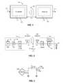
- FIG. 2shows a simplified schematic diagram of a wireless power transfer system.
- FIG. 3shows a schematic diagram of a loop antenna for use in exemplary embodiments of the present invention.
- FIG. 4is a simplified block diagram of a transmitter, in accordance with an exemplary embodiment of the present invention.
- FIG. 5is a simplified block diagram of a receiver, in accordance with an exemplary embodiment of the present invention.
- FIG. 6shows a simplified schematic of a portion of transmit circuitry for carrying out messaging between a transmitter and a receiver.
- FIG. 7shows a simplified schematic of a portion of the transmit circuitry for adjusting power levels of a transmitter.
- FIG. 8is a simplified block diagram of an AC-DC power supply that may be used to supply power to a transmitter.
- FIG. 9illustrates a Pulse Width Modulator (PWM) controller that drives two N-channel transistors to create a synchronous buck converter.
- PWMPulse Width Modulator
- FIG. 10illustrates an exemplary synchronous buck converter using a microcontroller.
- FIG. 11illustrates a host device with a transmit antenna and including receiver devices placed nearby.
- FIGS. 12A and 12Bare simplified timing diagrams illustrating a messaging protocol for communication between a transmitter and a receiver and for power transmission.
- FIG. 13A-13Cillustrates a host device with a transmit antenna and including receiver devices placed in various positions relative to the transmit antenna.
- FIGS. 14A-14Gare simplified timing diagram illustrating adaptive power control for delivering power to multiple receiver devices.
- wireless poweris used herein to mean any form of energy associated with electric fields, magnetic fields, electromagnetic fields, or otherwise that is transmitted between from a transmitter to a receiver without the use of physical electromagnetic conductors.
- FIG. 1illustrates a wireless transmission or charging system 100 , in accordance with various exemplary embodiments of the present invention.
- Input power 102is provided to a transmitter 104 for generating a radiated field 106 for providing energy transfer.
- a receiver 108couples to the radiated field 106 and generates an output power 110 for storing or consumption by a device (not shown) coupled to the output power 110 .
- Both the transmitter 104 and the receiver 108are separated by a distance 112 .
- transmitter 104 and receiver 108are configured according to a mutual resonant relationship and when the resonant frequency of receiver 108 and the resonant frequency of transmitter 104 are very close, transmission losses between the transmitter 104 and the receiver 108 are minimal when the receiver 108 is located in the “near-field” of the radiated field 106 .
- Transmitter 104further includes a transmit antenna 114 for providing a means for energy transmission and receiver 108 further includes a receive antenna 118 for providing a means for energy reception.
- the transmit and receive antennasare sized according to applications and devices to be associated therewith. As stated, an efficient energy transfer occurs by coupling a large portion of the energy in the near-field of the transmitting antenna to a receiving antenna rather than propagating most of the energy in an electromagnetic wave to the far field. When in this near-field a coupling mode may be developed between the transmit antenna 114 and the receive antenna 118 . The area around the antennas 114 and 118 where this near-field coupling may occur is referred to herein as a coupling-mode region.
- FIG. 2shows a simplified schematic diagram of a wireless power transfer system.
- the transmitter 104includes an oscillator 122 , a power amplifier 124 and a filter and matching circuit 126 .
- the oscillatoris configured to generate a desired frequency, which may be adjusted in response to adjustment signal 123 .
- the oscillator signalmay be amplified by the power amplifier 124 with an amplification amount responsive to control signal 125 .
- the filter and matching circuit 126may be included to filter out harmonics or other unwanted frequencies and match the impedance of the transmitter 104 to the transmit antenna 114 .
- the receiver 108may include a matching circuit 132 and a rectifier and switching circuit 134 to generate a DC power output to charge a battery 136 as shown in FIG. 2 or power a device coupled to the receiver (not shown).
- the matching circuit 132may be included to match the impedance of the receiver 108 to the receive antenna 118 .
- the receiver 108 and transmitter 104may communicate on a separate communication channel 119 (e.g., Bluetooth, zigbee, cellular, etc).
- antennas used in exemplary embodimentsmay be configured as a “loop” antenna 150 , which may also be referred to herein as a “magnetic” antenna.
- Loop antennasmay be configured to include an air core or a physical core such as a ferrite core. Air core loop antennas may be more tolerable to extraneous physical devices placed in the vicinity of the core. Furthermore, an air core loop antenna allows the placement of other components within the core area. In addition, an air core loop may more readily enable placement of the receive antenna 118 ( FIG. 2 ) within a plane of the transmit antenna 114 ( FIG. 2 ) where the coupled-mode region of the transmit antenna 114 ( FIG. 2 ) may be more powerful.
- the resonant frequency of the loop or magnetic antennasis based on the inductance and capacitance.
- Inductance in a loop antennais generally simply the inductance created by the loop, whereas, capacitance is generally added to the loop antenna's inductance to create a resonant structure at a desired resonant frequency.
- capacitor 152 and capacitor 154may be added to the antenna to create a resonant circuit that generates resonant signal 156 . Accordingly, for larger diameter loop antennas, the size of capacitance needed to induce resonance decreases as the diameter or inductance of the loop increases. Furthermore, as the diameter of the loop or magnetic antenna increases, the efficient energy transfer area of the near-field increases.
- resonant circuitsare possible.
- a capacitormay be placed in parallel between the two terminals of the loop antenna.
- the resonant signal 156may be an input to the loop antenna 150 .
- Exemplary embodiments of the inventioninclude coupling power between two antennas that are in the near-fields of each other.
- the near-fieldis an area around the antenna in which electromagnetic fields exist but may not propagate or radiate away from the antenna. They are typically confined to a volume that is near the physical volume of the antenna.
- magnetic type antennassuch as single and multi-turn loop antennas are used for both transmit (Tx) and receive (Rx) antenna systems since magnetic near-field amplitudes tend to be higher for magnetic type antennas in comparison to the electric near-fields of an electric-type antenna (e.g., a small dipole). This allows for potentially higher coupling between the pair.
- “electric” antennase.g., dipoles and monopoles
- a combination of magnetic and electric antennasis also contemplated.
- the Tx antennacan be operated at a frequency that is low enough and with an antenna size that is large enough to achieve good coupling (e.g., > ⁇ 4 dB) to a small Rx antenna at significantly larger distances than allowed by far field and inductive approaches mentioned earlier. If the Tx antenna is sized correctly, high coupling levels (e.g., ⁇ 1 to ⁇ 4 dB) can be achieved when the Rx antenna on a host device is placed within a coupling-mode region (i.e., in the near-field) of the driven Tx loop antenna.
- a coupling-mode regioni.e., in the near-field
- FIG. 4is a simplified block diagram of a transmitter 200 , in accordance with an exemplary embodiment of the present invention.
- the transmitter 200includes transmit circuitry 202 and a transmit antenna 204 .
- transmit circuitry 202provides RF power to the transmit antenna 204 by providing an oscillating signal resulting in generation of near-field energy about the transmit antenna 204 .
- transmitter 200may operate at the 13.56 MHz ISM band.
- Exemplary transmit circuitry 202includes a fixed impedance matching circuit 206 for matching the impedance of the transmit circuitry 202 (e.g., 50 ohms) to the transmit antenna 204 and a low pass filter (LPF) 208 configured to reduce harmonic emissions to levels to prevent self-jamming of devices coupled to receivers 108 ( FIG. 1 ).
- Other exemplary embodimentsmay include different filter topologies, including but not limited to, notch filters that attenuate specific frequencies while passing others and may include an adaptive impedance match, that can be varied based on measurable transmit metrics, such as output power to the antenna or DC current draw by the power amplifier.
- Transmit circuitry 202further includes a power amplifier 210 configured to drive an RF signal as determined by an oscillator 212 .
- the transmit circuitrymay be comprised of discrete devices or circuits, or alternately, may be comprised of an integrated assembly.
- An exemplary RF power output from transmit antenna 204may be on the order of 2.5 to 8.0 Watts.
- Transmit circuitry 202further includes a controller 214 for enabling the oscillator 212 during transmit phases (or duty cycles) for specific receivers, for adjusting the frequency of the oscillator, and for adjusting the output power level for implementing a communication protocol for interacting with neighboring devices through their attached receivers.
- the transmit circuitry 202may further include a load sensing circuit 216 for detecting the presence or absence of active receivers in the vicinity of the near-field generated by transmit antenna 204 .
- a load sensing circuit 216monitors the current flowing to the power amplifier 210 , which is affected by the presence or absence of active receivers in the vicinity of the near-field generated by transmit antenna 204 . Detection of changes to the loading on the power amplifier 210 are monitored by controller 214 for use in determining whether to enable the oscillator 212 for transmitting energy to communicate with an active receiver.
- Transmit antenna 204may be implemented as an antenna strip with the thickness, width and metal type selected to keep resistive losses low.
- the transmit antenna 204can generally be configured for association with a larger structure such as a table, mat, lamp or other less portable configuration. Accordingly, the transmit antenna 204 generally will not need “turns” in order to be of a practical dimension.
- An exemplary implementation of a transmit antenna 204may be “electrically small” (i.e., fraction of the wavelength) and tuned to resonate at lower usable frequencies by using capacitors to define the resonant frequency.
- the transmit antenna 204may be larger in diameter, or length of side if a square loop, (e.g., 0.50 meters) relative to the receive antenna, the transmit antenna 204 will not necessarily need a large number of turns to obtain a reasonable capacitance.
- the transmitter 200may gather and track information about the whereabouts and status of receiver devices that may be associated with the transmitter 200 .
- the transmitter circuitry 202may include a presence detector 280 , an enclosed detector 290 , or a combination thereof, connected to the controller 214 (also referred to as a processor herein).
- the controller 214may adjust an amount of power delivered by the amplifier 210 in response to presence signals from the presence detector 280 and the enclosed detector 290 .
- the transmittermay receive power through a number of power sources, such as, for example, an AC-DC converter (not shown) to convert conventional AC power present in a building, a DC-DC converter (not shown) to convert a conventional DC power source to a voltage suitable for the transmitter 200 , or directly from a conventional DC power source (not shown).
- power sourcessuch as, for example, an AC-DC converter (not shown) to convert conventional AC power present in a building, a DC-DC converter (not shown) to convert a conventional DC power source to a voltage suitable for the transmitter 200 , or directly from a conventional DC power source (not shown).
- the presence detector 280may be a motion detector utilized to sense the initial presence of a device to be charged that is inserted into the coverage area of the transmitter. After detection, the transmitter may be turned on and the RF power received by the device may be used to toggle a switch on the Rx device in a pre-determined manner, which in turn results in changes to the driving point impedance of the transmitter.
- the presence detector 280may be a detector capable of detecting a human, for example, by infrared detection, motion detection, or other suitable means.
- the controller 214may adjust the power output of the transmit antenna 204 to a regulatory level or lower in response to human presence and adjust the power output of the transmit antenna 204 to a level above the regulatory level when a human is outside a regulatory distance from the electromagnetic field of the transmit antenna 204 .
- the enclosed detector 290may also be referred to herein as an enclosed compartment detector or an enclosed space detector
- the enclosed detector 290may be a device such as a sense switch for determining when an enclosure is in a closed or open state.
- a power level of the transmittermay be increased.
- the transmitter 200may be programmed to shut off after a user-determined amount of time.
- This featureprevents the transmitter 200 , notably the power amplifier 210 , from running long after the wireless devices in its perimeter are fully charged. This event may be due to the failure of the circuit to detect the signal sent from either the repeater or the receive coil that a device is fully charged.
- the transmitter 200 automatic shut off featuremay be activated only after a set period of lack of motion detected in its perimeter. The user may be able to determine the inactivity time interval, and change it as desired. As a non-limiting example, the time interval may be longer than that needed to fully charge a specific type of wireless device under the assumption of the device being initially fully discharged.
- FIG. 5is a simplified block diagram of a receiver 300 , in accordance with an exemplary embodiment of the present invention.
- the receiver 300includes receive circuitry 302 and a receive antenna 304 .
- Receiver 300further couples to device 350 for providing received power thereto. It should be noted that receiver 300 is illustrated as being external to device 350 but may be integrated into device 350 .
- energyis propagated wirelessly to receive antenna 304 and then coupled through receive circuitry 302 to device 350 .
- Receive antenna 304is tuned to resonate at the same frequency, or near the same frequency, as transmit antenna 204 ( FIG. 4 ). Receive antenna 304 may be similarly dimensioned with transmit antenna 204 or may be differently sized based upon the dimensions of the associated device 350 .
- device 350may be a portable electronic device having diametric or length dimension smaller that the diameter of length of transmit antenna 204 .
- receive antenna 304may be implemented as a multi-turn antenna in order to reduce the capacitance value of a tuning capacitor (not shown) and increase the receive antenna's impedance.
- receive antenna 304may be placed around the substantial circumference of device 350 in order to maximize the antenna diameter and reduce the number of loop turns (i.e., windings) of the receive antenna and the inter-winding capacitance.
- Receive circuitry 302provides an impedance match to the receive antenna 304 .
- Receive circuitry 302includes power conversion circuitry 306 for converting a received RF energy source into charging power for use by device 350 .
- Power conversion circuitry 306includes an RF-to-DC converter 308 and may also in include a DC-to-DC converter 310 .
- RF-to-DC converter 308rectifies the RF energy signal received at receive antenna 304 into a non-alternating power while DC-to-DC converter 310 converts the rectified RF energy signal into an energy potential (e.g., voltage) that is compatible with device 350 .
- Various RF-to-DC convertersare contemplated, including partial and full rectifiers, regulators, bridges, doublers, as well as linear and switching converters.
- Receive circuitry 302may further include switching circuitry 312 for connecting receive antenna 304 to the power conversion circuitry 306 or alternatively for disconnecting the power conversion circuitry 306 . Disconnecting receive antenna 304 from power conversion circuitry 306 not only suspends charging of device 350 , but also changes the “load” as “seen” by the transmitter 200 ( FIG. 2 ).
- transmitter 200includes load sensing circuit 216 which detects fluctuations in the bias current provided to transmitter power amplifier 210 . Accordingly, transmitter 200 has a mechanism for determining when receivers are present in the transmitter's near-field.
- a receiverWhen multiple receivers 300 are present in a transmitter's near-field, it may be desirable to time-multiplex the loading and unloading of one or more receivers to enable other receivers to more efficiently couple to the transmitter.
- a receivermay also be cloaked in order to eliminate coupling to other nearby receivers or to reduce loading on nearby transmitters.
- This “unloading” of a receiveris also known herein as a “cloaking”
- this switching between unloading and loading controlled by receiver 300 and detected by transmitter 200provides a communication mechanism from receiver 300 to transmitter 200 as is explained more fully below.
- a protocolcan be associated with the switching which enables the sending of a message from receiver 300 to transmitter 200 .
- a switching speedmay be on the order of 100 ⁇ sec.
- communication between the transmitter and the receiverrefers to a device sensing and charging control mechanism, rather than conventional two-way communication.
- the transmitteruses on/off keying of the transmitted signal to adjust whether energy is available in the near-field.
- the receiversinterpret these changes in energy as a message from the transmitter.
- the receiveruses tuning and de-tuning of the receive antenna to adjust how much power is being accepted from the near-field.
- the transmittercan detect this difference in power used from the near-field and interpret these changes as a message from the receiver.
- Receive circuitry 302may further include signaling detector and beacon circuitry 314 used to identify received energy fluctuations, which may correspond to informational signaling from the transmitter to the receiver. Furthermore, signaling and beacon circuitry 314 may also be used to detect the transmission of a reduced RF signal energy (i.e., a beacon signal) and to rectify the reduced RF signal energy into a nominal power for awakening either un-powered or power-depleted circuits within receive circuitry 302 in order to configure receive circuitry 302 for wireless charging.
- signaling detector and beacon circuitry 314used to identify received energy fluctuations, which may correspond to informational signaling from the transmitter to the receiver. Furthermore, signaling and beacon circuitry 314 may also be used to detect the transmission of a reduced RF signal energy (i.e., a beacon signal) and to rectify the reduced RF signal energy into a nominal power for awakening either un-powered or power-depleted circuits within receive circuitry 302 in order to configure receive circuitry 302 for wireless charging.
- a reduced RF signal energyi.
- Receive circuitry 302further includes processor 316 for coordinating the processes of receiver 300 described herein including the control of switching circuitry 312 described herein. Cloaking of receiver 300 may also occur upon the occurrence of other events including detection of an external wired charging source (e.g., wall/USB power) providing charging power to device 350 .
- Processor 316in addition to controlling the cloaking of the receiver, may also monitor beacon circuitry 314 to determine a beacon state and extract messages sent from the transmitter. Processor 316 may also adjust DC-to-DC converter 310 for improved performance.
- the receive circuitry 320may signal a power requirement, as explained more fully below to a transmitter in the form of, for example, desired power level, maximum power level, desired current level, maximum current level, desired voltage level, and maximum voltage level. Based on these levels, and the actual amount of power received from the transmitter, the processor 316 may adjust the operation of the DC-DC converter 310 to regulate its output in the form of adjusting the current level, adjusting the voltage level, or a combination thereof.
- FIG. 6shows a simplified schematic of a portion of transmit circuitry for carrying out messaging between a transmitter and a receiver.
- a means for communicationmay be enabled between the transmitter and the receiver.
- a power amplifier 210drives the transmit antenna 204 to generate the radiated field.
- the power amplifieris driven by a carrier signal 220 that is oscillating at a desired frequency for the transmit antenna 204 .
- a transmit modulation signal 224is used to control the output of the power amplifier 210 .
- the transmit circuitrycan send signals to receivers by using an ON/OFF keying process on the power amplifier 210 .
- the transmit modulation signal 224when the transmit modulation signal 224 is asserted, the power amplifier 210 will drive the frequency of the carrier signal 220 out on the transmit antenna 204 .
- the transmit modulation signal 224When the transmit modulation signal 224 is negated, the power amplifier will not drive out any frequency on the transmit antenna 204 .
- the transmit circuitry of FIG. 6also includes a load sensing circuit 216 that supplies power to the power amplifier 210 and generates a receive signal 235 output.
- a voltage drop across resistor R sdevelops between the power in signal 226 and the power supply 228 to the power amplifier 210 . Any change in the power consumed by the power amplifier 210 will cause a change in the voltage drop that will be amplified by differential amplifier 230 .
- the transmit antennais in coupled mode with a receive antenna in a receiver (not shown in FIG. 6 ) the amount of current drawn by the power amplifier 210 will change. In other words, if no coupled mode resonance exist for the transmit antenna 210 , the power required to drive the radiated field will be a first amount.
- the receive signal 235can indicate the presence of a receive antenna coupled to the transmit antenna 235 and can also detect signals sent from the receive antenna. Additionally, a change in receiver current draw will be observable in the transmitter's power amplifier current draw, and this change can be used to detect signals from the receive antennas.
- FIG. 7shows a simplified schematic of a portion of the transmit circuitry for adjusting power levels of a transmitter.
- the controller 214may be coupled to a voltage regulator 240 , a current limiter 242 , or a combination thereof to control the amount of power delivered on the power in signal 226 relative to the supplied DC in 415 .
- some exemplary embodimentsmay include a current detector 252 and a voltage detector 250 coupled to the power in signal 226 and used to provide feedback to the controller regarding the consumption of power.
- the load sensing circuit 216 of FIG. 6is one example of a suitable current detector.
- powermay be delivered, using the transmit circuitry 202 and transmit antenna 204 , to receiver devices needing charge by placing the receiver devices in the vicinity of a coupling-mode region of the transmit antenna.
- the transmittercan cycle power sequentially to all of the receiver devices to be charged based on power level, time, and the like.
- Receiver devicesmay communicate device power requirements and other information to the transmitter. With this power requirement information, the transmitter can tailor the amount of power that is delivered to each receiver device by adjusting the amount of power transmitted, adjusting the amount of time that power is transmitted, or a combination thereof.
- Combinations of the voltage regulator 240 and the current limiter 242may be used to implement the proper circuitry for adjusting power levels of the transmitter.
- An adjustable voltage regulator circuitmay, for example, include an adjustable potentiometer, a rectifier, possibly a smoothing circuit and possibly a band-gap reference circuit.
- Example of some voltage regulator circuits suitable for use with embodiments of the inventionare illustrated and discussed with reference to FIGS. 8 , 9 , and 10 below.
- a receiver device requiring chargingmay signal its power requirement needs, for example, in terms of current and voltage to the transmitter.
- a protocolmay be included wherein each receiver device wanting charging signals its power ratings including its peak voltage and current levels. Additionally, a recommended level of current and voltage may also be signaled. Further, an identifier for each device to be charged can likewise be signaled.
- the processor 214may then control, for example, the power that is delivered to the power amplifier 210 ( FIG. 6 ) through the power in signal 226 .
- a voltage detector 250may be included, for example, either separately as shown in FIG. 7 or as part of the voltage regulator 240 .
- the voltage detector 250forms a feedback path with the controller 214 to adjust power levels on the power in signal 226 .
- the controller 214may adjust a level within the voltage regulator 240 within specified limits to provide optimal charging to a device to be charged.
- that optimal levelmay be set to not exceed the power rating of the device as determined by the fact that power is the product of voltage and current.
- a current detector 252may be included, for example, either separately as shown in FIG. 7 or as part of the current regulator 242 .
- the voltage detector 250forms a feedback path with the controller 214 to adjust power levels on the power in signal 226 .
- the controller 214may adjust a level within the current limiter 242 within specified limits to provide optimal charging to a device to be charged.
- the optimal levelmay be set to not exceed the power rating of the device as determined by the fact that power is the product of voltage and current.
- the power drawn by each receiver devicemay be monitored in connection with the voltage and current detectors providing power component (voltage or current) threshold detection.
- the controller 214may adjust voltage and current to different levels for each receiver device that is being charged throughout a charging process.
- the receiver devicesmay signal power requirement needs via a wireless charging signaling protocol as discussed above.
- a separate communication channel 119e.g., Bluetooth, zigbee, cellular, etc. may be used to signal power requirements.
- Exemplary embodiments of the inventionare directed to a dynamic transmit radiated power level control by utilizing adaptive control of the drive voltage, drive current, or a combination thereof to drive the power amplifier 210 ( FIG. 6 ). Changing the drive level changes the RF power output from the PA and hence the power transmitted to the receive devices being charged.
- Some exemplary information used to define power levelsmay include:
- the transmit sourcecan be adjusted to this level during the time slot over which it is getting charged, as explained more fully below.
- the power level delivered to each devicecan be independently customized for that device without impacting any of the other devices.
- knowledge of the current battery charge levels of a device being chargedallows for the radiated RF level to be optimized based on the current battery charge level of the device. Both techniques help to minimize power that would normally be wasted if a fixed transmit power level were implemented.
- comparing the power level absorbed by each device (item 3) to the power transmitted from the transmittergives an indication of the total power radiated to the local environment which in turn is proportional to the transmitter SAR level.
- Thisallows a means to maximize the radiated power to each device based on each device's coupling ratios to the transmitter while still maintaining acceptable SAR levels.
- oneis able to improve the power delivered to each device individually rather than be limited to a lower fixed power level dictated by the device with poor coupling to the transmitter.
- adjustable radiated powerallows for a lower power beacon mode that reduces transmitter AC power consumption when not in charging mode and also reduces the interference to locally-situated electronics.
- FIGS. 8 , 9 , and 10illustrate exemplary circuitry that may be used to regulate and adjust power levels for the power amplifier 210 and other transmit circuitry 202 .
- an AC-DC power supply 400converts 120 volts AC 405 to the various DC voltages that may be required by the transmitter, such as, for example, 5 volt and 100 mA auxiliary power to run the transmit circuitry 202 and 5-12 volt and 500 mA main power to run the power amplifier 210 , which drives the transmit antenna 204 .
- An AC-DC converter 410generates an intermediate DC voltage 415 (also referred to herein as “DC in”) for a circuitry regulator 420 and a PA regulator 450 .
- the circuitry regulator 420provides general power 425 for the transmit circuitry 202 and the PA regulator provides variable power levels for the power in signal 226 to drive the PA 210 .
- the AC-DC converter 410may be, for example, a conventional “wall wart” that allows an Underwriter Laboratories (UL) and Canadian Standards Association (CSA) approved power supply to be the “certified” section of the system while keeping costs down. Quasi-regulated (e.g., about 10%) wall warts are inexpensive and are available from a wide variety of vendors.
- ULUnderwriter Laboratories
- CSACanadian Standards Association
- the circuitry regulator 420 and a PA regulator 450may be implemented as buck voltage converters.
- the dual buck design of a circuitry regulator 420 and a PA regulator 450may keep efficiencies high, at the expense of additional switch-mode controllers, Field Effect Transistors (FETs), capacitors, and inductors.
- FETsField Effect Transistors
- the circuitry regulator 420may be a low-power fixed-output buck converter that provides 5 volts for the controller 214 and other circuitry as illustrated in FIG. 4 .
- the PA regulator 450may be a higher power variable-output buck converter that supplies a varying voltage to the power amplifier to control the power output of the transmitter.
- the power amplifier supply 226is controllable by a control signal 452 from the transmit circuitry 202 to the PA regulator 450 , which varies the transmitted RF power over, for example, a range of about 50 mW to about 5 watts.
- FIG. 9illustrates a PA regulator 450 A implemented as a Pulse Width Modulator (PWM) controller 460 (such as a Linear Technology LTC3851) that drives two N-channel transistors to comprise a synchronous buck converter.
- PWMPulse Width Modulator
- a small inductor, a resistor ladder, and an output capacitorfilter the output of the transistors to complete the buck converter.
- the buck converterconverts and regulates the DC in voltage 415 to a DC out voltage 226 .
- Power outputmay be controlled, for example, by a digital (programmable) potentiometer 465 controlled by the control signal 452 .
- the control signal 452may be driven by the controller 214 ( FIG. 4 ) such that the DC out voltage 226 can be set anywhere from, for example, 5 to 12 volts DC.
- PA regulator 450 Atakes very little controller overhead, and may be configured to have guaranteed loop stability under conditions of rapidly changing load with over 90% efficiency.
- FIG. 10illustrates a PA regulator 450 B as a synchronous buck converter using a microcontroller 470 .
- the microcontroller 470may be dedicated to the synchronous buck converter function.
- the controller 214 of the transmitter 200FIG. 4
- the buck converterconverts and regulates the DC in voltage 415 to a DC out voltage 226 .
- the microcontroller 470may directly drive a P-channel and an N-channel FET to provide the switch control for the buck converter.
- a small inductor, a resistor ladder, and an output capacitorfilter the output of the transistors to complete the buck converter.
- Feedbackmay be directly into an A/D input of the microcontroller 470 as a voltage sensing operation.
- the control signal 452may be embodied as a sampled version of the voltage on DC out 226 .
- the microcontroller 470may compare actual output on DC out 226 to desired output and correct the PWM signal accordingly. Since frequencies may be much lower for a microcontroller 470 implementation, a larger inductor may be required, which is not a big problem in the transmitter. A microcontroller 470 implementation may be considerably cheaper, since no separate PWM controller is required.
- FIG. 11illustrates a host device 510 with transmit circuitry 202 and a transmit antenna 204 .
- Receiver devices 520are shown placed within the coupling-mode region of the transmit antenna 204 .
- the receiver devicesmay include receive antennas 304 and receive circuitry 302 as shown in FIG. 5 .
- the host device 410is illustrated as a charging mat, but could be integrated into furniture or building elements such as walls, ceilings, and floors.
- the host device 510may be an item such as, for example, a handbag, backpack, or briefcase with a transmitter built in.
- the host devicemay be a portable transmitter specifically designed for a user to transport and charge receiver devices 520 , such as a charging bag.
- Coplanarmeans that the transmit antenna and receive antenna have planes that are substantially aligned (i.e., have surface normals pointing in substantially the same direction) and with no distance (or a small distance) between the planes of the transmit antenna and the receive antenna.
- Coaxialmeans that the transmit antenna and receive antenna have planes that are substantially aligned (i.e., have surface normals pointing in substantially the same direction) and the distance between the two planes is not trivial and furthermore, the surface normal of the transmit antenna and the receive antenna lie substantially along the same vector, or the two normals are in echelon.
- Coplanar placementsmay have relatively high coupling efficiencies. However, coupling may vary depending on where the receive antennas are placed relative to the transmit antenna. For example, a coplanar placement point outside of the transmit loop antenna may not couple as efficiently as a coplanar placement point inside the transmit loop. Furthermore, coplanar placement points within the transmit loop, but at different locations relative to the loop, may have different coupling efficiencies.
- Coaxial placementsmay have lower coupling efficiencies. However, coupling efficiencies may be improved with the used of repeater antennas, such as are described in U.S. Utility patent application Ser. No. 12/249,875 entitled “METHOD AND APPARATUS FOR AN ENLARGED WIRELESS CHARGING AREA” filed on Oct. 10, 2008, the contents of which is incorporated by reference herein in its entirety.
- FIG. 12Ais a simplified timing diagram illustrating an exemplary messaging protocol for communication between a transmitter and a receiver using the signaling techniques discussed above.
- signals from the transmitter to the receiverare referred to herein as a “forward link” and use a simple AM modulation between normal power transmission and lower power transmission.
- Other modulation techniquesare also contemplated.
- a signal presentmay be interpreted as a “1” and no signal present may be interpreted as a “0” (i.e., on-off keying).
- Reverse link signalingis provided by modulation of power drawn by the receive device, which can be detected by the load sensing circuit in the transmitter.
- higher power statesmay be interpreted as a 1 and lower power states may be interpreted as a 0.
- the transmittermust be on for the receiver to be able to perform the reverse link signaling.
- the receivershould not perform reverse link signaling during forward link signaling.
- two receive devicesattempt to perform reverse link signaling at the same time a collision may occur, which will make it difficult, if not impossible for the transmitter to decode a proper reverse link signal.
- FIG. 12Aillustrates a simple and low power form of the messaging protocol.
- a synchronization pulse 620is repeated every recurring period 610 (about one second in the exemplary embodiment) to define the beginning of the recurring period.
- the sync pulse on timemay be about 40 mS.
- the recurring period 610with at least a synchronization pulse 620 , may be repeated indefinitely while the transmitter is on.
- “synchronization pulse”is somewhat of a misnomer because the synchronization pulse 620 may be a steady frequency during the pulse period 620 .
- the synchronization pulse 620may also include signaling at the resonant frequency with the ON/OFF keying discussed above and as illustrated by the “hatched” pulse 620 .
- FIG. 12Aillustrates a minimal power state wherein power at the resonant frequency is supplied during the synchronization pulse 420 and the transmit antenna is off during a power period 650 . All receiver devices are allowed to receive power during the synchronization pulse 420 .
- FIG. 12Billustrates the recurring period 610 with a synchronization pulse 620 , a reverse link period 630 and a power period 650 ′ wherein the transmit antenna is on and supplying full power by oscillating at the resonant frequency and not performing any signaling.
- the power period 450 ′may be segmented into different periods for multiple receiver devices as is explained below.
- FIG. 12Bshows three power segments Pd 1 , Pd 2 , and Pdn for three different receiver devices.
- the on-off keying communication protocol discussed abovemay be expanded to enable each receiver device to request charge and indicate desired power parameters as discussed above.
- a receiver devicemay identify itself with a unique identifier, such as, for example a serial number or a tag associating the receiver device with a specific user.
- the requesting receiver devicemay also communicate additional information such as class of device (e.g., camera, cell phone, media player, personal digital assistant).
- Receiver informationmay include items such as; unique device identifiers, device types, contact information, and user-programmed information about the device.
- the devicemay be a music player, from a specific manufacturer, that is tagged with a user's name.
- the devicemay be an electronic book, from a specific manufacturer, with a specific serial number that is tagged with a user's name.
- the receiver and transmittermay communicate on a separate communication channel 119 (e.g., Bluetooth, zigbee, cellular, etc.).
- a separate communication channelWith a separate communication channel, the recurring period need not include any communication periods and the entire time may be devoted to the power period 650 ′.
- the transmittermay still allocate time slots to each receiver device (communicated over the separate communication channel) and each receiver device only gets on the bus for its allocated power segment Pdn.
- each receiver devicemay need more power, perhaps due to a higher power task it must perform periodically.
- one receiver devicemay need less power, perhaps due to a battery being fully charged. In such a case, the system may want to distribute that receiver device's power allocation to other devices.
- Time division multiplexingAnother way to allocate power between multiple receiver devices is time division multiplexing, where one receiver device at a time is enabled to receive power. All receiver devices not receiving power are disabled from receiving power so that they do not interact with the RF/inductive environment.
- Time division multiplexingrequires a controller that can apportion power between several powered devices, and can optionally make decisions on unequal allocations of power.
- a transmittermay reduce the length of, or eliminate, the power segment to a device that is fully charged.
- Time division multiplexingmay have the drawback of losing some efficiency, since summing the coupling efficiency of all receiver devices receiving simultaneously may not equal the efficiency of each receiver device receiving power sequentially.
- a receiver device that is offmay have to store power for a long time until its next on period, thus requiring a larger/more expensive charge storage device.
- Exemplary embodiments of the disclosureare directed to a hybrid technique.
- a number of receiver devicesshare a wireless charging area. Initially, they may all share receive power simultaneously.
- a control systemwhich includes feedback from the receiver devices, notes how much power each receiver device is actually receiving, and if needed, adjusts power via a time division multiplexing approach, a power level adjustment approach, or a combination thereof.
- each receiver devicewill receive power for most of the time.
- some receiver devicesmay be turned off or disabled from receiving power to reduce their total power received. For example, a receiver device that is placed on the transmit coil so that it receives most of the power might be turned off for part of the time so that other receiver devices receive more power.
- the imbalance caused by the placement of various receiver devicesmay be corrected.
- Another examplemight be two receiver devices that are placed so they both share power, and initially both are on 100% of the time. As one device finishes charging its battery, it could begin to turn itself off for a larger and larger percentage of the time to allow more power to reach the other device. Alternatively, the transmitter could begin allocating a smaller and smaller time slot for the almost charged receiver device to allow more power to reach the other receiver devices.
- FIG. 13A-13Cillustrates a host device 150 with a transmit antenna 204 and including receiver devices (Dev 1 and Dev 2 ) placed in various positions relative to the transmit antenna 204 .
- receiver devicesDev 1 and Dev 2
- FIG. 13A-13Cillustrates a host device 150 with a transmit antenna 204 and including receiver devices (Dev 1 and Dev 2 ) placed in various positions relative to the transmit antenna 204 .
- receiver devicesFor simplicity, only two receiver devices are discussed herein but use of multiple devices is also contemplated to be within the scope of the teachings of the disclosure and modification for such would be apparent to a person of ordinary skill in the art.
- FIG. 13Aillustrates a scenario where both receiver devices (Dev 1 and Dev 2 ) are positioned to receive substantially equal amounts of power from the transmit antenna 204 , such as by being about the same distance away from the perimeter of the transmit antenna.
- receiver devices Dev 1 and Dev 2are both placed near the center of the transmit antenna 204 .
- the receiver devices Dev 1 and Dev 2are placed away from each other but about the same distance from the perimeter of the transmit antenna 204 .
- the receiver devices Dev 1 and Dev 2do not have to be near each other or in the same geographical location within the powering region to receive the same amount of power from the transmit antenna 204 .
- the receiver devices Dev 1 and Dev 2may receive less power from the transmit antenna 204 than in a FIG. 4B setting.
- the amount of power received in one of the devicesis substantially equal to the amount of power received in the other device.
- FIG. 13Cillustrates a scenario wherein the receiver devices Dev 1 and Dev 2 are positioned to receive unequal amount of power from the transmit antenna 204 .
- receiver device Dev 1is placed near the center of the transmit antenna 204 , and will likely receive less power than receiver device Dev 2 placed closer to the transmit antenna 204 .
- Dev 2would charge faster than Dev 1 and therefore become fully charged sooner than Dev 1 .
- FIGS. 14A-14Gare simplified timing diagram illustrating adaptive power control for delivering power to multiple receiver devices. For simplicity, only two devices are discussed herein but use of multiple devices is also contemplated to be within the scope of the teachings of the disclosure and modification for such would be apparent to a person of ordinary skill in the art.
- a case 0 scenarioshows a time line 700 to illustrate when a single receiver device is placed within the powering region of the transmitter antenna 204 .
- the single receiver devicereceives substantially all of the power provided by the transmit antenna 204 during each recurring period 610 .
- a portion 620 of the recurring period 610maybe spent on optional signaling.
- a case 2 scenarioillustrated by times lines 721 and 722 , uses time multiplexing.
- each of the receiver devices Dev 1 and Dev 2receives an equal amount of power during the recurring period 610 .
- Dev 1is enabled to receive 100% of the power for 50% of the recurring period 610
- Dev 2is enabled to receive 100% of the power for the other 50% of the recurring period 610 .
- Signaling periods 620may also be used to allow communication between transmitter and receiver, and may reduce the charging time available for both devices.
- a case 3 scenarioillustrates times lines 731 and 732 , wherein both receiver devices Dev 1 and Dev 2 may be enabled to receive power during the signaling periods 610 . Even though signaling may be occurring, the receiver devices Dev 1 and Dev 2 can still extract power from the signal. Thus, in case 3 each of the receive devices is enabled to receive power during the signaling periods 620 and thus receive about 50% of the power during the signaling periods 620 .
- the power portion of the recurring period 610i.e., the portion of the recurring period 610 not used by the signaling period 620 ) may be equally split to time division multiplex between receiver device Dev 1 and receiver device Dev 2 .
- a case 4 scenarioshows a time line 741 for receiver device Dev 1 and a time line 742 for receiver device Dev 2 .
- the receiver devices Dev 1 and Dev 2are positioned to receive unequal amount of power from the transmit antenna 204 , such as receiver device Dev 1 placed near the center of the transmit antenna 204 and receiving less power than receiver device Dev 2 placed closer to the transmit antenna 204 (as shown in FIG. 13C ).
- Each of receiver devices Dev 1 and Dev 2rely on their coupling to the transmit antenna 204 to apportion the power between the two devices in the powering region.
- a case 5 scenarioshows a time line 751 for receiver device Dev 1 and a time line 752 for receiver device Dev 2 .
- the receiver devices Dev 1 and Dev 2are positioned to receive unequal amount of power from the transmit antenna in a similar manner to that of FIG. 14E .
- each receiver devicerelies partly upon its relative coupling to the transmit antenna 204 to apportion power, each receiver device can also decouple itself from the transmit antenna 204 if needed. If a 50/50 power split is desired, receiver device Dev 2 can disable itself from receiving power for a P 2 portion of the recurring period 610 , while Dev 1 remains enabled to receive 100% of the power during the P 1 portion.
- both receiver devicesremain on such that receiver device Dev 1 receives about 25% of the power and receiver device Dev 2 receives about 75% of the power.
- the lengths of the P 1 portion and P 2 portionmay be adjusted such that about 50% of the power (or other apportionment, if desired) is allocated to each receiver device Dev 1 and Dev 2 .
- Case 5is similar to case 2 , but requires less off-time. For example in case 5 receive device Dev 1 is never turned disabled from receiving power and just receives more power during the P 2 portion due to receiver device Dev 2 being disabled.
- receiver device Dev 1is disabled from receiving power and the power output of the transmit antenna is set to about 3 Watts, which is mostly consumed by receiver device Dev 2 .
- receiver device Dev 2is disabled from receiving power and the power output of the transmit antenna is set to about 4 Watts, which is mostly consumed by receiver device Dev 1 .
- FIGS. 14A-Gare given as examples of some possible scenarios. A person of ordinary skill in the art would recognize that many other scenarios involving more receiver devices and various power output levels are contemplated within the scope of the invention.
- DSPDigital Signal Processor
- ASICApplication Specific Integrated Circuit
- FPGAField Programmable Gate Array
- a general purpose processormay be a microprocessor, but in the alternative, the processor may be any conventional processor, controller, microcontroller, or state machine.
- a software modulemay reside in Random Access Memory (RAM), flash memory, Read Only Memory (ROM), Electrically Programmable ROM (EPROM), Electrically Erasable Programmable ROM (EEPROM), registers, hard disk, a removable disk, a CD-ROM, or any other form of storage medium known in the art.
- An exemplary storage mediumis coupled to the processor such that the processor can read information from, and write information to, the storage medium.
- the storage mediummay be integral to the processor.
- the processor and the storage mediummay reside in an ASIC.
- the ASICmay reside in a user terminal.
- the processor and the storage mediummay reside as discrete components in a user terminal.
- the functions describedmay be implemented in hardware, software, firmware, or any combination thereof. If implemented in software, the functions may be stored on or transmitted over as one or more instructions or code on a computer-readable medium.
- Computer-readable mediaincludes both computer storage media and communication media including any medium that facilitates transfer of a computer program from one place to another.
- a storage mediamay be any available media that can be accessed by a computer.
- such computer-readable mediacan comprise RAM, ROM, EEPROM, CD-ROM or other optical disk storage, magnetic disk storage or other magnetic storage devices, or any other medium that can be used to carry or store desired program code in the form of instructions or data structures and that can be accessed by a computer.
- any connectionis properly termed a computer-readable medium.
- the softwareis transmitted from a website, server, or other remote source using a coaxial cable, fiber optic cable, twisted pair, digital subscriber line (DSL), or wireless technologies such as infrared, radio, and microwave
- the coaxial cable, fiber optic cable, twisted pair, DSL, or wireless technologiessuch as infrared, radio, and microwave are included in the definition of medium.
- Disk and discincludes compact disc (CD), laser disc, optical disc, digital versatile disc (DVD), floppy disk and blu-ray disc where disks usually reproduce data magnetically, while discs reproduce data optically with lasers. Combinations of the above should also be included within the scope of computer-readable media.
Landscapes
- Engineering & Computer Science (AREA)
- Computer Networks & Wireless Communication (AREA)
- Power Engineering (AREA)
- Signal Processing (AREA)
- Charge And Discharge Circuits For Batteries Or The Like (AREA)
- Transmitters (AREA)
- Near-Field Transmission Systems (AREA)
Abstract
Description
- U.S. Provisional Patent Application 61/146,586 entitled “POWER SHARING FOR WIRELESS POWER DEVICES” filed on Jan. 22, 2009.
- U.S. Provisional Patent Application 61/151,156 entitled “DYNAMIC POWER CONTROL METHODOLOGY FOR WIRELESS CHARGING” filed on Feb. 9, 2009.
- U.S. Provisional Patent Application 61/183,907 entitled “ADAPTIVE POWER CONTROL FOR WIRELESSLY CHARGING DEVICES” filed on Jun. 3, 2009.
Claims (43)
Priority Applications (14)
| Application Number | Priority Date | Filing Date | Title |
|---|---|---|---|
| US12/616,034US8497658B2 (en) | 2009-01-22 | 2009-11-10 | Adaptive power control for wireless charging of devices |
| KR1020177021495AKR20170091781A (en) | 2009-01-22 | 2010-01-22 | Adaptive power control for wireless charging |
| KR1020157001693AKR20150020710A (en) | 2009-01-22 | 2010-01-22 | Adaptive power control for wireless charging |
| KR1020157001692AKR101614260B1 (en) | 2009-01-22 | 2010-01-22 | Adaptive power control for wireless charging |
| CN201410815409.9ACN104485722B (en) | 2009-01-22 | 2010-01-22 | Self-adaptive electric power for wireless charging controls |
| JP2011548157AJP2012516131A (en) | 2009-01-22 | 2010-01-22 | Adaptive power control for wireless charging |
| PCT/US2010/021873WO2010085701A2 (en) | 2009-01-22 | 2010-01-22 | Adaptive power control for wireless charging |
| TW99101797ATW201042876A (en) | 2009-01-22 | 2010-01-22 | Adaptive power control for wireless charging |
| EP10701604.0AEP2389718B1 (en) | 2009-01-22 | 2010-01-22 | Adaptive power control for wireless charging |
| CN201080005299.XACN102292896B (en) | 2009-01-22 | 2010-01-22 | Adaptive power control for wireless charging |
| KR1020117019378AKR101578966B1 (en) | 2009-01-22 | 2010-01-22 | Adaptive power control for wireless charging |
| US13/918,365US8823319B2 (en) | 2009-01-22 | 2013-06-14 | Adaptive power control for wireless charging of devices |
| US14/468,104US9559526B2 (en) | 2009-01-22 | 2014-08-25 | Adaptive power control for wireless charging of devices |
| JP2014181105AJP5921625B2 (en) | 2009-01-22 | 2014-09-05 | Adaptive power control for wireless charging |
Applications Claiming Priority (4)
| Application Number | Priority Date | Filing Date | Title |
|---|---|---|---|
| US14658609P | 2009-01-22 | 2009-01-22 | |
| US15115609P | 2009-02-09 | 2009-02-09 | |
| US18390709P | 2009-06-03 | 2009-06-03 | |
| US12/616,034US8497658B2 (en) | 2009-01-22 | 2009-11-10 | Adaptive power control for wireless charging of devices |
Related Child Applications (1)
| Application Number | Title | Priority Date | Filing Date |
|---|---|---|---|
| US13/918,365ContinuationUS8823319B2 (en) | 2009-01-22 | 2013-06-14 | Adaptive power control for wireless charging of devices |
Publications (2)
| Publication Number | Publication Date |
|---|---|
| US20100181961A1 US20100181961A1 (en) | 2010-07-22 |
| US8497658B2true US8497658B2 (en) | 2013-07-30 |
Family
ID=42336412
Family Applications (3)
| Application Number | Title | Priority Date | Filing Date |
|---|---|---|---|
| US12/616,034Active2031-03-12US8497658B2 (en) | 2009-01-22 | 2009-11-10 | Adaptive power control for wireless charging of devices |
| US13/918,365ActiveUS8823319B2 (en) | 2009-01-22 | 2013-06-14 | Adaptive power control for wireless charging of devices |
| US14/468,104Active2029-12-29US9559526B2 (en) | 2009-01-22 | 2014-08-25 | Adaptive power control for wireless charging of devices |
Family Applications After (2)
| Application Number | Title | Priority Date | Filing Date |
|---|---|---|---|
| US13/918,365ActiveUS8823319B2 (en) | 2009-01-22 | 2013-06-14 | Adaptive power control for wireless charging of devices |
| US14/468,104Active2029-12-29US9559526B2 (en) | 2009-01-22 | 2014-08-25 | Adaptive power control for wireless charging of devices |
Country Status (7)
| Country | Link |
|---|---|
| US (3) | US8497658B2 (en) |
| EP (1) | EP2389718B1 (en) |
| JP (2) | JP2012516131A (en) |
| KR (4) | KR101578966B1 (en) |
| CN (2) | CN102292896B (en) |
| TW (1) | TW201042876A (en) |
| WO (1) | WO2010085701A2 (en) |
Cited By (199)
| Publication number | Priority date | Publication date | Assignee | Title |
|---|---|---|---|---|
| US20120112554A1 (en)* | 2010-11-10 | 2012-05-10 | Nam Yun Kim | Wireless power transmission system, and method of controlling transmission and reception of resonance power |
| US20120139357A1 (en)* | 2010-12-01 | 2012-06-07 | Triune Ip Llc | Coupled Inductor Power Transfer System |
| US20120309306A1 (en)* | 2011-06-01 | 2012-12-06 | Samsung Electronics Co., Ltd. | Apparatus and method to perform communication in wireless power transmission system |
| US20130043835A1 (en)* | 2011-08-18 | 2013-02-21 | Samsung Electronics Co., Ltd. | Apparatus and method for non-contact recharging and near field communication in a portable electronic device |
| US20130162204A1 (en)* | 2011-12-21 | 2013-06-27 | Hanrim Postech Co., Ltd. | Apparatus for detecting signal and wireless power transmitting apparatus having the same |
| US20130207599A1 (en)* | 2012-02-10 | 2013-08-15 | Sandisk Technologies Inc. | Regulation of wirelessly charging multiple devices from the same source |
| US20140217969A1 (en)* | 2011-09-06 | 2014-08-07 | Sony Corporation | Feed unit, electronic unit, and feed system |
| CN104582162A (en)* | 2014-12-26 | 2015-04-29 | 生迪光电科技股份有限公司 | Wireless power supply LED illuminating device, system and power supply method |
| US20150249360A1 (en)* | 2012-09-05 | 2015-09-03 | Renesas Electronics Corporation | Non-contact charging device, and non-contact power supply system using same |
| US20150291042A1 (en)* | 2012-08-31 | 2015-10-15 | Siemens Aktiengesellschaft | Battery charging system and method for cableless charging of a battery |
| US9196964B2 (en) | 2014-03-05 | 2015-11-24 | Fitbit, Inc. | Hybrid piezoelectric device / radio frequency antenna |
| US20160020640A1 (en)* | 2014-07-21 | 2016-01-21 | Jessica Kristin Rogers | Portable Method for Charging Mobile Devices |
| US9450456B2 (en) | 2008-04-21 | 2016-09-20 | Qualcomm Incorporated | System and method for efficient wireless power transfer to devices located on and outside a charging base |
| US9520638B2 (en) | 2013-01-15 | 2016-12-13 | Fitbit, Inc. | Hybrid radio frequency / inductive loop antenna |
| US9520739B2 (en) | 2012-03-12 | 2016-12-13 | Renesas Electronics Corporation | Wireless charging circuit, wireless charging system and semiconductor device |
| US9559526B2 (en) | 2009-01-22 | 2017-01-31 | Qualcomm Incorporated | Adaptive power control for wireless charging of devices |
| US9711974B2 (en) | 2012-03-19 | 2017-07-18 | Lg Innotek Co., Ltd. | Wireless power transmitting apparatus and method thereof |
| US20170288426A1 (en)* | 2016-03-31 | 2017-10-05 | Pincraft Engineering Inc. | Multi charging device enabled by current and voltage control |
| US9787103B1 (en) | 2013-08-06 | 2017-10-10 | Energous Corporation | Systems and methods for wirelessly delivering power to electronic devices that are unable to communicate with a transmitter |
| US9800172B1 (en) | 2014-05-07 | 2017-10-24 | Energous Corporation | Integrated rectifier and boost converter for boosting voltage received from wireless power transmission waves |
| US9812890B1 (en) | 2013-07-11 | 2017-11-07 | Energous Corporation | Portable wireless charging pad |
| US9831718B2 (en) | 2013-07-25 | 2017-11-28 | Energous Corporation | TV with integrated wireless power transmitter |
| US9838083B2 (en) | 2014-07-21 | 2017-12-05 | Energous Corporation | Systems and methods for communication with remote management systems |
| US9843213B2 (en) | 2013-08-06 | 2017-12-12 | Energous Corporation | Social power sharing for mobile devices based on pocket-forming |
| US9843229B2 (en) | 2013-05-10 | 2017-12-12 | Energous Corporation | Wireless sound charging and powering of healthcare gadgets and sensors |
| US9843201B1 (en) | 2012-07-06 | 2017-12-12 | Energous Corporation | Wireless power transmitter that selects antenna sets for transmitting wireless power to a receiver based on location of the receiver, and methods of use thereof |
| US9847669B2 (en) | 2013-05-10 | 2017-12-19 | Energous Corporation | Laptop computer as a transmitter for wireless charging |
| US9847679B2 (en) | 2014-05-07 | 2017-12-19 | Energous Corporation | System and method for controlling communication between wireless power transmitter managers |
| US9847677B1 (en) | 2013-10-10 | 2017-12-19 | Energous Corporation | Wireless charging and powering of healthcare gadgets and sensors |
| US9859756B2 (en) | 2012-07-06 | 2018-01-02 | Energous Corporation | Transmittersand methods for adjusting wireless power transmission based on information from receivers |
| US9867062B1 (en) | 2014-07-21 | 2018-01-09 | Energous Corporation | System and methods for using a remote server to authorize a receiving device that has requested wireless power and to determine whether another receiving device should request wireless power in a wireless power transmission system |
| US9871301B2 (en) | 2014-07-21 | 2018-01-16 | Energous Corporation | Integrated miniature PIFA with artificial magnetic conductor metamaterials |
| US9871387B1 (en) | 2015-09-16 | 2018-01-16 | Energous Corporation | Systems and methods of object detection using one or more video cameras in wireless power charging systems |
| US9871398B1 (en) | 2013-07-01 | 2018-01-16 | Energous Corporation | Hybrid charging method for wireless power transmission based on pocket-forming |
| US9876379B1 (en) | 2013-07-11 | 2018-01-23 | Energous Corporation | Wireless charging and powering of electronic devices in a vehicle |
| US9876648B2 (en) | 2014-08-21 | 2018-01-23 | Energous Corporation | System and method to control a wireless power transmission system by configuration of wireless power transmission control parameters |
| US9882427B2 (en) | 2013-05-10 | 2018-01-30 | Energous Corporation | Wireless power delivery using a base station to control operations of a plurality of wireless power transmitters |
| US9887739B2 (en) | 2012-07-06 | 2018-02-06 | Energous Corporation | Systems and methods for wireless power transmission by comparing voltage levels associated with power waves transmitted by antennas of a plurality of antennas of a transmitter to determine appropriate phase adjustments for the power waves |
| US9893768B2 (en) | 2012-07-06 | 2018-02-13 | Energous Corporation | Methodology for multiple pocket-forming |
| US9893555B1 (en) | 2013-10-10 | 2018-02-13 | Energous Corporation | Wireless charging of tools using a toolbox transmitter |
| US9893538B1 (en) | 2015-09-16 | 2018-02-13 | Energous Corporation | Systems and methods of object detection in wireless power charging systems |
| US9893554B2 (en) | 2014-07-14 | 2018-02-13 | Energous Corporation | System and method for providing health safety in a wireless power transmission system |
| US9899861B1 (en) | 2013-10-10 | 2018-02-20 | Energous Corporation | Wireless charging methods and systems for game controllers, based on pocket-forming |
| US9899744B1 (en) | 2015-10-28 | 2018-02-20 | Energous Corporation | Antenna for wireless charging systems |
| US9899873B2 (en) | 2014-05-23 | 2018-02-20 | Energous Corporation | System and method for generating a power receiver identifier in a wireless power network |
| US9906275B2 (en) | 2015-09-15 | 2018-02-27 | Energous Corporation | Identifying receivers in a wireless charging transmission field |
| US9906065B2 (en) | 2012-07-06 | 2018-02-27 | Energous Corporation | Systems and methods of transmitting power transmission waves based on signals received at first and second subsets of a transmitter's antenna array |
| US9912199B2 (en) | 2012-07-06 | 2018-03-06 | Energous Corporation | Receivers for wireless power transmission |
| US9917477B1 (en) | 2014-08-21 | 2018-03-13 | Energous Corporation | Systems and methods for automatically testing the communication between power transmitter and wireless receiver |
| US9923386B1 (en) | 2012-07-06 | 2018-03-20 | Energous Corporation | Systems and methods for wireless power transmission by modifying a number of antenna elements used to transmit power waves to a receiver |
| US9935482B1 (en) | 2014-02-06 | 2018-04-03 | Energous Corporation | Wireless power transmitters that transmit at determined times based on power availability and consumption at a receiving mobile device |
| US9941754B2 (en) | 2012-07-06 | 2018-04-10 | Energous Corporation | Wireless power transmission with selective range |
| US9939864B1 (en) | 2014-08-21 | 2018-04-10 | Energous Corporation | System and method to control a wireless power transmission system by configuration of wireless power transmission control parameters |
| US9941752B2 (en) | 2015-09-16 | 2018-04-10 | Energous Corporation | Systems and methods of object detection in wireless power charging systems |
| US9948135B2 (en) | 2015-09-22 | 2018-04-17 | Energous Corporation | Systems and methods for identifying sensitive objects in a wireless charging transmission field |
| US9954374B1 (en) | 2014-05-23 | 2018-04-24 | Energous Corporation | System and method for self-system analysis for detecting a fault in a wireless power transmission Network |
| US9966765B1 (en) | 2013-06-25 | 2018-05-08 | Energous Corporation | Multi-mode transmitter |
| US9966784B2 (en) | 2014-06-03 | 2018-05-08 | Energous Corporation | Systems and methods for extending battery life of portable electronic devices charged by sound |
| US9965009B1 (en) | 2014-08-21 | 2018-05-08 | Energous Corporation | Systems and methods for assigning a power receiver to individual power transmitters based on location of the power receiver |
| US9967743B1 (en) | 2013-05-10 | 2018-05-08 | Energous Corporation | Systems and methods for using a transmitter access policy at a network service to determine whether to provide power to wireless power receivers in a wireless power network |
| US20180131411A1 (en)* | 2015-06-03 | 2018-05-10 | Powerbyproxi | Inductive Power Receiver |
| US9973021B2 (en) | 2012-07-06 | 2018-05-15 | Energous Corporation | Receivers for wireless power transmission |
| US9979440B1 (en) | 2013-07-25 | 2018-05-22 | Energous Corporation | Antenna tile arrangements configured to operate as one functional unit |
| US9991741B1 (en) | 2014-07-14 | 2018-06-05 | Energous Corporation | System for tracking and reporting status and usage information in a wireless power management system |
| US20180175672A1 (en)* | 2016-12-19 | 2018-06-21 | Koji Yoden | Smart wireless power transfer between devices |
| US10008889B2 (en) | 2014-08-21 | 2018-06-26 | Energous Corporation | Method for automatically testing the operational status of a wireless power receiver in a wireless power transmission system |
| US10008875B1 (en) | 2015-09-16 | 2018-06-26 | Energous Corporation | Wireless power transmitter configured to transmit power waves to a predicted location of a moving wireless power receiver |
| US10008886B2 (en) | 2015-12-29 | 2018-06-26 | Energous Corporation | Modular antennas with heat sinks in wireless power transmission systems |
| US10014728B1 (en) | 2014-05-07 | 2018-07-03 | Energous Corporation | Wireless power receiver having a charger system for enhanced power delivery |
| US10021523B2 (en) | 2013-07-11 | 2018-07-10 | Energous Corporation | Proximity transmitters for wireless power charging systems |
| US10020678B1 (en) | 2015-09-22 | 2018-07-10 | Energous Corporation | Systems and methods for selecting antennas to generate and transmit power transmission waves |
| US10027158B2 (en)* | 2015-12-24 | 2018-07-17 | Energous Corporation | Near field transmitters for wireless power charging of an electronic device by leaking RF energy through an aperture |
| US10027168B2 (en) | 2015-09-22 | 2018-07-17 | Energous Corporation | Systems and methods for generating and transmitting wireless power transmission waves using antennas having a spacing that is selected by the transmitter |
| US10027159B2 (en) | 2015-12-24 | 2018-07-17 | Energous Corporation | Antenna for transmitting wireless power signals |
| US10027180B1 (en) | 2015-11-02 | 2018-07-17 | Energous Corporation | 3D triple linear antenna that acts as heat sink |
| US10033222B1 (en) | 2015-09-22 | 2018-07-24 | Energous Corporation | Systems and methods for determining and generating a waveform for wireless power transmission waves |
| US10038332B1 (en) | 2015-12-24 | 2018-07-31 | Energous Corporation | Systems and methods of wireless power charging through multiple receiving devices |
| US10038337B1 (en) | 2013-09-16 | 2018-07-31 | Energous Corporation | Wireless power supply for rescue devices |
| US10050470B1 (en) | 2015-09-22 | 2018-08-14 | Energous Corporation | Wireless power transmission device having antennas oriented in three dimensions |
| US10050462B1 (en) | 2013-08-06 | 2018-08-14 | Energous Corporation | Social power sharing for mobile devices based on pocket-forming |
| US10056782B1 (en) | 2013-05-10 | 2018-08-21 | Energous Corporation | Methods and systems for maximum power point transfer in receivers |
| US10063108B1 (en) | 2015-11-02 | 2018-08-28 | Energous Corporation | Stamped three-dimensional antenna |
| US10063105B2 (en) | 2013-07-11 | 2018-08-28 | Energous Corporation | Proximity transmitters for wireless power charging systems |
| US10063106B2 (en) | 2014-05-23 | 2018-08-28 | Energous Corporation | System and method for a self-system analysis in a wireless power transmission network |
| US10063064B1 (en) | 2014-05-23 | 2018-08-28 | Energous Corporation | System and method for generating a power receiver identifier in a wireless power network |
| US10068703B1 (en) | 2014-07-21 | 2018-09-04 | Energous Corporation | Integrated miniature PIFA with artificial magnetic conductor metamaterials |
| US10075017B2 (en) | 2014-02-06 | 2018-09-11 | Energous Corporation | External or internal wireless power receiver with spaced-apart antenna elements for charging or powering mobile devices using wirelessly delivered power |
| US10079515B2 (en) | 2016-12-12 | 2018-09-18 | Energous Corporation | Near-field RF charging pad with multi-band antenna element with adaptive loading to efficiently charge an electronic device at any position on the pad |
| US10090886B1 (en) | 2014-07-14 | 2018-10-02 | Energous Corporation | System and method for enabling automatic charging schedules in a wireless power network to one or more devices |
| US10090699B1 (en) | 2013-11-01 | 2018-10-02 | Energous Corporation | Wireless powered house |
| US10103552B1 (en) | 2013-06-03 | 2018-10-16 | Energous Corporation | Protocols for authenticated wireless power transmission |
| US10103582B2 (en) | 2012-07-06 | 2018-10-16 | Energous Corporation | Transmitters for wireless power transmission |
| US20180296849A1 (en)* | 2014-03-03 | 2018-10-18 | The Board Of Trustees Of The Leland Stanford Junior University | Methods and apparatus for power conversion and data transmission in implantable sensors, stimulators, and actuators |
| US10116170B1 (en) | 2014-05-07 | 2018-10-30 | Energous Corporation | Methods and systems for maximum power point transfer in receivers |
| US10116143B1 (en) | 2014-07-21 | 2018-10-30 | Energous Corporation | Integrated antenna arrays for wireless power transmission |
| US10122415B2 (en) | 2014-12-27 | 2018-11-06 | Energous Corporation | Systems and methods for assigning a set of antennas of a wireless power transmitter to a wireless power receiver based on a location of the wireless power receiver |
| US10122219B1 (en) | 2017-10-10 | 2018-11-06 | Energous Corporation | Systems, methods, and devices for using a battery as a antenna for receiving wirelessly delivered power from radio frequency power waves |
| US10128695B2 (en) | 2013-05-10 | 2018-11-13 | Energous Corporation | Hybrid Wi-Fi and power router transmitter |
| US10128693B2 (en) | 2014-07-14 | 2018-11-13 | Energous Corporation | System and method for providing health safety in a wireless power transmission system |
| US10128686B1 (en) | 2015-09-22 | 2018-11-13 | Energous Corporation | Systems and methods for identifying receiver locations using sensor technologies |
| US10124754B1 (en) | 2013-07-19 | 2018-11-13 | Energous Corporation | Wireless charging and powering of electronic sensors in a vehicle |
| US10128699B2 (en) | 2014-07-14 | 2018-11-13 | Energous Corporation | Systems and methods of providing wireless power using receiver device sensor inputs |
| US10135112B1 (en) | 2015-11-02 | 2018-11-20 | Energous Corporation | 3D antenna mount |
| US10135295B2 (en) | 2015-09-22 | 2018-11-20 | Energous Corporation | Systems and methods for nullifying energy levels for wireless power transmission waves |
| US10135294B1 (en) | 2015-09-22 | 2018-11-20 | Energous Corporation | Systems and methods for preconfiguring transmission devices for power wave transmissions based on location data of one or more receivers |
| US10141791B2 (en) | 2014-05-07 | 2018-11-27 | Energous Corporation | Systems and methods for controlling communications during wireless transmission of power using application programming interfaces |
| US10141768B2 (en) | 2013-06-03 | 2018-11-27 | Energous Corporation | Systems and methods for maximizing wireless power transfer efficiency by instructing a user to change a receiver device's position |
| US10148097B1 (en) | 2013-11-08 | 2018-12-04 | Energous Corporation | Systems and methods for using a predetermined number of communication channels of a wireless power transmitter to communicate with different wireless power receivers |
| US10148133B2 (en) | 2012-07-06 | 2018-12-04 | Energous Corporation | Wireless power transmission with selective range |
| US10153645B1 (en) | 2014-05-07 | 2018-12-11 | Energous Corporation | Systems and methods for designating a master power transmitter in a cluster of wireless power transmitters |
| US10153653B1 (en) | 2014-05-07 | 2018-12-11 | Energous Corporation | Systems and methods for using application programming interfaces to control communications between a transmitter and a receiver |
| US10153660B1 (en) | 2015-09-22 | 2018-12-11 | Energous Corporation | Systems and methods for preconfiguring sensor data for wireless charging systems |
| US10158257B2 (en) | 2014-05-01 | 2018-12-18 | Energous Corporation | System and methods for using sound waves to wirelessly deliver power to electronic devices |
| US10158259B1 (en) | 2015-09-16 | 2018-12-18 | Energous Corporation | Systems and methods for identifying receivers in a transmission field by transmitting exploratory power waves towards different segments of a transmission field |
| US10170917B1 (en) | 2014-05-07 | 2019-01-01 | Energous Corporation | Systems and methods for managing and controlling a wireless power network by establishing time intervals during which receivers communicate with a transmitter |
| US10177594B2 (en) | 2015-10-28 | 2019-01-08 | Energous Corporation | Radiating metamaterial antenna for wireless charging |
| US10186911B2 (en) | 2014-05-07 | 2019-01-22 | Energous Corporation | Boost converter and controller for increasing voltage received from wireless power transmission waves |
| US10186913B2 (en) | 2012-07-06 | 2019-01-22 | Energous Corporation | System and methods for pocket-forming based on constructive and destructive interferences to power one or more wireless power receivers using a wireless power transmitter including a plurality of antennas |
| US10186893B2 (en) | 2015-09-16 | 2019-01-22 | Energous Corporation | Systems and methods for real time or near real time wireless communications between a wireless power transmitter and a wireless power receiver |
| US10193396B1 (en) | 2014-05-07 | 2019-01-29 | Energous Corporation | Cluster management of transmitters in a wireless power transmission system |
| US10199850B2 (en) | 2015-09-16 | 2019-02-05 | Energous Corporation | Systems and methods for wirelessly transmitting power from a transmitter to a receiver by determining refined locations of the receiver in a segmented transmission field associated with the transmitter |
| US10199849B1 (en) | 2014-08-21 | 2019-02-05 | Energous Corporation | Method for automatically testing the operational status of a wireless power receiver in a wireless power transmission system |
| US10199835B2 (en) | 2015-12-29 | 2019-02-05 | Energous Corporation | Radar motion detection using stepped frequency in wireless power transmission system |
| US10205239B1 (en) | 2014-05-07 | 2019-02-12 | Energous Corporation | Compact PIFA antenna |
| US10206185B2 (en) | 2013-05-10 | 2019-02-12 | Energous Corporation | System and methods for wireless power transmission to an electronic device in accordance with user-defined restrictions |
| US10211674B1 (en) | 2013-06-12 | 2019-02-19 | Energous Corporation | Wireless charging using selected reflectors |
| US10211685B2 (en) | 2015-09-16 | 2019-02-19 | Energous Corporation | Systems and methods for real or near real time wireless communications between a wireless power transmitter and a wireless power receiver |
| US10211680B2 (en) | 2013-07-19 | 2019-02-19 | Energous Corporation | Method for 3 dimensional pocket-forming |
| US10211682B2 (en) | 2014-05-07 | 2019-02-19 | Energous Corporation | Systems and methods for controlling operation of a transmitter of a wireless power network based on user instructions received from an authenticated computing device powered or charged by a receiver of the wireless power network |
| US10218227B2 (en) | 2014-05-07 | 2019-02-26 | Energous Corporation | Compact PIFA antenna |
| US10224982B1 (en) | 2013-07-11 | 2019-03-05 | Energous Corporation | Wireless power transmitters for transmitting wireless power and tracking whether wireless power receivers are within authorized locations |
| US10224758B2 (en) | 2013-05-10 | 2019-03-05 | Energous Corporation | Wireless powering of electronic devices with selective delivery range |
| US10223717B1 (en) | 2014-05-23 | 2019-03-05 | Energous Corporation | Systems and methods for payment-based authorization of wireless power transmission service |
| US10230266B1 (en) | 2014-02-06 | 2019-03-12 | Energous Corporation | Wireless power receivers that communicate status data indicating wireless power transmission effectiveness with a transmitter using a built-in communications component of a mobile device, and methods of use thereof |
| US10243414B1 (en) | 2014-05-07 | 2019-03-26 | Energous Corporation | Wearable device with wireless power and payload receiver |
| US10256671B2 (en) | 2015-12-11 | 2019-04-09 | Samsung Electronics Co., Ltd. | Semiconductor device for near-field communication |
| US10256657B2 (en) | 2015-12-24 | 2019-04-09 | Energous Corporation | Antenna having coaxial structure for near field wireless power charging |
| US10256677B2 (en) | 2016-12-12 | 2019-04-09 | Energous Corporation | Near-field RF charging pad with adaptive loading to efficiently charge an electronic device at any position on the pad |
| US10263432B1 (en) | 2013-06-25 | 2019-04-16 | Energous Corporation | Multi-mode transmitter with an antenna array for delivering wireless power and providing Wi-Fi access |
| US10270261B2 (en) | 2015-09-16 | 2019-04-23 | Energous Corporation | Systems and methods of object detection in wireless power charging systems |
| US10291056B2 (en) | 2015-09-16 | 2019-05-14 | Energous Corporation | Systems and methods of controlling transmission of wireless power based on object indentification using a video camera |
| US10291055B1 (en) | 2014-12-29 | 2019-05-14 | Energous Corporation | Systems and methods for controlling far-field wireless power transmission based on battery power levels of a receiving device |
| US10291294B2 (en) | 2013-06-03 | 2019-05-14 | Energous Corporation | Wireless power transmitter that selectively activates antenna elements for performing wireless power transmission |
| US10291066B1 (en) | 2014-05-07 | 2019-05-14 | Energous Corporation | Power transmission control systems and methods |
| US10298133B2 (en) | 2014-05-07 | 2019-05-21 | Energous Corporation | Synchronous rectifier design for wireless power receiver |
| US10320446B2 (en) | 2015-12-24 | 2019-06-11 | Energous Corporation | Miniaturized highly-efficient designs for near-field power transfer system |
| US10333332B1 (en) | 2015-10-13 | 2019-06-25 | Energous Corporation | Cross-polarized dipole antenna |
| US10381880B2 (en) | 2014-07-21 | 2019-08-13 | Energous Corporation | Integrated antenna structure arrays for wireless power transmission |
| US10389161B2 (en) | 2017-03-15 | 2019-08-20 | Energous Corporation | Surface mount dielectric antennas for wireless power transmitters |
| US10396604B2 (en) | 2014-05-07 | 2019-08-27 | Energous Corporation | Systems and methods for operating a plurality of antennas of a wireless power transmitter |
| US10434329B2 (en) | 2014-05-09 | 2019-10-08 | The Board Of Trustees Of The Leland Stanford Junior University | Autofocus wireless power transfer to implantable devices in freely moving animals |
| US10439442B2 (en) | 2017-01-24 | 2019-10-08 | Energous Corporation | Microstrip antennas for wireless power transmitters |
| US10439448B2 (en) | 2014-08-21 | 2019-10-08 | Energous Corporation | Systems and methods for automatically testing the communication between wireless power transmitter and wireless power receiver |
| US10468905B2 (en) | 2016-08-31 | 2019-11-05 | Samsung Electronics Co., Ltd. | Method and system for managing wireless charging |
| US10511097B2 (en) | 2017-05-12 | 2019-12-17 | Energous Corporation | Near-field antennas for accumulating energy at a near-field distance with minimal far-field gain |
| US10523033B2 (en) | 2015-09-15 | 2019-12-31 | Energous Corporation | Receiver devices configured to determine location within a transmission field |
| US10615647B2 (en) | 2018-02-02 | 2020-04-07 | Energous Corporation | Systems and methods for detecting wireless power receivers and other objects at a near-field charging pad |
| US10680319B2 (en) | 2017-01-06 | 2020-06-09 | Energous Corporation | Devices and methods for reducing mutual coupling effects in wireless power transmission systems |
| US10734717B2 (en) | 2015-10-13 | 2020-08-04 | Energous Corporation | 3D ceramic mold antenna |
| US10778041B2 (en) | 2015-09-16 | 2020-09-15 | Energous Corporation | Systems and methods for generating power waves in a wireless power transmission system |
| US10826289B2 (en)* | 2017-05-16 | 2020-11-03 | Lapis Semiconductor Co., Ltd. | Wireless power supply device |
| US10848853B2 (en) | 2017-06-23 | 2020-11-24 | Energous Corporation | Systems, methods, and devices for utilizing a wire of a sound-producing device as an antenna for receipt of wirelessly delivered power |
| US10873212B2 (en) | 2015-05-29 | 2020-12-22 | Hewlett-Packard Development Company, L.P. | Wireless charging at a lower class type |
| US10923954B2 (en) | 2016-11-03 | 2021-02-16 | Energous Corporation | Wireless power receiver with a synchronous rectifier |
| US10965164B2 (en) | 2012-07-06 | 2021-03-30 | Energous Corporation | Systems and methods of wirelessly delivering power to a receiver device |
| US10985617B1 (en) | 2019-12-31 | 2021-04-20 | Energous Corporation | System for wirelessly transmitting energy at a near-field distance without using beam-forming control |
| US10992187B2 (en) | 2012-07-06 | 2021-04-27 | Energous Corporation | System and methods of using electromagnetic waves to wirelessly deliver power to electronic devices |
| US10992185B2 (en) | 2012-07-06 | 2021-04-27 | Energous Corporation | Systems and methods of using electromagnetic waves to wirelessly deliver power to game controllers |
| US11011942B2 (en) | 2017-03-30 | 2021-05-18 | Energous Corporation | Flat antennas having two or more resonant frequencies for use in wireless power transmission systems |
| US11018779B2 (en) | 2019-02-06 | 2021-05-25 | Energous Corporation | Systems and methods of estimating optimal phases to use for individual antennas in an antenna array |
| US11139699B2 (en) | 2019-09-20 | 2021-10-05 | Energous Corporation | Classifying and detecting foreign objects using a power amplifier controller integrated circuit in wireless power transmission systems |
| US11159057B2 (en) | 2018-03-14 | 2021-10-26 | Energous Corporation | Loop antennas with selectively-activated feeds to control propagation patterns of wireless power signals |
| US20210367451A1 (en)* | 2016-08-26 | 2021-11-25 | Nucurrent, Inc. | Wireless Connector System |
| US11245289B2 (en) | 2016-12-12 | 2022-02-08 | Energous Corporation | Circuit for managing wireless power transmitting devices |
| US11342798B2 (en) | 2017-10-30 | 2022-05-24 | Energous Corporation | Systems and methods for managing coexistence of wireless-power signals and data signals operating in a same frequency band |
| US11355966B2 (en) | 2019-12-13 | 2022-06-07 | Energous Corporation | Charging pad with guiding contours to align an electronic device on the charging pad and efficiently transfer near-field radio-frequency energy to the electronic device |
| US11381118B2 (en) | 2019-09-20 | 2022-07-05 | Energous Corporation | Systems and methods for machine learning based foreign object detection for wireless power transmission |
| US11411441B2 (en) | 2019-09-20 | 2022-08-09 | Energous Corporation | Systems and methods of protecting wireless power receivers using multiple rectifiers and establishing in-band communications using multiple rectifiers |
| US11437735B2 (en) | 2018-11-14 | 2022-09-06 | Energous Corporation | Systems for receiving electromagnetic energy using antennas that are minimally affected by the presence of the human body |
| US11462949B2 (en) | 2017-05-16 | 2022-10-04 | Wireless electrical Grid LAN, WiGL Inc | Wireless charging method and system |
| US11502551B2 (en) | 2012-07-06 | 2022-11-15 | Energous Corporation | Wirelessly charging multiple wireless-power receivers using different subsets of an antenna array to focus energy at different locations |
| US11515738B2 (en)* | 2019-06-24 | 2022-11-29 | Apple Inc. | Wireless power transfer system, methods or devices |
| US11515732B2 (en) | 2018-06-25 | 2022-11-29 | Energous Corporation | Power wave transmission techniques to focus wirelessly delivered power at a receiving device |
| US11539243B2 (en) | 2019-01-28 | 2022-12-27 | Energous Corporation | Systems and methods for miniaturized antenna for wireless power transmissions |
| US11710321B2 (en) | 2015-09-16 | 2023-07-25 | Energous Corporation | Systems and methods of object detection in wireless power charging systems |
| US11799324B2 (en) | 2020-04-13 | 2023-10-24 | Energous Corporation | Wireless-power transmitting device for creating a uniform near-field charging area |
| US11831361B2 (en) | 2019-09-20 | 2023-11-28 | Energous Corporation | Systems and methods for machine learning based foreign object detection for wireless power transmission |
| US11863001B2 (en) | 2015-12-24 | 2024-01-02 | Energous Corporation | Near-field antenna for wireless power transmission with antenna elements that follow meandering patterns |
| US11916398B2 (en) | 2021-12-29 | 2024-02-27 | Energous Corporation | Small form-factor devices with integrated and modular harvesting receivers, and shelving-mounted wireless-power transmitters for use therewith |
| US12057715B2 (en) | 2012-07-06 | 2024-08-06 | Energous Corporation | Systems and methods of wirelessly delivering power to a wireless-power receiver device in response to a change of orientation of the wireless-power receiver device |
| US12074452B2 (en) | 2017-05-16 | 2024-08-27 | Wireless Electrical Grid Lan, Wigl Inc. | Networked wireless charging system |
| US12074460B2 (en) | 2017-05-16 | 2024-08-27 | Wireless Electrical Grid Lan, Wigl Inc. | Rechargeable wireless power bank and method of using |
| US12142939B2 (en) | 2022-05-13 | 2024-11-12 | Energous Corporation | Integrated wireless-power-transmission platform designed to operate in multiple bands, and multi-band antennas for use therewith |
| US12155231B2 (en) | 2019-04-09 | 2024-11-26 | Energous Corporation | Asymmetric spiral antennas for wireless power transmission and reception |
| US12224599B2 (en) | 2020-08-12 | 2025-02-11 | Energous Corporation | Systems and methods for secure wireless transmission of power using unidirectional communication signals from a wireless-power-receiving device |
| US12278045B2 (en) | 2010-06-11 | 2025-04-15 | Mojo Mobility Inc. | Magnet with multiple opposing poles on a surface for use with magnetically sensitive components |
| US12283828B2 (en) | 2015-09-15 | 2025-04-22 | Energous Corporation | Receiver devices configured to determine location within a transmission field |
| US12306285B2 (en) | 2020-12-01 | 2025-05-20 | Energous Corporation | Systems and methods for using one or more sensors to detect and classify objects in a keep-out zone of a wireless-power transmission field, and antennas with integrated sensor arrangements |
| US12431735B2 (en) | 2019-09-20 | 2025-09-30 | Energous Corporation | Asymmetric spiral antennas with parasitic elements for wireless power transmission |
Families Citing this family (378)
| Publication number | Priority date | Publication date | Assignee | Title |
|---|---|---|---|---|
| US7825543B2 (en) | 2005-07-12 | 2010-11-02 | Massachusetts Institute Of Technology | Wireless energy transfer |
| US8115448B2 (en) | 2007-06-01 | 2012-02-14 | Michael Sasha John | Systems and methods for wireless power |
| US9421388B2 (en) | 2007-06-01 | 2016-08-23 | Witricity Corporation | Power generation for implantable devices |
| US8344552B2 (en)* | 2008-02-27 | 2013-01-01 | Qualcomm Incorporated | Antennas and their coupling characteristics for wireless power transfer via magnetic coupling |
| US8855554B2 (en) | 2008-03-05 | 2014-10-07 | Qualcomm Incorporated | Packaging and details of a wireless power device |
| CN102099958B (en) | 2008-05-14 | 2013-12-25 | 麻省理工学院 | Wireless power transfer including interference enhancement |
| US8278784B2 (en)* | 2008-07-28 | 2012-10-02 | Qualcomm Incorporated | Wireless power transmission for electronic devices |
| US9473209B2 (en)* | 2008-08-20 | 2016-10-18 | Intel Corporation | Wireless power transfer apparatus and method thereof |
| US8410636B2 (en) | 2008-09-27 | 2013-04-02 | Witricity Corporation | Low AC resistance conductor designs |
| US9184595B2 (en) | 2008-09-27 | 2015-11-10 | Witricity Corporation | Wireless energy transfer in lossy environments |
| US8552592B2 (en) | 2008-09-27 | 2013-10-08 | Witricity Corporation | Wireless energy transfer with feedback control for lighting applications |
| US8907531B2 (en) | 2008-09-27 | 2014-12-09 | Witricity Corporation | Wireless energy transfer with variable size resonators for medical applications |
| US8963488B2 (en) | 2008-09-27 | 2015-02-24 | Witricity Corporation | Position insensitive wireless charging |
| US9105959B2 (en) | 2008-09-27 | 2015-08-11 | Witricity Corporation | Resonator enclosure |
| US8643326B2 (en) | 2008-09-27 | 2014-02-04 | Witricity Corporation | Tunable wireless energy transfer systems |
| US8901778B2 (en) | 2008-09-27 | 2014-12-02 | Witricity Corporation | Wireless energy transfer with variable size resonators for implanted medical devices |
| US8772973B2 (en) | 2008-09-27 | 2014-07-08 | Witricity Corporation | Integrated resonator-shield structures |
| US8461720B2 (en) | 2008-09-27 | 2013-06-11 | Witricity Corporation | Wireless energy transfer using conducting surfaces to shape fields and reduce loss |
| US8487480B1 (en) | 2008-09-27 | 2013-07-16 | Witricity Corporation | Wireless energy transfer resonator kit |
| US8598743B2 (en) | 2008-09-27 | 2013-12-03 | Witricity Corporation | Resonator arrays for wireless energy transfer |
| US8471410B2 (en) | 2008-09-27 | 2013-06-25 | Witricity Corporation | Wireless energy transfer over distance using field shaping to improve the coupling factor |
| US9601266B2 (en) | 2008-09-27 | 2017-03-21 | Witricity Corporation | Multiple connected resonators with a single electronic circuit |
| US8324759B2 (en) | 2008-09-27 | 2012-12-04 | Witricity Corporation | Wireless energy transfer using magnetic materials to shape field and reduce loss |
| US9318922B2 (en) | 2008-09-27 | 2016-04-19 | Witricity Corporation | Mechanically removable wireless power vehicle seat assembly |
| US9744858B2 (en) | 2008-09-27 | 2017-08-29 | Witricity Corporation | System for wireless energy distribution in a vehicle |
| US8587153B2 (en) | 2008-09-27 | 2013-11-19 | Witricity Corporation | Wireless energy transfer using high Q resonators for lighting applications |
| US8947186B2 (en) | 2008-09-27 | 2015-02-03 | Witricity Corporation | Wireless energy transfer resonator thermal management |
| US9160203B2 (en) | 2008-09-27 | 2015-10-13 | Witricity Corporation | Wireless powered television |
| US8461721B2 (en) | 2008-09-27 | 2013-06-11 | Witricity Corporation | Wireless energy transfer using object positioning for low loss |
| US9544683B2 (en) | 2008-09-27 | 2017-01-10 | Witricity Corporation | Wirelessly powered audio devices |
| US8400017B2 (en) | 2008-09-27 | 2013-03-19 | Witricity Corporation | Wireless energy transfer for computer peripheral applications |
| US8946938B2 (en) | 2008-09-27 | 2015-02-03 | Witricity Corporation | Safety systems for wireless energy transfer in vehicle applications |
| US8482158B2 (en) | 2008-09-27 | 2013-07-09 | Witricity Corporation | Wireless energy transfer using variable size resonators and system monitoring |
| US9601261B2 (en) | 2008-09-27 | 2017-03-21 | Witricity Corporation | Wireless energy transfer using repeater resonators |
| US9246336B2 (en) | 2008-09-27 | 2016-01-26 | Witricity Corporation | Resonator optimizations for wireless energy transfer |
| US8912687B2 (en) | 2008-09-27 | 2014-12-16 | Witricity Corporation | Secure wireless energy transfer for vehicle applications |
| US8957549B2 (en) | 2008-09-27 | 2015-02-17 | Witricity Corporation | Tunable wireless energy transfer for in-vehicle applications |
| US8441154B2 (en) | 2008-09-27 | 2013-05-14 | Witricity Corporation | Multi-resonator wireless energy transfer for exterior lighting |
| US8901779B2 (en) | 2008-09-27 | 2014-12-02 | Witricity Corporation | Wireless energy transfer with resonator arrays for medical applications |
| US8569914B2 (en) | 2008-09-27 | 2013-10-29 | Witricity Corporation | Wireless energy transfer using object positioning for improved k |
| US8937408B2 (en) | 2008-09-27 | 2015-01-20 | Witricity Corporation | Wireless energy transfer for medical applications |
| US8587155B2 (en) | 2008-09-27 | 2013-11-19 | Witricity Corporation | Wireless energy transfer using repeater resonators |
| US9035499B2 (en) | 2008-09-27 | 2015-05-19 | Witricity Corporation | Wireless energy transfer for photovoltaic panels |
| US9515494B2 (en) | 2008-09-27 | 2016-12-06 | Witricity Corporation | Wireless power system including impedance matching network |
| US8466583B2 (en) | 2008-09-27 | 2013-06-18 | Witricity Corporation | Tunable wireless energy transfer for outdoor lighting applications |
| US8629578B2 (en) | 2008-09-27 | 2014-01-14 | Witricity Corporation | Wireless energy transfer systems |
| US8692412B2 (en) | 2008-09-27 | 2014-04-08 | Witricity Corporation | Temperature compensation in a wireless transfer system |
| US8461722B2 (en) | 2008-09-27 | 2013-06-11 | Witricity Corporation | Wireless energy transfer using conducting surfaces to shape field and improve K |
| US8476788B2 (en) | 2008-09-27 | 2013-07-02 | Witricity Corporation | Wireless energy transfer with high-Q resonators using field shaping to improve K |
| US9601270B2 (en) | 2008-09-27 | 2017-03-21 | Witricity Corporation | Low AC resistance conductor designs |
| US9396867B2 (en) | 2008-09-27 | 2016-07-19 | Witricity Corporation | Integrated resonator-shield structures |
| US8669676B2 (en) | 2008-09-27 | 2014-03-11 | Witricity Corporation | Wireless energy transfer across variable distances using field shaping with magnetic materials to improve the coupling factor |
| EP3179640A1 (en) | 2008-09-27 | 2017-06-14 | WiTricity Corporation | Wireless energy transfer systems |
| US9065423B2 (en) | 2008-09-27 | 2015-06-23 | Witricity Corporation | Wireless energy distribution system |
| US8928276B2 (en) | 2008-09-27 | 2015-01-06 | Witricity Corporation | Integrated repeaters for cell phone applications |
| US8497601B2 (en) | 2008-09-27 | 2013-07-30 | Witricity Corporation | Wireless energy transfer converters |
| US8723366B2 (en) | 2008-09-27 | 2014-05-13 | Witricity Corporation | Wireless energy transfer resonator enclosures |
| US9577436B2 (en) | 2008-09-27 | 2017-02-21 | Witricity Corporation | Wireless energy transfer for implantable devices |
| US8686598B2 (en) | 2008-09-27 | 2014-04-01 | Witricity Corporation | Wireless energy transfer for supplying power and heat to a device |
| US8692410B2 (en) | 2008-09-27 | 2014-04-08 | Witricity Corporation | Wireless energy transfer with frequency hopping |
| US9106203B2 (en) | 2008-09-27 | 2015-08-11 | Witricity Corporation | Secure wireless energy transfer in medical applications |
| US8922066B2 (en) | 2008-09-27 | 2014-12-30 | Witricity Corporation | Wireless energy transfer with multi resonator arrays for vehicle applications |
| US9093853B2 (en) | 2008-09-27 | 2015-07-28 | Witricity Corporation | Flexible resonator attachment |
| US8933594B2 (en) | 2008-09-27 | 2015-01-13 | Witricity Corporation | Wireless energy transfer for vehicles |
| US8304935B2 (en) | 2008-09-27 | 2012-11-06 | Witricity Corporation | Wireless energy transfer using field shaping to reduce loss |
| US8362651B2 (en) | 2008-10-01 | 2013-01-29 | Massachusetts Institute Of Technology | Efficient near-field wireless energy transfer using adiabatic system variations |
| US11476566B2 (en) | 2009-03-09 | 2022-10-18 | Nucurrent, Inc. | Multi-layer-multi-turn structure for high efficiency wireless communication |
| WO2010132578A1 (en) | 2009-05-12 | 2010-11-18 | Kimball International, Inc. | Furniture with wireless power |
| US9124308B2 (en) | 2009-05-12 | 2015-09-01 | Kimball International, Inc. | Furniture with wireless power |
| EP2282590B1 (en)* | 2009-07-24 | 2017-11-15 | Stichting IMEC Nederland | Rf transmitter device and method for operating the same |
| WO2011021162A2 (en)* | 2009-08-19 | 2011-02-24 | Koninklijke Philips Electronics N.V. | An electronic device and a suction cup suitable for such an electronic device |
| US8374545B2 (en)* | 2009-09-02 | 2013-02-12 | Qualcomm Incorporated | De-tuning in wireless power reception |
| WO2011062827A2 (en) | 2009-11-17 | 2011-05-26 | Apple Inc. | Wireless power utilization in a local computing environment |
| US8686685B2 (en) | 2009-12-25 | 2014-04-01 | Golba, Llc | Secure apparatus for wirelessly transferring power and communicating with one or more slave devices |
| US8823214B2 (en)* | 2010-01-27 | 2014-09-02 | Honeywell International Inc. | Wireless energy transfer |
| US9024480B2 (en)* | 2010-01-27 | 2015-05-05 | Honeywell International Inc. | Controller for wireless energy transfer |
| KR101104513B1 (en)* | 2010-02-16 | 2012-01-12 | 서울대학교산학협력단 | Multiple Wireless Power Transmission Method and System Using Time Division Method |
| US9106086B2 (en)* | 2010-03-11 | 2015-08-11 | Qualcomm Incorporated | Detection and protection of devices within a wireless power system |
| US8853890B2 (en)* | 2010-07-09 | 2014-10-07 | Sony Corporation | Power supply device, communication terminal device, and non-contact power transmission method |
| US20130119781A1 (en)* | 2010-07-29 | 2013-05-16 | Toyota Jidosha Kabushiki Kaisha | Resonance type non-contact power supply system |
| KR101184503B1 (en) | 2010-08-13 | 2012-09-20 | 삼성전기주식회사 | Wireless power transmission apparatus and transmission method thereof |
| KR101358280B1 (en) | 2010-08-26 | 2014-02-12 | 삼성전자주식회사 | Method and Apparatus |
| US9602168B2 (en) | 2010-08-31 | 2017-03-21 | Witricity Corporation | Communication in wireless energy transfer systems |
| JP5789790B2 (en) | 2010-09-10 | 2015-10-07 | パナソニックIpマネジメント株式会社 | Power transmission device and wireless power transmission system |
| JP2012065484A (en)* | 2010-09-17 | 2012-03-29 | Tamura Seisakusho Co Ltd | Non-contact power transmission apparatus |
| US20120080940A1 (en)* | 2010-10-01 | 2012-04-05 | The Boeing Company | Load Coordinating Power Draw for Limited Ampacity Circuits |
| WO2012047904A2 (en)* | 2010-10-05 | 2012-04-12 | Illinois Tool Works Inc. | Appliance console with connector-free attachment to appliance |
| JP5564412B2 (en)* | 2010-12-10 | 2014-07-30 | 株式会社日立製作所 | Wireless power transmission system, power transmission device, and power reception device |
| US9379780B2 (en)* | 2010-12-16 | 2016-06-28 | Qualcomm Incorporated | Wireless energy transfer and continuous radio station signal coexistence |
| US9899882B2 (en)* | 2010-12-20 | 2018-02-20 | Qualcomm Incorporated | Wireless power peer to peer communication |
| JP5807215B2 (en) | 2010-12-22 | 2015-11-10 | パナソニックIpマネジメント株式会社 | Wireless power transmission audio system, transmitter device and speaker used therefor |
| KR101672768B1 (en)* | 2010-12-23 | 2016-11-04 | 삼성전자주식회사 | System for wireless power and data transmission and reception |
| US9077188B2 (en) | 2012-03-15 | 2015-07-07 | Golba Llc | Method and system for a battery charging station utilizing multiple types of power transmitters for wireless battery charging |
| US9246349B2 (en) | 2010-12-27 | 2016-01-26 | Golba Llc | Method and system for wireless battery charging utilizing ultrasonic transducer array based beamforming |
| KR101373769B1 (en)* | 2011-02-15 | 2014-03-14 | 성균관대학교산학협력단 | Apparatus and method for high efficiency variable power transmission |
| JP5624494B2 (en)* | 2011-02-18 | 2014-11-12 | 本田技研工業株式会社 | Non-contact power transmission system |
| JP5703823B2 (en)* | 2011-02-21 | 2015-04-22 | ソニー株式会社 | Power transmission device, power transmission method, and power transmission system |
| JP5703822B2 (en)* | 2011-02-21 | 2015-04-22 | ソニー株式会社 | Power transmission device, power transmission method, and power transmission system |
| US9106106B2 (en)* | 2011-03-18 | 2015-08-11 | Qualcomm Incorporated | Method and apparatus for locating a portable device and then transmitting power over wireless signal |
| KR101850527B1 (en) | 2011-03-25 | 2018-04-19 | 삼성전자주식회사 | Portable Device and Wireless Power Charging system |
| EP2712051B1 (en) | 2011-05-13 | 2017-11-01 | Samsung Electronics Co., Ltd. | Transmitter and receiver in a wireless power transmitting system, and method for the transmitter and receiver to wirelessly transmit/receivetransceive power |
| US9509166B2 (en)* | 2011-05-16 | 2016-11-29 | Samsung Electronics Co., Ltd. | Apparatus and method for wireless power transmission |
| US9735623B2 (en) | 2011-05-17 | 2017-08-15 | Samsung Electronics Co., Ltd. | Power transmitting method and power transmitter for communication with power receiver |
| US9444247B2 (en)* | 2011-05-17 | 2016-09-13 | Samsung Electronics Co., Ltd. | Apparatus and method of protecting power receiver of wireless power transmission system |
| KR102017106B1 (en)* | 2011-05-17 | 2019-10-21 | 삼성전자주식회사 | Power transmitting device and method of transmitting power for communicating with one or more power receiving devices |
| US9831920B2 (en) | 2011-05-27 | 2017-11-28 | uBeam Inc. | Motion prediction for wireless power transfer |
| US9094111B2 (en) | 2011-05-27 | 2015-07-28 | uBeam Inc. | Receiver transducer for wireless power transfer |
| US10148131B2 (en) | 2011-05-27 | 2018-12-04 | uBeam Inc. | Power density control for wireless power transfer |
| US9819399B2 (en) | 2011-05-27 | 2017-11-14 | uBeam Inc. | Beam interaction control for wireless power transfer |
| US9722671B2 (en) | 2011-05-27 | 2017-08-01 | uBeam Inc. | Oscillator circuits for wireless power transfer |
| KR102012688B1 (en) | 2011-05-31 | 2019-08-26 | 삼성전자주식회사 | Apparatus and method for data communication using wireless power |
| CN103582990B (en) | 2011-05-31 | 2016-03-16 | 苹果公司 | Multiple resonance coils of the one-tenth tight spacing array of magnetic decoupling |
| KR101971998B1 (en)* | 2011-06-02 | 2019-04-24 | 삼성전자주식회사 | Apparatus and method for wireless power transmission |
| KR20120135885A (en)* | 2011-06-07 | 2012-12-17 | 삼성전자주식회사 | Wireless power transmitting/receiving system comprising transmitter and receiver, two-way communication method between the transmitter and the receiver, and the apparatuses |
| KR101950309B1 (en)* | 2011-06-07 | 2019-02-21 | 삼성전자주식회사 | Method for controlling wireless power of receiver in wireless power transmitting/receiving system and the receiver |
| KR101832331B1 (en)* | 2011-06-29 | 2018-02-26 | 엘지전자 주식회사 | Wireless power transmission and communication between devices |
| US9171433B1 (en)* | 2011-06-30 | 2015-10-27 | Google Inc. | Use of NFC in conjunction with other range-based sensors to detect theft of other devices |
| US9948145B2 (en) | 2011-07-08 | 2018-04-17 | Witricity Corporation | Wireless power transfer for a seat-vest-helmet system |
| CN103814559B (en) | 2011-07-21 | 2017-06-09 | Lg电子株式会社 | By the wireless power receiver of wireless power signal, transmitter and control method |
| CN102270886B (en)* | 2011-07-27 | 2013-07-31 | 武汉中原电子集团有限公司 | Cascade wireless charging device |
| JP5857251B2 (en)* | 2011-08-01 | 2016-02-10 | パナソニックIpマネジメント株式会社 | Non-contact power feeding device control method and non-contact power feeding device |
| CN108110907B (en) | 2011-08-04 | 2022-08-02 | 韦特里西提公司 | Tunable wireless power supply architecture |
| US10523276B2 (en)* | 2011-08-16 | 2019-12-31 | Qualcomm Incorporated | Wireless power receiver with multiple receiver coils |
| WO2013032129A1 (en) | 2011-08-26 | 2013-03-07 | Lg Innotek Co., Ltd. | Wireless power transmitter and wireless power transmission method |
| US20130058379A1 (en)* | 2011-09-05 | 2013-03-07 | Samsung Electronics Co., Ltd. | Communication apparatus and communication method in wireless power transmission system |
| IN2014CN02466A (en)* | 2011-09-08 | 2015-06-19 | Samsung Electronics Co Ltd | |
| US9252846B2 (en) | 2011-09-09 | 2016-02-02 | Qualcomm Incorporated | Systems and methods for detecting and identifying a wireless power device |
| EP2754222B1 (en) | 2011-09-09 | 2015-11-18 | Witricity Corporation | Foreign object detection in wireless energy transfer systems |
| US20130062966A1 (en) | 2011-09-12 | 2013-03-14 | Witricity Corporation | Reconfigurable control architectures and algorithms for electric vehicle wireless energy transfer systems |
| KR101332163B1 (en)* | 2011-09-30 | 2013-11-21 | 삼성전기주식회사 | Wireless power transfer system |
| US9318257B2 (en) | 2011-10-18 | 2016-04-19 | Witricity Corporation | Wireless energy transfer for packaging |
| CA2853824A1 (en) | 2011-11-04 | 2013-05-10 | Witricity Corporation | Wireless energy transfer modeling tool |
| KR101338732B1 (en) | 2011-11-10 | 2013-12-06 | 엘지이노텍 주식회사 | Apparatus for transmmiting wireless power and apparatus for receiving wireless power and method for transmitting wireless power, method for receiving wireless power, method for transmitting information and method for receiving information |
| US8831256B2 (en)* | 2011-12-09 | 2014-09-09 | Cochlear Limited | Controlling a link for different load conditions |
| US9030051B2 (en) | 2011-12-13 | 2015-05-12 | Texas Instruments Incorporated | Wireless power transmission with improved modulation ripple |
| KR101951358B1 (en) | 2011-12-15 | 2019-02-22 | 삼성전자주식회사 | Wireless power transmitter, wireless power receiver and method for controlling each thereof |
| US9806537B2 (en) | 2011-12-15 | 2017-10-31 | Samsung Electronics Co., Ltd | Apparatus and method for determining whether a power receiver is removed from the apparatus |
| JP5853131B2 (en)* | 2011-12-15 | 2016-02-09 | パナソニックIpマネジメント株式会社 | Wireless communication apparatus, wireless communication method, and wireless communication system |
| JP2013143575A (en)* | 2012-01-06 | 2013-07-22 | Fujitsu Mobile Communications Ltd | Radio communication terminal device and radio communication terminal device control method |
| JP2015508987A (en) | 2012-01-26 | 2015-03-23 | ワイトリシティ コーポレーションWitricity Corporation | Wireless energy transmission with reduced field |
| JP5826864B2 (en)* | 2012-01-26 | 2015-12-02 | パイオニア株式会社 | Power transmission device and power transmission method |
| JP6032900B2 (en)* | 2012-02-06 | 2016-11-30 | キヤノン株式会社 | Electronics |
| EP2624428A1 (en)* | 2012-02-06 | 2013-08-07 | Siemens Aktiengesellschaft | Modular DC power supply with independent output modules |
| US8933589B2 (en) | 2012-02-07 | 2015-01-13 | The Gillette Company | Wireless power transfer using separately tunable resonators |
| EP2629436A1 (en) | 2012-02-14 | 2013-08-21 | ST-Ericsson SA | Detection of change in generated magnetic field due to tag-loading |
| US9048681B2 (en)* | 2012-02-22 | 2015-06-02 | Nxp B.V. | Wireless power and data apparatus, system and method |
| KR101844422B1 (en)* | 2012-04-19 | 2018-04-03 | 삼성전자주식회사 | Apparatus and method for wireless energy transmission and apparatus wireless energy reception |
| KR101428000B1 (en)* | 2012-04-20 | 2014-08-08 | 전자부품연구원 | Method and system for multi contactless charging |
| KR101899161B1 (en)* | 2012-05-16 | 2018-09-14 | 엘에스전선 주식회사 | Wireless Charging Device, Wireless Charging System and Wireless Charging Method |
| US10250083B2 (en)* | 2012-05-20 | 2019-04-02 | Philips Ip Ventures B.V. | System and method for communication in wireless power supply systems |
| US11621583B2 (en) | 2012-05-21 | 2023-04-04 | University Of Washington | Distributed control adaptive wireless power transfer system |
| US8827889B2 (en) | 2012-05-21 | 2014-09-09 | University Of Washington Through Its Center For Commercialization | Method and system for powering implantable devices |
| US9490649B2 (en)* | 2012-06-13 | 2016-11-08 | Toyota Motor Engineering & Manufacturing North America, Inc. | System and method for wireless charging |
| KR101882754B1 (en)* | 2012-06-20 | 2018-07-27 | 삼성전자주식회사 | Method for controlling power trasnmitting in wireless charging device and the wireless charging device therefor |
| US9343922B2 (en) | 2012-06-27 | 2016-05-17 | Witricity Corporation | Wireless energy transfer for rechargeable batteries |
| BR112014032025B1 (en)* | 2012-06-29 | 2022-10-18 | Koninklijke Philips N.V | METHOD OF OPERATION FOR AN INDUCTIVE ENERGY TRANSFER SYSTEM, METHOD OF OPERATION OF AN ENERGY TRANSMITTER OF AN INDUCTIVE ENERGY TRANSFER SYSTEM, METHOD OF OPERATION OF AN ENERGY RECEIVER OF AN INDUCTION INDUCTIVE POWER, POWER TRANSMITTER FOR AN INDUCTIVE POWER TRANSFER SYSTEM, AND POWER RECEIVER FOR AN INDUCTIVE POWER TRANSMISSION SYSTEM |
| CN102738869B (en)* | 2012-07-03 | 2015-02-04 | 东莞市中恒浩机电科技有限公司 | Wireless chargeable mobile power, and charging and discharging method thereof |
| US9859757B1 (en) | 2013-07-25 | 2018-01-02 | Energous Corporation | Antenna tile arrangements in electronic device enclosures |
| US9891669B2 (en) | 2014-08-21 | 2018-02-13 | Energous Corporation | Systems and methods for a configuration web service to provide configuration of a wireless power transmitter within a wireless power transmission system |
| US9900057B2 (en) | 2012-07-06 | 2018-02-20 | Energous Corporation | Systems and methods for assigning groups of antenas of a wireless power transmitter to different wireless power receivers, and determining effective phases to use for wirelessly transmitting power using the assigned groups of antennas |
| US9793758B2 (en) | 2014-05-23 | 2017-10-17 | Energous Corporation | Enhanced transmitter using frequency control for wireless power transmission |
| US9941707B1 (en) | 2013-07-19 | 2018-04-10 | Energous Corporation | Home base station for multiple room coverage with multiple transmitters |
| US10075008B1 (en) | 2014-07-14 | 2018-09-11 | Energous Corporation | Systems and methods for manually adjusting when receiving electronic devices are scheduled to receive wirelessly delivered power from a wireless power transmitter in a wireless power network |
| US9853692B1 (en) | 2014-05-23 | 2017-12-26 | Energous Corporation | Systems and methods for wireless power transmission |
| US9941747B2 (en) | 2014-07-14 | 2018-04-10 | Energous Corporation | System and method for manually selecting and deselecting devices to charge in a wireless power network |
| US9368020B1 (en) | 2013-05-10 | 2016-06-14 | Energous Corporation | Off-premises alert system and method for wireless power receivers in a wireless power network |
| US9130397B2 (en)* | 2013-05-10 | 2015-09-08 | Energous Corporation | Wireless charging and powering of electronic devices in a vehicle |
| US9887584B1 (en) | 2014-08-21 | 2018-02-06 | Energous Corporation | Systems and methods for a configuration web service to provide configuration of a wireless power transmitter within a wireless power transmission system |
| US9882430B1 (en) | 2014-05-07 | 2018-01-30 | Energous Corporation | Cluster management of transmitters in a wireless power transmission system |
| US9143000B2 (en) | 2012-07-06 | 2015-09-22 | Energous Corporation | Portable wireless charging pad |
| US9824815B2 (en) | 2013-05-10 | 2017-11-21 | Energous Corporation | Wireless charging and powering of healthcare gadgets and sensors |
| KR101950688B1 (en) | 2012-07-09 | 2019-02-21 | 삼성전자주식회사 | Wireless power transmitter and method for controlling thereof |
| US9685791B2 (en) | 2012-07-09 | 2017-06-20 | Sandisk Technologies Llc | Apparatus and method for controlling wireless power transfer to mobile devices |
| KR102074475B1 (en) | 2012-07-10 | 2020-02-06 | 지이 하이브리드 테크놀로지스, 엘엘씨 | Apparatus and method for detecting foreign object in wireless power transmitting system |
| US9142999B2 (en)* | 2012-07-13 | 2015-09-22 | Qualcomm Incorporated | Systems, methods, and apparatus for small device wireless charging modes |
| JP5728620B2 (en)* | 2012-07-25 | 2015-06-03 | 富士フイルム株式会社 | Electronic device power management method, power management program, electronic device, power supply device |
| US9287607B2 (en) | 2012-07-31 | 2016-03-15 | Witricity Corporation | Resonator fine tuning |
| US8824597B2 (en)* | 2012-09-07 | 2014-09-02 | Texas Instruments Incorporated | Circuits and methods for field-based communication |
| US9325180B2 (en)* | 2012-09-14 | 2016-04-26 | Astronics Advanced Electronic Systems Corp. | USB power supply |
| US9595378B2 (en) | 2012-09-19 | 2017-03-14 | Witricity Corporation | Resonator enclosure |
| CN102969751B (en)* | 2012-09-29 | 2015-02-11 | 深圳市金溢科技股份有限公司 | Wireless charging device and relative method |
| US9438062B2 (en) | 2012-10-12 | 2016-09-06 | Samsung Electronics Co., Ltd | Wireless electric power receiver for wirelessly regulating electric power using switch |
| US9455596B2 (en) | 2012-10-16 | 2016-09-27 | Ford Global Technologies, Llc | System and method for reducing interference between wireless charging and amplitude modulation reception |
| US9124124B2 (en)* | 2012-10-16 | 2015-09-01 | Ford Global Technologies, Llc | System and method for reducing interference during wireless charging |
| EP2909912B1 (en) | 2012-10-19 | 2022-08-10 | WiTricity Corporation | Foreign object detection in wireless energy transfer systems |
| KR101844409B1 (en) | 2012-10-23 | 2018-04-03 | 삼성전자주식회사 | Wireless energy transmission apparatus and method thereof, wireless energy transmission system |
| TWI448032B (en)* | 2012-11-02 | 2014-08-01 | Espower Electronics Inc | Apparatus for inductive coupled power transfer and electrical-field coupled power transfer |
| US11616520B2 (en) | 2012-11-09 | 2023-03-28 | California Institute Of Technology | RF receiver |
| US11843260B2 (en) | 2012-11-09 | 2023-12-12 | California Institute Of Technology | Generator unit for wireless power transfer |
| CN104885333B (en) | 2012-11-09 | 2018-05-15 | 加州理工学院 | Smart RF Lensing: Efficient, Dynamic, and Mobile Wireless Power Transfer |
| US9842684B2 (en) | 2012-11-16 | 2017-12-12 | Witricity Corporation | Systems and methods for wireless power system with improved performance and/or ease of use |
| KR101967340B1 (en)* | 2012-11-20 | 2019-08-13 | 삼성전자주식회사 | Wireless power receiver |
| US20140159673A1 (en)* | 2012-12-07 | 2014-06-12 | Samsung Electronics Co., Ltd. | Wireless charging apparatus and method |
| US9660478B2 (en)* | 2012-12-12 | 2017-05-23 | Qualcomm Incorporated | System and method for facilitating avoidance of wireless charging cross connection |
| US9831705B2 (en) | 2012-12-12 | 2017-11-28 | Qualcomm Incorporated | Resolving communcations in a wireless power system with co-located transmitters |
| TWI493824B (en)* | 2012-12-18 | 2015-07-21 | 國立成功大學 | Wireless power transmission system using width and pulse shape modulation |
| US9148033B2 (en) | 2012-12-21 | 2015-09-29 | Ford Global Technologies, Llc | System of securing a wide-range of devices during wireless charging |
| KR102035466B1 (en)* | 2013-01-07 | 2019-10-23 | 엘지전자 주식회사 | Electronic device having power dividing function for received wireless power and power dividing method |
| TWI475779B (en)* | 2013-01-28 | 2015-03-01 | Acer Inc | Wireless charging method and system |
| CN103972991A (en)* | 2013-02-01 | 2014-08-06 | 宏碁股份有限公司 | Wireless charging method and system |
| US9553473B2 (en) | 2013-02-04 | 2017-01-24 | Ossia Inc. | Systems and methods for optimally delivering pulsed wireless power |
| US9472963B2 (en) | 2013-02-06 | 2016-10-18 | Ford Global Technologies, Llc | Device for wireless charging having a plurality of wireless charging protocols |
| JP6100014B2 (en)* | 2013-02-07 | 2017-03-22 | キヤノン株式会社 | Power transmission device, power transmission device control method, and program |
| CN104584449B (en)* | 2013-03-12 | 2017-06-06 | 英特尔公司 | Wireless Telecom Equipment and the method that radio communication is carried out by Wireless Telecom Equipment |
| CN103219807B (en)* | 2013-04-23 | 2015-07-15 | 重庆交通大学 | Self-adapting wireless electric energy transmission device |
| CN104124763B (en)* | 2013-04-27 | 2019-02-01 | 海尔集团技术研发中心 | Tunable wireless power transmission launching technique, apparatus and system |
| US9866279B2 (en) | 2013-05-10 | 2018-01-09 | Energous Corporation | Systems and methods for selecting which power transmitter should deliver wireless power to a receiving device in a wireless power delivery network |
| US9843763B2 (en) | 2013-05-10 | 2017-12-12 | Energous Corporation | TV system with wireless power transmitter |
| US9819230B2 (en) | 2014-05-07 | 2017-11-14 | Energous Corporation | Enhanced receiver for wireless power transmission |
| US9419443B2 (en) | 2013-05-10 | 2016-08-16 | Energous Corporation | Transducer sound arrangement for pocket-forming |
| HUE041440T2 (en)* | 2013-05-28 | 2019-05-28 | Friwo Geraetebau Gmbh | Inductive power transmission device |
| US9397505B2 (en)* | 2013-06-03 | 2016-07-19 | Lg Electronics Inc. | Charging system that detects receiver standard and adjusts charging with switches and selection of capacitors |
| CN105264744B (en)* | 2013-06-05 | 2018-03-06 | 三星电子株式会社 | Wireless power receiving unit and method of generating load change for detecting same in wireless charging |
| JP6168869B2 (en)* | 2013-06-17 | 2017-07-26 | キヤノン株式会社 | Power supply device |
| US10003211B1 (en) | 2013-06-17 | 2018-06-19 | Energous Corporation | Battery life of portable electronic devices |
| EP2816736B1 (en)* | 2013-06-18 | 2016-05-18 | ST-Ericsson SA | Adaptive bit-loading in NFC |
| JP6245859B2 (en) | 2013-06-26 | 2017-12-13 | キヤノン株式会社 | Power transmission device, power transmission device control method, and program |
| KR102099940B1 (en) | 2013-07-17 | 2020-04-13 | 삼성전자주식회사 | Method and apparatus for synchronization control in wireless power transfer system |
| KR102083563B1 (en)* | 2013-07-22 | 2020-03-03 | 삼성전자주식회사 | Method of controlloing interference in wireless power transfer system and apparatus thereof |
| JP6230318B2 (en) | 2013-07-29 | 2017-11-15 | キヤノン株式会社 | Power receiving device, power receiving device control method, and program |
| US9857821B2 (en) | 2013-08-14 | 2018-01-02 | Witricity Corporation | Wireless power transfer frequency adjustment |
| JP6008808B2 (en)* | 2013-08-22 | 2016-10-19 | 三菱電機株式会社 | Power relay apparatus and wireless power transmission system |
| CN203537079U (en)* | 2013-10-29 | 2014-04-09 | 中兴通讯股份有限公司 | Wireless charging receiving device |
| CN105637373B (en)* | 2013-10-30 | 2019-06-18 | 罗姆股份有限公司 | The calculation method of wireless receiving device and its control circuit, the electronic equipment for having used it, reception power |
| EP3072214B1 (en)* | 2013-11-22 | 2018-10-10 | California Institute of Technology | Generator unit for wireless power transfer |
| CN105745816B (en) | 2013-11-22 | 2018-10-16 | 加州理工学院 | Active C MOS recovery units for wireless power transmission |
| US10707921B2 (en) | 2018-04-16 | 2020-07-07 | Nikola Labs | Systems and methods for machine condition monitoring |
| US20150177330A1 (en)* | 2013-12-19 | 2015-06-25 | Cambridge Silicon Radio Limited | Method for determining wireless charging requirements for a device |
| KR102035307B1 (en) | 2013-12-30 | 2019-10-22 | 주식회사 위츠 | Power charging apparatus and battery apparatus |
| US10181877B2 (en) | 2014-01-21 | 2019-01-15 | Ossia Inc. | Systems and methods for wireless power and communication |
| US9780573B2 (en) | 2014-02-03 | 2017-10-03 | Witricity Corporation | Wirelessly charged battery system |
| US9800076B2 (en) | 2014-02-14 | 2017-10-24 | Massachusetts Institute Of Technology | Wireless power transfer |
| US9882419B2 (en) | 2014-02-14 | 2018-01-30 | Massachusetts Institute Of Technology | Adaptive control of wireless power transfer |
| US9952266B2 (en) | 2014-02-14 | 2018-04-24 | Witricity Corporation | Object detection for wireless energy transfer systems |
| CN103812093B (en)* | 2014-02-27 | 2017-05-10 | 奇瑞汽车股份有限公司 | Protecting circuit for receiving end of vehicle-mounted wireless charger for mobile phone |
| JP6471747B2 (en)* | 2014-04-02 | 2019-02-20 | ソニー株式会社 | Power receiving apparatus, control method therefor, and power feeding system |
| WO2015161121A1 (en)* | 2014-04-16 | 2015-10-22 | Integrated Device Technology, Inc. | High efficiency wireless power system |
| US9842687B2 (en) | 2014-04-17 | 2017-12-12 | Witricity Corporation | Wireless power transfer systems with shaped magnetic components |
| US9892849B2 (en) | 2014-04-17 | 2018-02-13 | Witricity Corporation | Wireless power transfer systems with shield openings |
| US9837860B2 (en) | 2014-05-05 | 2017-12-05 | Witricity Corporation | Wireless power transmission systems for elevators |
| US9973008B1 (en) | 2014-05-07 | 2018-05-15 | Energous Corporation | Wireless power receiver with boost converters directly coupled to a storage element |
| JP2017518018A (en) | 2014-05-07 | 2017-06-29 | ワイトリシティ コーポレーションWitricity Corporation | Foreign object detection in wireless energy transmission systems |
| US9876536B1 (en) | 2014-05-23 | 2018-01-23 | Energous Corporation | Systems and methods for assigning groups of antennas to transmit wireless power to different wireless power receivers |
| US10097162B2 (en)* | 2014-06-18 | 2018-10-09 | Nxp B.V. | Wireless charger receiver-side communication interference elimination |
| US9954375B2 (en) | 2014-06-20 | 2018-04-24 | Witricity Corporation | Wireless power transfer systems for surfaces |
| US10574091B2 (en) | 2014-07-08 | 2020-02-25 | Witricity Corporation | Enclosures for high power wireless power transfer systems |
| CN107258046B (en) | 2014-07-08 | 2020-07-17 | 无线电力公司 | Resonator equalization in wireless power transfer systems |
| CA2956357A1 (en)* | 2014-07-30 | 2016-02-04 | University Of Washington | Distributed control adaptive wireless power transfer system |
| EP3183797B1 (en) | 2014-08-19 | 2020-10-07 | California Institute of Technology | Wireless power transfer |
| KR101983172B1 (en)* | 2014-08-20 | 2019-08-28 | 주식회사 위츠 | Non-contact type power receiving apparatus |
| WO2016046933A1 (en)* | 2014-09-25 | 2016-03-31 | 富士通株式会社 | Power receiving device and power transmission system |
| US10811908B2 (en) | 2014-09-25 | 2020-10-20 | Supply, Inc. | System and method for wireless power reception |
| TWI565178B (en)* | 2014-10-03 | 2017-01-01 | 致伸科技股份有限公司 | Wireless charging method and wireless charging system |
| CN104362710B (en)* | 2014-10-20 | 2017-05-24 | 北京金山安全软件有限公司 | Wireless charger and wireless charging system |
| KR101601909B1 (en)* | 2014-10-22 | 2016-03-11 | 엘지이노텍 주식회사 | Apparatus for receiving wireless power and method for receiving wireless power, method for transmitting information and method for receiving information |
| US20160118834A1 (en)* | 2014-10-24 | 2016-04-28 | Motorola Solutions, Inc | Portable radio device adapted to function as a wireless charger |
| WO2016072709A1 (en)* | 2014-11-03 | 2016-05-12 | 주식회사 한림포스텍 | Wireless power transmission and charging system |
| WO2016099032A1 (en) | 2014-12-16 | 2016-06-23 | 주식회사 한림포스텍 | Apparatus and method for controlling power transmission coverage of wireless power transmission network |
| KR20160051497A (en)* | 2014-11-03 | 2016-05-11 | 주식회사 한림포스텍 | Method and apparutus for controlling a power transmission coverage of wireless power transmission network |
| KR101743071B1 (en)* | 2014-11-18 | 2017-06-02 | 엘지전자 주식회사 | Wireless power transmitter,wireless power receiver, and wireless charging system |
| US10056456B2 (en)* | 2014-12-18 | 2018-08-21 | Intel Corporation | N-channel gallium nitride transistors |
| CN110289701B (en)* | 2014-12-29 | 2023-11-24 | 艾诺格思公司 | System and method for wireless power transfer |
| KR20220070337A (en)* | 2014-12-31 | 2022-05-30 | 메사추세츠 인스티튜트 오브 테크놀로지 | Adaptive control of wireless power transfer |
| US9843217B2 (en) | 2015-01-05 | 2017-12-12 | Witricity Corporation | Wireless energy transfer for wearables |
| US10787239B2 (en) | 2015-01-26 | 2020-09-29 | Christian L. Corley | Kayak power port and rail system and method of attachment |
| US9381976B1 (en) | 2015-01-26 | 2016-07-05 | Christian L. Corley | Monopod for marine vessels for powering and using of electrical and non-electrical accessories and method of attachment |
| US11667359B2 (en) | 2015-01-26 | 2023-06-06 | Christian L. Corley | Telescoping monopod system for boat seat connection |
| US10312706B2 (en) | 2015-01-26 | 2019-06-04 | Christian L. Corley | Telescoping monopod system with portable power box |
| US9981723B2 (en) | 2015-01-26 | 2018-05-29 | Christian L. Corley | Telescoping monopod system with directional light source |
| US12429161B2 (en) | 2015-01-26 | 2025-09-30 | Christian L Corley | Bolt-on accessory connector and method of use |
| US11352104B2 (en) | 2017-11-14 | 2022-06-07 | Christian L. Corley | Telescoping monopod system for boat seat connection |
| BR112017008526A2 (en) | 2015-01-26 | 2017-12-19 | Hewlett Packard Development Co | smart bag |
| US9893535B2 (en) | 2015-02-13 | 2018-02-13 | Energous Corporation | Systems and methods for determining optimal charging positions to maximize efficiency of power received from wirelessly delivered sound wave energy |
| US20180090997A1 (en)* | 2015-04-06 | 2018-03-29 | Panasonic Intellectual Property Management Co., Ltd. | Noncontact power supply device and control device therefor |
| KR20160125048A (en)* | 2015-04-21 | 2016-10-31 | 엘지이노텍 주식회사 | Wireless power control method based on network, and apparatus and system thereof |
| BR112017023029B1 (en) | 2015-04-29 | 2022-11-01 | Koninklijke Philips N.V | TIME INTERVAL ALLOCATION METHOD, WIRELESS INDUCTIVE POWER TRANSMITTER AND WIRELESS INDUCTIVE POWER RECEIVER |
| US10263450B2 (en)* | 2015-05-13 | 2019-04-16 | Intel IP Corporation | Power regulation in wireless charging |
| US9923418B2 (en) | 2015-05-31 | 2018-03-20 | Henry William Boger | Wireless power transfer for process control |
| US9997963B2 (en) | 2015-06-08 | 2018-06-12 | Ossia Inc. | Techniques for scheduling delivery of wireless power in wireless power delivery environments |
| US10566845B2 (en) | 2015-06-30 | 2020-02-18 | Ossia Inc. | Techniques for clock synchronization and control in wireless power delivery environments |
| US9673665B2 (en) | 2015-06-30 | 2017-06-06 | Ossia Inc. | Energy delivery modulation in wireless power delivery environments |
| US10498177B2 (en) | 2015-06-30 | 2019-12-03 | Ossia Inc. | Techniques for wireless power transmission system handoff and load balancing |
| WO2017006482A1 (en) | 2015-07-09 | 2017-01-12 | 富士通株式会社 | Magnetic-resonance power supply device |
| BR112018001067B1 (en)* | 2015-07-21 | 2022-11-08 | Koninklijke Philips N.V. | INDUCTIVE WIRELESS POWER TRANSMITTER, INDUCTIVE WIRELESS POWER RECEIVER AND METHOD OF DETECTING FOREIGN OBJECTS |
| KR20170016626A (en)* | 2015-08-04 | 2017-02-14 | 엘지이노텍 주식회사 | Wireless Power Transfer System and Operating method thereof |
| US11205848B2 (en) | 2015-08-07 | 2021-12-21 | Nucurrent, Inc. | Method of providing a single structure multi mode antenna having a unitary body construction for wireless power transmission using magnetic field coupling |
| US10636563B2 (en) | 2015-08-07 | 2020-04-28 | Nucurrent, Inc. | Method of fabricating a single structure multi mode antenna for wireless power transmission using magnetic field coupling |
| US10063100B2 (en) | 2015-08-07 | 2018-08-28 | Nucurrent, Inc. | Electrical system incorporating a single structure multimode antenna for wireless power transmission using magnetic field coupling |
| US10658847B2 (en) | 2015-08-07 | 2020-05-19 | Nucurrent, Inc. | Method of providing a single structure multi mode antenna for wireless power transmission using magnetic field coupling |
| US9749017B2 (en) | 2015-08-13 | 2017-08-29 | Golba Llc | Wireless charging system |
| US10985465B2 (en) | 2015-08-19 | 2021-04-20 | Nucurrent, Inc. | Multi-mode wireless antenna configurations |
| US10121295B2 (en)* | 2015-08-31 | 2018-11-06 | Huf North America Automotive Parts Manufacturing Corp. | System and method for accessing a vehicle |
| US10164469B1 (en) | 2015-09-28 | 2018-12-25 | Apple Inc. | Adaptive wireless power transfer system |
| WO2017056260A1 (en)* | 2015-09-30 | 2017-04-06 | 株式会社日立製作所 | Wireless power supply system, power-supply-side device, and power-reception-side device |
| US10248899B2 (en) | 2015-10-06 | 2019-04-02 | Witricity Corporation | RFID tag and transponder detection in wireless energy transfer systems |
| DE102015117010A1 (en)* | 2015-10-06 | 2017-04-06 | Vega Grieshaber Kg | Modular field device |
| WO2017065851A1 (en)* | 2015-10-14 | 2017-04-20 | Intel Corporation | Resonator control techniques for wireless power transmitting units |
| US9929721B2 (en) | 2015-10-14 | 2018-03-27 | Witricity Corporation | Phase and amplitude detection in wireless energy transfer systems |
| WO2017070227A1 (en) | 2015-10-19 | 2017-04-27 | Witricity Corporation | Foreign object detection in wireless energy transfer systems |
| WO2017070009A1 (en) | 2015-10-22 | 2017-04-27 | Witricity Corporation | Dynamic tuning in wireless energy transfer systems |
| US10075019B2 (en) | 2015-11-20 | 2018-09-11 | Witricity Corporation | Voltage source isolation in wireless power transfer systems |
| CN105337427B (en)* | 2015-11-30 | 2018-08-10 | 联想(北京)有限公司 | Wireless charging device |
| US10545907B2 (en) | 2015-12-24 | 2020-01-28 | Intel Corporation | Adjustable power delivery scheme for universal serial bus |
| CN106936475B (en)* | 2015-12-31 | 2020-10-20 | 无锡华润矽科微电子有限公司 | One-to-many wireless charging communication method |
| WO2017136491A1 (en) | 2016-02-02 | 2017-08-10 | Witricity Corporation | Controlling wireless power transfer systems |
| CN114123540B (en) | 2016-02-08 | 2024-08-20 | 韦特里西提公司 | Variable capacitance device and high-power wireless energy transmission system |
| KR101667926B1 (en)* | 2016-02-11 | 2016-10-20 | 엘지이노텍 주식회사 | Apparatus for receiving wireless power and method for receiving wireless power, method for transmitting information and method for receiving information |
| US9899879B2 (en) | 2016-02-15 | 2018-02-20 | Motorola Solutions, Inc. | Systems and methods for controlling wireless power transfer |
| JP6529919B2 (en)* | 2016-02-19 | 2019-06-12 | 富士通フロンテック株式会社 | Wireless transmission apparatus and method |
| WO2017171892A1 (en)* | 2016-04-02 | 2017-10-05 | Intel Corporation | Wireless charging pad for electronic devices |
| US20170294795A1 (en)* | 2016-04-11 | 2017-10-12 | VividTck Technology Ltd. | Wireless charging device with dynamic power adjustment |
| WO2017212516A1 (en)* | 2016-06-06 | 2017-12-14 | 富士通株式会社 | Power transmission system |
| US10291073B2 (en) | 2016-06-13 | 2019-05-14 | Qualcomm Incorporated | Devices and methods for controlling transmitter power supply based on wireless receiver request |
| WO2018048312A1 (en) | 2016-09-06 | 2018-03-15 | Powerbyproxi Limited | An inductive power transmitter |
| US10122204B2 (en)* | 2016-09-28 | 2018-11-06 | Intel Corporation | Techniques for wire-free charging |
| WO2018075359A1 (en)* | 2016-10-18 | 2018-04-26 | Boger Henry William | Wireless power transfer for process control |
| KR101961146B1 (en)* | 2016-11-18 | 2019-03-25 | 현대자동차주식회사 | A vehicle, a charger for the vehicle, a vehicle charging system and a method of charging the vehicle |
| US10432031B2 (en) | 2016-12-09 | 2019-10-01 | Nucurrent, Inc. | Antenna having a substrate configured to facilitate through-metal energy transfer via near field magnetic coupling |
| KR101936180B1 (en)* | 2016-12-26 | 2019-01-08 | 엘지이노텍 주식회사 | Wireless Charging Method and Apparatus and System therefor |
| JP7388625B2 (en)* | 2017-01-31 | 2023-11-29 | サンコ テキスタイル イスレットメレリ サン ベ ティク エーエス | Wearable devices and methods for determining induced voltage exposure to the human body due to RF radiation and electrostatic fluctuations |
| JP2018125815A (en)* | 2017-02-03 | 2018-08-09 | 株式会社東芝 | Wireless power transmission apparatus and wireless power feeding system |
| US11502547B2 (en) | 2017-02-13 | 2022-11-15 | Nucurrent, Inc. | Wireless electrical energy transmission system with transmitting antenna having magnetic field shielding panes |
| US10910877B2 (en) | 2017-02-17 | 2021-02-02 | Shenzhen Yichong Wireless Power Technology Co. Ltd | Combined voltage and frequency tuning for efficiency optimization |
| CN106712321B (en)* | 2017-03-02 | 2019-07-30 | 深圳先进技术研究院 | A kind of wireless charging device state aware method |
| WO2018186854A1 (en)* | 2017-04-05 | 2018-10-11 | Nokia Solutions And Networks Oy | Low complexity non-linear modelling techniques for wireless technologies |
| EP3462564A4 (en)* | 2017-04-07 | 2019-05-08 | Guangdong Oppo Mobile Telecommunications Corp., Ltd. | SYSTEM, APPARATUS AND METHOD FOR WIRELESS LOADING, AND DEVICE FOR CHARGING |
| WO2018190593A1 (en)* | 2017-04-12 | 2018-10-18 | Samsung Electronics Co., Ltd. | Electronic device for wirelessly receiving power and operation method thereof |
| TWI644499B (en)* | 2017-04-28 | 2018-12-11 | 國美科技有限公司 | Wireless charging receiver with voltage protective |
| US11283295B2 (en) | 2017-05-26 | 2022-03-22 | Nucurrent, Inc. | Device orientation independent wireless transmission system |
| US10476310B2 (en)* | 2017-05-26 | 2019-11-12 | Witricity Corporation | Multi-mode wireless power receiver control |
| WO2018218252A1 (en) | 2017-05-26 | 2018-11-29 | California Institute Of Technology | Method and apparatus for dynamic rf lens focusing and tracking of wireless power recovery unit |
| WO2018226871A1 (en) | 2017-06-06 | 2018-12-13 | Supply, Inc. | Method and system for wireless power delivery |
| US11178625B2 (en) | 2017-06-06 | 2021-11-16 | Supply, Inc. | Method and system for wireless power delivery |
| US10798665B2 (en) | 2017-06-06 | 2020-10-06 | Supply, Inc. | Method and system for wireless power delivery |
| WO2018226864A1 (en)* | 2017-06-06 | 2018-12-13 | Supply, Inc. | System and method for wireless power reception |
| US10283952B2 (en) | 2017-06-22 | 2019-05-07 | Bretford Manufacturing, Inc. | Rapidly deployable floor power system |
| WO2019006376A1 (en) | 2017-06-29 | 2019-01-03 | Witricity Corporation | Protection and control of wireless power systems |
| US10084450B1 (en) | 2017-08-08 | 2018-09-25 | Apple Inc. | Method for multiplexing between power supply signals for voltage limited circuits |
| US11223242B2 (en) | 2017-08-24 | 2022-01-11 | Lg Electronics Inc. | Apparatus and method for performing communication in wireless power transmission system |
| US10608474B2 (en) | 2017-08-31 | 2020-03-31 | Apple Inc. | Wireless power system with power management |
| US11101845B2 (en)* | 2017-09-18 | 2021-08-24 | Semtech Corporation | System for wireless power transmission and communication |
| CN107681720B (en)* | 2017-09-30 | 2020-02-14 | 安克创新科技股份有限公司 | Charging apparatus and charging method thereof |
| WO2019069310A1 (en)* | 2017-10-03 | 2019-04-11 | Powermat Technologies Ltd. | Wireless power receiver having transfer optimization and method thereof |
| KR20190083454A (en)* | 2018-01-04 | 2019-07-12 | 엘지이노텍 주식회사 | Wireless charging device and wireless charging method |
| EP3763015A4 (en) | 2018-03-08 | 2021-12-29 | Supply, Inc. | Method and system for wireless power delivery |
| EP3782261A4 (en)* | 2018-04-16 | 2021-12-29 | Nikola Labs | Systems and methods for machine condition monitoring |
| CN108599397A (en)* | 2018-05-04 | 2018-09-28 | 苏州威斯东山电子技术有限公司 | A kind of radio frequency reception end module suitable for long distance wireless charging |
| CN108695995B (en)* | 2018-06-15 | 2021-09-10 | 哈尔滨工业大学深圳研究生院 | High-efficiency resonant wireless power transmission system |
| KR102612015B1 (en)* | 2018-07-12 | 2023-12-11 | 주식회사 다원퓨처텍 | High-efficiency wireless charging power amplification system for wearable devices |
| KR101981721B1 (en)* | 2018-07-18 | 2019-05-23 | 엘지이노텍 주식회사 | Apparatus for transmmiting wireless power and apparatus for receiving wireless power and method for transmitting wireless power, method for receiving wireless power, method for transmitting information and method for receiving information |
| US10820283B2 (en) | 2018-11-28 | 2020-10-27 | Supply, Inc. | System and method for wireless power delivery |
| WO2020113046A1 (en) | 2018-11-30 | 2020-06-04 | Supply, Inc. | Methods and systems for multi-objective optimization and/or wireless power delivery |
| KR102695523B1 (en)* | 2018-12-11 | 2024-08-14 | 삼성전자주식회사 | Wireless power receiver |
| KR102108502B1 (en)* | 2019-05-16 | 2020-05-08 | 엘지이노텍 주식회사 | Apparatus for transmmiting wireless power and apparatus for receiving wireless power and method for transmitting wireless power, method for receiving wireless power, method for transmitting information and method for receiving information |
| US11227712B2 (en) | 2019-07-19 | 2022-01-18 | Nucurrent, Inc. | Preemptive thermal mitigation for wireless power systems |
| US11271430B2 (en) | 2019-07-19 | 2022-03-08 | Nucurrent, Inc. | Wireless power transfer system with extended wireless charging range |
| JP7321849B2 (en)* | 2019-09-06 | 2023-08-07 | 株式会社東芝 | Electronic device and method |
| WO2021045780A1 (en)* | 2019-09-06 | 2021-03-11 | Google Llc | Wireless charging using time-division multiplexing |
| KR102824743B1 (en) | 2019-09-11 | 2025-06-24 | 삼성전자주식회사 | Charging management chip charging battery based on switching charging and direct charging and Operating method thereof |
| US11742698B2 (en) | 2019-09-30 | 2023-08-29 | Microsoft Technology Licensing, Llc | Systems and methods for wireless charger docking |
| NL2023919B1 (en) | 2019-09-30 | 2021-05-27 | Microsoft Technology Licensing Llc | Systems and methods for wireless charger docking |
| KR20210042751A (en) | 2019-10-10 | 2021-04-20 | 삼성전자주식회사 | Charging integrated circuit and operating method thereof |
| US11056922B1 (en) | 2020-01-03 | 2021-07-06 | Nucurrent, Inc. | Wireless power transfer system for simultaneous transfer to multiple devices |
| JP2021125983A (en)* | 2020-02-06 | 2021-08-30 | オムロン株式会社 | Wireless power supply and wireless power supply system |
| KR102220864B1 (en)* | 2020-04-29 | 2021-02-26 | 엘지이노텍 주식회사 | Apparatus for transmmiting wireless power and apparatus for receiving wireless power and method for transmitting wireless power, method for receiving wireless power, method for transmitting information and method for receiving information |
| US11283303B2 (en) | 2020-07-24 | 2022-03-22 | Nucurrent, Inc. | Area-apportioned wireless power antenna for maximized charging volume |
| US11881716B2 (en) | 2020-12-22 | 2024-01-23 | Nucurrent, Inc. | Ruggedized communication for wireless power systems in multi-device environments |
| US11876386B2 (en) | 2020-12-22 | 2024-01-16 | Nucurrent, Inc. | Detection of foreign objects in large charging volume applications |
| US11695302B2 (en) | 2021-02-01 | 2023-07-04 | Nucurrent, Inc. | Segmented shielding for wide area wireless power transmitter |
| KR20220120204A (en) | 2021-02-23 | 2022-08-30 | 삼성전자주식회사 | Electronic device and method for controlling heat generation thereof |
| CN115360829B (en)* | 2021-03-04 | 2025-08-01 | 吉成无线(深圳)有限公司 | Self-learning control method of long-distance wireless charging system based on relay coil and wireless charger |
| US11611242B2 (en) | 2021-04-14 | 2023-03-21 | Reach Power, Inc. | System and method for wireless power networking |
| US12003116B2 (en) | 2022-03-01 | 2024-06-04 | Nucurrent, Inc. | Wireless power transfer system for simultaneous transfer to multiple devices with cross talk and interference mitigation |
| US11831174B2 (en) | 2022-03-01 | 2023-11-28 | Nucurrent, Inc. | Cross talk and interference mitigation in dual wireless power transmitter |
| CN115001166B (en)* | 2022-07-05 | 2025-10-03 | Oppo广东移动通信有限公司 | A charging control method, device, equipment and computer-readable storage medium |
| CN115276249B (en)* | 2022-08-15 | 2025-02-07 | Oppo广东移动通信有限公司 | A wireless charging method, device and system |
| US20250132609A1 (en)* | 2023-09-28 | 2025-04-24 | Shenzhen Cospro Technology USA Inc | Wireless muti-charger system for grinder |
| CN119428315A (en)* | 2024-11-12 | 2025-02-14 | 浙江大学 | Control method of electric vehicle wireless charging system based on adaptive voltage filter |
Citations (99)
| Publication number | Priority date | Publication date | Assignee | Title |
|---|---|---|---|---|
| US4799066A (en) | 1985-07-26 | 1989-01-17 | The Marconi Company Limited | Impedance matching arrangement |
| US5195045A (en) | 1991-02-27 | 1993-03-16 | Astec America, Inc. | Automatic impedance matching apparatus and method |
| US5399955A (en) | 1990-09-27 | 1995-03-21 | At&T Corp. | Power factor improving arrangement |
| JPH08501435A (en) | 1992-05-10 | 1996-02-13 | オークランド ユニサービシズ リミテッド | Contactless power distribution system |
| US5519262A (en) | 1992-11-17 | 1996-05-21 | Wood; Mark B. | Near field power coupling system |
| US5689355A (en)* | 1994-03-24 | 1997-11-18 | Kokusai Electric Co., Ltd. | Repeater using optical cables for radio paging system |
| US5726551A (en)* | 1995-10-19 | 1998-03-10 | Hitachi, Ltd. | Battery charging device having time shared charging cycle |
| JPH10145987A (en) | 1996-09-13 | 1998-05-29 | Hitachi Ltd | Power transmission system, IC card, and information communication system using IC card |
| US5854481A (en) | 1995-07-31 | 1998-12-29 | Sgs-Thomson Microelectronics, S.R.L. | Electronic cord and circuit with a switch for modifying the resonant frequency of a receiver |
| US5991608A (en) | 1996-04-16 | 1999-11-23 | U.S. Phillips Corporation | Portable communication device with optimized transmission loss |
| US6057668A (en) | 1998-09-17 | 2000-05-02 | Shi-Ming Chen | Battery charging device for mobile phone |
| US6094084A (en) | 1998-09-04 | 2000-07-25 | Nortel Networks Corporation | Narrowband LC folded cascode structure |
| US6127799A (en)* | 1999-05-14 | 2000-10-03 | Gte Internetworking Incorporated | Method and apparatus for wireless powering and recharging |
| US6134130A (en) | 1999-07-19 | 2000-10-17 | Motorola, Inc. | Power reception circuits for a device receiving an AC power signal |
| US6161762A (en) | 1997-12-31 | 2000-12-19 | On Track Innovations Ltd. | Contact/contactless smart card having customizable antenna interface |
| US6211753B1 (en) | 1999-03-12 | 2001-04-03 | Curtis Leifso | Active tunable inductor |
| US6291968B1 (en)* | 2000-05-08 | 2001-09-18 | Lear Corporation | System for automatically charging the battery of a remote transmitter for use in a vehicle security system |
| JP2001307032A (en) | 2000-04-27 | 2001-11-02 | Matsushita Electric Ind Co Ltd | Mobile terminal |
| US6316909B1 (en) | 1998-03-24 | 2001-11-13 | Seiko Epson Corporation | Electronic device, control method for electronic device, recharge-rate estimating method for secondary battery, and charging control method for secondary battery |
| US6321067B1 (en) | 1996-09-13 | 2001-11-20 | Hitachi, Ltd. | Power transmission system IC card and information communication system using IC card |
| WO2001095432A1 (en) | 2000-06-02 | 2001-12-13 | Yamatake Corporation | Electromagnetic induction coupling apparatus |
| JP2002078247A (en) | 2000-08-23 | 2002-03-15 | Nippon Telegr & Teleph Corp <Ntt> | Electromagnetic field receiver |
| US6424232B1 (en) | 1999-11-30 | 2002-07-23 | Advanced Energy's Voorhees Operations | Method and apparatus for matching a variable load impedance with an RF power generator impedance |
| US6480110B2 (en) | 2000-12-01 | 2002-11-12 | Microchip Technology Incorporated | Inductively tunable antenna for a radio frequency identification tag |
| US6498455B2 (en) | 2001-02-22 | 2002-12-24 | Gary Skuro | Wireless battery charging system for existing hearing aids using a dynamic battery and a charging processor unit |
| US6515919B1 (en) | 1998-08-10 | 2003-02-04 | Applied Wireless Identifications Group, Inc. | Radio frequency powered voltage pump for programming EEPROM |
| US6556415B1 (en) | 2002-06-28 | 2003-04-29 | Industrial Technologies Research Institute | Tunable/variable passive microelectronic components |
| WO2004032349A1 (en) | 2002-10-02 | 2004-04-15 | Batelle Memorial Institute | Radio frequency identification devices, backscatter communication device wake-up methods, communication device wake-up methods and a radio frequency identification device wake-up method |
| US20040130915A1 (en) | 1999-06-21 | 2004-07-08 | Baarman David W. | Adaptive inductive power supply with communication |
| US20040204781A1 (en) | 2001-06-04 | 2004-10-14 | Kye Systems Corp. | Antenna device for a wireless device |
| US6840440B2 (en) | 1998-11-11 | 2005-01-11 | Mitsubishi Materials Corporation | Identifying system of overlapped tag |
| US6889905B2 (en) | 2002-11-12 | 2005-05-10 | Sharp Kabushiki Kaisha | Electromagnetic coupling characteristic adjustment method in non-contact power supply system, power supply device, and non-contact power supply system |
| US6906495B2 (en) | 2002-05-13 | 2005-06-14 | Splashpower Limited | Contact-less power transfer |
| US20050127867A1 (en) | 2003-12-12 | 2005-06-16 | Microsoft Corporation | Inductively charged battery pack |
| US20050131495A1 (en) | 2002-06-28 | 2005-06-16 | Jordi Parramon | Systems and methods for providing power to a battery in an implantable stimulator |
| US20050151575A1 (en) | 2004-01-14 | 2005-07-14 | Dialog Semiconductor Gmbh | High Q linear controlled variable capacitor using translinear amplifier |
| US6992366B2 (en) | 2002-11-13 | 2006-01-31 | Electronics And Telecommunications Research Institute | Stacked variable inductor |
| US7009860B2 (en) | 2003-12-05 | 2006-03-07 | Daifuku Co., Ltd. | Contactless power supply system |
| US7023395B2 (en) | 2003-08-05 | 2006-04-04 | Matsushita Electric Industrial Co., Ltd. | Antenna and communication system using the same |
| GB2422517A (en) | 2005-01-19 | 2006-07-26 | Innovision Res & Tech Plc | NFC communicators and NFC communications enabled devices |
| KR20060122217A (en) | 2005-05-25 | 2006-11-30 | 엘지전자 주식회사 | Automatic Match Compensation Circuit and Method of Mobile Communication Terminal |
| WO2007008608A2 (en) | 2005-07-08 | 2007-01-18 | Powercast Corporation | Power transmission system, apparatus and method with communication |
| US7167090B1 (en) | 2004-09-17 | 2007-01-23 | Massachusetts Institute Of Technology | Far-field RF power extraction circuits and systems |
| US20070021140A1 (en) | 2005-07-22 | 2007-01-25 | Keyes Marion A Iv | Wireless power transmission systems and methods |
| US20070058402A1 (en) | 2005-09-12 | 2007-03-15 | Sampat Shekhawat | Vrms and rectified current sense full-bridge synchronous-rectification integrated with PFC |
| JP2007125926A (en) | 2005-11-01 | 2007-05-24 | Hitachi Plant Technologies Ltd | Non-contact power feeding method and non-contact power feeding device |
| WO2007084717A2 (en) | 2006-01-18 | 2007-07-26 | Nigel Power Llc. | Method and apparatus for delivering energy to an electrical or electronic device via a wireless link |
| WO2007089086A1 (en) | 2006-01-31 | 2007-08-09 | Ls Cable Ltd. | Contact-less power supply, contact-less charger systems and method for charging rechargeable battery cell |
| WO2007090168A2 (en) | 2006-01-31 | 2007-08-09 | Afshin Partovi | Inductive power source and charging system |
| US20070197180A1 (en) | 2006-01-14 | 2007-08-23 | Mckinzie William E Iii | Adaptive impedance matching module (AIMM) control architectures |
| WO2007095267A2 (en) | 2006-02-13 | 2007-08-23 | Powercast Corporation | Implementation of an rf power transmitter and network |
| US20070207753A1 (en) | 2006-03-06 | 2007-09-06 | Samsung Electronics Co., Ltd. | Broadcasting signal processing apparatus and control method thereof |
| US20070222542A1 (en) | 2005-07-12 | 2007-09-27 | Joannopoulos John D | Wireless non-radiative energy transfer |
| US20070236851A1 (en) | 2006-03-31 | 2007-10-11 | Broadcom Corporation, A California Corporation | Power generating circuit |
| US7283922B2 (en) | 2004-01-12 | 2007-10-16 | Kulite Semiconductor Products, Inc. | Transducer employing wireless transmissions for sending and receiving signals |
| US20070267918A1 (en) | 2004-04-30 | 2007-11-22 | Gyland Geir O | Device and Method of Non-Contact Energy Transmission |
| US20070285255A1 (en) | 2006-06-08 | 2007-12-13 | Sony Ericsson Mobile Communications Japan, Inc. | Wireless communication terminal apparatus and method of controlling same |
| US20070296548A1 (en) | 2006-06-27 | 2007-12-27 | Hall Stewart E | Resonant circuit tuning system using magnetic field coupled reactive elements |
| US20070298846A1 (en) | 2006-06-14 | 2007-12-27 | Powercast, Llc | Wireless power transmission |
| WO2007150070A2 (en) | 2006-06-23 | 2007-12-27 | Securaplane Technologies, Inc. | Wireless electromagnetic parasitic power transfer |
| WO2008017818A1 (en) | 2006-08-09 | 2008-02-14 | Mbda Uk Limited | Inductive power system |
| US20080067874A1 (en) | 2006-09-14 | 2008-03-20 | Ryan Tseng | Method and apparatus for wireless power transmission |
| US20080116846A1 (en) | 2006-08-04 | 2008-05-22 | Intersil Americas Inc. | High frequency connector-less charging scheme |
| US20080116990A1 (en) | 2006-11-18 | 2008-05-22 | Rfmicron, Inc. | Method and apparatus for varying an impedance |
| US20080162973A1 (en)* | 2006-06-22 | 2008-07-03 | Silicon Laboratories Inc. | System and method of classification in power over ethernet systems |
| US20080191897A1 (en) | 2005-11-16 | 2008-08-14 | Mccollough Norman D | Photoelectric controller for electric street lighting |
| US20080211455A1 (en) | 2005-07-30 | 2008-09-04 | Dong-Young Park | Rechargeable Power Supply, Battery Device, Contactless Charger System And Method For Charging Rechargeable Battery Cell |
| DE102007010896A1 (en) | 2007-03-06 | 2008-09-11 | Giesecke & Devrient Gmbh | Device for driving an actuator |
| US7426373B2 (en) | 2005-01-11 | 2008-09-16 | The Boeing Company | Electrically tuned resonance circuit using piezo and magnetostrictive materials |
| US20080238632A1 (en) | 2007-03-30 | 2008-10-02 | Takefumi Endo | Semiconductor integrated circuit device |
| US20080238364A1 (en) | 2007-04-02 | 2008-10-02 | Visteon Global Technologies, Inc. | System for inductive power transfer |
| EP1986304A2 (en) | 2007-04-26 | 2008-10-29 | NTT DoCoMo, Inc. | Battery Charger for multiple mobile device |
| WO2008133388A1 (en) | 2007-04-25 | 2008-11-06 | Ls Cable, Ltd. | Contactless rechargeable battery capable of lessening power loss and battery charging set having the same |
| US20080278264A1 (en) | 2005-07-12 | 2008-11-13 | Aristeidis Karalis | Wireless energy transfer |
| US20080315826A1 (en) | 2007-06-20 | 2008-12-25 | Motorola, Inc. | Devices, systems, and methods for group charging of electronic devices |
| US20090058361A1 (en) | 2007-06-01 | 2009-03-05 | Michael Sasha John | Systems and Methods for Wireless Power |
| US20090102296A1 (en) | 2007-01-05 | 2009-04-23 | Powercast Corporation | Powering cell phones and similar devices using RF energy harvesting |
| US20090111531A1 (en) | 2007-10-24 | 2009-04-30 | Nokia Corporation | Method and apparatus for transferring electrical power in an electronic device |
| US20090140691A1 (en)* | 2007-11-30 | 2009-06-04 | Chun-Kil Jung | Wireless Multi-Charger System and Controlling Method Thereof |
| US20090146892A1 (en) | 2007-12-07 | 2009-06-11 | Sony Ericsson Mobile Communications Japan, Inc. | Non-contact wireless communication apparatus, method of adjusting resonance frequency of non-contact wireless communication antenna, and mobile terminal apparatus |
| US7548040B2 (en)* | 2005-07-28 | 2009-06-16 | Zerog Wireless, Inc. | Wireless battery charging of electronic devices such as wireless headsets/headphones |
| US7570220B2 (en) | 2006-06-27 | 2009-08-04 | Sensormatic Electronics Corporation | Resonant circuit tuning system with dynamic impedance matching |
| US20090224608A1 (en) | 2008-02-24 | 2009-09-10 | Nigel Power, Llc | Ferrite Antennas for Wireless Power Transfer |
| US20090243397A1 (en) | 2008-03-05 | 2009-10-01 | Nigel Power, Llc | Packaging and Details of a Wireless Power device |
| US20090257259A1 (en) | 2008-04-15 | 2009-10-15 | Powermat Ltd. | Bridge synchronous rectifier |
| US20090286475A1 (en) | 2008-05-13 | 2009-11-19 | Qualcomm Incorporated | Signaling charging in wireless power environment |
| US7714537B2 (en) | 2002-05-13 | 2010-05-11 | Access Business Group International Llc | Contact-less power transfer |
| US20100123429A1 (en)* | 2008-11-14 | 2010-05-20 | Industrial Technology Research Institute | Contactless charging device and contactless charging method |
| US20100148723A1 (en) | 2008-09-02 | 2010-06-17 | Qualcomm Incorporated | Bidirectional wireless power transmission |
| US7762471B2 (en) | 2006-09-07 | 2010-07-27 | Mastercard International, Inc. | Proximity payment card with cost-effective connection between user-actuatable input switch and RFID IC |
| US7863859B2 (en) | 2005-06-28 | 2011-01-04 | Cynetic Designs Ltd. | Contactless battery charging apparel |
| US7880337B2 (en) | 2006-10-25 | 2011-02-01 | Laszlo Farkas | High power wireless resonant energy transfer system |
| US7975921B2 (en) | 2005-10-17 | 2011-07-12 | Stmicroelectronics S.A. | NFC reader having a passive operating mode with low electrical consumption |
| US20110234011A1 (en) | 2010-03-29 | 2011-09-29 | Samsung Electronics Co., Ltd. | Power receiving apparatus and wireless power transceiving system |
| US20110241437A1 (en) | 2010-03-30 | 2011-10-06 | Panasonic Corporation | Wireless power transmission system |
| US20110266882A1 (en) | 2010-05-03 | 2011-11-03 | Panasonic Corporation | Power generating apparatus, power generating system, and wireless electric power transmission apparatus |
| US20120038220A1 (en) | 2010-08-13 | 2012-02-16 | Samsung Electro-Mechanics Co., Ltd. | Wireless power transmission apparatus and transmission method thereof |
| US20120049642A1 (en) | 2010-08-30 | 2012-03-01 | Nam Yun Kim | Apparatus and method for resonance power transmission and resonance power reception |
| US20120262004A1 (en) | 2008-07-28 | 2012-10-18 | Qualcomm Incorporated | Wireless power transmission for electronic devices |
Family Cites Families (103)
| Publication number | Priority date | Publication date | Assignee | Title |
|---|---|---|---|---|
| US3317785A (en) | 1963-01-07 | 1967-05-02 | Gen Electric | Magnetron assembly having dielectric means, external to envelope, for setting the center operating frequency |
| US3743974A (en) | 1971-12-22 | 1973-07-03 | Rca Corp | Antenna matching network utilizing an adjustable high-power inductor |
| JPS56116738U (en) | 1980-02-08 | 1981-09-07 | ||
| EP0143795A4 (en) | 1983-04-13 | 1987-01-20 | Auto Aqua Proprietary Ltd | Faucet system. |
| US4815046A (en) | 1985-04-29 | 1989-03-21 | Xecutek Corporation | Ultrasonic sensor system |
| US5297664A (en)* | 1992-06-26 | 1994-03-29 | Tseng Ling Yuan | Electric charging/parking meter |
| JP3344593B2 (en)* | 1992-10-13 | 2002-11-11 | 株式会社ソニー木原研究所 | Wireless power supply |
| US5396251A (en) | 1992-12-15 | 1995-03-07 | Texas Instruments Deutschland Gmbh | Electronic transponder tuning procedure |
| DE4327642C2 (en) | 1993-05-17 | 1998-09-24 | Anatoli Stobbe | Reader for a detection plate |
| US5446447A (en) | 1994-02-16 | 1995-08-29 | Motorola, Inc. | RF tagging system including RF tags with variable frequency resonant circuits |
| US5656995A (en) | 1994-04-29 | 1997-08-12 | Hampton Electronics | Object presence detection method and system having quick object departure detection to turn off system |
| JPH0944772A (en) | 1995-05-22 | 1997-02-14 | Mk Seiko Co Ltd | TV screen access prevention device |
| JPH09103037A (en)* | 1995-10-05 | 1997-04-15 | Nippon Ido Tsushin Kk | Power supply device, power supply device and power supply system |
| US5680106A (en) | 1995-10-27 | 1997-10-21 | International Business Machines Corporation | Multibit tag with stepwise variable frequencies |
| JPH09128110A (en) | 1995-10-31 | 1997-05-16 | Matsushita Electric Ind Co Ltd | Personal computer |
| JPH10187916A (en) | 1996-12-27 | 1998-07-21 | Rohm Co Ltd | Responder for contactless ic card communication system |
| JP4063912B2 (en) | 1997-04-10 | 2008-03-19 | 美和ロック株式会社 | Wireless electric lock |
| JP3877783B2 (en) | 1997-05-06 | 2007-02-07 | 株式会社ライフセンサー | A method for finding the position of a living organism and a microwave probe using the |
| US7068991B2 (en) | 1997-05-09 | 2006-06-27 | Parise Ronald J | Remote power recharge for electronic equipment |
| JP3367876B2 (en) | 1997-09-12 | 2003-01-20 | 松下電工株式会社 | Infrared detector |
| JP4009688B2 (en) | 1997-10-31 | 2007-11-21 | 竹中エンジニアリング株式会社 | Object detector with wireless power supply |
| DE69735404T2 (en) | 1997-12-17 | 2006-09-28 | Inter Company Computer, Engineering, Design Services, in het kort: "Concept Design", naamloze vennootschap, Kortrijk | Apparatus for detecting approximations |
| JPH11244864A (en) | 1998-03-04 | 1999-09-14 | Shinsei:Kk | Drinking water reforming device |
| DE19845065A1 (en) | 1998-05-15 | 1999-11-25 | Siemens Ag | Contactless data transmission arrangement |
| TW412896B (en) | 1998-07-28 | 2000-11-21 | Koninkl Philips Electronics Nv | Communication apparatus, mobile radio equipment, base station and power control method |
| JP2000166276A (en) | 1998-11-26 | 2000-06-16 | Seiko Epson Corp | Robot control device |
| JP3743193B2 (en) | 1999-02-23 | 2006-02-08 | 松下電工株式会社 | Non-contact power transmission device |
| JP2000287375A (en) | 1999-03-29 | 2000-10-13 | Japan Storage Battery Co Ltd | Charging circuit for secondary battery |
| JP2001005938A (en) | 1999-04-19 | 2001-01-12 | Denso Corp | Non-contact ic card |
| US7612528B2 (en) | 1999-06-21 | 2009-11-03 | Access Business Group International Llc | Vehicle interface |
| US7212414B2 (en) | 1999-06-21 | 2007-05-01 | Access Business Group International, Llc | Adaptive inductive power supply |
| JP3488166B2 (en) | 2000-02-24 | 2004-01-19 | 日本電信電話株式会社 | Contactless IC card system, its reader / writer and contactless IC card |
| JP2001275278A (en) | 2000-03-28 | 2001-10-05 | Sanyo Electric Co Ltd | Standby power saving unit |
| JP4240748B2 (en) | 2000-04-25 | 2009-03-18 | パナソニック電工株式会社 | Contactless power supply device |
| JP2002017058A (en) | 2000-06-30 | 2002-01-18 | Mitsubishi Electric Corp | Cordless power transfer system, power transfer terminal and electrical equipment |
| JP2002071825A (en) | 2000-08-31 | 2002-03-12 | Toto Ltd | Human body detecting device using microwave |
| JP2002354712A (en) | 2001-05-22 | 2002-12-06 | Shinko Electric Co Ltd | Noncontact power feeder device |
| JP2003079076A (en) | 2001-09-05 | 2003-03-14 | Citizen Watch Co Ltd | Wireless charging system composed of portable terminal and cradle |
| US7146139B2 (en) | 2001-09-28 | 2006-12-05 | Siemens Communications, Inc. | System and method for reducing SAR values |
| JP3983692B2 (en) | 2002-03-19 | 2007-09-26 | 株式会社タキオン | Microwave power transmission device, microwave power reception device, microwave power transmission method, and microwave power transmission system |
| KR101009812B1 (en) | 2002-05-13 | 2011-01-19 | 액세스 비지니스 그룹 인터내셔날 엘엘씨 | Power transmission apparatus and method thereof by non-contact of electric conductor |
| US8386048B2 (en) | 2002-06-28 | 2013-02-26 | Boston Scientific Neuromodulation Corporation | Systems and methods for communicating with or providing power to an implantable stimulator |
| ES2426255T3 (en) | 2002-06-28 | 2013-10-22 | Boston Scientific Neuromodulation Corporation | Microstimulator that has a built-in power source and a two-way telemetry system |
| TW200419966A (en) | 2002-08-12 | 2004-10-01 | Mobilewise Inc | Enhanced RF wireless adaptive power provisioning system for small devices |
| WO2004023652A1 (en) | 2002-09-05 | 2004-03-18 | Koninklijke Philips Electronics N.V. | Device comprising two mutually adapted impedances for the purpose of power transmission |
| US7256695B2 (en) | 2002-09-23 | 2007-08-14 | Microstrain, Inc. | Remotely powered and remotely interrogated wireless digital sensor telemetry system |
| GB2394843A (en) | 2002-10-28 | 2004-05-05 | Zap Wireless Technologies Ltd | Charge and data transfer by the same means |
| JP2004166459A (en) | 2002-11-15 | 2004-06-10 | Mitsui Eng & Shipbuild Co Ltd | Wireless power supply |
| FI115264B (en) | 2003-04-17 | 2005-03-31 | Ailocom Oy | Wireless power transmission |
| US6967462B1 (en) | 2003-06-05 | 2005-11-22 | Nasa Glenn Research Center | Charging of devices by microwave power beaming |
| US6972543B1 (en) | 2003-08-21 | 2005-12-06 | Stryker Corporation | Series resonant inductive charging circuit |
| JP2005110409A (en) | 2003-09-30 | 2005-04-21 | Sharp Corp | Power supply system |
| US7233137B2 (en) | 2003-09-30 | 2007-06-19 | Sharp Kabushiki Kaisha | Power supply system |
| JP4036813B2 (en) | 2003-09-30 | 2008-01-23 | シャープ株式会社 | Non-contact power supply system |
| US8023984B2 (en) | 2003-10-06 | 2011-09-20 | Research In Motion Limited | System and method of controlling transmit power for mobile wireless devices with multi-mode operation of antenna |
| US7084605B2 (en) | 2003-10-29 | 2006-08-01 | University Of Pittsburgh | Energy harvesting circuit |
| JP4501416B2 (en) | 2003-11-17 | 2010-07-14 | Tdk株式会社 | IC card charger and pass case |
| US6940466B2 (en) | 2003-11-25 | 2005-09-06 | Starkey Laboratories, Inc. | Enhanced magnetic field communication system |
| KR20070032271A (en) | 2003-11-25 | 2007-03-21 | 스타키 러보러토리즈 인코포레이티드 | Improved Magnetic Field Communication System |
| JP2005208754A (en) | 2004-01-20 | 2005-08-04 | Matsushita Electric Ind Co Ltd | Non-contact IC card communication device |
| JP3777577B2 (en) | 2004-02-12 | 2006-05-24 | 関西ティー・エル・オー株式会社 | Wireless power supply system for portable IT equipment |
| JP2005300219A (en) | 2004-04-07 | 2005-10-27 | Fuji Photo Film Co Ltd | Radio tag, radio tag posture sensing device, and radio tag posture sensing system |
| EP1745494A2 (en) | 2004-05-04 | 2007-01-24 | Philips Intellectual Property & Standards GmbH | A wireless powering device, an energizable load, a wireless system and a method for a wireless energy transfer |
| JP2005323438A (en)* | 2004-05-07 | 2005-11-17 | Inter Db:Kk | Power control system |
| GB2414121B (en) | 2004-05-11 | 2008-04-02 | Splashpower Ltd | Controlling inductive power transfer systems |
| US7636039B2 (en) | 2004-11-29 | 2009-12-22 | Honeywell International Inc. | Motion detector wireless remote self-test |
| US7443057B2 (en) | 2004-11-29 | 2008-10-28 | Patrick Nunally | Remote power charging of electronic devices |
| GB2421127B (en)* | 2004-12-13 | 2008-09-03 | Ec Power As | Power supply control apparatus |
| JP2006201959A (en) | 2005-01-19 | 2006-08-03 | Fuji Photo Film Co Ltd | Print system, print terminal device, image storage system and image storage device |
| JP2006254678A (en) | 2005-03-07 | 2006-09-21 | Wise Media Technology Inc | Power charge box for rfid transponder |
| US20060207753A1 (en) | 2005-03-18 | 2006-09-21 | Homayoun Sanatgar | Intank oil cooler |
| US7310245B2 (en) | 2005-04-22 | 2007-12-18 | Noboru Ohbo | Electric power transmission device and electric power transmission method |
| JP2006314181A (en) | 2005-05-09 | 2006-11-16 | Sony Corp | Non-contact charger, non-contact charging system, and non-contact charging method |
| JP4566825B2 (en) | 2005-06-03 | 2010-10-20 | レノボ・シンガポール・プライベート・リミテッド | Method for controlling antenna of portable terminal device and portable terminal device |
| US20070007821A1 (en) | 2005-07-06 | 2007-01-11 | Nazzareno Rossetti | Untethered power supply of electronic devices |
| US7495414B2 (en) | 2005-07-25 | 2009-02-24 | Convenient Power Limited | Rechargeable battery circuit and structure for compatibility with a planar inductive charging platform |
| KR101195504B1 (en) | 2005-09-21 | 2012-10-30 | 엘지전자 주식회사 | Mobile communication terminal and electric charging module of wireless |
| JP2007089341A (en)* | 2005-09-22 | 2007-04-05 | Fujifilm Corp | Charging system, electronic device, charging device, and charging method for electronic device |
| KR100736053B1 (en) | 2005-10-24 | 2007-07-06 | 삼성전자주식회사 | Apparatus and method for sharing power wirelessly by induction |
| KR20070076071A (en) | 2006-01-17 | 2007-07-24 | 삼성전자주식회사 | Contactless Cards and Contactless Card Systems |
| US8447234B2 (en) | 2006-01-18 | 2013-05-21 | Qualcomm Incorporated | Method and system for powering an electronic device via a wireless link |
| US9130602B2 (en) | 2006-01-18 | 2015-09-08 | Qualcomm Incorporated | Method and apparatus for delivering energy to an electrical or electronic device via a wireless link |
| WO2007119316A1 (en) | 2006-04-14 | 2007-10-25 | Panasonic Corporation | Polarized wave switching and directionality-variable antenna |
| JP2007306377A (en) | 2006-05-12 | 2007-11-22 | Matsushita Electric Ind Co Ltd | Mobile phone |
| US8261100B2 (en)* | 2006-08-30 | 2012-09-04 | Green Plug, Inc. | Power adapter capable of communicating digitally with electronic devices using packet-based protocol |
| KR100836634B1 (en) | 2006-10-24 | 2008-06-10 | 주식회사 한림포스텍 | Portable terminal using a contactless charger, a battery pack for charging and a contactless charger for wireless data communication and power transmission |
| US20100283608A1 (en) | 2007-01-04 | 2010-11-11 | Honeywell International Inc. | Intrusion Warning and Reporting Network |
| US7696644B2 (en) | 2007-02-06 | 2010-04-13 | Cooktek Llc | Wireless power transfer system for glass |
| JP4413236B2 (en) | 2007-02-16 | 2010-02-10 | セイコーエプソン株式会社 | Power reception control device, power transmission control device, non-contact power transmission system, power reception device, power transmission device, and electronic device |
| JP5121307B2 (en) | 2007-05-28 | 2013-01-16 | ソニーモバイルコミュニケーションズ株式会社 | Non-contact power transmission coil unit, portable terminal, power transmission device, and non-contact power transmission system |
| US8193685B2 (en) | 2007-07-03 | 2012-06-05 | Koninklijke Philips Electronics N.V. | Thin film detector for presence detection |
| JPWO2009014125A1 (en) | 2007-07-23 | 2010-10-07 | ユー・ディ・テック株式会社 | Rechargeable battery unit, power transmission system and power transmission method therefor |
| KR101502248B1 (en) | 2007-09-19 | 2015-03-12 | 퀄컴 인코포레이티드 | Maximizing power yield from wireless power magnetic resonators |
| JP2009089452A (en) | 2007-09-27 | 2009-04-23 | Denso Corp | Charging system |
| TWI347724B (en) | 2007-11-23 | 2011-08-21 | Compal Communications Inc | Method and apparatus for wireless charging |
| US20090160261A1 (en) | 2007-12-19 | 2009-06-25 | Nokia Corporation | Wireless energy transfer |
| US8884468B2 (en) | 2007-12-21 | 2014-11-11 | Access Business Group International Llc | Circuitry for inductive power transfer |
| CN103500875B (en) | 2007-12-26 | 2015-12-02 | 株式会社村田制作所 | Antenna assembly and Wireless IC device |
| US7986059B2 (en) | 2008-01-04 | 2011-07-26 | Pure Energy Solutions, Inc. | Device cover with embedded power receiver |
| EP2277252A4 (en) | 2008-04-21 | 2017-04-26 | Qualcomm Incorporated | Short range efficient wireless power transfer |
| US7893564B2 (en) | 2008-08-05 | 2011-02-22 | Broadcom Corporation | Phased array wireless resonant power delivery system |
| US8497658B2 (en) | 2009-01-22 | 2013-07-30 | Qualcomm Incorporated | Adaptive power control for wireless charging of devices |
| US20110057606A1 (en) | 2009-09-04 | 2011-03-10 | Nokia Corpation | Safety feature for wireless charger |
- 2009
- 2009-11-10USUS12/616,034patent/US8497658B2/enactiveActive
- 2010
- 2010-01-22JPJP2011548157Apatent/JP2012516131A/enactivePending
- 2010-01-22KRKR1020117019378Apatent/KR101578966B1/enactiveActive
- 2010-01-22CNCN201080005299.XApatent/CN102292896B/enactiveActive
- 2010-01-22WOPCT/US2010/021873patent/WO2010085701A2/enactiveApplication Filing
- 2010-01-22CNCN201410815409.9Apatent/CN104485722B/enactiveActive
- 2010-01-22EPEP10701604.0Apatent/EP2389718B1/enactiveActive
- 2010-01-22TWTW99101797Apatent/TW201042876A/enunknown
- 2010-01-22KRKR1020157001693Apatent/KR20150020710A/ennot_activeCeased
- 2010-01-22KRKR1020177021495Apatent/KR20170091781A/ennot_activeCeased
- 2010-01-22KRKR1020157001692Apatent/KR101614260B1/enactiveActive
- 2013
- 2013-06-14USUS13/918,365patent/US8823319B2/enactiveActive
- 2014
- 2014-08-25USUS14/468,104patent/US9559526B2/enactiveActive
- 2014-09-05JPJP2014181105Apatent/JP5921625B2/enactiveActive
Patent Citations (107)
| Publication number | Priority date | Publication date | Assignee | Title |
|---|---|---|---|---|
| US4799066A (en) | 1985-07-26 | 1989-01-17 | The Marconi Company Limited | Impedance matching arrangement |
| US5399955A (en) | 1990-09-27 | 1995-03-21 | At&T Corp. | Power factor improving arrangement |
| US5195045A (en) | 1991-02-27 | 1993-03-16 | Astec America, Inc. | Automatic impedance matching apparatus and method |
| JPH08501435A (en) | 1992-05-10 | 1996-02-13 | オークランド ユニサービシズ リミテッド | Contactless power distribution system |
| US5519262A (en) | 1992-11-17 | 1996-05-21 | Wood; Mark B. | Near field power coupling system |
| US5689355A (en)* | 1994-03-24 | 1997-11-18 | Kokusai Electric Co., Ltd. | Repeater using optical cables for radio paging system |
| US5854481A (en) | 1995-07-31 | 1998-12-29 | Sgs-Thomson Microelectronics, S.R.L. | Electronic cord and circuit with a switch for modifying the resonant frequency of a receiver |
| US5726551A (en)* | 1995-10-19 | 1998-03-10 | Hitachi, Ltd. | Battery charging device having time shared charging cycle |
| US5991608A (en) | 1996-04-16 | 1999-11-23 | U.S. Phillips Corporation | Portable communication device with optimized transmission loss |
| US6321067B1 (en) | 1996-09-13 | 2001-11-20 | Hitachi, Ltd. | Power transmission system IC card and information communication system using IC card |
| JPH10145987A (en) | 1996-09-13 | 1998-05-29 | Hitachi Ltd | Power transmission system, IC card, and information communication system using IC card |
| US6427065B1 (en) | 1996-09-13 | 2002-07-30 | Hitachi, Ltd. | Power transmission system, IC card and information communication system using IC card |
| US6161762A (en) | 1997-12-31 | 2000-12-19 | On Track Innovations Ltd. | Contact/contactless smart card having customizable antenna interface |
| US6316909B1 (en) | 1998-03-24 | 2001-11-13 | Seiko Epson Corporation | Electronic device, control method for electronic device, recharge-rate estimating method for secondary battery, and charging control method for secondary battery |
| US6515919B1 (en) | 1998-08-10 | 2003-02-04 | Applied Wireless Identifications Group, Inc. | Radio frequency powered voltage pump for programming EEPROM |
| US6094084A (en) | 1998-09-04 | 2000-07-25 | Nortel Networks Corporation | Narrowband LC folded cascode structure |
| US6057668A (en) | 1998-09-17 | 2000-05-02 | Shi-Ming Chen | Battery charging device for mobile phone |
| US6840440B2 (en) | 1998-11-11 | 2005-01-11 | Mitsubishi Materials Corporation | Identifying system of overlapped tag |
| US6211753B1 (en) | 1999-03-12 | 2001-04-03 | Curtis Leifso | Active tunable inductor |
| US6127799A (en)* | 1999-05-14 | 2000-10-03 | Gte Internetworking Incorporated | Method and apparatus for wireless powering and recharging |
| US20040130915A1 (en) | 1999-06-21 | 2004-07-08 | Baarman David W. | Adaptive inductive power supply with communication |
| US6134130A (en) | 1999-07-19 | 2000-10-17 | Motorola, Inc. | Power reception circuits for a device receiving an AC power signal |
| US6424232B1 (en) | 1999-11-30 | 2002-07-23 | Advanced Energy's Voorhees Operations | Method and apparatus for matching a variable load impedance with an RF power generator impedance |
| JP2001307032A (en) | 2000-04-27 | 2001-11-02 | Matsushita Electric Ind Co Ltd | Mobile terminal |
| US6291968B1 (en)* | 2000-05-08 | 2001-09-18 | Lear Corporation | System for automatically charging the battery of a remote transmitter for use in a vehicle security system |
| WO2001095432A1 (en) | 2000-06-02 | 2001-12-13 | Yamatake Corporation | Electromagnetic induction coupling apparatus |
| US6650213B1 (en) | 2000-06-02 | 2003-11-18 | Yamatake Corporation | Electromagnetic-induction coupling apparatus |
| JP2002078247A (en) | 2000-08-23 | 2002-03-15 | Nippon Telegr & Teleph Corp <Ntt> | Electromagnetic field receiver |
| US6480110B2 (en) | 2000-12-01 | 2002-11-12 | Microchip Technology Incorporated | Inductively tunable antenna for a radio frequency identification tag |
| US6498455B2 (en) | 2001-02-22 | 2002-12-24 | Gary Skuro | Wireless battery charging system for existing hearing aids using a dynamic battery and a charging processor unit |
| US20040204781A1 (en) | 2001-06-04 | 2004-10-14 | Kye Systems Corp. | Antenna device for a wireless device |
| US6906495B2 (en) | 2002-05-13 | 2005-06-14 | Splashpower Limited | Contact-less power transfer |
| US7714537B2 (en) | 2002-05-13 | 2010-05-11 | Access Business Group International Llc | Contact-less power transfer |
| US6556415B1 (en) | 2002-06-28 | 2003-04-29 | Industrial Technologies Research Institute | Tunable/variable passive microelectronic components |
| US20050131495A1 (en) | 2002-06-28 | 2005-06-16 | Jordi Parramon | Systems and methods for providing power to a battery in an implantable stimulator |
| WO2004032349A1 (en) | 2002-10-02 | 2004-04-15 | Batelle Memorial Institute | Radio frequency identification devices, backscatter communication device wake-up methods, communication device wake-up methods and a radio frequency identification device wake-up method |
| US6889905B2 (en) | 2002-11-12 | 2005-05-10 | Sharp Kabushiki Kaisha | Electromagnetic coupling characteristic adjustment method in non-contact power supply system, power supply device, and non-contact power supply system |
| US6992366B2 (en) | 2002-11-13 | 2006-01-31 | Electronics And Telecommunications Research Institute | Stacked variable inductor |
| US7023395B2 (en) | 2003-08-05 | 2006-04-04 | Matsushita Electric Industrial Co., Ltd. | Antenna and communication system using the same |
| US7009860B2 (en) | 2003-12-05 | 2006-03-07 | Daifuku Co., Ltd. | Contactless power supply system |
| US20050127867A1 (en) | 2003-12-12 | 2005-06-16 | Microsoft Corporation | Inductively charged battery pack |
| US7283922B2 (en) | 2004-01-12 | 2007-10-16 | Kulite Semiconductor Products, Inc. | Transducer employing wireless transmissions for sending and receiving signals |
| US20050151575A1 (en) | 2004-01-14 | 2005-07-14 | Dialog Semiconductor Gmbh | High Q linear controlled variable capacitor using translinear amplifier |
| US20070267918A1 (en) | 2004-04-30 | 2007-11-22 | Gyland Geir O | Device and Method of Non-Contact Energy Transmission |
| US7167090B1 (en) | 2004-09-17 | 2007-01-23 | Massachusetts Institute Of Technology | Far-field RF power extraction circuits and systems |
| US7426373B2 (en) | 2005-01-11 | 2008-09-16 | The Boeing Company | Electrically tuned resonance circuit using piezo and magnetostrictive materials |
| GB2422517A (en) | 2005-01-19 | 2006-07-26 | Innovision Res & Tech Plc | NFC communicators and NFC communications enabled devices |
| US20080272889A1 (en) | 2005-01-19 | 2008-11-06 | Innovision Research & Technology Plc | Nfc Communicators and Nfc Communications Enabled Devices |
| KR20060122217A (en) | 2005-05-25 | 2006-11-30 | 엘지전자 주식회사 | Automatic Match Compensation Circuit and Method of Mobile Communication Terminal |
| US7863859B2 (en) | 2005-06-28 | 2011-01-04 | Cynetic Designs Ltd. | Contactless battery charging apparel |
| WO2007008608A2 (en) | 2005-07-08 | 2007-01-18 | Powercast Corporation | Power transmission system, apparatus and method with communication |
| US7825543B2 (en) | 2005-07-12 | 2010-11-02 | Massachusetts Institute Of Technology | Wireless energy transfer |
| US20080278264A1 (en) | 2005-07-12 | 2008-11-13 | Aristeidis Karalis | Wireless energy transfer |
| US20070222542A1 (en) | 2005-07-12 | 2007-09-27 | Joannopoulos John D | Wireless non-radiative energy transfer |
| US7741734B2 (en) | 2005-07-12 | 2010-06-22 | Massachusetts Institute Of Technology | Wireless non-radiative energy transfer |
| US20070021140A1 (en) | 2005-07-22 | 2007-01-25 | Keyes Marion A Iv | Wireless power transmission systems and methods |
| US7548040B2 (en)* | 2005-07-28 | 2009-06-16 | Zerog Wireless, Inc. | Wireless battery charging of electronic devices such as wireless headsets/headphones |
| US20080211455A1 (en) | 2005-07-30 | 2008-09-04 | Dong-Young Park | Rechargeable Power Supply, Battery Device, Contactless Charger System And Method For Charging Rechargeable Battery Cell |
| US20070058402A1 (en) | 2005-09-12 | 2007-03-15 | Sampat Shekhawat | Vrms and rectified current sense full-bridge synchronous-rectification integrated with PFC |
| US7975921B2 (en) | 2005-10-17 | 2011-07-12 | Stmicroelectronics S.A. | NFC reader having a passive operating mode with low electrical consumption |
| JP2007125926A (en) | 2005-11-01 | 2007-05-24 | Hitachi Plant Technologies Ltd | Non-contact power feeding method and non-contact power feeding device |
| US20080191897A1 (en) | 2005-11-16 | 2008-08-14 | Mccollough Norman D | Photoelectric controller for electric street lighting |
| US20070197180A1 (en) | 2006-01-14 | 2007-08-23 | Mckinzie William E Iii | Adaptive impedance matching module (AIMM) control architectures |
| WO2007084717A2 (en) | 2006-01-18 | 2007-07-26 | Nigel Power Llc. | Method and apparatus for delivering energy to an electrical or electronic device via a wireless link |
| WO2007090168A2 (en) | 2006-01-31 | 2007-08-09 | Afshin Partovi | Inductive power source and charging system |
| WO2007089086A1 (en) | 2006-01-31 | 2007-08-09 | Ls Cable Ltd. | Contact-less power supply, contact-less charger systems and method for charging rechargeable battery cell |
| WO2007095267A2 (en) | 2006-02-13 | 2007-08-23 | Powercast Corporation | Implementation of an rf power transmitter and network |
| US20070207753A1 (en) | 2006-03-06 | 2007-09-06 | Samsung Electronics Co., Ltd. | Broadcasting signal processing apparatus and control method thereof |
| US20070236851A1 (en) | 2006-03-31 | 2007-10-11 | Broadcom Corporation, A California Corporation | Power generating circuit |
| US20070285255A1 (en) | 2006-06-08 | 2007-12-13 | Sony Ericsson Mobile Communications Japan, Inc. | Wireless communication terminal apparatus and method of controlling same |
| US20070298846A1 (en) | 2006-06-14 | 2007-12-27 | Powercast, Llc | Wireless power transmission |
| US20080162973A1 (en)* | 2006-06-22 | 2008-07-03 | Silicon Laboratories Inc. | System and method of classification in power over ethernet systems |
| WO2007150070A2 (en) | 2006-06-23 | 2007-12-27 | Securaplane Technologies, Inc. | Wireless electromagnetic parasitic power transfer |
| US20070296548A1 (en) | 2006-06-27 | 2007-12-27 | Hall Stewart E | Resonant circuit tuning system using magnetic field coupled reactive elements |
| US7570220B2 (en) | 2006-06-27 | 2009-08-04 | Sensormatic Electronics Corporation | Resonant circuit tuning system with dynamic impedance matching |
| US20080116846A1 (en) | 2006-08-04 | 2008-05-22 | Intersil Americas Inc. | High frequency connector-less charging scheme |
| WO2008017818A1 (en) | 2006-08-09 | 2008-02-14 | Mbda Uk Limited | Inductive power system |
| US7762471B2 (en) | 2006-09-07 | 2010-07-27 | Mastercard International, Inc. | Proximity payment card with cost-effective connection between user-actuatable input switch and RFID IC |
| US20080067874A1 (en) | 2006-09-14 | 2008-03-20 | Ryan Tseng | Method and apparatus for wireless power transmission |
| US7880337B2 (en) | 2006-10-25 | 2011-02-01 | Laszlo Farkas | High power wireless resonant energy transfer system |
| US20080116990A1 (en) | 2006-11-18 | 2008-05-22 | Rfmicron, Inc. | Method and apparatus for varying an impedance |
| US20090102296A1 (en) | 2007-01-05 | 2009-04-23 | Powercast Corporation | Powering cell phones and similar devices using RF energy harvesting |
| DE102007010896A1 (en) | 2007-03-06 | 2008-09-11 | Giesecke & Devrient Gmbh | Device for driving an actuator |
| US20080238632A1 (en) | 2007-03-30 | 2008-10-02 | Takefumi Endo | Semiconductor integrated circuit device |
| US20080238364A1 (en) | 2007-04-02 | 2008-10-02 | Visteon Global Technologies, Inc. | System for inductive power transfer |
| WO2008133388A1 (en) | 2007-04-25 | 2008-11-06 | Ls Cable, Ltd. | Contactless rechargeable battery capable of lessening power loss and battery charging set having the same |
| EP1986304A2 (en) | 2007-04-26 | 2008-10-29 | NTT DoCoMo, Inc. | Battery Charger for multiple mobile device |
| US20090058361A1 (en) | 2007-06-01 | 2009-03-05 | Michael Sasha John | Systems and Methods for Wireless Power |
| US20080315826A1 (en) | 2007-06-20 | 2008-12-25 | Motorola, Inc. | Devices, systems, and methods for group charging of electronic devices |
| US20090111531A1 (en) | 2007-10-24 | 2009-04-30 | Nokia Corporation | Method and apparatus for transferring electrical power in an electronic device |
| US20090140691A1 (en)* | 2007-11-30 | 2009-06-04 | Chun-Kil Jung | Wireless Multi-Charger System and Controlling Method Thereof |
| US20090146892A1 (en) | 2007-12-07 | 2009-06-11 | Sony Ericsson Mobile Communications Japan, Inc. | Non-contact wireless communication apparatus, method of adjusting resonance frequency of non-contact wireless communication antenna, and mobile terminal apparatus |
| US20090224608A1 (en) | 2008-02-24 | 2009-09-10 | Nigel Power, Llc | Ferrite Antennas for Wireless Power Transfer |
| US20090243397A1 (en) | 2008-03-05 | 2009-10-01 | Nigel Power, Llc | Packaging and Details of a Wireless Power device |
| US20090257259A1 (en) | 2008-04-15 | 2009-10-15 | Powermat Ltd. | Bridge synchronous rectifier |
| US20090284218A1 (en) | 2008-05-13 | 2009-11-19 | Qualcomm Incorporated | Method and apparatus for an enlarged wireless charging area |
| US20090284369A1 (en) | 2008-05-13 | 2009-11-19 | Qualcomm Incorporated | Transmit power control for a wireless charging system |
| US20090286475A1 (en) | 2008-05-13 | 2009-11-19 | Qualcomm Incorporated | Signaling charging in wireless power environment |
| US20090286476A1 (en) | 2008-05-13 | 2009-11-19 | Qualcomm Incorporated | Reverse link signaling via receive antenna impedance modulation |
| US20120262004A1 (en) | 2008-07-28 | 2012-10-18 | Qualcomm Incorporated | Wireless power transmission for electronic devices |
| US20100148723A1 (en) | 2008-09-02 | 2010-06-17 | Qualcomm Incorporated | Bidirectional wireless power transmission |
| US20100123429A1 (en)* | 2008-11-14 | 2010-05-20 | Industrial Technology Research Institute | Contactless charging device and contactless charging method |
| US20110234011A1 (en) | 2010-03-29 | 2011-09-29 | Samsung Electronics Co., Ltd. | Power receiving apparatus and wireless power transceiving system |
| US20110241437A1 (en) | 2010-03-30 | 2011-10-06 | Panasonic Corporation | Wireless power transmission system |
| US20110266882A1 (en) | 2010-05-03 | 2011-11-03 | Panasonic Corporation | Power generating apparatus, power generating system, and wireless electric power transmission apparatus |
| US20120038220A1 (en) | 2010-08-13 | 2012-02-16 | Samsung Electro-Mechanics Co., Ltd. | Wireless power transmission apparatus and transmission method thereof |
| US20120049642A1 (en) | 2010-08-30 | 2012-03-01 | Nam Yun Kim | Apparatus and method for resonance power transmission and resonance power reception |
Non-Patent Citations (7)
| Title |
|---|
| International Search Report and Written Opinion-PCT/US2010/021873, International Search Authority-European Patent Office-Apr. 4, 2011. |
| Joung, et al., "An Energy Transmission System for an Artificial Heart Using Leakage Inductance Compensation of Transcutaneous Transformer", IEEE Transactions on Power Electronics, vol. 13, No. 6, Nov. 1998, pp. 1013-1022. |
| Karalis et al., "Efficient wireless non-radiative mid-range energy transfer", MIT paper, publication and date unknown, believed to be 2007. |
| Karalis et al., "Wireless Non-Radiative Energy Transfer", MIT paper, publication and date unknown, believed to be 2007. |
| Karalis et al.,"Efficient wireless non-radiative mid-range energy transfer", Science Direct, Annals of physics, 323(1), pp. 34-48, (Jan. 2008). |
| Kurs et al., "Wireless Power Transfer via Strongly Coupled Magnetic Resonances", Science 317(5834):, 83-86, Jul. 6, 2007. |
| Kurs et al., "Wireless Power Transfer via Strongly Coupled Magnetic Resonances", Supporting Online Material, Science Express, Jun. 7, 2007. |
Cited By (295)
| Publication number | Priority date | Publication date | Assignee | Title |
|---|---|---|---|---|
| US9450456B2 (en) | 2008-04-21 | 2016-09-20 | Qualcomm Incorporated | System and method for efficient wireless power transfer to devices located on and outside a charging base |
| US9979230B2 (en) | 2008-04-21 | 2018-05-22 | Qualcomm Incorporated | Short range efficient wireless power transfer including a charging base transmitter built into a desktop component and a power relay integrated into a desktop |
| US9559526B2 (en) | 2009-01-22 | 2017-01-31 | Qualcomm Incorporated | Adaptive power control for wireless charging of devices |
| US12278045B2 (en) | 2010-06-11 | 2025-04-15 | Mojo Mobility Inc. | Magnet with multiple opposing poles on a surface for use with magnetically sensitive components |
| US12400779B1 (en) | 2010-06-11 | 2025-08-26 | Mojo Mobility Inc. | Magnetic structure for inductive charging |
| US12293872B2 (en) | 2010-06-11 | 2025-05-06 | Mojo Mobility Inc. | Magnetic structure with multiple opposing poles on a surface for use with magnetically sensitive components |
| US9214818B2 (en)* | 2010-11-10 | 2015-12-15 | Samsung Electronics Co., Ltd. | Wireless power transmission system, and method of controlling transmission and reception of resonance power |
| US9543766B2 (en) | 2010-11-10 | 2017-01-10 | Samsung Electronics Co., Ltd. | Wireless power transmission system, and method of controlling transmission and reception of resonance power |
| US20120112554A1 (en)* | 2010-11-10 | 2012-05-10 | Nam Yun Kim | Wireless power transmission system, and method of controlling transmission and reception of resonance power |
| US20170005526A1 (en)* | 2010-12-01 | 2017-01-05 | Triune Ip Llc | Coupled inductor power transfer system |
| US20120139357A1 (en)* | 2010-12-01 | 2012-06-07 | Triune Ip Llc | Coupled Inductor Power Transfer System |
| US11159053B2 (en) | 2010-12-01 | 2021-10-26 | Triune Systems, LLC | Coupled inductor power transfer system |
| US10348131B2 (en)* | 2010-12-01 | 2019-07-09 | Triune Systems, LLC | Couple inductor power transfer system |
| US9444517B2 (en)* | 2010-12-01 | 2016-09-13 | Triune Systems, LLC | Coupled inductor power transfer system |
| US20120309306A1 (en)* | 2011-06-01 | 2012-12-06 | Samsung Electronics Co., Ltd. | Apparatus and method to perform communication in wireless power transmission system |
| US8957633B2 (en)* | 2011-08-18 | 2015-02-17 | Samsung Electronics Co., Ltd. | Apparatus and method for non-contact recharging and near field communication in a portable electronic device |
| US20130043835A1 (en)* | 2011-08-18 | 2013-02-21 | Samsung Electronics Co., Ltd. | Apparatus and method for non-contact recharging and near field communication in a portable electronic device |
| US9300164B2 (en) | 2011-08-18 | 2016-03-29 | Samsung Electronics Co., Ltd. | Apparatus and method for non-contact recharging and near field communication in a portable electronic device |
| US20180006499A1 (en)* | 2011-09-06 | 2018-01-04 | Sony Corporation | Feed unit, electronic unit, and feed system |
| US9793759B2 (en)* | 2011-09-06 | 2017-10-17 | Sony Corporation | Feed unit, electronic unit, and feed system |
| US10756576B2 (en)* | 2011-09-06 | 2020-08-25 | Sony Corporation | Feed unit, electronic, unit, and feed system |
| US20140217969A1 (en)* | 2011-09-06 | 2014-08-07 | Sony Corporation | Feed unit, electronic unit, and feed system |
| US9246358B2 (en)* | 2011-12-21 | 2016-01-26 | Hanrim Postech Co., Ltd. | Wireless power transmitting apparatus having signal detecting circuit for detecting transmission signals |
| US20130162204A1 (en)* | 2011-12-21 | 2013-06-27 | Hanrim Postech Co., Ltd. | Apparatus for detecting signal and wireless power transmitting apparatus having the same |
| US9018898B2 (en)* | 2012-02-10 | 2015-04-28 | Sandisk Technologies Inc. | Regulation of wirelessly charging multiple devices from the same source |
| US20130207599A1 (en)* | 2012-02-10 | 2013-08-15 | Sandisk Technologies Inc. | Regulation of wirelessly charging multiple devices from the same source |
| US9520739B2 (en) | 2012-03-12 | 2016-12-13 | Renesas Electronics Corporation | Wireless charging circuit, wireless charging system and semiconductor device |
| USRE49017E1 (en) | 2012-03-19 | 2022-04-05 | Lg Innotek Co., Ltd. | Wireless power transmitting apparatus and method thereof |
| US9711974B2 (en) | 2012-03-19 | 2017-07-18 | Lg Innotek Co., Ltd. | Wireless power transmitting apparatus and method thereof |
| USRE49955E1 (en) | 2012-03-19 | 2024-04-30 | Lg Innotek Co., Ltd. | Wireless power transmitting apparatus and method thereof |
| US10965164B2 (en) | 2012-07-06 | 2021-03-30 | Energous Corporation | Systems and methods of wirelessly delivering power to a receiver device |
| US9941754B2 (en) | 2012-07-06 | 2018-04-10 | Energous Corporation | Wireless power transmission with selective range |
| US10103582B2 (en) | 2012-07-06 | 2018-10-16 | Energous Corporation | Transmitters for wireless power transmission |
| US9923386B1 (en) | 2012-07-06 | 2018-03-20 | Energous Corporation | Systems and methods for wireless power transmission by modifying a number of antenna elements used to transmit power waves to a receiver |
| US10186913B2 (en) | 2012-07-06 | 2019-01-22 | Energous Corporation | System and methods for pocket-forming based on constructive and destructive interferences to power one or more wireless power receivers using a wireless power transmitter including a plurality of antennas |
| US9887739B2 (en) | 2012-07-06 | 2018-02-06 | Energous Corporation | Systems and methods for wireless power transmission by comparing voltage levels associated with power waves transmitted by antennas of a plurality of antennas of a transmitter to determine appropriate phase adjustments for the power waves |
| US9843201B1 (en) | 2012-07-06 | 2017-12-12 | Energous Corporation | Wireless power transmitter that selects antenna sets for transmitting wireless power to a receiver based on location of the receiver, and methods of use thereof |
| US10992187B2 (en) | 2012-07-06 | 2021-04-27 | Energous Corporation | System and methods of using electromagnetic waves to wirelessly deliver power to electronic devices |
| US12057715B2 (en) | 2012-07-06 | 2024-08-06 | Energous Corporation | Systems and methods of wirelessly delivering power to a wireless-power receiver device in response to a change of orientation of the wireless-power receiver device |
| US11652369B2 (en) | 2012-07-06 | 2023-05-16 | Energous Corporation | Systems and methods of determining a location of a receiver device and wirelessly delivering power to a focus region associated with the receiver device |
| US9859756B2 (en) | 2012-07-06 | 2018-01-02 | Energous Corporation | Transmittersand methods for adjusting wireless power transmission based on information from receivers |
| US9893768B2 (en) | 2012-07-06 | 2018-02-13 | Energous Corporation | Methodology for multiple pocket-forming |
| US9973021B2 (en) | 2012-07-06 | 2018-05-15 | Energous Corporation | Receivers for wireless power transmission |
| US10992185B2 (en) | 2012-07-06 | 2021-04-27 | Energous Corporation | Systems and methods of using electromagnetic waves to wirelessly deliver power to game controllers |
| US10298024B2 (en) | 2012-07-06 | 2019-05-21 | Energous Corporation | Wireless power transmitters for selecting antenna sets for transmitting wireless power based on a receiver's location, and methods of use thereof |
| US9906065B2 (en) | 2012-07-06 | 2018-02-27 | Energous Corporation | Systems and methods of transmitting power transmission waves based on signals received at first and second subsets of a transmitter's antenna array |
| US10148133B2 (en) | 2012-07-06 | 2018-12-04 | Energous Corporation | Wireless power transmission with selective range |
| US12166363B2 (en) | 2012-07-06 | 2024-12-10 | Energous Corporation | System and methods of using electromagnetic waves to wirelessly deliver power to security cameras and adjusting wireless delivery of power to the security cameras as they move |
| US9912199B2 (en) | 2012-07-06 | 2018-03-06 | Energous Corporation | Receivers for wireless power transmission |
| US11502551B2 (en) | 2012-07-06 | 2022-11-15 | Energous Corporation | Wirelessly charging multiple wireless-power receivers using different subsets of an antenna array to focus energy at different locations |
| US10173539B2 (en)* | 2012-08-31 | 2019-01-08 | Siemens Aktiengesellschaft | Battery charging system and method for cableless charging of a battery with voltage and current sensors on both the primary and secondary sides and a DC-DC converter on the primary side involved in an efficiency calibration power loop |
| US20150291042A1 (en)* | 2012-08-31 | 2015-10-15 | Siemens Aktiengesellschaft | Battery charging system and method for cableless charging of a battery |
| US20150249360A1 (en)* | 2012-09-05 | 2015-09-03 | Renesas Electronics Corporation | Non-contact charging device, and non-contact power supply system using same |
| US9991731B2 (en)* | 2012-09-05 | 2018-06-05 | Renesas Electronics Corporation | Non-contact charging device with wireless communication antenna coil for data transfer and electric power transmitting antenna coil for transfer of electric power, and non-contact power supply system using same |
| US10404107B2 (en) | 2012-09-05 | 2019-09-03 | Renesas Electronics Corporation | Non-contact charging device, and non-contact power supply system using same |
| US9543636B2 (en) | 2013-01-15 | 2017-01-10 | Fitbit, Inc. | Hybrid radio frequency/inductive loop charger |
| US9520638B2 (en) | 2013-01-15 | 2016-12-13 | Fitbit, Inc. | Hybrid radio frequency / inductive loop antenna |
| US10153537B2 (en) | 2013-01-15 | 2018-12-11 | Fitbit, Inc. | Hybrid radio frequency / inductive loop antenna |
| US9967743B1 (en) | 2013-05-10 | 2018-05-08 | Energous Corporation | Systems and methods for using a transmitter access policy at a network service to determine whether to provide power to wireless power receivers in a wireless power network |
| US9847669B2 (en) | 2013-05-10 | 2017-12-19 | Energous Corporation | Laptop computer as a transmitter for wireless charging |
| US10206185B2 (en) | 2013-05-10 | 2019-02-12 | Energous Corporation | System and methods for wireless power transmission to an electronic device in accordance with user-defined restrictions |
| US10056782B1 (en) | 2013-05-10 | 2018-08-21 | Energous Corporation | Methods and systems for maximum power point transfer in receivers |
| US10224758B2 (en) | 2013-05-10 | 2019-03-05 | Energous Corporation | Wireless powering of electronic devices with selective delivery range |
| US9843229B2 (en) | 2013-05-10 | 2017-12-12 | Energous Corporation | Wireless sound charging and powering of healthcare gadgets and sensors |
| US9941705B2 (en) | 2013-05-10 | 2018-04-10 | Energous Corporation | Wireless sound charging of clothing and smart fabrics |
| US10128695B2 (en) | 2013-05-10 | 2018-11-13 | Energous Corporation | Hybrid Wi-Fi and power router transmitter |
| US9882427B2 (en) | 2013-05-10 | 2018-01-30 | Energous Corporation | Wireless power delivery using a base station to control operations of a plurality of wireless power transmitters |
| US10103552B1 (en) | 2013-06-03 | 2018-10-16 | Energous Corporation | Protocols for authenticated wireless power transmission |
| US10291294B2 (en) | 2013-06-03 | 2019-05-14 | Energous Corporation | Wireless power transmitter that selectively activates antenna elements for performing wireless power transmission |
| US10141768B2 (en) | 2013-06-03 | 2018-11-27 | Energous Corporation | Systems and methods for maximizing wireless power transfer efficiency by instructing a user to change a receiver device's position |
| US11722177B2 (en) | 2013-06-03 | 2023-08-08 | Energous Corporation | Wireless power receivers that are externally attachable to electronic devices |
| US10211674B1 (en) | 2013-06-12 | 2019-02-19 | Energous Corporation | Wireless charging using selected reflectors |
| US9966765B1 (en) | 2013-06-25 | 2018-05-08 | Energous Corporation | Multi-mode transmitter |
| US10263432B1 (en) | 2013-06-25 | 2019-04-16 | Energous Corporation | Multi-mode transmitter with an antenna array for delivering wireless power and providing Wi-Fi access |
| US10396588B2 (en) | 2013-07-01 | 2019-08-27 | Energous Corporation | Receiver for wireless power reception having a backup battery |
| US9871398B1 (en) | 2013-07-01 | 2018-01-16 | Energous Corporation | Hybrid charging method for wireless power transmission based on pocket-forming |
| US10305315B2 (en) | 2013-07-11 | 2019-05-28 | Energous Corporation | Systems and methods for wireless charging using a cordless transceiver |
| US10224982B1 (en) | 2013-07-11 | 2019-03-05 | Energous Corporation | Wireless power transmitters for transmitting wireless power and tracking whether wireless power receivers are within authorized locations |
| US9812890B1 (en) | 2013-07-11 | 2017-11-07 | Energous Corporation | Portable wireless charging pad |
| US10523058B2 (en) | 2013-07-11 | 2019-12-31 | Energous Corporation | Wireless charging transmitters that use sensor data to adjust transmission of power waves |
| US10063105B2 (en) | 2013-07-11 | 2018-08-28 | Energous Corporation | Proximity transmitters for wireless power charging systems |
| US9876379B1 (en) | 2013-07-11 | 2018-01-23 | Energous Corporation | Wireless charging and powering of electronic devices in a vehicle |
| US10021523B2 (en) | 2013-07-11 | 2018-07-10 | Energous Corporation | Proximity transmitters for wireless power charging systems |
| US10124754B1 (en) | 2013-07-19 | 2018-11-13 | Energous Corporation | Wireless charging and powering of electronic sensors in a vehicle |
| US10211680B2 (en) | 2013-07-19 | 2019-02-19 | Energous Corporation | Method for 3 dimensional pocket-forming |
| US9979440B1 (en) | 2013-07-25 | 2018-05-22 | Energous Corporation | Antenna tile arrangements configured to operate as one functional unit |
| US9831718B2 (en) | 2013-07-25 | 2017-11-28 | Energous Corporation | TV with integrated wireless power transmitter |
| US9843213B2 (en) | 2013-08-06 | 2017-12-12 | Energous Corporation | Social power sharing for mobile devices based on pocket-forming |
| US10050462B1 (en) | 2013-08-06 | 2018-08-14 | Energous Corporation | Social power sharing for mobile devices based on pocket-forming |
| US9787103B1 (en) | 2013-08-06 | 2017-10-10 | Energous Corporation | Systems and methods for wirelessly delivering power to electronic devices that are unable to communicate with a transmitter |
| US10498144B2 (en) | 2013-08-06 | 2019-12-03 | Energous Corporation | Systems and methods for wirelessly delivering power to electronic devices in response to commands received at a wireless power transmitter |
| US10038337B1 (en) | 2013-09-16 | 2018-07-31 | Energous Corporation | Wireless power supply for rescue devices |
| US9893555B1 (en) | 2013-10-10 | 2018-02-13 | Energous Corporation | Wireless charging of tools using a toolbox transmitter |
| US9847677B1 (en) | 2013-10-10 | 2017-12-19 | Energous Corporation | Wireless charging and powering of healthcare gadgets and sensors |
| US9899861B1 (en) | 2013-10-10 | 2018-02-20 | Energous Corporation | Wireless charging methods and systems for game controllers, based on pocket-forming |
| US10090699B1 (en) | 2013-11-01 | 2018-10-02 | Energous Corporation | Wireless powered house |
| US10148097B1 (en) | 2013-11-08 | 2018-12-04 | Energous Corporation | Systems and methods for using a predetermined number of communication channels of a wireless power transmitter to communicate with different wireless power receivers |
| US10230266B1 (en) | 2014-02-06 | 2019-03-12 | Energous Corporation | Wireless power receivers that communicate status data indicating wireless power transmission effectiveness with a transmitter using a built-in communications component of a mobile device, and methods of use thereof |
| US9935482B1 (en) | 2014-02-06 | 2018-04-03 | Energous Corporation | Wireless power transmitters that transmit at determined times based on power availability and consumption at a receiving mobile device |
| US10075017B2 (en) | 2014-02-06 | 2018-09-11 | Energous Corporation | External or internal wireless power receiver with spaced-apart antenna elements for charging or powering mobile devices using wirelessly delivered power |
| US20180296849A1 (en)* | 2014-03-03 | 2018-10-18 | The Board Of Trustees Of The Leland Stanford Junior University | Methods and apparatus for power conversion and data transmission in implantable sensors, stimulators, and actuators |
| US10828502B2 (en)* | 2014-03-03 | 2020-11-10 | The Board Of Trustees Of The Leland Stanford Junior University | Methods and apparatus for power conversion and data transmission in implantable sensors, stimulators, and actuators |
| US9196964B2 (en) | 2014-03-05 | 2015-11-24 | Fitbit, Inc. | Hybrid piezoelectric device / radio frequency antenna |
| US9660324B2 (en) | 2014-03-05 | 2017-05-23 | Fitbit, Inc. | Hybrid piezoelectric device / radio frequency antenna |
| US10158257B2 (en) | 2014-05-01 | 2018-12-18 | Energous Corporation | System and methods for using sound waves to wirelessly deliver power to electronic devices |
| US10516301B2 (en) | 2014-05-01 | 2019-12-24 | Energous Corporation | System and methods for using sound waves to wirelessly deliver power to electronic devices |
| US9847679B2 (en) | 2014-05-07 | 2017-12-19 | Energous Corporation | System and method for controlling communication between wireless power transmitter managers |
| US10153645B1 (en) | 2014-05-07 | 2018-12-11 | Energous Corporation | Systems and methods for designating a master power transmitter in a cluster of wireless power transmitters |
| US10170917B1 (en) | 2014-05-07 | 2019-01-01 | Energous Corporation | Systems and methods for managing and controlling a wireless power network by establishing time intervals during which receivers communicate with a transmitter |
| US10116170B1 (en) | 2014-05-07 | 2018-10-30 | Energous Corporation | Methods and systems for maximum power point transfer in receivers |
| US10186911B2 (en) | 2014-05-07 | 2019-01-22 | Energous Corporation | Boost converter and controller for increasing voltage received from wireless power transmission waves |
| US10211682B2 (en) | 2014-05-07 | 2019-02-19 | Energous Corporation | Systems and methods for controlling operation of a transmitter of a wireless power network based on user instructions received from an authenticated computing device powered or charged by a receiver of the wireless power network |
| US10153653B1 (en) | 2014-05-07 | 2018-12-11 | Energous Corporation | Systems and methods for using application programming interfaces to control communications between a transmitter and a receiver |
| US10298133B2 (en) | 2014-05-07 | 2019-05-21 | Energous Corporation | Synchronous rectifier design for wireless power receiver |
| US10014728B1 (en) | 2014-05-07 | 2018-07-03 | Energous Corporation | Wireless power receiver having a charger system for enhanced power delivery |
| US10218227B2 (en) | 2014-05-07 | 2019-02-26 | Energous Corporation | Compact PIFA antenna |
| US9800172B1 (en) | 2014-05-07 | 2017-10-24 | Energous Corporation | Integrated rectifier and boost converter for boosting voltage received from wireless power transmission waves |
| US10205239B1 (en) | 2014-05-07 | 2019-02-12 | Energous Corporation | Compact PIFA antenna |
| US10141791B2 (en) | 2014-05-07 | 2018-11-27 | Energous Corporation | Systems and methods for controlling communications during wireless transmission of power using application programming interfaces |
| US10291066B1 (en) | 2014-05-07 | 2019-05-14 | Energous Corporation | Power transmission control systems and methods |
| US10396604B2 (en) | 2014-05-07 | 2019-08-27 | Energous Corporation | Systems and methods for operating a plurality of antennas of a wireless power transmitter |
| US10193396B1 (en) | 2014-05-07 | 2019-01-29 | Energous Corporation | Cluster management of transmitters in a wireless power transmission system |
| US10243414B1 (en) | 2014-05-07 | 2019-03-26 | Energous Corporation | Wearable device with wireless power and payload receiver |
| US10434329B2 (en) | 2014-05-09 | 2019-10-08 | The Board Of Trustees Of The Leland Stanford Junior University | Autofocus wireless power transfer to implantable devices in freely moving animals |
| US10223717B1 (en) | 2014-05-23 | 2019-03-05 | Energous Corporation | Systems and methods for payment-based authorization of wireless power transmission service |
| US10063106B2 (en) | 2014-05-23 | 2018-08-28 | Energous Corporation | System and method for a self-system analysis in a wireless power transmission network |
| US9899873B2 (en) | 2014-05-23 | 2018-02-20 | Energous Corporation | System and method for generating a power receiver identifier in a wireless power network |
| US9954374B1 (en) | 2014-05-23 | 2018-04-24 | Energous Corporation | System and method for self-system analysis for detecting a fault in a wireless power transmission Network |
| US10063064B1 (en) | 2014-05-23 | 2018-08-28 | Energous Corporation | System and method for generating a power receiver identifier in a wireless power network |
| US9966784B2 (en) | 2014-06-03 | 2018-05-08 | Energous Corporation | Systems and methods for extending battery life of portable electronic devices charged by sound |
| US10090886B1 (en) | 2014-07-14 | 2018-10-02 | Energous Corporation | System and method for enabling automatic charging schedules in a wireless power network to one or more devices |
| US10554052B2 (en) | 2014-07-14 | 2020-02-04 | Energous Corporation | Systems and methods for determining when to transmit power waves to a wireless power receiver |
| US9893554B2 (en) | 2014-07-14 | 2018-02-13 | Energous Corporation | System and method for providing health safety in a wireless power transmission system |
| US10128693B2 (en) | 2014-07-14 | 2018-11-13 | Energous Corporation | System and method for providing health safety in a wireless power transmission system |
| US9991741B1 (en) | 2014-07-14 | 2018-06-05 | Energous Corporation | System for tracking and reporting status and usage information in a wireless power management system |
| US10128699B2 (en) | 2014-07-14 | 2018-11-13 | Energous Corporation | Systems and methods of providing wireless power using receiver device sensor inputs |
| US9871301B2 (en) | 2014-07-21 | 2018-01-16 | Energous Corporation | Integrated miniature PIFA with artificial magnetic conductor metamaterials |
| US20160020640A1 (en)* | 2014-07-21 | 2016-01-21 | Jessica Kristin Rogers | Portable Method for Charging Mobile Devices |
| US9882394B1 (en) | 2014-07-21 | 2018-01-30 | Energous Corporation | Systems and methods for using servers to generate charging schedules for wireless power transmission systems |
| US10068703B1 (en) | 2014-07-21 | 2018-09-04 | Energous Corporation | Integrated miniature PIFA with artificial magnetic conductor metamaterials |
| US10381880B2 (en) | 2014-07-21 | 2019-08-13 | Energous Corporation | Integrated antenna structure arrays for wireless power transmission |
| US10490346B2 (en) | 2014-07-21 | 2019-11-26 | Energous Corporation | Antenna structures having planar inverted F-antenna that surrounds an artificial magnetic conductor cell |
| US9867062B1 (en) | 2014-07-21 | 2018-01-09 | Energous Corporation | System and methods for using a remote server to authorize a receiving device that has requested wireless power and to determine whether another receiving device should request wireless power in a wireless power transmission system |
| US10116143B1 (en) | 2014-07-21 | 2018-10-30 | Energous Corporation | Integrated antenna arrays for wireless power transmission |
| US9838083B2 (en) | 2014-07-21 | 2017-12-05 | Energous Corporation | Systems and methods for communication with remote management systems |
| US9965009B1 (en) | 2014-08-21 | 2018-05-08 | Energous Corporation | Systems and methods for assigning a power receiver to individual power transmitters based on location of the power receiver |
| US10008889B2 (en) | 2014-08-21 | 2018-06-26 | Energous Corporation | Method for automatically testing the operational status of a wireless power receiver in a wireless power transmission system |
| US10199849B1 (en) | 2014-08-21 | 2019-02-05 | Energous Corporation | Method for automatically testing the operational status of a wireless power receiver in a wireless power transmission system |
| US9876648B2 (en) | 2014-08-21 | 2018-01-23 | Energous Corporation | System and method to control a wireless power transmission system by configuration of wireless power transmission control parameters |
| US10439448B2 (en) | 2014-08-21 | 2019-10-08 | Energous Corporation | Systems and methods for automatically testing the communication between wireless power transmitter and wireless power receiver |
| US9917477B1 (en) | 2014-08-21 | 2018-03-13 | Energous Corporation | Systems and methods for automatically testing the communication between power transmitter and wireless receiver |
| US9939864B1 (en) | 2014-08-21 | 2018-04-10 | Energous Corporation | System and method to control a wireless power transmission system by configuration of wireless power transmission control parameters |
| CN104582162A (en)* | 2014-12-26 | 2015-04-29 | 生迪光电科技股份有限公司 | Wireless power supply LED illuminating device, system and power supply method |
| US10122415B2 (en) | 2014-12-27 | 2018-11-06 | Energous Corporation | Systems and methods for assigning a set of antennas of a wireless power transmitter to a wireless power receiver based on a location of the wireless power receiver |
| US10291055B1 (en) | 2014-12-29 | 2019-05-14 | Energous Corporation | Systems and methods for controlling far-field wireless power transmission based on battery power levels of a receiving device |
| US10873212B2 (en) | 2015-05-29 | 2020-12-22 | Hewlett-Packard Development Company, L.P. | Wireless charging at a lower class type |
| US11108435B2 (en)* | 2015-06-03 | 2021-08-31 | Apple Inc. | Inductive power receiver |
| US20180131411A1 (en)* | 2015-06-03 | 2018-05-10 | Powerbyproxi | Inductive Power Receiver |
| US9906275B2 (en) | 2015-09-15 | 2018-02-27 | Energous Corporation | Identifying receivers in a wireless charging transmission field |
| US12283828B2 (en) | 2015-09-15 | 2025-04-22 | Energous Corporation | Receiver devices configured to determine location within a transmission field |
| US11670970B2 (en) | 2015-09-15 | 2023-06-06 | Energous Corporation | Detection of object location and displacement to cause wireless-power transmission adjustments within a transmission field |
| US10523033B2 (en) | 2015-09-15 | 2019-12-31 | Energous Corporation | Receiver devices configured to determine location within a transmission field |
| US10008875B1 (en) | 2015-09-16 | 2018-06-26 | Energous Corporation | Wireless power transmitter configured to transmit power waves to a predicted location of a moving wireless power receiver |
| US11777328B2 (en) | 2015-09-16 | 2023-10-03 | Energous Corporation | Systems and methods for determining when to wirelessly transmit power to a location within a transmission field based on predicted specific absorption rate values at the location |
| US10270261B2 (en) | 2015-09-16 | 2019-04-23 | Energous Corporation | Systems and methods of object detection in wireless power charging systems |
| US10778041B2 (en) | 2015-09-16 | 2020-09-15 | Energous Corporation | Systems and methods for generating power waves in a wireless power transmission system |
| US10291056B2 (en) | 2015-09-16 | 2019-05-14 | Energous Corporation | Systems and methods of controlling transmission of wireless power based on object indentification using a video camera |
| US9893538B1 (en) | 2015-09-16 | 2018-02-13 | Energous Corporation | Systems and methods of object detection in wireless power charging systems |
| US11056929B2 (en) | 2015-09-16 | 2021-07-06 | Energous Corporation | Systems and methods of object detection in wireless power charging systems |
| US12131546B2 (en) | 2015-09-16 | 2024-10-29 | Energous Corporation | Systems and methods of object detection in wireless power charging systems |
| US10483768B2 (en) | 2015-09-16 | 2019-11-19 | Energous Corporation | Systems and methods of object detection using one or more sensors in wireless power charging systems |
| US11710321B2 (en) | 2015-09-16 | 2023-07-25 | Energous Corporation | Systems and methods of object detection in wireless power charging systems |
| US10211685B2 (en) | 2015-09-16 | 2019-02-19 | Energous Corporation | Systems and methods for real or near real time wireless communications between a wireless power transmitter and a wireless power receiver |
| US10312715B2 (en) | 2015-09-16 | 2019-06-04 | Energous Corporation | Systems and methods for wireless power charging |
| US10158259B1 (en) | 2015-09-16 | 2018-12-18 | Energous Corporation | Systems and methods for identifying receivers in a transmission field by transmitting exploratory power waves towards different segments of a transmission field |
| US10186893B2 (en) | 2015-09-16 | 2019-01-22 | Energous Corporation | Systems and methods for real time or near real time wireless communications between a wireless power transmitter and a wireless power receiver |
| US10199850B2 (en) | 2015-09-16 | 2019-02-05 | Energous Corporation | Systems and methods for wirelessly transmitting power from a transmitter to a receiver by determining refined locations of the receiver in a segmented transmission field associated with the transmitter |
| US9871387B1 (en) | 2015-09-16 | 2018-01-16 | Energous Corporation | Systems and methods of object detection using one or more video cameras in wireless power charging systems |
| US9941752B2 (en) | 2015-09-16 | 2018-04-10 | Energous Corporation | Systems and methods of object detection in wireless power charging systems |
| US10027168B2 (en) | 2015-09-22 | 2018-07-17 | Energous Corporation | Systems and methods for generating and transmitting wireless power transmission waves using antennas having a spacing that is selected by the transmitter |
| US10050470B1 (en) | 2015-09-22 | 2018-08-14 | Energous Corporation | Wireless power transmission device having antennas oriented in three dimensions |
| US10033222B1 (en) | 2015-09-22 | 2018-07-24 | Energous Corporation | Systems and methods for determining and generating a waveform for wireless power transmission waves |
| US9948135B2 (en) | 2015-09-22 | 2018-04-17 | Energous Corporation | Systems and methods for identifying sensitive objects in a wireless charging transmission field |
| US10153660B1 (en) | 2015-09-22 | 2018-12-11 | Energous Corporation | Systems and methods for preconfiguring sensor data for wireless charging systems |
| US10128686B1 (en) | 2015-09-22 | 2018-11-13 | Energous Corporation | Systems and methods for identifying receiver locations using sensor technologies |
| US10135295B2 (en) | 2015-09-22 | 2018-11-20 | Energous Corporation | Systems and methods for nullifying energy levels for wireless power transmission waves |
| US10135294B1 (en) | 2015-09-22 | 2018-11-20 | Energous Corporation | Systems and methods for preconfiguring transmission devices for power wave transmissions based on location data of one or more receivers |
| US10020678B1 (en) | 2015-09-22 | 2018-07-10 | Energous Corporation | Systems and methods for selecting antennas to generate and transmit power transmission waves |
| US10734717B2 (en) | 2015-10-13 | 2020-08-04 | Energous Corporation | 3D ceramic mold antenna |
| US10333332B1 (en) | 2015-10-13 | 2019-06-25 | Energous Corporation | Cross-polarized dipole antenna |
| US9899744B1 (en) | 2015-10-28 | 2018-02-20 | Energous Corporation | Antenna for wireless charging systems |
| US10177594B2 (en) | 2015-10-28 | 2019-01-08 | Energous Corporation | Radiating metamaterial antenna for wireless charging |
| US10511196B2 (en) | 2015-11-02 | 2019-12-17 | Energous Corporation | Slot antenna with orthogonally positioned slot segments for receiving electromagnetic waves having different polarizations |
| US10027180B1 (en) | 2015-11-02 | 2018-07-17 | Energous Corporation | 3D triple linear antenna that acts as heat sink |
| US10063108B1 (en) | 2015-11-02 | 2018-08-28 | Energous Corporation | Stamped three-dimensional antenna |
| US10135112B1 (en) | 2015-11-02 | 2018-11-20 | Energous Corporation | 3D antenna mount |
| US10594165B2 (en) | 2015-11-02 | 2020-03-17 | Energous Corporation | Stamped three-dimensional antenna |
| US10256671B2 (en) | 2015-12-11 | 2019-04-09 | Samsung Electronics Co., Ltd. | Semiconductor device for near-field communication |
| US10491029B2 (en) | 2015-12-24 | 2019-11-26 | Energous Corporation | Antenna with electromagnetic band gap ground plane and dipole antennas for wireless power transfer |
| US10958095B2 (en) | 2015-12-24 | 2021-03-23 | Energous Corporation | Near-field wireless power transmission techniques for a wireless-power receiver |
| US10516289B2 (en) | 2015-12-24 | 2019-12-24 | Energous Corportion | Unit cell of a wireless power transmitter for wireless power charging |
| US12272986B2 (en) | 2015-12-24 | 2025-04-08 | Energous Corporation | Near-field wireless power transmission techniques |
| US10186892B2 (en) | 2015-12-24 | 2019-01-22 | Energous Corporation | Receiver device with antennas positioned in gaps |
| US10027159B2 (en) | 2015-12-24 | 2018-07-17 | Energous Corporation | Antenna for transmitting wireless power signals |
| US10218207B2 (en) | 2015-12-24 | 2019-02-26 | Energous Corporation | Receiver chip for routing a wireless signal for wireless power charging or data reception |
| US11451096B2 (en) | 2015-12-24 | 2022-09-20 | Energous Corporation | Near-field wireless-power-transmission system that includes first and second dipole antenna elements that are switchably coupled to a power amplifier and an impedance-adjusting component |
| US11863001B2 (en) | 2015-12-24 | 2024-01-02 | Energous Corporation | Near-field antenna for wireless power transmission with antenna elements that follow meandering patterns |
| US11114885B2 (en) | 2015-12-24 | 2021-09-07 | Energous Corporation | Transmitter and receiver structures for near-field wireless power charging |
| US10141771B1 (en) | 2015-12-24 | 2018-11-27 | Energous Corporation | Near field transmitters with contact points for wireless power charging |
| US10038332B1 (en) | 2015-12-24 | 2018-07-31 | Energous Corporation | Systems and methods of wireless power charging through multiple receiving devices |
| US10256657B2 (en) | 2015-12-24 | 2019-04-09 | Energous Corporation | Antenna having coaxial structure for near field wireless power charging |
| US10879740B2 (en) | 2015-12-24 | 2020-12-29 | Energous Corporation | Electronic device with antenna elements that follow meandering patterns for receiving wireless power from a near-field antenna |
| US10116162B2 (en) | 2015-12-24 | 2018-10-30 | Energous Corporation | Near field transmitters with harmonic filters for wireless power charging |
| US10027158B2 (en)* | 2015-12-24 | 2018-07-17 | Energous Corporation | Near field transmitters for wireless power charging of an electronic device by leaking RF energy through an aperture |
| US10320446B2 (en) | 2015-12-24 | 2019-06-11 | Energous Corporation | Miniaturized highly-efficient designs for near-field power transfer system |
| US10135286B2 (en) | 2015-12-24 | 2018-11-20 | Energous Corporation | Near field transmitters for wireless power charging of an electronic device by leaking RF energy through an aperture offset from a patch antenna |
| US11689045B2 (en) | 2015-12-24 | 2023-06-27 | Energous Corporation | Near-held wireless power transmission techniques |
| US10277054B2 (en) | 2015-12-24 | 2019-04-30 | Energous Corporation | Near-field charging pad for wireless power charging of a receiver device that is temporarily unable to communicate |
| US10263476B2 (en) | 2015-12-29 | 2019-04-16 | Energous Corporation | Transmitter board allowing for modular antenna configurations in wireless power transmission systems |
| US10199835B2 (en) | 2015-12-29 | 2019-02-05 | Energous Corporation | Radar motion detection using stepped frequency in wireless power transmission system |
| US10164478B2 (en) | 2015-12-29 | 2018-12-25 | Energous Corporation | Modular antenna boards in wireless power transmission systems |
| US10008886B2 (en) | 2015-12-29 | 2018-06-26 | Energous Corporation | Modular antennas with heat sinks in wireless power transmission systems |
| US20170288426A1 (en)* | 2016-03-31 | 2017-10-05 | Pincraft Engineering Inc. | Multi charging device enabled by current and voltage control |
| US12327931B2 (en)* | 2016-08-26 | 2025-06-10 | Nucurrent, Inc. | Wireless connector system |
| US20210367451A1 (en)* | 2016-08-26 | 2021-11-25 | Nucurrent, Inc. | Wireless Connector System |
| US10468905B2 (en) | 2016-08-31 | 2019-11-05 | Samsung Electronics Co., Ltd. | Method and system for managing wireless charging |
| US10797509B2 (en) | 2016-08-31 | 2020-10-06 | Samsung Electronics Co., Ltd. | Method and system for managing wireless charging |
| US11777342B2 (en) | 2016-11-03 | 2023-10-03 | Energous Corporation | Wireless power receiver with a transistor rectifier |
| US10923954B2 (en) | 2016-11-03 | 2021-02-16 | Energous Corporation | Wireless power receiver with a synchronous rectifier |
| US11245289B2 (en) | 2016-12-12 | 2022-02-08 | Energous Corporation | Circuit for managing wireless power transmitting devices |
| US12027899B2 (en) | 2016-12-12 | 2024-07-02 | Energous Corporation | Circuit for managing wireless power transmitting devices |
| US10840743B2 (en) | 2016-12-12 | 2020-11-17 | Energous Corporation | Circuit for managing wireless power transmitting devices |
| US10256677B2 (en) | 2016-12-12 | 2019-04-09 | Energous Corporation | Near-field RF charging pad with adaptive loading to efficiently charge an electronic device at any position on the pad |
| US10079515B2 (en) | 2016-12-12 | 2018-09-18 | Energous Corporation | Near-field RF charging pad with multi-band antenna element with adaptive loading to efficiently charge an electronic device at any position on the pad |
| US11594902B2 (en) | 2016-12-12 | 2023-02-28 | Energous Corporation | Circuit for managing multi-band operations of a wireless power transmitting device |
| US10790703B2 (en)* | 2016-12-19 | 2020-09-29 | Koji Yoden | Smart wireless power transfer between devices |
| US20180175672A1 (en)* | 2016-12-19 | 2018-06-21 | Koji Yoden | Smart wireless power transfer between devices |
| US10680319B2 (en) | 2017-01-06 | 2020-06-09 | Energous Corporation | Devices and methods for reducing mutual coupling effects in wireless power transmission systems |
| US11063476B2 (en) | 2017-01-24 | 2021-07-13 | Energous Corporation | Microstrip antennas for wireless power transmitters |
| US10439442B2 (en) | 2017-01-24 | 2019-10-08 | Energous Corporation | Microstrip antennas for wireless power transmitters |
| US10389161B2 (en) | 2017-03-15 | 2019-08-20 | Energous Corporation | Surface mount dielectric antennas for wireless power transmitters |
| US11011942B2 (en) | 2017-03-30 | 2021-05-18 | Energous Corporation | Flat antennas having two or more resonant frequencies for use in wireless power transmission systems |
| US11245191B2 (en) | 2017-05-12 | 2022-02-08 | Energous Corporation | Fabrication of near-field antennas for accumulating energy at a near-field distance with minimal far-field gain |
| US10511097B2 (en) | 2017-05-12 | 2019-12-17 | Energous Corporation | Near-field antennas for accumulating energy at a near-field distance with minimal far-field gain |
| US11637456B2 (en) | 2017-05-12 | 2023-04-25 | Energous Corporation | Near-field antennas for accumulating radio frequency energy at different respective segments included in one or more channels of a conductive plate |
| US11462949B2 (en) | 2017-05-16 | 2022-10-04 | Wireless electrical Grid LAN, WiGL Inc | Wireless charging method and system |
| US12074452B2 (en) | 2017-05-16 | 2024-08-27 | Wireless Electrical Grid Lan, Wigl Inc. | Networked wireless charging system |
| US10826289B2 (en)* | 2017-05-16 | 2020-11-03 | Lapis Semiconductor Co., Ltd. | Wireless power supply device |
| US12074460B2 (en) | 2017-05-16 | 2024-08-27 | Wireless Electrical Grid Lan, Wigl Inc. | Rechargeable wireless power bank and method of using |
| US10848853B2 (en) | 2017-06-23 | 2020-11-24 | Energous Corporation | Systems, methods, and devices for utilizing a wire of a sound-producing device as an antenna for receipt of wirelessly delivered power |
| US11218795B2 (en) | 2017-06-23 | 2022-01-04 | Energous Corporation | Systems, methods, and devices for utilizing a wire of a sound-producing device as an antenna for receipt of wirelessly delivered power |
| US10714984B2 (en) | 2017-10-10 | 2020-07-14 | Energous Corporation | Systems, methods, and devices for using a battery as an antenna for receiving wirelessly delivered power from radio frequency power waves |
| US10122219B1 (en) | 2017-10-10 | 2018-11-06 | Energous Corporation | Systems, methods, and devices for using a battery as a antenna for receiving wirelessly delivered power from radio frequency power waves |
| US11342798B2 (en) | 2017-10-30 | 2022-05-24 | Energous Corporation | Systems and methods for managing coexistence of wireless-power signals and data signals operating in a same frequency band |
| US11817721B2 (en) | 2017-10-30 | 2023-11-14 | Energous Corporation | Systems and methods for managing coexistence of wireless-power signals and data signals operating in a same frequency band |
| US12107441B2 (en) | 2018-02-02 | 2024-10-01 | Energous Corporation | Systems and methods for detecting wireless power receivers and other objects at a near-field charging pad |
| US11710987B2 (en) | 2018-02-02 | 2023-07-25 | Energous Corporation | Systems and methods for detecting wireless power receivers and other objects at a near-field charging pad |
| US10615647B2 (en) | 2018-02-02 | 2020-04-07 | Energous Corporation | Systems and methods for detecting wireless power receivers and other objects at a near-field charging pad |
| US11159057B2 (en) | 2018-03-14 | 2021-10-26 | Energous Corporation | Loop antennas with selectively-activated feeds to control propagation patterns of wireless power signals |
| US11699847B2 (en) | 2018-06-25 | 2023-07-11 | Energous Corporation | Power wave transmission techniques to focus wirelessly delivered power at a receiving device |
| US11515732B2 (en) | 2018-06-25 | 2022-11-29 | Energous Corporation | Power wave transmission techniques to focus wirelessly delivered power at a receiving device |
| US11967760B2 (en) | 2018-06-25 | 2024-04-23 | Energous Corporation | Power wave transmission techniques to focus wirelessly delivered power at a location to provide usable energy to a receiving device |
| US12132261B2 (en) | 2018-11-14 | 2024-10-29 | Energous Corporation | Systems for receiving electromagnetic energy using antennas that are minimally affected by the presence of the human body |
| US11437735B2 (en) | 2018-11-14 | 2022-09-06 | Energous Corporation | Systems for receiving electromagnetic energy using antennas that are minimally affected by the presence of the human body |
| US11539243B2 (en) | 2019-01-28 | 2022-12-27 | Energous Corporation | Systems and methods for miniaturized antenna for wireless power transmissions |
| US11018779B2 (en) | 2019-02-06 | 2021-05-25 | Energous Corporation | Systems and methods of estimating optimal phases to use for individual antennas in an antenna array |
| US11463179B2 (en) | 2019-02-06 | 2022-10-04 | Energous Corporation | Systems and methods of estimating optimal phases to use for individual antennas in an antenna array |
| US11784726B2 (en) | 2019-02-06 | 2023-10-10 | Energous Corporation | Systems and methods of estimating optimal phases to use for individual antennas in an antenna array |
| US12155231B2 (en) | 2019-04-09 | 2024-11-26 | Energous Corporation | Asymmetric spiral antennas for wireless power transmission and reception |
| US20230163640A1 (en)* | 2019-06-24 | 2023-05-25 | Apple Inc. | Wireless power transfer system, methods or devices |
| US12308667B2 (en)* | 2019-06-24 | 2025-05-20 | Apple Inc. | Wireless power transfer system, methods or devices |
| US11515738B2 (en)* | 2019-06-24 | 2022-11-29 | Apple Inc. | Wireless power transfer system, methods or devices |
| US11411441B2 (en) | 2019-09-20 | 2022-08-09 | Energous Corporation | Systems and methods of protecting wireless power receivers using multiple rectifiers and establishing in-band communications using multiple rectifiers |
| US11139699B2 (en) | 2019-09-20 | 2021-10-05 | Energous Corporation | Classifying and detecting foreign objects using a power amplifier controller integrated circuit in wireless power transmission systems |
| US11715980B2 (en) | 2019-09-20 | 2023-08-01 | Energous Corporation | Classifying and detecting foreign objects using a power amplifier controller integrated circuit in wireless power transmission systems |
| US11381118B2 (en) | 2019-09-20 | 2022-07-05 | Energous Corporation | Systems and methods for machine learning based foreign object detection for wireless power transmission |
| US11831361B2 (en) | 2019-09-20 | 2023-11-28 | Energous Corporation | Systems and methods for machine learning based foreign object detection for wireless power transmission |
| US12431735B2 (en) | 2019-09-20 | 2025-09-30 | Energous Corporation | Asymmetric spiral antennas with parasitic elements for wireless power transmission |
| US11799328B2 (en) | 2019-09-20 | 2023-10-24 | Energous Corporation | Systems and methods of protecting wireless power receivers using surge protection provided by a rectifier, a depletion mode switch, and a coupling mechanism having multiple coupling locations |
| US12418327B2 (en) | 2019-09-20 | 2025-09-16 | Energous Corporation | Systems and methods for machine learning zone-based foreign object detection for wireless power transmission |
| US12074459B2 (en) | 2019-09-20 | 2024-08-27 | Energous Corporation | Classifying and detecting foreign objects using a power amplifier controller integrated circuit in wireless power transmission systems |
| US12301020B2 (en) | 2019-09-20 | 2025-05-13 | Energous Corporation | Systems and methods of establishing in-band communications using a communication criterion |
| US11355966B2 (en) | 2019-12-13 | 2022-06-07 | Energous Corporation | Charging pad with guiding contours to align an electronic device on the charging pad and efficiently transfer near-field radio-frequency energy to the electronic device |
| US12218519B2 (en) | 2019-12-13 | 2025-02-04 | Energous Corporation | Charging pad with guiding contours to align an electronic device on the charging pad |
| US11817719B2 (en) | 2019-12-31 | 2023-11-14 | Energous Corporation | Systems and methods for controlling and managing operation of one or more power amplifiers to optimize the performance of one or more antennas |
| US11411437B2 (en) | 2019-12-31 | 2022-08-09 | Energous Corporation | System for wirelessly transmitting energy without using beam-forming control |
| US12100971B2 (en) | 2019-12-31 | 2024-09-24 | Energous Corporation | Systems and methods for determining a keep-out zone of a wireless power transmitter |
| US10985617B1 (en) | 2019-12-31 | 2021-04-20 | Energous Corporation | System for wirelessly transmitting energy at a near-field distance without using beam-forming control |
| US11799324B2 (en) | 2020-04-13 | 2023-10-24 | Energous Corporation | Wireless-power transmitting device for creating a uniform near-field charging area |
| US12348055B2 (en) | 2020-04-13 | 2025-07-01 | Energous Corporation | Wireless-power transmitting device for creating a uniform near-field charging area |
| US12224599B2 (en) | 2020-08-12 | 2025-02-11 | Energous Corporation | Systems and methods for secure wireless transmission of power using unidirectional communication signals from a wireless-power-receiving device |
| US12306285B2 (en) | 2020-12-01 | 2025-05-20 | Energous Corporation | Systems and methods for using one or more sensors to detect and classify objects in a keep-out zone of a wireless-power transmission field, and antennas with integrated sensor arrangements |
| US12413097B2 (en) | 2021-12-29 | 2025-09-09 | Energous Corporation | Small form-factor devices with integrated and modular harvesting receivers, and shelving-mounted wireless-power transmitters for use therewith |
| US11916398B2 (en) | 2021-12-29 | 2024-02-27 | Energous Corporation | Small form-factor devices with integrated and modular harvesting receivers, and shelving-mounted wireless-power transmitters for use therewith |
| US12142939B2 (en) | 2022-05-13 | 2024-11-12 | Energous Corporation | Integrated wireless-power-transmission platform designed to operate in multiple bands, and multi-band antennas for use therewith |
Also Published As
| Publication number | Publication date |
|---|---|
| CN102292896B (en) | 2015-01-21 |
| US20130278209A1 (en) | 2013-10-24 |
| KR101614260B1 (en) | 2016-04-20 |
| JP2012516131A (en) | 2012-07-12 |
| US20140361741A1 (en) | 2014-12-11 |
| KR101578966B1 (en) | 2015-12-18 |
| TW201042876A (en) | 2010-12-01 |
| US8823319B2 (en) | 2014-09-02 |
| US9559526B2 (en) | 2017-01-31 |
| CN102292896A (en) | 2011-12-21 |
| KR20170091781A (en) | 2017-08-09 |
| CN104485722A (en) | 2015-04-01 |
| CN104485722B (en) | 2018-02-02 |
| JP2015008628A (en) | 2015-01-15 |
| KR20110106456A (en) | 2011-09-28 |
| EP2389718B1 (en) | 2020-11-25 |
| EP2389718A2 (en) | 2011-11-30 |
| JP5921625B2 (en) | 2016-05-24 |
| WO2010085701A3 (en) | 2011-05-26 |
| KR20150013363A (en) | 2015-02-04 |
| WO2010085701A2 (en) | 2010-07-29 |
| KR20150020710A (en) | 2015-02-26 |
| US20100181961A1 (en) | 2010-07-22 |
Similar Documents
| Publication | Publication Date | Title |
|---|---|---|
| US9559526B2 (en) | Adaptive power control for wireless charging of devices | |
| US9461481B2 (en) | Systems and methods for controlling output power of a wireless power transmitter | |
| EP2502328B1 (en) | Selective wireless power transfer | |
| US10461582B2 (en) | Systems, apparatus, and methods for wireless power receiver coil configuration | |
| US9407327B2 (en) | Wireless power for chargeable and charging devices | |
| EP2411940B1 (en) | Optimization of wireless power devices for charging batteries | |
| US9401622B2 (en) | Systems and methods for extending the power capability of a wireless charger | |
| US20110198937A1 (en) | Impedance neutral wireless power receivers | |
| WO2012082784A2 (en) | Wireless power receiver circuitry |
Legal Events
| Date | Code | Title | Description |
|---|---|---|---|
| AS | Assignment | Owner name:QUALCOMM INCORPORATED, CALIFORNIA Free format text:ASSIGNMENT OF ASSIGNORS INTEREST;ASSIGNORS:VON NOVAK, WILLIAM;TONCICH, STANLEY S;BRADEN, STANTON C;AND OTHERS;SIGNING DATES FROM 20100127 TO 20100224;REEL/FRAME:024133/0001 | |
| FEPP | Fee payment procedure | Free format text:PAYER NUMBER DE-ASSIGNED (ORIGINAL EVENT CODE: RMPN); ENTITY STATUS OF PATENT OWNER: LARGE ENTITY Free format text:PAYOR NUMBER ASSIGNED (ORIGINAL EVENT CODE: ASPN); ENTITY STATUS OF PATENT OWNER: LARGE ENTITY | |
| STCF | Information on status: patent grant | Free format text:PATENTED CASE | |
| FPAY | Fee payment | Year of fee payment:4 | |
| MAFP | Maintenance fee payment | Free format text:PAYMENT OF MAINTENANCE FEE, 8TH YEAR, LARGE ENTITY (ORIGINAL EVENT CODE: M1552); ENTITY STATUS OF PATENT OWNER: LARGE ENTITY Year of fee payment:8 | |
| MAFP | Maintenance fee payment | Free format text:PAYMENT OF MAINTENANCE FEE, 12TH YEAR, LARGE ENTITY (ORIGINAL EVENT CODE: M1553); ENTITY STATUS OF PATENT OWNER: LARGE ENTITY Year of fee payment:12 |