US8497031B2 - Combined heating and pre-charging function and hardware for propulsion batteries - Google Patents
Combined heating and pre-charging function and hardware for propulsion batteriesDownload PDFInfo
- Publication number
- US8497031B2 US8497031B2US12/853,695US85369510AUS8497031B2US 8497031 B2US8497031 B2US 8497031B2US 85369510 AUS85369510 AUS 85369510AUS 8497031 B2US8497031 B2US 8497031B2
- Authority
- US
- United States
- Prior art keywords
- resistor
- high voltage
- switch
- battery
- bus line
- Prior art date
- Legal status (The legal status is an assumption and is not a legal conclusion. Google has not performed a legal analysis and makes no representation as to the accuracy of the status listed.)
- Expired - Fee Related, expires
Links
- 238000010438heat treatmentMethods0.000titleclaimsabstractdescription37
- 239000012809cooling fluidSubstances0.000claimsdescription6
- HBBGRARXTFLTSG-UHFFFAOYSA-NLithium ionChemical group[Li+]HBBGRARXTFLTSG-UHFFFAOYSA-N0.000claimsdescription4
- 229910001416lithium ionInorganic materials0.000claimsdescription4
- 239000003990capacitorSubstances0.000description11
- 238000010586diagramMethods0.000description6
- 239000002253acidSubstances0.000description2
- 230000000593degrading effectEffects0.000description2
- 230000001627detrimental effectEffects0.000description2
- 238000002955isolationMethods0.000description2
- 229910052987metal hydrideInorganic materials0.000description2
- 229910052759nickelInorganic materials0.000description2
- PXHVJJICTQNCMI-UHFFFAOYSA-NnickelSubstances[Ni]PXHVJJICTQNCMI-UHFFFAOYSA-N0.000description2
- -1nickel metal hydrideChemical class0.000description2
- 230000000903blocking effectEffects0.000description1
- 238000002485combustion reactionMethods0.000description1
- 230000003247decreasing effectEffects0.000description1
- 230000000694effectsEffects0.000description1
- 239000000446fuelSubstances0.000description1
- 238000012986modificationMethods0.000description1
- 230000004048modificationEffects0.000description1
Images


Classifications
- H—ELECTRICITY
- H01—ELECTRIC ELEMENTS
- H01M—PROCESSES OR MEANS, e.g. BATTERIES, FOR THE DIRECT CONVERSION OF CHEMICAL ENERGY INTO ELECTRICAL ENERGY
- H01M10/00—Secondary cells; Manufacture thereof
- H01M10/42—Methods or arrangements for servicing or maintenance of secondary cells or secondary half-cells
- H01M10/425—Structural combination with electronic components, e.g. electronic circuits integrated to the outside of the casing
- B—PERFORMING OPERATIONS; TRANSPORTING
- B60—VEHICLES IN GENERAL
- B60L—PROPULSION OF ELECTRICALLY-PROPELLED VEHICLES; SUPPLYING ELECTRIC POWER FOR AUXILIARY EQUIPMENT OF ELECTRICALLY-PROPELLED VEHICLES; ELECTRODYNAMIC BRAKE SYSTEMS FOR VEHICLES IN GENERAL; MAGNETIC SUSPENSION OR LEVITATION FOR VEHICLES; MONITORING OPERATING VARIABLES OF ELECTRICALLY-PROPELLED VEHICLES; ELECTRIC SAFETY DEVICES FOR ELECTRICALLY-PROPELLED VEHICLES
- B60L58/00—Methods or circuit arrangements for monitoring or controlling batteries or fuel cells, specially adapted for electric vehicles
- B60L58/10—Methods or circuit arrangements for monitoring or controlling batteries or fuel cells, specially adapted for electric vehicles for monitoring or controlling batteries
- B60L58/24—Methods or circuit arrangements for monitoring or controlling batteries or fuel cells, specially adapted for electric vehicles for monitoring or controlling batteries for controlling the temperature of batteries
- B60L58/27—Methods or circuit arrangements for monitoring or controlling batteries or fuel cells, specially adapted for electric vehicles for monitoring or controlling batteries for controlling the temperature of batteries by heating
- H—ELECTRICITY
- H01—ELECTRIC ELEMENTS
- H01M—PROCESSES OR MEANS, e.g. BATTERIES, FOR THE DIRECT CONVERSION OF CHEMICAL ENERGY INTO ELECTRICAL ENERGY
- H01M10/00—Secondary cells; Manufacture thereof
- H01M10/42—Methods or arrangements for servicing or maintenance of secondary cells or secondary half-cells
- H01M10/44—Methods for charging or discharging
- H01M10/441—Methods for charging or discharging for several batteries or cells simultaneously or sequentially
- H—ELECTRICITY
- H01—ELECTRIC ELEMENTS
- H01M—PROCESSES OR MEANS, e.g. BATTERIES, FOR THE DIRECT CONVERSION OF CHEMICAL ENERGY INTO ELECTRICAL ENERGY
- H01M10/00—Secondary cells; Manufacture thereof
- H01M10/60—Heating or cooling; Temperature control
- H01M10/61—Types of temperature control
- H01M10/615—Heating or keeping warm
- H—ELECTRICITY
- H01—ELECTRIC ELEMENTS
- H01M—PROCESSES OR MEANS, e.g. BATTERIES, FOR THE DIRECT CONVERSION OF CHEMICAL ENERGY INTO ELECTRICAL ENERGY
- H01M10/00—Secondary cells; Manufacture thereof
- H01M10/60—Heating or cooling; Temperature control
- H01M10/65—Means for temperature control structurally associated with the cells
- H01M10/657—Means for temperature control structurally associated with the cells by electric or electromagnetic means
- H01M10/6571—Resistive heaters
- H—ELECTRICITY
- H01—ELECTRIC ELEMENTS
- H01M—PROCESSES OR MEANS, e.g. BATTERIES, FOR THE DIRECT CONVERSION OF CHEMICAL ENERGY INTO ELECTRICAL ENERGY
- H01M2220/00—Batteries for particular applications
- H01M2220/20—Batteries in motive systems, e.g. vehicle, ship, plane
- Y—GENERAL TAGGING OF NEW TECHNOLOGICAL DEVELOPMENTS; GENERAL TAGGING OF CROSS-SECTIONAL TECHNOLOGIES SPANNING OVER SEVERAL SECTIONS OF THE IPC; TECHNICAL SUBJECTS COVERED BY FORMER USPC CROSS-REFERENCE ART COLLECTIONS [XRACs] AND DIGESTS
- Y02—TECHNOLOGIES OR APPLICATIONS FOR MITIGATION OR ADAPTATION AGAINST CLIMATE CHANGE
- Y02E—REDUCTION OF GREENHOUSE GAS [GHG] EMISSIONS, RELATED TO ENERGY GENERATION, TRANSMISSION OR DISTRIBUTION
- Y02E60/00—Enabling technologies; Technologies with a potential or indirect contribution to GHG emissions mitigation
- Y02E60/10—Energy storage using batteries
- Y—GENERAL TAGGING OF NEW TECHNOLOGICAL DEVELOPMENTS; GENERAL TAGGING OF CROSS-SECTIONAL TECHNOLOGIES SPANNING OVER SEVERAL SECTIONS OF THE IPC; TECHNICAL SUBJECTS COVERED BY FORMER USPC CROSS-REFERENCE ART COLLECTIONS [XRACs] AND DIGESTS
- Y02—TECHNOLOGIES OR APPLICATIONS FOR MITIGATION OR ADAPTATION AGAINST CLIMATE CHANGE
- Y02T—CLIMATE CHANGE MITIGATION TECHNOLOGIES RELATED TO TRANSPORTATION
- Y02T10/00—Road transport of goods or passengers
- Y02T10/60—Other road transportation technologies with climate change mitigation effect
- Y02T10/70—Energy storage systems for electromobility, e.g. batteries
Definitions
- This inventionrelates generally to a battery circuit for an electric vehicle and, more particularly, to a battery circuit for an electric vehicle that employs a single resistor that provides both a pre-charge function and a battery heating function.
- Electric vehiclesare becoming more and more prevalent. These vehicles include hybrid vehicles, such as the extended range electric vehicles (EREV) that combine a battery and a main power source, such as an internal combustion engine, fuel cell systems, etc., and electric only vehicles, such as the battery electric vehicles (BEV). All of these types of electric vehicles employ a high voltage battery that includes a number of battery cells. These batteries can be different battery types, such as lithium ion, nickel metal hydride, lead acid, etc. A typical high voltage battery for an electric vehicle may include 196 battery cells providing about 400 volts of power. The battery can include individual battery modules where each battery module may include a certain number of battery cells, such as twelve cells.
- EREVextended range electric vehicles
- BEVbattery electric vehicles
- the individual battery cellsmay be electrically coupled in series, or a series of cells may be electrically coupled in parallel, where a number of cells in the module are connected in series and each module is electrically coupled to the other modules in parallel.
- Different vehicle designsinclude different battery designs that employ various trade-offs and advantages for a particular application.
- the high voltage battery in an electric vehicleis selectively coupled to the vehicle's high voltage bus by battery contactors.
- the contactorsare opened and the battery is disconnected from the high voltage bus.
- the contactorsare closed and the battery voltage is coupled to the high voltage bus.
- TPIMtraction motor inverter module
- the TPIM and other modules and circuits coupled to the high voltage busgenerally include a relatively large capacitor coupled across the positive and negative lines of the high voltage bus that filter bus voltage noise that may otherwise have a degrading effect on the performance of the module.
- these capacitorsact as a direct short across the bus lines until the capacitor has had an opportunity to charge, which is generally only a few milliseconds. This limited time direct short has a degrading effect on many of the electrical components in the system as a result of the high voltage, including the capacitor itself and the contactors, which limits their life.
- the pre-charge resistorpre-charges the vehicle's high voltage bus prior to closing the main bus contactors during vehicle start-up in order to avoid high in-rush current spikes that may otherwise damage the high voltage capacitors.
- a negative battery contactoris closed at start-up and the pre-charge resistor is coupled across the positive bus contactor, which remains open until the pre-charge function is completed.
- electric vehiclestypically employ a thermal management system to maintain battery pack temperature at a certain level that is known to extending battery pack life.
- the battery thermal management systemtypically includes an electric heater provided within a cooling fluid that heats the cooling fluid to raise the temperature of the battery to an optimal temperature during cold operating conditions for better performance.
- a battery circuit for an electric vehicleemploys a single resistor that provides both a pre-charging function at system start-up and battery heating when requested.
- the battery circuitincludes a positive high voltage bus line electrically coupled to a positive terminal of the battery and a negative high voltage bus line electrically coupled to the negative terminal of the battery.
- a first end of the resistoris electrically coupled to the positive high voltage bus line
- a second end of the resistoris electrically coupled to the negative high voltage bus line
- a first switchis electrically coupled between the second end of the resistor and the positive high voltage bus line
- a second switchis electrically coupled between the second end of the resistor and the negative high voltage bus line.
- FIG. 1is a schematic diagram of a known battery circuit for an electric vehicle that includes a pre-charge resistor and a heater;
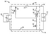
- FIG. 2is a schematic diagram of a battery circuit for an electric vehicle that employs a single resistor that provides both a pre-charge function and a heating function;
- FIG. 3is a schematic diagram of another battery circuit for an electric vehicle that employs a single resistor that provides both a pre-charge function and a heating function.
- the battery circuit of the inventionis described herein as being for an electric vehicle, including electric hybrid vehicles. However, as will be appreciated by those skilled in the art, the battery circuit may be applicable for other applications.
- FIG. 1is a schematic diagram of a known battery circuit 10 including a battery 12 and a battery disconnect unit (BDU) 14 .
- the battery 12can be any battery suitable for the purposes described herein, such as a nickel metal hydride battery, a lithium-ion battery, a lead-acid battery, etc.
- the battery 12includes a plurality of battery cells electrically coupled in series and/or in parallel to provide the desired high voltage for this particular application.
- the battery 12is electrically coupled to a high voltage bus shown here as a combined positive bus line 16 and negative bus line 18 .
- Various high voltage componentswould be electrical coupled to the bus lines 16 and 18 for the particular application.
- one of those componentsis a TPIM 20 that couples the high voltage on the bus lines 16 and 18 to an AC traction motor (not shown).
- Other high voltage electrical componentswould be coupled to the bus lines 16 and 18 , although not specifically shown.
- the electrical components that are coupled to the high voltage bus lines 16 and 18typically include a capacitor to filter bus noise, where capacitor 22 is provided in the TPIM 20 as an illustration of this.
- the positive bus line 16includes a positive battery contactor or switch 24 , such as a relay, and the negative bus line 18 includes a negative contactor or switch 26 , where the switches 24 and 26 selectively connect and disconnect the battery 12 to the high voltage bus on the vehicle in a manner that is well understood by those skilled in the art.
- a positive battery contactor or switch 24such as a relay
- the negative bus line 18includes a negative contactor or switch 26 , where the switches 24 and 26 selectively connect and disconnect the battery 12 to the high voltage bus on the vehicle in a manner that is well understood by those skilled in the art.
- the battery circuit 10also includes a pre-charge resistor 34 electrically coupled to the positive bus line 16 in a manner that allows it to by-pass the switch 24 when a heater switch 32 is closed.
- the pre-charge resistor 34can be selectively coupled to the positive bus line 16 by an FET switch 36 that receives a logic signal at its gate terminal through appropriate high voltage isolation electronics (not shown) to close the switch 36 .
- a high voltage blocking diode 38prevents current flow from the positive bus line 16 to the resistor 34 when the switch 24 is closed during operation of the system.
- the pre-charge resistor 34provides a load at system start-up when the capacitor 22 , and other capacitors, provide a direct short across the bus lines 16 and 18 to prevent damage to the capacitor 22 , the switches 24 and 26 , and other electrical components.
- the circuit 10includes a resistive electric heater 40 including a resistor 42 for this purpose that is electrically coupled to across the bus lines 16 and 18 when the heater switch 32 is closed.
- the resistor 42would typically have a significantly higher resistance than the pre-charge resistor 34 .
- An FET switch 30selectively turns on the heater 40 when it receives a signal at its gate terminal to close the switch 30 through suitable high voltage isolation circuitry (not shown), as is well understood by those skilled in the art.
- a fuse 28provides over current protection for the battery circuit elements.
- FIG. 2is a schematic diagram of a heater circuit 50 similar to the heater circuit 10 , where like elements are identified by the same reference number.
- the pre-charge resistor 34is eliminated and the resistor 42 provides both the heating function for raising the temperature of the battery 12 and the pre-charge function.
- the resistor 42would still be positioned within the cooling fluid of the thermal battery system to heat the cooling fluid when desired, but is also selectively used as a load to perform the pre-charging function.
- the switch 36would still be used to switch on the pre-charge function where it electrically couples the heater 40 to the positive bus line 16 as in the circuit 10 when the switch 32 is closed.
- the switch 30would still connect the heater 40 to the positive and negative bus lines 16 and 18 when the switch 32 is closed. Both of the switches 36 and 30 cannot be closed at the same time. If both heating and pre-charging were desired at the same time, then the pre-charge function would take precedent where the switch 30 would be open. This is because the pre-charge operation would be very quick, typically on the order of less than 300 milliseconds. Once the pre-charge operation was completed, then the switch 36 would be opened and the switch 30 would be closed to again provide the heating function, if desired.
- the resistance of the resistor 42is selected for the desired and proper heating, which would typically be a higher resistance than is necessary for the pre-charge function.
- the time frame for providing the pre-charge functioncould be increased to provide the proper pre-charging for the desired heating resistance.
- the resistance of the heater resistor 42could be reduced, which would reduce its heating capacity.
- the control of the switch 30 to provide the heatingis typically provided by a pulse width modulation (PWM) signal having a certain duty cycle. That duty cycle pulse could be decreased for the smaller resistance to provide the same of amount of heating.
- PWMpulse width modulation
- the heatercan be a two-stage heater.
- FIG. 3shows a schematic diagram of a heater circuit 60 similar to the heater circuit 50 , where like elements are identified by the same reference number.
- the heater 40is replaced with a two-stage heater 62 having a variable resistor 64 . Only a desired portion of the resistor 64 is used during the pre-charge operation and the entire resistor 64 is used during the heating operation so that the optimal resistance can be provided for the pre-charge operation and the heating operation.
- the number of resistors in the circuit 50By reducing the number of resistors in the circuit 50 , the number of components can be reduced which effects the cost and the weight of the system. Further, by providing a larger resistor for the pre-charging function, reliability of the pre-charging is increased.
Landscapes
- Engineering & Computer Science (AREA)
- General Chemical & Material Sciences (AREA)
- Manufacturing & Machinery (AREA)
- Chemical & Material Sciences (AREA)
- Chemical Kinetics & Catalysis (AREA)
- Electrochemistry (AREA)
- Sustainable Development (AREA)
- Life Sciences & Earth Sciences (AREA)
- Microelectronics & Electronic Packaging (AREA)
- Sustainable Energy (AREA)
- Power Engineering (AREA)
- Transportation (AREA)
- Mechanical Engineering (AREA)
- Physics & Mathematics (AREA)
- Electromagnetism (AREA)
- Secondary Cells (AREA)
- Electric Propulsion And Braking For Vehicles (AREA)
Abstract
Description
Claims (20)
Priority Applications (3)
| Application Number | Priority Date | Filing Date | Title |
|---|---|---|---|
| US12/853,695US8497031B2 (en) | 2010-08-10 | 2010-08-10 | Combined heating and pre-charging function and hardware for propulsion batteries |
| DE201110109198DE102011109198A1 (en) | 2010-08-10 | 2011-08-02 | COMBINED HEATING AND PRE-CHARGING FUNCTION AND HARDWARE FOR PROPULSION BATTERIES |
| CN201110228250.7ACN102377215B (en) | 2010-08-10 | 2011-08-10 | Combined heating and pre-charging function and hardware for propulsion batteries |
Applications Claiming Priority (1)
| Application Number | Priority Date | Filing Date | Title |
|---|---|---|---|
| US12/853,695US8497031B2 (en) | 2010-08-10 | 2010-08-10 | Combined heating and pre-charging function and hardware for propulsion batteries |
Publications (2)
| Publication Number | Publication Date |
|---|---|
| US20120040224A1 US20120040224A1 (en) | 2012-02-16 |
| US8497031B2true US8497031B2 (en) | 2013-07-30 |
Family
ID=45565054
Family Applications (1)
| Application Number | Title | Priority Date | Filing Date |
|---|---|---|---|
| US12/853,695Expired - Fee RelatedUS8497031B2 (en) | 2010-08-10 | 2010-08-10 | Combined heating and pre-charging function and hardware for propulsion batteries |
Country Status (3)
| Country | Link |
|---|---|
| US (1) | US8497031B2 (en) |
| CN (1) | CN102377215B (en) |
| DE (1) | DE102011109198A1 (en) |
Cited By (4)
| Publication number | Priority date | Publication date | Assignee | Title |
|---|---|---|---|---|
| US20150091377A1 (en)* | 2013-09-27 | 2015-04-02 | GM Global Technology Operations LLC | Distributed vehicle battery high-voltage bus systems and methods |
| US20150258901A1 (en)* | 2014-03-14 | 2015-09-17 | Hyundai Motor Company | Stable power supply device for high voltage battery system |
| EP3674128A1 (en)* | 2018-12-28 | 2020-07-01 | Delphi Automotive Systems Luxembourg SA | Electrical vehicle system to discharge capacitors |
| US11358471B2 (en) | 2018-12-28 | 2022-06-14 | Dr. Ing. H.C. F. Porsche Aktiengesellschaft | Electrical vehicle system |
Families Citing this family (26)
| Publication number | Priority date | Publication date | Assignee | Title |
|---|---|---|---|---|
| US8497031B2 (en)* | 2010-08-10 | 2013-07-30 | GM Global Technology Operations LLC | Combined heating and pre-charging function and hardware for propulsion batteries |
| US20120203404A1 (en)* | 2011-02-04 | 2012-08-09 | GM Global Technology Operations LLC | Method for heating hybrid powertrain components |
| JP5264949B2 (en)* | 2011-03-08 | 2013-08-14 | 本田技研工業株式会社 | Electric vehicle |
| US9096134B2 (en)* | 2012-01-24 | 2015-08-04 | GM Global Technology Operations LLC | Enhanced HV pre-charge heater diagnostic detection system for liquid cooled HV battery packs |
| US20130193920A1 (en)* | 2012-01-26 | 2013-08-01 | Lear Corporation | Apparatus and method of dual use resistor for battery disconnect |
| DE102013201296A1 (en) | 2012-01-26 | 2013-08-01 | Lear Corp. | Vehicle device for connection and disconnection of battery of e.g. electric car, has battery supercharger supplying part of direct current to resistor to perform battery heating operation if vehicle load operation is performed |
| DE102012205095A1 (en)* | 2012-03-29 | 2013-10-02 | Robert Bosch Gmbh | A method for heating energy storage cells of an energy storage device and heatable energy storage device |
| CN102769315A (en)* | 2012-07-19 | 2012-11-07 | 隆鑫通用动力股份有限公司 | Pre-charging control device for motor controller of electric vehicle and electric vehicle using pre-charging control device |
| CN105216632A (en)* | 2014-06-30 | 2016-01-06 | 观致汽车有限公司 | For Vehicular battery group management system and method |
| CN105336994B (en)* | 2014-07-17 | 2018-04-13 | 观致汽车有限公司 | For Vehicular battery group management system and method |
| KR101736475B1 (en)* | 2015-02-04 | 2017-05-16 | 한화테크윈 주식회사 | Electric vehicle |
| CN105416079B (en)* | 2015-11-24 | 2017-11-14 | 北京新能源汽车股份有限公司 | Vehicle and control circuit for on-vehicle battery |
| CN105449778B (en)* | 2015-12-31 | 2017-10-24 | 惠州市亿能电子有限公司 | A kind of charging control circuit and control method |
| CN106376104B (en)* | 2016-09-07 | 2020-12-08 | 合肥工业大学智能制造技术研究院 | Battery self-discharge heating circuit |
| US10476262B2 (en)* | 2017-03-24 | 2019-11-12 | Ford Global Technologies, Llc | Dual-bus battery precharge circuit |
| EP3401980A1 (en)* | 2017-05-08 | 2018-11-14 | Lithium Energy and Power GmbH & Co. KG | Battery module with reduced short circuit current |
| KR102196265B1 (en)* | 2017-06-13 | 2020-12-29 | 주식회사 엘지화학 | Method and system for controling temperature of a battery pack |
| CN107310417A (en)* | 2017-06-30 | 2017-11-03 | 北京长城华冠汽车科技股份有限公司 | Automobile, electrokinetic cell DC charging circuit and its charging method |
| CN109873558B (en)* | 2017-12-04 | 2020-07-14 | 中国船舶重工集团海装风电股份有限公司 | Converter pre-charging and heating circuit and control method thereof |
| CN110497806A (en)* | 2018-05-18 | 2019-11-26 | 王素蔚 | A zero-crossing open charging connection device |
| US11251637B2 (en) | 2018-12-04 | 2022-02-15 | Mobile Escapes, Llc | Mobile power system with multiple converters and related platforms and methods |
| US10873199B2 (en)* | 2018-12-28 | 2020-12-22 | Delphi Automotive Systems Luxembourg S.A. | Vehicle electrical system to charge capacitors |
| CN111516555B (en)* | 2020-04-26 | 2022-10-21 | 东风柳州汽车有限公司 | Temperature adjusting system and method for vehicle-mounted battery |
| CN112339567B (en)* | 2020-10-28 | 2022-03-25 | 睿驰电装(大连)电动系统有限公司 | Pre-charging control method and device based on load and electronic equipment |
| DE102021133998B3 (en) | 2021-12-21 | 2023-01-26 | Dr. Ing. H.C. F. Porsche Aktiengesellschaft | Circuit arrangement for an at least partially electrically driven motor vehicle and motor vehicle |
| CN118573156B (en)* | 2024-07-31 | 2024-12-10 | 比亚迪股份有限公司 | Pulse circuit, control method and vehicle |
Citations (15)
| Publication number | Priority date | Publication date | Assignee | Title |
|---|---|---|---|---|
| US4346336A (en)* | 1980-11-17 | 1982-08-24 | Frezzolini Electronics, Inc. | Battery control system |
| US5825155A (en)* | 1993-08-09 | 1998-10-20 | Kabushiki Kaisha Toshiba | Battery set structure and charge/ discharge control apparatus for lithium-ion battery |
| US20110057586A1 (en)* | 2006-07-17 | 2011-03-10 | O2Micro International Limited | Monitoring battery cell voltage |
| US20110121789A1 (en)* | 2009-11-20 | 2011-05-26 | Jong-Woon Yang | Battery pack and method of controlling charging of battery pack |
| US20110250484A1 (en)* | 2010-04-12 | 2011-10-13 | Changzhou Globe Tools Co., Ltd. | Battery Pack and Combination of the Battery Pack and an Electric Device |
| US20120025780A1 (en)* | 2010-07-30 | 2012-02-02 | Byd Company Limited | Heating circuits and methods based on battery discharging and charging using resonance components in series and freewheeling circuit components |
| US20120034507A1 (en)* | 2009-04-28 | 2012-02-09 | Hitachi Vehicle Energy, Ltd. | Electricity Storage Module and Electricity Storage Device Equipped Therewith |
| US20120040224A1 (en)* | 2010-08-10 | 2012-02-16 | Gm Global Technology Operations, Inc. | Combined heating and pre-charging function and hardware for propulsion batteries |
| US8148003B2 (en)* | 2006-04-12 | 2012-04-03 | Mitsubishi Electric Corporation | Power storage apparatus |
| US20120141857A1 (en)* | 2010-04-28 | 2012-06-07 | Takuya Nakashima | Battery module |
| US20120214041A1 (en)* | 2009-09-30 | 2012-08-23 | Hitachi Vehicle Energy, Ltd. | Electricity storage module |
| US20130004804A1 (en)* | 2011-06-30 | 2013-01-03 | Lg Chem Ltd. | Heating system for a battery module and method of heating the battery module |
| US20130004803A1 (en)* | 2011-06-30 | 2013-01-03 | Lg Chem Ltd. | Heating system for a battery module and method of heating the battery module |
| US20130004802A1 (en)* | 2011-06-30 | 2013-01-03 | Lg Chem Ltd. | Heating system for a battery module and method of heating the battery module |
| US20130004805A1 (en)* | 2011-06-30 | 2013-01-03 | Lg Chem Ltd. | Heating system for a battery module and method of heating the battery module |
Family Cites Families (4)
| Publication number | Priority date | Publication date | Assignee | Title |
|---|---|---|---|---|
| TW595830U (en)* | 2003-05-21 | 2004-06-21 | Iwei Technology Co Ltd | Structure improvement of polarity-less charger |
| JP5157193B2 (en)* | 2007-02-26 | 2013-03-06 | 日産自動車株式会社 | Control device for vehicle starting system |
| DE102007047713A1 (en)* | 2007-10-05 | 2009-04-09 | Robert Bosch Gmbh | Method for discharging the high-voltage network |
| CN201181852Y (en)* | 2008-04-14 | 2009-01-14 | 荣及峰 | Box type charging station for electric automobile |
- 2010
- 2010-08-10USUS12/853,695patent/US8497031B2/ennot_activeExpired - Fee Related
- 2011
- 2011-08-02DEDE201110109198patent/DE102011109198A1/ennot_activeWithdrawn
- 2011-08-10CNCN201110228250.7Apatent/CN102377215B/ennot_activeExpired - Fee Related
Patent Citations (17)
| Publication number | Priority date | Publication date | Assignee | Title |
|---|---|---|---|---|
| US4346336A (en)* | 1980-11-17 | 1982-08-24 | Frezzolini Electronics, Inc. | Battery control system |
| US5825155A (en)* | 1993-08-09 | 1998-10-20 | Kabushiki Kaisha Toshiba | Battery set structure and charge/ discharge control apparatus for lithium-ion battery |
| US8148003B2 (en)* | 2006-04-12 | 2012-04-03 | Mitsubishi Electric Corporation | Power storage apparatus |
| US20110057586A1 (en)* | 2006-07-17 | 2011-03-10 | O2Micro International Limited | Monitoring battery cell voltage |
| US20120034507A1 (en)* | 2009-04-28 | 2012-02-09 | Hitachi Vehicle Energy, Ltd. | Electricity Storage Module and Electricity Storage Device Equipped Therewith |
| US20120214041A1 (en)* | 2009-09-30 | 2012-08-23 | Hitachi Vehicle Energy, Ltd. | Electricity storage module |
| US20110121789A1 (en)* | 2009-11-20 | 2011-05-26 | Jong-Woon Yang | Battery pack and method of controlling charging of battery pack |
| US20110250484A1 (en)* | 2010-04-12 | 2011-10-13 | Changzhou Globe Tools Co., Ltd. | Battery Pack and Combination of the Battery Pack and an Electric Device |
| US20120141857A1 (en)* | 2010-04-28 | 2012-06-07 | Takuya Nakashima | Battery module |
| US20120031890A1 (en)* | 2010-07-30 | 2012-02-09 | Byd Company Limited | Battery heating circuits and methods with resonance components in series using voltage inversion and freewheeling circuit components |
| US20120032642A1 (en)* | 2010-07-30 | 2012-02-09 | Byd Company Limited | Battery heating circuits and methods with resonance components in series using voltage inversion based on predetermined conditions |
| US20120025780A1 (en)* | 2010-07-30 | 2012-02-02 | Byd Company Limited | Heating circuits and methods based on battery discharging and charging using resonance components in series and freewheeling circuit components |
| US20120040224A1 (en)* | 2010-08-10 | 2012-02-16 | Gm Global Technology Operations, Inc. | Combined heating and pre-charging function and hardware for propulsion batteries |
| US20130004804A1 (en)* | 2011-06-30 | 2013-01-03 | Lg Chem Ltd. | Heating system for a battery module and method of heating the battery module |
| US20130004803A1 (en)* | 2011-06-30 | 2013-01-03 | Lg Chem Ltd. | Heating system for a battery module and method of heating the battery module |
| US20130004802A1 (en)* | 2011-06-30 | 2013-01-03 | Lg Chem Ltd. | Heating system for a battery module and method of heating the battery module |
| US20130004805A1 (en)* | 2011-06-30 | 2013-01-03 | Lg Chem Ltd. | Heating system for a battery module and method of heating the battery module |
Cited By (7)
| Publication number | Priority date | Publication date | Assignee | Title |
|---|---|---|---|---|
| US20150091377A1 (en)* | 2013-09-27 | 2015-04-02 | GM Global Technology Operations LLC | Distributed vehicle battery high-voltage bus systems and methods |
| US9802558B2 (en)* | 2013-09-27 | 2017-10-31 | GM Global Technology Operations LLC | Distributed vehicle battery high-voltage bus systems and methods |
| US20150258901A1 (en)* | 2014-03-14 | 2015-09-17 | Hyundai Motor Company | Stable power supply device for high voltage battery system |
| US9738164B2 (en)* | 2014-03-14 | 2017-08-22 | Hyundai Motor Company | Stable power supply device for high voltage battery system |
| EP3674128A1 (en)* | 2018-12-28 | 2020-07-01 | Delphi Automotive Systems Luxembourg SA | Electrical vehicle system to discharge capacitors |
| US11101671B2 (en) | 2018-12-28 | 2021-08-24 | Dr. Ing. H.C. F. Porsche Aktiengesellschaft | Electrical vehicle system to discharge capacitors |
| US11358471B2 (en) | 2018-12-28 | 2022-06-14 | Dr. Ing. H.C. F. Porsche Aktiengesellschaft | Electrical vehicle system |
Also Published As
| Publication number | Publication date |
|---|---|
| US20120040224A1 (en) | 2012-02-16 |
| DE102011109198A1 (en) | 2012-03-01 |
| CN102377215B (en) | 2015-04-01 |
| CN102377215A (en) | 2012-03-14 |
Similar Documents
| Publication | Publication Date | Title |
|---|---|---|
| US8497031B2 (en) | Combined heating and pre-charging function and hardware for propulsion batteries | |
| US8471529B2 (en) | Battery fault tolerant architecture for cell failure modes parallel bypass circuit | |
| US9024586B2 (en) | Battery fault tolerant architecture for cell failure modes series bypass circuit | |
| US9096134B2 (en) | Enhanced HV pre-charge heater diagnostic detection system for liquid cooled HV battery packs | |
| US20130234508A1 (en) | Apparatus for use in an electrical drive system, and method for operating an apparatus of this kind | |
| US8803486B2 (en) | Power supply device | |
| US10913361B2 (en) | Battery temperature control system and method | |
| US20170264136A1 (en) | Multiple Energy Accumulator System for Motor Vehicle Electrical Systems | |
| US9855904B2 (en) | Coupling store device for a motor vehicle | |
| US20210175485A1 (en) | System and method for operating a dual battery system | |
| US8937400B2 (en) | Power supply apparatus for vehicle | |
| EP3232049B1 (en) | Automobile starting control system and automobile | |
| CN107710548B (en) | Battery system and method for bi-directional current control | |
| US12246617B2 (en) | Vehicle traction battery circuit and control system | |
| CN108352714B (en) | Power supply unit and battery unit | |
| KR102344505B1 (en) | Power source connection apparatus and method thereof | |
| US20150102763A1 (en) | System and method for desulfation of a lead-acid battery | |
| JP2015179613A (en) | Vehicle power supply system | |
| Medora et al. | Battery management for hybrid electric vehicles using supercapacitors as a supplementary energy storage system | |
| CN110816311B (en) | Method for operating a battery system and electric vehicle | |
| US20250128614A1 (en) | Power supply device | |
| US11951871B2 (en) | Multi-voltage storage system for an at least partly electrically driven vehicle | |
| US20240409130A1 (en) | Rail vehicle traction system and associated rail vehicle | |
| KR102637753B1 (en) | Smart power relay assembly with low voltage relay and fail safety system using the smart power relay assembly with low voltage relay and fail safety method uising the fail safety system |
Legal Events
| Date | Code | Title | Description |
|---|---|---|---|
| AS | Assignment | Owner name:GM GLOBAL TECHNOLOGY OPERATIONS, INC., MICHIGAN Free format text:ASSIGNMENT OF ASSIGNORS INTEREST;ASSIGNORS:REISCHMANN, MARC;ANDRES, PETER;SIGNING DATES FROM 20100722 TO 20100809;REEL/FRAME:024817/0963 | |
| AS | Assignment | Owner name:WILMINGTON TRUST COMPANY, DELAWARE Free format text:SECURITY AGREEMENT;ASSIGNOR:GM GLOBAL TECHNOLOGY OPERATIONS, INC.;REEL/FRAME:025327/0156 Effective date:20101027 | |
| AS | Assignment | Owner name:GM GLOBAL TECHNOLOGY OPERATIONS LLC, MICHIGAN Free format text:CHANGE OF NAME;ASSIGNOR:GM GLOBAL TECHNOLOGY OPERATIONS, INC.;REEL/FRAME:025781/0333 Effective date:20101202 | |
| FEPP | Fee payment procedure | Free format text:PAYOR NUMBER ASSIGNED (ORIGINAL EVENT CODE: ASPN); ENTITY STATUS OF PATENT OWNER: LARGE ENTITY | |
| STCF | Information on status: patent grant | Free format text:PATENTED CASE | |
| AS | Assignment | Owner name:GM GLOBAL TECHNOLOGY OPERATIONS LLC, MICHIGAN Free format text:RELEASE BY SECURED PARTY;ASSIGNOR:WILMINGTON TRUST COMPANY;REEL/FRAME:034287/0159 Effective date:20141017 | |
| FPAY | Fee payment | Year of fee payment:4 | |
| FEPP | Fee payment procedure | Free format text:MAINTENANCE FEE REMINDER MAILED (ORIGINAL EVENT CODE: REM.); ENTITY STATUS OF PATENT OWNER: LARGE ENTITY | |
| LAPS | Lapse for failure to pay maintenance fees | Free format text:PATENT EXPIRED FOR FAILURE TO PAY MAINTENANCE FEES (ORIGINAL EVENT CODE: EXP.); ENTITY STATUS OF PATENT OWNER: LARGE ENTITY | |
| STCH | Information on status: patent discontinuation | Free format text:PATENT EXPIRED DUE TO NONPAYMENT OF MAINTENANCE FEES UNDER 37 CFR 1.362 | |
| FP | Lapsed due to failure to pay maintenance fee | Effective date:20210730 |