US8496697B2 - Stent graft - Google Patents
Stent graftDownload PDFInfo
- Publication number
- US8496697B2 US8496697B2US13/057,261US200913057261AUS8496697B2US 8496697 B2US8496697 B2US 8496697B2US 200913057261 AUS200913057261 AUS 200913057261AUS 8496697 B2US8496697 B2US 8496697B2
- Authority
- US
- United States
- Prior art keywords
- stent
- strut
- patterns
- wall structure
- connectors
- Prior art date
- Legal status (The legal status is an assumption and is not a legal conclusion. Google has not performed a legal analysis and makes no representation as to the accuracy of the status listed.)
- Active, expires
Links
Images


Classifications
- A—HUMAN NECESSITIES
- A61—MEDICAL OR VETERINARY SCIENCE; HYGIENE
- A61F—FILTERS IMPLANTABLE INTO BLOOD VESSELS; PROSTHESES; DEVICES PROVIDING PATENCY TO, OR PREVENTING COLLAPSING OF, TUBULAR STRUCTURES OF THE BODY, e.g. STENTS; ORTHOPAEDIC, NURSING OR CONTRACEPTIVE DEVICES; FOMENTATION; TREATMENT OR PROTECTION OF EYES OR EARS; BANDAGES, DRESSINGS OR ABSORBENT PADS; FIRST-AID KITS
- A61F2/00—Filters implantable into blood vessels; Prostheses, i.e. artificial substitutes or replacements for parts of the body; Appliances for connecting them with the body; Devices providing patency to, or preventing collapsing of, tubular structures of the body, e.g. stents
- A61F2/02—Prostheses implantable into the body
- A61F2/04—Hollow or tubular parts of organs, e.g. bladders, tracheae, bronchi or bile ducts
- A61F2/06—Blood vessels
- A61F2/07—Stent-grafts
- A—HUMAN NECESSITIES
- A61—MEDICAL OR VETERINARY SCIENCE; HYGIENE
- A61F—FILTERS IMPLANTABLE INTO BLOOD VESSELS; PROSTHESES; DEVICES PROVIDING PATENCY TO, OR PREVENTING COLLAPSING OF, TUBULAR STRUCTURES OF THE BODY, e.g. STENTS; ORTHOPAEDIC, NURSING OR CONTRACEPTIVE DEVICES; FOMENTATION; TREATMENT OR PROTECTION OF EYES OR EARS; BANDAGES, DRESSINGS OR ABSORBENT PADS; FIRST-AID KITS
- A61F2/00—Filters implantable into blood vessels; Prostheses, i.e. artificial substitutes or replacements for parts of the body; Appliances for connecting them with the body; Devices providing patency to, or preventing collapsing of, tubular structures of the body, e.g. stents
- A61F2/82—Devices providing patency to, or preventing collapsing of, tubular structures of the body, e.g. stents
- A61F2/86—Stents in a form characterised by the wire-like elements; Stents in the form characterised by a net-like or mesh-like structure
- A61F2/90—Stents in a form characterised by the wire-like elements; Stents in the form characterised by a net-like or mesh-like structure characterised by a net-like or mesh-like structure
- A61F2/91—Stents in a form characterised by the wire-like elements; Stents in the form characterised by a net-like or mesh-like structure characterised by a net-like or mesh-like structure made from perforated sheets or tubes, e.g. perforated by laser cuts or etched holes
- A61F2/915—Stents in a form characterised by the wire-like elements; Stents in the form characterised by a net-like or mesh-like structure characterised by a net-like or mesh-like structure made from perforated sheets or tubes, e.g. perforated by laser cuts or etched holes with bands having a meander structure, adjacent bands being connected to each other
- A—HUMAN NECESSITIES
- A61—MEDICAL OR VETERINARY SCIENCE; HYGIENE
- A61F—FILTERS IMPLANTABLE INTO BLOOD VESSELS; PROSTHESES; DEVICES PROVIDING PATENCY TO, OR PREVENTING COLLAPSING OF, TUBULAR STRUCTURES OF THE BODY, e.g. STENTS; ORTHOPAEDIC, NURSING OR CONTRACEPTIVE DEVICES; FOMENTATION; TREATMENT OR PROTECTION OF EYES OR EARS; BANDAGES, DRESSINGS OR ABSORBENT PADS; FIRST-AID KITS
- A61F2/00—Filters implantable into blood vessels; Prostheses, i.e. artificial substitutes or replacements for parts of the body; Appliances for connecting them with the body; Devices providing patency to, or preventing collapsing of, tubular structures of the body, e.g. stents
- A61F2/82—Devices providing patency to, or preventing collapsing of, tubular structures of the body, e.g. stents
- A61F2/852—Two or more distinct overlapping stents
- A—HUMAN NECESSITIES
- A61—MEDICAL OR VETERINARY SCIENCE; HYGIENE
- A61F—FILTERS IMPLANTABLE INTO BLOOD VESSELS; PROSTHESES; DEVICES PROVIDING PATENCY TO, OR PREVENTING COLLAPSING OF, TUBULAR STRUCTURES OF THE BODY, e.g. STENTS; ORTHOPAEDIC, NURSING OR CONTRACEPTIVE DEVICES; FOMENTATION; TREATMENT OR PROTECTION OF EYES OR EARS; BANDAGES, DRESSINGS OR ABSORBENT PADS; FIRST-AID KITS
- A61F2/00—Filters implantable into blood vessels; Prostheses, i.e. artificial substitutes or replacements for parts of the body; Appliances for connecting them with the body; Devices providing patency to, or preventing collapsing of, tubular structures of the body, e.g. stents
- A61F2/82—Devices providing patency to, or preventing collapsing of, tubular structures of the body, e.g. stents
- A61F2/86—Stents in a form characterised by the wire-like elements; Stents in the form characterised by a net-like or mesh-like structure
- A61F2/89—Stents in a form characterised by the wire-like elements; Stents in the form characterised by a net-like or mesh-like structure the wire-like elements comprising two or more adjacent rings flexibly connected by separate members
- A—HUMAN NECESSITIES
- A61—MEDICAL OR VETERINARY SCIENCE; HYGIENE
- A61F—FILTERS IMPLANTABLE INTO BLOOD VESSELS; PROSTHESES; DEVICES PROVIDING PATENCY TO, OR PREVENTING COLLAPSING OF, TUBULAR STRUCTURES OF THE BODY, e.g. STENTS; ORTHOPAEDIC, NURSING OR CONTRACEPTIVE DEVICES; FOMENTATION; TREATMENT OR PROTECTION OF EYES OR EARS; BANDAGES, DRESSINGS OR ABSORBENT PADS; FIRST-AID KITS
- A61F2/00—Filters implantable into blood vessels; Prostheses, i.e. artificial substitutes or replacements for parts of the body; Appliances for connecting them with the body; Devices providing patency to, or preventing collapsing of, tubular structures of the body, e.g. stents
- A61F2/02—Prostheses implantable into the body
- A61F2/04—Hollow or tubular parts of organs, e.g. bladders, tracheae, bronchi or bile ducts
- A61F2/06—Blood vessels
- A61F2/07—Stent-grafts
- A61F2002/072—Encapsulated stents, e.g. wire or whole stent embedded in lining
- A—HUMAN NECESSITIES
- A61—MEDICAL OR VETERINARY SCIENCE; HYGIENE
- A61F—FILTERS IMPLANTABLE INTO BLOOD VESSELS; PROSTHESES; DEVICES PROVIDING PATENCY TO, OR PREVENTING COLLAPSING OF, TUBULAR STRUCTURES OF THE BODY, e.g. STENTS; ORTHOPAEDIC, NURSING OR CONTRACEPTIVE DEVICES; FOMENTATION; TREATMENT OR PROTECTION OF EYES OR EARS; BANDAGES, DRESSINGS OR ABSORBENT PADS; FIRST-AID KITS
- A61F2/00—Filters implantable into blood vessels; Prostheses, i.e. artificial substitutes or replacements for parts of the body; Appliances for connecting them with the body; Devices providing patency to, or preventing collapsing of, tubular structures of the body, e.g. stents
- A61F2/82—Devices providing patency to, or preventing collapsing of, tubular structures of the body, e.g. stents
- A61F2/86—Stents in a form characterised by the wire-like elements; Stents in the form characterised by a net-like or mesh-like structure
- A61F2/90—Stents in a form characterised by the wire-like elements; Stents in the form characterised by a net-like or mesh-like structure characterised by a net-like or mesh-like structure
- A61F2/91—Stents in a form characterised by the wire-like elements; Stents in the form characterised by a net-like or mesh-like structure characterised by a net-like or mesh-like structure made from perforated sheets or tubes, e.g. perforated by laser cuts or etched holes
- A61F2/915—Stents in a form characterised by the wire-like elements; Stents in the form characterised by a net-like or mesh-like structure characterised by a net-like or mesh-like structure made from perforated sheets or tubes, e.g. perforated by laser cuts or etched holes with bands having a meander structure, adjacent bands being connected to each other
- A61F2002/9155—Adjacent bands being connected to each other
- A61F2002/91575—Adjacent bands being connected to each other connected peak to trough
- A—HUMAN NECESSITIES
- A61—MEDICAL OR VETERINARY SCIENCE; HYGIENE
- A61F—FILTERS IMPLANTABLE INTO BLOOD VESSELS; PROSTHESES; DEVICES PROVIDING PATENCY TO, OR PREVENTING COLLAPSING OF, TUBULAR STRUCTURES OF THE BODY, e.g. STENTS; ORTHOPAEDIC, NURSING OR CONTRACEPTIVE DEVICES; FOMENTATION; TREATMENT OR PROTECTION OF EYES OR EARS; BANDAGES, DRESSINGS OR ABSORBENT PADS; FIRST-AID KITS
- A61F2220/00—Fixations or connections for prostheses classified in groups A61F2/00 - A61F2/26 or A61F2/82 or A61F9/00 or A61F11/00 or subgroups thereof
- A61F2220/0025—Connections or couplings between prosthetic parts, e.g. between modular parts; Connecting elements
- A61F2220/0058—Connections or couplings between prosthetic parts, e.g. between modular parts; Connecting elements soldered or brazed or welded
- A—HUMAN NECESSITIES
- A61—MEDICAL OR VETERINARY SCIENCE; HYGIENE
- A61F—FILTERS IMPLANTABLE INTO BLOOD VESSELS; PROSTHESES; DEVICES PROVIDING PATENCY TO, OR PREVENTING COLLAPSING OF, TUBULAR STRUCTURES OF THE BODY, e.g. STENTS; ORTHOPAEDIC, NURSING OR CONTRACEPTIVE DEVICES; FOMENTATION; TREATMENT OR PROTECTION OF EYES OR EARS; BANDAGES, DRESSINGS OR ABSORBENT PADS; FIRST-AID KITS
- A61F2250/00—Special features of prostheses classified in groups A61F2/00 - A61F2/26 or A61F2/82 or A61F9/00 or A61F11/00 or subgroups thereof
- A61F2250/0058—Additional features; Implant or prostheses properties not otherwise provided for
- A61F2250/006—Additional features; Implant or prostheses properties not otherwise provided for modular
- A61F2250/0063—Nested prosthetic parts
Definitions
- the present inventionrelates to a stent graft.
- Stent graftsgenerally comprise an inner stent and an outer stent using similar wall structures including the same strut-patterns and a flexible membrane or stretchable material layer interposed between the inner and outer stent.
- the inner stentWhen the balloon of the catheter is inflated the inner stent is less expanded than the outer stent and therefore physically exhibits a bigger recoil force compared to the more expanded outer stent.
- the smaller radially acting contact force of the expanded inner stent onto the outer stentdeteriorates the desired connecting performance of the stent-graft.
- stent-grafts having thinner walls to be more flexibleare often damaged or destroyed during welding to fix both stents to one another
- the stent-graftincludes an inner stent having a wall structure including juxtaposed strut-patterns with interconnected struts and connectors connecting the strut-patterns, the wall structure of the inner stent having a predetermined length, an outer stent coaxially arranged around the inner stent and having a wall structure including juxtaposed strut-patterns with interconnected struts and connectors connecting the strut-patterns, the wall structure of the outer stent having a predetermined length and a flexible stretchable material layer arranged between the inner stent and the outer stent, wherein the wall structure of the inner stent has a design differing from the design of the wall structure of the outer stent and wherein the length of the inner stent is equal to the length of the outer stent.
- the struts of the inner stentare formed shorter than the struts of the outer stent and the connectors of the inner stent are longer than the connectors of the outer stent.
- the struts of the inner stentare formed shorter than the struts of the outer stent and the connectors of the inner stent have the same length as the connectors of the outer stent and the inner stent has at least one additional strut pattern.
- the struts of the inner stentare formed shorter than the struts of the outer stent and the straight connectors of the inner stent are shorter than the straight connectors of the outer stent, the s-shaped connectors of the inner and outer stent having the same length and width, and the inner stent has at least one additional strut pattern.
- the crown ends of the outer and inner stentsinclude a welding zone having a welding point to fix the outer and inner stents to one another.
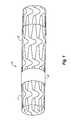
- FIG. 1shows an enlarged perspective view of a common stent-graph
- FIG. 2Ashows an enlarged plan view of a wall structure of an outer stent of the stent-graft according to the present invention
- FIG. 2Bshows an enlarged plan view of a wall structure of an inner stent of the stent-graft according to the present invention.
- FIG. 3Ashows an enlarged view of a further embodiment of a wall structure of the outer stent of the stent-graft according to the present invention.
- FIG. 3Bshows an enlarged view of a further embodiment of a wall structure of the inner stent of the stent-graft according to the present invention.
- FIG. 4shows an enlarged view of a further embodiment of a welding zone at the crown ends of the outer and inner stents of the stent-graft according to the present invention.
- FIG. 1shows an enlarged perspective view of a stent-graph 10 .
- An inner stent 11is connected to an outer stent 28 and of a flexible stretchable material layer 45 is disposed therebetween.
- the inner stent 11 and the outer stent 28each comprise a design of the wall structure which is different from each other.
- FIG. 2Ashows an enlarged plan view of the wall structure 34 of the outer stent 28 of the stent-graft 10 according to the present invention having a predetermined length L 2 .
- the design of the wall structure 34 of the outer stent 28includes five juxtaposed strut patterns 29 - 33 with interconnected struts 35 , 36 and connectors 37 - 44 connecting the strut patterns 29 - 33 .
- FIG. 2Bshows an enlarged plan view of the wall structure 12 of the inner stent 11 of the stent-graft 10 according to the present invention having a predetermined length L 1 which is equally long as the predetermined length L 2 of the outer stent 28 .
- the design of the wall structure 12 of the inner stent 11includes five juxtaposed strut patterns 13 - 17 with interconnected struts 18 , 19 and connectors 20 - 27 connecting the strut patterns 13 - 17 .
- the design of the wall structure 12differs from the design of the wall structure 34 in that shorter strut patterns 13 - 17 and longer connectors 20 - 27 are provided connecting the strut patterns 13 - 17 to define the same overall length L 1 as the length L 2 of the outer stent 28 illustrated in FIG. 2A .
- the struts 18 , 19 of the inner stent 11are shorter than the struts 35 , 36 of the outer stent 34 .
- the connectors 20 - 27 of the inner stent 11have the same length as the connectors of the outer stent 28 and the inner stent 11 has at least one additional strut pattern to define the same overall length L 1 as the length L 2 of the outer stent 28 .
- the inner stent 11having a different stent design either with shorter struts and slightly longer connectors 20 - 27 or at least one additional strut pattern along the predetermined length L 1 being equal to L 2 of the outer stent the radial connecting force of the inner stent 11 is increased during expansion and both stents 11 , 28 are pressed stronger to one another. Furthermore, the resultant difference in foreshortening as a result of the differing expansion of the inner and outer stents 11 , 28 of the stent-graft 10 of the present invention is favorably compensated.
- FIG. 3Ashows an enlarged plan view of the wall structure 67 of the outer stent 49 of the stent-graft 10 according to the present invention having a predetermined length L 3 which is equally long as the predetermined length L 4 of the inner stent 99 depicted in FIG. 3B .
- the design of the wall structure 67 of the outer stent 49includes thirteen juxtaposed strut patterns 50 - 62 with interconnected struts 68 , 69 and straight connectors 63 , 64 connecting the strut patterns 50 , 51 as well as the strut patterns ( 61 , 62 ).
- the strut patterns 52 to 60are interconnected with s-shaped connectors 65 , 66 .
- FIG. 3Bshows an enlarged plan view of the wall structure 88 of the inner stent 99 of the stent-graft 10 according to the present invention having a predetermined length L 4 which is equally long as the predetermined length L 3 of the outer stent 49 of FIG. 3A .
- the design of the wall structure 88 of the inner stent 99includes fourteen juxtaposed strut patterns ( 70 - 83 ) with interconnected struts ( 89 , 90 ) and straight connectors ( 84 - 85 ) connecting the strut patterns ( 70 - 71 ) as well as the strut patterns ( 82 - 83 ).
- the strut patterns ( 72 - 81 )are interconnected with s-shaped connectors 86 , 87 having the same length and width as the s-shaped connectors ( 65 , 66 ).
- This alternative embodiment(having a stent design with an increased number of shorter struts and slightly shorter straight connectors 84 , 85 , 91 , 92 between the adjacent first two and last two strut patterns 70 , 71 ; 82 , 83 and at least one additional strut pattern along the predetermined length L 4 being equal to L 3 of the outer stent results in an increased radial connecting force of the inner stent 99 during expansion and both stents 49 , 99 are pressed stronger to one another.
- FIG. 4shows an enlarged view of a further embodiment of the stent-graft 10 having a welding zone 102 at a crown end 100 of the outer stent 49 and a crown end 101 of the inner stent 99 comprising a welding point 103 which fixes both stents 49 , 99 to one another.
- FIGS. 1 to 3BIn addition to the written disclosure reference is herewith made explicitly to the disclosure of the invention in FIGS. 1 to 3B .
Landscapes
- Health & Medical Sciences (AREA)
- Engineering & Computer Science (AREA)
- Biomedical Technology (AREA)
- Heart & Thoracic Surgery (AREA)
- Life Sciences & Earth Sciences (AREA)
- Cardiology (AREA)
- Oral & Maxillofacial Surgery (AREA)
- Transplantation (AREA)
- Veterinary Medicine (AREA)
- Vascular Medicine (AREA)
- Public Health (AREA)
- Animal Behavior & Ethology (AREA)
- General Health & Medical Sciences (AREA)
- Optics & Photonics (AREA)
- Physics & Mathematics (AREA)
- Gastroenterology & Hepatology (AREA)
- Pulmonology (AREA)
- Prostheses (AREA)
Abstract
Description
Claims (8)
Applications Claiming Priority (4)
| Application Number | Priority Date | Filing Date | Title |
|---|---|---|---|
| EP08013947 | 2008-08-04 | ||
| EP08013947.0 | 2008-08-04 | ||
| EP08013947.0AEP2151217B1 (en) | 2008-08-04 | 2008-08-04 | Stent graft |
| PCT/EP2009/003529WO2010015291A1 (en) | 2008-08-04 | 2009-05-18 | Stent graft |
Related Parent Applications (1)
| Application Number | Title | Priority Date | Filing Date |
|---|---|---|---|
| PCT/EP2009/003529A-371-Of-InternationalWO2010015291A1 (en) | 2008-08-04 | 2009-05-18 | Stent graft |
Related Child Applications (1)
| Application Number | Title | Priority Date | Filing Date |
|---|---|---|---|
| US13/942,215DivisionUS9398947B2 (en) | 2008-08-04 | 2013-07-15 | Stent graft |
Publications (2)
| Publication Number | Publication Date |
|---|---|
| US20110213455A1 US20110213455A1 (en) | 2011-09-01 |
| US8496697B2true US8496697B2 (en) | 2013-07-30 |
Family
ID=40020209
Family Applications (2)
| Application Number | Title | Priority Date | Filing Date |
|---|---|---|---|
| US13/057,261Active2029-11-10US8496697B2 (en) | 2008-08-04 | 2009-05-18 | Stent graft |
| US13/942,215Active2030-02-20US9398947B2 (en) | 2008-08-04 | 2013-07-15 | Stent graft |
Family Applications After (1)
| Application Number | Title | Priority Date | Filing Date |
|---|---|---|---|
| US13/942,215Active2030-02-20US9398947B2 (en) | 2008-08-04 | 2013-07-15 | Stent graft |
Country Status (5)
| Country | Link |
|---|---|
| US (2) | US8496697B2 (en) |
| EP (1) | EP2151217B1 (en) |
| ES (1) | ES2837351T3 (en) |
| PL (1) | PL2151217T3 (en) |
| WO (1) | WO2010015291A1 (en) |
Cited By (3)
| Publication number | Priority date | Publication date | Assignee | Title |
|---|---|---|---|---|
| US9398947B2 (en) | 2008-08-04 | 2016-07-26 | Abbott Laboratories Vascular Enterprises Limited | Stent graft |
| US20190133795A1 (en)* | 2017-11-03 | 2019-05-09 | Covidien Lp | Meshes, devices and methods for treating vascular defects |
| US20210298929A1 (en)* | 2017-02-21 | 2021-09-30 | Silk Road Medical, Inc. | Vascular implant |
Families Citing this family (15)
| Publication number | Priority date | Publication date | Assignee | Title |
|---|---|---|---|---|
| DE102011115902B4 (en) | 2010-12-22 | 2021-07-01 | Bentley Innomed Gmbh | Stent-graft and its use |
| EP2559400A1 (en)* | 2011-08-19 | 2013-02-20 | Abbott Laboratories Vascular Enterprises Limited | Stent graft with alternating rings |
| DE102012001996A1 (en) | 2012-02-03 | 2013-08-08 | Bentley Surgical Gmbh | Balloon-expandable stent-graft for connecting stent and membrane for treatment of blood vessels, has spring tongues resiliently movable against web course, where hole membrane is sandwiched between spring tongues and web loops |
| US9629735B2 (en) | 2012-11-16 | 2017-04-25 | W. L. Gore & Associates, Inc. | Flexible endoluminal device |
| US9180031B2 (en) | 2013-03-15 | 2015-11-10 | Covidien Lp | Stent with varying radius between struts |
| US9259335B2 (en) | 2013-03-15 | 2016-02-16 | Covidien Lp | Stent |
| US20150105852A1 (en)* | 2013-10-16 | 2015-04-16 | Covidien Lp | Vascular Stent |
| WO2015098443A1 (en)* | 2013-12-25 | 2015-07-02 | 株式会社 京都医療設計 | Vascular stent |
| CN104939947A (en)* | 2014-03-26 | 2015-09-30 | 上海市第六人民医院 | Brain covered stent with endothelial progenitor cell capture function |
| KR101602389B1 (en)* | 2014-05-13 | 2016-03-10 | 주식회사 엠아이텍 | Stent and making method thereof |
| DE102015106052B4 (en) | 2015-04-21 | 2018-03-01 | Nikola Obradovic | Stent graft |
| DE102015115891A1 (en) | 2015-09-21 | 2017-03-23 | Bentley Innomed Gmbh | Stent graft |
| WO2019213120A1 (en) | 2018-05-02 | 2019-11-07 | W. L. Gore & Associates, Inc. | Expansion members for implantable devices and associated systems and methods |
| EP3595589B1 (en) | 2018-05-21 | 2024-10-09 | Aran Biomedical Teoranta | Insertable medical devices with low profile composite coverings |
| BR202020020329U2 (en)* | 2020-10-02 | 2022-04-19 | Braile Biomédica Indústria Comércio E Representações Ltda. | Constructive arrangement introduced in endoprosthesis |
Citations (7)
| Publication number | Priority date | Publication date | Assignee | Title |
|---|---|---|---|---|
| US5667523A (en)* | 1995-04-28 | 1997-09-16 | Impra, Inc. | Dual supported intraluminal graft |
| EP0878173A1 (en) | 1997-05-14 | 1998-11-18 | Jomed Implantate GmbH | Stent-graft |
| US20020010507A1 (en)* | 1997-04-25 | 2002-01-24 | Ehr Timothy G. J. | Stent cell configurations including spirals |
| WO2004021929A1 (en) | 2002-09-05 | 2004-03-18 | Graeme Cocks | Modular stent system and delivery means |
| US20050192662A1 (en)* | 2004-02-26 | 2005-09-01 | Liam Ward | Stent with differently coated inside and outside surfaces |
| US20060195175A1 (en)* | 2005-02-25 | 2006-08-31 | Abbott Laboratories Vascular Enterprises Limited | Modular vascular prosthesis having axially variable properties and improved flexibility and methods of use |
| WO2010015291A1 (en) | 2008-08-04 | 2010-02-11 | Abbott Laboratories Vascular Enterprises Limited | Stent graft |
Family Cites Families (3)
| Publication number | Priority date | Publication date | Assignee | Title |
|---|---|---|---|---|
| ATE377398T1 (en)* | 2002-11-22 | 2007-11-15 | Cook Inc | STENT VESSEL TRANSPLANT |
| US7086898B2 (en) | 2004-03-25 | 2006-08-08 | Adc Telecommunications, Inc. | Coaxial cable Y-splitter assembly with an integral splitter body and method |
| US20080071346A1 (en)* | 2006-09-14 | 2008-03-20 | Boston Scientific Scimed, Inc. | Multilayer Sheet Stent |
- 2008
- 2008-08-04EPEP08013947.0Apatent/EP2151217B1/enactiveActive
- 2008-08-04ESES08013947Tpatent/ES2837351T3/enactiveActive
- 2008-08-04PLPL08013947Tpatent/PL2151217T3/enunknown
- 2009
- 2009-05-18USUS13/057,261patent/US8496697B2/enactiveActive
- 2009-05-18WOPCT/EP2009/003529patent/WO2010015291A1/enactiveApplication Filing
- 2013
- 2013-07-15USUS13/942,215patent/US9398947B2/enactiveActive
Patent Citations (9)
| Publication number | Priority date | Publication date | Assignee | Title |
|---|---|---|---|---|
| US5667523A (en)* | 1995-04-28 | 1997-09-16 | Impra, Inc. | Dual supported intraluminal graft |
| US20020010507A1 (en)* | 1997-04-25 | 2002-01-24 | Ehr Timothy G. J. | Stent cell configurations including spirals |
| EP0878173A1 (en) | 1997-05-14 | 1998-11-18 | Jomed Implantate GmbH | Stent-graft |
| US5916264A (en)* | 1997-05-14 | 1999-06-29 | Jomed Implantate Gmbh | Stent graft |
| WO2004021929A1 (en) | 2002-09-05 | 2004-03-18 | Graeme Cocks | Modular stent system and delivery means |
| US20050192662A1 (en)* | 2004-02-26 | 2005-09-01 | Liam Ward | Stent with differently coated inside and outside surfaces |
| US7294145B2 (en)* | 2004-02-26 | 2007-11-13 | Boston Scientific Scimed, Inc. | Stent with differently coated inside and outside surfaces |
| US20060195175A1 (en)* | 2005-02-25 | 2006-08-31 | Abbott Laboratories Vascular Enterprises Limited | Modular vascular prosthesis having axially variable properties and improved flexibility and methods of use |
| WO2010015291A1 (en) | 2008-08-04 | 2010-02-11 | Abbott Laboratories Vascular Enterprises Limited | Stent graft |
Cited By (5)
| Publication number | Priority date | Publication date | Assignee | Title |
|---|---|---|---|---|
| US9398947B2 (en) | 2008-08-04 | 2016-07-26 | Abbott Laboratories Vascular Enterprises Limited | Stent graft |
| US20210298929A1 (en)* | 2017-02-21 | 2021-09-30 | Silk Road Medical, Inc. | Vascular implant |
| US20190133795A1 (en)* | 2017-11-03 | 2019-05-09 | Covidien Lp | Meshes, devices and methods for treating vascular defects |
| US10835398B2 (en)* | 2017-11-03 | 2020-11-17 | Covidien Lp | Meshes and devices for treating vascular defects |
| US11717426B2 (en) | 2017-11-03 | 2023-08-08 | Covidien Lp | Meshes, devices and methods for treating vascular defects |
Also Published As
| Publication number | Publication date |
|---|---|
| WO2010015291A1 (en) | 2010-02-11 |
| ES2837351T3 (en) | 2021-06-30 |
| EP2151217A1 (en) | 2010-02-10 |
| US9398947B2 (en) | 2016-07-26 |
| EP2151217B1 (en) | 2020-09-23 |
| US20110213455A1 (en) | 2011-09-01 |
| PL2151217T3 (en) | 2021-03-08 |
| US20130304194A1 (en) | 2013-11-14 |
Similar Documents
| Publication | Publication Date | Title |
|---|---|---|
| US8496697B2 (en) | Stent graft | |
| EP1743603B1 (en) | Flexible stent with excellent expandability and trackability | |
| JP4356058B2 (en) | Self-segmented stent | |
| JP4580987B2 (en) | Stent with struts having opposite curvature | |
| US8518101B2 (en) | Bendable stent | |
| US7789905B2 (en) | Apparatus for a stent having an expandable web structure | |
| JP3825094B2 (en) | Stent | |
| US8328864B2 (en) | Stent having phased hoop sections | |
| US20020038146A1 (en) | Expandable stent with relief cuts for carrying medicines and other materials | |
| US20060206195A1 (en) | Stent | |
| WO2006055533A3 (en) | Endoprosthesis having foot extensions | |
| US7648526B2 (en) | Extendable soft stent with excellent follow-up capability to blood vessel | |
| WO2001026584A1 (en) | Stents with multilayered struts | |
| JP2000042119A (en) | Flexible stent with effective strut and connector pattern | |
| CA2579598A1 (en) | Optimized flex link for expandable stent | |
| WO2009076460A3 (en) | Flexible expandable stent and methods of deployment | |
| WO2002094128A3 (en) | Longitudinally flexible stent | |
| WO2003047464A3 (en) | Multi-segment modular stent and methods for manufacturing stents | |
| JP6263532B2 (en) | Stent with actively varying ring density | |
| US20160120669A1 (en) | Optimal ratio of polar and bending moment of inertia for stent strut design | |
| US20170189210A1 (en) | Stent and method for manufacturing stent | |
| JP2002177400A (en) | Low profile radio-opaque stent with increased longitudinal flexibility and radial rigidity | |
| WO2007035023A1 (en) | Stent for blood vessel | |
| WO2014188899A1 (en) | Stent | |
| AU2012202185B2 (en) | Stent having phased hoop sections |
Legal Events
| Date | Code | Title | Description |
|---|---|---|---|
| AS | Assignment | Owner name:ABBOTT LABORATORIES VASCULAR ENTERPRISES LIMITED, Free format text:ASSIGNMENT OF ASSIGNORS INTEREST;ASSIGNORS:OBRADOVIC, MILISAV;BREGULLA, RAINER;REEL/FRAME:026247/0560 Effective date:20110404 | |
| STCF | Information on status: patent grant | Free format text:PATENTED CASE | |
| CC | Certificate of correction | ||
| FPAY | Fee payment | Year of fee payment:4 | |
| AS | Assignment | Owner name:ABBOTT LABORATORIES VASCULAR ENTERPRISES, IRELAND Free format text:CHANGE OF NAME;ASSIGNOR:ABBOTT LABORATORIES VASCULAR ENTERPRISES LIMITED;REEL/FRAME:053260/0932 Effective date:20130624 | |
| MAFP | Maintenance fee payment | Free format text:PAYMENT OF MAINTENANCE FEE, 8TH YEAR, LARGE ENTITY (ORIGINAL EVENT CODE: M1552); ENTITY STATUS OF PATENT OWNER: LARGE ENTITY Year of fee payment:8 | |
| AS | Assignment | Owner name:ABBOTT INTERNATIONAL ENTERPRISES, LTD., BERMUDA Free format text:ASSIGNMENT OF ASSIGNORS INTEREST;ASSIGNOR:ABBOTT LABORATORIES VASCULAR ENTERPRISES;REEL/FRAME:054845/0989 Effective date:20201205 | |
| AS | Assignment | Owner name:BREGULLA, RAINER, GERMANY Free format text:ASSIGNMENT OF ASSIGNORS INTEREST;ASSIGNOR:ABBOTT LABORATORIES VASCULAR ENTERPRISES;REEL/FRAME:057162/0987 Effective date:20200807 | |
| AS | Assignment | Owner name:BREGULLA, RAINER, GERMANY Free format text:ASSIGNMENT OF ASSIGNORS INTEREST;ASSIGNOR:ABBOTT INTERNATIONAL ENTERPRISES, LTD.;REEL/FRAME:057198/0010 Effective date:20210729 | |
| AS | Assignment | Owner name:BENTLEY INNOMED GMBH, GERMANY Free format text:ASSIGNMENT OF ASSIGNORS INTEREST;ASSIGNOR:BREGULLA, RAINER;REEL/FRAME:058422/0761 Effective date:20211215 | |
| FEPP | Fee payment procedure | Free format text:ENTITY STATUS SET TO SMALL (ORIGINAL EVENT CODE: SMAL); ENTITY STATUS OF PATENT OWNER: SMALL ENTITY | |
| MAFP | Maintenance fee payment | Free format text:PAYMENT OF MAINTENANCE FEE, 12TH YR, SMALL ENTITY (ORIGINAL EVENT CODE: M2553); ENTITY STATUS OF PATENT OWNER: SMALL ENTITY Year of fee payment:12 |