US8496676B2 - Handle for suturing apparatus - Google Patents
Handle for suturing apparatusDownload PDFInfo
- Publication number
- US8496676B2 US8496676B2US12/890,196US89019610AUS8496676B2US 8496676 B2US8496676 B2US 8496676B2US 89019610 AUS89019610 AUS 89019610AUS 8496676 B2US8496676 B2US 8496676B2
- Authority
- US
- United States
- Prior art keywords
- needle
- follower
- suture
- actuator
- arm
- Prior art date
- Legal status (The legal status is an assumption and is not a legal conclusion. Google has not performed a legal analysis and makes no representation as to the accuracy of the status listed.)
- Expired - Fee Related, expires
Links
Images


Classifications
- A—HUMAN NECESSITIES
- A61—MEDICAL OR VETERINARY SCIENCE; HYGIENE
- A61B—DIAGNOSIS; SURGERY; IDENTIFICATION
- A61B17/00—Surgical instruments, devices or methods
- A61B17/0057—Implements for plugging an opening in the wall of a hollow or tubular organ, e.g. for sealing a vessel puncture or closing a cardiac septal defect
- A—HUMAN NECESSITIES
- A61—MEDICAL OR VETERINARY SCIENCE; HYGIENE
- A61B—DIAGNOSIS; SURGERY; IDENTIFICATION
- A61B17/00—Surgical instruments, devices or methods
- A61B17/04—Surgical instruments, devices or methods for suturing wounds; Holders or packages for needles or suture materials
- A61B17/0469—Suturing instruments for use in minimally invasive surgery, e.g. endoscopic surgery
- A—HUMAN NECESSITIES
- A61—MEDICAL OR VETERINARY SCIENCE; HYGIENE
- A61B—DIAGNOSIS; SURGERY; IDENTIFICATION
- A61B17/00—Surgical instruments, devices or methods
- A61B17/04—Surgical instruments, devices or methods for suturing wounds; Holders or packages for needles or suture materials
- A61B17/06—Needles ; Sutures; Needle-suture combinations; Holders or packages for needles or suture materials
- A61B17/062—Needle manipulators
- A61B17/0625—Needle manipulators the needle being specially adapted to interact with the manipulator, e.g. being ridged to snap fit in a hole of the manipulator
- A—HUMAN NECESSITIES
- A61—MEDICAL OR VETERINARY SCIENCE; HYGIENE
- A61B—DIAGNOSIS; SURGERY; IDENTIFICATION
- A61B17/00—Surgical instruments, devices or methods
- A61B17/04—Surgical instruments, devices or methods for suturing wounds; Holders or packages for needles or suture materials
- A61B17/0482—Needle or suture guides
- A—HUMAN NECESSITIES
- A61—MEDICAL OR VETERINARY SCIENCE; HYGIENE
- A61B—DIAGNOSIS; SURGERY; IDENTIFICATION
- A61B17/00—Surgical instruments, devices or methods
- A61B17/00234—Surgical instruments, devices or methods for minimally invasive surgery
- A61B2017/00292—Surgical instruments, devices or methods for minimally invasive surgery mounted on or guided by flexible, e.g. catheter-like, means
- A61B2017/00296—Surgical instruments, devices or methods for minimally invasive surgery mounted on or guided by flexible, e.g. catheter-like, means mounted on an endoscope
- A—HUMAN NECESSITIES
- A61—MEDICAL OR VETERINARY SCIENCE; HYGIENE
- A61B—DIAGNOSIS; SURGERY; IDENTIFICATION
- A61B17/00—Surgical instruments, devices or methods
- A61B2017/00367—Details of actuation of instruments, e.g. relations between pushing buttons, or the like, and activation of the tool, working tip, or the like
- A—HUMAN NECESSITIES
- A61—MEDICAL OR VETERINARY SCIENCE; HYGIENE
- A61B—DIAGNOSIS; SURGERY; IDENTIFICATION
- A61B17/00—Surgical instruments, devices or methods
- A61B17/0057—Implements for plugging an opening in the wall of a hollow or tubular organ, e.g. for sealing a vessel puncture or closing a cardiac septal defect
- A61B2017/00637—Implements for plugging an opening in the wall of a hollow or tubular organ, e.g. for sealing a vessel puncture or closing a cardiac septal defect for sealing trocar wounds through abdominal wall
- A—HUMAN NECESSITIES
- A61—MEDICAL OR VETERINARY SCIENCE; HYGIENE
- A61B—DIAGNOSIS; SURGERY; IDENTIFICATION
- A61B17/00—Surgical instruments, devices or methods
- A61B17/0057—Implements for plugging an opening in the wall of a hollow or tubular organ, e.g. for sealing a vessel puncture or closing a cardiac septal defect
- A61B2017/00646—Type of implements
- A61B2017/00663—Type of implements the implement being a suture
- A—HUMAN NECESSITIES
- A61—MEDICAL OR VETERINARY SCIENCE; HYGIENE
- A61B—DIAGNOSIS; SURGERY; IDENTIFICATION
- A61B17/00—Surgical instruments, devices or methods
- A61B17/0057—Implements for plugging an opening in the wall of a hollow or tubular organ, e.g. for sealing a vessel puncture or closing a cardiac septal defect
- A61B2017/00672—Locating means therefor, e.g. bleed back lumen
- A—HUMAN NECESSITIES
- A61—MEDICAL OR VETERINARY SCIENCE; HYGIENE
- A61B—DIAGNOSIS; SURGERY; IDENTIFICATION
- A61B17/00—Surgical instruments, devices or methods
- A61B17/04—Surgical instruments, devices or methods for suturing wounds; Holders or packages for needles or suture materials
- A61B17/0469—Suturing instruments for use in minimally invasive surgery, e.g. endoscopic surgery
- A61B2017/0472—Multiple-needled, e.g. double-needled, instruments
- A—HUMAN NECESSITIES
- A61—MEDICAL OR VETERINARY SCIENCE; HYGIENE
- A61B—DIAGNOSIS; SURGERY; IDENTIFICATION
- A61B17/00—Surgical instruments, devices or methods
- A61B17/28—Surgical forceps
- A61B17/29—Forceps for use in minimally invasive surgery
- A61B17/2909—Handles
- A61B2017/2911—Handles rings
- A—HUMAN NECESSITIES
- A61—MEDICAL OR VETERINARY SCIENCE; HYGIENE
- A61B—DIAGNOSIS; SURGERY; IDENTIFICATION
- A61B17/00—Surgical instruments, devices or methods
- A61B17/28—Surgical forceps
- A61B17/29—Forceps for use in minimally invasive surgery
- A61B17/2909—Handles
- A61B2017/2912—Handles transmission of forces to actuating rod or piston
Definitions
- the inventionrelates generally to a suturing apparatus. More specifically, the invention relates to a device and method for applying suture within biological tissue that may not be directly accessible to the physician.
- a relatively small percutaneous incisionis made in the femoral or other artery.
- a catheteris inserted through the incision and directed along an arterial path to a target area, such as the heart, to perform one or more procedures, such as an angioplasty or angiogram.
- proceduresare intended to be relatively quick ‘outpatient’ procedures.
- the physicianUpon completion of the catheterization procedure, the physician typically creates a ‘thrombus patch’ by applying direct pressure to the patient's thigh to make the blood around the incision clot. It is very important that the applied pressure does not impede the flow of blood through the femoral artery. As a result, it is commonplace for the physician to apply direct pressure by hand for the first twenty minutes after the procedure. During this time, the physician can feel the pulse to assure the artery is not occluded. Afterwards, the physician typically transfers responsibility to an assistant who then applies direct pressure using sandbags, clamps or other devices. A significant problem with this approach is that it is frequently necessary to apply the pressure for an extended period of time, such as twenty-four hours or longer.
- Another problem with the thrombus patch methodis that the high blood pressure in the artery can cause the thrombus patch to rupture or burst while direct pressure is being applied to the thigh or after direct pressure is removed. This requires the entire process to be reinitiated. If the patch ruptures and is not quickly restored, substantial bleeding can occur, with potentially fatal consequences. Because thrombus patches frequently burst, the patient is often kept in the hospital or catheterization lab overnight for observation. As a result, these ‘out-patient’ procedures become ‘in-patient’ procedures, simply because a thrombus patch is often unreliable and/or difficult to create. Staying in the hospital increases patient discomfort and hospital expenses, which are often disproportionate to the actual medical procedure performed.
- a thrombus patchcannot be adequately formed, the physician may need to anesthetize the patient and occlude the blood flow to the artery. At this point, the physician is required to make a large incision in the thigh to allow conventional suturing with a needle, suture the artery with conventional means, restore blood flow to the artery, and suture the incision in the thigh. This results in additional discomfort and expenses for the patient.
- the size and location of the arterymake suturing extremely difficult. More specifically, the opening in the thigh is often too small and too deep to provide enough working space for suturing the artery using conventional methods. Thus, in order to suture the vessel using conventional methods, the opening in the thigh would have to be significantly enlarged, thereby further increasing the recovery period and exposing the patient to additional discomfort, undesirable scarring, possible infection and other health risks.
- a device and methodare provided for suturing biological tissue, such as, for example, an organ or blood vessel.
- the deviceis particularly well suited for suturing an incision made in an artery, such as the femoral artery, following a catheterization procedure.
- the deviceeliminates the need to apply pressure to a patient's thigh for an extended period of time, and eliminates many of the complications and costs associated with the creation of a thrombus patch.
- the devicecomprises an improved handle portion that allows the physician to apply suture in a quick and efficient manner.
- the handle portionis very simple to operate, thereby reducing or eliminating the possibility of human error during use.
- the actuation mechanisms on the handle portionallow the physician to maintain the device in a steady position while applying suture.
- a suturing apparatuscomprises an elongate body and an arm mounted to move relative to the elongate body.
- the armis formed with a suture mounting portion which mounts an end portion of a suture.
- the suturing apparatusfurther comprises a needle having a distal end, wherein the needle is mounted to move relative to the elongate body.
- a handleis attached to the elongate body and comprises an actuator having a camming surface and a follower having a cammed surface. The follower is connected to move the needle, wherein the camming surface and cammed surface interact in response to movement of the actuator to drive the follower to move the needle.
- the handlehas a longitudinal axis, wherein at least a portion of the cammed surface is inclined about 35° or more relative to the axis. In another variation, at least a portion of the cammed surface is inclined about 40° or more relative to the axis. In another variation, at least a portion of the cammed surface is inclined at about 41° relative to the axis. In another variation, at least a portion of the cammed surface is inclined at between about 35-45° relative to the axis. In another variation, at least a portion of the cammed surface is inclined at between about 39-43° relative to the axis. In another variation, at least a portion of the cammed surface is inclined at between about 40-42° relative to the axis. In another variation, the camming surface is curved.
- a suturing apparatuscomprises an elongate body and an arm is mounted to move relative to the elongate body.
- the armhas a suture mounting portion which mounts an end portion of a suture.
- a needle having a distal endis mounted to move relative to the elongate body wherein the distal end of the needle is movable.
- a handleis attached to the elongate body.
- the handlecomprises an actuator and a follower connected to move the needle by an amount equal to movement of the follower, wherein the amount of movement of the follower is visible to the user. Accordingly, the amount of movement of the needle may be monitored without directly viewing the needle.
- the handlehas a housing portion comprised of a transparent material, wherein the follower is visible to the user through the transparent material.
- the needlemoves from a start position to a finish position in response to movement of the actuator, wherein the handle includes indicia that at least indicates the position of the follower when the needle is in the finish position. If desired, the indicia may further indicate the position of the follower when the needle is in the start position.
- a portion of one or both follower membersmay be visible and/or extend through the main housing, such that the amount of movement of the needle may be monitored without directly viewing the needle.
- a suturing apparatuscomprises an elongate body and an arm mounted to move relative to the elongate body.
- the armis formed with a suture mounting portion which mounts an end portion of a suture.
- the suturing apparatusfurther comprises a needle having a distal end, wherein the needle is mounted to move relative to the elongate body.
- a handleis attached to the elongate body, the handle comprising an actuator having a camming surface and a follower having a cammed surface.
- the followeris connected to move the needle such that movement of the follower in a distal direction drives the needle in a distal direction and movement of the follower in a proximal direction drives the needle in a proximal direction.
- the followeris preferably spring biased towards a proximal direction and has a range of movement.
- the camming surface and cammed surfaceinteract to drive the follower in a distal direction during at least a substantial portion of the range of movement.
- the actuatorhas a first finish position, wherein interaction of the cammed surface and camming surface is released in the first finish position such that the spring biasing drives the follower in a proximal direction, thereby automatically retracting the needle in a proximal direction, without retracting the actuator from the first finish position.
- the actuatormay also have a second finish position in which the spring biasing further retracts the needle.
- the actuator and the followerare relatively configured such that the follower is driven in a proximal direction at a substantially faster rate upon reaching the second finish position than upon reaching the first finish position.
- the actuatorhas a finish position in which the needle is at a distal end of a range of movement of the needle.
- the spring biasing of the followerretracts the needle in a proximal direction in response to retraction of the actuator from the finish position.
- a method of applying suture to an openingcomprises inserting an elongate body into the opening and then extending at least one arm from the elongate body on a distal side of the opening, the at least one arm holding a suture portion.
- At least one needleis advanced from the elongate body from the proximal side of the opening, through tissue adjacent the opening, and into engagement with the suture portion held by the at least one arm.
- the needleis advanced by moving an actuator from a first position to a second position and is biased to retract to its first position.
- the at least one needleis then retracted in a distal to proximal direction, pulling the suture portion proximally through the opening.
- the actuatoris depressed to advance the needle.
- the needleretracts by releasing the actuator to return to its first position.
- the needleautomatically retracts by further depressing the actuator.
- the needleis spring biased to return to its first position.
- a method of applying suture to an openingcomprises inserting an elongate body into the opening, the elongate body being connected to a handle having a plurality of actuators.
- a first actuatoris depressed to extend at least one arm from a first position to a second position, the arm in its second position extending from the elongate body on a distal side of the opening, the at least one arm holding a suture portion.
- a second actuatoris depressed to advance at least one needle from the elongate body from the proximal side of the opening, through tissue adjacent the opening, and into engagement with the suture portion held by the at least one arm.
- the at least one needleis retracted in a distal to proximal direction, pulling the suture portion proximally through the opening and the arm is retracted to its first position.
- a third actuatoris depressed to return the at least one arm from its second position to its first position.
- the needleis retracted by returning the second actuator to its initial position.
- the needleis spring biased to return to its initial position.
- a method of advancing a needlecomprises providing an actuator capable of being depressed and providing a follower having an angled surface, the follower being connected with the needle and the angled surface being engageable with a surface of the actuator.
- the actuatoris depressed to advance the needle, wherein the distance moved by the needle is proportional to the angle of the angled surface.
- a method of advancing a needlecomprises providing a suturing device having a handle portion and an elongate body, the elongate body having a distal end portion sized for insertion through a vessel wall, the suturing device having two deployable suture arms for holding ends of a suture and two extendable needles for grabbing the ends of the suture from the arms.
- the elongate bodyis advanced through an incision in the vessel wall.
- a first actuatoris depressed on the handle portion for deploying the suture arms within the vessel.
- a second actuatoris depressed on the handle portion for extending the needles through the vessel wall for grabbing the ends of the suture from the suture arms.
- the second actuatoris released for withdrawing the needles and pulling the suture ends through the vessel wall.
- the first actuatoris released for retracting the suture arms.
- the suturing deviceis withdrawn from the body and the ends of the suture are tied for closing the incision.
- the first actuatoris releasably securable in the depressed position.
- a first follower memberis coupled to the suture arms by an actuating rod, wherein depression of the first actuator causes the first follower member to translate longitudinally within the handle portion for causing the arms to deploy.
- a second follower memberis coupled to the needles, wherein depression of the first actuator causes the second follower member to translate longitudinally within the handle portion for causing the needles to extend.
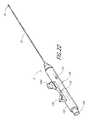
- FIG. 1illustrates one embodiment of a suturing apparatus and related assembly in an exemplifying use environment.
- FIG. 2illustrates an enlarged cross-sectional view of the suturing apparatus in an exemplifying use environment, such as a patient's thigh.
- FIG. 3is a perspective view of the suturing apparatus formed with an improved handle portion.
- FIG. 3Ais a perspective view of an arm trigger, which forms a portion of the handle portion of the suturing apparatus of FIG. 3 .
- FIG. 3Bis a perspective view of a needle trigger, which forms a portion of the handle portion of the suturing apparatus of FIG. 3 .
- FIG. 4is a side partial cross-sectional view of the handle portion wherein the arm trigger and needle trigger are in the non-depressed positions.
- FIG. 5is a side partial cross-sectional view of the handle portion wherein the arm trigger is fully depressed for locking the suture arms in the deployed condition.
- FIG. 6is a side partial cross-sectional view of the handle portion wherein both the arm trigger and the needle trigger are fully depressed for extending the needles to engage the suture ends held by the suture arms.
- FIG. 6Ais a side view illustrating the relationship between the needle trigger and the second follower member in the handle portion.
- FIG. 6Bis a perspective view of the second follower member.
- FIG. 7is a perspective view illustrating a preferred corner portion of the arm trigger wherein the corner portion is provided with a camming surface.
- FIG. 8is a side view illustrating a preferred embodiment of a release button for releasing the arm trigger and thereby retracting the suture arms.
- FIG. 9is a side view illustrating an alternative embodiment of a corner portion of the arm trigger wherein a section is cut away to facilitate the release of the arm trigger.
- FIG. 10is another perspective view illustrating a preferred corner portion of the arm trigger wherein the corner portion is provided with a camming surface.
- FIG. 11Ais an enlarged perspective view of the distal end portion of the suturing apparatus of FIG. 3 .
- FIG. 11Bis perspective view of the distal end portion of FIG. 11A with a pair of suture arms partially deployed.
- FIG. 11Cis a rear perspective view of the distal end portion of FIG. 11A with a pair of suture arms partially deployed.
- FIG. 12Ais a perspective view of a suture end having a flattened distal portion with an eyelet.
- FIG. 12Bis a perspective view of distal and proximal ends of a suture each having a flattened distal portion with an eyelet.
- FIG. 13is a cross-sectional view of the suturing apparatus of FIG. 3 with the distal end portion inserted through an arterial wall.
- FIG. 14is a cross-sectional view of the suturing apparatus of FIG. 3 with the distal end portion inserted through an arterial wall and a pair of suture arms partially deployed.
- FIG. 15is a cross-sectional view of the suturing apparatus of FIG. 3 with a pair of suture arms fully deployed and a pair of needles engaging the suture arms.
- FIG. 16is a perspective view illustrating an alternative embodiment of a needle trigger wherein the camming surface is provided by a pair of opposing pins with a gap therebetween.
- FIG. 17illustrates an exemplifying path of the camming surface of FIG. 16 during deployment and automatic retraction of the needles.
- FIG. 18is a side view illustrating an alternative configuration of the arm trigger and needle trigger wherein a compression spring is provided for biasing the triggers into the non-depressed positions.
- FIG. 19is a side view illustrating another alternative configuration of the arm trigger and needle trigger having a compression spring in a different location.
- FIG. 20is a perspective view illustrating an alternative embodiment of a follower member configured for engagement with the needle trigger of FIG. 16 , wherein the follower member is provided with an inclined surface and a return slot for guiding the opposing pins back to the starting position.
- FIG. 21is a perspective view illustrating one preferred embodiment of an extrusion clamp for securing the elongate body to the handle portion.
- FIG. 22is a perspective view illustrating an alternative embodiment of a suturing apparatus having an improved handle portion wherein the needle trigger includes a looped portion.
- FIG. 23is a perspective view illustrating another embodiment of a suturing apparatus.
- FIG. 24is a side view of the handle of the suturing apparatus of FIG. 23 , with a portion of a housing of the handle removed.
- FIG. 25is a perspective view of the first follower removed from the housing of FIG. 24 .
- FIG. 26is a perspective view of the first follower member of FIG. 25 from above.
- FIG. 27is a perspective view of the handle of the suturing apparatus of FIG. 23 , with the first follower removed.
- the assembly 4generally comprises a suturing apparatus 6 and a catheter sheath introducer (CSI) 8 .
- the suturing apparatus 6may be used to seal a blood vessel following an interventional catheterization procedure, such as an angiogram, angioplasty or other procedure.
- FIG. 2an enlarged view of the treatment site is illustrated. In this view it can be seen that a physician makes an initial incision 10 in an upper thigh region 12 of a patient 2 . The physician then inserts a needle (not shown) into the incision 10 such that the needle pierces a femoral artery 14 , creating a vessel incision 16 therein.
- the physicianWhen blood bleeds back from the insertion, the physician knows the needle has entered the femoral artery 14 . The physician then inserts a guidewire (not shown) through the needle and into the artery 14 . The physician may take the needle out and insert a plastic needle (not shown) over the guidewire once the guidewire is in place. The guidewire may then be taken out.
- the CSI 8is typically a single-lumen catheter with a valve located on its proximal end.
- the valveis configured to prevent extraneous bleed back and/or to introduce medication into the patient's body.
- the vessel incision 16provides access for medical instruments and probes inside the arterial vessel 14 .
- An instrument, such as a therapy catheter,may be advanced through the artery 14 via the CSI 8 to perform a procedure within the body.
- the physicianinserts the suturing apparatus 6 through the CSI 8 such that a suture introducer head 20 , distally attached to a hollow elongate body 32 , enters the first incision 10 , passes through the tissue 18 of the patient's thigh 12 , and enters the femoral artery 14 through the vessel incision 16 .
- the suture arms 24 , 24 ′are deployed and the introducer head 20 of the suturing apparatus is pulled back such that the suture arms contact the inner wall 22 of the femoral artery 14 .
- needlesare deployed from the introducer head which penetrate the wall 14 of the femoral artery 14 adjacent the incision 16 .
- the needlescapture suture ends from the suture arms and the needles are then retracted to withdraw the suture ends back through the wall of the femoral artery.
- the armsare then retracted and the entire suturing apparatus is withdrawn such that the suture ends may be tied together to close the incision.
- FIG. 3a preferred embodiment of the suturing apparatus 6 will be described in more detail. Additional details and methods of operation are described in Applicant's U.S. Pat. Nos. 6,245,079 and 6,562,052, each of which are hereby incorporated by reference in their entirety and are considered to be part of this specification. In addition, each of these patents is attached as an appendix. It will be appreciated that although the device 6 is preferably used for suturing vessel walls 22 , the device 6 can be used to suture other tissues such as, by way of example, a patent ductus arteriosus, a patent foramen ovale (PFO), a heart defect, a puncture wound, and the like.
- a patent ductus arteriosusa patent foramen ovale (PFO)
- PFOpatent foramen ovale
- the suturing apparatus 6generally comprises an elongate body 32 , an introducer head 20 and a handle portion 100 .
- the handle portion 100allows the physician to operate the suturing apparatus such that suture may be applied to an incision in a very quick and easy manner.
- the handle portionrequires very little manipulation during use and may be operated with a single hand if necessary.
- the suturing apparatusmay be used to close an incision located deep within the patient's tissue (e.g., in the femoral artery) without requiring the application of pressure over an extended period of time. As a result, the suturing apparatus may substantially reduce the recovery period following a medical procedure, thereby allowing the patient to return home more quickly and substantially reducing costs.
- the dimensions of the suturing apparatus 6may vary according to the suture site and the biological tissue intended to be sutured.
- the suture introducer head 20has a diameter of about 0.105 inches
- the hollow elongate body 32has a diameter of about 0.098 inches.
- the handle portion 100comprises a main housing 102 , an arm trigger 104 , a needle trigger 106 and an arm release button 108 .
- the arm and needle triggersprovide actuators for producing movement of internal components within the main housing, which in turn move at least one arm and needle for applying suture to a treatment site.
- the handle portionis constructed such that the arm trigger 104 , needle trigger 106 and arm release button 108 may be depressed by the physician in a particular order to extend and retract cooperating suture arms and needles along the introducer head 20 for applying suture to an incision.
- the arm and needle triggersare preferably pivotally coupled to the main housing 102 about pin 110 such that the triggers rotate as they are depressed by the physician. As will be described in more detail below, the pivotal rotation facilitates the cam-like interaction of the triggers with the internal components of the main housing.
- An opening 112is provided along the main housing 102 for allowing manual retraction of the needles in the event that the needles become stuck in the tissue during retraction. This provides a safety mechanism to ensure that the needles of the suturing apparatus cannot become stuck in the extended position.
- a tool(not shown) is inserted through the opening 112 in the main housing 102 for applying force to assist in the refraction of the needles.
- the arm trigger 104is shown in isolation. Loops 114 , 116 are provided along the distal end of the arm trigger for receiving the pin 110 in the main housing.
- the bottom corner portion 120 along the proximal end portion of the arm triggeris shaped with a protrusion 120 A which provides a camming surface for engaging a first slidable follower member in the main housing.
- the protrusionalso allows the arm trigger to be held in the depressed position for locking the arms in the deployed condition.
- the top surface 118 of the arm triggeris shaped for engagement with the physician's thumb or finger.
- the needle trigger 106is shown in isolation.
- Loop 122is provided along the proximal end of the needle trigger for receiving the pin 110 in the main housing.
- the loopis shaped to fit within the gap between the loops 114 , 116 of the arm trigger 104 (see FIG. 3A ).
- the bottom corner portion 130 along the distal end portion of the needle triggerprovides a camming surface for engagement with a second slidable follower member in the main housing.
- the top surface 128 of the needle triggeris shaped for engagement with the physician's thumb or finger.
- the internal componentscooperate with the arm and needle triggers 104 , 106 (i.e., actuators) and arm release button 108 for effecting movement of the arms and needles during the application of suture. More specifically, the arm and needle triggers actuate the arms and needles by effecting movement of the internal components contained with the main housing.
- the arm and needle triggerseach preferably have corner portions 120 , 130 shaped with camming surfaces which interact with first and second slidable follower members in the main housing. The follower members are caused to translate longitudinally when the arm or needle triggers are depressed by the physician.
- a cross-sectional side view of the handle portion 100is shown for purposes of illustration. It can be seen that a first follower member 140 is slidably disposed within the interior of the main housing 102 .
- the first follower member 140is connected to a proximal end of an actuating rod, preferably through a drive wire tab 156 described below, which extends distally through the main housing and elongate body for connection to each of the arms.
- each of the armsdeploys outward through apertures on the sides of the introducer head.
- the operation of the arms and needleswill be described in more detail below.
- longitudinal movement of the first follower member 140 relative to the main housingcontrols the position of the arms.
- An arm spring 144provides a biasing force to maintain the first follower member 140 in the distal position in the absence of any external input.
- arm springis shown for purposes of illustration, any known biasing mechanisms may be used for maintaining the first follower member 140 into the distal position.
- the first follower member 140is formed with an inclined “cammed” surface 142 along a distal face. As shown in FIG. 4 , the inclined cammed surface is configured for engagement with the camming surface along the corner portion 120 of the arm trigger 104 .
- the corner portion 120 of the arm trigger 104pushes along the inclined surface 142 of the first follower member 140 .
- the downward force acting on the inclined surfaceresults in longitudinal translation of the first follower member.
- the longitudinal forcecauses the first follower member to slide in a proximal direction (i.e., backward) within the main housing. As the first follower member slides backward, the actuating rod is pulled in a proximal direction, thereby causing the arms to deploy outward through the ports.
- the arm trigger 104is preferably releasably securable in the fully depressed condition for locking the arms in the deployed condition. As a result, it is not necessary for the physician to apply a constant a force on the arm trigger 104 to maintain the suture arms in the deployed condition.
- the corner portion 120 of the arm triggeris preferably formed with a protrusion 120 A.
- FIG. 7provides an enlarged view of the corner portion 120 including the protrusion 120 A.
- the protrusionis shaped to be captured and held beneath the first follower member 140 when the arm trigger 104 is fully depressed.
- the arm spring 144urges the first follower member forward (in the distal direction) such that the first follower member abuts the arm trigger and securely holds the protrusion. Accordingly, the cooperation of the protrusion and the first follower member creates a detent mechanism such that the arm trigger is selectively maintained in the depressed position.
- FIG. 10provides another perspective view of the corner portion of the arm trigger.
- the arm release button 108is configured for releasing the protrusion when it is desired to retract the deployable arms.
- the arm release button 108is preferably provided along a proximal end of the main housing 102 and is configured for engagement with the arm trigger 104 .
- An arm release spring 144may be provided for maintaining the arm release button 108 in the non-depressed condition in the absence of an external input. Accordingly, the arm release button can only act on the arm trigger when a sufficient force is applied to overcome the biasing force of the arm biasing spring 144 .
- the arm release button 108is shown in isolation.
- the arm release buttonis provided with an elongate member 108 A that is configured to contact the corner portion of the arm trigger when the arm trigger is being held in the fully depressed condition. More particularly, the elongate member 108 A is configured to urge the arm trigger in the distal direction such that the protrusion is released from the first follower member.
- FIG. 9is a cross-sectional view illustrating an alternative arm trigger wherein a section of the corner portion has been cut away to facilitate the release of the arm trigger upon actuation of the arm release button. It will be appreciated that alternative methods may be used to release the arm trigger.
- the arm triggermay be provided with a lip on its upper surface and an actuator may be used to engage the lip to pull the arm trigger back to its initial position.
- a second follower member 150is slidably disposed within the interior of the main housing at a location distal to the first follower member 140 .
- the second follower member 150is connected to the proximal ends of the elongate needles 70 , 70 ′.
- longitudinal movement of the second follower member 150 relative to the main housing 102effects the position of the needles.
- the second follower member 150has a proximal position (as shown in FIGS. 4 and 5 ) wherein the needles are in the retracted (non-deployed condition).
- a needle biasing spring 154engages the second follower member for maintaining the second follower member in the proximal position in the absence of any external input. Although one particular embodiment of a needle biasing spring 154 is shown for purposes of illustration, a wide variety of different biasing mechanisms may be used for biasing the second follower member into the proximal position.
- the second follower member 150is provided with an inclined “cammed” surface 152 along the proximal face such that the second follower member cooperates with a camming surface along the corner portion 130 of the needle trigger 106 in a manner substantially similar to that of the first follower member. More particularly, as shown in FIG. 5 , the inclined surface is shaped for slidable engagement with a camming surface of the needle trigger 106 .
- the camming surface along the corner portion 130 of the needle triggerpushes against the inclined surface 152 of the second follower member 150 , as illustrated in the cross-sectional view of FIG. 6A .
- the force from the needle triggercreates a resulting longitudinal force on the second follower member that causes the second follower member to slide distally relative to the main housing.
- the needles 70 , 70 ′are pushed in a distal direction, thereby causing the distal end portions of the needles to extend outward from the introducer head for engagement with the suture arms.
- the second follower member 150is contained within a body portion that is integral with the first follower member.
- the body portionprovides a slotted track such that the second follower member may be guided proximally and distally during use.
- the first and second follower membersare preferably slidably coupled to each other.
- the second follower membermay be formed with a longitudinal lumen for slidably receiving the actuating rod 58 . Accordingly, the actuating rod 58 may be slid longitudinally by movement of the first follower member without interfering with the second follower member.
- FIG. 6Bprovides a perspective view of the second follower member 150 having an inclined surface 152 . It can be seen that the lower portion of the second follower member is thinner in construction. The thinner section is configured to fit within a groove in the body portion for guiding the movement of the second follower member, as described above.
- the second follower memberis also formed with a slot 160 for receiving a tool through the window 112 in the main housing 102 ( FIG. 3 ). The tool may be inserted through the window and into the slot. The tool may then be used to slide the second follower member in the event that it sticks, thereby providing a safety mechanism as described above.
- the cammed surface of the first and second follower membersis shaped to produce a desired motion in response to actuation of the arm and needle triggers, respectively.
- at least a portion the cammed surface of the second follower memberis inclined at about 35° or more relative to the longitudinal axis.
- the angle of inclinationis denoted by the symbol ⁇ (alpha) in FIG. 6A .
- at least a portion of the cammed surfaceis inclined at about 40° or more relative to the axis.
- at least a portion of the cammed surfaceis inclined at about 41° relative to the axis.
- at least a portion of the cammed surfaceis inclined at between about 35-45° relative to the axis.
- At least a portion of the cammed surfaceis inclined at between about 39-43° relative to the axis. In another variation, at least a portion of the cammed surface is inclined at between about 40-42° relative to the axis. In still another variation, the camming surface is curved. The same preferred ranges also apply to the cammed surface of the first follower member. It will be appreciated that the ratio of trigger movement to needle movement is proportional to the angle of the inclined surface. It has been found that the above angles provide excellent performance while minimizing the diameter of the handle portion. For example, a lower angle would make the follower members more difficult to move due to frictional forces.
- an inclined surface formed with a substantially constant angleprovides a substantially directly proportional relationship between trigger movement and needle movement. As a result, the physician is able to advance and retract the needles with great precision and predictability by controlling the movement of the needle trigger.
- the main housing 102is preferably constructed of a translucent or transparent material, such as plastic, such that the movement of the components within the main housing is visible to the physician.
- the transparencyadvantageously provides visual feedback to the physician regarding operation of the suturing apparatus.
- markings or other indiciamay be provided such that the position of the needles may be easily perceived during use.
- a windowmay be provided for observing the movement of the internal components or a portion of one or more internal components may extend through the main housing to an exterior surface for purposes of visibility.
- the distal end portionprovides one preferred embodiment that may be operated using the improved handle portion described above.
- the distal end portioncomprises the suture introducer head 20 , a pair of suture arms 24 , 24 ′, a pair of suture clasps 56 , 56 ′, a pair of suture arm apertures 50 , 50 ′, a pair of curved or slanted needle guides 48 , 48 ′, a pair of needle apertures 30 , 30 ′, a distal end 54 , a hole 46 , a suture 52 and an actuating rod 58 .
- the distal end portionfurther comprises a pair of needles 70 , 70 ′ (see FIGS. 13 through 15 ).
- the suture arms 24 , 24 ′are retracted into the suture arm apertures 50 , 50 ′ and the needles 70 , 70 ′ are refracted into the needle apertures 30 , 30 ′, the arms 24 , 24 ′ and the needles 70 , 70 ′ are recessed within the suture introducer head 20 , as shown in FIG. 11A . This prevents the arms 24 , 24 ′ and the needles 70 , 70 ′ from causing tissue damage while the distal end portion passes through a biological structure.
- FIGS. 11B and 11Cillustrate the distal end portion of the device 6 ( FIG. 3 ) with the suture arms 24 , 24 ′ partially deployed outwardly from their recessed positions.
- Such deploymentis achieved by partially depressing the arm trigger 104 , as described above with reference to FIGS. 4 through 6 .
- Depressing the arm trigger 104translates the first follower member 140 ( FIG. 4 ) and actuating rod 58 proximally, which brings the suture arms 24 , 24 ′ into contact with a pair of proximal inside edges 78 , 78 ′ of the suture arm apertures 50 , 50 ′.
- the proximal inside edges 78 , 78 ′force the suture arms 24 , 24 ′ into a deployed state.
- the suture arms 24 , 24 ′continue to deploy radially until the arms 24 , 24 ′ are substantially parallel with each other and substantially perpendicular to the longitudinal axis of the suture introducer head 20 , as shown in FIG. 15 .
- the suture arms 24 , 24 ′may be “fully” deployed when they reach an acute or obtuse angle relative to each other.
- each of the suture arms 24 , 24 ′comprises a suture clasp 56 , 56 ′ which holds an end of the suture 52 .
- Each of the suture arms 24 , 24 ′are pre-loaded with the ends of the suture 52 before operation.
- the ends of the suture 52then pass from the suture clasps 56 , 56 ′ to the hole 46 whereby the ends of the suture 52 enter the suture introducer head 20 and are passed proximally through the hollow elongate body 32 .
- each end of the suture 52has a capture portion comprising a loop which is tied onto the ends of the suture claps 56 , 56 ′. It is contemplated, however, that the capture portions are not restricted solely to tied loops, rather other types of capture portions may be utilized such as, by way of example, spheres or ferrules.
- FIG. 12Aillustrates another embodiment of a capture portion wherein the end of the suture 52 comprises a flattened distal region 93 having a hole or eyelet 95 .
- the suture 52comprises a strand 91 of deformable material that is preferably monofilament, such as Deklene (from Genzyme), Prolene (from Johnson & Johnson), or Nylon (from Johnson & Johnson).
- the strand 91is advantageously approximately 0.010′′ thick and has a length that makes it suitable for use in suture procedures.
- the distal end of the strand 91is heated until the distal end melts or is otherwise plastically or thermally deformed to form a locally deformed region (such as a globule) that is broader than the rest of the strand 91 in at least one dimension (i.e., at least one dimension of the strand 91 has been increased).
- a locally deformed regionsuch as a globule
- the strand 91may be allowed to cool, and the deformed region may then be flattened by use of a die.
- the diepreferably has a relief or recessed portion for accepting the strand 91 and the deformed region.
- a blockwhich preferably also has a recessed portion that mates with the recessed portion, may then be placed over the deformed region.
- the deformed regionis then squeezed between the die and the block, resulting in the formation of the flattened distal portion 93 illustrated in FIG. 12A .
- the flattened distal portion 93preferably has a thickness that matches the rest of the strand 91 .
- the edges of the flattened distal portion 93may then be trimmed to form a smooth disc portion to reduce the risk of such edges snagging on vessel walls during suturing procedures.
- the eyelet 95is formed within the flattened distal portion 93 .
- a punchsuch as a hypotube may be used to poke through the flattened distal portion 93 , thereby leaving the eyelet 95 within the flattened distal portion 93 .
- the eyelet 95is formed such that a surgical hook or needle may pass through the eyelet 95 in a suturing procedure.
- the flattened distal portion 93acts as a connector to the hook or needle, allowing the strand 91 to be picked up by the hook or needle.
- the method of forming the eyelet 95 described herein, including the forming of the flattened distal portion 93 ,advantageously results in no significant reduction in the mechanical strength of the strand 91 , with the material throughout the strand 91 (including the material in the flattened distal portion 93 ) having substantially uniform mechanical strength.
- Methods for forming the flattened distal region 93are discussed in greater detail in Applicant's above-mentioned U.S. Pat. No. 6,562,052, entitled SUTURING DEVICE AND METHOD.
- the suture embodiment shown in FIG. 12Ahas no knots or ties formed therein which might increase the profile of the suture strand 91 or make it easier for the suture 52 to snag during use.
- This processmay advantageously be repeated at the proximal end of the strand 91 , resulting in eyelets 95 , 95 ′ at both ends of the strand 91 , as illustrated in FIG. 12B .
- the flattened distal portion 93 at one or more of the ends of the strand 91may be bent (not shown) at an angle with respect to the rest of the strand 91 to facilitate the guiding of a surgical needle through the eyelet 95 .
- FIG. 11Cillustrates one preferred configuration of the hollow elongate body 32 which comprises five lumens. Two of the lumens 60 , 60 ′ are used to house the needles 70 , 70 ′. Once the suture arms 24 , 24 ′ have been deployed, as discussed with reference to FIGS. 11B and 11C (and in greater detail below), the needle trigger 106 ( FIG. 3 ) can be depressed to advance the needles 70 , 70 ′ from a recessed position within the suture introducer head 20 to a distally extended position (see FIG. 15 ). In one embodiment, the needles 70 , 70 ′ move distally at substantially the same time. In another embodiment, the needles 70 , 70 ′ may be actuated separately such that one of the needles 70 , 70 ′ advances before the other.
- the needles 70 , 70 ′are flexible and preferably made of a material with shape memory, such as SUPERFLEX NITINOLTM.
- the needles 70 , 70 ′may be comprised of spring steel, surgical stainless steel or any variation thereof.
- Each of the needles 70 , 70 ′preferably has a diameter of about 0.019 inches, but needles with other diameters may be used in accordance with the particular medical procedure contemplated.
- FIG. 15a further outward, radial bend preferably is imparted to the needles 70 , 70 ′ when they come into contact with a pair of angled surfaces 57 , 57 ′ of the suture arms 24 , 24 ′.
- the needles 70 , 70 ′are refracted into the needle lumens 60 , 60 ′, the needles 70 , 70 ′ resume a straight configuration as a result of their resiliency.
- FIGS. 11A through 15preferably comprises flexible needles 70 , 70 ′, which bend during deployment, it is contemplated that other embodiments may advantageously comprise rigid needles which may be permanently straight or curved.
- the hollow elongate body 32contains a central lumen 64 which is used to house the actuating rod 58 .
- Another lumen 62is used to house the length of the suture 52 to prevent the suture 52 from becoming tangled.
- the suture 52may be passed through the central lumen 64 along with the actuating rod 58 .
- a fifth lumen 62 ′is preferably used for “bleed back,” which enables the physician to determine whether the distal end 54 of the suture introducer head 20 is positioned within the artery 14 .
- Bleed backis accomplished through the hole 46 at the distal end 54 of the suture introducer head 20 , the suture arm apertures 50 , 50 ′ and any other openings in the suture introducer head 20 .
- the direction of blood flow for bleed backis indicated by three dashed arrows in FIG. 13 . If the distal end 54 of the suture introducer head 20 is positioned within the artery 14 , blood pressure due to blood entering into the hole 46 will be much greater than if the distal end 54 is not within the artery 14 .
- the lumen 62 ′extends to a port (not shown) at a proximal portion of the device 6 , whereby the physician can determine the blood pressure within the bleed back lumen 62 ′ by monitoring blood flow from the port.
- the lumen 62 ′may be attached to a balloon which inflates when the distal end 54 of the suture introducer head 20 passes into the blood vessel 14 .
- a pressure sensormay be coupled with the lumen 62 ′ to provide the physician with a numeric blood pressure reading.
- the lumen 62 ′may be used to inject medication or for diagnostic purposes.
- two thin stripes 66(only one shown in FIG. 11C ) marked on the exterior of the hollow elongate body 32 extend along the entire length of the hollow elongate body 32 .
- the stripes 66provide a visual indication of the circumferential location of the needles 70 , 70 ′ relative to the hollow elongate body 32 .
- the stripes 66facilitate aligning the needles 70 , 70 ′ with the axis of the blood vessel 14 , so that needle incisions 80 , 80 ′ (see FIG. 15 ) formed in the vessel wall 22 by the needles 70 , 70 ′ will be aligned along a dimension transverse to the flow of blood within the artery 14 .
- the hollow elongate body 32may have only one stripe 66 which denotes the circumferential location of one of the two needles 70 , 70 ′. Because the needles 70 , 70 ′ deploy from opposite sides of the suture introducer head 20 , knowledge of the location of one needle provides the physician with knowledge of the location of the other needle.
- the exterior surface of the hollow elongate body 32includes a marker 68 which denotes a proximal position to which the CSI 8 should be partially withdrawn (after the distal portion 26 of the suturing apparatus 6 has been inserted into the blood vessel 14 ) to expose the needle apertures 30 , 30 ′.
- the partial withdrawal of the CSI 8is discussed in detail in Applicant's above-mentioned U.S. Pat. No. 6,562,052, entitled SUTURING DEVICE AND METHOD.
- the marker 68is shown as a visual marker, but may additionally or alternatively be in the form of a ridge, groove, or other physical structure which interacts with a corresponding structure of the CSI 8 to allow the physician to position the CSI 8 using a sense of feel.
- the CSI 8 and the hollow elongate body 32could be configured to releasably engage or interlock with one another when the CSI 8 reaches a predetermined position along the elongate body 32 . It is contemplated that a specially formed CSI 8 comprises such an interlocking structure, and is included within the scope of the invention.
- one or more additional markersmay advantageously be provided along the length of the hollow elongate body 32 , distal to the marker 68 , to indicate other positions of the CSI 8 relative to the elongate body 32 , such as the position at which the suture arms 24 , 24 ′ are exposed outside the CSI 8 .
- the handle portion 100provides an improved mechanism for quickly and easily actuating the components of the suturing apparatus to apply suture to an incision, such as to close a vessel wall after a surgical procedure.
- each end of a suturehas a capture portion comprised of a loop, a sphere or a ferrule.
- the loop, sphere or ferrulemay be formed (e.g., by heat molding) with the same suture material as the length of suture.
- the loop, sphere or ferrulemay be a separate piece attached (e.g., molded, glued, etc.) onto each end of the length of suture. The loop, sphere or ferrule is loaded in respective suture end supports of the arms 24 , 24 ′.
- the remaining length of the suturepreferably extends through the hollow elongate body.
- the physicianWith the CSI 8 extending into the patient's artery 14 , the physician then inserts the suture introducer head 20 through the CSI 8 and into the artery 14 .
- the CSI 8is then partially withdrawn along the hollow elongate body 32 to remove the CSI 8 from the artery 14 and to expose the needle apertures 30 , 30 ′, as shown in FIG. 13 .
- the markers 68 ( FIG. 11C ) on the exterior surface of the hollow elongate body 32indicate how far the physician should withdraw the CSI 8 to expose the needle apertures 30 , 30 ′.
- the distal end 54 of the suture introducer head 20has a smooth, rounded surface which prevents injury to the opposite vessel wall 22 when the suture introducer head 20 is inserted into the artery 14 .
- blood flow within the artery 14is uninterrupted because the suture introducer head 20 does not occlude the artery 14 .
- the physicianmay use bleed back through the hole 46 and the lumen 62 ′ ( FIG. 11C ) to determine when the suture introducer head 20 has entered into the artery 14 .
- the arm trigger 104 and needle trigger 106are each in the non-depressed positions, as depicted in FIG. 4 .
- the first followeris located in the distal position such that the suture arms are in the retracted condition.
- the second followeris in the proximal position such that the needles are in the retracted condition.
- the actuating rod 58holds the suture arms 24 , 24 ′ in a recessed state within the suture introducer head 20 .
- the actuating rod 58applies a downward force while a pair of deflection surfaces 67 , 67 ′ of the suture introducer head 20 apply an inward force on each of the suture arms 24 , 24 ′, respectively.
- the combination of these two forcesretains the suture arms 24 , 24 ′ within the suture arm apertures 50 , 50 ′ of the suture introducer head 20 .
- Each of the suture clasps 56 , 56 ′comprises an angled slot which holds a looped end of the suture 52 as illustrated in FIGS. 11A through 11C .
- the looped ends of the suture 52are held securely by the suture clasps 56 , 56 ′, but are positioned for easy removal by a pair of suture catches 72 , 72 ′ at the tips of the needles 70 , 70 ′.
- the physiciandepresses the arm trigger 104 ( FIG. 3 ) to deploy the suture arms 24 , 24 ′ as shown in FIG. 14 .
- Downward movement of the arm triggeracts on the first follower member 140 in the main housing 102 , thereby causing the first follower member to translate proximally, which pulls the actuating rod proximally.
- the corner portion 120 of the arm trigger 104provides a camming surface which engages an inclined cammed surface on the first follower member 140 . During this action, the force applied on the arm trigger must be sufficient to overcome the biasing force of the arm spring 144 .
- Movement of the first follower member 140translates the actuating rod 58 proximally, which relieves the downward force applied by the actuating rod 58 and thus also relieves the inward forces applied to the suture arms 24 , 24 ′ by the deflection surfaces 67 , 67 ′.
- Thisallows the suture arms 24 , 24 ′ to assume a partially deployed state as illustrated in FIG. 14 .
- the actuating rod 58continues translating proximally, bringing the suture arms 24 , 24 ′ into contact with the proximal inside edges 78 , 78 ′.
- the proximal inside edges 78 , 78 ′apply a downward force on each of the suture arms 24 , 24 ′, respectively, thereby forcing the suture arms 24 , 24 ′ into a fully deployed state as illustrated in FIG. 15 .
- the arm trigger 104becomes fully depressed, the protrusion 120 A along the corner portion 120 of the arm trigger 104 advances beneath the first follower body 140 .
- the arm trigger 104is maintained in the fully depressed position by the force of the arm spring 144 , which pushes the first follower body against the arm trigger.
- the cooperation between the arm trigger and the first follower bodyadvantageously provides a releasable detent mechanism for holding the arm trigger in the depressed position.
- the suture arms 24 , 24 ′are locked in the fully deployed condition.
- the suture arms 24 , 24 ′preferably have reached a fully extended position and are longitudinally aligned with each other, as illustrated in FIG. 15 .
- the physicianmay gently slide the suturing apparatus 6 proximally so that the suture arms 24 , 24 ′ contact the interior surface of the vessel wall 22 .
- FIG. 5illustrates the needle trigger in the non-depressed position.
- FIG. 6illustrates the needle trigger in the fully depressed position.
- the camming surface along the corner portion 130 of the needle trigger 106engages and slides along the cammed surface of the second follower member 150 , thereby causing the second follower member to slide longitudinally within the main housing 102 in a distal direction.
- the force applied on the needle trigger 106must be sufficient to overcome the biasing force of the needle biasing spring 154 .
- the second follower membercontinues to slide distally, thereby advancing the needles distally through the main housing and through the hollow elongate body. As the first and second needles advance distally, the distal ends of the needles extend outward for engagement with the arms.
- the paths taken by the needles 70 , 70 ′are illustrated in FIG. 15 .
- the needles 70 , 70 ′slide along the needle lumens 60 , 60 ′ and out of the suture device 6 through the needle apertures 30 , 30 ′, respectively.
- the needles 70 , 70 ′come in contact with the needle insertion guides 48 , 48 ′, the needles 70 , 70 ′ begin to bend radially outward.
- the angle of the needle deflectionis preferably about 13.2 degrees. Deflection angles between about 10 degrees and about 15 degrees and between about 5 degrees and about 20 degrees are also contemplated.
- the needles 70 , 70 ′penetrate the vessel wall 22 at an angle, thereby creating the needle incisions 80 , 80 ′ on opposite sides of the incision 16 .
- the needles 70 , 70 ′also preferably bend slightly (radially outward) when they come in contact with the suture arms 24 , 24 ′.
- the angled surfaces 57 , 57 ′ of the suture clasps 56 , 56 ′ and the suture catches 72 , 72 ′exert a force on each of the looped ends of the suture 52 such that the looped ends remain tied to the suture clasps 56 , 56 ′ while the needles 70 , 70 ′ pass therein.
- the physiciandepresses the needle trigger 106 until the suture catches 72 , 72 ′ of the needles 70 , 70 ′ engage the suture clasps 56 , 56 ′ and capture the looped ends of the suture 52 .
- the suture arms 24 , 24 ′hold the looped ends of the suture 52 away from the suture introducer head 20 so that the needles 70 , 70 ′ pierce the vessel wall 22 and capture the looped ends of the suture 52 outside the perimeter of the suture introducer head 20 .
- Mechanical limitsprevent additional movement of the needle trigger 106 once the needles 70 , 70 ′ have optimally engaged the suture clasps 56 , 56 ′.
- Such resistancesignals to the physician that the needles 70 , 70 ′ have reached an optimal, predetermined location within the suture clasps 56 , 56 ′.
- the physicianadvances the needles 70 , 70 ′ to the optimal, predetermined location within the suture clasps 56 , 56 ′
- the physicianreleases pressure on the needle trigger 106 , thereby allowing the needle biasing spring 154 within the handle portion 100 (see FIGS. 4-6 ) to retract the needles 70 , 70 ′ proximally.
- This motioncauses the needles 70 , 70 ′ to withdraw into the needle lumens 60 , 60 ′ with the looped ends of the suture 52 attached to the suture catches 72 , 72 ′.
- the suture catches 72 , 72 ′capture the looped ends of the suture 52 held by the suture clasps 56 , 56 ′ and pull the looped ends up through the needle incisions 80 , 80 ′ as the needles 70 , 70 ′ retract proximally.
- tension in the suture 52causes additional segments of the suture 52 to feed through the hole 46 at the distal end 54 of the suture introducer head 20 , into the artery 14 and through the needle incisions 80 , 80 ′.
- the physicianmay regulate the rate of needle movement by controlling the rate of movement of the needle trigger. From the above, it can be seen that the position of the needles is substantially directly proportional with the position of the needle trigger. Accordingly, by sensing the position of the needle trigger, the physician is provided with a reliable indication of needle position at any given time.
- the physicianadvantageously controls the position of the needles 70 , 70 ′ by depressing and releasing the needle trigger 104 .
- the advancement of the needleis achieved by depressing the needle trigger in a controlled manner, while retraction is achieved by allowing the needle spring to retract the needle while the physician regulates the rate of retraction with the needle trigger.
- the physiciandepresses the arm release button 108 ( FIG. 3 ) to release the arm trigger 104 .
- the arm release buttonurges the corner portion 120 of the arm trigger 104 in a distal direction such that the protrusion 120 A is released from the first follower member 140 , thereby allowing the arm trigger 104 to spring back upward.
- the arm biasing spring 144pushes the first follower member 140 distally, thereby moving the actuating rod 58 distally. This relieves the forces applied to the suture arms 24 , 24 ′ by the proximal inside edges 78 , 78 ′, allowing the suture arms 24 , 24 ′ to assume a relaxed state as illustrated in FIG. 14 . Upon further distal movement of the first follower member 140 , the suture arms 24 , 24 ′ move distally until contacting the deflection surfaces 67 , 67 ′.
- the downward force of the actuating rod 58causes the suture arms 24 , 24 ′ to retract into the recessed state within the suture introducer head 20 , as shown in FIG. 13 .
- the suture arms 24 , 24 ′are substantially parallel with the hollow elongate body 32 , and the exterior surfaces of the suture arms 24 , 24 ′ are substantially flush with the exterior surface of the introducer head 20 . This reduces the likelihood that the suture arms 24 , 24 ′ will snag or catch on the vessel wall 22 or the flesh 18 during withdrawal.
- the suture arms 24 , 24 ′ and the needles 70 , 70 ′returned to the recessed state, the device 6 is ready for removal from the artery 14 .
- the physicianthen withdraws the device 6 out of the artery 14 and out of the tissue 18 of the patient's thigh 12 .
- the physiciangently pulls the ends of the suture 52 to close the vessel incision 16 .
- the suture 52passes through the needle incisions 80 , 80 ′, when the ends of the suture 52 are pulled, tension in the suture 52 closes the vessel incision 16 .
- the physicianthen ties at least one knot, preferably a fisherman's knot or an improved clinch knot, with the ends of the suture 52 and slides or pushes the knot(s) down through the CSI 8 to the vessel incision 16 .
- the physicianmay tie and push the knot(s) by using any suitable suture knot tying and/or cinching apparatus including an apparatus disclosed in Applicant's application entitled METHOD AND APPARATUS FOR TYING SUTURE KNOTS, Ser. No. 09/923,108, filed Aug. 6, 2001, the entirety of which is hereby incorporated by reference.
- the physicianmay tie at least one knot by hand and then cinch the knot by using a knot cinching device, such as an apparatus taught by Applicant's application titled KNOT PUSHER, Ser. No. 09/571,759, filed May 15, 2000, which is incorporated herein by reference in its entirety. Still, the physician may choose to fasten a small, circular or flat stainless steel clip (not shown) to the ends of the suture 52 and slide the clip down through the CSI 8 to the vessel incision 16 to close the incision 16 . Other embodiments for tying and placing knots are described in Applicant's application entitled HANDLE FOR SUTURING APPARATUS, Ser. No. 60/613,636, filed Sep.
- the suturing apparatusmay be provided with a lumen for slidably receiving a guidewire.
- the guidewire lumenmay be combined with the bleed back lumen. The guidewire lumen is provided for assisting the physician during insertion of the suturing apparatus into the patient and advancing the device toward the treatment site.
- a needle trigger 206is formed with first and second pins 208 , 210 and a gap therebetween.
- the needle triggeris configured for cooperation with the follower member 250 shown in FIG. 20 .
- the pins 208 , 210 of the needle trigger 206initially ride along the inclined surface 252 of the follower member 250 , thereby causing the follower member to move in a distal direction for extending the needles.
- FIG. 17illustrates an exemplifying path of the pins during this cycle.
- FIGS. 18 and 19illustrate spring mechanism 258 or 260 for biasing the arm and needle triggers back into the start position.
- the relationship between the needle trigger and the follower membermay be configured such that the needles retract from the first finished position at a first rate and then retract from a second finished position at a faster rate. This may be achieved by providing a cut away portion (such as in FIG. 9 ) on the follower member.
- This retraction of the needles at a slow rate followed by a fast rateadvantageously provides a “pre-tensioning” of the suture such that the needles initially tug slowly on the suture ends and then more quickly. The initial slow tugging allows the suture ends to become better aligned before withdrawal through the tissue.
- the clampprovides a transition between the handle portion 100 and the elongate body.
- the clampincludes a central lumen 182 for receiving the actuator rod and needles.
- the clampalso includes a depression for seating the needle biasing spring 154 .
- the needle trigger 106 Amay be provided with a looped portion configured to receive the physician's thumb or finger.
- the looped portionadvantageously allows the physician to pull upward on the needle trigger without relying on the biasing spring force to raise the needle trigger. This embodiment provides the physician with greater control over the movement of the needles.
- the suturing apparatusmay be provided without an arm release button.
- the arm triggercould be constructed such that the initial depression moves the arm trigger into the locked position. Pressing the arm trigger again causes the arm trigger to become released and pop back up. Any release mechanism of the types known in the art may be used for this purpose.
- first and second thumb wheelsmay be provided along the handle portion for moving the first and second follower members.
- the interaction between the thumb wheels and the follower memberspreferably employs a rack and pinion system of the type known in the art. This embodiment provides the physician with even greater control over the position of the suture arms and needles.
- FIGS. 23-27illustrate an alternative embodiment of a suturing apparatus 300 , wherein the release button 108 is provided along the side, rather than extending axially from the proximal end, of the main housing 102 .
- the suturing apparatus 300generally comprises an elongate body 32 and an introducer head 20 as described above, and a handle portion 100 ′ as described further below.
- the handle portion 100 ′comprises a main housing 102 , an arm trigger 104 and a needle trigger 106 as described above, and an arm release button 108 ′.
- the arm trigger, needle trigger and arm release button 108 ′preferably include markings to indicate the order in which the triggers are actuated, e.g., the arm trigger 104 is labeled “1,” the needle trigger 106 is labeled “2,” and the arm release button 108 ′ is labeled “3.”
- the arm and needle triggersare preferably pivotally coupled to the main housing 102 about pin 110 such that the triggers rotate as they are depressed by the physician.
- the arm needle trigger 104When the arm needle trigger 104 is depressed, it engages a first follower member 140 ′ that is slidably received in the main housing 102 .
- the first follower member 140 ′shown more particularly in FIGS. 25 and 26 , comprises an elongate body 302 having a proximal end 304 and a distal end 306 with a slot 308 extending longitudinally through the elongate body along a top side thereof.
- the elongate body 302has a partially circular cross-section, with a proximal portion 310 of the slot receiving the arm trigger 104 when depressed.
- an intermediate portion 312 of the slotis provided that partially receives the needle trigger 106 when depressed.
- a distal portion 314 of the slotis provided that partially receives the needle trigger 106 when depressed, and also receives the second follower member 150 , as described further below.
- longitudinal grooves 316are provided to receive an arm lockout wire 330 , described further below.
- An inclined ramp 142 ′such as described above is provided within the portion 310 of the slot to engage the arm trigger 104 .
- a drive wire tab 156 as illustrated also in the embodiments aboveis preferably secured to the distal end of the first follower member 140 ′, such as by pins through holes 158 .
- the tab 156is secured to the actuating rod 58 , which extends through the central lumen 182 of extrusion clamp 180 .
- FIG. 27illustrates the handle 100 ′ with the first follower member 140 ′ removed.
- a downwardly extending leg 336extends from a lower surface of the needle trigger 106 .
- a ledge 338 on the first follower membershown in FIG. 26 , is positioned below the leg 336 , preventing the needle trigger 106 from being depressed.
- the ledge 338also moves proximally to allow downward movement of the needle trigger 106 . This prevents the needle trigger 106 from being actuated until after the arms are deployed by depressing arm trigger 104 .
- the needle trigger 106when depressed, engages a cammed surface 152 of second follower member 150 , causing the second follower member 150 to compress needle biasing spring 154 , as described above.
- the second follower member 150is provided in the distal portion 314 of the slot 308 and is capable of sliding relative to the first follower member.
- Proximal of the first follower member 140 ′is an arm spring 144
- proximal of arm spring 144is third follower member 320 , which has an inclined surface 322 which engages arm release button 108 ′.
- Third follower memberhas longitudinal grooves 324 on both sides thereof to receive the arm lockout wire 330 described below.
- Elongate member 108 A′extends distally from the third follower member 320 underneath the arm spring 144 .
- an arm lockout wire 330extends proximally from the one side of the second follower member 150 , through the longitudinal groove 316 on one side of the elongate body 302 of the first follower member 140 ′, through the longitudinal groove 324 on one side of the third follower member 320 , around the proximal end of the third follower member, and back through the grooves 324 and 316 on the opposite side of the housing and connecting with the second follower member 150 .
- arm lockout wire 330also moves distally, and becomes positioned underneath the arm release button 108 ′. This prevents the arm release button 108 ′ from being depressed while the needles are being actuated, until the second follower member returns to its initial position.
- the main housing of the handle portion 100 ′includes a safety opening or window 112 as described above for manually retracting the needles.
- the main housingalso includes a safety opening or window 113 for manually retracting the arms.
- the opening 112cooperates with the opening 332 in second follower member 150 , allowing for a pin to be inserted into the openings to manually bring the second follower member back to its initial configuration.
- the opening 113cooperates with the opening 334 in the first follower member 140 ′ for the same purpose.
- Operation of the suturing assembly 300 as illustrated in FIGS. 23-27first begins, after appropriate placement of the assembly, by depressing arm trigger 104 labeled “1”.
- Depressing arm trigger 104causes the first follower member 140 ′ to move proximally within the housing 102 , compressing arm spring 144 and moving actuating rod 58 to deploy the arms 24 , 24 ′ described above.
- Arm trigger 104preferably can be depressed until it is secured or locked in a down position, such as described with the embodiment of FIG. 7 above.
- depressing needle trigger 106 labeled “2”causes the second follower member 150 to slide distally within the slot of first follower member 140 ′, compressing the needle biasing spring 154 and causing needles 70 and 70 ′ to splay outward from the elongated body 32 .
- the needle trigger 106may be configured such as described with respect to FIG. 16 above. More particularly, the needle trigger 106 may have pins 208 , 210 that ride initially along an inclined surface of the second follower member 150 , thereby causing the follower member to move in a distal direction for extending the needles.
- the pinsextend beyond the bottom edge of the inclined surface, thereby relieving the force on the follower member and allowing the follower member to snap back in a proximal direction. This occurs while maintaining the needle trigger in the fully depressed condition. Accordingly, the needles are first fully extended and then automatically snap back when the needle trigger reaches a first finished position (i.e., is fully depressed).
- the needle triggermay remain in its depressed configuration after the second follower member 150 snaps back to its original configuration, or the needle trigger may automatically return to its initial configuration. If the needle trigger 106 does not automatically return to its initial configuration, the operator may simply pull the needle trigger upward along the body of the second follower member, spreading the gap between the pins 208 , 210 until the pins are once again above the inclined surface.
- the operatorpresses down on the arm release button 108 ′, labeled “3”. This causes the third follower member 320 to move distally, and causes the elongate member 108 A′ to contact a corner portion of the arm trigger 104 and urge the arm trigger distally so that it is released from the first follower member 140 ′.
Landscapes
- Health & Medical Sciences (AREA)
- Surgery (AREA)
- Life Sciences & Earth Sciences (AREA)
- Biomedical Technology (AREA)
- Nuclear Medicine, Radiotherapy & Molecular Imaging (AREA)
- Engineering & Computer Science (AREA)
- Heart & Thoracic Surgery (AREA)
- Medical Informatics (AREA)
- Molecular Biology (AREA)
- Animal Behavior & Ethology (AREA)
- General Health & Medical Sciences (AREA)
- Public Health (AREA)
- Veterinary Medicine (AREA)
- Cardiology (AREA)
- Surgical Instruments (AREA)
Abstract
Description
Claims (23)
Priority Applications (1)
| Application Number | Priority Date | Filing Date | Title |
|---|---|---|---|
| US12/890,196US8496676B2 (en) | 2004-09-27 | 2010-09-24 | Handle for suturing apparatus |
Applications Claiming Priority (3)
| Application Number | Priority Date | Filing Date | Title |
|---|---|---|---|
| US61363604P | 2004-09-27 | 2004-09-27 | |
| US11/235,751US7803167B2 (en) | 2004-09-27 | 2005-09-27 | Handle for suturing apparatus |
| US12/890,196US8496676B2 (en) | 2004-09-27 | 2010-09-24 | Handle for suturing apparatus |
Related Parent Applications (1)
| Application Number | Title | Priority Date | Filing Date |
|---|---|---|---|
| US11/235,751DivisionUS7803167B2 (en) | 2004-09-27 | 2005-09-27 | Handle for suturing apparatus |
Publications (2)
| Publication Number | Publication Date |
|---|---|
| US20110015655A1 US20110015655A1 (en) | 2011-01-20 |
| US8496676B2true US8496676B2 (en) | 2013-07-30 |
Family
ID=35614656
Family Applications (2)
| Application Number | Title | Priority Date | Filing Date |
|---|---|---|---|
| US11/235,751Active2029-04-08US7803167B2 (en) | 2004-09-27 | 2005-09-27 | Handle for suturing apparatus |
| US12/890,196Expired - Fee RelatedUS8496676B2 (en) | 2004-09-27 | 2010-09-24 | Handle for suturing apparatus |
Family Applications Before (1)
| Application Number | Title | Priority Date | Filing Date |
|---|---|---|---|
| US11/235,751Active2029-04-08US7803167B2 (en) | 2004-09-27 | 2005-09-27 | Handle for suturing apparatus |
Country Status (5)
| Country | Link |
|---|---|
| US (2) | US7803167B2 (en) |
| EP (1) | EP1804677B1 (en) |
| JP (1) | JP4786662B2 (en) |
| CN (1) | CN101027001B (en) |
| WO (1) | WO2006037039A2 (en) |
Cited By (15)
| Publication number | Priority date | Publication date | Assignee | Title |
|---|---|---|---|---|
| US9131938B2 (en) | 2007-03-29 | 2015-09-15 | Nobles Medical Technologies, Inc. | Suturing devices and methods for closing a patent foramen ovale |
| US9326764B2 (en) | 2008-05-09 | 2016-05-03 | Nobles Medical Technologies Inc. | Suturing devices and methods for suturing an anatomic valve |
| US9398907B2 (en) | 1999-07-02 | 2016-07-26 | Quickpass, Inc. | Suturing device |
| US9642616B2 (en) | 2005-06-20 | 2017-05-09 | Nobles Medical Technologies, Inc. | Method and apparatus for applying a knot to a suture |
| US9649106B2 (en) | 2011-04-15 | 2017-05-16 | Heartstitch, Inc. | Suturing devices and methods for suturing an anatomic valve |
| US9706988B2 (en) | 2012-05-11 | 2017-07-18 | Heartstitch, Inc. | Suturing devices and methods for suturing an anatomic structure |
| US9801624B2 (en) | 2012-12-28 | 2017-10-31 | Cook Medical Technologies Llc | Surgical suture device and methods of using the same |
| US10512458B2 (en) | 2013-12-06 | 2019-12-24 | Med-Venture Investments, Llc | Suturing methods and apparatuses |
| US10687801B2 (en) | 2016-04-11 | 2020-06-23 | Nobles Medical Technologies Ii, Inc. | Suture spools for tissue suturing device |
| US10828022B2 (en) | 2013-07-02 | 2020-11-10 | Med-Venture Investments, Llc | Suturing devices and methods for suturing an anatomic structure |
| US10842483B2 (en) | 2016-02-05 | 2020-11-24 | Durastat Llc | Devices and methods for suture placement |
| US11202624B2 (en) | 2017-08-18 | 2021-12-21 | Nobles Medical Technologies Ii, Inc. | Apparatus for applying a knot to a suture |
| US11395658B2 (en) | 2014-07-11 | 2022-07-26 | Cardio Medical Solutions, Inc. | Device and method for assisting end-to-side anastomosis |
| US11839370B2 (en) | 2017-06-19 | 2023-12-12 | Heartstitch, Inc. | Suturing devices and methods for suturing an opening in the apex of the heart |
| US11957331B2 (en) | 2017-06-19 | 2024-04-16 | Heartstitch, Inc. | Suturing systems and methods for suturing body tissue |
Families Citing this family (90)
| Publication number | Priority date | Publication date | Assignee | Title |
|---|---|---|---|---|
| US7842048B2 (en) | 2006-08-18 | 2010-11-30 | Abbott Laboratories | Articulating suture device and method |
| US8137364B2 (en) | 2003-09-11 | 2012-03-20 | Abbott Laboratories | Articulating suturing device and method |
| US8758400B2 (en) | 2000-01-05 | 2014-06-24 | Integrated Vascular Systems, Inc. | Closure system and methods of use |
| ES2435094T3 (en) | 2000-05-19 | 2013-12-18 | C.R. Bard, Inc. | Device and method of tissue capture and suturing |
| DE60144328D1 (en) | 2000-09-08 | 2011-05-12 | Abbott Vascular Inc | Surgical clamp |
| US8690910B2 (en) | 2000-12-07 | 2014-04-08 | Integrated Vascular Systems, Inc. | Closure device and methods for making and using them |
| US6695867B2 (en) | 2002-02-21 | 2004-02-24 | Integrated Vascular Systems, Inc. | Plunger apparatus and methods for delivering a closure device |
| IES20030424A2 (en) | 2002-06-04 | 2003-12-10 | Robert Stevenson | Blood vessel closure clip and delivery device |
| US7160309B2 (en) | 2002-12-31 | 2007-01-09 | Laveille Kao Voss | Systems for anchoring a medical device in a body lumen |
| US8202293B2 (en) | 2003-01-30 | 2012-06-19 | Integrated Vascular Systems, Inc. | Clip applier and methods of use |
| US8398656B2 (en) | 2003-01-30 | 2013-03-19 | Integrated Vascular Systems, Inc. | Clip applier and methods of use |
| CN1822794B (en) | 2003-05-16 | 2010-05-26 | C.R.巴德有限公司 | Single cannula, multiple needle endoscopic suturing system |
| US7462188B2 (en) | 2003-09-26 | 2008-12-09 | Abbott Laboratories | Device and method for suturing intracardiac defects |
| US7449024B2 (en) | 2003-12-23 | 2008-11-11 | Abbott Laboratories | Suturing device with split arm and method of suturing tissue |
| US8313497B2 (en) | 2005-07-01 | 2012-11-20 | Abbott Laboratories | Clip applier and methods of use |
| US8267947B2 (en) | 2005-08-08 | 2012-09-18 | Abbott Laboratories | Vascular suturing device |
| US8764820B2 (en) | 2005-11-16 | 2014-07-01 | Edwards Lifesciences Corporation | Transapical heart valve delivery system and method |
| US20080058839A1 (en)* | 2006-02-07 | 2008-03-06 | Nobles Anthony A | Reverse tapered guidewire and method of use |
| US8105355B2 (en) | 2006-05-18 | 2012-01-31 | C.R. Bard, Inc. | Suture lock fastening device |
| US8556930B2 (en) | 2006-06-28 | 2013-10-15 | Abbott Laboratories | Vessel closure device |
| US9282965B2 (en) | 2008-05-16 | 2016-03-15 | Abbott Laboratories | Apparatus and methods for engaging tissue |
| WO2010009386A2 (en)* | 2008-07-18 | 2010-01-21 | E C Tech Llc | Suture instrument and method |
| EP2346418A1 (en)* | 2008-10-14 | 2011-07-27 | Gérard Scortecci | Surgical device for tissue perforation |
| US20130310853A1 (en)* | 2009-01-09 | 2013-11-21 | Abbott Cardiovascular Systems Inc. | Method and apparatus for percutaneous treatment of a blood vessel |
| US9486191B2 (en) | 2009-01-09 | 2016-11-08 | Abbott Vascular, Inc. | Closure devices |
| US20100185234A1 (en) | 2009-01-16 | 2010-07-22 | Abbott Vascular Inc. | Closure devices, systems, and methods |
| US10219796B2 (en) | 2009-02-21 | 2019-03-05 | Farideh Roshanali | Device for percutaneous transcathertral closure of atrial septal defect by deploying pericardial patch |
| US8398658B2 (en)* | 2009-02-21 | 2013-03-19 | Farideh Roshanali | Device and procedure for minimally invasive closure of atrial septal defect without cardiopulmonary bypass |
| AU2010232589B2 (en)* | 2009-04-01 | 2014-11-27 | Atricure, Inc. | Tissue ligation devices and controls therefor |
| US8439970B2 (en) | 2009-07-14 | 2013-05-14 | Edwards Lifesciences Corporation | Transapical delivery system for heart valves |
| US20110046642A1 (en)* | 2009-08-21 | 2011-02-24 | Coloplast A/S | Suture assembly and system |
| US20110054492A1 (en) | 2009-08-26 | 2011-03-03 | Abbott Laboratories | Medical device for repairing a fistula |
| US20110082475A1 (en)* | 2009-10-01 | 2011-04-07 | Tyco Healthcare Group Lp | Wound closure device including ferrule ejector system |
| US8591529B2 (en) | 2009-10-01 | 2013-11-26 | Covidien Lp | Wound closure device including direct-driven needle |
| US8435252B2 (en) | 2009-11-11 | 2013-05-07 | Covidien Lp | Wound closure device |
| US9468435B2 (en)* | 2009-12-23 | 2016-10-18 | Cook Medical Technologies Llc | Wound closure device |
| US8906042B2 (en) | 2010-07-29 | 2014-12-09 | Covidien Lp | Wound closure device including mesh barrier |
| EP2605707B1 (en)* | 2010-08-20 | 2014-10-08 | St. Jude Medical Puerto Rico LLC | Clutch release mechanism for vascular closure device |
| US9370353B2 (en) | 2010-09-01 | 2016-06-21 | Abbott Cardiovascular Systems, Inc. | Suturing devices and methods |
| ES2701781T3 (en)* | 2010-12-23 | 2019-02-25 | Surgimatix Inc | Cutaneous suture device that uses rotating needles |
| US9381082B2 (en) | 2011-04-22 | 2016-07-05 | Edwards Lifesciences Corporation | Devices, systems and methods for accurate positioning of a prosthetic valve |
| US9332981B2 (en) | 2011-05-19 | 2016-05-10 | Abbott Cardiovascular Systems, Inc. | Closure devices and methods |
| US8992550B2 (en)* | 2011-07-20 | 2015-03-31 | Coloplast A/S | Suture system with capsule eyelet providing multiple suture tissue fixation |
| GB2514505B (en) | 2012-02-07 | 2016-07-06 | Arthrocare Corp | Surgical instrument for manipulating and passing suture |
| CA2900930A1 (en) | 2012-02-13 | 2013-08-22 | Mitraspan, Inc. | Method and apparatus for repairing a mitral valve |
| US10076414B2 (en) | 2012-02-13 | 2018-09-18 | Mitraspan, Inc. | Method and apparatus for repairing a mitral valve |
| US8864778B2 (en)* | 2012-04-10 | 2014-10-21 | Abbott Cardiovascular Systems, Inc. | Apparatus and method for suturing body lumens |
| US8858573B2 (en) | 2012-04-10 | 2014-10-14 | Abbott Cardiovascular Systems, Inc. | Apparatus and method for suturing body lumens |
| US9241707B2 (en) | 2012-05-31 | 2016-01-26 | Abbott Cardiovascular Systems, Inc. | Systems, methods, and devices for closing holes in body lumens |
| CN102727267B (en)* | 2012-07-06 | 2014-03-12 | 东南大学 | Meniscal stitching needle used for arthroscopic knee surgery |
| US8915933B2 (en) | 2012-11-02 | 2014-12-23 | Medtronic Vascular, Inc. | Suturing device having a retractable distal tip and method for sealing an opening in a blood vessel or other biological structure |
| US9364209B2 (en) | 2012-12-21 | 2016-06-14 | Abbott Cardiovascular Systems, Inc. | Articulating suturing device |
| US9265488B2 (en) | 2013-03-13 | 2016-02-23 | Medtronic Vascular, Inc. | Suturing device and method for sealing an opening in a blood vessel or other biological structure |
| US9095319B2 (en) | 2013-03-13 | 2015-08-04 | Medtronic Vascular, Inc. | Suturing device and method for sealing an opening in a blood vessel or other biological structure |
| US10149757B2 (en) | 2013-03-15 | 2018-12-11 | Edwards Lifesciences Corporation | System and method for transaortic delivery of a prosthetic heart valve |
| WO2015044937A1 (en)* | 2013-09-29 | 2015-04-02 | Keren Medical Ltd. | A device and method for suturing hollow organs |
| FR3011457B1 (en)* | 2013-10-09 | 2017-07-14 | Wames | DEVICE FOR REFERRING AN ACCESS PORT OF A SURGICAL INSTRUMENT FORMED OF A WALL |
| US9757117B2 (en) | 2014-02-13 | 2017-09-12 | Medtronic Vascular, Inc. | Method and apparatus for forming a suture connector in situ |
| US9629620B2 (en) | 2014-02-13 | 2017-04-25 | Medtronic Vascular, Inc. | Method and apparatus for forming a suture connector in situ |
| WO2015184138A1 (en) | 2014-05-29 | 2015-12-03 | Cardiaq Valve Technologies, Inc. | Prosthesis, delivery device and methods of use |
| KR101594082B1 (en)* | 2014-11-21 | 2016-02-15 | 김기성 | Laparoscopic port site closure device |
| EP3689260B1 (en) | 2015-06-08 | 2023-05-24 | Medtronic Vascular Inc. | Apparatus for forming a suture connector in situ |
| US10639020B2 (en) | 2015-09-28 | 2020-05-05 | M-V Arterica AB | Vascular closure device |
| US10524770B2 (en)* | 2016-06-09 | 2020-01-07 | Boston Scientific Scimed, Inc. | Medical device handles and related methods |
| JP7051822B2 (en)* | 2016-09-09 | 2022-04-11 | テルモ メディカル コーポレイション | System for cutting sutures |
| CN106492332B (en)* | 2016-11-28 | 2022-10-25 | 深圳市唍尔技术有限公司 | Targeted positioning treatment device |
| US10849615B2 (en)* | 2016-12-15 | 2020-12-01 | Heartstitch, Inc. | Balloon component for locating a suturing device |
| US10426449B2 (en) | 2017-02-16 | 2019-10-01 | Abbott Cardiovascular Systems, Inc. | Articulating suturing device with improved actuation and alignment mechanisms |
| JP2020517327A (en)* | 2017-04-19 | 2020-06-18 | ザ ボード オブ トラスティーズ オブ ザ レランド スタンフォード ジュニア ユニバーシティー | Tissue suturing device for wound closure |
| US10702263B2 (en)* | 2017-05-30 | 2020-07-07 | Suture Ease, Inc. | Biological tissue access and closure apparatus, systems and methods |
| US11648003B2 (en)* | 2017-05-30 | 2023-05-16 | Suture Ease, Inc. | Biological tissue access and closure apparatus, systems and methods |
| CN109199481B (en)* | 2017-07-03 | 2021-01-05 | 江苏风和医疗器材股份有限公司 | Suturing assembly for suturing puncture hole |
| US20190142403A1 (en) | 2017-11-16 | 2019-05-16 | M-V Arterica AB | Tissue closure device |
| US11179145B2 (en) | 2017-11-16 | 2021-11-23 | M-V Arterica AB | Collapsible tube for hemostasis |
| AU2018272115B2 (en) | 2018-05-16 | 2024-03-21 | George Swope MUNDAY | Apparatus and method for closing a surgical site |
| WO2019231757A1 (en)* | 2018-05-29 | 2019-12-05 | Suture Ease, Inc. | Biological tissue access and closure apparatus, systems and methods |
| EP3870076A4 (en) | 2018-10-24 | 2022-08-10 | Arterica Inc. | SELF-EXPANDING HEMOSTATIC DEVICES AND METHODS FOR FASCIAL AND VASCULAR PASSAGES |
| EP3946071B1 (en)* | 2019-04-24 | 2025-06-04 | LSI Solutions, Inc. | Suture security device for minimally invasive surgical suturing |
| US11064995B2 (en) | 2019-05-02 | 2021-07-20 | Arthrex, Inc. | Surgical device with trigger operated needle |
| EP4061244A4 (en) | 2019-11-19 | 2024-06-19 | Arterica Inc. | VASCULAR CLOSURE DEVICES AND METHODS |
| CN112998772B (en)* | 2019-12-20 | 2024-09-13 | 杭州唯强医疗科技有限公司 | Interventional defect stitching instrument |
| CA3173336A1 (en)* | 2020-04-08 | 2021-10-14 | Boston Scientific Scimed, Inc. | Locking mechanisms for endoscopic devices |
| US11896215B2 (en)* | 2020-07-27 | 2024-02-13 | Jonathan T. Deland | Achilles tendon repair device |
| EP4259008A4 (en)* | 2020-12-11 | 2024-06-26 | Neurofine Corp. | VASCULAR OCCLUSION DEVICES AND METHODS |
| US20220387023A1 (en) | 2021-06-08 | 2022-12-08 | George Swope MUNDAY | Apparatus for closing a surgical site |
| US11701104B2 (en) | 2021-06-08 | 2023-07-18 | George Swope MUNDAY | Apparatus for closing a surgical site |
| EP4358859A1 (en) | 2022-09-08 | 2024-05-01 | The Global Heart Valve Innovation Center (Israel) Ltd. | Suture closure devices |
| US20240115257A1 (en)* | 2022-10-11 | 2024-04-11 | Robert Lee Bromley | Integrated Closure Device |
| CN117442264A (en)* | 2022-12-30 | 2024-01-26 | 江苏风和医疗器材股份有限公司 | Suture instrument and suture instrument assembly |
| CN116983026B (en)* | 2023-09-27 | 2023-12-01 | 无忧跳动医疗科技(深圳)有限公司 | An interventional suturing device |
Citations (87)
| Publication number | Priority date | Publication date | Assignee | Title |
|---|---|---|---|---|
| US1593347A (en) | 1926-02-11 | 1926-07-20 | Nardi Romolo | Magazine pencil |
| US2601564A (en) | 1950-07-08 | 1952-06-24 | David P Smith | Suturing device |
| US2741226A (en) | 1953-11-03 | 1956-04-10 | Essex Corp | Ball pen |
| US2741225A (en) | 1953-08-14 | 1956-04-10 | Scripto Inc | Retractable ball pen |
| US2748748A (en) | 1953-05-25 | 1956-06-05 | Scripto Inc | Retractable ball pen |
| US2790422A (en) | 1953-08-27 | 1957-04-30 | Grumbach Lillian Hayashi | Multiple selective ball point pen |
| US2959172A (en) | 1957-08-27 | 1960-11-08 | American Cystoscope Makers Inc | Self-threading suturing instrument |
| US2988055A (en)* | 1958-08-25 | 1961-06-13 | Scripto Inc | Clip actuated latch mechanism for retractable writing instruments |
| US3098467A (en) | 1958-04-09 | 1963-07-23 | Jr Bernhard Nagele | Multi-color pressure adjustable writing instrument |
| US3107654A (en) | 1962-02-23 | 1963-10-22 | Fehrenbach Anton | Writing instrument |
| US3260242A (en) | 1965-01-05 | 1966-07-12 | Alfred T Liguori | Multi-color retractable pen |
| US3262427A (en) | 1961-11-09 | 1966-07-26 | Arx Marcel Joseph Von | Writing devices |
| US3294068A (en) | 1964-07-16 | 1966-12-27 | Radiant Pen Corp | Multi-color pen |
| US3301221A (en) | 1961-11-09 | 1967-01-31 | Rotary Pen Corp | Writing devices |
| US3989389A (en) | 1974-08-22 | 1976-11-02 | Ancos Co., Ltd. | Multi-color mechanical writing instrument |
| US4022535A (en) | 1975-04-30 | 1977-05-10 | Wilhelm Ritter | Actuator structure for ball-point pens and other writing instruments |
| US4553543A (en) | 1984-03-05 | 1985-11-19 | Amarasinghe Disamodha C | Suturing assembly and method |
| US4841888A (en) | 1984-09-11 | 1989-06-27 | Mills Timothy N | Sewing machine |
| US4904238A (en)* | 1987-12-21 | 1990-02-27 | Alcon Laboratories, Inc. | Irrigation/aspiration handpiece |
| US4957498A (en) | 1987-11-05 | 1990-09-18 | Concept, Inc. | Suturing instrument |
| US4988339A (en) | 1988-12-30 | 1991-01-29 | Vadher Dinesh L | Retractable needle/syringe devices for blood collection, catheterization, and medicinal injection procedures |
| US5059201A (en) | 1989-11-03 | 1991-10-22 | Asnis Stanley E | Suture threading, stitching and wrapping device for use in open and closed surgical procedures |
| US5196025A (en) | 1990-05-21 | 1993-03-23 | Ryder International Corporation | Lancet actuator with retractable mechanism |
| US5222508A (en) | 1992-10-09 | 1993-06-29 | Osvaldo Contarini | Method for suturing punctures of the human body |
| US5254126A (en) | 1992-06-24 | 1993-10-19 | Ethicon, Inc. | Endoscopic suture punch |
| US5304184A (en) | 1992-10-19 | 1994-04-19 | Indiana University Foundation | Apparatus and method for positive closure of an internal tissue membrane opening |
| US5320632A (en) | 1991-11-13 | 1994-06-14 | Harald Heidmueller | Surgical suturing apparatus |
| US5336229A (en) | 1993-02-09 | 1994-08-09 | Laparomed Corporation | Dual ligating and dividing apparatus |
| US5364408A (en) | 1992-09-04 | 1994-11-15 | Laurus Medical Corporation | Endoscopic suture system |
| US5368601A (en) | 1992-04-30 | 1994-11-29 | Lasersurge, Inc. | Trocar wound closure device |
| US5374275A (en) | 1993-03-25 | 1994-12-20 | Synvasive Technology, Inc. | Surgical suturing device and method of use |
| US5383897A (en) | 1992-10-19 | 1995-01-24 | Shadyside Hospital | Method and apparatus for closing blood vessel punctures |
| US5387221A (en) | 1991-01-17 | 1995-02-07 | Bisgaard; Therkel | Set of tools for suturing in deep surgical apertures or body cavities |
| US5395383A (en) | 1991-10-18 | 1995-03-07 | Ethicon, Inc. | Adhesion barrier applicator |
| US5403329A (en) | 1992-09-23 | 1995-04-04 | United States Surgical Corporation | Instrument for closing trocar puncture wounds |
| US5417700A (en) | 1992-03-30 | 1995-05-23 | Thomas D. Egan | Automatic suturing and ligating device |
| US5417699A (en) | 1992-12-10 | 1995-05-23 | Perclose Incorporated | Device and method for the percutaneous suturing of a vascular puncture site |
| US5431666A (en) | 1994-02-24 | 1995-07-11 | Lasersurge, Inc. | Surgical suture instrument |
| US5458609A (en) | 1992-09-04 | 1995-10-17 | Laurus Medical Corporation | Surgical needle and retainer system |
| US5462560A (en) | 1993-10-08 | 1995-10-31 | Tahoe Surgical Instruments | Double needle ligature device |
| US5462561A (en) | 1993-08-05 | 1995-10-31 | Voda; Jan K. | Suture device |
| US5470338A (en) | 1993-10-08 | 1995-11-28 | United States Surgical Corporation | Instrument for closing trocar puncture wounds |
| US5474568A (en) | 1993-10-08 | 1995-12-12 | United States Surgical Corporation | Instrument for closing trocar puncture wounds |
| US5476470A (en) | 1994-04-15 | 1995-12-19 | Fitzgibbons, Jr.; Robert J. | Trocar site suturing device |
| US5496332A (en) | 1994-10-20 | 1996-03-05 | Cordis Corporation | Wound closure apparatus and method for its use |
| US5499991A (en) | 1994-12-19 | 1996-03-19 | Linvatec Corporation | Endoscopic needle with suture retriever |
| US5501691A (en) | 1993-03-23 | 1996-03-26 | Goldrath; Milton H. | Verres needle suturing device |
| US5507755A (en) | 1993-08-03 | 1996-04-16 | Origin Medsystems, Inc. | Apparatus and method for closing puncture wounds |
| US5520702A (en) | 1994-02-24 | 1996-05-28 | United States Surgical Corporation | Method and apparatus for applying a cinch member to the ends of a suture |
| US5527322A (en) | 1993-11-08 | 1996-06-18 | Perclose, Inc. | Device and method for suturing of internal puncture sites |
| US5527321A (en) | 1993-07-14 | 1996-06-18 | United States Surgical Corporation | Instrument for closing trocar puncture wounds |
| US5540704A (en) | 1992-09-04 | 1996-07-30 | Laurus Medical Corporation | Endoscopic suture system |
| US5562688A (en) | 1994-03-25 | 1996-10-08 | Riza; Erol D. | Apparatus facilitating suturing in laparoscopic surgery |
| US5562686A (en) | 1995-04-19 | 1996-10-08 | United States Surgical Corporation | Apparaus and method for suturing body tissue |
| US5573540A (en) | 1994-07-18 | 1996-11-12 | Yoon; Inbae | Apparatus and method for suturing an opening in anatomical tissue |
| US5578044A (en) | 1992-09-04 | 1996-11-26 | Laurus Medical Corporation | Endoscopic suture system |
| WO1997007745A1 (en) | 1995-08-24 | 1997-03-06 | Nobles-Lai Engineering, Inc. | Method and apparatus for suturing |
| US5613975A (en) | 1993-04-28 | 1997-03-25 | Christy; William J. | Endoscopic suturing device and method |
| US5632752A (en) | 1993-10-12 | 1997-05-27 | Urohealth Systems, Inc. | Surgical suturing device |
| US5662663A (en) | 1992-04-22 | 1997-09-02 | United States Surgical Corporation | Surgical suture instrument |
| US5700276A (en) | 1995-06-10 | 1997-12-23 | Olympus Winter & Ibe Gmbh | Surgical forceps |
| US5700273A (en) | 1995-07-14 | 1997-12-23 | C.R. Bard, Inc. | Wound closure apparatus and method |
| US5713910A (en) | 1992-09-04 | 1998-02-03 | Laurus Medical Corporation | Needle guidance system for endoscopic suture device |
| US5810849A (en) | 1997-06-09 | 1998-09-22 | Cardiologics, L.L.C. | Device and method for suturing blood vessels and the like |
| US5817110A (en) | 1997-05-06 | 1998-10-06 | Kronner; Richard F. | Abdominal incision suturing apparatus |
| EP0870486A1 (en) | 1997-04-10 | 1998-10-14 | Arthur William Pratt | Surgical apparatus for tissue removal |
| US5836955A (en) | 1995-07-14 | 1998-11-17 | C.R. Bard, Inc. | Wound closure apparatus and method |
| US5868762A (en) | 1997-09-25 | 1999-02-09 | Sub-Q, Inc. | Percutaneous hemostatic suturing device and method |
| WO1999025254A1 (en) | 1997-11-19 | 1999-05-27 | Applied Medical Resources Corporation | Improved suturing apparatus and method |
| US5944730A (en) | 1997-05-19 | 1999-08-31 | Cardio Medical Solutions, Inc. | Device and method for assisting end-to-side anastomosis |
| EP0941698A1 (en) | 1998-03-09 | 1999-09-15 | Sutura, Inc. | Suturing device for sealing an opening in a blood vessel |
| US5954732A (en) | 1997-09-10 | 1999-09-21 | Hart; Charles C. | Suturing apparatus and method |
| US5972005A (en) | 1998-02-17 | 1999-10-26 | Advanced Cardiovascular Systems, Ind. | Wound closure assembly and method of use |
| US6042601A (en) | 1998-03-18 | 2000-03-28 | United States Surgical Corporation | Apparatus for vascular hole closure |
| US6048351A (en) | 1992-09-04 | 2000-04-11 | Scimed Life Systems, Inc. | Transvaginal suturing system |
| US6077276A (en) | 1997-10-29 | 2000-06-20 | X-Site L.L.C. | Device and method for suturing blood vessels and the like |
| US6136010A (en) | 1999-03-04 | 2000-10-24 | Perclose, Inc. | Articulating suturing device and method |
| US6187026B1 (en) | 1995-02-09 | 2001-02-13 | Atraumatic Limited | Surgical instruments |
| US6190396B1 (en) | 1999-09-14 | 2001-02-20 | Perclose, Inc. | Device and method for deploying and organizing sutures for anastomotic and other attachments |
| US6280460B1 (en) | 1998-02-13 | 2001-08-28 | Heartport, Inc. | Devices and methods for performing vascular anastomosis |
| US20010021854A1 (en)* | 2000-02-18 | 2001-09-13 | Jacques Donnez | Uterine manipulator |
| US6537299B1 (en) | 1999-04-05 | 2003-03-25 | Ethicon, Inc. | Intravascular hemostasis device and method |
| US6562052B2 (en) | 1995-08-24 | 2003-05-13 | Sutura, Inc. | Suturing device and method |
| US20030195539A1 (en) | 2002-04-16 | 2003-10-16 | Jurg Attinger | Device for removable connection of a functional unit to a housing |
| US20040068273A1 (en) | 2002-10-02 | 2004-04-08 | Ibionics Corporation | Automatic laparoscopic incision closing apparatus |
| US6911034B2 (en) | 2000-06-14 | 2005-06-28 | Sterilis, Inc. | Suturing method and apparatus |
| US6964668B2 (en) | 1999-03-04 | 2005-11-15 | Abbott Laboratories | Articulating suturing device and method |
Family Cites Families (5)
| Publication number | Priority date | Publication date | Assignee | Title |
|---|---|---|---|---|
| CA2133687C (en)* | 1992-10-09 | 2007-03-27 | David T. Green | Surgical clip applier |
| US6280480B1 (en)* | 1998-10-30 | 2001-08-28 | Meridian Automotive Systems, Inc. | Indirect illumination taillamp assembly for a vehicle |
| US6262427B1 (en)* | 1999-07-15 | 2001-07-17 | Nikon Corporation | Variable transmission reticle for charged particle beam lithography tool |
| US6260242B1 (en)* | 2000-03-31 | 2001-07-17 | Fildan Accessories Corporation | Reversible press button garment closure |
| EP2474272B1 (en)* | 2003-06-17 | 2020-11-04 | Covidien LP | Surgical stapling device |
- 2005
- 2005-09-27CNCN2005800326927Apatent/CN101027001B/ennot_activeExpired - Fee Related
- 2005-09-27JPJP2007533759Apatent/JP4786662B2/ennot_activeExpired - Fee Related
- 2005-09-27EPEP05802122.1Apatent/EP1804677B1/enactiveActive
- 2005-09-27WOPCT/US2005/034801patent/WO2006037039A2/enactiveApplication Filing
- 2005-09-27USUS11/235,751patent/US7803167B2/enactiveActive
- 2010
- 2010-09-24USUS12/890,196patent/US8496676B2/ennot_activeExpired - Fee Related
Patent Citations (103)
| Publication number | Priority date | Publication date | Assignee | Title |
|---|---|---|---|---|
| US1593347A (en) | 1926-02-11 | 1926-07-20 | Nardi Romolo | Magazine pencil |
| US2601564A (en) | 1950-07-08 | 1952-06-24 | David P Smith | Suturing device |
| US2748748A (en) | 1953-05-25 | 1956-06-05 | Scripto Inc | Retractable ball pen |
| US2741225A (en) | 1953-08-14 | 1956-04-10 | Scripto Inc | Retractable ball pen |
| US2790422A (en) | 1953-08-27 | 1957-04-30 | Grumbach Lillian Hayashi | Multiple selective ball point pen |
| US2741226A (en) | 1953-11-03 | 1956-04-10 | Essex Corp | Ball pen |
| US2959172A (en) | 1957-08-27 | 1960-11-08 | American Cystoscope Makers Inc | Self-threading suturing instrument |
| US3098467A (en) | 1958-04-09 | 1963-07-23 | Jr Bernhard Nagele | Multi-color pressure adjustable writing instrument |
| US2988055A (en)* | 1958-08-25 | 1961-06-13 | Scripto Inc | Clip actuated latch mechanism for retractable writing instruments |
| US3262427A (en) | 1961-11-09 | 1966-07-26 | Arx Marcel Joseph Von | Writing devices |
| US3301221A (en) | 1961-11-09 | 1967-01-31 | Rotary Pen Corp | Writing devices |
| US3107654A (en) | 1962-02-23 | 1963-10-22 | Fehrenbach Anton | Writing instrument |
| US3294068A (en) | 1964-07-16 | 1966-12-27 | Radiant Pen Corp | Multi-color pen |
| US3260242A (en) | 1965-01-05 | 1966-07-12 | Alfred T Liguori | Multi-color retractable pen |
| US3989389A (en) | 1974-08-22 | 1976-11-02 | Ancos Co., Ltd. | Multi-color mechanical writing instrument |
| US4022535A (en) | 1975-04-30 | 1977-05-10 | Wilhelm Ritter | Actuator structure for ball-point pens and other writing instruments |
| US4553543A (en) | 1984-03-05 | 1985-11-19 | Amarasinghe Disamodha C | Suturing assembly and method |
| US4841888A (en) | 1984-09-11 | 1989-06-27 | Mills Timothy N | Sewing machine |
| US4957498A (en) | 1987-11-05 | 1990-09-18 | Concept, Inc. | Suturing instrument |
| US4904238A (en)* | 1987-12-21 | 1990-02-27 | Alcon Laboratories, Inc. | Irrigation/aspiration handpiece |
| US4988339A (en) | 1988-12-30 | 1991-01-29 | Vadher Dinesh L | Retractable needle/syringe devices for blood collection, catheterization, and medicinal injection procedures |
| US5059201A (en) | 1989-11-03 | 1991-10-22 | Asnis Stanley E | Suture threading, stitching and wrapping device for use in open and closed surgical procedures |
| US5196025A (en) | 1990-05-21 | 1993-03-23 | Ryder International Corporation | Lancet actuator with retractable mechanism |
| US5387221A (en) | 1991-01-17 | 1995-02-07 | Bisgaard; Therkel | Set of tools for suturing in deep surgical apertures or body cavities |
| US5395383A (en) | 1991-10-18 | 1995-03-07 | Ethicon, Inc. | Adhesion barrier applicator |
| US5320632A (en) | 1991-11-13 | 1994-06-14 | Harald Heidmueller | Surgical suturing apparatus |
| US5417700A (en) | 1992-03-30 | 1995-05-23 | Thomas D. Egan | Automatic suturing and ligating device |
| US5662663A (en) | 1992-04-22 | 1997-09-02 | United States Surgical Corporation | Surgical suture instrument |
| US5507757A (en) | 1992-04-30 | 1996-04-16 | Lasersurge, Inc. | Method of closing puncture wounds |
| US5368601A (en) | 1992-04-30 | 1994-11-29 | Lasersurge, Inc. | Trocar wound closure device |
| US5254126A (en) | 1992-06-24 | 1993-10-19 | Ethicon, Inc. | Endoscopic suture punch |
| US5364408A (en) | 1992-09-04 | 1994-11-15 | Laurus Medical Corporation | Endoscopic suture system |
| US5713910A (en) | 1992-09-04 | 1998-02-03 | Laurus Medical Corporation | Needle guidance system for endoscopic suture device |
| US5578044A (en) | 1992-09-04 | 1996-11-26 | Laurus Medical Corporation | Endoscopic suture system |
| US5662664A (en) | 1992-09-04 | 1997-09-02 | Laurus Medical Corporation | Endoscopic suture system |
| US5540704A (en) | 1992-09-04 | 1996-07-30 | Laurus Medical Corporation | Endoscopic suture system |
| US6048351A (en) | 1992-09-04 | 2000-04-11 | Scimed Life Systems, Inc. | Transvaginal suturing system |
| US5458609A (en) | 1992-09-04 | 1995-10-17 | Laurus Medical Corporation | Surgical needle and retainer system |
| US5403329A (en) | 1992-09-23 | 1995-04-04 | United States Surgical Corporation | Instrument for closing trocar puncture wounds |
| US5222508A (en) | 1992-10-09 | 1993-06-29 | Osvaldo Contarini | Method for suturing punctures of the human body |
| US5476469A (en) | 1992-10-19 | 1995-12-19 | Indiana University Foundation | Apparatus and method for positive closure of an internal tissue membrane opening |
| US5383897A (en) | 1992-10-19 | 1995-01-24 | Shadyside Hospital | Method and apparatus for closing blood vessel punctures |
| US5304184A (en) | 1992-10-19 | 1994-04-19 | Indiana University Foundation | Apparatus and method for positive closure of an internal tissue membrane opening |
| US5417699A (en) | 1992-12-10 | 1995-05-23 | Perclose Incorporated | Device and method for the percutaneous suturing of a vascular puncture site |
| US5779719A (en) | 1992-12-10 | 1998-07-14 | Perclose, Inc. | Device and method for the percutaneous suturing of a vascular puncture site |
| US5860991A (en) | 1992-12-10 | 1999-01-19 | Perclose, Inc. | Method for the percutaneous suturing of a vascular puncture site |
| US5613974A (en) | 1992-12-10 | 1997-03-25 | Perclose, Inc. | Apparatus and method for vascular closure |
| US5336229A (en) | 1993-02-09 | 1994-08-09 | Laparomed Corporation | Dual ligating and dividing apparatus |
| US5501691A (en) | 1993-03-23 | 1996-03-26 | Goldrath; Milton H. | Verres needle suturing device |
| US5374275A (en) | 1993-03-25 | 1994-12-20 | Synvasive Technology, Inc. | Surgical suturing device and method of use |
| US5613975A (en) | 1993-04-28 | 1997-03-25 | Christy; William J. | Endoscopic suturing device and method |
| US5527321A (en) | 1993-07-14 | 1996-06-18 | United States Surgical Corporation | Instrument for closing trocar puncture wounds |
| US5507755A (en) | 1993-08-03 | 1996-04-16 | Origin Medsystems, Inc. | Apparatus and method for closing puncture wounds |
| US5462561A (en) | 1993-08-05 | 1995-10-31 | Voda; Jan K. | Suture device |
| US5474568A (en) | 1993-10-08 | 1995-12-12 | United States Surgical Corporation | Instrument for closing trocar puncture wounds |
| US5470338A (en) | 1993-10-08 | 1995-11-28 | United States Surgical Corporation | Instrument for closing trocar puncture wounds |
| US5462560A (en) | 1993-10-08 | 1995-10-31 | Tahoe Surgical Instruments | Double needle ligature device |
| US5632752A (en) | 1993-10-12 | 1997-05-27 | Urohealth Systems, Inc. | Surgical suturing device |
| US5527322A (en) | 1993-11-08 | 1996-06-18 | Perclose, Inc. | Device and method for suturing of internal puncture sites |
| US5792152A (en) | 1993-11-08 | 1998-08-11 | Perclose, Inc. | Device and method for suturing of internal puncture sites |
| US5520702A (en) | 1994-02-24 | 1996-05-28 | United States Surgical Corporation | Method and apparatus for applying a cinch member to the ends of a suture |
| US5431666A (en) | 1994-02-24 | 1995-07-11 | Lasersurge, Inc. | Surgical suture instrument |
| US5562688A (en) | 1994-03-25 | 1996-10-08 | Riza; Erol D. | Apparatus facilitating suturing in laparoscopic surgery |
| US5476470A (en) | 1994-04-15 | 1995-12-19 | Fitzgibbons, Jr.; Robert J. | Trocar site suturing device |
| US5573540A (en) | 1994-07-18 | 1996-11-12 | Yoon; Inbae | Apparatus and method for suturing an opening in anatomical tissue |
| US5496332A (en) | 1994-10-20 | 1996-03-05 | Cordis Corporation | Wound closure apparatus and method for its use |
| US5499991A (en) | 1994-12-19 | 1996-03-19 | Linvatec Corporation | Endoscopic needle with suture retriever |
| US6187026B1 (en) | 1995-02-09 | 2001-02-13 | Atraumatic Limited | Surgical instruments |
| US5562686A (en) | 1995-04-19 | 1996-10-08 | United States Surgical Corporation | Apparaus and method for suturing body tissue |
| US5700276A (en) | 1995-06-10 | 1997-12-23 | Olympus Winter & Ibe Gmbh | Surgical forceps |
| US5846253A (en) | 1995-07-14 | 1998-12-08 | C. R. Bard, Inc. | Wound closure apparatus and method |
| US5700273A (en) | 1995-07-14 | 1997-12-23 | C.R. Bard, Inc. | Wound closure apparatus and method |
| US5836956A (en) | 1995-07-14 | 1998-11-17 | C.R. Bard, Inc. | Wound closure apparatus and method |
| US5836955A (en) | 1995-07-14 | 1998-11-17 | C.R. Bard, Inc. | Wound closure apparatus and method |
| US7090686B2 (en) | 1995-08-24 | 2006-08-15 | Sutura, Inc. | Suturing device and method |
| US5860990A (en) | 1995-08-24 | 1999-01-19 | Nr Medical, Inc. | Method and apparatus for suturing |
| US6117144A (en) | 1995-08-24 | 2000-09-12 | Sutura, Inc. | Suturing device and method for sealing an opening in a blood vessel or other biological structure |
| US7004952B2 (en) | 1995-08-24 | 2006-02-28 | Sutura, Inc. | Suturing device and method for sealing an opening in a blood vessel for other biological structure |
| US6562052B2 (en) | 1995-08-24 | 2003-05-13 | Sutura, Inc. | Suturing device and method |
| WO1997007745A1 (en) | 1995-08-24 | 1997-03-06 | Nobles-Lai Engineering, Inc. | Method and apparatus for suturing |
| US6551331B2 (en) | 1995-08-24 | 2003-04-22 | Sutura, Inc. | Suturing device and method for sealing an opening in a blood vessel or other biological structure |
| US6245079B1 (en)* | 1995-08-24 | 2001-06-12 | Sutura, Inc. | Suturing device and method for sealing an opening in a blood vessel or other biological structure |
| EP0870486A1 (en) | 1997-04-10 | 1998-10-14 | Arthur William Pratt | Surgical apparatus for tissue removal |
| US5817110A (en) | 1997-05-06 | 1998-10-06 | Kronner; Richard F. | Abdominal incision suturing apparatus |
| US5944730A (en) | 1997-05-19 | 1999-08-31 | Cardio Medical Solutions, Inc. | Device and method for assisting end-to-side anastomosis |
| US5810849A (en) | 1997-06-09 | 1998-09-22 | Cardiologics, L.L.C. | Device and method for suturing blood vessels and the like |
| US5954732A (en) | 1997-09-10 | 1999-09-21 | Hart; Charles C. | Suturing apparatus and method |
| US6059800A (en) | 1997-09-10 | 2000-05-09 | Applied Medical Resources Corporation | Suturing apparatus and method |
| US5868762A (en) | 1997-09-25 | 1999-02-09 | Sub-Q, Inc. | Percutaneous hemostatic suturing device and method |
| US6077276A (en) | 1997-10-29 | 2000-06-20 | X-Site L.L.C. | Device and method for suturing blood vessels and the like |
| WO1999025254A1 (en) | 1997-11-19 | 1999-05-27 | Applied Medical Resources Corporation | Improved suturing apparatus and method |
| US6280460B1 (en) | 1998-02-13 | 2001-08-28 | Heartport, Inc. | Devices and methods for performing vascular anastomosis |
| US5972005A (en) | 1998-02-17 | 1999-10-26 | Advanced Cardiovascular Systems, Ind. | Wound closure assembly and method of use |
| EP0941698A1 (en) | 1998-03-09 | 1999-09-15 | Sutura, Inc. | Suturing device for sealing an opening in a blood vessel |
| US6042601A (en) | 1998-03-18 | 2000-03-28 | United States Surgical Corporation | Apparatus for vascular hole closure |
| US6964668B2 (en) | 1999-03-04 | 2005-11-15 | Abbott Laboratories | Articulating suturing device and method |
| US6136010A (en) | 1999-03-04 | 2000-10-24 | Perclose, Inc. | Articulating suturing device and method |
| US6537299B1 (en) | 1999-04-05 | 2003-03-25 | Ethicon, Inc. | Intravascular hemostasis device and method |
| US6190396B1 (en) | 1999-09-14 | 2001-02-20 | Perclose, Inc. | Device and method for deploying and organizing sutures for anastomotic and other attachments |
| US20010021854A1 (en)* | 2000-02-18 | 2001-09-13 | Jacques Donnez | Uterine manipulator |
| US6911034B2 (en) | 2000-06-14 | 2005-06-28 | Sterilis, Inc. | Suturing method and apparatus |
| US20030195539A1 (en) | 2002-04-16 | 2003-10-16 | Jurg Attinger | Device for removable connection of a functional unit to a housing |
| US20040068273A1 (en) | 2002-10-02 | 2004-04-08 | Ibionics Corporation | Automatic laparoscopic incision closing apparatus |
Non-Patent Citations (3)
| Title |
|---|
| International Search Report and Written Opinion of the International Searching Authority in related Application No. PCT/US2005/034801, mailed May 22, 2006. |
| International Search Report for PCT/US05/034801 mailed Apr. 5, 2007 in 10 pages. |
| Partial International Search which is Annex to the Invitation to Pay Additional Fees in counterpart International Application No. PCT/US2005/034801, dated Feb. 17, 2006. |
Cited By (35)
| Publication number | Priority date | Publication date | Assignee | Title |
|---|---|---|---|---|
| US10194902B2 (en) | 1999-07-02 | 2019-02-05 | Quickpass, Inc. | Suturing device |
| US9398907B2 (en) | 1999-07-02 | 2016-07-26 | Quickpass, Inc. | Suturing device |
| US11744576B2 (en) | 2005-06-20 | 2023-09-05 | Scarab Technology Services, Llc | Method and apparatus for applying a knot to a suture |
| US9642616B2 (en) | 2005-06-20 | 2017-05-09 | Nobles Medical Technologies, Inc. | Method and apparatus for applying a knot to a suture |
| US10758223B2 (en) | 2005-06-20 | 2020-09-01 | Scarab Technology Services, Llc | Method and apparatus for applying a knot to a suture |
| US11197661B2 (en) | 2007-03-29 | 2021-12-14 | Scarab Technology Services, Llc | Device for applying a knot to a suture |
| US10182802B2 (en) | 2007-03-29 | 2019-01-22 | Nobles Medical Technologies, Inc. | Suturing devices and methods for closing a patent foramen ovale |
| US9131938B2 (en) | 2007-03-29 | 2015-09-15 | Nobles Medical Technologies, Inc. | Suturing devices and methods for closing a patent foramen ovale |
| US12402871B2 (en) | 2007-03-29 | 2025-09-02 | Scarab Technology Services, Llc | Device for applying a knot to a suture |
| US10285687B2 (en) | 2008-05-09 | 2019-05-14 | Nobles Medical Technologies Inc. | Suturing devices and methods for suturing an anatomic valve |
| US11166712B2 (en) | 2008-05-09 | 2021-11-09 | Scarab Technology Services, Llc | Suturing devices and methods for suturing an anatomic valve |
| US9326764B2 (en) | 2008-05-09 | 2016-05-03 | Nobles Medical Technologies Inc. | Suturing devices and methods for suturing an anatomic valve |
| US9649106B2 (en) | 2011-04-15 | 2017-05-16 | Heartstitch, Inc. | Suturing devices and methods for suturing an anatomic valve |
| US10610216B2 (en) | 2011-04-15 | 2020-04-07 | Heartstitch, Inc. | Suturing devices and methods for suturing an anatomic valve |
| US10624629B2 (en) | 2011-04-15 | 2020-04-21 | Heartstitch, Inc. | Suturing devices and methods for suturing an anatomic valve |
| US10420545B2 (en) | 2012-05-11 | 2019-09-24 | Heartstitch, Inc. | Suturing devices and methods for suturing an anatomic structure |
| US11051802B2 (en) | 2012-05-11 | 2021-07-06 | Heartstitch, Inc. | Suturing devices and methods for suturing an anatomic structure |
| US9706988B2 (en) | 2012-05-11 | 2017-07-18 | Heartstitch, Inc. | Suturing devices and methods for suturing an anatomic structure |
| US9801624B2 (en) | 2012-12-28 | 2017-10-31 | Cook Medical Technologies Llc | Surgical suture device and methods of using the same |
| US10828022B2 (en) | 2013-07-02 | 2020-11-10 | Med-Venture Investments, Llc | Suturing devices and methods for suturing an anatomic structure |
| US12376846B2 (en) | 2013-07-02 | 2025-08-05 | Med-Venture Investments, Llc | Suturing devices and methods for suturing an anatomic structure |
| US11779324B2 (en) | 2013-12-06 | 2023-10-10 | Med-Venture Investments, Llc | Suturing methods and apparatuses |
| US10512458B2 (en) | 2013-12-06 | 2019-12-24 | Med-Venture Investments, Llc | Suturing methods and apparatuses |
| US11395658B2 (en) | 2014-07-11 | 2022-07-26 | Cardio Medical Solutions, Inc. | Device and method for assisting end-to-side anastomosis |
| US11090042B2 (en) | 2016-02-05 | 2021-08-17 | Durastat Llc | Devices and methods for suture placement |
| US11284885B2 (en) | 2016-02-05 | 2022-03-29 | Durastat Llc | Devices and methods for suture placement |
| US10952722B2 (en) | 2016-02-05 | 2021-03-23 | Durastat Llc | Devices and methods for suture placement |
| US10918379B2 (en) | 2016-02-05 | 2021-02-16 | Durastat Llc | Devices and methods for suture placement |
| US10888314B2 (en) | 2016-02-05 | 2021-01-12 | Durastat Llc | Devices and methods for suture placement |
| US11857179B2 (en) | 2016-02-05 | 2024-01-02 | Duratap Llc | Devices and methods for suture placement |
| US10842483B2 (en) | 2016-02-05 | 2020-11-24 | Durastat Llc | Devices and methods for suture placement |
| US10687801B2 (en) | 2016-04-11 | 2020-06-23 | Nobles Medical Technologies Ii, Inc. | Suture spools for tissue suturing device |
| US11839370B2 (en) | 2017-06-19 | 2023-12-12 | Heartstitch, Inc. | Suturing devices and methods for suturing an opening in the apex of the heart |
| US11957331B2 (en) | 2017-06-19 | 2024-04-16 | Heartstitch, Inc. | Suturing systems and methods for suturing body tissue |
| US11202624B2 (en) | 2017-08-18 | 2021-12-21 | Nobles Medical Technologies Ii, Inc. | Apparatus for applying a knot to a suture |
Also Published As
| Publication number | Publication date |
|---|---|
| US7803167B2 (en) | 2010-09-28 |
| EP1804677A2 (en) | 2007-07-11 |
| US20110015655A1 (en) | 2011-01-20 |
| CN101027001B (en) | 2010-05-26 |
| JP4786662B2 (en) | 2011-10-05 |
| JP2008514305A (en) | 2008-05-08 |
| CN101027001A (en) | 2007-08-29 |
| EP1804677B1 (en) | 2018-01-03 |
| WO2006037039A2 (en) | 2006-04-06 |
| US20060069397A1 (en) | 2006-03-30 |
| WO2006037039A3 (en) | 2006-08-24 |
Similar Documents
| Publication | Publication Date | Title |
|---|---|---|
| US8496676B2 (en) | Handle for suturing apparatus | |
| EP1570790B1 (en) | Suturing device for sealing an opening in a blood vessel | |
| US8197510B2 (en) | Suturing device and method | |
| US9095319B2 (en) | Suturing device and method for sealing an opening in a blood vessel or other biological structure | |
| US20110190793A1 (en) | Methods and apparatuses for suturing of cardiac openings | |
| US20080058839A1 (en) | Reverse tapered guidewire and method of use | |
| US10426449B2 (en) | Articulating suturing device with improved actuation and alignment mechanisms | |
| EP3400881B1 (en) | Suturing device for sealing an opening in a blood vessel or other biological structure | |
| WO2001067963A2 (en) | Suturing device and method | |
| AU2003212025B2 (en) | Suturing device for sealing an opening in a blood vessel | |
| CN120187360A (en) | Suture delivery device and method of use thereof |
Legal Events
| Date | Code | Title | Description |
|---|---|---|---|
| AS | Assignment | Owner name:WHITEBOX HEDGED HIGH YEIELD PARTNERS L.P., MINNESO Free format text:ASSIGNMENT OF ASSIGNORS INTEREST;ASSIGNOR:SUTURA, INC.;REEL/FRAME:028546/0455 Effective date:20100105 Owner name:WITEBOX CAPITAL ARBITRAGE PARTNERS L.P., MINNESOTA Free format text:ASSIGNMENT OF ASSIGNORS INTEREST;ASSIGNOR:SUTURA, INC.;REEL/FRAME:028546/0455 Effective date:20100105 Owner name:MALLOY, SCOT W., MINNESOTA Free format text:ASSIGNMENT OF ASSIGNORS INTEREST;ASSIGNOR:SUTURA, INC.;REEL/FRAME:028546/0455 Effective date:20100105 Owner name:PANDORA SELECT PARTNERS, L.P., MINNESOTA Free format text:ASSIGNMENT OF ASSIGNORS INTEREST;ASSIGNOR:SUTURA, INC.;REEL/FRAME:028546/0455 Effective date:20100105 Owner name:KOHLER, GARY S., MINNESOTA Free format text:ASSIGNMENT OF ASSIGNORS INTEREST;ASSIGNOR:SUTURA, INC.;REEL/FRAME:028546/0455 Effective date:20100105 Owner name:SUTURA, INC., CALIFORNIA Free format text:ASSIGNMENT OF ASSIGNORS INTEREST;ASSIGNORS:NOBLES, ANTHONY A.;DECKER, STEVEN E.;TRAN, HUNG;AND OTHERS;REEL/FRAME:028546/0263 Effective date:20050926 Owner name:WHITEBOX INTERMARKET PARTNERS L.P., MINNESOTA Free format text:ASSIGNMENT OF ASSIGNORS INTEREST;ASSIGNOR:SUTURA, INC.;REEL/FRAME:028546/0455 Effective date:20100105 Owner name:MED-VENTURE INVESTMENTS LLC, CALIFORNIA Free format text:ASSIGNMENT OF ASSIGNORS INTEREST;ASSIGNORS:PANDORA SELECT PARTNERS, L.P.;WHITEBOX HEDGED HIGH YIELD PARTNERS, L.P.;WHITEBOX CONVERTIBLE ARBITRAGE PARTNERS, L.P.;AND OTHERS;REEL/FRAME:028546/0568 Effective date:20100225 | |
| AS | Assignment | Owner name:NOBLES MEDICAL TECHNOLOGIES INC., CALIFORNIA Free format text:ASSIGNMENT OF ASSIGNORS INTEREST;ASSIGNOR:MED-VENTURE INVESTMENTS, LLC;REEL/FRAME:028552/0179 Effective date:20100302 | |
| STCF | Information on status: patent grant | Free format text:PATENTED CASE | |
| FPAY | Fee payment | Year of fee payment:4 | |
| AS | Assignment | Owner name:SCARAB TECHNOLOGY SERVICES, LLC, VIRGIN ISLANDS, U.S. Free format text:ASSIGNMENT OF ASSIGNORS INTEREST;ASSIGNOR:NOBLES MEDICAL TECHNOLOGIES, INC;REEL/FRAME:052443/0088 Effective date:20200410 | |
| FEPP | Fee payment procedure | Free format text:ENTITY STATUS SET TO SMALL (ORIGINAL EVENT CODE: SMAL); ENTITY STATUS OF PATENT OWNER: SMALL ENTITY | |
| FEPP | Fee payment procedure | Free format text:MAINTENANCE FEE REMINDER MAILED (ORIGINAL EVENT CODE: REM.); ENTITY STATUS OF PATENT OWNER: SMALL ENTITY | |
| FEPP | Fee payment procedure | Free format text:7.5 YR SURCHARGE - LATE PMT W/IN 6 MO, SMALL ENTITY (ORIGINAL EVENT CODE: M2555); ENTITY STATUS OF PATENT OWNER: SMALL ENTITY | |
| MAFP | Maintenance fee payment | Free format text:PAYMENT OF MAINTENANCE FEE, 8TH YR, SMALL ENTITY (ORIGINAL EVENT CODE: M2552); ENTITY STATUS OF PATENT OWNER: SMALL ENTITY Year of fee payment:8 | |
| FEPP | Fee payment procedure | Free format text:MAINTENANCE FEE REMINDER MAILED (ORIGINAL EVENT CODE: REM.); ENTITY STATUS OF PATENT OWNER: SMALL ENTITY | |
| LAPS | Lapse for failure to pay maintenance fees | Free format text:PATENT EXPIRED FOR FAILURE TO PAY MAINTENANCE FEES (ORIGINAL EVENT CODE: EXP.); ENTITY STATUS OF PATENT OWNER: SMALL ENTITY | |
| STCH | Information on status: patent discontinuation | Free format text:PATENT EXPIRED DUE TO NONPAYMENT OF MAINTENANCE FEES UNDER 37 CFR 1.362 | |
| FP | Lapsed due to failure to pay maintenance fee | Effective date:20250730 |