US8496466B1 - Press system with interleaved embossing foil holders for nano-imprinting of recording media - Google Patents
Press system with interleaved embossing foil holders for nano-imprinting of recording mediaDownload PDFInfo
- Publication number
- US8496466B1 US8496466B1US12/614,343US61434309AUS8496466B1US 8496466 B1US8496466 B1US 8496466B1US 61434309 AUS61434309 AUS 61434309AUS 8496466 B1US8496466 B1US 8496466B1
- Authority
- US
- United States
- Prior art keywords
- tabs
- die
- foil
- press
- holder
- Prior art date
- Legal status (The legal status is an assumption and is not a legal conclusion. Google has not performed a legal analysis and makes no representation as to the accuracy of the status listed.)
- Expired - Fee Related, expires
Links
Images


Classifications
- B—PERFORMING OPERATIONS; TRANSPORTING
- B29—WORKING OF PLASTICS; WORKING OF SUBSTANCES IN A PLASTIC STATE IN GENERAL
- B29D—PRODUCING PARTICULAR ARTICLES FROM PLASTICS OR FROM SUBSTANCES IN A PLASTIC STATE
- B29D17/00—Producing carriers of records containing fine grooves or impressions, e.g. disc records for needle playback, cylinder records; Producing record discs from master stencils
- B29D17/005—Producing optically read record carriers, e.g. optical discs
- B—PERFORMING OPERATIONS; TRANSPORTING
- B29—WORKING OF PLASTICS; WORKING OF SUBSTANCES IN A PLASTIC STATE IN GENERAL
- B29C—SHAPING OR JOINING OF PLASTICS; SHAPING OF MATERIAL IN A PLASTIC STATE, NOT OTHERWISE PROVIDED FOR; AFTER-TREATMENT OF THE SHAPED PRODUCTS, e.g. REPAIRING
- B29C33/00—Moulds or cores; Details thereof or accessories therefor
- B29C33/20—Opening, closing or clamping
- B29C33/202—Clamping means operating on closed or nearly closed mould parts, the clamping means being independently movable of the opening or closing means
- B—PERFORMING OPERATIONS; TRANSPORTING
- B29—WORKING OF PLASTICS; WORKING OF SUBSTANCES IN A PLASTIC STATE IN GENERAL
- B29C—SHAPING OR JOINING OF PLASTICS; SHAPING OF MATERIAL IN A PLASTIC STATE, NOT OTHERWISE PROVIDED FOR; AFTER-TREATMENT OF THE SHAPED PRODUCTS, e.g. REPAIRING
- B29C43/00—Compression moulding, i.e. applying external pressure to flow the moulding material; Apparatus therefor
- B29C43/32—Component parts, details or accessories; Auxiliary operations
- B29C43/36—Moulds for making articles of definite length, i.e. discrete articles
- G—PHYSICS
- G11—INFORMATION STORAGE
- G11B—INFORMATION STORAGE BASED ON RELATIVE MOVEMENT BETWEEN RECORD CARRIER AND TRANSDUCER
- G11B5/00—Recording by magnetisation or demagnetisation of a record carrier; Reproducing by magnetic means; Record carriers therefor
- G11B5/84—Processes or apparatus specially adapted for manufacturing record carriers
- G11B5/855—Coating only part of a support with a magnetic layer
Definitions
- This inventionrelates to the field of manufacturing, and more specifically, to a press system for nano-imprinting of recording media.
- a disk drive systemtypically has one or more magnetic recording media (a.k.a., disks) and control mechanisms for storing data within approximately circular tracks on the disk.
- the magnetic recording mediais composed of a substrate and one or more layers deposited on the substrate.
- a substratemay be produced from a blank sheet of, for example, metal-based material such as aluminum or aluminum magnesium. The sheet may be punched to generate a disk-shaped substrate having an inner diameter (ID) and an outer diameter (OD). The disk-shaped substrate may be further processed (e.g., polished, textured, layer deposition, etc.) to produce the magnetic recording disk.
- Advancing the art of magnetic hard disk drivesinvolves increasing the recording density of a disk drive system.
- Recording densityis a measure of the amount of data that may be stored in a given area of disk.
- One method for increasing recording densitiesis to pattern the surface of the disk to form discrete tracks, referred to as discrete track recording (DTR).
- DTRdiscrete track recording
- the recessed zonesseparate the raised zones to inhibit or prevent the unintended storage of data in the raised zones.
- One method of producing DTR magnetic recording mediaincludes using a press to imprint embossable films residing on one or both sides of the recording disk substrate.
- the pressutilizes a die for each side of the media to be imprinted.
- the diemay include an embossing foil, or stamper, that is pressed into the embossable film of the media to form the imprinted pattern in the film.
- the patternis subsequently transferred to the substrate and/or one or more layers residing above the substrate.
- a press for magnetic recording disksmay utilize a mandrel, or shaft, having a diameter that is sized to engage the ID of the disk.
- the dieshave a cylindrical opening sized to receive the mandrel.
- the embossing foilis disposed around the mandrel and, thus, has an annular, or disk, shape with an inner diameter (i.e., a hole, or cavity, at their centers).
- Alignment of the embossing foil to the recording mediais very important to achieve proper function in the recording media and such alignment is very challenging, particularly for double-side recording media where alignment of a mandrel holding a disk to an embossing foil on a first (bottom) die may induce alignment error relative to another embossing foil on a second (top) die.
- a press which maintains proper centering of a disk to both the top and bottom die as the press is operated from an open to a closed positionis therefore advantageous.
- Throughput of presses for magnetic recording disksmay also be limited by the need to accurately imprint sub-micron (e.g., nanometer) features with high precision. For example, it is difficult to drive a press rapidly from an open state, where the dies are displaced far enough from one another that a disk may be loaded or unloaded from the press, to closed state, where nanometer features are formed (all the while maintaining the centering of the disk). A press which improves the rate at which it transitions from the open to closed state is therefore also advantageous.
- sub-microne.g., nanometer
- a single-sided press for magnetic recording disksmay also have an embossing foil affixed to a die. It can be challenging to prevent a foil-to-die coupling mechanism present on a first die of a double-sided press from adversely impacting the coupling mechanism on an opposing die as the press is closed. Furthermore, both single and double-side press systems are susceptible to the embossing foil bowing uncontrollably from center to edge (e.g., under the foil's own weight) while the press is in an open state, or buckling while the press is in a closed state (e.g., from radial expansion of the foil), either of which may produce a waviness in the imprinted features. A foil-to-die coupling mechanism which can overcome these difficulties is advantageous.
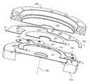
- FIG. 1illustrates a nano-imprinting press system in accordance with an embodiment
- FIG. 2Aillustrates a cross sectional view of a single-sided die set which may be incorporated into the nano-imprinting press system of FIG. 1 , in accordance with an embodiment
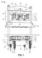
- FIG. 2Billustrates a cross sectional view of a double-sided die set which may be incorporated into the nano-imprinting press system of FIG. 1 , in accordance with an embodiment
- FIG. 3Ais a state diagram illustrating states of an imprinting operation, in accordance with an embodiment
- FIG. 3Bis a flow diagram illustrating a two phase pressing method, in accordance with an embodiment
- FIG. 3Cis a flow diagram illustrating a double-sided pressing method, in accordance with an embodiment
- FIG. 3Dis a flow diagram illustrating a pressing method, in accordance with an embodiment
- FIG. 4illustrates a cross sectional view of a portion of a double-sided die set in an open state, in accordance with an embodiment
- FIG. 5Aillustrates a cross sectional view of a portion of a double-sided die set in a first closing state, in accordance with an embodiment
- FIG. 5Billustrates an expanded cross sectional view of a portion of the double-sided die set depicted in FIG. 5A , in accordance with an embodiment
- FIG. 6Aillustrates a cross sectional view of a portion of a double-sided die set in a second closing state, in accordance with an embodiment
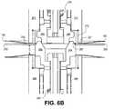
- FIG. 6Billustrates an expanded cross sectional view of a portion of the double-sided die set depicted in FIG. 6A , in accordance with an embodiment
- FIG. 7Aillustrates a cross sectional view of a portion of a double-sided die set transitioning from the second closing state to a third closed state, in accordance with an embodiment
- FIG. 7Billustrates an expanded cross sectional view of a portion of the double-sided die set depicted in FIG. 7A , in accordance with an embodiment
- FIG. 8Aillustrates a cross sectional view of a portion of a double-sided die set in a fourth closing state, in accordance with an embodiment
- FIG. 8Billustrates an expanded cross sectional view of a portion of the double-sided die set depicted in FIG. 8A , in accordance with an embodiment
- FIG. 9illustrates a cross sectional view of a portion of a double-sided die set in a closed state, in accordance with an embodiment
- FIG. 10Aillustrates a cross sectional view of a portion of a single-sided die set in closed state prior to imprinting, in accordance with an embodiment
- FIG. 10Billustrates an expanded cross sectional view of a portion of the single-sided die set depicted in FIG. 10A , in accordance with an embodiment
- FIG. 11Aillustrates a cross sectional view of a portion of a single-sided die set in the closed state while imprinting, in accordance with an embodiment
- FIG. 11Billustrates an expanded cross sectional view of a portion of the single-sided die set depicted in FIG. 11A , in accordance with an embodiment
- FIG. 12Aillustrates an isometric view of a single-sided embossing foil holder assembly, in accordance with an embodiment
- FIG. 12Billustrates cross-sectional views of the assembly in FIG. 12A , in accordance with an embodiment
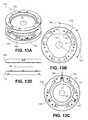
- FIG. 13Aillustrates an isometric view of a double-sided embossing foil holder assembly, in accordance with an embodiment
- FIG. 13Billustrates a bottom-up plan view of a top side of the assembly depicted in FIG. 13 A., in accordance with an embodiment
- FIG. 13Cillustrates a top-down plan view of a bottom side of the assembly depicted in FIG. 13A , in accordance with an embodiment
- FIG. 13Dillustrates a cross sectional view of the assembly depicted in FIG. 13A , in accordance with an embodiment
- FIG. 13Eillustrates an exploded isometric cross sectional view of the assembly depicted in FIG. 13A , in accordance with an embodiment
- FIG. 14Aillustrates a cross sectional view of a single-sided embossing foil holder mounted in a press system die, in accordance with an embodiment
- FIG. 14Billustrates a cross sectional view of the single-sided embossing foil holder of FIG. 13A when a press system is in a closed position, in accordance with an embodiment.
- the terms “over,” “under,” “between,” and “on” as used hereinrefer to a relative position of one member with respect to other members.
- one member disposed over or under another membermay be directly in contact with the other member or may have one or more intervening members.
- one member disposed between membersmay be directly in contact with the two members or may have one or more intervening members.
- a first member “on” a second memberis in contact with that second member.
- the relative position of one member with respect to other membersis provided assuming operations are performed relative to a substrate without consideration of the absolute orientation of the substrate.
- the terms “top” and “bottom”are to be understood as merely convenient labels describing only a relative physical relationship, and as such, “top” and “bottom” components may generally swap position while still achieving the same technical effect.
- the apparatus and methods discussed hereinmay be used with various types of disks.
- the apparatus and methodsdiscusses herein are used with a magnetic recording disk.
- the apparatus and methods discussed hereinmay be used with other types of digital recording disks, for example, a compact disk (CD), a digital versatile disk (DVD), and a magneto-optical disk.
- FIG. 1illustrates one embodiment of a press system 100 that incorporates one or more of the components as further described elsewhere herein.
- An upper portion of the press system 100includes top cross beam 120 , top die 102 , bottom die 104 , and press top base plate 106 .
- Top die 102 and bottom die 104are coupled by posts (e.g., posts 110 , 111 ).
- the base portion of each posthas a bushing (e.g., bushings 114 , 115 ).
- the top die 102also includes a top holder mount base 242 for receiving a top holder mount (not depicted in FIG. 1 .) to which a top embossing foil 150 is held.
- the bottom die 104includes a bottom holder mount base 142 for receiving a bottom holder mount (not depicted in FIG. 1 .) to which a bottom embossing foil (not shown in FIG. 1 ) is held.
- the bottom holder mount base 142is disposed above a bottom die holder base 146 and a bottom die holder base plate 148 .
- the top holder mount base 242may be similarly assembled over a holder base plate.
- a lower portion of the press system 100includes a gas actuator 160 disposed between the first press bottom base plate 107 and the second press bottom base plate 167 .
- the first press bottom base plate 107may be rigidly mounted relative to the press top base plate 106 (e.g., on opposing sides of a table) so that a linear displacement of the second press bottom base plate 167 relative to the base plates 106 , 107 is translated, via the main rods 109 , into a linear motion of the top die 102 relative to the bottom die 104 .
- a bottom cross beam 122is disposed below the second press bottom base plate 167 .
- Springs 162 , 163 , 161 , and 164on spring rods 130 , 131 , 132 , and 133 , compress the gas actuator 160 between the first press bottom base plate 107 and the second press bottom base plate 167 .
- the second press bottom base plate 167moves downward and away from the first press bottom base plate 107 . This expansion causes the top cross beam 120 to lower and displace the top holder mount base 242 and the bottom holder mount base 142 toward each other to be in one or more closed states.
- the press system 100may be configured for either single-sided imprinting or double-side imprinting by adapting the top die 102 and/or bottom die 104 .
- FIG. 2Aillustrates an enlarged cross sectional view of one embodiment of a single-sided die set which may be incorporated into the press system 100 .
- the cross-sectional axis a-a′is substantially aligned with the top cross beam 120 of FIG. 1 .
- bottom holder mount base 142is coupled to the bottom die holder base 146 in the bottom die 104 .
- a top die holder mount base 242is coupled to the top die base plate 246 in the top die 102 .
- a bottom embossing foil 251is disposed above a bottom press pad 280 of the bottom die 104 and coupled by the bottom holder mount 1210 to the bottom holder mount base 142 .
- the bottom press pad 280may include be one or more elastomeric layers that allow for a uniform press of nanoscopic imprinting features in the bottom embossing foil 251 against an embossable film of a recording media disk substrate 255 .
- a bottom rod 284extends through a center portion of the bottom die 104 .
- the bottom rod 284is sized to engage an inner diameter (ID) of the recording media disk substrate 255 .
- a bottom ball bushing 288surrounds the elongated portion of the bottom rod 284
- a bottom outer sleeve 290surrounds the bottom ball bushing 288 .
- the bottom outer sleeve 290 and the bottom rod 284combine to form a bottom mandrel with a bottom rod spring 285 disposed between the bottom outer sleeve 290 and an end of the bottom rod 284 distal from the recording media disk substrate 255 .
- the bottom outer sleeve 290is, in turn, disposed on a bottom mandrel spring 291 .
- the bottom holder mount base 142further includes a bottom standoff 243 which is configured to contact the top standoff 244 when the top and bottom dies 102 , 104 are brought into contact when the press system is in a closed state, as further described elsewhere herein.
- a top rod 294extends through a center portion of the top die 102 and is coupled to the top die 102 via a top mandrel spring 295 .
- FIG. 2Billustrates a cross sectional view of one embodiment of a double-sided die set which may be incorporated into the press system of FIG. 1 for the imprinting of both sides of a recording media.
- the cross-sectional axis a-a′is substantially aligned with the top cross beam 120 of FIG. 1 .
- the bottom die 104includes substantially the same components as described in FIG. 2A while the top die 102 includes additional components facilitating a second side of imprinting.
- the top mandrelis separated into a top outer sleeve and a top rod 294 having a top mating surface 296 .
- the top mating surface 296is configured to mate with a bottom mating surface 286 of the bottom rod 284 , as further described elsewhere herein.
- a top ball bushing 270surrounds an elongated portion of a top rod 294 with the top outer sleeve 271 surrounding the top ball bushing 270 .
- a top rod spring 275is disposed between the top outer sleeve 271 and an end of the top rod 294 distal from the top mating surface 296 .
- the top outer sleeve 271is, in turn, disposed on the top mandrel spring 295 .
- the top rod 294is therefore movable relative to the top outer sleeve 271 along a longitudinal mandrel axis as a function of the top rod spring 275 while the top outer sleeve 271 is also movable relative to the top die 102 as a function of the top mandrel spring 295 .
- a top embossing foil 150is disposed over a top press pad 276 of the top die 102 and coupled by the top holder mount 1350 to the top holder mount base 242 .
- the press pad 276may include be one or more elastomeric layers that allow for a uniform press of nanoscopic imprinting features in the top embossing foil 150 against an embossable film of a recording media disk substrate 255 .
- the top and bottom ball bushings 270 and 288hold the top/bottom rods 294 , 284 in precise alignment with the top/bottom outer sleeves 271 , 290 , respectively, to center embossing foils 150 , 251 with a longitudinal axis of the respective top/bottom rod. This allows for a concentricity to be established and maintained between the embossing foils 150 , 251 and the rods 294 , 284 .
- At least one of the top or bottom diesincludes an opening with a larger diameter than the outer diameter of the outer sleeve to allow radial movement of a mandrel relative to the die through which the mandrel passes as the top and bottom rods are aligned to a common longitudinal mandrel axis upon closing the press.
- the concentricity of the sleeves to the rods and the concentricity of the foils to the sleevesensure that the recording media disk substrate 255 engaged by a rod is concentric with both the top and bottom embossing foils.
- either or both of the top and bottom dies 102 , 104may further include a chamber volume which may be pressurized to displace a piston relative to the die assembly in which the piston is housed.
- the piston 278is disposed within the top die 102 to provide a force against a top press pad 276 through which an imprinting force may be applied to the top embossing foil 150 , as further described elsewhere herein.
- FIG. 3is a state diagram illustrating a nano-imprinting operation 300 , in accordance with one exemplary embodiment.
- the states depicted in the nano-imprinting operation 300are performed during one pressing cycle (i.e., from open to closed to open).
- FIGS. 4-9illustrate cross sectional views of a portion of a double-sided die set in the states of FIG. 3 . While FIG. 3 is described in the context of double-sided imprinting, many or all of the same states described may be performed during a single-sided imprinting operation.
- the nano-imprinting operation 300maintains a positive pressure against the aligned workpiece throughout the duration of the pressing operation (e.g., throughout all closing states) to establish and preserve a centering of the workpiece relative to both the top and bottom dies 102 , 104 .
- the nano-imprinting operation 300begins at the open state 301 with first receiving a workpiece into a press system.
- the bottom rod spring 285when in an open state with the opposing dies spaced apart from one another, the bottom rod spring 285 is in a relatively decompressed state which extends the bottom rod 284 above the bottom outer sleeve 290 to receive the recording media disk substrate 255 .
- the bottom outer sleeve 290is similarly displaced outward relative to the bottom holder mount base 142 by the compressive force of the bottom mandrel spring 291 .
- the bottom outer sleeve 290includes a notch 230 which engages a cam (not depicted) to position the bottom outer sleeve 290 relative to the bottom holder mount base 142 .
- This outward extension of the bottom outer sleeve 290is set by the cam's position relative to the notch 230 to form a bottom doming 228 in the bottom embossing foil 251 .
- Lifting the bottom outer sleeve 290creates a dome-like shape (bottom doming 228 ) along an inner radial distance, or center, of the bottom embossing foil 251 .
- the dome in the center portion of the bottom embossing foil 251assists in separating the recording media disk substrate 255 from the surface of bottom embossing foil 251 when the press returns from a closed state to the open state after completing an imprinting process.
- the top rod spring 275when in an open state, the top rod spring 275 is in a relatively decompressed state.
- the top rod 294is displaced beyond the top outer sleeve 271 and the top holder mount base 242 , in preparation for receiving the bottom rod 284 .
- the top outer sleeve 271extends outward from the top holder mount base 242 in response to the compressive force of the top mandrel spring 295 .
- the top outer sleeve 271also includes a notch 231 which engages a cam (not depicted) to position the top outer sleeve 271 relative to the top holder mount base 242 .
- This outward extension of the top outer sleeve 271is set by the cam's position relative to the notch 231 to form a top doming 233 in the top embossing foil 150 .
- the cams in the top and bottom dies 102 , 104may also set a controllable amount of spring pre-load in the mandrel springs 291 , 295 .
- Cam-notch arrangementsmay also be employed to set a controllable amount of spring pre-load into either or both of the top and bottom rod springs 275 , 285 .
- the four opposing springsare preloaded asymmetrically.
- the bottom rod spring 285is preloaded to a force of 2.1 lbs
- the bottom mandrel spring 291is preloaded to 9.3 lbs
- the top rod spring 275is preloaded to 1.7 lbs
- the top mandrel spring 295is preloaded to 12.5 lbs.
- the recording media disk substrate 255is disposed onto a male conical surface 287 configured to have a range of outer diameters (OD) inclusive of the inner diameter (ID) of the recording media disk substrate 255 to hold the substrate 255 (e.g., by gravity).
- the orientation of substrate 255may be non-orthogonal to the top mandrel longitudinal axis 223 or bottom mandrel longitudinal axis 224 .
- the recording media disk substrate 255may be centered about the bottom mandrel longitudinal axis 224 but still have a radial axis non-orthogonal to the bottom mandrel longitudinal axis 224 .
- the top mandrel longitudinal axis 223may also be misaligned relative to the bottom mandrel longitudinal axis 224 .
- closing forceis applied (e.g., via the gas actuator 160 ) which linearly displaces the top and bottom dies 102 , 104 toward each other.
- the components of the press system 100then undergo a sequence of configurations, referred to herein as “closing states” in response to the displacement of the top and bottom dies 102 , 104 .
- the physical characteristics of particular closing statesare dependent upon the relative dimensions, positions and force relationships between the components of the top and bottom dies 102 , 104 .
- FIG. 5Aillustrates an expanded cross sectional view of a portion of a double-sided die set in the closing state 305 , in accordance with an embodiment.
- At least one of the bottom and top rods 284 , 294include a female conical or tapered end surface which couples to a male end surface of the other rod to generate a radial alignment force between the mating rod surfaces as the press continues to close and springs 275 , 285 , 291 and 295 apply a force along the longitudinal mandrel axis opposing the closing force.
- the bottom mating surface 286forms a female conical surface spanning a range of inner diameters (ID) inclusive of the outer diameter (OD) of the non-conical top mating surface 296 .
- the conical shape of the bottom mating surface 286displaces either or both of the bottom and top rods 284 , 294 in a radial direction (orthogonal to the longitudinal mandrel axis) within the die clearance to align the top mandrel longitudinal axis 223 with the bottom mandrel longitudinal axis 224 and form the common longitudinal mandrel axis 229 .
- a male conical mating surfacesuch as that depicted in FIG.
- closing state 305centers the alignment of the embossing foils 150 , 251 about the common longitudinal mandrel axis 229 .
- the bottom outer sleeve 290is further coupled to a bottom shoulder ring 292 .
- the bottom shoulder ring 292may be a collar machined into a portion of the bottom outer sleeve 290
- the bottom shoulder ring 292is a separate component such that the bottom outer sleeve 290 becomes an assembly.
- An outer diameter of the bottom shoulder ring 292is substantially equal to an inner diameter of the bottom embossing foil 251 .
- the bottom embossing foil 251annular in shape, has an inner circumferential surface directly bonded to the bottom shoulder ring 292 .
- the bottom shoulder ring 292centers the bottom embossing foil 251 to a longitudinal axis of the bottom outer sleeve 290 (which is aligned with the longitudinal mandrel axis 229 ).
- the bottom outer sleevefurther includes a radial support surface 226 extending radially from the bottom shoulder ring 292 to an outer diameter larger than the inner diameter of the bottom embossing foil 251 .
- the radial support surface 226is configured to be in direct contact with a back surface of an inner radial portion of the bottom embossing foil 251 .
- radial support surface 226is directly bonded to a portion of the back surface of the bottom embossing foil 251 .
- the bottom shoulder ring 292extends along the longitudinal mandrel axis 229 beyond the radial support surface 226 by an amount, H.
- the distance His less than the thickness of the bottom embossing foil 251 .
- the top outer sleeve 271is coupled to a top shoulder ring 272 to form a top sleeve assembly similar to the bottom sleeve assembly.
- the top outer sleeve 271centers the top embossing foil 150 to a longitudinal axis of the top outer sleeve 271 (which is aligned with the longitudinal mandrel axis 229 ).
- the top outer sleeve 271further includes a radial support surface 227 extending radially from the top shoulder ring 272 to an outer diameter larger than the inner diameter of the top embossing foil 150 .
- the radial support surface 227is in direct contact with a back surface of an inner portion of the top embossing foil 150 and, in the exemplary embodiment, is directly bonded to the back surface of the top embossing foil 150 .
- the top shoulder ring 272extends along the longitudinal mandrel axis 229 beyond the radial support surface 227 , preferably by an amount less than a thickness of the top embossing foil 150 .
- the shoulder rings 272 , 292may be of a material different than that of the radial support surfaces 226 , 227 .
- the shoulder ring(s)is of a first material having a different coefficient of thermal expansion than the material of the radial support surface(s), thereby enabling the shoulder ring to be assembled into the outer sleeve(s) at a first temperature and affixed upon reaching a second temperature, different than the first temperature (e.g., press system operating temperature).
- the bottom shoulder ring 292is an aluminum ring pressure fit to an inner circumference of the bottom outer sleeve 290 . After the pressure fitting, the bottom shoulder ring 292 and the radial support surface may then be machined at the same time to form a contiguous machined surface.
- the top shoulder ring 272may similarly form a contiguous machined surface with the radial support surface 227 .
- the nano-imprinting operation 300proceeds to the closing state 310 .
- the opposing rod springs and mandrel springshave different spring strengths which serve to asymmetrically displace the first and second mandrels from an open state to various sequential closed states in response to a closing force of the press which displaces the top and bottom dies 102 , 104 toward each other.
- a first rod springis compressed before a second rod spring compresses so that a first outer sleeve applies pressure to the workpiece against the rod carrying the workpiece.
- the shape of the first outer sleevee.g.
- height of a shoulder ringis such that the first outer sleeve causes a domed inner portion (ID) of a first embossing foil to directly contact the workpiece and level the workpiece to be orthogonal to the common mandrel axis.
- the bottom rod spring 285applies a larger spring force than the top rod spring 275 such that the top rod spring 275 compresses before the bottom rod spring 285 .
- the top rod 294retracts in response to the press closing force until the top outer sleeve 271 begins to apply an opposing force against the recording media disk substrate 255 .
- FIG. 6Billustrates an expanded cross sectional view of a portion of a double-sided die set in the closing state 310 .
- a gap, Gremains between the recording media disk substrate 255 and the bottom embossing foil 251 .
- the top shoulder ring 272has a height slightly less than the thickness of the top embossing foil 150 , the force provided by the top outer sleeve 271 is applied to the recording media disk substrate 255 through the portion of the top embossing foil 150 that is bonded to the upper radial support surface 227 .
- the inner circumference of the top embossing foil 150contacts the recording media disk substrate 255 along a radial length determined by an amount of top doming 233 present in the top embossing foil 150 .
- the opposing force applied by the top outer sleeve 271 against the recording media disk substrate 255serves to orient and level a radial axis of the substrate 255 .
- the opposing force applied by the top outer sleeve 271 against the recording media disk substrate 255orients a longitudinal axis of the substrate 255 to be substantially parallel with the longitudinal mandrel axis 229 .
- the opposing force applied by the top outer sleeve 271 while in the closing state 310is a function of the relative spring strengths of the top mandrel spring 295 , the bottom mandrel spring 291 , the top rod spring 275 and the bottom rod spring 285 . While it is the relative relationship of spring strengths which enables the advantageous asymmetrical closing of the press system described herein, when the exemplary embodiment reaches the closing state 310 , the top rod spring 275 provides a force of approximately 1.9 lbs, while the bottom rod spring 285 provides a force of approximately 2.1 lbs. As such, the bottom rod spring 285 remains in the preloaded state while the top rod spring 275 is in a retracted state when the magnetic recording media disk substrate 255 first contacts the top embossing foil 150 .
- the nano-imprinting operation 300proceeds to the closing state 315 in response to the press closing force.
- the second rod springis compressed to displace the rod carrying the substrate relative to a second outer sleeve to eliminate the gap between the workpiece and the second outer sleeve.
- an inner portion of the second embossing foildirectly contacts the workpiece.
- the second outer sleevemay directly contact the workpiece or apply a pressure against the workpiece through another intervening member.
- the top and bottom outer sleeves 271 , 290are abutting with the top and bottom rods 284 and 294 in a fully retracted position.
- the top rod spring 275provides a force of approximately 1.9 lbs
- the bottom rod spring 285provides a force of approximately 3.1 lbs.
- the force in the bottom rod spring 285increases from the preloaded state.
- the nano-imprinting operation 300proceeds to the closing state 320 in response to the press closing force.
- the second outer sleeveapplies a force against the workpiece which opposes the force applied by the first outer sleeve and the weaker of the mandrel springs becomes the third spring to compress.
- a first outer sleeveis displaced until the doming in a first of the embossing foils is removed, flattening the first embossing foil coupled to the first outer sleeve. Sequentially removing the doming based on relative mandrel spring strengths may be advantageously more controllable than removing both the top and bottom doming concurrently.
- FIGS. 8A and 8Billustrate cross sectional views of a portion of a double-sided die set in the closing state 320 , in accordance with an embodiment.
- the bottom doming 288is eliminated such that the bottom embossing foil 251 is in complete contact with the bottom press pad 280 while the top doming 233 remains.
- the top rod spring 275 forceremains at approximately 1.9 lbs (retracted top rod state), while the bottom rod spring 285 force remains at approximately 3.1 lbs (retracted bottom rod state).
- the top mandrel spring 295 forceincreases from the open state preload force of 12.5 lbs to approximately 13.5 lbs while the bottom mandrel spring 291 increases from the open state preload force of 9.3 lbs to a force of approximately 10.8 lbs.
- FIG. 9illustrates a cross sectional view of a portion of a double-sided die set in the closed state 325 , in accordance with an embodiment.
- top doming 233is reduced while the bottom embossing foil 251 is flat (i.e., bottom doming 288 is removed) while the top and bottom sleeves 271 and 290 are abutted against inner radius of the recording media disk substrate 255 .
- imprintingmay or may not occur upon advancing to the closed state 325 as a function of whether or not all of the doming in both embossing foils is eliminated upon reaching the closed state 325 .
- imprinting of the workpieceoccurs at the closing states 320 and 325 as the second embossing foil is flattened.
- the force closing the pressis the force that will imprint the workpiece and the nano-imprinting operation 300 advances along the dotted line in FIG. 3 to the open state 301 .
- a two phase pressing method 340begins at operation 341 with a magnetic recording disk received on a first die of a die set while the die set is in an open state (e.g., the open state 301 ).
- the die setis closed in the first phase where a first embossing foil is in contact with the workpiece and a second embossing foil is spaced apart from the magnetic recording disk by the doming in the second foil (e.g., the closed state 325 ).
- a piston disposed within a dieis displaced while the die set is closed (e.g., the closed state 330 ) to reduce the doming remaining in the second embossing foil. Once the dome and associated gap is eliminated, the piston presses the embossing foil against the recording disk at operation 344 .
- the stoppercan be set to prevent macroscopic displacement of the closing dies from imprinting the recording media disk substrate 255 .
- the stopperdefines a predetermined gap associated with the desired amount of doming to retain in the second embossing foil when the die press is closed.
- the stopperenables precise control in the reduction of the doming in the second embossing foil without over-compressing the workpiece (e.g., compressing the press pad 280 ).
- the force imprinting the workpieceis distinct from the force closing the press.
- the stopperalso permits the relatively large die displacement required between an open state suitable for loading and unloading a workpiece to be rapidly traversed in a first “closing” phase of the nano-imprinting operation 300 .
- a second “closed” phase of the nano-imprinting operation 300allows for sub-micron precision with a relatively slower traversal of a distance that is at least an order of magnitude smaller than for the closing phase.
- separating the nano-imprinting operation 300 into these two phasesmay be practiced even where the particular closing states 305 - 325 are not employed.
- a stoppermay still be used as described herein.
- the stoppermay be one or more of a mechanical hard stop or a die displacement controller reactive to an optical sensor, electrical sensor, or a mechanical sensor.
- a mechanical hardstopmany variations are possible.
- opposing standoffsmay be machined into the top and bottom dies 102 , 104 to be in substantial alignment with each other and proximate to an outer edge of the magnetic recording disk when the die set in a closed position.
- FIG. 10Aillustrates a cross sectional view of a portion of a single-sided die set in the closed state 325 where the bottom standoff 243 makes contact with the top standoff 244 .
- the standoffs 243 and 244make contact and serve as a mechanical stopper to halt the displacement of the top and bottom dies 102 , 104 while the embossing foil 251 is still spaced apart from a magnetic recording media disk substrate 255 by a predetermined gap.
- FIG. 10Bprovides an expanded cross sectional view further illustrating that the piston 278 , until subsequently actuated, is uniformly spaced apart from the recording media disk substrate 255 . A non-zero gap is also present between the embossing foil 251 and the recording media disk substrate 255 .
- an imprinting pistonis actuated to advance the nano-imprinting operation 300 from the closed state 325 to the closed state 330 .
- either or both diesmay include one or more imprinting pistons which may be moved relative to the first and second die halted by the stopper to press an embossing foil against the workpiece.
- the imprinting piston(s)may be activated by pressurizing a volume chamber with a gas or liquid after the die set is stopped in the closed position.
- the volume chamberis to be pressurized with a force less than a force holding the die set in the closed position.
- FIG. 11Aillustrates a cross sectional view of a portion of a double-sided die set in the closed state 330 , in accordance with an embodiment.
- the top piston 278 in the top die 102is moved toward the bottom die 104 .
- FIG. 11Billustrates an expanded cross sectional view of the single-sided die set depicted in FIG. 11A .
- the piston 278traverses the distance, P, to press the embossing foil 251 against the magnetic recording media disk substrate 255 to imprint features onto the substrate 255 .
- the distance Pis at least equal to the doming which remains after the die set is closed (e.g., between approximately 0.1 mm and 0.3 mm).
- the distance, Pmay vary as dependent on factors such as whether opposing pistons are employed and whether imprinting pads are employed.
- an imprinting pistonis disposed in both the top and bottom dies 102 , 104 such that a first volume is pressurized on a side of a first piston opposite a first side of the workpiece and a second volume is pressurized on a side of a second piston opposite a second side of the workpiece to displace the first and second pistons in opposing directions toward respective embossing foils.
- Each of the pistonsmay travel a distance, P, which is at least equal to an amount of doming between the embossing foil and the workpiece which remains after the die set is closed (e.g., between approximately 0.1 mm and 0.3 mm).
- the nano-imprinting operation 300advances from the closed state 330 back to the open state 301 , as depicted in FIG. 3 .
- the imprinting pistons(if employed) may be returned to the recessed home position and the closing force removed or reversed to separate the die set.
- the states depicted in FIG. 3are sequentially reversed as the press closing force provided by the gas actuator 160 is removed. Reversal of the states in the press operation 300 enables a controlled separation of the embossing foils from the workpiece in a manner which maintains good fidelity of the imprinted features.
- Return springs in addition to the mandrel and rod springsmay be employed or other driving forces may be employed to advance from the closed state 330 to the open state 301 .
- the imprinted workpiecemay be unloaded.
- FIG. 12Aillustrates an isometric view of an assembly 1200 which includes a single-sided embossing foil holder 1201 and the holder mount 1210 , in accordance with an embodiment.
- the assembly 1200may be employed to affix an embossing foil to a die in a nano-imprinting press system, such as the exemplary press system 100 .
- FIG. 10 Billustrates the assembly 1200 mounted to the bottom die 104 .
- the holder mount 1210is rigidly affixed to the bottom die 104 , the foil holder 1201 is affixed to the holder mount 1210 , and the bottom embossing foil 251 is clamped between the foil holder 1201 and a portion of the bottom die 104 (e.g., the bottom press pad 280 ).
- the thickness of the foil holder 1201should be no greater than the thickness of the recording media disk substrate 255 .
- the foil holder 1201is annular in shape to surround a longitudinal mandrel axis 229 when mounted into a press system.
- the foil holder 1201has an inner diameter 1202 which is smaller than the outer diameter of the embossing foil 251 that is to be retained by the assembly 1200 .
- the foil holder 1201is affixed to the holder mount 1210 at a radial distance beyond an outer diameter of the embossing foil 251 such that the foil holder 1201 forms a flange overlapping an outer circumference of the bottom embossing foil 251 .
- the foil holder 1201is affixed to the holder mount 1210 with a plurality of screws 1205 which pass through openings 1206 .
- the openings 1207may be similarly utilized to affix the holder mount 1210 to a die.
- FIG. 12Billustrates views of the assembly 1200 along the b-b′ cross-section.
- the holder mount 1210is annularly shaped such that the b-b′ cross section forms two cross-sectional faces, one of which is illustrated in an expanded view.
- the holder mount 1210has an inner circumferential surface 1211 defining an inner diameter 1212 of the holder mount 1210 .
- the inner diameter of the holder mountis larger than the outer diameter of the embossing foil 251 such that a gap, G, is formed between the outer circumference of the embossing foil 251 and the inner circumference of the holder mount 1210 .
- the gap Gis approximately 0.1 mm so that, of the components in the assembly 1200 , only the foil holder 1201 contacts the embossing foil 251 .
- the foil holder 1201presses against an outer surface of the embossing foil to apply a clamping force toward a holder mount base (e.g., disposed in the bottom die 104 as depicted in FIG. 10B ).
- FIG. 13Aillustrates an isometric view of an assembly 1300 which includes a bottom holder mount 1310 and a top holder mount 1350 which may be employed to couple two embossing foils to a die set in a double-sided press system, such as the exemplary press system 100 .
- FIGS. 13B and 13Cillustrate plan views of the double-sided embossing foil holder of FIG. 13A .
- FIG. 13Billustrates a “bottom-up” plan view of an overlying top holder mount (i.e., looking up from a workpiece to be pressed) while
- FIG. 13Cillustrates a “top-down” plan view of an underlying bottom holder mount (i.e., looking down from a workpiece to be pressed).
- a top foil holder 1301includes a plurality of holder tabs 1302 extending radially inward from the top holder mount 1350 to reach an inner diameter 1303 which is smaller than the outer diameter 151 of the top embossing foil 150 .
- the holder tabs 1302overlap a portion of the top embossing foil 150 .
- the inner diameter of the top holder mount 1350is larger than the outer diameter 151 of the top embossing foil 150 (e.g., by approximately 0.1 mm).
- the holder tabs 1302form first arc segments along the circumference of the top foil holder 1301 to clamp first portions of an outer circumference of the top embossing foil 150 against an underlying surface of the top die 102 when the top holder mount 1350 is affixed to a holder mount base (e.g., holder mount base 242 illustrated in FIG. 2B ).
- a holder mount basee.g., holder mount base 242 illustrated in FIG. 2B .
- the exemplary bottom foil holder embodiment depicted in FIG. 13Cincludes a plurality of holder tabs 1325 extending radially inward from the bottom holder mount 1310 to reach an inner diameter 1327 which is smaller than the outer diameter 252 of the bottom embossing foil 251 .
- the holder tabs 1325overlap a portion of the bottom embossing foil 251 .
- the inner diameter of the bottom holder mount 1310is larger than the outer diameter 252 of the bottom embossing foil 251 (e.g., by approximately 0.1 mm).
- the holder tabs 1325form second arc segments along the circumference of the bottom holder mount 1310 to clamp second portions of an outer perimeter of the bottom embossing foil 251 against a surface of the bottom die 104 when the bottom holder mount 1310 is affixed to the bottom die 104 .
- the top foil holder 1301has an annular shape and a radial width which varies with angular position about the longitudinal mandrel axis 229 while the bottom foil holder is comprised of the holder tabs 1325 which are physically independent of each other and each separately affixed to the bottom holder mount 1310 .
- the holder tabs 1325are disposed the bottom holder mount 1310 at angular positions corresponding to where the first embossing foil holder, as affixed to the top holder mount 1350 , has the smallest radial width.
- the combined arc segment length of the holder tabs 1302is preferably approximately equal to the combined arc segment length of the holder tabs 1325 . While the number of tabs for the top and bottom foil holders may vary while still achieving approximately equal arc segment lengths, the number should be sufficiently great to adequately distribute the foil clamping force along the outer circumference of the foils.
- the number of holder tabs 1302is equal to the number of holder tabs 1325 , with each of the holder tabs 1302 , 1325 having a center 1304 at an angular position about the longitudinal mandrel axis 229 which is separated by an angle ⁇ 1 approximately equal to 120 degrees with the holder tabs 1302 having centers offset by approximately 60 degrees from the centers of the holder tabs 1325 .
- FIG. 13Eillustrates an exploded isometric cross-sectional view of the assembly depicted in FIGS. 13A , 13 B and 1 C, in accordance with an embodiment.
- a longitudinal thickness, T 1of each of the plurality of holder tabs 1302 is approximately equal to the longitudinal thickness, T 2 , of the each of the plurality of holder tabs 1325 .
- the longitudinal thicknesses T 1 and T 2are less than a longitudinal thickness T 3 of the magnetic recording media disk substrate 255 .
- the top and bottom foil holdersinterdigitate to form an annulus of an approximately constant thickness.
- Such an arrangementdistributes pressing forces uniformly along the outer perimeters of the embossing foils without distorting the embossing foils.
- the thicknesses and geometries described hereinpresent substantially flush surfaces to the recording media disk substrate 255 for good imprinting performance.
- FIGS. 13A , 13 C and 13 Efurther illustrate a support member 1375 configured to be disposed around an outer perimeter of a magnetic recording disk and between the top and bottom embossing foils 150 , 251 when a die set is closed.
- the support member 1375may serve as a spacer to prevent a detrimental collapse of the embossing foils adjacent to the outer perimeter of the magnetic recording disk.
- the support member 1375is affixed to the bottom holder mount 1310 with edges adjacent to the edges of the holder tabs 1325 .
- the support member 1375has a thickness, T 4 , greater than the thickness T 2 of the holder tabs 1325 .
- the two componentsare unified into a monolithic piece which serves both foil holding functions and foil spacing functions.
- the edge 1304is spaced apart from, but adjacent to, the edge 1327 . Because the first and second arc segments formed by the holder tabs 1302 and 1325 are complementary, the holder tabs 1302 interdigitate with the holder tabs 1325 when the top and bottom dies 102 , 104 are brought together (e.g., the exploded view of FIG. 13D is collapsed).
- the assembly 1300is affixed to the press system 100 to perform a double-sided pressing method 350 , as depicted in FIG. 3C .
- the method 350begins with an outer circumference of a first embossing foil clamped to a first die with a plurality of first tabs at operation 351 .
- the top embossing foil 150may be clamped to the top die 102 with the holder tabs 1302 .
- an outer circumference of a second embossing foilis clamped to a first die with a plurality of second tabs.
- the bottom embossing foil 251may be clamped to the bottom die 104 with the holder tabs 1325 .
- a magnetic recording diskis received into the press system at operation 355 (e.g., the magnetic recording media disk substrate 255 is received into the press system 100 ).
- the pressis closed around the magnetic recording disk by interleaving the plurality of first tabs with the plurality of second tabs. For example, as the closing state 325 ( FIG. 3A ) is reached, the holder tabs 1325 interdigitate with the holder tabs 1302 as depicted in FIG. 13D .
- the recording media diskis then pressed to imprint both a front side and a back side.
- the piston 278may be actuated during the closed state 330 as a second phase of the pressing method 350 .
- the embossing foil employed by a press systemis coupled to a die in a manner which allows the embossing foil to expand radially during an imprinting process. Allowing such radial expansion can reduce buckling of the embossing foil and reduce waviness in the features imprinted into a recording media disk.
- an embossing foil holdersuch as any of those described in the context of assemblies 1200 and 1300 , is coupled to a die which clamps a first portion of the embossing foil in a manner which still allows the clamped foil portion to move in a radial direction relative to the embossing foil holder.
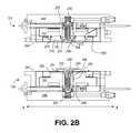
- FIG. 14Aillustrates a cross-sectional view of the single-sided embossing foil holder 1201 mounted in a press system die, in accordance with an embodiment.
- the press systemis in an open state with the bottom rod 284 holding a recording media disk substrate 255 and the bottom outer sleeve 290 extended away from the bottom press pad 280 to form the doming 288 .
- at least a portion of an inner circumference of the embossing foilis rigidly affixed and concentric to the bottom outer sleeve 290 to prohibit radial movement of the embossing foil relative to the bottom outer sleeve 290 .
- FIG. 14Aillustrates a cross-sectional view of the single-sided embossing foil holder 1201 mounted in a press system die, in accordance with an embodiment.
- the press systemis in an open state with the bottom rod 284 holding a recording media disk substrate 255 and the bottom outer sleeve 290 extended away from the bottom press pad
- the embossing foil holder 1201is rigidly affixed to the holder mount 1210 with the holder mount 1210 sized to have an inner diameter larger than the outer diameter of the bottom embossing foil 251 .
- the effect of such a sizingis annotated in FIG. 14A as the gap, G 1 , between the outer edge of the bottom embossing foil 251 and the inner edge of the holder mount 1210 .
- the inner surface of the holder mount 1210becomes a sidewall of the bottom die 104 adjacent to the bottom embossing foil 251 .
- the gap G 1 between the sidewall of the bottom die 104 and the bottom embossing foil 251provides room for the bottom embossing foil 251 to move or slide radially towards the holder mount 1210 .
- the gap, G 1will nominally be at least 0.05 mm and likely more as a result of the doming 288 .
- a spring clamping assemblyis employed to allow the clamped foil portion to move in a radial direction. While a variety of spring clamping assemblies are possible, in the depicted embodiment the holder mount 1210 is affixed to the bottom die 104 with a coil spring 1481 . The coil spring 1481 is compressed between the screw 1205 mounted to the bottom die 104 and the holder mount 1210 (or embossing foil holder 1201 since the holder is rigidly attached to the mount 1210 ). The screw 1205 may be adjusted to set tensioning of the foil holder 1201 to achieve a predetermined clamping force of the bottom embossing foil 251 against the bottom die 104 (e.g., the bottom press pad 280 ).
- the clamping forceis substantially parallel to the longitudinal mandrel axis 229 .
- the clamping forceis dependent on a number of factors, such as the friction coefficients of the embossing foil 251 , the foil holder mount 1210 and the bottom press pad 280 .
- the clamping forceranges between approximately 5 N and 30 N.
- Each of the screws 1205 depicted in FIG. 12Amay be mounted with the coil spring 1481 in the manner depicted in FIG. 14A to provide a plurality of coil springs spaced apart by an angular distance to provide the predetermined embossing foil clamping force.
- the 6 screws 1205 depicted in FIG. 12Aare each mounted with the coil spring 1481 to provide a total clamping force between 10 and 20 N.
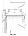
- FIG. 14Billustrates a cross-sectional view of the single-sided embossing foil holder of FIG. 14A when a press system is in a closed position, in accordance with an embodiment.
- the recording media disk substrate 255is now against the bottom embossing foil 251 and the bottom embossing foil 251 is expanded radially relative to the foil holder 1201 and the holder mount 1210 so that the gap G 1 is reduced to the gap G 2 .
- Double-side imprinting embodimentsmay also provide a clamping force which allows an outer circumference of an embossing foil to expand radially.
- the assembly 1300as depicted in FIGS. 13A-13E is readily adapted to allow radial foil expansion by mounting the top and bottom holder mounts with a spring tensioning assembly in a manner similar to that described for a single-sided press system.
- each of the holder tabs 1302may be mounted to the top holder mount 1350 with coil springs 1481 to provide a predetermined clamping force which allows the outer circumference of the top embossing foil 150 to slide against the top die 102 towards the holder tabs 1302 and top holder mount 1350 .
- Each of the holder tabs 1325may be mounted to the bottom holder mount 1310 with coil springs 1481 to provide a predetermined clamping force.
- FIG. 3Ddepicts a pressing method 375 which begins with clamping the embossing foil to a least a first die using a spring tensioned clamp (e.g., employing coil springs 1481 ) at operation 376 .
- a spring tensioned clampe.g., employing coil springs 1481
- FIG. 3Ddepicts a pressing method 375 which begins with clamping the embossing foil to a least a first die using a spring tensioned clamp (e.g., employing coil springs 1481 ) at operation 376 .
- a magnetic recording diskis received in a die press.
- the foilis pressed against the magnetic recording disk to form a discrete track recording pattern and the foil is allowed to expand by the spring tensioned clamp.
- the die pressis then unloaded at operation 379 .
- the nano-imprinting press systems and imprinting methods discussed hereinmay be used to fabricate pixel arrays for flat panel displays.
- an embossable materialmay be disposed above a base structure of, for example, an indium tin oxide (ITO) layer on top of a substrate.
- the nano-imprinting apparatus and methods discussed hereinmay be used to fabricate lasers.
- embossable material areas patterned by the embossing foilsare used as a mask to define laser cavities for light emitting materials.
- the apparatus and methods discussed hereinmay be used in other applications, for example, the production of multiple layer electronic packaging, the production of optical communication devices, and contact/transfer printing.
Landscapes
- Engineering & Computer Science (AREA)
- Mechanical Engineering (AREA)
- Manufacturing Of Magnetic Record Carriers (AREA)
Abstract
Description
Claims (16)
Priority Applications (2)
| Application Number | Priority Date | Filing Date | Title |
|---|---|---|---|
| US12/614,343US8496466B1 (en) | 2009-11-06 | 2009-11-06 | Press system with interleaved embossing foil holders for nano-imprinting of recording media |
| US13/929,390US9339978B1 (en) | 2009-11-06 | 2013-06-27 | Press system with interleaved embossing foil holders for nano-imprinting of recording media |
Applications Claiming Priority (1)
| Application Number | Priority Date | Filing Date | Title |
|---|---|---|---|
| US12/614,343US8496466B1 (en) | 2009-11-06 | 2009-11-06 | Press system with interleaved embossing foil holders for nano-imprinting of recording media |
Related Child Applications (1)
| Application Number | Title | Priority Date | Filing Date |
|---|---|---|---|
| US13/929,390DivisionUS9339978B1 (en) | 2009-11-06 | 2013-06-27 | Press system with interleaved embossing foil holders for nano-imprinting of recording media |
Publications (1)
| Publication Number | Publication Date |
|---|---|
| US8496466B1true US8496466B1 (en) | 2013-07-30 |
Family
ID=48808631
Family Applications (2)
| Application Number | Title | Priority Date | Filing Date |
|---|---|---|---|
| US12/614,343Expired - Fee RelatedUS8496466B1 (en) | 2009-11-06 | 2009-11-06 | Press system with interleaved embossing foil holders for nano-imprinting of recording media |
| US13/929,390Expired - Fee RelatedUS9339978B1 (en) | 2009-11-06 | 2013-06-27 | Press system with interleaved embossing foil holders for nano-imprinting of recording media |
Family Applications After (1)
| Application Number | Title | Priority Date | Filing Date |
|---|---|---|---|
| US13/929,390Expired - Fee RelatedUS9339978B1 (en) | 2009-11-06 | 2013-06-27 | Press system with interleaved embossing foil holders for nano-imprinting of recording media |
Country Status (1)
| Country | Link |
|---|---|
| US (2) | US8496466B1 (en) |
Cited By (70)
| Publication number | Priority date | Publication date | Assignee | Title |
|---|---|---|---|---|
| US8828566B2 (en) | 2010-05-21 | 2014-09-09 | Wd Media (Singapore) Pte. Ltd. | Perpendicular magnetic recording disc |
| US8859118B2 (en) | 2010-01-08 | 2014-10-14 | Wd Media (Singapore) Pte. Ltd. | Perpendicular magnetic recording medium |
| US8867322B1 (en) | 2013-05-07 | 2014-10-21 | WD Media, LLC | Systems and methods for providing thermal barrier bilayers for heat assisted magnetic recording media |
| US8877359B2 (en) | 2008-12-05 | 2014-11-04 | Wd Media (Singapore) Pte. Ltd. | Magnetic disk and method for manufacturing same |
| US8908315B2 (en) | 2010-03-29 | 2014-12-09 | Wd Media (Singapore) Pte. Ltd. | Evaluation method of magnetic disk, manufacturing method of magnetic disk, and magnetic disk |
| US8941950B2 (en) | 2012-05-23 | 2015-01-27 | WD Media, LLC | Underlayers for heat assisted magnetic recording (HAMR) media |
| US8947987B1 (en) | 2013-05-03 | 2015-02-03 | WD Media, LLC | Systems and methods for providing capping layers for heat assisted magnetic recording media |
| US8951651B2 (en) | 2010-05-28 | 2015-02-10 | Wd Media (Singapore) Pte. Ltd. | Perpendicular magnetic recording disk |
| US8980076B1 (en) | 2009-05-26 | 2015-03-17 | WD Media, LLC | Electro-deposited passivation coatings for patterned media |
| US8993134B2 (en) | 2012-06-29 | 2015-03-31 | Western Digital Technologies, Inc. | Electrically conductive underlayer to grow FePt granular media with (001) texture on glass substrates |
| US8995078B1 (en) | 2014-09-25 | 2015-03-31 | WD Media, LLC | Method of testing a head for contamination |
| US9001630B1 (en) | 2011-03-08 | 2015-04-07 | Western Digital Technologies, Inc. | Energy assisted magnetic recording medium capable of suppressing high DC readback noise |
| US9005782B2 (en) | 2008-03-30 | 2015-04-14 | WD Media, LLC | Magnetic disk and method of manufacturing the same |
| US9025264B1 (en) | 2011-03-10 | 2015-05-05 | WD Media, LLC | Methods for measuring media performance associated with adjacent track interference |
| US9029308B1 (en) | 2012-03-28 | 2015-05-12 | WD Media, LLC | Low foam media cleaning detergent |
| US9028985B2 (en) | 2011-03-31 | 2015-05-12 | WD Media, LLC | Recording media with multiple exchange coupled magnetic layers |
| US9034492B1 (en) | 2013-01-11 | 2015-05-19 | WD Media, LLC | Systems and methods for controlling damping of magnetic media for heat assisted magnetic recording |
| US9042053B1 (en) | 2014-06-24 | 2015-05-26 | WD Media, LLC | Thermally stabilized perpendicular magnetic recording medium |
| US9047903B2 (en) | 2008-03-26 | 2015-06-02 | Wd Media (Singapore) Pte. Ltd. | Perpendicular magnetic recording medium and process for manufacture thereof |
| US9047880B1 (en) | 2011-12-20 | 2015-06-02 | WD Media, LLC | Heat assisted magnetic recording method for media having moment keeper layer |
| US9064521B1 (en) | 2011-03-25 | 2015-06-23 | WD Media, LLC | Manufacturing of hard masks for patterning magnetic media |
| US9082447B1 (en) | 2014-09-22 | 2015-07-14 | WD Media, LLC | Determining storage media substrate material type |
| US9093122B1 (en) | 2013-04-05 | 2015-07-28 | WD Media, LLC | Systems and methods for improving accuracy of test measurements involving aggressor tracks written to disks of hard disk drives |
| US9093100B2 (en) | 2008-03-17 | 2015-07-28 | Wd Media (Singapore) Pte. Ltd. | Magnetic recording medium including tailored exchange coupling layer and manufacturing method of the same |
| US9120348B1 (en) | 2009-11-06 | 2015-09-01 | WD Media, LLC | Press system with embossing foil free to expand for nano-imprinting of recording media |
| US9142241B2 (en) | 2009-03-30 | 2015-09-22 | Wd Media (Singapore) Pte. Ltd. | Perpendicular magnetic recording medium and method of manufacturing the same |
| US9153268B1 (en) | 2013-02-19 | 2015-10-06 | WD Media, LLC | Lubricants comprising fluorinated graphene nanoribbons for magnetic recording media structure |
| US9159350B1 (en) | 2014-07-02 | 2015-10-13 | WD Media, LLC | High damping cap layer for magnetic recording media |
| US9177585B1 (en) | 2013-10-23 | 2015-11-03 | WD Media, LLC | Magnetic media capable of improving magnetic properties and thermal management for heat-assisted magnetic recording |
| US9177586B2 (en) | 2008-09-30 | 2015-11-03 | WD Media (Singapore), LLC | Magnetic disk and manufacturing method thereof |
| US9183867B1 (en) | 2013-02-21 | 2015-11-10 | WD Media, LLC | Systems and methods for forming implanted capping layers in magnetic media for magnetic recording |
| US9190094B2 (en) | 2013-04-04 | 2015-11-17 | Western Digital (Fremont) | Perpendicular recording media with grain isolation initiation layer and exchange breaking layer for signal-to-noise ratio enhancement |
| US9196283B1 (en) | 2013-03-13 | 2015-11-24 | Western Digital (Fremont), Llc | Method for providing a magnetic recording transducer using a chemical buffer |
| US9218850B1 (en) | 2014-12-23 | 2015-12-22 | WD Media, LLC | Exchange break layer for heat-assisted magnetic recording media |
| US9227324B1 (en) | 2014-09-25 | 2016-01-05 | WD Media, LLC | Mandrel for substrate transport system with notch |
| US9240204B2 (en) | 2010-05-21 | 2016-01-19 | Wd Media (Singapore) Pte. Ltd. | Perpendicular magnetic recording disc |
| US9257134B1 (en) | 2014-12-24 | 2016-02-09 | Western Digital Technologies, Inc. | Allowing fast data zone switches on data storage devices |
| US9269480B1 (en) | 2012-03-30 | 2016-02-23 | WD Media, LLC | Systems and methods for forming magnetic recording media with improved grain columnar growth for energy assisted magnetic recording |
| US9275669B1 (en) | 2015-03-31 | 2016-03-01 | WD Media, LLC | TbFeCo in PMR media for SNR improvement |
| US9280998B1 (en) | 2015-03-30 | 2016-03-08 | WD Media, LLC | Acidic post-sputter wash for magnetic recording media |
| US9296082B1 (en) | 2013-06-11 | 2016-03-29 | WD Media, LLC | Disk buffing apparatus with abrasive tape loading pad having a vibration absorbing layer |
| US9330685B1 (en)* | 2009-11-06 | 2016-05-03 | WD Media, LLC | Press system for nano-imprinting of recording media with a two step pressing method |
| US9339978B1 (en) | 2009-11-06 | 2016-05-17 | WD Media, LLC | Press system with interleaved embossing foil holders for nano-imprinting of recording media |
| US9349404B2 (en) | 2010-05-28 | 2016-05-24 | Wd Media (Singapore) Pte. Ltd | Perpendicular magnetic recording disc |
| US9382496B1 (en) | 2013-12-19 | 2016-07-05 | Western Digital Technologies, Inc. | Lubricants with high thermal stability for heat-assisted magnetic recording |
| US9389135B2 (en) | 2013-09-26 | 2016-07-12 | WD Media, LLC | Systems and methods for calibrating a load cell of a disk burnishing machine |
| US9401300B1 (en) | 2014-12-18 | 2016-07-26 | WD Media, LLC | Media substrate gripper including a plurality of snap-fit fingers |
| US9406330B1 (en) | 2013-06-19 | 2016-08-02 | WD Media, LLC | Method for HDD disk defect source detection |
| US9406329B1 (en) | 2015-11-30 | 2016-08-02 | WD Media, LLC | HAMR media structure with intermediate layer underlying a magnetic recording layer having multiple sublayers |
| US9431045B1 (en) | 2014-04-25 | 2016-08-30 | WD Media, LLC | Magnetic seed layer used with an unbalanced soft underlayer |
| US9447368B1 (en) | 2014-02-18 | 2016-09-20 | WD Media, LLC | Detergent composition with low foam and high nickel solubility |
| US9449633B1 (en) | 2014-11-06 | 2016-09-20 | WD Media, LLC | Smooth structures for heat-assisted magnetic recording media |
| US9472227B2 (en) | 2010-06-22 | 2016-10-18 | Wd Media (Singapore) Pte. Ltd. | Perpendicular magnetic recording media and methods for producing the same |
| US9542968B1 (en) | 2010-08-20 | 2017-01-10 | WD Media, LLC | Single layer small grain size FePT:C film for heat assisted magnetic recording media |
| US9558778B2 (en) | 2009-03-28 | 2017-01-31 | Wd Media (Singapore) Pte. Ltd. | Lubricant compound for magnetic disk and magnetic disk |
| US9581510B1 (en) | 2013-12-16 | 2017-02-28 | Western Digital Technologies, Inc. | Sputter chamber pressure gauge with vibration absorber |
| US9607646B2 (en) | 2013-07-30 | 2017-03-28 | WD Media, LLC | Hard disk double lubrication layer |
| US9685184B1 (en) | 2014-09-25 | 2017-06-20 | WD Media, LLC | NiFeX-based seed layer for magnetic recording media |
| US9818442B2 (en) | 2014-12-01 | 2017-11-14 | WD Media, LLC | Magnetic media having improved magnetic grain size distribution and intergranular segregation |
| US9824711B1 (en) | 2014-02-14 | 2017-11-21 | WD Media, LLC | Soft underlayer for heat assisted magnetic recording media |
| US9822441B2 (en) | 2015-03-31 | 2017-11-21 | WD Media, LLC | Iridium underlayer for heat assisted magnetic recording media |
| US9990940B1 (en) | 2014-12-30 | 2018-06-05 | WD Media, LLC | Seed structure for perpendicular magnetic recording media |
| US10054363B2 (en) | 2014-08-15 | 2018-08-21 | WD Media, LLC | Method and apparatus for cryogenic dynamic cooling |
| US10083715B2 (en) | 2010-05-28 | 2018-09-25 | WD Media (Singapore) Pte.Ltd. | Method of manufacturing a perpendicular magnetic disc |
| US10115428B1 (en) | 2013-02-15 | 2018-10-30 | Wd Media, Inc. | HAMR media structure having an anisotropic thermal barrier layer |
| US10121506B1 (en) | 2015-12-29 | 2018-11-06 | WD Media, LLC | Magnetic-recording medium including a carbon overcoat implanted with nitrogen and hydrogen |
| US10236026B1 (en) | 2015-11-06 | 2019-03-19 | WD Media, LLC | Thermal barrier layers and seed layers for control of thermal and structural properties of HAMR media |
| US20190206711A1 (en)* | 2010-12-20 | 2019-07-04 | Ev Group E. Thallner Gmbh | Accomodating device for retaining wafers |
| CN112951278A (en)* | 2019-12-10 | 2021-06-11 | B.H.梅耶艺术造币有限公司 | Coin or badge |
| US11074934B1 (en) | 2015-09-25 | 2021-07-27 | Western Digital Technologies, Inc. | Heat assisted magnetic recording (HAMR) media with Curie temperature reduction layer |
Citations (101)
| Publication number | Priority date | Publication date | Assignee | Title |
|---|---|---|---|---|
| US3946634A (en) | 1972-04-03 | 1976-03-30 | Letson And Burpee Ltd. | Band mill strain mechanism |
| US4062600A (en) | 1976-04-05 | 1977-12-13 | Litton Systems, Inc. | Dual-gimbal gyroscope flexure suspension |
| US4343025A (en) | 1979-10-05 | 1982-08-03 | Nortronics Company, Inc. | Transducer arm assembly for floppy disk |
| US4571320A (en) | 1984-10-31 | 1986-02-18 | General Motors Corporation | Method and apparatus for loading and unloading sheet molding compound in and from a press |
| US4583144A (en) | 1982-02-10 | 1986-04-15 | Hitachi Maxell, Ltd. | Magnetic recording disc cartridge |
| US4694703A (en) | 1984-06-28 | 1987-09-22 | Lear Siegler, Inc. | Circumferentially oriented flexure suspension |
| US4770739A (en) | 1987-02-03 | 1988-09-13 | Texas Instruments Incorporated | Bilayer photoresist process |
| US4778372A (en) | 1983-10-06 | 1988-10-18 | Servichem Ag | Thermoplastic web conveying mechanism and thermoforming apparatus |
| US4786564A (en) | 1987-02-25 | 1988-11-22 | Komag, Inc. | Method for manufacturing a magnetic disk having reduced bit shift, minimized noise, increased resolution and uniform magnetic characteristics, and the resulting disk |
| US4931351A (en) | 1987-01-12 | 1990-06-05 | Eastman Kodak Company | Bilayer lithographic process |
| US5018037A (en) | 1989-10-10 | 1991-05-21 | Krounbi Mohamad T | Magnetoresistive read transducer having hard magnetic bias |
| US5045165A (en) | 1990-02-01 | 1991-09-03 | Komag, Inc. | Method for sputtering a hydrogen-doped carbon protective film on a magnetic disk |
| US5045150A (en) | 1986-09-11 | 1991-09-03 | National Semiconductor Corp. | Plasma etching using a bilayer mask |
| US5077888A (en) | 1989-02-17 | 1992-01-07 | Hitachi, Ltd. | Article assembling method and device |
| US5080549A (en) | 1987-05-11 | 1992-01-14 | Epsilon Technology, Inc. | Wafer handling system with Bernoulli pick-up |
| US5091047A (en) | 1986-09-11 | 1992-02-25 | National Semiconductor Corp. | Plasma etching using a bilayer mask |
| US5219788A (en) | 1991-02-25 | 1993-06-15 | Ibm Corporation | Bilayer metallization cap for photolithography |
| US5254000A (en)* | 1992-04-23 | 1993-10-19 | Corning Incorporated | Organic polymer lens mold |
| US5259926A (en) | 1991-09-24 | 1993-11-09 | Hitachi, Ltd. | Method of manufacturing a thin-film pattern on a substrate |
| US5290397A (en) | 1992-08-21 | 1994-03-01 | Cornell Research Foundation, Inc. | Bilayer resist and process for preparing same |
| US5293287A (en) | 1990-05-18 | 1994-03-08 | Iomega Corporation | Apparatus and methods for backside stabilization of flexible optical media in information storage system |
| US5295802A (en) | 1990-06-01 | 1994-03-22 | Richard Hersbt | Demolding apparatus |
| US5320934A (en) | 1991-06-28 | 1994-06-14 | Misium George R | Bilayer photolithographic process |
| US5322987A (en) | 1992-06-10 | 1994-06-21 | Iomega Corporation | Pneumatic hub locking device for etching optical servo tracks on magnetic disks |
| US5413018A (en) | 1991-06-20 | 1995-05-09 | Fuji Electric Co., Ltd. | Piezo-electric actuator operated press |
| US5427599A (en) | 1987-06-09 | 1995-06-27 | International Business Machines Corporation | System for stamping an optical storage disk |
| US5455145A (en) | 1988-12-24 | 1995-10-03 | Mitsubishi Denki Kabushiki Kaisha | Method of manufacturing double layer resist pattern and double layer resist structure |
| US5493959A (en) | 1993-08-23 | 1996-02-27 | Aida Engineering, Ltd. | Apparatus for correcting slide bottom dead center position of mechanical press |
| US5512131A (en) | 1993-10-04 | 1996-04-30 | President And Fellows Of Harvard College | Formation of microstamped patterns on surfaces and derivative articles |
| US5537282A (en) | 1994-07-15 | 1996-07-16 | Treves; David | Data storage disk having improved tracking capability |
| US5571473A (en) | 1989-12-28 | 1996-11-05 | Idemitsu Petrochemical Co., Ltd. | Process for thermoforming thermoplastic resin sheet |
| US5681638A (en) | 1994-04-27 | 1997-10-28 | Canon Kabushiki Kaisha | Substrate, and method and apparatus for holding the substrate |
| US5738008A (en) | 1995-08-31 | 1998-04-14 | Eastman Kodak Company | Clamping apparatus for disk-shaped information medium |
| US5772905A (en) | 1995-11-15 | 1998-06-30 | Regents Of The University Of Minnesota | Nanoimprint lithography |
| US5820769A (en) | 1995-05-24 | 1998-10-13 | Regents Of The University Of Minnesota | Method for making magnetic storage having discrete elements with quantized magnetic moments |
| US5888433A (en) | 1996-07-31 | 1999-03-30 | Kitano Engineering Co., Ltd. | Method of correcting nonalignment of a storage disc |
| US5894056A (en) | 1995-12-19 | 1999-04-13 | Nikon Corporation | Mask substrate, projection exposure apparatus equipped with the mask substrate, and a pattern formation method utilizing the projection exposure apparatus |
| US5915915A (en) | 1996-03-07 | 1999-06-29 | Komag, Incorporated | End effector and method for loading and unloading disks at a processing station |
| US5985524A (en) | 1997-03-28 | 1999-11-16 | International Business Machines Incorporated | Process for using bilayer photoresist |
| US6019930A (en) | 1992-07-14 | 2000-02-01 | Thermal Wave Molding Corp. | Process for forming a molten material into molded article |
| US6086730A (en) | 1999-04-22 | 2000-07-11 | Komag, Incorporated | Method of sputtering a carbon protective film on a magnetic disk with high sp3 content |
| US6150015A (en) | 1997-12-04 | 2000-11-21 | Komag, Incorporated | Ultra-thin nucleation layer for magnetic thin film media and the method for manufacturing the same |
| US6210855B1 (en) | 1996-09-19 | 2001-04-03 | Shin Etsu Chemical Co., Ltd. | Positive resist composition suitable for lift-off technique and pattern forming method |
| US6218056B1 (en) | 1999-03-30 | 2001-04-17 | International Business Machines Corporation | Method of making highly defined bilayer lift-off mask |
| US6242718B1 (en) | 1999-11-04 | 2001-06-05 | Asm America, Inc. | Wafer holder |
| US6257866B1 (en) | 1996-06-18 | 2001-07-10 | Hy-Tech Forming Systems, Inc. | Apparatus for accurately forming plastic sheet |
| US6276656B1 (en) | 1992-07-14 | 2001-08-21 | Thermal Wave Molding Corp. | Mold for optimizing cooling time to form molded article |
| US6281679B1 (en) | 1998-12-21 | 2001-08-28 | Honeywell - Measurex | Web thickness measurement system |
| US6309580B1 (en) | 1995-11-15 | 2001-10-30 | Regents Of The University Of Minnesota | Release surfaces, particularly for use in nanoimprint lithography |
| USRE37470E1 (en) | 1995-02-02 | 2001-12-18 | Tokyo Electron Limited | Substrate processing apparatus and substrate processing method |
| US20020025408A1 (en) | 1999-02-12 | 2002-02-28 | Davis John E. | Embossing method and article formed therefrom |
| US20020042027A1 (en) | 1998-10-09 | 2002-04-11 | Chou Stephen Y. | Microscale patterning and articles formed thereby |
| US6381090B1 (en) | 1998-05-21 | 2002-04-30 | Komag, Incorporated | Hard disk drive head-media system having reduced stiction and low fly height |
| US6383944B1 (en) | 1998-10-16 | 2002-05-07 | Shin-Etsu Chemical Co., Ltd. | Micropatterning method |
| US20020071214A1 (en) | 2000-07-27 | 2002-06-13 | Belser Karl Arnold | Perpendicular magnetic recording media with patterned soft magnetic underlayer |
| US20020098426A1 (en) | 2000-07-16 | 2002-07-25 | Sreenivasan S. V. | High-resolution overlay alignment methods and systems for imprint lithography |
| US20020132482A1 (en) | 2000-07-18 | 2002-09-19 | Chou Stephen Y. | Fluid pressure imprint lithography |
| US20020135939A1 (en) | 1999-02-10 | 2002-09-26 | Yoshimitsu Wada | Magnetic recording medium |
| US20020136927A1 (en) | 2001-03-22 | 2002-09-26 | Hiroyuki Hieda | Recording medium, method of manufacturing recording medium and recording apparatus |
| US6482279B2 (en) | 2000-03-17 | 2002-11-19 | Sony Corporation | Transcribing method |
| US6518189B1 (en) | 1995-11-15 | 2003-02-11 | Regents Of The University Of Minnesota | Method and apparatus for high density nanostructures |
| US20030030188A1 (en) | 2001-08-13 | 2003-02-13 | Spengler Ernst Maximilian | Method and apparatus for molding components with molded-in surface texture |
| US6520764B1 (en) | 1999-06-03 | 2003-02-18 | Sony Corporation | Molding die for optical recording disk |
| US20030071016A1 (en) | 2001-10-11 | 2003-04-17 | Wu-Sheng Shih | Patterned structure reproduction using nonsticking mold |
| US20030080472A1 (en) | 2001-10-29 | 2003-05-01 | Chou Stephen Y. | Lithographic method with bonded release layer for molding small patterns |
| US6696220B2 (en) | 2000-10-12 | 2004-02-24 | Board Of Regents, The University Of Texas System | Template for room temperature, low pressure micro-and nano-imprint lithography |
| US6705853B1 (en) | 2000-10-20 | 2004-03-16 | Durakon Industries, Inc. | Six station rotary thermoforming machine |
| US6757116B1 (en) | 2001-08-16 | 2004-06-29 | Seagate Technology Llc | Disk biasing for manufacture of servo patterned media |
| US20040132301A1 (en) | 2002-09-12 | 2004-07-08 | Harper Bruce M. | Indirect fluid pressure imprinting |
| US6793476B2 (en) | 2001-12-05 | 2004-09-21 | General Shale Products Llc | Apparatus for providing aging effect for brick |
| US20040238972A1 (en) | 2003-05-30 | 2004-12-02 | Asm Technology Singapore Pte Ltd | Sectional molding system |
| US6869557B1 (en) | 2002-03-29 | 2005-03-22 | Seagate Technology Llc | Multi-level stamper for improved thermal imprint lithography |
| US20050146078A1 (en) | 2000-07-18 | 2005-07-07 | Stephen Chou | Apparatus for double-sided imprint lithography |
| US20050151300A1 (en) | 2004-01-13 | 2005-07-14 | Harper Bruce M. | Workpiece isothermal imprinting |
| US20050150862A1 (en) | 2004-01-13 | 2005-07-14 | Harper Bruce M. | Workpiece alignment assembly |
| US20050156342A1 (en) | 2004-01-20 | 2005-07-21 | Harper Bruce M. | Isothermal imprint embossing system |
| US20050158163A1 (en) | 2004-01-20 | 2005-07-21 | Harper Bruce M. | Imprint embossing alignment system |
| US20050155554A1 (en) | 2004-01-20 | 2005-07-21 | Saito Toshiyuki M. | Imprint embossing system |
| US20050172848A1 (en) | 2002-04-24 | 2005-08-11 | Lennart Olsson | Device and method for transferring a pattern to a substrate |
| US6939120B1 (en) | 2002-09-12 | 2005-09-06 | Komag, Inc. | Disk alignment apparatus and method for patterned media production |
| US6951173B1 (en) | 2003-05-14 | 2005-10-04 | Molecular Imprints, Inc. | Assembly and method for transferring imprint lithography templates |
| US6989114B1 (en) | 1999-07-13 | 2006-01-24 | Matsushita Electric Industrial Co., Ltd. | Micro-shape transcription method, micro-shape transcription apparatus, and optical-component manufacture method |
| US6994541B2 (en) | 2003-05-02 | 2006-02-07 | Industrial Technology Research Institute | Uniform pressing apparatus |
| US7044726B2 (en) | 2002-09-25 | 2006-05-16 | Tdk Corporation | Mold component and mold assembly |
| US7082876B2 (en) | 2002-06-07 | 2006-08-01 | Obducat Ab | Method for transferring a pattern |
| US7144539B2 (en) | 2002-04-04 | 2006-12-05 | Obducat Ab | Imprint method and device |
| US7162810B2 (en) | 2004-08-11 | 2007-01-16 | Intel Corporation | Micro tool alignment apparatus and method |
| US7186109B2 (en) | 2003-03-26 | 2007-03-06 | Tdk Corporation | Stamper holder, mold component, and mold assembly |
| US20070062396A1 (en) | 2003-05-09 | 2007-03-22 | Tdk Corporation | Imprinting apparatus and imprinting method |
| US7204686B2 (en) | 2003-05-02 | 2007-04-17 | Industrial Technology Research Institute | Parallelism adjustment device |
| US7229266B2 (en) | 2004-03-23 | 2007-06-12 | Komag, Inc. | Press die alignment |
| US20070134362A1 (en) | 2005-12-09 | 2007-06-14 | Bakak Heidari | Apparatus for pattern replication with intermediate stamp |
| US20070166651A1 (en) | 2006-01-18 | 2007-07-19 | Tdk Corporation | Stamper, method of forming a concave/convex pattern, and method of manufacturing an information recording medium |
| US7252492B2 (en) | 2002-06-20 | 2007-08-07 | Obducat Ab | Devices and methods for aligning a stamp and a substrate |
| US20070211592A1 (en) | 2003-09-22 | 2007-09-13 | Kabushiki Kaisha Toshiba | Imprint stamper, method for manufacturing the same, recording medium, method for manufacturing the same, information recording/reproducing method, and information recording/reproducing apparatus |
| US7281920B2 (en) | 2005-03-28 | 2007-10-16 | Komag, Inc. | Die set utilizing compliant gasket |
| US7322287B2 (en) | 2000-07-18 | 2008-01-29 | Nanonex Corporation | Apparatus for fluid pressure imprint lithography |
| US7363854B2 (en) | 2004-12-16 | 2008-04-29 | Asml Holding N.V. | System and method for patterning both sides of a substrate utilizing imprint lithography |
| US20080223237A1 (en) | 2007-03-12 | 2008-09-18 | Takashi Ando | Imprint device, stamper and pattern transfer method |
| US20080241307A1 (en) | 2007-03-26 | 2008-10-02 | Hitachi Maxell, Ltd. | Imprinting jig and imprinting apparatus |
| GB2444627B (en) | 2006-12-07 | 2011-08-10 | Falcontec Ltd | Process for producing a die |
Family Cites Families (269)
| Publication number | Priority date | Publication date | Assignee | Title |
|---|---|---|---|---|
| JP2874298B2 (en) | 1990-07-24 | 1999-03-24 | 日本板硝子株式会社 | Magnetic recording medium and method of manufacturing the same |
| JP3000671B2 (en) | 1990-11-30 | 2000-01-17 | ソニー株式会社 | Magnetic recording disk bonding method and magnetic recording disk bonding apparatus |
| NL9100366A (en) | 1991-02-28 | 1992-09-16 | Philips & Du Pont Optical | METHOD FOR MANUFACTURING A DISC-SHAPED DATA CARRIER, DATA CARRIER MADE ACCORDING TO THE METHOD AND DEVICE FOR CARRYING OUT THE METHOD |
| US6287429B1 (en) | 1992-10-26 | 2001-09-11 | Hoya Corporation | Magnetic recording medium having an improved magnetic characteristic |
| JPH07186194A (en) | 1993-12-27 | 1995-07-25 | Sony Disc Technol:Kk | Automatic stamper changer |
| US6099981A (en) | 1993-12-28 | 2000-08-08 | Hoya Corporation | Magnetic recording medium having a lubricant film coated on optimum conditions and method of evaluating the lubricant film |
| US6156404A (en) | 1996-10-18 | 2000-12-05 | Komag, Inc. | Method of making high performance, low noise isotropic magnetic media including a chromium underlayer |
| JPH0850715A (en) | 1994-01-28 | 1996-02-20 | Komag Inc | Magnetic recording medium with low noise,high coercive forceand excellent squareness and formation of magnetic recordingmedium |
| JPH08124223A (en) | 1994-10-24 | 1996-05-17 | Pioneer Video Corp | Production of optical disc |
| GB9601289D0 (en) | 1996-01-23 | 1996-03-27 | Nimbus Manufacturing Uk Limite | Manufacture of optical data storage disc |
| US5855746A (en) | 1996-02-28 | 1999-01-05 | Western Digital Corporation | Buffered nitrogenated carbon overcoat for data recording disks and method for manufacturing the same |
| US6309765B1 (en) | 1996-03-25 | 2001-10-30 | Asahi Komag Co., Ltd. | Magnetic recording medium and process for its production |
| US6103404A (en) | 1996-06-03 | 2000-08-15 | Komag, Inc. | Laser textured magnetic disk comprising NiNb |
| NL1003538C2 (en) | 1996-07-08 | 1998-01-12 | Advanced Semiconductor Mat | Method and device for contactless treatment of a disc-shaped semiconductor substrate. |
| US6117499A (en) | 1997-04-09 | 2000-09-12 | Komag, Inc. | Micro-texture media made by polishing of a selectively irradiated surface |
| US6068891A (en) | 1997-08-15 | 2000-05-30 | Komag, Inc. | Method for laser texturing a glass ceramic substrate and the resulting substrate |
| US6200441B1 (en) | 1997-08-27 | 2001-03-13 | Western Digital Corporation | Multiple station vacuum deposition apparatus for texturing a substrate using a scanning beam |
| US6149696A (en) | 1997-11-06 | 2000-11-21 | Komag, Inc. | Colloidal silica slurry for NiP plated disk polishing |
| JP3099790B2 (en) | 1997-11-17 | 2000-10-16 | 日本電気株式会社 | Perpendicular magnetic recording media |
| US6387483B1 (en) | 1997-12-18 | 2002-05-14 | Nec Corporation | Perpendicular magnetic recording medium and manufacturing process therefor |
| JP3087715B2 (en) | 1998-02-19 | 2000-09-11 | 日本電気株式会社 | Magnetic disk drive |
| US6261681B1 (en) | 1998-03-20 | 2001-07-17 | Asahi Komag Co., Ltd. | Magnetic recording medium |
| US6683754B2 (en) | 1998-05-21 | 2004-01-27 | Komag, Inc. | Hard disk drive head-media system having reduced stiction and low fly height |
| US6159076A (en) | 1998-05-28 | 2000-12-12 | Komag, Inc. | Slurry comprising a ligand or chelating agent for polishing a surface |
| US6210819B1 (en) | 1998-07-24 | 2001-04-03 | Hmt Technology Corporation | Magnetic recording media having a CrTi underlayer deposited under a substrate bias |
| JP3090128B2 (en) | 1998-08-28 | 2000-09-18 | 日本電気株式会社 | Perpendicular magnetic recording media |
| US6571806B2 (en) | 1998-09-04 | 2003-06-03 | Komag, Inc. | Method for drying a substrate |
| US6216709B1 (en) | 1998-09-04 | 2001-04-17 | Komag, Inc. | Method for drying a substrate |
| US6146737A (en) | 1998-09-18 | 2000-11-14 | Hmt Technology Corporation | Magnetic recording medium having a nitrogen-containing barrier layer |
| US6408677B1 (en) | 1998-09-30 | 2002-06-25 | Komag Corporation | Calibration disk having discrete bands of composite roughness |
| US6164118A (en) | 1998-09-30 | 2000-12-26 | Komag Incorporated | Calibration disk having discrete bands of calibration bumps |
| US6303217B1 (en) | 1998-10-02 | 2001-10-16 | Hmt Technology, Corporation | Longitudinal recording medium with a dual underlayer |
| US6358636B1 (en) | 1998-11-05 | 2002-03-19 | Hmt Technology Corporation | Thin overlayer for magnetic recording disk |
| US6274063B1 (en) | 1998-11-06 | 2001-08-14 | Hmt Technology Corporation | Metal polishing composition |
| US6063248A (en) | 1998-11-12 | 2000-05-16 | Hmt Technology Corporation | Process chamber isolation system in a deposition apparatus |
| US6145849A (en) | 1998-11-18 | 2000-11-14 | Komag, Incorporated | Disk processing chuck |
| US6299947B1 (en) | 1999-01-20 | 2001-10-09 | Komag, Inc. | Method of forming a magnetic hard disk with elliptical shaped laser bumps |
| US6143375A (en) | 1999-01-28 | 2000-11-07 | Komag, Incorporated | Method for preparing a substrate for a magnetic disk |
| US6362452B1 (en) | 1999-02-04 | 2002-03-26 | Komag, Inc. | Patterned laser zone texture |
| DE19907210A1 (en) | 1999-02-23 | 2000-08-31 | Krauss Maffei Kunststofftech | Device for transporting and simultaneously cooling substrates for information carrier disks such as CD, DVD or the like |
| US6403919B1 (en) | 1999-03-01 | 2002-06-11 | Komag, Incorporated | Disk marking system |
| SG87096A1 (en) | 1999-03-31 | 2002-03-19 | Hoya Corp | Magnetic recording medium, and thermal stability measuring method and apparatus of magnetic recording medium |
| US6248395B1 (en) | 1999-05-24 | 2001-06-19 | Komag, Inc. | Mechanical texturing of glass and glass-ceramic substrates |
| US6395349B1 (en) | 1999-05-25 | 2002-05-28 | Komag, Inc. | Method of marking disks |
| US6566674B1 (en) | 1999-06-21 | 2003-05-20 | Komag, Inc. | Method and apparatus for inspecting substrates |
| US6548821B1 (en) | 1999-06-21 | 2003-04-15 | Komag, Inc. | Method and apparatus for inspecting substrates |
| US6221119B1 (en) | 1999-07-14 | 2001-04-24 | Komag, Inc. | Slurry composition for polishing a glass ceramic substrate |
| US6363599B1 (en) | 1999-08-04 | 2002-04-02 | Komag, Inc. | Method for manufacturing a magnetic disk including a glass substrate |
| US6429984B1 (en) | 1999-08-06 | 2002-08-06 | Komag, Inc | Circuit and method for refreshing data recorded at a density sufficiently high to undergo thermal degradation |
| US6206765B1 (en) | 1999-08-16 | 2001-03-27 | Komag, Incorporated | Non-rotational dresser for grinding stones |
| US6290573B1 (en) | 1999-08-23 | 2001-09-18 | Komag, Incorporated | Tape burnish with monitoring device |
| US6391213B1 (en) | 1999-09-07 | 2002-05-21 | Komag, Inc. | Texturing of a landing zone on glass-based substrates by a chemical etching process |
| US6795274B1 (en) | 1999-09-07 | 2004-09-21 | Asahi Glass Company, Ltd. | Method for manufacturing a substantially circular substrate by utilizing scribing |
| US6664503B1 (en) | 1999-09-07 | 2003-12-16 | Asahi Glass Company, Ltd. | Method for manufacturing a magnetic disk |
| US20020060883A1 (en) | 1999-09-21 | 2002-05-23 | Shoji Suzuki | Hard disk drive with load/unload capability |
| US6482330B1 (en) | 1999-10-01 | 2002-11-19 | Komag, Inc. | Method for manufacturing a data storage card |
| US6283838B1 (en) | 1999-10-19 | 2001-09-04 | Komag Incorporated | Burnishing tape handling apparatus and method |
| SE515607C2 (en) | 1999-12-10 | 2001-09-10 | Obducat Ab | Device and method for fabrication of structures |
| US6381092B1 (en) | 2000-01-10 | 2002-04-30 | Komag, Inc. | Spacer rings to compensate for disk warpage |
| US6482505B1 (en) | 2000-05-11 | 2002-11-19 | Komag, Inc. | Multi-layer texture layer |
| US6565719B1 (en) | 2000-06-27 | 2003-05-20 | Komag, Inc. | Magnetic disk comprising a first carbon overcoat having a high SP3 content and a second carbon overcoat having a low SP3 content |
| JP2002056522A (en) | 2000-08-14 | 2002-02-22 | Hoya Corp | Magnetic recording medium and its manufacturing method |
| US6730420B1 (en) | 2000-10-31 | 2004-05-04 | Komag, Inc. | Magnetic thin film recording media having extremely low noise and high thermal stability |
| US6528124B1 (en) | 2000-12-01 | 2003-03-04 | Komag, Inc. | Disk carrier |
| US6479122B2 (en) | 2000-12-29 | 2002-11-12 | Itrix Corporation | Glass substrate for an optical disk and a manufacturing method thereof |
| US7019924B2 (en) | 2001-02-16 | 2006-03-28 | Komag, Incorporated | Patterned medium and recording head |
| SG108859A1 (en) | 2001-07-03 | 2005-02-28 | Hoya Corp | Magnetic recording medium |
| US7099112B1 (en) | 2001-07-25 | 2006-08-29 | Komag, Inc. | Balance ring |
| US6778353B1 (en) | 2001-07-25 | 2004-08-17 | Komag, Inc. | Balance ring |
| SG108888A1 (en) | 2001-12-14 | 2005-02-28 | Hoya Corp | Magnetic recording medium |
| US6899959B2 (en) | 2002-02-12 | 2005-05-31 | Komag, Inc. | Magnetic media with improved exchange coupling |
| JP3912497B2 (en) | 2002-02-25 | 2007-05-09 | Hoya株式会社 | Magnetic recording medium |
| JP2003291178A (en) | 2002-03-29 | 2003-10-14 | Mitsubishi Materials Corp | Mold device for molding |
| US7119990B2 (en) | 2002-05-30 | 2006-10-10 | Komag, Inc. | Storage device including a center tapped write transducer |
| US6857937B2 (en) | 2002-05-30 | 2005-02-22 | Komag, Inc. | Lapping a head while powered up to eliminate expansion of the head due to heating |
| CA2436249C (en) | 2002-08-02 | 2010-03-09 | Communications Systems, Inc. | Wall mounted dsl adapter jack with latches for attachment |
| SG130014A1 (en) | 2002-09-03 | 2007-03-20 | Hoya Corp | Magnetic recording disk and process for manufacturing thereof |
| US7212483B2 (en) | 2002-09-25 | 2007-05-01 | Victor Company Of Japan, Limited | Modulation device, modulation method and recording medium |
| US6972135B2 (en) | 2002-11-18 | 2005-12-06 | Komag, Inc. | Texturing of magnetic disk substrates |
| US20050036223A1 (en) | 2002-11-27 | 2005-02-17 | Wachenschwanz David E. | Magnetic discrete track recording disk |
| US7147790B2 (en) | 2002-11-27 | 2006-12-12 | Komag, Inc. | Perpendicular magnetic discrete track recording disk |
| JP3651681B2 (en) | 2003-01-29 | 2005-05-25 | Hoya株式会社 | Magnetic disk and manufacturing method thereof |
| JP2004247010A (en) | 2003-02-17 | 2004-09-02 | Hoya Corp | Magnetic disk |
| US7016154B2 (en) | 2003-03-05 | 2006-03-21 | Komag, Inc. | Magnetic recording disk having a safe zone |
| DE102004010336A1 (en) | 2003-03-05 | 2004-09-16 | Komag, Inc., San Jose | Magnetic recording disc with transition zone |
| JP2004319058A (en) | 2003-03-31 | 2004-11-11 | Hoya Corp | Magnetic disk manufacturing method and magnetic disk |
| US20040202793A1 (en) | 2003-04-08 | 2004-10-14 | Harper Bruce M. | Dip-spin coater |
| US20040202865A1 (en) | 2003-04-08 | 2004-10-14 | Andrew Homola | Release coating for stamper |
| US20040209123A1 (en) | 2003-04-17 | 2004-10-21 | Bajorek Christopher H. | Method of fabricating a discrete track recording disk using a bilayer resist for metal lift-off |
| US6893748B2 (en) | 2003-05-20 | 2005-05-17 | Komag, Inc. | Soft magnetic film for perpendicular recording disk |
| US7166319B2 (en) | 2003-05-28 | 2007-01-23 | Hoya Corporation | Magnetic disk and method of producing the same |
| US7006323B1 (en) | 2003-07-18 | 2006-02-28 | Komag, Inc. | Magnetic head for proximity recording |
| JP4169663B2 (en) | 2003-07-25 | 2008-10-22 | Hoya株式会社 | Perpendicular magnetic recording medium |
| JP4247535B2 (en) | 2003-11-11 | 2009-04-02 | Hoya株式会社 | Magnetic disk for load / unload system, method for manufacturing magnetic disk for load / unload system, and method for evaluating magnetic disk for load / unload system |
| US7632087B2 (en) | 2003-12-19 | 2009-12-15 | Wd Media, Inc. | Composite stamper for imprint lithography |
| US6967798B2 (en) | 2003-12-19 | 2005-11-22 | Komag, Inc. | Magnetic recording disk having DTR patterned CSS zone |
| US20050151283A1 (en) | 2004-01-08 | 2005-07-14 | Bajorek Christopher H. | Method and apparatus for making a stamper for patterning CDs and DVDs |
| US20050151282A1 (en) | 2004-01-13 | 2005-07-14 | Harper Bruce M. | Workpiece handler and alignment assembly |
| WO2005068589A1 (en) | 2004-01-14 | 2005-07-28 | Hoya Corporation | Lubricant for magnetic disk, process for producing the same, magnetic disk and process for producing the same |
| US7179549B2 (en) | 2004-01-21 | 2007-02-20 | Komag, Inc. | Magnetic recording medium having novel underlayer structure |
| JP4078317B2 (en) | 2004-02-06 | 2008-04-23 | Hoya株式会社 | Solid surface evaluation method, magnetic disk evaluation method, magnetic disk and manufacturing method thereof |
| JP4407904B2 (en) | 2004-02-06 | 2010-02-03 | Hoya株式会社 | Manufacturing method of magnetic disk |
| US7004827B1 (en) | 2004-02-12 | 2006-02-28 | Komag, Inc. | Method and apparatus for polishing a workpiece |
| US7498062B2 (en) | 2004-05-26 | 2009-03-03 | Wd Media, Inc. | Method and apparatus for applying a voltage to a substrate during plating |
| US8603650B2 (en) | 2004-06-30 | 2013-12-10 | Wd Media (Singapore) Pte. Ltd. | Perpendicular magnetic recording disk and manufacturing method thereof |
| US7320584B1 (en) | 2004-07-07 | 2008-01-22 | Komag, Inc. | Die set having sealed compliant member |
| US7684152B2 (en) | 2004-09-24 | 2010-03-23 | Wd Media, Inc. | Method of mitigating eccentricity in a disk drive with DTR media |
| JP4375617B2 (en) | 2004-09-27 | 2009-12-02 | Hoya株式会社 | Magnetic disk lubricant manufacturing method, magnetic disk lubricant, magnetic disk, and magnetic disk manufacturing method |
| JP4044546B2 (en) | 2004-09-29 | 2008-02-06 | Hoya株式会社 | Magnetic disk and manufacturing method thereof |
| US7301726B1 (en) | 2004-11-04 | 2007-11-27 | Komag, Inc. | Banded LZT CSS zone |
| US20060147758A1 (en) | 2005-01-06 | 2006-07-06 | Hong-Sik Jung | Perpendicular magnetic recording medium with magnetically resetable single domain soft magnetic underlayer |
| US20060181697A1 (en) | 2005-01-13 | 2006-08-17 | Komag, Inc. | Circularly polarized light for optically inspecting workpieces |
| US7184139B2 (en) | 2005-01-13 | 2007-02-27 | Komag, Inc. | Test head for optically inspecting workpieces |
| US7302148B2 (en) | 2005-01-13 | 2007-11-27 | Komag, Inc. | Test head for optically inspecting workpieces |
| US7425719B2 (en) | 2005-01-13 | 2008-09-16 | Wd Media, Inc. | Method and apparatus for selectively providing data from a test head to a processor |
| US7375362B2 (en) | 2005-01-13 | 2008-05-20 | Wd Media, Inc. | Method and apparatus for reducing or eliminating stray light in an optical test head |
| US7239970B2 (en) | 2005-01-13 | 2007-07-03 | Komag, Inc. | Robotic system for optically inspecting workpieces |
| US7305119B2 (en) | 2005-01-13 | 2007-12-04 | Komag, Inc. | Test head for optically inspecting workpieces |
| US7292329B2 (en) | 2005-01-13 | 2007-11-06 | Komag, Inc. | Test head for optically inspecting workpieces comprising a lens for elongating a laser spot on the workpieces |
| US7161753B2 (en) | 2005-01-28 | 2007-01-09 | Komag, Inc. | Modulation of sidewalls of servo sectors of a magnetic disk and the resultant disk |
| US7569490B2 (en) | 2005-03-15 | 2009-08-04 | Wd Media, Inc. | Electrochemical etching |
| US20060207890A1 (en) | 2005-03-15 | 2006-09-21 | Norbert Staud | Electrochemical etching |
| JP2006268972A (en) | 2005-03-24 | 2006-10-05 | Hoya Corp | Perpendicular magnetic recording disk and its manufacturing method |
| US7955723B2 (en) | 2005-03-31 | 2011-06-07 | WD Media (Singapore) Pte.Ltd. | Magnetic recording medium substrate and perpendicular magnetic recording medium |
| US7910159B2 (en) | 2005-06-03 | 2011-03-22 | Wd Media, Inc. | Radial magnetic field reset system for producing single domain soft magnetic underlayer on perpendicular magnetic recording medium |
| JP4928751B2 (en) | 2005-07-14 | 2012-05-09 | ダブリュディ・メディア・シンガポール・プライベートリミテッド | Perpendicular magnetic recording medium |
| JP4410747B2 (en) | 2005-09-30 | 2010-02-03 | Hoya株式会社 | Method for measuring component ratio of lubricant for magnetic recording disk and method for manufacturing magnetic recording disk |
| JP2007095234A (en) | 2005-09-30 | 2007-04-12 | Hoya Corp | Magnetic recording disk and its manufacturing method |
| US7993497B2 (en) | 2005-11-21 | 2011-08-09 | Wd Media (Singapore) Pte. Ltd. | Magnetic disk and magnetic disk manufacturing method |
| JP4654339B2 (en) | 2006-01-23 | 2011-03-16 | ダブリュディ・メディア・シンガポール・プライベートリミテッド | Magnetic disk |
| US7314404B2 (en) | 2006-02-13 | 2008-01-01 | Komag, Inc. | Burnishing head |
| JP2007257756A (en) | 2006-03-24 | 2007-10-04 | Hoya Corp | Manufacturing method of magnetic disk and magnetic disk |
| CN101410893A (en) | 2006-03-29 | 2009-04-15 | Hoya株式会社 | Magnetic disc and method for manufacturing same |
| JP2007265586A (en) | 2006-03-30 | 2007-10-11 | Hoya Corp | Magnetic disk and its manufacturing method |
| US9142238B2 (en) | 2006-03-30 | 2015-09-22 | Wd Media (Singapore) Pte. Ltd. | Vertical magnetic recording disk manufacturing method and vertical magnetic recording disk |
| JPWO2007114400A1 (en) | 2006-03-31 | 2009-08-20 | Hoya株式会社 | Method for manufacturing perpendicular magnetic recording medium |
| WO2007114402A1 (en) | 2006-03-31 | 2007-10-11 | Hoya Corporation | Vertical magnetic recording disk and method for manufacturing the same |
| JPWO2007114401A1 (en) | 2006-03-31 | 2009-08-20 | Hoya株式会社 | Perpendicular magnetic recording disk and manufacturing method thereof |
| JP4993677B2 (en) | 2006-09-27 | 2012-08-08 | ダブリュディ・メディア・シンガポール・プライベートリミテッド | Method for manufacturing magnetic recording medium |
| SG174816A1 (en) | 2006-09-27 | 2011-10-28 | Wd Media Singapore Pte Ltd | Magnetic recording medium manufacturing method and laminate manufacturing method |
| JP2008084432A (en) | 2006-09-27 | 2008-04-10 | Hoya Corp | Magnetic recording medium and manufacturing method of magnetic recording medium |
| US8178480B2 (en) | 2006-09-29 | 2012-05-15 | Wd Media (Singapore) Pte. Ltd. | Lubricant for magnetic disk, process for producing the same, and magnetic disk |
| US8592061B2 (en) | 2006-09-29 | 2013-11-26 | Wd Media (Singapore) Pte. Ltd. | Magnetic recording medium with controlled grain diameters |
| US8076013B2 (en) | 2007-02-13 | 2011-12-13 | Wd Media (Singapore) Pte. Ltd. | Magnetic recording medium, magnetic recording medium manufacturing method, and magnetic disk |
| JP5261373B2 (en) | 2007-03-28 | 2013-08-14 | ダブリュディ・メディア・シンガポール・プライベートリミテッド | Magnetic recording medium and method of manufacturing magnetic recording medium |
| WO2008123445A1 (en) | 2007-03-30 | 2008-10-16 | Hoya Corporation | Vertical magnetic recording medium and its manufacturing method |
| US8142916B2 (en) | 2007-03-30 | 2012-03-27 | WD Media (Singapore) Pte, Ltd | Magnetic recording medium |
| US8758911B2 (en) | 2007-05-30 | 2014-06-24 | Wd Media (Singapore) Pte. Ltd. | Perpendicular magnetic recording medium and perpendicular magnetic recording medium manufacturing method |
| JP5607359B2 (en) | 2007-05-31 | 2014-10-15 | ダブリュディ・メディア・シンガポール・プライベートリミテッド | Method for manufacturing perpendicular magnetic recording medium |
| JP5183134B2 (en) | 2007-09-21 | 2013-04-17 | ダブリュディ・メディア・シンガポール・プライベートリミテッド | Magnetic disk and magnetic disk manufacturing method |
| US8551627B2 (en) | 2007-09-28 | 2013-10-08 | Wd Media (Singapore) Pte. Ltd. | Magnetic disk and method of manufacturing the same |
| US8057926B2 (en) | 2007-09-28 | 2011-11-15 | WD Media(Singapore) Pte. Ltd. | Perpendicular magnetic recording medium |
| US8795857B2 (en) | 2007-09-28 | 2014-08-05 | Wd Media (Singapore) Pte. Ltd. | Perpendicular magnetic recording medium and manufacturing method of the same |
| WO2009048045A1 (en) | 2007-10-07 | 2009-04-16 | Hoya Corporation | Perpendicular magnetic recording medium |
| US9159351B2 (en) | 2007-10-15 | 2015-10-13 | Wd Media (Singapore) Pte. Ltd | Perpendicular magnetic recording medium and method of manufacturing the same |
| US7944643B1 (en) | 2007-12-05 | 2011-05-17 | Wd Media, Inc. | Patterns for pre-formatted information on magnetic hard disk media |
| US7755861B1 (en) | 2007-12-06 | 2010-07-13 | Western Digital (Fremont), Llc | Method and system for providing a magnetic recording media |
| US8597723B1 (en) | 2008-03-14 | 2013-12-03 | WD Media, LLC | Perpendicular magnetic recording medium with single domain exchange-coupled soft magnetic underlayer and device incorporating same |
| JP5117895B2 (en) | 2008-03-17 | 2013-01-16 | ダブリュディ・メディア・シンガポール・プライベートリミテッド | Magnetic recording medium and method for manufacturing the same |
| US8605388B2 (en) | 2008-03-17 | 2013-12-10 | Wd Media (Singapore) Pte. Ltd. | Magnetic recording medium with guard layer between auxiliary and magnetic recording layers and manufacturing method of the magnetic recording medium |
| JP2009238299A (en) | 2008-03-26 | 2009-10-15 | Hoya Corp | Vertical magnetic recording medium and method for making vertical magnetic recording medium |
| JP2009238298A (en) | 2008-03-26 | 2009-10-15 | Hoya Corp | Vertical magnetic recording medium and method for making vertical magnetic recording medium |
| JP2009245478A (en) | 2008-03-28 | 2009-10-22 | Hoya Corp | Method for manufacturing perpendicular magnetic recording medium and perpendicular magnetic recording medium |
| JP2009245490A (en) | 2008-03-29 | 2009-10-22 | Hoya Corp | Method for manufacturing perpendicular magnetic recording medium, and perpendicular magnetic recording medium |
| JP5465454B2 (en) | 2008-03-30 | 2014-04-09 | ダブリュディ・メディア・シンガポール・プライベートリミテッド | Magnetic disk and manufacturing method thereof |
| JP5134413B2 (en) | 2008-03-30 | 2013-01-30 | ダブリュディ・メディア・シンガポール・プライベートリミテッド | Magnetic disk and manufacturing method thereof |
| JP2011034603A (en) | 2008-03-31 | 2011-02-17 | Hoya Corp | Vertical magnetic recording medium |
| US7944165B1 (en) | 2008-05-02 | 2011-05-17 | Wd Media, Inc. | Inspection system with dual encoders |
| US8394243B1 (en) | 2008-07-24 | 2013-03-12 | Wd Media, Inc. | Sputtered cobalt oxide for perpendicular magnetic recording medium with low media noise |
| WO2010032767A1 (en) | 2008-09-16 | 2010-03-25 | Hoya株式会社 | Vertical magnetic recording medium |
| WO2010032766A1 (en) | 2008-09-16 | 2010-03-25 | Hoya株式会社 | Vertical magnetic recording medium and method for manufacturing the same |
| US7924519B2 (en) | 2008-09-29 | 2011-04-12 | Wd Media, Inc. | Eccentricity determination for a disk |
| US8488276B1 (en) | 2008-09-30 | 2013-07-16 | WD Media, LLC | Perpendicular magnetic recording medium with grain isolation magnetic anistropy layer |
| WO2010038773A1 (en) | 2008-09-30 | 2010-04-08 | Hoya株式会社 | Magnetic disk and method for manufacturing the magnetic disk |
| US8877359B2 (en) | 2008-12-05 | 2014-11-04 | Wd Media (Singapore) Pte. Ltd. | Magnetic disk and method for manufacturing same |
| US8795790B2 (en) | 2008-12-09 | 2014-08-05 | Wd Media (Singapore) Pte. Ltd. | Magnetic recording medium and magnetic recording medium manufacturing method |
| US8002901B1 (en) | 2009-01-15 | 2011-08-23 | Wd Media, Inc. | Temperature dependent pull speeds for drying of a wet cleaned workpiece |
| US8562748B1 (en) | 2009-01-30 | 2013-10-22 | WD Media, LLC | Multiple cleaning processes in a single tank |
| US8137517B1 (en) | 2009-02-10 | 2012-03-20 | Wd Media, Inc. | Dual position DC magnetron assembly |
| US8163093B1 (en) | 2009-02-11 | 2012-04-24 | Wd Media, Inc. | Cleaning operations with dwell time |
| JP2012069173A (en) | 2009-02-19 | 2012-04-05 | Hoya Corp | Magnetic recording medium |
| US8846137B2 (en) | 2009-02-19 | 2014-09-30 | Wd Media (Singapore) Pte. Ltd. | Method of manufacturing a magnetic disk |
| JP5638814B2 (en) | 2009-02-23 | 2014-12-10 | ダブリュディ・メディア・シンガポール・プライベートリミテッド | Single-sided perpendicular magnetic recording medium |
| US8171949B1 (en) | 2009-03-06 | 2012-05-08 | Wd Media, Inc. | Fluid flow management |
| JP2010250929A (en) | 2009-03-27 | 2010-11-04 | Wd Media Singapore Pte Ltd | Lubricant compound for magnetic disk, magnetic disk, and method of manufacturing the same |
| WO2010116908A1 (en) | 2009-03-28 | 2010-10-14 | Hoya株式会社 | Lubricant compound for magnetic disk and magnetic disk |
| JP2010257567A (en) | 2009-03-30 | 2010-11-11 | Wd Media Singapore Pte Ltd | Perpendicular magnetic recording medium and method of manufacturing the same |
| JP5583997B2 (en) | 2009-03-30 | 2014-09-03 | ダブリュディ・メディア・シンガポール・プライベートリミテッド | Perpendicular magnetic recording medium |
| US8404370B2 (en) | 2009-03-31 | 2013-03-26 | Wd Media (Singapore) Pte. Ltd. | Perpendicular magnetic recording medium and method of manufacturing the same |
| JP5645443B2 (en) | 2009-03-31 | 2014-12-24 | ダブリュディ・メディア・シンガポール・プライベートリミテッド | Perpendicular magnetic recording medium |
| JP5360892B2 (en) | 2009-05-24 | 2013-12-04 | ダブリュディ・メディア・シンガポール・プライベートリミテッド | Method for manufacturing perpendicular magnetic recording medium |
| US20100300884A1 (en) | 2009-05-26 | 2010-12-02 | Wd Media, Inc. | Electro-deposited passivation coatings for patterned media |
| US8404056B1 (en) | 2009-05-27 | 2013-03-26 | WD Media, LLC | Process control for a sonication cleaning tank |
| US8101054B2 (en) | 2009-05-28 | 2012-01-24 | Wd Media, Inc. | Magnetic particle trapper for a disk sputtering system |
| JP5360894B2 (en) | 2009-06-30 | 2013-12-04 | ダブリュディ・メディア・シンガポール・プライベートリミテッド | Method for manufacturing magnetic recording medium |
| JP2011018426A (en) | 2009-07-10 | 2011-01-27 | Wd Media Singapore Pte Ltd | Evaluation method of perpendicular magnetic recording medium, and method for manufacturing the perpendicular magnetic recording medium |
| JP2011021165A (en) | 2009-07-21 | 2011-02-03 | Wd Media Singapore Pte Ltd | Lubricant for magnetic disc, and magnetic disc |
| US8247095B2 (en) | 2009-08-21 | 2012-08-21 | Western Digital Technologies, Inc. | Energy assisted discrete track media with heat sink |
| US8492009B1 (en) | 2009-08-25 | 2013-07-23 | Wd Media, Inc. | Electrochemical etching of magnetic recording layer |
| US7998912B2 (en) | 2009-09-14 | 2011-08-16 | Wd Media, Inc. | Composite lubricant for hard disk media |
| US8206789B2 (en) | 2009-11-03 | 2012-06-26 | Wd Media, Inc. | Glass substrates and methods of annealing the same |
| US8496466B1 (en) | 2009-11-06 | 2013-07-30 | WD Media, LLC | Press system with interleaved embossing foil holders for nano-imprinting of recording media |
| US8402638B1 (en) | 2009-11-06 | 2013-03-26 | Wd Media, Inc. | Press system with embossing foil free to expand for nano-imprinting of recording media |
| US8173282B1 (en) | 2009-12-11 | 2012-05-08 | Wd Media, Inc. | Perpendicular magnetic recording medium with an ordering temperature reducing layer |
| US8406918B2 (en) | 2009-12-21 | 2013-03-26 | WD Media, LLC | Master teaching jig |
| JP5643508B2 (en) | 2009-12-28 | 2014-12-17 | ダブリュディ・メディア・シンガポール・プライベートリミテッド | Method for manufacturing perpendicular magnetic recording medium |
| US8399809B1 (en) | 2010-01-05 | 2013-03-19 | Wd Media, Inc. | Load chamber with heater for a disk sputtering system |
| JP5643516B2 (en) | 2010-01-08 | 2014-12-17 | ダブリュディ・メディア・シンガポール・プライベートリミテッド | Perpendicular magnetic recording medium |
| JP5617112B2 (en) | 2010-01-14 | 2014-11-05 | 独立行政法人物質・材料研究機構 | Perpendicular magnetic recording medium and manufacturing method thereof |
| US8596287B1 (en) | 2010-03-01 | 2013-12-03 | WD Media, LLC | Cross flow tank |
| US8331056B2 (en) | 2010-03-05 | 2012-12-11 | Wd Media, Inc. | Spin stand comprising a dual disk clamp |
| US8125723B1 (en) | 2010-03-05 | 2012-02-28 | Wd Media, Inc. | Predictive characterization of adjacent track erasure in recording media |
| US8218260B2 (en) | 2010-03-05 | 2012-07-10 | Wd Media, Inc. | Processing disks on a spin stand |
| US8125724B1 (en) | 2010-03-11 | 2012-02-28 | Wd Media, Inc. | Predictive characterization of adjacent track erasure in recording media |
| US8608147B1 (en) | 2010-03-19 | 2013-12-17 | WD Media, LLC | Workpiece carrier |
| JP5574414B2 (en) | 2010-03-29 | 2014-08-20 | ダブリュディ・メディア・シンガポール・プライベートリミテッド | Magnetic disk evaluation method and magnetic disk manufacturing method |
| JP5916985B2 (en) | 2010-03-31 | 2016-05-11 | ダブリュディ・メディア・シンガポール・プライベートリミテッド | Magnetic recording method for magnetic disk for heat-assisted recording |
| JP5485770B2 (en) | 2010-03-31 | 2014-05-07 | ダブリュディ・メディア・シンガポール・プライベートリミテッド | Magnetic disk unit |
| JP5646199B2 (en) | 2010-03-31 | 2014-12-24 | ダブリュディ・メディア・シンガポール・プライベートリミテッド | Perpendicular magnetic disk |
| JP2011216141A (en) | 2010-03-31 | 2011-10-27 | Wd Media Singapore Pte Ltd | Method for manufacturing perpendicular magnetic disk |
| US8524052B1 (en) | 2010-04-02 | 2013-09-03 | WD Media, LLC | Cooling shower plate for disk manufacture |
| US8397751B1 (en) | 2010-04-15 | 2013-03-19 | Wd Media, Inc. | Vortex reducer |
| JP5638281B2 (en) | 2010-04-30 | 2014-12-10 | ダブリュディ・メディア・シンガポール・プライベートリミテッド | Perpendicular magnetic disk |
| US8591709B1 (en) | 2010-05-18 | 2013-11-26 | WD Media, LLC | Sputter deposition shield assembly to reduce cathode shorting |
| JP5634749B2 (en) | 2010-05-21 | 2014-12-03 | ダブリュディ・メディア・シンガポール・プライベートリミテッド | Perpendicular magnetic disk |
| JP5645476B2 (en) | 2010-05-21 | 2014-12-24 | ダブリュディ・メディア・シンガポール・プライベートリミテッド | Perpendicular magnetic disk |
| JP2011248966A (en) | 2010-05-28 | 2011-12-08 | Wd Media (Singapore) Pte. Ltd | Perpendicular magnetic recording medium |
| JP2011248969A (en) | 2010-05-28 | 2011-12-08 | Wd Media (Singapore) Pte. Ltd | Perpendicular magnetic disk |
| JP2011248967A (en) | 2010-05-28 | 2011-12-08 | Wd Media (Singapore) Pte. Ltd | Perpendicular magnetic recording disk manufacturing method |
| JP2011248968A (en) | 2010-05-28 | 2011-12-08 | Wd Media (Singapore) Pte. Ltd | Perpendicular magnetic disk |
| JP2011253597A (en) | 2010-06-03 | 2011-12-15 | Wd Media (Singapore) Pte. Ltd | Perpendicular magnetic recording medium and its manufacturing method |
| US8298609B1 (en) | 2010-06-14 | 2012-10-30 | Wd Media, Inc. | Method and system for interrogating the thickness of a carbon layer |
| JP2012003805A (en) | 2010-06-16 | 2012-01-05 | Wd Media (Singapore) Pte. Ltd | Perpendicular magnetic recording medium and magnetic disk unit |
| JP5835874B2 (en) | 2010-06-22 | 2015-12-24 | ダブリュディ・メディア・シンガポール・プライベートリミテッド | Manufacturing method of magnetic disk |
| JP5807944B2 (en) | 2010-06-22 | 2015-11-10 | ダブリュディ・メディア・シンガポール・プライベートリミテッド | Method for manufacturing perpendicular magnetic recording medium |
| JP5743438B2 (en) | 2010-06-22 | 2015-07-01 | ダブリュディ・メディア・シンガポール・プライベートリミテッド | Lubricant for magnetic disk, magnetic disk and manufacturing method thereof |
| JP2012009086A (en) | 2010-06-22 | 2012-01-12 | Wd Media (Singapore) Pte. Ltd | Perpendicular magnetic recording medium and method for manufacturing the same |
| US8584687B1 (en) | 2010-06-25 | 2013-11-19 | WD Media, LLC | Sonication cleaning system |
| US8551253B2 (en) | 2010-06-29 | 2013-10-08 | WD Media, LLC | Post polish disk cleaning process |
| US8517657B2 (en) | 2010-06-30 | 2013-08-27 | WD Media, LLC | Corner chamber with heater |
| US8354618B1 (en) | 2010-06-30 | 2013-01-15 | Wd Media, Inc. | Load chamber with dual heaters |
| US8404369B2 (en) | 2010-08-03 | 2013-03-26 | WD Media, LLC | Electroless coated disks for high temperature applications and methods of making the same |
| US8530065B1 (en) | 2010-08-10 | 2013-09-10 | WD Media, LLC | Composite magnetic recording medium |
| US8316668B1 (en) | 2010-09-23 | 2012-11-27 | Wd Media, Inc. | Composite magnetic recording medium |
| US8517364B1 (en) | 2010-10-07 | 2013-08-27 | WD Media, LLC | Disk holder with replaceable inserts to retain springs |
| US8668953B1 (en) | 2010-12-28 | 2014-03-11 | WD Media, LLC | Annealing process for electroless coated disks for high temperature applications |
| US8570844B1 (en) | 2011-02-01 | 2013-10-29 | Western Digital (Fremont), Llc | Absorption enhanced media for energy assisted magnetic recording |
| US8743666B1 (en) | 2011-03-08 | 2014-06-03 | Western Digital Technologies, Inc. | Energy assisted magnetic recording medium capable of suppressing high DC readback noise |
| US8711499B1 (en) | 2011-03-10 | 2014-04-29 | WD Media, LLC | Methods for measuring media performance associated with adjacent track interference |
| US8491800B1 (en) | 2011-03-25 | 2013-07-23 | WD Media, LLC | Manufacturing of hard masks for patterning magnetic media |
| US20120251842A1 (en) | 2011-03-31 | 2012-10-04 | Wd Media, Inc. | Low roughness heatsink design for heat assisted magnetic recording media |
| US9028985B2 (en) | 2011-03-31 | 2015-05-12 | WD Media, LLC | Recording media with multiple exchange coupled magnetic layers |
| US8609263B1 (en) | 2011-05-20 | 2013-12-17 | WD Media, LLC | Systems and methods for forming magnetic media with an underlayer |
| US8619381B2 (en) | 2011-05-25 | 2013-12-31 | WD Media, LLC | System and method for improving head positioning |
| US8834962B2 (en) | 2011-06-03 | 2014-09-16 | WD Media, LLC | Methods for improving the strength of glass substrates |
| US8658292B1 (en) | 2011-06-10 | 2014-02-25 | Western Digital Technologies, Inc. | Systems and methods for controlling damping of magnetic media for assisted magnetic recording |
| US8758912B2 (en) | 2011-09-16 | 2014-06-24 | WD Media, LLC | Interlayers for magnetic recording media |
| US8685214B1 (en) | 2011-09-30 | 2014-04-01 | WD Media, LLC | Magnetic shunting pads for optimizing target erosion in sputtering processes |
| US8556566B1 (en) | 2011-09-30 | 2013-10-15 | WD Media, LLC | Disk stacking method and apparatus |
| US8565050B1 (en) | 2011-12-20 | 2013-10-22 | WD Media, LLC | Heat assisted magnetic recording media having moment keeper layer |
| US8696404B2 (en) | 2011-12-21 | 2014-04-15 | WD Media, LLC | Systems for recycling slurry materials during polishing processes |
| US8605555B1 (en) | 2012-04-19 | 2013-12-10 | WD Media, LLC | Recording media with multiple bi-layers of heatsink layer and amorphous layer for energy assisted magnetic recording system and methods for fabricating the same |
| US8674327B1 (en) | 2012-05-10 | 2014-03-18 | WD Media, LLC | Systems and methods for uniformly implanting materials on substrates using directed magnetic fields |
| US8941950B2 (en) | 2012-05-23 | 2015-01-27 | WD Media, LLC | Underlayers for heat assisted magnetic recording (HAMR) media |
| US20140050843A1 (en) | 2012-08-17 | 2014-02-20 | Wd Media, Inc. | Dual single sided sputter chambers with sustaining heater |
| US20140151360A1 (en) | 2012-11-30 | 2014-06-05 | Wd Media, Inc. | Heater assembly for disk processing system |
| US20140234666A1 (en) | 2013-02-19 | 2014-08-21 | Wd Media, Inc. | Lubricants comprising pfpe terminated with benzene or functional benzene end groups for magnetic recording media structure |
| US8787130B1 (en) | 2013-03-15 | 2014-07-22 | WD Media, LLC | Systems and methods for providing heat assisted magnetic recording media configured to couple energy from a near field transducer |
| US8787124B1 (en) | 2013-07-30 | 2014-07-22 | WD Media, LLC | Systems and methods for extracting Curie temperature distribution in heat assisted magnetic recording media |
- 2009
- 2009-11-06USUS12/614,343patent/US8496466B1/ennot_activeExpired - Fee Related
- 2013
- 2013-06-27USUS13/929,390patent/US9339978B1/ennot_activeExpired - Fee Related
Patent Citations (117)
| Publication number | Priority date | Publication date | Assignee | Title |
|---|---|---|---|---|
| US3946634A (en) | 1972-04-03 | 1976-03-30 | Letson And Burpee Ltd. | Band mill strain mechanism |
| US4062600A (en) | 1976-04-05 | 1977-12-13 | Litton Systems, Inc. | Dual-gimbal gyroscope flexure suspension |
| US4343025A (en) | 1979-10-05 | 1982-08-03 | Nortronics Company, Inc. | Transducer arm assembly for floppy disk |
| US4583144A (en) | 1982-02-10 | 1986-04-15 | Hitachi Maxell, Ltd. | Magnetic recording disc cartridge |
| US4778372A (en) | 1983-10-06 | 1988-10-18 | Servichem Ag | Thermoplastic web conveying mechanism and thermoforming apparatus |
| US4694703A (en) | 1984-06-28 | 1987-09-22 | Lear Siegler, Inc. | Circumferentially oriented flexure suspension |
| US4571320A (en) | 1984-10-31 | 1986-02-18 | General Motors Corporation | Method and apparatus for loading and unloading sheet molding compound in and from a press |
| US5091047A (en) | 1986-09-11 | 1992-02-25 | National Semiconductor Corp. | Plasma etching using a bilayer mask |
| US5045150A (en) | 1986-09-11 | 1991-09-03 | National Semiconductor Corp. | Plasma etching using a bilayer mask |
| US4931351A (en) | 1987-01-12 | 1990-06-05 | Eastman Kodak Company | Bilayer lithographic process |
| US4770739A (en) | 1987-02-03 | 1988-09-13 | Texas Instruments Incorporated | Bilayer photoresist process |
| US4786564A (en) | 1987-02-25 | 1988-11-22 | Komag, Inc. | Method for manufacturing a magnetic disk having reduced bit shift, minimized noise, increased resolution and uniform magnetic characteristics, and the resulting disk |
| US5080549A (en) | 1987-05-11 | 1992-01-14 | Epsilon Technology, Inc. | Wafer handling system with Bernoulli pick-up |
| US5427599A (en) | 1987-06-09 | 1995-06-27 | International Business Machines Corporation | System for stamping an optical storage disk |
| US5455145A (en) | 1988-12-24 | 1995-10-03 | Mitsubishi Denki Kabushiki Kaisha | Method of manufacturing double layer resist pattern and double layer resist structure |
| US5077888A (en) | 1989-02-17 | 1992-01-07 | Hitachi, Ltd. | Article assembling method and device |
| US5018037A (en) | 1989-10-10 | 1991-05-21 | Krounbi Mohamad T | Magnetoresistive read transducer having hard magnetic bias |
| US5571473A (en) | 1989-12-28 | 1996-11-05 | Idemitsu Petrochemical Co., Ltd. | Process for thermoforming thermoplastic resin sheet |
| US5045165A (en) | 1990-02-01 | 1991-09-03 | Komag, Inc. | Method for sputtering a hydrogen-doped carbon protective film on a magnetic disk |
| US5293287A (en) | 1990-05-18 | 1994-03-08 | Iomega Corporation | Apparatus and methods for backside stabilization of flexible optical media in information storage system |
| US5295802A (en) | 1990-06-01 | 1994-03-22 | Richard Hersbt | Demolding apparatus |
| US5219788A (en) | 1991-02-25 | 1993-06-15 | Ibm Corporation | Bilayer metallization cap for photolithography |
| US5413018A (en) | 1991-06-20 | 1995-05-09 | Fuji Electric Co., Ltd. | Piezo-electric actuator operated press |
| US5320934A (en) | 1991-06-28 | 1994-06-14 | Misium George R | Bilayer photolithographic process |
| US5259926A (en) | 1991-09-24 | 1993-11-09 | Hitachi, Ltd. | Method of manufacturing a thin-film pattern on a substrate |
| US5254000A (en)* | 1992-04-23 | 1993-10-19 | Corning Incorporated | Organic polymer lens mold |
| US5322987A (en) | 1992-06-10 | 1994-06-21 | Iomega Corporation | Pneumatic hub locking device for etching optical servo tracks on magnetic disks |
| US6019930A (en) | 1992-07-14 | 2000-02-01 | Thermal Wave Molding Corp. | Process for forming a molten material into molded article |
| US6276656B1 (en) | 1992-07-14 | 2001-08-21 | Thermal Wave Molding Corp. | Mold for optimizing cooling time to form molded article |
| US5318877A (en) | 1992-08-21 | 1994-06-07 | Cornell Research Foundation, Inc. | Bilayer resist and process for preparing same |
| US5290397A (en) | 1992-08-21 | 1994-03-01 | Cornell Research Foundation, Inc. | Bilayer resist and process for preparing same |
| US5493959A (en) | 1993-08-23 | 1996-02-27 | Aida Engineering, Ltd. | Apparatus for correcting slide bottom dead center position of mechanical press |
| US5512131A (en) | 1993-10-04 | 1996-04-30 | President And Fellows Of Harvard College | Formation of microstamped patterns on surfaces and derivative articles |
| US5681638A (en) | 1994-04-27 | 1997-10-28 | Canon Kabushiki Kaisha | Substrate, and method and apparatus for holding the substrate |
| US5537282A (en) | 1994-07-15 | 1996-07-16 | Treves; David | Data storage disk having improved tracking capability |
| USRE37470E1 (en) | 1995-02-02 | 2001-12-18 | Tokyo Electron Limited | Substrate processing apparatus and substrate processing method |
| US5956216A (en) | 1995-05-24 | 1999-09-21 | Regents Of The University Of Minnesota | Magnetic storage having discrete elements with quantized magnetic moments |
| US5820769A (en) | 1995-05-24 | 1998-10-13 | Regents Of The University Of Minnesota | Method for making magnetic storage having discrete elements with quantized magnetic moments |
| US5738008A (en) | 1995-08-31 | 1998-04-14 | Eastman Kodak Company | Clamping apparatus for disk-shaped information medium |
| US5772905A (en) | 1995-11-15 | 1998-06-30 | Regents Of The University Of Minnesota | Nanoimprint lithography |
| US20030170996A1 (en) | 1995-11-15 | 2003-09-11 | Chou Stephen Y. | Method and apparatus for high density nanostructures |
| US20030170995A1 (en) | 1995-11-15 | 2003-09-11 | Chou Stephen Y. | Method and apparatus for high density nanostructures |
| US6518189B1 (en) | 1995-11-15 | 2003-02-11 | Regents Of The University Of Minnesota | Method and apparatus for high density nanostructures |
| US6309580B1 (en) | 1995-11-15 | 2001-10-30 | Regents Of The University Of Minnesota | Release surfaces, particularly for use in nanoimprint lithography |
| US5894056A (en) | 1995-12-19 | 1999-04-13 | Nikon Corporation | Mask substrate, projection exposure apparatus equipped with the mask substrate, and a pattern formation method utilizing the projection exposure apparatus |
| US5915915A (en) | 1996-03-07 | 1999-06-29 | Komag, Incorporated | End effector and method for loading and unloading disks at a processing station |
| US6257866B1 (en) | 1996-06-18 | 2001-07-10 | Hy-Tech Forming Systems, Inc. | Apparatus for accurately forming plastic sheet |
| US5888433A (en) | 1996-07-31 | 1999-03-30 | Kitano Engineering Co., Ltd. | Method of correcting nonalignment of a storage disc |
| US6440646B2 (en) | 1996-09-19 | 2002-08-27 | Shin-Etsu Chemical Co., Ltd. | Positive resist composition suitable for lift-off technique and pattern forming method |
| US6210855B1 (en) | 1996-09-19 | 2001-04-03 | Shin Etsu Chemical Co., Ltd. | Positive resist composition suitable for lift-off technique and pattern forming method |
| US5985524A (en) | 1997-03-28 | 1999-11-16 | International Business Machines Incorporated | Process for using bilayer photoresist |
| US6150015A (en) | 1997-12-04 | 2000-11-21 | Komag, Incorporated | Ultra-thin nucleation layer for magnetic thin film media and the method for manufacturing the same |
| US6381090B1 (en) | 1998-05-21 | 2002-04-30 | Komag, Incorporated | Hard disk drive head-media system having reduced stiction and low fly height |
| US20030034329A1 (en) | 1998-06-30 | 2003-02-20 | Chou Stephen Y. | Lithographic method for molding pattern with nanoscale depth |
| US20020167117A1 (en) | 1998-06-30 | 2002-11-14 | Regents Of The University Of Minnesota | Release surfaces, particularly for use in nanoimprint lithography |
| US20020042027A1 (en) | 1998-10-09 | 2002-04-11 | Chou Stephen Y. | Microscale patterning and articles formed thereby |
| US6383944B1 (en) | 1998-10-16 | 2002-05-07 | Shin-Etsu Chemical Co., Ltd. | Micropatterning method |
| US6281679B1 (en) | 1998-12-21 | 2001-08-28 | Honeywell - Measurex | Web thickness measurement system |
| US20020135939A1 (en) | 1999-02-10 | 2002-09-26 | Yoshimitsu Wada | Magnetic recording medium |
| US20020025408A1 (en) | 1999-02-12 | 2002-02-28 | Davis John E. | Embossing method and article formed therefrom |
| US6218056B1 (en) | 1999-03-30 | 2001-04-17 | International Business Machines Corporation | Method of making highly defined bilayer lift-off mask |
| US6086730A (en) | 1999-04-22 | 2000-07-11 | Komag, Incorporated | Method of sputtering a carbon protective film on a magnetic disk with high sp3 content |
| US6520764B1 (en) | 1999-06-03 | 2003-02-18 | Sony Corporation | Molding die for optical recording disk |
| US6989114B1 (en) | 1999-07-13 | 2006-01-24 | Matsushita Electric Industrial Co., Ltd. | Micro-shape transcription method, micro-shape transcription apparatus, and optical-component manufacture method |
| US6242718B1 (en) | 1999-11-04 | 2001-06-05 | Asm America, Inc. | Wafer holder |
| US6482279B2 (en) | 2000-03-17 | 2002-11-19 | Sony Corporation | Transcribing method |
| US20020098426A1 (en) | 2000-07-16 | 2002-07-25 | Sreenivasan S. V. | High-resolution overlay alignment methods and systems for imprint lithography |
| US20040053146A1 (en) | 2000-07-16 | 2004-03-18 | University Of Texas System Board Of Regents, Ut System | Method of varying template dimensions to achieve alignment during imprint lithography |
| US20020177319A1 (en) | 2000-07-18 | 2002-11-28 | Chou Stephen Y. | Fluid pressure bonding |
| US6482742B1 (en) | 2000-07-18 | 2002-11-19 | Stephen Y. Chou | Fluid pressure imprint lithography |
| US7322287B2 (en) | 2000-07-18 | 2008-01-29 | Nanonex Corporation | Apparatus for fluid pressure imprint lithography |
| US20050146078A1 (en) | 2000-07-18 | 2005-07-07 | Stephen Chou | Apparatus for double-sided imprint lithography |
| US20020132482A1 (en) | 2000-07-18 | 2002-09-19 | Chou Stephen Y. | Fluid pressure imprint lithography |
| US20020071214A1 (en) | 2000-07-27 | 2002-06-13 | Belser Karl Arnold | Perpendicular magnetic recording media with patterned soft magnetic underlayer |
| US6696220B2 (en) | 2000-10-12 | 2004-02-24 | Board Of Regents, The University Of Texas System | Template for room temperature, low pressure micro-and nano-imprint lithography |
| US6705853B1 (en) | 2000-10-20 | 2004-03-16 | Durakon Industries, Inc. | Six station rotary thermoforming machine |
| US20020136927A1 (en) | 2001-03-22 | 2002-09-26 | Hiroyuki Hieda | Recording medium, method of manufacturing recording medium and recording apparatus |
| US20030030188A1 (en) | 2001-08-13 | 2003-02-13 | Spengler Ernst Maximilian | Method and apparatus for molding components with molded-in surface texture |
| US6757116B1 (en) | 2001-08-16 | 2004-06-29 | Seagate Technology Llc | Disk biasing for manufacture of servo patterned media |
| US20030071016A1 (en) | 2001-10-11 | 2003-04-17 | Wu-Sheng Shih | Patterned structure reproduction using nonsticking mold |
| US20030080471A1 (en) | 2001-10-29 | 2003-05-01 | Chou Stephen Y. | Lithographic method for molding pattern with nanoscale features |
| US20030080472A1 (en) | 2001-10-29 | 2003-05-01 | Chou Stephen Y. | Lithographic method with bonded release layer for molding small patterns |
| US6793476B2 (en) | 2001-12-05 | 2004-09-21 | General Shale Products Llc | Apparatus for providing aging effect for brick |
| US6869557B1 (en) | 2002-03-29 | 2005-03-22 | Seagate Technology Llc | Multi-level stamper for improved thermal imprint lithography |
| US7144539B2 (en) | 2002-04-04 | 2006-12-05 | Obducat Ab | Imprint method and device |
| US20050172848A1 (en) | 2002-04-24 | 2005-08-11 | Lennart Olsson | Device and method for transferring a pattern to a substrate |
| US7082876B2 (en) | 2002-06-07 | 2006-08-01 | Obducat Ab | Method for transferring a pattern |
| US7252492B2 (en) | 2002-06-20 | 2007-08-07 | Obducat Ab | Devices and methods for aligning a stamp and a substrate |
| US20050236738A1 (en) | 2002-09-12 | 2005-10-27 | Harper Bruce M | Disk alignment apparatus and method for patterned media production |
| US6939120B1 (en) | 2002-09-12 | 2005-09-06 | Komag, Inc. | Disk alignment apparatus and method for patterned media production |
| US20040132301A1 (en) | 2002-09-12 | 2004-07-08 | Harper Bruce M. | Indirect fluid pressure imprinting |
| US7044726B2 (en) | 2002-09-25 | 2006-05-16 | Tdk Corporation | Mold component and mold assembly |
| US7186109B2 (en) | 2003-03-26 | 2007-03-06 | Tdk Corporation | Stamper holder, mold component, and mold assembly |
| US7204686B2 (en) | 2003-05-02 | 2007-04-17 | Industrial Technology Research Institute | Parallelism adjustment device |
| US6994541B2 (en) | 2003-05-02 | 2006-02-07 | Industrial Technology Research Institute | Uniform pressing apparatus |
| US20070062396A1 (en) | 2003-05-09 | 2007-03-22 | Tdk Corporation | Imprinting apparatus and imprinting method |
| US6951173B1 (en) | 2003-05-14 | 2005-10-04 | Molecular Imprints, Inc. | Assembly and method for transferring imprint lithography templates |
| US20040238972A1 (en) | 2003-05-30 | 2004-12-02 | Asm Technology Singapore Pte Ltd | Sectional molding system |
| US20070211592A1 (en) | 2003-09-22 | 2007-09-13 | Kabushiki Kaisha Toshiba | Imprint stamper, method for manufacturing the same, recording medium, method for manufacturing the same, information recording/reproducing method, and information recording/reproducing apparatus |
| US20050150862A1 (en) | 2004-01-13 | 2005-07-14 | Harper Bruce M. | Workpiece alignment assembly |
| US20050151300A1 (en) | 2004-01-13 | 2005-07-14 | Harper Bruce M. | Workpiece isothermal imprinting |
| US20080093760A1 (en) | 2004-01-20 | 2008-04-24 | Harper Bruce M | Isothermal imprint embossing system |
| US7329114B2 (en) | 2004-01-20 | 2008-02-12 | Komag, Inc. | Isothermal imprint embossing system |
| US8100685B1 (en) | 2004-01-20 | 2012-01-24 | Wd Media, Inc. | Imprint embossing alignment system |
| US7686606B2 (en) | 2004-01-20 | 2010-03-30 | Wd Media, Inc. | Imprint embossing alignment system |
| US20050156342A1 (en) | 2004-01-20 | 2005-07-21 | Harper Bruce M. | Isothermal imprint embossing system |
| US20050155554A1 (en) | 2004-01-20 | 2005-07-21 | Saito Toshiyuki M. | Imprint embossing system |
| US20050158163A1 (en) | 2004-01-20 | 2005-07-21 | Harper Bruce M. | Imprint embossing alignment system |
| US7229266B2 (en) | 2004-03-23 | 2007-06-12 | Komag, Inc. | Press die alignment |
| US7162810B2 (en) | 2004-08-11 | 2007-01-16 | Intel Corporation | Micro tool alignment apparatus and method |
| US7363854B2 (en) | 2004-12-16 | 2008-04-29 | Asml Holding N.V. | System and method for patterning both sides of a substrate utilizing imprint lithography |
| US7281920B2 (en) | 2005-03-28 | 2007-10-16 | Komag, Inc. | Die set utilizing compliant gasket |
| US20070134362A1 (en) | 2005-12-09 | 2007-06-14 | Bakak Heidari | Apparatus for pattern replication with intermediate stamp |
| US20070166651A1 (en) | 2006-01-18 | 2007-07-19 | Tdk Corporation | Stamper, method of forming a concave/convex pattern, and method of manufacturing an information recording medium |
| GB2444627B (en) | 2006-12-07 | 2011-08-10 | Falcontec Ltd | Process for producing a die |
| US20080223237A1 (en) | 2007-03-12 | 2008-09-18 | Takashi Ando | Imprint device, stamper and pattern transfer method |
| US20080241307A1 (en) | 2007-03-26 | 2008-10-02 | Hitachi Maxell, Ltd. | Imprinting jig and imprinting apparatus |
Non-Patent Citations (11)
| Title |
|---|
| Brian Faircloth et al., "Bilayer, Nanoimprint Lithography", J. Vac. Sci. Technol.B 18(4), Jul./Aug. 2000, 2000 American Vacuum Society, pp. 1-8. |
| Matsui, S. et al., "Room Temperature Replication in Spin on Glass by Nanoimprint Technology", J. Vac. Sci. Technol. B, vol. 19, No. 6, Nov./Dec. 2001, pp. 2801-2805. |
| Notice of Allowance dated Nov. 21, 2012, in U.S. Appl. No. 12/614,334, 5 pages. |
| Office Action dated Apr. 11, 2012 from U.S. Appl. No. 12/614,367, 16 pages. |
| Office Action dated Jul. 26, 2012 from U.S. Appl. No. 12/614,367, 16 pages. |
| Office Action dated Mar. 20, 2012 from U.S. Appl. No. 12/614,334, 8 pages. |
| Office Action dated Sep. 18, 2012, in U.S. Appl. No. 12/614,334, 7 pages. |
| U.S. Appl. No. 12/614,334, filed Nov. 6, 2009, 57 pages. |
| U.S. Appl. No. 12/614,355, filed Nov. 6, 2009, 57 pages. |
| U.S. Appl. No. 12/614,367, filed Nov. 6, 2009, 57 pages. |
| Wu et al., "Large Area High Density Quantized Magnetic Disks Fabricated Using Nanoimprint Lithography", J. Vac. Sci. Technol. B vol. 16, No. 6, Nov./Dec. 1998, pp. 3825-3829. |
Cited By (76)
| Publication number | Priority date | Publication date | Assignee | Title |
|---|---|---|---|---|
| US9093100B2 (en) | 2008-03-17 | 2015-07-28 | Wd Media (Singapore) Pte. Ltd. | Magnetic recording medium including tailored exchange coupling layer and manufacturing method of the same |
| US9047903B2 (en) | 2008-03-26 | 2015-06-02 | Wd Media (Singapore) Pte. Ltd. | Perpendicular magnetic recording medium and process for manufacture thereof |
| US9005782B2 (en) | 2008-03-30 | 2015-04-14 | WD Media, LLC | Magnetic disk and method of manufacturing the same |
| US9984715B2 (en) | 2008-09-30 | 2018-05-29 | WD Media, LLC | Magnetic disk and manufacturing method thereof |
| US9177586B2 (en) | 2008-09-30 | 2015-11-03 | WD Media (Singapore), LLC | Magnetic disk and manufacturing method thereof |
| US8877359B2 (en) | 2008-12-05 | 2014-11-04 | Wd Media (Singapore) Pte. Ltd. | Magnetic disk and method for manufacturing same |
| US9558778B2 (en) | 2009-03-28 | 2017-01-31 | Wd Media (Singapore) Pte. Ltd. | Lubricant compound for magnetic disk and magnetic disk |
| US9142241B2 (en) | 2009-03-30 | 2015-09-22 | Wd Media (Singapore) Pte. Ltd. | Perpendicular magnetic recording medium and method of manufacturing the same |
| US8980076B1 (en) | 2009-05-26 | 2015-03-17 | WD Media, LLC | Electro-deposited passivation coatings for patterned media |
| US9120348B1 (en) | 2009-11-06 | 2015-09-01 | WD Media, LLC | Press system with embossing foil free to expand for nano-imprinting of recording media |
| US9339978B1 (en) | 2009-11-06 | 2016-05-17 | WD Media, LLC | Press system with interleaved embossing foil holders for nano-imprinting of recording media |
| US9149978B1 (en) | 2009-11-06 | 2015-10-06 | WD Media, LLC | Imprinting method with embossing foil free to expand for nano-imprinting of recording media |
| US9330685B1 (en)* | 2009-11-06 | 2016-05-03 | WD Media, LLC | Press system for nano-imprinting of recording media with a two step pressing method |
| US8859118B2 (en) | 2010-01-08 | 2014-10-14 | Wd Media (Singapore) Pte. Ltd. | Perpendicular magnetic recording medium |
| US8908315B2 (en) | 2010-03-29 | 2014-12-09 | Wd Media (Singapore) Pte. Ltd. | Evaluation method of magnetic disk, manufacturing method of magnetic disk, and magnetic disk |
| US9240204B2 (en) | 2010-05-21 | 2016-01-19 | Wd Media (Singapore) Pte. Ltd. | Perpendicular magnetic recording disc |
| US8828566B2 (en) | 2010-05-21 | 2014-09-09 | Wd Media (Singapore) Pte. Ltd. | Perpendicular magnetic recording disc |
| US10083715B2 (en) | 2010-05-28 | 2018-09-25 | WD Media (Singapore) Pte.Ltd. | Method of manufacturing a perpendicular magnetic disc |
| US9349404B2 (en) | 2010-05-28 | 2016-05-24 | Wd Media (Singapore) Pte. Ltd | Perpendicular magnetic recording disc |
| US8951651B2 (en) | 2010-05-28 | 2015-02-10 | Wd Media (Singapore) Pte. Ltd. | Perpendicular magnetic recording disk |
| US9472227B2 (en) | 2010-06-22 | 2016-10-18 | Wd Media (Singapore) Pte. Ltd. | Perpendicular magnetic recording media and methods for producing the same |
| US9542968B1 (en) | 2010-08-20 | 2017-01-10 | WD Media, LLC | Single layer small grain size FePT:C film for heat assisted magnetic recording media |
| US20190206711A1 (en)* | 2010-12-20 | 2019-07-04 | Ev Group E. Thallner Gmbh | Accomodating device for retaining wafers |
| US10886156B2 (en)* | 2010-12-20 | 2021-01-05 | Ev Group E. Thallner Gmbh | Accomodating device for retaining wafers |
| US11756818B2 (en) | 2010-12-20 | 2023-09-12 | Ev Group E. Thallner Gmbh | Accommodating device for retaining wafers |
| US11355374B2 (en) | 2010-12-20 | 2022-06-07 | Ev Group E. Thallner Gmbh | Accommodating device for retaining wafers |
| US9001630B1 (en) | 2011-03-08 | 2015-04-07 | Western Digital Technologies, Inc. | Energy assisted magnetic recording medium capable of suppressing high DC readback noise |
| US9025264B1 (en) | 2011-03-10 | 2015-05-05 | WD Media, LLC | Methods for measuring media performance associated with adjacent track interference |
| US9064521B1 (en) | 2011-03-25 | 2015-06-23 | WD Media, LLC | Manufacturing of hard masks for patterning magnetic media |
| US9028985B2 (en) | 2011-03-31 | 2015-05-12 | WD Media, LLC | Recording media with multiple exchange coupled magnetic layers |
| US9047880B1 (en) | 2011-12-20 | 2015-06-02 | WD Media, LLC | Heat assisted magnetic recording method for media having moment keeper layer |
| US9029308B1 (en) | 2012-03-28 | 2015-05-12 | WD Media, LLC | Low foam media cleaning detergent |
| US9269480B1 (en) | 2012-03-30 | 2016-02-23 | WD Media, LLC | Systems and methods for forming magnetic recording media with improved grain columnar growth for energy assisted magnetic recording |
| US8941950B2 (en) | 2012-05-23 | 2015-01-27 | WD Media, LLC | Underlayers for heat assisted magnetic recording (HAMR) media |
| US8993134B2 (en) | 2012-06-29 | 2015-03-31 | Western Digital Technologies, Inc. | Electrically conductive underlayer to grow FePt granular media with (001) texture on glass substrates |
| US9034492B1 (en) | 2013-01-11 | 2015-05-19 | WD Media, LLC | Systems and methods for controlling damping of magnetic media for heat assisted magnetic recording |
| US10115428B1 (en) | 2013-02-15 | 2018-10-30 | Wd Media, Inc. | HAMR media structure having an anisotropic thermal barrier layer |
| US9153268B1 (en) | 2013-02-19 | 2015-10-06 | WD Media, LLC | Lubricants comprising fluorinated graphene nanoribbons for magnetic recording media structure |
| US9183867B1 (en) | 2013-02-21 | 2015-11-10 | WD Media, LLC | Systems and methods for forming implanted capping layers in magnetic media for magnetic recording |
| US9196283B1 (en) | 2013-03-13 | 2015-11-24 | Western Digital (Fremont), Llc | Method for providing a magnetic recording transducer using a chemical buffer |
| US9190094B2 (en) | 2013-04-04 | 2015-11-17 | Western Digital (Fremont) | Perpendicular recording media with grain isolation initiation layer and exchange breaking layer for signal-to-noise ratio enhancement |
| US9093122B1 (en) | 2013-04-05 | 2015-07-28 | WD Media, LLC | Systems and methods for improving accuracy of test measurements involving aggressor tracks written to disks of hard disk drives |
| US8947987B1 (en) | 2013-05-03 | 2015-02-03 | WD Media, LLC | Systems and methods for providing capping layers for heat assisted magnetic recording media |
| US8867322B1 (en) | 2013-05-07 | 2014-10-21 | WD Media, LLC | Systems and methods for providing thermal barrier bilayers for heat assisted magnetic recording media |
| US9296082B1 (en) | 2013-06-11 | 2016-03-29 | WD Media, LLC | Disk buffing apparatus with abrasive tape loading pad having a vibration absorbing layer |
| US9406330B1 (en) | 2013-06-19 | 2016-08-02 | WD Media, LLC | Method for HDD disk defect source detection |
| US9607646B2 (en) | 2013-07-30 | 2017-03-28 | WD Media, LLC | Hard disk double lubrication layer |
| US9389135B2 (en) | 2013-09-26 | 2016-07-12 | WD Media, LLC | Systems and methods for calibrating a load cell of a disk burnishing machine |
| US9177585B1 (en) | 2013-10-23 | 2015-11-03 | WD Media, LLC | Magnetic media capable of improving magnetic properties and thermal management for heat-assisted magnetic recording |
| US9581510B1 (en) | 2013-12-16 | 2017-02-28 | Western Digital Technologies, Inc. | Sputter chamber pressure gauge with vibration absorber |
| US9382496B1 (en) | 2013-12-19 | 2016-07-05 | Western Digital Technologies, Inc. | Lubricants with high thermal stability for heat-assisted magnetic recording |
| US9824711B1 (en) | 2014-02-14 | 2017-11-21 | WD Media, LLC | Soft underlayer for heat assisted magnetic recording media |
| US9447368B1 (en) | 2014-02-18 | 2016-09-20 | WD Media, LLC | Detergent composition with low foam and high nickel solubility |
| US9431045B1 (en) | 2014-04-25 | 2016-08-30 | WD Media, LLC | Magnetic seed layer used with an unbalanced soft underlayer |
| US9042053B1 (en) | 2014-06-24 | 2015-05-26 | WD Media, LLC | Thermally stabilized perpendicular magnetic recording medium |
| US9159350B1 (en) | 2014-07-02 | 2015-10-13 | WD Media, LLC | High damping cap layer for magnetic recording media |
| US10054363B2 (en) | 2014-08-15 | 2018-08-21 | WD Media, LLC | Method and apparatus for cryogenic dynamic cooling |
| US9082447B1 (en) | 2014-09-22 | 2015-07-14 | WD Media, LLC | Determining storage media substrate material type |
| US8995078B1 (en) | 2014-09-25 | 2015-03-31 | WD Media, LLC | Method of testing a head for contamination |
| US9685184B1 (en) | 2014-09-25 | 2017-06-20 | WD Media, LLC | NiFeX-based seed layer for magnetic recording media |
| US9227324B1 (en) | 2014-09-25 | 2016-01-05 | WD Media, LLC | Mandrel for substrate transport system with notch |
| US9449633B1 (en) | 2014-11-06 | 2016-09-20 | WD Media, LLC | Smooth structures for heat-assisted magnetic recording media |
| US9818442B2 (en) | 2014-12-01 | 2017-11-14 | WD Media, LLC | Magnetic media having improved magnetic grain size distribution and intergranular segregation |
| US10783915B2 (en) | 2014-12-01 | 2020-09-22 | Western Digital Technologies, Inc. | Magnetic media having improved magnetic grain size distribution and intergranular segregation |
| US9401300B1 (en) | 2014-12-18 | 2016-07-26 | WD Media, LLC | Media substrate gripper including a plurality of snap-fit fingers |
| US9218850B1 (en) | 2014-12-23 | 2015-12-22 | WD Media, LLC | Exchange break layer for heat-assisted magnetic recording media |
| US9257134B1 (en) | 2014-12-24 | 2016-02-09 | Western Digital Technologies, Inc. | Allowing fast data zone switches on data storage devices |
| US9990940B1 (en) | 2014-12-30 | 2018-06-05 | WD Media, LLC | Seed structure for perpendicular magnetic recording media |
| US9280998B1 (en) | 2015-03-30 | 2016-03-08 | WD Media, LLC | Acidic post-sputter wash for magnetic recording media |
| US9822441B2 (en) | 2015-03-31 | 2017-11-21 | WD Media, LLC | Iridium underlayer for heat assisted magnetic recording media |
| US9275669B1 (en) | 2015-03-31 | 2016-03-01 | WD Media, LLC | TbFeCo in PMR media for SNR improvement |
| US11074934B1 (en) | 2015-09-25 | 2021-07-27 | Western Digital Technologies, Inc. | Heat assisted magnetic recording (HAMR) media with Curie temperature reduction layer |
| US10236026B1 (en) | 2015-11-06 | 2019-03-19 | WD Media, LLC | Thermal barrier layers and seed layers for control of thermal and structural properties of HAMR media |
| US9406329B1 (en) | 2015-11-30 | 2016-08-02 | WD Media, LLC | HAMR media structure with intermediate layer underlying a magnetic recording layer having multiple sublayers |
| US10121506B1 (en) | 2015-12-29 | 2018-11-06 | WD Media, LLC | Magnetic-recording medium including a carbon overcoat implanted with nitrogen and hydrogen |
| CN112951278A (en)* | 2019-12-10 | 2021-06-11 | B.H.梅耶艺术造币有限公司 | Coin or badge |
Also Published As
| Publication number | Publication date |
|---|---|
| US9339978B1 (en) | 2016-05-17 |
Similar Documents
| Publication | Publication Date | Title |
|---|---|---|
| US9339978B1 (en) | Press system with interleaved embossing foil holders for nano-imprinting of recording media | |
| US9149978B1 (en) | Imprinting method with embossing foil free to expand for nano-imprinting of recording media | |
| US7320584B1 (en) | Die set having sealed compliant member | |
| US20040132301A1 (en) | Indirect fluid pressure imprinting | |
| US6939120B1 (en) | Disk alignment apparatus and method for patterned media production | |
| US7329114B2 (en) | Isothermal imprint embossing system | |
| US7686606B2 (en) | Imprint embossing alignment system | |
| US7686991B2 (en) | Method of aligning a die and stamping a substrate for nano-imprint lithography | |
| JP4712370B2 (en) | Composite stamper for imprint lithography | |
| US8057214B2 (en) | Method and apparatus for manufacturing plate-like structure | |
| US7798802B2 (en) | Dual-side imprinting lithography system | |
| US20050155554A1 (en) | Imprint embossing system | |
| US7281920B2 (en) | Die set utilizing compliant gasket | |
| JP4478164B2 (en) | MICROSTRUCTURE TRANSFER APPARATUS, STAMPER, AND MICROSTRUCTURE MANUFACTURING METHOD | |
| JP5232077B2 (en) | Microstructure transfer device | |
| US9533445B2 (en) | Fast nanoimprinting methods using deformable mold | |
| JP2008276920A (en) | Imprint device and imprint method | |
| JP2011020272A (en) | Transfer device and transfer method | |
| US9330685B1 (en) | Press system for nano-imprinting of recording media with a two step pressing method | |
| US20100096775A1 (en) | Mold imprinting | |
| US20100196527A1 (en) | Imprinting device | |
| JP2011005732A (en) | Imprint apparatus | |
| JP5267939B2 (en) | Imprint apparatus and imprint method | |
| US20090100677A1 (en) | Imprinting method, information recording medium manufacturing method, and imprinting system |
Legal Events
| Date | Code | Title | Description |
|---|---|---|---|
| AS | Assignment | Owner name:WD MEDIA, INC., CALIFORNIA Free format text:ASSIGNMENT OF ASSIGNORS INTEREST;ASSIGNORS:TREVES, DAVID;DORSEY, PAUL C.;SIU, CALVIN TUE CHIU;REEL/FRAME:023790/0821 Effective date:20091109 | |
| STCF | Information on status: patent grant | Free format text:PATENTED CASE | |
| AS | Assignment | Owner name:JPMORGAN CHASE BANK, N.A., AS COLLATERAL AGENT, ILLINOIS Free format text:SECURITY AGREEMENT;ASSIGNOR:WD MEDIA, LLC;REEL/FRAME:038710/0383 Effective date:20160512 Owner name:U.S. BANK NATIONAL ASSOCIATION, AS COLLATERAL AGENT, CALIFORNIA Free format text:SECURITY AGREEMENT;ASSIGNOR:WD MEDIA, LLC;REEL/FRAME:038709/0931 Effective date:20160512 Owner name:JPMORGAN CHASE BANK, N.A., AS COLLATERAL AGENT, ILLINOIS Free format text:SECURITY AGREEMENT;ASSIGNOR:WD MEDIA, LLC;REEL/FRAME:038709/0879 Effective date:20160512 Owner name:JPMORGAN CHASE BANK, N.A., AS COLLATERAL AGENT, IL Free format text:SECURITY AGREEMENT;ASSIGNOR:WD MEDIA, LLC;REEL/FRAME:038710/0383 Effective date:20160512 Owner name:U.S. BANK NATIONAL ASSOCIATION, AS COLLATERAL AGEN Free format text:SECURITY AGREEMENT;ASSIGNOR:WD MEDIA, LLC;REEL/FRAME:038709/0931 Effective date:20160512 Owner name:JPMORGAN CHASE BANK, N.A., AS COLLATERAL AGENT, IL Free format text:SECURITY AGREEMENT;ASSIGNOR:WD MEDIA, LLC;REEL/FRAME:038709/0879 Effective date:20160512 | |
| FPAY | Fee payment | Year of fee payment:4 | |
| AS | Assignment | Owner name:WD MEDIA, LLC, CALIFORNIA Free format text:RELEASE BY SECURED PARTY;ASSIGNOR:U.S. BANK NATIONAL ASSOCIATION, AS COLLATERAL AGENT;REEL/FRAME:045501/0672 Effective date:20180227 | |
| AS | Assignment | Owner name:WD MEDIA, LLC, CALIFORNIA Free format text:CHANGE OF NAME;ASSIGNOR:WD MEDIA, INC;REEL/FRAME:047112/0758 Effective date:20111230 | |
| AS | Assignment | Owner name:WESTERN DIGITAL TECHNOLOGIES, INC., CALIFORNIA Free format text:ASSIGNMENT OF ASSIGNORS INTEREST;ASSIGNOR:WD MEDIA, LLC;REEL/FRAME:049084/0826 Effective date:20190423 | |
| FEPP | Fee payment procedure | Free format text:MAINTENANCE FEE REMINDER MAILED (ORIGINAL EVENT CODE: REM.); ENTITY STATUS OF PATENT OWNER: LARGE ENTITY | |
| LAPS | Lapse for failure to pay maintenance fees | Free format text:PATENT EXPIRED FOR FAILURE TO PAY MAINTENANCE FEES (ORIGINAL EVENT CODE: EXP.); ENTITY STATUS OF PATENT OWNER: LARGE ENTITY | |
| STCH | Information on status: patent discontinuation | Free format text:PATENT EXPIRED DUE TO NONPAYMENT OF MAINTENANCE FEES UNDER 37 CFR 1.362 | |
| FP | Lapsed due to failure to pay maintenance fee | Effective date:20210730 | |
| AS | Assignment | Owner name:WESTERN DIGITAL TECHNOLOGIES, INC., CALIFORNIA Free format text:RELEASE OF SECURITY INTEREST AT REEL 038710 FRAME 0383;ASSIGNOR:JPMORGAN CHASE BANK, N.A.;REEL/FRAME:058965/0410 Effective date:20220203 Owner name:WD MEDIA, LLC, CALIFORNIA Free format text:RELEASE OF SECURITY INTEREST AT REEL 038710 FRAME 0383;ASSIGNOR:JPMORGAN CHASE BANK, N.A.;REEL/FRAME:058965/0410 Effective date:20220203 |