US8496451B2 - Pump diaphragm - Google Patents
Pump diaphragmDownload PDFInfo
- Publication number
- US8496451B2 US8496451B2US12/819,472US81947210AUS8496451B2US 8496451 B2US8496451 B2US 8496451B2US 81947210 AUS81947210 AUS 81947210AUS 8496451 B2US8496451 B2US 8496451B2
- Authority
- US
- United States
- Prior art keywords
- diaphragm
- hub
- unitary
- plate
- thermoplastic coating
- Prior art date
- Legal status (The legal status is an assumption and is not a legal conclusion. Google has not performed a legal analysis and makes no representation as to the accuracy of the status listed.)
- Active, expires
Links
- 239000011248coating agentSubstances0.000claimsabstractdescription30
- 238000000576coating methodMethods0.000claimsabstractdescription30
- 229920001169thermoplasticPolymers0.000claimsabstractdescription30
- 239000004416thermosoftening plasticSubstances0.000claimsabstractdescription30
- 210000002435tendonAnatomy0.000claimsabstractdescription10
- 238000011065in-situ storageMethods0.000claimsabstractdescription9
- 230000002093peripheral effectEffects0.000claimsdescription14
- 229920002725thermoplastic elastomerPolymers0.000claimsdescription13
- 239000000178monomerSubstances0.000claimsdescription5
- 239000012530fluidSubstances0.000abstractdescription6
- 239000000463materialSubstances0.000description9
- 239000011324beadSubstances0.000description4
- 238000010276constructionMethods0.000description2
- 230000007246mechanismEffects0.000description2
- 238000000034methodMethods0.000description2
- 238000000465mouldingMethods0.000description2
- 230000000717retained effectEffects0.000description2
- XAGFODPZIPBFFR-UHFFFAOYSA-NaluminiumChemical compound[Al]XAGFODPZIPBFFR-UHFFFAOYSA-N0.000description1
- 229910052782aluminiumInorganic materials0.000description1
- 239000002131composite materialSubstances0.000description1
- 230000001351cycling effectEffects0.000description1
- 230000001066destructive effectEffects0.000description1
- 229920001971elastomerPolymers0.000description1
- 239000000806elastomerSubstances0.000description1
- 239000007788liquidSubstances0.000description1
- 230000013011matingEffects0.000description1
- 238000012986modificationMethods0.000description1
- 230000004048modificationEffects0.000description1
- 239000002952polymeric resinSubstances0.000description1
- 238000005086pumpingMethods0.000description1
- 239000000126substanceSubstances0.000description1
- 229920003002synthetic resinPolymers0.000description1
- 239000012815thermoplastic materialSubstances0.000description1
- 238000013022ventingMethods0.000description1
Images

Classifications
- F—MECHANICAL ENGINEERING; LIGHTING; HEATING; WEAPONS; BLASTING
- F04—POSITIVE - DISPLACEMENT MACHINES FOR LIQUIDS; PUMPS FOR LIQUIDS OR ELASTIC FLUIDS
- F04B—POSITIVE-DISPLACEMENT MACHINES FOR LIQUIDS; PUMPS
- F04B43/00—Machines, pumps, or pumping installations having flexible working members
- F04B43/0009—Special features
- F04B43/0054—Special features particularities of the flexible members
- F04B43/0063—Special features particularities of the flexible members bell-shaped flexible members
- F—MECHANICAL ENGINEERING; LIGHTING; HEATING; WEAPONS; BLASTING
- F04—POSITIVE - DISPLACEMENT MACHINES FOR LIQUIDS; PUMPS FOR LIQUIDS OR ELASTIC FLUIDS
- F04B—POSITIVE-DISPLACEMENT MACHINES FOR LIQUIDS; PUMPS
- F04B43/00—Machines, pumps, or pumping installations having flexible working members
- F04B43/02—Machines, pumps, or pumping installations having flexible working members having plate-like flexible members, e.g. diaphragms
Definitions
- the field of the present inventionis diaphragms for fluid driven diaphragm pumps.
- Air driven double diaphragm pumpsemploy a source of pressurized air for operation and are quite versatile in their ability to pump a wide variety of materials.
- Pumps having double diaphragms driven by compressed air directed through an actuator valveare found in U.S. Pat. Nos. 7,399,168; 7,063,516; 6,435,845; 6,357,723; 6,257,845; 5,957,670; 5,169,296; 4,247,264; Des. 294,946; Des. 294,947; and Des. 275,858.
- Actuator valves used in such pumpsare illustrated in the foregoing and in U.S. Pat. Nos. 7,125,229; 6,102,363; 4,549,467.
- Diaphragms used in such pumpsare illustrated in the foregoing pump patents and in U.S. Pat. Nos. 5,743,170; 4,270,441; 4,238,992.
- Pressurized fluids other than airmay be employed to drive these devices. If liquids are used, alternate valve arrangements would be appropriate.
- Such pumpsinclude an air chamber housing having a center section and two concave discs facing outwardly from the center section.
- Pump chamber housingsoppose the two concave discs.
- the pump chamber housingsare coupled with an inlet manifold and an outlet manifold through ball check valves positioned in the inlet passageways and outlet passageways from and to the inlet and outlet manifolds, respectively.
- Diaphragmsextend outwardly to mating surfaces between the concave discs and the pump chamber housings.
- the diaphragms with the concave discs and with the pump chamber housingseach define an air chamber and a pump chamber to either side thereof. At the centers thereof, the diaphragms are fixed to a control shaft by pump pistons.
- the control shaftslidably extends through the air chamber housing.
- Actuator valves associated with such pumpsinclude feedback control mechanisms. Such mechanisms typically have airways on the control shaft attached to the diaphragms and a valve piston. Pressurized air is supplied to the valve piston. This pressurized air is alternately distributed to the air chambers through the valve piston. The valve piston is controlled by control shaft or pump piston location which in turn is controlled by distribution of air through the valve piston. The resulting alternating pressurized air drives the diaphragms back and forth. In turn, the pump chambers alternately expand and contract to pump material there through. Such pumps are capable of pumping a wide variety of materials of greatly varying consistency.
- Diaphragms used in such pumpshave been made in a variety of shapes and constructions.
- Diaphragmscan be molded flexible plates sandwiched between rigid external piston plates or, alternatively, integral bodies including a rigid piston integral with an annular flexure portion, among others. Molded diaphragms have been formed with a central piston and a flexible peripheral portion concave toward the air side.
- a rigid bodyforms the interior of the piston with a unitary covering including the peripheral portion molded about the rigid body in situ.
- the rigid bodymay be thermoplastic with the unitary covering being of thermoplastic elastomer thermally miscible with the thermoplastic coating.
- An insertmade of rigid material, is located at the hub and has a center attachment with a threaded bore accessible from one side of the diaphragm and a plurality of radially outwardly extending engagement flanges displaced from one another and embedded in the rigid body.
- the present inventionis directed to a diaphragm assembly designed for employment in a fluid driven diaphragm pump.
- the assemblyincludes a piston having an inflexible core.
- This coreincludes a hub with a plate extending radially from about the periphery of the hub and a center attachment concentrically arranged in the hub and accessible from a first end of the hub.
- the platedefines the inflexibility of the piston.
- the pistonfurther includes a unitary diaphragm body molded with the inflexible core in situ. A peripheral portion outwardly of the piston is integrally molded with the unitary diaphragm body.
- the unitary diaphragm bodyhas a plurality of connective tendons extending through the plate. These tendons tie the material on each side of the piston together in close relationship with the inflexible core. The tendons extend through holes in the inflexible core which also facilitate molding.
- thermoplastic coatingextends about the inflexible core between the core and the molded unitary diaphragm body.
- the unitary diaphragm bodyis of thermoplastic elastomer having at least a thermally miscible surface with the thermoplastic coating.
- the rigidity of the thermoplastic coatingfurther retains the outer elastomer fast about the inflexible core.
- the unitary diaphragm body between the periphery of the circular plate and the portionhas an annular ring portion of greater cross-sectional thickness than the peripheral portion. This structure adds integrity to the diaphragm between the piston and the peripheral portion.
- the first end of the hubincluding a mounting surface with a threaded hole as a center attachment extending through the mounting surface.
- a pump shafthas a threaded end engaged with the threaded hole and a shoulder.
- An inflexible backing plateis held between the mounting surface and the shoulder on the pump shaft and extends in juxtaposition with the diaphragm outwardly to the annular ring portion for further structural support.
- any of the foregoing separate aspectsmay be combined to further advantage.
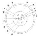
- FIG. 1is a plan view of the attachment side of a diaphragm.
- FIG. 2is a cross-sectional view of the diaphragm taken through line 2 - 2 of FIG. 1 .
- FIG. 3is a cross-sectional side view of the diaphragm assembled with an inflexible backing plate and a pump shaft.
- a diaphragm assemblyis contemplated to be employed with an air driven diaphragm pump 12 (partially illustrated).
- an air driven diaphragm pump 12(partially illustrated).
- the periphery of a diaphragm 10is retained while the center of the diaphragm 10 is associated with an oscillating pump shaft 14 .
- the diaphragm assemblyfaces a fluid chamber defined on the pump 12 as part of an actuator 16 (partially illustrated). This chamber alternately imposes pressure and venting to atmosphere to oscillate the diaphragm assembly.
- the pump chamberalternately intakes and exhausts pumped material motivated by the oscillating diaphragm assembly.
- the diaphragm 10includes an outer bead 18 , a piston 20 and a flexible peripheral portion 22 concave toward the air side located between the piston 20 and the outer bead 18 .
- the outer bead 18 and the peripheral portion 22are of conventional construction in the present embodiment.
- These diaphragms 10are contemplated to be up to and in excess of ten inches in diameter and, therefore, subject to substantial oscillating stresses imposed over a vast number of cycles during the life of the diaphragm 10 .
- This core 24may be of material such as aluminum or polymer resin.
- the core 24is considered inflexible in the sense that it does not contribute to the flexural operation of the diaphragm 10 and is not subject to fatigue failure over a large number of cycles experienced by the diaphragm 10 during its expected life.
- the inflexible core 24may be considered as divided into a hub 26 and a tapered circular plate 28 .
- the hub 26is generally cylindrical with a periphery, a first end 30 and a second end 31 .
- the circular plate 28extends radially outwardly from the periphery of the cylindrical hub 26 to substantially rigidify the entire piston 20 such that it does not contribute flexure in diaphragm operation.
- the circular plate 28has a plurality of holes 32 which are shown in this embodiment to be six in number equiangularly spaced concentrically about the center of the inflexible core 24 .
- a center attachment 34in the form of a threaded hole in the hub 26 receives the pump shaft 14 .
- a mounting surface 36extends radially about the concentric threaded hole 34 .
- thermoplastic coating 38is applied about the inflexible core 24 .
- This thermoplastic coatingis rigid at temperatures contemplated for diaphragm operation. As such, the coating 38 is closely retained about the inflexible core 24 and extends through the plurality of holes 32 .
- the end of the hub 26 with the center attachment 34 and the mounting surface 36is not coated by the thermoplastic coating 38 .
- a unitary diaphragm body 40is molded with the core 24 and thermoplastic coating 38 in situ.
- the body 40defines the outward appearance of the diaphragm 10 including the piston 20 and the peripheral portion 22 . Only the one end of the hub 26 is exposed through the unitary diaphragm body 40 and is flush with the surface of the body 40 .
- the body 40is of thermoplastic elastomer which has at least a thermally miscible surface with the thermoplastic coating 38 . It has been found convenient to use material having the same monomer for both the thermoplastic coating 38 and for the thermoplastic elastomer of the body 40 to enhance miscibility and chemical compatibility.
- the use of compatible thermoplastics and thermoplastic elastomers, including matching monomers, to bond elements togetheris a technique known in the art.
- the structure of the diaphragm body 40has been developed to provide a rigid piston 20 adhering to the inflexible core 24 .
- a plurality of connective tendons 42extend through the plurality of holes 32 to connect and tie the two sides of the body 40 together.
- An annular ring portion 44provides the peripheral terminus for the piston 20 .
- This portion 44is a thick body of thermoplastic elastomer to maintain piston inflexibility.
- the peripheral portion 22is attached smoothly without significant stress raisers.
- the diaphragm 10is assembled with the pump 12 and actuator 16 with the bead 18 positioned there between and compressed using a band clamp 48 .
- the pump shaft 14includes a threaded end 50 to be received within the center attachment 34 .
- the pump shaft 14further includes a shoulder 52 which receives an inflexible backing plate 54 such that the backing plate 54 is held against the mounting surface 36 of the piston 20 to further resist flexure.
- the diaphragms 10are contemplated to experience a very large number of cycles during their life.
- the piston 20is able to sustain such use.
- the configuration of the unitary diaphragm body 40provides strength at the annular ring portion 44 and through the plurality of connective tendons 42 .
- the holes 32 defining the tendons 42 during the molding processalso facilitate flow of material to fully form the diaphragm body 40 .
- thermoplastic coating 38 applied to the inflexible core 24 before being molded in situ within the unitary diaphragm body 40miscibly binds with the thermoplastic elastomer of the body 40 and provides a tight and rigid placement about the inflexible core 24 .
- the thin coating of thermoplastic material 38also contributes greatly to the integrity of the piston 20 during use.
Landscapes
- Engineering & Computer Science (AREA)
- Mechanical Engineering (AREA)
- General Engineering & Computer Science (AREA)
- Reciprocating Pumps (AREA)
Abstract
Description
Claims (13)
Priority Applications (1)
| Application Number | Priority Date | Filing Date | Title |
|---|---|---|---|
| US12/819,472US8496451B2 (en) | 2010-06-21 | 2010-06-21 | Pump diaphragm |
Applications Claiming Priority (1)
| Application Number | Priority Date | Filing Date | Title |
|---|---|---|---|
| US12/819,472US8496451B2 (en) | 2010-06-21 | 2010-06-21 | Pump diaphragm |
Publications (2)
| Publication Number | Publication Date |
|---|---|
| US20110311379A1 US20110311379A1 (en) | 2011-12-22 |
| US8496451B2true US8496451B2 (en) | 2013-07-30 |
Family
ID=45328849
Family Applications (1)
| Application Number | Title | Priority Date | Filing Date |
|---|---|---|---|
| US12/819,472Active2031-08-20US8496451B2 (en) | 2010-06-21 | 2010-06-21 | Pump diaphragm |
Country Status (1)
| Country | Link |
|---|---|
| US (1) | US8496451B2 (en) |
Cited By (3)
| Publication number | Priority date | Publication date | Assignee | Title |
|---|---|---|---|---|
| US20150056089A1 (en)* | 2013-08-26 | 2015-02-26 | Blue-White Industries, Ltd. | Sealing diaphragm and methods of manufacturing said diaphragm |
| USD782541S1 (en)* | 2015-10-06 | 2017-03-28 | Graco Minnesota Inc. | Diaphragm pump |
| US10422331B2 (en) | 2016-08-12 | 2019-09-24 | Ingersoll-Rand Company | One piece diaphragm |
Families Citing this family (13)
| Publication number | Priority date | Publication date | Assignee | Title |
|---|---|---|---|---|
| ES2715605T3 (en) | 2007-11-21 | 2019-06-05 | Smith & Nephew | Wound dressing |
| GB201015656D0 (en) | 2010-09-20 | 2010-10-27 | Smith & Nephew | Pressure control apparatus |
| US9067003B2 (en) | 2011-05-26 | 2015-06-30 | Kalypto Medical, Inc. | Method for providing negative pressure to a negative pressure wound therapy bandage |
| US9084845B2 (en) | 2011-11-02 | 2015-07-21 | Smith & Nephew Plc | Reduced pressure therapy apparatuses and methods of using same |
| AU2013237095B2 (en) | 2012-03-20 | 2017-10-05 | Smith & Nephew Plc | Controlling operation of a reduced pressure therapy system based on dynamic duty cycle threshold determination |
| US9427505B2 (en) | 2012-05-15 | 2016-08-30 | Smith & Nephew Plc | Negative pressure wound therapy apparatus |
| EP3237032B1 (en) | 2014-12-22 | 2024-08-07 | Smith & Nephew plc | Negative pressure wound therapy apparatus |
| CH712963A1 (en) | 2016-09-29 | 2018-03-29 | Daetwyler Schweiz Ag | Pump diaphragm for a diaphragm pump for conveying a fluid. |
| CN208934890U (en)* | 2018-10-27 | 2019-06-04 | 东莞市茗创优尚电子科技有限公司 | A kind of resilient membrane type pump housing |
| CN111520312A (en)* | 2020-04-03 | 2020-08-11 | 利穗科技(苏州)有限公司 | Alternating sanitary diaphragm pump and filtering device thereof |
| DE102020123324A1 (en) | 2020-09-07 | 2022-03-10 | Ulman Dichtungstechnik Gmbh | Composite membrane and method of manufacture |
| DE102020125567A1 (en) | 2020-09-30 | 2022-03-31 | Ulman Dichtungstechnik Gmbh | Composite diaphragm for diaphragm pumps |
| DE102020126241A1 (en)* | 2020-10-07 | 2022-04-07 | Alfmeier Präzision SE | DIAPHRAGM ARRANGEMENT |
Citations (21)
| Publication number | Priority date | Publication date | Assignee | Title |
|---|---|---|---|---|
| US4238992A (en) | 1978-10-30 | 1980-12-16 | Wilden Pump & Engineering Co. | Pump diaphragm |
| US4247264A (en) | 1979-04-13 | 1981-01-27 | Wilden Pump & Engineering Co. | Air driven diaphragm pump |
| US4270441A (en) | 1978-10-30 | 1981-06-02 | Wilden Pump & Engineering Co. | Pump diaphragm |
| USD275858S (en) | 1982-06-01 | 1984-10-09 | Wilden Pump & Engineering Co. | Double diaphragm pump |
| US4549467A (en) | 1983-08-03 | 1985-10-29 | Wilden Pump & Engineering Co. | Actuator valve |
| USD294947S (en) | 1984-08-06 | 1988-03-29 | Wilden Pump & Engineering Co. | Air driven diaphragm pump |
| USD294946S (en) | 1984-08-06 | 1988-03-29 | Wilden Pump & Engineering Co. | Air driven diaphragm pump |
| US5169296A (en) | 1989-03-10 | 1992-12-08 | Wilden James K | Air driven double diaphragm pump |
| US5634391A (en)* | 1996-07-09 | 1997-06-03 | Westinghouse Air Brake Co. | Inert plastic coated flexible type diaphragm for application in a sanitary type pump |
| US5687633A (en)* | 1996-07-09 | 1997-11-18 | Westinghouse Air Brake Company | Insert type member for use in a flexible type pump diaphragm |
| US5743170A (en) | 1996-03-27 | 1998-04-28 | Wilden Pump & Engineering Co. | Diaphragm mechanism for an air driven diaphragm pump |
| US5957670A (en) | 1997-08-26 | 1999-09-28 | Wilden Pump & Engineering Co. | Air driven diaphragm pump |
| US6102363A (en) | 1998-04-20 | 2000-08-15 | Wilden Pump & Engineering Co. | Actuator for reciprocating air driven devices |
| US6230609B1 (en)* | 1999-06-03 | 2001-05-15 | Norton Performance Plastics Corporation | Fluoropolymer diaphragm with integral attachment device |
| US6257845B1 (en) | 1998-07-14 | 2001-07-10 | Wilden Pump & Engineering Co. | Air driven pumps and components therefor |
| US6343539B1 (en)* | 1999-11-10 | 2002-02-05 | Benjamin R. Du | Multiple layer pump diaphragm |
| US6357723B2 (en) | 1996-05-17 | 2002-03-19 | Wilden Pump & Engineering Co. | Amplified pressure air driven diaphragm pump and pressure relief valve therefor |
| US6435845B1 (en)* | 1998-07-15 | 2002-08-20 | Wilden Pump & Engineering Co. | Air driven devices and components therefor |
| US7063516B2 (en) | 2004-05-04 | 2006-06-20 | Wilden Pump And Engineering Llc | One-way valve |
| US7125229B2 (en) | 2004-05-10 | 2006-10-24 | Wilden Pump And Engineering Llc | Reciprocating air distribution system |
| US7399168B1 (en) | 2005-12-19 | 2008-07-15 | Wilden Pump And Engineering Llc | Air driven diaphragm pump |
- 2010
- 2010-06-21USUS12/819,472patent/US8496451B2/enactiveActive
Patent Citations (21)
| Publication number | Priority date | Publication date | Assignee | Title |
|---|---|---|---|---|
| US4238992A (en) | 1978-10-30 | 1980-12-16 | Wilden Pump & Engineering Co. | Pump diaphragm |
| US4270441A (en) | 1978-10-30 | 1981-06-02 | Wilden Pump & Engineering Co. | Pump diaphragm |
| US4247264A (en) | 1979-04-13 | 1981-01-27 | Wilden Pump & Engineering Co. | Air driven diaphragm pump |
| USD275858S (en) | 1982-06-01 | 1984-10-09 | Wilden Pump & Engineering Co. | Double diaphragm pump |
| US4549467A (en) | 1983-08-03 | 1985-10-29 | Wilden Pump & Engineering Co. | Actuator valve |
| USD294947S (en) | 1984-08-06 | 1988-03-29 | Wilden Pump & Engineering Co. | Air driven diaphragm pump |
| USD294946S (en) | 1984-08-06 | 1988-03-29 | Wilden Pump & Engineering Co. | Air driven diaphragm pump |
| US5169296A (en) | 1989-03-10 | 1992-12-08 | Wilden James K | Air driven double diaphragm pump |
| US5743170A (en) | 1996-03-27 | 1998-04-28 | Wilden Pump & Engineering Co. | Diaphragm mechanism for an air driven diaphragm pump |
| US6357723B2 (en) | 1996-05-17 | 2002-03-19 | Wilden Pump & Engineering Co. | Amplified pressure air driven diaphragm pump and pressure relief valve therefor |
| US5687633A (en)* | 1996-07-09 | 1997-11-18 | Westinghouse Air Brake Company | Insert type member for use in a flexible type pump diaphragm |
| US5634391A (en)* | 1996-07-09 | 1997-06-03 | Westinghouse Air Brake Co. | Inert plastic coated flexible type diaphragm for application in a sanitary type pump |
| US5957670A (en) | 1997-08-26 | 1999-09-28 | Wilden Pump & Engineering Co. | Air driven diaphragm pump |
| US6102363A (en) | 1998-04-20 | 2000-08-15 | Wilden Pump & Engineering Co. | Actuator for reciprocating air driven devices |
| US6257845B1 (en) | 1998-07-14 | 2001-07-10 | Wilden Pump & Engineering Co. | Air driven pumps and components therefor |
| US6435845B1 (en)* | 1998-07-15 | 2002-08-20 | Wilden Pump & Engineering Co. | Air driven devices and components therefor |
| US6230609B1 (en)* | 1999-06-03 | 2001-05-15 | Norton Performance Plastics Corporation | Fluoropolymer diaphragm with integral attachment device |
| US6343539B1 (en)* | 1999-11-10 | 2002-02-05 | Benjamin R. Du | Multiple layer pump diaphragm |
| US7063516B2 (en) | 2004-05-04 | 2006-06-20 | Wilden Pump And Engineering Llc | One-way valve |
| US7125229B2 (en) | 2004-05-10 | 2006-10-24 | Wilden Pump And Engineering Llc | Reciprocating air distribution system |
| US7399168B1 (en) | 2005-12-19 | 2008-07-15 | Wilden Pump And Engineering Llc | Air driven diaphragm pump |
Non-Patent Citations (2)
| Title |
|---|
| Prior Art Wilden 2.68'' Diaphragm Mar. 12, 2009. |
| Prior Art Wilden 2.68″ Diaphragm Mar. 12, 2009. |
Cited By (5)
| Publication number | Priority date | Publication date | Assignee | Title |
|---|---|---|---|---|
| US20150056089A1 (en)* | 2013-08-26 | 2015-02-26 | Blue-White Industries, Ltd. | Sealing diaphragm and methods of manufacturing said diaphragm |
| US10330094B2 (en)* | 2013-08-26 | 2019-06-25 | Blue-White Industries, Ltd. | Sealing diaphragm and methods of manufacturing said diaphragm |
| US11261857B2 (en) | 2013-08-26 | 2022-03-01 | Blue-White Industries, Ltd. | Sealing diaphragm and methods of manufacturing said diaphragm |
| USD782541S1 (en)* | 2015-10-06 | 2017-03-28 | Graco Minnesota Inc. | Diaphragm pump |
| US10422331B2 (en) | 2016-08-12 | 2019-09-24 | Ingersoll-Rand Company | One piece diaphragm |
Also Published As
| Publication number | Publication date |
|---|---|
| US20110311379A1 (en) | 2011-12-22 |
Similar Documents
| Publication | Publication Date | Title |
|---|---|---|
| US8496451B2 (en) | Pump diaphragm | |
| EP1956242B1 (en) | Diaphragm pump | |
| US5743170A (en) | Diaphragm mechanism for an air driven diaphragm pump | |
| US20090053081A1 (en) | Pump diaphragm | |
| US8016573B2 (en) | Piezoelectric-driven diaphragm pump | |
| JP5600326B2 (en) | Bellows plunger having one or more helically extending features, pumps including such bellows plungers, and related methods | |
| WO2012147477A1 (en) | Multilayer diaphragm | |
| GB2486848A (en) | Diaphragm for a pump | |
| JP2021113557A (en) | Double diaphragm pump | |
| US20200284369A1 (en) | Check valve ball stop having gasket compression stand off | |
| US11326587B2 (en) | Fluid pump | |
| CN110234873B (en) | Diaphragm with edge seal | |
| US11754181B2 (en) | Overmolded diaphragm for use in a pump | |
| US7836814B2 (en) | Metering pump with a protected pump chamber | |
| CN201771727U (en) | Structural Improvement of Squeeze Pump Diaphragm | |
| WO2021016826A1 (en) | Separator pump | |
| CN106030109B (en) | Pressurized fluid driven diaphragm pump assembly | |
| US20040069140A1 (en) | Non-metallic pressure caps and diaphragm pump housings incorporating same | |
| JP2020153393A (en) | Membrane separating unit, diaphragm valve and method for manufacturing membrane separating unit | |
| US20240141883A1 (en) | Self-locking membrane system | |
| CN209856008U (en) | Pump head of diaphragm booster pump | |
| JP5371171B2 (en) | Diaphragm pump | |
| CN119321400A (en) | Steady flow diaphragm pump | |
| CN119435355A (en) | Diaphragm assembly and diaphragm pump | |
| CN119860469A (en) | Diaphragm type vibration reduction connecting pipe with piston type self-balancing structure and design method thereof |
Legal Events
| Date | Code | Title | Description |
|---|---|---|---|
| AS | Assignment | Owner name:WILDEN PUMP AND ENGINEERING LLC, CALIFORNIA Free format text:ASSIGNMENT OF ASSIGNORS INTEREST;ASSIGNORS:HALE, NATHAN EARL;MCCALL, DAVID BRIAN;WITTKOFF, WALLACE CHRISTIAN;AND OTHERS;SIGNING DATES FROM 20100609 TO 20100617;REEL/FRAME:024566/0340 | |
| STCF | Information on status: patent grant | Free format text:PATENTED CASE | |
| FPAY | Fee payment | Year of fee payment:4 | |
| MAFP | Maintenance fee payment | Free format text:PAYMENT OF MAINTENANCE FEE, 8TH YEAR, LARGE ENTITY (ORIGINAL EVENT CODE: M1552); ENTITY STATUS OF PATENT OWNER: LARGE ENTITY Year of fee payment:8 | |
| AS | Assignment | Owner name:PSG WORLDWIDE, INC., CALIFORNIA Free format text:CHANGE OF NAME;ASSIGNOR:WILDEN PUMP AND ENGINEERING LLC;REEL/FRAME:055899/0008 Effective date:20190501 | |
| AS | Assignment | Owner name:PSG CALIFORNIA LLC, CALIFORNIA Free format text:CORRECTIVE ASSIGNMENT TO CORRECT THE ASSIGNEE NAME PREVIOUSLY RECORDED ON REEL 055899 FRAME 0008. ASSIGNOR(S) HEREBY CONFIRMS THE CHANGE OF NAME;ASSIGNOR:WILDEN PUMP AND ENGINEERING, LLC;REEL/FRAME:055966/0822 Effective date:20190501 | |
| MAFP | Maintenance fee payment | Free format text:PAYMENT OF MAINTENANCE FEE, 12TH YEAR, LARGE ENTITY (ORIGINAL EVENT CODE: M1553); ENTITY STATUS OF PATENT OWNER: LARGE ENTITY Year of fee payment:12 |