US8496399B2 - Longitudinal pavement joint and apparatus for making - Google Patents
Longitudinal pavement joint and apparatus for makingDownload PDFInfo
- Publication number
- US8496399B2 US8496399B2US13/345,884US201213345884AUS8496399B2US 8496399 B2US8496399 B2US 8496399B2US 201213345884 AUS201213345884 AUS 201213345884AUS 8496399 B2US8496399 B2US 8496399B2
- Authority
- US
- United States
- Prior art keywords
- trowel
- joining surface
- joining
- degrees
- trowels
- Prior art date
- Legal status (The legal status is an assumption and is not a legal conclusion. Google has not performed a legal analysis and makes no representation as to the accuracy of the status listed.)
- Expired - Fee Related
Links
- 230000008901benefitEffects0.000description2
- 238000012986modificationMethods0.000description2
- 230000004048modificationEffects0.000description2
- 239000004831Hot glueSubstances0.000description1
- 239000011398Portland cementSubstances0.000description1
- 239000011384asphalt concreteSubstances0.000description1
- 239000004567concreteSubstances0.000description1
- 238000000034methodMethods0.000description1
- 238000007789sealingMethods0.000description1
- 238000007493shaping processMethods0.000description1
- 239000002689soilSubstances0.000description1
Images

Classifications
- E—FIXED CONSTRUCTIONS
- E01—CONSTRUCTION OF ROADS, RAILWAYS, OR BRIDGES
- E01C—CONSTRUCTION OF, OR SURFACES FOR, ROADS, SPORTS GROUNDS, OR THE LIKE; MACHINES OR AUXILIARY TOOLS FOR CONSTRUCTION OR REPAIR
- E01C11/00—Details of pavings
- E01C11/02—Arrangement or construction of joints; Methods of making joints; Packing for joints
- E01C11/04—Arrangement or construction of joints; Methods of making joints; Packing for joints for cement concrete paving
- E01C11/06—Methods of making joints
- E—FIXED CONSTRUCTIONS
- E01—CONSTRUCTION OF ROADS, RAILWAYS, OR BRIDGES
- E01C—CONSTRUCTION OF, OR SURFACES FOR, ROADS, SPORTS GROUNDS, OR THE LIKE; MACHINES OR AUXILIARY TOOLS FOR CONSTRUCTION OR REPAIR
- E01C2301/00—Machine characteristics, parts or accessories not otherwise provided for
- E01C2301/20—Screed or paver accessories for paving joint or edge treatment
Definitions
- the present inventionrelates generally to the field of paving and more specifically to the longitudinal pavement joints occurring when roadways are paved in partial-width sections.
- pavementrefers to any material—including, without limitation, asphalt concrete, Portland cement concrete, HMA, soil, or gravel—laid down over a pre-existing roadway
- roadwayrefers to any surface on which a paving machine (paver) may be driven including, without limitation, streets, roads, highways, driveways, bicycle paths, jogging paths, runways, and unpaved road beds
- pavingrefers to the process of laying down pavement.
- pavement-shaping devicesare used to produce a desired shape at an edge of a paved roadway.
- the desired shapeprovides a ramp to allow vehicles to more easily and more safely regain the paved roadway after inadvertently driving off the edge.
- roadwaysare paved in partial-width sections, creating a temporary pavement edge which is eventually incorporated into a longitudinal pavement joint between adjacent partial-width sections of pavement.
- the desired shapeoften provides additional features to promote effective sealing of the longitudinal pavement joint.
- a longitudinal pavement joint for joining pavement lanescomprising: one or more joining surfaces having respective slope angles between about 0 and about 45 degrees; and optionally, one or more wall surfaces having respective slope angles between about 45 and about 90 degrees, the joining surfaces and the wall surfaces being disposed adjacent one another, and one or more of the joining surfaces comprising a respective joining surface feature.
- an apparatus for making a longitudinal pavement jointcomprises: one or more joining surface trowels having respective slope angles between about 0 and about 45 degrees; and optionally, one or more wall surface trowels having respective slope angles between about 45 and about 90 degrees, the joining surface trowels and the wall surface trowels being disposed and mechanically coupled adjacent one another, and one or more of the joining surface trowels comprising a respective joining surface feature trowel.
- FIG. 1illustrates a perspective drawing in accordance with one aspect and one embodiment of the present invention.
- FIG. 2illustrates a perspective drawing in accordance with an alternative embodiment of the embodiment of FIG. 1 .
- FIG. 3illustrates a perspective drawing in accordance with another aspect and another embodiment of the present invention.
- FIG. 4illustrates a perspective drawing in accordance with an alternative embodiment of the embodiment of FIG. 3 .
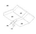
- FIG. 1illustrates a perspective drawing showing longitudinal pavement joint 100 for joining pavement lanes.
- Longitudinal pavement joint 100comprises one or more joining surfaces 110 having respective slope angles between about 0 and about 45 degrees, and optionally, one or more wall surfaces 150 having respective slope angles between about 45 and about 90 degrees where all slope angles are reckoned from the horizontal.
- Joining surfaces 110 and wall surfaces 150are disposed adjacent one another.
- joining surfaces 110comprises a respective joining surface feature 120 .
- Joining surface feature 120improves the effectiveness of longitudinal pavement joint 100 by increasing the joint surface area.
- longitudinal pavement joint 100comprises a first wall surface 160 having a slope angle between about 45 and about 90 degrees, a first joining surface 170 having a slope angle between about 0 and about 45 degrees and being disposed adjacent first wall surface 160 , a second joining surface 180 having a slope angle between about 0 and about 45 degrees and being disposed adjacent first joining surface 170 , and a second wall surface 190 having a slope angle between about 45 and about 90 degrees and being disposed adjacent second joining surface 180 .
- Second joining surface 180comprises joining surface feature 120 shown as a pavement groove 130 with a triangular cross section.
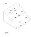
- FIG. 2illustrates a perspective drawing showing longitudinal pavement joint 100 with no wall surfaces 150 and only a single joining surface 110 .
- Joining surface 110comprises joining surface feature 120 shown as a pavement bump 140 with a semicircular cross section.
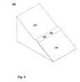
- FIG. 3illustrates a perspective drawing of an apparatus 200 for making a longitudinal pavement joint 100 .
- Apparatus 200comprises one or more joining surface trowels 210 having respective slope angles between about 0 and about 45 degrees, and optionally, one or more wall surface trowels 230 having respective slope angles between about 45 and about 90 degrees where all slope angles are reckoned from the horizontal.
- Joining surface trowels 210 and wall surface trowels 230are disposed and mechanically coupled adjacent one another.
- One or more of joining surface trowels 210comprises a respective joining surface feature trowel 220 .
- the trowelsare configured for producing corresponding joining surfaces 110 and wall surfaces 150 as shown in FIG. 1 .
- apparatus 200comprises a first wall surface trowel 260 having a slope angle between about 45 and about 90 degrees, a first joining surface trowel 270 having a slope angle between about 0 and about 45 degrees and being disposed and mechanically coupled adjacent first wall surface trowel 260 , a second joining surface trowel 280 having a slope angle between about 0 and about 45 degrees and being disposed and mechanically coupled adjacent first joining surface trowel 270 , and a second wall surface trowel 290 having a slope angle between about 45 and about 90 degrees and being disposed and mechanically coupled adjacent second joining surface trowel 280 .
- Second joining surface trowel 280comprises a joining surface feature trowel 220 shown as an apparatus bump 250 with a triangular cross section.
- apparatus 200further comprises one or more funneling trowels 300 disposed and mechanically coupled adjacent joining surface trowels 210 and wall surface trowels 230 .
- Funneling trowels 300guide unshaped pavement toward joining surface trowels 210 and wall surface trowels 230 .
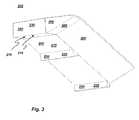
- FIG. 4illustrates a perspective drawing showing apparatus 200 having no wall surface trowels 230 and only a single joining surface trowel 210 .
- Joining surface trowel 210comprises joining surface feature trowel 220 shown as an apparatus groove 240 with a semicircular cross section.
Landscapes
- Engineering & Computer Science (AREA)
- Architecture (AREA)
- Civil Engineering (AREA)
- Structural Engineering (AREA)
- Road Paving Structures (AREA)
Abstract
Description
Claims (4)
Priority Applications (1)
| Application Number | Priority Date | Filing Date | Title |
|---|---|---|---|
| US13/345,884US8496399B2 (en) | 2011-01-20 | 2012-01-09 | Longitudinal pavement joint and apparatus for making |
Applications Claiming Priority (2)
| Application Number | Priority Date | Filing Date | Title |
|---|---|---|---|
| US201161434743P | 2011-01-20 | 2011-01-20 | |
| US13/345,884US8496399B2 (en) | 2011-01-20 | 2012-01-09 | Longitudinal pavement joint and apparatus for making |
Publications (2)
| Publication Number | Publication Date |
|---|---|
| US20120189387A1 US20120189387A1 (en) | 2012-07-26 |
| US8496399B2true US8496399B2 (en) | 2013-07-30 |
Family
ID=46544272
Family Applications (1)
| Application Number | Title | Priority Date | Filing Date |
|---|---|---|---|
| US13/345,884Expired - Fee RelatedUS8496399B2 (en) | 2011-01-20 | 2012-01-09 | Longitudinal pavement joint and apparatus for making |
Country Status (1)
| Country | Link |
|---|---|
| US (1) | US8496399B2 (en) |
Cited By (1)
| Publication number | Priority date | Publication date | Assignee | Title |
|---|---|---|---|---|
| US9290893B2 (en) | 2013-04-08 | 2016-03-22 | Advant-Edge Paving Equipment, LLC | Roadway paving system |
Citations (21)
| Publication number | Priority date | Publication date | Assignee | Title |
|---|---|---|---|---|
| US78381A (en)* | 1868-05-26 | Alexander leverty | ||
| US166666A (en)* | 1875-08-10 | Improvement in cornice-tools | ||
| US1570177A (en)* | 1923-01-29 | 1926-01-19 | James B Pointer | Sanding block |
| US3915583A (en)* | 1973-04-02 | 1975-10-28 | Carl Aparicio | Paving machine slip form |
| US4181449A (en) | 1978-08-02 | 1980-01-01 | Lenker Earl A | Paving joints |
| US5819485A (en)* | 1997-09-15 | 1998-10-13 | Exterior Specialty Systems, Inc. | Interior molding system |
| US6106192A (en)* | 1998-04-17 | 2000-08-22 | Blaw-Knox Construction Equipment Corp. | Flow modifying device for paving screeds with extendible sections |
| US6139223A (en)* | 1998-11-20 | 2000-10-31 | Snyder; Robert Wayne | Trench filler |
| US6238136B1 (en) | 1999-03-19 | 2001-05-29 | Transtech Systems, Inc. | Paving machine and pavement edger therefor |
| US6238134B1 (en) | 1999-03-19 | 2001-05-29 | Transtech Systems, Inc. | Pavement ramp and ramp making process |
| US6270284B1 (en) | 1999-03-19 | 2001-08-07 | Transtech Systems, Inc. | Pavement joint and joint making process |
| US6283672B1 (en) | 1999-07-16 | 2001-09-04 | Transtech Systems, Inc. | Pavement edger and joint maker |
| US20030192142A1 (en)* | 2002-04-10 | 2003-10-16 | Nadine Veith | Hand-held device or tool for forming plastic masses, especially for producing and/or forming raised profiles |
| US6709195B2 (en)* | 2000-09-29 | 2004-03-23 | N. Piccoli Construction | Moveable tailpiece for attachment to a curb forming machine for producing low curb profiles |
| US6729088B2 (en)* | 2002-02-05 | 2004-05-04 | Shannon L. Corr | Positioning jig for installing molding |
| US6923594B2 (en) | 2003-04-29 | 2005-08-02 | Transtech Systems, Inc. | Pavement ramp edge making |
| US6988850B2 (en) | 2003-04-29 | 2006-01-24 | Transtech Systems, Inc. | Pavement ramp edge making |
| US7172364B1 (en)* | 2006-03-17 | 2007-02-06 | Nicholson Concrete | Dropped curb finisher |
| US7246402B2 (en)* | 2005-02-04 | 2007-07-24 | Wal-Tech Industries Ltd. | Variable angle corner tool |
| US7610648B2 (en)* | 2005-01-12 | 2009-11-03 | Bon Tool Company | Stainless steel tool and method of forming |
| US7725982B2 (en)* | 2007-10-05 | 2010-06-01 | Hoch Stephen C | Hinged corner trowel |
- 2012
- 2012-01-09USUS13/345,884patent/US8496399B2/ennot_activeExpired - Fee Related
Patent Citations (21)
| Publication number | Priority date | Publication date | Assignee | Title |
|---|---|---|---|---|
| US78381A (en)* | 1868-05-26 | Alexander leverty | ||
| US166666A (en)* | 1875-08-10 | Improvement in cornice-tools | ||
| US1570177A (en)* | 1923-01-29 | 1926-01-19 | James B Pointer | Sanding block |
| US3915583A (en)* | 1973-04-02 | 1975-10-28 | Carl Aparicio | Paving machine slip form |
| US4181449A (en) | 1978-08-02 | 1980-01-01 | Lenker Earl A | Paving joints |
| US5819485A (en)* | 1997-09-15 | 1998-10-13 | Exterior Specialty Systems, Inc. | Interior molding system |
| US6106192A (en)* | 1998-04-17 | 2000-08-22 | Blaw-Knox Construction Equipment Corp. | Flow modifying device for paving screeds with extendible sections |
| US6139223A (en)* | 1998-11-20 | 2000-10-31 | Snyder; Robert Wayne | Trench filler |
| US6270284B1 (en) | 1999-03-19 | 2001-08-07 | Transtech Systems, Inc. | Pavement joint and joint making process |
| US6238134B1 (en) | 1999-03-19 | 2001-05-29 | Transtech Systems, Inc. | Pavement ramp and ramp making process |
| US6238136B1 (en) | 1999-03-19 | 2001-05-29 | Transtech Systems, Inc. | Paving machine and pavement edger therefor |
| US6283672B1 (en) | 1999-07-16 | 2001-09-04 | Transtech Systems, Inc. | Pavement edger and joint maker |
| US6709195B2 (en)* | 2000-09-29 | 2004-03-23 | N. Piccoli Construction | Moveable tailpiece for attachment to a curb forming machine for producing low curb profiles |
| US6729088B2 (en)* | 2002-02-05 | 2004-05-04 | Shannon L. Corr | Positioning jig for installing molding |
| US20030192142A1 (en)* | 2002-04-10 | 2003-10-16 | Nadine Veith | Hand-held device or tool for forming plastic masses, especially for producing and/or forming raised profiles |
| US6923594B2 (en) | 2003-04-29 | 2005-08-02 | Transtech Systems, Inc. | Pavement ramp edge making |
| US6988850B2 (en) | 2003-04-29 | 2006-01-24 | Transtech Systems, Inc. | Pavement ramp edge making |
| US7610648B2 (en)* | 2005-01-12 | 2009-11-03 | Bon Tool Company | Stainless steel tool and method of forming |
| US7246402B2 (en)* | 2005-02-04 | 2007-07-24 | Wal-Tech Industries Ltd. | Variable angle corner tool |
| US7172364B1 (en)* | 2006-03-17 | 2007-02-06 | Nicholson Concrete | Dropped curb finisher |
| US7725982B2 (en)* | 2007-10-05 | 2010-06-01 | Hoch Stephen C | Hinged corner trowel |
Cited By (1)
| Publication number | Priority date | Publication date | Assignee | Title |
|---|---|---|---|---|
| US9290893B2 (en) | 2013-04-08 | 2016-03-22 | Advant-Edge Paving Equipment, LLC | Roadway paving system |
Also Published As
| Publication number | Publication date |
|---|---|
| US20120189387A1 (en) | 2012-07-26 |
Similar Documents
| Publication | Publication Date | Title |
|---|---|---|
| US20220042260A1 (en) | One piece water permeable paver | |
| US20120183350A1 (en) | Apparatus for Shaping Pavement | |
| PL2245117T3 (en) | Bituminous compositions | |
| AU608240B2 (en) | Frame for laying wooden bricks | |
| US6719486B2 (en) | Apparatus for screeding | |
| US8496399B2 (en) | Longitudinal pavement joint and apparatus for making | |
| US510259A (en) | Pavement | |
| KR100889252B1 (en) | Block with load distribution | |
| JP6474626B2 (en) | Curb structure and its construction method | |
| RU2648122C1 (en) | Method of road covering on pads arrangement | |
| Fort | Massive impact | |
| EP4317587A4 (en) | ASPHALT FINISHER AND ROAD SURFACE PAVING SYSTEM | |
| CN202744918U (en) | Road kerb | |
| RU2540996C1 (en) | Method to establish transport road (versions) | |
| EA026780B1 (en) | Structure for build-up of a road kerb | |
| CN202744919U (en) | Road kerb | |
| JP2014194118A (en) | Construction method for pavement body, and construction method for pavement structure | |
| KR200190054Y1 (en) | Paving road using used tire block | |
| RU2663885C1 (en) | Method of road covering of modular type | |
| US779294A (en) | Roadway. | |
| LV14348A (en) | Upper part of multi-course asphalt pavement construction | |
| RU80860U1 (en) | ROAD ROAD CONSTRUCTION | |
| RU2515789C2 (en) | Motor road coated by boards and method for its operation, board for road coverage | |
| RU146609U1 (en) | DESIGN OF THE REGIONAL ROAD ROAD P 0159 G. NIZHNY NOVGOROD - G. KIROV ON THE SITE G. NIZHNY NOVGOROD - P. Neklyudovo | |
| Varamini et al. | Design and Field Performance of Cold-Constructed Asphalt Pavements (CCAP) with Gelled Asphalts |
Legal Events
| Date | Code | Title | Description |
|---|---|---|---|
| REMI | Maintenance fee reminder mailed | ||
| LAPS | Lapse for failure to pay maintenance fees | Free format text:PATENT EXPIRED FOR FAILURE TO PAY MAINTENANCE FEES (ORIGINAL EVENT CODE: EXP.) | |
| PRDP | Patent reinstated due to the acceptance of a late maintenance fee | Effective date:20170912 | |
| FEPP | Fee payment procedure | Free format text:SURCHARGE, PETITION TO ACCEPT PYMT AFTER EXP, UNINTENTIONAL. (ORIGINAL EVENT CODE: M2558); ENTITY STATUS OF PATENT OWNER: SMALL ENTITY Free format text:PETITION RELATED TO MAINTENANCE FEES GRANTED (ORIGINAL EVENT CODE: PMFG) Free format text:PETITION RELATED TO MAINTENANCE FEES FILED (ORIGINAL EVENT CODE: PMFP) | |
| MAFP | Maintenance fee payment | Free format text:PAYMENT OF MAINTENANCE FEE, 4TH YR, SMALL ENTITY (ORIGINAL EVENT CODE: M2551) Year of fee payment:4 | |
| STCF | Information on status: patent grant | Free format text:PATENTED CASE | |
| FP | Lapsed due to failure to pay maintenance fee | Effective date:20170730 | |
| FEPP | Fee payment procedure | Free format text:MAINTENANCE FEE REMINDER MAILED (ORIGINAL EVENT CODE: REM.); ENTITY STATUS OF PATENT OWNER: SMALL ENTITY | |
| LAPS | Lapse for failure to pay maintenance fees | Free format text:PATENT EXPIRED FOR FAILURE TO PAY MAINTENANCE FEES (ORIGINAL EVENT CODE: EXP.); ENTITY STATUS OF PATENT OWNER: SMALL ENTITY | |
| STCH | Information on status: patent discontinuation | Free format text:PATENT EXPIRED DUE TO NONPAYMENT OF MAINTENANCE FEES UNDER 37 CFR 1.362 | |
| FP | Lapsed due to failure to pay maintenance fee | Effective date:20210730 |