US8496318B2 - Liquid drop ejection using dual feed ejector - Google Patents
Liquid drop ejection using dual feed ejectorDownload PDFInfo
- Publication number
- US8496318B2 US8496318B2US12/917,899US91789910AUS8496318B2US 8496318 B2US8496318 B2US 8496318B2US 91789910 AUS91789910 AUS 91789910AUS 8496318 B2US8496318 B2US 8496318B2
- Authority
- US
- United States
- Prior art keywords
- liquid
- chamber
- segment
- drop
- chambers
- Prior art date
- Legal status (The legal status is an assumption and is not a legal conclusion. Google has not performed a legal analysis and makes no representation as to the accuracy of the status listed.)
- Expired - Fee Related, expires
Links
Images


Classifications
- B—PERFORMING OPERATIONS; TRANSPORTING
- B41—PRINTING; LINING MACHINES; TYPEWRITERS; STAMPS
- B41J—TYPEWRITERS; SELECTIVE PRINTING MECHANISMS, i.e. MECHANISMS PRINTING OTHERWISE THAN FROM A FORME; CORRECTION OF TYPOGRAPHICAL ERRORS
- B41J2/00—Typewriters or selective printing mechanisms characterised by the printing or marking process for which they are designed
- B41J2/005—Typewriters or selective printing mechanisms characterised by the printing or marking process for which they are designed characterised by bringing liquid or particles selectively into contact with a printing material
- B41J2/01—Ink jet
- B41J2/135—Nozzles
- B41J2/14—Structure thereof only for on-demand ink jet heads
- B41J2/14016—Structure of bubble jet print heads
- B41J2/14032—Structure of the pressure chamber
- B41J2/1404—Geometrical characteristics
- B—PERFORMING OPERATIONS; TRANSPORTING
- B41—PRINTING; LINING MACHINES; TYPEWRITERS; STAMPS
- B41J—TYPEWRITERS; SELECTIVE PRINTING MECHANISMS, i.e. MECHANISMS PRINTING OTHERWISE THAN FROM A FORME; CORRECTION OF TYPOGRAPHICAL ERRORS
- B41J2/00—Typewriters or selective printing mechanisms characterised by the printing or marking process for which they are designed
- B41J2/005—Typewriters or selective printing mechanisms characterised by the printing or marking process for which they are designed characterised by bringing liquid or particles selectively into contact with a printing material
- B41J2/01—Ink jet
- B41J2/135—Nozzles
- B41J2/14—Structure thereof only for on-demand ink jet heads
- B—PERFORMING OPERATIONS; TRANSPORTING
- B41—PRINTING; LINING MACHINES; TYPEWRITERS; STAMPS
- B41J—TYPEWRITERS; SELECTIVE PRINTING MECHANISMS, i.e. MECHANISMS PRINTING OTHERWISE THAN FROM A FORME; CORRECTION OF TYPOGRAPHICAL ERRORS
- B41J2/00—Typewriters or selective printing mechanisms characterised by the printing or marking process for which they are designed
- B41J2/005—Typewriters or selective printing mechanisms characterised by the printing or marking process for which they are designed characterised by bringing liquid or particles selectively into contact with a printing material
- B41J2/01—Ink jet
- B41J2/015—Ink jet characterised by the jet generation process
- B41J2/04—Ink jet characterised by the jet generation process generating single droplets or particles on demand
- B41J2/045—Ink jet characterised by the jet generation process generating single droplets or particles on demand by pressure, e.g. electromechanical transducers
- B41J2/055—Devices for absorbing or preventing back-pressure
- B—PERFORMING OPERATIONS; TRANSPORTING
- B41—PRINTING; LINING MACHINES; TYPEWRITERS; STAMPS
- B41J—TYPEWRITERS; SELECTIVE PRINTING MECHANISMS, i.e. MECHANISMS PRINTING OTHERWISE THAN FROM A FORME; CORRECTION OF TYPOGRAPHICAL ERRORS
- B41J2/00—Typewriters or selective printing mechanisms characterised by the printing or marking process for which they are designed
- B41J2/005—Typewriters or selective printing mechanisms characterised by the printing or marking process for which they are designed characterised by bringing liquid or particles selectively into contact with a printing material
- B41J2/01—Ink jet
- B41J2/135—Nozzles
- B41J2/14—Structure thereof only for on-demand ink jet heads
- B41J2/14016—Structure of bubble jet print heads
- B41J2/14072—Electrical connections, e.g. details on electrodes, connecting the chip to the outside...
- B—PERFORMING OPERATIONS; TRANSPORTING
- B41—PRINTING; LINING MACHINES; TYPEWRITERS; STAMPS
- B41J—TYPEWRITERS; SELECTIVE PRINTING MECHANISMS, i.e. MECHANISMS PRINTING OTHERWISE THAN FROM A FORME; CORRECTION OF TYPOGRAPHICAL ERRORS
- B41J2/00—Typewriters or selective printing mechanisms characterised by the printing or marking process for which they are designed
- B41J2/005—Typewriters or selective printing mechanisms characterised by the printing or marking process for which they are designed characterised by bringing liquid or particles selectively into contact with a printing material
- B41J2/01—Ink jet
- B41J2/135—Nozzles
- B41J2/14—Structure thereof only for on-demand ink jet heads
- B41J2/14016—Structure of bubble jet print heads
- B41J2/14145—Structure of the manifold
- B—PERFORMING OPERATIONS; TRANSPORTING
- B41—PRINTING; LINING MACHINES; TYPEWRITERS; STAMPS
- B41J—TYPEWRITERS; SELECTIVE PRINTING MECHANISMS, i.e. MECHANISMS PRINTING OTHERWISE THAN FROM A FORME; CORRECTION OF TYPOGRAPHICAL ERRORS
- B41J2/00—Typewriters or selective printing mechanisms characterised by the printing or marking process for which they are designed
- B41J2/005—Typewriters or selective printing mechanisms characterised by the printing or marking process for which they are designed characterised by bringing liquid or particles selectively into contact with a printing material
- B41J2/01—Ink jet
- B41J2/17—Ink jet characterised by ink handling
- B41J2/175—Ink supply systems ; Circuit parts therefor
- H—ELECTRICITY
- H04—ELECTRIC COMMUNICATION TECHNIQUE
- H04L—TRANSMISSION OF DIGITAL INFORMATION, e.g. TELEGRAPHIC COMMUNICATION
- H04L43/00—Arrangements for monitoring or testing data switching networks
- H04L43/08—Monitoring or testing based on specific metrics, e.g. QoS, energy consumption or environmental parameters
- H04L43/0852—Delays
- H04L43/0864—Round trip delays
- H—ELECTRICITY
- H04—ELECTRIC COMMUNICATION TECHNIQUE
- H04L—TRANSMISSION OF DIGITAL INFORMATION, e.g. TELEGRAPHIC COMMUNICATION
- H04L43/00—Arrangements for monitoring or testing data switching networks
- H04L43/12—Network monitoring probes
- B—PERFORMING OPERATIONS; TRANSPORTING
- B41—PRINTING; LINING MACHINES; TYPEWRITERS; STAMPS
- B41J—TYPEWRITERS; SELECTIVE PRINTING MECHANISMS, i.e. MECHANISMS PRINTING OTHERWISE THAN FROM A FORME; CORRECTION OF TYPOGRAPHICAL ERRORS
- B41J2/00—Typewriters or selective printing mechanisms characterised by the printing or marking process for which they are designed
- B41J2/005—Typewriters or selective printing mechanisms characterised by the printing or marking process for which they are designed characterised by bringing liquid or particles selectively into contact with a printing material
- B41J2/01—Ink jet
- B41J2/135—Nozzles
- B41J2/14—Structure thereof only for on-demand ink jet heads
- B41J2002/14387—Front shooter
- B—PERFORMING OPERATIONS; TRANSPORTING
- B41—PRINTING; LINING MACHINES; TYPEWRITERS; STAMPS
- B41J—TYPEWRITERS; SELECTIVE PRINTING MECHANISMS, i.e. MECHANISMS PRINTING OTHERWISE THAN FROM A FORME; CORRECTION OF TYPOGRAPHICAL ERRORS
- B41J2/00—Typewriters or selective printing mechanisms characterised by the printing or marking process for which they are designed
- B41J2/005—Typewriters or selective printing mechanisms characterised by the printing or marking process for which they are designed characterised by bringing liquid or particles selectively into contact with a printing material
- B41J2/01—Ink jet
- B41J2/135—Nozzles
- B41J2/14—Structure thereof only for on-demand ink jet heads
- B41J2002/14403—Structure thereof only for on-demand ink jet heads including a filter
- B—PERFORMING OPERATIONS; TRANSPORTING
- B41—PRINTING; LINING MACHINES; TYPEWRITERS; STAMPS
- B41J—TYPEWRITERS; SELECTIVE PRINTING MECHANISMS, i.e. MECHANISMS PRINTING OTHERWISE THAN FROM A FORME; CORRECTION OF TYPOGRAPHICAL ERRORS
- B41J2/00—Typewriters or selective printing mechanisms characterised by the printing or marking process for which they are designed
- B41J2/005—Typewriters or selective printing mechanisms characterised by the printing or marking process for which they are designed characterised by bringing liquid or particles selectively into contact with a printing material
- B41J2/01—Ink jet
- B41J2/135—Nozzles
- B41J2/14—Structure thereof only for on-demand ink jet heads
- B41J2002/14467—Multiple feed channels per ink chamber
- B—PERFORMING OPERATIONS; TRANSPORTING
- B41—PRINTING; LINING MACHINES; TYPEWRITERS; STAMPS
- B41J—TYPEWRITERS; SELECTIVE PRINTING MECHANISMS, i.e. MECHANISMS PRINTING OTHERWISE THAN FROM A FORME; CORRECTION OF TYPOGRAPHICAL ERRORS
- B41J2/00—Typewriters or selective printing mechanisms characterised by the printing or marking process for which they are designed
- B41J2/005—Typewriters or selective printing mechanisms characterised by the printing or marking process for which they are designed characterised by bringing liquid or particles selectively into contact with a printing material
- B41J2/01—Ink jet
- B41J2/135—Nozzles
- B41J2/14—Structure thereof only for on-demand ink jet heads
- B41J2002/14475—Structure thereof only for on-demand ink jet heads characterised by nozzle shapes or number of orifices per chamber
- B—PERFORMING OPERATIONS; TRANSPORTING
- B41—PRINTING; LINING MACHINES; TYPEWRITERS; STAMPS
- B41J—TYPEWRITERS; SELECTIVE PRINTING MECHANISMS, i.e. MECHANISMS PRINTING OTHERWISE THAN FROM A FORME; CORRECTION OF TYPOGRAPHICAL ERRORS
- B41J2202/00—Embodiments of or processes related to ink-jet or thermal heads
- B41J2202/01—Embodiments of or processes related to ink-jet heads
- B41J2202/18—Electrical connection established using vias
- Y—GENERAL TAGGING OF NEW TECHNOLOGICAL DEVELOPMENTS; GENERAL TAGGING OF CROSS-SECTIONAL TECHNOLOGIES SPANNING OVER SEVERAL SECTIONS OF THE IPC; TECHNICAL SUBJECTS COVERED BY FORMER USPC CROSS-REFERENCE ART COLLECTIONS [XRACs] AND DIGESTS
- Y04—INFORMATION OR COMMUNICATION TECHNOLOGIES HAVING AN IMPACT ON OTHER TECHNOLOGY AREAS
- Y04S—SYSTEMS INTEGRATING TECHNOLOGIES RELATED TO POWER NETWORK OPERATION, COMMUNICATION OR INFORMATION TECHNOLOGIES FOR IMPROVING THE ELECTRICAL POWER GENERATION, TRANSMISSION, DISTRIBUTION, MANAGEMENT OR USAGE, i.e. SMART GRIDS
- Y04S40/00—Systems for electrical power generation, transmission, distribution or end-user application management characterised by the use of communication or information technologies, or communication or information technology specific aspects supporting them
Definitions
- This inventionrelates generally to the field of digitally controlled printing systems, and in particular to the liquid drop ejector component of these systems.
- US Patent Application Publication No. US 2004/0263578 A1discloses an inkjet printhead that includes a substrate having an ink chamber and a manifold, a nozzle plate formed on the substrate, first and second heaters, first and second conductors, and first and second ink channels.
- the nozzle plateincludes a nozzle passing through the nozzle plate and in flow communication with the ink chamber.
- the first and second heaters and conductorsare interposed between adjacent passivation layers of the nozzle plate.
- the ink channelsare interposed between the ink chamber and the manifold, for providing flow communication between the ink chamber and the manifold.
- the first and second heaters, conductors and ink channelsare symmetric with respect to the nozzle.
- a liquid ejectorincludes a structure defining a plurality of chambers with one of the plurality of chambers including a first surface and a second surface.
- the first surfaceincludes a nozzle orifice.
- a drop forming mechanismis located on the second surface of the chamber opposite the nozzle orifice.
- a first liquid feed channel and a second liquid feed channelare in fluid communication with the chamber.
- a first segment of a segmented liquid inletis in fluid communication with the first liquid feed channel and a second segment of the segmented liquid inlet is in fluid communication with the second liquid feed channel.
- the first segment of the segmented liquid inletis also in fluid communication with another one of the plurality of chambers and the second segment of the liquid inlet is also in fluid communication with another one of the plurality of chambers.
- a liquidis provided to the chamber through the first liquid feed channel and the second liquid feed channel from the segmented liquid inlet.
- a drop of the liquidis ejected through the nozzle orifice of the chamber by operating the associated drop forming mechanism.
- Liquid drop ejectioncan be accomplished by sending a signal from a data source to a controller, sending a command from the controller to an electrical pulse source in response to the signal, and sending an electrical pulse to the drop forming mechanism in response to the command.
- the electrical pulsecan be sent to the drop forming mechanism by conducting the electrical pulse along an electrical lead disposed between neighboring segments of the segmented inlet.
- the drop forming mechanismcan include a resistive heating element. When so configured, the drop forming mechanism can be operated such that a bubble is formed over the resistive heating element to eject a liquid drop.
- the chambercan be refilled after the liquid drop is ejected through the nozzle orifice of the chamber by providing liquid to the chamber through the first ink feed channel and the second ink feed channel from the segmented inlet. This can include providing liquid to the chamber from opposite sides of the chamber.
- the liquid ejectorcan include a post positioned in one or a combination of the chamber, the first ink feed channel, or the second ink feed channel.
- the postrestricts the amount and momentum of liquid flow away from the chamber after the liquid drop has been ejected through the nozzle orifice of the chamber.
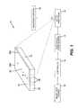
- FIG. 1is a schematic representation of a liquid ejection system incorporating the present invention
- FIGS. 2 a and 2 bare schematic top views of a liquid ejection printhead die incorporating an example embodiment of the present invention in which ends of adjacent inlet segments are aligned;
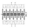
- FIG. 3is a schematic top view of a liquid ejection printhead die incorporating an example embodiment of the present invention in which ends of adjacent inlet segments overlap;
- FIG. 4is a schematic top view of a liquid ejection printhead die incorporating an example embodiment of the present invention in which ends of adjacent inlet segments are spaced apart;
- FIG. 5is a schematic cross sectional view of one liquid ejector shown through line 5 - 5 of FIG. 4 ;
- FIG. 6is a schematic top view of a liquid ejection printhead die incorporating an example embodiment of the present invention in which the posts are asymmetrically positioned within the feed channels;
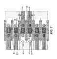
- FIG. 7is a schematic top view of a liquid ejection printhead die incorporating an example embodiment of the present invention in which the posts have different cross-sectional areas;
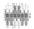
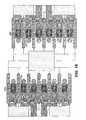
- FIG. 8is a lower magnification of a portion of a liquid ejection printhead die incorporating an example embodiment of the present invention in which additional posts are disposed between the inlet segments and the feed channels;
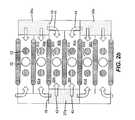
- FIG. 9is a schematic top view of a liquid ejection printhead die incorporating an example embodiment of the present invention in which none of the electrical leads extend toward a plurality of inlet segments;
- FIG. 10is a schematic top view of a liquid ejection printhead die incorporating another example embodiment of the present invention in which none of the electrical leads extend toward a plurality of inlet segments;
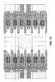
- FIG. 11is a schematic top view of a liquid ejection printhead die incorporating an example embodiment of the present invention in which power circuitry and logic circuitry are integrated on the printhead die;
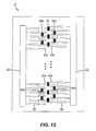
- FIG. 12is a schematic top view of a liquid ejection printhead die incorporating another example embodiment of the present invention in which power circuitry and logic circuitry are integrated on the printhead die;
- FIG. 13is a schematic top view of a liquid ejection printhead die incorporating an example embodiment of the present invention including two staggered rows of liquid ejectors;
- FIG. 14is a schematic top view of a liquid ejection printhead die incorporating an example embodiment of the present invention including two aligned rows of liquid ejectors;
- FIGS. 15-17are schematic top views of liquid ejection printhead die incorporating example embodiments of the present invention in which the ratio of the number of liquid ejectors to the number of inlet segments is less than two;
- FIG. 18is a schematic top view of a liquid ejection printhead die incorporating an example embodiment of the present invention including two staggered rows of liquid ejectors where the nozzle cross-sectional area is different in the two rows.
- liquid ejection printheadAlthough the term liquid ejection printhead is used herein, it is recognized that printheads are being used today to eject many types of liquids and not just ink. For example, the ejection of various liquids including medicines, pigments, dyes, conductive and semi-conductive organics, metal particles, and other materials is possible today using a liquid ejection printhead. As such, the term printhead is not intended to be limited to just devices that eject ink.
- One aspect of the invention described hereinrelates to the configuration of the liquid ejector and, in particular, the relationship of a drop forming mechanism and its corresponding liquid feed channels.
- Particular embodimentsare described relating to thermal inkjet printheads in which the drop forming mechanism is a resistive heating element that is pulsed to nucleate a bubble in an ink-filled chamber, and eject a droplet as the bubble expands.
- Other embodimentsinclude piezoelectric printheads, as well as MEMS type printheads, e.g. those in which the drop forming mechanism is a thermal bend actuator or an electrostatic actuator.
- Preferred fabrication methodsinclude those described in copending applications U.S. Ser. No. 11/609,375, filed Dec.
- Liquid ejection system 10includes a source 12 of data (for example, image data) which provides signals that are interpreted by a controller 14 as being commands to eject liquid drops. Controller 14 outputs signals to a source 16 of electrical energy pulses which are sent to a liquid ejection printhead die 18 .
- liquid ejection printhead die 18includes a plurality of liquid ejectors 20 arranged in at least one array, for example, a substantially linear row.
- liquidfor example, ink in the form of ink drops, is deposited on a recording medium 24 .
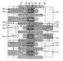
- Liquid ejection printhead die 18includes an array or plurality of liquid ejectors 20 .
- Liquid ejector 20includes a structure, for example, walls 26 extending from a substrate 28 that define a chamber 30 . Walls 26 separate liquid ejectors 20 positioned adjacent to other liquid ejectors 20 .
- Each chamber 30includes a nozzle orifice 32 in nozzle plate 31 through which liquid is ejected.
- a drop forming mechanism 34for example, a resistive heater, is also located in each chamber 30 .
- the resistive heateris positioned on the top surface of substrate 28 in the bottom of chamber 30 and opposite nozzle orifice 32 , although other configurations are permitted.
- the bottom surface of chamber 30is the top of substrate 28
- the top surface of the chamber 30is the nozzle plate 31 .
- a segmented liquid inlet or manifold 36supplies liquid to each chamber 30 through first and second liquid feed channels 38 and 40 that are in fluid communication with each chamber 30 .
- Segmented inlet 36includes a first segment 37 that is in fluid communication with first liquid feed channel 38 and a second segment 39 that is in fluid communication with second liquid feed channel 40 .
- First segments 37 and second segments 39are positioned on opposite sides of chamber 30 and nozzle orifice 32 .
- each first segment 37 of liquid inlet 36 and each second segment 39 of liquid inlet 36are positioned offset relative to each other as viewed from a plane perpendicular to a plane including nozzle orifice 32 (the view shown in FIGS. 2 a and 2 b ). Positioning first segment 37 and second segment 39 in this manner enables a segment (either first segment 37 or second segment 39 ) to provide liquid to chambers 30 that are aligned with the segment (represented by arrows 42 ) as well as provide liquid to chambers 30 that are offset from the segment (represented by arrows 44 ).
- a segmenteither first segment 37 or second segment 39
- each of first segment 37 and second segment 39supply liquid to two chambers 30 that are aligned with or located across from each segment. Additionally, each of first segment 37 and second segment 39 supply liquid to chambers 30 on either side of each segment that are offset from or located adjacent to each segment.
- FIG. 2 bThe flow patterns of FIG. 2 a are further clarified in FIG. 2 b , where some structural elements are omitted for simplification.
- Individual chambers 30 a , 30 b , 30 c and 30 dare designated, as are first segment 37 a and second segments 39 a and 39 b of liquid inlet 36 .
- a liquid feed channel feeding a particular chamberwe will refer to a liquid feed channel feeding a particular chamber. It should be understood that this channel primarily feeds the specified chamber (typically a nearby neighbor channel). However, the channel also feeds other nearby channels to a lesser extent, depending on flow requirements due to jet firing patterns.
- First liquid feed channel 38 afeeds chamber 30 a from second segment 39 a of liquid inlet 36 .
- second liquid feed channel 40 aalso feeds chamber 30 a from first segment 37 a , which is offset from and adjacent to chamber 30 a .
- Both chambers 30 b and 30 care fed by first liquid feed channels 38 b and 38 c respectively from first segment 37 a of liquid inlet 36 .
- Chamber 30 bis also fed by second liquid feed channel 40 b from second segment 39 a
- chamber 30 cis also fed by second liquid feed channel 40 c from second segment 39 b .
- Chamber 30 dis fed by first liquid feed channel 38 d from second segment 39 b , and is also fed by second liquid feed channel 40 d from first segment 37 a .
- Each chamberis fed by a first liquid feed channel 38 from a segment of liquid inlet 36 that is directly in line with the chamber, and also by a second liquid feed channel 40 from a segment of liquid feed inlet 36 that is offset somewhat from the chamber
- segments 37 and 39 of liquid inlet 36are each approximately as wide as two adjacent chambers, and the spacing between adjacent segments 39 a and 39 b is also approximately as wide as two adjacent chambers.
- two chambersare fed by first liquid feed channels 38 from segments of liquid inlet 36 that are directly in line with the chambers, and the second feed channels 40 for these two chambers are from second segments that are offset somewhat from the chamber.
- FIG. 3shows the case of more than two chambers (i.e. 3, 4, or more chambers) being fed by first liquid feed channels 38 from segments of liquid inlet 36 that are directly in line with the chambers, and also by second liquid feed channels 40 from segments of liquid inlet 36 that are somewhat offset from the chambers.
- Each of first segment 37 of the liquid inlet 36includes ends 46 that are adjacent to ends 48 of each second segment 39 of liquid inlet 38 .
- an end 46 of first segment 37is aligned with an end 48 of second segment 39 represented by dashed line 50 .
- ends 46 and 48can overlap each other as is shown in FIG. 3 .
- ends 46 and 48can be positioned spaced apart from each other as is shown in FIG. 4 .
- One or more posts 52can be disposed in chamber 30 , liquid feed channel 38 , liquid feed channel 40 , or combinations thereof. As discussed in more detail below, posts 52 can be symmetrically or asymmetrically disposed about the nozzle orifice 32 and/or within one or both of liquid feed channels 38 , 40 . Posts 52 can have the same cross sectional area or different cross sectional areas when compared to each other. Posts 52 can also have same shapes or different shapes when compared to each other.
- Liquid ejector 20includes chamber 30 connected in fluid communication with first liquid feed channel 38 which is connected in fluid communication to one of a plurality of first segments 37 of segmented liquid inlet or manifold 36 .
- Chamber 30is also connected in fluid communication with second liquid feed channel 40 which is connected in fluid communication to one of a plurality of second segments 39 of segmented liquid inlet or manifold 36 .
- first segment 37 of liquid inlet 36is aligned with chamber 30 and supplies liquid directly to chamber 30 .
- Second segment 39 of liquid inlet 36is offset relative to chamber 30 and supplies liquid indirectly to chamber 30 (represented by “X” 54 ).
- Drop forming mechanism 34for example, a resistive heater, is located in chamber 30 and is operable to eject liquid through nozzle orifice 32 .
- Posts 52are also present in chamber 30 and/or one or both of first and second liquid feed channels 38 and 40 .
- inkenters the printhead die through segmented liquid inlet 36 and passes through first and second liquid feed channels 38 and 40 from opposite directions to enter the fluid chamber 30 .
- the chamberis filled with ink through a single liquid feed channel from only one direction.
- resistive heating element 34When the chamber is filled with ink, the resistive heating element 34 , which is positioned below the nozzle orifice 32 , is in thermal contact with the pool of ink in the chamber. Resistive heating element 34 is shown in a particular configuration including two parallel legs 33 of resistive material, joined at one end by a conductive shorting bar 35 . Electrical leads 56 are connected to each leg 33 at the opposite end from the shorting bar 35 . However, other resistive heating element configurations are possible.
- source 16When data source 12 provides a signal that is interpreted by controller 14 as a command for a drop of ink to be ejected from a particular chamber 30 at a particular time, source 16 provides an electrical pulse to heater 34 through electrical leads 56 .
- the pulse voltageis chosen such that a bubble is nucleated in the superheated ink over the heater.
- the size of the droplet(i.e. its volume or mass, and related to the size of the dot produced on recording medium 24 ) is determined primarily by size of the heater 34 , size of the nozzle 32 , and geometry of the chamber 30 , and to a lesser extent on ink temperature and pulse configuration.
- the dropletFor accurate firing of jets, it is preferable for the droplet to be ejected at a velocity of approximately 10 to 20 meters per second, depending somewhat on the size of the droplet.
- the energy efficiencywhich is the energy of the drop divided by the energy input into the resistive heating element
- Posts 52also restrict the amount and momentum of liquid flow away from chamber 30 , so that the refill of the chamber 30 is able to occur more quickly. Refill of chamber 30 is typically the rate limiting step for how quickly the same chamber can be fired again. After the drop is ejected, liquid feeds in from inlet 36 through liquid feed channels 38 and 40 and into the chamber.
- the dual feed configuration of the inventionincreases refill rate (and hence printing throughput speeds) for several reasons. As mentioned above, posts 52 restrict the backflow of ink so that the reversal of ink flow can happen more quickly. Another important factor promoting faster refill is the existence of two feed channels 38 and 40 rather than a single feed channel, thereby increasing the rate of flow of ink back into the chamber.
- the liquid ejector 20 described hereinis fed from two opposite sides of the chamber.
- the ink-air interfacepossesses symmetric curvature relative to the chamber during refill, which enhances the pressure differences that drive refill, so that refill occurs more rapidly.
- Computer simulations of flow for the dual feed configurationindicate that refill rate is approximately twice as high as for a comparable single feed configuration.
- first segment 37 of segmented inlet 36feeds liquid feed channel 38 which is directly in front of first segment 37 .
- Second segment 39feeds liquid feed channel 40 which is offset from second segment 39 . Due to the different fluid path lengths, there is a difference between fluid impedances from segment 37 and feed channel 38 to chamber 30 , as compared with the fluid impedance from segment 39 and fluid channel 40 . Therefore, in some embodiments the position or cross-sectional area of one or more posts may be modified to compensate for this difference in fluid impedance. For example, in FIG. 6 , post 52 b in feed channel 40 is moved further away from nozzle orifice 32 than post 52 a is in feed channel 38 . Similarly, in FIG.
- post 52 b in feed channel 40is formed with a smaller cross-sectional area than post 52 a in feed channel 38 .
- FIGS. 6 and 7show all posts 52 a in feed channels 38 being located similarly to one another and with a first same cross-sectional area, and similarly all posts 52 b in feed channels 40 being located similarly to one another and with a second same cross-sectional area.
- a different cross-sectional shapeis permitted.
- the posts 52may be symmetrically positioned about the nozzle orifice and may have the same cross-sectional area as each other (as shown in FIGS. 2 a and 2 b ).
- FIG. 8A lower magnification top view of a portion of liquid ejection printhead die 18 is shown in FIG. 8 .
- the twenty-four chambers shown in FIG. 8are fed by a liquid inlet 36 consisting of six segments 37 on one side of the chambers and six segments 39 , which are offset from segments 37 , on the other side of the chambers.
- a typical liquid ejection printhead diewould typically have hundreds or even thousands of chambers and corresponding segments 37 and 39 of liquid feed inlet 36 .
- FIG. 8contains other elements similar to FIG. 2 a , including walls 26 , nozzle orifices 32 , resistive heating elements 34 , electrical leads 56 , and posts 52 .
- FIG. 8contains other elements similar to FIG. 2 a , including walls 26 , nozzle orifices 32 , resistive heating elements 34 , electrical leads 56 , and posts 52 .
- filter posts 41located between segments 37 , 39 of liquid inlet 36 and the nozzle orifices 32 , i.e. within the respective liquid feed channels 38 and 40 .
- Filter posts 41block particulates from clogging the chamber at post 52 or nozzle 32 . Even if a particle is caught between two adjacent filter posts, there are many parallel redundant fluid paths around the line of filter posts, so that all chambers would continue to be supplied with ink.
- liquid inlet 36may be formed through substrate 28 such that first segments 37 and second segments 39 are relatively close to nozzle orifices 32 . However, it is necessary to bring electrical leads toward an edge 58 of the printhead die, such as edge 58 a or 58 b shown in FIG. 1 . Typically one or more rows of bond pads (not shown) are provided along one or more edges 58 , so that electrical interconnection may be made from liquid ejection printhead die 18 and electrical pulse source 16 . As shown in FIG. 8 , at least one electrical lead 56 extends from each drop forming mechanism 34 toward an edge 58 of printhead die 18 . Further, at least one of the electrical leads 56 is positioned between either neighboring segments of first segments 37 or second segments 39 . In FIG. 8 , some electrical leads 56 are positioned between neighboring first segments 37 , while other electrical leads 56 are positioned between neighboring second segments 39 of liquid inlet 36 .
- first and second segments 37 and 39Offsetting first and second segments 37 and 39 provides more room to position the electrical leads while still providing sufficient liquid refill of chamber 30 . Accordingly, it is possible to locate each electrical lead 56 such that none of the electrical leads 56 extend toward first segments 37 as shown in FIG. 9 . Alternatively it is possible to locate each electrical lead 56 such that none of the electrical leads 56 extend toward second segments 39 (not shown). At least one of electrical leads 56 can be positioned between neighboring segments 37 and/or 39 as is shown in FIG. 9 .
- Each resistive heating element 34is connected to two electrical leads 56 a and 56 b .
- Leads 56 amay, for example, be ultimately connected to a constant voltage, while leads 56 b may, for example, be connected to individual switches which are addressed by electrical pulse source 16 , and optionally controlled by logic circuitry on liquid ejection printhead die 18 .
- each of the leads 56 aare connected by vias 57 to common lead 59 which runs parallel to the segments 39 , rather than passing between adjacent segments 39 of liquid inlet 36 .
- Via 57is located between nozzle orifice 32 and inlet segments 39 .
- Common lead 59is typically formed on a different metal layer than leads 56 b , and common lead 59 is electrically insulated from leads 56 b where it crosses over them. Common lead 59 may extend all the way to the printhead die edge 58 which is at the end of the array of nozzle orifices 32 without going between adjacent segments 39 . Alternatively, as shown in FIG. 10 , several leads 56 a may be connected at vias 57 to a common lead 59 which passes between adjacent segments 39 . In the embodiment shown in FIG. 9 , four leads 56 b pass between adjacent segments 39 , while in the embodiment shown in FIG. 10 , four leads 56 b plus common lead 59 pass between adjacent segments 39 .
- FIG. 11schematically illustrates a liquid ejector printhead die 18 in which power circuitry and logic circuitry are integrated together on the same substrate 28 as the liquid ejectors 20 .
- the power circuitryis illustrated as an array of driver transistors 60 which function as switches to allow the resistive heating elements 34 to be activated.
- the resistive heating elementslocated below orifices 32
- the electrical leads 56 bextend from the driver transistors to the respective resistive heating elements 34 , and not to the orifices 32 .
- the driver transistors 60are controlled by logic circuitry 62 integrated on liquid ejector printhead die 18 , in order to minimize the number of electrical interconnections (for example at printhead die edge 58 a ) made to electrical circuitry such as pulse source 16 and controller 14 .
- Logic circuitry 62typically includes circuit elements such as shift registers, so that data may be shifted serially into liquid ejector printhead die 18 , rather than requiring separate interconnections to printhead die 18 for each transistor.
- Voltage 64is connected to common leads 59 , which are not individually shown, but are represented by the dashed line.
- driver transistors 60are located on the side of segments 39 which is opposite the nozzle orifice side of segment 39 . However, the drivers may instead be located near first segments 37 rather than near second segments 39 .
- Logic circuitry 62will typically be located on the side of driver transistors 60 which is opposite from the nozzle orifice side of driver transistors 60 .
- FIG. 12schematically illustrates a liquid ejector printhead die 18 having two rows of liquid ejectors 20 a and 20 b forming a two dimensional array of chambers and orifices.
- segmented liquid inlet 36is composed of three rows of segments.
- a central row of segments 66is positioned between the two rows of liquid ejectors 20 a and 20 b , and feeds liquid ejectors in both rows.
- two outer rows of segments 68 a and 68 bare positioned on the opposite sides of liquid ejectors 20 a and 20 b respectively, relative to central row of segments 66 .
- Driver transistors 60 and logic circuitry 62are also shown corresponding to both rows of liquid ejectors 20 a and 20 b .
- At least one electrical lead 56 bis positioned between neighboring segments 68 a (and similarly for neighboring segments 68 b ) in order to provide electrical connection between ejector 20 and corresponding driver transistor 60 .
- Inlet segments 68 aare positioned between ejectors 20 a and corresponding driver transistors 60 .
- inlet segments 68 bare positioned between ejectors 20 b and corresponding driver transistors 60 .
- segmented liquid inlet 36enables a higher density of liquid ejectors 20 to be provided, where each of the liquid ejectors is fed from two segments in two different directions (analogous to the previous dual-fed embodiments for only a single row of liquid ejectors 20 ).
- FIGS. 12 and 13illustrate one embodiment of a two dimensional array of dual fed liquid ejectors.
- the nozzle orifices 32 corresponding to liquid ejectors 20 aare offset by half a nozzle spacing from the nozzle orifices 32 corresponding to liquid ejectors 20 b (as seen by nozzle position relative to the dashed line).
- such a liquid ejection printhead die 18has twice the effective printing resolution as a printhead die with a single row of liquid ejectors 20 . For example, if rows of liquid ejectors 20 a and 20 b are each at spacings of 600 nozzles per inch, the composite printing resolution would be 1200 spots per inch.
- FIG. 14illustrates a second embodiment of a two-dimensional array of dual fed liquid ejectors.
- the nozzle orifices 32 corresponding to liquid ejectors 20 aare in line with nozzle orifices 32 corresponding to liquid ejectors 20 b .
- This configurationprovides redundant nozzles at each pixel location, so that if one drop ejector 20 a fails, the corresponding drop ejector 20 a may still be used to print a pixel. Rows of aligned nozzles can also be used to increase the printing frequency.
- segments 66 in the central row of liquid inlet 36are shown as having a larger cross-sectional area than segments 68 in the outer rows of liquid inlet 36 . This helps to provide the required fluid flow for feeding both liquid drop ejectors 20 a and 20 b on either side of central row 66 .
- FIG. 18illustrates an embodiment where two rows of liquid ejectors 20 are staggered, and where nozzle orifices 32 a of liquid ejectors 20 a have a smaller cross-sectional area than nozzle orifices 32 b of liquid ejectors 20 b .
- the two different sized dropswould provide a level of gray scale printing.
- the number of segments in segmented inlet 36has been configured to be fewer than the total number of liquid ejectors 20 .
- providing approximately twice as many liquid ejectors as inlet segmentsprovides an adequate balance between the requirements of providing improved liquid flow to the ejector for faster refill and printing throughput, and routing all electrical leads 56 from the ejector region toward an edge 58 of the printhead die 18 .
- FIGS. 15 and 16there are three segments 37 and three segments 39 of liquid inlet 36 , and there are 6 ejectors 20 .
- the total number of segments of liquid inlet 36is the same as the number of liquid ejectors 20 .
- the electrical leadsare not shown in FIGS. 15 and 16 , it is clear that the leads could be routed between adjacent segments 39 and/or between adjacent segments 37 .
- each segmentfeeds the ejector directly in line with it, as well as the neighboring ejector.
- FIG. 15 and 16it is also clear that each segment feeds the ejector directly in line with it, as well as the neighboring ejector.
- FIG. 15illustrates an embodiment where there are two inlet segments (one each 37 and 39 ) for each ejector 20 .
- the inlet segments 37 and 39are shown as being directly in line with ejectors 20 .
- Such a configurationmay be advantageous in situations where the ejector spacing is large enough relative to the manufacturable sizes of inlet segments 37 and 39 , as well as to the width and spacing of electrical leads 56 .
Landscapes
- Engineering & Computer Science (AREA)
- Computer Networks & Wireless Communication (AREA)
- Signal Processing (AREA)
- Environmental & Geological Engineering (AREA)
- Physics & Mathematics (AREA)
- Geometry (AREA)
- Particle Formation And Scattering Control In Inkjet Printers (AREA)
- Coating Apparatus (AREA)
Abstract
Description
- 10 liquid ejection system
- 12 data source
- 14 controller
- 16 electrical pulse source
- 18 liquid ejection printhead die
- 20 liquid ejector
- 24 recording medium
- 26 wall
- 28 substrate
- 30 chamber
- 31 nozzle plate
- 32 nozzle orifice
- 33 resistive material
- 34 resistive heating element
- 35 conductive shorting bar
- 36 segmented liquid inlet
- 37 first segment
- 38 first liquid feed channel
- 39 second segment
- 40 second liquid feed channel
- 41 filter post
- 42 liquid flow arrows
- 44 liquid flow arrows
- 46 first segment end
- 48 second segment end
- 50 line relative to first and second segment ends
- 52 post
- 54 indirect liquid supply X
- 56 electrical lead
- 57 via
- 58 printhead die edge
- 59 common lead
- 60 driver transistors
- 62 logic circuitry
- 64 voltage
- 66 segment in central row
- 68 segment in outer row
Claims (20)
Priority Applications (2)
| Application Number | Priority Date | Filing Date | Title |
|---|---|---|---|
| US12/917,899US8496318B2 (en) | 2007-01-25 | 2010-11-02 | Liquid drop ejection using dual feed ejector |
| US13/300,723US8591008B2 (en) | 2009-11-30 | 2011-11-21 | Liquid drop ejection using dual feed ejector |
Applications Claiming Priority (2)
| Application Number | Priority Date | Filing Date | Title |
|---|---|---|---|
| US11/626,965US7857422B2 (en) | 2007-01-25 | 2007-01-25 | Dual feed liquid drop ejector |
| US12/917,899US8496318B2 (en) | 2007-01-25 | 2010-11-02 | Liquid drop ejection using dual feed ejector |
Related Parent Applications (2)
| Application Number | Title | Priority Date | Filing Date |
|---|---|---|---|
| US11/626,965ContinuationUS7857422B2 (en) | 2007-01-25 | 2007-01-25 | Dual feed liquid drop ejector |
| US12/626,965ContinuationUS8531952B2 (en) | 2009-11-30 | 2009-11-30 | Method for measurement of network path capacity with minimum delay difference |
Related Child Applications (1)
| Application Number | Title | Priority Date | Filing Date |
|---|---|---|---|
| US13/300,723ContinuationUS8591008B2 (en) | 2009-11-30 | 2011-11-21 | Liquid drop ejection using dual feed ejector |
Publications (2)
| Publication Number | Publication Date |
|---|---|
| US20110128316A1 US20110128316A1 (en) | 2011-06-02 |
| US8496318B2true US8496318B2 (en) | 2013-07-30 |
Family
ID=39304625
Family Applications (2)
| Application Number | Title | Priority Date | Filing Date |
|---|---|---|---|
| US11/626,965Expired - Fee RelatedUS7857422B2 (en) | 2007-01-25 | 2007-01-25 | Dual feed liquid drop ejector |
| US12/917,899Expired - Fee RelatedUS8496318B2 (en) | 2007-01-25 | 2010-11-02 | Liquid drop ejection using dual feed ejector |
Family Applications Before (1)
| Application Number | Title | Priority Date | Filing Date |
|---|---|---|---|
| US11/626,965Expired - Fee RelatedUS7857422B2 (en) | 2007-01-25 | 2007-01-25 | Dual feed liquid drop ejector |
Country Status (7)
| Country | Link |
|---|---|
| US (2) | US7857422B2 (en) |
| EP (1) | EP2106350B1 (en) |
| JP (1) | JP5256213B2 (en) |
| KR (1) | KR20100115698A (en) |
| CN (1) | CN101588927B (en) |
| TW (1) | TW200911543A (en) |
| WO (1) | WO2008108903A1 (en) |
Families Citing this family (19)
| Publication number | Priority date | Publication date | Assignee | Title |
|---|---|---|---|---|
| US8173030B2 (en) | 2008-09-30 | 2012-05-08 | Eastman Kodak Company | Liquid drop ejector having self-aligned hole |
| US8118405B2 (en) | 2008-12-18 | 2012-02-21 | Eastman Kodak Company | Buttable printhead module and pagewide printhead |
| JP5679665B2 (en)* | 2009-02-06 | 2015-03-04 | キヤノン株式会社 | Inkjet recording head |
| JP5430167B2 (en)* | 2009-02-06 | 2014-02-26 | キヤノン株式会社 | Liquid discharge head |
| US8567912B2 (en) | 2010-04-28 | 2013-10-29 | Eastman Kodak Company | Inkjet printing device with composite substrate |
| US8449086B2 (en) | 2011-03-30 | 2013-05-28 | Eastman Kodak Company | Inkjet chamber and inlets for circulating flow |
| WO2013003017A1 (en) | 2011-06-28 | 2013-01-03 | Eastman Kodak Company | Microfluidic device having improved epoxy layer adhesion |
| US20130083126A1 (en) | 2011-09-30 | 2013-04-04 | Emmanuel K. Dokyi | Liquid ejection device with planarized nozzle plate |
| US9205651B2 (en)* | 2014-01-21 | 2015-12-08 | Xerox Corporation | Subtractive three dimensional fabrication of an inkjet plate |
| US10406806B2 (en)* | 2014-10-29 | 2019-09-10 | Konica Minolta, Inc. | Inkjet head, method for manufacturing the same, and inkjet printer |
| US11155082B2 (en) | 2017-04-24 | 2021-10-26 | Hewlett-Packard Development Company, L.P. | Fluid ejection die |
| CN110239221B (en)* | 2018-03-09 | 2021-03-09 | 上海锐尔发数码科技有限公司 | Ink-jet printing device |
| JP7286394B2 (en)* | 2018-07-31 | 2023-06-05 | キヤノン株式会社 | Liquid ejection head, liquid ejection module, liquid ejection apparatus, and liquid ejection method |
| JP7292940B2 (en)* | 2018-07-31 | 2023-06-19 | キヤノン株式会社 | Liquid ejection head, liquid ejection module, and liquid ejection device |
| ES2985221T3 (en)* | 2019-02-06 | 2024-11-04 | Hewlett Packard Development Co | Die for a print head |
| US11642884B2 (en)* | 2019-02-06 | 2023-05-09 | Hewlett-Packard Development Company, L.P. | Die for a printhead |
| WO2020162912A1 (en) | 2019-02-06 | 2020-08-13 | Hewlett-Packard Development Company, L.P. | Die for a printhead |
| AU2019428712B2 (en) | 2019-02-06 | 2023-01-19 | Hewlett-Packard Development Company, L.P. | Die for a printhead |
| CN111993791B (en)* | 2020-08-25 | 2022-03-04 | 苏州锐发打印技术有限公司 | Ink jet device and system with enclosed dual feed drop ejector |
Citations (22)
| Publication number | Priority date | Publication date | Assignee | Title |
|---|---|---|---|---|
| US4502060A (en)* | 1983-05-02 | 1985-02-26 | Hewlett-Packard Company | Barriers for thermal ink jet printers |
| US4746935A (en)* | 1985-11-22 | 1988-05-24 | Hewlett-Packard Company | Multitone ink jet printer and method of operation |
| US4896171A (en)* | 1984-03-31 | 1990-01-23 | Canon Kabushiki Kaisha | Liquid ejection recording head removably mounted on a storage tank |
| US6113221A (en) | 1996-02-07 | 2000-09-05 | Hewlett-Packard Company | Method and apparatus for ink chamber evacuation |
| US6132033A (en) | 1999-04-30 | 2000-10-17 | Hewlett-Packard Company | Inkjet print head with flow control manifold and columnar structures |
| US6162589A (en) | 1998-03-02 | 2000-12-19 | Hewlett-Packard Company | Direct imaging polymer fluid jet orifice |
| US6257706B1 (en) | 1997-10-15 | 2001-07-10 | Samsung Electronics Co., Ltd. | Micro injecting device and a method of manufacturing |
| US6270192B1 (en) | 1998-01-09 | 2001-08-07 | Hewlett-Packard Company | Monolithic ink jet nozzle formed from an oxide and nitride composition |
| US6273557B1 (en) | 1998-03-02 | 2001-08-14 | Hewlett-Packard Company | Micromachined ink feed channels for an inkjet printhead |
| US6336714B1 (en) | 1996-02-07 | 2002-01-08 | Hewlett-Packard Company | Fully integrated thermal inkjet printhead having thin film layer shelf |
| US20020008732A1 (en) | 2000-07-20 | 2002-01-24 | Moon Jae-Ho | Ink-jet printhead |
| US20020012024A1 (en) | 2000-07-24 | 2002-01-31 | Lee Chung-Jeon | Bubble-jet type ink-jet printhead |
| US6555480B2 (en) | 2001-07-31 | 2003-04-29 | Hewlett-Packard Development Company, L.P. | Substrate with fluidic channel and method of manufacturing |
| US20030081072A1 (en)* | 2001-10-31 | 2003-05-01 | Trueba Kenneth E. | Thermal drop generator for ultra-small droplets |
| US6582060B1 (en) | 1998-04-28 | 2003-06-24 | Canon Kabushiki Kaisha | Liquid ejecting method, liquid ejecting head and liquid ejecting apparatus |
| US6676244B2 (en) | 2001-08-09 | 2004-01-13 | Samsung Electronics Co., Ltd. | Bubble-jet type inkjet printhead |
| EP1491340A1 (en) | 2003-06-24 | 2004-12-29 | Samsung Electronics Co., Ltd. | Inkjet printhead |
| US6890063B2 (en) | 2002-10-11 | 2005-05-10 | Samsung Electronics Co., Ltd. | Ink-jet printhead and method of manufacturing the ink-jet printhead |
| EP1570992A1 (en) | 2004-03-01 | 2005-09-07 | Sony Corporation | Liquid ejection head and liquid ejection device |
| US20060028511A1 (en) | 2004-08-04 | 2006-02-09 | Eastman Kodak Company | Fluid ejector having an anisotropic surface chamber etch |
| WO2006058003A1 (en) | 2004-11-22 | 2006-06-01 | Eastman Kodak Company | Doubly-anchored thermal actuator having varying flexural rigidity |
| US20090095708A1 (en) | 2007-10-16 | 2009-04-16 | Canon Kabushiki Kaisha | Method for manufacturing liquid discharge head |
Family Cites Families (3)
| Publication number | Priority date | Publication date | Assignee | Title |
|---|---|---|---|---|
| JPH10337898A (en)* | 1997-06-10 | 1998-12-22 | Sharp Corp | Image forming device |
| CN1203995C (en)* | 2003-01-20 | 2005-06-01 | 财团法人工业技术研究院 | Microfluidic module |
| JP2009137155A (en)* | 2007-12-06 | 2009-06-25 | Canon Inc | Solution discharge head and manufacturing method thereof |
- 2007
- 2007-01-25USUS11/626,965patent/US7857422B2/ennot_activeExpired - Fee Related
- 2008
- 2008-01-24TWTW097102701Apatent/TW200911543A/enunknown
- 2008-03-19JPJP2009547259Apatent/JP5256213B2/ennot_activeExpired - Fee Related
- 2008-03-19EPEP08705600.8Apatent/EP2106350B1/ennot_activeNot-in-force
- 2008-03-19WOPCT/US2008/000543patent/WO2008108903A1/enactiveApplication Filing
- 2008-03-19CNCN2008800031820Apatent/CN101588927B/ennot_activeExpired - Fee Related
- 2008-03-19KRKR1020097015535Apatent/KR20100115698A/ennot_activeWithdrawn
- 2010
- 2010-11-02USUS12/917,899patent/US8496318B2/ennot_activeExpired - Fee Related
Patent Citations (27)
| Publication number | Priority date | Publication date | Assignee | Title |
|---|---|---|---|---|
| US4502060A (en)* | 1983-05-02 | 1985-02-26 | Hewlett-Packard Company | Barriers for thermal ink jet printers |
| US4896171A (en)* | 1984-03-31 | 1990-01-23 | Canon Kabushiki Kaisha | Liquid ejection recording head removably mounted on a storage tank |
| US4746935A (en)* | 1985-11-22 | 1988-05-24 | Hewlett-Packard Company | Multitone ink jet printer and method of operation |
| US6336714B1 (en) | 1996-02-07 | 2002-01-08 | Hewlett-Packard Company | Fully integrated thermal inkjet printhead having thin film layer shelf |
| US6113221A (en) | 1996-02-07 | 2000-09-05 | Hewlett-Packard Company | Method and apparatus for ink chamber evacuation |
| US6257706B1 (en) | 1997-10-15 | 2001-07-10 | Samsung Electronics Co., Ltd. | Micro injecting device and a method of manufacturing |
| US6270192B1 (en) | 1998-01-09 | 2001-08-07 | Hewlett-Packard Company | Monolithic ink jet nozzle formed from an oxide and nitride composition |
| US6162589A (en) | 1998-03-02 | 2000-12-19 | Hewlett-Packard Company | Direct imaging polymer fluid jet orifice |
| US6273557B1 (en) | 1998-03-02 | 2001-08-14 | Hewlett-Packard Company | Micromachined ink feed channels for an inkjet printhead |
| US6582060B1 (en) | 1998-04-28 | 2003-06-24 | Canon Kabushiki Kaisha | Liquid ejecting method, liquid ejecting head and liquid ejecting apparatus |
| US6132033A (en) | 1999-04-30 | 2000-10-17 | Hewlett-Packard Company | Inkjet print head with flow control manifold and columnar structures |
| US20020008732A1 (en) | 2000-07-20 | 2002-01-24 | Moon Jae-Ho | Ink-jet printhead |
| US20020012024A1 (en) | 2000-07-24 | 2002-01-31 | Lee Chung-Jeon | Bubble-jet type ink-jet printhead |
| US6726308B2 (en) | 2000-07-24 | 2004-04-27 | Samsung Electronics Co., Ltd. | Bubble-jet type ink-jet printhead |
| US6555480B2 (en) | 2001-07-31 | 2003-04-29 | Hewlett-Packard Development Company, L.P. | Substrate with fluidic channel and method of manufacturing |
| US6676244B2 (en) | 2001-08-09 | 2004-01-13 | Samsung Electronics Co., Ltd. | Bubble-jet type inkjet printhead |
| US6698868B2 (en) | 2001-10-31 | 2004-03-02 | Hewlett-Packard Development Company, L.P. | Thermal drop generator for ultra-small droplets |
| US20030081072A1 (en)* | 2001-10-31 | 2003-05-01 | Trueba Kenneth E. | Thermal drop generator for ultra-small droplets |
| US6890063B2 (en) | 2002-10-11 | 2005-05-10 | Samsung Electronics Co., Ltd. | Ink-jet printhead and method of manufacturing the ink-jet printhead |
| EP1491340A1 (en) | 2003-06-24 | 2004-12-29 | Samsung Electronics Co., Ltd. | Inkjet printhead |
| US20040263578A1 (en) | 2003-06-24 | 2004-12-30 | Lee Yong-Soo | Ink-jet printhead |
| EP1570992A1 (en) | 2004-03-01 | 2005-09-07 | Sony Corporation | Liquid ejection head and liquid ejection device |
| US20060028511A1 (en) | 2004-08-04 | 2006-02-09 | Eastman Kodak Company | Fluid ejector having an anisotropic surface chamber etch |
| US7213908B2 (en) | 2004-08-04 | 2007-05-08 | Eastman Kodak Company | Fluid ejector having an anisotropic surface chamber etch |
| WO2006058003A1 (en) | 2004-11-22 | 2006-06-01 | Eastman Kodak Company | Doubly-anchored thermal actuator having varying flexural rigidity |
| US7175258B2 (en) | 2004-11-22 | 2007-02-13 | Eastman Kodak Company | Doubly-anchored thermal actuator having varying flexural rigidity |
| US20090095708A1 (en) | 2007-10-16 | 2009-04-16 | Canon Kabushiki Kaisha | Method for manufacturing liquid discharge head |
Also Published As
| Publication number | Publication date |
|---|---|
| US20110128316A1 (en) | 2011-06-02 |
| KR20100115698A (en) | 2010-10-28 |
| US20080180485A1 (en) | 2008-07-31 |
| CN101588927B (en) | 2012-05-23 |
| US7857422B2 (en) | 2010-12-28 |
| WO2008108903A1 (en) | 2008-09-12 |
| CN101588927A (en) | 2009-11-25 |
| JP2011515237A (en) | 2011-05-19 |
| TW200911543A (en) | 2009-03-16 |
| EP2106350A1 (en) | 2009-10-07 |
| EP2106350B1 (en) | 2014-04-30 |
| JP5256213B2 (en) | 2013-08-07 |
Similar Documents
| Publication | Publication Date | Title |
|---|---|---|
| US8496318B2 (en) | Liquid drop ejection using dual feed ejector | |
| US8591008B2 (en) | Liquid drop ejection using dual feed ejector | |
| US6843552B2 (en) | Electrical circuit for printhead assembly | |
| JP3526851B2 (en) | Print head | |
| KR100977645B1 (en) | Liquid discharge head | |
| US6450614B1 (en) | Printhead die alignment for wide-array inkjet printhead assembly | |
| US8118405B2 (en) | Buttable printhead module and pagewide printhead | |
| JP4726159B2 (en) | Liquid ejection head, liquid ejection apparatus, and image forming apparatus | |
| US20030001913A1 (en) | Barrier/orifice design for improved printhead performance | |
| US7488056B2 (en) | Fluid ejection device | |
| US6431683B1 (en) | Hybrid carrier for wide-array inkjet printhead assembly | |
| CN111439033A (en) | Piezoelectric ink jet printing device with outer surface electrode layer | |
| CN111993791B (en) | Ink jet device and system with enclosed dual feed drop ejector | |
| JP5020730B2 (en) | Liquid discharge head | |
| JP2000190499A (en) | Top heater type thermal inkjet head | |
| JP2013525160A (en) | Inkjet printing apparatus having composite substrate | |
| JP2007301937A (en) | RECORDING HEAD AND RECORDING HEAD SUBSTRATE |
Legal Events
| Date | Code | Title | Description |
|---|---|---|---|
| AS | Assignment | Owner name:CITICORP NORTH AMERICA, INC., AS AGENT, NEW YORK Free format text:SECURITY INTEREST;ASSIGNORS:EASTMAN KODAK COMPANY;PAKON, INC.;REEL/FRAME:028201/0420 Effective date:20120215 | |
| FEPP | Fee payment procedure | Free format text:PAYOR NUMBER ASSIGNED (ORIGINAL EVENT CODE: ASPN); ENTITY STATUS OF PATENT OWNER: LARGE ENTITY Free format text:PAYER NUMBER DE-ASSIGNED (ORIGINAL EVENT CODE: RMPN); ENTITY STATUS OF PATENT OWNER: LARGE ENTITY | |
| AS | Assignment | Owner name:WILMINGTON TRUST, NATIONAL ASSOCIATION, AS AGENT, MINNESOTA Free format text:PATENT SECURITY AGREEMENT;ASSIGNORS:EASTMAN KODAK COMPANY;PAKON, INC.;REEL/FRAME:030122/0235 Effective date:20130322 Owner name:WILMINGTON TRUST, NATIONAL ASSOCIATION, AS AGENT, Free format text:PATENT SECURITY AGREEMENT;ASSIGNORS:EASTMAN KODAK COMPANY;PAKON, INC.;REEL/FRAME:030122/0235 Effective date:20130322 | |
| STCF | Information on status: patent grant | Free format text:PATENTED CASE | |
| AS | Assignment | Owner name:JPMORGAN CHASE BANK, N.A., AS ADMINISTRATIVE, DELAWARE Free format text:INTELLECTUAL PROPERTY SECURITY AGREEMENT (FIRST LIEN);ASSIGNORS:EASTMAN KODAK COMPANY;FAR EAST DEVELOPMENT LTD.;FPC INC.;AND OTHERS;REEL/FRAME:031158/0001 Effective date:20130903 Owner name:BARCLAYS BANK PLC, AS ADMINISTRATIVE AGENT, NEW YORK Free format text:INTELLECTUAL PROPERTY SECURITY AGREEMENT (SECOND LIEN);ASSIGNORS:EASTMAN KODAK COMPANY;FAR EAST DEVELOPMENT LTD.;FPC INC.;AND OTHERS;REEL/FRAME:031159/0001 Effective date:20130903 Owner name:JPMORGAN CHASE BANK, N.A., AS ADMINISTRATIVE, DELA Free format text:INTELLECTUAL PROPERTY SECURITY AGREEMENT (FIRST LIEN);ASSIGNORS:EASTMAN KODAK COMPANY;FAR EAST DEVELOPMENT LTD.;FPC INC.;AND OTHERS;REEL/FRAME:031158/0001 Effective date:20130903 Owner name:EASTMAN KODAK COMPANY, NEW YORK Free format text:RELEASE OF SECURITY INTEREST IN PATENTS;ASSIGNORS:CITICORP NORTH AMERICA, INC., AS SENIOR DIP AGENT;WILMINGTON TRUST, NATIONAL ASSOCIATION, AS JUNIOR DIP AGENT;REEL/FRAME:031157/0451 Effective date:20130903 Owner name:PAKON, INC., NEW YORK Free format text:RELEASE OF SECURITY INTEREST IN PATENTS;ASSIGNORS:CITICORP NORTH AMERICA, INC., AS SENIOR DIP AGENT;WILMINGTON TRUST, NATIONAL ASSOCIATION, AS JUNIOR DIP AGENT;REEL/FRAME:031157/0451 Effective date:20130903 Owner name:BARCLAYS BANK PLC, AS ADMINISTRATIVE AGENT, NEW YO Free format text:INTELLECTUAL PROPERTY SECURITY AGREEMENT (SECOND LIEN);ASSIGNORS:EASTMAN KODAK COMPANY;FAR EAST DEVELOPMENT LTD.;FPC INC.;AND OTHERS;REEL/FRAME:031159/0001 Effective date:20130903 Owner name:BANK OF AMERICA N.A., AS AGENT, MASSACHUSETTS Free format text:INTELLECTUAL PROPERTY SECURITY AGREEMENT (ABL);ASSIGNORS:EASTMAN KODAK COMPANY;FAR EAST DEVELOPMENT LTD.;FPC INC.;AND OTHERS;REEL/FRAME:031162/0117 Effective date:20130903 | |
| FPAY | Fee payment | Year of fee payment:4 | |
| AS | Assignment | Owner name:KODAK REALTY, INC., NEW YORK Free format text:RELEASE BY SECURED PARTY;ASSIGNOR:JP MORGAN CHASE BANK, N.A., AS ADMINISTRATIVE AGENT;REEL/FRAME:050239/0001 Effective date:20190617 Owner name:CREO MANUFACTURING AMERICA LLC, NEW YORK Free format text:RELEASE BY SECURED PARTY;ASSIGNOR:JP MORGAN CHASE BANK, N.A., AS ADMINISTRATIVE AGENT;REEL/FRAME:050239/0001 Effective date:20190617 Owner name:FAR EAST DEVELOPMENT LTD., NEW YORK Free format text:RELEASE BY SECURED PARTY;ASSIGNOR:JP MORGAN CHASE BANK, N.A., AS ADMINISTRATIVE AGENT;REEL/FRAME:050239/0001 Effective date:20190617 Owner name:KODAK (NEAR EAST), INC., NEW YORK Free format text:RELEASE BY SECURED PARTY;ASSIGNOR:JP MORGAN CHASE BANK, N.A., AS ADMINISTRATIVE AGENT;REEL/FRAME:050239/0001 Effective date:20190617 Owner name:KODAK PHILIPPINES, LTD., NEW YORK Free format text:RELEASE BY SECURED PARTY;ASSIGNOR:JP MORGAN CHASE BANK, N.A., AS ADMINISTRATIVE AGENT;REEL/FRAME:050239/0001 Effective date:20190617 Owner name:KODAK AMERICAS, LTD., NEW YORK Free format text:RELEASE BY SECURED PARTY;ASSIGNOR:JP MORGAN CHASE BANK, N.A., AS ADMINISTRATIVE AGENT;REEL/FRAME:050239/0001 Effective date:20190617 Owner name:LASER PACIFIC MEDIA CORPORATION, NEW YORK Free format text:RELEASE BY SECURED PARTY;ASSIGNOR:JP MORGAN CHASE BANK, N.A., AS ADMINISTRATIVE AGENT;REEL/FRAME:050239/0001 Effective date:20190617 Owner name:KODAK PORTUGUESA LIMITED, NEW YORK Free format text:RELEASE BY SECURED PARTY;ASSIGNOR:JP MORGAN CHASE BANK, N.A., AS ADMINISTRATIVE AGENT;REEL/FRAME:050239/0001 Effective date:20190617 Owner name:EASTMAN KODAK COMPANY, NEW YORK Free format text:RELEASE BY SECURED PARTY;ASSIGNOR:JP MORGAN CHASE BANK, N.A., AS ADMINISTRATIVE AGENT;REEL/FRAME:050239/0001 Effective date:20190617 Owner name:KODAK AVIATION LEASING LLC, NEW YORK Free format text:RELEASE BY SECURED PARTY;ASSIGNOR:JP MORGAN CHASE BANK, N.A., AS ADMINISTRATIVE AGENT;REEL/FRAME:050239/0001 Effective date:20190617 Owner name:PAKON, INC., NEW YORK Free format text:RELEASE BY SECURED PARTY;ASSIGNOR:JP MORGAN CHASE BANK, N.A., AS ADMINISTRATIVE AGENT;REEL/FRAME:050239/0001 Effective date:20190617 Owner name:QUALEX, INC., NEW YORK Free format text:RELEASE BY SECURED PARTY;ASSIGNOR:JP MORGAN CHASE BANK, N.A., AS ADMINISTRATIVE AGENT;REEL/FRAME:050239/0001 Effective date:20190617 Owner name:FPC, INC., NEW YORK Free format text:RELEASE BY SECURED PARTY;ASSIGNOR:JP MORGAN CHASE BANK, N.A., AS ADMINISTRATIVE AGENT;REEL/FRAME:050239/0001 Effective date:20190617 Owner name:KODAK IMAGING NETWORK, INC., NEW YORK Free format text:RELEASE BY SECURED PARTY;ASSIGNOR:JP MORGAN CHASE BANK, N.A., AS ADMINISTRATIVE AGENT;REEL/FRAME:050239/0001 Effective date:20190617 Owner name:NPEC, INC., NEW YORK Free format text:RELEASE BY SECURED PARTY;ASSIGNOR:JP MORGAN CHASE BANK, N.A., AS ADMINISTRATIVE AGENT;REEL/FRAME:050239/0001 Effective date:20190617 | |
| AS | Assignment | Owner name:QUALEX, INC., NEW YORK Free format text:RELEASE BY SECURED PARTY;ASSIGNOR:JP MORGAN CHASE BANK, N.A., AS ADMINISTRATIVE AGENT;REEL/FRAME:049901/0001 Effective date:20190617 Owner name:LASER PACIFIC MEDIA CORPORATION, NEW YORK Free format text:RELEASE BY SECURED PARTY;ASSIGNOR:JP MORGAN CHASE BANK, N.A., AS ADMINISTRATIVE AGENT;REEL/FRAME:049901/0001 Effective date:20190617 Owner name:FAR EAST DEVELOPMENT LTD., NEW YORK Free format text:RELEASE BY SECURED PARTY;ASSIGNOR:JP MORGAN CHASE BANK, N.A., AS ADMINISTRATIVE AGENT;REEL/FRAME:049901/0001 Effective date:20190617 Owner name:NPEC, INC., NEW YORK Free format text:RELEASE BY SECURED PARTY;ASSIGNOR:JP MORGAN CHASE BANK, N.A., AS ADMINISTRATIVE AGENT;REEL/FRAME:049901/0001 Effective date:20190617 Owner name:KODAK PORTUGUESA LIMITED, NEW YORK Free format text:RELEASE BY SECURED PARTY;ASSIGNOR:JP MORGAN CHASE BANK, N.A., AS ADMINISTRATIVE AGENT;REEL/FRAME:049901/0001 Effective date:20190617 Owner name:PFC, INC., NEW YORK Free format text:RELEASE BY SECURED PARTY;ASSIGNOR:JP MORGAN CHASE BANK, N.A., AS ADMINISTRATIVE AGENT;REEL/FRAME:049901/0001 Effective date:20190617 Owner name:KODAK (NEAR EAST), INC., NEW YORK Free format text:RELEASE BY SECURED PARTY;ASSIGNOR:JP MORGAN CHASE BANK, N.A., AS ADMINISTRATIVE AGENT;REEL/FRAME:049901/0001 Effective date:20190617 Owner name:KODAK IMAGING NETWORK, INC., NEW YORK Free format text:RELEASE BY SECURED PARTY;ASSIGNOR:JP MORGAN CHASE BANK, N.A., AS ADMINISTRATIVE AGENT;REEL/FRAME:049901/0001 Effective date:20190617 Owner name:KODAK AVIATION LEASING LLC, NEW YORK Free format text:RELEASE BY SECURED PARTY;ASSIGNOR:JP MORGAN CHASE BANK, N.A., AS ADMINISTRATIVE AGENT;REEL/FRAME:049901/0001 Effective date:20190617 Owner name:KODAK AMERICAS, LTD., NEW YORK Free format text:RELEASE BY SECURED PARTY;ASSIGNOR:JP MORGAN CHASE BANK, N.A., AS ADMINISTRATIVE AGENT;REEL/FRAME:049901/0001 Effective date:20190617 Owner name:KODAK REALTY, INC., NEW YORK Free format text:RELEASE BY SECURED PARTY;ASSIGNOR:JP MORGAN CHASE BANK, N.A., AS ADMINISTRATIVE AGENT;REEL/FRAME:049901/0001 Effective date:20190617 Owner name:PAKON, INC., NEW YORK Free format text:RELEASE BY SECURED PARTY;ASSIGNOR:JP MORGAN CHASE BANK, N.A., AS ADMINISTRATIVE AGENT;REEL/FRAME:049901/0001 Effective date:20190617 Owner name:KODAK PHILIPPINES, LTD., NEW YORK Free format text:RELEASE BY SECURED PARTY;ASSIGNOR:JP MORGAN CHASE BANK, N.A., AS ADMINISTRATIVE AGENT;REEL/FRAME:049901/0001 Effective date:20190617 Owner name:EASTMAN KODAK COMPANY, NEW YORK Free format text:RELEASE BY SECURED PARTY;ASSIGNOR:JP MORGAN CHASE BANK, N.A., AS ADMINISTRATIVE AGENT;REEL/FRAME:049901/0001 Effective date:20190617 Owner name:CREO MANUFACTURING AMERICA LLC, NEW YORK Free format text:RELEASE BY SECURED PARTY;ASSIGNOR:JP MORGAN CHASE BANK, N.A., AS ADMINISTRATIVE AGENT;REEL/FRAME:049901/0001 Effective date:20190617 | |
| AS | Assignment | Owner name:KODAK REALTY INC., NEW YORK Free format text:RELEASE BY SECURED PARTY;ASSIGNOR:BARCLAYS BANK PLC;REEL/FRAME:052773/0001 Effective date:20170202 Owner name:LASER PACIFIC MEDIA CORPORATION, NEW YORK Free format text:RELEASE BY SECURED PARTY;ASSIGNOR:BARCLAYS BANK PLC;REEL/FRAME:052773/0001 Effective date:20170202 Owner name:FPC INC., NEW YORK Free format text:RELEASE BY SECURED PARTY;ASSIGNOR:BARCLAYS BANK PLC;REEL/FRAME:052773/0001 Effective date:20170202 Owner name:NPEC INC., NEW YORK Free format text:RELEASE BY SECURED PARTY;ASSIGNOR:BARCLAYS BANK PLC;REEL/FRAME:052773/0001 Effective date:20170202 Owner name:QUALEX INC., NEW YORK Free format text:RELEASE BY SECURED PARTY;ASSIGNOR:BARCLAYS BANK PLC;REEL/FRAME:052773/0001 Effective date:20170202 Owner name:KODAK PHILIPPINES LTD., NEW YORK Free format text:RELEASE BY SECURED PARTY;ASSIGNOR:BARCLAYS BANK PLC;REEL/FRAME:052773/0001 Effective date:20170202 Owner name:KODAK (NEAR EAST) INC., NEW YORK Free format text:RELEASE BY SECURED PARTY;ASSIGNOR:BARCLAYS BANK PLC;REEL/FRAME:052773/0001 Effective date:20170202 Owner name:FAR EAST DEVELOPMENT LTD., NEW YORK Free format text:RELEASE BY SECURED PARTY;ASSIGNOR:BARCLAYS BANK PLC;REEL/FRAME:052773/0001 Effective date:20170202 Owner name:EASTMAN KODAK COMPANY, NEW YORK Free format text:RELEASE BY SECURED PARTY;ASSIGNOR:BARCLAYS BANK PLC;REEL/FRAME:052773/0001 Effective date:20170202 Owner name:KODAK AMERICAS LTD., NEW YORK Free format text:RELEASE BY SECURED PARTY;ASSIGNOR:BARCLAYS BANK PLC;REEL/FRAME:052773/0001 Effective date:20170202 | |
| FEPP | Fee payment procedure | Free format text:MAINTENANCE FEE REMINDER MAILED (ORIGINAL EVENT CODE: REM.); ENTITY STATUS OF PATENT OWNER: LARGE ENTITY | |
| LAPS | Lapse for failure to pay maintenance fees | Free format text:PATENT EXPIRED FOR FAILURE TO PAY MAINTENANCE FEES (ORIGINAL EVENT CODE: EXP.); ENTITY STATUS OF PATENT OWNER: LARGE ENTITY | |
| STCH | Information on status: patent discontinuation | Free format text:PATENT EXPIRED DUE TO NONPAYMENT OF MAINTENANCE FEES UNDER 37 CFR 1.362 | |
| FP | Lapsed due to failure to pay maintenance fee | Effective date:20210730 |