US8496204B1 - Method and system for minimizing axial backlash in a dual load path fail-safe aircraft actuator system - Google Patents
Method and system for minimizing axial backlash in a dual load path fail-safe aircraft actuator systemDownload PDFInfo
- Publication number
- US8496204B1 US8496204B1US13/177,496US201113177496AUS8496204B1US 8496204 B1US8496204 B1US 8496204B1US 201113177496 AUS201113177496 AUS 201113177496AUS 8496204 B1US8496204 B1US 8496204B1
- Authority
- US
- United States
- Prior art keywords
- assembly
- translating
- load path
- primary
- ball screw
- Prior art date
- Legal status (The legal status is an assumption and is not a legal conclusion. Google has not performed a legal analysis and makes no representation as to the accuracy of the status listed.)
- Active, expires
Links
- 230000009977dual effectEffects0.000titleclaimsdescription8
- 238000000034methodMethods0.000titleclaimsdescription3
- 230000006835compressionEffects0.000claimsabstractdescription57
- 238000007906compressionMethods0.000claimsabstractdescription57
- 239000003381stabilizerSubstances0.000claimsdescription27
- 238000006073displacement reactionMethods0.000abstractdescription3
- 230000005059dormancyEffects0.000abstractdescription2
- 238000012423maintenanceMethods0.000abstract1
- 239000004519greaseSubstances0.000description2
- 230000002441reversible effectEffects0.000description2
- 230000000712assemblyEffects0.000description1
- 238000000429assemblyMethods0.000description1
- 230000002457bidirectional effectEffects0.000description1
- 230000006866deteriorationEffects0.000description1
- 230000003534oscillatory effectEffects0.000description1
- 238000010008shearingMethods0.000description1
- 230000007704transitionEffects0.000description1
Images


Classifications
- B—PERFORMING OPERATIONS; TRANSPORTING
- B64—AIRCRAFT; AVIATION; COSMONAUTICS
- B64C—AEROPLANES; HELICOPTERS
- B64C13/00—Control systems or transmitting systems for actuating flying-control surfaces, lift-increasing flaps, air brakes, or spoilers
- B64C13/24—Transmitting means
- B64C13/38—Transmitting means with power amplification
- B64C13/50—Transmitting means with power amplification using electrical energy
- B64C13/505—Transmitting means with power amplification using electrical energy having duplication or stand-by provisions
- F—MECHANICAL ENGINEERING; LIGHTING; HEATING; WEAPONS; BLASTING
- F16—ENGINEERING ELEMENTS AND UNITS; GENERAL MEASURES FOR PRODUCING AND MAINTAINING EFFECTIVE FUNCTIONING OF MACHINES OR INSTALLATIONS; THERMAL INSULATION IN GENERAL
- F16H—GEARING
- F16H25/00—Gearings comprising primarily only cams, cam-followers and screw-and-nut mechanisms
- F16H25/18—Gearings comprising primarily only cams, cam-followers and screw-and-nut mechanisms for conveying or interconverting oscillating or reciprocating motions
- F16H25/20—Screw mechanisms
- F16H25/2003—Screw mechanisms with arrangements for taking up backlash
- F—MECHANICAL ENGINEERING; LIGHTING; HEATING; WEAPONS; BLASTING
- F16—ENGINEERING ELEMENTS AND UNITS; GENERAL MEASURES FOR PRODUCING AND MAINTAINING EFFECTIVE FUNCTIONING OF MACHINES OR INSTALLATIONS; THERMAL INSULATION IN GENERAL
- F16H—GEARING
- F16H25/00—Gearings comprising primarily only cams, cam-followers and screw-and-nut mechanisms
- F16H25/18—Gearings comprising primarily only cams, cam-followers and screw-and-nut mechanisms for conveying or interconverting oscillating or reciprocating motions
- F16H25/20—Screw mechanisms
- F16H25/205—Screw mechanisms comprising alternate power paths, e.g. for fail safe back-up
Definitions
- the present inventionrelates generally to aircraft actuation systems, and more particularly to a dual load path fail-safe actuation system.
- Modern aircrafthave horizontal stabilizers located at the rear tail section of the fuselage or the forward section that are pivotally supported relative to the airplane fuselage to “trim” the aircraft during flight by selective adjustment by the operator or auto-pilot from an internal control unit.
- the stabilizer actuatoris a variable length structural link connecting the horizontal stabilizer control surface to the fuselage structure and used to control the pitch (attitude) of the aircraft during takeoff, cruise and landing phases under different aerodynamic loading conditions.
- the stabilizer actuatoris also used to recover the aircraft during severe aircraft stall situations.
- the stabilizeris traditionally pivotally connected to the rear section (or tail section) or forward section of the fuselage.
- One common trimmable horizontal stabilizer actuatorconsists of a primary ball nut assembly connected with an actuating drive gimbal which is pivotally connected to one end of the horizontal stabilizer structure.
- the ball nut assemblyincludes a ball nut housing and a rotatable ball screw extending axially and usually vertically through the ball nut housing and a drive gimbal housing.
- the ball nut housingis connected to the drive gimbal housing by a trunnion segment.
- the ball screwin turn, has one end remote from the actuating drive gimbal and is fixed from translation or axial movement by a connection to a second, support gimbal which is pivotally secured to the vertical stabilizer section or the tail section.
- the drive gimbalwill be moved in translation relative to it.
- the leading edge of the horizontal stabilizeris pivoted upward, whereas by rotating the ball screw in the other direction, the leading edge of the horizontal stabilizer is pivoted downward achieving the desired or commanded horizontal stabilizer angle.
- Rotation of the ball screwis routinely done by a motor (electric or hydraulic, depending on system architecture) and associated gearing which is connected to the second, fixed support gimbal and which is actuated by the operator or pilot by the internal control unit.
- the connection of the stabilizer actuator to the stabilizeris located within the vertical stabilizer or fuselage tail section and not directly in the air stream.
- the horizontal stabilizer movementis transmitted by the ball screw through the actuating drive gimbal by way of the primary ball nut assembly which defines a primary load path.
- the movementhas a load with tensile and compressive components as well as a torque component due to the ball screw thread lead. Failures of the primary load path such as caused by the shearing off of the connecting trunnion segment, ball screw disconnect or by the loss of nut ball members from the ball nut assembly can result in the complete loss of control of the horizontal stabilizer.
- stabilizer actuatorshave frequently been provided with a secondary load path for alternate control of the stabilizer and structural integrity, as well as to meet the required level of safety (failure of single load path actuator has a catastrophic outcome on the aircraft).
- the primary load pathis normally controllably actuated by the operator and is thus under load while the secondary load path is normally unactuated and thus unloaded in standby mode.
- the secondary load pathis maintained unloaded during intact primary load path by means of designed in gaps assuring that no load sharing will occur between primary load path components and secondary load path components when the primary load path is axially loaded.
- the secondary load pathis automatically mobilized whereby the stabilizer actuator is jammed in position by means of locks (tie-rod lock or secondary inverted nut lock) and can no longer continue to be controllably actuated by the operator, pilot or auto-pilot to position of the stabilizer.
- lockstilt-rod lock or secondary inverted nut lock
- the transition of control to the secondary load pathcan occur quite rapidly whereby failure of the primary load path is detected by the operator or pilot by means of the jammed actuator.
- the engaged secondary load path and jammed actuatorwill have a large axial backlash which in the event of repeated load reversions could enter into a oscillatory mode that will cause rapid deterioration of the secondary load path structural integrity leading to a catastrophic failure condition.
- the present inventionoffers a method and solution for allowing sufficiently large gaps between the primary load path and the secondary load path components to prevent load sharing between the two paths during normal operating conditions (when primary load path intact). Yet, when the primary load path has failed and the secondary load path is engaged the present bidirectional locking mechanism will trigger minimizing the axial backlash of the secondary load path to allowable levels assuring the actuator in the secondary load path condition is unaffected by a flutter condition.
- the present inventionis an actuator system for an aircraft of a type having a primary aircraft structure, a secondary aircraft structure and a control surface positionable relative to the primary and secondary aircraft structures.
- the load path between the primary and secondary aircraft structure and the control surfacedefines a dual load path.
- the actuator systemincludes a) a stationary actuator assembly; b) a ball screw assembly; c) a tie-rod assembly positioned within the ball screw assembly; and, d) a translating actuator assembly.
- the stationary actuator assemblycomprises: i) a stationary actuator assembly housing; ii) a gear assembly supported by the stationary actuator assembly housing; iii) at least one motor assembly operatively associated with the gear assembly; and, iv) a stationary primary gimbal assembly mounted to the stationary actuator assembly housing, the stationary primary gimbal assembly being securely connected to a primary aircraft structure.
- the ball screw assemblyis operatively connected to the gear assembly.
- the ball screw assemblyincludes: i) a ball screw; ii) a ball nut assembly translatable along the ball screw; the ball nut assembly including a plurality of ball circuits, each ball circuit containing a plurality of balls; iii) a secondary inverted thread nut housing in an unloaded standby mode operatively positioned about the ball nut assembly, the secondary inverted thread nut housing having a plurality of radially and axially spaced slots; iv) an extend mechanical stop positioned at an end of the ball screw opposite the stationary actuator assembly; and, v) a retract mechanical stop at an opposite end of the ball screw.
- the tie-rod assemblyis positioned within the ball screw assembly, the tie-rod assembly being radially locked to the ball screw assembly at extremities thereof.
- the tie-rod assemblyincludes: i) a secondary clevis connected to a stationary secondary aircraft structure; ii) a secondary locking element operably connected to the secondary clevis; and, iii) a tie-rod comprising a threaded end including a lock nut.
- the lock nutis connected to the tie-rod threaded end.
- a tie-rod secondary load pathis defined from the secondary aircraft structure to the secondary clevis, to the locking element to the tie-rod and to the locking nut.
- the translating actuator assemblyincludes: i) a translating primary gimbal assembly; ii) a translating secondary gimbal assembly; iii) a translating clevis assembly; iv) at least two stationary major keys; v) an axial and radial tension lock assembly; vi) an axial and radial compression lock assembly; and, vii) at least two retaining elements.
- the translating primary gimbal assemblyis operatively connected to the ball screw assembly, defining a translating portion of the primary load path.
- the translating secondary gimbal assemblyis positioned about the translating primary gimbal assembly and securely connected to the control surface.
- the translating clevis assemblyis operatively connected to the secondary inverted thread nut housing and to the translating secondary gimbal assembly.
- the translating clevis assemblycontains a plurality of grooves and associated openings. At least two stationary major keys are mounted between the translating clevis assembly and the secondary inverted thread nut housing (SITNH).
- the axial and radial tension lock assemblyincludes at least one tension slide key assembly housed within the translating clevis assembly.
- Each tension slide key assemblyincludes: a tension slide key; and, at least one spring mounted on the tension slide key and operably connected to the translating clevis assembly.
- the axial and radial compression lock assemblyincludes at least one compression slide key assembly housed within the clevis assembly.
- Each compression slide key assemblyincludes: a compression slide key; and, at least one spring mounted on the compression slide key and operably connected to the translating clevis assembly, wherein during intact primary load path operation up to the structural integrity load the compression slide key contacts an outer surface of the SITNH in stand-by mode unaffected and unengaged by relative deflections between the primary load path and the secondary load path; and, during failed primary load path operation the compression slide key drops and engages in an associated slot in the SITNH minimizing axial play.
- the at least two retaining elementsare securely attached to the translating clevis assembly for providing the operative connection between the translating clevis assembly and the translating secondary gimbal assembly.
- a translating portion of the primary load path in compression and in tension directionsis defined by the load from the ball screw to the ball nut assembly to the translating primary gimbal assembly to the control surface; wherein only the primary load path is loaded when intact.
- a translating portion of the secondary load path in compression directionis defined by the load from the ball screw to the SITNH to the compression slide key and the stationary major keys to the translating clevis assembly to the retaining elements to the translating secondary gimbal assembly to the control surface; wherein the secondary load path is unloaded, in stand-by, when the primary load path is intact in compression.
- a translating portion of the secondary load path in tension directionis defined by the load from the ball screw to the SITNH to the tension slide key and the stationary major keys to the translating clevis assembly to the retaining elements to the translating secondary gimbal assembly to the control surface; wherein the secondary load path is unloaded, in stand-by, when the primary load path is intact in tension.
- the actuator locking mechanismis a bi-directional secondary lock that operates under both compression and tension loads via a radial locking wedge.
- This locking mechanismis designed to effectively protect against structural disconnect after a primary load path failure occurs. To avoid the dormancy of such a failure, the activated mechanism jams/stalls the actuator drive thereby alerting aircrew of the fault condition.
- This locking mechanismis impervious to relative deflection between the primary and secondary load path (i.e. stiffness contributions) such that under a non-failed condition, the mechanism will not jam. A jam only occurs when the axial displacement is greater than a predetermined relative deflection.
- the makeup of this designalso features a cageless roller implementation which captures the rollers within the features of the V-shaped ramp design.
- FIG. 1is a schematic illustration of the actuator system of the present invention, shown affixed to the horizontal stabilizer (T-tail architecture) of a large body aircraft.
- FIG. 2is a perspective view of the actuator system of FIG. 1 .
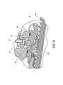
- FIG. 3is an enlarged perspective view of the translating actuator assembly of the actuator system.
- FIG. 4is a section in perspective of the translating actuator assembly through the slide key while still in intact mode, taken along line 4 - 4 of FIG. 3 .
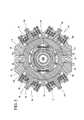
- FIG. 5is a transverse section through the slide keys and slide locks, taken along line 5 - 5 of FIG. 3 .
- FIG. 6is a regular section of the translating actuator assembly through the slide key with the slide key engaged in a tension loading mode.
- FIG. 7is a regular section of the translating actuator assembly through the slide key with the slide key engaged in a compression loading mode.
- FIG. 8is a section in perspective of the translating actuator assembly through the slide lock while still in intact mode with the major key centered (lock not engaged), taken along line 8 - 8 of FIG. 3 .
- FIG. 9is a regular section of the translating actuator assembly through the slide lock with lock engaged in tension loading mode.
- FIG. 10is a regular section of the translating actuator assembly through the slide lock with lock engaged in compression loading mode.
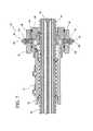
- FIG. 11is a regular section of the stationary actuator assembly showing the irreversibility mechanism, the gear assembly and the tie-rod assembly, taken along line 11 - 11 of FIG. 2 .
- FIG. 1illustrates the actuator system, designated generally as 10 , in accordance with the principles of the present invention, embodied for use with a horizontal stabilizer 12 of an aircraft.
- the actuator 10functions along its stroke to facilitate pivoting of the horizontal stabilizer (i.e. control surface) 12 as shown by numeral designation 12 ′ (aircraft configured to pitch nose up or nose down).
- the actuator systemincludes a stationary actuator assembly 16 ; a ball screw assembly 18 ; a tie-rod assembly 20 (concentric to ball screw bore and shown in subsequent figures) a translating actuator assembly 22 ; and, an irreversibility mechanism, designated generally as 24 (shown in FIG. 11 , within gear assembly 28 ).
- the stationary actuator assembly 16includes a stationary actuator assembly housing 26 ; a gear assembly 28 (including the irreversibility mechanism 24 ) supported by the stationary actuator assembly housing 26 ; a motor assembly 30 (typically a motor brake assembly) operatively associated with the gear assembly 28 ; and, a stationary primary gimbal assembly 32 mounted to the stationary actuator assembly housing 26 .
- the stationary primary gimbal assembly 32is securely connected to a primary aircraft structure 14 and a secondary aircraft structure 36 .
- the tie-rod assembly 20is positioned within the ball screw assembly 18 .
- the tie-rod assembly 20is radially locked to the ball screw assembly 18 at extremities thereof.
- a secondary clevis 38is connected to a stationary secondary aircraft structure 36 .
- a secondary locking elementis operably connected to the secondary clevis 38 .
- the tie-rod assembly 20includes a tie rod 42 (see FIG. 10 ) with a threaded end 44 including a lock nut 46 connected to the tie-rod threaded end 44 .
- a tie-rod secondary load pathis defined from the secondary aircraft structure 36 to the secondary clevis 38 , to the locking element 47 to the tie-rod 42 and to the lock nut 46 .
- the ball screw assembly 18includes a ball screw 48 ; a ball nut assembly 50 translatable along the ball screw 48 ; wiper 57 ; ice scraper 53 ; and, a secondary inverted thread nut housing 62 in a loaded tension mode operatively positioned about the ball nut assembly 50 .
- the ball nut assembly 50includes a plurality of ball circuits 58 , each ball circuit 58 containing a plurality of balls 60 .
- the secondary inverted thread nut housing 62has plurality of radially and axially spaced slots 64 .
- the ball screw assembly 18also includes an extend mechanical stop 54 positioned at an end of the ball screw 48 opposite the stationary actuator assembly 16 .
- a retract mechanical stop 56is at an opposite end of the ball screw 48 .
- the secondary inverted thread nut housing 62is accurately positioned relative to ball screw 48 and to ball nut assembly 50 . Referring now to FIG. 4 , this positioning is achieved by means of a splined radial connection 61 and a centering mechanism 63 comprising a centering ring 67 and multiple balls 65 .
- the ball screw assembly 18is naturally reversible by design under loading conditions. To make it reversible under compression and tension loading, a bi-directional mechanism is utilized. Referring again to FIG. 11 , this bi-directional irreversibility mechanism 24 is operatively connected to the stationary primary gimbal assembly 32 and to the ball screw assembly 18 .
- the irreversibility mechanism 24includes ratchets 66 , pawls 68 and skewed rollers 70 stacked above and below a ball screw flange 72 .
- the secondary inverted thread nut housing 62will be discussed below in detail.
- the translating actuator assembly 22includes a translating primary gimbal assembly 74 operatively connected to the ball screw assembly 18 , defining a translating portion of the primary load path.
- a translating secondary gimbal assembly 76is positioned about the translating primary gimbal assembly 74 and securely connected to the control surface 12 .
- a translating clevis assembly 78is operatively connected to the secondary inverted thread nut housing (SITNH) 62 and to the translating secondary gimbal assembly 76 .
- the translating clevis assembly 78contains a plurality of grooves 80 and associated openings 82 .
- At least two stationary major keys 84are mounted between the translating clevis assembly 78 and the secondary inverted thread nut housing (SITNH) 62 .
- the translating actuator assemblyincludes an axial and radial tension lock assembly 88 that includes at least one tension slide key assembly 90 housed within the translating clevis assembly 78 .
- Each tension slide key assembly 90includes a tension slide key 92 ; and, at least one spring 94 mounted on the tension slide key 92 and operably connected to the translating clevis assembly 78 , wherein during intact primary load path operation up to the structural integrity load the tension slide key 92 contacts an outer surface of the SITNH 62 in stand-by mode unaffected and unengaged by relative deflections between the primary load path and the secondary load path.
- the tension slide key 92drops and engages in an associated slot 64 in the SITNH 62 minimizing axial play.
- the translating actuator assembly 22includes an axial and radial compression lock assembly 96 .
- the axial and radial compression lock assembly 96includes at least one compression slide key assembly 98 housed within the translating clevis assembly 78 .
- Each compression slide key assembly 98includes a compression slide key 102 ; and, at least one spring 104 mounted on the compression slide key 102 and operably connected to the translating clevis assembly 78 .
- the compression slide key 102contacts an outer surface of the SITNH 62 in stand-by mode unaffected and unengaged by relative deflections between the primary load path and the secondary load path.
- the compression slide key 102drops and engages in an associated slot 64 in the SITNH 62 minimizing axial play.
- At least two retaining elements 100are securely attached to the translating clevis assembly 78 for providing the operative connection between the translating clevis assembly 78 and the translating secondary gimbal assembly 76 .
- a translating portion of the primary load path in compression and in tension directionsis defined by the load from the ball screw 48 to the ball nut assembly 50 to the translating primary gimbal assembly 74 to the control surface 12 ; wherein only the primary load path is loaded when intact.
- a translating portion of the secondary load path in compression directionis defined by the load from the ball screw 48 to the SITNH 62 to the stationary major keys 84 the compression slide key 102 and to the translating clevis assembly 78 to the retaining elements 100 to the translating secondary gimbal assembly 76 to the control surface 12 .
- the secondary load pathis unloaded, in stand-by, when the primary load path is intact in compression.
- a translating portion of the secondary load path in the tension directionis defined by the load from the ball screw 48 to the SITNH 62 to the tension slide key 92 and the stationary major keys 84 to the translating clevis assembly 78 to the retaining elements 100 to the translating secondary gimbal assembly 76 to the control surface 12 .
- the secondary load pathis unloaded, in stand-by, when the primary load path is intact in tension.
- the secondary inverted thread nut housing 62includes a split inverted thread nut 106 ; and, a set of four rollers 108 .
- the split inverted thread nut 106is divided in two halves, the split inverted nut containing multiple inverted threads 110 and are separated by multiple springs 111 .
- the split inverted nut threads 110are adapted and arranged for not contacting the ball screw 48 under a primary load path intact condition up to structural limit loading condition.
- the set of four rollers 108is positioned between the split inverted nut halves 106 and the SITNH 62 wherein the split inverted thread nut 106 contains four shallow “V” grooves 112 designed to wedge the split inverted thread nut halves 106 against the ball screw 48 when the SITNH 62 is loaded when the primary load path is failed.
- the inverted thread nut 106locks in a clockwise (CW) direction and counter clockwise (CCW) direction.
- the inverted thread nut 106locks and inhibits ball screw rotation under minimal tension load and under minimal compression axial load.
- the translating clevis assembly 78is equipped with grease zerk 113 , grease relief valve 115 and multiple glide rings 117 assuring the inner cavity (including grooves 80 ) is greased.
- the slide keys 92 and 102comprise a circular groove in its tail. This groove can be held to allow actuation (pull and release) of the slide keys 92 , 102 to exercise the springs 94 . Additionally, this circular groove will enable pulling and release of the slide keys 92 , 102 from locked and engaged positions.
- a position sensor 117is operatively connected to the stationary actuator assembly 16 by means of gearing to a worm gear 119 .
- control surfacessuch as an aileron, a wing trailing edge flap, a wing leading edge slat, an elevator, an Elevon (control surface performing roles of elevator and aileron), a Flaperon (a control surface performing roles of wing flap trailing edge and aileron), or wing (for variable wing sweep aircraft).
- tension slide keyAlthough the major key, tension slide key, compression slide key and slot have been illustrated as having square cross-sections it is understood they can have other shapes such as rectangular shapes, cylindrical, or circular.
Landscapes
- Engineering & Computer Science (AREA)
- General Engineering & Computer Science (AREA)
- Mechanical Engineering (AREA)
- Automation & Control Theory (AREA)
- Aviation & Aerospace Engineering (AREA)
- Transmission Devices (AREA)
Abstract
Description
Claims (9)
Priority Applications (1)
| Application Number | Priority Date | Filing Date | Title |
|---|---|---|---|
| US13/177,496US8496204B1 (en) | 2011-07-06 | 2011-07-06 | Method and system for minimizing axial backlash in a dual load path fail-safe aircraft actuator system |
Applications Claiming Priority (1)
| Application Number | Priority Date | Filing Date | Title |
|---|---|---|---|
| US13/177,496US8496204B1 (en) | 2011-07-06 | 2011-07-06 | Method and system for minimizing axial backlash in a dual load path fail-safe aircraft actuator system |
Publications (1)
| Publication Number | Publication Date |
|---|---|
| US8496204B1true US8496204B1 (en) | 2013-07-30 |
Family
ID=48808613
Family Applications (1)
| Application Number | Title | Priority Date | Filing Date |
|---|---|---|---|
| US13/177,496Active2031-11-10US8496204B1 (en) | 2011-07-06 | 2011-07-06 | Method and system for minimizing axial backlash in a dual load path fail-safe aircraft actuator system |
Country Status (1)
| Country | Link |
|---|---|
| US (1) | US8496204B1 (en) |
Cited By (15)
| Publication number | Priority date | Publication date | Assignee | Title |
|---|---|---|---|---|
| US20120138738A1 (en)* | 2009-03-12 | 2012-06-07 | Airbus Operations, S.L. | System for increasing controllability for an aircraft |
| US20130313358A1 (en)* | 2011-11-15 | 2013-11-28 | Parker-Hannifin Corporation | Tie Rod Lock |
| WO2016087891A1 (en)* | 2014-12-01 | 2016-06-09 | Goodrich Actuation Systems Sas | Horizontal stabiliser actuator with freeplay detecting features and method thereof |
| EP3403925A1 (en)* | 2017-05-19 | 2018-11-21 | Goodrich Actuation Systems SAS | Lower attachment system for a trimmable horizontal stabiliser actuator |
| US20190017580A1 (en)* | 2016-01-20 | 2019-01-17 | Eaton Intelligent Power Limited | Ball screw with secondary lead for failure detection |
| US10933978B2 (en) | 2017-01-10 | 2021-03-02 | Parker-Hannifin Corporation | Moving end electronic detection of secondary load path engagement of aircraft flight control actuator |
| US10974846B2 (en)* | 2016-12-09 | 2021-04-13 | Parker-Hannifin Corporation | Fixed end electronic detection of secondary load path engagement of aircraft flight control actuator |
| US11148922B2 (en)* | 2019-04-05 | 2021-10-19 | Oshkosh Corporation | Actuator failure detection systems and methods |
| US20220185448A1 (en)* | 2020-12-16 | 2022-06-16 | The Boeing Company | Trim actuators for horizontal stabilizers and methods of controlling horizontal stabilizers |
| US11479343B2 (en)* | 2018-02-13 | 2022-10-25 | The Boeing Company | Split gimbal |
| US11480235B2 (en)* | 2019-06-14 | 2022-10-25 | Goodrich Actuation Systems Sas | Actuator lower attachment |
| US11628926B2 (en) | 2018-08-02 | 2023-04-18 | Parker-Hannifin Corporation | LVDT-based actuator output load limited |
| US11820631B2 (en) | 2019-04-05 | 2023-11-21 | Oshkosh Corporation | Actuator failure detection and scissor lift load sensing systems and methods |
| US11933386B2 (en) | 2022-04-28 | 2024-03-19 | Lin Engineering, Inc. | Anti-backlash mechanism for electromechanical linear actuator |
| EP4382413A1 (en)* | 2022-12-07 | 2024-06-12 | Goodrich Actuation Systems SAS | Lower attachment for trimmable horizontal stabiliser actuator |
Citations (19)
| Publication number | Priority date | Publication date | Assignee | Title |
|---|---|---|---|---|
| US3695096A (en) | 1970-04-20 | 1972-10-03 | Ali Umit Kutsay | Strain detecting load cell |
| US4149430A (en)* | 1977-09-26 | 1979-04-17 | The United States Of America As Represented By The Secretary Of The Army | Brake for ball screw |
| US4159444A (en) | 1978-03-21 | 1979-06-26 | Sperry Rand Corporation | Fail operational dual electromechanical servo actuator for aircraft with model monitoring |
| US4594714A (en) | 1983-05-02 | 1986-06-10 | United Technologies Corporation | Dual-actuator monitor |
| US4745815A (en)* | 1986-12-08 | 1988-05-24 | Sundstrand Corporation | Non-jamming screw actuator system |
| USRE32746E (en) | 1979-09-28 | 1988-09-13 | Weico Corporation | Strain/deflection sensitive variable reluctance transducer assembly |
| US4782706A (en) | 1986-02-08 | 1988-11-08 | Vdo Adolf Schindling Ag | Holding device for mounting an electric transducer |
| US5114096A (en) | 1990-07-27 | 1992-05-19 | Wernicke Kenneth G | Tail sitter airplane |
| US5719566A (en) | 1996-06-28 | 1998-02-17 | Sundstrand Corporation | Method and apparatus for detecting dormant actuator failure |
| US6011482A (en) | 1997-11-26 | 2000-01-04 | The Boeing Company | Fastener protrusion sensor |
| US6140942A (en) | 1999-06-25 | 2000-10-31 | Board Of Trustees Of The University Of Illinois | Aircraft surface contamination sensing system using control surface hinge moment measurements |
| US6239713B1 (en) | 1999-01-29 | 2001-05-29 | Lucas Industries Limited | Sensor mounting arrangement |
| US6389915B1 (en) | 1999-05-17 | 2002-05-21 | Alliedsignal, Inc. | Dual load path ball screw with rod end swivel |
| US6622972B2 (en) | 2001-10-31 | 2003-09-23 | The Boeing Company | Method and system for in-flight fault monitoring of flight control actuators |
| US6636009B2 (en) | 2000-12-22 | 2003-10-21 | Renk Aktiengesellschaft | Fault-tolerant electromechanical actuating device |
| US6672540B1 (en) | 2002-12-03 | 2004-01-06 | Rockwell Collins, Inc. | Actuator for aircraft stabilizers with a failure responsive lock control mechanism |
| US20060170535A1 (en) | 1999-02-26 | 2006-08-03 | Sri International | Sensor devices for structural health monitoring |
| US7299702B2 (en) | 2002-07-16 | 2007-11-27 | Fgb Instrumentation | Apparatus for monitoring an aircraft flap and application of a dynamometric rod |
| US20090289145A1 (en)* | 2007-02-07 | 2009-11-26 | Behar Bruce W | Electromechanical actuating assembly |
- 2011
- 2011-07-06USUS13/177,496patent/US8496204B1/enactiveActive
Patent Citations (19)
| Publication number | Priority date | Publication date | Assignee | Title |
|---|---|---|---|---|
| US3695096A (en) | 1970-04-20 | 1972-10-03 | Ali Umit Kutsay | Strain detecting load cell |
| US4149430A (en)* | 1977-09-26 | 1979-04-17 | The United States Of America As Represented By The Secretary Of The Army | Brake for ball screw |
| US4159444A (en) | 1978-03-21 | 1979-06-26 | Sperry Rand Corporation | Fail operational dual electromechanical servo actuator for aircraft with model monitoring |
| USRE32746E (en) | 1979-09-28 | 1988-09-13 | Weico Corporation | Strain/deflection sensitive variable reluctance transducer assembly |
| US4594714A (en) | 1983-05-02 | 1986-06-10 | United Technologies Corporation | Dual-actuator monitor |
| US4782706A (en) | 1986-02-08 | 1988-11-08 | Vdo Adolf Schindling Ag | Holding device for mounting an electric transducer |
| US4745815A (en)* | 1986-12-08 | 1988-05-24 | Sundstrand Corporation | Non-jamming screw actuator system |
| US5114096A (en) | 1990-07-27 | 1992-05-19 | Wernicke Kenneth G | Tail sitter airplane |
| US5719566A (en) | 1996-06-28 | 1998-02-17 | Sundstrand Corporation | Method and apparatus for detecting dormant actuator failure |
| US6011482A (en) | 1997-11-26 | 2000-01-04 | The Boeing Company | Fastener protrusion sensor |
| US6239713B1 (en) | 1999-01-29 | 2001-05-29 | Lucas Industries Limited | Sensor mounting arrangement |
| US20060170535A1 (en) | 1999-02-26 | 2006-08-03 | Sri International | Sensor devices for structural health monitoring |
| US6389915B1 (en) | 1999-05-17 | 2002-05-21 | Alliedsignal, Inc. | Dual load path ball screw with rod end swivel |
| US6140942A (en) | 1999-06-25 | 2000-10-31 | Board Of Trustees Of The University Of Illinois | Aircraft surface contamination sensing system using control surface hinge moment measurements |
| US6636009B2 (en) | 2000-12-22 | 2003-10-21 | Renk Aktiengesellschaft | Fault-tolerant electromechanical actuating device |
| US6622972B2 (en) | 2001-10-31 | 2003-09-23 | The Boeing Company | Method and system for in-flight fault monitoring of flight control actuators |
| US7299702B2 (en) | 2002-07-16 | 2007-11-27 | Fgb Instrumentation | Apparatus for monitoring an aircraft flap and application of a dynamometric rod |
| US6672540B1 (en) | 2002-12-03 | 2004-01-06 | Rockwell Collins, Inc. | Actuator for aircraft stabilizers with a failure responsive lock control mechanism |
| US20090289145A1 (en)* | 2007-02-07 | 2009-11-26 | Behar Bruce W | Electromechanical actuating assembly |
Cited By (27)
| Publication number | Priority date | Publication date | Assignee | Title |
|---|---|---|---|---|
| US9079655B2 (en)* | 2009-03-12 | 2015-07-14 | Airbus Operations, S.L. | System for increasing controllability for an aircraft |
| US20120138738A1 (en)* | 2009-03-12 | 2012-06-07 | Airbus Operations, S.L. | System for increasing controllability for an aircraft |
| US20130313358A1 (en)* | 2011-11-15 | 2013-11-28 | Parker-Hannifin Corporation | Tie Rod Lock |
| US8985510B2 (en)* | 2011-11-15 | 2015-03-24 | Parker-Hannifin Corporation | Tie rod lock |
| US11035445B2 (en) | 2014-12-01 | 2021-06-15 | Goodrich Actuation Systems Sas | Horizontal stabiliser actuator with freeplay detecting features and method thereof |
| WO2016087891A1 (en)* | 2014-12-01 | 2016-06-09 | Goodrich Actuation Systems Sas | Horizontal stabiliser actuator with freeplay detecting features and method thereof |
| US20170335931A1 (en)* | 2014-12-01 | 2017-11-23 | Goodrich Actuation Systems Sas | Horizontal stabiliser actuator with freeplay detecting features and method thereof |
| US20190017580A1 (en)* | 2016-01-20 | 2019-01-17 | Eaton Intelligent Power Limited | Ball screw with secondary lead for failure detection |
| US11149828B2 (en)* | 2016-01-20 | 2021-10-19 | Eaton Intelligent Power Limited | Ball screw with secondary lead for failure detection |
| US10974846B2 (en)* | 2016-12-09 | 2021-04-13 | Parker-Hannifin Corporation | Fixed end electronic detection of secondary load path engagement of aircraft flight control actuator |
| US10933978B2 (en) | 2017-01-10 | 2021-03-02 | Parker-Hannifin Corporation | Moving end electronic detection of secondary load path engagement of aircraft flight control actuator |
| EP3403925A1 (en)* | 2017-05-19 | 2018-11-21 | Goodrich Actuation Systems SAS | Lower attachment system for a trimmable horizontal stabiliser actuator |
| RU2758840C2 (en)* | 2017-05-19 | 2021-11-02 | Гудрич Актюасьён Системз Сас | Lower mounting system for drive of controlled horizontal stabilizer |
| US10800515B2 (en) | 2017-05-19 | 2020-10-13 | Goodrich Actuation Systems Sas | Lower attachment system for a trimmable horizontal stabiliser actuator |
| US11479343B2 (en)* | 2018-02-13 | 2022-10-25 | The Boeing Company | Split gimbal |
| US11628926B2 (en) | 2018-08-02 | 2023-04-18 | Parker-Hannifin Corporation | LVDT-based actuator output load limited |
| US12054372B2 (en) | 2019-04-05 | 2024-08-06 | Oshkosh Corporation | Scissor lift with electric actuator |
| US11148922B2 (en)* | 2019-04-05 | 2021-10-19 | Oshkosh Corporation | Actuator failure detection systems and methods |
| US11820631B2 (en) | 2019-04-05 | 2023-11-21 | Oshkosh Corporation | Actuator failure detection and scissor lift load sensing systems and methods |
| US12421092B2 (en) | 2019-04-05 | 2025-09-23 | Oshkosh Corporation | Scissor lift with electric actuator |
| US12391530B2 (en) | 2019-04-05 | 2025-08-19 | Oshkosh Corporation | Actuator failure detection and scissor lift loadsensing systems and methods |
| US11480235B2 (en)* | 2019-06-14 | 2022-10-25 | Goodrich Actuation Systems Sas | Actuator lower attachment |
| US20220185448A1 (en)* | 2020-12-16 | 2022-06-16 | The Boeing Company | Trim actuators for horizontal stabilizers and methods of controlling horizontal stabilizers |
| US11873092B2 (en)* | 2020-12-16 | 2024-01-16 | The Boeing Company | Trim actuators for horizontal stabilizers and methods of controlling horizontal stabilizers |
| US11933386B2 (en) | 2022-04-28 | 2024-03-19 | Lin Engineering, Inc. | Anti-backlash mechanism for electromechanical linear actuator |
| EP4382413A1 (en)* | 2022-12-07 | 2024-06-12 | Goodrich Actuation Systems SAS | Lower attachment for trimmable horizontal stabiliser actuator |
| US12420911B2 (en) | 2022-12-07 | 2025-09-23 | Goodrich Actuation Systems Sas | Lower attachment for trimmable horizontal stabiliser actuator |
Similar Documents
| Publication | Publication Date | Title |
|---|---|---|
| US8496204B1 (en) | Method and system for minimizing axial backlash in a dual load path fail-safe aircraft actuator system | |
| US10538310B2 (en) | Near synchronous distributed hydraulic motor driven actuation system | |
| US7610828B2 (en) | Flight control surface actuator assembly including a free trial mechanism | |
| US8985510B2 (en) | Tie rod lock | |
| US8291782B1 (en) | Actuator assembly for stabilizers | |
| US10065728B2 (en) | Horizontal stabilizer trim actuator failure detection system and method using position sensors | |
| US7690597B2 (en) | Flap actuator | |
| US8702035B2 (en) | Actuation apparatus for use on an aircraft | |
| US8714479B1 (en) | Centering, release and reset mechanism | |
| US6851648B2 (en) | Ball screw actuator for aircraft control surfaces | |
| US5743490A (en) | Flap/slat actuation system for an aircraft | |
| EP0448711B1 (en) | Jam resistant ball screw actuator | |
| US10933978B2 (en) | Moving end electronic detection of secondary load path engagement of aircraft flight control actuator | |
| US11046425B2 (en) | Apparatus and methods for actuating a double-slotted flap using a slave screw | |
| US10974846B2 (en) | Fixed end electronic detection of secondary load path engagement of aircraft flight control actuator | |
| US6929222B2 (en) | Non-jamming, fail safe flight control system with non-symmetric load alleviation capability | |
| US20210114717A1 (en) | Aircraft actuator with no-back, load detent assembly | |
| WO2011096913A1 (en) | Structurally-redundant actuators | |
| US20070108342A1 (en) | Reconfigurable flight control surface actuation system and method | |
| US11454305B1 (en) | Jam free linear actuation system implementing a mechanical disengagement mechanism and process thereof | |
| US10591001B2 (en) | Fault tolerant actuator |
Legal Events
| Date | Code | Title | Description |
|---|---|---|---|
| AS | Assignment | Owner name:ROCKWELL COLLINS, INC., IOWA Free format text:ASSIGNMENT OF ASSIGNORS INTEREST;ASSIGNORS:CHARAFEDDINE, ABBAS M.;CHAPMAN, DOUGLAS. M;BARLOW, ROBERT S.;AND OTHERS;SIGNING DATES FROM 20110824 TO 20111006;REEL/FRAME:027030/0564 | |
| STCF | Information on status: patent grant | Free format text:PATENTED CASE | |
| FPAY | Fee payment | Year of fee payment:4 | |
| AS | Assignment | Owner name:SAFRAN ELECTRONICS & DEFENSE, AVIONICS USA, LLC, T Free format text:ASSIGNMENT OF ASSIGNORS INTEREST;ASSIGNOR:ROCKWELL COLLINS, INC.;REEL/FRAME:051432/0589 Effective date:20190208 | |
| MAFP | Maintenance fee payment | Free format text:PAYMENT OF MAINTENANCE FEE, 8TH YEAR, LARGE ENTITY (ORIGINAL EVENT CODE: M1552); ENTITY STATUS OF PATENT OWNER: LARGE ENTITY Year of fee payment:8 | |
| MAFP | Maintenance fee payment | Free format text:PAYMENT OF MAINTENANCE FEE, 12TH YEAR, LARGE ENTITY (ORIGINAL EVENT CODE: M1553); ENTITY STATUS OF PATENT OWNER: LARGE ENTITY Year of fee payment:12 |