US8495844B1 - Self-adjusting trim assembly at flexible ceiling and stationary wall junction - Google Patents
Self-adjusting trim assembly at flexible ceiling and stationary wall junctionDownload PDFInfo
- Publication number
- US8495844B1 US8495844B1US13/623,214US201213623214AUS8495844B1US 8495844 B1US8495844 B1US 8495844B1US 201213623214 AUS201213623214 AUS 201213623214AUS 8495844 B1US8495844 B1US 8495844B1
- Authority
- US
- United States
- Prior art keywords
- ceiling
- trim strip
- wall
- retainer clip
- trim
- Prior art date
- Legal status (The legal status is an assumption and is not a legal conclusion. Google has not performed a legal analysis and makes no representation as to the accuracy of the status listed.)
- Expired - Fee Related
Links
Images


Classifications
- E—FIXED CONSTRUCTIONS
- E04—BUILDING
- E04F—FINISHING WORK ON BUILDINGS, e.g. STAIRS, FLOORS
- E04F19/00—Other details of constructional parts for finishing work on buildings
- E04F19/02—Borders; Finishing strips, e.g. beadings; Light coves
- E04F19/06—Borders; Finishing strips, e.g. beadings; Light coves specially designed for securing panels or masking the edges of wall- or floor-covering elements
- E04F19/061—Borders; Finishing strips, e.g. beadings; Light coves specially designed for securing panels or masking the edges of wall- or floor-covering elements used to finish off an edge or corner of a wall or floor covering area
- E—FIXED CONSTRUCTIONS
- E04—BUILDING
- E04F—FINISHING WORK ON BUILDINGS, e.g. STAIRS, FLOORS
- E04F19/00—Other details of constructional parts for finishing work on buildings
- E04F19/02—Borders; Finishing strips, e.g. beadings; Light coves
- E04F19/04—Borders; Finishing strips, e.g. beadings; Light coves for use between floor or ceiling and wall, e.g. skirtings
- E04F19/0436—Borders; Finishing strips, e.g. beadings; Light coves for use between floor or ceiling and wall, e.g. skirtings between ceiling and wall
- E—FIXED CONSTRUCTIONS
- E04—BUILDING
- E04F—FINISHING WORK ON BUILDINGS, e.g. STAIRS, FLOORS
- E04F19/00—Other details of constructional parts for finishing work on buildings
- E04F19/02—Borders; Finishing strips, e.g. beadings; Light coves
- E04F19/04—Borders; Finishing strips, e.g. beadings; Light coves for use between floor or ceiling and wall, e.g. skirtings
- E04F19/0459—Borders; Finishing strips, e.g. beadings; Light coves for use between floor or ceiling and wall, e.g. skirtings characterised by the fixing method
- E04F19/0463—Plinths fixed by snap-action in a direction perpendicular to the wall
- E—FIXED CONSTRUCTIONS
- E04—BUILDING
- E04F—FINISHING WORK ON BUILDINGS, e.g. STAIRS, FLOORS
- E04F19/00—Other details of constructional parts for finishing work on buildings
- E04F19/02—Borders; Finishing strips, e.g. beadings; Light coves
- E04F19/04—Borders; Finishing strips, e.g. beadings; Light coves for use between floor or ceiling and wall, e.g. skirtings
- E04F2019/0404—Borders; Finishing strips, e.g. beadings; Light coves for use between floor or ceiling and wall, e.g. skirtings characterised by the material
- E04F2019/0413—Borders; Finishing strips, e.g. beadings; Light coves for use between floor or ceiling and wall, e.g. skirtings characterised by the material of metal
- E—FIXED CONSTRUCTIONS
- E04—BUILDING
- E04F—FINISHING WORK ON BUILDINGS, e.g. STAIRS, FLOORS
- E04F19/00—Other details of constructional parts for finishing work on buildings
- E04F19/02—Borders; Finishing strips, e.g. beadings; Light coves
- E04F19/04—Borders; Finishing strips, e.g. beadings; Light coves for use between floor or ceiling and wall, e.g. skirtings
- E04F2019/0404—Borders; Finishing strips, e.g. beadings; Light coves for use between floor or ceiling and wall, e.g. skirtings characterised by the material
- E04F2019/0422—Borders; Finishing strips, e.g. beadings; Light coves for use between floor or ceiling and wall, e.g. skirtings characterised by the material of organic plastics with or without reinforcements or filling materials
Definitions
- the present inventionsrelate to the components and the procedure for installing a trim assembly at a wall and ceiling junction, and, more particularly, relates to a self-adjusting trim assembly designed to hide unsightly gaps at the junction between the top of a stationary wall finish and a ceiling expected to move.
- free span concrete ceilings(poured or pre-cast spans devoid of columns and beams for intermediate support) have come into common usage. These free span structures are usually supported by interior walls or beams at the core of the building and by walls or beams at the exterior of the building.
- Exterior support structuresare frequently subject to temperature variances and forces not present on and around the interior (core) support structures.
- the dynamics involved with the exterior support structurescause them to expand, contract and move at different rates than the core structures, resulting in an anticipated flex or movement of the ceiling being supported. Therefore, non-supporting walls constructed between support structures have to be able to withstand the expected movement of the ceilings above them without sustaining damage.
- deflection allowancesare designed into those walls which include deflection framing components and a deflection gap between the top of the stationary wall finishes and the ceiling expected to move.
- the current, common options for treating a deflecting gap between a stationary wall finish and a slightly deflecting ceilingare flat taping the top of the stationary wall finish (applying paper or mesh tape and finishing compound on the wall surface only with the edge of the tape as close to the ceiling as possible without touching the ceiling) and/or caulking the gap between the top of the stationary wall finish and the ceiling.
- the caulking optionis also somewhat unsightly because slight defects (uneven cuts, jagged edges, etc.) at the top of the wall finish material are visible, dust and dirt tend to accumulate in the caulk space over time and the caulk tends to distort when the ceiling migrates in an upward or downward direction.
- a finishing bead(as illustrated in prior art FIG. 2 ) was often installed at the top of the wall finish material and finished with finishing compound prior to the installation of the caulk. If a finish bead is used to define the top edge of the wall finish material and hide defects, the caulk method is more costly for materials and more labor intensive than flat taping.
- caulktends to loose it's elasticity and bonding propensity over time, it eventually tends to allow small cracks and gaps to develop.
- caulkis a necessary component. Therefore the cost of the materials and labor for the caulk itself was not a factor in determining the best finishing application for the wall and ceiling junction.
- trims that could hide an unsightly wall/ceiling gaphave been designed through the years past.
- known trimswere not self-adjusting and do not accommodate flex in the ceilings.
- Most known existing trim systemsattached to the surfaces of the stationary wall and the stationary ceiling.
- Many known improvementsincorporated concealed brackets and fasteners. While the trims for treating the junction between a stationary wall and a stationary ceiling were functional in their designed environment, they all had one thing in common. They were designed to be applied to the surface of a finished wall and a ceiling and they did not accommodate flexing of the ceiling without distortion or system failure.
- crown molding designssuch as those shown in U.S. Pat. Nos. 5,426,901 by Jaroslav Indracek (1995), 5,433,048 by Jean P. Strasser (1995), 4,642,957 by Troy C. Edwards (1987) and 7,451,574 by Micheal Timothey Spek (2008) include many improvements in reducing costs of installation and material costs for use at the junction of a stationary wall and a stationary ceiling. While many of these designs incorporate improvements such as brackets and preformed corners to help hide fasteners and facilitate faster installations, the chief drawback to all these systems is that they were not designed for use at a junction between a stationary wall finish and a flexible ceiling.
- This inventionis a self-adjusting trim system in all it's present and future embodiments that can be used in any building where the ceilings are expected to flex due to the inherent properties of the construction materials and support structures while the wall finishes abutting the ceilings are expected to remain stationary. To allow for the expected movement of the ceiling an unsightly gap must exist between the top of the stationary wall finishes and the flexing ceiling. Most often, the ceiling system expected to exhibit some amount of flex would be made of poured concrete or pre-cast concrete that spans from an inside (core) support wall to an outside (exterior) support wall. This invention is designed to have no adverse effect on the fire and/or sound ratings of the wall and ceiling systems. A key benefit of this system, in addition to solving the problem of providing an aesthetically pleasing finish to the stationary wall and flexing ceiling junction, is that this system of components and the installation procedure is very economical.
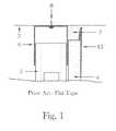
- FIG. 1illustrates a cutaway end view of the prior art of flat taping, a common way of hiding the necessary gap between the wall finish and the ceiling;
- FIG. 2shows a cutaway end view of the prior art of exposed caulking in the exposed gap, another common option where a finish bead and compound are installed on the top of the wall finish to establish a straight line defining the necessary gap between the wall finish and the ceiling which is then filled with caulk;
- FIG. 3illustrates a side view of the basic components upon which this invention is based
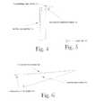
- FIG. 4is an isometric view of the Retainer Clip component of the basic system which is essential to this invention.
- FIG. 5is an isometric view of a Joint Tab which is an optional component for aligning abutted trim components of the basic system;
- FIG. 6is an isometric view of a basic trim component, hereinafter referred to as the Trim Strip of the basic system which covers gaps between wall surfaces and ceiling surfaces;
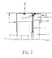
- FIG. 7illustrates a cutaway end view of the components of the basic trim system installed in a typical wall construction
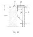
- FIG. 8illustrates a cutaway end view of the components of the basic trim system with the Retainer Clip sized to accommodate the greater distance of the wall finish from the wall framing installed in another type of typical wall construction;
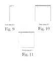
- FIG. 9is an end view of the Retainer Clip component in just one of many optional sizes
- FIG. 10is a rear view of the Retainer Clip component
- FIG. 11is a front view of the Retainer Clip component
- FIG. 12is an end view of an embodiment of the Trim Strip component
- FIG. 13is a front view of the Trim Strip component
- FIG. 14is a rear view of the Trim Strip component
- FIG. 15is an end view of the embodiments for a hook design for both the Retainer Clip and the Trim Strip component of the basic system
- FIG. 16is an end view of an alternate hook design for both the Retainer Clip and the Trim Strip component of the basic system
- FIG. 17is an end view of an alternate hook design for both the Retainer Clip and the Trim Strip component of the basic system
- FIG. 18is an end view of an alternate hook design for both the Retainer Clip and the Trim Strip component of the basic system
- FIG. 19illustrates a view of a corner in a room with the trim system installed and of the conditions behind properly installed trim after initial installation;
- FIG. 20illustrates a view of a corner in a room with the trim system installed and of the conditions behind the properly installed trim during cold weather exterior wall shrinkage when the designed gap between the static wall finish and the flex ceiling is reduced;
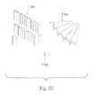
- FIG. 21illustrates a view of a corner in a room with the trim system installed and of the conditions behind the properly installed trim during hot weather exterior wall expansion when the designed gap between the static wall finish and the flex ceiling is expanded;
- FIG. 22illustrates a cutaway end view of the components of the basic trim system installed in a typical retrogressive wall construction using an alternate Retainer Clip designed to be installed after wall finishes have been previously installed;
- FIG. 23illustrates the basic components of a trim kit for a typical room.
- FIG. 24illustrates the construction process of building a wall which incorporates the trim system during construction.
- FIG. 1shows the common, aesthetic treatment of the necessary gap between the top of the stationary wall finish and the ceiling that is expected to flex due to expansion, contraction and other anticipated movement of the support walls at each end of the ceilings.
- the paper tape and finishing compound 15is applied to the top edge of the wall finish 4 with a gap between the tape and compound 15 and the ceiling 3 above.
- the framing components of this typical construction designed to allow for ceiling flexvertical framing component 5 in a deflection or slip track 6
- caulk 7in the gap between the top of the wall finish 4 and the ceiling 3 .
- a plurality of vertical framing componentsis usually contained within a wall assembly to provide the structure for the wall finishes to be used. In an assembly where the ceiling is expected to flex, the vertical framing components are expected to slide within the vertical legs of the deflection track without interfering with the up and down movement of the ceiling. For this reason, the vertical framing components and attached wall finishes are not attached to the deflection track.
- a deflection trackis a framing component that is U-shaped with a vertical leg on each side that provides lateral stability to the wall framing assembly while concurrently allowing the ceiling to which the horizontal portion is attached to move without crushing the vertical wall framing components of the assembly.
- FIG. 2shows another common aesthetic treatment of the necessary gap between the top of the stationary wall finish and the ceiling that is expected to flex.
- This treatmentshows a finishing bead with taping compound 16 at the top of the wall finish 4 .
- the necessary expansion gap between the top of the wall finish 4 and the ceiling 3is then filled with caulk 7 .
- This caulk filled gapis always noticeable.
- the caulk 7deforms and eventually allows cracks to develop between the caulk and the ceiling 3 . Due to the uneven texture and shape of the caulk 7 , dust and dirt tends to accumulate in the caulk joint.
- This treatmentis also labor intensive and costly without resulting in a permanent, aesthetically pleasing finish.
- FIG. 3is a side view of the primary components (Retainer Clip 1 and Trim Strip 2 ) of this invention (also shown during typical usage in FIGS. 7 and 8 and in special usage in FIG. 22 ).
- This inventionis essentially; a 2-piece combination of components and the method of installation that enables the Trim Strip 2 of this combination to hide the essential gap that exists in a typical wall/ceiling junction where the wall finishes 4 are stationary and the ceiling construction 3 is designed to flex in response to changes in support structure heights. The following were considerations used in designing this invention:
- FIG. 4is an isometric view of Retainer Clip 1 which shows the vertical back portion of the clip 1 a , the horizontal, projecting tongue 1 b and the location of the interlocking hook is portion 1 c .
- the horizontal tongue portion 1 b of the Retainer Clip 1acts as a spring.
- the horizontal tongue portion 1 b of the Retainer Clip 1is resilient enough to the degree that the interlocking hook 2 c of the horizontal top portion 2 a of the L-shaped Trim Strip can fit between the ceiling 3 and the horizontal projecting tongue 1 b of the Retainer Clip 1 during installation until the interlocking hook 2 c snaps into place and locks into interlocking hook 1 c of the Retainer Clip 1 .
- Retainer Clip 1causes a vertical force against the Trim Strip 2 towards the ceiling 3 thereafter.
- Retainer Clips 1may be made resilient to act like a spring when heat treated after bending. Some materials such as brass or plastics may not require heat treating to provide optimal resiliency due to inherent physical properties. (See FIGS. 15 through 18 for hook embodiments.)
- the vertical back portion of the retainer clipcould range from 1 ⁇ 4′′ to 3′′ wide and up to 4′′ high.
- the horizontal projecting tongue portion of the Retainer Clipcould range from 1 ⁇ 4′′ to 3′′ wide and from 1 ⁇ 2′′ to 3′′ deep.
- FIG. 5is an isometric view of a Joint Tab 10 that is an optional connector used to align two abutting Trim Strip 2 pieces. This connecting tab is inserted into the end at the upturned portion of each Trim Strip 2 at the joint where each butts to align the components.
- FIG. 6is an isometric view of a primary Trim Strip 2 , showing the horizontal, top portion 2 a , the vertical face portion 2 b and the hook portion 2 c .
- the Trim Strip 2is an elongated member formed of a resilient material with an L-shape in the cross section.
- the face portion 2 bis the only exposed portion of the trim system when properly installed.
- the top portion 2 ahas the interlocking hook 2 c at the end which locks into the Retainer Clip 1 at the interlocking hook portion 1 c .
- the Trim Strip 2is resilient enough to the degree that combined with the location of the interlocking hooks on the Retainer Clip 1 and the Trim Strip 2 , the resiliency of the Trim Strip 2 causes a horizontal force to press the lower end of the face portion 2 b of the Trim Strip 2 against the wall finish 4 .
- Trim Strips 2may be made resilient to act like a spring when heat treated after bending. Some materials may not require heat treating to provide optimal resiliency due to inherent physical properties.
- the face portion 2 bhas a small portion that is turned toward the wall finish 4 and up to form a stand-off that rides on the wall finish 4 without damaging the finish of the wall after installation.
- the face portion 2 bcould range from 1 ⁇ 2′′ to 2′′ high with the horizontal top portion just long enough to engage and interlock with the Retainer Clip 1 .
- the length of the Trim Strip 2is expected to range from 10 to 12′ in standard lengths.
- FIG. 7shows a typical wall framing assembly of a deflection track 6 attached to the ceiling or deck construction 3 with a concrete pin or screw 8 and a vertical framing component 5 .
- the vertical framing componentis usually a wood or metal stud and extends from the floor to within 1 ⁇ 2′′ of the ceiling.
- a wall finish 4caulk 7 and in the embodiments containing the Retainer Clip 1 and Trim Strip 2 .
- the optional Joint Tab 10can be drywall, plaster, stone, brick, paneling, stucco, acoustical panels or any other synthetic material. While most assemblies use wood or metal framing studs, other materials could be used to serve as the vertical framing component such as concrete block, clay tile, poured concrete, etc.
- An installation procedureis as follows: As shown, after the wall framing is installed, attach the Retainer Clip 1 is anchored to the deflection track. A preferred example of how to anchor the Retainer Clip 1 to the deflection track 6 is with a framing screw 9 . After the wall finish 4 is attached to the vertical framing component 5 of the framing assembly (but not to the deflection track 6 or Retainer Clip 1 ) and the caulk is installed, if required for sound or fire ratings, install the Trim Strip 2 component of the invention by forcing the horizontal portion of the Trim Strip 2 between the top of the Retainer Clip 1 and the ceiling construction 3 until it snaps into the Retainer Clip 1 hook.
- the Trim Strip 2is held tightly to the ceiling by the shape of and the tension exerted by the Retainer Clip 1 .
- the relative position of the hooks on the Retainer Clip 1 and the Trim Strip 2is engineered to provide a slight amount of lateral force on the face of the Trim Strip 2 which in conjunction with the resilient properties of the Trim Strip 2 , holds it tight to the face of the wall finish 4 .
- This illustrationshows a finish on one side of the wall framing only. However, finishes and the trim system would commonly be used on one or both sides of the framing in normal construction.
- FIG. 8shows another typical wall construction of a wall structure or framing system 11 (concrete block illustrated in this example, but it could be wood framing, metal framing, poured concrete or any other common construction system), a deflection angle 12 attached to the ceiling construction 3 by pin or screw 8 , wall furring 14 (resilient furring channel for this example) attached to the wall structure or wall framing, a wall finish 4 attached to the wall furring 14 with screw 13 , caulking backer rod 21 (used to minimize the amount of caulk required), caulk 7 and the embodiments with the Retainer Clip 1 and the Trim Strip 2 .
- This example of the usage of this inventionshows that the Retainer Clip 1 needs to be available with various tongue sizes to accommodate the variety of expected wall finish systems.
- Retainer Clips 1are much more inexpensive to manufacture in a variety of sizes than a variety of Trim Strips 2 , the variety of Retainer Clips 1 option is currently preferred.
- This illustrationshows a finish on one side of the wall framing only. However, finishes and the trim system would commonly be used on one or both sides of the framing in normal construction.
- a deflection angleserves the same function as a deflection track (previously described herein) but is usually used on one side only. Sometimes a deflection angle could be used on both sides of a wall structure where a deflection track is impractical.
- One or both of the deflection angle or the deflection trackcan be referred to by the generic term deflection component.
- Wall furringis used in some wall assemblies to improve the sound reduction coefficient of the entire assembly by adding an air space between the wall framing and the wall finishes. Wall furring is also used in some assemblies to provide backing for easier attachment of the wall finishes.
- FIGS. 9 , 10 and 11are end, rear and front views of the Retainer Clip 1 . While the vertical portion of the Retainer Clip 1 a is expected to remain approximately the same size through all embodiments, the tongue portion 1 b will be sized to accommodate various widths of wall finish treatments. Normal wall finish thicknesses in the United States are expected to range from 1 ⁇ 2′′ to 13 ⁇ 4′′. International finish thicknesses are expected to have a similar range. Special sized tongue portions 1 b should be made available on a special order basis.
- FIGS. 12 , 13 and 14are end, rear and front views of the primary Trim Strip 2 .
- the vertical and horizontal dimensions for the Trim Strip 2are expected to be a standard size in the embodiments.
- the horizontal portionhas a hook 2 c at the engagement side with the Retainer Clip 1 .
- the vertical side of the Trim Strip 2is the portion that is faced into the room after installation and is the portion that covers the gap behind.
- FIGS. 15 through 18show possible options for the hook on both the Retainer Clip 1 and the Trim Strip 2 . As shown, FIG. 15 is the preferred hook option.
- FIG. 19illustrates a typical cross-section view of a portion of a multi-story concrete building having concrete walls and ceilings or decks.
- the blow-upshows an expanded corner of a wall when looking from the room side with the Stationary Wall and Flexible Ceiling Trim System installed.
- the blow-upshows a cut-away of the Trim Strip 2 (Retainer Clip 1 not shown) to show the top of the wall finish 4 and the resulting, engineered gap filled with caulk 7 .
- a typical deflection of a ceilingis expected to flex as much as about 0.375 inches or up to about 0.4% of the room height depending on temperature variations and support structure material properties.
- FIG. 1Another cut-away shows the framing (deflection track 6 and vertical framing component 5 ) behind the wall finish 4 and the caulk 7 . Also shown is the flexible ceiling 3 and the building exterior wall 20 support structure (which is subject to wide temperature variations causing the support structure to shrink and expand as the outside temperature varies).
- FIG. 20illustrates a typical cross-section view of a portion of a multi-story concrete building having concrete walls and ceilings or decks during cold weather.
- the blow-upshows a corner of a wall when looking from the room side with the Stationary Wall and Flexible Ceiling Trim System installed.
- the cut-away on this drawingshows the effect on the engineered gap between the top of the stationary wall finish 4 and the flexing ceiling 3 .
- the caulk 7 in the gapis collapsed when the outside wall support structure 20 shrinks due to extremely cold temperatures.
- the Trim Strip 2remains in tight contact with the ceiling and completely hides the gap distortion behind.
- FIG. 21illustrates a typical cross-section view of a portion of a multi-story concrete building having concrete walls and ceilings or decks during extremely hot weather.
- the blow-upshows a corner of a wall when looking from the room side with the Stationary Wall and Flexible Ceiling Trim System installed.
- the cut-away on this drawingshows the effect on the engineered gap between the top of the stationary wall finish 4 and the flexing ceiling 3 .
- the caulk 7 in the gapis somewhat recovered (after being crushed during cold weather) when the outside wall support structure 20 expands due to extremely hot outside temperatures.
- an exaggeration 19 of the gaptends to develop between the top of the caulk 7 and the ceiling 3 as the total gap continues to grow due to the expanding of the exterior wall support structure 20 .
- the Trim Strip 2remains in tight contact with the ceiling and completely hides the gap distortion behind.
- FIG. 22illustrates a cutaway end view of the components of the basic trim system installed in a typical retrogressive wall construction using an alternate Retainer Clip designed to be installed after wall finishes have been previously installed.
- This figureshows a typical wall construction of framing components containing a deflection track 6 attached to the ceiling or deck construction 3 with a concrete pin or screw 8 and vertical framing component 5 . Also shown are a wall finish 4 , caulk 7 and the embodiments substituting Retro-fit Retainer Clips 18 (for the standard Retainer Clip 1 ) and Trim Strip 2 . Installation procedure is as follows: In spaces where the Retro-fit Retainer Clips are to be installed, existing caulk needs to be removed.
- the Retro-fit Retainer Clip 18can then be installed between the top of the deflection track 6 and the ceiling 3 using a conventional framing screw 9 to hold it in place. After the Retro-fit Retainer Clips 18 are installed, the caulk needs to be reinstalled where removed. Trim Strip 2 components of the invention are then installed by forcing the horizontal portion of the Trim Strip 2 between the top of the Retro-fit Retainer Clip 18 and the ceiling construction 3 until it snaps into the Retro-fit Retainer Clip 18 hook. Once installed, the Trim Strip 2 is held tightly to the ceiling by the shape of and the tension exerted by the Retro-fit Retainer Clip 18 .
- the relative position of the hooks on the Retro-fit Retainer Clips 18 and the Trim Strip 2is engineered to provide a slight amount of lateral force on the face of the Trim Strip 2 which in conjunction with the resilient properties of the Trim Strip 2 , holds it tight to the surface of the wall finish 4 .
- the trim systemwould commonly be used on one or both sides of the framing in normal construction.
- FIG. 23illustrates the basic components of a self-adjusting trim kit for a typical room.
- This kitcould have twenty five pieces of the Retainer Clips 1 , five pieces of the Trim Strip 2 and two pieces of Joint Tab 10 .
- several Retainer Clipswould be supplied for each Trim Strip.
- the end userwould need to select the kit sized for the wall finish to be installed. For example: If the wall finish to be used is 5 ⁇ 8′′ thick, the Retainer Clips 1 would need to be sized for the 5 ⁇ 8′′ wall finish and the end user would need to select the kit containing the 5 ⁇ 8′′ sized Retainer Clips. If the wall finish to be used is 11 ⁇ 4′′ thick, the end user would have to select a kit containing the 11 ⁇ 4′′ sized Retainer Clips. Every self-adjusting trim kit would contain the standard Trim Strip 2 and the standard Joint Tabs 10 .
- FIG. 24illustrates the steps during construction of a typical wall with the trim system installation incorporated into the final construction of the wall.
- the same installation companywould install the framing, wall finishes and the trim system.
- separate operationsare usually performed by separate installation crews within the company.
- step 101the wall partition framing is installed between the floor (not shown) and the ceiling 3 .
- the framing componentsinclude the vertical framing components 5 and the deflection track 6 . Note that the vertical framing components 5 are not attached to the deflection track 6 . Deflection track is attached to the flexing ceiling with fasteners 8 such as pins or screws. Installation of the trim system commences after step 101 .
- step 102the first step in installing the trim system involves determining the thickness of the intended wall finish 4 .
- step 103following the determination of the wall finish thickness, the appropriate Retainer Clip 1 is selected to accommodate the intended wall finish thickness.
- a Retainer Clip 1is chosen having a horizontal tongue sized according to the intended thickness of the wall finish.
- step 104a plurality of Retainer Clips 1 are installed along the length of each side of a wall to receive a wall finish by attaching to the deflection track adjacent to the ceiling 3 with screws, nails, adhesive, rivets, etc. 9 .
- step 105the trim system installer must then wait until the wall finish system is installed and finished by others.
- step 106the trim system installer measures the length of the Trim Strips to be installed and cuts the Trim Strips to the appropriate lengths.
- step 107the trim system installer then pushes the horizontal leg of the Trim Strips 2 between the top of the Retainer Clips 1 and the ceiling 3 until the trim strips lock into the Retainer Clips 1 .
- the Trim Stripwill hide the gap between the top of the wall finishes and the ceiling during all the anticipated movement of the ceiling relative to the position of the wall finish through and including normal temperature and humidity variations and even including minor earthquakes or other unexpected minor building movements.
Landscapes
- Engineering & Computer Science (AREA)
- Architecture (AREA)
- Civil Engineering (AREA)
- Structural Engineering (AREA)
- Building Environments (AREA)
- Finishing Walls (AREA)
Abstract
Description
- In finish systems where it is necessary to maintain fire ratings, metal trim components could be preferable to other known materials such as plastic trim components because metal components tend not to contribute to combustion and do not omit the toxic fumes often generated by melting or combustion of other types of materials. Being the trim component of this system is a visible finish element of the wall construction, the trim component needs to be pre-primed or pre-finished, mold resistant, moisture resistant, resistant to distortion caused by building movement and rust and corrosion resistant. While the retainer clips are not visible after complete system installation, they still need to be resistant to distortion caused by building movement and rust and corrosion resistant. Materials and fabrication of system components need to be affordable. The Retainer Clip and the Trim Strip are preferably each formed from one piece of metal or other material to make the manufacture or installation more affordable.
- The Retainer Clips1 for this system are small and light-weight, so that they are easily carried by the installer in a carpenter's pouch or nail apron. Installation of the
Retainer Clip 1 is by screw attaching with framingscrews 9 todeflection track 6 or adeflection angle 12 in a wall assembly while holding theRetainer Clip 1 up to theceiling 3. To make installation as fast as possible, spacing of clips need only be placed2″ off the ends of each wall and placed approximately 2 to 4′ on center between the ends (insuring that the framing screws9 do not engage thevertical framing component 5 portion of the framing so that movement of thedeflection track 6 ordeflection angle 12 is not inhibited). Exact spacing ofRetainer Clips 1 is not required (except at joints of the Trim Strips2 where the wall length exceeds the standard length of trim components2). Therefore, installation time for installingRetainer Clips 1 is minimized. The system requires theTrim Strip 2 to be snapped into theRetainer Clips 1 after being measured and cut for length. Where Trim Strips2 intersect each other or where they are required to abut each other in long wall instances, they have square cut ends during manufacture and are able to be abutted without requiring mitering, special connecting pieces or special cuts. In special instances where it is necessary to maintain alignment where slight deviations in the wall surfaces tend to misalign the butt joints of the Trim Strips2, a Joint Tab10 (shown inFIG. 3 ) may be used. The cost to install these components is off-set by the elimination of flat-taping or the taping and finishing of a tape bead at the top of the wall finish as shown inFIGS. 1 and 2 , making this system extremely cost efficient.
- The Retainer Clips1 for this system are small and light-weight, so that they are easily carried by the installer in a carpenter's pouch or nail apron. Installation of the
- This system does not hinder in any way, the installation or performance of the framing or finishes in constructing the wall. In new construction, it does, however require the installation of the
Retainer Clips 1 between the wall framing and the installation of the wall finishes. TheTrim Strip 2 is installed after the wall finishes are installed. In instances where the walls were finished previously and where it is desired to provide this self-adjusting trim system at a later date,Retainer Clip 18 may be substituted for the basicsystem Retainer Clip 1 so that the existing wall finishes do not need to be disturbed in order to install this system. TheTrim Strip 2 is then installed in the normal manner. Where fire caulk is a necessary component of a fire rated wall system, this molding system allows for the complete, economical installation of the caulk. This system allows for the complete, economical installation of wall framing, wall finishes and caulk, where specified, without slowing any operation or without hindering the operation of any system.
- This system does not hinder in any way, the installation or performance of the framing or finishes in constructing the wall. In new construction, it does, however require the installation of the
Claims (20)
Priority Applications (1)
| Application Number | Priority Date | Filing Date | Title |
|---|---|---|---|
| US13/623,214US8495844B1 (en) | 2012-09-20 | 2012-09-20 | Self-adjusting trim assembly at flexible ceiling and stationary wall junction |
Applications Claiming Priority (1)
| Application Number | Priority Date | Filing Date | Title |
|---|---|---|---|
| US13/623,214US8495844B1 (en) | 2012-09-20 | 2012-09-20 | Self-adjusting trim assembly at flexible ceiling and stationary wall junction |
Publications (1)
| Publication Number | Publication Date |
|---|---|
| US8495844B1true US8495844B1 (en) | 2013-07-30 |
Family
ID=48808588
Family Applications (1)
| Application Number | Title | Priority Date | Filing Date |
|---|---|---|---|
| US13/623,214Expired - Fee RelatedUS8495844B1 (en) | 2012-09-20 | 2012-09-20 | Self-adjusting trim assembly at flexible ceiling and stationary wall junction |
Country Status (1)
| Country | Link |
|---|---|
| US (1) | US8495844B1 (en) |
Cited By (36)
| Publication number | Priority date | Publication date | Assignee | Title |
|---|---|---|---|---|
| US20130031856A1 (en)* | 2010-04-08 | 2013-02-07 | California Expanded Metal Products Company | Fire-rated wall construction product |
| US8973319B2 (en) | 2007-08-06 | 2015-03-10 | California Expanded Metal Products Company | Two-piece track system |
| US9045899B2 (en) | 2012-01-20 | 2015-06-02 | California Expanded Metal Products Company | Fire-rated joint system |
| US9127454B2 (en) | 2007-08-22 | 2015-09-08 | California Expanded Metal Products Company | Fire-rated wall and ceiling system |
| USD750809S1 (en)* | 2014-07-28 | 2016-03-01 | Certainteed Corporation | Trim assembly |
| USD754881S1 (en)* | 2014-06-24 | 2016-04-26 | William Michael Hatch | Panel divider trim |
| USD754882S1 (en)* | 2014-06-24 | 2016-04-26 | William Michael Hatch | Combined panel trim and flashing |
| US9371644B2 (en) | 2009-09-21 | 2016-06-21 | California Expanded Metal Products Company | Wall gap fire block device, system and method |
| US20160208484A1 (en)* | 2015-01-16 | 2016-07-21 | California Expanded Metal Products Company | Fire blocking reveal |
| USD762878S1 (en)* | 2014-06-24 | 2016-08-02 | William Michael Hatch | Inside corner trim |
| US9441381B2 (en) | 2014-06-24 | 2016-09-13 | Stainless Architectural Supply, Llc | Construction element |
| USD767169S1 (en)* | 2014-06-24 | 2016-09-20 | William Michael Hatch | Outside corner trim |
| USD767168S1 (en)* | 2014-06-24 | 2016-09-20 | William Michael Hatch | Panel edge finishing trim |
| US9523193B2 (en) | 2012-01-20 | 2016-12-20 | California Expanded Metal Products Company | Fire-rated joint system |
| US9534402B2 (en) | 2013-08-09 | 2017-01-03 | Certainteed Corporation | System, method and apparatus for trim for building products |
| US9683364B2 (en) | 2010-04-08 | 2017-06-20 | California Expanded Metal Products Company | Fire-rated wall construction product |
| US9879421B2 (en) | 2014-10-06 | 2018-01-30 | California Expanded Metal Products Company | Fire-resistant angle and related assemblies |
| US9909298B2 (en) | 2015-01-27 | 2018-03-06 | California Expanded Metal Products Company | Header track with stud retention feature |
| US10000923B2 (en) | 2015-01-16 | 2018-06-19 | California Expanded Metal Products Company | Fire blocking reveal |
| US10077550B2 (en) | 2012-01-20 | 2018-09-18 | California Expanded Metal Products Company | Fire-rated joint system |
| US10184246B2 (en) | 2010-04-08 | 2019-01-22 | California Expanded Metal Products Company | Fire-rated wall construction product |
| US20190360195A1 (en)* | 2018-03-15 | 2019-11-28 | California Expanded Metal Products Company | Fire-rated joint component and wall assembly |
| CN110670848A (en)* | 2019-10-12 | 2020-01-10 | 上海建工五建集团有限公司 | A kind of finished wall panel closing member and manufacturing method thereof |
| US10563399B2 (en)* | 2007-08-06 | 2020-02-18 | California Expanded Metal Products Company | Two-piece track system |
| US20200080300A1 (en)* | 2018-08-16 | 2020-03-12 | California Expanded Metal Products Company | Fire or sound blocking components and wall assemblies with fire or sound blocking components |
| US10619347B2 (en) | 2007-08-22 | 2020-04-14 | California Expanded Metal Products Company | Fire-rated wall and ceiling system |
| US10689842B2 (en) | 2018-03-15 | 2020-06-23 | California Expanded Metal Products Company | Multi-layer fire-rated joint component |
| US10900243B2 (en)* | 2019-05-24 | 2021-01-26 | Terry Koethe | Two-piece trim assembly for siding on buildings |
| US10914065B2 (en) | 2019-01-24 | 2021-02-09 | California Expanded Metal Products Company | Wall joint or sound block component and wall assemblies |
| US11162259B2 (en) | 2018-04-30 | 2021-11-02 | California Expanded Metal Products Company | Mechanically fastened firestop flute plug |
| US11268274B2 (en)* | 2019-03-04 | 2022-03-08 | California Expanded Metal Products Company | Two-piece deflection drift angle |
| US11313121B2 (en)* | 2017-08-08 | 2022-04-26 | Saint-Gobain Placo S.A.S. | Dry partition wall system and method for installation of a dry partition wall system of this kind |
| US11608647B2 (en) | 2018-05-23 | 2023-03-21 | Sas Ip, Llc | Crown elements, baseboard elements, splines, and related methods |
| WO2023183871A1 (en)* | 2022-03-24 | 2023-09-28 | Freedom Metals Manufacturing, Inc. | Exterior trim system |
| US11920343B2 (en) | 2019-12-02 | 2024-03-05 | Cemco, Llc | Fire-rated wall joint component and related assemblies |
| US12215498B2 (en) | 2012-01-20 | 2025-02-04 | Cemco, Llc | Fire-rated joint system |
Citations (36)
| Publication number | Priority date | Publication date | Assignee | Title |
|---|---|---|---|---|
| US3292328A (en)* | 1962-06-08 | 1966-12-20 | Stanley T Lewis | Self-supporting panel partition with magnetic latch means therefor |
| US3309826A (en)* | 1964-01-24 | 1967-03-21 | Daniel L Zinn | Resiliently mounted dry wall partition for building structures |
| US3623290A (en)* | 1969-07-25 | 1971-11-30 | Lucien R Downing Jr | Partition wall |
| US3685227A (en)* | 1969-07-03 | 1972-08-22 | Incormac Sa | Plinth and/or framing elements for partitions and partitions applying such elements |
| US3722163A (en)* | 1969-07-31 | 1973-03-27 | Architectural Partitions | Apparatus for constructing removable partition walls |
| US3732657A (en)* | 1970-10-05 | 1973-05-15 | United States Gypsum Co | Demountable partition assembly and studs therefor |
| US3998027A (en)* | 1972-06-08 | 1976-12-21 | United States Gypsum Company | Decorative runner and wall |
| US4073108A (en)* | 1974-04-25 | 1978-02-14 | Williams Arthur C | Method and apparatus for rigidly interconnected ceiling and wall construction |
| US4087944A (en)* | 1973-08-03 | 1978-05-09 | Dynamit Nobel Aktiengesellschaft | Movable partition arrangement |
| US4209953A (en)* | 1977-08-15 | 1980-07-01 | United States Gypsum Company | Ceiling runner attachment system and clip therefor |
| US4229918A (en)* | 1977-06-22 | 1980-10-28 | Andre Delcroix | Complementary elements assembleable into a partition for preexisting wall-partitions |
| US4361994A (en)* | 1980-08-11 | 1982-12-07 | Carver Tommy L | Structural support for interior wall partition assembly |
| US4397127A (en)* | 1980-09-22 | 1983-08-09 | Donn, Incorporated | Extendable stud for partition walls or the like |
| US4461135A (en) | 1981-11-02 | 1984-07-24 | Michael W. Ognanovich | Wallboard trim apparatus |
| US4513557A (en)* | 1984-02-22 | 1985-04-30 | United States Gypsum Company | Clip for use with runner and runner assembly including the clip |
| US4555885A (en) | 1983-05-05 | 1985-12-03 | Polymer/Raymond Industries, Inc. | Filler strip with locking clip |
| US4575979A (en)* | 1984-08-08 | 1986-03-18 | Leonardo Mariani | Bracket assembly for securing wall members |
| US4642957A (en)* | 1984-12-11 | 1987-02-17 | Edwards Troy C | Interior wall trim system |
| US4798035A (en)* | 1986-06-02 | 1989-01-17 | Architectural Wall Systems, Inc. | Floor-to-ceiling wall system |
| US4881352A (en)* | 1987-07-30 | 1989-11-21 | Karl Glockenstein | Wall panel arrangement |
| US4887401A (en)* | 1988-04-18 | 1989-12-19 | Gioscia Thomas J | Knock down partition wall assembly |
| US5138759A (en)* | 1991-07-30 | 1992-08-18 | Johnson Level & Tool Mfg. Co. | Cutting guide and method of making |
| US5426901A (en) | 1993-08-27 | 1995-06-27 | Indracek; Jaroslav | Molding assembly |
| US5433048A (en) | 1990-09-23 | 1995-07-18 | Nmc S.A. | Molding of synthetic resin foam with hidden fittings |
| US5644877A (en)* | 1995-07-25 | 1997-07-08 | Wood; Richard J. | Demountable ceiling closure |
| US5755066A (en)* | 1993-12-02 | 1998-05-26 | Becker; Duane William | Slip track assembly |
| US5813179A (en)* | 1996-03-01 | 1998-09-29 | Trim-Tex, Inc. | Drywall-trimming assembly employing perforated splice |
| US5822935A (en)* | 1996-12-19 | 1998-10-20 | Steelcase Inc. | Solid-core wall system |
| US6128877A (en)* | 1998-03-10 | 2000-10-10 | Steelcase Development Inc. | Variable width end panel |
| US6158179A (en)* | 1998-03-10 | 2000-12-12 | Steelcase Development Inc. | Overhead structures for wall system |
| US6581353B2 (en) | 2001-10-09 | 2003-06-24 | Ronald J. Augustine | Support for a wall above a floating slab |
| US20060156679A1 (en)* | 2005-01-14 | 2006-07-20 | Pierret Dennis M | Crown molding and deck material attachments |
| US7313891B2 (en)* | 2005-04-20 | 2008-01-01 | Showers Robert J | Wall finishing system |
| US7451574B2 (en) | 2005-03-07 | 2008-11-18 | Spexco, Llc | Crown molding |
| US7571578B2 (en)* | 2003-10-08 | 2009-08-11 | Nucon Steel Corporation | Thermal wall system |
| US8161705B2 (en)* | 2009-03-23 | 2012-04-24 | Pratt James M | Wall panel system |
- 2012
- 2012-09-20USUS13/623,214patent/US8495844B1/ennot_activeExpired - Fee Related
Patent Citations (36)
| Publication number | Priority date | Publication date | Assignee | Title |
|---|---|---|---|---|
| US3292328A (en)* | 1962-06-08 | 1966-12-20 | Stanley T Lewis | Self-supporting panel partition with magnetic latch means therefor |
| US3309826A (en)* | 1964-01-24 | 1967-03-21 | Daniel L Zinn | Resiliently mounted dry wall partition for building structures |
| US3685227A (en)* | 1969-07-03 | 1972-08-22 | Incormac Sa | Plinth and/or framing elements for partitions and partitions applying such elements |
| US3623290A (en)* | 1969-07-25 | 1971-11-30 | Lucien R Downing Jr | Partition wall |
| US3722163A (en)* | 1969-07-31 | 1973-03-27 | Architectural Partitions | Apparatus for constructing removable partition walls |
| US3732657A (en)* | 1970-10-05 | 1973-05-15 | United States Gypsum Co | Demountable partition assembly and studs therefor |
| US3998027A (en)* | 1972-06-08 | 1976-12-21 | United States Gypsum Company | Decorative runner and wall |
| US4087944A (en)* | 1973-08-03 | 1978-05-09 | Dynamit Nobel Aktiengesellschaft | Movable partition arrangement |
| US4073108A (en)* | 1974-04-25 | 1978-02-14 | Williams Arthur C | Method and apparatus for rigidly interconnected ceiling and wall construction |
| US4229918A (en)* | 1977-06-22 | 1980-10-28 | Andre Delcroix | Complementary elements assembleable into a partition for preexisting wall-partitions |
| US4209953A (en)* | 1977-08-15 | 1980-07-01 | United States Gypsum Company | Ceiling runner attachment system and clip therefor |
| US4361994A (en)* | 1980-08-11 | 1982-12-07 | Carver Tommy L | Structural support for interior wall partition assembly |
| US4397127A (en)* | 1980-09-22 | 1983-08-09 | Donn, Incorporated | Extendable stud for partition walls or the like |
| US4461135A (en) | 1981-11-02 | 1984-07-24 | Michael W. Ognanovich | Wallboard trim apparatus |
| US4555885A (en) | 1983-05-05 | 1985-12-03 | Polymer/Raymond Industries, Inc. | Filler strip with locking clip |
| US4513557A (en)* | 1984-02-22 | 1985-04-30 | United States Gypsum Company | Clip for use with runner and runner assembly including the clip |
| US4575979A (en)* | 1984-08-08 | 1986-03-18 | Leonardo Mariani | Bracket assembly for securing wall members |
| US4642957A (en)* | 1984-12-11 | 1987-02-17 | Edwards Troy C | Interior wall trim system |
| US4798035A (en)* | 1986-06-02 | 1989-01-17 | Architectural Wall Systems, Inc. | Floor-to-ceiling wall system |
| US4881352A (en)* | 1987-07-30 | 1989-11-21 | Karl Glockenstein | Wall panel arrangement |
| US4887401A (en)* | 1988-04-18 | 1989-12-19 | Gioscia Thomas J | Knock down partition wall assembly |
| US5433048A (en) | 1990-09-23 | 1995-07-18 | Nmc S.A. | Molding of synthetic resin foam with hidden fittings |
| US5138759A (en)* | 1991-07-30 | 1992-08-18 | Johnson Level & Tool Mfg. Co. | Cutting guide and method of making |
| US5426901A (en) | 1993-08-27 | 1995-06-27 | Indracek; Jaroslav | Molding assembly |
| US5755066A (en)* | 1993-12-02 | 1998-05-26 | Becker; Duane William | Slip track assembly |
| US5644877A (en)* | 1995-07-25 | 1997-07-08 | Wood; Richard J. | Demountable ceiling closure |
| US5813179A (en)* | 1996-03-01 | 1998-09-29 | Trim-Tex, Inc. | Drywall-trimming assembly employing perforated splice |
| US5822935A (en)* | 1996-12-19 | 1998-10-20 | Steelcase Inc. | Solid-core wall system |
| US6128877A (en)* | 1998-03-10 | 2000-10-10 | Steelcase Development Inc. | Variable width end panel |
| US6158179A (en)* | 1998-03-10 | 2000-12-12 | Steelcase Development Inc. | Overhead structures for wall system |
| US6581353B2 (en) | 2001-10-09 | 2003-06-24 | Ronald J. Augustine | Support for a wall above a floating slab |
| US7571578B2 (en)* | 2003-10-08 | 2009-08-11 | Nucon Steel Corporation | Thermal wall system |
| US20060156679A1 (en)* | 2005-01-14 | 2006-07-20 | Pierret Dennis M | Crown molding and deck material attachments |
| US7451574B2 (en) | 2005-03-07 | 2008-11-18 | Spexco, Llc | Crown molding |
| US7313891B2 (en)* | 2005-04-20 | 2008-01-01 | Showers Robert J | Wall finishing system |
| US8161705B2 (en)* | 2009-03-23 | 2012-04-24 | Pratt James M | Wall panel system |
Cited By (84)
| Publication number | Priority date | Publication date | Assignee | Title |
|---|---|---|---|---|
| US10563399B2 (en)* | 2007-08-06 | 2020-02-18 | California Expanded Metal Products Company | Two-piece track system |
| US12252881B2 (en) | 2007-08-06 | 2025-03-18 | Cemco, Llc | Two-piece track system |
| US8973319B2 (en) | 2007-08-06 | 2015-03-10 | California Expanded Metal Products Company | Two-piece track system |
| US9739054B2 (en)* | 2007-08-06 | 2017-08-22 | California Expanded Metal Products Company | Two-piece track system |
| US9995039B2 (en) | 2007-08-06 | 2018-06-12 | California Expanded Metal Products Company | Two-piece track system |
| US11773587B2 (en) | 2007-08-06 | 2023-10-03 | Cemco, Llc | Two-piece track system |
| US11560712B2 (en) | 2007-08-06 | 2023-01-24 | Cemco, Llc | Two-piece track system |
| US9290934B2 (en) | 2007-08-06 | 2016-03-22 | California Expanded Metal Products Company | Two-piece track system |
| US10227775B2 (en) | 2007-08-06 | 2019-03-12 | California Expanded Metal Products Company | Two-piece track system |
| US11041306B2 (en) | 2007-08-06 | 2021-06-22 | California Expanded Metal Products Company | Two-piece track system |
| US9127454B2 (en) | 2007-08-22 | 2015-09-08 | California Expanded Metal Products Company | Fire-rated wall and ceiling system |
| US10619347B2 (en) | 2007-08-22 | 2020-04-14 | California Expanded Metal Products Company | Fire-rated wall and ceiling system |
| US11466449B2 (en) | 2007-08-22 | 2022-10-11 | California Expanded Metal Products Company | Fire-rated wall and ceiling system |
| US10214901B2 (en) | 2007-08-22 | 2019-02-26 | California Expanded Metal Products Company | Fire-rated wall and ceiling system |
| US10011983B2 (en) | 2007-08-22 | 2018-07-03 | California Expanded Metal Products Company | Fire-rated wall and ceiling system |
| US9637914B2 (en) | 2007-08-22 | 2017-05-02 | California Expanded Metal Products Company | Fire-rated wall and ceiling system |
| US9739052B2 (en) | 2007-08-22 | 2017-08-22 | California Expanded Metal Products Company | Fire-rated wall and ceiling system |
| US9481998B2 (en) | 2007-08-22 | 2016-11-01 | California Expanded Metal Products Company | Fire-rated wall and ceiling system |
| US11802404B2 (en) | 2007-08-22 | 2023-10-31 | Cemco, Llc | Fire-rated wall and ceiling system |
| US9616259B2 (en) | 2009-09-21 | 2017-04-11 | California Expanded Metal Products Company | Wall gap fire block device, system and method |
| US9931527B2 (en) | 2009-09-21 | 2018-04-03 | California Expanded Metal Products Company | Wall gap fire block device, system and method |
| US10406389B2 (en) | 2009-09-21 | 2019-09-10 | California Expanded Metal Products Company | Wall gap fire block device, system and method |
| US11141613B2 (en) | 2009-09-21 | 2021-10-12 | California Expanded Metal Products Company | Wall gap fire block device, system and method |
| US9371644B2 (en) | 2009-09-21 | 2016-06-21 | California Expanded Metal Products Company | Wall gap fire block device, system and method |
| US11896859B2 (en) | 2009-09-21 | 2024-02-13 | Cemco, Llc | Wall gap fire block device, system and method |
| US9290932B2 (en) | 2010-04-08 | 2016-03-22 | California Expanded Metal Products Company | Fire-rated wall construction product |
| US10184246B2 (en) | 2010-04-08 | 2019-01-22 | California Expanded Metal Products Company | Fire-rated wall construction product |
| US20130031856A1 (en)* | 2010-04-08 | 2013-02-07 | California Expanded Metal Products Company | Fire-rated wall construction product |
| US11905705B2 (en) | 2010-04-08 | 2024-02-20 | Cemco, Llc | Fire-rated wall construction product |
| US12428836B2 (en) | 2010-04-08 | 2025-09-30 | Cemco, Llc | Fire-rated wall construction product |
| US8793947B2 (en)* | 2010-04-08 | 2014-08-05 | California Expanded Metal Products Company | Fire-rated wall construction product |
| US20190360199A1 (en)* | 2010-04-08 | 2019-11-28 | California Expanded Metal Products Company | Fire-rated wall construction product |
| US11060283B2 (en)* | 2010-04-08 | 2021-07-13 | California Expanded Metal Products Company | Fire-rated wall construction product |
| US9683364B2 (en) | 2010-04-08 | 2017-06-20 | California Expanded Metal Products Company | Fire-rated wall construction product |
| US11898346B2 (en) | 2012-01-20 | 2024-02-13 | Cemco, Llc | Fire-rated joint system |
| US9523193B2 (en) | 2012-01-20 | 2016-12-20 | California Expanded Metal Products Company | Fire-rated joint system |
| US10077550B2 (en) | 2012-01-20 | 2018-09-18 | California Expanded Metal Products Company | Fire-rated joint system |
| US10246871B2 (en) | 2012-01-20 | 2019-04-02 | California Expanded Metal Products Company | Fire-rated joint system |
| US9045899B2 (en) | 2012-01-20 | 2015-06-02 | California Expanded Metal Products Company | Fire-rated joint system |
| US9458628B2 (en) | 2012-01-20 | 2016-10-04 | California Expanded Metal Products Company | Fire-rated joint system |
| US12215498B2 (en) | 2012-01-20 | 2025-02-04 | Cemco, Llc | Fire-rated joint system |
| US10900223B2 (en) | 2012-01-20 | 2021-01-26 | California Expanded Metal Products Company | Fire-rated joint system |
| US9534402B2 (en) | 2013-08-09 | 2017-01-03 | Certainteed Corporation | System, method and apparatus for trim for building products |
| USD754882S1 (en)* | 2014-06-24 | 2016-04-26 | William Michael Hatch | Combined panel trim and flashing |
| USD767169S1 (en)* | 2014-06-24 | 2016-09-20 | William Michael Hatch | Outside corner trim |
| US10648185B2 (en) | 2014-06-24 | 2020-05-12 | Sas Ip, Llc | Baseboard elements and related method |
| US9441381B2 (en) | 2014-06-24 | 2016-09-13 | Stainless Architectural Supply, Llc | Construction element |
| US11156006B2 (en) | 2014-06-24 | 2021-10-26 | Sas Ip, Llc | Baseboard elements and related method |
| USD762878S1 (en)* | 2014-06-24 | 2016-08-02 | William Michael Hatch | Inside corner trim |
| USD754881S1 (en)* | 2014-06-24 | 2016-04-26 | William Michael Hatch | Panel divider trim |
| US12163338B2 (en) | 2014-06-24 | 2024-12-10 | Sas Ip, Llc | Baseboard elements and related method |
| USD767168S1 (en)* | 2014-06-24 | 2016-09-20 | William Michael Hatch | Panel edge finishing trim |
| USD750809S1 (en)* | 2014-07-28 | 2016-03-01 | Certainteed Corporation | Trim assembly |
| USD797956S1 (en) | 2014-07-28 | 2017-09-19 | Certainteed Corporation | Trim assembly |
| US9879421B2 (en) | 2014-10-06 | 2018-01-30 | California Expanded Metal Products Company | Fire-resistant angle and related assemblies |
| US10000923B2 (en) | 2015-01-16 | 2018-06-19 | California Expanded Metal Products Company | Fire blocking reveal |
| US20160208484A1 (en)* | 2015-01-16 | 2016-07-21 | California Expanded Metal Products Company | Fire blocking reveal |
| US9752318B2 (en)* | 2015-01-16 | 2017-09-05 | California Expanded Metal Products Company | Fire blocking reveal |
| US9909298B2 (en) | 2015-01-27 | 2018-03-06 | California Expanded Metal Products Company | Header track with stud retention feature |
| US11313121B2 (en)* | 2017-08-08 | 2022-04-26 | Saint-Gobain Placo S.A.S. | Dry partition wall system and method for installation of a dry partition wall system of this kind |
| US11866932B2 (en) | 2018-03-15 | 2024-01-09 | Cemco, Llc | Fire-rated joint component and wall assembly |
| US10689842B2 (en) | 2018-03-15 | 2020-06-23 | California Expanded Metal Products Company | Multi-layer fire-rated joint component |
| US11421417B2 (en)* | 2018-03-15 | 2022-08-23 | California Expanded Metal Products Company | Fire-rated joint component and wall assembly |
| US12312802B2 (en) | 2018-03-15 | 2025-05-27 | Cemco, Llc | Fire-rated joint component and wall assembly |
| US10753084B2 (en)* | 2018-03-15 | 2020-08-25 | California Expanded Metal Products Company | Fire-rated joint component and wall assembly |
| US10954670B2 (en) | 2018-03-15 | 2021-03-23 | California Expanded Metal Products Company | Multi-layer fire-rated joint component |
| US20190360195A1 (en)* | 2018-03-15 | 2019-11-28 | California Expanded Metal Products Company | Fire-rated joint component and wall assembly |
| US11162259B2 (en) | 2018-04-30 | 2021-11-02 | California Expanded Metal Products Company | Mechanically fastened firestop flute plug |
| US11933042B2 (en) | 2018-04-30 | 2024-03-19 | Cemco, Llc | Mechanically fastened firestop flute plug |
| US11608647B2 (en) | 2018-05-23 | 2023-03-21 | Sas Ip, Llc | Crown elements, baseboard elements, splines, and related methods |
| US12371911B2 (en) | 2018-05-23 | 2025-07-29 | Sas Ip, Llc | Crown elements, baseboard elements, splines, and related methods |
| US11111666B2 (en)* | 2018-08-16 | 2021-09-07 | California Expanded Metal Products Company | Fire or sound blocking components and wall assemblies with fire or sound blocking components |
| US20200080300A1 (en)* | 2018-08-16 | 2020-03-12 | California Expanded Metal Products Company | Fire or sound blocking components and wall assemblies with fire or sound blocking components |
| US11873636B2 (en) | 2018-08-16 | 2024-01-16 | Cemco, Llc | Fire or sound blocking components and wall assemblies with fire or sound blocking components |
| US11280084B2 (en)* | 2019-01-24 | 2022-03-22 | California Expanded Metal Prod ucts Company | Wall joint or sound block component and wall assemblies |
| US11891800B2 (en) | 2019-01-24 | 2024-02-06 | Cemco, Llc | Wall joint or sound block component and wall assemblies |
| US10914065B2 (en) | 2019-01-24 | 2021-02-09 | California Expanded Metal Products Company | Wall joint or sound block component and wall assemblies |
| US20220259852A1 (en)* | 2019-03-04 | 2022-08-18 | California Expanded Metal Products Company | Two-piece deflection drift angle |
| US11920344B2 (en)* | 2019-03-04 | 2024-03-05 | Cemco, Llc | Two-piece deflection drift angle |
| US11268274B2 (en)* | 2019-03-04 | 2022-03-08 | California Expanded Metal Products Company | Two-piece deflection drift angle |
| US10900243B2 (en)* | 2019-05-24 | 2021-01-26 | Terry Koethe | Two-piece trim assembly for siding on buildings |
| CN110670848A (en)* | 2019-10-12 | 2020-01-10 | 上海建工五建集团有限公司 | A kind of finished wall panel closing member and manufacturing method thereof |
| US11920343B2 (en) | 2019-12-02 | 2024-03-05 | Cemco, Llc | Fire-rated wall joint component and related assemblies |
| WO2023183871A1 (en)* | 2022-03-24 | 2023-09-28 | Freedom Metals Manufacturing, Inc. | Exterior trim system |
Similar Documents
| Publication | Publication Date | Title |
|---|---|---|
| US8495844B1 (en) | Self-adjusting trim assembly at flexible ceiling and stationary wall junction | |
| US12428836B2 (en) | Fire-rated wall construction product | |
| US9290932B2 (en) | Fire-rated wall construction product | |
| US11773587B2 (en) | Two-piece track system | |
| US9683364B2 (en) | Fire-rated wall construction product | |
| US7757450B2 (en) | Control joint | |
| US10000923B2 (en) | Fire blocking reveal | |
| US8240099B2 (en) | Architectural panel system | |
| US9677283B2 (en) | Building veneer system | |
| US9140007B2 (en) | Rain screen framing system | |
| AU2011242143B2 (en) | Cladding rail, cladding fixing system and method | |
| US20080005986A1 (en) | Floating-wall base and method of installation | |
| US20100139210A1 (en) | Surface coverings including decorative strips | |
| US8464485B2 (en) | Fire resistive joint cover system | |
| US10024062B2 (en) | Building veneer system | |
| US20160362898A1 (en) | Apparatus providing visual-reveal gap for wall | |
| US10267038B2 (en) | Ceiling system | |
| US7047702B1 (en) | Perimeter angle trim | |
| US12091863B2 (en) | Flood resistant wall | |
| US12024897B2 (en) | Quad spacer for installation of flooring systems | |
| CA2867967C (en) | Building veneer system | |
| US20090064620A1 (en) | Tray Ceiling System | |
| IT201800004551A1 (en) | VENTILATED WALL SYSTEM | |
| CA2962478A1 (en) | Fire-rated wall construction product | |
| CA2954124A1 (en) | Fire-rated wall construction product |
Legal Events
| Date | Code | Title | Description |
|---|---|---|---|
| FEPP | Fee payment procedure | Free format text:PATENT HOLDER CLAIMS MICRO ENTITY STATUS, ENTITY STATUS SET TO MICRO (ORIGINAL EVENT CODE: STOM); ENTITY STATUS OF PATENT OWNER: MICROENTITY | |
| STCF | Information on status: patent grant | Free format text:PATENTED CASE | |
| AS | Assignment | Owner name:DGT CORP., ILLINOIS Free format text:ASSIGNMENT OF ASSIGNORS INTEREST;ASSIGNOR:JOHNSON, THOMAS W;REEL/FRAME:035495/0906 Effective date:20150425 | |
| FPAY | Fee payment | Year of fee payment:4 | |
| MAFP | Maintenance fee payment | Free format text:PAYMENT OF MAINTENANCE FEE, 8TH YEAR, MICRO ENTITY (ORIGINAL EVENT CODE: M3552); ENTITY STATUS OF PATENT OWNER: MICROENTITY Year of fee payment:8 | |
| FEPP | Fee payment procedure | Free format text:MAINTENANCE FEE REMINDER MAILED (ORIGINAL EVENT CODE: REM.); ENTITY STATUS OF PATENT OWNER: MICROENTITY | |
| LAPS | Lapse for failure to pay maintenance fees | Free format text:PATENT EXPIRED FOR FAILURE TO PAY MAINTENANCE FEES (ORIGINAL EVENT CODE: EXP.); ENTITY STATUS OF PATENT OWNER: MICROENTITY | |
| STCH | Information on status: patent discontinuation | Free format text:PATENT EXPIRED DUE TO NONPAYMENT OF MAINTENANCE FEES UNDER 37 CFR 1.362 | |
| FP | Lapsed due to failure to pay maintenance fee | Effective date:20250730 |