US8494719B2 - Method and apparatus for controlling active rear steering - Google Patents
Method and apparatus for controlling active rear steeringDownload PDFInfo
- Publication number
- US8494719B2 US8494719B2US12/702,652US70265210AUS8494719B2US 8494719 B2US8494719 B2US 8494719B2US 70265210 AUS70265210 AUS 70265210AUS 8494719 B2US8494719 B2US 8494719B2
- Authority
- US
- United States
- Prior art keywords
- steering angle
- rear steering
- vehicle
- control system
- active
- Prior art date
- Legal status (The legal status is an assumption and is not a legal conclusion. Google has not performed a legal analysis and makes no representation as to the accuracy of the status listed.)
- Expired - Fee Related
Links
- 238000000034methodMethods0.000titledescription11
- 238000007493shaping processMethods0.000claimsabstractdescription39
- 230000001133accelerationEffects0.000claimsdescription13
- 230000005484gravityEffects0.000claimsdescription12
- 239000003550markerSubstances0.000claims13
- 230000006870functionEffects0.000abstractdescription34
- 230000001052transient effectEffects0.000description5
- 238000012986modificationMethods0.000description3
- 230000004048modificationEffects0.000description3
- 230000009286beneficial effectEffects0.000description1
- 238000012937correctionMethods0.000description1
- 230000035945sensitivityEffects0.000description1
Images


Classifications
- B—PERFORMING OPERATIONS; TRANSPORTING
- B62—LAND VEHICLES FOR TRAVELLING OTHERWISE THAN ON RAILS
- B62D—MOTOR VEHICLES; TRAILERS
- B62D7/00—Steering linkage; Stub axles or their mountings
- B62D7/06—Steering linkage; Stub axles or their mountings for individually-pivoted wheels, e.g. on king-pins
- B62D7/14—Steering linkage; Stub axles or their mountings for individually-pivoted wheels, e.g. on king-pins the pivotal axes being situated in more than one plane transverse to the longitudinal centre line of the vehicle, e.g. all-wheel steering
- B62D7/15—Steering linkage; Stub axles or their mountings for individually-pivoted wheels, e.g. on king-pins the pivotal axes being situated in more than one plane transverse to the longitudinal centre line of the vehicle, e.g. all-wheel steering characterised by means varying the ratio between the steering angles of the steered wheels
- B62D7/159—Steering linkage; Stub axles or their mountings for individually-pivoted wheels, e.g. on king-pins the pivotal axes being situated in more than one plane transverse to the longitudinal centre line of the vehicle, e.g. all-wheel steering characterised by means varying the ratio between the steering angles of the steered wheels characterised by computing methods or stabilisation processes or systems, e.g. responding to yaw rate, lateral wind, load, road condition
- B—PERFORMING OPERATIONS; TRANSPORTING
- B62—LAND VEHICLES FOR TRAVELLING OTHERWISE THAN ON RAILS
- B62D—MOTOR VEHICLES; TRAILERS
- B62D6/00—Arrangements for automatically controlling steering depending on driving conditions sensed and responded to, e.g. control circuits
- B62D6/002—Arrangements for automatically controlling steering depending on driving conditions sensed and responded to, e.g. control circuits computing target steering angles for front or rear wheels
- B62D6/003—Arrangements for automatically controlling steering depending on driving conditions sensed and responded to, e.g. control circuits computing target steering angles for front or rear wheels in order to control vehicle yaw movement, i.e. around a vertical axis
Definitions
- the technical fieldrelates generally to control of an active rear steering (ARS) system of a vehicle.
- ARSactive rear steering
- Modern vehiclessometimes incorporate active vehicle control sub-systems.
- One such sub-system for providing automatic rear-wheel steeringis known as an active rear steering (ARS) control system.
- ARSactive rear steering
- the ARS control systemcorrects the operator steering command to cause the vehicle to more closely follow the vehicle operator's intended steering path while increasing vehicle stability and handling.
- some ARS control systemsmake steering corrections that deteriorate the overall performance of the vehicle.
- the various embodimentsovercome the concerns of the prior art by providing an active rear steering (ARS) control system that is configured to control the angle of the rear wheels of a vehicle for various vehicle states including those that include high speed conditions.
- ARSactive rear steering
- vehicle state informationis used to shape a rear steering angle command according to preferred turning characteristics for a vehicle operating at high speed.
- an active rear steering control system for a vehicleincludes a front steering angle sensor configured to measure a front steering angle of the vehicle, a yaw rate sensor configured to measure a yaw rate of the vehicle, a speed sensor configured to measure a speed of the vehicle, and a controller.
- the controllerincludes instructions that when executed by a processor cause the processor to determine a first rear steering angle as a function of the front steering angle; determine a second rear steering angle as a function of the yaw rate; determine a vehicle state as a function of at least one of the front steering angle, the yaw rate, and the speed; determine a first shaping function associated with the first rear steering angle as a function of the vehicle state; determine a second shaping function associated with the second rear steering angle as a function of vehicle state; and determine a rear steering command as a function of the first rear steering angle, the second rear steering angle, the first shaping function, and the second shaping function.
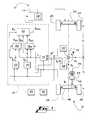
- FIG. 1is a schematic illustration of a vehicle including an active rear steering system, according to an exemplary embodiment.
- FIG. 2is a flow chart illustrating a method of a software module of the active rear steering system of FIG. 1 .
- FIG. 3is a flow chart illustrating a method of a software module of the active rear steering system of FIG. 1 .
- a vehicle 12includes an active rear steering (ARS) control system 10 , a steering wheel 44 , a steering column 46 , a front axle 48 , front wheels 26 , a rear axle 50 , and rear wheels 24 .
- the ARS control system 10includes an ARS controller 19 , a processor 40 , a memory 42 , and an ARS actuator 14 .
- the term “controller”refers to a computing device, such as but not limited to a programmable logic controller (PLC), remote terminal unit (RTU), or distributed control system (DCS), that monitors and affects the operational conditions of a given system.
- PLCprogrammable logic controller
- RTUremote terminal unit
- DCSdistributed control system
- the ARS controller 19includes software modules 16 , 18 a , 18 b , 20 , 22 , 23 that include instructions that are executable by the processor 40 .
- the illustrated ARS actuator 14includes a motor 28 that is configured to steer the rear wheels 24 of the vehicle 12 according to a rear steering command ⁇ rcom .
- the ARS control system 10includes a yaw rate sensor 30 configured to measure the yaw rate ⁇ ′ of the vehicle 12 , a speed sensor 32 configured to measure the longitudinal speed V x and lateral speed V y of the vehicle 12 , and a steering angle sensor 34 configured to measure the front steering angle ⁇ f of the vehicle 12 .
- the state software module 16is configured to determine the state S of the vehicle 12 as a function of the yaw rate ⁇ ′, the vehicle speed V x , and the front steering angle ⁇ f .
- Steering angle software modules 20 , 22are configured to determine rear steering angles ⁇ r1 , ⁇ r2 as a function of the yaw rate ⁇ ′ and the front steering angle ⁇ f .
- Shaping software modules 18 a , 18 bare configured to determine shaping functions F sh1 , F sh2 as a function of the front steering angle ⁇ f , the vehicle state S, and a respective one of the rear steering angles ⁇ r1 , ⁇ r2 .
- the combining software module 23is configured to combine the rear steering angles ⁇ r1 , ⁇ r2 with the shaping functions F sh1 , F sh2 to generate the rear steering command ⁇ rcom .
- the ARS actuator 14is configured to steer and control the rear wheels 24 as a function of the rear steering command ⁇ rcom . For example, the ARS actuator 14 generates a signal to drive the motor 28 using the rear steering command ⁇ rcom .
- the software modules 16 , 18 a , 18 b , 20 , 22 , 23are now described in further detail.
- the state software module 16is configured to determine the vehicle state S.
- various states Sare defined as follows.
- a first state S 1includes low speed V x and steady operation;
- a second state S 2includes high speed V x and steady operation;
- a third state S 3includes low speed V x and transient operation;
- a fourth state S 4includes high speed V x and transient operation.
- Steady operation and transient operationare defined for purposes of teaching by a front steering velocity threshold ⁇ fth ′, a minimum front steering velocity ⁇ fthmin ′, a yaw acceleration threshold ⁇ th ′′, and a minimum yaw acceleration ⁇ thmin ′′.
- operation above both of the thresholds ⁇ fth ′, ⁇ th ′′is transient operation and operation below one or both thresholds ⁇ fth ′, ⁇ th ′′ is steady operation.
- the minimums ⁇ fthmin ′, ⁇ thmin ′′are smaller than the thresholds ⁇ fth ′, ⁇ th ′′ and are used to verify steady state over a time period or number of cycles.
- the thresholds ⁇ fth ′, ⁇ th ′′are and the minimums ⁇ fthmin ′, ⁇ thmin ′′ are experimentally determined via testing vehicle 12 .
- high speed and low speedare defined by a threshold speed V th .
- Above the threshold speed V this high speed and below the threshold speed V th is low speed.
- the threshold speed V this 16 m/s.
- the state software module 16calculates the derivative of the front steering angle ⁇ f and the yaw rate ⁇ ′ to get a front steering velocity ⁇ f ′ and a yaw acceleration ⁇ ′′.
- the state software module 16determines whether the steering angle velocity ⁇ f ′ is greater than the steering angle velocity threshold ⁇ fth ′. If yes, the state software module 16 sets a first flag G 1 to one at box 150 .
- the state software module 16determines whether the steering angle velocity ⁇ f ′ is less than the minimum steering angle velocity ⁇ fthmin ′ for a certain amount of time (for example, 20 cycles with control cycle time of 10 msec, i.e. 200 msec). If yes, the state software module 16 sets the first flag G 1 to zero at box 152 . If not, the state software module 16 sets the first flag G 1 to one at box 150 .
- the state software module 16determines whether the yaw acceleration ⁇ ′′ is greater than the threshold yaw acceleration ⁇ th ′′. If yes, then the state software module 16 sets a second flag G 2 to one at box 146 . If no, at a step 140 , the state software module 16 determines whether the yaw acceleration ⁇ ′′ is less than the minimum yaw acceleration ⁇ thmin ′′ for a certain amount of time (for example, 20 cycles with control cycle time of 10 msec, i.e. 200 msec). If yes, then the state software module 16 sets the second flag G 2 to zero at box 148 . If no, the state software module 16 sets the second flag G 2 to one at box 146 . At a step 160 , the state software module 16 determines a variable flag G by multiplying the first flag G 1 and the second flag G 2 . Here, a variable flag G equal to one represents transient operation and a variable flag G equal to zero represents steady operation.
- the state software module 16determines whether the vehicle speed V x is less than the threshold speed V th . If yes, at a step 162 , the state software module 16 determines if the variable flag G is set to one. If no, the state software module 16 sets the vehicle state S to the first state S 1 at a box 166 . If yes, the state software module 16 sets the vehicle state S to the third state S 3 at a box 164 . If vehicle speed V x is not less than the threshold speed V th at step 161 , at a step 168 , the state software module 16 determines if the variable flag G is set to one. If no, the state software module 16 sets the vehicle state S to the second state S 2 at box 170 . If yes, the state software module 16 sets the vehicle state S to the fourth state S 4 at box 169 .
- the methodincludes alternative or additional vehicle states.
- the statecan alternatively be represented by a continuous signal where the magnitude of the signal relative to a threshold indicates the state.
- Exemplary steering angle software modules 20 , 22that are configured to determine the rear steering angles ⁇ r1 , ⁇ r2 are now described in further detail.
- a two degree-of-freedom model of yaw-plane dynamicsis used. While the vehicle 12 is undergoing handling maneuvers, it not only incurs a yaw motion, but it also experiences a side-slip motion at the same time.
- the yaw motionis partially characterized by the yaw rate ⁇ ′ and the lateral motion is partially characterized by the side slip or lateral velocity V y .
- the vehicle yaw-plane dynamicsare described by a second-order state equation:
- [ V y ′ ⁇ ′′ ][ - ( C f + C r ) m ⁇ ⁇ V x b ( C r - aC f m ⁇ ⁇ V x - V x bC r - aC f IV x - a 2 ⁇ C f + b 2 ⁇ C r IV x ] ⁇ [ V y ⁇ ′ ] + [ C f m C r m aC f I - bC r I ] ⁇ [ ⁇ f ⁇ r ]
- ais the distance from the center of gravity 52 of the vehicle 12 to the front axle 48 ;
- bis the distance from the center of gravity 52 of the vehicle 12 to the rear axle 50 ;
- C fis the cornering stiffness of both front wheels 26 of the front axle 48 ;
- C ris the cornering stiffness of both rear wheels 24 of the rear axle 50 ;
- Iis the moment of
- the rear steering angle ⁇ rcan be determined as a function of the front steering angle ⁇ f and yaw rate ⁇ ′ by setting both the lateral velocity V y and its derivative V y ′ to zero in the state equation to give:
- ⁇ r- C f C r ⁇ ⁇ f + 1 C r ⁇ ( aC f - bC r - m ⁇ ⁇ V x 2 V x ) ⁇ ⁇ ′
- the rear steering angle ⁇ ris the sum of the first rear steering angle ⁇ r1 and the second rear steering angle ⁇ r2 .
- the first rear steering angle ⁇ r1is a function of the front steering angle ⁇ f and is given by:
- the second rear steering angle ⁇ r2 signalis a function of the yaw rate ⁇ ′ and the longitudinal speed V x and is given by:
- ⁇ r ⁇ ⁇ 21 C r ⁇ ( aC f - bC r - m ⁇ ⁇ V x 2 V x ) ⁇ ⁇ ′ .
- the rear steering angles ⁇ r1 , ⁇ r2are determined based on different objectives such as subjective vehicle agility, vehicle turn circle reduction, or vehicle steering sensitivity modification as is understood by those familiar in the art.
- the shaping software modules 18 a , 18 bare configured to determine shaping functions F sh1 , F sh2 . Referring to FIG. 3 , an exemplary method of determining the first shaping function F sh1 with the shaping software module 18 a is now described.
- the shaping software module 18 adetermines if the first rear steering angle ⁇ r1 is less than a rear steering angle threshold ⁇ rthmin . If yes, the shaping software module 18 a sets the first shaping function F sh1 to a first shaping gain K sh ( 1 ) at box 184 .
- the shaping software module 18 adetermines if the state S is the third state S 3 or the fourth state S 4 . If yes, the shaping software module 18 a sets the first shaping function F sh1 to a second shaping gain K sh ( 2 ) at box 188 . If the state S is not third state S 3 or fourth state S 4 at step 186 , at a step 190 , the shaping software module 18 a determines if the state S is the first state S 1 .
- the shaping software module 18 asets the first shaping function F sh1 to a third shaping gain K sh ( 3 ) at box 192 . If the state S is not one at step 190 , the shaping software module 18 a sets the first shaping function F sh1 to a fourth shaping gain K sh ( 4 ) at box 194 .
- the shaping software module 18 bdetermines the second shaping function F sh2 according to the same method.
- the exemplary method of selecting a shaping gain K sh for the first shaping function F sh1takes into account the vehicle state S and a rear steering angle ⁇ r1 , ⁇ r2 .
- the exemplary shaping gains K share given by
- K sh ⁇ ( index )e Z ⁇ ( index ) ⁇ ⁇
- Z ⁇ ( index )Z 1 ⁇ ( index ) * Z 2 ⁇ ( index )
- Tis the loop time (for example, 10 msec)
- Nis loop number
- N this total number of loops
- ⁇ fthis front steering angle threshold (for example, 5 degrees)
- a and K sh(rate)are experimental values that are experimentally determined via vehicle testing.
- A(index)is [1 1 0.01 0.02]
- K sh(rate)is [0 0 ⁇ 5 ⁇ 10].
- the loop number Nis reset to zero when the front steering angle ⁇ f is less than the front steering angle threshold ⁇ fth .
- Other suitable values for the shaping gains K shcan also be used, the shaping functions F sh can be selected according to alternative methods, and the specific implementation of the shaping functions F sh to determine the rear steering command ⁇ rcom can be modified according to alternate embodiments.
- the sensors 30 , 32 , 34measure the yaw rate ⁇ ′′, vehicle speed V x , V y , and front steering angle ⁇ f .
- the ARS controller 19determines the rear steering command ⁇ rcom as described above.
- the state software module 16determines the vehicle state S
- the steering angle software modules 20 , 22determine rear steering angles ⁇ r1 , ⁇ r2
- the shaping software module 18 adetermine shaping functions F sh1 , F sh2
- the combining software module 23determines the rear steering command ⁇ rcom .
- the ARS actuator 14controls the motor 28 to steer the rear wheels 24 according to the rear steering command ⁇ rcom .
Landscapes
- Engineering & Computer Science (AREA)
- Physics & Mathematics (AREA)
- Mathematical Physics (AREA)
- Chemical & Material Sciences (AREA)
- Combustion & Propulsion (AREA)
- Transportation (AREA)
- Mechanical Engineering (AREA)
- Theoretical Computer Science (AREA)
- Steering Control In Accordance With Driving Conditions (AREA)
Abstract
Description
where a is the distance from the center of
Solving for the rear steering angle δrgives:
The second rear steering angle δr2signal is a function of the yaw rate ψ′ and the longitudinal speed Vxand is given by:
δrcom=Fsh1*δr1+Fsh2*δr2.
Claims (16)
Priority Applications (3)
| Application Number | Priority Date | Filing Date | Title |
|---|---|---|---|
| US12/702,652US8494719B2 (en) | 2009-02-12 | 2010-02-09 | Method and apparatus for controlling active rear steering |
| DE102010007615.5ADE102010007615B4 (en) | 2009-02-12 | 2010-02-11 | Active rear wheel steering control system and active rear wheel steering control system controller |
| CN 201010149414CN101934816B (en) | 2009-02-12 | 2010-02-12 | Active rear wheel steering control system and apparatus |
Applications Claiming Priority (2)
| Application Number | Priority Date | Filing Date | Title |
|---|---|---|---|
| US15194609P | 2009-02-12 | 2009-02-12 | |
| US12/702,652US8494719B2 (en) | 2009-02-12 | 2010-02-09 | Method and apparatus for controlling active rear steering |
Publications (2)
| Publication Number | Publication Date |
|---|---|
| US20120065842A1 US20120065842A1 (en) | 2012-03-15 |
| US8494719B2true US8494719B2 (en) | 2013-07-23 |
Family
ID=42664235
Family Applications (1)
| Application Number | Title | Priority Date | Filing Date |
|---|---|---|---|
| US12/702,652Expired - Fee RelatedUS8494719B2 (en) | 2009-02-12 | 2010-02-09 | Method and apparatus for controlling active rear steering |
Country Status (3)
| Country | Link |
|---|---|
| US (1) | US8494719B2 (en) |
| CN (1) | CN101934816B (en) |
| DE (1) | DE102010007615B4 (en) |
Families Citing this family (13)
| Publication number | Priority date | Publication date | Assignee | Title |
|---|---|---|---|---|
| EP2657106B1 (en)* | 2010-12-20 | 2015-08-26 | Toyota Jidosha Kabushiki Kaisha | Vehicular steering control device |
| FR3028828B1 (en)* | 2014-11-26 | 2016-12-23 | Jtekt Europe Sas | SELF-ADJUSTING AND SURROUNDING DETECTOR FOR MOTOR VEHICLE |
| KR102489196B1 (en) | 2015-08-14 | 2023-01-17 | 크라운 이큅먼트 코포레이션 | Model-based diagnosis based on steering model |
| CN107921964B (en) | 2015-08-14 | 2020-09-08 | 克朗设备公司 | Diagnostic oversight procedure to determine if a traction system is in a faulty condition |
| AU2017393176B2 (en) | 2017-01-13 | 2023-05-11 | Crown Equipment Corporation | High speed straight ahead tiller desensitization |
| EP3568374B1 (en) | 2017-01-13 | 2023-05-10 | Crown Equipment Corporation | Traction speed recovery based on steer wheel dynamic |
| US11623686B1 (en)* | 2019-12-10 | 2023-04-11 | Zoox, Inc. | Determining bias of vehicle axles |
| US11345400B2 (en)* | 2020-06-30 | 2022-05-31 | Zoox, Inc. | Trajectory tracking with four-wheel steering and steering limits |
| US11414127B2 (en) | 2020-06-30 | 2022-08-16 | Zoox, Inc. | Trajectory tracking with four-wheel steering |
| US11518412B2 (en) | 2020-06-30 | 2022-12-06 | Zoox, Inc. | Trajectory determination for four-wheel steering |
| CN112046607B (en)* | 2020-09-11 | 2021-11-02 | 中国第一汽车股份有限公司 | Yaw adjusting method and device in vehicle driving, vehicle and medium |
| KR20230028973A (en)* | 2021-08-23 | 2023-03-03 | 현대모비스 주식회사 | Apparatus and method for four wheel steering control |
| US20250304156A1 (en)* | 2024-03-26 | 2025-10-02 | Honda Motor Co., Ltd. | Systems and methods for controlling vehicle travel |
Citations (12)
| Publication number | Priority date | Publication date | Assignee | Title |
|---|---|---|---|---|
| US4679808A (en)* | 1985-03-15 | 1987-07-14 | Nissan Motor Co., Ltd. | Vehicle motion estimating system |
| US4720790A (en)* | 1984-05-21 | 1988-01-19 | Kabushiki Kaisha Toyota Chuo Kenkyusho | Apparatus for controlling steer angle of rear wheels of vehicle |
| US5020619A (en)* | 1989-01-18 | 1991-06-04 | Mazda Motor Corporation | Rear wheel steering device for a vehicle |
| EP0477820A2 (en) | 1990-09-25 | 1992-04-01 | Mazda Motor Corporation | Steering device for the rear wheels |
| DE4332040A1 (en) | 1992-09-24 | 1994-03-31 | Mazda Motor | Four-wheel steering system for road vehicle - has target value for control of steering of rear wheels in answer to steering movement of front wheels by addition and subtraction of operands determined by basic position of signals |
| US5457632A (en)* | 1993-01-19 | 1995-10-10 | Toyota Jidosha Kabushiki Kaisha | Vehicle steering control system wherein steering angle change is limited to within a predetermined range upon occurrence of abnormality in detected vehicle yaw rate |
| US5606502A (en)* | 1993-12-27 | 1997-02-25 | Nissan Motor Co., Ltd. | Steering angle control system for vehicle |
| US6122577A (en)* | 1996-09-07 | 2000-09-19 | Robert Bosch Gmbh | Device and method to monitor sensors in vehicles |
| US6580988B2 (en)* | 2001-11-06 | 2003-06-17 | General Motors Corporation | Rear wheel steering control |
| US20090048735A1 (en)* | 2005-12-23 | 2009-02-19 | Renault S.A.S. | Method and device for controlling turning angle of a motor vehicle rear wheel |
| US7540351B2 (en)* | 2005-07-19 | 2009-06-02 | Denso Corporation | Steering control system |
| EP2085293A1 (en) | 2006-10-20 | 2009-08-05 | Honda Motor Co., Ltd | Vehicle rear wheel steered angle controller |
Family Cites Families (3)
| Publication number | Priority date | Publication date | Assignee | Title |
|---|---|---|---|---|
| DE3819849A1 (en)* | 1988-06-10 | 1989-12-14 | Siemens Ag | PROCESS CONTROLLED ACTIVE REAR AXLE KINEMATICS OF A VEHICLE |
| EP0601588B1 (en)* | 1992-12-10 | 1997-06-11 | Mazda Motor Corporation | Four-wheel steering system for vehicle |
| US7130729B2 (en)* | 2004-07-26 | 2006-10-31 | General Motors Corporation | Adaptive compensation of rear-wheel steering control using vehicle dynamics parameter estimation |
- 2010
- 2010-02-09USUS12/702,652patent/US8494719B2/ennot_activeExpired - Fee Related
- 2010-02-11DEDE102010007615.5Apatent/DE102010007615B4/ennot_activeExpired - Fee Related
- 2010-02-12CNCN 201010149414patent/CN101934816B/ennot_activeExpired - Fee Related
Patent Citations (12)
| Publication number | Priority date | Publication date | Assignee | Title |
|---|---|---|---|---|
| US4720790A (en)* | 1984-05-21 | 1988-01-19 | Kabushiki Kaisha Toyota Chuo Kenkyusho | Apparatus for controlling steer angle of rear wheels of vehicle |
| US4679808A (en)* | 1985-03-15 | 1987-07-14 | Nissan Motor Co., Ltd. | Vehicle motion estimating system |
| US5020619A (en)* | 1989-01-18 | 1991-06-04 | Mazda Motor Corporation | Rear wheel steering device for a vehicle |
| EP0477820A2 (en) | 1990-09-25 | 1992-04-01 | Mazda Motor Corporation | Steering device for the rear wheels |
| DE4332040A1 (en) | 1992-09-24 | 1994-03-31 | Mazda Motor | Four-wheel steering system for road vehicle - has target value for control of steering of rear wheels in answer to steering movement of front wheels by addition and subtraction of operands determined by basic position of signals |
| US5457632A (en)* | 1993-01-19 | 1995-10-10 | Toyota Jidosha Kabushiki Kaisha | Vehicle steering control system wherein steering angle change is limited to within a predetermined range upon occurrence of abnormality in detected vehicle yaw rate |
| US5606502A (en)* | 1993-12-27 | 1997-02-25 | Nissan Motor Co., Ltd. | Steering angle control system for vehicle |
| US6122577A (en)* | 1996-09-07 | 2000-09-19 | Robert Bosch Gmbh | Device and method to monitor sensors in vehicles |
| US6580988B2 (en)* | 2001-11-06 | 2003-06-17 | General Motors Corporation | Rear wheel steering control |
| US7540351B2 (en)* | 2005-07-19 | 2009-06-02 | Denso Corporation | Steering control system |
| US20090048735A1 (en)* | 2005-12-23 | 2009-02-19 | Renault S.A.S. | Method and device for controlling turning angle of a motor vehicle rear wheel |
| EP2085293A1 (en) | 2006-10-20 | 2009-08-05 | Honda Motor Co., Ltd | Vehicle rear wheel steered angle controller |
Non-Patent Citations (2)
| Title |
|---|
| Ackermann et al., "Robust yaw damping of cars with front and rear wheel steering", IEEE Transactions on Control Systems Technology, vol. 1 No. 1, Mar. 1993, pp. 15-20.* |
| Matsumoto et al., "Vehicle lateral velocity and yaw rate control with two independent control inputs", American Control Conference, May 1990, pp. 1868-1875.* |
Also Published As
| Publication number | Publication date |
|---|---|
| CN101934816A (en) | 2011-01-05 |
| DE102010007615B4 (en) | 2015-06-25 |
| CN101934816B (en) | 2012-11-07 |
| DE102010007615A1 (en) | 2010-09-30 |
| US20120065842A1 (en) | 2012-03-15 |
Similar Documents
| Publication | Publication Date | Title |
|---|---|---|
| US8494719B2 (en) | Method and apparatus for controlling active rear steering | |
| US6804594B1 (en) | Active steering for handling/stability enhancement | |
| US8571758B2 (en) | Continuous correction for steering wheel angle offset | |
| US20060235589A1 (en) | Adaptive rear-wheel steer open-loop control for vehicle-trailer system | |
| US7308351B2 (en) | Method for coordinating a vehicle dynamics control system with an active normal force adjustment system | |
| US6909957B2 (en) | Method for controlling yaw and transversal dynamics in a road vehicle | |
| CN101417654B (en) | System for estimating vehicle states for rollover prevention | |
| US8670905B2 (en) | Vehicle stability control method and system | |
| US20080015754A1 (en) | System for estimating and compensating for lateral disturbances using controlled steering and braking | |
| EP1386807B1 (en) | System and method for determining a wheel departure angle for a rollover control system | |
| US12269348B2 (en) | Apparatus for controlling autonomous driving of independent driving electric vehicle and method thereof | |
| US7099759B2 (en) | Method and apparatus for estimating steering behavior for integrated chassis control | |
| US9026334B2 (en) | Vehicle attitude control system | |
| US9505286B2 (en) | Method and device for preventing the lateral rollover of motor vehicle | |
| EP2203340A2 (en) | Vehicle body speed estimating device | |
| JP2007216942A (en) | Side slip angle estimation device, automobile, and side slip angle estimation method | |
| Soudbakhsh et al. | A collision avoidance steering controller using linear quadratic regulator | |
| Ding et al. | A gain-scheduled PID controller for automatic path following of a tractor semi-trailer | |
| US11685434B2 (en) | Method for rear steering control of a vehicle | |
| WO2010046166A1 (en) | Driving dynamics controller with slip-angle-based steering intervention | |
| US20120035784A1 (en) | Method for stabilizing a vehicle having an integrated rollover prevention function | |
| CN117465429A (en) | Lane correction method and device for vehicle, computer equipment and medium | |
| US7788006B2 (en) | Rollover stability system including allowance for the steering angle | |
| Lin et al. | High speed optimal yaw stability of tractor-semitrailers with active trailer steering | |
| JP5326562B2 (en) | Turning behavior detection device, turning behavior detection method, and yaw rate estimation method |
Legal Events
| Date | Code | Title | Description |
|---|---|---|---|
| AS | Assignment | Owner name:GM GLOBAL TECHNOLOGY OPERATIONS, INC., MICHIGAN Free format text:ASSIGNMENT OF ASSIGNORS INTEREST;ASSIGNORS:GHONEIM, YOUSSEF A.;O'DEA, KEVIN A.;ARGALAS, EDWARD J.;SIGNING DATES FROM 20091111 TO 20100413;REEL/FRAME:024564/0241 | |
| AS | Assignment | Owner name:GM GLOBAL TECHNOLOGY OPERATIONS, INC., MICHIGAN Free format text:ASSIGNMENT OF ASSIGNORS INTEREST;ASSIGNORS:GHONEIM, YOUSSEF A.;FELLER, ROSS;O'DEA, KEVIN A.;AND OTHERS;SIGNING DATES FROM 20091111 TO 20100907;REEL/FRAME:024997/0673 | |
| AS | Assignment | Owner name:WILMINGTON TRUST COMPANY, DELAWARE Free format text:SECURITY AGREEMENT;ASSIGNOR:GM GLOBAL TECHNOLOGY OPERATIONS, INC.;REEL/FRAME:025327/0156 Effective date:20101027 | |
| AS | Assignment | Owner name:GM GLOBAL TECHNOLOGY OPERATIONS LLC, MICHIGAN Free format text:CHANGE OF NAME;ASSIGNOR:GM GLOBAL TECHNOLOGY OPERATIONS, INC.;REEL/FRAME:025781/0333 Effective date:20101202 | |
| FEPP | Fee payment procedure | Free format text:PAYOR NUMBER ASSIGNED (ORIGINAL EVENT CODE: ASPN); ENTITY STATUS OF PATENT OWNER: LARGE ENTITY | |
| STCF | Information on status: patent grant | Free format text:PATENTED CASE | |
| AS | Assignment | Owner name:GM GLOBAL TECHNOLOGY OPERATIONS LLC, MICHIGAN Free format text:RELEASE BY SECURED PARTY;ASSIGNOR:WILMINGTON TRUST COMPANY;REEL/FRAME:034287/0001 Effective date:20141017 | |
| FPAY | Fee payment | Year of fee payment:4 | |
| FEPP | Fee payment procedure | Free format text:MAINTENANCE FEE REMINDER MAILED (ORIGINAL EVENT CODE: REM.); ENTITY STATUS OF PATENT OWNER: LARGE ENTITY | |
| LAPS | Lapse for failure to pay maintenance fees | Free format text:PATENT EXPIRED FOR FAILURE TO PAY MAINTENANCE FEES (ORIGINAL EVENT CODE: EXP.); ENTITY STATUS OF PATENT OWNER: LARGE ENTITY | |
| STCH | Information on status: patent discontinuation | Free format text:PATENT EXPIRED DUE TO NONPAYMENT OF MAINTENANCE FEES UNDER 37 CFR 1.362 | |
| FP | Lapsed due to failure to pay maintenance fee | Effective date:20210723 |