US8494686B2 - Electrical energy usage monitoring system - Google Patents
Electrical energy usage monitoring systemDownload PDFInfo
- Publication number
- US8494686B2 US8494686B2US12/251,449US25144908AUS8494686B2US 8494686 B2US8494686 B2US 8494686B2US 25144908 AUS25144908 AUS 25144908AUS 8494686 B2US8494686 B2US 8494686B2
- Authority
- US
- United States
- Prior art keywords
- data
- electrical
- management
- node
- interface
- Prior art date
- Legal status (The legal status is an assumption and is not a legal conclusion. Google has not performed a legal analysis and makes no representation as to the accuracy of the status listed.)
- Expired - Fee Related, expires
Links
Images


Classifications
- G—PHYSICS
- G05—CONTROLLING; REGULATING
- G05B—CONTROL OR REGULATING SYSTEMS IN GENERAL; FUNCTIONAL ELEMENTS OF SUCH SYSTEMS; MONITORING OR TESTING ARRANGEMENTS FOR SUCH SYSTEMS OR ELEMENTS
- G05B15/00—Systems controlled by a computer
- G05B15/02—Systems controlled by a computer electric
- G—PHYSICS
- G06—COMPUTING OR CALCULATING; COUNTING
- G06F—ELECTRIC DIGITAL DATA PROCESSING
- G06F1/00—Details not covered by groups G06F3/00 - G06F13/00 and G06F21/00
- G06F1/26—Power supply means, e.g. regulation thereof
- G—PHYSICS
- G06—COMPUTING OR CALCULATING; COUNTING
- G06F—ELECTRIC DIGITAL DATA PROCESSING
- G06F1/00—Details not covered by groups G06F3/00 - G06F13/00 and G06F21/00
- G06F1/26—Power supply means, e.g. regulation thereof
- G06F1/266—Arrangements to supply power to external peripherals either directly from the computer or under computer control, e.g. supply of power through the communication port, computer controlled power-strips
- H—ELECTRICITY
- H02—GENERATION; CONVERSION OR DISTRIBUTION OF ELECTRIC POWER
- H02J—CIRCUIT ARRANGEMENTS OR SYSTEMS FOR SUPPLYING OR DISTRIBUTING ELECTRIC POWER; SYSTEMS FOR STORING ELECTRIC ENERGY
- H02J2310/00—The network for supplying or distributing electric power characterised by its spatial reach or by the load
- H02J2310/10—The network having a local or delimited stationary reach
- H02J2310/12—The local stationary network supplying a household or a building
- H02J2310/16—The load or loads being an Information and Communication Technology [ICT] facility
- Y—GENERAL TAGGING OF NEW TECHNOLOGICAL DEVELOPMENTS; GENERAL TAGGING OF CROSS-SECTIONAL TECHNOLOGIES SPANNING OVER SEVERAL SECTIONS OF THE IPC; TECHNICAL SUBJECTS COVERED BY FORMER USPC CROSS-REFERENCE ART COLLECTIONS [XRACs] AND DIGESTS
- Y02—TECHNOLOGIES OR APPLICATIONS FOR MITIGATION OR ADAPTATION AGAINST CLIMATE CHANGE
- Y02A—TECHNOLOGIES FOR ADAPTATION TO CLIMATE CHANGE
- Y02A30/00—Adapting or protecting infrastructure or their operation
- Y02A30/60—Planning or developing urban green infrastructure
- Y—GENERAL TAGGING OF NEW TECHNOLOGICAL DEVELOPMENTS; GENERAL TAGGING OF CROSS-SECTIONAL TECHNOLOGIES SPANNING OVER SEVERAL SECTIONS OF THE IPC; TECHNICAL SUBJECTS COVERED BY FORMER USPC CROSS-REFERENCE ART COLLECTIONS [XRACs] AND DIGESTS
- Y02—TECHNOLOGIES OR APPLICATIONS FOR MITIGATION OR ADAPTATION AGAINST CLIMATE CHANGE
- Y02B—CLIMATE CHANGE MITIGATION TECHNOLOGIES RELATED TO BUILDINGS, e.g. HOUSING, HOUSE APPLIANCES OR RELATED END-USER APPLICATIONS
- Y02B90/00—Enabling technologies or technologies with a potential or indirect contribution to GHG emissions mitigation
- Y02B90/20—Smart grids as enabling technology in buildings sector
- Y—GENERAL TAGGING OF NEW TECHNOLOGICAL DEVELOPMENTS; GENERAL TAGGING OF CROSS-SECTIONAL TECHNOLOGIES SPANNING OVER SEVERAL SECTIONS OF THE IPC; TECHNICAL SUBJECTS COVERED BY FORMER USPC CROSS-REFERENCE ART COLLECTIONS [XRACs] AND DIGESTS
- Y04—INFORMATION OR COMMUNICATION TECHNOLOGIES HAVING AN IMPACT ON OTHER TECHNOLOGY AREAS
- Y04S—SYSTEMS INTEGRATING TECHNOLOGIES RELATED TO POWER NETWORK OPERATION, COMMUNICATION OR INFORMATION TECHNOLOGIES FOR IMPROVING THE ELECTRICAL POWER GENERATION, TRANSMISSION, DISTRIBUTION, MANAGEMENT OR USAGE, i.e. SMART GRIDS
- Y04S20/00—Management or operation of end-user stationary applications or the last stages of power distribution; Controlling, monitoring or operating thereof
Definitions
- the present inventionis directed to an apparatus, system and method for measuring real-time electrical energy usage at a private residence, commercial property, or other facility which is electrically connected to one or more external power sources, such as a power grid, and not only monitoring gross electrical energy usage, but allowing for the granular monitoring of the constituent load endpoints constituting aggregate usage.
- the present inventionis further directed to a method for the management, processing, display and remediation of electrical energy usage.
- Fostering consumer participation in efficient utility usage and enabling consumers to shop more intelligently for utility servicesrequires they have easy access to a comprehensive set of easily understood and digested usage and billing data. For such a system to be most effective, it needs to examine not only gross consumption, but allow for granular visibility into usage across a users entire electrical system, additionally, it must succeed in presenting this data in a manner that provides, visibility, education and the ability to pro-actively remediate usage, both automatically and through an intuitive interface.
- a system of this typemight include services such as the presentation of real-time and historical cost and usage statistics, cost/trend analysis, the ability to propose or automatically implement optimizations to electrical usage profiles, recommend optimal electrical device/appliance/fixture retrofitment, facilitate consumers tailoring their participation in dynamic pricing options made available by utility providers, present comparative data in a standardized format (such as the Nutritional Facts standard implemented on food stuffs) allowing consumers to shop more intelligently by directly comparing cost analysis as well as quality of service and other data between utility providers, and much more. Additionally, an optimal implementation would provide a portal through which a consumer community could develop and share information and knowledge, further engaging and educating users.
- the present inventionis an apparatus, system and method consisting of one or more networked modular electrical energy sensors (Nodes) integrated into the standard form factor of common electrical interfaces, such as electrical circuit breakers and wall outlets and replacing those interfaces in an residential or business electrical system.
- Nodesnetworked modular electrical energy sensors
- the described Nodesmonitoring electrical usage and state, including current, voltage, volt amps, power, phase, line noise and power factor, additionally being capable of controlling the state of the interface, such as breaking, reinstating or cycling the electrical connection to an attached load.
- Electrical usage and state data collected by the Nodeis communicated to a management and display console (Console) for processing, management and display.
- Consolemanagement and display console
- the Consolebeing an electronic computer capable communicating with Nodes and other connected resources or systems, processing and persisting data for display, and presenting user, and other common input/output interfaces for interacting with the system.
- Installed on the Console systemis software (Software) for performing the processing, management and display of electrical energy usage and state data, also allowing users to control or manipulate said data and the Nodes, Consoles and other associated resources networked to the management and display console.
- the Softwarefurther providing a user interface for programming the system and interacting with collected data; facilitating the presentation of real-time and historical cost and usage statistics, both visually, such as through a floor plan view of cost and usage across the monitored electrical systems circuits/rooms/outlets/fixtures/appliance or cost/usage reports or projections generated for review.
- the type of information gleanedmay include simple data such as a color indicator of the state of electrical energy usage for a site, or more detailed processing such as cost and usage statistics, cost/trend analysis, usage and cost forecasting, the ability to propose or automatically implement optimizations to electrical usage profiles, recommendation of optimal electrical device/appliance/fixture retrofitment, fostering consumers tailoring their participation in dynamic pricing options made available by utility providers, providing visibility into “what if” usage and cost scenarios/forecasts, presenting comparative utility provider data in a standardized format (such as the Nutritional Facts standard implemented on food stuffs) allowing consumers to shop more intelligently by directly comparing cost analysis as well as quality of service and other data between providers, and the presentation of any other metrics derivable from the data points collected by the Nodes.
- simple datasuch as a color indicator of the state of electrical energy usage for a site
- more detailed processingsuch as cost and usage statistics, cost/trend analysis, usage and cost forecasting, the ability to propose or automatically implement optimizations to electrical usage profiles, recommendation of optimal electrical device/appli
- the Node sensor circuitdetects and measures the electrical energy usage characteristics of any attached load(s), including Power, Voltage, Amperage, Phase, Power Factor, Volt-Amps, line frequency, and noise.
- the Node processing circuitinterprets and carries out instructions provided by the embedded software. It tests and manipulates data, and transfers information to and from other components within the sensing/detecting node, such as the working memory, the communication interface, cutoff circuit, status indicators or management interface.
- the Node memory associated with the processing circuitis used as a temporary store of data that may be changed, deleted, or otherwise manipulated.
- the Node load controller circuitprovides a means to electrically connect and disconnect, as well as vary the duty cycle of, the attached load.
- the Node communication controller and interface circuitsprovide the means of sending data from the Node to the other system components, and to receive data from the other system components.
- the Node power supply circuitsupplies the Node's circuitry with the necessary operational electrical power.
- the Softwareis the associated set of programmatic instructions for the management and processing of the electrical energy usage data collected by the system: the display of said data, the collection of user input, the issuance of remediation and control commands and communications to and from other system components and remote services as well as communication with extracurricular assets.
- the Management and Display Console hardwareprovides the physical means for running the Software, displaying the Software output through associated displays and indicators, collecting user input via common user input devices and methods, and communications interfaces for exchanging data with system components and with associated TCP/IP networks.
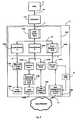
- FIG. 1is a block diagram representing the component ensemble constituting the energy sensing/detecting nodes responsible for both monitoring and reporting electrical energy usage/consumption data as well as implementing remote control mechanisms of the proposed system.
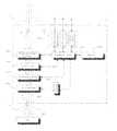
- FIG. 2is a block diagram of the preferred embodiment implemented on a preferred type electrical system and hardware; shown are multiple instances of the proposed technology installed at a multitude of possible electrical energy monitoring endpoints in the electrical system, and including the presence of a data processing, management and display console with the Software installed.
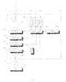
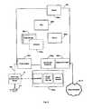
- FIG. 3is a block diagram representing the intercommunication between disparate components of the preferred embodiment when implemented on a preferred type electrical system and hardware; the amalgamated sensing/detecting nodes and their associated management and display console constituting the proposed invention.
- FIG. 4is a block diagram representing a high level view of the major software components or modules comprising the proposed software system (Software) in its preferred embodiment.
- FIG. 5is a block diagram defining the major hardware components comprising the preferred embodiment of the Console apparatus of the proposed invention.
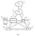
- FIG. 6is a block diagram of a typical personal type electronic computer system (PC) with the proposed Software installed additionally including a device for bridging communications between said Software and the communication medium native to the Node and Console systems proposed by the invention in its preferred embodiment and implemented in an typical residential or commercial electrical system environment.
- PCpersonal type electronic computer system
- the following detailed descriptionpresents an embodiment of the invention providing an apparatus, system and method consisting of networked modular electrical energy sensing/detecting/controlling apparatus (Nodes), an data management and display system/appliance, and an data management, processing, display and control software (Software) to detect, process, manage, present and control both real-time and historic electrical energy usage data (metrics, statistics, etc), additionally allowing the intelligent management of energy usage through consumer education as well as both manual and automated usage controls.
- Nodesnetworked modular electrical energy sensing/detecting/controlling apparatus
- Softwaredata management, processing, display and control software
- Nodesare integrated into the standardized form-factor components typical of household and commercial electrical interfaces, such as circuit breakers, wall outlets, light switches, plug ends, power strips, etc, additionally allowing integration with appliances or other load devices and being capable of processing data;
- sensors and the associated management, processing and display systemsare capable of bidirectional communication over a multiplex of communication mediums.
- Section onewill provide a hardware level overview of the Node in its preferred embodiment.
- Section twowill describe the invention in its preferred embodiment implemented in an common electrical system environment.
- Section threewill be a description of the preferred embodiments management and display console appliance and associated software system for management, processing, presentation and remediation of electrical energy usage across several use cases.
- the Node system ( 300 )includes 6 principal components: 1. an sensing/detecting component ( 300 e ); 2. an processing component ( 300 c ); 3. an memory component ( 300 d ); 4. an load control circuit ( 300 g ); 5. an data communication component ( 300 b ); 6. an power supply component ( 300 f ); 7. an load control manual override component ( 300 h ) and 8. an management/communication interface ( 300 a )
- the sensor circuit ( 300 e )measures the electrical energy usage characteristics of any attached load ( 220 ), including power, current, voltage, phase, volt-amps, power factor, line frequency, and noise, and relays that data to the processing circuit ( 300 c ) for handling.
- the power supply circuit ( 300 f )draws power directly from the attached line ( 1 a ), to supply electrical power for the Node's ( 300 ) operations.
- the processing circuit ( 300 c )will monitor the power supply circuit ( 300 f ), in order to optionally include or exclude the electrical energy usage characteristics of the Node ( 300 ) itself from measurements.
- the Load control circuit ( 300 g )provides a means to disconnect or cycle the electrical power to the attached load ( 220 ).
- the load control circuit ( 300 g )receives instructions from the main processing circuit ( 300 c ), in response to instructions received via an communications interface ( 300 a,b ) or in response to an locally detected events or pre-programmed conditions.
- the load control circuit ( 300 f )includes a manual override switch ( 300 h ), so that this behavior may be optionally disabled by the user.
- the Communications Interface circuits ( 300 a,b )provides a means for sending and receiving data to and from any of the inventions discrete component system's such as, to send and receive data to and from an Node ( 300 ), to and from an Data Management and Display console ( FIG. 2 [ 150 ]) or an conglomerate of the inventions discrete component system's as well as any other device capable of communicating in a compatible protocol.
- the Communications circuits ( 300 a,b )may employ any of the optionally offered wired or wireless communications methods and associated interfaces, including IP (Ethernet) over power line ( 300 b ), 802.11 Wifi, Bluetooth, 802.15.4 (zigbee), Ethernet, Serial (USB, RS-232, etc), etc.
- the communications interface ( 300 e )may be described as a “Management” interface, for the purposes of direct communication with a personal computer for the initial set-up and configuration as well as ongoing management and maintenance of an Node.
- the processing circuit ( 300 c )is responsible for collecting, processing, and managing data including, but not limited to, the storage and retrieval of data in memory ( 300 d ), sending and receiving data via the communications interfaces ( 300 a,b ), managing/controlling the power supply ( 300 f ) and Load control ( 300 g ) circuits and interpreting and executing commands.
- FIGS. 2 through 3will provide a comprehensive view of the preferred embodiment implemented on a preferred type electrical system and hardware, but is not intended to limit the applicable environments.
- One of ordinary skill in the artwill recognize that the present invention can be implemented with the accompaniment of other electrical system configurations; Large facility/commercial electrical systems, ‘off grid’ or self contained electrical systems and fractional electrical systems that use a plurality of power sources are examples of such.
- One can appreciate that the present inventioncan also be practiced in combination with remote processing, data storage, and user interface, whether over a distributed network or via removable hardware or media directly interfacing the proposed hardware.
- poweris typically delivered to consumers by a utility service provider ( 10 ) via utility lines ( 10 a ) and the consumers electrical energy usage monitored by the utility supplied electricity meter ( 10 b ).
- the utility supplied electricity meter ( 10 b )feeds directly into distribution panel ( 200 ), in which an optional Main Circuit breaker ( 100 a ) and an multitude of distribution circuit breakers ( 100 *, 200 *) reside.
- the distribution circuit breakers ( 100 *, 200 *)then feed any number of electrical outlets ( 110 *, 210 *) throughout the electrical system ( 1 *), which in turn are connected to any number of load appliances ( 120 *, 220 *).
- a distribution circuit breaker ( 100 *, 200 *)may directly feed a load appliance ( 120 *, 220 *) such as a washing machine or water heater.
- the described systemprovides a means for installing a Node at any point along the electrical path between the load appliance ( 120 *, 220 *) and the electrical energy source (e.g. The Utility meter 10 b ), by way of packaging an Node into standardized form-factor electrical interfaces, such as an circuit breaker ( 100 b ), electrical outlet ( 100 a ), multi-plug adapter ( 10 b ), or within the load appliance itself ( 120 a ).
- Thiswill provide the end user with a multitude of options for measuring and controlling electrical energy usage across an entire electrical system ( 1 ) at a very granular level as well as in total.
- FIG. 3defines one of many possible arrangements and relative locations of the different Nodes ( 300 , 310 ), data management and display Consoles ( 150 ) and electronic Computer Systems ( 160 ) when implemented on a preferred type electrical system.
- Installed on both the Console ( 150 ) and the Computer System ( 160 )is the proposed Software, facilitating communication with the Nodes ( 300 , 310 ) other Consoles ( 150 ) and Computer Systems ( 160 ), alternatively, an Computer System ( 160 ) excluding the Software may still communicate with an Console ( 150 ) or other Software enabled Computer Systems ( 160 ); further, Consoles ( 150 ) and Computer Systems ( 160 ) are capable of communicating with resources decoupled from the local electrical system.
- each Node ( 300 , 310 ) and display console ( 150 , 160 )may communicate bi-directionally with any other Node ( 300 , 310 ) or Console ( 150 ), forming a ‘meshed’ communication network ( 45 ).
- a Node ( 300 )that is packaged inside a circuit breaker may use an IP over power Line interface to communicate over the home wiring ( FIG. 2-1 j ) with a Console ( 150 ).
- the display console ( 150 )may relay data via 802.11 Wifi to a second node ( 310 ) that is integrated directly into a load appliance.
- the Console ( 150 )includes optionally an wired or wireless Ethernet interface for connecting to the end user's Local Area Network (LAN) and/or Wireless Local Area network (WLAN) ( 50 ), facilitating communication with the end user's Computer System ( 160 ).
- LANLocal Area Network
- WLANWireless Local Area network
- an Ethernet to power line bridge ( 30 )may be employed to allow direct communications from the Computer System ( 160 ) to the Nodes and/or Console.
- the Data Management display consoleis connected to the Internet ( 51 ) via the end user's LAN or WLAN ( 50 ), allowing for data to be sent to/from remote locations.
- a Console ( 150 ) or Computer System ( 160 )may also include an Home Area Network (HAN) interface for communicating directly with the utility supplied electricity meter ( 10 b ).
- HANHome Area Network
- FIGS. 4 through 6a description of each section in the use case template that addresses the attached use cases UC1. See Appendix. Describing FIG. 4 will illustrate the components comprising the Software, FIG. 5 describing the data management and display console appliance (Console), FIG. 6 describing the proposed software (Software) implemented on a personal computer and the final section providing a description of each section in the use case template coupled with Use Case(s) UC. 1, which are used primarily to capture the high level user-functional requirements of one embodiment of the Console and the installed Software system component of the proposed invention.
- FIG. 4will illustrate the components comprising the Software, FIG. 5 describing the data management and display console appliance (Console), FIG. 6 describing the proposed software (Software) implemented on a personal computer and the final section providing a description of each section in the use case template coupled with Use Case(s) UC. 1, which are used primarily to capture the high level user-functional requirements of one embodiment of the Console and the installed Software system component of the proposed invention.
- FIG. 4there is represented a high level view of the major software components or modules comprising the proposed software system (Software) ( 400 ).
- Said Software ( 400 )being responsible for sending and receiving data between the local Software ( 400 ) instance and Nodes, Consoles, PC's running additional instances of the Software ( 400 ) and other resources residing on the local electrical system, the local area network or a wide area network such as the Internet, additionally being responsible for processing, managing, persisting and displaying data, as well as receiving and processing user input.
- Transport module ( 400 a )a system for communicating messages between resources such as Nodes and other Software instances, and the component modules of the local Software instance ( 400 ) and comprises an incoming connection component, a core logic component, and an outgoing connection component.
- the incoming connection componentreceives messages from a sending resource and wraps the messages as a generic object in a message object.
- the core logic componentis coupled to the incoming connection component and receives the message object from the incoming connection component.
- the outgoing connection componentis coupled to the core logic component and receives the message object from the core logic component, unwraps the message object to retrieve the message, prepares the message for delivery to a destination module such as the Authentication module ( 400 b ) or the data collection module ( 400 c ), and delivers the message to said module.
- a destination modulesuch as the Authentication module ( 400 b ) or the data collection module ( 400 c ), and delivers the message to said module.
- the incoming connection component, the core logic component, and the outgoing connection componenthave standardized interfaces and function together as an integrated unit.
- the security module ( 400 b )is responsible for authentication, authorization and cryptographic services.
- Component modules of the Software system ( 400 )request services from the security module ( 400 b ) such as authentication of a package received by the Transport module ( 400 a ) or authorization of a user or resource to manipulate data managed by the Software ( 400 ).
- the described modulemay be pluggable and is derived from common interfaces, protocols and standards, insuring flexibility, extensibility and interoperability across implementations.
- the data collection/compression module ( 400 c )is a multipurpose data compression module responsible for compressing data supplied by a Node or other resource of a collective network such as the local electrical system or the Internet in response to a request from an Console or other device with an instance or the Software ( 400 ) running, which consists in: providing a data compression module ( 400 c ), that is inclusive of a data collection component designed to receive data supplied by the Software ( 400 ), an Node or other resource and redirect it towards the compression component of the module, said collection component being also designed to receive data from the compression component and redirect it towards the consulting module.
- the methodfurther consists in: examining in the request an indication concerning decompression aptitude of the consulting module and performing in the compression component, on the data required by said request and supplied by the Software ( 400 ), Node, module ( 400 *) or other resource a compression adapted to the indications concerning decompression aptitude contained in the request.
- the data storage component ( 400 d )is a structure responsible for storing collected data and other information organized in such a way that the Software ( 400 ) or an component module ( 400 *) may quickly select desired sets of data.
- the real-time event engine ( 400 e )is responsible for managing a data stream from the data collection and compression module ( 400 c ) for real-time display, such that data is not stored post display. Additionally generating event alerts based on the analysis of said data, through both display and other event notification methods and an automated remediation system.
- Data processing components ( 400 f )are responsible for the majority of user driven data processing and comprise several logical components:
- the Profiling Engine ( 400 g )is responsible for analyzing data and identifying patterns per the set of decided-upon profiling variables, such as usage statistics for identifying a load appliance, or devices based on either known signatures or an AI driven by pre-programmed or learned patterns.
- the Report Generator ( 400 h )is responsible for facilitating the generation of generic reports whose data sets are defined by the Software ( 400 ) or custom reports.
- the composite data sets of the generated reportsare variable and can be defined, for instance, as user or system input, a report editor, or a generic export/import mechanism to load pre-defined data sets.
- the Data Management module ( 400 j )is responsible for general data management to facilitate the functionality of all other Data Processing modules.
- the implementation of the Data Management modulewill resemble, but is not limited to, a database management system.
- the Remediation Controls module ( 400 j )provides energy usage remediation services by processing profiles generated by the Profiling Engine ( 400 g ), the Report Generator ( 400 h ), user defined load controls and real-time user remediation requests.
- the functionality of the Remediation Controls modulecan be extended to dynamically analyze and help remediate newly discovered energy usage issues as they may arise.
- the user interface component ( 400 k )presents the graphical, textual and auditory information through which the Software ( 400 ) presents the user electrical usage data as well as management and remediation controls, additionally providing the control sequences (such as keystrokes with a keyboard, mouse movements, and selections with the touch screen) the user employs to control the Software ( 400 ).
- FIG. 5there is provided a high level diagram of the described management and display console appliance (Console) ( 500 ) responsible for hosting the Software ( 500 e ) and providing all the hardware interfaces necessary to facilitate implementing a human interactive interface to the described invention.
- the described Console ( 500 )includes a multitude of physical input/output interfaces ( 500 a ) providing connectivity to serial devices such as USB, RS-232 or PS2 peripherals, common multi-media interfaces including audio and video interconnects and other interfaces common to PC type computers.
- the main user interface, for both the display of data and the input of data by usersis a touch screen display overlay ( 500 b ) which has the ability to display and receive information on the same screen.
- the effect of said overlayallows the display to be used as an input device, removing the need for an discrete keyboard and/or mouse as the primary input device for interacting with the Console, though I/O interfaces ( 500 a ) are provided for such traditional input devices. Additional interfaces are included for communication over power lines ( 500 h ) and communication of an IP type network ( 500 i ).
- the power line communication interface ( 500 h )may be integrated into or in-line with the Consoles power supply ( 500 g ), and providing connectivity between the Software ( 500 e ) and Nodes, other Consoles ( 500 ) and any additional resources on the connected electrical system capable of communication in a like protocol.
- the IP interface ( 500 i )providing communication over a local or wide area network via either WiFi or a wired type medium and facilitating communication with resources, such as connected Consoles ( 500 ) local or remote computer systems with or without Software ( 500 e ) installed or centralized servers or services provided on either the local network or a wide area network such as the Internet.
- the preferred embodiment of the Console ( 500 )also including the installation of the inventive Software ( 500 e ) to the local non-volatile data storage ( 500 d ) for processing, managing and displaying data as well as controlling communication and other processes required by the described invention.
- Managing the execution of Software ( 500 e ) instructions and the general processing of Console operationsis the central processing unit (CPU) ( 500 c ) and its associated volatile memory ( 500 f ).
- the described componentscomprising the management and display Console.
- FIG. 6is a diagram of a typical personal type computer system (PC) ( 600 ) with the described Software ( 600 e ) installed to facilitate the management of electrical energy usage data and associated Nodes, Consoles and other resources attached to the local electrical system and capable of communicating in a like protocol.
- PCpersonal type computer system
- Software600 e
- FIG. 6presents a diagram of a typical personal type computer system (PC) ( 600 ) with the described Software ( 600 e ) installed to facilitate the management of electrical energy usage data and associated Nodes, Consoles and other resources attached to the local electrical system and capable of communicating in a like protocol.
- CPUcentral processing unit
- 600 cvolatile memory
- inventive Software ( 600 e )is installed.
- Common input/output interfacesare also included, providing connectivity to serial devices such as USB, RS-232 or PS2 peripherals, common multi-media interfaces including audio and video interconnects and other interfaces common to PC-type computers.
- IP type communicationmay be provided by an ethernet, WiFi (802.11*) or other type of IP communication interfaces ( 600 h ) if communication with resources not restricted to communication over the power lines is desired, including communication with local or remote ( 50 , 51 ) resources is desired. If the local display of data is required the PC may include a connected display monitor ( 600 a ), though this is not a requirement of the Software ( 600 e ).
- a power line communication bridge ( 30 )is required. This apparatus may sit in-line to the PC's ( 600 ) power supply cable ( 600 i ), be integrated into the power supply ( 600 f ) or be interfaced with the local electrical system in some other manner, such as plugging directly into it via a common electrical wall outlet ( 210 ).
- the communication bridge ( 30 )must additionally interface the PC ( 600 ) over one of the available communication or input/output interfaces such as a USB port.
- ActorAn actor is a person or other entity external to the hardware and software system being specified who interacts with the system and performs use cases to accomplish tasks. Different actors often correspond to different user classes, or roles, identified from the customer community that will use the product. Description: A brief description of the reason for and outcome of this use case, or a high-level description of the sequence of actions and the outcome of executing the use case. Preconditions: List any activities that must take place, or any conditions that must be true, before the use case can be started. Postconditions: Describe the state of the system at the conclusion of the use case execution. Normal Case Provides a detailed description of the user actions and system responses that will take place during execution of the use case under normal, expected conditions. This dialog sequence will ultimately lead to accomplishing the goal stated in the use case name and description. Alternative Case: Documents other, legitimate usage scenarios that can take place within this use case. States the alternative flow, and describes any differences in the sequence of steps that take place.
Landscapes
- Engineering & Computer Science (AREA)
- Theoretical Computer Science (AREA)
- General Engineering & Computer Science (AREA)
- Physics & Mathematics (AREA)
- General Physics & Mathematics (AREA)
- Computer Hardware Design (AREA)
- Automation & Control Theory (AREA)
- Remote Monitoring And Control Of Power-Distribution Networks (AREA)
Abstract
Description
Preconditions: List any activities that must take place, or any conditions that must be true, before the use case can be started.
Postconditions: Describe the state of the system at the conclusion of the use case execution.
Normal Case Provides a detailed description of the user actions and system responses that will take place during execution of the use case under normal, expected conditions. This dialog sequence will ultimately lead to accomplishing the goal stated in the use case name and description.
Alternative Case: Documents other, legitimate usage scenarios that can take place within this use case. States the alternative flow, and describes any differences in the sequence of steps that take place.
Claims (16)
Priority Applications (5)
| Application Number | Priority Date | Filing Date | Title |
|---|---|---|---|
| PCT/US2008/079895WO2009052121A2 (en) | 2007-10-14 | 2008-10-14 | Electrical energy usage monitoring system |
| US12/251,449US8494686B2 (en) | 2007-10-14 | 2008-10-14 | Electrical energy usage monitoring system |
| US12/567,721US8487634B2 (en) | 2008-09-25 | 2009-09-25 | Smart electrical wire-devices and premises power management system |
| US13/549,365US20130006436A1 (en) | 2008-09-25 | 2012-07-13 | Smart Electrical Drop Wire-Forms and Electrical Power Management System |
| US13/923,321US9146549B2 (en) | 2007-10-14 | 2013-06-20 | Electrical energy usage monitoring system |
Applications Claiming Priority (2)
| Application Number | Priority Date | Filing Date | Title |
|---|---|---|---|
| US97985907P | 2007-10-14 | 2007-10-14 | |
| US12/251,449US8494686B2 (en) | 2007-10-14 | 2008-10-14 | Electrical energy usage monitoring system |
Related Parent Applications (1)
| Application Number | Title | Priority Date | Filing Date |
|---|---|---|---|
| PCT/US2008/079895Continuation-In-PartWO2009052121A2 (en) | 2007-10-14 | 2008-10-14 | Electrical energy usage monitoring system |
Related Child Applications (3)
| Application Number | Title | Priority Date | Filing Date |
|---|---|---|---|
| US50856909AContinuation-In-Part | 2008-09-25 | 2009-07-24 | |
| US50856909ADivision | 2008-09-25 | 2009-07-24 | |
| US13/923,321ContinuationUS9146549B2 (en) | 2007-10-14 | 2013-06-20 | Electrical energy usage monitoring system |
Publications (3)
| Publication Number | Publication Date |
|---|---|
| US20100094475A1 US20100094475A1 (en) | 2010-04-15 |
| US20120271469A9 US20120271469A9 (en) | 2012-10-25 |
| US8494686B2true US8494686B2 (en) | 2013-07-23 |
Family
ID=40568050
Family Applications (2)
| Application Number | Title | Priority Date | Filing Date |
|---|---|---|---|
| US12/251,449Expired - Fee RelatedUS8494686B2 (en) | 2007-10-14 | 2008-10-14 | Electrical energy usage monitoring system |
| US13/923,321Active - ReinstatedUS9146549B2 (en) | 2007-10-14 | 2013-06-20 | Electrical energy usage monitoring system |
Family Applications After (1)
| Application Number | Title | Priority Date | Filing Date |
|---|---|---|---|
| US13/923,321Active - ReinstatedUS9146549B2 (en) | 2007-10-14 | 2013-06-20 | Electrical energy usage monitoring system |
Country Status (2)
| Country | Link |
|---|---|
| US (2) | US8494686B2 (en) |
| WO (1) | WO2009052121A2 (en) |
Cited By (14)
| Publication number | Priority date | Publication date | Assignee | Title |
|---|---|---|---|---|
| US20120296451A1 (en)* | 2009-10-21 | 2012-11-22 | Werner Kaps | Building automation and building information system |
| US20130006436A1 (en)* | 2008-09-25 | 2013-01-03 | Masters Gilbert J | Smart Electrical Drop Wire-Forms and Electrical Power Management System |
| US20140067143A1 (en)* | 2012-08-31 | 2014-03-06 | Hon Hai Precision Industry Co., Ltd. | Smart switch and smart home system using the same |
| US20140207299A1 (en)* | 2010-04-08 | 2014-07-24 | Energy Resource Management Corp. | Energy-saving measurement, adjustment and monetization system and method |
| US8964360B2 (en) | 2013-02-06 | 2015-02-24 | Jonathan D. Trout | System to connect and multiplex sensor signals |
| US20150185261A1 (en)* | 2008-02-01 | 2015-07-02 | Energyhub | System and method for home energy monitor and control |
| US20160172906A1 (en)* | 2013-07-30 | 2016-06-16 | Mitsubishi Electric Corporation | Energy management system, display device, display method, and program |
| US9927826B2 (en)* | 2014-06-25 | 2018-03-27 | Elifeconnection Co., Ltd. | Electric appliance monitor method and electric appliance monitor system |
| US10440118B2 (en) | 2015-02-19 | 2019-10-08 | At&T Intellectual Property I, L.P. | Scalable homogenized intelligent building data ingest controller |
| US11157057B1 (en) | 2020-05-28 | 2021-10-26 | Ovh | Systems and methods for electric systems monitoring and/or failure detection |
| US11281267B2 (en) | 2018-06-08 | 2022-03-22 | Ovh | Methods and systems for identifying a connection path between a power source and a load |
| US11391600B2 (en) | 2008-02-01 | 2022-07-19 | Energy Hub, Inc. | Interfacing to resource consumption management devices |
| US11435998B2 (en) | 2016-08-28 | 2022-09-06 | Todd Sampson | Management system and methodology for disturbance monitoring equipment known as USI m9kadmin |
| US11489553B1 (en) | 2021-04-13 | 2022-11-01 | Ovh | System and method for identifying a connection between a power distribution unit and an electric device |
Families Citing this family (83)
| Publication number | Priority date | Publication date | Assignee | Title |
|---|---|---|---|---|
| US20090187579A1 (en)* | 2008-01-20 | 2009-07-23 | Brancaccio Daniel S | System, Method and Product for Processing Utility Data |
| EP2387776A4 (en)* | 2009-01-14 | 2013-03-20 | Integral Analytics Inc | Optimization of microgrid energy use and distribution |
| US8706650B2 (en)* | 2009-01-14 | 2014-04-22 | Integral Analytics, Inc. | Optimization of microgrid energy use and distribution |
| CA2758287A1 (en)* | 2009-04-09 | 2010-10-14 | E3 Greentech Enterprises, Inc. | System and method for energy consumption management |
| US20100276997A1 (en)* | 2009-04-30 | 2010-11-04 | M.I.P. Sarl | Intelligent industrialized electrical system that can be customized for premises |
| JP2010278897A (en)* | 2009-05-29 | 2010-12-09 | Renesas Electronics Corp | Communication data processing circuit and communication data processing method |
| US8509954B2 (en) | 2009-08-21 | 2013-08-13 | Allure Energy, Inc. | Energy management system and method |
| EP2462732A1 (en)* | 2009-08-07 | 2012-06-13 | Secure Electrans Limited | Data communication authentication system and method |
| US9838255B2 (en) | 2009-08-21 | 2017-12-05 | Samsung Electronics Co., Ltd. | Mobile demand response energy management system with proximity control |
| US9209652B2 (en) | 2009-08-21 | 2015-12-08 | Allure Energy, Inc. | Mobile device with scalable map interface for zone based energy management |
| US8498749B2 (en) | 2009-08-21 | 2013-07-30 | Allure Energy, Inc. | Method for zone based energy management system with scalable map interface |
| US9353990B2 (en)* | 2010-02-23 | 2016-05-31 | Lg Electronics Inc. | Refrigerator including a terminal, and method for controlling same |
| US20110209765A1 (en)* | 2010-03-01 | 2011-09-01 | Koorosh Mozayeny | Water flow regulation system |
| US20110213332A1 (en)* | 2010-03-01 | 2011-09-01 | Koorosh Mozayeny | Medication delivery system |
| US20110213510A1 (en)* | 2010-03-01 | 2011-09-01 | Koorosh Mozayeny | Smart power strip |
| WO2011128883A2 (en)* | 2010-04-15 | 2011-10-20 | University College Dublin - National University Of Ireland, Dublin | An energy monitoring system |
| DE102010028638A1 (en)* | 2010-05-05 | 2011-11-10 | BSH Bosch und Siemens Hausgeräte GmbH | A method for supplying a household electrical appliance from a low voltage power supply |
| US20130197835A1 (en)* | 2010-05-10 | 2013-08-01 | Re-Make Electric Ehf | Circuit breaker metering system |
| WO2011143712A1 (en)* | 2010-05-21 | 2011-11-24 | Commonwealth Scientific And Industrial Research Organisation | Energy service delivery platform |
| US8335596B2 (en)* | 2010-07-16 | 2012-12-18 | Verizon Patent And Licensing Inc. | Remote energy management using persistent smart grid network context |
| US8738195B2 (en)* | 2010-09-21 | 2014-05-27 | Intel Corporation | Inferencing energy usage from voltage droop |
| US9225766B2 (en)* | 2010-10-29 | 2015-12-29 | Sears Brands, L.L.C. | Systems and methods for providing smart appliances |
| US8583531B2 (en)* | 2010-11-24 | 2013-11-12 | Joseph P. Hirl | Decision support system for the management of energy use, contracting and capital investments for facilities |
| US8712595B2 (en)* | 2011-01-18 | 2014-04-29 | General Electric Company | Dynamic load profiling in a power network |
| US8755946B2 (en) | 2011-02-22 | 2014-06-17 | Asoka Usa Corporation | Method and apparatus for using PLC-based sensor units for communication and streaming media delivery, and for monitoring and control of power usage of connected appliances |
| US9257842B2 (en) | 2011-02-22 | 2016-02-09 | Asoka Usa Corporation | Set-top-box having a built-in master node that provides an external interface for communication and control in a power-line-based residential communication system |
| US9736789B2 (en) | 2011-02-22 | 2017-08-15 | Asoka Usa Corporation | Power line communication-based local hotspot with wireless power control capability |
| US8644166B2 (en) | 2011-06-03 | 2014-02-04 | Asoka Usa Corporation | Sensor having an integrated Zigbee® device for communication with Zigbee® enabled appliances to control and monitor Zigbee® enabled appliances |
| US8364326B2 (en) | 2011-02-22 | 2013-01-29 | Asoka Usa Corporation | Set of sensor units for communication enabled for streaming media delivery with monitoring and control of power usage of connected appliances |
| TWI484713B (en)* | 2011-03-17 | 2015-05-11 | Univ Nat Cheng Kung | Measuring apparatus for measuring a plurality of electrical parameters of a circuit and measuring method thereof |
| US9129302B2 (en) | 2011-03-17 | 2015-09-08 | Sears Brands, L.L.C. | Methods and systems for coupon service applications |
| US9438678B2 (en)* | 2011-03-17 | 2016-09-06 | Sears Brands, L.L.C. | Methods and systems for appliance community service management |
| FR2973973B1 (en) | 2011-04-08 | 2013-04-19 | Schneider Electric Ind Sas | METHOD FOR REMOTELY CONTROLLING AN ELECTRICAL APPARATUS AND CONTROL DEVICE FOR IMPLEMENTING SUCH A METHOD |
| FR2973918B1 (en) | 2011-04-08 | 2013-04-26 | Schneider Electric Ind Sas | DEVICE FOR REMOTELY CONTROLLING AN ELECTRICAL APPARATUS AND METHOD FOR STARTING THE DEVICE |
| EP2751955B1 (en) | 2011-08-30 | 2019-11-13 | Samsung Electronics Co., Ltd. | Resource manager and method for communicating resource management information for smart energy and media resources |
| US9991709B2 (en) | 2011-11-04 | 2018-06-05 | Kohler Co. | Adding and shedding loads using load levels to determine timing |
| US8670224B2 (en) | 2011-11-04 | 2014-03-11 | Kohler Co. | Power management system that includes a membrane |
| US9293914B2 (en) | 2011-11-04 | 2016-03-22 | Kohler Co | Power management system that includes a generator controller |
| US9678162B2 (en) | 2011-11-04 | 2017-06-13 | Kohler Co. | Load control module that permits testing of power switching devices that are part of the load control module |
| US8942854B2 (en) | 2011-11-28 | 2015-01-27 | Kohler Co. | System and method for identifying electrical devices in a power management system |
| JP5834252B2 (en)* | 2011-11-30 | 2015-12-16 | パナソニックIpマネジメント株式会社 | Energy management device, program |
| US9281716B2 (en) | 2011-12-20 | 2016-03-08 | Kohler Co. | Generator controller configured for preventing automatic transfer switch from supplying power to the selected load |
| US20130158726A1 (en) | 2011-12-20 | 2013-06-20 | Kohler Co. | System and method for using a network to control multiple power management systems |
| EP2805172A4 (en)* | 2012-01-20 | 2015-09-16 | Neurio Technology Inc | System and method of compiling and organizing power consumption data and converting such data into one or more user actionable formats |
| WO2013187941A2 (en)* | 2012-02-20 | 2013-12-19 | Veedims, Llc | Power management system with granularized control and intelligent power reduction |
| JP5861544B2 (en)* | 2012-03-30 | 2016-02-16 | 富士通株式会社 | Frequency control device, frequency control method, and frequency control program |
| US20140088780A1 (en)* | 2012-09-26 | 2014-03-27 | Hongxia Chen | Automatic local electric management system |
| US9716530B2 (en) | 2013-01-07 | 2017-07-25 | Samsung Electronics Co., Ltd. | Home automation using near field communication |
| US10063499B2 (en) | 2013-03-07 | 2018-08-28 | Samsung Electronics Co., Ltd. | Non-cloud based communication platform for an environment control system |
| JP5474238B1 (en)* | 2013-06-05 | 2014-04-16 | 三菱電機株式会社 | Layout generation system, energy management system, terminal device, layout creation method, and program |
| US10318895B1 (en) | 2013-08-27 | 2019-06-11 | Curb, Inc. | System for promoting efficient use of resources |
| CN103581311A (en)* | 2013-10-25 | 2014-02-12 | 青岛海尔软件有限公司 | Juvenile home leaving/returning intelligent real-time monitoring system and method |
| US20150120224A1 (en)* | 2013-10-29 | 2015-04-30 | C3 Energy, Inc. | Systems and methods for processing data relating to energy usage |
| JP6350930B2 (en)* | 2013-12-05 | 2018-07-04 | パナソニックIpマネジメント株式会社 | Life service proposal system |
| CN106464551A (en) | 2014-01-06 | 2017-02-22 | 魅力能源公司 | System, device, and apparatus for coordinating environments using network devices and remote sensory information |
| SG11201605494QA (en) | 2014-01-06 | 2016-08-30 | Allure Energy Inc | System, device, and apparatus for coordinating environments using network devices and remote sensory information |
| CN103869774A (en)* | 2014-03-04 | 2014-06-18 | 上海交通大学 | Terminal node of intelligent housing system and intelligent housing system |
| CN104035424A (en)* | 2014-06-26 | 2014-09-10 | 陆俊 | Remote monitoring system |
| JP6561562B2 (en)* | 2014-06-30 | 2019-08-21 | パナソニック インテレクチュアル プロパティ コーポレーション オブ アメリカPanasonic Intellectual Property Corporation of America | Cooking apparatus, information display apparatus, control method, cooking utensil, and computer program |
| US20160011616A1 (en)* | 2014-07-11 | 2016-01-14 | Microsoft Technology Licensing, Llc | Power management |
| WO2016081511A2 (en) | 2014-11-17 | 2016-05-26 | Curb Inc. | Managing resource consumption with device-specific notifications |
| US20160187395A1 (en)* | 2014-12-24 | 2016-06-30 | Intel Corporation | Forecast for demand of energy |
| US9588823B2 (en) | 2014-12-24 | 2017-03-07 | Intel Corporation | Adjustment of execution of tasks |
| US9939834B2 (en) | 2014-12-24 | 2018-04-10 | Intel Corporation | Control of power consumption |
| US10467354B2 (en) | 2014-12-30 | 2019-11-05 | Energybox Ltd. | Visualization of electrical loads |
| US9995815B2 (en) | 2014-12-30 | 2018-06-12 | Energybox Ltd. | Energy metering system and method for its calibration |
| US9658264B2 (en) | 2014-12-30 | 2017-05-23 | Energybox Ltd. | Energy metering system with self-powered sensors |
| WO2016118979A2 (en) | 2015-01-23 | 2016-07-28 | C3, Inc. | Systems, methods, and devices for an enterprise internet-of-things application development platform |
| EP3292611B1 (en)* | 2015-05-05 | 2019-11-13 | Enbala Power Networks Inc. | Method and system for locally controlling power delivery along a distribution feeder line of an electricity grid |
| CN105182869A (en)* | 2015-08-06 | 2015-12-23 | 山东省元丰节能装备科技股份有限公司 | Remote centralized monitoring system of energy-saving environment-protection storage equipment |
| CA2999884A1 (en) | 2015-09-24 | 2017-03-30 | Earth Networks, Inc. | Remote sensing to derive calibrated power measurements |
| US9683867B2 (en)* | 2015-10-30 | 2017-06-20 | Curtis E. Quady | Electrical power switch control with usage data display |
| US10373522B2 (en)* | 2016-01-05 | 2019-08-06 | International Business Machines Corporation | Generative group-based meal planning system and method |
| CN105786996A (en)* | 2016-02-18 | 2016-07-20 | 国网智能电网研究院 | Electricity information data quality analyzing system |
| US10996737B2 (en) | 2016-03-31 | 2021-05-04 | Intel Corporation | Method and apparatus to improve energy efficiency of parallel tasks |
| GB2559389B (en) | 2017-02-03 | 2022-09-14 | Green Running Ltd | A smart plug with current and voltage detection |
| US11258293B2 (en)* | 2017-10-10 | 2022-02-22 | Schneider Electric It Corporation | Methods and systems for backup power management at a power device |
| US11256313B2 (en) | 2017-10-10 | 2022-02-22 | Schneider Electric It Corporation | Methods and systems for dynamic backup power management at a power node |
| EP3493355A1 (en)* | 2017-12-01 | 2019-06-05 | Telefonica Innovacion Alpha S.L | System architecture for energy distribution in a node of a peer-to-peer energy network |
| CN112311096B (en)* | 2020-11-03 | 2022-10-14 | 国网山东省电力公司青岛供电公司 | A two-way interactive control system based on HPLC communication and electricity load sensing technology |
| CN113238517A (en)* | 2021-06-08 | 2021-08-10 | 内蒙古电力(集团)有限责任公司内蒙古电力科学研究院分公司 | Novel electric energy meter data acquisition terminal |
| US20240230732A9 (en)* | 2022-10-25 | 2024-07-11 | Electro Rent Corporation | Power line utilization monitoring systems, devices, and methods |
| CN117595024A (en)* | 2023-11-29 | 2024-02-23 | 国网北京市电力公司 | A smart office low-carbon Internet of Things socket and its data repair method |
Citations (26)
| Publication number | Priority date | Publication date | Assignee | Title |
|---|---|---|---|---|
| US4686380A (en) | 1986-02-07 | 1987-08-11 | Angott Paul G | Remote on/off switch circuit |
| US5264761A (en)* | 1991-09-12 | 1993-11-23 | Beacon Light Products, Inc. | Programmed control module for inductive coupling to a wall switch |
| US5315531A (en) | 1991-08-15 | 1994-05-24 | Westinghouse Electric Corp. | Energy monitoring system for a plurality of local stations with snapshot polling from a central station |
| US5352957A (en) | 1989-12-21 | 1994-10-04 | Zumtobel Aktiengessellschaft | Appliance control system with programmable receivers |
| US5483153A (en) | 1994-03-24 | 1996-01-09 | Massachusetts Institute Of Technology | Transient event detector for use in nonintrusive load monitoring systems |
| US5699051A (en) | 1996-07-29 | 1997-12-16 | Billig; Richard R. | Load monitoring electrical outlet system |
| US5875087A (en)* | 1996-08-08 | 1999-02-23 | George A. Spencer | Circuit breaker with integrated control features |
| US6226600B1 (en) | 1998-08-03 | 2001-05-01 | Rodenberg, Iii Ernest A. | Programmable electricity consumption monitor |
| US6330516B1 (en) | 2000-03-27 | 2001-12-11 | Power Distribution, Inc. | Branch circuit monitor |
| US20020104031A1 (en) | 2000-12-06 | 2002-08-01 | Tomlinson Jock F. | Programmable power management system and method |
| US6828695B1 (en)* | 2001-04-09 | 2004-12-07 | Rick L. Hansen | System, apparatus and method for energy distribution monitoring and control and information transmission |
| US20040254654A1 (en) | 2003-06-13 | 2004-12-16 | Donnelly Matthew K. | Electrical appliance energy consumption control methods and electrical energy consumption systems |
| US6874691B1 (en) | 2001-04-10 | 2005-04-05 | Excel Energy Technologies, Inc. | System and method for energy management |
| US6993417B2 (en) | 2001-09-10 | 2006-01-31 | Osann Jr Robert | System for energy sensing analysis and feedback |
| US7043380B2 (en) | 2003-09-16 | 2006-05-09 | Rodenberg Iii Ernest Adolph | Programmable electricity consumption monitoring system and method |
| US7058524B2 (en) | 2002-10-25 | 2006-06-06 | Hudson Bay Wireless, Llc | Electrical power metering system |
| US7099785B2 (en) | 2004-07-28 | 2006-08-29 | Joseph Technology Co., Ltd. | Electric plug having display means to indicate consumed power and electric energy |
| US7133845B1 (en) | 1995-02-13 | 2006-11-07 | Intertrust Technologies Corp. | System and methods for secure transaction management and electronic rights protection |
| US20070055889A1 (en)* | 2002-08-29 | 2007-03-08 | Henneberry Scott M | Multi-function intelligent electronic device with secure access |
| US20070051544A1 (en) | 2003-07-23 | 2007-03-08 | Fernandez Dennis S | Telematic method and apparatus with integrated power source |
| US20070101173A1 (en) | 2000-09-27 | 2007-05-03 | Fung Henry T | Apparatus, architecture, and method for integrated modular server system providing dynamically power-managed and work-load managed network devices |
| US7257466B2 (en)* | 2004-12-02 | 2007-08-14 | At&T Intellectual Property, Inc. | Intelligent control devices |
| US20070213956A1 (en) | 2006-03-10 | 2007-09-13 | Edsa Micro Corporation | Systems and methods for real-time protective device evaluation in an electrical power distribution system |
| US7276915B1 (en) | 2005-02-01 | 2007-10-02 | Sprint Communications Company L.P. | Electrical service monitoring system |
| US20070229376A1 (en) | 2006-04-03 | 2007-10-04 | Ethertronics | Antenna configured for low frequency applications |
| US7349766B2 (en) | 2003-09-08 | 2008-03-25 | Smartsynch, Inc. | Systems and methods for remote power management using 802.11 wireless protocols |
Family Cites Families (7)
| Publication number | Priority date | Publication date | Assignee | Title |
|---|---|---|---|---|
| US7486053B2 (en)* | 2005-06-17 | 2009-02-03 | Hamilton Sundstrand Corporation | Power manager for an electrical power generator |
| US7555365B2 (en)* | 2005-07-11 | 2009-06-30 | Minesh Bhakta | Power monitoring and control system and method |
| US7657763B2 (en)* | 2005-12-29 | 2010-02-02 | Panasonic Electric Works Co., Ltd. | Systems and methods for selectively controlling electrical outlets using power profiling |
| US20080106147A1 (en)* | 2006-11-08 | 2008-05-08 | General Electric Company | Apparatus and system for measurement and control of electrical power consumption |
| CN101682179B (en)* | 2007-03-14 | 2015-09-16 | 佐尼特结构解决方案有限责任公司 | Nema outlets and the network be associated of intelligence |
| US8433530B2 (en) | 2008-09-18 | 2013-04-30 | ThinkEco, Inc. | System and method for monitoring and management of utility usage |
| US8156055B2 (en) | 2009-05-04 | 2012-04-10 | ThinkEco, Inc. | System and method for utility usage, monitoring and management |
- 2008
- 2008-10-14WOPCT/US2008/079895patent/WO2009052121A2/enactiveApplication Filing
- 2008-10-14USUS12/251,449patent/US8494686B2/ennot_activeExpired - Fee Related
- 2013
- 2013-06-20USUS13/923,321patent/US9146549B2/enactiveActive - Reinstated
Patent Citations (26)
| Publication number | Priority date | Publication date | Assignee | Title |
|---|---|---|---|---|
| US4686380A (en) | 1986-02-07 | 1987-08-11 | Angott Paul G | Remote on/off switch circuit |
| US5352957A (en) | 1989-12-21 | 1994-10-04 | Zumtobel Aktiengessellschaft | Appliance control system with programmable receivers |
| US5315531A (en) | 1991-08-15 | 1994-05-24 | Westinghouse Electric Corp. | Energy monitoring system for a plurality of local stations with snapshot polling from a central station |
| US5264761A (en)* | 1991-09-12 | 1993-11-23 | Beacon Light Products, Inc. | Programmed control module for inductive coupling to a wall switch |
| US5483153A (en) | 1994-03-24 | 1996-01-09 | Massachusetts Institute Of Technology | Transient event detector for use in nonintrusive load monitoring systems |
| US7133845B1 (en) | 1995-02-13 | 2006-11-07 | Intertrust Technologies Corp. | System and methods for secure transaction management and electronic rights protection |
| US5699051A (en) | 1996-07-29 | 1997-12-16 | Billig; Richard R. | Load monitoring electrical outlet system |
| US5875087A (en)* | 1996-08-08 | 1999-02-23 | George A. Spencer | Circuit breaker with integrated control features |
| US6226600B1 (en) | 1998-08-03 | 2001-05-01 | Rodenberg, Iii Ernest A. | Programmable electricity consumption monitor |
| US6330516B1 (en) | 2000-03-27 | 2001-12-11 | Power Distribution, Inc. | Branch circuit monitor |
| US20070101173A1 (en) | 2000-09-27 | 2007-05-03 | Fung Henry T | Apparatus, architecture, and method for integrated modular server system providing dynamically power-managed and work-load managed network devices |
| US20020104031A1 (en) | 2000-12-06 | 2002-08-01 | Tomlinson Jock F. | Programmable power management system and method |
| US6828695B1 (en)* | 2001-04-09 | 2004-12-07 | Rick L. Hansen | System, apparatus and method for energy distribution monitoring and control and information transmission |
| US6874691B1 (en) | 2001-04-10 | 2005-04-05 | Excel Energy Technologies, Inc. | System and method for energy management |
| US6993417B2 (en) | 2001-09-10 | 2006-01-31 | Osann Jr Robert | System for energy sensing analysis and feedback |
| US20070055889A1 (en)* | 2002-08-29 | 2007-03-08 | Henneberry Scott M | Multi-function intelligent electronic device with secure access |
| US7058524B2 (en) | 2002-10-25 | 2006-06-06 | Hudson Bay Wireless, Llc | Electrical power metering system |
| US20040254654A1 (en) | 2003-06-13 | 2004-12-16 | Donnelly Matthew K. | Electrical appliance energy consumption control methods and electrical energy consumption systems |
| US20070051544A1 (en) | 2003-07-23 | 2007-03-08 | Fernandez Dennis S | Telematic method and apparatus with integrated power source |
| US7349766B2 (en) | 2003-09-08 | 2008-03-25 | Smartsynch, Inc. | Systems and methods for remote power management using 802.11 wireless protocols |
| US7043380B2 (en) | 2003-09-16 | 2006-05-09 | Rodenberg Iii Ernest Adolph | Programmable electricity consumption monitoring system and method |
| US7099785B2 (en) | 2004-07-28 | 2006-08-29 | Joseph Technology Co., Ltd. | Electric plug having display means to indicate consumed power and electric energy |
| US7257466B2 (en)* | 2004-12-02 | 2007-08-14 | At&T Intellectual Property, Inc. | Intelligent control devices |
| US7276915B1 (en) | 2005-02-01 | 2007-10-02 | Sprint Communications Company L.P. | Electrical service monitoring system |
| US20070213956A1 (en) | 2006-03-10 | 2007-09-13 | Edsa Micro Corporation | Systems and methods for real-time protective device evaluation in an electrical power distribution system |
| US20070229376A1 (en) | 2006-04-03 | 2007-10-04 | Ethertronics | Antenna configured for low frequency applications |
Cited By (18)
| Publication number | Priority date | Publication date | Assignee | Title |
|---|---|---|---|---|
| US10557876B2 (en)* | 2008-02-01 | 2020-02-11 | Energyhub | System and method for home energy monitor and control |
| US20150185261A1 (en)* | 2008-02-01 | 2015-07-02 | Energyhub | System and method for home energy monitor and control |
| US11391600B2 (en) | 2008-02-01 | 2022-07-19 | Energy Hub, Inc. | Interfacing to resource consumption management devices |
| US20130006436A1 (en)* | 2008-09-25 | 2013-01-03 | Masters Gilbert J | Smart Electrical Drop Wire-Forms and Electrical Power Management System |
| US20120296451A1 (en)* | 2009-10-21 | 2012-11-22 | Werner Kaps | Building automation and building information system |
| US9729341B2 (en)* | 2009-10-21 | 2017-08-08 | Viessmann Hausautomation Gmbh | Building automation and building information system |
| US20140207299A1 (en)* | 2010-04-08 | 2014-07-24 | Energy Resource Management Corp. | Energy-saving measurement, adjustment and monetization system and method |
| US20140067143A1 (en)* | 2012-08-31 | 2014-03-06 | Hon Hai Precision Industry Co., Ltd. | Smart switch and smart home system using the same |
| US9519939B2 (en)* | 2012-08-31 | 2016-12-13 | Hong Fu Jin Precision Industry (Shenzhen) Co., Ltd. | Smart switch and smart home system using the same |
| US8964360B2 (en) | 2013-02-06 | 2015-02-24 | Jonathan D. Trout | System to connect and multiplex sensor signals |
| US20160172906A1 (en)* | 2013-07-30 | 2016-06-16 | Mitsubishi Electric Corporation | Energy management system, display device, display method, and program |
| US9927826B2 (en)* | 2014-06-25 | 2018-03-27 | Elifeconnection Co., Ltd. | Electric appliance monitor method and electric appliance monitor system |
| US10440118B2 (en) | 2015-02-19 | 2019-10-08 | At&T Intellectual Property I, L.P. | Scalable homogenized intelligent building data ingest controller |
| US11435998B2 (en) | 2016-08-28 | 2022-09-06 | Todd Sampson | Management system and methodology for disturbance monitoring equipment known as USI m9kadmin |
| US11281267B2 (en) | 2018-06-08 | 2022-03-22 | Ovh | Methods and systems for identifying a connection path between a power source and a load |
| US11157057B1 (en) | 2020-05-28 | 2021-10-26 | Ovh | Systems and methods for electric systems monitoring and/or failure detection |
| US12153482B2 (en) | 2020-05-28 | 2024-11-26 | Ovh | Systems and methods for electric systems monitoring and/or failure detection |
| US11489553B1 (en) | 2021-04-13 | 2022-11-01 | Ovh | System and method for identifying a connection between a power distribution unit and an electric device |
Also Published As
| Publication number | Publication date |
|---|---|
| US9146549B2 (en) | 2015-09-29 |
| US20100094475A1 (en) | 2010-04-15 |
| WO2009052121A2 (en) | 2009-04-23 |
| WO2009052121A3 (en) | 2009-05-22 |
| US20130304268A1 (en) | 2013-11-14 |
| US20120271469A9 (en) | 2012-10-25 |
| WO2009052121A4 (en) | 2009-07-02 |
Similar Documents
| Publication | Publication Date | Title |
|---|---|---|
| US8494686B2 (en) | Electrical energy usage monitoring system | |
| AU2020227075B2 (en) | Systems and methods for energy management and device automation system | |
| US11196650B2 (en) | Appliance network connectivity apparatus | |
| Lee et al. | An integrated cloud-based smart home management system with community hierarchy | |
| US20120223840A1 (en) | Smart grid over power line communication network | |
| EP2807591B1 (en) | A method and system for monitoring the health status of electronic appliances | |
| WO2003023938A1 (en) | System for forming power system wiring diagram and power supply apparatus and program for use therein | |
| EP2482521A2 (en) | Method, system and device for detecting an attempted intrusion into a network | |
| Langner et al. | Integrating smart plug and process load controls into energy management information system platforms: A landscaping study | |
| US20190064234A1 (en) | System and method for assessing electrical energy or power characteristics or features of electrical devices | |
| AU2013204454B2 (en) | Electrical energy consumption diagnostic device, system and method | |
| AU2012100026A4 (en) | Patent for Integrated Smart Home System | |
| WO2021010861A1 (en) | Method for the integrated control of electrical systems | |
| WO2021010859A1 (en) | Method for the integrated control of electrical systems using an electrical power supply network control computer | |
| WO2019105994A1 (en) | A computer implemented configuration and control display system for nodes of a peer-to-peer energy network, computing device and computer programs | |
| NZ618276B2 (en) | Systems and methods for energy management and device automation system | |
| KR20120014607A (en) | Production power amount control device of small generator using wired and wireless communication |
Legal Events
| Date | Code | Title | Description |
|---|---|---|---|
| AS | Assignment | Owner name:ENMETRIC SYSTEMS, INC., TEXAS Free format text:ASSIGNMENT OF ASSIGNORS INTEREST;ASSIGNORS:MASTERS, GILBERT J.;PERNIA, MARCOS B.;REEL/FRAME:031864/0538 Effective date:20131223 | |
| REMI | Maintenance fee reminder mailed | ||
| LAPS | Lapse for failure to pay maintenance fees | Free format text:PATENT EXPIRED FOR FAILURE TO PAY MAINTENANCE FEES (ORIGINAL EVENT CODE: EXP.) | |
| FP | Lapsed due to failure to pay maintenance fee | Effective date:20170723 | |
| AS | Assignment | Owner name:DALCHEMY INC., CALIFORNIA Free format text:ASSIGNMENT OF ASSIGNORS INTEREST;ASSIGNOR:ENMETRIC SYSTEMS, INC;REEL/FRAME:045336/0365 Effective date:20180124 | |
| PRDP | Patent reinstated due to the acceptance of a late maintenance fee | Effective date:20180418 | |
| FEPP | Fee payment procedure | Free format text:SURCHARGE, PETITION TO ACCEPT PYMT AFTER EXP, UNINTENTIONAL. (ORIGINAL EVENT CODE: M2558); ENTITY STATUS OF PATENT OWNER: SMALL ENTITY Free format text:PETITION RELATED TO MAINTENANCE FEES GRANTED (ORIGINAL EVENT CODE: PMFG) Free format text:PETITION RELATED TO MAINTENANCE FEES FILED (ORIGINAL EVENT CODE: PMFP) | |
| MAFP | Maintenance fee payment | Free format text:PAYMENT OF MAINTENANCE FEE, 4TH YR, SMALL ENTITY (ORIGINAL EVENT CODE: M2551) Year of fee payment:4 | |
| STCF | Information on status: patent grant | Free format text:PATENTED CASE | |
| FEPP | Fee payment procedure | Free format text:MAINTENANCE FEE REMINDER MAILED (ORIGINAL EVENT CODE: REM.); ENTITY STATUS OF PATENT OWNER: SMALL ENTITY | |
| FEPP | Fee payment procedure | Free format text:7.5 YR SURCHARGE - LATE PMT W/IN 6 MO, SMALL ENTITY (ORIGINAL EVENT CODE: M2555); ENTITY STATUS OF PATENT OWNER: SMALL ENTITY | |
| MAFP | Maintenance fee payment | Free format text:PAYMENT OF MAINTENANCE FEE, 8TH YR, SMALL ENTITY (ORIGINAL EVENT CODE: M2552); ENTITY STATUS OF PATENT OWNER: SMALL ENTITY Year of fee payment:8 | |
| FEPP | Fee payment procedure | Free format text:MAINTENANCE FEE REMINDER MAILED (ORIGINAL EVENT CODE: REM.); ENTITY STATUS OF PATENT OWNER: SMALL ENTITY | |
| LAPS | Lapse for failure to pay maintenance fees | Free format text:PATENT EXPIRED FOR FAILURE TO PAY MAINTENANCE FEES (ORIGINAL EVENT CODE: EXP.); ENTITY STATUS OF PATENT OWNER: SMALL ENTITY | |
| STCH | Information on status: patent discontinuation | Free format text:PATENT EXPIRED DUE TO NONPAYMENT OF MAINTENANCE FEES UNDER 37 CFR 1.362 | |
| FP | Lapsed due to failure to pay maintenance fee | Effective date:20250723 |