US8494616B2 - Method and apparatus for projection of subsurface structure onto an object's surface - Google Patents
Method and apparatus for projection of subsurface structure onto an object's surfaceDownload PDFInfo
- Publication number
- US8494616B2 US8494616B2US11/683,851US68385107AUS8494616B2US 8494616 B2US8494616 B2US 8494616B2US 68385107 AUS68385107 AUS 68385107AUS 8494616 B2US8494616 B2US 8494616B2
- Authority
- US
- United States
- Prior art keywords
- image
- infrared light
- range
- reflected
- images
- Prior art date
- Legal status (The legal status is an assumption and is not a legal conclusion. Google has not performed a legal analysis and makes no representation as to the accuracy of the status listed.)
- Expired - Fee Related, expires
Links
Images


Classifications
- A—HUMAN NECESSITIES
- A61—MEDICAL OR VETERINARY SCIENCE; HYGIENE
- A61B—DIAGNOSIS; SURGERY; IDENTIFICATION
- A61B5/00—Measuring for diagnostic purposes; Identification of persons
- A61B5/48—Other medical applications
- A61B5/4887—Locating particular structures in or on the body
- A61B5/489—Blood vessels
- A—HUMAN NECESSITIES
- A61—MEDICAL OR VETERINARY SCIENCE; HYGIENE
- A61B—DIAGNOSIS; SURGERY; IDENTIFICATION
- A61B5/00—Measuring for diagnostic purposes; Identification of persons
- A61B5/0059—Measuring for diagnostic purposes; Identification of persons using light, e.g. diagnosis by transillumination, diascopy, fluorescence
- A61B5/0077—Devices for viewing the surface of the body, e.g. camera, magnifying lens
- A—HUMAN NECESSITIES
- A61—MEDICAL OR VETERINARY SCIENCE; HYGIENE
- A61B—DIAGNOSIS; SURGERY; IDENTIFICATION
- A61B90/00—Instruments, implements or accessories specially adapted for surgery or diagnosis and not covered by any of the groups A61B1/00 - A61B50/00, e.g. for luxation treatment or for protecting wound edges
- A61B90/36—Image-producing devices or illumination devices not otherwise provided for
- A61B2090/364—Correlation of different images or relation of image positions in respect to the body
- A61B2090/366—Correlation of different images or relation of image positions in respect to the body using projection of images directly onto the body
Definitions
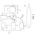
- the present inventionis generally directed to generation of diffuse infrared light. More particularly, the invention is directed to an apparatus for illuminating an object with diffuse infrared light, producing a video image of buried structure beneath the surface of the object based on reflected infrared light, and then projecting an image of the buried structure onto the surface of the object.
- Either one video imaging devicemay record two images, one in RANGE A and one in RANGE B, or two video imaging devices may each record one image in one of the ranges.
- the two images from the two rangesare then compared by an image processor by taking either the weighted difference of the two images with the formula A*I 1 ⁇ B*I 2 where A and B are constants, I 1 is the image in RANGE A, and I 2 is the image in RANGE B; the ratio of the two images with the formula I 1 /I 2 where I 1 is the image in RANGE A and I 2 is the image in RANGE B; or the ratio of the two images after a constant is added to one or both of the images with the formula (A+I 1 )/(B+I 2 ) where A and B are constants which could be zero, I 1 is the image in RANGE A and I 2 is the image in RANGE B to create a compared image.
- subcutaneous blood vesselsthat are difficult or impossible to see under white light or under non-diffuse infrared light can be easily seen in a video image, where the subcutaneous blood vessels appear as dark lines against a lighter background of surrounding flesh.
- FIG. 1depicts the apparatus in one possible preferred embodiment of the invention.
- FIG. 4Adepicts the unprocessed image of the left palm of a 62-year-old male, acquired using the FLIR ALPHA focal plane array camera at 950 nm.
- FIG. 5Ddepicts the ratio image FIG. 5C enhanced with large kernel and sharp masking.
- FIG. 7Cdepicts the image of FIG. 7A with edge enhancement.
- FIG. 7Ddepicts the ratio of the image at FIG. 7A and the image at FIG. 7B , after a constant has been added to the image at FIG. 7B .
- FIG. 8Fdepicts the unprocessed image of the left antecubital vein area of the 62-year-old male of FIG. 8A , acquired using the FLIR ALPHA focal plane array camera at 1,200 nm.
- FIG. 8Hdepicts the image generated by taking the ratio of the image at FIG. 8E and the image of FIG. 8F after a constant has been added to the image at FIG. 8F .
- FIG. 9Bdepicts the unprocessed image of the back of the left hand of the 62-year-old male of FIG. 9A , acquired using the FLIR ALPHA focal plane array camera at 1,200 nm.
- FIG. 10Cdepicts the image generated by taking the ratio of the image at FIG. 10A and the image at FIG. 10B after a constant has been added to the image at FIG. 10B .
- FIG. 10Edepicts the unprocessed image of the side of the left leg of the 24-year-old female of FIG. 10A acquired using the FLIR ALPHA focal plane array camera at 1,000 nm.
- FIG. 10Gdepicts the image generated by taking the ratio of the image at FIG. 10E and the image at FIG. 10F after a constant has been added to the image at FIG. 10F .
- the inventorhas also determined that deeper veins become invisible in the range of 1100 to 1700 nanometers, RANGE B, while the surface structure of the skin remains visible. Using this information, the imaging system may be improved by recording images in both RANGE A and RANGE B and “comparing” the two images.
- an arrangement of equipment as disclosed in U.S. patent application Ser. No. 10/386,246works for imaging in RANGE A, although the type of camera or other imaging device must accommodate receiving diffuse light and producing an image at the desired wavelength.
- an indium-gallium-arsenide focal plane array camerasuch as the FLIR Systems Alpha NIR camera, produces a good quality image and may be preferable, in some instances, to the CCD cameral disclosed in that application.
- the cold mirror 4transmits infrared light, or at least light in RANGE A and RANGE B, and reflects visible light.
- a hot mirror 6directs infrared light in RANGE A to a first imaging device 8 in front of which is a first filter 7 which filters the received light to only receive an appropriate wavelength.
- a preferred wavelength used in one embodiment of the inventionis 1000 nanometers.
- the first filter 7 in front of the first imaging device 8is a 1000 nanometer filter.
- the compared imageis transmitted via pathway 14 to a video projector 15 which projects a visible light image of the compared image, detailing the underlying vasculature, created by the image processor onto the surface of the skin 3 .
- the imagereaches the skin via the pathway of being generated by the video projector 15 , reflecting off of the cold mirror 4 and then reaching the surface of the skin 3 .
- the first imaging device 8may be either a Si CCD camera or an FLIR ALPHA focal plane array camera and the second imaging device 10 is an Indium-Gallium-Arsenide focal plane array camera such as the FLIR ALPHA focal plane array camera. This arrangement also works for performing the imaging of the buried structure without the comparison of two images if the second imaging device 10 is simply not used and the image processor 13 is used solely for applying unsharp masking or other image processing.
- FIG. 6A-FIG . 6 Das the white features on either side of the central vertical vein, they are significantly repressed in the ratio images, FIG. 6E-FIG . 6 G. This is another indication that the comparison of the two images is significant to remove non-vasculature structure, therefore providing a clearer image of just the vasculature to be reproducted onto the skin by the video projector.
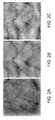
- FIGS. 9A-9Hshow image combination experiments using the FLIR Alpha camera on the back of the left hand of a 62-year-old male.
- the Alpha camerawas used in video capture mode and a filter wheel in front of the lens was rotated to select 1000 nanometer and 1200 nanometer band pass filters alternatively. In this experiment, 500 frames were captured at 30 frames per second and 2 images were required at each wavelength.
- FIGS. 9A and 9Eare images acquired at 1000 nanometers.
- FIGS. 9B and 9Fare images acquired at 1200 nanometers.
- FIGS. 9C and 9Gare the edge-enhanced versions of the image at FIG. 9A and the image at FIG. 9E respectively.
- FIG. 10GThe image at FIG. 10G was generated using the formula (A+I 1 )/(B+I 2 ) where A was zero, B was a constant, I 1 was the image at FIG. 10E , and I 2 was the image at FIG. 10F .
- FIG. 10C and FIG. 10Gshow that while skin structure is clearly visible in FIG. 10A and FIG. 10B , this comparison process removes the skin structure from the image leaving solely the vasculature, making the vasculature much more prominent and easily seen.
- FIG. 10Dis the edge-enhanced version of FIG. 10C
- FIG. 10His the edge-enhanced version of FIG. 10G .
Landscapes
- Health & Medical Sciences (AREA)
- Life Sciences & Earth Sciences (AREA)
- Medical Informatics (AREA)
- Biophysics (AREA)
- Pathology (AREA)
- Engineering & Computer Science (AREA)
- Biomedical Technology (AREA)
- Heart & Thoracic Surgery (AREA)
- Physics & Mathematics (AREA)
- Molecular Biology (AREA)
- Surgery (AREA)
- Animal Behavior & Ethology (AREA)
- General Health & Medical Sciences (AREA)
- Public Health (AREA)
- Veterinary Medicine (AREA)
- Vascular Medicine (AREA)
- Measurement Of The Respiration, Hearing Ability, Form, And Blood Characteristics Of Living Organisms (AREA)
- Measuring And Recording Apparatus For Diagnosis (AREA)
- Investigating Or Analysing Materials By Optical Means (AREA)
Abstract
Description
Claims (6)
Priority Applications (2)
| Application Number | Priority Date | Filing Date | Title |
|---|---|---|---|
| US11/683,851US8494616B2 (en) | 2000-01-19 | 2007-03-08 | Method and apparatus for projection of subsurface structure onto an object's surface |
| PCT/US2008/056151WO2008109799A1 (en) | 2007-03-08 | 2008-03-07 | Method and apparatus for projection of subsurface structure onto an object's surface |
Applications Claiming Priority (3)
| Application Number | Priority Date | Filing Date | Title |
|---|---|---|---|
| US09/487,007US6556858B1 (en) | 2000-01-19 | 2000-01-19 | Diffuse infrared light imaging system |
| US10/386,249US7239909B2 (en) | 2000-01-19 | 2003-03-11 | Imaging system using diffuse infrared light |
| US11/683,851US8494616B2 (en) | 2000-01-19 | 2007-03-08 | Method and apparatus for projection of subsurface structure onto an object's surface |
Related Parent Applications (1)
| Application Number | Title | Priority Date | Filing Date |
|---|---|---|---|
| US10/386,249Continuation-In-PartUS7239909B2 (en) | 2000-01-19 | 2003-03-11 | Imaging system using diffuse infrared light |
Publications (2)
| Publication Number | Publication Date |
|---|---|
| US20070158569A1 US20070158569A1 (en) | 2007-07-12 |
| US8494616B2true US8494616B2 (en) | 2013-07-23 |
Family
ID=39797993
Family Applications (1)
| Application Number | Title | Priority Date | Filing Date |
|---|---|---|---|
| US11/683,851Expired - Fee RelatedUS8494616B2 (en) | 2000-01-19 | 2007-03-08 | Method and apparatus for projection of subsurface structure onto an object's surface |
Country Status (2)
| Country | Link |
|---|---|
| US (1) | US8494616B2 (en) |
| WO (1) | WO2008109799A1 (en) |
Cited By (23)
| Publication number | Priority date | Publication date | Assignee | Title |
|---|---|---|---|---|
| US20080027317A1 (en)* | 2006-06-29 | 2008-01-31 | Fred Wood | Scanned laser vein contrast enhancer |
| US20110021925A1 (en)* | 2006-06-29 | 2011-01-27 | Fred Wood | Mounted vein contrast enchancer |
| US20120154636A1 (en)* | 2009-09-11 | 2012-06-21 | Koninklijke Philips Electronics N.V. | Illumination system for enhancing the appearance of an object and method thereof |
| US20140066781A1 (en)* | 2012-08-28 | 2014-03-06 | Electronics And Telecommunications Research Institute | Medical diagnosis device and method for controlling the device |
| US9042966B2 (en) | 2006-01-10 | 2015-05-26 | Accuvein, Inc. | Three dimensional imaging of veins |
| US9061109B2 (en) | 2009-07-22 | 2015-06-23 | Accuvein, Inc. | Vein scanner with user interface |
| US9072426B2 (en) | 2012-08-02 | 2015-07-07 | AccuVein, Inc | Device for detecting and illuminating vasculature using an FPGA |
| US9345427B2 (en) | 2006-06-29 | 2016-05-24 | Accuvein, Inc. | Method of using a combination vein contrast enhancer and bar code scanning device |
| US9430819B2 (en) | 2007-06-28 | 2016-08-30 | Accuvein, Inc. | Automatic alignment of a contrast enhancement system |
| US9492117B2 (en) | 2006-01-10 | 2016-11-15 | Accuvein, Inc. | Practitioner-mounted micro vein enhancer |
| US9854977B2 (en) | 2006-01-10 | 2018-01-02 | Accuvein, Inc. | Scanned laser vein contrast enhancer using a single laser, and modulation circuitry |
| US10238294B2 (en) | 2006-06-29 | 2019-03-26 | Accuvein, Inc. | Scanned laser vein contrast enhancer using one laser |
| US10376148B2 (en) | 2012-12-05 | 2019-08-13 | Accuvein, Inc. | System and method for laser imaging and ablation of cancer cells using fluorescence |
| US10813588B2 (en) | 2006-01-10 | 2020-10-27 | Accuvein, Inc. | Micro vein enhancer |
| US11051697B2 (en) | 2006-06-29 | 2021-07-06 | Accuvein, Inc. | Multispectral detection and presentation of an object's characteristics |
| US11207024B2 (en)* | 2017-07-12 | 2021-12-28 | Boe Technology Group Co., Ltd. | Vascular imaging apparatus and vascular imaging method |
| US11253198B2 (en) | 2006-01-10 | 2022-02-22 | Accuvein, Inc. | Stand-mounted scanned laser vein contrast enhancer |
| US11278240B2 (en) | 2006-01-10 | 2022-03-22 | Accuvein, Inc. | Trigger-actuated laser vein contrast enhancer |
| USD999379S1 (en) | 2010-07-22 | 2023-09-19 | Accuvein, Inc. | Vein imager and cradle in combination |
| US12048560B2 (en) | 2006-01-10 | 2024-07-30 | Accuvein, Inc. | Vein scanner configured for single-handed lifting and use |
| US12295744B2 (en) | 2006-01-10 | 2025-05-13 | Accuvein, Inc. | Micro vein enhancer with two lasers and two optical detectors configured for removing surface topology |
| US12303324B2 (en) | 2018-05-31 | 2025-05-20 | Faction Imaging Inc. | Method of medical imaging using multiple arrays |
| US12408865B2 (en) | 2006-01-10 | 2025-09-09 | Accuvein Inc. | Vein imaging device with differential image resolution at the center and the extremities of the vein image |
Families Citing this family (21)
| Publication number | Priority date | Publication date | Assignee | Title |
|---|---|---|---|---|
| US20070161906A1 (en)* | 2000-01-19 | 2007-07-12 | Luminetx Technologies Corporation | Method To Facilitate A Dermatological Procedure |
| JP2010538685A (en)* | 2007-07-17 | 2010-12-16 | エクスプレイ・リミテッド | Optical projection method and system |
| AU2009246917A1 (en) | 2008-05-13 | 2009-11-19 | Spectral Image, Inc. | Systems and methods for hyperspectral medical imaging using real-time projection of spectral information |
| US20090318815A1 (en)* | 2008-05-23 | 2009-12-24 | Michael Barnes | Systems and methods for hyperspectral medical imaging |
| US9117133B2 (en) | 2008-06-18 | 2015-08-25 | Spectral Image, Inc. | Systems and methods for hyperspectral imaging |
| DE102010007449B4 (en)* | 2010-02-10 | 2013-02-28 | Siemens Aktiengesellschaft | Arrangement and method for evaluating a test object by means of active thermography |
| GB2478903A (en)* | 2010-02-24 | 2011-09-28 | Brian Michael Harper | A combined infra-red camera/image projector viewing system for heat emission visualisation. |
| DE102010014744B4 (en)* | 2010-04-13 | 2013-07-11 | Siemens Aktiengesellschaft | Apparatus and method for projecting information onto an object in thermographic surveys |
| US9247906B2 (en) | 2011-06-28 | 2016-02-02 | Christie Digital Systems Usa, Inc. | Method and apparatus for detection of catheter location for intravenous access |
| DE102011089856A1 (en)* | 2011-12-23 | 2013-06-27 | Siemens Aktiengesellschaft | Inspection of a test object |
| US20140100550A1 (en) | 2012-10-10 | 2014-04-10 | Christie Digital Systems Canada Inc. | Catheter discrimination and guidance system |
| US9107567B2 (en) | 2012-12-27 | 2015-08-18 | Christie Digital Systems Usa, Inc. | Spectral imaging with a color wheel |
| CN103070674A (en)* | 2013-02-17 | 2013-05-01 | 北京望升伟业科技发展有限公司 | Venipuncture projector |
| JP6127207B2 (en) | 2013-05-13 | 2017-05-10 | 執鼎医療科技(杭州)有限公司 | Blood vessel image positioning system |
| US9298076B2 (en) | 2014-01-05 | 2016-03-29 | Hong Kong Applied Science and Technology Research Institute Company Limited | Image projector |
| WO2015198578A1 (en)* | 2014-06-25 | 2015-12-30 | パナソニックIpマネジメント株式会社 | Projection system |
| JP2018501839A (en)* | 2014-11-27 | 2018-01-25 | コーニンクレッカ フィリップス エヌ ヴェKoninklijke Philips N.V. | Imaging device and method for generating an image of a patient |
| EP3202315A4 (en)* | 2015-04-21 | 2018-06-20 | Olympus Corporation | Medical device and operating method for medical device |
| CN104799829A (en)* | 2015-05-18 | 2015-07-29 | 郑州麦德杰医疗科技有限公司 | Vein imaging system |
| US11553863B2 (en)* | 2019-08-01 | 2023-01-17 | Industrial Technology Research Institute | Venous positioning projector |
| CN110908232B (en)* | 2019-11-22 | 2025-08-08 | 合肥利弗莫尔仪器科技有限公司 | A position and angle adjustment device for infrared digital imaging mechanism |
Citations (22)
| Publication number | Priority date | Publication date | Assignee | Title |
|---|---|---|---|---|
| US4541438A (en)* | 1983-06-02 | 1985-09-17 | The Johns Hopkins University | Localization of cancerous tissue by monitoring infrared fluorescence emitted by intravenously injected porphyrin tumor-specific markers excited by long wavelength light |
| US4591918A (en)* | 1983-04-18 | 1986-05-27 | Omron Tateisi Electronics Co. | Image sensor system |
| US4817622A (en)* | 1986-07-22 | 1989-04-04 | Carl Pennypacker | Infrared imager for viewing subcutaneous location of vascular structures and method of use |
| US5519208A (en)* | 1994-09-29 | 1996-05-21 | Esparza; Joel | Infrared aided method and apparatus for venous examination |
| US5608210A (en) | 1994-09-29 | 1997-03-04 | Esparza; Joel | Infrared aided method and apparatus for venous examination |
| US5772593A (en)* | 1995-07-12 | 1998-06-30 | Fuji Photo Film Co., Ltd. | Surgical operation aiding system |
| US5787185A (en) | 1993-04-01 | 1998-07-28 | British Technology Group Ltd. | Biometric identification of individuals by use of subcutaneous vein patterns |
| US5969754A (en)* | 1996-12-09 | 1999-10-19 | Zeman; Herbert D. | Contrast enhancing illuminator |
| US6178340B1 (en) | 1998-08-24 | 2001-01-23 | Eduardo Svetliza | Three-dimensional infrared imager for subcutaneous puncture and study of vascular network |
| US6438396B1 (en) | 1998-11-05 | 2002-08-20 | Cytometrics, Inc. | Method and apparatus for providing high contrast imaging |
| US6556858B1 (en) | 2000-01-19 | 2003-04-29 | Herbert D. Zeman | Diffuse infrared light imaging system |
| US6600946B1 (en)* | 2000-08-11 | 2003-07-29 | The Boeing Company | Methods and apparatus for quantifying dermal hydration |
| US6665557B1 (en)* | 1999-12-01 | 2003-12-16 | The Research Foundation Of City College Of New York | Sprectroscopic and time-resolved optical methods and apparatus for imaging objects in turbed media |
| US20050008210A1 (en) | 2000-05-09 | 2005-01-13 | Paieon, Inc. | System and method for three-dimensional reconstruction of an artery |
| US20050157939A1 (en) | 2004-01-16 | 2005-07-21 | Mark Arsenault | Processes, products and systems for enhancing images of blood vessels |
| US6923762B1 (en) | 2001-11-01 | 2005-08-02 | Frank C. Creaghan, Jr. | Venoscope apparatus |
| US20050187478A1 (en)* | 2001-07-16 | 2005-08-25 | Art, Advanced Research Technologies Inc. | Multi-wavelength imaging of highly turbid media |
| US20050249399A1 (en) | 2004-05-06 | 2005-11-10 | Huseyin Tek | Artery-vein separation and vessel modeling |
| US7046835B2 (en) | 2002-03-07 | 2006-05-16 | Ge Medical Systems Global Technology Company Llc | Method and system for processing vascular radiographic images which have been reconstructed by three-dimensional modelling |
| US20060122515A1 (en) | 2000-01-19 | 2006-06-08 | Luminetx Corporation | Projection of subsurface structure onto an object's surface |
| US7239909B2 (en)* | 2000-01-19 | 2007-07-03 | Luminetx Technologies Corp. | Imaging system using diffuse infrared light |
| US7579592B2 (en) | 2000-02-25 | 2009-08-25 | Qinetiq Limited | Illumination and imaging devices and methods |
- 2007
- 2007-03-08USUS11/683,851patent/US8494616B2/ennot_activeExpired - Fee Related
- 2008
- 2008-03-07WOPCT/US2008/056151patent/WO2008109799A1/enactiveApplication Filing
Patent Citations (23)
| Publication number | Priority date | Publication date | Assignee | Title |
|---|---|---|---|---|
| US4591918A (en)* | 1983-04-18 | 1986-05-27 | Omron Tateisi Electronics Co. | Image sensor system |
| US4541438A (en)* | 1983-06-02 | 1985-09-17 | The Johns Hopkins University | Localization of cancerous tissue by monitoring infrared fluorescence emitted by intravenously injected porphyrin tumor-specific markers excited by long wavelength light |
| US4817622A (en)* | 1986-07-22 | 1989-04-04 | Carl Pennypacker | Infrared imager for viewing subcutaneous location of vascular structures and method of use |
| US5787185A (en) | 1993-04-01 | 1998-07-28 | British Technology Group Ltd. | Biometric identification of individuals by use of subcutaneous vein patterns |
| US5519208A (en)* | 1994-09-29 | 1996-05-21 | Esparza; Joel | Infrared aided method and apparatus for venous examination |
| US5608210A (en) | 1994-09-29 | 1997-03-04 | Esparza; Joel | Infrared aided method and apparatus for venous examination |
| US5772593A (en)* | 1995-07-12 | 1998-06-30 | Fuji Photo Film Co., Ltd. | Surgical operation aiding system |
| US5969754A (en)* | 1996-12-09 | 1999-10-19 | Zeman; Herbert D. | Contrast enhancing illuminator |
| US6178340B1 (en) | 1998-08-24 | 2001-01-23 | Eduardo Svetliza | Three-dimensional infrared imager for subcutaneous puncture and study of vascular network |
| US6650916B2 (en) | 1998-11-05 | 2003-11-18 | Cytoprop, L.L.C. | Method and apparatus for providing high contrast imaging |
| US6438396B1 (en) | 1998-11-05 | 2002-08-20 | Cytometrics, Inc. | Method and apparatus for providing high contrast imaging |
| US6665557B1 (en)* | 1999-12-01 | 2003-12-16 | The Research Foundation Of City College Of New York | Sprectroscopic and time-resolved optical methods and apparatus for imaging objects in turbed media |
| US6556858B1 (en) | 2000-01-19 | 2003-04-29 | Herbert D. Zeman | Diffuse infrared light imaging system |
| US20060122515A1 (en) | 2000-01-19 | 2006-06-08 | Luminetx Corporation | Projection of subsurface structure onto an object's surface |
| US7239909B2 (en)* | 2000-01-19 | 2007-07-03 | Luminetx Technologies Corp. | Imaging system using diffuse infrared light |
| US7579592B2 (en) | 2000-02-25 | 2009-08-25 | Qinetiq Limited | Illumination and imaging devices and methods |
| US20050008210A1 (en) | 2000-05-09 | 2005-01-13 | Paieon, Inc. | System and method for three-dimensional reconstruction of an artery |
| US6600946B1 (en)* | 2000-08-11 | 2003-07-29 | The Boeing Company | Methods and apparatus for quantifying dermal hydration |
| US20050187478A1 (en)* | 2001-07-16 | 2005-08-25 | Art, Advanced Research Technologies Inc. | Multi-wavelength imaging of highly turbid media |
| US6923762B1 (en) | 2001-11-01 | 2005-08-02 | Frank C. Creaghan, Jr. | Venoscope apparatus |
| US7046835B2 (en) | 2002-03-07 | 2006-05-16 | Ge Medical Systems Global Technology Company Llc | Method and system for processing vascular radiographic images which have been reconstructed by three-dimensional modelling |
| US20050157939A1 (en) | 2004-01-16 | 2005-07-21 | Mark Arsenault | Processes, products and systems for enhancing images of blood vessels |
| US20050249399A1 (en) | 2004-05-06 | 2005-11-10 | Huseyin Tek | Artery-vein separation and vessel modeling |
Cited By (70)
| Publication number | Priority date | Publication date | Assignee | Title |
|---|---|---|---|---|
| US9788787B2 (en) | 2006-01-10 | 2017-10-17 | Accuvein, Inc. | Patient-mounted micro vein enhancer |
| US11357449B2 (en) | 2006-01-10 | 2022-06-14 | Accuvein, Inc. | Micro vein enhancer for hands-free imaging for a venipuncture procedure |
| US12408865B2 (en) | 2006-01-10 | 2025-09-09 | Accuvein Inc. | Vein imaging device with differential image resolution at the center and the extremities of the vein image |
| US12295744B2 (en) | 2006-01-10 | 2025-05-13 | Accuvein, Inc. | Micro vein enhancer with two lasers and two optical detectors configured for removing surface topology |
| US10813588B2 (en) | 2006-01-10 | 2020-10-27 | Accuvein, Inc. | Micro vein enhancer |
| US11109806B2 (en) | 2006-01-10 | 2021-09-07 | Accuvein, Inc. | Three dimensional imaging of veins |
| US9042966B2 (en) | 2006-01-10 | 2015-05-26 | Accuvein, Inc. | Three dimensional imaging of veins |
| US9044207B2 (en) | 2006-01-10 | 2015-06-02 | Accuvein, Inc. | Micro vein enhancer for use with a vial holder |
| US12089951B2 (en) | 2006-01-10 | 2024-09-17 | AccuVeiw, Inc. | Scanned laser vein contrast enhancer with scanning correlated to target distance |
| US12048560B2 (en) | 2006-01-10 | 2024-07-30 | Accuvein, Inc. | Vein scanner configured for single-handed lifting and use |
| US9125629B2 (en) | 2006-01-10 | 2015-09-08 | Accuvein, Inc. | Vial-mounted micro vein enhancer |
| US10617352B2 (en) | 2006-01-10 | 2020-04-14 | Accuvein, Inc. | Patient-mounted micro vein enhancer |
| US11172880B2 (en) | 2006-01-10 | 2021-11-16 | Accuvein, Inc. | Vein imager with a dual buffer mode of operation |
| US11191482B2 (en) | 2006-01-10 | 2021-12-07 | Accuvein, Inc. | Scanned laser vein contrast enhancer imaging in an alternating frame mode |
| US11642080B2 (en) | 2006-01-10 | 2023-05-09 | Accuvein, Inc. | Portable hand-held vein-image-enhancing device |
| US9492117B2 (en) | 2006-01-10 | 2016-11-15 | Accuvein, Inc. | Practitioner-mounted micro vein enhancer |
| US9788788B2 (en) | 2006-01-10 | 2017-10-17 | AccuVein, Inc | Three dimensional imaging of veins |
| US11638558B2 (en) | 2006-01-10 | 2023-05-02 | Accuvein, Inc. | Micro vein enhancer |
| US11253198B2 (en) | 2006-01-10 | 2022-02-22 | Accuvein, Inc. | Stand-mounted scanned laser vein contrast enhancer |
| US11278240B2 (en) | 2006-01-10 | 2022-03-22 | Accuvein, Inc. | Trigger-actuated laser vein contrast enhancer |
| US11484260B2 (en) | 2006-01-10 | 2022-11-01 | Accuvein, Inc. | Patient-mounted micro vein enhancer |
| US9854977B2 (en) | 2006-01-10 | 2018-01-02 | Accuvein, Inc. | Scanned laser vein contrast enhancer using a single laser, and modulation circuitry |
| US9949688B2 (en) | 2006-01-10 | 2018-04-24 | Accuvein, Inc. | Micro vein enhancer with a dual buffer mode of operation |
| US10500350B2 (en) | 2006-01-10 | 2019-12-10 | Accuvein, Inc. | Combination vein contrast enhancer and bar code scanning device |
| US10470706B2 (en) | 2006-01-10 | 2019-11-12 | Accuvein, Inc. | Micro vein enhancer for hands-free imaging for a venipuncture procedure |
| US10258748B2 (en) | 2006-01-10 | 2019-04-16 | Accuvein, Inc. | Vein scanner with user interface for controlling imaging parameters |
| US11399768B2 (en) | 2006-01-10 | 2022-08-02 | Accuvein, Inc. | Scanned laser vein contrast enhancer utilizing surface topology |
| US10357200B2 (en)* | 2006-06-29 | 2019-07-23 | Accuvein, Inc. | Scanning laser vein contrast enhancer having releasable handle and scan head |
| US11051697B2 (en) | 2006-06-29 | 2021-07-06 | Accuvein, Inc. | Multispectral detection and presentation of an object's characteristics |
| US10238294B2 (en) | 2006-06-29 | 2019-03-26 | Accuvein, Inc. | Scanned laser vein contrast enhancer using one laser |
| US11523739B2 (en) | 2006-06-29 | 2022-12-13 | Accuvein, Inc. | Multispectral detection and presentation of an object's characteristics |
| US20080027317A1 (en)* | 2006-06-29 | 2008-01-31 | Fred Wood | Scanned laser vein contrast enhancer |
| US20110021925A1 (en)* | 2006-06-29 | 2011-01-27 | Fred Wood | Mounted vein contrast enchancer |
| US9345427B2 (en) | 2006-06-29 | 2016-05-24 | Accuvein, Inc. | Method of using a combination vein contrast enhancer and bar code scanning device |
| US9226664B2 (en) | 2006-06-29 | 2016-01-05 | Accuvein, Inc. | Scanned laser vein contrast enhancer using a single laser |
| US9186063B2 (en) | 2006-06-29 | 2015-11-17 | Accu Vein, Inc. | Scanned laser vein contrast enhancer using one laser for a detection mode and a display mode |
| US12193838B2 (en) | 2006-06-29 | 2025-01-14 | Accuvein, Inc. | Scanned laser vein contrast enhancer with reduced laser intensity during scan line reversals |
| US8838210B2 (en) | 2006-06-29 | 2014-09-16 | AccuView, Inc. | Scanned laser vein contrast enhancer using a single laser |
| US11051755B2 (en) | 2006-06-29 | 2021-07-06 | Accuvein, Inc. | Scanned laser vein contrast enhancer using a retro collective mirror |
| US9760982B2 (en) | 2007-06-28 | 2017-09-12 | Accuvein, Inc. | Automatic alignment of a contrast enhancement system |
| US10096096B2 (en) | 2007-06-28 | 2018-10-09 | Accuvein, Inc. | Automatic alignment of a contrast enhancement system |
| US11132774B2 (en) | 2007-06-28 | 2021-09-28 | Accuvein, Inc. | Automatic alignment of a contrast enhancement system |
| US10580119B2 (en) | 2007-06-28 | 2020-03-03 | Accuvein, Inc. | Automatic alignment of a contrast enhancement system |
| US10713766B2 (en) | 2007-06-28 | 2020-07-14 | Accuvein, Inc. | Automatic alignment of a contrast enhancement system |
| US11847768B2 (en) | 2007-06-28 | 2023-12-19 | Accuvein Inc. | Automatic alignment of a contrast enhancement system |
| US9430819B2 (en) | 2007-06-28 | 2016-08-30 | Accuvein, Inc. | Automatic alignment of a contrast enhancement system |
| US9061109B2 (en) | 2009-07-22 | 2015-06-23 | Accuvein, Inc. | Vein scanner with user interface |
| US10518046B2 (en) | 2009-07-22 | 2019-12-31 | Accuvein, Inc. | Vein scanner with user interface |
| US12433535B2 (en) | 2009-07-22 | 2025-10-07 | Accuvein, Inc. | Method and system for optimizing a projected vein image and identifying vein locations using vein scanner |
| US12426835B2 (en) | 2009-07-22 | 2025-09-30 | Accuvein, Inc. | Vein scanner with housing configured for single-handed lifting and use |
| US12318219B2 (en) | 2009-07-22 | 2025-06-03 | Accuvein Inc. | Vein scanner with limited photodiode FOV moving synchronously with scanned laser light |
| US11826166B2 (en) | 2009-07-22 | 2023-11-28 | Accuvein, Inc. | Vein scanner with housing configured for single-handed lifting and use |
| US9789267B2 (en) | 2009-07-22 | 2017-10-17 | Accuvein, Inc. | Vein scanner with user interface |
| USD999380S1 (en) | 2009-07-22 | 2023-09-19 | Accuvein, Inc. | Vein imager and cradle in combination |
| US8896752B2 (en)* | 2009-09-11 | 2014-11-25 | Koninklijke Philips N.V. | Illumination system for enhancing the appearance of an object and method thereof |
| US20120154636A1 (en)* | 2009-09-11 | 2012-06-21 | Koninklijke Philips Electronics N.V. | Illumination system for enhancing the appearance of an object and method thereof |
| USD998152S1 (en) | 2010-07-22 | 2023-09-05 | Accuvein, Inc. | Vein imager cradle |
| USD999379S1 (en) | 2010-07-22 | 2023-09-19 | Accuvein, Inc. | Vein imager and cradle in combination |
| US10568518B2 (en) | 2012-08-02 | 2020-02-25 | Accuvein, Inc. | Device for detecting and illuminating the vasculature using an FPGA |
| US9072426B2 (en) | 2012-08-02 | 2015-07-07 | AccuVein, Inc | Device for detecting and illuminating vasculature using an FPGA |
| US11510617B2 (en) | 2012-08-02 | 2022-11-29 | Accuvein, Inc. | Device for detecting and illuminating the vasculature using an FPGA |
| US9782079B2 (en) | 2012-08-02 | 2017-10-10 | Accuvein, Inc. | Device for detecting and illuminating the vasculature using an FPGA |
| US20140066781A1 (en)* | 2012-08-28 | 2014-03-06 | Electronics And Telecommunications Research Institute | Medical diagnosis device and method for controlling the device |
| US10376147B2 (en) | 2012-12-05 | 2019-08-13 | AccuVeiw, Inc. | System and method for multi-color laser imaging and ablation of cancer cells using fluorescence |
| US10517483B2 (en) | 2012-12-05 | 2019-12-31 | Accuvein, Inc. | System for detecting fluorescence and projecting a representative image |
| US11439307B2 (en) | 2012-12-05 | 2022-09-13 | Accuvein, Inc. | Method for detecting fluorescence and ablating cancer cells of a target surgical area |
| US10376148B2 (en) | 2012-12-05 | 2019-08-13 | Accuvein, Inc. | System and method for laser imaging and ablation of cancer cells using fluorescence |
| US11207024B2 (en)* | 2017-07-12 | 2021-12-28 | Boe Technology Group Co., Ltd. | Vascular imaging apparatus and vascular imaging method |
| US12303324B2 (en) | 2018-05-31 | 2025-05-20 | Faction Imaging Inc. | Method of medical imaging using multiple arrays |
| US12329569B2 (en) | 2018-05-31 | 2025-06-17 | Faction Imaging Inc. | Anatomical attachment device and associated method of use |
Also Published As
| Publication number | Publication date |
|---|---|
| US20070158569A1 (en) | 2007-07-12 |
| WO2008109799B1 (en) | 2008-12-18 |
| WO2008109799A1 (en) | 2008-09-12 |
Similar Documents
| Publication | Publication Date | Title |
|---|---|---|
| US8494616B2 (en) | Method and apparatus for projection of subsurface structure onto an object's surface | |
| US8078263B2 (en) | Projection of subsurface structure onto an object's surface | |
| US20100177184A1 (en) | System And Method For Projection of Subsurface Structure Onto An Object's Surface | |
| US20050157939A1 (en) | Processes, products and systems for enhancing images of blood vessels | |
| US20100051808A1 (en) | Imaging System Using Infrared Light | |
| US6556858B1 (en) | Diffuse infrared light imaging system | |
| US7239909B2 (en) | Imaging system using diffuse infrared light | |
| US7801335B2 (en) | Apparatus and methods for detecting the presence of a human eye | |
| US5947906A (en) | Apparatus for enhanced visual venous examination | |
| US20100061598A1 (en) | Apparatus and method for recognizing subcutaneous vein pattern | |
| JP4971531B2 (en) | Image processing device | |
| EP1906833B1 (en) | Projection of subsurface structure onto an object's surface | |
| JP6700703B2 (en) | Vein visualization device | |
| JP2007282965A (en) | Endoscope observation device | |
| TWI664950B (en) | Vein detection device | |
| CN109247910A (en) | Blood tube display apparatus and blood vessel display method | |
| WO2019240300A1 (en) | Ophthalmic photography apparatus and ophthalmic photography system | |
| CN118924424A (en) | Surgical navigation system and method for coaxially realizing near infrared two-region imaging and visible light projection | |
| US7336372B2 (en) | Noninvasive optical imaging by speckle ensemble | |
| Ramella-Roman et al. | Polarized light imaging with a handheld camera | |
| JPS61265126A (en) | Eyeground camera apparatus | |
| US6697156B1 (en) | Polarized material inspection apparatus | |
| KR20160069233A (en) | Vascular Venous Identification System And Its Methods | |
| KR20080043767A (en) | Apparatus and method for projecting an object substructure onto an object surface | |
| HK1142795A (en) | System and method for projection of subsurface structure onto an object's surface |
Legal Events
| Date | Code | Title | Description |
|---|---|---|---|
| AS | Assignment | Owner name:LUMINETX TECHNOLOGIES CORPORATION, TENNESSEE Free format text:ASSIGNMENT OF ASSIGNORS INTEREST;ASSIGNOR:ZEMAN, HERBERT D., DR.;REEL/FRAME:019123/0553 Effective date:20070329 | |
| AS | Assignment | Owner name:LUMINETX CORPORATION, TENNESSEE Free format text:MERGER;ASSIGNOR:LUMINETX TECHNOLOGIES CORPORATION;REEL/FRAME:021531/0368 Effective date:20080915 | |
| AS | Assignment | Owner name:CHRISTIE DIGITAL SYSTEMS, INC., CALIFORNIA Free format text:SECURITY AGREEMENT;ASSIGNOR:LUMINETX CORPORATION;REEL/FRAME:023222/0243 Effective date:20090817 Owner name:CHRISTIE DIGITAL SYSTEMS, INC.,CALIFORNIA Free format text:SECURITY AGREEMENT;ASSIGNOR:LUMINETX CORPORATION;REEL/FRAME:023222/0243 Effective date:20090817 | |
| AS | Assignment | Owner name:CHRISTIE MEDICAL HOLDINGS, INC., CALIFORNIA Free format text:PATENT ASSIGNMENT;ASSIGNOR:LUMINETX CORPORATION;REEL/FRAME:023814/0944 Effective date:20091231 Owner name:CHRISTIE MEDICAL HOLDINGS, INC.,CALIFORNIA Free format text:PATENT ASSIGNMENT;ASSIGNOR:LUMINETX CORPORATION;REEL/FRAME:023814/0944 Effective date:20091231 | |
| STCF | Information on status: patent grant | Free format text:PATENTED CASE | |
| FPAY | Fee payment | Year of fee payment:4 | |
| MAFP | Maintenance fee payment | Free format text:PAYMENT OF MAINTENANCE FEE, 8TH YEAR, LARGE ENTITY (ORIGINAL EVENT CODE: M1552); ENTITY STATUS OF PATENT OWNER: LARGE ENTITY Year of fee payment:8 | |
| FEPP | Fee payment procedure | Free format text:MAINTENANCE FEE REMINDER MAILED (ORIGINAL EVENT CODE: REM.); ENTITY STATUS OF PATENT OWNER: LARGE ENTITY | |
| LAPS | Lapse for failure to pay maintenance fees | Free format text:PATENT EXPIRED FOR FAILURE TO PAY MAINTENANCE FEES (ORIGINAL EVENT CODE: EXP.); ENTITY STATUS OF PATENT OWNER: LARGE ENTITY | |
| STCH | Information on status: patent discontinuation | Free format text:PATENT EXPIRED DUE TO NONPAYMENT OF MAINTENANCE FEES UNDER 37 CFR 1.362 | |
| FP | Lapsed due to failure to pay maintenance fee | Effective date:20250723 |