US8493695B1 - Method and system for providing a magnetic read transducer having an improved signal to noise ratio - Google Patents
Method and system for providing a magnetic read transducer having an improved signal to noise ratioDownload PDFInfo
- Publication number
- US8493695B1 US8493695B1US13/170,506US201113170506AUS8493695B1US 8493695 B1US8493695 B1US 8493695B1US 201113170506 AUS201113170506 AUS 201113170506AUS 8493695 B1US8493695 B1US 8493695B1
- Authority
- US
- United States
- Prior art keywords
- layer
- barrier layer
- spin pumping
- spin
- free
- Prior art date
- Legal status (The legal status is an assumption and is not a legal conclusion. Google has not performed a legal analysis and makes no representation as to the accuracy of the status listed.)
- Expired - Fee Related, expires
Links
Images


Classifications
- G—PHYSICS
- G11—INFORMATION STORAGE
- G11B—INFORMATION STORAGE BASED ON RELATIVE MOVEMENT BETWEEN RECORD CARRIER AND TRANSDUCER
- G11B5/00—Recording by magnetisation or demagnetisation of a record carrier; Reproducing by magnetic means; Record carriers therefor
- G11B5/127—Structure or manufacture of heads, e.g. inductive
- G11B5/33—Structure or manufacture of flux-sensitive heads, i.e. for reproduction only; Combination of such heads with means for recording or erasing only
- G11B5/39—Structure or manufacture of flux-sensitive heads, i.e. for reproduction only; Combination of such heads with means for recording or erasing only using magneto-resistive devices or effects
- G11B5/3903—Structure or manufacture of flux-sensitive heads, i.e. for reproduction only; Combination of such heads with means for recording or erasing only using magneto-resistive devices or effects using magnetic thin film layers or their effects, the films being part of integrated structures
- G11B5/3906—Details related to the use of magnetic thin film layers or to their effects
- G11B5/3909—Arrangements using a magnetic tunnel junction
- G—PHYSICS
- G01—MEASURING; TESTING
- G01R—MEASURING ELECTRIC VARIABLES; MEASURING MAGNETIC VARIABLES
- G01R33/00—Arrangements or instruments for measuring magnetic variables
- G01R33/02—Measuring direction or magnitude of magnetic fields or magnetic flux
- G01R33/06—Measuring direction or magnitude of magnetic fields or magnetic flux using galvano-magnetic devices
- G01R33/09—Magnetoresistive devices
- G01R33/093—Magnetoresistive devices using multilayer structures, e.g. giant magnetoresistance sensors
- G—PHYSICS
- G01—MEASURING; TESTING
- G01R—MEASURING ELECTRIC VARIABLES; MEASURING MAGNETIC VARIABLES
- G01R33/00—Arrangements or instruments for measuring magnetic variables
- G01R33/02—Measuring direction or magnitude of magnetic fields or magnetic flux
- G01R33/06—Measuring direction or magnitude of magnetic fields or magnetic flux using galvano-magnetic devices
- G01R33/09—Magnetoresistive devices
- G01R33/098—Magnetoresistive devices comprising tunnel junctions, e.g. tunnel magnetoresistance sensors
- G—PHYSICS
- G11—INFORMATION STORAGE
- G11B—INFORMATION STORAGE BASED ON RELATIVE MOVEMENT BETWEEN RECORD CARRIER AND TRANSDUCER
- G11B5/00—Recording by magnetisation or demagnetisation of a record carrier; Reproducing by magnetic means; Record carriers therefor
- G11B5/127—Structure or manufacture of heads, e.g. inductive
- G11B5/33—Structure or manufacture of flux-sensitive heads, i.e. for reproduction only; Combination of such heads with means for recording or erasing only
- G11B5/39—Structure or manufacture of flux-sensitive heads, i.e. for reproduction only; Combination of such heads with means for recording or erasing only using magneto-resistive devices or effects
- G11B5/3903—Structure or manufacture of flux-sensitive heads, i.e. for reproduction only; Combination of such heads with means for recording or erasing only using magneto-resistive devices or effects using magnetic thin film layers or their effects, the films being part of integrated structures
- G11B5/3906—Details related to the use of magnetic thin film layers or to their effects
- G11B5/3929—Disposition of magnetic thin films not used for directly coupling magnetic flux from the track to the MR film or for shielding
- H—ELECTRICITY
- H01—ELECTRIC ELEMENTS
- H01F—MAGNETS; INDUCTANCES; TRANSFORMERS; SELECTION OF MATERIALS FOR THEIR MAGNETIC PROPERTIES
- H01F41/00—Apparatus or processes specially adapted for manufacturing or assembling magnets, inductances or transformers; Apparatus or processes specially adapted for manufacturing materials characterised by their magnetic properties
- H01F41/32—Apparatus or processes specially adapted for manufacturing or assembling magnets, inductances or transformers; Apparatus or processes specially adapted for manufacturing materials characterised by their magnetic properties for applying conductive, insulating or magnetic material on a magnetic film, specially adapted for a thin magnetic film
- H01F41/325—Apparatus or processes specially adapted for manufacturing or assembling magnets, inductances or transformers; Apparatus or processes specially adapted for manufacturing materials characterised by their magnetic properties for applying conductive, insulating or magnetic material on a magnetic film, specially adapted for a thin magnetic film applying a noble metal capping on a spin-exchange-coupled multilayer, e.g. spin filter deposition
- H—ELECTRICITY
- H10—SEMICONDUCTOR DEVICES; ELECTRIC SOLID-STATE DEVICES NOT OTHERWISE PROVIDED FOR
- H10N—ELECTRIC SOLID-STATE DEVICES NOT OTHERWISE PROVIDED FOR
- H10N50/00—Galvanomagnetic devices
- H10N50/01—Manufacture or treatment
- H—ELECTRICITY
- H10—SEMICONDUCTOR DEVICES; ELECTRIC SOLID-STATE DEVICES NOT OTHERWISE PROVIDED FOR
- H10N—ELECTRIC SOLID-STATE DEVICES NOT OTHERWISE PROVIDED FOR
- H10N50/00—Galvanomagnetic devices
- H10N50/10—Magnetoresistive devices
- H—ELECTRICITY
- H01—ELECTRIC ELEMENTS
- H01F—MAGNETS; INDUCTANCES; TRANSFORMERS; SELECTION OF MATERIALS FOR THEIR MAGNETIC PROPERTIES
- H01F10/00—Thin magnetic films, e.g. of one-domain structure
- H01F10/32—Spin-exchange-coupled multilayers, e.g. nanostructured superlattices
- H01F10/324—Exchange coupling of magnetic film pairs via a very thin non-magnetic spacer, e.g. by exchange with conduction electrons of the spacer
- H01F10/3268—Exchange coupling of magnetic film pairs via a very thin non-magnetic spacer, e.g. by exchange with conduction electrons of the spacer the exchange coupling being asymmetric, e.g. by use of additional pinning, by using antiferromagnetic or ferromagnetic coupling interface, i.e. so-called spin-valve [SV] structure, e.g. NiFe/Cu/NiFe/FeMn
- H01F10/3272—Exchange coupling of magnetic film pairs via a very thin non-magnetic spacer, e.g. by exchange with conduction electrons of the spacer the exchange coupling being asymmetric, e.g. by use of additional pinning, by using antiferromagnetic or ferromagnetic coupling interface, i.e. so-called spin-valve [SV] structure, e.g. NiFe/Cu/NiFe/FeMn by use of anti-parallel coupled [APC] ferromagnetic layers, e.g. artificial ferrimagnets [AFI], artificial [AAF] or synthetic [SAF] anti-ferromagnets
Definitions
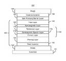
- FIG. 1depicts a portion of a conventional magnetic transducer 10 , such as a conventional read transducer or other device.
- the conventional transducer 10resides on a conventional substrate 11 , such as an AlTiC substrate.
- the conventional transducer 10includes a conventional bottom shield 12 , conventional sensor 20 , and conventional top shield 40 .
- the transducer 10also typically includes seed layer(s) (not shown) between the conventional AFM layer 22 and the conventional shield 12 .
- the conventional shields 12 and 40typically include NiFe and are formed by plating.
- the sensor 20is shown in a current-perpendicular to plane (CPP) configuration. In a CPP configuration, read current is driven generally perpendicular to the plane of the layers of the device, along the z-axis shown.
- CPPcurrent-perpendicular to plane
- the conventional sensor 20includes a conventional antiferromagnetic (AFM) layer 22 , a conventional synthetic antiferromagnet (SAF) 24 , a conventional tunneling barrier layer 32 , and a conventional free layer 34 . Also shown is a conventional capping layer 36 for the conventional sensor 20 .
- the conventional free layer 34has a magnetization that is substantially free to change direction in response to an applied magnetic field, for example from a bit being read.
- the conventional tunneling barrier layer 32may allow conduction through the sensor 20 via tunneling.
- the sensor 20is thus a tunneling magnetoresistive (TMR) sensor. Note that if a conductive spacer layer is used instead of the barrier layer 32 , then the sensor 20 is a spin valve.
- the conventional SAF layer 24typically includes two ferromagnetic layers 26 and 30 separated by a nonmagnetic spacer layer 28 .
- the ferromagnetic layersare generally antiferromagnetically coupled.
- the magnetization(s) of the conventional SAF layer 24are pinned by the conventional AFM layer 22 .
- the first ferromagnetic layer 26typically termed the pinned layer, has its magnetization pinned by the conventional AFM layer 22 , for example via exchange interaction.
- the remaining ferromagnetic layer, or reference layer 30has its magnetization pinned because it is strongly magnetically coupled with the pinned layer 26 .
- the conventional transducer 10may have limited utility.
- conventional sensor 20may be subject to noise.
- SNRsignal-to-noise ratio
- the magnetic read transducerincludes a magnetoresistive sensor a shield, and a spin pumping barrier layer.
- the magnetoresistive sensorincludes a pinned layer, a spacer layer, and a free layer.
- the spacer layeris nonmagnetic and resides between the pinned layer and the free layer.
- the free layeris between the pinned layer and the shield.
- the spin pumping barrier layeris between the shield and the free layer.
- FIG. 1is a diagram of a portion of a conventional transducer including a conventional sensor.
- FIG. 2depicts an exemplary embodiment of a head including an exemplary embodiment of a transducer.
- FIG. 3depicts an exemplary embodiment of a read transducer.
- FIG. 4depicts another exemplary embodiment of a read transducer.
- FIG. 5depicts another exemplary embodiment of a read transducer.
- FIG. 6depicts another exemplary embodiment of a read transducer.
- FIG. 7depicts an exemplary embodiment of a method of forming an exemplary embodiment of a read transducer.
- FIG. 2depicts a magnetic head 100 .
- FIG. 2is not to scale and not all components of the magnetic head 100 are shown.
- the magnetic head 100is a merged head that includes a magnetic write transducer 110 and a magnetic read transducer 150 .
- the read transducer 150 and write transducer 110may also be in separate heads.
- the magnetic head 100resides on a slider and is typically one of many magnetic heads in a disk drive and used to write to and read from a media (not shown).
- the write transducer 110includes a first pole 112 , auxiliary pole 116 , main pole 118 , write gap 120 , coils 114 and 122 , and return shield 124 .
- the write transducer 110includes other and/or different components.
- one or more portions of the write transducer 110might be omitted in various embodiments.
- the read transducer 150includes shields 152 and 154 , read sensor 160 , and spin pumping barrier layer 190 .
- the sensor 160may be used to read data from a media (not shown).
- the shields 152 and 154may be a soft magnetic material, such as NiFe.
- the shields 152 and 154magnetically isolate the sensor 160 from bits not being read during operation of the transducer 150 .
- the spin pumping barrier layer 190may be used to reduce or substantially eliminate spin pumping current from the sensor 160 to the shield 154 . Thermal fluctuations in a magnetic layer generate a spin current exiting the free layer. Thus, the spins in this current are oriented in the direction of the moment of the layer. This spin polarized current is the spin pumping current, which is a source of noise. As discussed below, the reduction in spin pumping current may reduce the noise from sensor 160 and thus improve performance of the transducer 150 .
- FIG. 3depicts an exemplary embodiment of the read transducer 150 as used in the magnetic recording head 100 .
- the transducer 150is also described in the context of particular layers. However, in some embodiments, such layers may include sub-layer(s).
- the read transducer 150is shown in a CPP configuration. Thus, sensor 160 is electrically connected to the shields 152 and 154 . However, in another embodiment, a gap may exist between the sensor 160 and the shields 152 and/or 154 . Further, a configuration other than CPP might be used.
- the read transducer 150is also described in the context of particular layers. However, in some embodiments, such layers may include sub-layer(s).
- the sensor 160includes a pinned layer 170 , a nonmagnetic layer 180 , and a free layer 185 .
- other componentsmay be included as part of the sensor 160 and/or the transducer 150 .
- the sensor 160might also include seed layer(s), and/or additional layers.
- the transducer 150may include capping layer(s) and/or additional layers.
- the pinned layer 170has its magnetization fixed, or pinned in place. This may be accomplished in a variety of ways.
- the pinned layer 170may be self-pinned or may be magnetically coupled with another layer, such as a pinning layer (not shown) that fixes the magnetization of the pinned layer 170 .
- a pinning layermay be a magnetically had layer that magnetically biases the pinned layer 170 or an antiferromagnetic (AFM) layer.
- the pinned layermay be a single, a multilayer such as a SAF, or other structure.
- the free layer 185includes one or more ferromagnetic layers (not separately shown in FIG. 3 ). At least some of these ferromagnetic layers may be spaced by nonmagnetic layers.
- the free layer 185is a sensor layer for the head 100 .
- the nonmagnetic layer 180separates the free layer 185 from the pinned layer 170 .
- the nonmagnetic layer 180may be desired to support a large magnetoresistance for the sensor 160 .
- the nonmagnetic layer 180is an insulating, tunneling barrier layer.
- the nonmagnetic layer 180may be a crystalline tunneling barrier layer.
- the crystalline tunneling barriermay include or be composed of crystalline MgO.
- the nonmagnetic layer 180may be conductive and/or have another structure.
- the spin pumping barrier layer 190may include at least one layer.
- the spin pumping barrier layer 190resides between the free layer 185 and the shield 154 .
- the spin pumping barrier layer 190adjoins the free layer 185 .
- the spin pumping barrier layer 190 and the free layer 185share an interface.
- one or more layer(s)may reside between the free layer 185 and the spin pumping barrier layer 190 .
- the spin pumping barrier layer 190is also shown as adjoining the shield 154 . However, in other embodiments, other layer(s) may be between the spin pumping barrier layer 190 and the shield 154 .
- the spin pumping barrier layer 190may reduce loss of spin information from the free layer 185 . More specifically, the spin pumping barrier layer 190 reduces the spin pumping current from the free layer 185 to the shield 154 . To do so, the spin pumping barrier layer 190 is generally desired to have a higher rate of momentum scattering, but a low rate of spin flip scattering for charge carriers. In some embodiments, the spin pumping barrier layer 190 is a non-spin flip scattering layer. Stated differently, charge carriers scattering from the spin pumping barrier layer 190 tend not to have their spins flipped by scattering. The charge carriers' spin information is thus preserved through the scattering. In some embodiments, the spin pumping barrier layer 190 is a tunneling barrier layer.
- the spin pumping barrier layer 190may include an insulator and/or a semiconductor. Materials that may be used include at least one of MgO, aluminum oxide, titanium oxide, tantalum oxide, zinc oxide, MgZnO, Si, Ge, ZnSe, Ta, and copper oxide. Further, the spin pumping barrier layer 190 need not support a large magnetoresistance for scattering occurring in the spin pumping barrier layer 190 . Consequently, the materials selected for the spin pumping barrier layer 190 need not have a high magnetoresistance. For example, the spin pumping barrier layer 190 need not include crystalline MgO. Instead, the spin pumping barrier layer 190 may include either crystalline MgO or amorphous MgO.
- the spin pumping barrier layer 190has a thickness not more than twenty-five Angstroms. In some such embodiments, the thickness of the spin pumping barrier layer 190 is at least five and not more than fifteen Angstroms. Such thicknesses may control the contribution of the spin pumping barrier layer 190 to the total resistance of the transducer 150 .
- the ability of the spin pumping barrier layer 190 to reduce spin pumpingmay also be characterized based on resistance area product (RA).
- the sensor 160has a sensor RA.
- the spin pumping barrier layer 190would then have an RA of not more than twenty percent of the sensor RA.
- the spin pumping barrier layer 190has a RA that is not more than ten percent of the sensor RA. Further, the RA of the spin pumping barrier layer 190 may be at least 0.1 m ⁇ - ⁇ m 2 . In other embodiments, the RA of the spin pumping barrier layer 190 is at least 10 m ⁇ - ⁇ m 2 . Finally, in some embodiments, the second RA of the spin pumping barrier layer 190 is not more than 100 m ⁇ - ⁇ m 2 .
- the spin pumping barrier layer 190thus has a small RA in comparison with the sensor 160 .
- the impedance of the read transducer 150is not significantly altered by the presence of the spin pumping barrier layer 190 .
- the charge carriers that do scatter from the spin pumping barrier layer 190have their spin information preserved.
- Charge carriers from the free layer 185 scattered by the spin pumping barrier layer 190may return to the free layer with their spin information intact.
- the net flow of angular momentum from the free layer 185may be reduced.
- the spin pumping current from the free layer 185is reduced.
- the spin pumping barrier layer 190may increase the signal-to-noise ratio (SNR) of the sensor 160 .
- the noise from the sensor 160is proportional to the temperature and damping constant of the free layer 185 and inversely proportional to the free layer magnetic moment and effective field.
- the damping constant of the free layer 185increases as the spin pumping current increases.
- the reduction in spin pumping current due to the spin pumping barrier layer 190reduces the damping constant of the free layer 185 . Consequently, the noise due to the free layer 185 is reduced.
- the SNR of the sensor 160may thus be increased. Consequently, performance of the sensor 160 and the transducer 150 may be enhanced.
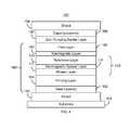
- FIG. 4depicts another exemplary embodiment of a read transducer 150 ′ including a spin barrier layer 190 ′.
- the transducer 150 ′is also described in the context of particular layers. However, in some embodiments, such layers may include sub-layer(s).
- the read transducer 150 ′is shown in a CPP configuration. Thus, sensor 160 ′ is electrically connected to the shields 152 ′ and 154 ′. However, in another embodiment, a gap may exist between the sensor 160 ′ and the shields 152 ′ and/or 154 ′. A configuration other than CPP may also be used.
- the read transducer 150 ′is also described in the context of particular layers. However, in some embodiments, such layers may include sub-layer(s).
- the transducer 150 ′thus includes shields 152 ′ and 154 ′, sensor 160 ′, and spin pumping barrier layer 190 ′ that are analogous to the shields 152 and 154 , sensor 160 , and spin pumping barrier layer 190 , respectively.
- the sensor 160 ′includes a pinned layer 170 ′, a nonmagnetic layer 180 ′, and a free layer 185 ′ that are analogous to the pinned layer 170 , the nonmagnetic spacer 180 , and the free layer 185 , respectively.
- a pinning layer 164 and capping layer 166are shown.
- the pinning layer 164may, for example, be an antiferromagnetic material such as PtMn and/or IrMn. However, other materials may be used.
- the pinned layer 170 ′is a SAF including a pinned layer 172 , a nonmagnetic spacer layer 174 , and a reference layer 176 .
- the pinned layer 172has its magnetization fixed, or pinned in place by the pinning layer 164 .
- the reference layer 176is magnetically coupled to the pinned layer 172 and has its magnetization fixed through this interaction.
- the pinned layer 170 ′may have another structure, such as a single layer or a multilayer.
- the free layer 185 ′includes one or more ferromagnetic layers (not separately shown in FIG. 4 ) and is the sensor layer for the sensor 160 ′. In some embodiments, the free layer 185 ′ may also include nonmagnetic layers.
- the nonmagnetic layer 180 ′separates the free layer 185 ′ from the pinned layer 170 ′.
- the nonmagnetic layer 180 ′may also be desired to support a large magnetoresistance for the sensor 160 ′.
- the nonmagnetic layer 180 ′is an insulating, tunneling barrier layer, such as crystalline MgO.
- the nonmagnetic layer 180 ′may be conductive and/or have another structure.
- the capping layer 166is nonmagnetic and may include materials such as Ta.
- the capping layer 166may have a long spin diffusion length.
- the spin diffusion lengthmay be five to ten times the thickness of the capping layer 166 .
- the capping layer 166may have a shorter spin diffusion length.
- a spin pumping barrier layer 190 ′analogous to the spin pumping barrier layer 190 ′.
- the spin pumping barrier layer 190 ′adjoins the free layer 185 ′.
- a layermay exist between the free layer 185 ′ and the spin pumping barrier layer 190 ′.
- the spin pumping barrier layer 190 ′is between the free layer 185 ′ and the scapping layer 166 pin pumping barrier layer 190 ′.
- the spin pumping barrier layer 190 ′may reduce loss of spin information for the free layer 185 ′ by reducing the spin pumping current from the free layer 185 ′ to the shield 154 ′.
- the spin pumping barrier layer 190 ′is a non-spin flip scattering layer.
- the spin pumping barrier layer 190 ′is a tunneling barrier layer.
- the spin pumping barrier layer 190 ′may include an insulator and/or a semiconductor such as the materials discussed above. Materials that may be used include at least one of crystalline or amorphous MgO, aluminum oxide, titanium oxide, tantalum oxide, zinc oxide, MgZnO, Si, Ge, ZnSe, Ta, and copper oxide.
- the spin pumping barrier layer 190 ′has a thickness not more than twenty-five Angstroms. In some such embodiments, the thickness of the spin pumping barrier layer 190 ′ is at least five and not more than fifteen Angstroms.
- the spin pumping barrier layer 190 ′may have an RA of not more than twenty percent of the sensor RA. In some such embodiments, the spin pumping barrier layer 190 ′ has a RA that is not more than ten percent of the sensor RA. Further, the RA of the spin pumping barrier layer 190 ′ may be at least 0.1 m ⁇ - ⁇ m 2 . In other embodiments, the RA of the spin pumping barrier layer 190 ′ is at least 10 m ⁇ - ⁇ m 2 . Finally, in some embodiments, the second RA of the spin pumping barrier layer 190 ′ is not more than 100 m ⁇ - ⁇ m 2 .
- the spin pumping barrier layer 190 ′may increase the signal-to-noise ratio (SNR) of the sensor 160 ′.
- the noise from the sensor 160 ′increases as the spin pumping current increases.
- the reduction in spin pumping current due to the spin pumping barrier layer 190 ′reduces the damping constant of the free layer 185 . Consequently, the noise due to the free layer 185 ′ is reduced.
- the SNR of the sensor 160 ′may thus be increased.
- the spin pumping barrier layer 190 ′has a small RA in comparison with the sensor 160 ′.
- the impedance of the read transducer 150 ′is asp not significantly altered by the presence of the spin pumping barrier layer 190 ′. Consequently, performance of the transducer 150 ′ may be enhanced.
- FIG. 5depicts another exemplary embodiment of a read transducer 150 ′′ including a spin barrier layer 190 ′′.
- the transducer 150 ′′is also described in the context of particular layers. However, in some embodiments, such layers may include sub-layer(s).
- the read transducer 150 ′′is shown in a CPP configuration. Thus, sensor 160 ′′ is electrically connected to the shields 152 ′′ and 154 ′′. However, in another embodiment, a gap may exist between the sensor 160 ′′ and the shields 152 ′′ and/or 154 ′′. A configuration other than CPP may also be used.
- the read transducer 150 ′′is also described in the context of particular layers. However, in some embodiments, such layers may include sub-layer(s).
- the transducer 150 ′′thus includes shields 152 ′′ and 154 ′′, sensor 160 ′′, and spin pumping barrier layer 190 ′′ that are analogous to the shields 152 / 152 ′ and 154 / 154 ′, sensor 160 / 160 ′, and spin pumping barrier layer 190 / 190 ′, respectively.
- the sensor 160 ′′includes a pinned layer 170 ′′, a nonmagnetic layer 180 ′′, and a free layer 185 ′′ that are analogous to the pinned layer 170 / 170 ′, the nonmagnetic spacer 180 / 180 ′, and the free layer 185 / 185 ′, respectively.
- a pinning layer 164 ′ and capping layer 166 ′are shown.
- the pinning layer 164 ′may, for example, be an antiferromagnetic material such as PtMn and/or IrMn. However, other materials may be used.
- the pinned layer 170 ′′is a SAF including a pinned layer 172 ′, a nonmagnetic spacer layer 174 ′, and a reference layer 176 ′.
- the pinned layer 170 ′′may have another structure, such as a single layer or a multilayer.
- the free layer 185 ′′includes one or more ferromagnetic layers (not separately shown in FIG. 5 ) and is the sensor layer for the sensor 160 ′′.
- the free layer 185 ′may also include nonmagnetic layers.
- the nonmagnetic layer 180 ′′separates the free layer 185 ′′ from the pinned layer 170 ′′.
- the nonmagnetic layer 180 ′′may be desired to support a large magnetoresistance for the sensor 160 ′′.
- the nonmagnetic layer 180 ′′is an insulating, tunneling barrier layer, such as crystalline MgO.
- the nonmagnetic layer 180 ′′may be conductive and/or have another structure.
- the capping layer 166 ′is nonmagnetic and may include materials such as Ta. In some embodiments, the capping layer 166 ′ may have a long spin diffusion length. A long spin diffusion length is greater than the thickness of the layer. In some embodiments, the long spin diffusion length for the capping layer 166 ′ may be five to ten times the thickness of the capping layer 166 ′. However, in other embodiments, the capping layer 166 ′ may have a shorter spin diffusion length.
- a spin pumping barrier layer 190 ′′analogous to the spin pumping barrier layer 190 ′′.
- the capping layer 166 ′is between the spin pumping barrier layer 190 ′′ and the free layer 185 ′′.
- a capping layer 166 ′ having a high spin diffusion lengthmay be desired.
- the spin pumping barrier layer 190 ′′may reduce loss of spin information for the free layer 185 ′′ by reducing the spin pumping current from the free layer 185 ′′ to the shield 154 ′′.
- the ability of the spin pumping barrier layer 190 ′′ to reduce this spin pumping currentmay be enhanced by a capping layer 166 ′ having a long spin diffusion length.
- charge carriers from the free layer 185 ′′are less likely to undergo spin flip scattering in the capping layer 166 .
- it is more likely that charge carriers from the free layer 185 ′′will retain their spin information upon reaching the spin pumping barrier layer 190 ′′.
- the spin pumping barrier layer 190 ′′may be better able to scatter charge carriers from the free layer 185 ′′ in a manner that preserves their spin original information.
- the scattered charge carriersare also more likely to return to the free layer 185 ′ without undergoing spin flip scattering in the capping layer 166 ′.
- the spin pumping barrier layer 190 ′′is a non-spin flip scattering layer.
- the spin pumping barrier layer 190 ′′is a tunneling barrier layer.
- the spin pumping barrier layer 190 ′′may include an insulator and/or a semiconductor. Materials that may be used include at least one of crystalline or amorphous MgO, aluminum oxide, titanium oxide, tantalum oxide, zinc oxide, MgZnO, Si, Ge, ZnSe, Ta, and copper oxide.
- the spin pumping barrier layer 190 ′′has a thickness not more than twenty-five Angstroms.
- the thickness of the spin pumping barrier layer 190 ′′is at least five and not more than fifteen Angstroms.
- the spin pumping barrier layer 190 ′′may have an RA of not more than twenty percent of the sensor RA. In some such embodiments, the spin pumping barrier layer 190 ′′ has a RA that is not more than ten percent of the sensor RA. Further, the RA of the spin pumping barrier layer 190 ′′ may be at least 0.1 m ⁇ - ⁇ m 2 . In other embodiments, the RA of the spin pumping barrier layer 190 ′′ is at least 10 m ⁇ - ⁇ m 2 . Finally, in some embodiments, the second RA of the spin pumping barrier layer 190 ′′ is not more than 100 m ⁇ - ⁇ m 2 .
- the transducer 150 ′′may share the benefits of the transducers 150 and 150 ′. More specifically, the noise from the sensor 160 ′′ may be reduced through a reduction in the spin pumping current from the free layer 185 ′′. The SNR of the sensor 160 ′′ may thus be increased. This benefit may be achieved without altering the RA of the sensor 190 ′′. Consequently, performance of the transducer 150 ′′ may be enhanced.
- FIG. 6depicts another exemplary embodiment of a read transducer 150 ′′′ including a spin barrier layer 190 ′′′.
- the transducer 150 ′′′is also described in the context of particular layers. However, in some embodiments, such layers may include sub-layer(s).
- the read transducer 150 ′′′is shown in a CPP configuration. Thus, sensor 160 ′′′ is electrically connected to the shields 152 ′′′ and 154 ′′′. However, in another embodiment, a gap may exist between the sensor 160 ′′′ and the shields 152 ′′′ and/or 154 ′′′. A configuration other than CPP may also be used.
- the read transducer 150 ′′′is also described in the context of particular layers. However, in some embodiments, such layers may include sub-layer(s).
- the transducer 150 ′′thus includes shields 152 ′′′ and 154 ′′′, sensor 160 ′′′, and spin pumping barrier layer 190 ′′′ that are analogous to the shields 152 / 152 ′/ 152 ′′ and 154 / 154 ′/ 154 ′′, sensor 160 / 160 ′/ 160 ′′, and spin pumping barrier layer 190 / 190 ′/ 190 ′′, respectively.
- the sensor 160 ′′′includes a pinned layer 170 ′′′, a nonmagnetic layer 180 ′′′, and a free layer 185 ′′′ that are analogous to the pinned layer 170 / 170 ′/ 170 ′′, the nonmagnetic spacer 180 / 180 ′/ 180 ′′, and the free layer 185 / 185 ′/ 185 ′′, respectively.
- a pinning layer 164 ′′ and capping layer 166 ′′are shown.
- the pinning layer 164 ′′may, for example, be an antiferromagnetic material such as PtMn and/or IrMn. However, other materials may be used.
- the pinned layer 170 ′′′is a SAF including a pinned layer 172 ′′, a nonmagnetic spacer layer 174 ′′, and a reference layer 176 ′′.
- the pinned layer 172 ′′has its magnetization fixed, or pinned in place by the pinning layer 164 ′′.
- the reference layer 176 ′′has its magnetization pinned by a magnetic coupling to the pinned layer 172 ′′.
- the free layer 185 ′′′includes one or more ferromagnetic layers (not separately shown in FIG. 6 ) and is the sensor layer for the sensor 160 ′′′.
- the nonmagnetic layer 180 ′′′separates the free layer 185 ′′′ from the pinned layer 170 ′′′.
- the nonmagnetic layer 180 ′′′may be desired to support a large magnetoresistance for the sensor 160 ′′′.
- the nonmagnetic layer 180 ′′′is an insulating, tunneling barrier layer, such as crystalline MgO.
- the nonmagnetic layer 180 ′′′may be conductive and/or have another structure.
- the capping layer 166 ′′is nonmagnetic and may include materials such as Ta.
- the capping layer 166 ′′may have a long spin diffusion length.
- a long spin diffusion lengthis greater than the thickness of the layer.
- the long spin diffusion length for the capping layer 166 ′′may be five to ten times the thickness of the capping layer 166 ′′.
- the capping layer 166 ′′may have a shorter spin diffusion length.
- a spin pumping barrier layer 190 ′′′analogous to the spin pumping barrier layer 190 ′′′.
- the spin pumping barrier layer 190 ′′′resides in the capping layer 166 ′′.
- the capping layer 166 ′′includes sublayers 166 A and 166 B.
- a capping layer 166 ′′ having a high spin diffusion lengthmay be desired for the reasons discussed with respect to FIG. 5 .
- the spin pumping barrier layer 190 ′′′may reduce loss of spin information for the free layer 185 ′′′ by reducing the spin pumping current from the free layer 185 ′′′ to the shield 154 ′′′.
- the ability of the spin pumping barrier layer 190 ′′′ to reduce this spin pumping currentmay be enhanced by a capping layer 166 ′′ having a long spin diffusion length.
- charge carriers from the free layer 185 ′′′are less likely to scatter in the capping layer 166 ′′.
- it is more likely that charge carriers from the free layer 185 ′′′will retain their spin information upon reaching the spin pumping barrier layer 190 ′′′.
- the spin pumping barrier layer 190 ′′′may be better able to scatter charge carriers from the free layer 185 ′′′ in a manner that preserves their spin original information.
- the spin pumping barrier layer 190 ′′′is a non-spin flip scattering layer.
- the spin pumping barrier layer 190 ′′′is a tunneling barrier layer.
- the spin pumping barrier layer 190 ′′′may include an insulator and/or a semiconductor. Materials that may be used include at least one of crystalline or amorphous MgO, aluminum oxide, titanium oxide, tantalum oxide, zinc oxide, MgZnO, Si, Ge, ZnSe, Ta, and copper oxide.
- the spin pumping barrier layer 190 ′′′has a thickness not more than twenty-five Angstroms.
- the thickness of the spin pumping barrier layer 190 ′′′is at least five and not more than fifteen Angstroms.
- the spin pumping barrier layer 190 ′′′may have an RA of not more than twenty percent of the sensor RA.
- the spin pumping barrier layer 190 ′′has a RA that is not more than ten percent of the sensor RA.
- the RA of the spin pumping barrier layer 190 ′′′may be at least 0.1 m ⁇ - ⁇ m 2 .
- the RA of the spin pumping barrier layer 190 ′′′is at least 10 m ⁇ - ⁇ m 2 .
- the second RA of the spin pumping barrier layer 190 ′′′is not more than 100 m ⁇ - ⁇ m 2 .
- the transducer 150 ′′′may share the benefits of the transducers 150 , 150 ′, and 150 ′′. More specifically, the noise from the sensor 160 ′′′ may be reduced through a reduction in the spin pumping current from the free layer 185 ′′′. The SNR of the sensor 160 ′′′ may thus be increased. This benefit may be achieved without altering the RA of the sensor 190 ′′′. Consequently, performance of the transducer 150 ′′′ may be enhanced.
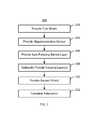
- FIG. 7depicts an exemplary embodiment of a method 200 of forming an exemplary embodiment of a read transducer including a spin pumping barrier layer.
- the method 300is described in the context of the transducers 150 / 150 ′/ 150 ′′/ 150 ′′′. However, the method 200 may be used for other transducers. The method 200 also may commence after formation of other structures of the read and/or write transducer. The method 200 is also described in the context of providing a single transducer 150 / 150 ′/ 150 ′′/ 150 ′′′. However, the method 200 may be used to fabricate multiple structures at substantially the same time.
- the method 200 and structures such as the transducers 150 / 150 ′/ 150 ′′/ 150 ′′′are also described in the context of particular layers. However, in some embodiments, such layers may include sub-layer(s).
- the first shield 152 / 152 ′/ 152 ′′/ 152 ′′is provided, via step 202 .
- the first shield 152 / 152 ′/ 152 ′′/ 152 ′′′is plated on the substrate 151 / 151 ′/ 151 ′′/ 151 ′′′.
- first shield 152 / 152 ′/ 152 ′′/ 152 ′′is deposited in another manner and/or on another structure.
- step 204includes depositing a stack including the layers for the magnetoresistive sensor 160 / 160 ′/ 160 ′′/ 160 ′′′ and defining the magnetoresistive sensor 160 / 160 ′/ 160 ′′/ 160 ′′′ from the stack.
- Step 204may also include providing insulating layers, hard bias layers and/or other structures.
- the spin pumping barrier layer 190 / 190 ′/ 190 ′′/ 190 ′′′is provided, via step 206 .
- Step 206may include providing a barrier layer or other structure.
- the capping layer 166 / 166 ′/ 166 ′′may also optionally be provided, via step 208 .
- step 208may be performed before step 206 .
- steps 208 and 206may be interleaved.
- Step 208may include depositing layer(s) such as Ta. Deposition of the spin pumping barrier layer 190 in step 206 and/or the capping layer 166 in step 208 may be performed as part of deposition of the read sensor stack in step 204 .
- the second shield 154 / 154 ′/ 154 ′′/ 154 ′′may then be provided, via step 210 .
- Step 210may be performed in a manner analogous to step 202 . Fabrication of the transducer 150 / 150 ′/ 150 ′′/ 150 ′′′ may then be completed, via step 212 .
- transducer 150 / 150 ′/ 150 ′′/ 150 ′′′may be completed.
- the benefits of the transducers 150 / 150 ′/ 150 ′′/ 150 ′′′may be achieved.
Landscapes
- Engineering & Computer Science (AREA)
- Manufacturing & Machinery (AREA)
- Physics & Mathematics (AREA)
- Power Engineering (AREA)
- Condensed Matter Physics & Semiconductors (AREA)
- General Physics & Mathematics (AREA)
- Hall/Mr Elements (AREA)
- Magnetic Heads (AREA)
Abstract
Description
Claims (23)
Priority Applications (1)
| Application Number | Priority Date | Filing Date | Title |
|---|---|---|---|
| US13/170,506US8493695B1 (en) | 2011-06-28 | 2011-06-28 | Method and system for providing a magnetic read transducer having an improved signal to noise ratio |
Applications Claiming Priority (1)
| Application Number | Priority Date | Filing Date | Title |
|---|---|---|---|
| US13/170,506US8493695B1 (en) | 2011-06-28 | 2011-06-28 | Method and system for providing a magnetic read transducer having an improved signal to noise ratio |
Publications (1)
| Publication Number | Publication Date |
|---|---|
| US8493695B1true US8493695B1 (en) | 2013-07-23 |
Family
ID=48792371
Family Applications (1)
| Application Number | Title | Priority Date | Filing Date |
|---|---|---|---|
| US13/170,506Expired - Fee RelatedUS8493695B1 (en) | 2011-06-28 | 2011-06-28 | Method and system for providing a magnetic read transducer having an improved signal to noise ratio |
Country Status (1)
| Country | Link |
|---|---|
| US (1) | US8493695B1 (en) |
Cited By (135)
| Publication number | Priority date | Publication date | Assignee | Title |
|---|---|---|---|---|
| US8830628B1 (en) | 2009-02-23 | 2014-09-09 | Western Digital (Fremont), Llc | Method and system for providing a perpendicular magnetic recording head |
| US20140252519A1 (en)* | 2013-03-11 | 2014-09-11 | Kee-Won Kim | Magnetoresistive structures, magnetic random-access memory devices including the same and methods of manufacturing the magnetoresistive structure |
| US8879207B1 (en) | 2011-12-20 | 2014-11-04 | Western Digital (Fremont), Llc | Method for providing a side shield for a magnetic recording transducer using an air bridge |
| US8883017B1 (en) | 2013-03-12 | 2014-11-11 | Western Digital (Fremont), Llc | Method and system for providing a read transducer having seamless interfaces |
| US20140363902A1 (en)* | 2013-06-06 | 2014-12-11 | International Business Machines Corporation | Magnetic materials with enhanced perpendicular anisotropy energy density for stt-ram |
| US20140367814A1 (en)* | 2013-06-17 | 2014-12-18 | Sony Corporation | Storage element, storage device, method of manufacturing storage element, and magnetic head |
| US8917581B1 (en) | 2013-12-18 | 2014-12-23 | Western Digital Technologies, Inc. | Self-anneal process for a near field transducer and chimney in a hard disk drive assembly |
| US8923102B1 (en) | 2013-07-16 | 2014-12-30 | Western Digital (Fremont), Llc | Optical grating coupling for interferometric waveguides in heat assisted magnetic recording heads |
| US8947985B1 (en) | 2013-07-16 | 2015-02-03 | Western Digital (Fremont), Llc | Heat assisted magnetic recording transducers having a recessed pole |
| US8953422B1 (en) | 2014-06-10 | 2015-02-10 | Western Digital (Fremont), Llc | Near field transducer using dielectric waveguide core with fine ridge feature |
| US8958272B1 (en) | 2014-06-10 | 2015-02-17 | Western Digital (Fremont), Llc | Interfering near field transducer for energy assisted magnetic recording |
| US8971160B1 (en) | 2013-12-19 | 2015-03-03 | Western Digital (Fremont), Llc | Near field transducer with high refractive index pin for heat assisted magnetic recording |
| US8970988B1 (en) | 2013-12-31 | 2015-03-03 | Western Digital (Fremont), Llc | Electric gaps and method for making electric gaps for multiple sensor arrays |
| US8976635B1 (en) | 2014-06-10 | 2015-03-10 | Western Digital (Fremont), Llc | Near field transducer driven by a transverse electric waveguide for energy assisted magnetic recording |
| US8982508B1 (en) | 2011-10-31 | 2015-03-17 | Western Digital (Fremont), Llc | Method for providing a side shield for a magnetic recording transducer |
| US8980109B1 (en) | 2012-12-11 | 2015-03-17 | Western Digital (Fremont), Llc | Method for providing a magnetic recording transducer using a combined main pole and side shield CMP for a wraparound shield scheme |
| US8988812B1 (en) | 2013-11-27 | 2015-03-24 | Western Digital (Fremont), Llc | Multi-sensor array configuration for a two-dimensional magnetic recording (TDMR) operation |
| US8984740B1 (en) | 2012-11-30 | 2015-03-24 | Western Digital (Fremont), Llc | Process for providing a magnetic recording transducer having a smooth magnetic seed layer |
| US8988825B1 (en) | 2014-02-28 | 2015-03-24 | Western Digital (Fremont, LLC | Method for fabricating a magnetic writer having half-side shields |
| US8995087B1 (en) | 2006-11-29 | 2015-03-31 | Western Digital (Fremont), Llc | Perpendicular magnetic recording write head having a wrap around shield |
| US8993217B1 (en) | 2013-04-04 | 2015-03-31 | Western Digital (Fremont), Llc | Double exposure technique for high resolution disk imaging |
| US9001467B1 (en) | 2014-03-05 | 2015-04-07 | Western Digital (Fremont), Llc | Method for fabricating side shields in a magnetic writer |
| US8997832B1 (en) | 2010-11-23 | 2015-04-07 | Western Digital (Fremont), Llc | Method of fabricating micrometer scale components |
| US9001628B1 (en) | 2013-12-16 | 2015-04-07 | Western Digital (Fremont), Llc | Assistant waveguides for evaluating main waveguide coupling efficiency and diode laser alignment tolerances for hard disk |
| US9007879B1 (en) | 2014-06-10 | 2015-04-14 | Western Digital (Fremont), Llc | Interfering near field transducer having a wide metal bar feature for energy assisted magnetic recording |
| US9007719B1 (en) | 2013-10-23 | 2015-04-14 | Western Digital (Fremont), Llc | Systems and methods for using double mask techniques to achieve very small features |
| US9007725B1 (en) | 2014-10-07 | 2015-04-14 | Western Digital (Fremont), Llc | Sensor with positive coupling between dual ferromagnetic free layer laminates |
| US9013836B1 (en) | 2013-04-02 | 2015-04-21 | Western Digital (Fremont), Llc | Method and system for providing an antiferromagnetically coupled return pole |
| US9042051B2 (en) | 2013-08-15 | 2015-05-26 | Western Digital (Fremont), Llc | Gradient write gap for perpendicular magnetic recording writer |
| US9042208B1 (en) | 2013-03-11 | 2015-05-26 | Western Digital Technologies, Inc. | Disk drive measuring fly height by applying a bias voltage to an electrically insulated write component of a head |
| US9042057B1 (en) | 2013-01-09 | 2015-05-26 | Western Digital (Fremont), Llc | Methods for providing magnetic storage elements with high magneto-resistance using Heusler alloys |
| US9042052B1 (en) | 2014-06-23 | 2015-05-26 | Western Digital (Fremont), Llc | Magnetic writer having a partially shunted coil |
| US9042058B1 (en) | 2013-10-17 | 2015-05-26 | Western Digital Technologies, Inc. | Shield designed for middle shields in a multiple sensor array |
| US9053735B1 (en) | 2014-06-20 | 2015-06-09 | Western Digital (Fremont), Llc | Method for fabricating a magnetic writer using a full-film metal planarization |
| US9059389B2 (en) | 2013-06-06 | 2015-06-16 | International Business Machines Corporation | Free layers with iron interfacial layer and oxide cap for high perpendicular anisotropy energy density |
| US9064528B1 (en) | 2013-05-17 | 2015-06-23 | Western Digital Technologies, Inc. | Interferometric waveguide usable in shingled heat assisted magnetic recording in the absence of a near-field transducer |
| US9064507B1 (en) | 2009-07-31 | 2015-06-23 | Western Digital (Fremont), Llc | Magnetic etch-stop layer for magnetoresistive read heads |
| US9065043B1 (en) | 2012-06-29 | 2015-06-23 | Western Digital (Fremont), Llc | Tunnel magnetoresistance read head with narrow shield-to-shield spacing |
| US9064527B1 (en) | 2013-04-12 | 2015-06-23 | Western Digital (Fremont), Llc | High order tapered waveguide for use in a heat assisted magnetic recording head |
| US9070381B1 (en) | 2013-04-12 | 2015-06-30 | Western Digital (Fremont), Llc | Magnetic recording read transducer having a laminated free layer |
| US9082423B1 (en) | 2013-12-18 | 2015-07-14 | Western Digital (Fremont), Llc | Magnetic recording write transducer having an improved trailing surface profile |
| US9087534B1 (en) | 2011-12-20 | 2015-07-21 | Western Digital (Fremont), Llc | Method and system for providing a read transducer having soft and hard magnetic bias structures |
| US9087527B1 (en) | 2014-10-28 | 2015-07-21 | Western Digital (Fremont), Llc | Apparatus and method for middle shield connection in magnetic recording transducers |
| US9087543B2 (en) | 2013-06-06 | 2015-07-21 | International Business Machines Corporation | Spin torque MRAM having perpendicular magnetization with oxide interface |
| US9093639B2 (en) | 2012-02-21 | 2015-07-28 | Western Digital (Fremont), Llc | Methods for manufacturing a magnetoresistive structure utilizing heating and cooling |
| US9104107B1 (en) | 2013-04-03 | 2015-08-11 | Western Digital (Fremont), Llc | DUV photoresist process |
| US9111558B1 (en) | 2014-03-14 | 2015-08-18 | Western Digital (Fremont), Llc | System and method of diffractive focusing of light in a waveguide |
| US9111550B1 (en) | 2014-12-04 | 2015-08-18 | Western Digital (Fremont), Llc | Write transducer having a magnetic buffer layer spaced between a side shield and a write pole by non-magnetic layers |
| US9111564B1 (en) | 2013-04-02 | 2015-08-18 | Western Digital (Fremont), Llc | Magnetic recording writer having a main pole with multiple flare angles |
| US9123358B1 (en) | 2012-06-11 | 2015-09-01 | Western Digital (Fremont), Llc | Conformal high moment side shield seed layer for perpendicular magnetic recording writer |
| US9123362B1 (en) | 2011-03-22 | 2015-09-01 | Western Digital (Fremont), Llc | Methods for assembling an electrically assisted magnetic recording (EAMR) head |
| US9123359B1 (en) | 2010-12-22 | 2015-09-01 | Western Digital (Fremont), Llc | Magnetic recording transducer with sputtered antiferromagnetic coupling trilayer between plated ferromagnetic shields and method of fabrication |
| US9123374B1 (en) | 2015-02-12 | 2015-09-01 | Western Digital (Fremont), Llc | Heat assisted magnetic recording writer having an integrated polarization rotation plate |
| US9135930B1 (en) | 2014-03-06 | 2015-09-15 | Western Digital (Fremont), Llc | Method for fabricating a magnetic write pole using vacuum deposition |
| US9135937B1 (en) | 2014-05-09 | 2015-09-15 | Western Digital (Fremont), Llc | Current modulation on laser diode for energy assisted magnetic recording transducer |
| US9142233B1 (en) | 2014-02-28 | 2015-09-22 | Western Digital (Fremont), Llc | Heat assisted magnetic recording writer having a recessed pole |
| US9147404B1 (en) | 2015-03-31 | 2015-09-29 | Western Digital (Fremont), Llc | Method and system for providing a read transducer having a dual free layer |
| US9147408B1 (en) | 2013-12-19 | 2015-09-29 | Western Digital (Fremont), Llc | Heated AFM layer deposition and cooling process for TMR magnetic recording sensor with high pinning field |
| US9153255B1 (en) | 2014-03-05 | 2015-10-06 | Western Digital (Fremont), Llc | Method for fabricating a magnetic writer having an asymmetric gap and shields |
| US9183854B2 (en) | 2014-02-24 | 2015-11-10 | Western Digital (Fremont), Llc | Method to make interferometric taper waveguide for HAMR light delivery |
| US9190085B1 (en) | 2014-03-12 | 2015-11-17 | Western Digital (Fremont), Llc | Waveguide with reflective grating for localized energy intensity |
| US9190079B1 (en) | 2014-09-22 | 2015-11-17 | Western Digital (Fremont), Llc | Magnetic write pole having engineered radius of curvature and chisel angle profiles |
| US9194692B1 (en) | 2013-12-06 | 2015-11-24 | Western Digital (Fremont), Llc | Systems and methods for using white light interferometry to measure undercut of a bi-layer structure |
| US9202480B2 (en) | 2009-10-14 | 2015-12-01 | Western Digital (Fremont), LLC. | Double patterning hard mask for damascene perpendicular magnetic recording (PMR) writer |
| US9202493B1 (en) | 2014-02-28 | 2015-12-01 | Western Digital (Fremont), Llc | Method of making an ultra-sharp tip mode converter for a HAMR head |
| US9214172B2 (en) | 2013-10-23 | 2015-12-15 | Western Digital (Fremont), Llc | Method of manufacturing a magnetic read head |
| US9214165B1 (en) | 2014-12-18 | 2015-12-15 | Western Digital (Fremont), Llc | Magnetic writer having a gradient in saturation magnetization of the shields |
| US9214169B1 (en) | 2014-06-20 | 2015-12-15 | Western Digital (Fremont), Llc | Magnetic recording read transducer having a laminated free layer |
| US9213322B1 (en) | 2012-08-16 | 2015-12-15 | Western Digital (Fremont), Llc | Methods for providing run to run process control using a dynamic tuner |
| US9230565B1 (en) | 2014-06-24 | 2016-01-05 | Western Digital (Fremont), Llc | Magnetic shield for magnetic recording head |
| US9236560B1 (en) | 2014-12-08 | 2016-01-12 | Western Digital (Fremont), Llc | Spin transfer torque tunneling magnetoresistive device having a laminated free layer with perpendicular magnetic anisotropy |
| US9245545B1 (en) | 2013-04-12 | 2016-01-26 | Wester Digital (Fremont), Llc | Short yoke length coils for magnetic heads in disk drives |
| US9245562B1 (en) | 2015-03-30 | 2016-01-26 | Western Digital (Fremont), Llc | Magnetic recording writer with a composite main pole |
| US9245543B1 (en) | 2010-06-25 | 2016-01-26 | Western Digital (Fremont), Llc | Method for providing an energy assisted magnetic recording head having a laser integrally mounted to the slider |
| US9251813B1 (en) | 2009-04-19 | 2016-02-02 | Western Digital (Fremont), Llc | Method of making a magnetic recording head |
| US9263071B1 (en) | 2015-03-31 | 2016-02-16 | Western Digital (Fremont), Llc | Flat NFT for heat assisted magnetic recording |
| US9263067B1 (en) | 2013-05-29 | 2016-02-16 | Western Digital (Fremont), Llc | Process for making PMR writer with constant side wall angle |
| US9269382B1 (en) | 2012-06-29 | 2016-02-23 | Western Digital (Fremont), Llc | Method and system for providing a read transducer having improved pinning of the pinned layer at higher recording densities |
| US9275657B1 (en) | 2013-08-14 | 2016-03-01 | Western Digital (Fremont), Llc | Process for making PMR writer with non-conformal side gaps |
| US9280990B1 (en) | 2013-12-11 | 2016-03-08 | Western Digital (Fremont), Llc | Method for fabricating a magnetic writer using multiple etches |
| US9286919B1 (en) | 2014-12-17 | 2016-03-15 | Western Digital (Fremont), Llc | Magnetic writer having a dual side gap |
| US9287494B1 (en) | 2013-06-28 | 2016-03-15 | Western Digital (Fremont), Llc | Magnetic tunnel junction (MTJ) with a magnesium oxide tunnel barrier |
| US9305583B1 (en) | 2014-02-18 | 2016-04-05 | Western Digital (Fremont), Llc | Method for fabricating a magnetic writer using multiple etches of damascene materials |
| US9312064B1 (en) | 2015-03-02 | 2016-04-12 | Western Digital (Fremont), Llc | Method to fabricate a magnetic head including ion milling of read gap using dual layer hard mask |
| US9318130B1 (en) | 2013-07-02 | 2016-04-19 | Western Digital (Fremont), Llc | Method to fabricate tunneling magnetic recording heads with extended pinned layer |
| US9336814B1 (en) | 2013-03-12 | 2016-05-10 | Western Digital (Fremont), Llc | Inverse tapered waveguide for use in a heat assisted magnetic recording head |
| US9343098B1 (en) | 2013-08-23 | 2016-05-17 | Western Digital (Fremont), Llc | Method for providing a heat assisted magnetic recording transducer having protective pads |
| US9343086B1 (en) | 2013-09-11 | 2016-05-17 | Western Digital (Fremont), Llc | Magnetic recording write transducer having an improved sidewall angle profile |
| US9343087B1 (en) | 2014-12-21 | 2016-05-17 | Western Digital (Fremont), Llc | Method for fabricating a magnetic writer having half shields |
| US9349392B1 (en) | 2012-05-24 | 2016-05-24 | Western Digital (Fremont), Llc | Methods for improving adhesion on dielectric substrates |
| US9349394B1 (en) | 2013-10-18 | 2016-05-24 | Western Digital (Fremont), Llc | Method for fabricating a magnetic writer having a gradient side gap |
| US9361914B1 (en) | 2014-06-18 | 2016-06-07 | Western Digital (Fremont), Llc | Magnetic sensor with thin capping layer |
| US9361913B1 (en) | 2013-06-03 | 2016-06-07 | Western Digital (Fremont), Llc | Recording read heads with a multi-layer AFM layer methods and apparatuses |
| US9368134B1 (en) | 2010-12-16 | 2016-06-14 | Western Digital (Fremont), Llc | Method and system for providing an antiferromagnetically coupled writer |
| US9384763B1 (en) | 2015-03-26 | 2016-07-05 | Western Digital (Fremont), Llc | Dual free layer magnetic reader having a rear bias structure including a soft bias layer |
| US9384765B1 (en) | 2015-09-24 | 2016-07-05 | Western Digital (Fremont), Llc | Method and system for providing a HAMR writer having improved optical efficiency |
| US9396743B1 (en) | 2014-02-28 | 2016-07-19 | Western Digital (Fremont), Llc | Systems and methods for controlling soft bias thickness for tunnel magnetoresistance readers |
| US9396742B1 (en) | 2012-11-30 | 2016-07-19 | Western Digital (Fremont), Llc | Magnetoresistive sensor for a magnetic storage system read head, and fabrication method thereof |
| US9406331B1 (en) | 2013-06-17 | 2016-08-02 | Western Digital (Fremont), Llc | Method for making ultra-narrow read sensor and read transducer device resulting therefrom |
| US9424866B1 (en) | 2015-09-24 | 2016-08-23 | Western Digital (Fremont), Llc | Heat assisted magnetic recording write apparatus having a dielectric gap |
| US9431032B1 (en) | 2013-08-14 | 2016-08-30 | Western Digital (Fremont), Llc | Electrical connection arrangement for a multiple sensor array usable in two-dimensional magnetic recording |
| US9431038B1 (en) | 2015-06-29 | 2016-08-30 | Western Digital (Fremont), Llc | Method for fabricating a magnetic write pole having an improved sidewall angle profile |
| US9431047B1 (en) | 2013-05-01 | 2016-08-30 | Western Digital (Fremont), Llc | Method for providing an improved AFM reader shield |
| US9431031B1 (en) | 2015-03-24 | 2016-08-30 | Western Digital (Fremont), Llc | System and method for magnetic transducers having multiple sensors and AFC shields |
| US9431039B1 (en) | 2013-05-21 | 2016-08-30 | Western Digital (Fremont), Llc | Multiple sensor array usable in two-dimensional magnetic recording |
| US9437251B1 (en) | 2014-12-22 | 2016-09-06 | Western Digital (Fremont), Llc | Apparatus and method having TDMR reader to reader shunts |
| US9441938B1 (en) | 2013-10-08 | 2016-09-13 | Western Digital (Fremont), Llc | Test structures for measuring near field transducer disc length |
| US9443541B1 (en) | 2015-03-24 | 2016-09-13 | Western Digital (Fremont), Llc | Magnetic writer having a gradient in saturation magnetization of the shields and return pole |
| US9449621B1 (en) | 2015-03-26 | 2016-09-20 | Western Digital (Fremont), Llc | Dual free layer magnetic reader having a rear bias structure having a high aspect ratio |
| US9449625B1 (en) | 2014-12-24 | 2016-09-20 | Western Digital (Fremont), Llc | Heat assisted magnetic recording head having a plurality of diffusion barrier layers |
| US9472216B1 (en) | 2015-09-23 | 2016-10-18 | Western Digital (Fremont), Llc | Differential dual free layer magnetic reader |
| US9484051B1 (en) | 2015-11-09 | 2016-11-01 | The Provost, Fellows, Foundation Scholars and the other members of Board, of the College of the Holy and Undivided Trinity of Queen Elizabeth near Dublin | Method and system for reducing undesirable reflections in a HAMR write apparatus |
| US9508365B1 (en) | 2015-06-24 | 2016-11-29 | Western Digital (Fremont), LLC. | Magnetic reader having a crystal decoupling structure |
| US9508372B1 (en) | 2015-06-03 | 2016-11-29 | Western Digital (Fremont), Llc | Shingle magnetic writer having a low sidewall angle pole |
| US9508363B1 (en) | 2014-06-17 | 2016-11-29 | Western Digital (Fremont), Llc | Method for fabricating a magnetic write pole having a leading edge bevel |
| US9530443B1 (en) | 2015-06-25 | 2016-12-27 | Western Digital (Fremont), Llc | Method for fabricating a magnetic recording device having a high aspect ratio structure |
| US9564150B1 (en) | 2015-11-24 | 2017-02-07 | Western Digital (Fremont), Llc | Magnetic read apparatus having an improved read sensor isolation circuit |
| US9595273B1 (en) | 2015-09-30 | 2017-03-14 | Western Digital (Fremont), Llc | Shingle magnetic writer having nonconformal shields |
| US9646639B2 (en) | 2015-06-26 | 2017-05-09 | Western Digital (Fremont), Llc | Heat assisted magnetic recording writer having integrated polarization rotation waveguides |
| US9666214B1 (en) | 2015-09-23 | 2017-05-30 | Western Digital (Fremont), Llc | Free layer magnetic reader that may have a reduced shield-to-shield spacing |
| US9721595B1 (en) | 2014-12-04 | 2017-08-01 | Western Digital (Fremont), Llc | Method for providing a storage device |
| US9741366B1 (en) | 2014-12-18 | 2017-08-22 | Western Digital (Fremont), Llc | Method for fabricating a magnetic writer having a gradient in saturation magnetization of the shields |
| US9740805B1 (en) | 2015-12-01 | 2017-08-22 | Western Digital (Fremont), Llc | Method and system for detecting hotspots for photolithographically-defined devices |
| US9754611B1 (en) | 2015-11-30 | 2017-09-05 | Western Digital (Fremont), Llc | Magnetic recording write apparatus having a stepped conformal trailing shield |
| US9767831B1 (en) | 2015-12-01 | 2017-09-19 | Western Digital (Fremont), Llc | Magnetic writer having convex trailing surface pole and conformal write gap |
| US9786301B1 (en) | 2014-12-02 | 2017-10-10 | Western Digital (Fremont), Llc | Apparatuses and methods for providing thin shields in a multiple sensor array |
| US9799351B1 (en) | 2015-11-30 | 2017-10-24 | Western Digital (Fremont), Llc | Short yoke length writer having assist coils |
| US9812155B1 (en) | 2015-11-23 | 2017-11-07 | Western Digital (Fremont), Llc | Method and system for fabricating high junction angle read sensors |
| US9842615B1 (en) | 2015-06-26 | 2017-12-12 | Western Digital (Fremont), Llc | Magnetic reader having a nonmagnetic insertion layer for the pinning layer |
| US9858951B1 (en) | 2015-12-01 | 2018-01-02 | Western Digital (Fremont), Llc | Method for providing a multilayer AFM layer in a read sensor |
| US9881638B1 (en) | 2014-12-17 | 2018-01-30 | Western Digital (Fremont), Llc | Method for providing a near-field transducer (NFT) for a heat assisted magnetic recording (HAMR) device |
| US9934811B1 (en) | 2014-03-07 | 2018-04-03 | Western Digital (Fremont), Llc | Methods for controlling stray fields of magnetic features using magneto-elastic anisotropy |
| US9953670B1 (en) | 2015-11-10 | 2018-04-24 | Western Digital (Fremont), Llc | Method and system for providing a HAMR writer including a multi-mode interference device |
| US10037770B1 (en) | 2015-11-12 | 2018-07-31 | Western Digital (Fremont), Llc | Method for providing a magnetic recording write apparatus having a seamless pole |
| US10074387B1 (en) | 2014-12-21 | 2018-09-11 | Western Digital (Fremont), Llc | Method and system for providing a read transducer having symmetric antiferromagnetically coupled shields |
Citations (12)
| Publication number | Priority date | Publication date | Assignee | Title |
|---|---|---|---|---|
| US6556390B1 (en) | 1999-10-28 | 2003-04-29 | Seagate Technology Llc | Spin valve sensors with an oxide layer utilizing electron specular scattering effect |
| US6613380B1 (en) | 1998-11-09 | 2003-09-02 | Hitachi Global Storage Technologies Netherlands B.V. | Method of making antiparallel (AP) pinned spin valve sensor with specular reflection of conduction electrons |
| US6795279B2 (en) | 2000-04-12 | 2004-09-21 | Seagate Technology Llc | Spin valve structures with specular reflection layers |
| US7126202B2 (en) | 2004-11-16 | 2006-10-24 | Grandis, Inc. | Spin scattering and heat assisted switching of a magnetic element |
| US7196880B1 (en) | 1999-07-19 | 2007-03-27 | Western Digital (Fremont), Inc. | Spin valve sensor having a nonmagnetic enhancement layer adjacent an ultra thin free layer |
| US7417832B1 (en) | 2005-04-26 | 2008-08-26 | Western Digital (Fremont), Llc | Magnetoresistive structure having a novel specular and filter layer combination |
| US7480173B2 (en) | 2007-03-13 | 2009-01-20 | Magic Technologies, Inc. | Spin transfer MRAM device with novel magnetic free layer |
| US7508042B2 (en) | 2006-12-22 | 2009-03-24 | Magic Technologies, Inc. | Spin transfer MRAM device with magnetic biasing |
| US7684160B1 (en) | 2006-02-06 | 2010-03-23 | Western Digital (Fremont), Llc | Magnetoresistive structure having a novel specular and barrier layer combination |
| US20100078742A1 (en) | 2008-09-29 | 2010-04-01 | Seagate Technology Llc | Flux-closed stram with electronically reflective insulative spacer |
| US7821748B2 (en) | 2005-09-29 | 2010-10-26 | Kabushiki Kaisha Toshiba | Magneto-resistance effect element including a damping factor adjustment layer, magneto-resistance effect head, magnetic storage and magnetic memory |
| US8120126B2 (en)* | 2009-03-02 | 2012-02-21 | Qualcomm Incorporated | Magnetic tunnel junction device and fabrication |
- 2011
- 2011-06-28USUS13/170,506patent/US8493695B1/ennot_activeExpired - Fee Related
Patent Citations (12)
| Publication number | Priority date | Publication date | Assignee | Title |
|---|---|---|---|---|
| US6613380B1 (en) | 1998-11-09 | 2003-09-02 | Hitachi Global Storage Technologies Netherlands B.V. | Method of making antiparallel (AP) pinned spin valve sensor with specular reflection of conduction electrons |
| US7196880B1 (en) | 1999-07-19 | 2007-03-27 | Western Digital (Fremont), Inc. | Spin valve sensor having a nonmagnetic enhancement layer adjacent an ultra thin free layer |
| US6556390B1 (en) | 1999-10-28 | 2003-04-29 | Seagate Technology Llc | Spin valve sensors with an oxide layer utilizing electron specular scattering effect |
| US6795279B2 (en) | 2000-04-12 | 2004-09-21 | Seagate Technology Llc | Spin valve structures with specular reflection layers |
| US7126202B2 (en) | 2004-11-16 | 2006-10-24 | Grandis, Inc. | Spin scattering and heat assisted switching of a magnetic element |
| US7417832B1 (en) | 2005-04-26 | 2008-08-26 | Western Digital (Fremont), Llc | Magnetoresistive structure having a novel specular and filter layer combination |
| US7821748B2 (en) | 2005-09-29 | 2010-10-26 | Kabushiki Kaisha Toshiba | Magneto-resistance effect element including a damping factor adjustment layer, magneto-resistance effect head, magnetic storage and magnetic memory |
| US7684160B1 (en) | 2006-02-06 | 2010-03-23 | Western Digital (Fremont), Llc | Magnetoresistive structure having a novel specular and barrier layer combination |
| US7508042B2 (en) | 2006-12-22 | 2009-03-24 | Magic Technologies, Inc. | Spin transfer MRAM device with magnetic biasing |
| US7480173B2 (en) | 2007-03-13 | 2009-01-20 | Magic Technologies, Inc. | Spin transfer MRAM device with novel magnetic free layer |
| US20100078742A1 (en) | 2008-09-29 | 2010-04-01 | Seagate Technology Llc | Flux-closed stram with electronically reflective insulative spacer |
| US8120126B2 (en)* | 2009-03-02 | 2012-02-21 | Qualcomm Incorporated | Magnetic tunnel junction device and fabrication |
Non-Patent Citations (1)
| Title |
|---|
| S. Bala Kumar, et al., "Effect of Interfacial Spin Flip and Momentum Scattering on Magnetoresistance", IEEE Transactions on Magnetics, vol. 43, No. 6, Jun. 2007, pp. 2863-2865. |
Cited By (157)
| Publication number | Priority date | Publication date | Assignee | Title |
|---|---|---|---|---|
| US8995087B1 (en) | 2006-11-29 | 2015-03-31 | Western Digital (Fremont), Llc | Perpendicular magnetic recording write head having a wrap around shield |
| US8830628B1 (en) | 2009-02-23 | 2014-09-09 | Western Digital (Fremont), Llc | Method and system for providing a perpendicular magnetic recording head |
| US9251813B1 (en) | 2009-04-19 | 2016-02-02 | Western Digital (Fremont), Llc | Method of making a magnetic recording head |
| US9064507B1 (en) | 2009-07-31 | 2015-06-23 | Western Digital (Fremont), Llc | Magnetic etch-stop layer for magnetoresistive read heads |
| US9202480B2 (en) | 2009-10-14 | 2015-12-01 | Western Digital (Fremont), LLC. | Double patterning hard mask for damascene perpendicular magnetic recording (PMR) writer |
| US9245543B1 (en) | 2010-06-25 | 2016-01-26 | Western Digital (Fremont), Llc | Method for providing an energy assisted magnetic recording head having a laser integrally mounted to the slider |
| US9159345B1 (en) | 2010-11-23 | 2015-10-13 | Western Digital (Fremont), Llc | Micrometer scale components |
| US9672847B2 (en) | 2010-11-23 | 2017-06-06 | Western Digital (Fremont), Llc | Micrometer scale components |
| US8997832B1 (en) | 2010-11-23 | 2015-04-07 | Western Digital (Fremont), Llc | Method of fabricating micrometer scale components |
| US9368134B1 (en) | 2010-12-16 | 2016-06-14 | Western Digital (Fremont), Llc | Method and system for providing an antiferromagnetically coupled writer |
| US9123359B1 (en) | 2010-12-22 | 2015-09-01 | Western Digital (Fremont), Llc | Magnetic recording transducer with sputtered antiferromagnetic coupling trilayer between plated ferromagnetic shields and method of fabrication |
| US9123362B1 (en) | 2011-03-22 | 2015-09-01 | Western Digital (Fremont), Llc | Methods for assembling an electrically assisted magnetic recording (EAMR) head |
| US8982508B1 (en) | 2011-10-31 | 2015-03-17 | Western Digital (Fremont), Llc | Method for providing a side shield for a magnetic recording transducer |
| US9087534B1 (en) | 2011-12-20 | 2015-07-21 | Western Digital (Fremont), Llc | Method and system for providing a read transducer having soft and hard magnetic bias structures |
| US8879207B1 (en) | 2011-12-20 | 2014-11-04 | Western Digital (Fremont), Llc | Method for providing a side shield for a magnetic recording transducer using an air bridge |
| US9093639B2 (en) | 2012-02-21 | 2015-07-28 | Western Digital (Fremont), Llc | Methods for manufacturing a magnetoresistive structure utilizing heating and cooling |
| US9349392B1 (en) | 2012-05-24 | 2016-05-24 | Western Digital (Fremont), Llc | Methods for improving adhesion on dielectric substrates |
| US9940950B2 (en) | 2012-05-24 | 2018-04-10 | Western Digital (Fremont), Llc | Methods for improving adhesion on dielectric substrates |
| US9123358B1 (en) | 2012-06-11 | 2015-09-01 | Western Digital (Fremont), Llc | Conformal high moment side shield seed layer for perpendicular magnetic recording writer |
| US9269382B1 (en) | 2012-06-29 | 2016-02-23 | Western Digital (Fremont), Llc | Method and system for providing a read transducer having improved pinning of the pinned layer at higher recording densities |
| US9412400B2 (en) | 2012-06-29 | 2016-08-09 | Western Digital (Fremont), Llc | Tunnel magnetoresistance read head with narrow shield-to-shield spacing |
| US9065043B1 (en) | 2012-06-29 | 2015-06-23 | Western Digital (Fremont), Llc | Tunnel magnetoresistance read head with narrow shield-to-shield spacing |
| US9213322B1 (en) | 2012-08-16 | 2015-12-15 | Western Digital (Fremont), Llc | Methods for providing run to run process control using a dynamic tuner |
| US8984740B1 (en) | 2012-11-30 | 2015-03-24 | Western Digital (Fremont), Llc | Process for providing a magnetic recording transducer having a smooth magnetic seed layer |
| US9396742B1 (en) | 2012-11-30 | 2016-07-19 | Western Digital (Fremont), Llc | Magnetoresistive sensor for a magnetic storage system read head, and fabrication method thereof |
| US8980109B1 (en) | 2012-12-11 | 2015-03-17 | Western Digital (Fremont), Llc | Method for providing a magnetic recording transducer using a combined main pole and side shield CMP for a wraparound shield scheme |
| US9042057B1 (en) | 2013-01-09 | 2015-05-26 | Western Digital (Fremont), Llc | Methods for providing magnetic storage elements with high magneto-resistance using Heusler alloys |
| US9042208B1 (en) | 2013-03-11 | 2015-05-26 | Western Digital Technologies, Inc. | Disk drive measuring fly height by applying a bias voltage to an electrically insulated write component of a head |
| US9570675B2 (en)* | 2013-03-11 | 2017-02-14 | Samsung Electronics Co., Ltd. | Magnetoresistive structures, magnetic random-access memory devices including the same and methods of manufacturing the magnetoresistive structure |
| US20140252519A1 (en)* | 2013-03-11 | 2014-09-11 | Kee-Won Kim | Magnetoresistive structures, magnetic random-access memory devices including the same and methods of manufacturing the magnetoresistive structure |
| US9336814B1 (en) | 2013-03-12 | 2016-05-10 | Western Digital (Fremont), Llc | Inverse tapered waveguide for use in a heat assisted magnetic recording head |
| US8883017B1 (en) | 2013-03-12 | 2014-11-11 | Western Digital (Fremont), Llc | Method and system for providing a read transducer having seamless interfaces |
| US9111564B1 (en) | 2013-04-02 | 2015-08-18 | Western Digital (Fremont), Llc | Magnetic recording writer having a main pole with multiple flare angles |
| US9013836B1 (en) | 2013-04-02 | 2015-04-21 | Western Digital (Fremont), Llc | Method and system for providing an antiferromagnetically coupled return pole |
| US9104107B1 (en) | 2013-04-03 | 2015-08-11 | Western Digital (Fremont), Llc | DUV photoresist process |
| US8993217B1 (en) | 2013-04-04 | 2015-03-31 | Western Digital (Fremont), Llc | Double exposure technique for high resolution disk imaging |
| US9064527B1 (en) | 2013-04-12 | 2015-06-23 | Western Digital (Fremont), Llc | High order tapered waveguide for use in a heat assisted magnetic recording head |
| US9070381B1 (en) | 2013-04-12 | 2015-06-30 | Western Digital (Fremont), Llc | Magnetic recording read transducer having a laminated free layer |
| US9245545B1 (en) | 2013-04-12 | 2016-01-26 | Wester Digital (Fremont), Llc | Short yoke length coils for magnetic heads in disk drives |
| US9431047B1 (en) | 2013-05-01 | 2016-08-30 | Western Digital (Fremont), Llc | Method for providing an improved AFM reader shield |
| US9064528B1 (en) | 2013-05-17 | 2015-06-23 | Western Digital Technologies, Inc. | Interferometric waveguide usable in shingled heat assisted magnetic recording in the absence of a near-field transducer |
| US9431039B1 (en) | 2013-05-21 | 2016-08-30 | Western Digital (Fremont), Llc | Multiple sensor array usable in two-dimensional magnetic recording |
| US9263067B1 (en) | 2013-05-29 | 2016-02-16 | Western Digital (Fremont), Llc | Process for making PMR writer with constant side wall angle |
| US9361913B1 (en) | 2013-06-03 | 2016-06-07 | Western Digital (Fremont), Llc | Recording read heads with a multi-layer AFM layer methods and apparatuses |
| US9059389B2 (en) | 2013-06-06 | 2015-06-16 | International Business Machines Corporation | Free layers with iron interfacial layer and oxide cap for high perpendicular anisotropy energy density |
| US9059399B2 (en) | 2013-06-06 | 2015-06-16 | International Business Machines Corporation | Magnetic materials with enhanced perpendicular anisotropy energy density for STT-RAM |
| US20140363902A1 (en)* | 2013-06-06 | 2014-12-11 | International Business Machines Corporation | Magnetic materials with enhanced perpendicular anisotropy energy density for stt-ram |
| US9087543B2 (en) | 2013-06-06 | 2015-07-21 | International Business Machines Corporation | Spin torque MRAM having perpendicular magnetization with oxide interface |
| US9093103B2 (en) | 2013-06-06 | 2015-07-28 | International Business Machines Corporation | Perpendicular magnetization with oxide interface |
| TWI622158B (en)* | 2013-06-17 | 2018-04-21 | 新力股份有限公司 | Storage element, storage device, method of manufacturing storage element, and magnetic head |
| US20140367814A1 (en)* | 2013-06-17 | 2014-12-18 | Sony Corporation | Storage element, storage device, method of manufacturing storage element, and magnetic head |
| US9397288B2 (en)* | 2013-06-17 | 2016-07-19 | Sony Corporation | Storage element, storage device, method of manufacturing storage element, and magnetic head |
| US9406331B1 (en) | 2013-06-17 | 2016-08-02 | Western Digital (Fremont), Llc | Method for making ultra-narrow read sensor and read transducer device resulting therefrom |
| US9287494B1 (en) | 2013-06-28 | 2016-03-15 | Western Digital (Fremont), Llc | Magnetic tunnel junction (MTJ) with a magnesium oxide tunnel barrier |
| US9318130B1 (en) | 2013-07-02 | 2016-04-19 | Western Digital (Fremont), Llc | Method to fabricate tunneling magnetic recording heads with extended pinned layer |
| US8923102B1 (en) | 2013-07-16 | 2014-12-30 | Western Digital (Fremont), Llc | Optical grating coupling for interferometric waveguides in heat assisted magnetic recording heads |
| US8947985B1 (en) | 2013-07-16 | 2015-02-03 | Western Digital (Fremont), Llc | Heat assisted magnetic recording transducers having a recessed pole |
| US9431032B1 (en) | 2013-08-14 | 2016-08-30 | Western Digital (Fremont), Llc | Electrical connection arrangement for a multiple sensor array usable in two-dimensional magnetic recording |
| US9275657B1 (en) | 2013-08-14 | 2016-03-01 | Western Digital (Fremont), Llc | Process for making PMR writer with non-conformal side gaps |
| US9042051B2 (en) | 2013-08-15 | 2015-05-26 | Western Digital (Fremont), Llc | Gradient write gap for perpendicular magnetic recording writer |
| US9343098B1 (en) | 2013-08-23 | 2016-05-17 | Western Digital (Fremont), Llc | Method for providing a heat assisted magnetic recording transducer having protective pads |
| US9343086B1 (en) | 2013-09-11 | 2016-05-17 | Western Digital (Fremont), Llc | Magnetic recording write transducer having an improved sidewall angle profile |
| US9441938B1 (en) | 2013-10-08 | 2016-09-13 | Western Digital (Fremont), Llc | Test structures for measuring near field transducer disc length |
| US9042058B1 (en) | 2013-10-17 | 2015-05-26 | Western Digital Technologies, Inc. | Shield designed for middle shields in a multiple sensor array |
| US9349394B1 (en) | 2013-10-18 | 2016-05-24 | Western Digital (Fremont), Llc | Method for fabricating a magnetic writer having a gradient side gap |
| US9214172B2 (en) | 2013-10-23 | 2015-12-15 | Western Digital (Fremont), Llc | Method of manufacturing a magnetic read head |
| US9007719B1 (en) | 2013-10-23 | 2015-04-14 | Western Digital (Fremont), Llc | Systems and methods for using double mask techniques to achieve very small features |
| US9830936B2 (en) | 2013-10-23 | 2017-11-28 | Western Digital (Fremont), Llc | Magnetic read head with antiferromagentic layer |
| US8988812B1 (en) | 2013-11-27 | 2015-03-24 | Western Digital (Fremont), Llc | Multi-sensor array configuration for a two-dimensional magnetic recording (TDMR) operation |
| US9194692B1 (en) | 2013-12-06 | 2015-11-24 | Western Digital (Fremont), Llc | Systems and methods for using white light interferometry to measure undercut of a bi-layer structure |
| US9280990B1 (en) | 2013-12-11 | 2016-03-08 | Western Digital (Fremont), Llc | Method for fabricating a magnetic writer using multiple etches |
| US9001628B1 (en) | 2013-12-16 | 2015-04-07 | Western Digital (Fremont), Llc | Assistant waveguides for evaluating main waveguide coupling efficiency and diode laser alignment tolerances for hard disk |
| US9082423B1 (en) | 2013-12-18 | 2015-07-14 | Western Digital (Fremont), Llc | Magnetic recording write transducer having an improved trailing surface profile |
| US8917581B1 (en) | 2013-12-18 | 2014-12-23 | Western Digital Technologies, Inc. | Self-anneal process for a near field transducer and chimney in a hard disk drive assembly |
| US9147408B1 (en) | 2013-12-19 | 2015-09-29 | Western Digital (Fremont), Llc | Heated AFM layer deposition and cooling process for TMR magnetic recording sensor with high pinning field |
| US8971160B1 (en) | 2013-12-19 | 2015-03-03 | Western Digital (Fremont), Llc | Near field transducer with high refractive index pin for heat assisted magnetic recording |
| US8970988B1 (en) | 2013-12-31 | 2015-03-03 | Western Digital (Fremont), Llc | Electric gaps and method for making electric gaps for multiple sensor arrays |
| US9305583B1 (en) | 2014-02-18 | 2016-04-05 | Western Digital (Fremont), Llc | Method for fabricating a magnetic writer using multiple etches of damascene materials |
| US9183854B2 (en) | 2014-02-24 | 2015-11-10 | Western Digital (Fremont), Llc | Method to make interferometric taper waveguide for HAMR light delivery |
| US9202493B1 (en) | 2014-02-28 | 2015-12-01 | Western Digital (Fremont), Llc | Method of making an ultra-sharp tip mode converter for a HAMR head |
| US9142233B1 (en) | 2014-02-28 | 2015-09-22 | Western Digital (Fremont), Llc | Heat assisted magnetic recording writer having a recessed pole |
| US8988825B1 (en) | 2014-02-28 | 2015-03-24 | Western Digital (Fremont, LLC | Method for fabricating a magnetic writer having half-side shields |
| US9396743B1 (en) | 2014-02-28 | 2016-07-19 | Western Digital (Fremont), Llc | Systems and methods for controlling soft bias thickness for tunnel magnetoresistance readers |
| US9153255B1 (en) | 2014-03-05 | 2015-10-06 | Western Digital (Fremont), Llc | Method for fabricating a magnetic writer having an asymmetric gap and shields |
| US9349393B2 (en) | 2014-03-05 | 2016-05-24 | Western Digital (Fremont), Llc | Magnetic writer having an asymmetric gap and shields |
| US9001467B1 (en) | 2014-03-05 | 2015-04-07 | Western Digital (Fremont), Llc | Method for fabricating side shields in a magnetic writer |
| US9135930B1 (en) | 2014-03-06 | 2015-09-15 | Western Digital (Fremont), Llc | Method for fabricating a magnetic write pole using vacuum deposition |
| US9934811B1 (en) | 2014-03-07 | 2018-04-03 | Western Digital (Fremont), Llc | Methods for controlling stray fields of magnetic features using magneto-elastic anisotropy |
| US9495984B2 (en) | 2014-03-12 | 2016-11-15 | Western Digital (Fremont), Llc | Waveguide with reflective grating for localized energy intensity |
| US9190085B1 (en) | 2014-03-12 | 2015-11-17 | Western Digital (Fremont), Llc | Waveguide with reflective grating for localized energy intensity |
| US9111558B1 (en) | 2014-03-14 | 2015-08-18 | Western Digital (Fremont), Llc | System and method of diffractive focusing of light in a waveguide |
| US9135937B1 (en) | 2014-05-09 | 2015-09-15 | Western Digital (Fremont), Llc | Current modulation on laser diode for energy assisted magnetic recording transducer |
| US9159346B1 (en) | 2014-06-10 | 2015-10-13 | Western Digital (Fremont), Llc | Near field transducer using dielectric waveguide core with fine ridge feature |
| US9311952B2 (en) | 2014-06-10 | 2016-04-12 | Western Digital (Fremont), Llc | Interfering near field transducer for energy assisted magnetic recording |
| US8958272B1 (en) | 2014-06-10 | 2015-02-17 | Western Digital (Fremont), Llc | Interfering near field transducer for energy assisted magnetic recording |
| US9007879B1 (en) | 2014-06-10 | 2015-04-14 | Western Digital (Fremont), Llc | Interfering near field transducer having a wide metal bar feature for energy assisted magnetic recording |
| US8976635B1 (en) | 2014-06-10 | 2015-03-10 | Western Digital (Fremont), Llc | Near field transducer driven by a transverse electric waveguide for energy assisted magnetic recording |
| US8953422B1 (en) | 2014-06-10 | 2015-02-10 | Western Digital (Fremont), Llc | Near field transducer using dielectric waveguide core with fine ridge feature |
| US9508363B1 (en) | 2014-06-17 | 2016-11-29 | Western Digital (Fremont), Llc | Method for fabricating a magnetic write pole having a leading edge bevel |
| US9361914B1 (en) | 2014-06-18 | 2016-06-07 | Western Digital (Fremont), Llc | Magnetic sensor with thin capping layer |
| US9214169B1 (en) | 2014-06-20 | 2015-12-15 | Western Digital (Fremont), Llc | Magnetic recording read transducer having a laminated free layer |
| US9053735B1 (en) | 2014-06-20 | 2015-06-09 | Western Digital (Fremont), Llc | Method for fabricating a magnetic writer using a full-film metal planarization |
| US9042052B1 (en) | 2014-06-23 | 2015-05-26 | Western Digital (Fremont), Llc | Magnetic writer having a partially shunted coil |
| US9230565B1 (en) | 2014-06-24 | 2016-01-05 | Western Digital (Fremont), Llc | Magnetic shield for magnetic recording head |
| US9190079B1 (en) | 2014-09-22 | 2015-11-17 | Western Digital (Fremont), Llc | Magnetic write pole having engineered radius of curvature and chisel angle profiles |
| US9007725B1 (en) | 2014-10-07 | 2015-04-14 | Western Digital (Fremont), Llc | Sensor with positive coupling between dual ferromagnetic free layer laminates |
| US9087527B1 (en) | 2014-10-28 | 2015-07-21 | Western Digital (Fremont), Llc | Apparatus and method for middle shield connection in magnetic recording transducers |
| US9786301B1 (en) | 2014-12-02 | 2017-10-10 | Western Digital (Fremont), Llc | Apparatuses and methods for providing thin shields in a multiple sensor array |
| US9111550B1 (en) | 2014-12-04 | 2015-08-18 | Western Digital (Fremont), Llc | Write transducer having a magnetic buffer layer spaced between a side shield and a write pole by non-magnetic layers |
| US9721595B1 (en) | 2014-12-04 | 2017-08-01 | Western Digital (Fremont), Llc | Method for providing a storage device |
| US9705072B2 (en) | 2014-12-08 | 2017-07-11 | Western Digital (Fremont), Llc | Spin transfer torque tunneling magnetoresistive device having a laminated free layer with perpendicular magnetic anisotropy |
| US9236560B1 (en) | 2014-12-08 | 2016-01-12 | Western Digital (Fremont), Llc | Spin transfer torque tunneling magnetoresistive device having a laminated free layer with perpendicular magnetic anisotropy |
| US9881638B1 (en) | 2014-12-17 | 2018-01-30 | Western Digital (Fremont), Llc | Method for providing a near-field transducer (NFT) for a heat assisted magnetic recording (HAMR) device |
| US10553241B2 (en) | 2014-12-17 | 2020-02-04 | Western Digital Technologies, Inc. | Near-field transducer (NFT) for a heat assisted magnetic recording (HAMR) device |
| US9286919B1 (en) | 2014-12-17 | 2016-03-15 | Western Digital (Fremont), Llc | Magnetic writer having a dual side gap |
| US9214165B1 (en) | 2014-12-18 | 2015-12-15 | Western Digital (Fremont), Llc | Magnetic writer having a gradient in saturation magnetization of the shields |
| US9741366B1 (en) | 2014-12-18 | 2017-08-22 | Western Digital (Fremont), Llc | Method for fabricating a magnetic writer having a gradient in saturation magnetization of the shields |
| US10074387B1 (en) | 2014-12-21 | 2018-09-11 | Western Digital (Fremont), Llc | Method and system for providing a read transducer having symmetric antiferromagnetically coupled shields |
| US9343087B1 (en) | 2014-12-21 | 2016-05-17 | Western Digital (Fremont), Llc | Method for fabricating a magnetic writer having half shields |
| US9437251B1 (en) | 2014-12-22 | 2016-09-06 | Western Digital (Fremont), Llc | Apparatus and method having TDMR reader to reader shunts |
| US9449625B1 (en) | 2014-12-24 | 2016-09-20 | Western Digital (Fremont), Llc | Heat assisted magnetic recording head having a plurality of diffusion barrier layers |
| US9123374B1 (en) | 2015-02-12 | 2015-09-01 | Western Digital (Fremont), Llc | Heat assisted magnetic recording writer having an integrated polarization rotation plate |
| US9312064B1 (en) | 2015-03-02 | 2016-04-12 | Western Digital (Fremont), Llc | Method to fabricate a magnetic head including ion milling of read gap using dual layer hard mask |
| US9754613B2 (en) | 2015-03-24 | 2017-09-05 | Western Digital (Fremont), Llc | Method for AFC shields for multiple sensor magnetic transducers and magnetic transducers having multiple sensors and AFC shields |
| US9443541B1 (en) | 2015-03-24 | 2016-09-13 | Western Digital (Fremont), Llc | Magnetic writer having a gradient in saturation magnetization of the shields and return pole |
| US9431031B1 (en) | 2015-03-24 | 2016-08-30 | Western Digital (Fremont), Llc | System and method for magnetic transducers having multiple sensors and AFC shields |
| US9922672B1 (en) | 2015-03-26 | 2018-03-20 | Western Digital (Fremont), Llc | Dual free layer magnetic reader having a rear bias structure having a high aspect ratio |
| US9384763B1 (en) | 2015-03-26 | 2016-07-05 | Western Digital (Fremont), Llc | Dual free layer magnetic reader having a rear bias structure including a soft bias layer |
| US9449621B1 (en) | 2015-03-26 | 2016-09-20 | Western Digital (Fremont), Llc | Dual free layer magnetic reader having a rear bias structure having a high aspect ratio |
| US9245562B1 (en) | 2015-03-30 | 2016-01-26 | Western Digital (Fremont), Llc | Magnetic recording writer with a composite main pole |
| US9147404B1 (en) | 2015-03-31 | 2015-09-29 | Western Digital (Fremont), Llc | Method and system for providing a read transducer having a dual free layer |
| US9263071B1 (en) | 2015-03-31 | 2016-02-16 | Western Digital (Fremont), Llc | Flat NFT for heat assisted magnetic recording |
| US9508372B1 (en) | 2015-06-03 | 2016-11-29 | Western Digital (Fremont), Llc | Shingle magnetic writer having a low sidewall angle pole |
| US9508365B1 (en) | 2015-06-24 | 2016-11-29 | Western Digital (Fremont), LLC. | Magnetic reader having a crystal decoupling structure |
| US9530443B1 (en) | 2015-06-25 | 2016-12-27 | Western Digital (Fremont), Llc | Method for fabricating a magnetic recording device having a high aspect ratio structure |
| US9646639B2 (en) | 2015-06-26 | 2017-05-09 | Western Digital (Fremont), Llc | Heat assisted magnetic recording writer having integrated polarization rotation waveguides |
| US10242700B2 (en) | 2015-06-26 | 2019-03-26 | Western Digital (Fremont), Llc | Magnetic reader having a nonmagnetic insertion layer for the pinning layer |
| US9842615B1 (en) | 2015-06-26 | 2017-12-12 | Western Digital (Fremont), Llc | Magnetic reader having a nonmagnetic insertion layer for the pinning layer |
| US9431038B1 (en) | 2015-06-29 | 2016-08-30 | Western Digital (Fremont), Llc | Method for fabricating a magnetic write pole having an improved sidewall angle profile |
| US9472216B1 (en) | 2015-09-23 | 2016-10-18 | Western Digital (Fremont), Llc | Differential dual free layer magnetic reader |
| US9666214B1 (en) | 2015-09-23 | 2017-05-30 | Western Digital (Fremont), Llc | Free layer magnetic reader that may have a reduced shield-to-shield spacing |
| US9384765B1 (en) | 2015-09-24 | 2016-07-05 | Western Digital (Fremont), Llc | Method and system for providing a HAMR writer having improved optical efficiency |
| US9424866B1 (en) | 2015-09-24 | 2016-08-23 | Western Digital (Fremont), Llc | Heat assisted magnetic recording write apparatus having a dielectric gap |
| US9595273B1 (en) | 2015-09-30 | 2017-03-14 | Western Digital (Fremont), Llc | Shingle magnetic writer having nonconformal shields |
| US9484051B1 (en) | 2015-11-09 | 2016-11-01 | The Provost, Fellows, Foundation Scholars and the other members of Board, of the College of the Holy and Undivided Trinity of Queen Elizabeth near Dublin | Method and system for reducing undesirable reflections in a HAMR write apparatus |
| US10381029B2 (en) | 2015-11-10 | 2019-08-13 | Western Digital (Fremont), Llc | Method and system for providing a HAMR writer including a multi-mode interference device |
| US9953670B1 (en) | 2015-11-10 | 2018-04-24 | Western Digital (Fremont), Llc | Method and system for providing a HAMR writer including a multi-mode interference device |
| US10037770B1 (en) | 2015-11-12 | 2018-07-31 | Western Digital (Fremont), Llc | Method for providing a magnetic recording write apparatus having a seamless pole |
| US9812155B1 (en) | 2015-11-23 | 2017-11-07 | Western Digital (Fremont), Llc | Method and system for fabricating high junction angle read sensors |
| US9564150B1 (en) | 2015-11-24 | 2017-02-07 | Western Digital (Fremont), Llc | Magnetic read apparatus having an improved read sensor isolation circuit |
| US10121495B2 (en) | 2015-11-30 | 2018-11-06 | Western Digital (Fremont), Llc | Magnetic recording write apparatus having a stepped conformal trailing shield |
| US9799351B1 (en) | 2015-11-30 | 2017-10-24 | Western Digital (Fremont), Llc | Short yoke length writer having assist coils |
| US9754611B1 (en) | 2015-11-30 | 2017-09-05 | Western Digital (Fremont), Llc | Magnetic recording write apparatus having a stepped conformal trailing shield |
| US9767831B1 (en) | 2015-12-01 | 2017-09-19 | Western Digital (Fremont), Llc | Magnetic writer having convex trailing surface pole and conformal write gap |
| US9997177B2 (en) | 2015-12-01 | 2018-06-12 | Western Digital (Fremont), Llc | Magnetic writer having convex trailing surface pole and conformal write gap |
| US9740805B1 (en) | 2015-12-01 | 2017-08-22 | Western Digital (Fremont), Llc | Method and system for detecting hotspots for photolithographically-defined devices |
| US9858951B1 (en) | 2015-12-01 | 2018-01-02 | Western Digital (Fremont), Llc | Method for providing a multilayer AFM layer in a read sensor |
Similar Documents
| Publication | Publication Date | Title |
|---|---|---|
| US8493695B1 (en) | Method and system for providing a magnetic read transducer having an improved signal to noise ratio | |
| US8638529B1 (en) | Method and system for providing a magnetic read transducer having a bilayer magnetic seed layer | |
| US9214168B1 (en) | Method and system for providing a magnetic transducer having improved shield-to-shield spacing | |
| US8531801B1 (en) | Method and system for providing a read transducer having a composite magnetic shield with smooth interfaces | |
| US8760823B1 (en) | Method and system for providing a read transducer having soft and hard magnetic bias structures | |
| US8116043B2 (en) | Method and system for providing a magnetic transducer having an improved read sensor synthetic antiferromagnet | |
| US10115419B2 (en) | Method for AFC shields for multiple sensor magnetic transducers and magnetic transducers having multiple sensors and AFC shields | |
| US9922672B1 (en) | Dual free layer magnetic reader having a rear bias structure having a high aspect ratio | |
| US8194365B1 (en) | Method and system for providing a read sensor having a low magnetostriction free layer | |
| US8780505B1 (en) | Method and system for providing a read transducer having an improved composite magnetic shield | |
| US9472216B1 (en) | Differential dual free layer magnetic reader | |
| US8576518B1 (en) | Current-perpendicular-to-the-plane (CPP) magnetoresistive (MR) sensor with exchange-coupled side shield structure | |
| US20060114620A1 (en) | Granular type free layer and magnetic head | |
| US8778515B2 (en) | Magneto-resistive effect element, magnetic head, and magnetic recording/reading apparatus | |
| US7382586B2 (en) | Magnetic read sensor employing oblique etched underlayers for inducing uniaxial magnetic anisotropy in a self biased free layer | |
| US9786305B1 (en) | Magnetic read apparatus having multiple read sensors with reduced sensor spacing usable in two-dimensional magnetic recording applications | |
| US9384763B1 (en) | Dual free layer magnetic reader having a rear bias structure including a soft bias layer | |
| US7821747B2 (en) | Method and apparatus for providing improved pinning structure for tunneling magnetoresistive sensor | |
| CN102737649A (en) | Current-perpendicular-to-the-plane (cpp) magnetoresistive (mr) sensor with improved hard magnet biasing structure | |
| WO2005101377A1 (en) | Stabilizer for magnetoresistive head in current perpendicular to plane mode and method of manufacture | |
| US20100247966A1 (en) | Tunneling magneto-resistive spin valve sensor with novel composite free layer | |
| US9070381B1 (en) | Magnetic recording read transducer having a laminated free layer | |
| US7583482B2 (en) | Magnetoresistive element and magnetoresistive device having a free layer stabilized by an in-stack bias | |
| US10068601B1 (en) | Free layer only magnetic reader that may have a reduced shield-to-shield spacing and a multilayer side bias | |
| US20150248907A1 (en) | Recessed irmn reader sensor design with high hk applied to both reference and pin layers |
Legal Events
| Date | Code | Title | Description |
|---|---|---|---|
| AS | Assignment | Owner name:WESTERN DIGITAL (FREMONT), LLC, CALIFORNIA Free format text:ASSIGNMENT OF ASSIGNORS INTEREST;ASSIGNORS:KAISER, CHRISTIAN;LENG, QUNWEN;PAKALA, MAHENDRA;AND OTHERS;REEL/FRAME:026853/0287 Effective date:20110629 | |
| STCF | Information on status: patent grant | Free format text:PATENTED CASE | |
| AS | Assignment | Owner name:JPMORGAN CHASE BANK, N.A., AS COLLATERAL AGENT, IL Free format text:SECURITY AGREEMENT;ASSIGNOR:WESTERN DIGITAL (FREMONT), LLC;REEL/FRAME:038710/0845 Effective date:20160512 Owner name:U.S. BANK NATIONAL ASSOCIATION, AS COLLATERAL AGEN Free format text:SECURITY AGREEMENT;ASSIGNOR:WESTERN DIGITAL (FREMONT), LLC;REEL/FRAME:038744/0675 Effective date:20160512 Owner name:JPMORGAN CHASE BANK, N.A., AS COLLATERAL AGENT, IL Free format text:SECURITY AGREEMENT;ASSIGNOR:WESTERN DIGITAL (FREMONT), LLC;REEL/FRAME:038744/0755 Effective date:20160512 | |
| FPAY | Fee payment | Year of fee payment:4 | |
| AS | Assignment | Owner name:WESTERN DIGITAL (FREMONT), LLC, CALIFORNIA Free format text:RELEASE BY SECURED PARTY;ASSIGNOR:U.S. BANK NATIONAL ASSOCIATION, AS COLLATERAL AGENT;REEL/FRAME:045501/0158 Effective date:20180227 | |
| AS | Assignment | Owner name:WESTERN DIGITAL TECHNOLOGIES, INC., CALIFORNIA Free format text:ASSIGNMENT OF ASSIGNORS INTEREST;ASSIGNOR:WESTERN DIGITAL (FREMONT), LLC;REEL/FRAME:050450/0582 Effective date:20190508 | |
| MAFP | Maintenance fee payment | Free format text:PAYMENT OF MAINTENANCE FEE, 8TH YEAR, LARGE ENTITY (ORIGINAL EVENT CODE: M1552); ENTITY STATUS OF PATENT OWNER: LARGE ENTITY Year of fee payment:8 | |
| AS | Assignment | Owner name:WESTERN DIGITAL TECHNOLOGIES, INC., CALIFORNIA Free format text:RELEASE OF SECURITY INTEREST AT REEL 038710 FRAME 0845;ASSIGNOR:JPMORGAN CHASE BANK, N.A.;REEL/FRAME:058965/0445 Effective date:20220203 Owner name:WESTERN DIGITAL (FREMONT), LLC, CALIFORNIA Free format text:RELEASE OF SECURITY INTEREST AT REEL 038710 FRAME 0845;ASSIGNOR:JPMORGAN CHASE BANK, N.A.;REEL/FRAME:058965/0445 Effective date:20220203 | |
| AS | Assignment | Owner name:JPMORGAN CHASE BANK, N.A., ILLINOIS Free format text:PATENT COLLATERAL AGREEMENT - A&R LOAN AGREEMENT;ASSIGNOR:WESTERN DIGITAL TECHNOLOGIES, INC.;REEL/FRAME:064715/0001 Effective date:20230818 Owner name:JPMORGAN CHASE BANK, N.A., ILLINOIS Free format text:PATENT COLLATERAL AGREEMENT - DDTL LOAN AGREEMENT;ASSIGNOR:WESTERN DIGITAL TECHNOLOGIES, INC.;REEL/FRAME:067045/0156 Effective date:20230818 | |
| FEPP | Fee payment procedure | Free format text:MAINTENANCE FEE REMINDER MAILED (ORIGINAL EVENT CODE: REM.); ENTITY STATUS OF PATENT OWNER: LARGE ENTITY | |
| LAPS | Lapse for failure to pay maintenance fees | Free format text:PATENT EXPIRED FOR FAILURE TO PAY MAINTENANCE FEES (ORIGINAL EVENT CODE: EXP.); ENTITY STATUS OF PATENT OWNER: LARGE ENTITY | |
| STCH | Information on status: patent discontinuation | Free format text:PATENT EXPIRED DUE TO NONPAYMENT OF MAINTENANCE FEES UNDER 37 CFR 1.362 | |
| FP | Lapsed due to failure to pay maintenance fee | Effective date:20250723 |