US8492927B2 - Universal power supply system - Google Patents
Universal power supply systemDownload PDFInfo
- Publication number
- US8492927B2 US8492927B2US13/338,837US201113338837AUS8492927B2US 8492927 B2US8492927 B2US 8492927B2US 201113338837 AUS201113338837 AUS 201113338837AUS 8492927 B2US8492927 B2US 8492927B2
- Authority
- US
- United States
- Prior art keywords
- power supply
- converter
- supply system
- voltage
- source
- Prior art date
- Legal status (The legal status is an assumption and is not a legal conclusion. Google has not performed a legal analysis and makes no representation as to the accuracy of the status listed.)
- Expired - Fee Related
Links
Images

Classifications
- H—ELECTRICITY
- H02—GENERATION; CONVERSION OR DISTRIBUTION OF ELECTRIC POWER
- H02M—APPARATUS FOR CONVERSION BETWEEN AC AND AC, BETWEEN AC AND DC, OR BETWEEN DC AND DC, AND FOR USE WITH MAINS OR SIMILAR POWER SUPPLY SYSTEMS; CONVERSION OF DC OR AC INPUT POWER INTO SURGE OUTPUT POWER; CONTROL OR REGULATION THEREOF
- H02M3/00—Conversion of DC power input into DC power output
- H02M3/02—Conversion of DC power input into DC power output without intermediate conversion into AC
- H02M3/04—Conversion of DC power input into DC power output without intermediate conversion into AC by static converters
- H02M3/10—Conversion of DC power input into DC power output without intermediate conversion into AC by static converters using discharge tubes with control electrode or semiconductor devices with control electrode
- H02M3/145—Conversion of DC power input into DC power output without intermediate conversion into AC by static converters using discharge tubes with control electrode or semiconductor devices with control electrode using devices of a triode or transistor type requiring continuous application of a control signal
- H02M3/155—Conversion of DC power input into DC power output without intermediate conversion into AC by static converters using discharge tubes with control electrode or semiconductor devices with control electrode using devices of a triode or transistor type requiring continuous application of a control signal using semiconductor devices only
- H02M3/156—Conversion of DC power input into DC power output without intermediate conversion into AC by static converters using discharge tubes with control electrode or semiconductor devices with control electrode using devices of a triode or transistor type requiring continuous application of a control signal using semiconductor devices only with automatic control of output voltage or current, e.g. switching regulators
- H02M3/158—Conversion of DC power input into DC power output without intermediate conversion into AC by static converters using discharge tubes with control electrode or semiconductor devices with control electrode using devices of a triode or transistor type requiring continuous application of a control signal using semiconductor devices only with automatic control of output voltage or current, e.g. switching regulators including plural semiconductor devices as final control devices for a single load
- H02M3/1584—Conversion of DC power input into DC power output without intermediate conversion into AC by static converters using discharge tubes with control electrode or semiconductor devices with control electrode using devices of a triode or transistor type requiring continuous application of a control signal using semiconductor devices only with automatic control of output voltage or current, e.g. switching regulators including plural semiconductor devices as final control devices for a single load with a plurality of power processing stages connected in parallel
- H—ELECTRICITY
- H02—GENERATION; CONVERSION OR DISTRIBUTION OF ELECTRIC POWER
- H02M—APPARATUS FOR CONVERSION BETWEEN AC AND AC, BETWEEN AC AND DC, OR BETWEEN DC AND DC, AND FOR USE WITH MAINS OR SIMILAR POWER SUPPLY SYSTEMS; CONVERSION OF DC OR AC INPUT POWER INTO SURGE OUTPUT POWER; CONTROL OR REGULATION THEREOF
- H02M7/00—Conversion of AC power input into DC power output; Conversion of DC power input into AC power output
- H02M7/02—Conversion of AC power input into DC power output without possibility of reversal
- H02M7/04—Conversion of AC power input into DC power output without possibility of reversal by static converters
- H02M7/12—Conversion of AC power input into DC power output without possibility of reversal by static converters using discharge tubes with control electrode or semiconductor devices with control electrode
- H02M7/145—Conversion of AC power input into DC power output without possibility of reversal by static converters using discharge tubes with control electrode or semiconductor devices with control electrode using devices of a thyratron or thyristor type requiring extinguishing means
- H02M7/155—Conversion of AC power input into DC power output without possibility of reversal by static converters using discharge tubes with control electrode or semiconductor devices with control electrode using devices of a thyratron or thyristor type requiring extinguishing means using semiconductor devices only
- H—ELECTRICITY
- H02—GENERATION; CONVERSION OR DISTRIBUTION OF ELECTRIC POWER
- H02M—APPARATUS FOR CONVERSION BETWEEN AC AND AC, BETWEEN AC AND DC, OR BETWEEN DC AND DC, AND FOR USE WITH MAINS OR SIMILAR POWER SUPPLY SYSTEMS; CONVERSION OF DC OR AC INPUT POWER INTO SURGE OUTPUT POWER; CONTROL OR REGULATION THEREOF
- H02M7/00—Conversion of AC power input into DC power output; Conversion of DC power input into AC power output
- H02M7/02—Conversion of AC power input into DC power output without possibility of reversal
- H02M7/04—Conversion of AC power input into DC power output without possibility of reversal by static converters
- H02M7/12—Conversion of AC power input into DC power output without possibility of reversal by static converters using discharge tubes with control electrode or semiconductor devices with control electrode
- H02M7/21—Conversion of AC power input into DC power output without possibility of reversal by static converters using discharge tubes with control electrode or semiconductor devices with control electrode using devices of a triode or transistor type requiring continuous application of a control signal
- H02M7/217—Conversion of AC power input into DC power output without possibility of reversal by static converters using discharge tubes with control electrode or semiconductor devices with control electrode using devices of a triode or transistor type requiring continuous application of a control signal using semiconductor devices only
Definitions
- the present inventionrelates to a universal power supply system for at least one electric consumer.
- the power supply systemcomprises at least one AC source and a cable connection connecting said AC source to said electric consumer.
- the AC sourcehas associated therewith an AC/DC converter for converting the AC voltage into a DC voltage.
- the DC voltage generated in this wayis adapted to be transmitted to the electric consumer via the cable connection.
- the AC/DC convertercomprises a plurality of AC/DC converter components which, on the input side thereof, are connected in parallel with the AC source and which, on the output side thereof, are connected serially to the electric consumer.
- each of these componentsonly serves to generate a certain percentage of the voltage on the consumer or output side of the AC/DC converter. If the DC voltage which is to be produced on the output side amounts e.g. to 6000 V, said DC voltage can be produced by e.g. 20 converter components having each an output voltage of 300 V. It is also possible to provide 30, 40 or 50 converter components, each of these converter components providing then a respective percentage of the DC voltage required on the output side.
- the converter componentsall have the same type of structural design so that, in the case of n converter components, each converter component produces the n th percentage of the necessary output voltage from the AC voltage applied to the input side.
- the output voltagewill only be reduced by said n th part so that also the remaining n ⁇ 1 converter components will still provide a sufficiently high voltage for the electric consumer. Only if a plurality of converter components fails to operate, it may prove to be necessary to replace said converter components, at least partially. In any case, if one or a plurality of converter components fails to operate, it is still guaranteed that the voltage supplied to the electric consumer will still be sufficiently high to permit operation thereof (redundancy).
- a simple and reliable AC sourcecan be seen in an embodiment in which said AC source is a 380 V three-phase power source.
- a converter component of the type mentioned at the beginningcan be defined e.g. by a linearly controlled converter component.
- Such converter componentshave, however, a comparatively low efficiency which is in most cases as low as 25 to 50%. It follows that, in the case of high power values in the kilowatt range, the dissipation power will normally at least correspond to the power delivered. This results not only in high energy losses but also in a cooling problem, even if a plurality of converter components is provided.
- the dissipation power of the converter componentscan easily be reduced by implementing said converter components as switched mode (mains) power supplies.
- a switched mode power supplyis provided with a switch causing said converter component to be connected to and separated from the mains e.g. in accordance with the mains voltage of 50 Hz.
- the lossescan be reduced still further when the switched mode power supply is clocked independently of the mains frequency of e.g. 50 Hz. Clock pulse control at higher frequencies is preferred in this connection.
- the first subdivision that can be carried outis a division into switched mode mains power supplies clocked on the secondary side and those clocked on the primary side.
- a currentflows constantly into a storage capacitor of the switched mode mains power supply or that a current is only discharged at certain time instances so that the converter in question is referred to as a feed forward converter or a fly-back converter.
- the switched mode mains power supply according to the present inventioncan, for example, be implemented as a flyback converter.
- This flyback convertercan preferably be clocked on the primary side so as to obtain a galvanic separation between the input and output sides, and it can be a single-phase or a push-pull converter.
- Single-phase convertersare, in this context, advantageous insofar as they normally require only one power switch as a clock switching means.
- This power switchcan be implemented e.g. as a power MOSFET or as a BIMOSFET.
- thyristorsmay be used as clocked switching means especially when high power values in the kilowatt range are involved.
- switched mode mains power supplieshave, especially in the case of higher power values, a plurality of advantages, such as a lower dissipation power, a lower weight, a smaller volume, no generation of noise, less smoothing outlay and a larger input voltage range.
- Switched mode mains power supplies and especially also flyback convertersare used in a great variety of fields of application, such as microwave ovens, computers, electronic adapting equipment for fluorescent lamps, industrial and entertainment electronics, screens, cardiac defibrillators and the like. Flyback converters are also excellently suitable for use in fields of application where a high power is required on the output side.
- a pulse width modulation meansin particular a pulse width modulation means which is adapted to be controlled or regulated, can be provided for activating the switching means of the flyback converter or of the switched mode mains power supply in a suitable manner.
- This pulse width modulation meansis capable of producing a series of pulses which are adapted to be varied with respect to their width and/or height and/or frequency.
- a frequently used pulse modulation meansis a pulse width modulation means.
- This pulse width modulation meansproduces a pulse width-modulated signal whose clock cycle ratio can be controlled in accordance with a measured actual value of the output voltage. The measured actual value of the output voltage can e.g. be subtracted from the desired value and this difference can be supplied via a control amplifier to the pulse width modulation means.
- the output voltage of the control amplifiercan be compared with a sawtooth voltage whose frequency determines the switching frequency or clocking of the switched mode mains power supply. Depending on the result of this comparison, the switching transistor is then switched on or off, whereby a desired output voltage can be adjusted.
- the maximum output voltage of the switched mode mains power supplyis chosen such that it does not exceed a limit value below the breakdown voltage of a respective component of the switched mode mains power supply, especially of the switching means, so that a safety distance from the breakdown voltage is kept.
- the flyback converterbelongs to the converters that are clocked on the primary side, i.e. it is galvanically separated between the input and the output.
- the flyback converterprovides a plurality of galvanically separated, controlled output voltages.
- the clock frequency of the switching meanscan be in the kilohertz range and in particular in the hundred-kilohertz range so as to permit a sufficiently fast clocking of the switching means and, in this connection, a comparatively low dissipation power of the flyback converter.
- flyback convertersare known, which are clocked in the range of from 20 kHz to 200 kHz. Lower and higher clock frequencies are, however, possible as well.
- said converter componentscan be arranged in spaced relationship with one another.
- the spatial distanceis, however, so small that, normally, it corresponds only to the dimensions of one converter component.
- a filter meanscan be arranged between the AC/DC converter and the electric consumer so that, if necessary, the DC voltage generated by the AC/DC converter can be smoothed still further.
- a means for coupling data signals in/outcan be connected to the cable connection, said means for coupling data signals in/out being especially located between the filter means and the electric consumer.
- This means for coupling data signals in/outcan, on the one hand, be used for coupling respective data signals into the data connection for e.g. controlling the electric consumer or for supplying information thereto.
- data received from the electric consumercan be coupled out from the cable connection and used e.g. for monitoring the electric consumer by means of suitable units, such as computers and the like.
- At least the AC source and/or the AC/DC converter and/or the means for coupling data signals in/outmay have associated therewith a controller so that the various units of the power supply system according to the present invention can be monitored, controlled or, if necessary, regulated more effectively.
- This controllercan e.g. also detect whether one of the converter components implemented as a flyback converter has failed. If such failure is detected, the other flyback converters can be activated such that they compensate for the failure of said one flyback converter in that a slightly higher output voltage is e.g. delivered by each of the other flyback converters.
- the controllercan also control the pulse width modulation means in this connection.
- the controllercan not only by used for monitoring purposes alone, but it is also possible to use it for establishing a communication connection between the respective units of the power supply system. This will be of advantage especially in cases in which the various units are arranged at comparatively large distances from one another and/or at inaccessible sites. With the aid of this communication connection, physical examination or maintenance can be limited to rare cases or to cases where the unit in question has to be replaced.
- the cable connectionmay comprise at least one coaxial cable so that, even if high power is to be transmitted and if voltage and data are transmitted simultaneously, said cable connection can be established such that it has a small cross-section, whereby costs will be saved, especially in the case of long distances. Since the voltage transmitted through the coaxial cable is a DC voltage, only line losses will occur, whereas additional attenuation losses, which are caused by a transmission of AC voltages, are avoided.
- each of each of said converter componentsshould be adapted to be controlled or regulated separately with respect to its output voltage.
- the inputs of the converter componentsare arranged in parallel in each converter component so that the voltage supply and, consequently, current and power are fully separated. It follows that, irrespectively of the output voltage, also the total power of the system can be adapted according to requirements. A completely free selection of the power and of the output voltage is therefore possible. Due to the use of a plurality of converter components, an extremely exact and precise control of the output voltage as well as of the power are additionally obtained, since each converter component controls independently of the other components only its own range.
- each of the still operative converter componentshas to be adjusted is extremely small, since a comparatively low increase in the voltage on the output side of the plurality of converter components will already lead to a substantially higher increase in the total output voltage.
- each converter componentand especially in connection with the flyback converter it is possible to dispense with additional components, i.e. to implement said converter components e.g. as integrated circuits comprising in addition to the actual flyback converter other elements, such as a power factor control means, an undervoltage detection means, an overvoltage monitoring means, a so-called “soft start” and the like.
- additional componentsi.e. to implement said converter components e.g. as integrated circuits comprising in addition to the actual flyback converter other elements, such as a power factor control means, an undervoltage detection means, an overvoltage monitoring means, a so-called “soft start” and the like.
- Expensive capacitorssuch as electrolytic filter capacitors, are no longer necessary for smoothing the DC voltage on the output side.
- power factor correctioncan take place directly in the flyback converter; a suitable means for effecting this correction can be included in the flyback converter or rather in the integrated circuit thereof.
- the high clock frequency of the flyback convertersimultaneously guarantees that the AC voltage on the input side is sampled in full width, whereby a high efficiency is obtained.
- FIG. 1shows a schematic representation of an embodiment of the universal power supply system
- FIG. 2shows a schematic circuit diagram of an embodiment of a flyback converter docked on the primary side and used as a converter component.
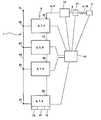
- FIG. 1shows a schematic circuit diagram of an embodiment of the universal power supply system 1 according to the present invention.
- This universal power supply systemcomprises a 380 V three-phase AC power source 3 .
- the AC voltageis adapted to be transmitted to an AC/DC converter 5 via a line 24 .
- This AC/DC converter 5is composed of a plurality of AC/DC converter components 6 which are connected in parallel to the line 24 via respective input terminals 23 .
- the AC/DC converter components 6are defined by a switched mode power supply 7 and, in particular, by a flyback converter 8 clocked on the primary side and acting as a switched mode power supply 7 .
- the various converter components 6are serially connected to one another via respective output terminals 22 and they are connected to a coaxial cable 15 acting as a cable connection 4 .
- an electric consumer 2Via said cable connection 4 , an electric consumer 2 has electric power supplied thereto.
- a means for coupling data signals in/out 13is additionally connected to the cable connection 4 .
- Said means for coupling data signals in/out 13is used for feeding in respective data signals or for coupling out data signals that have been received from the electric consumer 2 or from units associated therewith.
- a filter means 12can be arranged between the AC/DC converter 5 and the electric consumer 2 so that, if necessary, the DC voltage generated by the AC/DC converter 5 can be smoothed still further.
- the transmission of the data signalsis also effected via the cable connection 4 implemented as a coaxial cable 15 .
- FIG. 1only one electric consumer 2 is shown.
- a plurality of electric consumershas supplied thereto electric power and also data via the cable connection 4 from the universal power supply system 1 according to the present invention.
- Such electric consumersare e.g. actuators located at sites which are far away and/or not easily accessible.
- the actuatorscontrol e.g. units of fluid lines, such as valves, shut-off devices, restrictors, pumps and the like, so that the flow of fluid into and along the fluid line is controlled and shut off in emergency cases, such as leakage, line fractures or the like, and so that also parameters of the fluid, of the fluid flow or of the respective units are monitored and controlled.
- the fluidis normally fed into the lines under high pressure from a respective fluid source and conducted along said lines e.g. from the bottom to the surface of the sea. Since such a fluid normally contains aggressive or environmentally noxious components, a power supply and remote control which can be effected with the aid of the universal power supply system 1 according to the present invention will be of great advantage.
- the remote control of the respective actuatorscan in this connection be carried out via the communication connection established with the aid of the means for coupling data signals in/out 13 .
- All the units of the universal power supply system 1including, if desired, the electric consumer 2 , are adapted to be controlled and/or regulated by a controller 14 .
- a relevant monitoring of parameters of the various unitscan be carried out.
- the controller 14is connected to the various units via connections represented by broken lines, so as to control, regulate and/or monitor said units.
- the switched mode power supplies 7 and flyback converters 8can be implemented as integrated circuits. These integrated circuits directly comprise respective further units, such as power factor control means 16 , undervoltage detection means 17 or overvoltage monitoring means 18 . In order to simplify matters, these additional units are shown in FIG. 1 only in the case of one flyback converter 8 ; normally, they are, however, component parts of all flyback converters.
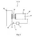
- FIG. 2shows a simplified embodiment for a flyback converter 8 acting as a switched mode power supply 7 .
- the flyback converter 8comprises a transmitter 19 consisting of a primary winding connected to the input terminal 23 and of a secondary winding connected to the output terminal 22 . An effective magnetic coupling exists between these two windings.
- the transmitteracts as a magnetic energy storage.
- a switching means 9 in the form of a power transistor 10When a switching means 9 in the form of a power transistor 10 is closed, the current will increase in the primary winding and energy will be stored in the transmitter.
- the switching means 9is opened, the stored energy on the side of the secondary winding will be supplied to a smoothing capacitor 21 via a diode 20 .
- the stored energyis fed in, in the form of an AC voltage, via the output terminal 22 .
- the respective flyback convertershave their output terminals 22 serially connected to the cable connection 4 , cf. FIG. 1 .
- a pulse width modulation means 11is provided in the flyback converter 8 .
- Said pulse width modulation means 11produces a pulse width-modulated signal whose clock cycle ratio is controlled in accordance with the measured actual value of the output voltage.
- the actual value measured at the output of the flyback converteris subtracted from the respective desired value and this difference is supplied, via a control amplifier of the flyback converter, to the pulse width modulation means 11 .
- the output voltage of the control amplifieris compared with a sawtooth voltage whose frequency determines the clock frequency of the flyback converter. Depending on the result of this comparison, the switching means 9 is switched on or off and the desired output voltage is adjusted in this way.
- each of the flyback converters 8there are integrated circuits, which can be associated with or included in each of the flyback converters 8 according to FIG. 1 .
- These integrated circuitsalso comprise the protection circuits, e.g. undervoltage detection means, overcurrent monitoring means, soft starting means and the like, which are required for operating the flyback converter.
Landscapes
- Engineering & Computer Science (AREA)
- Power Engineering (AREA)
- Dc-Dc Converters (AREA)
- Rectifiers (AREA)
- Supply And Distribution Of Alternating Current (AREA)
- Direct Current Feeding And Distribution (AREA)
- Ac-Ac Conversion (AREA)
- Laying Of Electric Cables Or Lines Outside (AREA)
- Earth Drilling (AREA)
- Catching Or Destruction (AREA)
Abstract
Description
Claims (19)
Priority Applications (1)
| Application Number | Priority Date | Filing Date | Title |
|---|---|---|---|
| US13/338,837US8492927B2 (en) | 2001-09-19 | 2011-12-28 | Universal power supply system |
Applications Claiming Priority (6)
| Application Number | Priority Date | Filing Date | Title |
|---|---|---|---|
| DE20115471.4 | 2001-09-19 | ||
| DE20115471UDE20115471U1 (en) | 2001-09-19 | 2001-09-19 | Universal energy supply system |
| DE20115471U | 2001-09-19 | ||
| PCT/EP2002/010471WO2003026112A2 (en) | 2001-09-19 | 2002-09-18 | Universal power supply system |
| US10/489,573US8106536B2 (en) | 2001-09-19 | 2002-09-18 | Universal power supply system |
| US13/338,837US8492927B2 (en) | 2001-09-19 | 2011-12-28 | Universal power supply system |
Related Parent Applications (3)
| Application Number | Title | Priority Date | Filing Date |
|---|---|---|---|
| US10489573Division | |||
| US10/489,573DivisionUS8106536B2 (en) | 2001-05-07 | 2002-09-18 | Universal power supply system |
| PCT/EP2002/010471DivisionWO2003026112A2 (en) | 2001-05-07 | 2002-09-18 | Universal power supply system |
Publications (2)
| Publication Number | Publication Date |
|---|---|
| US20120169119A1 US20120169119A1 (en) | 2012-07-05 |
| US8492927B2true US8492927B2 (en) | 2013-07-23 |
Family
ID=7961907
Family Applications (2)
| Application Number | Title | Priority Date | Filing Date |
|---|---|---|---|
| US10/489,573Active2025-12-30US8106536B2 (en) | 2001-05-07 | 2002-09-18 | Universal power supply system |
| US13/338,837Expired - Fee RelatedUS8492927B2 (en) | 2001-09-19 | 2011-12-28 | Universal power supply system |
Family Applications Before (1)
| Application Number | Title | Priority Date | Filing Date |
|---|---|---|---|
| US10/489,573Active2025-12-30US8106536B2 (en) | 2001-05-07 | 2002-09-18 | Universal power supply system |
Country Status (7)
| Country | Link |
|---|---|
| US (2) | US8106536B2 (en) |
| AU (1) | AU2002350450A1 (en) |
| BR (1) | BRPI0212663B1 (en) |
| DE (1) | DE20115471U1 (en) |
| GB (3) | GB2396492B (en) |
| NO (1) | NO328254B1 (en) |
| WO (1) | WO2003026112A2 (en) |
Families Citing this family (15)
| Publication number | Priority date | Publication date | Assignee | Title |
|---|---|---|---|---|
| DE20115471U1 (en) | 2001-09-19 | 2003-02-20 | Biester, Klaus, 29342 Wienhausen | Universal energy supply system |
| DE20018560U1 (en)* | 2000-10-30 | 2002-03-21 | CAMERON GmbH, 29227 Celle | Control and supply system |
| DE20115473U1 (en)* | 2001-09-19 | 2003-02-20 | Biester, Klaus, 29342 Wienhausen | Universal energy supply system |
| US7615893B2 (en)* | 2000-05-11 | 2009-11-10 | Cameron International Corporation | Electric control and supply system |
| DE20115474U1 (en)* | 2001-09-19 | 2003-02-20 | Biester, Klaus, 29342 Wienhausen | DC converter device |
| US7020271B2 (en)* | 2003-06-12 | 2006-03-28 | Barbara Isabel Hummel | Ring control device |
| DE20115475U1 (en)* | 2001-09-19 | 2003-02-20 | Biester, Klaus, 29342 Wienhausen | DC converter device |
| NO332768B1 (en)* | 2009-12-16 | 2013-01-14 | Smartmotor As | System for operation of elongated electric machines |
| US8373307B2 (en) | 2011-05-26 | 2013-02-12 | General Electric Company | Methods and systems for direct current power transmission |
| FR2982092B1 (en)* | 2011-11-02 | 2015-01-02 | Valeo Systemes De Controle Moteur | POWER MODULE AND ELECTRIC DEVICE FOR POWER SUPPLY AND CHARGING COMBINED WITH ACCUMULATOR AND MOTOR |
| US9143029B2 (en) | 2011-12-15 | 2015-09-22 | General Electric Company | System and method for power distribution |
| TWI581668B (en)* | 2011-12-20 | 2017-05-01 | Panasonic Corp | Microwave heating device |
| CN105006472B (en)* | 2015-07-28 | 2018-01-23 | 许继电气股份有限公司 | Compression joint type power model valve section |
| US11291088B2 (en)* | 2016-06-27 | 2022-03-29 | Sharp Kabushiki Kaisha | High-frequency heating device |
| GB2599448A (en)* | 2020-10-05 | 2022-04-06 | Illinois Tool Works | Material testing system |
Citations (170)
| Publication number | Priority date | Publication date | Assignee | Title |
|---|---|---|---|---|
| DE492021C (en) | 1926-04-13 | 1930-02-15 | Amalgamated Carburetters Ltd | Actuating device for Bowden cables |
| DE524986C (en) | 1926-05-27 | 1931-05-18 | Titanium Alloy Mfg Company | Process for the extraction of zirconium salts from silicon-containing zirconium ores |
| US1979425A (en) | 1931-08-12 | 1934-11-06 | Gen Ind Co | Tandem motor mechanism |
| US2119534A (en) | 1936-09-11 | 1938-06-07 | Gerber Lee | Valve |
| US2387800A (en) | 1944-07-19 | 1945-10-30 | Gen Motors Corp | Actuator |
| GB625580A (en) | 1945-10-25 | 1949-06-30 | Charles Somville | Automatic regulation device for transmission mechanisms, specially for brake control |
| US2645450A (en) | 1948-11-26 | 1953-07-14 | C B Hunt & Son Inc | Fluid valve means |
| US2953344A (en) | 1956-11-02 | 1960-09-20 | John R Yancey | Valve actuating mechanism |
| US3089509A (en) | 1959-03-04 | 1963-05-14 | Int Basic Economy Corp | Three-way valve and sleeve seat |
| FR1390757A (en) | 1963-04-30 | 1965-02-26 | Sulzer Ag | Electric servo-motor valve |
| GB1001629A (en) | 1963-03-18 | 1965-08-18 | Rotork Eng Co Ltd | Improvements in or relating to actuating mechanisms, more particularly for fluid flow control valves |
| DE1199088B (en) | 1963-05-10 | 1965-08-19 | Doering G M B H | Actuator for the spindle of gate valves, flap valves or the like. |
| US3275737A (en) | 1964-04-15 | 1966-09-27 | James M Caller | Coaxial cable terminating means |
| US3324741A (en) | 1965-06-15 | 1967-06-13 | Acf Ind Inc | Valve operator |
| US3353594A (en) | 1963-10-14 | 1967-11-21 | Hydril Co | Underwater control system |
| US3429341A (en) | 1965-05-07 | 1969-02-25 | Hoerbiger Ventilwerke Ag | Control slide valve |
| US3452776A (en) | 1967-07-14 | 1969-07-01 | Baker Oil Tools Inc | Pressure control valve |
| DE1525323A1 (en) | 1966-03-08 | 1969-09-18 | Leipziger Buchbindereimaschine | Release device for handwheels |
| US3738183A (en) | 1971-02-01 | 1973-06-12 | Philadelphia Gear Corp | Combination drive for valve operator |
| US3771918A (en) | 1972-07-24 | 1973-11-13 | A Winter | Linear positive displacement pump with rotary to reciprocating drive |
| US3782653A (en) | 1971-03-20 | 1974-01-01 | Masson Scott Thrissell Eng Ltd | Web tension control apparatus |
| US3818307A (en) | 1972-07-31 | 1974-06-18 | Bell Telephone Labor Inc | Serially-connected converters having multiple regulation modes for use in supplying serially-connected loads on long lines |
| US3865142A (en) | 1970-05-19 | 1975-02-11 | Fmc Corp | Electric remote control system for underwater wells |
| US3887898A (en) | 1973-08-20 | 1975-06-03 | Texaco Inc | Well logging system using 3 phase AC power supply |
| US3980808A (en) | 1974-09-19 | 1976-09-14 | The Furukawa Electric Co., Ltd. | Electric cable |
| FR2309748A1 (en) | 1974-08-14 | 1976-11-26 | Coureau Jean Claude | Electrically:operated sliding mechanism - has heater causing expansion of fluid in variable:volume chamber |
| US4062057A (en) | 1977-04-15 | 1977-12-06 | The United States Of America As Represented By The Secretary Of The Navy | Regulated power supply having a series arrangement of inverters |
| FR2353992A1 (en) | 1976-06-04 | 1977-12-30 | Bbc Brown Boveri & Cie | DC HV step:up transformer for charging battery - uses transistor switches and transformers to handle inputs of several kV. |
| US4124884A (en) | 1977-03-07 | 1978-11-07 | Bell Telephone Laboratories, Incorporated | DC to DC converter with regulated input impedance |
| US4179944A (en) | 1977-06-27 | 1979-12-25 | United Technologies Corporation | Fail safe redundant actuator |
| US4256065A (en) | 1977-12-08 | 1981-03-17 | Maschinenfabrik Augsburg-Nurnberg Aktiengesellschaft | Arrangement for the controllable operation of valves |
| EP0028296A2 (en) | 1979-10-31 | 1981-05-13 | Licentia Patent-Verwaltungs-GmbH | Arrangement for power-supply and measurement-data transmission from a central station to several measurement posts |
| US4290101A (en) | 1977-12-29 | 1981-09-15 | Burroughs Corporation | N Phase digital inverter |
| US4295552A (en) | 1977-07-15 | 1981-10-20 | Sulzer Brothers Limited | Means for coupling a hand drive with a rotatable shaft |
| US4309734A (en) | 1979-11-05 | 1982-01-05 | Trw Inc. | Methods and apparatus for limiting electrical current to a subsea petroleum installation |
| EP0050466A1 (en) | 1980-10-22 | 1982-04-28 | The Duriron Company, Inc. | Rotary valve actuator |
| US4346728A (en) | 1980-07-28 | 1982-08-31 | Anchor/Darling Industries, Inc. | Automated dual mode valve actuator |
| US4350322A (en) | 1981-08-31 | 1982-09-21 | Grove Truseal Valve Company | High torque plug valve actuator |
| US4363975A (en) | 1980-05-30 | 1982-12-14 | Saskatchewan Power Corporation | Direct current power supply |
| DE3224041A1 (en) | 1981-09-08 | 1983-03-24 | Veb Pentacon Dresden Kamera- Und Kinowerke, Ddr 8021 Dresden | Locking device for a camera tensioner |
| US4378848A (en) | 1979-10-02 | 1983-04-05 | Fmc Corporation | Method and apparatus for controlling subsea well template production systems |
| US4423747A (en) | 1980-09-16 | 1984-01-03 | Robert Bosch Gmbh | Pressure regulating valve |
| US4436280A (en) | 1982-09-30 | 1984-03-13 | Daniel Industries, Inc. | Valve actuator mechanism for lift-turn type valves |
| DE3303248A1 (en) | 1983-02-01 | 1984-08-16 | Robert Bosch Gmbh, 7000 Stuttgart | Semiconductor circuit corresponding to a higher-power Z diode |
| DE3316258A1 (en) | 1983-05-04 | 1984-11-08 | Licentia Patent-Verwaltungs-Gmbh, 6000 Frankfurt | Electrochemical pressure transducer |
| GB2141882A (en) | 1983-06-16 | 1985-01-03 | Kabel & Gummiwerke Ag | Co-axial cable plugs and sockets |
| US4500832A (en) | 1983-02-28 | 1985-02-19 | Codman & Shurtleff, Inc. | Electrical transformer |
| US4521642A (en) | 1980-06-05 | 1985-06-04 | Les Cables De Lyon | Sealed connection connecting an undersea coaxial cable to a repeater and a method of making same |
| US4533987A (en) | 1981-11-11 | 1985-08-06 | Matsushita Electric Works, Ltd. | Power supply system |
| US4548383A (en) | 1983-03-03 | 1985-10-22 | Mannesmann Rexroth Gmbh | Electrically controlled pressure reducing valve |
| DE3417455A1 (en) | 1984-05-11 | 1985-11-14 | Licentia Patent-Verwaltungs-Gmbh, 6000 Frankfurt | INDUCTIVE ENERGY AND DATA TRANSFER |
| DE3424041A1 (en) | 1984-06-29 | 1986-01-02 | Siemens AG, 1000 Berlin und 8000 München | Circuit arrangement for current limiting in a DC/DC converter |
| US4565213A (en) | 1980-10-28 | 1986-01-21 | Bernhardt & Frederick Co., Inc. | Ball valve device with hold-open tube |
| US4617501A (en) | 1985-09-19 | 1986-10-14 | John D. Gieser | Control and safety system for electrically powered submersible tools and lights |
| SU1270293A1 (en) | 1985-03-12 | 1986-11-15 | Волгоградский завод буровой техники | Control system for blowout-preventing equipment |
| US4639714A (en) | 1984-12-21 | 1987-01-27 | Ferranti Subsea Systems, Ltd. | Combined power and control signal transmission system |
| US4725039A (en) | 1987-03-17 | 1988-02-16 | Clevite Industries, Inc. | Self-pressure regulating proportional valve |
| US4745815A (en) | 1986-12-08 | 1988-05-24 | Sundstrand Corporation | Non-jamming screw actuator system |
| US4771982A (en) | 1986-05-14 | 1988-09-20 | Chevron Research Company | Slidable electric valve device having a spring |
| US4788448A (en) | 1984-12-06 | 1988-11-29 | Ferranti Subsea Systems, Ltd. | Power transfer of direct current with inductive couplings |
| EP0303801A1 (en) | 1987-08-10 | 1989-02-22 | Siemens Aktiengesellschaft | Valve |
| US4814965A (en) | 1987-09-30 | 1989-03-21 | Spectra Physics | High power flyback, variable output voltage, variable input voltage, decoupled power supply |
| US4814963A (en) | 1987-09-30 | 1989-03-21 | Spectra Physics | Modular power supply with variable input voltage and output voltage flyback power modules |
| US4844554A (en) | 1988-05-26 | 1989-07-04 | General Signal Corporation | Empty-load valve device |
| DE3832304A1 (en) | 1988-09-20 | 1990-03-29 | Haberecht Helga | Actuating drive |
| US4920811A (en) | 1988-03-10 | 1990-05-01 | The British Petroleum Company P.L.C. | Fail-safe release actuator mechanism |
| EP0384607A2 (en) | 1989-02-22 | 1990-08-29 | Cooper Cameron Corporation | Actuated gate valve with manual override |
| DE9005411U1 (en) | 1989-11-24 | 1990-08-30 | Thomas Technik KG Gesellschaft für Magnet- und Verfahrenstechnik, 5243 Herdorf | Magnetically operated valve |
| US5031088A (en) | 1989-03-31 | 1991-07-09 | Kabushiki Kaisha Toshiba | Variable-voltage and variable-frequency power converter |
| US5038622A (en) | 1989-12-22 | 1991-08-13 | Tijmann Willem B | Strain gage assembly for measuring excessive tensile strain of a flexible elongated member, such as a steel structural cable, or an electrical transmission cable, or a glass fiber optic communication cable, which may slightly twist under tensile strain |
| US5055991A (en) | 1990-10-12 | 1991-10-08 | Compaq Computer Corporation | Lossless snubber |
| SU1709511A1 (en) | 1989-12-26 | 1992-01-30 | Центральное научно-производственное объединение "Ленинец" | High voltage switch |
| US5105351A (en) | 1989-06-30 | 1992-04-14 | Kabushiki Kaisha Toshiba | X-ray power supply with plural frequency converters |
| US5138249A (en) | 1990-06-08 | 1992-08-11 | Alcatel Espace | Circuit for regulating a parameter by means of a bidirectional current structure |
| US5168422A (en) | 1989-09-08 | 1992-12-01 | Allanson, Division Of Jannock Limited | Self-enclosed neon transformer |
| US5195721A (en) | 1990-05-04 | 1993-03-23 | Ava International Corporation | Fail safe valve actuator |
| US5210519A (en) | 1990-06-22 | 1993-05-11 | British Aerospace Public Limited Company | Digital data transmission |
| US5230033A (en) | 1984-11-01 | 1993-07-20 | Optelecom, Inc. | Subminiature fiber optic submarine cable and method of making |
| GB2266942A (en) | 1990-05-04 | 1993-11-17 | Ava Int Corp | Fail-safe valve actuator |
| US5285563A (en) | 1991-01-11 | 1994-02-15 | Rotelec | Method of making a static electromagnetic inductor |
| US5297015A (en) | 1989-07-21 | 1994-03-22 | Hitachi, Ltd. | Power supply control system |
| US5301096A (en) | 1991-09-27 | 1994-04-05 | Electric Power Research Institute | Submersible contactless power delivery system |
| US5311419A (en) | 1992-08-17 | 1994-05-10 | Sundstrand Corporation | Polyphase AC/DC converter |
| EP0622574A2 (en) | 1993-04-27 | 1994-11-02 | EGMO Ltd. | Actuating device for a rotatable valve shut-off element |
| EP0626670A1 (en) | 1993-05-28 | 1994-11-30 | Koninklijke Philips Electronics N.V. | Selection driver comprising integrated driver circuits for a multi-beam flat display device |
| US5418707A (en) | 1992-04-13 | 1995-05-23 | The United States Of America As Represented By The United States Department Of Energy | High voltage dc-dc converter with dynamic voltage regulation and decoupling during load-generated arcs |
| DE4344709A1 (en) | 1993-12-27 | 1995-06-29 | Daimler Benz Ag | Conversion of different amplitude DC and AC voltages |
| US5433245A (en) | 1993-08-16 | 1995-07-18 | Westinghouse Electric Corporation | Online valve diagnostic monitoring system having diagnostic couplings |
| WO1995020836A1 (en) | 1994-01-26 | 1995-08-03 | Onan Corporation | Generator power system and method |
| DE4414677A1 (en) | 1994-04-27 | 1995-11-02 | Pintsch Bamag Ag | High voltage DC-DC converter |
| US5489897A (en) | 1992-04-15 | 1996-02-06 | Fujitsu Limited | Power control monitoring system for underwater cable communications systems |
| US5508903A (en) | 1995-04-21 | 1996-04-16 | Alexndrov; Felix | Interleaved DC to DC flyback converters with reduced current and voltage stresses |
| DE4447395A1 (en) | 1994-12-23 | 1996-06-27 | Mannesmann Ag | Actuator |
| WO1996028878A1 (en) | 1995-03-09 | 1996-09-19 | Rca Thomson Licensing Corporation | Switched-mode power supply with synchronous preconverter |
| US5563780A (en) | 1993-12-08 | 1996-10-08 | International Power Systems, Inc. | Power conversion array applying small sequentially switched converters in parallel |
| US5572182A (en) | 1993-02-17 | 1996-11-05 | Petrolew Brasileiro S.A. - Petrobras | Integrated power and signal transmission system |
| US5573032A (en) | 1993-08-25 | 1996-11-12 | Rosemount Inc. | Valve positioner with pressure feedback, dynamic correction and diagnostics |
| DE19528081A1 (en) | 1995-07-31 | 1997-02-06 | Wolfgang Dr Ing Nestler | Pivot drive for converting original linear lift movement into rotary movement with limited rotary angle - has second axis with angular clearance at right angle and crossways to lift axis |
| US5629844A (en) | 1995-04-05 | 1997-05-13 | International Power Group, Inc. | High voltage power supply having multiple high voltage generators |
| DE19548593A1 (en) | 1995-12-23 | 1997-07-10 | Behr Gmbh & Co | Mechanism for conversion of rotation to translation and vice-versa |
| US5649451A (en) | 1994-06-30 | 1997-07-22 | Ruland; Frederick W. | Compact mechanism for creating simultaneous rotary and linear motion |
| WO1997038479A1 (en) | 1996-04-04 | 1997-10-16 | The Council For The Central Laboratory Of The Research Councils | Dc power converter |
| DE19614627A1 (en) | 1996-04-13 | 1997-10-16 | Abb Patent Gmbh | High voltage converter system |
| US5731969A (en) | 1996-07-29 | 1998-03-24 | Small; Kenneth T. | Three-phase AC power converter with power factor correction |
| US5754028A (en) | 1995-06-16 | 1998-05-19 | Smh Management Services Ag | Charger for electrical energy accumulator |
| DE19639476C1 (en) | 1996-09-26 | 1998-05-20 | Wolfgang Heyng | Manually-operated rotary control grip e.g. for motorcycle or snowmobile |
| US5768117A (en) | 1993-12-27 | 1998-06-16 | Hitachi, Ltd. | Power supply system for supplying electric power to a load through plural converters |
| WO1998030816A1 (en) | 1996-12-23 | 1998-07-16 | Linak A/S | Linear actuator |
| US5806761A (en) | 1992-12-25 | 1998-09-15 | Toto Ltd. | Combination faucet device |
| US5811889A (en) | 1996-03-11 | 1998-09-22 | Intel Corporation | Method and apparatus for redundancy circuits using power fets |
| DE19714552A1 (en) | 1997-04-09 | 1998-10-15 | Knick Elektronische Mesgeraete | Circuit arrangement for multiplying a current signal |
| US5832996A (en) | 1996-02-15 | 1998-11-10 | Baker Hughes Incorporated | Electro hydraulic downhole control device |
| DE19750041C1 (en) | 1997-11-12 | 1999-01-21 | Sma Regelsysteme Gmbh | Semiconductor DC voltage regulator |
| GB2332220A (en) | 1997-12-10 | 1999-06-16 | Abb Seatec Ltd | Underwater hydrocarbon production systems |
| US5923550A (en) | 1996-05-01 | 1999-07-13 | General Electric Company | Interference reduction by harmonic phase shift in multiple PWM rectifier operation |
| WO1999037009A1 (en) | 1997-01-13 | 1999-07-22 | Pes, Inc. | Downhole power transmission system |
| US5930340A (en) | 1997-07-07 | 1999-07-27 | Advanced Micro Devices | Device and method for isolating voice and data signals on a common carrier |
| US5982645A (en) | 1992-08-25 | 1999-11-09 | Square D Company | Power conversion and distribution system |
| US5983743A (en) | 1997-04-03 | 1999-11-16 | Dresser Industries, Inc. | Actuator assembly |
| US5984260A (en) | 1996-10-15 | 1999-11-16 | Baker Hughes Incorporated | Electrically driven actuator with failsafe feature |
| US6007047A (en) | 1998-06-05 | 1999-12-28 | Phipps; Jack M. | Rotary actuator for stem valves |
| US6031743A (en) | 1998-10-28 | 2000-02-29 | International Business Machines Corporation | Fault isolation in a redundant power converter |
| US6032924A (en) | 1999-01-22 | 2000-03-07 | Sparco Inc. | Motorized valve actuating device |
| US6041667A (en) | 1997-07-31 | 2000-03-28 | Fev Motorentechnik Gmbh & Co. Kg | Method of operating an electromagnetic actuator with consideration of the armature motion |
| US6069802A (en)* | 1998-07-31 | 2000-05-30 | Priegnitz; Robert A. | Transformer isolated driver and isolated forward converter |
| US6073907A (en) | 1997-11-07 | 2000-06-13 | Erie Manufacturing Company | Removable and interchangeable valve actuator system |
| JP3065054B2 (en) | 1998-02-11 | 2000-07-12 | バイエリッシェ モートーレン ウエルケ アクチエンゲゼルシャフト | Driving device for traveling vehicle transmission |
| US6094366A (en) | 1998-01-05 | 2000-07-25 | Kalfhaus; Reinhard | Current-to-voltage converter and associate closed-loop control circuit |
| US6095487A (en) | 1999-03-12 | 2000-08-01 | Electrowatt Technology Innovation Ag | Drive arrangement for an actuator |
| EP1024422A1 (en) | 1999-01-27 | 2000-08-02 | Cooper Cameron Corporation | Electric Actuator |
| DE19909712A1 (en) | 1999-03-05 | 2000-09-07 | Linde Ag | Control valve and actuator are linked by rocker and cam-operated slide using drive gearing to complete two-way slide movement. |
| US6142171A (en) | 1997-04-07 | 2000-11-07 | Hancock; Leonard H. | Valve adapter |
| US6152167A (en) | 1999-02-11 | 2000-11-28 | Cooper Cameron | Valve actuator with emergency shutdown feature |
| US6154381A (en) | 1999-06-30 | 2000-11-28 | General Motors Corporation | High efficiency power system with plural parallel DC/DC converters |
| US6181576B1 (en) | 1999-04-09 | 2001-01-30 | Sansha Electric Manufacturing Company Limited | Power supply apparatus for arc-utilizing apparatuses |
| WO2001037411A2 (en) | 1999-11-19 | 2001-05-25 | Iwatt | Isolated power converter having primary feedback control |
| EP1107437A2 (en) | 1999-12-01 | 2001-06-13 | Hewlett-Packard Company, A Delaware Corporation | Power supply |
| DE19963105A1 (en) | 1999-12-24 | 2001-06-28 | Daimler Chrysler Ag | Driving a bridging switch for current converter circuit with partial current converter systems e.g. for rail vehicles, involves connecting or decoupling partial current converter systems for certain operating situations |
| WO2001052397A1 (en) | 2000-01-10 | 2001-07-19 | Bartronics Inc. | Method and apparatus for stabilization and minimization of losses of a series connection of dc/dc-converters connected to the output-side partial voltages of a three-level pwm rectifier system |
| US6269015B1 (en) | 2000-11-08 | 2001-07-31 | Sansha Electric Manufacturing Company, Limited | Power supply apparatus for ARC-utilizing apparatuses |
| WO2001084689A1 (en) | 2000-04-28 | 2001-11-08 | Aker Engineering As | Distribution system for electrical power |
| US6329726B1 (en) | 2000-03-03 | 2001-12-11 | Broadband Telcom Power, Inc. | Proportional distribution of power from a plurality of power sources |
| US6356384B1 (en) | 1998-03-24 | 2002-03-12 | Xtera Communications Inc. | Broadband amplifier and communication system |
| US6373726B1 (en)* | 1999-01-28 | 2002-04-16 | Power-One A.G. | Flyback converter with transistorized rectifier controlled by primary side control logic |
| US6385057B1 (en) | 2001-01-31 | 2002-05-07 | Bartronics, Inc. | Power conversion system and method of power conversion |
| US6388904B2 (en) | 1998-01-30 | 2002-05-14 | Kabushiki Kaisha Toshiba | Power supply device for electromotive railcar |
| US6407987B1 (en) | 1989-04-28 | 2002-06-18 | Wire21, Inc. | Transformer coupler for communication over various lines |
| US6411527B1 (en) | 2000-08-09 | 2002-06-25 | Abb Patent Gmbh | High-voltage DC/DC converter |
| US6438005B1 (en) | 2000-11-22 | 2002-08-20 | Linear Technology Corporation | High-efficiency, low noise, inductorless step-down DC/DC converter |
| US6446660B1 (en) | 1999-06-29 | 2002-09-10 | Ampo, S. Coop. | Valve assembly with multiple mode actuators |
| EP1244203A2 (en) | 2001-03-22 | 2002-09-25 | SEMIKRON Elektronik GmbH | Power converter circuit for generators with dynamically varying outputpower |
| US6494294B1 (en) | 2000-01-12 | 2002-12-17 | Mikuni Adec Corporation | Lubricating oil supplying device |
| US6494257B2 (en) | 2000-03-24 | 2002-12-17 | Fmc Technologies, Inc. | Flow completion system |
| US6529120B1 (en) | 1999-03-25 | 2003-03-04 | Intech 21, Inc. | System for communicating over a transmission line |
| US6559385B1 (en) | 2000-07-14 | 2003-05-06 | 3M Innovative Properties Company | Stranded cable and method of making |
| US6595487B2 (en) | 2000-05-16 | 2003-07-22 | Kongsberg Offshore A/S | Electric actuator |
| US6615916B1 (en) | 1999-02-05 | 2003-09-09 | Schlumberger Technology Corporation | Method of saving string of tools installed in an oil well and a corresponding transmission assembly |
| US6659200B1 (en) | 1999-12-20 | 2003-12-09 | Halliburton Energy Services, Inc. | Actuator assembly and method for actuating downhole assembly |
| US6668639B2 (en) | 2000-02-28 | 2003-12-30 | Delphi Technologies, Inc. | Plunger assembly having a preset spring force pre-load |
| US6741162B1 (en) | 2000-10-04 | 2004-05-25 | Conexant Systems, Inc. | Power line networking apparatus and method |
| US6937923B1 (en) | 2000-11-01 | 2005-08-30 | Weatherford/Lamb, Inc. | Controller system for downhole applications |
| US6965302B2 (en) | 2000-04-14 | 2005-11-15 | Current Technologies, Llc | Power line communication system and method of using the same |
| US6998962B2 (en) | 2000-04-14 | 2006-02-14 | Current Technologies, Llc | Power line communication apparatus and method of using the same |
| US7075414B2 (en) | 2003-05-13 | 2006-07-11 | Current Technologies, Llc | Device and method for communicating data signals through multiple power line conductors |
| US7264057B2 (en) | 2000-08-14 | 2007-09-04 | Schlumberger Technology Corporation | Subsea intervention |
| US7433214B2 (en) | 2001-09-19 | 2008-10-07 | Cameron International Corporation | DC converter |
| JP4200270B2 (en) | 2002-05-30 | 2008-12-24 | パナソニック株式会社 | Light amount adjustment device, lens barrel, imaging device |
| JP3150068U (en) | 2009-01-23 | 2009-04-30 | 村上 昭雄 | Wireless wake-up oscillator. |
| US7615893B2 (en) | 2000-05-11 | 2009-11-10 | Cameron International Corporation | Electric control and supply system |
| US8106536B2 (en) | 2001-09-19 | 2012-01-31 | Cameron International Corporation | Universal power supply system |
Family Cites Families (1)
| Publication number | Priority date | Publication date | Assignee | Title |
|---|---|---|---|---|
| DD145982B1 (en) | 1979-10-01 | 1982-09-29 | Lothar Friedrich | CIRCUIT ARRANGEMENT FOR POWER SUPPLY OF THE CONTROL ELECTRONICS OF FORCED COMBUSED CIRCUIT BREAKERS |
- 2001
- 2001-09-19DEDE20115471Upatent/DE20115471U1/ennot_activeExpired - Lifetime
- 2002
- 2002-09-18WOPCT/EP2002/010471patent/WO2003026112A2/ennot_activeApplication Discontinuation
- 2002-09-18BRBRPI0212663-0Apatent/BRPI0212663B1/ennot_activeIP Right Cessation
- 2002-09-18USUS10/489,573patent/US8106536B2/enactiveActive
- 2002-09-18GBGB0408686Apatent/GB2396492B/ennot_activeExpired - Fee Related
- 2002-09-18GBGB0603268Apatent/GB2420233B/ennot_activeExpired - Fee Related
- 2002-09-18GBGB0603309Apatent/GB2420026B/ennot_activeExpired - Fee Related
- 2002-09-18AUAU2002350450Apatent/AU2002350450A1/ennot_activeAbandoned
- 2004
- 2004-03-18NONO20041129Apatent/NO328254B1/ennot_activeIP Right Cessation
- 2011
- 2011-12-28USUS13/338,837patent/US8492927B2/ennot_activeExpired - Fee Related
Patent Citations (175)
| Publication number | Priority date | Publication date | Assignee | Title |
|---|---|---|---|---|
| DE492021C (en) | 1926-04-13 | 1930-02-15 | Amalgamated Carburetters Ltd | Actuating device for Bowden cables |
| DE524986C (en) | 1926-05-27 | 1931-05-18 | Titanium Alloy Mfg Company | Process for the extraction of zirconium salts from silicon-containing zirconium ores |
| US1979425A (en) | 1931-08-12 | 1934-11-06 | Gen Ind Co | Tandem motor mechanism |
| US2119534A (en) | 1936-09-11 | 1938-06-07 | Gerber Lee | Valve |
| US2387800A (en) | 1944-07-19 | 1945-10-30 | Gen Motors Corp | Actuator |
| GB625580A (en) | 1945-10-25 | 1949-06-30 | Charles Somville | Automatic regulation device for transmission mechanisms, specially for brake control |
| US2645450A (en) | 1948-11-26 | 1953-07-14 | C B Hunt & Son Inc | Fluid valve means |
| US2953344A (en) | 1956-11-02 | 1960-09-20 | John R Yancey | Valve actuating mechanism |
| US3089509A (en) | 1959-03-04 | 1963-05-14 | Int Basic Economy Corp | Three-way valve and sleeve seat |
| GB1001629A (en) | 1963-03-18 | 1965-08-18 | Rotork Eng Co Ltd | Improvements in or relating to actuating mechanisms, more particularly for fluid flow control valves |
| FR1390757A (en) | 1963-04-30 | 1965-02-26 | Sulzer Ag | Electric servo-motor valve |
| DE1199088B (en) | 1963-05-10 | 1965-08-19 | Doering G M B H | Actuator for the spindle of gate valves, flap valves or the like. |
| US3353594A (en) | 1963-10-14 | 1967-11-21 | Hydril Co | Underwater control system |
| US3275737A (en) | 1964-04-15 | 1966-09-27 | James M Caller | Coaxial cable terminating means |
| US3429341A (en) | 1965-05-07 | 1969-02-25 | Hoerbiger Ventilwerke Ag | Control slide valve |
| US3324741A (en) | 1965-06-15 | 1967-06-13 | Acf Ind Inc | Valve operator |
| DE1525323A1 (en) | 1966-03-08 | 1969-09-18 | Leipziger Buchbindereimaschine | Release device for handwheels |
| US3452776A (en) | 1967-07-14 | 1969-07-01 | Baker Oil Tools Inc | Pressure control valve |
| US3865142A (en) | 1970-05-19 | 1975-02-11 | Fmc Corp | Electric remote control system for underwater wells |
| US3738183A (en) | 1971-02-01 | 1973-06-12 | Philadelphia Gear Corp | Combination drive for valve operator |
| US3782653A (en) | 1971-03-20 | 1974-01-01 | Masson Scott Thrissell Eng Ltd | Web tension control apparatus |
| US3771918A (en) | 1972-07-24 | 1973-11-13 | A Winter | Linear positive displacement pump with rotary to reciprocating drive |
| US3818307A (en) | 1972-07-31 | 1974-06-18 | Bell Telephone Labor Inc | Serially-connected converters having multiple regulation modes for use in supplying serially-connected loads on long lines |
| US3887898A (en) | 1973-08-20 | 1975-06-03 | Texaco Inc | Well logging system using 3 phase AC power supply |
| FR2309748A1 (en) | 1974-08-14 | 1976-11-26 | Coureau Jean Claude | Electrically:operated sliding mechanism - has heater causing expansion of fluid in variable:volume chamber |
| US3980808A (en) | 1974-09-19 | 1976-09-14 | The Furukawa Electric Co., Ltd. | Electric cable |
| FR2353992A1 (en) | 1976-06-04 | 1977-12-30 | Bbc Brown Boveri & Cie | DC HV step:up transformer for charging battery - uses transistor switches and transformers to handle inputs of several kV. |
| US4124884A (en) | 1977-03-07 | 1978-11-07 | Bell Telephone Laboratories, Incorporated | DC to DC converter with regulated input impedance |
| US4062057A (en) | 1977-04-15 | 1977-12-06 | The United States Of America As Represented By The Secretary Of The Navy | Regulated power supply having a series arrangement of inverters |
| US4179944A (en) | 1977-06-27 | 1979-12-25 | United Technologies Corporation | Fail safe redundant actuator |
| US4295552A (en) | 1977-07-15 | 1981-10-20 | Sulzer Brothers Limited | Means for coupling a hand drive with a rotatable shaft |
| US4256065A (en) | 1977-12-08 | 1981-03-17 | Maschinenfabrik Augsburg-Nurnberg Aktiengesellschaft | Arrangement for the controllable operation of valves |
| US4290101A (en) | 1977-12-29 | 1981-09-15 | Burroughs Corporation | N Phase digital inverter |
| US4378848A (en) | 1979-10-02 | 1983-04-05 | Fmc Corporation | Method and apparatus for controlling subsea well template production systems |
| EP0028296A2 (en) | 1979-10-31 | 1981-05-13 | Licentia Patent-Verwaltungs-GmbH | Arrangement for power-supply and measurement-data transmission from a central station to several measurement posts |
| US4309734A (en) | 1979-11-05 | 1982-01-05 | Trw Inc. | Methods and apparatus for limiting electrical current to a subsea petroleum installation |
| US4363975A (en) | 1980-05-30 | 1982-12-14 | Saskatchewan Power Corporation | Direct current power supply |
| US4521642A (en) | 1980-06-05 | 1985-06-04 | Les Cables De Lyon | Sealed connection connecting an undersea coaxial cable to a repeater and a method of making same |
| US4346728A (en) | 1980-07-28 | 1982-08-31 | Anchor/Darling Industries, Inc. | Automated dual mode valve actuator |
| US4423747A (en) | 1980-09-16 | 1984-01-03 | Robert Bosch Gmbh | Pressure regulating valve |
| EP0050466A1 (en) | 1980-10-22 | 1982-04-28 | The Duriron Company, Inc. | Rotary valve actuator |
| US4565213A (en) | 1980-10-28 | 1986-01-21 | Bernhardt & Frederick Co., Inc. | Ball valve device with hold-open tube |
| US4350322A (en) | 1981-08-31 | 1982-09-21 | Grove Truseal Valve Company | High torque plug valve actuator |
| DE3224041A1 (en) | 1981-09-08 | 1983-03-24 | Veb Pentacon Dresden Kamera- Und Kinowerke, Ddr 8021 Dresden | Locking device for a camera tensioner |
| US4533987A (en) | 1981-11-11 | 1985-08-06 | Matsushita Electric Works, Ltd. | Power supply system |
| US4436280A (en) | 1982-09-30 | 1984-03-13 | Daniel Industries, Inc. | Valve actuator mechanism for lift-turn type valves |
| DE3303248A1 (en) | 1983-02-01 | 1984-08-16 | Robert Bosch Gmbh, 7000 Stuttgart | Semiconductor circuit corresponding to a higher-power Z diode |
| US4500832A (en) | 1983-02-28 | 1985-02-19 | Codman & Shurtleff, Inc. | Electrical transformer |
| US4548383A (en) | 1983-03-03 | 1985-10-22 | Mannesmann Rexroth Gmbh | Electrically controlled pressure reducing valve |
| DE3316258A1 (en) | 1983-05-04 | 1984-11-08 | Licentia Patent-Verwaltungs-Gmbh, 6000 Frankfurt | Electrochemical pressure transducer |
| GB2141882A (en) | 1983-06-16 | 1985-01-03 | Kabel & Gummiwerke Ag | Co-axial cable plugs and sockets |
| DE3417455A1 (en) | 1984-05-11 | 1985-11-14 | Licentia Patent-Verwaltungs-Gmbh, 6000 Frankfurt | INDUCTIVE ENERGY AND DATA TRANSFER |
| DE3424041A1 (en) | 1984-06-29 | 1986-01-02 | Siemens AG, 1000 Berlin und 8000 München | Circuit arrangement for current limiting in a DC/DC converter |
| US5230033A (en) | 1984-11-01 | 1993-07-20 | Optelecom, Inc. | Subminiature fiber optic submarine cable and method of making |
| US4788448A (en) | 1984-12-06 | 1988-11-29 | Ferranti Subsea Systems, Ltd. | Power transfer of direct current with inductive couplings |
| US4639714A (en) | 1984-12-21 | 1987-01-27 | Ferranti Subsea Systems, Ltd. | Combined power and control signal transmission system |
| SU1270293A1 (en) | 1985-03-12 | 1986-11-15 | Волгоградский завод буровой техники | Control system for blowout-preventing equipment |
| US4617501A (en) | 1985-09-19 | 1986-10-14 | John D. Gieser | Control and safety system for electrically powered submersible tools and lights |
| US4771982A (en) | 1986-05-14 | 1988-09-20 | Chevron Research Company | Slidable electric valve device having a spring |
| US4745815A (en) | 1986-12-08 | 1988-05-24 | Sundstrand Corporation | Non-jamming screw actuator system |
| US4725039A (en) | 1987-03-17 | 1988-02-16 | Clevite Industries, Inc. | Self-pressure regulating proportional valve |
| EP0303801A1 (en) | 1987-08-10 | 1989-02-22 | Siemens Aktiengesellschaft | Valve |
| US4814965A (en) | 1987-09-30 | 1989-03-21 | Spectra Physics | High power flyback, variable output voltage, variable input voltage, decoupled power supply |
| US4814963A (en) | 1987-09-30 | 1989-03-21 | Spectra Physics | Modular power supply with variable input voltage and output voltage flyback power modules |
| US4920811A (en) | 1988-03-10 | 1990-05-01 | The British Petroleum Company P.L.C. | Fail-safe release actuator mechanism |
| US4844554A (en) | 1988-05-26 | 1989-07-04 | General Signal Corporation | Empty-load valve device |
| DE3832304A1 (en) | 1988-09-20 | 1990-03-29 | Haberecht Helga | Actuating drive |
| EP0384607A2 (en) | 1989-02-22 | 1990-08-29 | Cooper Cameron Corporation | Actuated gate valve with manual override |
| US5031088A (en) | 1989-03-31 | 1991-07-09 | Kabushiki Kaisha Toshiba | Variable-voltage and variable-frequency power converter |
| US6407987B1 (en) | 1989-04-28 | 2002-06-18 | Wire21, Inc. | Transformer coupler for communication over various lines |
| US5105351A (en) | 1989-06-30 | 1992-04-14 | Kabushiki Kaisha Toshiba | X-ray power supply with plural frequency converters |
| US5297015A (en) | 1989-07-21 | 1994-03-22 | Hitachi, Ltd. | Power supply control system |
| US5168422A (en) | 1989-09-08 | 1992-12-01 | Allanson, Division Of Jannock Limited | Self-enclosed neon transformer |
| DE9005411U1 (en) | 1989-11-24 | 1990-08-30 | Thomas Technik KG Gesellschaft für Magnet- und Verfahrenstechnik, 5243 Herdorf | Magnetically operated valve |
| US5038622A (en) | 1989-12-22 | 1991-08-13 | Tijmann Willem B | Strain gage assembly for measuring excessive tensile strain of a flexible elongated member, such as a steel structural cable, or an electrical transmission cable, or a glass fiber optic communication cable, which may slightly twist under tensile strain |
| SU1709511A1 (en) | 1989-12-26 | 1992-01-30 | Центральное научно-производственное объединение "Ленинец" | High voltage switch |
| GB2266942A (en) | 1990-05-04 | 1993-11-17 | Ava Int Corp | Fail-safe valve actuator |
| US5195721A (en) | 1990-05-04 | 1993-03-23 | Ava International Corporation | Fail safe valve actuator |
| US5138249A (en) | 1990-06-08 | 1992-08-11 | Alcatel Espace | Circuit for regulating a parameter by means of a bidirectional current structure |
| US5210519A (en) | 1990-06-22 | 1993-05-11 | British Aerospace Public Limited Company | Digital data transmission |
| US5055991A (en) | 1990-10-12 | 1991-10-08 | Compaq Computer Corporation | Lossless snubber |
| US5285563A (en) | 1991-01-11 | 1994-02-15 | Rotelec | Method of making a static electromagnetic inductor |
| US5301096A (en) | 1991-09-27 | 1994-04-05 | Electric Power Research Institute | Submersible contactless power delivery system |
| US5418707A (en) | 1992-04-13 | 1995-05-23 | The United States Of America As Represented By The United States Department Of Energy | High voltage dc-dc converter with dynamic voltage regulation and decoupling during load-generated arcs |
| US5610452A (en) | 1992-04-13 | 1997-03-11 | The United States Of America As Represented By The United States Department Of Energy | E-beam high voltage switching power supply |
| US5489897A (en) | 1992-04-15 | 1996-02-06 | Fujitsu Limited | Power control monitoring system for underwater cable communications systems |
| US5311419A (en) | 1992-08-17 | 1994-05-10 | Sundstrand Corporation | Polyphase AC/DC converter |
| US5982645A (en) | 1992-08-25 | 1999-11-09 | Square D Company | Power conversion and distribution system |
| US5806761A (en) | 1992-12-25 | 1998-09-15 | Toto Ltd. | Combination faucet device |
| US5572182A (en) | 1993-02-17 | 1996-11-05 | Petrolew Brasileiro S.A. - Petrobras | Integrated power and signal transmission system |
| EP0622574A2 (en) | 1993-04-27 | 1994-11-02 | EGMO Ltd. | Actuating device for a rotatable valve shut-off element |
| EP0626670A1 (en) | 1993-05-28 | 1994-11-30 | Koninklijke Philips Electronics N.V. | Selection driver comprising integrated driver circuits for a multi-beam flat display device |
| US5433245A (en) | 1993-08-16 | 1995-07-18 | Westinghouse Electric Corporation | Online valve diagnostic monitoring system having diagnostic couplings |
| US5573032A (en) | 1993-08-25 | 1996-11-12 | Rosemount Inc. | Valve positioner with pressure feedback, dynamic correction and diagnostics |
| US5682303A (en) | 1993-12-08 | 1997-10-28 | International Powersystems | Reconfigurable thin-profile switched-mode power conversion array and method of operating the same |
| US5563780A (en) | 1993-12-08 | 1996-10-08 | International Power Systems, Inc. | Power conversion array applying small sequentially switched converters in parallel |
| DE4344709A1 (en) | 1993-12-27 | 1995-06-29 | Daimler Benz Ag | Conversion of different amplitude DC and AC voltages |
| US5768117A (en) | 1993-12-27 | 1998-06-16 | Hitachi, Ltd. | Power supply system for supplying electric power to a load through plural converters |
| WO1995020836A1 (en) | 1994-01-26 | 1995-08-03 | Onan Corporation | Generator power system and method |
| DE4414677A1 (en) | 1994-04-27 | 1995-11-02 | Pintsch Bamag Ag | High voltage DC-DC converter |
| US5649451A (en) | 1994-06-30 | 1997-07-22 | Ruland; Frederick W. | Compact mechanism for creating simultaneous rotary and linear motion |
| DE4447395A1 (en) | 1994-12-23 | 1996-06-27 | Mannesmann Ag | Actuator |
| WO1996028878A1 (en) | 1995-03-09 | 1996-09-19 | Rca Thomson Licensing Corporation | Switched-mode power supply with synchronous preconverter |
| US5629844A (en) | 1995-04-05 | 1997-05-13 | International Power Group, Inc. | High voltage power supply having multiple high voltage generators |
| US5508903A (en) | 1995-04-21 | 1996-04-16 | Alexndrov; Felix | Interleaved DC to DC flyback converters with reduced current and voltage stresses |
| US5754028A (en) | 1995-06-16 | 1998-05-19 | Smh Management Services Ag | Charger for electrical energy accumulator |
| DE19528081A1 (en) | 1995-07-31 | 1997-02-06 | Wolfgang Dr Ing Nestler | Pivot drive for converting original linear lift movement into rotary movement with limited rotary angle - has second axis with angular clearance at right angle and crossways to lift axis |
| DE19548593A1 (en) | 1995-12-23 | 1997-07-10 | Behr Gmbh & Co | Mechanism for conversion of rotation to translation and vice-versa |
| US5832996A (en) | 1996-02-15 | 1998-11-10 | Baker Hughes Incorporated | Electro hydraulic downhole control device |
| US5811889A (en) | 1996-03-11 | 1998-09-22 | Intel Corporation | Method and apparatus for redundancy circuits using power fets |
| WO1997038479A1 (en) | 1996-04-04 | 1997-10-16 | The Council For The Central Laboratory Of The Research Councils | Dc power converter |
| DE19614627A1 (en) | 1996-04-13 | 1997-10-16 | Abb Patent Gmbh | High voltage converter system |
| US5923550A (en) | 1996-05-01 | 1999-07-13 | General Electric Company | Interference reduction by harmonic phase shift in multiple PWM rectifier operation |
| US5731969A (en) | 1996-07-29 | 1998-03-24 | Small; Kenneth T. | Three-phase AC power converter with power factor correction |
| DE19639476C1 (en) | 1996-09-26 | 1998-05-20 | Wolfgang Heyng | Manually-operated rotary control grip e.g. for motorcycle or snowmobile |
| US5984260A (en) | 1996-10-15 | 1999-11-16 | Baker Hughes Incorporated | Electrically driven actuator with failsafe feature |
| WO1998030816A1 (en) | 1996-12-23 | 1998-07-16 | Linak A/S | Linear actuator |
| US6158295A (en) | 1996-12-23 | 2000-12-12 | Linak A/S | Linear actuator |
| WO1999037009A1 (en) | 1997-01-13 | 1999-07-22 | Pes, Inc. | Downhole power transmission system |
| US5983743A (en) | 1997-04-03 | 1999-11-16 | Dresser Industries, Inc. | Actuator assembly |
| US6142171A (en) | 1997-04-07 | 2000-11-07 | Hancock; Leonard H. | Valve adapter |
| DE19714552A1 (en) | 1997-04-09 | 1998-10-15 | Knick Elektronische Mesgeraete | Circuit arrangement for multiplying a current signal |
| US5930340A (en) | 1997-07-07 | 1999-07-27 | Advanced Micro Devices | Device and method for isolating voice and data signals on a common carrier |
| US6041667A (en) | 1997-07-31 | 2000-03-28 | Fev Motorentechnik Gmbh & Co. Kg | Method of operating an electromagnetic actuator with consideration of the armature motion |
| US6073907A (en) | 1997-11-07 | 2000-06-13 | Erie Manufacturing Company | Removable and interchangeable valve actuator system |
| DE19750041C1 (en) | 1997-11-12 | 1999-01-21 | Sma Regelsysteme Gmbh | Semiconductor DC voltage regulator |
| GB2332220A (en) | 1997-12-10 | 1999-06-16 | Abb Seatec Ltd | Underwater hydrocarbon production systems |
| US6420976B1 (en) | 1997-12-10 | 2002-07-16 | Abb Seatec Limited | Underwater hydrocarbon production systems |
| US6094366A (en) | 1998-01-05 | 2000-07-25 | Kalfhaus; Reinhard | Current-to-voltage converter and associate closed-loop control circuit |
| US6388904B2 (en) | 1998-01-30 | 2002-05-14 | Kabushiki Kaisha Toshiba | Power supply device for electromotive railcar |
| JP3065054B2 (en) | 1998-02-11 | 2000-07-12 | バイエリッシェ モートーレン ウエルケ アクチエンゲゼルシャフト | Driving device for traveling vehicle transmission |
| US6356384B1 (en) | 1998-03-24 | 2002-03-12 | Xtera Communications Inc. | Broadband amplifier and communication system |
| US6007047A (en) | 1998-06-05 | 1999-12-28 | Phipps; Jack M. | Rotary actuator for stem valves |
| US6069802A (en)* | 1998-07-31 | 2000-05-30 | Priegnitz; Robert A. | Transformer isolated driver and isolated forward converter |
| US6031743A (en) | 1998-10-28 | 2000-02-29 | International Business Machines Corporation | Fault isolation in a redundant power converter |
| US6032924A (en) | 1999-01-22 | 2000-03-07 | Sparco Inc. | Motorized valve actuating device |
| US6446519B1 (en) | 1999-01-27 | 2002-09-10 | Cooper Cameron Corporation | Electric actuator |
| EP1024422A1 (en) | 1999-01-27 | 2000-08-02 | Cooper Cameron Corporation | Electric Actuator |
| US6373726B1 (en)* | 1999-01-28 | 2002-04-16 | Power-One A.G. | Flyback converter with transistorized rectifier controlled by primary side control logic |
| US6615916B1 (en) | 1999-02-05 | 2003-09-09 | Schlumberger Technology Corporation | Method of saving string of tools installed in an oil well and a corresponding transmission assembly |
| US6152167A (en) | 1999-02-11 | 2000-11-28 | Cooper Cameron | Valve actuator with emergency shutdown feature |
| DE19909712A1 (en) | 1999-03-05 | 2000-09-07 | Linde Ag | Control valve and actuator are linked by rocker and cam-operated slide using drive gearing to complete two-way slide movement. |
| US6095487A (en) | 1999-03-12 | 2000-08-01 | Electrowatt Technology Innovation Ag | Drive arrangement for an actuator |
| US6529120B1 (en) | 1999-03-25 | 2003-03-04 | Intech 21, Inc. | System for communicating over a transmission line |
| US6181576B1 (en) | 1999-04-09 | 2001-01-30 | Sansha Electric Manufacturing Company Limited | Power supply apparatus for arc-utilizing apparatuses |
| US6446660B1 (en) | 1999-06-29 | 2002-09-10 | Ampo, S. Coop. | Valve assembly with multiple mode actuators |
| US6154381A (en) | 1999-06-30 | 2000-11-28 | General Motors Corporation | High efficiency power system with plural parallel DC/DC converters |
| WO2001037411A2 (en) | 1999-11-19 | 2001-05-25 | Iwatt | Isolated power converter having primary feedback control |
| EP1107437A2 (en) | 1999-12-01 | 2001-06-13 | Hewlett-Packard Company, A Delaware Corporation | Power supply |
| US6659200B1 (en) | 1999-12-20 | 2003-12-09 | Halliburton Energy Services, Inc. | Actuator assembly and method for actuating downhole assembly |
| DE19963105A1 (en) | 1999-12-24 | 2001-06-28 | Daimler Chrysler Ag | Driving a bridging switch for current converter circuit with partial current converter systems e.g. for rail vehicles, involves connecting or decoupling partial current converter systems for certain operating situations |
| WO2001052397A1 (en) | 2000-01-10 | 2001-07-19 | Bartronics Inc. | Method and apparatus for stabilization and minimization of losses of a series connection of dc/dc-converters connected to the output-side partial voltages of a three-level pwm rectifier system |
| US6494294B1 (en) | 2000-01-12 | 2002-12-17 | Mikuni Adec Corporation | Lubricating oil supplying device |
| US6668639B2 (en) | 2000-02-28 | 2003-12-30 | Delphi Technologies, Inc. | Plunger assembly having a preset spring force pre-load |
| US6329726B1 (en) | 2000-03-03 | 2001-12-11 | Broadband Telcom Power, Inc. | Proportional distribution of power from a plurality of power sources |
| US6494257B2 (en) | 2000-03-24 | 2002-12-17 | Fmc Technologies, Inc. | Flow completion system |
| US6965302B2 (en) | 2000-04-14 | 2005-11-15 | Current Technologies, Llc | Power line communication system and method of using the same |
| US6998962B2 (en) | 2000-04-14 | 2006-02-14 | Current Technologies, Llc | Power line communication apparatus and method of using the same |
| WO2001084689A1 (en) | 2000-04-28 | 2001-11-08 | Aker Engineering As | Distribution system for electrical power |
| US7615893B2 (en) | 2000-05-11 | 2009-11-10 | Cameron International Corporation | Electric control and supply system |
| US6595487B2 (en) | 2000-05-16 | 2003-07-22 | Kongsberg Offshore A/S | Electric actuator |
| US6559385B1 (en) | 2000-07-14 | 2003-05-06 | 3M Innovative Properties Company | Stranded cable and method of making |
| US6411527B1 (en) | 2000-08-09 | 2002-06-25 | Abb Patent Gmbh | High-voltage DC/DC converter |
| US7264057B2 (en) | 2000-08-14 | 2007-09-04 | Schlumberger Technology Corporation | Subsea intervention |
| US6741162B1 (en) | 2000-10-04 | 2004-05-25 | Conexant Systems, Inc. | Power line networking apparatus and method |
| US6937923B1 (en) | 2000-11-01 | 2005-08-30 | Weatherford/Lamb, Inc. | Controller system for downhole applications |
| US6269015B1 (en) | 2000-11-08 | 2001-07-31 | Sansha Electric Manufacturing Company, Limited | Power supply apparatus for ARC-utilizing apparatuses |
| US6438005B1 (en) | 2000-11-22 | 2002-08-20 | Linear Technology Corporation | High-efficiency, low noise, inductorless step-down DC/DC converter |
| US6385057B1 (en) | 2001-01-31 | 2002-05-07 | Bartronics, Inc. | Power conversion system and method of power conversion |
| EP1244203A2 (en) | 2001-03-22 | 2002-09-25 | SEMIKRON Elektronik GmbH | Power converter circuit for generators with dynamically varying outputpower |
| US7433214B2 (en) | 2001-09-19 | 2008-10-07 | Cameron International Corporation | DC converter |
| US8106536B2 (en) | 2001-09-19 | 2012-01-31 | Cameron International Corporation | Universal power supply system |
| JP4200270B2 (en) | 2002-05-30 | 2008-12-24 | パナソニック株式会社 | Light amount adjustment device, lens barrel, imaging device |
| US7075414B2 (en) | 2003-05-13 | 2006-07-11 | Current Technologies, Llc | Device and method for communicating data signals through multiple power line conductors |
| JP3150068U (en) | 2009-01-23 | 2009-04-30 | 村上 昭雄 | Wireless wake-up oscillator. |
Non-Patent Citations (136)
| Title |
|---|
| Appeal Brief Dated Jun. 4, 2008; U.S. Appl. No. 10/489,573 (17 p.). |
| British Search Report, Application No. GB0603306.2 dated Mar. 14, 2006. |
| British Search Report, Application No. GB0603307.0 dated Mar. 14, 2006. |
| British Search Report, Application No. GB0603309.6 dated Mar. 14, 2006. |
| Busewitz, M.: Elektrochemische Aktoren; F&M Feinwerktechnik Mikrotechnik Mikroelektronik; vol. 106, No. 7/8; Jul. 1998 (p. 527-530) (4 p.). |
| Chinese Office Action Dated Jul. 16, 2009; Chinese Application No. 200580013612.3 (17 p.). |
| Chinese Office Action Dated Jun. 30, 2010; Chinese Application No. 200580013612.3 (5 p.). |
| Chr. Rohrbach: Handbuch für elektrisches Messen mechanischer Grössen; 1967, Vdl-Verlag, Dusseldorf (DE) IDSP002156890 (p. 448-449) (2 p.). |
| Decision on Appeal Dated Jun. 21, 2011; U.S. Appl. No. 10/489,573 (11 p.). |
| Demercil S. Oliveira et al; A Lossless Commutation PWM Two Level Forward Converter Operating Like a Full-Bridge; IEEE 2000 (p. 334-339) (6 p.). |
| Demercil S. Oliveira et al; A Lossless Commutation PWM Two Level Forward Converter; IEEE 2000 (p. 582-588) (7 p.). |
| Engels, Ludwig, u.a.: Informationsübertragung, ProzeBankopplung und und Komponenten eines Doppelrechnersystems. In: etz-a, Bd. 98, 1977; (p. 602-606) (6 p.). |
| European Office Action Dated Dec. 5, 2008; European Application No. 01980532.4 (3 p.). |
| Examiner's Answer Dated Oct. 1, 2008; U.S. Appl. No. 10/489,573 (16 p.). |
| Final Office Action Dated Apr. 6, 2011; U.S. Appl. No. 12/541,227 (17 p.). |
| Final Office Action Dated Aug. 9, 2007; U.S. Appl. No. 10/836,559 (13 p.). |
| Final Office Action Dated Dec. 12, 2008; U.S. Appl. No. 10/489,533 (14 p.). |
| Final Office Action Dated Dec. 30, 2009; U.S. Appl. No. 12/244,215 (15 p.). |
| Final Office Action Dated Feb. 19, 2009; U.S. Appl. No. 10/836,559 (15 p.). |
| Final Office Action Dated Jan. 7, 2009; U.S. Appl. No. 10/415,510 (22 p.). |
| Final Office Action Dated Jul. 28, 2006; U.S. Appl. No. 10/489,533 (12 p.). |
| Final Office Action Dated Jun. 15, 2007; U.S. Appl. No. 10/489,584 (8 p.). |
| Final Office Action Dated May 11, 2011; U.S. Appl. No. 12/567,105 (13 p.). |
| Final Office Action Dated May 16, 2006; U.S. Appl. No. 10/415,510 (18 p.). |
| Final Office Action Dated May 18, 2007; U.S. Appl. No. 10/489,533 (13 p.). |
| Final Office Action Dated Nov. 13, 2007; U.S. Appl. No. 10/489,573 (23 p.). |
| Final Office Action Dated Nov. 13, 2007; U.S. Appl. No. 10/489,583 (13 p.). |
| German Search Report, Application No. 20018 60.8; dated Oct. 23, 2001. |
| German Search Report, Application No. 20018562.4 dated Jul. 11, 2001. |
| International Search Report and Written Opinion, Application No. PCT/US05/14593 dated Sep. 29, 2006. |
| International Search Report, Application No. PCT/EP01/09513 dated Mar. 6, 2002. |
| International Search Report, Application No. PCT/EP01/12548 dated May 17, 2002. |
| International Search Report, Application No. PCT/EP01/12550 dated Feb. 26, 2002. |
| International Search Report, Application No. PCT/EP02/10467 dated Sep. 29, 2003. |
| International Search Report, Application No. PCT/EP02/10469 dated Oct. 23, 2003. |
| International Search Report, Application No. PCT/EP02/10471 dated Jul. 14, 2003. |
| J. E. Baggio et al; An Improved Full-Load-Range Isolated ZVS-PWM DC-DC Converter; IEEE 2001 (p. 708-714) (8 p.). |
| J. R. Pinheiro et al; Isolated Interleaved-Phase-Shift-PWM de-dc ZVS Converters; IEEE 2000; (p. 2383-2388) (6 p.). |
| Norwegian Office Action Dated Apr. 2, 2009; Norwegian Application No. 20041128 (1 p.). |
| Norwegian Office Action Dated Dec. 7, 2007; Norwegian Application No. 20041128 (3 p.). |
| Norwegian Office Action Dated Dec. 7, 2007; Norwegian Application No. 20041129 (6 p.). |
| Norwegian Office Action Dated Feb. 5, 2008; Norwegian Application No. 20041134 (3 p.). |
| Norwegian Office Action Dated Jan. 30, 2008; Norwegian Application No. 20041130 (7 p.). |
| Norwegian Office Action Dated Jan. 6, 2009; Norwegian Application No. 20041134 (4 p.). |
| Norwegian Office Action Dated May 25, 2009; Norwegian Application No. 20041130 (3 p.). |
| Norwegian Office Action Dated Nov. 5, 2008; Norwegian Application No. 20041130 (6 p.). |
| Norwegian Office Action Dated Sep. 11, 2008; Norwegian Application No. 20041128 (1 p.). |
| Norwegian Office Action Dated Sep. 11, 2008; Norwegian Application No. 20041129 (2 p.). |
| Notice of Allowance dated Aug. 4, 2009; U.S. Appl. No. 10/415,510 (8 p.). |
| Notice of Allowance Dated Dec. 22, 2011; U.S. Appl. No. 12/541,227 (11 p.). |
| Notice of Allowance Dated Feb. 16, 2010; U.S. Appl. No. 10/489,533 (7 p.). |
| Notice of Allowance Dated Jul. 16, 2008; U.S. Appl. No. 10/489,583 (7 p.). |
| Notice of Allowance Dated Jun. 26, 2009; U.S. Appl. No. 10/836,559 (10 p.). |
| Notice of Allowance Dated Mar. 5, 2012; U.S. Appl. No. 12/567,105 (8 p.). |
| Notice of Allowance Dated May 29, 2008; U.S. Appl. No. 10/489,584 (11 p.). |
| Notice of Allowance Dated Nov. 4, 2009; U.S. Appl. No. 12/255,898 (8 p.). |
| Notice of Allowance Dated Oct. 5, 2006; U.S. Appl. No. 10/489,533 (4 p.). |
| Notice of Allowance Dated Sep. 29, 2010; U.S. Appl. No. 12/244,215 (4 p.). |
| Notice of Allowance Dated Sep. 29, 2011; U.S. Appl. No. 12/796,944 (9 p.). |
| Notice of Allowance Dated Sep. 30, 2011; U.S. Appl. No. 10/489,573 (8 p.). |
| Office Action Dated Apr. 16, 2009; U.S. Appl. No. 12/255,898 (8 p.). |
| Office Action Dated Apr. 7, 2008; U.S. Appl. No. 10/489,533 (15 p.). |
| Office Action Dated Aug. 10, 2011; U.S. Appl. No. 12/541,227 (19 p.). |
| Office Action Dated Aug. 14, 2006; U.S. Appl. No. 10/415,510 (15 p.). |
| Office Action Dated Aug. 15, 2008; U.S. Appl. No. 10/836,559 (12 p.). |
| Office Action Dated Aug. 30, 2006; U.S. Appl. No. 10/836,559 (10 p.). |
| Office Action Dated Dec. 15, 2006; U.S. Appl. No. 10/489,583 (13 p.). |
| Office Action Dated Dec. 19, 2006; U.S. Appl. No. 10/489,533 (13 p.). |
| Office Action Dated Dec. 22, 2010; U.S. Appl. No. 12/796,944 (16 p.). |
| Office Action Dated Dec. 8, 2005; U.S. Appl. No. 10/489,533 (16 p.). |
| Office Action Dated Feb. 21, 2008; U.S. Appl. No. 10/836,559 (13 p.). |
| Office Action Dated Feb. 23, 2007; U.S. Appl. No. 10/836,559 (11 p.). |
| Office Action Dated Jan. 31, 2007; U.S. Appl. No. 10/415,510 (17 p.). |
| Office Action Dated Jul. 17, 2006; U.S. Appl. No. 10/489,584 (12 p.). |
| Office Action Dated Jul. 3, 2006; U.S. Appl. No. 10/489,583 (11 p.). |
| Office Action Dated Jun. 20, 2008; U.S. Appl. No. 10/415,510 (22 p.). |
| Office Action Dated Jun. 26, 2009; U.S. Appl. No. 12/244,215 (14 p.). |
| Office Action Dated Jun. 4, 2007; U.S. Appl. No. 10/489,583 (13 p.). |
| Office Action Dated Mar. 21, 2011; U.S. Appl. No. 12/796,944 (17 p.). |
| Office Action Dated May 13, 2010; U.S. Appl. No. 12/244,215 (11 p.). |
| Office Action Dated May 30, 2007; U.S. Appl. No. 10/489,573 (19 p.). |
| Office Action Dated Nov. 17, 2005; U.S. Appl. No. 10/415,510 (16 p.). |
| Office Action Dated Nov. 3, 2010; U.S. Appl. No. 12/567,105 (17 p.). |
| Office Action Dated Oct. 17, 2011; U.S. Appl. No. 12/567,105 (14 p.). |
| Office Action Dated Oct. 4, 2010; U.S. Appl. No. 12/541,227 (18 p.). |
| Office Action Dated Oct. 9, 2007; U.S. Appl. No. 10/415,510 (19 p.). |
| Office Action Dated Sep. 2, 2009; U.S. Appl. No. 10/489,533 (13 p.). |
| Partial International Search Report, Application No. PCT/EP02/10468 dated Jan. 16, 2003. |
| Partial International Search Report, Application No. PCT/EP02/10469 dated May 16, 2003. |
| Pre-Appeal Brief Request for Review Dated Feb. 13, 2008; U.S. Appl. No. 10/489,573 (9 p.). |
| RCE and Response to Final Office Action Dated Apr. 6, 2011; U.S. Appl. No. 12/541,227 (14 p.). |
| RCE and Response to Final Office Action Dated Aug. 9, 2007; U.S. Appl. No. 10/836,559; Response Filed Dec. 10, 2007 (13 p.). |
| RCE and Response to Final Office Action Dated Dec. 12, 2008; U.S. Appl. No. 10/489,533; Response Filed Jun. 29, 2009 (11 p.). |
| RCE and Response to Final Office Action Dated Dec. 30, 2009; U.S. Appl. No. 12/244,215; Response Filed Mar. 30, 2010 (12 p.). |
| RCE and Response to Final Office Action Dated May 11, 2011; U.S. Appl. No. 12/567,105; Response Filed Aug. 10, 2011 (15 p.). |
| RCE and Response to Final Office Action Dated May 18, 2007; U.S. Appl. No. 10/489,533; Response Filed Jul. 25, 2007 (13 p.). |
| RCE and Response to Final Office Action Dated Nov. 13, 2007; U.S. Appl. No. 10/489,573; Response Filed Aug. 22, 2011 (12 p.). |
| René Torrico-Bascope et al; Dual-Bridge DC-DC Converter with Soft Switching Features; IEEE 2001; (p. 722-727) (6 p.). |
| Reply Brief Dated Dec. 1, 2008; U.S. Appl. No. 10/489,573 (3 p.). |
| Response to Final Office Action Dated Dec. 12, 2008; U.S. Appl. No. 10/489,533; Response Filed Mar. 11, 2009 (11 p.). |
| Response to Final Office Action Dated Dec. 30, 2009; U.S. Appl. No. 12/244,215; Response Filed Mar. 16, 2010 (9 p.). |
| Response to Final Office Action Dated Feb. 19, 2009; U.S. Appl. No. 10/836,559; Response Filed May 19, 2009 (12 p.). |
| Response to Final Office Action Dated Jan. 7, 2009; U.S. Appl. No. 10/415,510; Response Filed Apr. 6, 2009 (18 p.). |
| Response to Final Office Action Dated Jul. 28, 2006; U.S. Appl. No. 10/489,533; Response Filed Sep. 28, 2006 (14 p.). |
| Response to Final Office Action Dated May 16, 2006; U.S. Appl. No. 10/415,510; Response Filed Jul. 17, 2006 (22 p.). |
| Response to Office Action Dated Apr. 14, 2009; U.S. Appl. No. 12/255,898; Response Filed Jul. 16, 2009 (9 p.) |
| Response to Office Action Dated Apr. 7, 2008; U.S. Appl. No. 10/489,533; Response Filed Aug. 7, 2008 (10 p.). |
| Response to Office Action Dated Aug. 10, 2011; U.S. Appl. No. 12/541,227; Response Filed Dec. 12, 2011 (11 p.). |
| Response to Office Action Dated Aug. 14, 2006; U.S. Appl. No. 10/415,510; Response Filed Nov. 14, 2006 (15 p.). |
| Response to Office Action Dated Aug. 15, 2008; U.S. Appl. No. 10/836,559; Response Filed Nov. 17, 2008 (21 p.). |
| Response to Office Action Dated Aug. 30, 2006; U.S. Appl. No. 10/836,559; Response Filed Dec. 19, 2006 (37 p.). |
| Response to Office Action Dated Dec. 15, 2006; U.S. Appl. No. 10/489,583; Response Filed Mar. 15, 2007 (10 p.). |
| Response to Office Action Dated Dec. 19, 2006; U.S. Appl. No. 10/489,533; Response Filed Mar. 19, 2007 (12 p.). |
| Response to Office Action Dated Dec. 8, 2005; U.S. Appl. No. 10/489,533; Response Filed Mar. 8, 2006 (26 p.). |
| Response to Office Action Dated Feb. 21, 2008; U.S. Appl. No. 10/836,559; Response Filed May 21, 2008 (12 p.). |
| Response to Office Action Dated Feb. 23, 2007; U.S. Appl. No. 10/836,559; Response Filed May 23, 2007 (80 p.). |
| Response to Office Action Dated Jan. 31, 2007; U.S. Appl. No. 10/415,510; Response Filed Apr. 30, 2007 (16 p.). |
| Response to Office Action Dated Jul. 17, 2006; U.S. Appl. No. 10/489,584; Response Filed Nov. 16, 2006 (27 p.). |
| Response to Office Action Dated Jul. 3, 2006; U.S. Appl. No. 10/489,583; Response Filed Oct. 3, 2006 (8 p.) |
| Response to Office Action Dated Jun. 20, 2008; U.S. Appl. No. 10/415,510; Response Filed Oct. 20, 2008 (18 p.). |
| Response to Office Action Dated Jun. 26, 2009; U.S. Appl. No. 12/244,215; Response Filed Nov. 24, 2009 (10 p.). |
| Response to Office Action Dated Jun. 4, 2007; U.S. Appl. No. 10/489,583; Response Filed Sep. 4, 2007 (10 p.). |
| Response to Office Action Dated Mar. 21, 2011; U.S. Appl. No. 12/796,944; Response Filed Jun. 21, 2011 (17 p.). |
| Response to Office Action Dated May 13, 2010; U.S. Appl. No. 12/244,215; Response Filed Sep. 10, 2010 (9 p.). |
| Response to Office Action Dated May 30, 2007; U.S. Appl. No. 10/489,573; Response Filed Aug. 30, 2007 (9 p). |
| Response to Office Action Dated Nov. 17, 2005; U.S. Appl. No. 10/415,510; Response Filed Mar. 17, 2006 (39 p.). |
| Response to Office Action Dated Nov. 3, 2010; U.S. Appl. No. 12/567,105; Response Filed Mar. 3, 2011 (19 p.). |
| Response to Office Action Dated Oct. 17, 2011; U.S. Appl. No. 12/567,105; Response Filed Jan. 17, 2012 (7 p.). |
| Response to Office Action Dated Oct. 18, 2007; U.S. Appl. No. 10/489,533; Response Filed Jan. 18, 2008 (11 p.). |
| Response to Office Action Dated Oct. 4, 2010; U.S. Appl. No. 12/541,227; Response Filed Jan. 4, 2011 (19 p.). |
| Response to Office Action Dated Oct. 9, 2007; U.S. Appl. No. 10/415,510; Response Filed Mar. 10, 2008 (24 p.). |
| Response to Office Action Dated Sep. 2, 2009; U.S. Appl. No. 10/489,533; Response Filed Dec. 2, 2009 (13 p.). |
| Supplemental Appeal Brief Dated Jul. 10, 2008; U.S. Appl. No. 10/489,573 (18 p.). |
| Supplemental Notice of Allowability Dated Aug. 27, 2008; U.S. Appl. No. 10/489,584 (8 p.). |
| Supplemental Notice of Allowability Dated Aug. 4, 2008; U.S. Appl. No. 10/489,583 (5 p.). |
| U.S. Office Action Dated Oct. 18, 2007; U.S. Appl. No. 10/489,533 (11 p.). |
Also Published As
| Publication number | Publication date |
|---|---|
| NO328254B1 (en) | 2010-01-18 |
| WO2003026112B1 (en) | 2003-12-31 |
| US20120169119A1 (en) | 2012-07-05 |
| US20050013148A1 (en) | 2005-01-20 |
| GB2396492A (en) | 2004-06-23 |
| BR0212663A (en) | 2004-08-24 |
| DE20115471U1 (en) | 2003-02-20 |
| WO2003026112A3 (en) | 2003-11-20 |
| BRPI0212663B1 (en) | 2015-06-16 |
| GB2420233B (en) | 2006-06-28 |
| GB0603309D0 (en) | 2006-03-29 |
| GB2396492B (en) | 2006-08-09 |
| GB2420026B (en) | 2006-06-28 |
| AU2002350450A1 (en) | 2003-04-01 |
| GB0408686D0 (en) | 2004-05-19 |
| US8106536B2 (en) | 2012-01-31 |
| WO2003026112A2 (en) | 2003-03-27 |
| GB2420233A (en) | 2006-05-17 |
| GB0603268D0 (en) | 2006-03-29 |
| GB2420026A (en) | 2006-05-10 |
| NO20041129L (en) | 2004-05-18 |
Similar Documents
| Publication | Publication Date | Title |
|---|---|---|
| US8492927B2 (en) | Universal power supply system | |
| US7453170B2 (en) | Universal energy supply system | |
| US7851949B2 (en) | DC converter | |
| US7759827B2 (en) | DC voltage converting device having a plurality of DC voltage converting units connected in series on an input side and in parallel on an output side | |
| US20190157980A1 (en) | High frequency high power converter system | |
| US7952426B2 (en) | Digital audio amplifier and digital audio amplifying method therefor | |
| US11251690B2 (en) | Systems, methods, and apparatus for dead-time control in resonant converters | |
| US20140268927A1 (en) | Voltage converter systems | |
| US5594632A (en) | Power converter with harmonic neutralization | |
| AU1530399A (en) | Frequency converter and ups employing the same | |
| US7030689B2 (en) | Isolated DC-to-DC converter | |
| EP4304068A1 (en) | Power converter topology | |
| EP2517345A1 (en) | Groundable dc/dc converter | |
| KR100439483B1 (en) | Anti-Power Turbulence System | |
| KR102761198B1 (en) | System-linked energy storage system and power control apparatus | |
| Miller et al. | A versatile 48 V/60 V 100 A rectifier for all mains inputs | |
| KR20200085492A (en) | Isolated high frequency type power conversion device for reducing a circulating current | |
| GB2417373A (en) | DC converter with resistive load on input side | |
| JPH0799941B2 (en) | Inverter device |
Legal Events
| Date | Code | Title | Description |
|---|---|---|---|
| FEPP | Fee payment procedure | Free format text:PAYOR NUMBER ASSIGNED (ORIGINAL EVENT CODE: ASPN); ENTITY STATUS OF PATENT OWNER: LARGE ENTITY | |
| STCF | Information on status: patent grant | Free format text:PATENTED CASE | |
| AS | Assignment | Owner name:ONESUBSEA IP UK LIMITED, ENGLAND Free format text:ASSIGNMENT OF ASSIGNORS INTEREST;ASSIGNOR:ONESUBSEA, LLC;REEL/FRAME:035135/0474 Effective date:20141205 Owner name:ONESUBSEA, LLC, TEXAS Free format text:ASSIGNMENT OF ASSIGNORS INTEREST;ASSIGNOR:CAMERON INTERNATIONAL CORPORATION;REEL/FRAME:035134/0239 Effective date:20130630 | |
| AS | Assignment | Owner name:ONESUBSEA IP UK LIMITED, ENGLAND Free format text:CORRECTIVE ASSIGNMENT TO CORRECT THE PATENT NO. 8385005 PREVIOUSLY RECORDED ON REEL 035135 FRAME 0474. ASSIGNOR(S) HEREBY CONFIRMS THE CORRECT PATENT NO. IS 8638005;ASSIGNOR:ONESUBSEA, LLC;REEL/FRAME:039505/0298 Effective date:20141205 Owner name:ONESUBSEA, LLC, TEXAS Free format text:CORRECTIVE ASSIGNMENT TO CORRECT THE INCORRECT PATENT NO. 8385005 PREVIOUSLY RECORDED AT REEL: 035134 FRAME: 0239. ASSIGNOR(S) HEREBY CONFIRMS THE ASSIGNMENT;ASSIGNOR:CAMERON INTERNATIONAL CORPORATION;REEL/FRAME:039515/0224 Effective date:20130630 | |
| FPAY | Fee payment | Year of fee payment:4 | |
| MAFP | Maintenance fee payment | Free format text:PAYMENT OF MAINTENANCE FEE, 8TH YEAR, LARGE ENTITY (ORIGINAL EVENT CODE: M1552); ENTITY STATUS OF PATENT OWNER: LARGE ENTITY Year of fee payment:8 | |
| AS | Assignment | Owner name:SCHLUMBERGER TECHNOLOGY CORPORATION, TEXAS Free format text:ASSIGNMENT OF ASSIGNORS INTEREST;ASSIGNOR:ONESUBSEA IP UK LIMITED;REEL/FRAME:065114/0550 Effective date:20230922 | |
| FEPP | Fee payment procedure | Free format text:MAINTENANCE FEE REMINDER MAILED (ORIGINAL EVENT CODE: REM.); ENTITY STATUS OF PATENT OWNER: LARGE ENTITY | |
| LAPS | Lapse for failure to pay maintenance fees | Free format text:PATENT EXPIRED FOR FAILURE TO PAY MAINTENANCE FEES (ORIGINAL EVENT CODE: EXP.); ENTITY STATUS OF PATENT OWNER: LARGE ENTITY | |
| STCH | Information on status: patent discontinuation | Free format text:PATENT EXPIRED DUE TO NONPAYMENT OF MAINTENANCE FEES UNDER 37 CFR 1.362 | |
| FP | Lapsed due to failure to pay maintenance fee | Effective date:20250723 |