US8492274B2 - Metal alloy cap integration - Google Patents
Metal alloy cap integrationDownload PDFInfo
- Publication number
- US8492274B2 US8492274B2US13/653,665US201213653665AUS8492274B2US 8492274 B2US8492274 B2US 8492274B2US 201213653665 AUS201213653665 AUS 201213653665AUS 8492274 B2US8492274 B2US 8492274B2
- Authority
- US
- United States
- Prior art keywords
- copper
- layer
- alloy
- capping layer
- metal
- Prior art date
- Legal status (The legal status is an assumption and is not a legal conclusion. Google has not performed a legal analysis and makes no representation as to the accuracy of the status listed.)
- Active
Links
- 229910001092metal group alloyInorganic materials0.000titleabstractdescription13
- 230000010354integrationEffects0.000titledescription3
- 239000010949copperSubstances0.000claimsabstractdescription61
- 229910052802copperInorganic materials0.000claimsabstractdescription55
- RYGMFSIKBFXOCR-UHFFFAOYSA-NCopperChemical compound[Cu]RYGMFSIKBFXOCR-UHFFFAOYSA-N0.000claimsabstractdescription53
- 239000000463materialSubstances0.000claimsabstractdescription29
- 229910045601alloyInorganic materials0.000claimsabstractdescription28
- 239000000956alloySubstances0.000claimsabstractdescription28
- 229910052751metalInorganic materials0.000claimsabstractdescription26
- 239000002184metalSubstances0.000claimsabstractdescription26
- 238000000034methodMethods0.000claimsdescription28
- 230000008569processEffects0.000claimsdescription17
- 239000003989dielectric materialSubstances0.000claimsdescription14
- 238000000151depositionMethods0.000claimsdescription10
- BASFCYQUMIYNBI-UHFFFAOYSA-NplatinumChemical compound[Pt]BASFCYQUMIYNBI-UHFFFAOYSA-N0.000claimsdescription9
- 238000005275alloyingMethods0.000claimsdescription5
- 238000005498polishingMethods0.000claimsdescription5
- KJTLSVCANCCWHF-UHFFFAOYSA-NRutheniumChemical compound[Ru]KJTLSVCANCCWHF-UHFFFAOYSA-N0.000claimsdescription4
- 238000000137annealingMethods0.000claimsdescription4
- 229910052741iridiumInorganic materials0.000claimsdescription4
- GKOZUEZYRPOHIO-UHFFFAOYSA-Niridium atomChemical compound[Ir]GKOZUEZYRPOHIO-UHFFFAOYSA-N0.000claimsdescription4
- 229910052697platinumInorganic materials0.000claimsdescription4
- 229910052707rutheniumInorganic materials0.000claimsdescription4
- 239000000126substanceSubstances0.000claimsdescription4
- FEBFYWHXKVOHDI-UHFFFAOYSA-N[Co].[P][W]Chemical compound[Co].[P][W]FEBFYWHXKVOHDI-UHFFFAOYSA-N0.000claimsdescription3
- 229910052782aluminiumInorganic materials0.000claimsdescription3
- XAGFODPZIPBFFR-UHFFFAOYSA-NaluminiumChemical compound[Al]XAGFODPZIPBFFR-UHFFFAOYSA-N0.000claimsdescription3
- 229910017052cobaltInorganic materials0.000claimsdescription3
- 239000010941cobaltSubstances0.000claimsdescription3
- GUTLYIVDDKVIGB-UHFFFAOYSA-Ncobalt atomChemical compound[Co]GUTLYIVDDKVIGB-UHFFFAOYSA-N0.000claimsdescription3
- HPDFFVBPXCTEDN-UHFFFAOYSA-Ncopper manganeseChemical compound[Mn].[Cu]HPDFFVBPXCTEDN-UHFFFAOYSA-N0.000claimsdescription3
- 239000011133leadSubstances0.000claimsdescription3
- 239000010948rhodiumSubstances0.000claimsdescription3
- 229910001295No alloyInorganic materials0.000claimsdescription2
- 238000011049fillingMethods0.000claimsdescription2
- WPBNNNQJVZRUHP-UHFFFAOYSA-Lmanganese(2+);methyl n-[[2-(methoxycarbonylcarbamothioylamino)phenyl]carbamothioyl]carbamate;n-[2-(sulfidocarbothioylamino)ethyl]carbamodithioateChemical compound[Mn+2].[S-]C(=S)NCCNC([S-])=S.COC(=O)NC(=S)NC1=CC=CC=C1NC(=S)NC(=O)OCWPBNNNQJVZRUHP-UHFFFAOYSA-L0.000claimsdescription2
- 150000004767nitridesChemical class0.000claimsdescription2
- 229910052703rhodiumInorganic materials0.000claimsdescription2
- MHOVAHRLVXNVSD-UHFFFAOYSA-Nrhodium atomChemical compound[Rh]MHOVAHRLVXNVSD-UHFFFAOYSA-N0.000claimsdescription2
- 230000009467reductionEffects0.000abstractdescription7
- 238000004519manufacturing processMethods0.000abstractdescription3
- 238000005229chemical vapour depositionMethods0.000description10
- 238000000623plasma-assisted chemical vapour depositionMethods0.000description10
- 238000005137deposition processMethods0.000description9
- 238000000231atomic layer depositionMethods0.000description6
- 238000005240physical vapour depositionMethods0.000description6
- 239000004065semiconductorSubstances0.000description6
- 229920002120photoresistant polymerPolymers0.000description5
- 238000000224chemical solution depositionMethods0.000description4
- 238000005530etchingMethods0.000description4
- 239000000758substrateSubstances0.000description4
- 125000004429atomChemical group0.000description3
- QVGXLLKOCUKJST-UHFFFAOYSA-Natomic oxygenChemical compound[O]QVGXLLKOCUKJST-UHFFFAOYSA-N0.000description3
- 229910052760oxygenInorganic materials0.000description3
- 239000001301oxygenSubstances0.000description3
- 238000001020plasma etchingMethods0.000description3
- 238000007747platingMethods0.000description3
- 238000004544sputter depositionMethods0.000description3
- 238000012546transferMethods0.000description3
- OKTJSMMVPCPJKN-UHFFFAOYSA-NCarbonChemical compound[C]OKTJSMMVPCPJKN-UHFFFAOYSA-N0.000description2
- VYPSYNLAJGMNEJ-UHFFFAOYSA-NSilicium dioxideChemical compoundO=[Si]=OVYPSYNLAJGMNEJ-UHFFFAOYSA-N0.000description2
- NINIDFKCEFEMDL-UHFFFAOYSA-NSulfurChemical compound[S]NINIDFKCEFEMDL-UHFFFAOYSA-N0.000description2
- 238000013459approachMethods0.000description2
- 230000015572biosynthetic processEffects0.000description2
- 229910052799carbonInorganic materials0.000description2
- 239000000460chlorineSubstances0.000description2
- 239000001257hydrogenSubstances0.000description2
- 229910052739hydrogenInorganic materials0.000description2
- 239000012535impuritySubstances0.000description2
- 238000012986modificationMethods0.000description2
- 230000004048modificationEffects0.000description2
- 229920000412polyarylenePolymers0.000description2
- 238000012545processingMethods0.000description2
- 229910052814silicon oxideInorganic materials0.000description2
- 229910052717sulfurInorganic materials0.000description2
- 239000011593sulfurSubstances0.000description2
- 239000010936titaniumSubstances0.000description2
- IJGRMHOSHXDMSA-UHFFFAOYSA-NAtomic nitrogenChemical compoundN#NIJGRMHOSHXDMSA-UHFFFAOYSA-N0.000description1
- ZAMOUSCENKQFHK-UHFFFAOYSA-NChlorine atomChemical compound[Cl]ZAMOUSCENKQFHK-UHFFFAOYSA-N0.000description1
- 102000020856Copper Transport ProteinsHuman genes0.000description1
- 108091004554Copper Transport ProteinsProteins0.000description1
- UFHFLCQGNIYNRP-UHFFFAOYSA-NHydrogenChemical compound[H][H]UFHFLCQGNIYNRP-UHFFFAOYSA-N0.000description1
- PWHULOQIROXLJO-UHFFFAOYSA-NManganeseChemical compound[Mn]PWHULOQIROXLJO-UHFFFAOYSA-N0.000description1
- 229910000914Mn alloyInorganic materials0.000description1
- OAICVXFJPJFONN-UHFFFAOYSA-NPhosphorusChemical compound[P]OAICVXFJPJFONN-UHFFFAOYSA-N0.000description1
- XUIMIQQOPSSXEZ-UHFFFAOYSA-NSiliconChemical compound[Si]XUIMIQQOPSSXEZ-UHFFFAOYSA-N0.000description1
- RTAQQCXQSZGOHL-UHFFFAOYSA-NTitaniumChemical compound[Ti]RTAQQCXQSZGOHL-UHFFFAOYSA-N0.000description1
- 125000003118aryl groupChemical group0.000description1
- 238000004380ashingMethods0.000description1
- 230000008901benefitEffects0.000description1
- 125000002915carbonyl groupChemical group[*:2]C([*:1])=O0.000description1
- 229910052801chlorineInorganic materials0.000description1
- 239000011248coating agentSubstances0.000description1
- 238000000576coating methodMethods0.000description1
- 239000004020conductorSubstances0.000description1
- 230000008021depositionEffects0.000description1
- 238000009792diffusion processMethods0.000description1
- 238000001312dry etchingMethods0.000description1
- 230000009977dual effectEffects0.000description1
- 238000007772electroless platingMethods0.000description1
- 150000002170ethersChemical class0.000description1
- 230000008020evaporationEffects0.000description1
- 238000001704evaporationMethods0.000description1
- 239000007789gasSubstances0.000description1
- 125000004435hydrogen atomChemical class[H]*0.000description1
- 230000006872improvementEffects0.000description1
- 238000010884ion-beam techniqueMethods0.000description1
- 238000000608laser ablationMethods0.000description1
- 125000005647linker groupChemical group0.000description1
- 238000001459lithographyMethods0.000description1
- 229910052748manganeseInorganic materials0.000description1
- 239000011572manganeseSubstances0.000description1
- 230000007246mechanismEffects0.000description1
- 229910021645metal ionInorganic materials0.000description1
- 238000010899nucleationMethods0.000description1
- 230000003071parasitic effectEffects0.000description1
- 238000000059patterningMethods0.000description1
- 229910052698phosphorusInorganic materials0.000description1
- 239000011574phosphorusSubstances0.000description1
- 238000011165process developmentMethods0.000description1
- 230000005855radiationEffects0.000description1
- 230000008054signal transmissionEffects0.000description1
- 229910052710siliconInorganic materials0.000description1
- 239000010703siliconSubstances0.000description1
- 125000003107substituted aryl groupChemical group0.000description1
- 150000003457sulfonesChemical class0.000description1
- 150000003462sulfoxidesChemical class0.000description1
- 229910052715tantalumInorganic materials0.000description1
- GUVRBAGPIYLISA-UHFFFAOYSA-Ntantalum atomChemical compound[Ta]GUVRBAGPIYLISA-UHFFFAOYSA-N0.000description1
- 229920001187thermosetting polymerPolymers0.000description1
- 229910052719titaniumInorganic materials0.000description1
- WFKWXMTUELFFGS-UHFFFAOYSA-NtungstenChemical compound[W]WFKWXMTUELFFGS-UHFFFAOYSA-N0.000description1
- 229910052721tungstenInorganic materials0.000description1
- 239000010937tungstenSubstances0.000description1
- 239000011800void materialSubstances0.000description1
- 238000003631wet chemical etchingMethods0.000description1
Images


Classifications
- H—ELECTRICITY
- H01—ELECTRIC ELEMENTS
- H01L—SEMICONDUCTOR DEVICES NOT COVERED BY CLASS H10
- H01L21/00—Processes or apparatus adapted for the manufacture or treatment of semiconductor or solid state devices or of parts thereof
- H01L21/70—Manufacture or treatment of devices consisting of a plurality of solid state components formed in or on a common substrate or of parts thereof; Manufacture of integrated circuit devices or of parts thereof
- H01L21/71—Manufacture of specific parts of devices defined in group H01L21/70
- H01L21/768—Applying interconnections to be used for carrying current between separate components within a device comprising conductors and dielectrics
- H01L21/76838—Applying interconnections to be used for carrying current between separate components within a device comprising conductors and dielectrics characterised by the formation and the after-treatment of the conductors
- H01L21/76841—Barrier, adhesion or liner layers
- H01L21/76853—Barrier, adhesion or liner layers characterized by particular after-treatment steps
- H01L21/76855—After-treatment introducing at least one additional element into the layer
- H01L21/76858—After-treatment introducing at least one additional element into the layer by diffusing alloying elements
- H—ELECTRICITY
- H01—ELECTRIC ELEMENTS
- H01L—SEMICONDUCTOR DEVICES NOT COVERED BY CLASS H10
- H01L21/00—Processes or apparatus adapted for the manufacture or treatment of semiconductor or solid state devices or of parts thereof
- H01L21/70—Manufacture or treatment of devices consisting of a plurality of solid state components formed in or on a common substrate or of parts thereof; Manufacture of integrated circuit devices or of parts thereof
- H01L21/71—Manufacture of specific parts of devices defined in group H01L21/70
- H01L21/768—Applying interconnections to be used for carrying current between separate components within a device comprising conductors and dielectrics
- H01L21/76801—Applying interconnections to be used for carrying current between separate components within a device comprising conductors and dielectrics characterised by the formation and the after-treatment of the dielectrics, e.g. smoothing
- H01L21/76829—Applying interconnections to be used for carrying current between separate components within a device comprising conductors and dielectrics characterised by the formation and the after-treatment of the dielectrics, e.g. smoothing characterised by the formation of thin functional dielectric layers, e.g. dielectric etch-stop, barrier, capping or liner layers
- H01L21/76834—Applying interconnections to be used for carrying current between separate components within a device comprising conductors and dielectrics characterised by the formation and the after-treatment of the dielectrics, e.g. smoothing characterised by the formation of thin functional dielectric layers, e.g. dielectric etch-stop, barrier, capping or liner layers formation of thin insulating films on the sidewalls or on top of conductors
- H—ELECTRICITY
- H01—ELECTRIC ELEMENTS
- H01L—SEMICONDUCTOR DEVICES NOT COVERED BY CLASS H10
- H01L21/00—Processes or apparatus adapted for the manufacture or treatment of semiconductor or solid state devices or of parts thereof
- H01L21/70—Manufacture or treatment of devices consisting of a plurality of solid state components formed in or on a common substrate or of parts thereof; Manufacture of integrated circuit devices or of parts thereof
- H01L21/71—Manufacture of specific parts of devices defined in group H01L21/70
- H01L21/768—Applying interconnections to be used for carrying current between separate components within a device comprising conductors and dielectrics
- H01L21/76838—Applying interconnections to be used for carrying current between separate components within a device comprising conductors and dielectrics characterised by the formation and the after-treatment of the conductors
- H01L21/76841—Barrier, adhesion or liner layers
- H01L21/76843—Barrier, adhesion or liner layers formed in openings in a dielectric
- H01L21/76847—Barrier, adhesion or liner layers formed in openings in a dielectric the layer being positioned within the main fill metal
- H—ELECTRICITY
- H01—ELECTRIC ELEMENTS
- H01L—SEMICONDUCTOR DEVICES NOT COVERED BY CLASS H10
- H01L21/00—Processes or apparatus adapted for the manufacture or treatment of semiconductor or solid state devices or of parts thereof
- H01L21/70—Manufacture or treatment of devices consisting of a plurality of solid state components formed in or on a common substrate or of parts thereof; Manufacture of integrated circuit devices or of parts thereof
- H01L21/71—Manufacture of specific parts of devices defined in group H01L21/70
- H01L21/768—Applying interconnections to be used for carrying current between separate components within a device comprising conductors and dielectrics
- H01L21/76838—Applying interconnections to be used for carrying current between separate components within a device comprising conductors and dielectrics characterised by the formation and the after-treatment of the conductors
- H01L21/76841—Barrier, adhesion or liner layers
- H01L21/76843—Barrier, adhesion or liner layers formed in openings in a dielectric
- H01L21/76849—Barrier, adhesion or liner layers formed in openings in a dielectric the layer being positioned on top of the main fill metal
- H—ELECTRICITY
- H01—ELECTRIC ELEMENTS
- H01L—SEMICONDUCTOR DEVICES NOT COVERED BY CLASS H10
- H01L21/00—Processes or apparatus adapted for the manufacture or treatment of semiconductor or solid state devices or of parts thereof
- H01L21/70—Manufacture or treatment of devices consisting of a plurality of solid state components formed in or on a common substrate or of parts thereof; Manufacture of integrated circuit devices or of parts thereof
- H01L21/71—Manufacture of specific parts of devices defined in group H01L21/70
- H01L21/768—Applying interconnections to be used for carrying current between separate components within a device comprising conductors and dielectrics
- H01L21/76838—Applying interconnections to be used for carrying current between separate components within a device comprising conductors and dielectrics characterised by the formation and the after-treatment of the conductors
- H01L21/76841—Barrier, adhesion or liner layers
- H01L21/76853—Barrier, adhesion or liner layers characterized by particular after-treatment steps
- H01L21/76861—Post-treatment or after-treatment not introducing additional chemical elements into the layer
- H01L21/76864—Thermal treatment
- H—ELECTRICITY
- H01—ELECTRIC ELEMENTS
- H01L—SEMICONDUCTOR DEVICES NOT COVERED BY CLASS H10
- H01L21/00—Processes or apparatus adapted for the manufacture or treatment of semiconductor or solid state devices or of parts thereof
- H01L21/70—Manufacture or treatment of devices consisting of a plurality of solid state components formed in or on a common substrate or of parts thereof; Manufacture of integrated circuit devices or of parts thereof
- H01L21/71—Manufacture of specific parts of devices defined in group H01L21/70
- H01L21/768—Applying interconnections to be used for carrying current between separate components within a device comprising conductors and dielectrics
- H01L21/76838—Applying interconnections to be used for carrying current between separate components within a device comprising conductors and dielectrics characterised by the formation and the after-treatment of the conductors
- H01L21/76877—Filling of holes, grooves or trenches, e.g. vias, with conductive material
- H01L21/76882—Reflowing or applying of pressure to better fill the contact hole
Definitions
- the present inventionrelates to metal interconnect structures. More particularly, the present invention relates to copper interconnects with metal alloy capping layers having reduced electrical resistivity impact from alloy elements in the copper interconnect structure.
- semiconductor devicesinclude a plurality of circuits which form an integrated circuit (IC) fabricated on a semiconductor substrate.
- ICintegrated circuit
- a complex network of signal pathswill normally be routed to connect the circuit elements distributed on the surface of the substrate. Efficient routing of these signals across the device requires formation of multilevel or multilayered schemes, such as, for example, single or dual damascene wiring structures.
- the wiring structuretypically includes copper, Cu, since Cu based interconnects provide higher speed signal transmission between large numbers of transistors on a complex semiconductor chip as compared with aluminum, Al, based interconnects.
- Copper interconnects containing a metal caphave been approved as a preferred structure to resist electromigration. While various alternate metal capping approaches have been proposed to reduce electromigration-induced copper transport and void growth, virtually all involve a tradeoff between improvement and copper resistivity increase. Additional liabilities may include undesirable line-to-line leakages and capacitance increases.
- Cobalt-tungsten-phosphorus capping processeshave been recently evaluated and demonstrated as a promising process to enhance electromigration resistance. However, this electroless plating approach adds processing steps, for example, pre- and post-cleans, and increases wafer cost. Copper-manganese alloy seeding processes have also been recently evaluated and demonstrated as a promising process to enhance electromigration resistance. However, “residual” manganese within the copper interconnect increases the electrical resistivity.
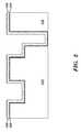
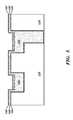
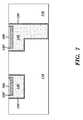
- the present inventionprovides a metal interconnect structure, which includes metal alloy capping layers.
- the originally deposited alloy capping layer element within the interconnect featureswill diffuse into and segregate onto top surface of the metal interconnect.
- the metal alloy capping materialis deposited on a reflowed copper surface and is not physically in contact with sidewalls of the interconnect features.
- electrical resistivity impactfrom residual alloy elements in the interconnect structure. That is, there is a reduction, of alloy elements inside the features of the metal interconnect structure.
- a second reflow annealing of the deposited metal alloy capping material on the pure copperenables sufficient amount of the metal alloy into the patterned features.
Landscapes
- Engineering & Computer Science (AREA)
- Physics & Mathematics (AREA)
- Condensed Matter Physics & Semiconductors (AREA)
- General Physics & Mathematics (AREA)
- Manufacturing & Machinery (AREA)
- Computer Hardware Design (AREA)
- Microelectronics & Electronic Packaging (AREA)
- Power Engineering (AREA)
- Internal Circuitry In Semiconductor Integrated Circuit Devices (AREA)
Abstract
Description
Claims (9)
Priority Applications (2)
| Application Number | Priority Date | Filing Date | Title |
|---|---|---|---|
| US13/653,665US8492274B2 (en) | 2011-11-07 | 2012-10-17 | Metal alloy cap integration |
| US13/892,265US8716127B2 (en) | 2011-11-07 | 2013-05-11 | Metal alloy cap integration |
Applications Claiming Priority (2)
| Application Number | Priority Date | Filing Date | Title |
|---|---|---|---|
| US13/290,557US20130112462A1 (en) | 2011-11-07 | 2011-11-07 | Metal Alloy Cap Integration |
| US13/653,665US8492274B2 (en) | 2011-11-07 | 2012-10-17 | Metal alloy cap integration |
Related Parent Applications (1)
| Application Number | Title | Priority Date | Filing Date |
|---|---|---|---|
| US13/290,557Continuation-In-PartUS20130112462A1 (en) | 2011-11-07 | 2011-11-07 | Metal Alloy Cap Integration |
Related Child Applications (1)
| Application Number | Title | Priority Date | Filing Date |
|---|---|---|---|
| US13/892,265ContinuationUS8716127B2 (en) | 2011-11-07 | 2013-05-11 | Metal alloy cap integration |
Publications (2)
| Publication Number | Publication Date |
|---|---|
| US20130115767A1 US20130115767A1 (en) | 2013-05-09 |
| US8492274B2true US8492274B2 (en) | 2013-07-23 |
Family
ID=48223964
Family Applications (2)
| Application Number | Title | Priority Date | Filing Date |
|---|---|---|---|
| US13/653,665ActiveUS8492274B2 (en) | 2011-11-07 | 2012-10-17 | Metal alloy cap integration |
| US13/892,265ActiveUS8716127B2 (en) | 2011-11-07 | 2013-05-11 | Metal alloy cap integration |
Family Applications After (1)
| Application Number | Title | Priority Date | Filing Date |
|---|---|---|---|
| US13/892,265ActiveUS8716127B2 (en) | 2011-11-07 | 2013-05-11 | Metal alloy cap integration |
Country Status (1)
| Country | Link |
|---|---|
| US (2) | US8492274B2 (en) |
Cited By (5)
| Publication number | Priority date | Publication date | Assignee | Title |
|---|---|---|---|---|
| US20140030886A1 (en)* | 2011-03-30 | 2014-01-30 | Tokyo Electron Limited | Method for forming copper wiring |
| US8716127B2 (en)* | 2011-11-07 | 2014-05-06 | International Business Machines Corporation | Metal alloy cap integration |
| US9349691B2 (en) | 2014-07-24 | 2016-05-24 | International Business Machines Corporation | Semiconductor device with reduced via resistance |
| US9455182B2 (en) | 2014-08-22 | 2016-09-27 | International Business Machines Corporation | Interconnect structure with capping layer and barrier layer |
| US10672649B2 (en) | 2017-11-08 | 2020-06-02 | International Business Machines Corporation | Advanced BEOL interconnect architecture |
Families Citing this family (9)
| Publication number | Priority date | Publication date | Assignee | Title |
|---|---|---|---|---|
| US8969197B2 (en)* | 2012-05-18 | 2015-03-03 | International Business Machines Corporation | Copper interconnect structure and its formation |
| KR102085086B1 (en)* | 2013-10-29 | 2020-03-05 | 삼성전자주식회사 | Semiconductor device and method of forming the same |
| US9305836B1 (en) | 2014-11-10 | 2016-04-05 | International Business Machines Corporation | Air gap semiconductor structure with selective cap bilayer |
| US9711452B2 (en) | 2014-12-05 | 2017-07-18 | International Business Machines Corporation | Optimized wires for resistance or electromigration |
| CN107170705A (en)* | 2016-03-08 | 2017-09-15 | 中芯国际集成电路制造(上海)有限公司 | Formation method of interconnect structure |
| US9824970B1 (en)* | 2016-06-27 | 2017-11-21 | Globalfoundries Inc. | Methods that use at least a dual damascene process and, optionally, a single damascene process to form interconnects with hybrid metallization and the resulting structures |
| US11004735B2 (en) | 2018-09-14 | 2021-05-11 | International Business Machines Corporation | Conductive interconnect having a semi-liner and no top surface recess |
| US10811353B2 (en)* | 2018-10-22 | 2020-10-20 | International Business Machines Corporation | Sub-ground rule e-Fuse structure |
| US11328954B2 (en) | 2020-03-13 | 2022-05-10 | International Business Machines Corporation | Bi metal subtractive etch for trench and via formation |
Citations (15)
| Publication number | Priority date | Publication date | Assignee | Title |
|---|---|---|---|---|
| US5585673A (en) | 1992-02-26 | 1996-12-17 | International Business Machines Corporation | Refractory metal capped low resistivity metal conductor lines and vias |
| US5695810A (en) | 1996-11-20 | 1997-12-09 | Cornell Research Foundation, Inc. | Use of cobalt tungsten phosphide as a barrier material for copper metallization |
| KR20010061524A (en) | 1999-12-28 | 2001-07-07 | 박종섭 | Method of forming a metal line in a semiconductor device |
| US6342733B1 (en) | 1999-07-27 | 2002-01-29 | International Business Machines Corporation | Reduced electromigration and stressed induced migration of Cu wires by surface coating |
| US6387805B2 (en) | 1997-05-08 | 2002-05-14 | Applied Materials, Inc. | Copper alloy seed layer for copper metallization |
| US6599828B1 (en) | 1993-12-28 | 2003-07-29 | Intel Corporation | Copper reflow process |
| US6706625B1 (en) | 2002-12-06 | 2004-03-16 | Chartered Semiconductor Manufacturing Ltd. | Copper recess formation using chemical process for fabricating barrier cap for lines and vias |
| US20040113279A1 (en) | 2002-12-16 | 2004-06-17 | International Business Machines Corporation | Copper recess process with application to selective capping and electroless plating |
| US6903014B2 (en) | 1996-04-12 | 2005-06-07 | Micron Technology, Inc. | Low temperature reflow method for filling high aspect ratio contacts |
| US20060276030A1 (en)* | 2005-06-01 | 2006-12-07 | Jean Wang | Novel method to implement stress free polishing |
| US20080277791A1 (en)* | 2004-12-23 | 2008-11-13 | Jae-Suk Lee | Semiconductor Devices and Methods for Manufacturing the Same |
| US20090098728A1 (en) | 2007-10-11 | 2009-04-16 | Stephan Grunow | Structure cu liner for interconnects using a double-bilayer processing scheme |
| US7538027B2 (en) | 2006-03-20 | 2009-05-26 | Kobe Steel, Ltd. | Fabrication method for semiconductor interconnections |
| US20090160055A1 (en) | 2007-12-19 | 2009-06-25 | Lavoie Adrien R | IC solder reflow method and materials |
| US20090169760A1 (en) | 2007-12-31 | 2009-07-02 | Rohan Akolkar | Copper metallization utilizing reflow on noble metal liners |
Family Cites Families (5)
| Publication number | Priority date | Publication date | Assignee | Title |
|---|---|---|---|---|
| US6605874B2 (en) | 2001-12-19 | 2003-08-12 | Intel Corporation | Method of making semiconductor device using an interconnect |
| US6955984B2 (en) | 2003-05-16 | 2005-10-18 | Taiwan Semiconductor Manufacturing Company, Ltd. | Surface treatment of metal interconnect lines |
| US7714441B2 (en) | 2004-08-09 | 2010-05-11 | Lam Research | Barrier layer configurations and methods for processing microelectronic topographies having barrier layers |
| JP2006093357A (en) | 2004-09-22 | 2006-04-06 | Ebara Corp | Semiconductor device and manufacturing method thereof, and processing solution |
| US8492274B2 (en)* | 2011-11-07 | 2013-07-23 | International Business Machines Corporation | Metal alloy cap integration |
- 2012
- 2012-10-17USUS13/653,665patent/US8492274B2/enactiveActive
- 2013
- 2013-05-11USUS13/892,265patent/US8716127B2/enactiveActive
Patent Citations (16)
| Publication number | Priority date | Publication date | Assignee | Title |
|---|---|---|---|---|
| US6323554B1 (en) | 1992-02-26 | 2001-11-27 | International Business Machines Corporation | Refractory metal capped low resistivity metal conductor lines and vias formed using PVD and CVD |
| US5585673A (en) | 1992-02-26 | 1996-12-17 | International Business Machines Corporation | Refractory metal capped low resistivity metal conductor lines and vias |
| US6599828B1 (en) | 1993-12-28 | 2003-07-29 | Intel Corporation | Copper reflow process |
| US6903014B2 (en) | 1996-04-12 | 2005-06-07 | Micron Technology, Inc. | Low temperature reflow method for filling high aspect ratio contacts |
| US5695810A (en) | 1996-11-20 | 1997-12-09 | Cornell Research Foundation, Inc. | Use of cobalt tungsten phosphide as a barrier material for copper metallization |
| US6387805B2 (en) | 1997-05-08 | 2002-05-14 | Applied Materials, Inc. | Copper alloy seed layer for copper metallization |
| US6342733B1 (en) | 1999-07-27 | 2002-01-29 | International Business Machines Corporation | Reduced electromigration and stressed induced migration of Cu wires by surface coating |
| KR20010061524A (en) | 1999-12-28 | 2001-07-07 | 박종섭 | Method of forming a metal line in a semiconductor device |
| US6706625B1 (en) | 2002-12-06 | 2004-03-16 | Chartered Semiconductor Manufacturing Ltd. | Copper recess formation using chemical process for fabricating barrier cap for lines and vias |
| US20040113279A1 (en) | 2002-12-16 | 2004-06-17 | International Business Machines Corporation | Copper recess process with application to selective capping and electroless plating |
| US20080277791A1 (en)* | 2004-12-23 | 2008-11-13 | Jae-Suk Lee | Semiconductor Devices and Methods for Manufacturing the Same |
| US20060276030A1 (en)* | 2005-06-01 | 2006-12-07 | Jean Wang | Novel method to implement stress free polishing |
| US7538027B2 (en) | 2006-03-20 | 2009-05-26 | Kobe Steel, Ltd. | Fabrication method for semiconductor interconnections |
| US20090098728A1 (en) | 2007-10-11 | 2009-04-16 | Stephan Grunow | Structure cu liner for interconnects using a double-bilayer processing scheme |
| US20090160055A1 (en) | 2007-12-19 | 2009-06-25 | Lavoie Adrien R | IC solder reflow method and materials |
| US20090169760A1 (en) | 2007-12-31 | 2009-07-02 | Rohan Akolkar | Copper metallization utilizing reflow on noble metal liners |
Cited By (19)
| Publication number | Priority date | Publication date | Assignee | Title |
|---|---|---|---|---|
| US20140030886A1 (en)* | 2011-03-30 | 2014-01-30 | Tokyo Electron Limited | Method for forming copper wiring |
| US8716127B2 (en)* | 2011-11-07 | 2014-05-06 | International Business Machines Corporation | Metal alloy cap integration |
| US10553483B2 (en) | 2014-07-24 | 2020-02-04 | International Business Machines Corporation | Semiconductor device with reduced via resistance |
| US9349691B2 (en) | 2014-07-24 | 2016-05-24 | International Business Machines Corporation | Semiconductor device with reduced via resistance |
| US11488862B2 (en) | 2014-07-24 | 2022-11-01 | Tessera Llc | Semiconductor device with reduced via resistance |
| US9859160B2 (en) | 2014-07-24 | 2018-01-02 | International Business Machines Corporation | Semiconductor device with reduced via resistance |
| US11222815B2 (en) | 2014-07-24 | 2022-01-11 | Tessera, Inc. | Semiconductor device with reduced via resistance |
| US10804147B2 (en) | 2014-07-24 | 2020-10-13 | Tessera, Inc. | Semiconductor device with reduced via resistance |
| US9953869B2 (en) | 2014-07-24 | 2018-04-24 | International Business Machines Corporation | Semiconductor device with reduced via resistance |
| US9601371B2 (en) | 2014-08-22 | 2017-03-21 | International Business Machines Corporation | Interconnect structure with barrier layer |
| US10325806B2 (en) | 2014-08-22 | 2019-06-18 | International Business Machines Corporation | Copper interconnect structure with manganese oxide barrier layer |
| US10593591B2 (en) | 2014-08-22 | 2020-03-17 | Tessera, Inc. | Interconnect structure |
| US10770347B2 (en) | 2014-08-22 | 2020-09-08 | Tessera, Inc. | Interconnect structure |
| US9947579B2 (en) | 2014-08-22 | 2018-04-17 | International Business Machines Corporation | Copper interconnect structure with manganese oxide barrier layer |
| US9947581B2 (en) | 2014-08-22 | 2018-04-17 | International Business Machines Corporation | Method of forming a copper based interconnect structure |
| US11232983B2 (en) | 2014-08-22 | 2022-01-25 | Tessera, Inc. | Copper interconnect structure with manganese barrier layer |
| US9455182B2 (en) | 2014-08-22 | 2016-09-27 | International Business Machines Corporation | Interconnect structure with capping layer and barrier layer |
| US11804405B2 (en) | 2014-08-22 | 2023-10-31 | Tessera Llc | Method of forming copper interconnect structure with manganese barrier layer |
| US10672649B2 (en) | 2017-11-08 | 2020-06-02 | International Business Machines Corporation | Advanced BEOL interconnect architecture |
Also Published As
| Publication number | Publication date |
|---|---|
| US8716127B2 (en) | 2014-05-06 |
| US20130115767A1 (en) | 2013-05-09 |
| US20130252419A1 (en) | 2013-09-26 |
Similar Documents
| Publication | Publication Date | Title |
|---|---|---|
| US8492274B2 (en) | Metal alloy cap integration | |
| US8796853B2 (en) | Metallic capped interconnect structure with high electromigration resistance and low resistivity | |
| US7605072B2 (en) | Interconnect structure with a barrier-redundancy feature | |
| US8525339B2 (en) | Hybrid copper interconnect structure and method of fabricating same | |
| US7834457B2 (en) | Bilayer metal capping layer for interconnect applications | |
| US8354751B2 (en) | Interconnect structure for electromigration enhancement | |
| US8288276B2 (en) | Method of forming an interconnect structure including a metallic interfacial layer located at a bottom via portion | |
| US7666787B2 (en) | Grain growth promotion layer for semiconductor interconnect structures | |
| US8669182B2 (en) | Metal cap with ultra-low κ dielectric material for circuit interconnect applications | |
| US9875966B1 (en) | Method and structure of forming low resistance interconnects | |
| US8889546B2 (en) | Discontinuous/non-uniform metal cap structure and process for interconnect integration | |
| US8802563B2 (en) | Surface repair structure and process for interconnect applications | |
| US10170419B2 (en) | Biconvex low resistance metal wire | |
| US20130112462A1 (en) | Metal Alloy Cap Integration | |
| US20090072406A1 (en) | Interconnect structure with improved electromigration resistance and method of fabricating same | |
| US9859219B1 (en) | Copper wiring structures with copper titanium encapsulation | |
| US9773735B1 (en) | Geometry control in advanced interconnect structures | |
| US20240332165A1 (en) | Offset via formation for flexible routing |
Legal Events
| Date | Code | Title | Description |
|---|---|---|---|
| AS | Assignment | Owner name:INTERNATIONAL BUSINESS MACHINES CORPORATION, NEW Y Free format text:ASSIGNMENT OF ASSIGNORS INTEREST;ASSIGNORS:YANG, CHIH-CHAO;BERGENDAHL, MARC A;HOLMES, STEVEN J.;AND OTHERS;SIGNING DATES FROM 20121009 TO 20121012;REEL/FRAME:029172/0403 | |
| STCF | Information on status: patent grant | Free format text:PATENTED CASE | |
| AS | Assignment | Owner name:GLOBALFOUNDRIES U.S. 2 LLC, NEW YORK Free format text:ASSIGNMENT OF ASSIGNORS INTEREST;ASSIGNOR:INTERNATIONAL BUSINESS MACHINES CORPORATION;REEL/FRAME:036550/0001 Effective date:20150629 | |
| AS | Assignment | Owner name:GLOBALFOUNDRIES INC., CAYMAN ISLANDS Free format text:ASSIGNMENT OF ASSIGNORS INTEREST;ASSIGNORS:GLOBALFOUNDRIES U.S. 2 LLC;GLOBALFOUNDRIES U.S. INC.;REEL/FRAME:036779/0001 Effective date:20150910 | |
| FPAY | Fee payment | Year of fee payment:4 | |
| AS | Assignment | Owner name:WILMINGTON TRUST, NATIONAL ASSOCIATION, DELAWARE Free format text:SECURITY AGREEMENT;ASSIGNOR:GLOBALFOUNDRIES INC.;REEL/FRAME:049490/0001 Effective date:20181127 | |
| AS | Assignment | Owner name:GLOBALFOUNDRIES U.S. INC., CALIFORNIA Free format text:ASSIGNMENT OF ASSIGNORS INTEREST;ASSIGNOR:GLOBALFOUNDRIES INC.;REEL/FRAME:054633/0001 Effective date:20201022 | |
| AS | Assignment | Owner name:GLOBALFOUNDRIES INC., CAYMAN ISLANDS Free format text:RELEASE BY SECURED PARTY;ASSIGNOR:WILMINGTON TRUST, NATIONAL ASSOCIATION;REEL/FRAME:054636/0001 Effective date:20201117 | |
| MAFP | Maintenance fee payment | Free format text:PAYMENT OF MAINTENANCE FEE, 8TH YEAR, LARGE ENTITY (ORIGINAL EVENT CODE: M1552); ENTITY STATUS OF PATENT OWNER: LARGE ENTITY Year of fee payment:8 | |
| AS | Assignment | Owner name:GLOBALFOUNDRIES U.S. INC., NEW YORK Free format text:RELEASE BY SECURED PARTY;ASSIGNOR:WILMINGTON TRUST, NATIONAL ASSOCIATION;REEL/FRAME:056987/0001 Effective date:20201117 | |
| MAFP | Maintenance fee payment | Free format text:PAYMENT OF MAINTENANCE FEE, 12TH YEAR, LARGE ENTITY (ORIGINAL EVENT CODE: M1553); ENTITY STATUS OF PATENT OWNER: LARGE ENTITY Year of fee payment:12 |