US8491636B2 - Method and apparatus for inflating and deflating balloon catheters - Google Patents
Method and apparatus for inflating and deflating balloon cathetersDownload PDFInfo
- Publication number
- US8491636B2 US8491636B2US11/581,592US58159206AUS8491636B2US 8491636 B2US8491636 B2US 8491636B2US 58159206 AUS58159206 AUS 58159206AUS 8491636 B2US8491636 B2US 8491636B2
- Authority
- US
- United States
- Prior art keywords
- fluid
- balloon
- coolant
- catheter
- lumen
- Prior art date
- Legal status (The legal status is an assumption and is not a legal conclusion. Google has not performed a legal analysis and makes no representation as to the accuracy of the status listed.)
- Expired - Fee Related, expires
Links
Images


Classifications
- A—HUMAN NECESSITIES
- A61—MEDICAL OR VETERINARY SCIENCE; HYGIENE
- A61B—DIAGNOSIS; SURGERY; IDENTIFICATION
- A61B18/00—Surgical instruments, devices or methods for transferring non-mechanical forms of energy to or from the body
- A61B18/02—Surgical instruments, devices or methods for transferring non-mechanical forms of energy to or from the body by cooling, e.g. cryogenic techniques
- A—HUMAN NECESSITIES
- A61—MEDICAL OR VETERINARY SCIENCE; HYGIENE
- A61B—DIAGNOSIS; SURGERY; IDENTIFICATION
- A61B18/00—Surgical instruments, devices or methods for transferring non-mechanical forms of energy to or from the body
- A61B18/04—Surgical instruments, devices or methods for transferring non-mechanical forms of energy to or from the body by heating
- A61B18/12—Surgical instruments, devices or methods for transferring non-mechanical forms of energy to or from the body by heating by passing a current through the tissue to be heated, e.g. high-frequency current
- A61B18/14—Probes or electrodes therefor
- A61B18/1492—Probes or electrodes therefor having a flexible, catheter-like structure, e.g. for heart ablation
- A—HUMAN NECESSITIES
- A61—MEDICAL OR VETERINARY SCIENCE; HYGIENE
- A61M—DEVICES FOR INTRODUCING MEDIA INTO, OR ONTO, THE BODY; DEVICES FOR TRANSDUCING BODY MEDIA OR FOR TAKING MEDIA FROM THE BODY; DEVICES FOR PRODUCING OR ENDING SLEEP OR STUPOR
- A61M25/00—Catheters; Hollow probes
- A61M25/10—Balloon catheters
- A61M25/1011—Multiple balloon catheters
- A—HUMAN NECESSITIES
- A61—MEDICAL OR VETERINARY SCIENCE; HYGIENE
- A61B—DIAGNOSIS; SURGERY; IDENTIFICATION
- A61B17/00—Surgical instruments, devices or methods
- A61B17/22—Implements for squeezing-off ulcers or the like on inner organs of the body; Implements for scraping-out cavities of body organs, e.g. bones; for invasive removal or destruction of calculus using mechanical vibrations; for removing obstructions in blood vessels, not otherwise provided for
- A61B2017/22051—Implements for squeezing-off ulcers or the like on inner organs of the body; Implements for scraping-out cavities of body organs, e.g. bones; for invasive removal or destruction of calculus using mechanical vibrations; for removing obstructions in blood vessels, not otherwise provided for with an inflatable part, e.g. balloon, for positioning, blocking, or immobilisation
- A—HUMAN NECESSITIES
- A61—MEDICAL OR VETERINARY SCIENCE; HYGIENE
- A61B—DIAGNOSIS; SURGERY; IDENTIFICATION
- A61B18/00—Surgical instruments, devices or methods for transferring non-mechanical forms of energy to or from the body
- A61B2018/00053—Mechanical features of the instrument of device
- A61B2018/00214—Expandable means emitting energy, e.g. by elements carried thereon
- A61B2018/0022—Balloons
- A—HUMAN NECESSITIES
- A61—MEDICAL OR VETERINARY SCIENCE; HYGIENE
- A61B—DIAGNOSIS; SURGERY; IDENTIFICATION
- A61B18/00—Surgical instruments, devices or methods for transferring non-mechanical forms of energy to or from the body
- A61B18/02—Surgical instruments, devices or methods for transferring non-mechanical forms of energy to or from the body by cooling, e.g. cryogenic techniques
- A61B2018/0212—Surgical instruments, devices or methods for transferring non-mechanical forms of energy to or from the body by cooling, e.g. cryogenic techniques using an instrument inserted into a body lumen, e.g. catheter
- A—HUMAN NECESSITIES
- A61—MEDICAL OR VETERINARY SCIENCE; HYGIENE
- A61B—DIAGNOSIS; SURGERY; IDENTIFICATION
- A61B18/00—Surgical instruments, devices or methods for transferring non-mechanical forms of energy to or from the body
- A61B18/02—Surgical instruments, devices or methods for transferring non-mechanical forms of energy to or from the body by cooling, e.g. cryogenic techniques
- A61B2018/0231—Characteristics of handpieces or probes
- A61B2018/0262—Characteristics of handpieces or probes using a circulating cryogenic fluid
- A—HUMAN NECESSITIES
- A61—MEDICAL OR VETERINARY SCIENCE; HYGIENE
- A61M—DEVICES FOR INTRODUCING MEDIA INTO, OR ONTO, THE BODY; DEVICES FOR TRANSDUCING BODY MEDIA OR FOR TAKING MEDIA FROM THE BODY; DEVICES FOR PRODUCING OR ENDING SLEEP OR STUPOR
- A61M25/00—Catheters; Hollow probes
- A61M25/10—Balloon catheters
- A61M25/1018—Balloon inflating or inflation-control devices
- A61M25/10184—Means for controlling or monitoring inflation or deflation
Definitions
- the present inventionrelates to a method and system for inflating and deflating balloon catheters and more specifically to a method and system for controlling the inflation and deflation of balloon catheters in order to safely and effectively ablate a tissue region.
- catheter based deviceswhich employ the flow of cryogenic working fluids therein, to selectively freeze, or “cold-treat”, targeted tissues within the body.
- catheter based devicesare desirable for various medical and surgical applications in that they are relatively non-invasive and allow for precise treatment of localized discrete tissues that are otherwise inaccessible. Catheters may be easily inserted and navigated through the blood vessels and arteries, allowing non-invasive access to areas of the body with relatively little trauma.
- a cryogenic deviceuses the energy transfer derived from thermodynamic changes occurring in the flow of a cryogen therethrough to create a net transfer of heat flow from the target tissue to the device, typically achieved by cooling a portion of the device to very low temperature through conductive and convective heat transfer between the cryogen and target tissue.
- the quality and magnitude of heat transferis regulated by the device configuration and control of the cryogen flow regime within the device.
- a cryogenic deviceuses the energy transfer derived from thermodynamic changes occurring in the flow of a refrigerant through the device. This energy transfer is then utilized to create a net transfer of heat flow from the target tissue to the device, typically achieved by cooling a portion of the device to very low temperature through conductive and convective heat transfer between the refrigerant and target tissue. The quality and magnitude of heat transfer is regulated by device configuration and control of the refrigerant flow regime within the device.
- coolingcan be achieved through injection of high pressure refrigerant through an orifice.
- the refrigerantundergoes two primary thermodynamic changes: (i) expanding to low pressure and temperature through positive Joule-Thomson throttling, and (ii) undergoing a phase change from liquid to vapor, thereby absorbing heat of vaporization.
- the resultant flow of low temperature refrigerant through the deviceacts to absorb heat from the target tissue and thereby cool the tissue to the desired temperature.
- refrigerantOnce refrigerant is injected through an orifice, it may be expanded inside of a closed expansion chamber, which is positioned proximal to the target tissue.
- Devices with an expandable membrane, such as a balloonare employed as expansion chambers.
- refrigerantis supplied through a catheter tube into an expandable balloon coupled to such catheter, wherein the refrigerant acts to both: (i) expand the balloon near the target tissue for the purpose of positioning the balloon, and (ii) cool the target tissue proximal to the balloon to cold-treat adjacent tissue.
- cryomappingis a procedure that chills conducting target tissue to create a transient electrical effect. By temporarily chilling the target tissue, it allows for precise site confirmation in order to prevent inadvertent ablation. During cryomapping, a procedure known as cryoadhesion takes place.
- Cryoadhesionis a procedure that ensures the catheter tip remains at the target cite for a seamless transition to cryoablation.
- the tip of the catheterfirmly attaches to the tissue when it freezes thereby reducing the risk of accidental slippage of the catheter tip. Therefore, during unmonitored balloon deflation, i.e. if the balloon deflates too quickly, the balloon, adhering to the tissue walls, may cause severe damage.
- the present inventionadvantageously provides a method and system for controllably inflating and deflating a balloon catheter.
- the method and systemallows for the monitoring of the inflation and deflation phases of a catheter system in order to allow ablation to take place, while detecting unwanted leaks of refrigerant into the bloodstream. Balloon leaks are identified, safety evacuation routes are provided, and a controlled deflation mechanism is presented that prevents damage to the interior blood vessel and tissue region, which may occur during unmonitored deflation due to the adherence of the expandable membrane to the interior of the vessel.
- a method of inflating and deflating a catheter during an ablation processcomprising the steps of controllably inflating the expandable membrane to a target pressure or volume, ablating a desired tissue region while maintaining the target pressure or volume of the expandable membrane, and controllably deflating the expandable membrane so as not to damage desired tissue region.
- a method for inflating and deflating a catheter having an expandable membrane during an ablation processis provided.
- the catheteris part of a catheter system including a console, the catheter, and an umbilical system coupling the console to the catheter.
- the methodcomprises the steps of evacuating air from the expandable membrane by creating a vacuum in the expandable membrane, controllably inflating the expandable membrane proximate a desired tissue region, wherein the expandable membrane is inflated to a target pressure or volume in order to provide sufficient mechanical force against the desired tissue region, ablating the desired tissue region while maintaining the expandable membrane at the target pressure or volume, and controllably deflating the expandable membrane such that the desired tissue region is not damaged.
- an apparatus for inflating and deflating a catheter having an expandable membranecomprises a console, the console including means for controlling the inflation and deflation of the expandable membrane and for determining if the expandable membrane maintains a target pressure or volume.
- the consolealso includes a pressurized inflation source.
- the apparatusfurther includes a catheter, and an umbilical system coupling the console to the expandable membrane and delivering pressurized media to the expandable membrane.
- FIG. 1Aillustrates a first embodiment of a double balloon catheter used in conjunction with the present invention
- FIG. 1Billustrates a catheter system used in conjunction with the present invention
- FIG. 1Cillustrates the double balloon catheter of FIG. 1A including a flow sensor located in the handle of the catheter;
- FIG. 1Dillustrates the double balloon catheter of FIG. 1A including a pressure sensor located in the handle of the catheter;
- FIGS. 2A-2Eillustrate a cryoablation system incorporating various embodiments of the apparatus and method of the present invention
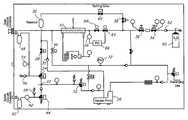
- FIG. 3is a schematic representing the mechanical components of the control console of the present invention.
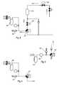
- FIG. 4is a schematic representing the mechanical components of the inflation circuit portion of the control console of the present invention.
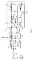
- FIG. 5is a schematic representing the mechanical components of the deflation circuit and main vacuum path of the control console of the present invention.
- FIG. 6is a schematic representing the mechanical components of the safety vacuum path of the control console of the present invention.
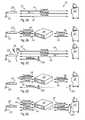
- FIG. 7is a schematic representation of the embodiment illustrated in FIG. 2A ;
- FIG. 8is a schematic representation of the embodiment illustrated in FIG. 2B ;
- FIG. 9is a schematic representation of the embodiment illustrated in FIG. 2C ;
- FIG. 10is a schematic representation of the embodiment illustrated in FIG. 2D ;
- FIG. 11is a schematic representation of the embodiment illustrated in FIG. 2E ;
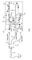
- FIG. 12is a schematic representation of an embodiment of a control console of the present invention.
- FIG. 13is a flow chart of an exemplary use of a control console in accordance with the present invention.
- the present inventionis an apparatus and method for controlling the inflation and deflation of balloon catheters.
- the inventionrequires four steps to properly control the inflation and deflation of the balloon catheter.
- An intermediary control stationcontaining a shut off valve and/or a coolant source may be implemented to assist in properly monitoring, controlling and maintaining the target balloon pressure and/or volume.
- the catheter 1includes a handle 2 having a number of proximal connector ports 3 a - 3 d .
- Port 3 amay be a first vacuum connector, having a first vacuum lumen therein, such as a 10 French lumen.
- Port 3 bmay be a coaxial connector having both a vacuum lumen and injection therein, the vacuum lumen being a second vacuum lumen, such as a 8 French lumen.
- Port 3 cmay be an electrical connector.
- Port 3 dmay be a guidewire luer hub.
- the handle 2further includes a blood detection board 4 and pressure relief valve 5 .
- the distal end portion of the catheter 1includes two balloons: an inner balloon 6 a and an outer balloon 6 b surrounding inner balloon 6 a .
- a soft distal tip 7is located just distal to the two balloons 6 a and 6 b .
- vacuum applied through the ports 3 a and 3 bwill serve to draw any fluid within balloons 6 a and 6 b along arrows V out of the balloons and the catheter.
- Radiopaque marker bands Mare located proximate the exit point of the refrigerant injected into balloon 6 a to aid in the positioning and tracking of the device.
- Catheter 1includes an elongate shaft having a guidewire 8 and an inner shaft 9 a and outer shaft 9 b .
- Exemplary embodiments of the inner shaft 9 ainclude an 8 French shaft, while exemplary embodiments of the outer shaft 9 b include a 10 French shaft.
- FIG. 1BA typical catheter system 10 is shown in FIG. 1B .
- the systemincludes a console 20 coupled to one end of an umbilical system 12 .
- the opposing end of umbilical system 12is coupled to an energy treatment device 22 .
- Energy treatment device 22may be a medical probe, a catheter, a balloon-catheter, as well as other devices commonly known in the art that are smooth enough to pass easily through blood vessels and heart valves.
- the energy treatment device 22includes a balloon structure 23 that can be a single wall or a double wall configuration, wherein the double wall configuration places the space between balloon walls in communication with a vacuum source.
- Umbilical system 12is comprised of three separate umbilicals: a coaxial cable umbilical 14 , an electrical umbilical 16 and a vacuum umbilical 18 .
- An outer vacuum umbilicalis used in the case of a double balloon system; it is not necessary for a single balloon system having only one vacuum lumen. If the user wishes to perform an RF ablation procedure, radiofrequency energy can be provided to electrodes on device 22 via electrical umbilical 16 to perform an RF ablation technique as is common in the art.
- Electrical umbilical 16can include an ECG box 82 to facilitate a connection from electrodes on catheter 22 (not shown) to an ECG monitor.
- Coaxial umbilical 14includes both a cooling injection umbilical and a vacuum umbilical that provide respective inlet and return paths for a refrigerant or coolant used to cool a tissue-treating end of device 22 .
- the vacuum umbilical 18is used as safety conduit to allow excess coolant or gas to escape from device 22 if the pressure within the balloon on device 22 exceeds a predefined limit.
- the vacuum umbilical 18can also be used to capture air through a leak of the outer vacuum system where it is outside the patient and as a lumen to ingress blood when in the patient.
- catheter system 10may include one or more sensors #, which are used to monitor the amount of fluid or gas refrigerant injected through the umbilical system and into the balloons. It is contemplated that the sensors may be located in one of several locations throughout catheter system 10 . For example, sensor 11 may be located in console 20 , ECG Box 82 , and/or handle 2 .
- a flow sensor 13 shown in FIG. 1Cmeasures the rate or speed of fluid or gas at a certain location.
- An exemplary embodiment of flow sensor 13is the Microbridge Mass Air Flow Sensor by Honeywell®.
- one or more sensors 11may be a pressure sensor 15 as shown in FIG. 1D .
- Pressure sensor 15 in FIG. 1Dis a differential pressure sensor that can determine the amount of pressure in the balloons by determining the difference in pressure between points p 1 and p 2 and the velocity through the restriction point d.
- An exemplary embodiment of pressure sensor 15is the 26PC SMT Pressure Sensor by Honeywell®.
- FIGS. 2A-2Eillustrate different embodiments of the catheter system 10 of the present invention.
- the inflation/deflation system described hereincan be used with both single and double balloon systems.
- the refrigerantis sprayed into the balloon and creates a circumferential region of cooling around the balloon's perimeter.
- the refrigerantexpands and the vapor is drawn back into the console via the return vacuum lumen.
- a second balloon and second vacuum lumenenvelop the single balloon system and are always maintained under vacuum for safety reasons.
- the vacuum of the outer balloonwill capture refrigerant escaping through any breach of the inner balloon system.
- a flow switch mounted on the outer vacuum systemis used to monitor any flow activity. Under normal operation, no fluid should pass through the outer vacuum system. Any discussion of a “flow switch” herein implies a double balloon system. Otherwise, all inflation/deflation methods also apply to a single balloon catheter.
- Each embodimentincludes a console 20 or console 21 , an umbilical system comprised of varying combinations of separate umbilicals, and an ablation device 22 .
- FIGS. 2A-2EEach of the embodiments shown in FIGS. 2A-2E is represented by more detailed corresponding schematics in FIGS. 7-11 , respectively, and are discussed in greater detail below.
- FIG. 2Arepresents a typical catheter ablation system 10 .
- Console 20is coupled to a catheter 22 via an umbilical system 12 , comprised of coaxial umbilical 14 , which transfers coolant from console 20 to catheter 22 and provides a return conduit for the coolant, electrical umbilical 16 , which transfers RF energy from console 20 to catheter 22 during an RF ablation procedure or electrical signals during a cryoablation procedure, and safety vacuum umbilical 18 , to allow for quick evacuation of coolant if needed.
- umbilical system 12comprised of coaxial umbilical 14 , which transfers coolant from console 20 to catheter 22 and provides a return conduit for the coolant, electrical umbilical 16 , which transfers RF energy from console 20 to catheter 22 during an RF ablation procedure or electrical signals during a cryoablation procedure, and safety vacuum umbilical 18 , to allow for quick evacuation of coolant if needed.
- Coolantis provided by a coolant source within console 20 .
- Coolanttypically N 2 O
- Coolantpasses through the internal piping of console 20 before being transferred to catheter 22 via the coaxial umbilical 14 .
- the coolantis released inside the catheter tip cavity, which is under vacuum. Both the phase change from liquid to gas and the sudden expansion of the coolant are endothermic reactions, causing a temperature differential which results in the catheter tip or balloon freezing.
- the coolant vaporis then returned through the vacuum path via umbilical 14 and into console 20 , where it is evacuated through a scavenging line.
- FIG. 2Brepresents another catheter ablation system.
- an intermediary station 74is inserted into the catheter system.
- station 74contains detection valves to detect a drop in balloon pressure which might indicate a leak, and shut off valves to terminate balloon inflation if necessary.
- Station 74is coupled to console 21 and catheter 22 via electrical umbilical 16 and coaxial umbilical 14 .
- Vacuum umbilical 18provides an emergency evacuation path for coolant from the catheter.
- FIG. 2Crepresents the catheter ablation system of FIG. 2A including a secondary coolant source 78 used to re-inflate the expandable membrane, or balloon 23 of catheter 22 via syringe 76 .
- FIG. 2Dillustrates two possible configurations for the ablation system.
- a secondary coolant sourceincludes a small tank or canister 80 located within an intermediary station 74 .
- the secondary coolant sourceincludes a small tank or canister 60 located inside the console 21 .
- the secondary coolant sourceis independent from the source of cooling provided by other components within the console 21 (the primary coolant source), and it does not require the same type of refrigerant that is provided by the primary coolant source.
- FIG. 2Eillustrates a configuration where the secondary cooling source and the primary cooling source are unified and thus share the same source of refrigerant.
- FIG. 3refers to a schematic representing the console 20 portrayed in FIGS. 2A and 2C .
- the schematic shownis designed specially for balloon catheters and contains a series of two and three-way solenoid valves and regulators that assist in monitoring the pressure of the balloon catheter 23 , which may drop quickly if a leak of fluid occurs.
- Device 22shown in FIGS. 2A-2E ) is a catheter with an expandable membrane 23 at its distal end.
- Console 20is represented by the schematic in FIG. 3 that shows the layout of the internal mechanical components of console 20 .
- the systemis operated in four phases.
- the first phaseis the evacuation/flushing phase.
- the catheter 22When the catheter 22 is inserted inside the patient it is first necessary to evacuate air molecules from within the catheter, air contained inside the umbilical connecting the catheter 22 to the console 20 , as well as from the catheter shaft itself. Although it is not theoretically possible to evacuate 100% of the air molecules, by minimizing the amount of air within the umbilical and catheter shaft, the catheter is prepared for inflation and then ablation, while minimizing the dangers associated with fluid egress.
- a 3-way solenoid valve 24is open toward vacuum pump 26 , which ensures that there is a vacuum in catheter 22 .
- the 3-way solenoid valve 24can be replaced by a PID-driven proportional valve.
- the 2-way solenoid 28 that supports high pressureis closed to prevent any high-pressure gas from reservoir 30 from entering the inner vacuum system/balloon catheter during the refilling process.
- Reservoir 30could be a tube or reservoir containing enough fluid volume to fill the umbilical tubes and catheter 22 to a predefined pressure.
- a check valve 32will open to evacuate the exceeded amount of coolant such as, for example, nitrous oxide (N 2 O) in the system in order to keep a fixed amount of nitrous oxide in reservoir 30 .
- reservoir 30is filled with N 2 O received from N 2 O source 60 .
- the N 2 Ois received from a high pressure line after leaves tank 60 and passes through a series of regulators, namely, a first regulator 34 , a second regulator 36 and then into either a third regulator 38 or a proportional valve, that are adjusted to the predetermined pressure.
- the reservoir pressurecan be controlled through a pressure regulator 38 or through a proportional valve that would refill the tank with different pressure setpoints for different balloon sizes or different inflation pressures.
- the pressure setpointcan be programmed into a circuit, chip or other memory device that can be located in the handle.
- Refilling valve 40opens for a period of time and fills reservoir 30 .
- the 2-way solenoid valve 28remains closed. Also, during this phase, the system is under vacuum and provides verification for any leaks that occur.
- any breach of the inner or outer vacuum systemswill be detected by a high baseline flow through the console flow meter.
- a flow switch located in the console or in the catheter handle and mounted on the outer vacuum systemwill also detect a leak of air through a breach of the outer balloon or vacuum lumen.
- the flow switchis capable of detecting volumes of gas as little as 1 cc of vapor, and flow rates as little as 20 sccm.
- the balloon pressurecan also be controlled with a PID-driven proportional valve located on the return vacuum lumen or a three-way solenoid valve in series with a pressure switch or pressure transducer.
- balloon 23is inflated by injecting fluid or gas through the umbilical under a fixed flow pressure. This insures a defined and constant pressure inside the balloon in order to provide a mechanical force for inflation.
- An alternate way to inflate balloon 23is to use a fixed volume of inflation. This volume would be minimized in order to meet the constraints related to gas egress within the blood stream (maximum of 20 cc within 10 minutes) and meet the requirement for pressure needed to inflate the balloon under the harshest room conditions.
- FIG. 3illustrates the inflation portion of the console mechanics of FIG. 2 .
- valve 24is open toward reservoir 30 and valve 28 opens, while refilling valve 40 remains closed.
- a fixed amount of N 2 Ois injected to inflate balloon 23 in order to provide sufficient mechanical force for inflation. If a leak occurs in the balloon, the released volume of N 2 O would be no more than 20 cc.
- the solenoid valve 44(shown in FIG. 33 ) remains open during this phase in order to ensure a vacuum in the safety line.
- the flow switch 42( FIG. 3 ), detects leaks as small as 1 cc of vapor.
- Flow switch 42is active during all phases to prevent any leak of the inner balloon system in catheter 22 .
- the leak and blood detection systemsare still active and monitoring any blood ingress through the outer vacuum lumen. After air has been flushed from catheter 22 and the umbilicals connecting catheter 22 to console 20 , and balloon 23 has been inflated, ablation may now take place.
- a transition modefollows inflation but precedes ablation.
- a transition methodis needed to transition from closed pressurized volume to an open circuit, which allows the flow of refrigerant to enter and exit the catheter tip while at the same time controlling the balloon pressure in order to keep the balloon inflated and in place.
- a pressure switchwhich is adjusted to a pressure higher than atmospheric pressure but preferably lower than 20 psia, monitors the pressure inside the balloon catheter 22 .
- the solenoid valve 24remains closed until the pressure in the catheter is higher than the preset switch value after which the solenoid valve opens to allow evacuation of excess refrigerant.
- the solenoid valve 24closes to keep the balloon inflated and above atmospheric pressure.
- ablationis already initiated but the pressure switch controls the balloon pressure until refrigerant flow alone maintains the balloon open and above atmospheric pressure.
- the transition phaseis considered complete when certain conditions are met: 1) when the pressure switch commands the solenoid valve 24 to open to vacuum and the balloon pressure remains above the present switch value; 2) the duration of the transition phase exceeds a predetermined time; and 3) the injection pressure reaches a predetermined value that is adequate to generate enough flow to maintain the balloon open.
- Check valve 56is used to prevent any abnormal rise in the pressure in the catheter tip.
- Another check valve 58shown also in FIG. 6 , prevents any excessive pressure in the safety vacuum line and in the event the solenoid valve 44 is blocked.
- refrigerantis injected through the umbilical system into the ablation device 22 .
- N 2 O gasis released from source 60 and provides high pressure liquid through a check valve 62 and a series of pressure regulators 34 and 36 .
- Regulators 34 and 36are primary and secondary pressure regulators respectively, which serve to bring the gas pressure down to between 810 and approximately 840 psig.
- the liquid nitrous oxidegoes through a proportional valve 64 driven by a Proportional Integral Derivative (PID) controller 66 so that the refrigerant pressure can be varied from 0 psig to approximately 760 psig, and through an injection solenoid valve 68 which remains open.
- PIDProportional Integral Derivative
- the N 2 Othen passes through a sub-cooler 70 with various refrigeration components such as a compressor, a condenser, a capillary tube and a heat exchanger, which insures its liquid state through the umbilical and into the small diameter catheter injection tubing.
- a sub-cooler 70with various refrigeration components such as a compressor, a condenser, a capillary tube and a heat exchanger, which insures its liquid state through the umbilical and into the small diameter catheter injection tubing.
- solenoid vent valve 46is closed.
- the pressure switch 72will close when detecting a pressure higher than 15 psig, creating a failure signal.
- proportional valve 64is used to vary the pressure inside the injection line. This in turn will vary the flow rate of refrigerant to the catheter tip. An increase in the flow rate (less restriction by the regulator) lowers the temperature of the catheter tip. Conversely, decreasing the flow rate allows the catheter tip to be warmed by its surroundings.
- FIG. 5illustrates the deflation and main path circuitry of the present invention.
- the systemprovides a method to insure a controlled/slow deflation in order to prevent damaging the ablated tissue during balloon deflation. This can be a hazard due to cryoadhesion, which may occur when the catheter attaches to the tissue during freezing.
- the solenoid valve 24( FIG. 3 ) remains closed until the temperature in the balloon is higher than a predetermined temperature (usually above freezing to ensure that surrounding tissue has thawed). When the temperature increases to greater than the predetermined temperature, the solenoid valve 24 opens to vacuum and collapses the balloon.
- liquid sensors and insulated liquid separators 48 and 50are installed to prevent any liquid from entering the vacuum pump 26 . If this occurs, injection and /or inflation will be stopped and both valves 52 ( FIG. 3) and 44 ( FIG. 3 ) will switch to atmosphere.
- FIG. 6illustrates the safety vacuum portion of the console circuitry of FIG. 3 .
- flow switch 42can detect such a leak in amounts as small as 1 cc of vapor.
- inflation of the balloon catheteris stopped.
- the flow switchcan detect leaks of the outer balloon or guide wire lumen when the catheter is in the air.
- a pressure relief valve 58located distal to the flow switch will vent excess pressure.
- FIG. 7one embodiment of the present invention is shown.
- the schematic in FIG. 7illustrates the mechanical connection of the console 20 , umbilical system 12 and catheter 22 .
- the representation in FIG. 7corresponds to the embodiment shown in FIG. 2A .
- the internal components of console 20are similar and correspond to those shown in greater detail in FIG. 3 explained above.
- the balloon 23is inflated by receiving gas or fluid from source 60 via coaxial umbilical 14 .
- PID controller 66controls the flow of pressurized fluid/gas from console 20 through umbilical system 12 to balloon 23 .
- FIG. 8shows an alternate embodiment of the invention in which an intermediary station 74 containing all components and circuits to operate the balloon catheter is coupled to console 10 , between the console and balloon catheter 23 .
- Station 74includes a series of shut-off valves and detection switches. Detection circuitry within station 74 can detect if the volume of gas within balloon catheter 23 has exceeded a certain predetermined amount (i.e. 20 cc within the catheter and the umbilical system), and shut-off valves within station 74 are activated, preventing any further inflation.
- Station 74advantageously provides a quicker and more effective way of detecting leakage of gas or liquid into the blood stream. If the pressure within balloon catheter 23 drops, this could be an indication that fluid within the balloon has escaped. By inserting station 74 within system 10 , a quicker and more efficient way of detecting leaks and preventing unwanted balloon inflation is provided.
- FIG. 9shows yet another embodiment of the invention.
- balloon inflationcan be performed by a syringe 76 coupled to a saline water source 78 or any other fluid media including gasses or liquids. This embodiment becomes practical when manual balloon inflation is required.
- intermediary station 74includes a second inflation source 80 .
- leak detection circuitry and shut-off valves located in station 74provide an efficient way of detecting leaks and quickly prohibiting the further inflation of balloon catheter 23 .
- a separate pressurized N 2 O source 80is provided in station 74 , which is at a closer and more convenient location, i.e. nearer the catheter and not in a remote location such as console 20 .
- the refilling source 80is located in the intermediate box 74 and inflation occurs through the outer vacuum umbilical.
- the refilling sourceis the coolant tank 60 located in the cryoablation console and inflation occurs through the inner vacuum umbilical.
- the console 100includes various mechanical and/or electrical components to assist in the operation, control, and/or monitoring of a medical device, such as the catheter 1 described above.
- the console 100may be coupled to the catheter 1 through an umbilical connector 102 , which places a supply lumen 104 and an exhaust lumen 106 of the console 100 in fluid communication with the catheter.
- the console 100may further include a first coolant reservoir 108 , a second coolant reservoir 110 , and a vacuum source 112 .
- the term ‘reservoir’is intended to include any container or chamber able to contain a fluid.
- first or second reservoirsmay include a tank, container, or even a length of tubing or the like defining an interior space between two or more valves.
- the second coolant reservoir 110may have a volumetric capacity smaller than the volumetric capacity of the first coolant reservoir 108 , and the second coolant reservoir 110 may have a volumetric capacity of approximately twenty cubic centimeters, which has been shown to reduce the likelihood of cardiac abnormalities and/or failure due to coolant egress into the vascular system.
- the vacuum source 112may include any structure and/or apparatus able to provide a negative pressure gradient for providing fluid flow, including pumps, plunger devices, or the like.
- One or more valvesmay be disposed about the console 100 in fluid communication with the supply lumen 104 and/or the exhaust lumen 106 for manipulating and/or providing fluid flow along a desired path.
- the console 100may include a pair of valves, 114 and 116 , in fluid communication with the first coolant reservoir 108 such that the first coolant reservoir 108 may be selectively switched from being in fluid communication with the second coolant reservoir 110 to being in fluid communication with the supply lumen 104 .
- a valve 118may be disposed on the exhaust lumen 106 such that the exhaust lumen 106 may be selectively switched from being in fluid communication with the second coolant reservoir 110 to being in fluid communication with the vacuum source 112 .
- the console 100may include one or more check valves and/or pressure relief valves CV configured to open to atmosphere or to a recovery tank should a pressure level and/or flow rate within a portion of the console 100 exceed a desired or predetermined level.
- the console 100may include a valve 119 in fluid communication with both the supply lumen 104 and the exhaust lumen 106 .
- the valve 119may be in fluid communication with the supply lumen 104 at a position upstream of the umbilical connector 102 , while being in fluid communication with the exhaust lumen 106 downstream from the umbilical connector 102 .
- the valve 119may further be placed in fluid communication with the surrounding atmosphere to vent excess coolant and/or to relieve or equalize pressure in both the exhaust and supply lumens.
- the console 100may detect a failure of the medical device, such as an indication of the presence of blood or bodily fluid being entrained into the coolant system. Upon such detection, coolant flow may be terminated.
- valve 119may be actuated to place both the supply lumen 104 and the exhaust lumen 106 into fluid communication with the atmosphere. By doing so, the pressure in either lumen will be substantially equalized and thus will prevent the further ingress of bodily fluids into the medical device and thus the console.
- the equalization and/or subjection of both the supply and exhaust lumensmay be achieved by using one or more valves in various configuration.
- the console 100may also include a subcooler 120 disposed about a portion of the supply lumen 104 for achieving a desired temperature and/or coolant phase of fluid flowing therethrough.
- the subcooler 120may include a compressor, condenser and the like placed in thermal communication with the supply lumen 104 as previously discussed.
- One or more sensorsmay be disposed about the supply and exhaust lumens of the console 100 for detecting temperature, pressure, and/or flow rates through a particular portion of the console 100 plumbing.
- a first pressure sensor 122may be disposed about the exhaust lumen 106 proximate to the umbilical connector 102 .
- a second pressure sensor 124may be disposed about the supply lumen 104 .
- additional sensors SSmay be included throughout the console 100 for monitoring and/or controlling particular portions of the console and properties thereof.
- one or more controllersmay be coupled to the sensors, and in turn, coupled to one or more of the valves situated throughout the console 100 such that the valves may be controllably manipulated in response to information obtained by the sensors.
- a first controller 126may be coupled to the first pressure sensor 122 , wherein the first controller 126 is further coupled to a valve 128 disposed on a portion of the exhaust line, and where the valve 128 may also be in fluid communication with the vacuum source 112 .
- a second controller 130may be coupled to the second pressure sensor 124 , where the second controller 130 is further coupled to a valve 132 disposed about the supply lumen 104 . Accordingly, fluid flow through portions of the exhaust and/or supply lumens may be controllably manipulated in direct response to the information obtained by sensors contained therein.
- the console 100may be used for operating a medical device, such as the catheter 1 , through four different phases.
- a flow chart of such an exemplary useis provided in FIG. 13 .
- the first phaseis the evacuation or flushing phase, in which a medical device is substantially evacuated of any fluid.
- a valve 134 disposed on the exhaust lumen 106 between the umbilical connector 102 and the vacuum source 112is opened, thereby subjecting the medical device to a reduced pressure gradient and providing for the evacuation of any fluid therein.
- the valve 116may be closed to prevent fluid from being drawn form the first coolant reservoir 108 , and further, the valve 118 may be in a configuration such that the second coolant reservoir is also isolated from the pressure differential created by the vacuum source 112 .
- the catheterOnce evacuated to a suitable degree, the catheter may be positioned in and/or around a particular region of a patient to be treated.
- coolantis transferred from the first coolant reservoir 108 to the second coolant reservoir 110 , and subsequently to an attached medical device.
- the coolant flowing from the first coolant reservoir 108 to the second coolant reservoir 110may consist of coolant vapor in a gaseous state obtained from the first coolant reservoir 108 .
- the coolant transfermay be achieved by having the valve 116 in a closed position, while opening valve 114 , thereby placing the first coolant reservoir 108 in fluid communication with the second coolant reservoir 110 rather than the supply line of the console 100 .
- the coolant from the second coolant reservoir 110may then be transferred towards the exhaust lumen 106 of the console 100 , and subsequently to the exhaust line of the coupled medical device, such as catheter 1 .
- the valve 118may be configured to prevent coolant from being transferred into the exhaust lumen until desired.
- both the valve 116 and the valve 134are closed, while valve 118 provides fluid communication between the second coolant reservoir 110 and the exhaust lumen 106 at the umbilical connector 102 , and thus providing fluid communication with the exhaust lumen 106 of the catheter. Since both valves 116 and 134 are closed, the catheter is configured into a closed system with the coolant from the second coolant reservoir 100 . Accordingly, the volume of coolant provided to the catheter from the second coolant reservoir 110 may be adjusted to provide an expected or predetermined pressure level within a portion of the medical device. In particular, as in the case with the catheter, the fixed volume being provided by the second coolant reservoir 110 may be selected to produce a target inflation pressure in the balloon of the catheter.
- This target levelmay be used to insure that the balloon is indeed inflated to a desired degree. While a particular desired or target pressure within a portion of the medical device may vary by application or specification of a particular medical device, the target pressure may be in a range of approximately atmospheric pressure to approximately 30 psia. Moreover, as the pressure within the exhaust lumen 106 , and thus the balloon of the catheter, can be monitored with the pressure sensor 122 , any variation in the measured pressure from the expected pressure level may indicate a leak or failure of the medical device.
- the second coolant reservoir 110may have a smaller capacity than the first coolant reservoir 108 , and as such, should the medical device experience a failure or leak, the amount of coolant escaping into the patient is thereby limited in amount to the capacity of the second coolant reservoir 110 rather than the first coolant reservoir 108 . This limited capacity may prevent and/or reduce the likelihood of complications arising from excess coolant entering the bloodstream, as previously suggested.
- the inflation stageallows a physician to securely position a medical device prior to actually effecting treatment of the target tissue.
- the transition phaseincludes providing increased coolant flow within the medical device while ensuring that the balloon does not deflate, which could cause the physician to lose the desired positioning of the medical device.
- the transition phasemay include opening valve 116 , and further switching valve 118 to place the exhaust lumen 106 in fluid communication with the controlled valve 128 .
- the balloon of the catheter 1is placed in fluid communication with the first coolant reservoir 108 through the supply lumen 104 , and is further placed in fluid communication with the vacuum source 112 through the exhaust lumen 106 .
- coolantmay be transferred from the first coolant reservoir 108 through the supply lumen 104 to the balloon such that the coolant flow is regulated and/or controlled by the operation of the valve 132 , which, as previously described, may be controlled by the second controller 130 in response to the second pressure sensor 124 .
- the coolant flow through the balloon and the exhaust linemay also be affected by the operation of valve 128 , which may be manipulated via a feedback loop with the first controller 126 and the first pressure sensor 122 .
- the operation of the two controllers and the adjustable valves 132 and 128may occur substantially simultaneously and/or alternatively in order to maintain the inflation of the balloon of the catheter at a desired and/or target pressure as coolant flow through the medical device is increased to achieve a desired or target flow rate.
- the 132 valvemay be manipulated to provide stepped increases in flow rate and/or flow pressure from the first coolant reservoir 108 to the supply lumen 104 , where the 128 valve is adjusted in response to the setting of the valve 132 to provide adequate fluid communication with the vacuum source 112 to achieve the desired target coolant flow rate through the medical device.
- the target coolant flow ratemay be in the range of approximately 2500 sccm to 5000 sccm.
- the transition phaseis ended when the target coolant flow rate is achieved and/or wherein further manipulation of the adjustable valves 132 and 128 is no longer desired.
- the transition phasemay further be completed upon subjecting the supply lumen 104 and exhaust lumen 106 to an unimpeded, maximum flow rate providable by the first coolant reservoir 108 and the vacuum source 112 .
- the console 100may be operated in a treatment phase.
- the treatment phasegenerally includes providing coolant flow to the medical device at the target coolant flow rate such that the desired thermal treatment may be provided to the target tissue.
- the particular treatmentmay include the ablation of tissue, which may be achieved by the temperature resulting in a portion of the medical device due to the coolant flow therein.
- coolant flow to the medical devicemay be reduced and or eliminated, but the balloon of the medical device may remain in an inflated state until a predetermined target temperature has been reached.
- a predetermined target temperatureAs previously discussed, in order to avoid or reduce the likelihood of unwanted tissue damage due to cryoadhesion of the device to the tissue, it may be desired to ensure that any adhesion is eliminated prior to removal and/or repositioning of the medical device.
- coolant flow from the first coolant reservoir 108may be reduced and/or terminated, such as by closing valve 116 .
- valve 134may be closed such that the adjustable valve 128 may regulate coolant evacuation from the exhaust line and thus the medical device.
- the valve 128may correspondingly allow for the evacuation of coolant at a controllable rate such the balloon of the medical device remains in an inflated state until a predetermined target temperature is achieved at the balloon.
- the target temperaturemay be a temperature above approximately ⁇ 10° C. to 20° C. to ensure that any ice formation is thawed
- the temperature in the balloonmay be monitored by one or more temperature sensors affixed to the medical device in communication with the console 100 .
- the temperaturemay be monitored by a temperature sensor within the balloon, but may further be monitored by a sensor positioned on an outer surface of the balloon or by a sensor in thermal communication with a supply or exhaust lumen of the medical device.
- the valve 134may then be opened, subjecting the medical device to a substantially unimpeded pressure gradient provided by the vacuum source 112 , and thus allowing the balloon to collapse by the evacuation of coolant therein.
Landscapes
- Health & Medical Sciences (AREA)
- Life Sciences & Earth Sciences (AREA)
- Surgery (AREA)
- Engineering & Computer Science (AREA)
- Heart & Thoracic Surgery (AREA)
- Veterinary Medicine (AREA)
- Public Health (AREA)
- General Health & Medical Sciences (AREA)
- Nuclear Medicine, Radiotherapy & Molecular Imaging (AREA)
- Animal Behavior & Ethology (AREA)
- Biomedical Technology (AREA)
- Molecular Biology (AREA)
- Medical Informatics (AREA)
- Otolaryngology (AREA)
- Plasma & Fusion (AREA)
- Physics & Mathematics (AREA)
- Cardiology (AREA)
- Child & Adolescent Psychology (AREA)
- Biophysics (AREA)
- Pulmonology (AREA)
- Anesthesiology (AREA)
- Hematology (AREA)
- Media Introduction/Drainage Providing Device (AREA)
- External Artificial Organs (AREA)
Abstract
Description
Claims (10)
Priority Applications (9)
| Application Number | Priority Date | Filing Date | Title |
|---|---|---|---|
| US11/581,592US8491636B2 (en) | 2004-03-23 | 2006-10-16 | Method and apparatus for inflating and deflating balloon catheters |
| CA2673180ACA2673180C (en) | 2006-10-16 | 2007-09-20 | Method and apparatus for inflating and deflating balloon catheters |
| EP07815848.2AEP2081511B1 (en) | 2006-10-16 | 2007-09-20 | Apparatus for inflating and deflating balloon catheters |
| PCT/CA2007/001655WO2008046183A1 (en) | 2006-10-16 | 2007-09-20 | Method and apparatus for inflating and deflating balloon catheters |
| US11/839,785US8382747B2 (en) | 2004-03-23 | 2007-10-18 | Method and apparatus for inflating and deflating balloon catheters |
| US12/238,865US9555223B2 (en) | 2004-03-23 | 2008-09-26 | Method and apparatus for inflating and deflating balloon catheters |
| US13/749,795US8900222B2 (en) | 2004-03-23 | 2013-01-25 | Method and apparatus for inflating and deflating balloon catheters |
| US14/522,045US9808301B2 (en) | 2004-03-23 | 2014-10-23 | Method and apparatus for inflating and deflating balloon catheters |
| US15/784,853US11357563B2 (en) | 2004-03-23 | 2017-10-16 | Method and apparatus for inflating and deflating balloon catheters |
Applications Claiming Priority (2)
| Application Number | Priority Date | Filing Date | Title |
|---|---|---|---|
| US10/806,995US7727228B2 (en) | 2004-03-23 | 2004-03-23 | Method and apparatus for inflating and deflating balloon catheters |
| US11/581,592US8491636B2 (en) | 2004-03-23 | 2006-10-16 | Method and apparatus for inflating and deflating balloon catheters |
Related Parent Applications (1)
| Application Number | Title | Priority Date | Filing Date |
|---|---|---|---|
| US10/806,995Continuation-In-PartUS7727228B2 (en) | 2004-03-23 | 2004-03-23 | Method and apparatus for inflating and deflating balloon catheters |
Related Child Applications (2)
| Application Number | Title | Priority Date | Filing Date |
|---|---|---|---|
| US11/839,785ContinuationUS8382747B2 (en) | 2004-03-23 | 2007-10-18 | Method and apparatus for inflating and deflating balloon catheters |
| US12/238,865Continuation-In-PartUS9555223B2 (en) | 2004-03-23 | 2008-09-26 | Method and apparatus for inflating and deflating balloon catheters |
Publications (2)
| Publication Number | Publication Date |
|---|---|
| US20070032783A1 US20070032783A1 (en) | 2007-02-08 |
| US8491636B2true US8491636B2 (en) | 2013-07-23 |
Family
ID=39313536
Family Applications (1)
| Application Number | Title | Priority Date | Filing Date |
|---|---|---|---|
| US11/581,592Expired - Fee RelatedUS8491636B2 (en) | 2004-03-23 | 2006-10-16 | Method and apparatus for inflating and deflating balloon catheters |
Country Status (4)
| Country | Link |
|---|---|
| US (1) | US8491636B2 (en) |
| EP (1) | EP2081511B1 (en) |
| CA (1) | CA2673180C (en) |
| WO (1) | WO2008046183A1 (en) |
Cited By (12)
| Publication number | Priority date | Publication date | Assignee | Title |
|---|---|---|---|---|
| US20110295146A1 (en)* | 2008-11-03 | 2011-12-01 | Gefen Ra Anan | Remote pressure sensing system and method thereof |
| US20150080952A1 (en)* | 2013-09-16 | 2015-03-19 | Neuraxis, Llc | Methods and devices for applying localized thermal therapy |
| US9861422B2 (en) | 2015-06-17 | 2018-01-09 | Medtronic, Inc. | Catheter breach loop feedback fault detection with active and inactive driver system |
| US10028781B2 (en) | 2013-09-30 | 2018-07-24 | Arrinex, Inc. | Apparatus and methods for treating rhinitis |
| US10159538B2 (en) | 2014-07-25 | 2018-12-25 | Arrinex, Inc. | Apparatus and method for treating rhinitis |
| US10179065B2 (en) | 2013-09-16 | 2019-01-15 | Neuraxis Llc | Implantable devices for thermal therapy and related methods |
| US10939965B1 (en) | 2016-07-20 | 2021-03-09 | Arrinex, Inc. | Devices and methods for treating a nerve of the nasal cavity using image guidance |
| US11026738B2 (en) | 2016-06-15 | 2021-06-08 | Arrinex, Inc. | Devices and methods for treating a lateral surface of a nasal cavity |
| US11253312B2 (en) | 2016-10-17 | 2022-02-22 | Arrinex, Inc. | Integrated nasal nerve detector ablation-apparatus, nasal nerve locator, and methods of use |
| US11278356B2 (en) | 2017-04-28 | 2022-03-22 | Arrinex, Inc. | Systems and methods for locating blood vessels in the treatment of rhinitis |
| US11602260B2 (en) | 2016-02-11 | 2023-03-14 | Arrinex, Inc. | Method and device for image guided post-nasal nerve ablation |
| WO2023193091A1 (en)* | 2022-04-07 | 2023-10-12 | Medtronic Cryocath Lp | Systems and methods for improving control of refrigerant flow in cryoablation |
Families Citing this family (35)
| Publication number | Priority date | Publication date | Assignee | Title |
|---|---|---|---|---|
| US7363071B2 (en) | 1999-05-26 | 2008-04-22 | Endocare, Inc. | Computer guided ablation of tissue using integrated ablative/temperature sensing devices |
| US7455666B2 (en) | 2001-07-13 | 2008-11-25 | Board Of Regents, The University Of Texas System | Methods and apparatuses for navigating the subarachnoid space |
| US8491636B2 (en) | 2004-03-23 | 2013-07-23 | Medtronic Cryopath LP | Method and apparatus for inflating and deflating balloon catheters |
| US9555223B2 (en) | 2004-03-23 | 2017-01-31 | Medtronic Cryocath Lp | Method and apparatus for inflating and deflating balloon catheters |
| US7727228B2 (en) | 2004-03-23 | 2010-06-01 | Medtronic Cryocath Lp | Method and apparatus for inflating and deflating balloon catheters |
| US8915845B2 (en)* | 2008-05-14 | 2014-12-23 | Physcient, Inc. | Methods and devices to decrease tissue trauma during surgery |
| US9050069B2 (en)* | 2008-05-16 | 2015-06-09 | Medtronic Cryocath Lp | Thermocouple-controlled catheter cooling system |
| US8187261B2 (en) | 2008-05-29 | 2012-05-29 | Boston Scientific Scimed, Inc. | Regulating internal pressure of a cryotherapy balloon catheter |
| WO2010081062A1 (en)* | 2009-01-12 | 2010-07-15 | Boston Scientific Scimed, Inc. | Systems and methods of making and using a coiled coolant transfer tube for a catheter of a cryoablation system |
| US9402610B2 (en) | 2009-04-13 | 2016-08-02 | Physcient, Inc. | Rib-protecting devices for thoracoscopic surgery, and related methods |
| US20110092955A1 (en)* | 2009-10-07 | 2011-04-21 | Purdy Phillip D | Pressure-Sensing Medical Devices, Systems and Methods, and Methods of Forming Medical Devices |
| US20110092967A1 (en)* | 2009-10-21 | 2011-04-21 | Medtronic Cryocath Lp | Deflation mechanism for a medical device |
| WO2011146739A1 (en) | 2010-05-19 | 2011-11-24 | Physcient, Inc. | Methods and devices to decrease tissue trauma during surgery |
| US8936592B2 (en)* | 2010-06-03 | 2015-01-20 | Ams Research Corporation | Laser tissue ablation system |
| US20120016355A1 (en)* | 2010-07-14 | 2012-01-19 | Boston Scientific Scimed, Inc. | System and method for regulating coolant flow through a catheter and an expansion element of a cryoablation system |
| US8679105B2 (en)* | 2010-07-28 | 2014-03-25 | Medtronic Cryocath Lp | Device and method for pulmonary vein isolation |
| US8672930B2 (en)* | 2010-07-28 | 2014-03-18 | Medtronic Cryocath Lp | Endoluminal ablation cryoballoon and method |
| US8939971B2 (en)* | 2011-03-11 | 2015-01-27 | Minerva Surgical, Inc. | System and method for endometrial ablation |
| US9314588B2 (en)* | 2011-10-28 | 2016-04-19 | Medtronic Cryocath Lp | Systems and methods for variable injection flow |
| EP2866723A4 (en) | 2012-06-27 | 2016-12-14 | Monteris Medical Corp | GUIDED THERAPY BY IMAGE OF A FABRIC |
| US9867660B2 (en)* | 2013-03-13 | 2018-01-16 | Medtronic Cryocath Lp | Vein occlusion assessment using temperature |
| US20140276698A1 (en) | 2013-03-14 | 2014-09-18 | Medtronic Cryocath Lp | Method and apparatus for cryoadhesion |
| US9636172B2 (en) | 2013-05-31 | 2017-05-02 | Medtronic Cryocath Lp | Compliant balloon with liquid injection |
| US9468484B2 (en)* | 2013-09-13 | 2016-10-18 | Cryofocus Medtech (Shanghai) Co. Ltd. | Automated balloon catheter fluid purging system |
| US10327830B2 (en)* | 2015-04-01 | 2019-06-25 | Monteris Medical Corporation | Cryotherapy, thermal therapy, temperature modulation therapy, and probe apparatus therefor |
| US9993280B2 (en) | 2015-07-02 | 2018-06-12 | Medtronic Cryocath Lp | N2O thermal pressurization system by cooling |
| US10433894B2 (en) | 2015-07-02 | 2019-10-08 | Medtronic Cryocath Lp | N2O liquefaction system with subcooling heat exchanger for medical device |
| US11207505B2 (en)* | 2017-01-06 | 2021-12-28 | Cardiofocus, Inc. | Balloon catheter and fluid management system thereof |
| WO2018152113A1 (en)* | 2017-02-17 | 2018-08-23 | Cryterion Medical, Inc. | System and method for limiting differential fluid pressure across proportional valve during cryoablation procedures |
| US11596776B2 (en) | 2017-03-21 | 2023-03-07 | Boston Scientific Scimed, Inc. | Fluid container replacement system and method |
| WO2018175103A1 (en)* | 2017-03-21 | 2018-09-27 | Cryterion Medical, Inc. | Fluid container measurement and replacement system |
| CN110464444B (en)* | 2019-08-14 | 2023-03-31 | 心诺普医疗技术(北京)有限公司 | Temperature-controllable cryoablation system |
| US11957396B2 (en)* | 2020-04-02 | 2024-04-16 | Medtronic Cryocath Lp | Control method for a one balloon fits all in automated mode |
| US20230053149A1 (en)* | 2021-08-10 | 2023-02-16 | Medtronic Cryocath Lp | Contact pressure assessment for cryoballoon ablation catheters |
| CN119173212A (en)* | 2022-05-09 | 2024-12-20 | 美敦力快凯欣有限合伙企业 | Dual balloon rupture detection method and prevention |
Citations (257)
| Publication number | Priority date | Publication date | Assignee | Title |
|---|---|---|---|---|
| US3125096A (en) | 1964-03-17 | Compressor | ||
| US3299646A (en) | 1964-06-17 | 1967-01-24 | Little Inc A | Cryogenic joule-thomson helium liquefier with cascade helium and nitrogen refrigeration circuits |
| US3300991A (en) | 1964-07-07 | 1967-01-31 | Union Carbide Corp | Thermal reset liquid level control system for the liquefaction of low boiling gases |
| US3392541A (en) | 1967-02-06 | 1968-07-16 | Larkin Coils Inc | Plural compressor reverse cycle refrigeration or heat pump system |
| US3552384A (en) | 1967-07-03 | 1971-01-05 | American Hospital Supply Corp | Controllable tip guide body and catheter |
| US3733845A (en) | 1972-01-19 | 1973-05-22 | D Lieberman | Cascaded multicircuit,multirefrigerant refrigeration system |
| US3823575A (en) | 1971-06-07 | 1974-07-16 | Univ Melbourne | Cryogenic apparatus |
| US3852974A (en) | 1971-12-03 | 1974-12-10 | T Brown | Refrigeration system with subcooler |
| US3859986A (en)* | 1973-06-20 | 1975-01-14 | Jiro Okada | Surgical device |
| US3903871A (en) | 1974-05-01 | 1975-09-09 | Us Navy | Ophthalmodynamometer |
| US3924628A (en)* | 1972-12-01 | 1975-12-09 | William Droegemueller | Cyrogenic bladder for necrosing tissue cells |
| US3938514A (en) | 1974-07-18 | 1976-02-17 | Boucher Lionel J | Bladder wash method and apparatus |
| US4000626A (en) | 1975-02-27 | 1977-01-04 | Webber Robert C | Liquid convection fluid heat exchanger for refrigeration circuit |
| US4029099A (en) | 1975-12-04 | 1977-06-14 | Loretta Alice Fifield | Urine drainage apparatus |
| US4043341A (en) | 1975-12-09 | 1977-08-23 | Tromovitch Theodore A | Portable cryosurgical instrument |
| US4072152A (en) | 1976-02-23 | 1978-02-07 | Linehan John H | Orthopedic cryosurgical apparatus |
| US4118934A (en) | 1975-03-21 | 1978-10-10 | Enterprise Industrielle De Chaudronnerie | Process and apparatus for transforming heat at a relatively low temperature into power or energy |
| US4176662A (en) | 1977-06-17 | 1979-12-04 | The United States Of America As Represented By The Administrator Of The National Aeronautics And Space Administration | Apparatus for endoscopic examination |
| US4228660A (en) | 1977-03-16 | 1980-10-21 | L'air Liquide, Societe Anonyme Pour L'etude Et L'exploitation Des Procedes Georges Claude | Heat exchangers |
| US4339253A (en) | 1979-12-12 | 1982-07-13 | Compagnie Francaise D'etudes Et De Construction "Technip" | Method of and system for liquefying a gas with low boiling temperature |
| US4411656A (en) | 1982-01-29 | 1983-10-25 | Urologic & Enteric Research Associates | Compressible syringe |
| US4412538A (en)* | 1977-09-25 | 1983-11-01 | Kabushiki Kaisha Kurio-Medikaru | Apparatus for refrigeration treatment |
| US4509370A (en) | 1982-09-30 | 1985-04-09 | Regents Of The University Of California | Pressure-sensitive optrode |
| US4534339A (en) | 1983-10-17 | 1985-08-13 | Warner-Lambert Technologies, Inc. | Endoscope |
| US4539028A (en) | 1983-05-06 | 1985-09-03 | Compagnie Francaise D'etudes Et De Construction "Technip" | Method and apparatus for cooling and liquefying at least one gas with a low boiling point, such as for example natural gas |
| GB2163655A (en) | 1984-08-20 | 1986-03-05 | Fischell Robert | Stiffener cylinder for an inflatable penile erection device |
| US4597268A (en) | 1984-02-14 | 1986-07-01 | Andersson Bengt O K | Method and apparatus for gas-cooling |
| US4620769A (en) | 1982-12-29 | 1986-11-04 | Sumitomo Electric Industries, Ltd. | Image observation system |
| US4686996A (en) | 1985-12-24 | 1987-08-18 | Paul Ulbrich | Electrode assembly for sensing heart activity |
| US4704104A (en) | 1986-03-20 | 1987-11-03 | Christensen John F | Disposable tube for rectal injection of drugs |
| US4725267A (en) | 1987-05-06 | 1988-02-16 | Vaillancourt Vincent L | Post-injection needle sheath |
| US4777805A (en) | 1984-09-19 | 1988-10-18 | Kabushiki Kaisha Toshiba | Heat pump system |
| US4787882A (en) | 1986-01-16 | 1988-11-29 | Gambro Ab | Two stage venous return catheter |
| US4813425A (en) | 1987-08-26 | 1989-03-21 | American Home Products Corporation | Fetal electrode product |
| US4829785A (en) | 1987-12-04 | 1989-05-16 | The Boeing Company | Cryogenic cooling system with precooling stage |
| US4850199A (en) | 1988-03-21 | 1989-07-25 | Guild Associates, Inc. | Cryo-refrigeration system |
| US4899741A (en) | 1987-01-14 | 1990-02-13 | Hgm Medical Laser Systems, Inc. | Laser heated probe and control system |
| US4911148A (en) | 1989-03-14 | 1990-03-27 | Intramed Laboratories, Inc. | Deflectable-end endoscope with detachable flexible shaft assembly |
| US4917667A (en) | 1988-02-11 | 1990-04-17 | Retroperfusion Systems, Inc. | Retroperfusion balloon catheter and method |
| US4919112A (en) | 1989-04-07 | 1990-04-24 | Schott Fiber Optics | Low-cost semi-disposable endoscope |
| US4946440A (en) | 1988-10-05 | 1990-08-07 | Hall John E | Evertible membrane catheter and method of use |
| US4951474A (en) | 1988-03-21 | 1990-08-28 | Guild Associates, Inc. | Cryo-refrigeration system |
| US5015240A (en) | 1990-05-01 | 1991-05-14 | Ian Campbell Cree | Hypodermic needle shield |
| US5078713A (en) | 1988-12-01 | 1992-01-07 | Spembly Medical Limited | Cryosurgical probe |
| US5098428A (en) | 1991-03-14 | 1992-03-24 | Sandlin Felix M | Cryosurgical spraying apparatus |
| US5108390A (en)* | 1988-11-14 | 1992-04-28 | Frigitronics, Inc. | Flexible cryoprobe |
| US5114399A (en) | 1990-10-01 | 1992-05-19 | Intramed Laboratories | Surgical device |
| US5139496A (en) | 1990-12-20 | 1992-08-18 | Hed Aharon Z | Ultrasonic freeze ablation catheters and probes |
| US5151100A (en) | 1988-10-28 | 1992-09-29 | Boston Scientific Corporation | Heating catheters |
| US5170787A (en) | 1990-03-30 | 1992-12-15 | Siemens Aktiengesellschaft | Device for positioning an electrode |
| US5170639A (en) | 1991-12-10 | 1992-12-15 | Chander Datta | Cascade refrigeration system |
| US5205298A (en) | 1991-11-26 | 1993-04-27 | Carroll Hurst | Method and apparatus for use in applying elastomeric coverings to body |
| US5217482A (en) | 1990-08-28 | 1993-06-08 | Scimed Life Systems, Inc. | Balloon catheter with distal guide wire lumen |
| US5275595A (en) | 1992-07-06 | 1994-01-04 | Dobak Iii John D | Cryosurgical instrument |
| US5277199A (en) | 1990-09-17 | 1994-01-11 | C. R. Bard, Inc. | Core wire steerable catheters |
| US5281213A (en) | 1992-04-16 | 1994-01-25 | Implemed, Inc. | Catheter for ice mapping and ablation |
| US5281215A (en) | 1992-04-16 | 1994-01-25 | Implemed, Inc. | Cryogenic catheter |
| US5314408A (en) | 1992-11-13 | 1994-05-24 | Cardiovascular Imaging Systems, Inc. | Expandable member for a catheter system |
| US5324286A (en) | 1993-01-21 | 1994-06-28 | Arthur A. Fowle, Inc. | Entrained cryogenic droplet transfer method and cryosurgical instrument |
| US5327881A (en) | 1993-02-26 | 1994-07-12 | Beth Israel Hospital Association | Fiberoptic intubating stylet |
| US5334181A (en) | 1990-09-26 | 1994-08-02 | Cryomedical Sciences, Inc. | Cryosurgical system for destroying tumors by freezing |
| US5342298A (en) | 1992-07-31 | 1994-08-30 | Advanced Cardiovascular Systems, Inc. | Automated fluid pressure control system |
| US5348554A (en) | 1992-12-01 | 1994-09-20 | Cardiac Pathways Corporation | Catheter for RF ablation with cooled electrode |
| US5363882A (en) | 1989-10-13 | 1994-11-15 | Kabushiki Kaisha Machida Seisakusho | Bending device having a bellows |
| US5364353A (en) | 1991-02-25 | 1994-11-15 | Corfitsen Mogens T | Apparatus for advancing an object through a body passage |
| US5386709A (en) | 1992-12-10 | 1995-02-07 | Baltimore Aircoil Company, Inc. | Subcooling and proportional control of subcooling of liquid refrigerant circuits with thermal storage or low temperature reservoirs |
| US5395327A (en) | 1990-02-02 | 1995-03-07 | Ep Technologies, Inc. | Catheter steering mechanism |
| US5409469A (en) | 1993-11-04 | 1995-04-25 | Medtronic, Inc. | Introducer system having kink resistant splittable sheath |
| US5423807A (en)* | 1992-04-16 | 1995-06-13 | Implemed, Inc. | Cryogenic mapping and ablation catheter |
| US5431168A (en) | 1993-08-23 | 1995-07-11 | Cordis-Webster, Inc. | Steerable open-lumen catheter |
| US5443470A (en) | 1992-05-01 | 1995-08-22 | Vesta Medical, Inc. | Method and apparatus for endometrial ablation |
| US5452582A (en)* | 1994-07-06 | 1995-09-26 | Apd Cryogenics, Inc. | Cryo-probe |
| US5466222A (en) | 1994-03-30 | 1995-11-14 | Scimed Life Systems, Inc. | Longitudinally collapsible and exchangeable catheter |
| US5472424A (en) | 1994-04-05 | 1995-12-05 | Merit Medical Systems, Inc. | Syringe with volume displacement apparatus |
| US5472017A (en) | 1992-11-17 | 1995-12-05 | Life Medical Technologies, Inc. | Deflectable catheter |
| US5487385A (en) | 1993-12-03 | 1996-01-30 | Avitall; Boaz | Atrial mapping and ablation catheter system |
| US5496311A (en) | 1988-10-28 | 1996-03-05 | Boston Scientific Corporation | Physiologic low stress angioplasty |
| US5513498A (en) | 1995-04-06 | 1996-05-07 | General Electric Company | Cryogenic cooling system |
| US5520682A (en)* | 1991-09-06 | 1996-05-28 | Cryomedical Sciences, Inc. | Cryosurgical instrument with vent means and method using same |
| US5540062A (en) | 1993-11-01 | 1996-07-30 | State Of Israel, Ministry Of Defence, Rafael Armaments Development Authority | Controlled cryogenic contact system |
| US5549542A (en) | 1992-11-17 | 1996-08-27 | Life Medical Technologies, Inc. | Deflectable endoscope |
| US5569161A (en) | 1992-10-08 | 1996-10-29 | Wendell V. Ebling | Endoscope with sterile sleeve |
| US5575773A (en) | 1993-05-27 | 1996-11-19 | Song; Kyung J. | Reversible vein resin needle set for one time use |
| US5575766A (en) | 1993-11-03 | 1996-11-19 | Daig Corporation | Process for the nonsurgical mapping and treatment of atrial arrhythmia using catheters guided by shaped guiding introducers |
| US5584803A (en) | 1991-07-16 | 1996-12-17 | Heartport, Inc. | System for cardiac procedures |
| US5603221A (en) | 1994-06-30 | 1997-02-18 | State Of Israel, Ministry Of Defense, Rafael-Armaments Development Authority | Multiprobe surgical cryogenic apparatus |
| US5656029A (en) | 1992-12-01 | 1997-08-12 | Cardiac Pathways Corporation | Steerable catheter with adjustable bend location and/or radius and method |
| US5662606A (en) | 1993-03-12 | 1997-09-02 | Heart Rhythm Technologies, Inc. | Catheter for electrophysiological procedures |
| US5667505A (en) | 1992-03-24 | 1997-09-16 | Smt Spol. S.R.O. | Method of carrying out cryosurgical interventions and device for this method |
| US5669870A (en) | 1996-06-13 | 1997-09-23 | Elist; James J. | Penile implant for improved appearance |
| US5673695A (en) | 1995-08-02 | 1997-10-07 | Ep Technologies, Inc. | Methods for locating and ablating accessory pathways in the heart |
| US5682906A (en) | 1993-02-22 | 1997-11-04 | Heartport, Inc. | Methods of performing intracardiac procedures on an arrested heart |
| US5685878A (en) | 1995-11-13 | 1997-11-11 | C.R. Bard, Inc. | Snap fit distal assembly for an ablation catheter |
| US5687579A (en) | 1994-09-12 | 1997-11-18 | Vaynberg; Mikhail M. | Double circuited refrigeration system with chiller |
| US5715817A (en) | 1993-06-29 | 1998-02-10 | C.R. Bard, Inc. | Bidirectional steering catheter |
| US5718725A (en) | 1992-12-03 | 1998-02-17 | Heartport, Inc. | Devices and methods for intracardiac procedures |
| US5728144A (en) | 1992-04-13 | 1998-03-17 | Ep Technologies, Inc. | Steerable coaxial cable systems for cardiac ablation |
| US5733319A (en) | 1996-04-25 | 1998-03-31 | Urologix, Inc. | Liquid coolant supply system |
| US5733280A (en)* | 1995-11-15 | 1998-03-31 | Avitall; Boaz | Cryogenic epicardial mapping and ablation |
| US5735290A (en) | 1993-02-22 | 1998-04-07 | Heartport, Inc. | Methods and systems for performing thoracoscopic coronary bypass and other procedures |
| US5752385A (en) | 1995-11-29 | 1998-05-19 | Litton Systems, Inc. | Electronic controller for linear cryogenic coolers |
| US5755682A (en) | 1996-08-13 | 1998-05-26 | Heartstent Corporation | Method and apparatus for performing coronary artery bypass surgery |
| US5758505A (en) | 1995-10-12 | 1998-06-02 | Cryogen, Inc. | Precooling system for joule-thomson probe |
| US5759182A (en) | 1993-11-09 | 1998-06-02 | Spembly Medical Limited | Cryosurgical probe with pre-cooling feature |
| US5766151A (en) | 1991-07-16 | 1998-06-16 | Heartport, Inc. | Endovascular system for arresting the heart |
| US5769702A (en) | 1996-02-01 | 1998-06-23 | Sorenson Critical Care, Inc. | Variable positioning gaseous conduit orifice and method of use |
| US5769812A (en) | 1991-07-16 | 1998-06-23 | Heartport, Inc. | System for cardiac procedures |
| US5795325A (en) | 1991-07-16 | 1998-08-18 | Heartport, Inc. | Methods and apparatus for anchoring an occluding member |
| US5795332A (en) | 1996-04-15 | 1998-08-18 | Lucas; Daniel R. | Silicone catheter |
| US5800493A (en) | 1995-04-26 | 1998-09-01 | Gynecare, Inc. | Intrauterine ablation system |
| US5807391A (en)* | 1993-10-26 | 1998-09-15 | Cordis Corporation | Cryo-ablation catheter |
| US5814097A (en) | 1992-12-03 | 1998-09-29 | Heartport, Inc. | Devices and methods for intracardiac procedures |
| US5827237A (en) | 1996-06-17 | 1998-10-27 | Cardeon Corporation | Dual lumen catheter with controlled antegrade and retrograde fluid flow |
| US5833671A (en) | 1996-06-17 | 1998-11-10 | Cardeon Corporation | Triple lumen catheter with controllable antegrade and retrograde fluid flow |
| US5855210A (en) | 1993-02-22 | 1999-01-05 | Heartport, Inc. | Methods for performing heart surgery |
| US5860970A (en)* | 1994-05-10 | 1999-01-19 | Spembly Medical Limited | Cryosurgical instrument |
| US5860953A (en) | 1995-11-21 | 1999-01-19 | Catheter Imaging Systems, Inc. | Steerable catheter having disposable module and sterilizable handle and method of connecting same |
| US5868735A (en) | 1997-03-06 | 1999-02-09 | Scimed Life Systems, Inc. | Cryoplasty device and method |
| US5876373A (en) | 1997-04-04 | 1999-03-02 | Eclipse Surgical Technologies, Inc. | Steerable catheter |
| US5876324A (en) | 1996-09-27 | 1999-03-02 | Trouchine; Eugene | Penile stimulator device using turbulent water flow and method of use |
| US5879499A (en) | 1996-06-17 | 1999-03-09 | Heartport, Inc. | Method of manufacture of a multi-lumen catheter |
| US5885244A (en) | 1997-05-14 | 1999-03-23 | Cordis Corporation & University Of Miami | Synchronous, pulsatile angioplasty system |
| US5899898A (en) | 1997-02-27 | 1999-05-04 | Cryocath Technologies Inc. | Cryosurgical linear ablation |
| US5902299A (en)* | 1997-07-29 | 1999-05-11 | Jayaraman; Swaminathan | Cryotherapy method for reducing tissue injury after balloon angioplasty or stent implantation |
| US5904147A (en) | 1996-08-16 | 1999-05-18 | University Of Massachusetts | Intravascular catheter and method of controlling hemorrhage during minimally invasive surgery |
| WO1999024095A2 (en) | 1997-11-07 | 1999-05-20 | Invasatec, Inc. | Angiographic injector system with multiple processor redundancy |
| US5910104A (en) | 1996-12-26 | 1999-06-08 | Cryogen, Inc. | Cryosurgical probe with disposable sheath |
| US5916212A (en) | 1998-01-23 | 1999-06-29 | Cryomedical Sciences, Inc. | Hand held cyrosurgical probe system |
| US5938660A (en) | 1997-06-27 | 1999-08-17 | Daig Corporation | Process and device for the treatment of atrial arrhythmia |
| US5957963A (en) | 1998-01-23 | 1999-09-28 | Del Mar Medical Technologies, Inc. | Selective organ hypothermia method and apparatus |
| US5964778A (en) | 1998-03-17 | 1999-10-12 | Medtronic, Inc. | Balloon attachment at catheter tip |
| US5972013A (en) | 1997-09-19 | 1999-10-26 | Comedicus Incorporated | Direct pericardial access device with deflecting mechanism and method |
| US5980486A (en) | 1989-01-30 | 1999-11-09 | Arterial Vascular Engineering, Inc. | Rapidly exchangeable coronary catheter |
| US5992158A (en) | 1994-05-10 | 1999-11-30 | Spembly Medical Limited | Cryosurgical instrument |
| US5992518A (en) | 1996-05-09 | 1999-11-30 | Oiltools International B.V. | Filter for subterranean use |
| US6001117A (en) | 1998-03-19 | 1999-12-14 | Indigo Medical, Inc. | Bellows medical construct and apparatus and method for using same |
| US6012457A (en) | 1997-07-08 | 2000-01-11 | The Regents Of The University Of California | Device and method for forming a circumferential conduction block in a pulmonary vein |
| US6019783A (en) | 1999-03-02 | 2000-02-01 | Alsius Corporation | Cooling system for therapeutic catheter |
| US6024740A (en) | 1997-07-08 | 2000-02-15 | The Regents Of The University Of California | Circumferential ablation device assembly |
| US6027499A (en)* | 1997-05-23 | 2000-02-22 | Fiber-Tech Medical, Inc. (Assignee Of Jennifer B. Cartledge) | Method and apparatus for cryogenic spray ablation of gastrointestinal mucosa |
| US6033426A (en) | 1997-07-29 | 2000-03-07 | Olympus Optical Co., Ltd. | Access device for surgical treatment |
| US6036697A (en) | 1998-07-09 | 2000-03-14 | Scimed Life Systems, Inc. | Balloon catheter with balloon inflation at distal end of balloon |
| US6039730A (en) | 1996-06-24 | 2000-03-21 | Allegheny-Singer Research Institute | Method and apparatus for cryosurgery |
| US6043273A (en) | 1997-08-08 | 2000-03-28 | Duke University | Compositions, apparatus and methods for facilitating surgical procedures |
| US6059757A (en) | 1996-06-18 | 2000-05-09 | Cardeon | Single lumen catheter with controlled antegrade and retrograde flow |
| WO2000029060A2 (en) | 1998-11-19 | 2000-05-25 | Percusurge, Inc. | Low volume syringe and method for inflating surgical balloons |
| CA2547953A1 (en) | 1999-01-25 | 2000-07-27 | Cryocath Technologies Inc. | Cryogenic catheter system |
| US6096068A (en) | 1998-01-23 | 2000-08-01 | Innercool Therapies, Inc. | Selective organ cooling catheter and method of using the same |
| US6106518A (en) | 1998-04-09 | 2000-08-22 | Cryocath Technologies, Inc. | Variable geometry tip for a cryosurgical ablation device |
| US6117101A (en) | 1997-07-08 | 2000-09-12 | The Regents Of The University Of California | Circumferential ablation device assembly |
| US6120476A (en) | 1997-12-01 | 2000-09-19 | Cordis Webster, Inc. | Irrigated tip catheter |
| US6149677A (en) | 1998-03-31 | 2000-11-21 | Innercool Therapies, Inc. | Circulating fluid hypothermia method |
| US6151901A (en) | 1995-10-12 | 2000-11-28 | Cryogen, Inc. | Miniature mixed gas refrigeration system |
| US6162171A (en) | 1998-12-07 | 2000-12-19 | Wan Sing Ng | Robotic endoscope and an autonomous pipe robot for performing endoscopic procedures |
| US6161543A (en) | 1993-02-22 | 2000-12-19 | Epicor, Inc. | Methods of epicardial ablation for creating a lesion around the pulmonary veins |
| US6164283A (en) | 1997-07-08 | 2000-12-26 | The Regents Of The University Of California | Device and method for forming a circumferential conduction block in a pulmonary vein |
| US6168586B1 (en) | 1998-08-07 | 2001-01-02 | Embol-X, Inc. | Inflatable cannula and method of using same |
| US6179827B1 (en) | 1998-03-16 | 2001-01-30 | Chase Medical | Catheter having integral expandable/collapsible lumen |
| US6179810B1 (en) | 1999-08-17 | 2001-01-30 | Advanced Cardiovascular Systems, Inc. | Catheter with a flexible and pushable shaft |
| US6190348B1 (en) | 1996-04-10 | 2001-02-20 | Harris A. Tiemann | Disposable applicator |
| US6190378B1 (en)* | 1997-12-05 | 2001-02-20 | Massachusetts Institute Of Technology | Cryosurgical instrument and related techniques |
| US6190353B1 (en) | 1995-10-13 | 2001-02-20 | Transvascular, Inc. | Methods and apparatus for bypassing arterial obstructions and/or performing other transvascular procedures |
| US6197045B1 (en) | 1999-01-04 | 2001-03-06 | Medivance Incorporated | Cooling/heating pad and system |
| US6214002B1 (en) | 1994-10-07 | 2001-04-10 | Ep Technologies, Inc. | Structures and methods for deploying electrode elements |
| US6221070B1 (en) | 1996-10-18 | 2001-04-24 | Irvine Biomedical, Inc. | Steerable ablation catheter system having disposable shaft |
| US6224624B1 (en) | 1998-03-24 | 2001-05-01 | Innercool Therapies, Inc. | Selective organ cooling apparatus and method |
| US6231518B1 (en) | 1998-05-26 | 2001-05-15 | Comedicus Incorporated | Intrapericardial electrophysiological procedures |
| US6233491B1 (en) | 1993-03-16 | 2001-05-15 | Ep Technologies, Inc. | Cardiac mapping and ablation systems |
| US6235019B1 (en) | 1997-02-27 | 2001-05-22 | Cryocath Technologies, Inc. | Cryosurgical catheter |
| US20010001831A1 (en) | 1998-03-24 | 2001-05-24 | Dobak John D. | Method and device for applications of selective organ cooling |
| US6237605B1 (en) | 1996-10-22 | 2001-05-29 | Epicor, Inc. | Methods of epicardial ablation |
| US6238371B1 (en) | 1994-10-10 | 2001-05-29 | Pharmacia Ab | Device for acclimatization to therapy by injections |
| US6237604B1 (en) | 1999-09-07 | 2001-05-29 | Scimed Life Systems, Inc. | Systems and methods for preventing automatic identification of re-used single use devices |
| US6238428B1 (en) | 1998-01-23 | 2001-05-29 | Innercool Therapies, Inc. | Selective organ cooling apparatus and method employing turbulence-inducing element with curved terminations |
| US20010002442A1 (en) | 1998-03-24 | 2001-05-31 | Dobak John D. | Isolated selective organ cooling method and apparatus |
| US6241754B1 (en) | 1993-10-15 | 2001-06-05 | Ep Technologies, Inc. | Composite structures and methods for ablating tissue to form complex lesion patterns in the treatment of cardiac conditions and the like |
| US6241722B1 (en)* | 1998-06-17 | 2001-06-05 | Cryogen, Inc. | Cryogenic device, system and method of using same |
| US6245064B1 (en) | 1997-07-08 | 2001-06-12 | Atrionix, Inc. | Circumferential ablation device assembly |
| US6245095B1 (en) | 1998-03-24 | 2001-06-12 | Innercool Therapies, Inc. | Method and apparatus for location and temperature specific drug action such as thrombolysis |
| US6248096B1 (en) | 1999-03-04 | 2001-06-19 | Paul Dwork | Male urinary incontinence device having expandable flutes |
| US6248117B1 (en) | 1999-04-16 | 2001-06-19 | Vital Access Corp | Anastomosis apparatus for use in intraluminally directed vascular anastomosis |
| US6248089B1 (en) | 1998-09-07 | 2001-06-19 | Medivice Systems Ltd. | Tampon applicator |
| US6254626B1 (en) | 1998-03-24 | 2001-07-03 | Innercool Therapies, Inc. | Articulation device for selective organ cooling apparatus |
| US6258087B1 (en) | 1998-02-19 | 2001-07-10 | Curon Medical, Inc. | Expandable electrode assemblies for forming lesions to treat dysfunction in sphincters and adjoining tissue regions |
| US6264679B1 (en)* | 1999-08-20 | 2001-07-24 | Radiant Medical, Inc. | Heat exchange catheter with discrete heat exchange elements |
| US6270482B1 (en) | 1999-09-09 | 2001-08-07 | Tri-Med International, Llc | Multiple-dose syringe |
| US6270476B1 (en) | 1999-04-23 | 2001-08-07 | Cryocath Technologies, Inc. | Catheter |
| US6270493B1 (en) | 1999-07-19 | 2001-08-07 | Cryocath Technologies, Inc. | Cryoablation structure |
| US6270488B1 (en) | 2000-01-24 | 2001-08-07 | Allegiance Corporation | Large volume medical fluid vacuum collection canister |
| US6270494B1 (en) | 1996-12-26 | 2001-08-07 | Cryogen, Inc. | Stretchable cryoprobe sheath |
| US20010016763A1 (en) | 1998-03-24 | 2001-08-23 | Innercool Therapies, Inc. | Selective organ cooling apparatus and method |
| WO2001060441A1 (en) | 2000-01-25 | 2001-08-23 | Cryocath Technologies, Inc. | Mechanical support for an expandable membrane |
| US6283294B1 (en) | 1999-09-01 | 2001-09-04 | Biogaia Biologics Ab | Enclosed living cell dispensing tube |
| US6283127B1 (en) | 1992-12-03 | 2001-09-04 | Wesley D. Sterman | Devices and methods for intracardiac procedures |
| US6283959B1 (en) | 1999-08-23 | 2001-09-04 | Cyrocath Technologies, Inc. | Endovascular cryotreatment catheter |
| US20010021847A1 (en)* | 1999-01-25 | 2001-09-13 | Marwan Abboud | Cooling system |
| US20010029394A1 (en) | 1998-03-24 | 2001-10-11 | Dobak John D. | Selective organ cooling catheter with guidewire apparatus and temperature-monitoring device |
| US6312452B1 (en) | 1998-01-23 | 2001-11-06 | Innercool Therapies, Inc. | Selective organ cooling catheter with guidewire apparatus and temperature-monitoring device |
| US6311692B1 (en) | 1996-10-22 | 2001-11-06 | Epicor, Inc. | Apparatus and method for diagnosis and therapy of electrophysiological disease |
| US6315761B1 (en) | 1999-09-29 | 2001-11-13 | Alexis Shcherbina | Injection device with bellowed reservoir |
| US20010041923A1 (en) | 1999-08-11 | 2001-11-15 | Innercool Therapies, Inc. | Patient temperature regulation method and apparatus |
| US6319235B1 (en) | 1995-09-08 | 2001-11-20 | Koichi Yoshino | Syringe serving also as an ampule and associated equipment |
| US6319248B1 (en)* | 1998-07-29 | 2001-11-20 | Cryocath Technologies, Inc. | Spray catheter |
| US20010044615A1 (en) | 2000-05-16 | 2001-11-22 | Fuji Photo Film Co., Ltd. | Plasma collecting device |
| US20010047138A1 (en) | 2000-03-02 | 2001-11-29 | Kokate Jaydeep Y. | Catheter with thermal sensor for detection of vulnerable plaque |
| US6325067B1 (en) | 1992-12-03 | 2001-12-04 | Wesley D. Sterman | Methods and systems for performing thoracoscopic coronary bypass and other procedures |
| US6325797B1 (en) | 1999-04-05 | 2001-12-04 | Medtronic, Inc. | Ablation catheter and method for isolating a pulmonary vein |
| US20020007180A1 (en) | 2000-06-23 | 2002-01-17 | Dan Wittenberger | Cryotreatment device and method |
| US20020010460A1 (en)* | 1999-03-15 | 2002-01-24 | James Joye | Cryosurgical fluid supply |
| US6355029B1 (en)* | 1997-12-02 | 2002-03-12 | Cryovascular Systems, Inc. | Apparatus and method for cryogenic inhibition of hyperplasia |
| US20020045893A1 (en) | 1999-08-23 | 2002-04-18 | Miriam Lane | Endovascular cryotreatment catheter |
| US20020045894A1 (en) | 1999-02-24 | 2002-04-18 | Cryovascular Systems, Inc. | Safety cryotherapy catheter |
| US6383180B1 (en) | 1999-01-25 | 2002-05-07 | Cryocath Technologies Inc. | Closed loop catheter coolant system |
| US6387092B1 (en) | 1999-09-07 | 2002-05-14 | Scimed Life Systems, Inc. | Systems and methods to identify and disable re-used single use devices based on time elapsed from first therapeutic use |
| US6428534B1 (en) | 1999-02-24 | 2002-08-06 | Cryovascular Systems, Inc. | Cryogenic angioplasty catheter |
| US20020115962A1 (en) | 2001-02-02 | 2002-08-22 | Biocompatibles Limited | Balloon catheter inflation |
| US6440126B1 (en) | 1999-04-21 | 2002-08-27 | Cryocath Technologies | Cryoblation catheter handle |
| US6471694B1 (en)* | 2000-08-09 | 2002-10-29 | Cryogen, Inc. | Control system for cryosurgery |
| US6485440B1 (en) | 1999-04-23 | 2002-11-26 | Medtronic, Inc. | Apparatus for deflecting a catheter or lead |
| US6485455B1 (en) | 1990-02-02 | 2002-11-26 | Ep Technologies, Inc. | Catheter steering assembly providing asymmetric left and right curve configurations |
| US6514245B1 (en) | 1999-03-15 | 2003-02-04 | Cryovascular Systems, Inc. | Safety cryotherapy catheter |
| US6514249B1 (en) | 1997-07-08 | 2003-02-04 | Atrionix, Inc. | Positioning system and method for orienting an ablation element within a pulmonary vein ostium |
| US6517536B2 (en) | 2000-04-27 | 2003-02-11 | Atricure, Inc. | Transmural ablation device and method |
| US20030036752A1 (en) | 2001-08-13 | 2003-02-20 | Cryovascular Systems, Inc. | Cryotherapy methods for treating vessel dissections and side branch occlusion |
| US6527768B2 (en) | 1999-06-14 | 2003-03-04 | Afx Inc. | End-firing microwave ablation instrument with horn reflection device |
| US6530914B1 (en) | 2000-10-24 | 2003-03-11 | Scimed Life Systems, Inc. | Deflectable tip guide in guide system |
| US6540740B2 (en) | 1997-02-27 | 2003-04-01 | Cryocath Technologies Inc. | Cryosurgical catheter |
| CA2461217A1 (en) | 2001-09-27 | 2003-04-03 | Roni Zvuloni | Cryoplasty apparatus and method |
| US6547785B1 (en)* | 2001-10-23 | 2003-04-15 | Biosense Webster, Inc. | Cryoablation catheter for long lesion ablations |
| US6551274B2 (en)* | 2000-02-29 | 2003-04-22 | Biosense Webster, Inc. | Cryoablation catheter with an expandable cooling chamber |
| US6551302B1 (en) | 1997-09-24 | 2003-04-22 | Michael J. Rosinko | Steerable catheter with tip alignment and surface contact detector |
| US6554794B1 (en) | 1997-09-24 | 2003-04-29 | Richard L. Mueller | Non-deforming deflectable multi-lumen catheter |
| US6569082B1 (en) | 1999-08-10 | 2003-05-27 | Origin Medsystems, Inc. | Apparatus and methods for cardiac restraint |
| US6592552B1 (en) | 1997-09-19 | 2003-07-15 | Cecil C. Schmidt | Direct pericardial access device and method |
| US6602276B2 (en) | 1998-03-31 | 2003-08-05 | Innercool Therapies, Inc. | Method and device for performing cooling- or cryo-therapies for, e.g., angioplasty with reduced restenosis or pulmonary vein cell necrosis to inhibit atrial fibrillation |
| US6635053B1 (en)* | 1999-01-25 | 2003-10-21 | Cryocath Technologies Inc. | Cooling system |
| US20030199861A1 (en) | 2002-04-19 | 2003-10-23 | Scimed Life Systems, Inc | Cryo balloon |
| US6645202B1 (en) | 1996-10-22 | 2003-11-11 | Epicor Medical, Inc. | Apparatus and method for ablating tissue |
| US6645234B2 (en) | 1998-04-21 | 2003-11-11 | Alsius Corporation | Cardiovascular guiding catheter with heat exchange properties and methods of use |
| US6648883B2 (en) | 2001-04-26 | 2003-11-18 | Medtronic, Inc. | Ablation system and method of use |
| US6652515B1 (en) | 1997-07-08 | 2003-11-25 | Atrionix, Inc. | Tissue ablation device assembly and method for electrically isolating a pulmonary vein ostium from an atrial wall |
| US6659981B2 (en) | 2000-12-08 | 2003-12-09 | Medtronic, Inc. | Medical device delivery catheter with distal locator |
| US6666858B2 (en) | 2001-04-12 | 2003-12-23 | Scimed Life Systems, Inc. | Cryo balloon for atrial ablation |
| US6685732B2 (en) | 1998-03-31 | 2004-02-03 | Innercool Therapies, Inc. | Method and device for performing cooling- or cryo-therapies for, e.g., angioplasty with reduced restenosis or pulmonary vein cell necrosis to inhibit atrial fibrillation employing microporous balloon |
| US6689128B2 (en) | 1996-10-22 | 2004-02-10 | Epicor Medical, Inc. | Methods and devices for ablation |
| US20040034344A1 (en) | 2002-08-16 | 2004-02-19 | Eric Ryba | Tip pressure monitoring for cryoablation catheters |
| US6695769B2 (en) | 2001-09-25 | 2004-02-24 | The Foundry, Inc. | Passive ventricular support devices and methods of using them |
| US6702811B2 (en) | 1999-04-05 | 2004-03-09 | Medtronic, Inc. | Ablation catheter assembly with radially decreasing helix and method of use |
| US20040078033A1 (en)* | 2002-08-26 | 2004-04-22 | Alexander Levin | Cryosurgical instrument and its accessory system |
| US6740104B1 (en) | 1998-05-15 | 2004-05-25 | Advanced Cardiovascular Systems, Inc. | Enhanced catheter with alignment means |
| US20050038421A1 (en) | 2003-06-04 | 2005-02-17 | Cryo Vascular Systems, Inc. | Controllable pressure cryogenic balloon treatment system and method |
| US20050215989A1 (en) | 2004-03-23 | 2005-09-29 | Cryocath Technologies Inc. | Method and apparatus for inflating and deflating balloon catheters |
| US20050228368A1 (en) | 1998-03-31 | 2005-10-13 | Yon Steven A | Method and device for performing cooling- or cryo-therapies for, e.g., angioplasty with reduced restenosis or pulmonary vein cell necrosis to inhibit atrial fibrillation employing tissue protection |
| US20050261753A1 (en) | 2003-01-15 | 2005-11-24 | Mediphysics Llp | Methods and systems for cryogenic cooling |
| US20060053165A1 (en) | 2004-09-03 | 2006-03-09 | Nitrocision L.L.C. | System and method for delivering cryogenic fluid |
| US7163535B2 (en)* | 2004-06-30 | 2007-01-16 | Cryocor, Inc. | System for detecting leaks and occlusions in a cryoablation catheter |
| US20070032783A1 (en) | 2004-03-23 | 2007-02-08 | Cryocath Technologies Inc. | Method and apparatus for inflating and deflating balloon catheters |
Family Cites Families (1)
| Publication number | Priority date | Publication date | Assignee | Title |
|---|---|---|---|---|
| US20050215959A1 (en)* | 2004-03-24 | 2005-09-29 | Children's Memorial Hospital. | Delivery devices and methods of delivering liquids and nutrition to patients |
- 2006
- 2006-10-16USUS11/581,592patent/US8491636B2/ennot_activeExpired - Fee Related
- 2007
- 2007-09-20EPEP07815848.2Apatent/EP2081511B1/ennot_activeNot-in-force
- 2007-09-20CACA2673180Apatent/CA2673180C/enactiveActive
- 2007-09-20WOPCT/CA2007/001655patent/WO2008046183A1/enactiveApplication Filing
Patent Citations (324)
| Publication number | Priority date | Publication date | Assignee | Title |
|---|---|---|---|---|
| US3125096A (en) | 1964-03-17 | Compressor | ||
| US3299646A (en) | 1964-06-17 | 1967-01-24 | Little Inc A | Cryogenic joule-thomson helium liquefier with cascade helium and nitrogen refrigeration circuits |
| US3300991A (en) | 1964-07-07 | 1967-01-31 | Union Carbide Corp | Thermal reset liquid level control system for the liquefaction of low boiling gases |
| US3392541A (en) | 1967-02-06 | 1968-07-16 | Larkin Coils Inc | Plural compressor reverse cycle refrigeration or heat pump system |
| US3552384A (en) | 1967-07-03 | 1971-01-05 | American Hospital Supply Corp | Controllable tip guide body and catheter |
| US3823575A (en) | 1971-06-07 | 1974-07-16 | Univ Melbourne | Cryogenic apparatus |
| US3852974A (en) | 1971-12-03 | 1974-12-10 | T Brown | Refrigeration system with subcooler |
| US3733845A (en) | 1972-01-19 | 1973-05-22 | D Lieberman | Cascaded multicircuit,multirefrigerant refrigeration system |
| US3924628A (en)* | 1972-12-01 | 1975-12-09 | William Droegemueller | Cyrogenic bladder for necrosing tissue cells |
| US3859986A (en)* | 1973-06-20 | 1975-01-14 | Jiro Okada | Surgical device |
| US3903871A (en) | 1974-05-01 | 1975-09-09 | Us Navy | Ophthalmodynamometer |
| US3938514A (en) | 1974-07-18 | 1976-02-17 | Boucher Lionel J | Bladder wash method and apparatus |
| US4000626A (en) | 1975-02-27 | 1977-01-04 | Webber Robert C | Liquid convection fluid heat exchanger for refrigeration circuit |
| US4118934A (en) | 1975-03-21 | 1978-10-10 | Enterprise Industrielle De Chaudronnerie | Process and apparatus for transforming heat at a relatively low temperature into power or energy |
| US4029099A (en) | 1975-12-04 | 1977-06-14 | Loretta Alice Fifield | Urine drainage apparatus |
| US4043341A (en) | 1975-12-09 | 1977-08-23 | Tromovitch Theodore A | Portable cryosurgical instrument |
| US4072152A (en) | 1976-02-23 | 1978-02-07 | Linehan John H | Orthopedic cryosurgical apparatus |
| US4228660A (en) | 1977-03-16 | 1980-10-21 | L'air Liquide, Societe Anonyme Pour L'etude Et L'exploitation Des Procedes Georges Claude | Heat exchangers |
| US4176662A (en) | 1977-06-17 | 1979-12-04 | The United States Of America As Represented By The Administrator Of The National Aeronautics And Space Administration | Apparatus for endoscopic examination |
| US4412538A (en)* | 1977-09-25 | 1983-11-01 | Kabushiki Kaisha Kurio-Medikaru | Apparatus for refrigeration treatment |
| US4339253A (en) | 1979-12-12 | 1982-07-13 | Compagnie Francaise D'etudes Et De Construction "Technip" | Method of and system for liquefying a gas with low boiling temperature |
| US4411656A (en) | 1982-01-29 | 1983-10-25 | Urologic & Enteric Research Associates | Compressible syringe |
| US4509370A (en) | 1982-09-30 | 1985-04-09 | Regents Of The University Of California | Pressure-sensitive optrode |
| US4620769A (en) | 1982-12-29 | 1986-11-04 | Sumitomo Electric Industries, Ltd. | Image observation system |
| US4539028A (en) | 1983-05-06 | 1985-09-03 | Compagnie Francaise D'etudes Et De Construction "Technip" | Method and apparatus for cooling and liquefying at least one gas with a low boiling point, such as for example natural gas |
| US4534339A (en) | 1983-10-17 | 1985-08-13 | Warner-Lambert Technologies, Inc. | Endoscope |
| US4597268A (en) | 1984-02-14 | 1986-07-01 | Andersson Bengt O K | Method and apparatus for gas-cooling |
| GB2163655A (en) | 1984-08-20 | 1986-03-05 | Fischell Robert | Stiffener cylinder for an inflatable penile erection device |
| US4777805A (en) | 1984-09-19 | 1988-10-18 | Kabushiki Kaisha Toshiba | Heat pump system |
| US4686996A (en) | 1985-12-24 | 1987-08-18 | Paul Ulbrich | Electrode assembly for sensing heart activity |
| US4787882A (en) | 1986-01-16 | 1988-11-29 | Gambro Ab | Two stage venous return catheter |
| US4704104A (en) | 1986-03-20 | 1987-11-03 | Christensen John F | Disposable tube for rectal injection of drugs |
| US4899741A (en) | 1987-01-14 | 1990-02-13 | Hgm Medical Laser Systems, Inc. | Laser heated probe and control system |
| US4725267A (en) | 1987-05-06 | 1988-02-16 | Vaillancourt Vincent L | Post-injection needle sheath |
| US4813425A (en) | 1987-08-26 | 1989-03-21 | American Home Products Corporation | Fetal electrode product |
| US4829785A (en) | 1987-12-04 | 1989-05-16 | The Boeing Company | Cryogenic cooling system with precooling stage |
| US4917667A (en) | 1988-02-11 | 1990-04-17 | Retroperfusion Systems, Inc. | Retroperfusion balloon catheter and method |
| US4850199A (en) | 1988-03-21 | 1989-07-25 | Guild Associates, Inc. | Cryo-refrigeration system |
| US4951474A (en) | 1988-03-21 | 1990-08-28 | Guild Associates, Inc. | Cryo-refrigeration system |
| US4946440A (en) | 1988-10-05 | 1990-08-07 | Hall John E | Evertible membrane catheter and method of use |
| US5151100A (en) | 1988-10-28 | 1992-09-29 | Boston Scientific Corporation | Heating catheters |
| US5496311A (en) | 1988-10-28 | 1996-03-05 | Boston Scientific Corporation | Physiologic low stress angioplasty |
| US5108390A (en)* | 1988-11-14 | 1992-04-28 | Frigitronics, Inc. | Flexible cryoprobe |
| US5078713A (en) | 1988-12-01 | 1992-01-07 | Spembly Medical Limited | Cryosurgical probe |
| US5980486A (en) | 1989-01-30 | 1999-11-09 | Arterial Vascular Engineering, Inc. | Rapidly exchangeable coronary catheter |
| US4911148A (en) | 1989-03-14 | 1990-03-27 | Intramed Laboratories, Inc. | Deflectable-end endoscope with detachable flexible shaft assembly |
| US4919112B1 (en) | 1989-04-07 | 1993-12-28 | Low-cost semi-disposable endoscope | |
| US4919112A (en) | 1989-04-07 | 1990-04-24 | Schott Fiber Optics | Low-cost semi-disposable endoscope |
| US5363882A (en) | 1989-10-13 | 1994-11-15 | Kabushiki Kaisha Machida Seisakusho | Bending device having a bellows |
| US6485455B1 (en) | 1990-02-02 | 2002-11-26 | Ep Technologies, Inc. | Catheter steering assembly providing asymmetric left and right curve configurations |
| US5395327A (en) | 1990-02-02 | 1995-03-07 | Ep Technologies, Inc. | Catheter steering mechanism |
| US5170787A (en) | 1990-03-30 | 1992-12-15 | Siemens Aktiengesellschaft | Device for positioning an electrode |
| US5015240A (en) | 1990-05-01 | 1991-05-14 | Ian Campbell Cree | Hypodermic needle shield |
| US5217482A (en) | 1990-08-28 | 1993-06-08 | Scimed Life Systems, Inc. | Balloon catheter with distal guide wire lumen |
| US5318041A (en) | 1990-09-17 | 1994-06-07 | C. R. Bard, Inc. | Core wire steerable electrode catheter |
| US5277199A (en) | 1990-09-17 | 1994-01-11 | C. R. Bard, Inc. | Core wire steerable catheters |
| US5674218A (en)* | 1990-09-26 | 1997-10-07 | Cryomedical Sciences, Inc. | Cryosurgical instrument and system and method of cryosurgery |
| US5334181A (en) | 1990-09-26 | 1994-08-02 | Cryomedical Sciences, Inc. | Cryosurgical system for destroying tumors by freezing |
| US5114399A (en) | 1990-10-01 | 1992-05-19 | Intramed Laboratories | Surgical device |
| US5139496A (en) | 1990-12-20 | 1992-08-18 | Hed Aharon Z | Ultrasonic freeze ablation catheters and probes |
| US5364353A (en) | 1991-02-25 | 1994-11-15 | Corfitsen Mogens T | Apparatus for advancing an object through a body passage |
| US5098428A (en) | 1991-03-14 | 1992-03-24 | Sandlin Felix M | Cryosurgical spraying apparatus |
| US5868702A (en) | 1991-07-16 | 1999-02-09 | Heartport, Inc. | System for cardiac procedures |
| US5795325A (en) | 1991-07-16 | 1998-08-18 | Heartport, Inc. | Methods and apparatus for anchoring an occluding member |
| US5885238A (en) | 1991-07-16 | 1999-03-23 | Heartport, Inc. | System for cardiac procedures |
| US5702368A (en) | 1991-07-16 | 1997-12-30 | Heartport, Inc. | System for cardiac procedures |
| US5766151A (en) | 1991-07-16 | 1998-06-16 | Heartport, Inc. | Endovascular system for arresting the heart |
| US5769812A (en) | 1991-07-16 | 1998-06-23 | Heartport, Inc. | System for cardiac procedures |
| US6251093B1 (en) | 1991-07-16 | 2001-06-26 | Heartport, Inc. | Methods and apparatus for anchoring an occluding member |
| US5792094A (en) | 1991-07-16 | 1998-08-11 | Heartport, Inc. | Method of delivering cardioplegic fluid to a patient's heart |
| US5584803A (en) | 1991-07-16 | 1996-12-17 | Heartport, Inc. | System for cardiac procedures |
| US5814016A (en) | 1991-07-16 | 1998-09-29 | Heartport, Inc. | Endovascular system for arresting the heart |
| US5520682A (en)* | 1991-09-06 | 1996-05-28 | Cryomedical Sciences, Inc. | Cryosurgical instrument with vent means and method using same |
| US5205298A (en) | 1991-11-26 | 1993-04-27 | Carroll Hurst | Method and apparatus for use in applying elastomeric coverings to body |
| US5170639A (en) | 1991-12-10 | 1992-12-15 | Chander Datta | Cascade refrigeration system |
| US5667505A (en) | 1992-03-24 | 1997-09-16 | Smt Spol. S.R.O. | Method of carrying out cryosurgical interventions and device for this method |
| US5728144A (en) | 1992-04-13 | 1998-03-17 | Ep Technologies, Inc. | Steerable coaxial cable systems for cardiac ablation |
| US5423807A (en)* | 1992-04-16 | 1995-06-13 | Implemed, Inc. | Cryogenic mapping and ablation catheter |
| US5281213A (en) | 1992-04-16 | 1994-01-25 | Implemed, Inc. | Catheter for ice mapping and ablation |
| US5281215A (en) | 1992-04-16 | 1994-01-25 | Implemed, Inc. | Cryogenic catheter |
| US5443470A (en) | 1992-05-01 | 1995-08-22 | Vesta Medical, Inc. | Method and apparatus for endometrial ablation |
| US5275595A (en) | 1992-07-06 | 1994-01-04 | Dobak Iii John D | Cryosurgical instrument |
| US5342298A (en) | 1992-07-31 | 1994-08-30 | Advanced Cardiovascular Systems, Inc. | Automated fluid pressure control system |
| US5569161A (en) | 1992-10-08 | 1996-10-29 | Wendell V. Ebling | Endoscope with sterile sleeve |
| US5314408A (en) | 1992-11-13 | 1994-05-24 | Cardiovascular Imaging Systems, Inc. | Expandable member for a catheter system |
| US5549542A (en) | 1992-11-17 | 1996-08-27 | Life Medical Technologies, Inc. | Deflectable endoscope |
| US5472017A (en) | 1992-11-17 | 1995-12-05 | Life Medical Technologies, Inc. | Deflectable catheter |
| US5658278A (en) | 1992-12-01 | 1997-08-19 | Cardiac Pathways, Inc. | Catheter for RF ablation with cooled electrode and method |
| US5656029A (en) | 1992-12-01 | 1997-08-12 | Cardiac Pathways Corporation | Steerable catheter with adjustable bend location and/or radius and method |
| US5697927A (en) | 1992-12-01 | 1997-12-16 | Cardiac Pathways Corporation | Catheter for RF ablation with cooled electrode and apparatus for use therewith |
| US5348554A (en) | 1992-12-01 | 1994-09-20 | Cardiac Pathways Corporation | Catheter for RF ablation with cooled electrode |
| US6027476A (en) | 1992-12-03 | 2000-02-22 | Heartport, Inc. | Methods and systems for performing thoracoscopic coronary bypass and other procedures |
| US6325067B1 (en) | 1992-12-03 | 2001-12-04 | Wesley D. Sterman | Methods and systems for performing thoracoscopic coronary bypass and other procedures |
| US6283127B1 (en) | 1992-12-03 | 2001-09-04 | Wesley D. Sterman | Devices and methods for intracardiac procedures |
| US5718725A (en) | 1992-12-03 | 1998-02-17 | Heartport, Inc. | Devices and methods for intracardiac procedures |
| US5814097A (en) | 1992-12-03 | 1998-09-29 | Heartport, Inc. | Devices and methods for intracardiac procedures |
| US5386709A (en) | 1992-12-10 | 1995-02-07 | Baltimore Aircoil Company, Inc. | Subcooling and proportional control of subcooling of liquid refrigerant circuits with thermal storage or low temperature reservoirs |
| US5324286A (en) | 1993-01-21 | 1994-06-28 | Arthur A. Fowle, Inc. | Entrained cryogenic droplet transfer method and cryosurgical instrument |
| US5713951A (en) | 1993-02-22 | 1998-02-03 | Heartport, Inc. | Thoracoscopic valve prosthesis delivery device |
| US5735290A (en) | 1993-02-22 | 1998-04-07 | Heartport, Inc. | Methods and systems for performing thoracoscopic coronary bypass and other procedures |
| US6161543A (en) | 1993-02-22 | 2000-12-19 | Epicor, Inc. | Methods of epicardial ablation for creating a lesion around the pulmonary veins |
| US5855210A (en) | 1993-02-22 | 1999-01-05 | Heartport, Inc. | Methods for performing heart surgery |
| US5961481A (en) | 1993-02-22 | 1999-10-05 | Heartport, Inc. | Systems for coronary bypass procedures |
| US5728151A (en) | 1993-02-22 | 1998-03-17 | Heartport, Inc. | Intercostal access devices for less-invasive cardiovascular surgery |
| US5682906A (en) | 1993-02-22 | 1997-11-04 | Heartport, Inc. | Methods of performing intracardiac procedures on an arrested heart |
| US6311693B1 (en) | 1993-02-22 | 2001-11-06 | Wesley D. Sterman | Method and systems for performing thoracoscopic cardiac bypass and other procedures |
| US5327881A (en) | 1993-02-26 | 1994-07-12 | Beth Israel Hospital Association | Fiberoptic intubating stylet |
| US5662606A (en) | 1993-03-12 | 1997-09-02 | Heart Rhythm Technologies, Inc. | Catheter for electrophysiological procedures |
| US6233491B1 (en) | 1993-03-16 | 2001-05-15 | Ep Technologies, Inc. | Cardiac mapping and ablation systems |
| US5575773A (en) | 1993-05-27 | 1996-11-19 | Song; Kyung J. | Reversible vein resin needle set for one time use |
| US5715817A (en) | 1993-06-29 | 1998-02-10 | C.R. Bard, Inc. | Bidirectional steering catheter |
| US5431168A (en) | 1993-08-23 | 1995-07-11 | Cordis-Webster, Inc. | Steerable open-lumen catheter |
| US6241754B1 (en) | 1993-10-15 | 2001-06-05 | Ep Technologies, Inc. | Composite structures and methods for ablating tissue to form complex lesion patterns in the treatment of cardiac conditions and the like |
| US5807391A (en)* | 1993-10-26 | 1998-09-15 | Cordis Corporation | Cryo-ablation catheter |
| US5540062A (en) | 1993-11-01 | 1996-07-30 | State Of Israel, Ministry Of Defence, Rafael Armaments Development Authority | Controlled cryogenic contact system |
| US5575766A (en) | 1993-11-03 | 1996-11-19 | Daig Corporation | Process for the nonsurgical mapping and treatment of atrial arrhythmia using catheters guided by shaped guiding introducers |
| US5409469A (en) | 1993-11-04 | 1995-04-25 | Medtronic, Inc. | Introducer system having kink resistant splittable sheath |
| US5759182A (en) | 1993-11-09 | 1998-06-02 | Spembly Medical Limited | Cryosurgical probe with pre-cooling feature |
| US5487385A (en) | 1993-12-03 | 1996-01-30 | Avitall; Boaz | Atrial mapping and ablation catheter system |
| US5466222A (en) | 1994-03-30 | 1995-11-14 | Scimed Life Systems, Inc. | Longitudinally collapsible and exchangeable catheter |
| US5472424A (en) | 1994-04-05 | 1995-12-05 | Merit Medical Systems, Inc. | Syringe with volume displacement apparatus |
| US5860970A (en)* | 1994-05-10 | 1999-01-19 | Spembly Medical Limited | Cryosurgical instrument |
| US5992158A (en) | 1994-05-10 | 1999-11-30 | Spembly Medical Limited | Cryosurgical instrument |
| US5603221A (en) | 1994-06-30 | 1997-02-18 | State Of Israel, Ministry Of Defense, Rafael-Armaments Development Authority | Multiprobe surgical cryogenic apparatus |
| US5452582A (en)* | 1994-07-06 | 1995-09-26 | Apd Cryogenics, Inc. | Cryo-probe |
| US5687579A (en) | 1994-09-12 | 1997-11-18 | Vaynberg; Mikhail M. | Double circuited refrigeration system with chiller |
| US6214002B1 (en) | 1994-10-07 | 2001-04-10 | Ep Technologies, Inc. | Structures and methods for deploying electrode elements |
| US6238371B1 (en) | 1994-10-10 | 2001-05-29 | Pharmacia Ab | Device for acclimatization to therapy by injections |
| US5513498A (en) | 1995-04-06 | 1996-05-07 | General Electric Company | Cryogenic cooling system |
| US5800493A (en) | 1995-04-26 | 1998-09-01 | Gynecare, Inc. | Intrauterine ablation system |
| US5673695A (en) | 1995-08-02 | 1997-10-07 | Ep Technologies, Inc. | Methods for locating and ablating accessory pathways in the heart |
| US6319235B1 (en) | 1995-09-08 | 2001-11-20 | Koichi Yoshino | Syringe serving also as an ampule and associated equipment |
| US5758505C1 (en) | 1995-10-12 | 2001-10-30 | Cryogen Inc | Precooling system for joule-thomson probe |
| US6151901A (en) | 1995-10-12 | 2000-11-28 | Cryogen, Inc. | Miniature mixed gas refrigeration system |
| US5758505A (en) | 1995-10-12 | 1998-06-02 | Cryogen, Inc. | Precooling system for joule-thomson probe |
| US6190353B1 (en) | 1995-10-13 | 2001-02-20 | Transvascular, Inc. | Methods and apparatus for bypassing arterial obstructions and/or performing other transvascular procedures |
| US5685878A (en) | 1995-11-13 | 1997-11-11 | C.R. Bard, Inc. | Snap fit distal assembly for an ablation catheter |
| US5733280A (en)* | 1995-11-15 | 1998-03-31 | Avitall; Boaz | Cryogenic epicardial mapping and ablation |
| US5860953A (en) | 1995-11-21 | 1999-01-19 | Catheter Imaging Systems, Inc. | Steerable catheter having disposable module and sterilizable handle and method of connecting same |
| US5752385A (en) | 1995-11-29 | 1998-05-19 | Litton Systems, Inc. | Electronic controller for linear cryogenic coolers |
| US5769702A (en) | 1996-02-01 | 1998-06-23 | Sorenson Critical Care, Inc. | Variable positioning gaseous conduit orifice and method of use |
| US6190348B1 (en) | 1996-04-10 | 2001-02-20 | Harris A. Tiemann | Disposable applicator |
| US5795332A (en) | 1996-04-15 | 1998-08-18 | Lucas; Daniel R. | Silicone catheter |
| US6007571A (en) | 1996-04-25 | 1999-12-28 | Urologix, Inc. | Liquid coolant supply system |
| US5733319A (en) | 1996-04-25 | 1998-03-31 | Urologix, Inc. | Liquid coolant supply system |
| US5992518A (en) | 1996-05-09 | 1999-11-30 | Oiltools International B.V. | Filter for subterranean use |
| US5669870A (en) | 1996-06-13 | 1997-09-23 | Elist; James J. | Penile implant for improved appearance |
| US5827237A (en) | 1996-06-17 | 1998-10-27 | Cardeon Corporation | Dual lumen catheter with controlled antegrade and retrograde fluid flow |
| US5879499A (en) | 1996-06-17 | 1999-03-09 | Heartport, Inc. | Method of manufacture of a multi-lumen catheter |
| US5833671A (en) | 1996-06-17 | 1998-11-10 | Cardeon Corporation | Triple lumen catheter with controllable antegrade and retrograde fluid flow |
| US6059757A (en) | 1996-06-18 | 2000-05-09 | Cardeon | Single lumen catheter with controlled antegrade and retrograde flow |
| US6039730A (en) | 1996-06-24 | 2000-03-21 | Allegheny-Singer Research Institute | Method and apparatus for cryosurgery |
| US5944019A (en) | 1996-08-13 | 1999-08-31 | Heartstent Corporation | Closed chest coronary bypass |
| US6350248B1 (en) | 1996-08-13 | 2002-02-26 | Heartstent Corporation | Expandable myocardial implant |
| US5755682A (en) | 1996-08-13 | 1998-05-26 | Heartstent Corporation | Method and apparatus for performing coronary artery bypass surgery |
| US6361519B1 (en) | 1996-08-13 | 2002-03-26 | Heartstent Corporation | Mesh tip myocardial implant |
| US6093166A (en) | 1996-08-13 | 2000-07-25 | Heartstent, Llc | Coronary bypass implant |
| US6123682A (en) | 1996-08-13 | 2000-09-26 | Heartstent Corporation | Closed chest coronary bypass |
| US6454794B1 (en) | 1996-08-13 | 2002-09-24 | Heartstent Corporation | Coronary bypass implant |
| US5906579A (en) | 1996-08-16 | 1999-05-25 | Smith & Nephew Endoscopy, Inc. | Through-wall catheter steering and positioning |
| US5904147A (en) | 1996-08-16 | 1999-05-18 | University Of Massachusetts | Intravascular catheter and method of controlling hemorrhage during minimally invasive surgery |
| US5876324A (en) | 1996-09-27 | 1999-03-02 | Trouchine; Eugene | Penile stimulator device using turbulent water flow and method of use |
| US6221070B1 (en) | 1996-10-18 | 2001-04-24 | Irvine Biomedical, Inc. | Steerable ablation catheter system having disposable shaft |
| US6237605B1 (en) | 1996-10-22 | 2001-05-29 | Epicor, Inc. | Methods of epicardial ablation |
| US6314962B1 (en) | 1996-10-22 | 2001-11-13 | Epicor, Inc. | Method of ablating tissue around the pulmonary veins |
| US6689128B2 (en) | 1996-10-22 | 2004-02-10 | Epicor Medical, Inc. | Methods and devices for ablation |
| US6484727B1 (en) | 1996-10-22 | 2002-11-26 | Epicor, Inc. | Apparatus and method for diagnosis and therapy of electrophysiological disease |
| US6645202B1 (en) | 1996-10-22 | 2003-11-11 | Epicor Medical, Inc. | Apparatus and method for ablating tissue |
| US6474340B1 (en) | 1996-10-22 | 2002-11-05 | Epicor, Inc. | Apparatus and method for diagnosis and therapy of electrophysiological disease |
| US6719755B2 (en) | 1996-10-22 | 2004-04-13 | Epicor Medical, Inc. | Methods and devices for ablation |
| US6314963B1 (en) | 1996-10-22 | 2001-11-13 | Epicor, Inc. | Method of ablating tissue from an epicardial location |
| US6311692B1 (en) | 1996-10-22 | 2001-11-06 | Epicor, Inc. | Apparatus and method for diagnosis and therapy of electrophysiological disease |
| US6701931B2 (en) | 1996-10-22 | 2004-03-09 | Epicor Medical, Inc. | Methods and devices for ablation |
| US6270494B1 (en) | 1996-12-26 | 2001-08-07 | Cryogen, Inc. | Stretchable cryoprobe sheath |
| US5910104A (en) | 1996-12-26 | 1999-06-08 | Cryogen, Inc. | Cryosurgical probe with disposable sheath |
| US6540740B2 (en) | 1997-02-27 | 2003-04-01 | Cryocath Technologies Inc. | Cryosurgical catheter |
| US6235019B1 (en) | 1997-02-27 | 2001-05-22 | Cryocath Technologies, Inc. | Cryosurgical catheter |
| US5899898A (en) | 1997-02-27 | 1999-05-04 | Cryocath Technologies Inc. | Cryosurgical linear ablation |
| US6290696B1 (en) | 1997-03-06 | 2001-09-18 | Scimed Life Systems, Inc. | Cryoplasty device and method |
| US6648878B2 (en) | 1997-03-06 | 2003-11-18 | Scimed Life Systems, Inc. | Cryoplasty device and method |
| US5868735A (en) | 1997-03-06 | 1999-02-09 | Scimed Life Systems, Inc. | Cryoplasty device and method |
| US6530913B1 (en) | 1997-04-04 | 2003-03-11 | Jeffrey Giba | Steerable catheter |
| US5876373A (en) | 1997-04-04 | 1999-03-02 | Eclipse Surgical Technologies, Inc. | Steerable catheter |
| US6416511B1 (en) | 1997-05-09 | 2002-07-09 | The Regents Of The University Of California | Circumferential ablation device assembly |
| US6254599B1 (en) | 1997-05-09 | 2001-07-03 | Atrionix, Inc. | Circumferential ablation device assembly |
| US5885244A (en) | 1997-05-14 | 1999-03-23 | Cordis Corporation & University Of Miami | Synchronous, pulsatile angioplasty system |
| US6027499A (en)* | 1997-05-23 | 2000-02-22 | Fiber-Tech Medical, Inc. (Assignee Of Jennifer B. Cartledge) | Method and apparatus for cryogenic spray ablation of gastrointestinal mucosa |
| US5938660A (en) | 1997-06-27 | 1999-08-17 | Daig Corporation | Process and device for the treatment of atrial arrhythmia |
| US6012457A (en) | 1997-07-08 | 2000-01-11 | The Regents Of The University Of California | Device and method for forming a circumferential conduction block in a pulmonary vein |
| US6502576B1 (en) | 1997-07-08 | 2003-01-07 | The Regents Of The University Of California | Device and method for forming a circumferential conduction block in a pulmonary vein |
| US6305378B1 (en) | 1997-07-08 | 2001-10-23 | The Regents Of The University Of California | Device and method for forming a circumferential conduction block in a pulmonary vein |
| US6514249B1 (en) | 1997-07-08 | 2003-02-04 | Atrionix, Inc. | Positioning system and method for orienting an ablation element within a pulmonary vein ostium |
| US6164283A (en) | 1997-07-08 | 2000-12-26 | The Regents Of The University Of California | Device and method for forming a circumferential conduction block in a pulmonary vein |
| US6024740A (en) | 1997-07-08 | 2000-02-15 | The Regents Of The University Of California | Circumferential ablation device assembly |
| US6383151B1 (en) | 1997-07-08 | 2002-05-07 | Chris J. Diederich | Circumferential ablation device assembly |
| US6117101A (en) | 1997-07-08 | 2000-09-12 | The Regents Of The University Of California | Circumferential ablation device assembly |
| US6652515B1 (en) | 1997-07-08 | 2003-11-25 | Atrionix, Inc. | Tissue ablation device assembly and method for electrically isolating a pulmonary vein ostium from an atrial wall |
| US6245064B1 (en) | 1997-07-08 | 2001-06-12 | Atrionix, Inc. | Circumferential ablation device assembly |
| US6517533B1 (en)* | 1997-07-29 | 2003-02-11 | M. J. Swaminathan | Balloon catheter for controlling tissue remodeling and/or tissue proliferation |
| US6033426A (en) | 1997-07-29 | 2000-03-07 | Olympus Optical Co., Ltd. | Access device for surgical treatment |
| US5902299A (en)* | 1997-07-29 | 1999-05-11 | Jayaraman; Swaminathan | Cryotherapy method for reducing tissue injury after balloon angioplasty or stent implantation |
| US6060454A (en) | 1997-08-08 | 2000-05-09 | Duke University | Compositions, apparatus and methods for facilitating surgical procedures |
| US6043273A (en) | 1997-08-08 | 2000-03-28 | Duke University | Compositions, apparatus and methods for facilitating surgical procedures |
| US6414018B1 (en) | 1997-08-08 | 2002-07-02 | Duke University | Compositions, apparatus and methods for facilitating surgical procedures |
| US6127410A (en) | 1997-08-08 | 2000-10-03 | Duke University | Compositions, apparatus and methods for facilitating surgical procedures |
| US6087394A (en) | 1997-08-08 | 2000-07-11 | Duke University | Compositions, apparatus and methods for facilitating surgical procedures |
| US6101412A (en) | 1997-08-08 | 2000-08-08 | Duke University | Compositions, apparatus and methods for facilitating surgical procedures |
| US6141589A (en) | 1997-08-08 | 2000-10-31 | Duke University | Switch control for external pacing system |
| US5972013A (en) | 1997-09-19 | 1999-10-26 | Comedicus Incorporated | Direct pericardial access device with deflecting mechanism and method |
| US6592552B1 (en) | 1997-09-19 | 2003-07-15 | Cecil C. Schmidt | Direct pericardial access device and method |
| US6554794B1 (en) | 1997-09-24 | 2003-04-29 | Richard L. Mueller | Non-deforming deflectable multi-lumen catheter |
| US6551302B1 (en) | 1997-09-24 | 2003-04-22 | Michael J. Rosinko | Steerable catheter with tip alignment and surface contact detector |
| WO1999024095A2 (en) | 1997-11-07 | 1999-05-20 | Invasatec, Inc. | Angiographic injector system with multiple processor redundancy |
| US6120476A (en) | 1997-12-01 | 2000-09-19 | Cordis Webster, Inc. | Irrigated tip catheter |
| US6355029B1 (en)* | 1997-12-02 | 2002-03-12 | Cryovascular Systems, Inc. | Apparatus and method for cryogenic inhibition of hyperplasia |
| US6908462B2 (en)* | 1997-12-02 | 2005-06-21 | Cryovascular Systems, Inc. | Apparatus and method for cryogenic inhibition of hyperplasia |
| US20050209587A1 (en) | 1997-12-02 | 2005-09-22 | Cryovascular Systems,Inc. | Apparatus and method for cryogenic inhibition of hyperplasia |
| US6190378B1 (en)* | 1997-12-05 | 2001-02-20 | Massachusetts Institute Of Technology | Cryosurgical instrument and related techniques |
| US5957963A (en) | 1998-01-23 | 1999-09-28 | Del Mar Medical Technologies, Inc. | Selective organ hypothermia method and apparatus |
| US6096068A (en) | 1998-01-23 | 2000-08-01 | Innercool Therapies, Inc. | Selective organ cooling catheter and method of using the same |
| US5916212A (en) | 1998-01-23 | 1999-06-29 | Cryomedical Sciences, Inc. | Hand held cyrosurgical probe system |
| US6238428B1 (en) | 1998-01-23 | 2001-05-29 | Innercool Therapies, Inc. | Selective organ cooling apparatus and method employing turbulence-inducing element with curved terminations |
| US20010021866A1 (en) | 1998-01-23 | 2001-09-13 | Innercool Therapies Inc. | Method of making selective organ cooling catheter |
| US6312452B1 (en) | 1998-01-23 | 2001-11-06 | Innercool Therapies, Inc. | Selective organ cooling catheter with guidewire apparatus and temperature-monitoring device |
| US6258087B1 (en) | 1998-02-19 | 2001-07-10 | Curon Medical, Inc. | Expandable electrode assemblies for forming lesions to treat dysfunction in sphincters and adjoining tissue regions |
| US6179827B1 (en) | 1998-03-16 | 2001-01-30 | Chase Medical | Catheter having integral expandable/collapsible lumen |
| US5964778A (en) | 1998-03-17 | 1999-10-12 | Medtronic, Inc. | Balloon attachment at catheter tip |
| US6001117A (en) | 1998-03-19 | 1999-12-14 | Indigo Medical, Inc. | Bellows medical construct and apparatus and method for using same |
| US20010001831A1 (en) | 1998-03-24 | 2001-05-24 | Dobak John D. | Method and device for applications of selective organ cooling |
| US20010011185A1 (en) | 1998-03-24 | 2001-08-02 | Dobak John D. | Articulation device for selective organ cooling apparatus |
| US6245095B1 (en) | 1998-03-24 | 2001-06-12 | Innercool Therapies, Inc. | Method and apparatus for location and temperature specific drug action such as thrombolysis |
| US6224624B1 (en) | 1998-03-24 | 2001-05-01 | Innercool Therapies, Inc. | Selective organ cooling apparatus and method |
| US20010021865A1 (en) | 1998-03-24 | 2001-09-13 | Dobak John D. | Method and device for applications of selective organ cooling |
| US20010002442A1 (en) | 1998-03-24 | 2001-05-31 | Dobak John D. | Isolated selective organ cooling method and apparatus |
| US6251130B1 (en) | 1998-03-24 | 2001-06-26 | Innercool Therapies, Inc. | Device for applications of selective organ cooling |
| US6254626B1 (en) | 1998-03-24 | 2001-07-03 | Innercool Therapies, Inc. | Articulation device for selective organ cooling apparatus |
| US20010001830A1 (en) | 1998-03-24 | 2001-05-24 | Dobak John D. | Method and device for applications of selective organ cooling |
| US20010016763A1 (en) | 1998-03-24 | 2001-08-23 | Innercool Therapies, Inc. | Selective organ cooling apparatus and method |
| US20010029394A1 (en) | 1998-03-24 | 2001-10-11 | Dobak John D. | Selective organ cooling catheter with guidewire apparatus and temperature-monitoring device |
| US20010011184A1 (en) | 1998-03-24 | 2001-08-02 | Dobak John D. | Method and apparatus for location and temperature specific drug action such as thrombolysis |
| US6149677A (en) | 1998-03-31 | 2000-11-21 | Innercool Therapies, Inc. | Circulating fluid hypothermia method |
| US20050228368A1 (en) | 1998-03-31 | 2005-10-13 | Yon Steven A | Method and device for performing cooling- or cryo-therapies for, e.g., angioplasty with reduced restenosis or pulmonary vein cell necrosis to inhibit atrial fibrillation employing tissue protection |
| US6685732B2 (en) | 1998-03-31 | 2004-02-03 | Innercool Therapies, Inc. | Method and device for performing cooling- or cryo-therapies for, e.g., angioplasty with reduced restenosis or pulmonary vein cell necrosis to inhibit atrial fibrillation employing microporous balloon |
| US6602276B2 (en) | 1998-03-31 | 2003-08-05 | Innercool Therapies, Inc. | Method and device for performing cooling- or cryo-therapies for, e.g., angioplasty with reduced restenosis or pulmonary vein cell necrosis to inhibit atrial fibrillation |
| US6106518A (en) | 1998-04-09 | 2000-08-22 | Cryocath Technologies, Inc. | Variable geometry tip for a cryosurgical ablation device |
| US6645234B2 (en) | 1998-04-21 | 2003-11-11 | Alsius Corporation | Cardiovascular guiding catheter with heat exchange properties and methods of use |
| US6740104B1 (en) | 1998-05-15 | 2004-05-25 | Advanced Cardiovascular Systems, Inc. | Enhanced catheter with alignment means |
| US6231518B1 (en) | 1998-05-26 | 2001-05-15 | Comedicus Incorporated | Intrapericardial electrophysiological procedures |
| US6241722B1 (en)* | 1998-06-17 | 2001-06-05 | Cryogen, Inc. | Cryogenic device, system and method of using same |
| US6036697A (en) | 1998-07-09 | 2000-03-14 | Scimed Life Systems, Inc. | Balloon catheter with balloon inflation at distal end of balloon |
| US6319248B1 (en)* | 1998-07-29 | 2001-11-20 | Cryocath Technologies, Inc. | Spray catheter |
| US6168586B1 (en) | 1998-08-07 | 2001-01-02 | Embol-X, Inc. | Inflatable cannula and method of using same |
| US6248089B1 (en) | 1998-09-07 | 2001-06-19 | Medivice Systems Ltd. | Tampon applicator |
| WO2000029060A2 (en) | 1998-11-19 | 2000-05-25 | Percusurge, Inc. | Low volume syringe and method for inflating surgical balloons |
| US6162171A (en) | 1998-12-07 | 2000-12-19 | Wan Sing Ng | Robotic endoscope and an autonomous pipe robot for performing endoscopic procedures |
| US6197045B1 (en) | 1999-01-04 | 2001-03-06 | Medivance Incorporated | Cooling/heating pad and system |
| US6468268B1 (en)* | 1999-01-25 | 2002-10-22 | Cryocath Technologies Inc. | Cryogenic catheter system |
| CA2547953A1 (en) | 1999-01-25 | 2000-07-27 | Cryocath Technologies Inc. | Cryogenic catheter system |
| US6592577B2 (en)* | 1999-01-25 | 2003-07-15 | Cryocath Technologies Inc. | Cooling system |
| US20020111612A1 (en)* | 1999-01-25 | 2002-08-15 | Lalonde Jean Pierre | Closed loop catheter coolant system |
| US6635053B1 (en)* | 1999-01-25 | 2003-10-21 | Cryocath Technologies Inc. | Cooling system |
| US20010021847A1 (en)* | 1999-01-25 | 2001-09-13 | Marwan Abboud | Cooling system |
| US20030018326A1 (en)* | 1999-01-25 | 2003-01-23 | Marwan Abboud | Cryogenic catheter system |
| US6383180B1 (en) | 1999-01-25 | 2002-05-07 | Cryocath Technologies Inc. | Closed loop catheter coolant system |
| US6428534B1 (en) | 1999-02-24 | 2002-08-06 | Cryovascular Systems, Inc. | Cryogenic angioplasty catheter |
| US20020045894A1 (en) | 1999-02-24 | 2002-04-18 | Cryovascular Systems, Inc. | Safety cryotherapy catheter |
| US6648879B2 (en) | 1999-02-24 | 2003-11-18 | Cryovascular Systems, Inc. | Safety cryotherapy catheter |
| US6019783A (en) | 1999-03-02 | 2000-02-01 | Alsius Corporation | Cooling system for therapeutic catheter |
| US6248096B1 (en) | 1999-03-04 | 2001-06-19 | Paul Dwork | Male urinary incontinence device having expandable flutes |
| US6514245B1 (en) | 1999-03-15 | 2003-02-04 | Cryovascular Systems, Inc. | Safety cryotherapy catheter |
| US6811550B2 (en)* | 1999-03-15 | 2004-11-02 | Cryovascular Systems, Inc. | Safety cryotherapy catheter |
| US20020010460A1 (en)* | 1999-03-15 | 2002-01-24 | James Joye | Cryosurgical fluid supply |
| US6432102B2 (en) | 1999-03-15 | 2002-08-13 | Cryovascular Systems, Inc. | Cryosurgical fluid supply |
| US6702811B2 (en) | 1999-04-05 | 2004-03-09 | Medtronic, Inc. | Ablation catheter assembly with radially decreasing helix and method of use |
| US6325797B1 (en) | 1999-04-05 | 2001-12-04 | Medtronic, Inc. | Ablation catheter and method for isolating a pulmonary vein |
| US6248117B1 (en) | 1999-04-16 | 2001-06-19 | Vital Access Corp | Anastomosis apparatus for use in intraluminally directed vascular anastomosis |
| US6440126B1 (en) | 1999-04-21 | 2002-08-27 | Cryocath Technologies | Cryoblation catheter handle |
| US6270476B1 (en) | 1999-04-23 | 2001-08-07 | Cryocath Technologies, Inc. | Catheter |
| US6485440B1 (en) | 1999-04-23 | 2002-11-26 | Medtronic, Inc. | Apparatus for deflecting a catheter or lead |
| US6527768B2 (en) | 1999-06-14 | 2003-03-04 | Afx Inc. | End-firing microwave ablation instrument with horn reflection device |
| US6270493B1 (en) | 1999-07-19 | 2001-08-07 | Cryocath Technologies, Inc. | Cryoablation structure |
| US6569082B1 (en) | 1999-08-10 | 2003-05-27 | Origin Medsystems, Inc. | Apparatus and methods for cardiac restraint |
| US20010041923A1 (en) | 1999-08-11 | 2001-11-15 | Innercool Therapies, Inc. | Patient temperature regulation method and apparatus |
| US6179810B1 (en) | 1999-08-17 | 2001-01-30 | Advanced Cardiovascular Systems, Inc. | Catheter with a flexible and pushable shaft |
| US6264679B1 (en)* | 1999-08-20 | 2001-07-24 | Radiant Medical, Inc. | Heat exchange catheter with discrete heat exchange elements |
| US6283959B1 (en) | 1999-08-23 | 2001-09-04 | Cyrocath Technologies, Inc. | Endovascular cryotreatment catheter |
| US20030187428A1 (en) | 1999-08-23 | 2003-10-02 | Miriam Lane | Endovascular cryotreatment catheter |
| US20020045893A1 (en) | 1999-08-23 | 2002-04-18 | Miriam Lane | Endovascular cryotreatment catheter |
| US6283294B1 (en) | 1999-09-01 | 2001-09-04 | Biogaia Biologics Ab | Enclosed living cell dispensing tube |
| US6578579B2 (en) | 1999-09-07 | 2003-06-17 | Scimed Life Systems, Inc. | Systems and methods for preventing automatic identification of re-used single use devices |
| US6237604B1 (en) | 1999-09-07 | 2001-05-29 | Scimed Life Systems, Inc. | Systems and methods for preventing automatic identification of re-used single use devices |
| US6387092B1 (en) | 1999-09-07 | 2002-05-14 | Scimed Life Systems, Inc. | Systems and methods to identify and disable re-used single use devices based on time elapsed from first therapeutic use |
| US6270482B1 (en) | 1999-09-09 | 2001-08-07 | Tri-Med International, Llc | Multiple-dose syringe |
| US6315761B1 (en) | 1999-09-29 | 2001-11-13 | Alexis Shcherbina | Injection device with bellowed reservoir |
| US6270488B1 (en) | 2000-01-24 | 2001-08-07 | Allegiance Corporation | Large volume medical fluid vacuum collection canister |
| WO2001060441A1 (en) | 2000-01-25 | 2001-08-23 | Cryocath Technologies, Inc. | Mechanical support for an expandable membrane |
| US6551274B2 (en)* | 2000-02-29 | 2003-04-22 | Biosense Webster, Inc. | Cryoablation catheter with an expandable cooling chamber |
| US20010047138A1 (en) | 2000-03-02 | 2001-11-29 | Kokate Jaydeep Y. | Catheter with thermal sensor for detection of vulnerable plaque |
| US6517536B2 (en) | 2000-04-27 | 2003-02-11 | Atricure, Inc. | Transmural ablation device and method |
| US6546935B2 (en) | 2000-04-27 | 2003-04-15 | Atricure, Inc. | Method for transmural ablation |
| US20010044615A1 (en) | 2000-05-16 | 2001-11-22 | Fuji Photo Film Co., Ltd. | Plasma collecting device |
| US20020007180A1 (en) | 2000-06-23 | 2002-01-17 | Dan Wittenberger | Cryotreatment device and method |
| US6471694B1 (en)* | 2000-08-09 | 2002-10-29 | Cryogen, Inc. | Control system for cryosurgery |
| US6530914B1 (en) | 2000-10-24 | 2003-03-11 | Scimed Life Systems, Inc. | Deflectable tip guide in guide system |
| US6659981B2 (en) | 2000-12-08 | 2003-12-09 | Medtronic, Inc. | Medical device delivery catheter with distal locator |
| US20020115962A1 (en) | 2001-02-02 | 2002-08-22 | Biocompatibles Limited | Balloon catheter inflation |
| US6666858B2 (en) | 2001-04-12 | 2003-12-23 | Scimed Life Systems, Inc. | Cryo balloon for atrial ablation |
| US6648883B2 (en) | 2001-04-26 | 2003-11-18 | Medtronic, Inc. | Ablation system and method of use |
| US20030036752A1 (en) | 2001-08-13 | 2003-02-20 | Cryovascular Systems, Inc. | Cryotherapy methods for treating vessel dissections and side branch occlusion |
| US6695769B2 (en) | 2001-09-25 | 2004-02-24 | The Foundry, Inc. | Passive ventricular support devices and methods of using them |
| CA2461217A1 (en) | 2001-09-27 | 2003-04-03 | Roni Zvuloni | Cryoplasty apparatus and method |
| US6875209B2 (en)* | 2001-09-27 | 2005-04-05 | Galil Medical Ltd. | Cryoplasty apparatus and method |
| US6547785B1 (en)* | 2001-10-23 | 2003-04-15 | Biosense Webster, Inc. | Cryoablation catheter for long lesion ablations |
| US20030199861A1 (en) | 2002-04-19 | 2003-10-23 | Scimed Life Systems, Inc | Cryo balloon |
| US6989009B2 (en) | 2002-04-19 | 2006-01-24 | Scimed Life Systems, Inc. | Cryo balloon |
| US20050182395A1 (en) | 2002-04-19 | 2005-08-18 | Scimed Life Systems, Inc. | Cryo balloon |
| US20040034344A1 (en) | 2002-08-16 | 2004-02-19 | Eric Ryba | Tip pressure monitoring for cryoablation catheters |
| US20040078033A1 (en)* | 2002-08-26 | 2004-04-22 | Alexander Levin | Cryosurgical instrument and its accessory system |
| US20050261753A1 (en) | 2003-01-15 | 2005-11-24 | Mediphysics Llp | Methods and systems for cryogenic cooling |
| US20050038421A1 (en) | 2003-06-04 | 2005-02-17 | Cryo Vascular Systems, Inc. | Controllable pressure cryogenic balloon treatment system and method |
| US20050215989A1 (en) | 2004-03-23 | 2005-09-29 | Cryocath Technologies Inc. | Method and apparatus for inflating and deflating balloon catheters |
| US20070032783A1 (en) | 2004-03-23 | 2007-02-08 | Cryocath Technologies Inc. | Method and apparatus for inflating and deflating balloon catheters |
| US7163535B2 (en)* | 2004-06-30 | 2007-01-16 | Cryocor, Inc. | System for detecting leaks and occlusions in a cryoablation catheter |
| US20060053165A1 (en) | 2004-09-03 | 2006-03-09 | Nitrocision L.L.C. | System and method for delivering cryogenic fluid |
Non-Patent Citations (4)
| Title |
|---|
| Anonymous Author, Flex 10, Afx Microwave Beating Heart Ablation System, Products Page, http://www.afx-inc.com/flex10.htm, visited May 4, 2004. |
| D'Avila, A., et al., Pericardial Anatomy for the Interventional Electrophysiologist, J Cardiovasc Electrophysiol, vol. 14, pp. 422-430, Apr. 2003. |
| European Search Report dated Sep. 25, 2008 for European Application No. 08010700.6. |
| Saltman, A.E., et al., A Completely Endoscopic Approach to Microwave Ablation for Atrial Fibrillation, The Heart Surgery Forum, (#2003-11333; Jan. 13, 2003) 6(3): E38-41. |
Cited By (26)
| Publication number | Priority date | Publication date | Assignee | Title |
|---|---|---|---|---|
| US8702620B2 (en)* | 2008-11-03 | 2014-04-22 | G.I. View Ltd. | Remote pressure sensing system and method thereof |
| US20110295146A1 (en)* | 2008-11-03 | 2011-12-01 | Gefen Ra Anan | Remote pressure sensing system and method thereof |
| US10772760B2 (en) | 2013-09-16 | 2020-09-15 | Neuraxis, Llc | Implantable devices for thermal therapy and related methods |
| US20150080952A1 (en)* | 2013-09-16 | 2015-03-19 | Neuraxis, Llc | Methods and devices for applying localized thermal therapy |
| US9308123B2 (en)* | 2013-09-16 | 2016-04-12 | Neuraxis, Llc | Methods and devices for applying localized thermal therapy |
| US10179065B2 (en) | 2013-09-16 | 2019-01-15 | Neuraxis Llc | Implantable devices for thermal therapy and related methods |
| US11123222B2 (en) | 2013-09-16 | 2021-09-21 | Neuraxis, Llc | Methods and devices for applying localized thermal therapy |
| US12256981B2 (en) | 2013-09-30 | 2025-03-25 | Arrinex, Inc. | Apparatus and methods for treating rhinitis |
| US10028781B2 (en) | 2013-09-30 | 2018-07-24 | Arrinex, Inc. | Apparatus and methods for treating rhinitis |
| US10307200B2 (en) | 2013-09-30 | 2019-06-04 | Arrinex, Inc. | Apparatus and methods for treating rhinitis |
| US10448985B2 (en) | 2013-09-30 | 2019-10-22 | Arrinex, Inc. | Apparatus and methods for treating rhinitis |
| US10512498B2 (en) | 2013-09-30 | 2019-12-24 | Arrinex, Inc. | Apparatus and methods for treating rhinitis |
| US10159538B2 (en) | 2014-07-25 | 2018-12-25 | Arrinex, Inc. | Apparatus and method for treating rhinitis |
| US10470837B2 (en) | 2014-07-25 | 2019-11-12 | Arrinex, Inc. | Apparatus and method for treating rhinitis |
| US12193883B2 (en) | 2014-07-25 | 2025-01-14 | Arrinex, Inc. | Apparatus and method for treating rhinitis |
| US9861422B2 (en) | 2015-06-17 | 2018-01-09 | Medtronic, Inc. | Catheter breach loop feedback fault detection with active and inactive driver system |
| US11602260B2 (en) | 2016-02-11 | 2023-03-14 | Arrinex, Inc. | Method and device for image guided post-nasal nerve ablation |
| US12161380B2 (en) | 2016-06-15 | 2024-12-10 | Arrinex, Inc. | Devices and methods for treating a lateral surface of a nasal cavity |
| US11026738B2 (en) | 2016-06-15 | 2021-06-08 | Arrinex, Inc. | Devices and methods for treating a lateral surface of a nasal cavity |
| US10939965B1 (en) | 2016-07-20 | 2021-03-09 | Arrinex, Inc. | Devices and methods for treating a nerve of the nasal cavity using image guidance |
| US12257001B2 (en) | 2016-07-20 | 2025-03-25 | Arrinex, Inc. | Devices and methods for treating a nerve of the nasal cavity using image guidance |
| US11253312B2 (en) | 2016-10-17 | 2022-02-22 | Arrinex, Inc. | Integrated nasal nerve detector ablation-apparatus, nasal nerve locator, and methods of use |
| US11786292B2 (en) | 2016-10-17 | 2023-10-17 | Arrinex, Inc. | Integrated nasal nerve detector ablation-apparatus, nasal nerve locator, and methods of use |
| US12232799B2 (en) | 2016-10-17 | 2025-02-25 | Arrinex, Inc. | Integrated nasal nerve detector ablation-apparatus, nasal nerve locator, and methods of use |
| US11278356B2 (en) | 2017-04-28 | 2022-03-22 | Arrinex, Inc. | Systems and methods for locating blood vessels in the treatment of rhinitis |
| WO2023193091A1 (en)* | 2022-04-07 | 2023-10-12 | Medtronic Cryocath Lp | Systems and methods for improving control of refrigerant flow in cryoablation |
Also Published As
| Publication number | Publication date |
|---|---|
| WO2008046183A1 (en) | 2008-04-24 |
| CA2673180A1 (en) | 2008-04-24 |
| EP2081511B1 (en) | 2021-01-13 |
| EP2081511A1 (en) | 2009-07-29 |
| US20070032783A1 (en) | 2007-02-08 |
| CA2673180C (en) | 2016-09-13 |
| EP2081511A4 (en) | 2011-06-08 |
Similar Documents
| Publication | Publication Date | Title |
|---|---|---|
| US11357563B2 (en) | Method and apparatus for inflating and deflating balloon catheters | |
| US8491636B2 (en) | Method and apparatus for inflating and deflating balloon catheters | |
| US9555223B2 (en) | Method and apparatus for inflating and deflating balloon catheters | |
| US8715274B2 (en) | Regulating internal pressure of a cryotherapy balloon catheter | |
| US8672930B2 (en) | Endoluminal ablation cryoballoon and method | |
| US8298219B2 (en) | Cryotreatment device using a supercritical gas | |
| US20150245861A1 (en) | Deflation mechanism for a medical device |
Legal Events
| Date | Code | Title | Description |
|---|---|---|---|
| AS | Assignment | Owner name:CRYOCATH TECHNOLOGIES INC., CANADA Free format text:ASSIGNMENT OF ASSIGNORS INTEREST;ASSIGNORS:ABBOUD, MARWAN;MAHROUCHE, RACHID;HARMOUCHE, CHADI;AND OTHERS;SIGNING DATES FROM 20061006 TO 20061010;REEL/FRAME:018436/0228 Owner name:CRYOCATH TECHNOLOGIES INC., CANADA Free format text:ASSIGNMENT OF ASSIGNORS INTEREST;ASSIGNORS:ABBOUD, MARWAN;MAHROUCHE, RACHID;HARMOUCHE, CHADI;AND OTHERS;REEL/FRAME:018436/0228;SIGNING DATES FROM 20061006 TO 20061010 | |
| AS | Assignment | Owner name:MEDTRONIC CRYOCATH LP, CANADA Free format text:ASSIGNMENT OF ASSIGNORS INTEREST;ASSIGNOR:CRYOCATH TECHNOLOGIES INC.;REEL/FRAME:023119/0651 Effective date:20090814 Owner name:MEDTRONIC CRYOCATH LP,CANADA Free format text:ASSIGNMENT OF ASSIGNORS INTEREST;ASSIGNOR:CRYOCATH TECHNOLOGIES INC.;REEL/FRAME:023119/0651 Effective date:20090814 | |
| FEPP | Fee payment procedure | Free format text:PAYOR NUMBER ASSIGNED (ORIGINAL EVENT CODE: ASPN); ENTITY STATUS OF PATENT OWNER: LARGE ENTITY Free format text:PAYER NUMBER DE-ASSIGNED (ORIGINAL EVENT CODE: RMPN); ENTITY STATUS OF PATENT OWNER: LARGE ENTITY | |
| STCF | Information on status: patent grant | Free format text:PATENTED CASE | |
| CC | Certificate of correction | ||
| FPAY | Fee payment | Year of fee payment:4 | |
| MAFP | Maintenance fee payment | Free format text:PAYMENT OF MAINTENANCE FEE, 8TH YEAR, LARGE ENTITY (ORIGINAL EVENT CODE: M1552); ENTITY STATUS OF PATENT OWNER: LARGE ENTITY Year of fee payment:8 | |
| FEPP | Fee payment procedure | Free format text:MAINTENANCE FEE REMINDER MAILED (ORIGINAL EVENT CODE: REM.); ENTITY STATUS OF PATENT OWNER: LARGE ENTITY | |
| LAPS | Lapse for failure to pay maintenance fees | Free format text:PATENT EXPIRED FOR FAILURE TO PAY MAINTENANCE FEES (ORIGINAL EVENT CODE: EXP.); ENTITY STATUS OF PATENT OWNER: LARGE ENTITY | |
| STCH | Information on status: patent discontinuation | Free format text:PATENT EXPIRED DUE TO NONPAYMENT OF MAINTENANCE FEES UNDER 37 CFR 1.362 | |
| FP | Lapsed due to failure to pay maintenance fee | Effective date:20250723 |