US8491521B2 - Removable multi-channel applicator nozzle - Google Patents
Removable multi-channel applicator nozzleDownload PDFInfo
- Publication number
- US8491521B2 US8491521B2US12/218,760US21876008AUS8491521B2US 8491521 B2US8491521 B2US 8491521B2US 21876008 AUS21876008 AUS 21876008AUS 8491521 B2US8491521 B2US 8491521B2
- Authority
- US
- United States
- Prior art keywords
- applicator
- nozzle
- channels
- fluid
- nozzle body
- Prior art date
- Legal status (The legal status is an assumption and is not a legal conclusion. Google has not performed a legal analysis and makes no representation as to the accuracy of the status listed.)
- Active, expires
Links
Images


Classifications
- A—HUMAN NECESSITIES
- A61—MEDICAL OR VETERINARY SCIENCE; HYGIENE
- A61B—DIAGNOSIS; SURGERY; IDENTIFICATION
- A61B17/00—Surgical instruments, devices or methods
- A61B17/20—Surgical instruments, devices or methods for vaccinating or cleaning the skin previous to the vaccination
- A—HUMAN NECESSITIES
- A61—MEDICAL OR VETERINARY SCIENCE; HYGIENE
- A61B—DIAGNOSIS; SURGERY; IDENTIFICATION
- A61B17/00—Surgical instruments, devices or methods
- A61B2017/00743—Type of operation; Specification of treatment sites
- A61B2017/00747—Dermatology
- A61B2017/00765—Decreasing the barrier function of skin tissue by radiated energy, e.g. using ultrasound, using laser for skin perforation
Definitions
- Ultrasound waveshave been widely used in medical applications. For example, ultrasound waves have been used for diagnostic and therapeutic purposes, as well as in many industrial applications.
- One diagnostic use of ultrasound wavesincludes using ultrasonic waves to detect underlying structures in an object or a human tissue.
- an ultrasonic transduceris placed in contact with the object or tissue via a coupling medium and high frequency (1-10 MHz) ultrasonic waves are directed into the tissue.
- the wavesare reflected back to a receiver adjacent the transducer.
- an image of the underlying structurecan be produced. This technique is particularly useful for identifying boundaries between components of tissue and can be used to detect irregular masses, tumors, and the like.
- ultrasonic energycan also be used for therapeutic purposes.
- Two therapeutic medical uses of ultrasound wavesinclude aerosol mist production and contact physiotherapy. Aerosol mist production makes use of a nebulizer or inhaler to produce an aerosol mist for creating a humid environment and delivering drugs to the lungs.
- ultrasonic nebulizersoperate by the passage of ultrasound waves of sufficient intensity through a liquid, the waves being directed at an air-liquid interface of the liquid at a point underneath or within the liquid. Liquid particles are ejected from the surface of the liquid into the surrounding air following the disintegration of capillary waves produced by the ultrasound. This technique can produce a very fine dense fog or mist.
- Aerosol mists produced by ultrasoundare preferred over aerosol mists produced by other methods because a smaller particle size of aerosol can be obtained with the ultrasonic waves.
- One of the major shortcoming of inhalers and nebulizersis that the aerosol mist cannot be directed to a target area without an air stream, which decreases the efficiency of ultrasound.
- the present inventionprovides an improved applicator and kits. These applicators and kits have numerous uses, for example, in methods for delivering ultrasound energy from a non-contact distance.
- Improvements to the applicators used to, for example, deliver ultrasound energy to patient tissuemay be desired to produce a more reliable and consistent flow of liquid particles (e.g., liquid particles of a more consistent particle size) to a wound bed or site. Improvements may also be desired to minimize the setup time for operating the devices. Improvements may further be desired to provide devices and methods that can be tailored to the treatment of different types of wounds and/or wounds located in different regions of a patient's body.
- liquid particlese.g., liquid particles of a more consistent particle size
- the present disclosuregenerally relates to the field of ultrasound wound therapy devices, and more particularly relates to a removable multi-channel applicator for enabling ultrasound energy (with or without a fluid) to be sprayed towards a patient, thus providing a medium for ultrasonic waves to travel to patient tissue where the ultrasound energy acts at the tissue surface and/or penetrates the tissue to a beneficial depth to provide anti-bacterial and/or other therapeutic effects.
- the beneficial properties of the ultrasonic energy and/or fluidmay be due to action of the fluid and/or energy on the surface of the wound and/or due to effects of the fluid and/or energy following penetration of the tissue to a beneficial depth.
- the present disclosureprovides a removable multi-channel applicator.
- the applicatoris engageable with an ultrasound therapy device and can be used, for example, to deliver ultrasound energy to patient tissue.
- the applicatorcan be used with a low frequency ultrasound therapy device in the treatment of wounds.
- the disclosureprovides an applicator, comprising a nozzle body.
- the nozzle bodyincludes a plurality of channels, each channel having an inlet and an outlet.
- the applicatoralso includes a nozzle liner having an interior and an exterior surface and being engageable with the nozzle body.
- the applicatoralso includes an opening sized and shaped for introducing fluid to the inlets of the plurality of channels.
- the applicatorincludes a passageway defined by a space between the nozzle body and the nozzle liner.
- the openingis sized and shaped for introducing fluid to the inlets of the plurality of channels through the passageway.
- the openingis a connector extending from an exterior surface of the nozzle body to an opening on an interior surface of the nozzle body. The connector can permit fluid to flow through the connector into the passageway.
- the openingcomprises a connection port extending from the nozzle liner.
- the inlet of at least one of the plurality of channelshas a diameter that is larger than a diameter of the outlet of said channel. In other embodiments, the inlet of at least one of the plurality of channels has a diameter approximately equal to a diameter of the outlet of said channel.
- At least one of the plurality of channelsextends distally following a straight line along the nozzle body. In certain embodiments, at least one of the plurality of channels is arranged in a spiral winding fashion about the center axis of the nozzle body.
- the plurality of channelsis on the interior surface of the nozzle body. In certain embodiments, all or a portion of the plurality of channels extends to the exterior surface of the nozzle body.
- the applicatoris sized and shaped for use in treating wounds with an ultrasound therapy device.
- the applicatoris sized and shaped to interconnect with a transducer assembly, which in turn can interconnect to a generator for operating an ultrasound therapy device.
- the applicatoris interconnected to the transducer assembly so as to shield the transducer tip portion of the ultrasound transducer.
- the applicatorprovides a safety mechanism for preventing inadvertent contact with the transducer tip portion of the ultrasound transducer.
- the applicatorfacilitates delivery of ultrasound energy to patient tissue.
- the applicatorWhen ultrasound energy is delivered “wet”, the applicator also facilitates (i) delivery of liquid to the transducer tip portion of the ultrasound transducer and (ii) subsequent delivery of liquid spray to a surface. Accordingly, in a related aspect, the invention provides a transducer assembly interconnected to an applicator.
- the subject applicatorsare used “wet” to deliver fluid to a transducer tip portion of an ultrasound transducer.
- the relative position of the transducer tip portion and the applicatorcan be readily modulated such that fluid is initially delivered from the applicator to any location along the length and/or circumference of the transducer tip portion (initial contact relative to a drop of fluid first contacting the transducer tip portion).
- the multi-channel applicators of the inventionare used to deliver fluid to a plurality of locations along the length and/or circumference of the transducer tip portion of the ultrasound transducer.
- the transducer tip portionAfter fluid has initially contacted the transducer tip portion (which in operation is vibrating at a frequency), ultrasound energy and a fluid mist ultimately emanate from the distal end of the transducer tip portion and from the distal end of the applicator.
- the applicatoris used both to deliver fluid to the transducer tip portion and to facilitate delivery of ultrasound energy and a fluid spray to patient tissue.
- the nozzle linerfurther includes a cover, and the opening protrudes from the cover.
- the applicatorfurther includes a space created when a horizontal portion of the cover of the nozzle liner is positioned against the nozzle body.
- the nozzle bodyfurther includes a groove for receiving the fluid from the opening, whereby the fluid flows through the groove into the space created by the cover of the nozzle liner and the nozzle body.
- the applicatorfurther comprises a nozzle face, wherein the nozzle face comprises a proximal portion engageable with a distal opening of the nozzle.
- the nozzle faceincludes a proximal portion and a distal portion, wherein the diameter of the proximal portion is smaller than the diameter of the distal portion, In other embodiments, the nozzle face includes a proximal portion and a distal portion, wherein the diameter of the proximal portion is larger than the diameter of the distal portion.
- a fluidis pressurized to flow, through the opening, through the plurality of channels, and onto a plurality of sections of a transducer tip portion of the ultrasound wound therapy device.
- the openingcomprises a connector, and a fluid is pressurized to flow through the connector, through an opening of the connector, through the plurality of channels, and onto a plurality of sections of a transducer tip portion of the ultrasound wound therapy device.
- the openingcomprises a connection port, and fluid is pressurized to flow through the connection port, through the plurality of channels, and onto a plurality of sections of a transducer tip portion of the ultrasound wound therapy device.
- the fluidmay be stored in a fluid source (e.g., container), for example a bag, cartridge, canister, or bottle, and is coupled to the connector via a flexible tubing or other conduit.
- a fluid sourcee.g., container
- the fluid containeris physically separate from the device and interconnected with the transducer assembly or applicator only via flexible tubing or other flexible or rigid conduit.
- the fluid containeris physically connected to the transducer assembly and/or applicator by something other than just flexible tubing.
- the flexible tubingis coupled to the applicator via an opening, for example via the connector, but is also connected or affixed to the applicator or to the transducer assembly at one or more additional points.
- the fluid containeris housed within all or a portion of a generator.
- the generatoroptionally contains a peristaltic pump or other mechanism for modulating the delivery of fluid from the fluid container to the applicator and/or transducer assembly.
- the fluid containeris housed within all or a portion of the transducer assembly.
- the transducer assemblymay include a fluid cartridge or canister.
- a pressurized system for providing fluid to an opening in the applicatorpermits movement of the nozzle body relative to the fluid source without disturbing the fluid flow rate or particle size.
- a pressurized fluid flow systemallows the operator of the wound therapy device to hold the device at any angle relative to the fluid source.
- the fluid source and/or connector portionmay be placed at any angle or location relative to a longitudinal axis defined by the nozzle body. This substantially increases the range of wounds and patients that can be successfully treated (e.g., patients with wounds in difficult to access places, patients with restricted mobility). Further, this permits the design and use of lower profile, more streamlined devices and nozzles.
- a pressurized system for providing fluid to an opening in the applicatoris preferred.
- a gravity-dependent fluid delivery systemis used to deliver fluid to the applicator described herein.
- Gravity-dependent fluid delivery systemsfor example, the systems described in U.S. patent application Ser. No. 11/473,934, filed Jun. 23, 2006, can be readily adapted for use with the improved applicator nozzle described herein.
- the applicatoris used to deliver ultrasound energy without a liquid spray or other coupling medium.
- fluidis not delivered to the transducer, and thus it is immaterial whether the device is otherwise configured for gravity-fed or pressurized fluid delivery.
- the transducer tip portion of the ultrasound wound therapy deviceextends between the distal opening of the nozzle liner and the distal opening of the nozzle body, and that fluid flows through the channels and contacts a plurality of sections around a circumference of the transducer tip portion.
- a separation distance from a distal end of the transducer tip portion of the ultrasound wound therapy device to the distal opening of the nozzle bodyis at most equal to about 0.05 inches or at most equal to about 0.06 inches.
- a separation distance from the distal opening of the nozzle liner to the distal end of the transducer tip portion of the ultrasound wound therapy deviceis between about 0.03 inches and about 0.09 inches or between about ⁇ 0.065 inches and about 0.09 inches.
- other separation distancesare possible and are within the scope of the present disclosure.
- an applicatorthat includes the removable multi-channel nozzle of the present disclosure and a nozzle face.
- This nozzle facehas a proximal portion that is configured to engage with the distal end or distal opening of the nozzle.
- the nozzle faceis a parabolic energy reflector having a proximal portion and a distal portion, wherein the diameter of the proximal portion of the energy reflector is substantially smaller than the diameter of the distal portion.
- this parabolic energy collectormay aid in creating and/or maintaining a standing ultrasound wave pattern between the applicator and a surface of an object, for example a surface of a wound to be treated.
- the nozzle facemay be sized and shaped to facilitate treatment of particular types of wounds or wounds in a particular location of a patient's body.
- the nozzle facehas a proximal portion and a distal portion, wherein the diameter of the proximal portion of the nozzle face is substantially larger than the diameter of the distal portion.
- Such nozzle face configurationsmay be particularly useful for delivering ultrasound energy and/or liquid spray to an orifice, to an interior region of a patient, or to another difficult to access surface or interior region of a patient.
- the nozzle facecan be interfitted to the applicator nozzle or the nozzle face and applicator nozzle can be machined as a single component.
- the nozzle facecan be interfitted to the nozzle body.
- the applicatorcomprises means to prevent re-use of all or a portion of the applicator.
- at least one of the nozzle and the nozzle faceis disposable.
- at least one of the nozzle and the nozzle faceare reusable and can be cleaned and/or re-sterilized between uses.
- the inventionprovides an applicator for use in treating a wound.
- the applicatorcomprises a nozzle body including a plurality of channels, each channel having an inlet and an outlet; and an opening sized and shaped for introducing fluid to the inlets of the plurality of channels.
- the applicatordoes not include a nozzle liner.
- a nozzle linerwhen a nozzle liner is not included, it is envisioned that all or a portion of the plurality of channels extends to the exterior of the nozzle body.
- the inventionprovides a kit.
- the kitcomprises an applicator and a fluid container, optionally containing a fluid.
- the kitcomprises an applicator and flexible or rigid tubing, and optionally comprises a fluid container (with or without a fluid).
- Kitsmay also include one or more of sterile wipes, directions for use, and a warning reminding the user that the nozzle is intended for use with a single patient.
- the applicatoris an applicator according to the present invention.
- the applicatorincludes a nozzle engageable with a portion of an ultrasound wound therapy device.
- the kitfurther includes one or more interchangeable nozzle faces each engageable with a portion of the nozzle.
- the inventionprovides methods for treating patient tissue from a non-contact distance.
- an applicatoras described herein, is interconnected to an ultrasound transducer assembly and used to deliver ultrasound energy (with or without a liquid spray) to patient tissue.
- the method for treating patient tissueis a method for treating a wound from a non-contact distance.
- the ultrasound energyis low frequency ultrasound energy.
- the methodcomprises delivering ultrasound energy and a liquid spray.
- the methodcomprises delivering ultrasound energy alone and in the absence of a liquid spray or coupling medium.
- the method for treating patientsis a method for delivering ultrasound energy without direct contact with the treated patient tissue.
- the methodcomprises providing a system for delivering ultrasound energy (e.g., a generator operably connected to a transducer assembly which is interconnected to an applicator).
- An effective amount of ultrasound energy, in the presence or absence of a liquid sprayis delivered from a non-contact distance to patient tissue.
- the delivered ultrasound energy and, where present, liquid sprayhas a therapeutic effect on patient tissue.
- the delivered ultrasound energyhas an effect on the surface of the wound and also penetrates the wound tissue.
- the therapeutic effectsmay be due to effects of the ultrasound energy at the wound surface and/or at a depth beneath the wound surface.
- the therapeutic effectis selected from one or more of: decrease bacteria, kill bacteria, decrease or prevent biofilm formation, promote wound healing, and promote wound cleansing.
- the inventionprovides a multi-channel applicator for delivering fluid to a plurality of sections along a transducer tip portion of an ultrasound transducer.
- the relative position of the transducer tip portion and the applicatorcan be readily modulated such that fluid is initially delivered from the applicator at any location along the length and/or circumference of the transducer tip portion (initial contact relative to drops of fluid first flowing, dripping, wicking, or otherwise transiting from a fluid source to contact the transducer tip portion)
- the multi-channel applicators of the inventionare used, in certain embodiments, to deliver (e.g., to transfer from a fluid source to the transducer tip portion) fluid to a plurality of locations along the length and/or circumference of the transducer tip portion of the ultrasound transducer.
- the transducer tip portionAfter fluid has initially contacted the transducer tip portion (which in operation is vibrating at a frequency), ultrasound energy and a fluid mist ultimately emanate from the distal end of the transducer tip portion and from the distal end of the applicator.
- the applicatoris used both to deliver fluid to the transducer tip portion and to facilitate delivery of ultrasound energy and a fluid spray to patient tissue.
- the multi-channel applicatorcomprises any one or more of the features of the applicators described herein.
- the inventionprovides a method for delivering fluid from a fluid source to a plurality of sections of a transducer tip portion of an ultrasound transducer.
- the methodcomprises providing a fluid source in fluid communication with a multi-channel applicator nozzle (e.g., an applicator comprising any one or more of the features of the applicators described herein), wherein the applicator is interconnected to a transducer assembly. Fluid is provided from the fluid source to the channels of the applicator nozzle such that fluid flows from the channels to initially contact the transducer tip portion along a plurality of sections of the transducer tip portion.
- a multi-channel applicator nozzlee.g., an applicator comprising any one or more of the features of the applicators described herein
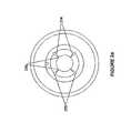
- FIG. 1 apresents a perspective view of a removable multi-channel applicator of the present disclosure including an applicator nozzle.
- the nozzleis depicted as operatively attached to a transducer of an ultrasound wound therapy device and with a fluid container coupled thereto.
- FIG. 1 bpresents a perspective view of the removable multi-channel applicator of an alternative embodiment including an applicator nozzle and an applicator nozzle face.
- the applicatoris operatively attached to a transducer of an ultrasound wound therapy device and with a fluid container coupled thereto.
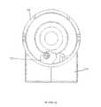
- FIGS. 2 a - cpresent an end view, a perspective view, and a profile view, respectively, of the removable multi-channel applicator of FIG. 1 b.
- FIG. 2 dpresents a cross sectional view of a removable multi-channel applicator of an alternative embodiment.
- FIG. 2 edepicts an end view of the removable multi-channel applicator of FIG. 1 b.
- FIG. 3presents a perspective view of a removable multi-channel applicator of the present disclosure interconnected to a generator-pump unit 400 .
- the applicatoris depicted just prior to being operatively attached to a transducer of an ultrasound wound therapy device and with a fluid container coupled thereto.
- FIGS. 4 a - bpresent perspective views of a plurality of removable multi-channel applicator nozzles of alternative embodiments.
- FIG. 5presents a perspective view of a removable multi-channel applicator nozzle of another alternative embodiment.
- FIGS. 6 a - cpresent an end view, a perspective view, and a profile view, respectively, of a removable multi-channel applicator nozzle of yet another alternative embodiment.
- FIGS. 7 a - bpresent alternative embodiments of a removable multi-channel applicator nozzle.
- FIG. 7 c - dpresent perspective views of fluid flow pathways of the removable multi-channel applicator shown in FIG. 7 b
- FIG. 8 apresents a perspective view of a transducer assembly showing a groove for receiving a tubing.
- FIG. 8 bpresents a perspective view of the transducer assembly shown in FIG. 8A with the tubing in place.
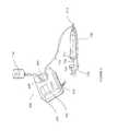
- FIG. 9 apresents a perspective view of a removable multi-channel applicator of an alternative embodiment operatively attached to a transducer of an ultrasound wound therapy device.
- FIG. 9 bpresents a cross-sectional view of a portion of the removable multi-channel applicator shown in FIG. 9 a.
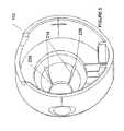
- FIG. 10 a - bpresent perspective views of a plurality of applicator nozzle faces of alternative embodiments.
- distalrefers to that portion which is farthest from the operator while the term “proximal” refers to that portion which is closest to the operator.
- proximalrefers to that portion which is closest to the operator.
- distalalso refers to that portion which is closest to the patient or other surface being treated.
- woundrefers to surface wounds, such as bums and skin lesions; internal wounds, such as ulcers and surgical cuts due to surgery; surgical incisions; injuries, including broken bones; and other conditions or applications requiring treatment using ultrasound wound therapy.
- the term “applicator”is used to refer to an applicator nozzle (also referred to as a nozzle).
- an applicator nozzlealso referred to as a nozzle
- the term “applicator”refers to the interconnected unit of an applicator nozzle and nozzle face.
- the terms “applicator”, “nozzle”, and “applicator nozzle”are synonymous and can be used interchangeably.
- nozzleor “applicator nozzle” is used to refer to a nozzle body comprising a plurality of channels combined with one or more of a nozzle liner; a passageway defined by a space between the nozzle body and the nozzle liner; and an opening for introducing fluid to the plurality of channels.
- the “nozzle”comprises a nozzle body comprising a plurality of channels and an opening for introducing fluid to the plurality of channels.
- the “nozzle”comprises a nozzle body comprising a plurality of channels; a nozzle liner; and an opening for introducing fluid to the plurality of channels.
- the “nozzle”comprises a nozzle body comprising a plurality of channels; a nozzle liner; a passageway defined by a space between the nozzle body and the nozzle liner; and an opening for introducing fluid to the plurality of channels.
- an applicatoras described herein, is interconnected with an ultrasound wound therapy device and used to deliver ultrasound energy (in the presence or absence of a liquid spray) to patient tissue.
- ultrasound energyin the presence or absence of a liquid spray
- the ultrasound energy (and liquid spray, if present)is delivered without contact between the applicator and the patient tissue being treated.
- the ultrasound energy (and liquid spray, if present)are delivered from a non-contact distance. Once delivered, the ultrasound energy penetrates the treated tissue to provide a therapeutic effect.
- the ultrasound energy deliveredis low frequency ultrasound energy. In certain embodiments, the ultrasound energy delivered is low intensity.
- low frequency ultrasoundis delivered (in the presence or absence of a liquid spray) from a non-contact distance and without causing a substantial increase in the temperature of the treated tissue.
- the treatment of certain conditionsit may be preferable to have treatment conducted in a hospital or doctor's office so that a health care professional can monitor the duration and course of the treatment. Under certain circumstances, however, it may be preferable to allow the patient to be treated at home—either by a visiting health professional or by the patient himself.
- treatingis meant to include decreasing or eliminating one or more symptoms of a condition or disorder.
- low frequency ultrasound energyis administered (with or without a liquid spray) to effected tissue of a patient in need thereof.
- the low frequency ultrasound energyis administered without contact between the effected tissue and the ultrasound transducer or other components of the device (non-contact distance).
- the low frequency ultrasound energypenetrates the tissue to provide a therapeutic effect. Regardless of the mechanism of action of the ultrasound energy, these methods can be effectively used to treat patients.
- Ultrasound energycan be delivered alone. Such methods are often referred to as delivering ultrasound “dry”.
- the methodcomprises delivering low frequency ultrasound alone (from a non-contact distance) and in the absence of a liquid spray or other coupling agent. When used in this way, the ultrasound energy penetrates, for example, the tissue to provide a therapeutic effect. Over one or more treatments, improvement in a patient's condition can be observed.
- the ultrasound energyis low frequency ultrasound energy.
- ultrasound energycan be delivered via a liquid spray.
- Such methodsare often referred to as delivering low frequency ultrasound “wet”.
- a combination of ultrasound energy and a liquid sprayis delivered (from a non-contact distance) to the tissue.
- the energy, and to some extent the liquid spraypenetrate the tissue to provide a therapeutic effect.
- Exemplary liquids that can be used to generate a liquid sprayinclude saline or water.
- the liquids used to generate the spraycan themselves be (or contain) a therapeutic agent, such as an antibiotic, analgesic, antiseptic, and the like.
- the ultrasound energyis low frequency ultrasound energy.
- the methodcomprises very local delivery of ultrasound energy (in the presence or absence of a liquid spray) to effected tissue.
- the goalis to treat, to the extent possible, only effected tissue and not asymptomatic tissue.
- the methodcomprises local delivery that includes effected tissue, as well as adjacent tissue—even if such adjacent tissue is asymptomatic. The patient's health professional can select the appropriate treatment approach, including the number of treatments, the duration of each treatment, and whether the treatment should be “dry” or “wet”.
- the method of delivering ultrasound energy (whether “wet” or “dry”) using the systems and applicators provided hereinis used as part of a therapeutic regimen combining one or more additional treatment modalities.
- additional modalitiesinclude, but are not limited to, negative pressure therapy, topical anti-bacterial ointments, systemic antibiotics, silver-based creams, and dressings.
- the methods of the present inventionmay be used in combination with physical therapy, occupational therapy, psychological therapy, diet, and exercise.
- the various treatment modalitiescan be administered/used a single time or multiple times and can be administered/used prior to, following, or during delivery of ultrasound energy.
- the one or more additional treatment modalitiescomprises applying a topical medicament to the patient (e.g., to the wound or surface to be treated) prior to and/or following delivering said ultrasound energy to the wound or surface to be treated.
- the method for treating a patientcomprises a single treatment.
- the method for treating a patientcomprises multiple treatments.
- patientsmay receive doses of ultrasound two or more times per week (e.g., 2, 3, 4, 5, 6, 7 times per week), for one, two, three, four, or more than four weeks.
- the appropriate number of treatments, and the duration of each treatmentcan be determined by a health care provider based on, for example, the particular condition being treated, the severity of the condition, and the overall health of the patient. Furthermore, the health care provider can determine whether treatment should be “wet” or “dry”.
- the low frequency ultrasound energy deliveredis approximately 10-100 kHz, approximately 20-80 kHz, approximately 20-40 kHz, approximately 35-60 kHz, or approximately, 40-50 kHz.
- the frequencyrefers to the frequency at which the transducer tip portion of the ultrasound transducer vibrates.
- the ultrasound energyis delivered at a frequency of approximately 10-100 kHz, approximately 20-80 kHz, approximately 20-40 kHz, approximately 35-60 kHz, or approximately, 40-50 kHz.
- the ultrasound energyis delivered at a frequency of approximately 30-35 kHz, approximately 35-40 kHz, or approximately 40-45 kHz.
- the ultrasound energyis delivered at a frequency of approximately 40 kHz.
- the low frequency ultrasound energyis also low intensity ultrasound energy. Intensity refers to the amount of energy transferred to the tissue. In certain embodiments, the low frequency, low intensity energy has an intensity of approximately 0.1 to 2.2 W/cm 2 . Stated another way, in certain embodiments, the invention contemplates delivering low frequency ultrasound energy so as to provide a certain energy level to patient tissue. In certain embodiments, the ultrasound energy level provided to patient tissue is approximately 0.1-1.0 watts/cm 2 . In certain other embodiments, the ultrasound energy level provided to patient tissue is approximately 0.1-0.7 watts/cm 2 .
- non-contact distance between the distal most surface of the applicator (either the distal most end of the nozzle or, when present, the distal most end of the nozzle face) and the tissue or surface being treatedis a non-contact distance of at least 0.1 inches (2.5 mm). In other embodiments, the non-contact distance is from about 2.5 mm to about 51 cm. In other embodiments, the non-contact distance is from about 15 mm to about 25 mm. Regardless of the exact distance, non-contact treatment means that there is no contact between the applicator and the effected tissue or surface that is being treated. It should be noted that non-contact refers to the absence of contact with the tissue or surface that is being treated.
- components of the applicator or devicemay contact the tissue or surface that is not being subjected to treatment.
- a handle of the devicemay be affixed to a patient's arm, thereby alleviating the need for an operator to hold the device throughout treatment. Such contact with other patient tissue that is not being subjected to treatment does not alter the characterization of the treatment as “non-contact”.
- the low frequency ultrasound energydoes not significantly decrease the viability of human cells of the effected tissue.
- the low frequency ultrasound energy delivered from a non-contact distance via the subject applicatorsis non-thermal. In other words, delivery of the ultrasound energy (and optionally liquid spray) does not cause a significant increase in the temperature of the treated patient tissue (e.g., does not increase the temperature of the treated patient tissue by more than approximately 1° F.).
- any of the applicator designs disclosed hereincan be used, for example, with an ultrasound device.
- the applicatorin operation with an ultrasound device, the applicator is interconnected to a transducer assembly, and the transducer assembly is operably interconnected to a generator, thereby providing an ultrasound treatment system.
- the applicatorPrior to use “wet”, the applicator is interconnected or otherwise placed in fluid communication with a fluid source. In this way, fluid is provided to the applicator and, in turn, provided to a portion of the transducer tip.
- ultrasound energy and a fluid sprayis delivered from a distal end of the applicator.
- the applicatoris chosen to deliver fluid from a fluid container to a plurality of sections of the transducer tip portion.
- any of the applicator designs disclosed hereincan be used in a therapeutic method to deliver ultrasound energy and/or a liquid spray to patient tissue.
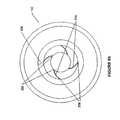
- FIG. 1 aillustrates, among other components, an applicator 100 having a nozzle 102 ( FIGS. 2-6 ).
- the applicator 100further includes a nozzle face 104 ( FIGS. 2 c and 10 a - b ) that is coupled to the applicator nozzle 102 .
- the nozzle 102includes a proximal region 202 , a distal region 204 , a nozzle body 206 , a nozzle liner 208 , a connector 210 , a distal nozzle opening 212 , and a plurality of fluid channels 214 .
- the proximal region 202 of the nozzle body 206has a larger diameter than the distal region 204 , such that the nozzle body 206 has a truncated conical shape.
- the nozzle body 206is symmetrical about the its center axis (not shown).
- the applicatorincludes a nozzle face 104 .
- applicators without a nozzle face 104are similarly contemplated and are depicted, for example, in FIG. 1 a .
- the nozzle face 104includes a proximal region 216 , a distal region 240 , and a distal nozzle face opening 220 .
- nozzles 102having different number of channels, channel shapes, and channel dimensions are provided, respectively.
- nozzle faces 104having different sizes and shapes are provided.
- FIGS. 9 a - bdepict an alternate embodiment of the applicator 100 without the nozzle face 104 .
- the applicator 100 of the present disclosureis designed for use with an ultrasound wound therapy device, such as the device described in U.S. Pat. No. 6,569,099, the entire content of which is incorporated herein by reference.
- an ultrasound wound therapy devicesuch as the device described in U.S. Pat. No. 6,569,099, the entire content of which is incorporated herein by reference.
- the present disclosureis also related to U.S. Pat. Nos. 6,478,754 and 6,663,554 and U.S. patent application Ser. Nos. 09/684,044 and 11/473,934, the entire content of both patents and both patent applications is incorporated herein by reference.
- the foregoing patents and applicationsteach that delivery of ultrasound energy and a liquid mist to a wound, such mist generated by contacting a vibrating ultrasound transducer with drops of liquid, promotes wound healing and decreases the healing time of wounds. More specifically, liquid is delivered to a vibrating tip portion of an ultrasound transducer to generate a liquid mist.
- the ultrasound energy and/or liquid mistpenetrate the tissue to a beneficial depth to provide a therapeutic effect even though the energy is provided to the wound at a non-contact distance (e.g., without contact between the ultrasound transducer and the patient or wound). Additionally, and without being bound by theory, the ultrasound energy and/or liquid mist provide a therapeutic effect at the tissue surface.
- the foregoing patents and applicationsprovide various ultrasound transducers and transducer assemblies, treatment algorithms, and exemplary nozzle and fluid delivery designs. Furthermore, the foregoing patents and applications teach the delivery of numerous fluids including, but not limited to sterile water, saline solution (including sterile saline solution), antibiotics, antifungal agents, growth factors, and other medicaments.
- the liquidconsists essentially of saline solution, such as sterile saline solution.
- saline solution that does not contain a therapeutic medicamentis the liquid delivered.
- the present inventionprovides an alternative applicator for use with the ultrasound wound therapy methods, transducers, assemblies, and other components disclosed in the foregoing patents and applications.
- the inventioncontemplates combinations of any of the aspects and embodiments of the applicator and fluid container disclosed herein with any of the aspects and embodiments of the ultrasound wound therapy methods, transducers, assemblies, and other components disclosed in the foregoing patents and applications.
- the present disclosurecontemplates that the applicator provided herein may be used in other methods of treating patient tissue and/or in combination with other devices or systems for delivering ultrasound and/or fluid to patient tissue.
- FIGS. 1 a - billustrate an exemplary ultrasound wound therapy device having an applicator 100 connected to a transducer assembly 108 , which, in turn, operatively connects to a generator 110 .
- the generator 110includes various components necessary to supply power to the transducer assembly 108 .
- the visible portion of the transducer assembly 108is the plastic housing of the transducer assembly.
- the actual transducer, from which the transducer tip portion (the portion of the transducer contacted with fluid in operation) extends distallyis not visible in these drawings.
- the transducer tip portionis not visible in FIG. 1 a , but can be seen in the views depicted in FIGS. 3 , 9 a , and 9 b.
- the generator 110may also contain a graphical user interface (GUI) for displaying information helpful to the operator.
- GUIgraphical user interface
- the generator 110consists of three major functional sections: the AC MAINS, the main board, and the GUI board.
- the AC MAINSis connected to an appliance inlet with a hospital grade detachable power cord.
- the appliance inletis a power entry module listed for medical applications.
- the appliance inletis a power entry module with an 115V/230V voltage selection, and is designed to operate on 115V ac and 60 Hz (e.g., for operation in North America) or 230V ac and 50 Hz (e.g., for operation in Europe).
- the MAIN boardconverts the secondary output voltage from the MAINS transformer to the low voltage power rails for the internal electronics and the drive voltage for the drive electronics to the transducer assembly 108 .
- the MAIN boardcontains a microprocessor that controls, measures, and monitors the drive electronics.
- the transducer assembly 108connects to the MAIN board.
- the microprocessorreferred to as the engine, monitors the performance of the system and communicates the information to a second microprocessor located on the GUI board.
- the enginecommunicates to the second microprocessor via a RS-232 communication link.
- the electronicsdrive the ultrasound portion of the drive electronics with a push-pull converter that has a feedback loop with a Phase Locked Loop (PLL) to track the center frequency of the ultrasound components.
- PLLPhase Locked Loop
- the GUI boardprovides the graphical user interface for the operator.
- a custom membrane switch panel with, for example 6 keys,allows the operator to select the functions and operating parameters of the system.
- a purchased graphical LCD displayconnected to the GUI board, can be used to display information to the operator. For example, information about the system's status, mode of operation, and treatment time can be displayed via the GUI.
- the GUImay have a back light generator for the LCD on it.
- the GUI microprocessorruns the system by controlling the human interface and running the various algorithms to control the operation of the system. For example, a treatment algorithm can be run on the GUI microprocessor.
- the ultrasound wound therapy devicemay include one or more of a timer to record total treatment time, a timer to count-down from a selected treatment time to zero, and an alarm to indicate that the total treatment time has elapsed or that there is a problem with some component of the device.
- FIG. 1 adepicts an applicator 100 having a nozzle 102 .
- the applicator 100may also include a nozzle face 104 coupled to the nozzle 102 from the distal region 204 of the nozzle. Details regarding the nozzle face 104 of the applicator 100 will be described in greater detail with regard to FIGS. 10 a - b .
- the applicator 100mechanically engages with the transducer assembly 108 of an ultrasound wound therapy device.
- a proximal portion 202 of the nozzle 102slides over a distal portion 702 of the transducer assembly 108 .
- a plurality of aligning slots (not shown) of the nozzle 102may be provided to engage with a plurality of aligning pins (not shown) of the transducer assembly 108 .
- the inventionspecifically contemplates that the applicator 100 is removable and can be reversibly mated to the transducer assembly.
- all or a portion of the applicator 100is disposable. In other words, all or a portion of the applicator 100 is intended to be used once, and then discarded. In other embodiments, all or a portion of the applicator 100 can be sterilized following use, and re-used. For example, all or a portion of the applicator 100 can be autoclavable or gamma-irradiatable.
- FIGS. 1 a - balso show a switch 112 a that may control one or more of the power supplied to the transducer assembly 108 , the flow of fluid, or the fluid flow rate. Also shown is a fluid source 114 and tubing 116 that interconnects the fluid source 114 to the nozzle 102 via a connector 210 . As depicted, the connector comprises an opening in communication with the plurality of channels in the interior of the nozzle body, such that fluid can flow from the fluid source to the plurality of channels.
- a transducer tip portionextends distally from the transducer assembly.
- the transducer tip portionis sometimes referred to in the literature as a horn.
- the transducer tip portionvibrates and emits the ultrasound energy.
- the nozzleis used to deliver ultrasound energy and a liquid spray.
- the vibrating tip portion of the ultrasound transduceris contacted with liquid, thereby generating a liquid spray.
- the applicators of the present inventionare used to deliver liquid essentially simultaneously to a plurality of positions on the tip portion of the ultrasound transducer (on the transducer tip portion).
- an applicator or other means to deliver liquid to the vibrating transducer tip portion at a plurality of positionsis in contrast to previous methods where liquid was delivered to the transducer tip portion via a single initial point of contact.
- an applicator or other mechanism to deliver liquid to the transducer tip portion via a plurality of initial points of contactis in contrast to prior designs where liquid was dripped on the transducer tip portion via a single fluid opening or flowed through an orifice in the transducer itself.
- the ultrasound energy and liquid sprayare then delivered to the wound via the distal nozzle opening.
- the nozzleis used to deliver ultrasound energy alone, in the absence of a liquid spray or coupling agent.
- the nozzleis used to deliver ultrasound energy in the absence of a liquid spray or coupling agent.
- the transducer tip portionis shielded by the applicator such that neither an operator nor a patient can readily contact the transducer tip portion.
- the entire transducer tip portion, including the distal most end,is shielded by the applicator once the applicator is interconnected to the transducer assembly (See, elements 706 and 704 of FIG. 9 ).
- the distal most portion of the transducer tipis proximal to the distal most tip of the applicator, when the applicator is interconnected to the transducer assembly.
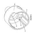
- FIGS. 2 a - cillustrate an exemplary applicator 100 including a multi-channel applicator nozzle 102 and a nozzle face 104 .
- the nozzle 102includes a connector 210 , a nozzle liner 208 , a nozzle body 206 coaxially disposed around the nozzle liner 208 , and a distal nozzle opening 212 defined by a distal end of the nozzle body 206 .
- the nozzle 102also includes a plurality of channels 214 in the interior surface 222 of the nozzle body 206 . These channels may be injection molded in place during the manufacture of the nozzle. In some embodiments, the channels may be etched or machined.
- the nozzle body 206 and the nozzle liner 208may be injection molded using thermoplastic ABS (Acrylonitrile-Butadiene-Styrene).
- the connector 210is oriented on an axis substantially perpendicular to a longitudinal axis of the nozzle 102 and is configured to permit introduction of a fluid, such as saline, into the interior of the nozzle 102 .
- the connector 210may be sized and shaped to interconnect with a flexible or a rigid tubing or a cartridge to facilitate fluid flow from a fluid source to the connector.
- the connector 210extends from the exterior of the nozzle body 206 to an opening 224 on the interior surface 222 of the nozzle body 206 .
- the nozzle liner 208which may have a truncated conical shape, is snap fitted to the nozzle body 206 , which may also have a truncated conical shape.
- a spaceis created between the nozzle liner 208 and the nozzle body 206 .
- a passageway 228is defined by this space. The space is enclosed by the nozzle liner 208 and the nozzle body 206 .
- the passageway 228has a ring shape with a triangular cross section (shown in FIG. 2C ) and encircles a portion of the nozzle liner 208 .
- the opening 224 of the connector 210opens into the passageway 228 .
- the fluidenters the passageway 228 through the opening 224 and fills the passage 228 .
- the tight fit created between the nozzle liner 208 and the nozzle body 206prevents the fluid in the passageway 228 from leaking out of the passageway 228 .
- Connector 210is one example of a means for providing fluid from outside the nozzle body to an opening that is in fluid communication with the plurality of channels.
- FIG. 2 dshows a cross sectional view of the inlets 226 of the channel 214 being in contact with the passageway 228 .
- the pressurized fluidfills the enclosed passageway 228 , the fluid flows into the multiple channels 214 through the respective inlets 226 of the channels 214 .
- the fluidWhen the fluid exits from the plurality of channels 214 via respective channel outlets 230 , the fluid contacts a tip portion 706 of the transducer assembly 108 at multiple sections around a circumference of the tip portion 706 .
- the inlets 226 and outlets 230 of the channels 214may be appropriately sized to allow an even coating around the entire circumference of the tip portion 706 .
- the tip portion 706 of the transducer assembly 108wicks the fluid around its circumference.
- having a plurality of evenly spaced channels 214 around the circumference of the tip portion 706 of the transducer assembly 108may shorten the time needed for the fluid to coat the circumference of the tip portion 706 before the transducer assembly 108 is activated.
- almost no timeis delayed for the fluid to fully coat the tip portion 706 of the transducer assembly 108 .
- the connector 210 of the nozzle 102is configured to receive the fluid into the interior of the nozzle 102 .
- the fluidis pressurized to enter the nozzle 102 via the connector 210 once a user unclamps the tubing 116 that interconnects the fluid container 114 to the connector 210 or otherwise begins the flow of fluid from the fluid container 114 .
- Such unclampingcan be performed manually by the user.
- a peristaltic pumpis used.
- a peristaltic pumpat least includes a rotor and rollers or other tube-engaging members movable within a housing relative to the clamped flexible tubing.
- a peristaltic pumptypically includes between four to six rollers. The rollers compress the clamped flexible tubing.
- FIG. 3shows a fluid container 114 , a tubing 116 , an applicator 100 , and a generator-pump unit 400 .
- the generator-pump unit 400includes, among other things, a generator portion 402 , a pump portion 404 , multiple rollers 406 , an LCD display 408 , and a connection inlet 410 .
- the generator portion 402may automate the fluid to enter the nozzle by, for example, regulating a valve (not shown) coupled to the tubing 116 .
- the pressure applied to the fluidmay be automatically maintained by the generator 402 based on values supplied by the user from a user interface, such as a dial, coupled to the generator 402 .
- the generator 402may report to the user the monitored pressure readings in the LCD display 404 of the generator 402 .
- the generator-pump unit 400may include an outer cover to protect the rollers 406 and the flexible tubing.
- all or a portion of the flexible tubing and/or fluid containermay be housed with the generator-pump unit 400 , rather than provided external to the generator-pump unit 400 .
- the generator-pump unit 400is fully integrated such that it performs all of the functions of the generator 110 depicted in FIG. 1 a.
- the pressurized fluidis delivered to the connector and to the nozzle at a constant flow rate regardless of the quantity of fluid in the fluid container, the angle or orientation of the transducer assembly 108 or applicator 100 , or the position of the fluid container 114 relative to the transducer assembly 108 .
- a pressurized delivery systemsuch as a peristaltic pump may allow the connector 210 to be placed at any angle or orientation relative to the nozzle 102 .
- the center axis defined by the connectormay be substantially perpendicular, parallel or at an angle in relation to the longitudinal axis of the nozzle.
- the connectormay be placed upright in relation to the transducer assembly, as depicted in FIGS.
- the pressuremay be similar to the pressure of the fluid under a gravity-fed condition.
- the pressure applied to the fluidmay be influenced by the sizes and/or shapes of the channel outlets 230 ( FIG. 2A ).
- the circumference of the nozzle 102decreases distally.
- the diameter of the distal opening 212 of the nozzle 102may be smaller than the diameter of the proximal portion 202 of the nozzle 102 .
- the diameter of the distal opening 212 of the nozzle 102is approximately 60% the diameter of the proximal portion 202 .
- the diameter of the distal opening 212is approximately 50%, 40%, 33%, 30%, 27.5%, or 25% the diameter of the proximal portion.
- FIGS. 4 a - 2 cprovide exemplary nozzle structures 102 having three and five straight channels 214 , respectively. It is envisioned that the channels are arranged in a radially symmetrical position with respect to the center axis of the nozzle body 206 . In other embodiments, the channels 214 may be dispersed at varying distances from one another. In other words, the channels 214 are asymmetrical about the center axis of the nozzle body 206 .
- the number of channels 214 in a nozzle 102may affect the resulting spray pattern.
- the three- and four-channel nozzles 102may produce more consistent spray patterns than nozzles 102 having a higher number of channels 214 .
- a nozzle 102 having more than four channels 214needs to be offset with a reduced fluid flow rate in each channel 214 in order to achieve a flow rate equivalent to that produced by a single-channel nozzle 102 .
- the reduced flow ratemay lead to a reduction in the quality of liquid mist formation and may increase the amount of fluid that drips from the applicator 100 .
- nozzles having greater than four channels or less than three channelsare also contemplated.
- the fluid flow ratecan be appropriately adjusted based on the number of channels included in the nozzle body.
- the nozzle bodyincludes 2 channels, 3 channels, 4 channels, 5 channels, or 6 channels.
- the plurality of channelsmay be evenly spaced or asymmetrically dispersed.
- the plurality of channelsare etched, molded, or otherwise presented on the interior surface of the nozzle body. However, it is also contemplated that all or a portion of the plurality of channels may extend or be present on an exterior surface of the nozzle body.
- FIG. 5shows the diameter of an inlet 226 of a channel 214 being larger than the diameter of an outlet 230 of the channel 214 .
- the cross-sectional channel sizeis approximately uniform throughout the entire length of the channel 214 .
- the restriction on cross-sectional channel sizemay also be implemented to compensate for the usage of a pressurized system.
- the nozzle bodyincludes a plurality of channels, each of which has the same or approximately the same cross-sectional channel size. In other embodiments, at least one of the plurality of channels has a cross-sectional channel size that differs from at least one other of the plurality of channels.
- an exemplary nozzle structure 102 having four spiral-shaped channels 214is provided. These channels may be arranged by following a curve (not shown) on the interior surface of the nozzle body 206 that winds about the center axis (not shown) at a continuously decreasing distance from the center axis.
- the inlets of the channelsmay be evenly spaced from one another.
- the outlets of the channelsmay be evenly spaced from one another.
- the inventioncontemplates unevenly spaced inlets and/or outlets of the channels. Regardless of the number and spacing of the channels, the invention contemplates the use of channels of varying shapes and dimensions.
- the multiple channelscan each be of the same shape and dimension or can be of differing shapes and/or dimensions.
- the flow rate of the fluidmay be controlled by the diameter of the inlets and outlets of the channels and/or the applied fluid pressure.
- the diameter of the inlet and the outlet of the channelmay be reduced to minimize the amount of fluid that drips from the applicator 100 .
- the applied fluid pressuremay be increased to maintain the flow rate with the reduced diameter of the channel.
- the diameter of the connector opening 224 of the connector 210may be about 0.035 inches or greater. In certain embodiments, the diameter may be about 0.08 inches. It is envisioned for the diameter of the channel inlets 226 to be about 0.05 inches. In certain embodiments, the diameter of the channel outlets 230 may vary with the number of channels in the nozzle. For example, the diameter of the channel outlets 230 for the four-channel nozzle design of FIG. 2 may be about 0.01 inches. In addition, the diameters of the channel outlets 230 for the three-channel nozzle of FIG. 4 a , five-channel nozzle of FIG.
- the dimension of the channel outletsis inversely proportional to the number of channels in the nozzle.
- a combination of the aforementioned sizes for the connector opening 224 , the channel inlets 226 and the channel outlets 230may generate relatively uniform particle sizes of fluid.
- the particle sizesmay be approximately equal to 60 ⁇ m in diameter.
- the approximately uniform sized particlesmay be approximately equal to 40 ⁇ m, 45 ⁇ m, 50 ⁇ m, 55 ⁇ m, 60 ⁇ m, or 65 ⁇ m in diameter.
- the diameter of the distal opening 220 of the nozzle face 104is about 1.00 inch.
- the foregoing measurementsare exemplary, and other operable combinations of sizes and shapes are similarly contemplated.
- FIG. 7Ashows alternative embodiments of the nozzle liner 308 and the nozzle body 306 .
- the nozzle liner 308includes, among other things, a tubing connection port 304 , a cover 302 , an outer surface 310 .
- the tubing connection port 304is another variation of a connector 210 and provides another means (opening) by which fluid may flow from the exterior of the applicator to the plurality of channels.
- the opening that is in fluid communication with the plurality of channelscomprises a connector or a connection port.
- the connector or connection portmay be located in any place and at any angle relative to the nozzle body.
- the connector or connection portare rigid and are made of the same material as the nozzle body and/or nozzle liner. In other embodiments, the connector or connection port are flexible.
- the opening by which fluid may flow from the exterior of the applicator to the plurality of channelsmay be an opening in the nozzle body or an opening in the nozzle liner.
- the nozzle liner 308in some embodiments, includes a snap-fit locking feature (not shown) to create a snap-fit between the nozzle liner 308 and the nozzle body 306 .
- the nozzle body 306includes horizontal walls 314 for receiving the nozzle liner 308 as shown in FIG. 7B .
- the nozzle body 306also includes a fluid path groove 320 for receiving the fluid. The fluid from the tubing 116 flows into the tubing connection port 304 and travels vertically in the fluid path groove 320 . The fluid then flows into the space 326 ( FIG. 7D ) defined by the cover 302 and an inner rim 322 of the nozzle body 306 .
- the space 326results when the horizontal portion 324 of the cover 302 is positioned against the inner rim 322 having a radius.
- the fluidthen flows from the space 326 to the passageway (not shown) created between the nozzle liner 308 and the nozzle body 306 . From the passageway, the fluid enters the inlets 226 of the channels 214 as, for example, described above with regard to FIG. 2 .
- an openingfor example an opening in the connection port 304 , is in communication with the plurality of channels so that fluid may flow via the opening to the plurality of channels.
- the inlets 226may be aligned away from the space 326 ( FIG. 7D ). If a single inlet of the channel is in direct communication with the space 326 , the fluid may be unevenly distributed amongst the plurality of the inlets. Therefore, in some embodiments, the inlets 226 of the channels are positioned away from the space 326 . In certain embodiments, the passageway may have a similar cross-sectional shape as shown in FIG. 2 c . The fluid exits the channels 214 and coats the tip portion 706 of the transducer assembly 108 . As described above, embodiments of nozzle bodies comprising a plurality of channels having any of a number of sizes, shapes, and positions relative to each other are contemplated.
- the nozzle bodycomprises 2, 3, 4, 5, or 6 channels.
- the plurality of channelsis etched, embedded, or otherwise disposed on the interior surface of the nozzle body. In other embodiments, all or a portion of the plurality of channels extends to the exterior surface of the nozzle body.
- the nozzle body 306additionally includes a snap-fit indent (not shown) for locking the nozzle liner 308 in place.
- the nozzle liner 308may be welded to the nozzle body 306 to create a tight seal between the nozzle liner 308 and the nozzle body 306 .
- FIGS. 8A and 8Bshow the transducer assembly 108 having a groove 301 for placing the tubing 116 .
- the tubing 116is about 10 feet in length.
- the tubing 116is placed in the groove 301 along the transducer assembly 108 .
- the free portion of the tubing 116may be wrapped around the end of the transducer assembly 108 .
- the transducer assembly 108may also include a clip (not shown) or other equivalent device for holding the wrapped tubing 116 in place.
- having the tubing fitted to the transducer assemblyfacilitates the placement of the fluid container in any convenient location without being bound by the transducer assembly location. Having the tubing out of reach from a user may also minimize inadvertent damage to the tubing. In addition, the user may move and/or hold the transducer assembly with more freedom.
- FIG. 9 aillustrates an exemplary ultrasound wound therapy device having an applicator I 00 connected to a transducer assembly 108 .
- FIG. 9 bshows a cross-sectional view of a portion of an applicator 100 being connected to a transducer assembly 108 .
- FIG. 9shows a fluid container 114 coupled to the connector 210 of the nozzle 102 through the flexible tubing 116 .
- the transducer assembly 108is aligned and coupled to the nozzle 102 , for example, by aligning slots and pins or by a snap-fit.
- the distal end 704FIG.
- FIG. 9 balso shows a distal end 704 of the transducer tip portion 706 of the transducer assembly 108 extending longitudinally past the distal opening 232 of the nozzle liner 208 , but not to a location that is distal to the distal opening 212 of the nozzle 102 . That is, when the applicator 100 is engaged to the transducer assembly 108 , the distal end 704 of the transducer assembly 108 extends between the distal opening 232 of the nozzle liner 208 and the distal opening 212 of the nozzle 102 .
- the distal end 704 of the transducer assembly 108does not protrude out of the nozzle 102 (the distal end 704 of the transducer assembly 108 is proximal to the distal most portion of the applicator). In such embodiments, an operator or patient cannot inadvertently contact the transducer tip portion 706 . Given that the transducer tip portion 706 (including the distal end 704 ) vibrates during use, inadvertent contact with the vibrating transducer tip portion 706 may cause injury to a user or damage the device.
- a longitudinal separation distance 708shown in FIG. 9 b , between the distal end 704 of the transducer tip portion 706 of the transducer assembly 108 and the distal opening 212 of the nozzle 102 is specified to optimize fluid atomization.
- This longitudinal distance 708is hereinafter referred to as a “recess distance.”
- the spray patternmay cover a larger wound site area.
- the fluidis less likely to collide at the interior surface 208 of the nozzle 102 before exiting the nozzle 102 .
- the fluidmay be less likely to drip from the applicator 100 .
- the recess distanceis greater than 0.150 inches, the fluid may be more likely to collide with the interior surface 222 of the nozzle body 206 as it exits from the distal end 704 of the transducer assembly 108 .
- the recess distance 708may be about 0.06 inches or less.
- the recess distance 708may be about 0.05 inches or less.
- other recess distancesare possible and are within the scope of the present disclosure.
- a longitudinal separation distance 710 between the distal opening 232 of the nozzle liner 208 and the distal end 704 of the transducer assembly 108is also specified, hereinafter referred to as an “extension distance.”
- This extension distance 710specifies the location on the tip portion 706 of the transducer assembly 108 to which the fluid contacts after the fluid exits from the outlets 230 of the channels 214 ( FIG. 2 ).
- An optimized extension distance 710may maximize the range of motion for using the wound therapy device without compromising the quality of fluid atomization.
- an extension distance 710between about 0.03 inches and about 0.09 inches may allow the wound therapy device to be used in any orientation with respect to the wound site while still achieving an optimal spray pattern having minimal fluid dripping from the applicator 100 .
- a preferred extension distance 710may be between about ⁇ 0.065 inches and about 0.09 inches. It should be noted that a negative extension distance 710 implies that the distal end 704 of the transducer assembly 108 is proximal to the distal opening 232 of the nozzle liner 206 .
- a longitudinal separation distance between the distal end 704 of the tip portion 706 of the transducer assembly 108 and the surface or object to be sprayedis a non-contact distance of at least 0.1 inches (2.5 mm).
- the separation distanceis from about 2.5 mm to about 51 cm, more preferably, from about 15 mm to about 25 mm.
- the non-contact distancecan be similarly described as the distance between a distal-most edge 106 of the applicator 100 , and the surface or object to be sprayed.
- the non-contact distance from the distal-most edge 106 of the applicator 100 to the surface to be sprayedis at least about 2.5 mm or at least about 5 mm. In other embodiments, the non-contact distance from the distal-most edge 106 of the applicator 100 to the surface to be sprayed is from about 5 mm to about 15 mm.
- a nozzle face 104is further coupled to the wound therapy device.
- a nozzle face 104 of the applicator 100such as an energy reflector depicted in FIGS. 2 b - c , may be coupled to the distal nozzle opening 212 or distal end or distal portion of the nozzle 102 .
- the nozzle face 104is optional and is not required for use of the nozzle.
- the nozzle faceis detachable such that the applicator can be used with or without the nozzle face or can be used with a different nozzle face.
- the nozzle faceis permanently coupled to the nozzle.
- the nozzle and the nozzle facemay be cemented or otherwise affixed, or the nozzle and nozzle face may be molded or machined as a single unit.
- the nozzle face 104has a proximal region 216 , a distal region 240 , and a distal nozzle face opening 220 , where a diameter of the proximal region 216 of the nozzle face 104 is adapted to be smaller than a diameter of the distal region 240 .
- the nozzle face 104may serve as an energy reflector.
- the parabolic shape of the energy reflector nozzle face 104may help to create and/or maintain a standing wave pattern in a medium between the wound therapy device and a wound site.
- this standing wave patternmay be created based on the interference of the incident ultrasound waves delivered from the applicator 100 to the wound site and the waves reflected from the wound site.
- the creation and/or maintenance of a standing wave patternmay help prevent interference between the incident and reflected ultrasound waves.
- use of an energy reflectormay facilitate efficient delivery of more uniform ultrasonic energy.
- the parabolic energy reflector nozzle face 104may be interchanged with a different nozzle faces 104 for treating different types of wounds, which may require different patterns and/or coverage area of ultrasound energy contact.
- the proximal portion 216 of the nozzle face 104slides over a distal portion 204 of the nozzle 102 and is secured into place via, for example, aligning slots (not shown) and aligning pins (not shown) disposed over surfaces of the energy reflector 104 and the nozzle 106 , respectively.
- the nozzle face 104 and the nozzle 102may be coupled by a snap fit or a half-turn closure.
- Nozzle faces 104 of different shapes and sizesmay be used to provide different treatment conditions or to treat different types of wounds.
- a nozzle face 104may also further decrease the likelihood of inadvertent contact between the tip portion 706 of the transducer assembly 108 and a patient or an operator of the transducer assembly 108 .
- a nozzle face 104 having a parabolic shapesuch as the parabolic nozzle face 104 of FIG. 2 , is used to create a standing wave pattern in the medium between the transducer assembly 108 and the wound site, which focuses the delivery of high-density ultrasound energy to a specific treatment area.
- the nozzle face 104 depicted in FIG. 10 ais relatively flat and has a relatively small longitudinal extent.
- This nozzle face 104operates by dispersing low-density ultrasound energy over a treatment area that may be wider than the intended treatment area of the parabolic-shaped nozzle face 104 of FIG. 2 .
- a removable nozzle face 104may be attached to the distal nozzle opening 212 or distal end or distal portion of the nozzle 102 to focus the delivery of ultrasonic energy to a treatment area smaller than that of the parabolic-shaped nozzle face of FIG. 2 .
- the diameter of the proximal region 216 of the nozzle face 104is substantially larger than the diameter of the distal region of the nozzle face 104 .
- This nozzle face 104may be used to treat wounds in areas of the body that are difficult to reach, such as in a patient's ear, nose, mouth, or throat.
- the applicatorcomprises a nozzle interconnected to a nozzle face.
- the nozzle facemay be interconnected to the nozzle body via the distal opening, distal portion, or distal end of the nozzle body.
- the fluid containermay also be directly affixed to or housed within the transducer assembly.
- a disposable or re-fillable fluid cartridgemay be directly affixed to or housed within the transducer assembly.
- fluid flow to the applicatorcan be modulated with, for example, a clamp, a valve, a peristaltic pump, or the like.
- fluid flowis regulated by an on/off switch located on the transducer assembly or the generator.
- a single on/off switchcontrols fluid flow and the ultrasound transducer.
- separate switches or mechanismscontrol fluid flow and the ultrasound transducer.
- the fluid provided to and sprayed from the transducer assemblymay be of any appropriate carrier, such as saline, water (regular or distilled), or oil (such as a vegetable, peanut, or canola oil), optionally with a soluble pharmaceutical (e.g., an antibiotic), antiseptic, conditioner, surfactant, emollient, or other active ingredient.
- a soluble pharmaceuticale.g., an antibiotic
- the fluidcan also be a combination of two or more fluids and/or substances having microscopic particles, such as powder and the like.
- Exemplary fluidsinclude, but are not limited to, sterile water, saline solution, oil, oxygenated water, hypochlorous acid, or other isotonic or hypertonic solutions.
- Exemplary fluidsmay, in certain embodiments, further include drugs (e.g., therapeutic agents) such as antibiotics, anti-fungals, anti-virals, growth factors, analgesics, angiogenesis promoting agents, anti-inflammatory agents, narcotics, and the like, formulated in any of the foregoing fluids or in other pharmaceutically acceptable fluids appropriate for the formulation of the particular drug.
- drugse.g., therapeutic agents
- the fluiddoes not include a therapeutic drug.
- the fluidmay be sterilized so that, in use, a spray of a sterile solution can be administered to patients.
- the fluidfurther includes one or more preservatives appropriate for extending the shelf-life of the fluid.
- the applicatorcan be used “dry” to deliver ultrasound energy is the absence of fluid or other coupling medium. Regardless of whether the applicator is used to deliver ultrasound energy “wet” or “dry”, the applicator can be used to provide ultrasound therapy as part of a therapeutic regimen where one or more additional treatment modalities are also administered.
- the apparatusas described, is compatible for use with a pressurized system for delivering pressurized fluid to the transducer assembly 108 .
- An exemplary pressurized systemis depicted in FIG. 3 .
- the pressurized fluid delivery system of the present disclosurepermits the fluid to be supplied to the transducer assembly 108 from any location or orientation with respect to the body of the transducer assembly 108 .
- a gravity feed systemmay also be utilized with the devices of the present disclosure.
- the applicator 100may additionally include a cup that is designed to hold a fluid bottle in a relative upright position above the nozzle 102 .
- This cupmay be coupled to the nozzle 102 via the connector 210 which may include a valve structure for controllably supplying the fluid from the bottle to the nozzle 102 .
- a fluid bottle or other fluid sourcemay be directly interconnected to the connector or other opening in the absence of a cup, but optionally including a valve.
- An exemplary gravity-feed systemis described in detail in U.S. patent application Ser. No. 11/473,934, the entire contents of which is incorporated by reference herein.
- a fluid container 114 and a pressurized fluid delivery systemmay be advantageous for treating wounds for which having a bottle affixed to the applicator may interfere with accessing the particular wound site. It may also be useful to use the fluid container 114 and a pressurized fluid delivery system in situations where greater range of motion of the transducer assembly 108 is desired and/or where treatment requires the use of a larger quantity of fluid (i.e., the fluid container 114 may hold more fluid than the bottle).
- the term ‘greater range of motion’is meant to indicate that the operator has increased flexibility to effectively deliver treatment while holding the applicator and/or transducer assembly at any of a number of possible angles relative to the treatment surface.
- a fluid container of virtually any size or shapeis contemplated.
- the fluid containermay be placed on a counter-top, cart, or hung from a pole.
- the fluid containerrests or is affixed to the same cart upon which the ultrasound wound therapy device sits.
- the fluid containeris affixed to or housed within the generator.
- the applicators 100are disposable, and can be readily removed from the transducer assembly 108 and changed between patients or changed between each use even for the same patient. In certain embodiments, an applicator 100 is changed between each patient. Changing the applicator 100 between uses, such that each wound is treated with a fresh applicator 100 , prevents contamination between patients or between wound sites on the same patient.
- the applicator 100 and/or ultrasound wound therapy devicecontain means for encouraging or requiring that the applicator 100 be replaced following a single use.
- the applicator 100 and/or the ultrasound wound therapy devicecomprises means such that, once an applicator is engaged to a transducer assembly and then removed, the operator is prevented or discouraged from subsequently re-engaging the same applicator to a transducer assembly.
- Single use of the applicator 100is recommended by the manufacturer to prevent non-sterile use and/or cross-contamination between patients. For example, a message can be displayed by an LCD or other display located on the ultrasound wound therapy device to remind and encourage user compliance with the recommended use of the applicator 100 .
- the applicator 100 or ultrasound wound therapy devicemay include means for preventing nozzle re-use.
- the applicator 100 or ultrasound wound therapy devicemay include a mechanism that inhibits or prevents an operator from using a single applicator 100 to treat multiple patients and/or multiple wounds.
- Exemplary mechanisms for providing such preventive measuresincluding for example, an IC chip, a timer, an expanding foam, and/or a radio frequency tag 720 and corresponding radio frequency tag reader 722 ( FIG. 3 ), are described in detail in the U.S. patent application Ser. No. 11/473,934, the entire contents of which are incorporated herein by reference.
- the nozzle 102may include a locking device 730 ( FIGS. 2 c and 2 e ) to prevent re-coupling of the transducer assembly 108 to the applicator 100 .
- the locking device 730may be pre-assembled to the nozzle 102 and remain in a ready-to-be used position prior to use.
- the locking device 730shifts to an open position and remains in this position during the operation.
- the locking device 730shifts to a closed position. In the closed position, an arm 732 ( FIG.
- the liquid spray from the ultrasound wound therapy deviceprovides significant improvements for wound care and patient comfort during treatment.
- the fluid spray produced from the applicator 100has a uniform particle size, thus enhancing the efficiency with which the ultrasound energy is carried to the wound site.
- the non-contact distance from which the ultrasound energy and the fluid spray is delivered to the wound siteresults in beneficial effects including, but not limited to, decreased healing time, improved healing (e.g., more complete wound closure), and decreased incidence of infection. Without being bound by theory, this may be due to the ability of the emitted ultrasound energy and/or the fluid spray to penetrate the wound tissue to a beneficial depth. Additionally, action of the ultrasonic energy and/or the fluid spray at the wound surface may contribute to the therapeutic effect.
- the liquid spraymay be delivered at a temperature that does not result in substantial heating of the wound tissue, which minimizes aggravation of the wound.
- the ultrasound energy and/or fluid sprayis delivered without direct contact with the treated patient tissue and without significantly increasing the temperature of the treated tissue, patient tissue can be treated with little or no pain relative to any treatment modality that involves contact with the subject tissue.
- the applicator 100 or ultrasound wound therapy devicemay optionally be provided with a laser or ultrasonic transducer for measuring the non-contact distance or stand-off distance from a wound surface.
- a feedback control mechanismcan also be provided for indicating whether the measured non-contact distance is suitable for effecting optimum beneficial bactericidal, therapeutic and/or other effects.
- the feedback assemblyis integrated with the transducer assembly 108 and corresponding electronics housed within an ultrasonic generator 110 for obtaining the measured non-contact distance data and processing the data to determine whether the measured non-contact distance is optimum for treatment purposes. If the non-contact distance is determined not to be the optimum non-contact distance, the feedback control mechanism can sound an audible alarm or display a message on a display, such as an LCD display. The alarm or message can indicate if the non-contact distance should be decreased or increased. If the nozzle 102 /ultrasound wound therapy device is mounted to a robotic arm, the feedback control mechanism can in turn control the robotic arm for increasing or decreasing the non-contact distance.
- the delivery of ultrasonic energy and a fluid spray at a non-contact distanceimproves wound healing and decreases infection.
- emitted energy and the fluid sprayare applied to the wound.
- the energy and fluid sprayare applied for a treatment time proportional to the size of the wound.
- the approximate size of the woundcan be inputted into the ultrasound wound therapy device and the device sets a treatment time based on the size of the wound.
- the ultrasound wound therapy devicemay also be able to recommend an appropriate applicator nozzle face for providing the suitable ultrasonic energy pattern and/or intensity to treat such wound.
- treatment timesvary from approximately 5 minutes to approximately 30 minutes. However, shorter and longer treatment times are contemplated.
- the treatment timeis approximately 2 minutes or approximately 3 minutes.
- nozzle faces 104 of different sizes and shapesmay also be used to treat different types of wounds. For example, a small wound situated in an area of the body that is difficult to reach may be treated with a nozzle face 104 , as depicted in FIG. 10 b whereas a large surface wound may be treated with a nozzle face 104 , as depicted in FIG. 2 c.
- the operatorcan direct the energy and spray to the wound.
- the woundis treated by slowly moving the applicator 100 head back and forth and/or up and down (at a non-contact distance) across the wound.
- the spray patternmay be, for example, serpentine or substantially checkerboard in pattern.
- This delivery methodhas two advantages. First, this method helps insure that ultrasonic energy and liquid spray are delivered to the entire wound. Second, this method may help prevent operator fatigue that would likely result if the device was held in substantially the same place throughout the treatment. In one embodiment, the applicator 100 is held such that the ultrasonic energy and liquid spray are delivered substantially normal to the surface of the wound.
- the applicator 100can be held at any position or angle in relation to the surface of the wound.
- the spray patternmay include moving the applicator 100 in-and-out relative to the wound surface (e.g., varying the distance from the wound while maintaining a non-contact distance). Such a spray pattern helps ensure that a wound, which varies in depth across its surface area, is treated at an effective distance.
- the spray patternmay also be varied by using an appropriate nozzle face 104 designed to facilitate the production of certain spray pattern.
- the ultrasound energyis delivered in the absence of a liquid spray or coupling agent. Delivery of ultrasonic energy in the absence of a liquid spray or coupling agent is sometimes referred to herein as “dry” delivery.
- the treatment with ultrasound energyis part of a therapeutic regimen combining one or more additional treatment modalities.
- additional modalitiesinclude, but are not limited to, negative pressure therapy, topical anti-bacterial ointments, systemic antibiotics, silver-based creams, and dressings.
- the methods of the present inventionmay be used in combination with physical therapy, occupational therapy, psychological therapy, diet, and exercise. When used in combination with any topical medicaments, the topical medicament may be applied prior to and/or following treatment with ultrasound energy.
- the transducer assembly 108is affixed to a robotic arm programmed to direct the emitted energy and liquid spray to the wound.
- the emitted ultrasonic energy and fluid sprayare applied to the wound for a treatment time proportional to the size of the wound.
- the inventionprovides a treatment algorithm for selecting treatment time based on the size of the wound. The time for each treatment is selected based on the area of the wound. For example, the area of the wound is calculated by measuring the length of the wound (at its greatest point) and the width of the wound (at its greatest point and perpendicular to the length). The length and width of the wound can be measured, for example, in centimeters. The area of the wound (in square centimeters) is calculated by multiplying the length times the width of the wound.
- the treatment timeis proportional to the area of the wound. Similarly, treatment time may be calculated based on a treatment area when, for example, the area to be treated is not a wound or when treatment of an area that is larger or smaller than the actual wound is indicated.
- the following approximate treatment timesmay be selected based on wound size: 3 minutes for wounds with an area of less that 10 cm 2 ; 4 minutes for wounds with an area of 10-20 cm 2 ; 5 minutes for wounds with an area of 20-30 cm 2 ; 6 minutes for wounds with an area of 30-40 cm 2 ; 7 minutes for wounds with an area of 40-50 cm 2 ; 8 minutes for wounds with an area of 50-60 cm 2 ; 9 minutes for wounds with an area of 60-70 cm 2 ; 10 minutes for wounds with an area of 70-80 cm 2 ; 11 minutes for wounds with an area of 80-90 cm 2 ; 12 minutes wounds with an area of 90-100 cm.
- the ultrasonic wound therapy deviceis programmed with the algorithm.
- the operatorenters the wound size into the device using a keypad.
- a treatment timeis selected based on the wound size.
- the ultrasound wound therapy deviceincludes a timer that counts down from the treatment time. When the treatment time has elapsed (e.g., the timer has ticked down to zero), the ultrasound wound therapy device may automatically shut off. In other words, after the treatment time has elapsed, the power shuts off and the transducer stops vibrating. It is appreciated that a timer and automatic shut off mechanism have utilities apart from their use in conjunction with treatment times proportional to wound size.
- Such timersmay be used even in the absence of a treatment time algorithm (e.g., a timer can be used when the total treatment time is selected by the individual operator). Additionally or alternatively, an alarm may sound to alert the operator when the treatment time has elapsed.
- the above algorithmdoes not direct the frequency (total number or number/week) of treatments. Furthermore, as the wound heals, the treatment time may be reassessed and recalculated in accordance with the decreasing size of the wound. Additionally, the above treatment algorithm is only one way to select an appropriate treatment time. Wounds may be treated for a longer or shorter period of time than that recommended based on the treatment algorithm. Similarly, the generator can be modified to incorporate additional or alternative treatment algorithms.
- the above algorithmis merely exemplary.
- Other treatment algorithmscan be used based on, for example, the severity of the wound, the cause of the injury, the area of the body effected, and the health of the patient.
- other treatment algorithmsmay be appropriate when the applicator is used with an ultrasound therapy device, but for non-wound indications.
- an applicator 100can also be used in methods for treating tissue in which ultrasound energy is delivered in the absence of a liquid spray or coupling agent.
- the foregoing exemplary featuresincluding the use of a treatment algorithm, various means for preventing re-use of the applicator, and components for determining and maintaining the appropriate non-contact distance from the patient tissue, are equally applicable when the applicator is used in the absence of a liquid spray or coupling medium.
- kitscontemplates a variety of kits.
- a kitincludes one or more of an applicator 100 (e.g., a nozzle 102 , and optionally one or more nozzle faces 104 ), a fluid bag 114 , and flexible or non-flexible tubing 116 sized and shaped to interconnect the fluid bag 114 to the connector 210 of the nozzle 102 .
- the kitmay optionally include directions for use and/or one or more sterile swabs.
- the sterile swabscan be used to wipe, prior to or after use, one or more of: the fluid bag 114 , all or a portion of the applicator 100 , all or a portion of the tubing 116 , all or a portion of the transducer assembly 108 , and all or a portion of the ultrasound wound therapy device.
- the fluid bag 114includes a sterile fluid suitable for use in the treatment of a wound. Any of the foregoing kits may be sterilized prior to packaging such that the contents of the kit are sterile. The kits can be marked to indicate that they are intended for use with a single patient.
- the kitdoes not include the fluid bag 114 .
- the kitincludes the applicator nozzle and tubing, and the operator may use any appropriate fluid bag.
- the applicator 100includes a nozzle, a valve and a cup. This kit may be specifically intended for use in conjunction with a bottle.
- this applicator 100may be packaged with a bottle including a fluid, where the bottle is sized and shaped to fit onto the cup of the applicator 100 .
- This kitmay optionally include directions for use and/or one or more sterile swabs.
- Kits containing an applicator and any one or more of the foregoing kit componentsare contemplated. Additionally, kits can be packaged and/or sold alone or with an ultrasound therapy device.
Landscapes
- Health & Medical Sciences (AREA)
- Life Sciences & Earth Sciences (AREA)
- Surgery (AREA)
- Heart & Thoracic Surgery (AREA)
- Engineering & Computer Science (AREA)
- Biomedical Technology (AREA)
- Nuclear Medicine, Radiotherapy & Molecular Imaging (AREA)
- Medical Informatics (AREA)
- Molecular Biology (AREA)
- Animal Behavior & Ethology (AREA)
- General Health & Medical Sciences (AREA)
- Public Health (AREA)
- Veterinary Medicine (AREA)
- Surgical Instruments (AREA)
- Media Introduction/Drainage Providing Device (AREA)
Abstract
Description
Claims (39)
Priority Applications (1)
| Application Number | Priority Date | Filing Date | Title |
|---|---|---|---|
| US12/218,760US8491521B2 (en) | 2007-01-04 | 2008-07-17 | Removable multi-channel applicator nozzle |
Applications Claiming Priority (3)
| Application Number | Priority Date | Filing Date | Title |
|---|---|---|---|
| US87862107P | 2007-01-04 | 2007-01-04 | |
| US12/006,739US20080214965A1 (en) | 2007-01-04 | 2008-01-04 | Removable multi-channel applicator nozzle |
| US12/218,760US8491521B2 (en) | 2007-01-04 | 2008-07-17 | Removable multi-channel applicator nozzle |
Related Parent Applications (1)
| Application Number | Title | Priority Date | Filing Date |
|---|---|---|---|
| US12/006,739Continuation-In-PartUS20080214965A1 (en) | 2007-01-04 | 2008-01-04 | Removable multi-channel applicator nozzle |
Publications (2)
| Publication Number | Publication Date |
|---|---|
| US20090043248A1 US20090043248A1 (en) | 2009-02-12 |
| US8491521B2true US8491521B2 (en) | 2013-07-23 |
Family
ID=40347212
Family Applications (1)
| Application Number | Title | Priority Date | Filing Date |
|---|---|---|---|
| US12/218,760Active2028-05-03US8491521B2 (en) | 2007-01-04 | 2008-07-17 | Removable multi-channel applicator nozzle |
Country Status (1)
| Country | Link |
|---|---|
| US (1) | US8491521B2 (en) |
Cited By (2)
| Publication number | Priority date | Publication date | Assignee | Title |
|---|---|---|---|---|
| US20170143997A1 (en)* | 2014-01-30 | 2017-05-25 | Holly Elizabeth Rockweiler | Device and method to treat vaginal atrophy |
| US11224767B2 (en) | 2013-11-26 | 2022-01-18 | Sanuwave Health, Inc. | Systems and methods for producing and delivering ultrasonic therapies for wound treatment and healing |
Families Citing this family (14)
| Publication number | Priority date | Publication date | Assignee | Title |
|---|---|---|---|---|
| US8235919B2 (en)* | 2001-01-12 | 2012-08-07 | Celleration, Inc. | Ultrasonic method and device for wound treatment |
| US7914470B2 (en)* | 2001-01-12 | 2011-03-29 | Celleration, Inc. | Ultrasonic method and device for wound treatment |
| US20090177123A1 (en)* | 2007-12-28 | 2009-07-09 | Celleration, Inc. | Methods for treating inflammatory disorders |
| EP2231279A1 (en)* | 2007-12-28 | 2010-09-29 | Celleration, Inc. | Methods for treating inflammatory skin disorders |
| US20100022919A1 (en)* | 2008-07-22 | 2010-01-28 | Celleration, Inc. | Methods of Skin Grafting Using Ultrasound |
| USD674479S1 (en)* | 2010-09-29 | 2013-01-15 | Sound Surgical Technologies Llc | Handpiece for use in power assisted lipoplasty |
| CN105050527B (en)* | 2013-03-15 | 2018-03-27 | 圣纳普医疗(巴巴多斯)公司 | Intelligent positioning system and method therefor |
| US10413359B2 (en) | 2013-07-18 | 2019-09-17 | International Business Machines Corporation | Laser-assisted transdermal delivery of nanoparticulates and hydrogels |
| US9282803B2 (en)* | 2013-10-03 | 2016-03-15 | Donald John Ciervo | Ultrasonic cosmetic applicator |
| US9597702B1 (en)* | 2013-10-03 | 2017-03-21 | Sonaer, Inc. | Ultrasonic cosmetic applicator |
| WO2018022968A1 (en)* | 2016-07-29 | 2018-02-01 | Alliqua Biomedical, Inc. | Systems and methods for delivering cellular and biological materials using ultrasound for wound treatment and healing |
| USD897543S1 (en) | 2019-03-01 | 2020-09-29 | Madorra Inc. | Disposable component for vaginal ultrasound therapy device |
| USD976362S1 (en)* | 2019-09-12 | 2023-01-24 | Transportation Ip Holdings, Llc | Applicator nozzle |
| WO2023014118A1 (en)* | 2021-08-04 | 2023-02-09 | 주식회사 스킨그랩 | Skin care device for use in both ultrasonic delivery and drug application |
Citations (282)
| Publication number | Priority date | Publication date | Assignee | Title |
|---|---|---|---|---|
| US2534046A (en) | 1949-10-21 | 1950-12-12 | Johnson March Corp | Valve construction for proportioning devices |
| US2889852A (en) | 1957-03-11 | 1959-06-09 | James L Dunlap | Valve structures |
| US3207181A (en) | 1963-10-11 | 1965-09-21 | Willis N Elizabeth | Multiple orifice valve |
| US3243122A (en) | 1965-02-24 | 1966-03-29 | Alvin A Snaper | Ultrasonic spray apparatus |
| US3275059A (en) | 1965-05-10 | 1966-09-27 | Little Inc A | Nozzle system and fuel oil burner incorporating it |
| US3392916A (en) | 1965-12-08 | 1968-07-16 | Carl Gunnar Daniel Engstrom | Ultrasonic atomizer |
| US3433226A (en) | 1965-07-21 | 1969-03-18 | Aeroprojects Inc | Vibratory catheterization apparatus and method of using |
| US3504887A (en) | 1967-05-04 | 1970-04-07 | Itt | Flow control valves |
| US3522801A (en) | 1968-08-06 | 1970-08-04 | Hydrosonic Corp | Ultrasonic dental hygiene device |
| US3561444A (en) | 1968-05-22 | 1971-02-09 | Bio Logics Inc | Ultrasonic drug nebulizer |
| US3636947A (en) | 1970-12-03 | 1972-01-25 | Ultrasonic Systems | Ultrasonic home dental instrument and method |
| US3685634A (en) | 1970-06-08 | 1972-08-22 | Esab Hebe Ab | Conveyor belt for sheet metal |
| US3685694A (en) | 1969-12-18 | 1972-08-22 | Yan Nell Corp | Liquid dispenser plastic bottle and receptacle with piercing units |
| US3765606A (en) | 1971-04-02 | 1973-10-16 | Plessey Handel Investment Ag | Liquid-spraying devices having a nozzle subjected to high-frequency vibrations |
| US3860173A (en) | 1970-02-03 | 1975-01-14 | Naoyasu Sata | Non-polluting combustion engine having ultrasonic fuel atomizer in place of carburetor |
| US3874372A (en) | 1972-09-13 | 1975-04-01 | Bon Alain Le | Insert for ultrasonic medical device |
| US3952918A (en) | 1974-03-18 | 1976-04-27 | Highland Laboratories | Fluid dispenser apparatus |
| US4052004A (en) | 1975-02-19 | 1977-10-04 | Plessey Handel Und Investments A.G. | Vibratory atomizer |
| US4085893A (en) | 1974-03-20 | 1978-04-25 | Durley Iii Benton A | Ultrasonic humidifiers, atomizers and the like |
| US4153201A (en) | 1976-11-08 | 1979-05-08 | Sono-Tek Corporation | Transducer assembly, ultrasonic atomizer and fuel burner |
| US4185502A (en) | 1977-10-11 | 1980-01-29 | Ralph Frank | Transducer coupling apparatus |
| US4192294A (en) | 1977-10-11 | 1980-03-11 | Gekhman Boris S | Method of removing concretions from the ureter |
| US4251031A (en) | 1978-07-11 | 1981-02-17 | Plessey Handel Und Investments Ag | Vibratory atomizer |
| US4271705A (en) | 1978-06-30 | 1981-06-09 | Karl Deutsch Pruf-und Messgerate | Method and device for generating acoustic pulses |
| US4294407A (en) | 1978-12-19 | 1981-10-13 | Bosch-Siemens Hausgerate Gmbh | Atomizer for fluids, preferably an inhalation device |
| SU878268A1 (en) | 1979-11-19 | 1981-11-07 | Московское Ордена Ленина И Ордена Трудового Красного Знамени Высшее Техническое Училище Им. Н.Э.Баумана | Method of treating infected wounds |
| US4301093A (en) | 1978-03-15 | 1981-11-17 | Bosch Siemens Hausgerate Gmbh | Atomizer for liquid |
| US4301968A (en) | 1976-11-08 | 1981-11-24 | Sono-Tek Corporation | Transducer assembly, ultrasonic atomizer and fuel burner |
| US4309989A (en) | 1976-02-09 | 1982-01-12 | The Curators Of The University Of Missouri | Topical application of medication by ultrasound with coupling agent |
| US4319155A (en) | 1979-01-09 | 1982-03-09 | Omron Tateisi Electronics Co. | Nebulization control system for a piezoelectric ultrasonic nebulizer |
| US4331137A (en) | 1980-07-22 | 1982-05-25 | Kiichiro Sarui | Apparatus for treating athlete's foot |
| US4334531A (en) | 1979-06-19 | 1982-06-15 | Bosch-Siemens Hausgerate Gmbh | Inhalator |
| US4352459A (en) | 1979-11-13 | 1982-10-05 | Sono-Tek Corporation | Ultrasonic liquid atomizer having an axially-extending liquid feed passage |
| GB2099710A (en) | 1981-06-06 | 1982-12-15 | Rowenta Werke Gmbh | Inhalant device for an ultrasonic inhaler |
| GB2101500A (en) | 1981-06-06 | 1983-01-19 | Rowenta Werke Gmbh | Ultrasonic inhaler |
| US4414202A (en) | 1980-02-19 | 1983-11-08 | Silvetti Anthony N | Composition for treatment of wounds |
| US4428531A (en) | 1979-09-11 | 1984-01-31 | Eaton Corporation | Method of producing a fuel injector |
| US4466571A (en) | 1981-06-24 | 1984-08-21 | Muehlbauer Reinhard | High-pressure liquid injection system |
| US4530360A (en) | 1981-11-19 | 1985-07-23 | Duarte Luiz R | Method for healing bone fractures with ultrasound |
| SU1176968A1 (en) | 1983-12-20 | 1985-09-07 | Общественная Конструкторско-Технологическая Лаборатория Изобретателей И Рационализаторов В Области Медицины Центра Методологии Изобретательства | Apparatus for ultrasonic spraying of the liquid medium |
| US4541564A (en) | 1983-01-05 | 1985-09-17 | Sono-Tek Corporation | Ultrasonic liquid atomizer, particularly for high volume flow rates |
| US4551139A (en) | 1982-02-08 | 1985-11-05 | Marion Laboratories, Inc. | Method and apparatus for burn wound treatment |
| US4582149A (en) | 1981-03-09 | 1986-04-15 | Reed Rock Bit Company | Drill bit having replaceable nozzles directing drilling fluid at a predetermined angle |
| US4582654A (en) | 1984-09-12 | 1986-04-15 | Varian Associates, Inc. | Nebulizer particularly adapted for analytical purposes |
| SU1237261A2 (en) | 1984-04-09 | 1986-06-15 | Центр Методологии Изобретательства | Apparatus for ultrasound spraying of liquid medium |
| US4619400A (en) | 1983-06-13 | 1986-10-28 | Shell Oil Company | Self cleaning variable width annular slit atomizer |
| US4642581A (en) | 1985-06-21 | 1987-02-10 | Sono-Tek Corporation | Ultrasonic transducer drive circuit |
| US4655393A (en) | 1983-01-05 | 1987-04-07 | Sonotek Corporation | High volume ultrasonic liquid atomizer |
| US4659014A (en) | 1985-09-05 | 1987-04-21 | Delavan Corporation | Ultrasonic spray nozzle and method |
| US4679551A (en) | 1984-02-23 | 1987-07-14 | Tomtec, N.V. | Device for performing therapeutic treatments |
| US4726525A (en) | 1985-05-13 | 1988-02-23 | Toa Nenryo Kogyo Kabushiki Kaisha | Vibrating element for ultrasonic injection |
| US4726523A (en) | 1984-12-11 | 1988-02-23 | Toa Nenryo Kogyo Kabushiki Kaisha | Ultrasonic injection nozzle |
| US4733820A (en) | 1984-12-11 | 1988-03-29 | Toa Nenryo Kogyo Kabushiki Kaisha | Vibrating element for use on an ultrasonic injection nozzle |
| US4756478A (en) | 1984-12-11 | 1988-07-12 | Toa Nenryo Kogyo Kabushiki Kaisha | Vibrating element for use on an ultrasonic injection nozzle |
| US4767402A (en) | 1986-07-08 | 1988-08-30 | Massachusetts Institute Of Technology | Ultrasound enhancement of transdermal drug delivery |
| US4783003A (en) | 1984-04-19 | 1988-11-08 | Toa Nenryo Kogyo Kabushiki Kaisha | Ultrasonic injecting method and injection nozzle |
| US4790479A (en) | 1984-09-07 | 1988-12-13 | Omron Tateisi Electronics Co. | Oscillating construction for an ultrasonic atomizer inhaler |
| US4793339A (en) | 1984-08-29 | 1988-12-27 | Omron Tateisi Electronics Co. | Ultrasonic atomizer and storage bottle and nozzle therefor |
| US4815661A (en) | 1985-04-29 | 1989-03-28 | Tomtec N.V. | Ultrasonic spraying device |
| US4818697A (en) | 1986-10-27 | 1989-04-04 | Life Resonances, Inc. | Techniques for enhancing the permeability of ions through membranes |
| US4850534A (en)* | 1987-05-30 | 1989-07-25 | Tdk Corporation | Ultrasonic wave nebulizer |
| US4877989A (en) | 1986-08-11 | 1989-10-31 | Siemens Aktiengesellschaft | Ultrasonic pocket atomizer |
| US4883045A (en) | 1985-09-26 | 1989-11-28 | Erwin Theisz | Method for controlling growth of tissue cells |
| US4905671A (en) | 1988-01-11 | 1990-03-06 | Dornier Medizintechnik Gmbh | Inducement of bone growth by acoustic shock waves |
| US4930700A (en) | 1986-08-27 | 1990-06-05 | Atochem North America | Ultrasonic dispersion nozzle having internal shut-off mechanism with barrier fluid separation |
| US4941618A (en) | 1986-07-07 | 1990-07-17 | Leeman Labs Inc. | Nebulizer employing a fine mesh screen |
| US4941614A (en) | 1986-11-26 | 1990-07-17 | Jan Ilott | Nozzle for spraying equipment |
| US4961885A (en) | 1989-11-24 | 1990-10-09 | Elecsys Ltd. | Ultrasonic nebulizer |
| US4982730A (en) | 1988-12-21 | 1991-01-08 | Lewis Jr Royce C | Ultrasonic wound cleaning method and apparatus |
| US5002059A (en) | 1989-07-26 | 1991-03-26 | Boston Scientific Corporation | Tip filled ultrasound catheter |
| US5013241A (en) | 1989-09-18 | 1991-05-07 | Von Gutfeld Robert J | Ultrasonic jet dental tool and method |
| US5040537A (en) | 1987-11-24 | 1991-08-20 | Hitachi, Ltd. | Method and apparatus for the measurement and medical treatment using an ultrasonic wave |
| US5045066A (en) | 1990-06-07 | 1991-09-03 | Smith & Nephew, Inc. | Dental needle with stick resistant protective sleeve |
| US5062795A (en) | 1987-06-22 | 1991-11-05 | Woog Philippe G E | Therapeutically caring for the mouth and throat |
| US5063922A (en) | 1987-12-31 | 1991-11-12 | Etala-Hameen Keuhkovammayhdistys R.Y. | Ultrasonic atomizer |
| US5067655A (en)* | 1987-12-11 | 1991-11-26 | Deutsche Forschungsanstalt Fuer Luft- Und Raumfahrt | Whirl nozzle for atomizing a liquid |
| US5076266A (en) | 1989-04-14 | 1991-12-31 | Azerbaidzhansky Politekhnichesky Institut Imeni Ch. Ildryma | Device for ultrasonic atomizing of liquid medium |
| SU1704847A2 (en) | 1986-12-10 | 1992-01-15 | Азербайджанский политехнический институт им.Ч.Ильдрыма | Device for ultrasonic atomization of liquid medium |
| EP0416106A4 (en) | 1989-03-27 | 1992-03-11 | Azerbaidzhansky Politekhnichesky Institut Imeni Ch. Ildryma | Device for ultrasonic dispersion of a liquid medium |
| US5104042A (en) | 1986-08-27 | 1992-04-14 | Atochem North America, Inc. | Ultrasonic dispersion nozzle with internal shut-off mechanism having barrier-fluid separation means incorporated therewith |
| US5115805A (en) | 1990-02-23 | 1992-05-26 | Cygnus Therapeutic Systems | Ultrasound-enhanced delivery of materials into and through the skin |
| US5134993A (en) | 1988-12-13 | 1992-08-04 | Siemens Aktiengesellschaft | Inhalator device, in particular a pocket inhalator |
| US5143588A (en) | 1986-10-27 | 1992-09-01 | Life Resonances, Inc. | Techniques for enhancing the permeability of ions through membranes |
| US5152289A (en) | 1989-05-11 | 1992-10-06 | Dornier Medizintechnik Gmbh | Transducer kinematics in lithotripters |
| US5163433A (en) | 1989-11-01 | 1992-11-17 | Olympus Optical Co., Ltd. | Ultrasound type treatment apparatus |
| US5171215A (en) | 1991-08-22 | 1992-12-15 | Flanagan Dennis F | Endermic method and apparatus |
| US5172692A (en) | 1990-12-05 | 1992-12-22 | Kulow Howard H | Method for inflammatory response management |
| US5186162A (en) | 1988-09-14 | 1993-02-16 | Interpore Orthopaedics, Inc. | Ultrasonic transducer device for treatment of living tissue and/or cells |
| US5197946A (en) | 1990-06-27 | 1993-03-30 | Shunro Tachibana | Injection instrument with ultrasonic oscillating element |
| US5211160A (en) | 1988-09-14 | 1993-05-18 | Interpore Orthopaedics, Inc. | Ultrasonic orthopedic treatment head and body-mounting means therefor |
| US5219401A (en) | 1989-02-21 | 1993-06-15 | Technomed Int'l | Apparatus for selective destruction of cells by implosion of gas bubbles |
| RU1827239C (en) | 1990-05-10 | 1993-07-15 | Омский политехнический институт | Method for treating infected wounds |
| US5231975A (en) | 1990-02-23 | 1993-08-03 | Cygnus Therapeutic Systems | Ultrasound-enhanced delivery of materials into and through the skin |
| US5259384A (en) | 1992-07-30 | 1993-11-09 | Kaufman Jonathan J | Ultrasonic bone-assessment apparatus and method |
| US5269291A (en) | 1990-12-10 | 1993-12-14 | Coraje, Inc. | Miniature ultrasonic transducer for plaque ablation |
| US5309898A (en) | 1992-07-30 | 1994-05-10 | Kaufman Jonathan J | Ultrasonic bone-therapy and assessment apparatus and method |
| US5314441A (en) | 1992-10-16 | 1994-05-24 | International Technidyne Corporation | Disposable slicing lancet assembly |
| US5315998A (en) | 1991-03-22 | 1994-05-31 | Katsuro Tachibana | Booster for therapy of diseases with ultrasound and pharmaceutical liquid composition containing the same |
| US5316000A (en) | 1991-03-05 | 1994-05-31 | Technomed International (Societe Anonyme) | Use of at least one composite piezoelectric transducer in the manufacture of an ultrasonic therapy apparatus for applying therapy, in a body zone, in particular to concretions, to tissue, or to bones, of a living being and method of ultrasonic therapy |
| US5318014A (en) | 1992-09-14 | 1994-06-07 | Coraje, Inc. | Ultrasonic ablation/dissolution transducer |
| US5324255A (en) | 1991-01-11 | 1994-06-28 | Baxter International Inc. | Angioplasty and ablative devices having onboard ultrasound components and devices and methods for utilizing ultrasound to treat or prevent vasopasm |
| US5345940A (en) | 1991-11-08 | 1994-09-13 | Mayo Foundation For Medical Education And Research | Transvascular ultrasound hemodynamic and interventional catheter and method |
| US5347998A (en) | 1990-07-09 | 1994-09-20 | Minnesota Mining And Manufacturing Company | Breath actuated inhaler having an electromechanical priming mechanism |
| US5362309A (en) | 1992-09-14 | 1994-11-08 | Coraje, Inc. | Apparatus and method for enhanced intravascular phonophoresis including dissolution of intravascular blockage and concomitant inhibition of restenosis |
| US5374266A (en) | 1991-11-27 | 1994-12-20 | Kabushiki Kaisha Morita Seisakusho | Medical laser treatment device |
| US5380411A (en) | 1987-12-02 | 1995-01-10 | Schering Aktiengesellschaft | Ultrasound or shock wave work process and preparation for carrying out same |
| US5386940A (en)* | 1992-08-18 | 1995-02-07 | Shop Vac Corporation | Multiple spray pattern nozzle assembly |
| EP0437155B1 (en) | 1989-12-01 | 1995-02-15 | LABORATOIRES ANIOS, Société Anonyme | Method for spraying a liquid solution by ultrasound, and droplet diffuser for this method |
| US5393296A (en) | 1992-12-09 | 1995-02-28 | Siemens Aktiengesellschaft | Method for the medical treatment of pathologic bone |
| US5437606A (en) | 1994-03-28 | 1995-08-01 | Tsukamoto; Kenichi | Ultrasonic system to alleviate toothaches |
| US5456258A (en) | 1993-12-20 | 1995-10-10 | Fuji Photo Optical Co., Ltd. | Catheter type ultrasound probe |
| US5515842A (en) | 1993-08-09 | 1996-05-14 | Disetronic Ag | Inhalation device |
| US5515841A (en) | 1993-11-25 | 1996-05-14 | Minnesota Mining And Manufacturing Company | Inhaler |
| US5516043A (en) | 1994-06-30 | 1996-05-14 | Misonix Inc. | Ultrasonic atomizing device |
| US5520612A (en) | 1994-12-30 | 1996-05-28 | Exogen, Inc. | Acoustic system for bone-fracture therapy |
| US5520166A (en) | 1991-03-05 | 1996-05-28 | Aradigm Corporation | Medication cassette for an automatic aerosol medication delivery system |
| US5523058A (en) | 1992-09-16 | 1996-06-04 | Hitachi, Ltd. | Ultrasonic irradiation apparatus and processing apparatus based thereon |
| US5527350A (en) | 1993-02-24 | 1996-06-18 | Star Medical Technologies, Inc. | Pulsed infrared laser treatment of psoriasis |
| US5529572A (en) | 1992-01-24 | 1996-06-25 | Medispec Ltd. | Method and apparatus particularly useful for treating osteoporosis |
| US5545124A (en) | 1993-05-07 | 1996-08-13 | Siemens Aktiengesellschaft | Method for alleviating the sensation of pain |
| US5547459A (en) | 1994-10-25 | 1996-08-20 | Orthologic Corporation | Ultrasonic bone-therapy apparatus and method |
| US5551416A (en) | 1991-11-12 | 1996-09-03 | Medix Limited | Nebuliser and nebuliser control system |
| US5554172A (en) | 1995-05-09 | 1996-09-10 | The Larren Corporation | Directed energy surgical method and assembly |
| US5556372A (en) | 1995-02-15 | 1996-09-17 | Exogen, Inc. | Apparatus for ultrasonic bone treatment |
| US5573497A (en) | 1994-11-30 | 1996-11-12 | Technomed Medical Systems And Institut National | High-intensity ultrasound therapy method and apparatus with controlled cavitation effect and reduced side lobes |
| US5611993A (en) | 1995-08-25 | 1997-03-18 | Areopag Usa, Inc. | Ultrasonic method of treating a continuous flow of fluid |
| US5616140A (en) | 1994-03-21 | 1997-04-01 | Prescott; Marvin | Method and apparatus for therapeutic laser treatment |
| US5618275A (en) | 1995-10-27 | 1997-04-08 | Sonex International Corporation | Ultrasonic method and apparatus for cosmetic and dermatological applications |
| US5626554A (en) | 1995-02-21 | 1997-05-06 | Exogen, Inc. | Gel containment structure |
| US5630828A (en) | 1996-04-17 | 1997-05-20 | International Techndyne Corporation | Low cost disposable lancet |
| US5643179A (en) | 1993-12-28 | 1997-07-01 | Kabushiki Kaisha Toshiba | Method and apparatus for ultrasonic medical treatment with optimum ultrasonic irradiation control |
| US5656016A (en) | 1996-03-18 | 1997-08-12 | Abbott Laboratories | Sonophoretic drug delivery system |
| US5658323A (en) | 1995-07-12 | 1997-08-19 | Miller; Iain D. | Method and apparatus for dermatology treatment |
| US5664570A (en) | 1996-02-20 | 1997-09-09 | Svc | Apparatus for applying high-intensity ultrasonic waves to a target volume within a human or animal body |
| US5688224A (en) | 1995-10-16 | 1997-11-18 | Precision Optics Corporation | Medical visualization device |
| US5699805A (en) | 1996-06-20 | 1997-12-23 | Mayo Foundation For Medical Education And Research | Longitudinal multiplane ultrasound transducer underfluid catheter system |
| US5702360A (en) | 1993-07-08 | 1997-12-30 | Satelec S.A. | Ultrasonic surgical knife |
| US5707403A (en) | 1993-02-24 | 1998-01-13 | Star Medical Technologies, Inc. | Method for the laser treatment of subsurface blood vessels |
| US5713831A (en) | 1992-02-17 | 1998-02-03 | Olsson; Sten Bertil | Method and apparatus for arterial reperfusion through noninvasive ultrasonic action |
| EP0657226B1 (en) | 1993-12-10 | 1998-02-04 | Siemens Aktiengesellschaft | Ultrasonic sprayer |
| US5725494A (en) | 1995-11-30 | 1998-03-10 | Pharmasonics, Inc. | Apparatus and methods for ultrasonically enhanced intraluminal therapy |
| US5730705A (en) | 1995-06-12 | 1998-03-24 | Talish; Roger J. | Ultrasonic treatment for bony ingrowth |
| US5735811A (en) | 1995-11-30 | 1998-04-07 | Pharmasonics, Inc. | Apparatus and methods for ultrasonically enhanced fluid delivery |
| US5762616A (en) | 1996-03-15 | 1998-06-09 | Exogen, Inc. | Apparatus for ultrasonic treatment of sites corresponding to the torso |
| US5785972A (en) | 1997-01-10 | 1998-07-28 | Tyler; Kathleen A. | Colloidal silver, honey, and helichrysum oil antiseptic composition and method of application |
| US5807285A (en) | 1994-08-18 | 1998-09-15 | Ethicon-Endo Surgery, Inc. | Medical applications of ultrasonic energy |
| US5835678A (en) | 1996-10-03 | 1998-11-10 | Emcore Corporation | Liquid vaporizer system and method |
| US5843139A (en) | 1996-01-11 | 1998-12-01 | Medtronic, Inc. | Adaptive, performance-optimizing communication system for communicating with an implanted medical device |
| US5863296A (en) | 1991-03-05 | 1999-01-26 | Colorado State University Research Foundation | Treated tissue for implantation and methods of treatment and use |
| US5875976A (en) | 1996-12-24 | 1999-03-02 | Medi-Ject Corporation | Locking mechanism for nozzle assembly |
| US5879314A (en) | 1997-06-30 | 1999-03-09 | Cybersonics, Inc. | Transducer assembly and method for coupling ultrasonic energy to a body for thrombolysis of vascular thrombi |
| US5879364A (en) | 1996-06-03 | 1999-03-09 | Ethicon Endo-Surgery, Inc. | Internal ultrasonic tip amplifier |
| US5882302A (en) | 1992-02-21 | 1999-03-16 | Ths International, Inc. | Methods and devices for providing acoustic hemostasis |
| US5895362A (en) | 1996-02-23 | 1999-04-20 | Abbott Laboratories | Transdermal transport using ultrasonic standing waves |
| US5894841A (en) | 1993-06-29 | 1999-04-20 | Ponwell Enterprises Limited | Dispenser |
| US5904659A (en) | 1997-02-14 | 1999-05-18 | Exogen, Inc. | Ultrasonic treatment for wounds |
| US5947921A (en) | 1995-12-18 | 1999-09-07 | Massachusetts Institute Of Technology | Chemical and physical enhancers and ultrasound for transdermal drug delivery |
| US5957882A (en)* | 1991-01-11 | 1999-09-28 | Advanced Cardiovascular Systems, Inc. | Ultrasound devices for ablating and removing obstructive matter from anatomical passageways and blood vessels |
| US5960792A (en) | 1993-01-29 | 1999-10-05 | Aradigm Corporation | Device for aerosolized delivery of peptide drugs |
| US5964223A (en)* | 1994-06-17 | 1999-10-12 | Trudell Medical Limited | Nebulizing catheter system and methods of use and manufacture |
| US5989245A (en) | 1994-03-21 | 1999-11-23 | Prescott; Marvin A. | Method and apparatus for therapeutic laser treatment |
| US6001069A (en) | 1997-05-01 | 1999-12-14 | Ekos Corporation | Ultrasound catheter for providing a therapeutic effect to a vessel of a body |
| US6007499A (en) | 1997-10-31 | 1999-12-28 | University Of Washington | Method and apparatus for medical procedures using high-intensity focused ultrasound |
| US6014970A (en) | 1998-06-11 | 2000-01-18 | Aerogen, Inc. | Methods and apparatus for storing chemical compounds in a portable inhaler |
| US6024718A (en) | 1996-09-04 | 2000-02-15 | The Regents Of The University Of California | Intraluminal directed ultrasound delivery device |
| US6027495A (en) | 1995-07-12 | 2000-02-22 | Esc Medical Systems Ltd. | Method and apparatus for dermatology treatment |
| US6026808A (en) | 1997-10-17 | 2000-02-22 | Sheffield Pharmaceuticals, Inc. | Methods and apparatus for delivering aerosolized medication |
| US6036661A (en) | 1997-05-02 | 2000-03-14 | Hmt Holding Ag | Apparatus for administering acoustic shock waves |
| US6041253A (en) | 1995-12-18 | 2000-03-21 | Massachusetts Institute Of Technology | Effect of electric field and ultrasound for transdermal drug delivery |
| US6061597A (en) | 1998-12-18 | 2000-05-09 | Robert D. Rieman | Method and device for healing bone fractures |
| US6076519A (en) | 1993-12-14 | 2000-06-20 | Ethex International, Inc. | Passive inspiratory nebulizer system |
| US6098620A (en) | 1993-01-29 | 2000-08-08 | Aradigm Corporation | Device for aerosolizing narcotics |
| US6102298A (en) | 1998-02-23 | 2000-08-15 | The Procter & Gamble Company | Ultrasonic spray coating application system |
| US6104952A (en) | 1998-01-07 | 2000-08-15 | Tu; Lily Chen | Devices for treating canker sores, tissues and methods thereof |
| US6106547A (en) | 1998-09-22 | 2000-08-22 | Huei-Jung; Lien | Hot/cold dual-mold skin treatment apparatus |
| JP2000237275A (en) | 1999-02-24 | 2000-09-05 | Ya Man Ltd | Ultrasonic mist generating apparatus |
| US6113570A (en) | 1994-09-09 | 2000-09-05 | Coraje, Inc. | Method of removing thrombosis in fistulae |
| US6113558A (en) | 1997-09-29 | 2000-09-05 | Angiosonics Inc. | Pulsed mode lysis method |
| US6139320A (en) | 1994-02-27 | 2000-10-31 | Hahn; Rainer | Apparatus, method and expedient materials for ultrasonic preparation of human and animal hard or soft tissues and of dental or bone replacement materials as well as object obtained thereby |
| US6158431A (en) | 1998-02-13 | 2000-12-12 | Tsi Incorporated | Portable systems and methods for delivery of therapeutic material to the pulmonary system |
| US6158388A (en) | 1999-04-26 | 2000-12-12 | Wenstrand; Thomas W. | Watering attachment for cage for baby fowl |
| US6161536A (en) | 1997-10-08 | 2000-12-19 | Sepracor Inc. | Dosage form for aerosol administration |
| US6176839B1 (en) | 1997-08-04 | 2001-01-23 | Hmt High Medical Technologies Ag | Method and system for treatment with acoustic shock waves |
| US6186963B1 (en) | 1997-05-02 | 2001-02-13 | Hmt Holding Ag | Device for generating acoustic shock waves, especially for medical applications |
| US6190315B1 (en) | 1998-01-08 | 2001-02-20 | Sontra Medical, Inc. | Sonophoretic enhanced transdermal transport |
| US6206842B1 (en) | 1998-08-03 | 2001-03-27 | Lily Chen Tu | Ultrasonic operation device |
| US6206843B1 (en) | 1999-01-28 | 2001-03-27 | Ultra Cure Ltd. | Ultrasound system and methods utilizing same |
| US6231528B1 (en) | 1999-01-15 | 2001-05-15 | Jonathan J. Kaufman | Ultrasonic and growth factor bone-therapy: apparatus and method |
| US6234990B1 (en) | 1996-06-28 | 2001-05-22 | Sontra Medical, Inc. | Ultrasound enhancement of transdermal transport |
| US6251099B1 (en) | 1996-11-27 | 2001-06-26 | The General Hospital Corporation | Compound delivery using impulse transients |
| US6254294B1 (en) | 1999-08-09 | 2001-07-03 | Sigrid G. Muhar | Pharmaceutical kit |
| US6296630B1 (en) | 1998-04-08 | 2001-10-02 | Biocardia, Inc. | Device and method to slow or stop the heart temporarily |
| US6314318B1 (en) | 2000-01-20 | 2001-11-06 | Norman C. Petty | Device and method for treating infection using standing radio frequency waves |
| US6311573B1 (en) | 1997-06-19 | 2001-11-06 | Mahesh C. Bhardwaj | Ultrasonic transducer for high transduction in gases and method for non-contact ultrasound transmission into solid materials |
| US6321109B2 (en) | 1996-02-15 | 2001-11-20 | Biosense, Inc. | Catheter based surgery |
| US6322527B1 (en) | 1997-04-18 | 2001-11-27 | Exogen, Inc. | Apparatus for ultrasonic bone treatment |
| US6325769B1 (en) | 1998-12-29 | 2001-12-04 | Collapeutics, Llc | Method and apparatus for therapeutic treatment of skin |
| CA2421798A1 (en) | 2000-09-25 | 2002-03-28 | Advanced Medical Applications, Inc. | Ultrasonic method and device for wound treatment |
| US6392327B1 (en) | 2000-03-29 | 2002-05-21 | James L. Sackrison | Sonic transducer and feedback control method thereof |
| US20020062093A1 (en) | 2000-11-20 | 2002-05-23 | Holger Soring | Ultrasonic apparatus for the treatment of septic wounds |
| US20020080206A1 (en) | 2000-12-21 | 2002-06-27 | Tsung-Te Lin | Ink jet cap with vent |
| US20020103448A1 (en) | 2001-01-30 | 2002-08-01 | Eilaz Babaev | Ultrasound wound treatment method and device using standing waves |
| US6450417B1 (en) | 1995-12-21 | 2002-09-17 | Kimberly-Clark Worldwide Inc. | Ultrasonic liquid fuel injection apparatus and method |
| US20020138036A1 (en) | 2001-03-21 | 2002-09-26 | Eilaz Babaev | Ultrasonic catheter drug delivery method and device |
| US6458109B1 (en) | 1998-08-07 | 2002-10-01 | Hill-Rom Services, Inc. | Wound treatment apparatus |
| US20020150539A1 (en) | 1989-12-22 | 2002-10-17 | Unger Evan C. | Ultrasound imaging and treatment |
| US20020156414A1 (en) | 2000-08-24 | 2002-10-24 | Redding Bruce K. | Ultrasonically enhanced substance delivery method |
| US20020156400A1 (en)* | 2001-04-23 | 2002-10-24 | Eilaz Babaev | Ultrasonic method and device for wound treatment |
| US20020177846A1 (en) | 2001-03-06 | 2002-11-28 | Mulier Peter M.J. | Vaporous delivery of thermal energy to tissue sites |
| WO2002095675A1 (en) | 2001-05-21 | 2002-11-28 | Scott Laboratories, Inc. | Rf-id label for a medical container |
| US20020182246A1 (en) | 2001-06-05 | 2002-12-05 | Oyaski Michael F. | Device for treating and promoting healing of damaged body tissue |
| US6500133B2 (en) | 1999-05-14 | 2002-12-31 | University Of Washington | Apparatus and method for producing high intensity focused ultrasonic energy for medical applications |
| US20030023193A1 (en) | 2000-11-20 | 2003-01-30 | Holger Soring | System for antiseptic surgery |
| US6533803B2 (en) | 2000-12-22 | 2003-03-18 | Advanced Medical Applications, Inc. | Wound treatment method and device with combination of ultrasound and laser energy |
| US6533484B1 (en) | 2001-09-13 | 2003-03-18 | Allegiance Corporation | Solution applicator |
| US6559365B2 (en) | 2001-03-06 | 2003-05-06 | Hans-Peter Wilfer | Stand |
| US6565521B1 (en) | 2001-11-30 | 2003-05-20 | Silberg Barry N | System and method of vessel removal |
| US6569099B1 (en) | 2001-01-12 | 2003-05-27 | Eilaz Babaev | Ultrasonic method and device for wound treatment |
| US6583071B1 (en) | 1999-10-18 | 2003-06-24 | Applied Materials Inc. | Ultrasonic spray coating of liquid precursor for low K dielectric coatings |
| US20030125660A1 (en) | 2001-11-21 | 2003-07-03 | Moutafis Timothy E. | Liquid jet surgical instruments incorporating channel openings aligned along the jet beam |
| US20030144627A1 (en) | 2001-09-26 | 2003-07-31 | Kevin Woehr | Spring launched needle safety clip |
| US6601581B1 (en) | 2000-11-01 | 2003-08-05 | Advanced Medical Applications, Inc. | Method and device for ultrasound drug delivery |
| US20030153961A1 (en) | 2000-12-22 | 2003-08-14 | Eilaz Babaev | Wound treatment method and device with combination of ultrasound and laser energy |
| US20030171701A1 (en) | 2002-03-06 | 2003-09-11 | Eilaz Babaev | Ultrasonic method and device for lypolytic therapy |
| US20030195644A1 (en) | 1997-11-07 | 2003-10-16 | Borders Richard L. | Medical equipment controller |
| US20030216687A1 (en) | 2002-05-15 | 2003-11-20 | Becton Dickinson & Company | Blood collection device |
| US6666431B2 (en) | 2002-02-11 | 2003-12-23 | Mccusker Leo | Remote water control valve |
| US20030236560A1 (en) | 2001-01-12 | 2003-12-25 | Eilaz Babaev | Ultrasonic method and device for wound treatment |
| US20030236539A1 (en) | 1999-10-05 | 2003-12-25 | Omnisonics Medical Technologies, Inc. | Apparatus and method for using an ultrasonic probe to clear a vascular access device |
| US20040015105A1 (en) | 2001-06-26 | 2004-01-22 | Masaya Ito | Apparatus and method for treating joint disease |
| US20040030254A1 (en) | 2002-08-07 | 2004-02-12 | Eilaz Babaev | Device and method for ultrasound wound debridement |
| US20040028552A1 (en) | 2002-03-20 | 2004-02-12 | Bhardwaj Mahesh C. | Gas contact ultrasound germicide and therapeutic treatment |
| US20040034982A1 (en) | 2002-07-30 | 2004-02-26 | L&L Products, Inc. | System and method for sealing, baffling or reinforcing |
| US20040055376A1 (en) | 2002-09-24 | 2004-03-25 | Visteon Global Technologies, Inc. | Fluid flow device having reduced fluid ingress |
| US20040068297A1 (en) | 2002-10-02 | 2004-04-08 | Yoram Palti | Apparatus for treating a tumor or the like and articles incorporating the apparatus for treatment of the tumor |
| US20040073175A1 (en) | 2002-01-07 | 2004-04-15 | Jacobson James D. | Infusion system |
| US20040076175A1 (en) | 2002-10-21 | 2004-04-22 | Patenaude Jean-Marc Guy | Multi-service channelized sonet mapper framer |
| US6732744B2 (en) | 2001-12-07 | 2004-05-11 | The Procter & Gamble Company | Method for the ultrasonic treatment of hair and other keratinous fibers |
| US20040091541A1 (en) | 1997-05-13 | 2004-05-13 | Unger Evan C. | Solid matrix therapeutic compositions |
| US6772967B1 (en) | 2002-04-22 | 2004-08-10 | Thomas A. Bontems | Misting nozzle |
| US20040186384A1 (en)* | 2001-01-12 | 2004-09-23 | Eilaz Babaev | Ultrasonic method and device for wound treatment |
| US6830556B2 (en)* | 2002-01-08 | 2004-12-14 | Zimmer Orthopaedic Surgical Products, Inc. | Debridement extension providing irrigation and mechanical scrubbing for removal of dead, devitalized, or contaminated tissue from a wound |
| US20050075620A1 (en) | 2001-01-26 | 2005-04-07 | Yoni Iger | Method and apparatus for the delivery of substances to biological components |
| US20050075587A1 (en) | 2003-10-01 | 2005-04-07 | Robert Vago | Method and device for subaqueous ultrasonic irradiation of living tissue |
| US6905473B2 (en) | 2000-07-10 | 2005-06-14 | Olga Pavlovna Barysheva | Method and device for therapy of biological tissues using an ultrasonic field |
| EP1564009A2 (en) | 2004-02-12 | 2005-08-17 | Canon Kabushiki Kaisha | Liquid applying apparatus and ink jet printing apparatus |
| US6964647B1 (en) | 2000-10-06 | 2005-11-15 | Ellaz Babaev | Nozzle for ultrasound wound treatment |
| US6979670B1 (en) | 1999-03-10 | 2005-12-27 | Biora Bioex Ab | Matrix protein compositions for grafting |
| US20060100550A1 (en) | 2004-10-22 | 2006-05-11 | Reiner Schultheiss | Pressure pulse/shock wave therapy methods and an apparatus for conducting the therapeutic methods |
| US20070016110A1 (en) | 2005-06-23 | 2007-01-18 | Eilaz Babaev | Removable applicator nozzle for ultrasound wound therapy device |
| US20070088245A1 (en) | 2005-06-23 | 2007-04-19 | Celleration, Inc. | Removable applicator nozzle for ultrasound wound therapy device |
| US20070090205A1 (en)* | 2005-06-24 | 2007-04-26 | Boehringer Ingelheim International Gmbh | Nebuliser and container |
| US20070299369A1 (en) | 2006-06-26 | 2007-12-27 | Eilaz Babaev | Ultrasound wound care device and method |
| US7316664B2 (en) | 2002-10-21 | 2008-01-08 | Advanced Medical Optics, Inc. | Modulated pulsed ultrasonic power delivery system and method |
| US20080051693A1 (en) | 2006-08-25 | 2008-02-28 | Bacoustics Llc | Portable Ultrasound Device for the Treatment of Wounds |
| US20080132888A1 (en)* | 2006-12-04 | 2008-06-05 | Olympus Medical Systems Corp. | Electrosurgical instrument |
| US20080161884A1 (en) | 2004-12-23 | 2008-07-03 | Mark Chandler | Method and apparatus for treating or preventing a medical condition |
| US20080177221A1 (en) | 2006-12-22 | 2008-07-24 | Celleration, Inc. | Apparatus to prevent applicator re-use |
| US20080183200A1 (en) | 2006-06-07 | 2008-07-31 | Bacoustics Llc | Method of selective and contained ultrasound debridement |
| US20080183109A1 (en) | 2006-06-07 | 2008-07-31 | Bacoustics Llc | Method for debriding wounds |
| US20080214965A1 (en)* | 2007-01-04 | 2008-09-04 | Celleration, Inc. | Removable multi-channel applicator nozzle |
| US20080243048A1 (en) | 2007-03-27 | 2008-10-02 | Babaev Eilaz P | Ultrasound wound care method |
| US20080243047A1 (en) | 2007-03-27 | 2008-10-02 | Babaev Eilaz P | Ultrasound wound care device |
| US7431704B2 (en) | 2006-06-07 | 2008-10-07 | Bacoustics, Llc | Apparatus and method for the treatment of tissue with ultrasound energy by direct contact |
| US20080294073A1 (en) | 2006-09-18 | 2008-11-27 | Guided Therapy Systems, Inc. | Method and sysem for non-ablative acne treatment and prevention |
| US20090018492A1 (en) | 2007-07-13 | 2009-01-15 | Bacoustics Llc | Method of treating wounds by creating a therapeutic solution with ultrasonic waves |
| US20090018491A1 (en) | 2007-07-13 | 2009-01-15 | Bacoustics Llc | Method of treating wounds by creating a therapeutic solution with ultrasonic waves |
| US20090177123A1 (en) | 2007-12-28 | 2009-07-09 | Celleration, Inc. | Methods for treating inflammatory disorders |
| US20090177122A1 (en) | 2007-12-28 | 2009-07-09 | Celleration, Inc. | Methods for treating inflammatory skin disorders |
| US20090187136A1 (en) | 2008-01-18 | 2009-07-23 | Eilaz Babaev | Ultrasonic syringe method |
| US7572268B2 (en) | 2005-10-13 | 2009-08-11 | Bacoustics, Llc | Apparatus and methods for the selective removal of tissue using combinations of ultrasonic energy and cryogenic energy |
| US20090200394A1 (en) | 2008-02-08 | 2009-08-13 | Eilaz Babaev | Echoing ultrasound atomization and mixing system |
| US20090200396A1 (en) | 2008-02-11 | 2009-08-13 | Eilaz Babaev | Mechanical and ultrasound atomization and mixing system |
| US20090222037A1 (en) | 2008-03-03 | 2009-09-03 | Bacoustics, Llc | Ultrasonic vascular closure device |
| US20090254005A1 (en) | 2008-04-03 | 2009-10-08 | Eilaz Babaev | Ultrasound assisted tissue welding device |
| US20100022919A1 (en) | 2008-07-22 | 2010-01-28 | Celleration, Inc. | Methods of Skin Grafting Using Ultrasound |
| US7662177B2 (en) | 2006-04-12 | 2010-02-16 | Bacoustics, Llc | Apparatus and methods for pain relief using ultrasound waves in combination with cryogenic energy |
| US20100076349A1 (en) | 2008-09-19 | 2010-03-25 | Eilaz Babaev | Spider Vein Treatment Apparatus |
| US7729779B2 (en) | 2006-03-29 | 2010-06-01 | Bacoustics, Llc | Electrodes for transcutaneous electrical nerve stimulator |
| US7753285B2 (en) | 2007-07-13 | 2010-07-13 | Bacoustics, Llc | Echoing ultrasound atomization and/or mixing system |
| US7780095B2 (en) | 2007-07-13 | 2010-08-24 | Bacoustics, Llc | Ultrasound pumping apparatus |
| US7830070B2 (en) | 2008-02-12 | 2010-11-09 | Bacoustics, Llc | Ultrasound atomization system |
- 2008
- 2008-07-17USUS12/218,760patent/US8491521B2/enactiveActive
Patent Citations (314)
| Publication number | Priority date | Publication date | Assignee | Title |
|---|---|---|---|---|
| US2534046A (en) | 1949-10-21 | 1950-12-12 | Johnson March Corp | Valve construction for proportioning devices |
| US2889852A (en) | 1957-03-11 | 1959-06-09 | James L Dunlap | Valve structures |
| US3207181A (en) | 1963-10-11 | 1965-09-21 | Willis N Elizabeth | Multiple orifice valve |
| US3243122A (en) | 1965-02-24 | 1966-03-29 | Alvin A Snaper | Ultrasonic spray apparatus |
| US3275059A (en) | 1965-05-10 | 1966-09-27 | Little Inc A | Nozzle system and fuel oil burner incorporating it |
| US3433226A (en) | 1965-07-21 | 1969-03-18 | Aeroprojects Inc | Vibratory catheterization apparatus and method of using |
| US3392916A (en) | 1965-12-08 | 1968-07-16 | Carl Gunnar Daniel Engstrom | Ultrasonic atomizer |
| US3504887A (en) | 1967-05-04 | 1970-04-07 | Itt | Flow control valves |
| US3561444A (en) | 1968-05-22 | 1971-02-09 | Bio Logics Inc | Ultrasonic drug nebulizer |
| US3522801A (en) | 1968-08-06 | 1970-08-04 | Hydrosonic Corp | Ultrasonic dental hygiene device |
| US3685694A (en) | 1969-12-18 | 1972-08-22 | Yan Nell Corp | Liquid dispenser plastic bottle and receptacle with piercing units |
| US3860173A (en) | 1970-02-03 | 1975-01-14 | Naoyasu Sata | Non-polluting combustion engine having ultrasonic fuel atomizer in place of carburetor |
| US3685634A (en) | 1970-06-08 | 1972-08-22 | Esab Hebe Ab | Conveyor belt for sheet metal |
| US3636947A (en) | 1970-12-03 | 1972-01-25 | Ultrasonic Systems | Ultrasonic home dental instrument and method |
| US3765606A (en) | 1971-04-02 | 1973-10-16 | Plessey Handel Investment Ag | Liquid-spraying devices having a nozzle subjected to high-frequency vibrations |
| US3874372A (en) | 1972-09-13 | 1975-04-01 | Bon Alain Le | Insert for ultrasonic medical device |
| US3952918A (en) | 1974-03-18 | 1976-04-27 | Highland Laboratories | Fluid dispenser apparatus |
| US4085893A (en) | 1974-03-20 | 1978-04-25 | Durley Iii Benton A | Ultrasonic humidifiers, atomizers and the like |
| US4052004A (en) | 1975-02-19 | 1977-10-04 | Plessey Handel Und Investments A.G. | Vibratory atomizer |
| US4309989A (en) | 1976-02-09 | 1982-01-12 | The Curators Of The University Of Missouri | Topical application of medication by ultrasound with coupling agent |
| US4153201A (en) | 1976-11-08 | 1979-05-08 | Sono-Tek Corporation | Transducer assembly, ultrasonic atomizer and fuel burner |
| US4301968A (en) | 1976-11-08 | 1981-11-24 | Sono-Tek Corporation | Transducer assembly, ultrasonic atomizer and fuel burner |
| US4185502A (en) | 1977-10-11 | 1980-01-29 | Ralph Frank | Transducer coupling apparatus |
| US4192294A (en) | 1977-10-11 | 1980-03-11 | Gekhman Boris S | Method of removing concretions from the ureter |
| US4301093A (en) | 1978-03-15 | 1981-11-17 | Bosch Siemens Hausgerate Gmbh | Atomizer for liquid |
| US4271705A (en) | 1978-06-30 | 1981-06-09 | Karl Deutsch Pruf-und Messgerate | Method and device for generating acoustic pulses |
| US4251031A (en) | 1978-07-11 | 1981-02-17 | Plessey Handel Und Investments Ag | Vibratory atomizer |
| US4294407A (en) | 1978-12-19 | 1981-10-13 | Bosch-Siemens Hausgerate Gmbh | Atomizer for fluids, preferably an inhalation device |
| US4319155A (en) | 1979-01-09 | 1982-03-09 | Omron Tateisi Electronics Co. | Nebulization control system for a piezoelectric ultrasonic nebulizer |
| US4334531A (en) | 1979-06-19 | 1982-06-15 | Bosch-Siemens Hausgerate Gmbh | Inhalator |
| US4428531A (en) | 1979-09-11 | 1984-01-31 | Eaton Corporation | Method of producing a fuel injector |
| US4352459A (en) | 1979-11-13 | 1982-10-05 | Sono-Tek Corporation | Ultrasonic liquid atomizer having an axially-extending liquid feed passage |
| SU878268A1 (en) | 1979-11-19 | 1981-11-07 | Московское Ордена Ленина И Ордена Трудового Красного Знамени Высшее Техническое Училище Им. Н.Э.Баумана | Method of treating infected wounds |
| US4414202A (en) | 1980-02-19 | 1983-11-08 | Silvetti Anthony N | Composition for treatment of wounds |
| US4331137A (en) | 1980-07-22 | 1982-05-25 | Kiichiro Sarui | Apparatus for treating athlete's foot |
| US4582149A (en) | 1981-03-09 | 1986-04-15 | Reed Rock Bit Company | Drill bit having replaceable nozzles directing drilling fluid at a predetermined angle |
| GB2099710A (en) | 1981-06-06 | 1982-12-15 | Rowenta Werke Gmbh | Inhalant device for an ultrasonic inhaler |
| GB2101500A (en) | 1981-06-06 | 1983-01-19 | Rowenta Werke Gmbh | Ultrasonic inhaler |
| US4466571A (en) | 1981-06-24 | 1984-08-21 | Muehlbauer Reinhard | High-pressure liquid injection system |
| US4530360A (en) | 1981-11-19 | 1985-07-23 | Duarte Luiz R | Method for healing bone fractures with ultrasound |
| US4551139A (en) | 1982-02-08 | 1985-11-05 | Marion Laboratories, Inc. | Method and apparatus for burn wound treatment |
| US4655393A (en) | 1983-01-05 | 1987-04-07 | Sonotek Corporation | High volume ultrasonic liquid atomizer |
| US4541564A (en) | 1983-01-05 | 1985-09-17 | Sono-Tek Corporation | Ultrasonic liquid atomizer, particularly for high volume flow rates |
| US4619400A (en) | 1983-06-13 | 1986-10-28 | Shell Oil Company | Self cleaning variable width annular slit atomizer |
| SU1176968A1 (en) | 1983-12-20 | 1985-09-07 | Общественная Конструкторско-Технологическая Лаборатория Изобретателей И Рационализаторов В Области Медицины Центра Методологии Изобретательства | Apparatus for ultrasonic spraying of the liquid medium |
| US4679551A (en) | 1984-02-23 | 1987-07-14 | Tomtec, N.V. | Device for performing therapeutic treatments |
| SU1237261A2 (en) | 1984-04-09 | 1986-06-15 | Центр Методологии Изобретательства | Apparatus for ultrasound spraying of liquid medium |
| US4783003A (en) | 1984-04-19 | 1988-11-08 | Toa Nenryo Kogyo Kabushiki Kaisha | Ultrasonic injecting method and injection nozzle |
| US4793339A (en) | 1984-08-29 | 1988-12-27 | Omron Tateisi Electronics Co. | Ultrasonic atomizer and storage bottle and nozzle therefor |
| US4790479A (en) | 1984-09-07 | 1988-12-13 | Omron Tateisi Electronics Co. | Oscillating construction for an ultrasonic atomizer inhaler |
| US4582654A (en) | 1984-09-12 | 1986-04-15 | Varian Associates, Inc. | Nebulizer particularly adapted for analytical purposes |
| US4726523A (en) | 1984-12-11 | 1988-02-23 | Toa Nenryo Kogyo Kabushiki Kaisha | Ultrasonic injection nozzle |
| US4733820A (en) | 1984-12-11 | 1988-03-29 | Toa Nenryo Kogyo Kabushiki Kaisha | Vibrating element for use on an ultrasonic injection nozzle |
| US4756478A (en) | 1984-12-11 | 1988-07-12 | Toa Nenryo Kogyo Kabushiki Kaisha | Vibrating element for use on an ultrasonic injection nozzle |
| US4815661A (en) | 1985-04-29 | 1989-03-28 | Tomtec N.V. | Ultrasonic spraying device |
| US4726525A (en) | 1985-05-13 | 1988-02-23 | Toa Nenryo Kogyo Kabushiki Kaisha | Vibrating element for ultrasonic injection |
| EP0202844B1 (en) | 1985-05-13 | 1989-02-08 | Toa Nenryo Kogyo Kabushiki Kaisha | Vibrating element for ultrasonic atomization |
| US4642581A (en) | 1985-06-21 | 1987-02-10 | Sono-Tek Corporation | Ultrasonic transducer drive circuit |
| US4659014A (en) | 1985-09-05 | 1987-04-21 | Delavan Corporation | Ultrasonic spray nozzle and method |
| US4883045A (en) | 1985-09-26 | 1989-11-28 | Erwin Theisz | Method for controlling growth of tissue cells |
| US4941618A (en) | 1986-07-07 | 1990-07-17 | Leeman Labs Inc. | Nebulizer employing a fine mesh screen |
| US4767402A (en) | 1986-07-08 | 1988-08-30 | Massachusetts Institute Of Technology | Ultrasound enhancement of transdermal drug delivery |
| US4877989A (en) | 1986-08-11 | 1989-10-31 | Siemens Aktiengesellschaft | Ultrasonic pocket atomizer |
| US4930700A (en) | 1986-08-27 | 1990-06-05 | Atochem North America | Ultrasonic dispersion nozzle having internal shut-off mechanism with barrier fluid separation |
| US5104042A (en) | 1986-08-27 | 1992-04-14 | Atochem North America, Inc. | Ultrasonic dispersion nozzle with internal shut-off mechanism having barrier-fluid separation means incorporated therewith |
| US4818697A (en) | 1986-10-27 | 1989-04-04 | Life Resonances, Inc. | Techniques for enhancing the permeability of ions through membranes |
| US5143588A (en) | 1986-10-27 | 1992-09-01 | Life Resonances, Inc. | Techniques for enhancing the permeability of ions through membranes |
| US4941614A (en) | 1986-11-26 | 1990-07-17 | Jan Ilott | Nozzle for spraying equipment |
| SU1704847A2 (en) | 1986-12-10 | 1992-01-15 | Азербайджанский политехнический институт им.Ч.Ильдрыма | Device for ultrasonic atomization of liquid medium |
| US4850534A (en)* | 1987-05-30 | 1989-07-25 | Tdk Corporation | Ultrasonic wave nebulizer |
| US5062795A (en) | 1987-06-22 | 1991-11-05 | Woog Philippe G E | Therapeutically caring for the mouth and throat |
| US5040537A (en) | 1987-11-24 | 1991-08-20 | Hitachi, Ltd. | Method and apparatus for the measurement and medical treatment using an ultrasonic wave |
| US5380411A (en) | 1987-12-02 | 1995-01-10 | Schering Aktiengesellschaft | Ultrasound or shock wave work process and preparation for carrying out same |
| US5067655A (en)* | 1987-12-11 | 1991-11-26 | Deutsche Forschungsanstalt Fuer Luft- Und Raumfahrt | Whirl nozzle for atomizing a liquid |
| US5063922A (en) | 1987-12-31 | 1991-11-12 | Etala-Hameen Keuhkovammayhdistys R.Y. | Ultrasonic atomizer |
| US4905671A (en) | 1988-01-11 | 1990-03-06 | Dornier Medizintechnik Gmbh | Inducement of bone growth by acoustic shock waves |
| US5186162A (en) | 1988-09-14 | 1993-02-16 | Interpore Orthopaedics, Inc. | Ultrasonic transducer device for treatment of living tissue and/or cells |
| US5211160A (en) | 1988-09-14 | 1993-05-18 | Interpore Orthopaedics, Inc. | Ultrasonic orthopedic treatment head and body-mounting means therefor |
| US5134993A (en) | 1988-12-13 | 1992-08-04 | Siemens Aktiengesellschaft | Inhalator device, in particular a pocket inhalator |
| US4982730A (en) | 1988-12-21 | 1991-01-08 | Lewis Jr Royce C | Ultrasonic wound cleaning method and apparatus |
| US5219401A (en) | 1989-02-21 | 1993-06-15 | Technomed Int'l | Apparatus for selective destruction of cells by implosion of gas bubbles |
| EP0416106A4 (en) | 1989-03-27 | 1992-03-11 | Azerbaidzhansky Politekhnichesky Institut Imeni Ch. Ildryma | Device for ultrasonic dispersion of a liquid medium |
| US5076266A (en) | 1989-04-14 | 1991-12-31 | Azerbaidzhansky Politekhnichesky Institut Imeni Ch. Ildryma | Device for ultrasonic atomizing of liquid medium |
| US5152289A (en) | 1989-05-11 | 1992-10-06 | Dornier Medizintechnik Gmbh | Transducer kinematics in lithotripters |
| US5002059A (en) | 1989-07-26 | 1991-03-26 | Boston Scientific Corporation | Tip filled ultrasound catheter |
| US5013241A (en) | 1989-09-18 | 1991-05-07 | Von Gutfeld Robert J | Ultrasonic jet dental tool and method |
| US5163433A (en) | 1989-11-01 | 1992-11-17 | Olympus Optical Co., Ltd. | Ultrasound type treatment apparatus |
| US4961885A (en) | 1989-11-24 | 1990-10-09 | Elecsys Ltd. | Ultrasonic nebulizer |
| EP0437155B1 (en) | 1989-12-01 | 1995-02-15 | LABORATOIRES ANIOS, Société Anonyme | Method for spraying a liquid solution by ultrasound, and droplet diffuser for this method |
| US20020150539A1 (en) | 1989-12-22 | 2002-10-17 | Unger Evan C. | Ultrasound imaging and treatment |
| US5115805A (en) | 1990-02-23 | 1992-05-26 | Cygnus Therapeutic Systems | Ultrasound-enhanced delivery of materials into and through the skin |
| US5231975A (en) | 1990-02-23 | 1993-08-03 | Cygnus Therapeutic Systems | Ultrasound-enhanced delivery of materials into and through the skin |
| US5323769A (en) | 1990-02-23 | 1994-06-28 | Cygnus Therapeutic Systems | Ultrasound-enhanced delivery of materials into and through the skin |
| RU1827239C (en) | 1990-05-10 | 1993-07-15 | Омский политехнический институт | Method for treating infected wounds |
| US5045066A (en) | 1990-06-07 | 1991-09-03 | Smith & Nephew, Inc. | Dental needle with stick resistant protective sleeve |
| US5197946A (en) | 1990-06-27 | 1993-03-30 | Shunro Tachibana | Injection instrument with ultrasonic oscillating element |
| US5347998A (en) | 1990-07-09 | 1994-09-20 | Minnesota Mining And Manufacturing Company | Breath actuated inhaler having an electromechanical priming mechanism |
| US5172692A (en) | 1990-12-05 | 1992-12-22 | Kulow Howard H | Method for inflammatory response management |
| US5269291A (en) | 1990-12-10 | 1993-12-14 | Coraje, Inc. | Miniature ultrasonic transducer for plaque ablation |
| US5431663A (en) | 1990-12-10 | 1995-07-11 | Coraje, Inc. | Miniature ultrasonic transducer for removal of intravascular plaque and clots |
| US5957882A (en)* | 1991-01-11 | 1999-09-28 | Advanced Cardiovascular Systems, Inc. | Ultrasound devices for ablating and removing obstructive matter from anatomical passageways and blood vessels |
| US5324255A (en) | 1991-01-11 | 1994-06-28 | Baxter International Inc. | Angioplasty and ablative devices having onboard ultrasound components and devices and methods for utilizing ultrasound to treat or prevent vasopasm |
| US5316000A (en) | 1991-03-05 | 1994-05-31 | Technomed International (Societe Anonyme) | Use of at least one composite piezoelectric transducer in the manufacture of an ultrasonic therapy apparatus for applying therapy, in a body zone, in particular to concretions, to tissue, or to bones, of a living being and method of ultrasonic therapy |
| US5520166A (en) | 1991-03-05 | 1996-05-28 | Aradigm Corporation | Medication cassette for an automatic aerosol medication delivery system |
| US5863296A (en) | 1991-03-05 | 1999-01-26 | Colorado State University Research Foundation | Treated tissue for implantation and methods of treatment and use |
| USRE36939E (en) | 1991-03-22 | 2000-10-31 | Ekos Corporation | Composition for therapy of diseases with ultrasonic and pharmaceutical liquid composition containing the same |
| US5315998A (en) | 1991-03-22 | 1994-05-31 | Katsuro Tachibana | Booster for therapy of diseases with ultrasound and pharmaceutical liquid composition containing the same |
| US5171215A (en) | 1991-08-22 | 1992-12-15 | Flanagan Dennis F | Endermic method and apparatus |
| US5345940A (en) | 1991-11-08 | 1994-09-13 | Mayo Foundation For Medical Education And Research | Transvascular ultrasound hemodynamic and interventional catheter and method |
| US5551416A (en) | 1991-11-12 | 1996-09-03 | Medix Limited | Nebuliser and nebuliser control system |
| US5374266A (en) | 1991-11-27 | 1994-12-20 | Kabushiki Kaisha Morita Seisakusho | Medical laser treatment device |
| US5529572A (en) | 1992-01-24 | 1996-06-25 | Medispec Ltd. | Method and apparatus particularly useful for treating osteoporosis |
| US5713831A (en) | 1992-02-17 | 1998-02-03 | Olsson; Sten Bertil | Method and apparatus for arterial reperfusion through noninvasive ultrasonic action |
| US5882302A (en) | 1992-02-21 | 1999-03-16 | Ths International, Inc. | Methods and devices for providing acoustic hemostasis |
| US5259384A (en) | 1992-07-30 | 1993-11-09 | Kaufman Jonathan J | Ultrasonic bone-assessment apparatus and method |
| US5309898A (en) | 1992-07-30 | 1994-05-10 | Kaufman Jonathan J | Ultrasonic bone-therapy and assessment apparatus and method |
| US5386940A (en)* | 1992-08-18 | 1995-02-07 | Shop Vac Corporation | Multiple spray pattern nozzle assembly |
| US5362309A (en) | 1992-09-14 | 1994-11-08 | Coraje, Inc. | Apparatus and method for enhanced intravascular phonophoresis including dissolution of intravascular blockage and concomitant inhibition of restenosis |
| US5318014A (en) | 1992-09-14 | 1994-06-07 | Coraje, Inc. | Ultrasonic ablation/dissolution transducer |
| US5523058A (en) | 1992-09-16 | 1996-06-04 | Hitachi, Ltd. | Ultrasonic irradiation apparatus and processing apparatus based thereon |
| EP0619104B1 (en) | 1992-09-16 | 2002-03-13 | Hitachi, Ltd. | Ultrasonic irradiation apparatus |
| US5314441A (en) | 1992-10-16 | 1994-05-24 | International Technidyne Corporation | Disposable slicing lancet assembly |
| US5393296A (en) | 1992-12-09 | 1995-02-28 | Siemens Aktiengesellschaft | Method for the medical treatment of pathologic bone |
| US5743863A (en) | 1993-01-22 | 1998-04-28 | Technomed Medical Systems And Institut National | High-intensity ultrasound therapy method and apparatus with controlled cavitation effect and reduced side lobes |
| US5960792A (en) | 1993-01-29 | 1999-10-05 | Aradigm Corporation | Device for aerosolized delivery of peptide drugs |
| US6098620A (en) | 1993-01-29 | 2000-08-08 | Aradigm Corporation | Device for aerosolizing narcotics |
| US5707403A (en) | 1993-02-24 | 1998-01-13 | Star Medical Technologies, Inc. | Method for the laser treatment of subsurface blood vessels |
| US5527350A (en) | 1993-02-24 | 1996-06-18 | Star Medical Technologies, Inc. | Pulsed infrared laser treatment of psoriasis |
| US5545124A (en) | 1993-05-07 | 1996-08-13 | Siemens Aktiengesellschaft | Method for alleviating the sensation of pain |
| US5894841A (en) | 1993-06-29 | 1999-04-20 | Ponwell Enterprises Limited | Dispenser |
| US5702360A (en) | 1993-07-08 | 1997-12-30 | Satelec S.A. | Ultrasonic surgical knife |
| US5515842A (en) | 1993-08-09 | 1996-05-14 | Disetronic Ag | Inhalation device |
| US5515841A (en) | 1993-11-25 | 1996-05-14 | Minnesota Mining And Manufacturing Company | Inhaler |
| EP0657226B1 (en) | 1993-12-10 | 1998-02-04 | Siemens Aktiengesellschaft | Ultrasonic sprayer |
| US6076519A (en) | 1993-12-14 | 2000-06-20 | Ethex International, Inc. | Passive inspiratory nebulizer system |
| US5456258A (en) | 1993-12-20 | 1995-10-10 | Fuji Photo Optical Co., Ltd. | Catheter type ultrasound probe |
| US5643179A (en) | 1993-12-28 | 1997-07-01 | Kabushiki Kaisha Toshiba | Method and apparatus for ultrasonic medical treatment with optimum ultrasonic irradiation control |
| US6139320A (en) | 1994-02-27 | 2000-10-31 | Hahn; Rainer | Apparatus, method and expedient materials for ultrasonic preparation of human and animal hard or soft tissues and of dental or bone replacement materials as well as object obtained thereby |
| US5616140A (en) | 1994-03-21 | 1997-04-01 | Prescott; Marvin | Method and apparatus for therapeutic laser treatment |
| US5989245A (en) | 1994-03-21 | 1999-11-23 | Prescott; Marvin A. | Method and apparatus for therapeutic laser treatment |
| US5437606A (en) | 1994-03-28 | 1995-08-01 | Tsukamoto; Kenichi | Ultrasonic system to alleviate toothaches |
| US5964223A (en)* | 1994-06-17 | 1999-10-12 | Trudell Medical Limited | Nebulizing catheter system and methods of use and manufacture |
| US5516043A (en) | 1994-06-30 | 1996-05-14 | Misonix Inc. | Ultrasonic atomizing device |
| US5807285A (en) | 1994-08-18 | 1998-09-15 | Ethicon-Endo Surgery, Inc. | Medical applications of ultrasonic energy |
| US6113570A (en) | 1994-09-09 | 2000-09-05 | Coraje, Inc. | Method of removing thrombosis in fistulae |
| US5547459A (en) | 1994-10-25 | 1996-08-20 | Orthologic Corporation | Ultrasonic bone-therapy apparatus and method |
| US5752924A (en) | 1994-10-25 | 1998-05-19 | Orthologic Corporation | Ultrasonic bone-therapy apparatus and method |
| US5573497A (en) | 1994-11-30 | 1996-11-12 | Technomed Medical Systems And Institut National | High-intensity ultrasound therapy method and apparatus with controlled cavitation effect and reduced side lobes |
| US5520612A (en) | 1994-12-30 | 1996-05-28 | Exogen, Inc. | Acoustic system for bone-fracture therapy |
| US5556372A (en) | 1995-02-15 | 1996-09-17 | Exogen, Inc. | Apparatus for ultrasonic bone treatment |
| US5626554A (en) | 1995-02-21 | 1997-05-06 | Exogen, Inc. | Gel containment structure |
| US5554172A (en) | 1995-05-09 | 1996-09-10 | The Larren Corporation | Directed energy surgical method and assembly |
| US5707402A (en) | 1995-05-09 | 1998-01-13 | Team Medical, L.L.C. | Directed energy surgical method and assembly |
| US6083159A (en) | 1995-05-22 | 2000-07-04 | Ths International, Inc. | Methods and devices for providing acoustic hemostasis |
| US5730705A (en) | 1995-06-12 | 1998-03-24 | Talish; Roger J. | Ultrasonic treatment for bony ingrowth |
| US6027495A (en) | 1995-07-12 | 2000-02-22 | Esc Medical Systems Ltd. | Method and apparatus for dermatology treatment |
| US5658323A (en) | 1995-07-12 | 1997-08-19 | Miller; Iain D. | Method and apparatus for dermatology treatment |
| US5611993A (en) | 1995-08-25 | 1997-03-18 | Areopag Usa, Inc. | Ultrasonic method of treating a continuous flow of fluid |
| US5688224A (en) | 1995-10-16 | 1997-11-18 | Precision Optics Corporation | Medical visualization device |
| US5618275A (en) | 1995-10-27 | 1997-04-08 | Sonex International Corporation | Ultrasonic method and apparatus for cosmetic and dermatological applications |
| US5725494A (en) | 1995-11-30 | 1998-03-10 | Pharmasonics, Inc. | Apparatus and methods for ultrasonically enhanced intraluminal therapy |
| US5735811A (en) | 1995-11-30 | 1998-04-07 | Pharmasonics, Inc. | Apparatus and methods for ultrasonically enhanced fluid delivery |
| US5947921A (en) | 1995-12-18 | 1999-09-07 | Massachusetts Institute Of Technology | Chemical and physical enhancers and ultrasound for transdermal drug delivery |
| US6041253A (en) | 1995-12-18 | 2000-03-21 | Massachusetts Institute Of Technology | Effect of electric field and ultrasound for transdermal drug delivery |
| US6450417B1 (en) | 1995-12-21 | 2002-09-17 | Kimberly-Clark Worldwide Inc. | Ultrasonic liquid fuel injection apparatus and method |
| US6659365B2 (en) | 1995-12-21 | 2003-12-09 | Kimberly-Clark Worldwide, Inc. | Ultrasonic liquid fuel injection apparatus and method |
| US5843139A (en) | 1996-01-11 | 1998-12-01 | Medtronic, Inc. | Adaptive, performance-optimizing communication system for communicating with an implanted medical device |
| US6321109B2 (en) | 1996-02-15 | 2001-11-20 | Biosense, Inc. | Catheter based surgery |
| US5664570A (en) | 1996-02-20 | 1997-09-09 | Svc | Apparatus for applying high-intensity ultrasonic waves to a target volume within a human or animal body |
| US5895362A (en) | 1996-02-23 | 1999-04-20 | Abbott Laboratories | Transdermal transport using ultrasonic standing waves |
| US5762616A (en) | 1996-03-15 | 1998-06-09 | Exogen, Inc. | Apparatus for ultrasonic treatment of sites corresponding to the torso |
| US5656016A (en) | 1996-03-18 | 1997-08-12 | Abbott Laboratories | Sonophoretic drug delivery system |
| US5630828A (en) | 1996-04-17 | 1997-05-20 | International Techndyne Corporation | Low cost disposable lancet |
| US5879364A (en) | 1996-06-03 | 1999-03-09 | Ethicon Endo-Surgery, Inc. | Internal ultrasonic tip amplifier |
| US5699805A (en) | 1996-06-20 | 1997-12-23 | Mayo Foundation For Medical Education And Research | Longitudinal multiplane ultrasound transducer underfluid catheter system |
| US6234990B1 (en) | 1996-06-28 | 2001-05-22 | Sontra Medical, Inc. | Ultrasound enhancement of transdermal transport |
| US6024718A (en) | 1996-09-04 | 2000-02-15 | The Regents Of The University Of California | Intraluminal directed ultrasound delivery device |
| US5835678A (en) | 1996-10-03 | 1998-11-10 | Emcore Corporation | Liquid vaporizer system and method |
| US6251099B1 (en) | 1996-11-27 | 2001-06-26 | The General Hospital Corporation | Compound delivery using impulse transients |
| US5875976A (en) | 1996-12-24 | 1999-03-02 | Medi-Ject Corporation | Locking mechanism for nozzle assembly |
| US5785972A (en) | 1997-01-10 | 1998-07-28 | Tyler; Kathleen A. | Colloidal silver, honey, and helichrysum oil antiseptic composition and method of application |
| US5904659A (en) | 1997-02-14 | 1999-05-18 | Exogen, Inc. | Ultrasonic treatment for wounds |
| US20020016557A1 (en) | 1997-02-14 | 2002-02-07 | Duarte Luiz R. | Ultrasonic treatment for wounds |
| US6273864B1 (en) | 1997-02-14 | 2001-08-14 | Exogen, Inc. | Ultrasonic treatment for wounds |
| US6190336B1 (en) | 1997-02-14 | 2001-02-20 | Exogen, Inc. | Ultrasonic treatment for wounds |
| US6322527B1 (en) | 1997-04-18 | 2001-11-27 | Exogen, Inc. | Apparatus for ultrasonic bone treatment |
| US6001069A (en) | 1997-05-01 | 1999-12-14 | Ekos Corporation | Ultrasound catheter for providing a therapeutic effect to a vessel of a body |
| US6036661A (en) | 1997-05-02 | 2000-03-14 | Hmt Holding Ag | Apparatus for administering acoustic shock waves |
| US6186963B1 (en) | 1997-05-02 | 2001-02-13 | Hmt Holding Ag | Device for generating acoustic shock waves, especially for medical applications |
| US20040091541A1 (en) | 1997-05-13 | 2004-05-13 | Unger Evan C. | Solid matrix therapeutic compositions |
| US6311573B1 (en) | 1997-06-19 | 2001-11-06 | Mahesh C. Bhardwaj | Ultrasonic transducer for high transduction in gases and method for non-contact ultrasound transmission into solid materials |
| US5879314A (en) | 1997-06-30 | 1999-03-09 | Cybersonics, Inc. | Transducer assembly and method for coupling ultrasonic energy to a body for thrombolysis of vascular thrombi |
| US6176839B1 (en) | 1997-08-04 | 2001-01-23 | Hmt High Medical Technologies Ag | Method and system for treatment with acoustic shock waves |
| US6113558A (en) | 1997-09-29 | 2000-09-05 | Angiosonics Inc. | Pulsed mode lysis method |
| US6161536A (en) | 1997-10-08 | 2000-12-19 | Sepracor Inc. | Dosage form for aerosol administration |
| US6095141A (en) | 1997-10-17 | 2000-08-01 | Sheffield Pharmaceuticals, Inc. | Methods and apparatus for delivering aerosolized medication |
| US6026808A (en) | 1997-10-17 | 2000-02-22 | Sheffield Pharmaceuticals, Inc. | Methods and apparatus for delivering aerosolized medication |
| US6007499A (en) | 1997-10-31 | 1999-12-28 | University Of Washington | Method and apparatus for medical procedures using high-intensity focused ultrasound |
| US20030195644A1 (en) | 1997-11-07 | 2003-10-16 | Borders Richard L. | Medical equipment controller |
| US6104952A (en) | 1998-01-07 | 2000-08-15 | Tu; Lily Chen | Devices for treating canker sores, tissues and methods thereof |
| US6190315B1 (en) | 1998-01-08 | 2001-02-20 | Sontra Medical, Inc. | Sonophoretic enhanced transdermal transport |
| US6158431A (en) | 1998-02-13 | 2000-12-12 | Tsi Incorporated | Portable systems and methods for delivery of therapeutic material to the pulmonary system |
| US6102298A (en) | 1998-02-23 | 2000-08-15 | The Procter & Gamble Company | Ultrasonic spray coating application system |
| US6296630B1 (en) | 1998-04-08 | 2001-10-02 | Biocardia, Inc. | Device and method to slow or stop the heart temporarily |
| US6014970A (en) | 1998-06-11 | 2000-01-18 | Aerogen, Inc. | Methods and apparatus for storing chemical compounds in a portable inhaler |
| US6206842B1 (en) | 1998-08-03 | 2001-03-27 | Lily Chen Tu | Ultrasonic operation device |
| US6458109B1 (en) | 1998-08-07 | 2002-10-01 | Hill-Rom Services, Inc. | Wound treatment apparatus |
| US6106547A (en) | 1998-09-22 | 2000-08-22 | Huei-Jung; Lien | Hot/cold dual-mold skin treatment apparatus |
| US6061597A (en) | 1998-12-18 | 2000-05-09 | Robert D. Rieman | Method and device for healing bone fractures |
| US6325769B1 (en) | 1998-12-29 | 2001-12-04 | Collapeutics, Llc | Method and apparatus for therapeutic treatment of skin |
| US6231528B1 (en) | 1999-01-15 | 2001-05-15 | Jonathan J. Kaufman | Ultrasonic and growth factor bone-therapy: apparatus and method |
| US6206843B1 (en) | 1999-01-28 | 2001-03-27 | Ultra Cure Ltd. | Ultrasound system and methods utilizing same |
| JP2000237275A (en) | 1999-02-24 | 2000-09-05 | Ya Man Ltd | Ultrasonic mist generating apparatus |
| US6979670B1 (en) | 1999-03-10 | 2005-12-27 | Biora Bioex Ab | Matrix protein compositions for grafting |
| US6158388A (en) | 1999-04-26 | 2000-12-12 | Wenstrand; Thomas W. | Watering attachment for cage for baby fowl |
| US6500133B2 (en) | 1999-05-14 | 2002-12-31 | University Of Washington | Apparatus and method for producing high intensity focused ultrasonic energy for medical applications |
| US6254294B1 (en) | 1999-08-09 | 2001-07-03 | Sigrid G. Muhar | Pharmaceutical kit |
| US20030236539A1 (en) | 1999-10-05 | 2003-12-25 | Omnisonics Medical Technologies, Inc. | Apparatus and method for using an ultrasonic probe to clear a vascular access device |
| US6583071B1 (en) | 1999-10-18 | 2003-06-24 | Applied Materials Inc. | Ultrasonic spray coating of liquid precursor for low K dielectric coatings |
| US6314318B1 (en) | 2000-01-20 | 2001-11-06 | Norman C. Petty | Device and method for treating infection using standing radio frequency waves |
| US6392327B1 (en) | 2000-03-29 | 2002-05-21 | James L. Sackrison | Sonic transducer and feedback control method thereof |
| US6905473B2 (en) | 2000-07-10 | 2005-06-14 | Olga Pavlovna Barysheva | Method and device for therapy of biological tissues using an ultrasonic field |
| US20020156414A1 (en) | 2000-08-24 | 2002-10-24 | Redding Bruce K. | Ultrasonically enhanced substance delivery method |
| CA2421798A1 (en) | 2000-09-25 | 2002-03-28 | Advanced Medical Applications, Inc. | Ultrasonic method and device for wound treatment |
| US20090024076A1 (en) | 2000-10-06 | 2009-01-22 | Celleration, Inc. | Nozzle for ultrasound wound treatment |
| US6964647B1 (en) | 2000-10-06 | 2005-11-15 | Ellaz Babaev | Nozzle for ultrasound wound treatment |
| US20060025716A1 (en) | 2000-10-06 | 2006-02-02 | Eilaz Babaev | Nozzle for ultrasound wound treatment |
| US6601581B1 (en) | 2000-11-01 | 2003-08-05 | Advanced Medical Applications, Inc. | Method and device for ultrasound drug delivery |
| US20030023193A1 (en) | 2000-11-20 | 2003-01-30 | Holger Soring | System for antiseptic surgery |
| US6916296B2 (en) | 2000-11-20 | 2005-07-12 | Soring Gmbh Medizintechnik | System for antiseptic surgery |
| US7025735B2 (en) | 2000-11-20 | 2006-04-11 | Soring Gmbh Medizintechnik | Ultrasonic apparatus for the treatment of septic wounds |
| US20020062093A1 (en) | 2000-11-20 | 2002-05-23 | Holger Soring | Ultrasonic apparatus for the treatment of septic wounds |
| US20020080206A1 (en) | 2000-12-21 | 2002-06-27 | Tsung-Te Lin | Ink jet cap with vent |
| US6533803B2 (en) | 2000-12-22 | 2003-03-18 | Advanced Medical Applications, Inc. | Wound treatment method and device with combination of ultrasound and laser energy |
| US6761729B2 (en) | 2000-12-22 | 2004-07-13 | Advanced Medicalapplications, Inc. | Wound treatment method and device with combination of ultrasound and laser energy |
| US20030153961A1 (en) | 2000-12-22 | 2003-08-14 | Eilaz Babaev | Wound treatment method and device with combination of ultrasound and laser energy |
| US20030236560A1 (en) | 2001-01-12 | 2003-12-25 | Eilaz Babaev | Ultrasonic method and device for wound treatment |
| US6569099B1 (en) | 2001-01-12 | 2003-05-27 | Eilaz Babaev | Ultrasonic method and device for wound treatment |
| US20040186384A1 (en)* | 2001-01-12 | 2004-09-23 | Eilaz Babaev | Ultrasonic method and device for wound treatment |
| US7914470B2 (en) | 2001-01-12 | 2011-03-29 | Celleration, Inc. | Ultrasonic method and device for wound treatment |
| US20110230795A1 (en) | 2001-01-12 | 2011-09-22 | Eilaz Babaev | Ultrasonic method and device for wound treatment |
| US20050075620A1 (en) | 2001-01-26 | 2005-04-07 | Yoni Iger | Method and apparatus for the delivery of substances to biological components |
| US20060058710A1 (en) | 2001-01-30 | 2006-03-16 | Eilaz Babaev | Ultrasound wound treatment method and device using standing waves |
| CA2436812A1 (en) | 2001-01-30 | 2002-08-08 | Advanced Medical Applications, Inc. | Ultrasound wound treatment method and device |
| US20020103448A1 (en) | 2001-01-30 | 2002-08-01 | Eilaz Babaev | Ultrasound wound treatment method and device using standing waves |
| US6960173B2 (en) | 2001-01-30 | 2005-11-01 | Eilaz Babaev | Ultrasound wound treatment method and device using standing waves |
| US20020177846A1 (en) | 2001-03-06 | 2002-11-28 | Mulier Peter M.J. | Vaporous delivery of thermal energy to tissue sites |
| US6559365B2 (en) | 2001-03-06 | 2003-05-06 | Hans-Peter Wilfer | Stand |
| US20020138036A1 (en) | 2001-03-21 | 2002-09-26 | Eilaz Babaev | Ultrasonic catheter drug delivery method and device |
| US6723064B2 (en) | 2001-03-21 | 2004-04-20 | Advanced Medical Applications, Inc. | Ultrasonic catheter drug delivery method and device |
| US6623444B2 (en) | 2001-03-21 | 2003-09-23 | Advanced Medical Applications, Inc. | Ultrasonic catheter drug delivery method and device |
| US6478754B1 (en) | 2001-04-23 | 2002-11-12 | Advanced Medical Applications, Inc. | Ultrasonic method and device for wound treatment |
| US6663554B2 (en) | 2001-04-23 | 2003-12-16 | Advanced Medical Applications, Inc. | Ultrasonic method and device for wound treatment |
| US20020156400A1 (en)* | 2001-04-23 | 2002-10-24 | Eilaz Babaev | Ultrasonic method and device for wound treatment |
| WO2002095675A1 (en) | 2001-05-21 | 2002-11-28 | Scott Laboratories, Inc. | Rf-id label for a medical container |
| US20020182246A1 (en) | 2001-06-05 | 2002-12-05 | Oyaski Michael F. | Device for treating and promoting healing of damaged body tissue |
| US20040015105A1 (en) | 2001-06-26 | 2004-01-22 | Masaya Ito | Apparatus and method for treating joint disease |
| US6533484B1 (en) | 2001-09-13 | 2003-03-18 | Allegiance Corporation | Solution applicator |
| US20030144627A1 (en) | 2001-09-26 | 2003-07-31 | Kevin Woehr | Spring launched needle safety clip |
| US20030125660A1 (en) | 2001-11-21 | 2003-07-03 | Moutafis Timothy E. | Liquid jet surgical instruments incorporating channel openings aligned along the jet beam |
| US6565521B1 (en) | 2001-11-30 | 2003-05-20 | Silberg Barry N | System and method of vessel removal |
| US6732744B2 (en) | 2001-12-07 | 2004-05-11 | The Procter & Gamble Company | Method for the ultrasonic treatment of hair and other keratinous fibers |
| US20040073175A1 (en) | 2002-01-07 | 2004-04-15 | Jacobson James D. | Infusion system |
| US6830556B2 (en)* | 2002-01-08 | 2004-12-14 | Zimmer Orthopaedic Surgical Products, Inc. | Debridement extension providing irrigation and mechanical scrubbing for removal of dead, devitalized, or contaminated tissue from a wound |
| US6666431B2 (en) | 2002-02-11 | 2003-12-23 | Mccusker Leo | Remote water control valve |
| US20030171701A1 (en) | 2002-03-06 | 2003-09-11 | Eilaz Babaev | Ultrasonic method and device for lypolytic therapy |
| US20040028552A1 (en) | 2002-03-20 | 2004-02-12 | Bhardwaj Mahesh C. | Gas contact ultrasound germicide and therapeutic treatment |
| US6772967B1 (en) | 2002-04-22 | 2004-08-10 | Thomas A. Bontems | Misting nozzle |
| US20030216687A1 (en) | 2002-05-15 | 2003-11-20 | Becton Dickinson & Company | Blood collection device |
| US20040034982A1 (en) | 2002-07-30 | 2004-02-26 | L&L Products, Inc. | System and method for sealing, baffling or reinforcing |
| US20040030254A1 (en) | 2002-08-07 | 2004-02-12 | Eilaz Babaev | Device and method for ultrasound wound debridement |
| US20080306501A1 (en) | 2002-08-07 | 2008-12-11 | Celleration, Inc. | Device and method for ultrasound wound debridement |
| US20040055376A1 (en) | 2002-09-24 | 2004-03-25 | Visteon Global Technologies, Inc. | Fluid flow device having reduced fluid ingress |
| US20040068297A1 (en) | 2002-10-02 | 2004-04-08 | Yoram Palti | Apparatus for treating a tumor or the like and articles incorporating the apparatus for treatment of the tumor |
| US20040076175A1 (en) | 2002-10-21 | 2004-04-22 | Patenaude Jean-Marc Guy | Multi-service channelized sonet mapper framer |
| US7316664B2 (en) | 2002-10-21 | 2008-01-08 | Advanced Medical Optics, Inc. | Modulated pulsed ultrasonic power delivery system and method |
| US20050075587A1 (en) | 2003-10-01 | 2005-04-07 | Robert Vago | Method and device for subaqueous ultrasonic irradiation of living tissue |
| EP1564009A2 (en) | 2004-02-12 | 2005-08-17 | Canon Kabushiki Kaisha | Liquid applying apparatus and ink jet printing apparatus |
| US20060100550A1 (en) | 2004-10-22 | 2006-05-11 | Reiner Schultheiss | Pressure pulse/shock wave therapy methods and an apparatus for conducting the therapeutic methods |
| US20080161884A1 (en) | 2004-12-23 | 2008-07-03 | Mark Chandler | Method and apparatus for treating or preventing a medical condition |
| US20070088245A1 (en) | 2005-06-23 | 2007-04-19 | Celleration, Inc. | Removable applicator nozzle for ultrasound wound therapy device |
| US7713218B2 (en) | 2005-06-23 | 2010-05-11 | Celleration, Inc. | Removable applicator nozzle for ultrasound wound therapy device |
| US20070016110A1 (en) | 2005-06-23 | 2007-01-18 | Eilaz Babaev | Removable applicator nozzle for ultrasound wound therapy device |
| US7785277B2 (en) | 2005-06-23 | 2010-08-31 | Celleration, Inc. | Removable applicator nozzle for ultrasound wound therapy device |
| US20070090205A1 (en)* | 2005-06-24 | 2007-04-26 | Boehringer Ingelheim International Gmbh | Nebuliser and container |
| US7572268B2 (en) | 2005-10-13 | 2009-08-11 | Bacoustics, Llc | Apparatus and methods for the selective removal of tissue using combinations of ultrasonic energy and cryogenic energy |
| US7729779B2 (en) | 2006-03-29 | 2010-06-01 | Bacoustics, Llc | Electrodes for transcutaneous electrical nerve stimulator |
| US7662177B2 (en) | 2006-04-12 | 2010-02-16 | Bacoustics, Llc | Apparatus and methods for pain relief using ultrasound waves in combination with cryogenic energy |
| US20080183109A1 (en) | 2006-06-07 | 2008-07-31 | Bacoustics Llc | Method for debriding wounds |
| US20080183200A1 (en) | 2006-06-07 | 2008-07-31 | Bacoustics Llc | Method of selective and contained ultrasound debridement |
| US7785278B2 (en) | 2006-06-07 | 2010-08-31 | Bacoustics, Llc | Apparatus and methods for debridement with ultrasound energy |
| US7431704B2 (en) | 2006-06-07 | 2008-10-07 | Bacoustics, Llc | Apparatus and method for the treatment of tissue with ultrasound energy by direct contact |
| US20070299369A1 (en) | 2006-06-26 | 2007-12-27 | Eilaz Babaev | Ultrasound wound care device and method |
| US20080051693A1 (en) | 2006-08-25 | 2008-02-28 | Bacoustics Llc | Portable Ultrasound Device for the Treatment of Wounds |
| US20080294073A1 (en) | 2006-09-18 | 2008-11-27 | Guided Therapy Systems, Inc. | Method and sysem for non-ablative acne treatment and prevention |
| US20080132888A1 (en)* | 2006-12-04 | 2008-06-05 | Olympus Medical Systems Corp. | Electrosurgical instrument |
| US20080177221A1 (en) | 2006-12-22 | 2008-07-24 | Celleration, Inc. | Apparatus to prevent applicator re-use |
| US20080214965A1 (en)* | 2007-01-04 | 2008-09-04 | Celleration, Inc. | Removable multi-channel applicator nozzle |
| US20080243048A1 (en) | 2007-03-27 | 2008-10-02 | Babaev Eilaz P | Ultrasound wound care method |
| US20080243047A1 (en) | 2007-03-27 | 2008-10-02 | Babaev Eilaz P | Ultrasound wound care device |
| US7753285B2 (en) | 2007-07-13 | 2010-07-13 | Bacoustics, Llc | Echoing ultrasound atomization and/or mixing system |
| US7780095B2 (en) | 2007-07-13 | 2010-08-24 | Bacoustics, Llc | Ultrasound pumping apparatus |
| US20090018492A1 (en) | 2007-07-13 | 2009-01-15 | Bacoustics Llc | Method of treating wounds by creating a therapeutic solution with ultrasonic waves |
| US20090018491A1 (en) | 2007-07-13 | 2009-01-15 | Bacoustics Llc | Method of treating wounds by creating a therapeutic solution with ultrasonic waves |
| US20090177123A1 (en) | 2007-12-28 | 2009-07-09 | Celleration, Inc. | Methods for treating inflammatory disorders |
| US20090177122A1 (en) | 2007-12-28 | 2009-07-09 | Celleration, Inc. | Methods for treating inflammatory skin disorders |
| US20090187136A1 (en) | 2008-01-18 | 2009-07-23 | Eilaz Babaev | Ultrasonic syringe method |
| US20090200394A1 (en) | 2008-02-08 | 2009-08-13 | Eilaz Babaev | Echoing ultrasound atomization and mixing system |
| US20090200396A1 (en) | 2008-02-11 | 2009-08-13 | Eilaz Babaev | Mechanical and ultrasound atomization and mixing system |
| US7830070B2 (en) | 2008-02-12 | 2010-11-09 | Bacoustics, Llc | Ultrasound atomization system |
| US20090222037A1 (en) | 2008-03-03 | 2009-09-03 | Bacoustics, Llc | Ultrasonic vascular closure device |
| US20090254005A1 (en) | 2008-04-03 | 2009-10-08 | Eilaz Babaev | Ultrasound assisted tissue welding device |
| US20100022919A1 (en) | 2008-07-22 | 2010-01-28 | Celleration, Inc. | Methods of Skin Grafting Using Ultrasound |
| US20100076349A1 (en) | 2008-09-19 | 2010-03-25 | Eilaz Babaev | Spider Vein Treatment Apparatus |
Non-Patent Citations (100)
| Title |
|---|
| Application and File history for U.S. Appl. No. 09/669,312, filed Jan. 12, 2001. Inventors: Eilaz Babaev, pp. 1-208. |
| Application and File History for U.S. Appl. No. 09/684,044, filed Oct. 6, 2002. Inventors: Eilaz Babaev, pp. 1-502. |
| Application and File History for U.S. Appl. No. 09/774,145, filed Jan. 30, 2001. Inventors: Eilaz Babaev, pp. 1-262. |
| Application and File History for U.S. Appl. No. 10/409,272, filed Apr. 7, 2003. Inventors: Eilaz Babaev, pp. 1-121. |
| Application and File History for U.S. Appl. No. 10/815,384, filed Apr. 1, 2004. Inventors: Eilaz Babaev, pp. 1-181. |
| Application and File History for U.S. Appl. No. 11/168,620, filed Jun. 27, 2005. Inventors: Eilaz Babaev, Michael T. Peterson, Alan Van Houten, Greg Doten, pp. 1-176. |
| Application and File History for U.S. Appl. No. 11/207,334, filed Aug. 18, 2005. Inventor: Eilaz Babaev, pp. 1-71. |
| Application and File History for U.S. Appl. No. 11/232,801, filed Sep. 22, 2005. Inventor: Eilaz Babaev, pp. 1-269. |
| Application and File History for U.S. Appl. No. 11/473,934, filed Jun. 23, 2006. Inventors: Eilaz Babaev, Alan Van Houten, Michael T. Peterson, Greg Doten, pp. 1-194. |
| Application and File History for U.S. Appl. No. 12/004,636, filed Dec. 21, 2007. Inventors: Donald L. Millerd, Alan Van Houten, Michael T. Peterson, Ryan Tetzloff, pp. 1-118. |
| Application and File History for U.S. Appl. No. 12/006,739, filed Jan. 4, 2008. Inventors: Michael T. Peterson, Alan Van Houten , pp. 1-174. |
| Application and File History for U.S. Appl. No. 12/317,710, Inventor Peterson, filed Dec. 23, 2008. |
| Application and File History of U.S. Appl. No. 09/669,312, Inventor Babaev, filed Sep. 25, 2000. |
| Application and File History of U.S. Appl. No. 09/684,044, Inventor Babaev, filed Oct. 6, 2000. |
| Application and File History of U.S. Appl. No. 09/774,145, Inventor Babaev, filed Jan. 30, 2001. |
| Application and File History of U.S. Appl. No. 10/409,272, Inventor Babaev, filed Apr. 7, 2003. |
| Application and File History of U.S. Appl. No. 10/815,384, Inventor Babaev, filed Apr. 1, 2004. |
| Application and File History of U.S. Appl. No. 11/168,620, Inventor Babaev et al., filed Jun. 27, 2005. |
| Application and File History of U.S. Appl. No. 11/207,334, Inventor Babaev, filed Aug. 18, 2005. |
| Application and File History of U.S. Appl. No. 11/232,801, Inventor Babaev, filed Sep. 22, 2005. |
| Application and File History of U.S. Appl. No. 11/473,934, Inventor Babaev et al., filed Jun. 23, 2006. |
| Application and File History of U.S. Appl. No. 12/004,636, Inventor Millerd et al. filed Dec. 21, 2007. |
| Application and File History of U.S. Appl. No. 12/006,739, Inventor Peterson et al., filed Jan. 4, 2008. |
| Application and File History of U.S. Appl. No. 12/507,289, filed Jul. 22, 2009, inventor Peterson. |
| Application and File History of U.S. Appl. No. 13/073,863, Inventor Babaev et al., filed Mar. 28, 2011. |
| Application and File History of U.S. Appl. No. 90/007,613, now Ex Parte Reexamination Certificate No. 6,569,099 C1, Inventor Babaev, filed Jul. 5, 2005. |
| Application and File History of U.S. Application No. 12/317,588, filed Dec. 23, 2008, inventor Peterson. |
| Asakawa, M., et al., "WBN/Kob-Ht Rats Spontaneously Develop Dermatitis Under Conventional Conditions: Another Possible Model for Atopic Dermatitis," Ex. Anim., 54(5): 461-465 (2005). |
| Bisno, A.L., et al., "Murine Model of Recurrent Group G Streptococcal Cellulitis: No Evidence of Proective Immunity," Infection and Immunity, 65(12): 4926-4930 (1997). |
| Brooks, R.R., et al., "Canine Carrageenin-Induced Actue Paw Inflammation Model and its Response to Nonsteroidal Antiinflammatory Drugs," J. Parmacol Methods, 25: 275-283 (1991). |
| Chen, L., et al., The Disease Progression in the Keratin 14 IL-4-transgenic Mouse Model of Atopic Dermatitis Parallels the Up-regulation of B Cell Activation Molecules, Proliferation and Surface and Serum IgE, Clin, Exp. Immunolo, 142: 21-30 (2005). |
| Chinese Office Action, dated May 22, 2009 for Chinese Application No. 2006-800227860. |
| Clark (1996), The Molecular and Cellular Biology of Wound Repair, New York, NY, Plenum, pp. 3-50. |
| Department of Health & Human Services Letter dated Jun. 25, 2004 (3 pages). |
| Department of Health and Human Services Letter dated May 17, 2005 (2 pages). |
| Dong, C., et al., "MAP Kinases in the Immune Response," Annu. Rev. Immunol., 20: 55-72 (2002). |
| Dyson et al., "Stimulation of Healing of Varicose Ulcers by Ultrasound", Ultrasonics. Sep. 1976. |
| Ennis, W.J., et al., "Ultrasound Therapy for Recalcitrant Diabetic Foot Ulcers: Results of a Randomized, Double-Blind, Controlled, Multicenter Study," Ostomy/Wound Management, 51(8):24-39 (2005). |
| European Examination Report for Application No. 01 973 554.8, dated Feb. 9, 2010. |
| European Examination Report for Application No. 08 866 666.4, dated Mar. 22, 2011. |
| European Office Action dated Dec. 16, 2011 for EP 01973544.8. |
| European Search Report corresponding to EPO Appln. No. 01973544.8-2107-US0130096, Sep. 13, 2004. |
| European Search Report for App. 02709235, dated Apr. 4, 2006. |
| European Search Report for App. 02709235.2-2305., dated Apr. 18, 2006. |
| European Supplementary Search Report corresponding to EP App. No. 01973544, dated Sep. 1, 2004. |
| European Supplimentary Search Report corresponding to EP App. No. 02709235, dated Apr. 4, 2006. |
| Examination Report, dated Dec. 5, 2007, for Indian App. 1078/MUMNP/2005. |
| Examination Report, dated Jul. 1, 2008, for App. 02709235.2-2305. |
| Examination Report, dated Nov. 21, 2007, for App. 02709235.2-2305. |
| Hammer, R.E., et al., "Spontaneous Inflammatory Disease in Transgenic Rats Expressing HLA-B27 and Himan beta2m: An Animal Model of HLA-B27-Associated Human Disorders," Cell, 63: 1099-1112 (1990). |
| Hammer, R.E., et al., "Spontaneous Inflammatory Disease in Transgenic Rats Expressing HLA-B27 and Himan β2m: An Animal Model of HLA-B27-Associated Human Disorders," Cell, 63: 1099-1112 (1990). |
| Haqqi, T.M., et al., "Restricted Heterogeneity in T-cell Antigen Receptor Vbeta Gene Usage in the Lymph Nodes and Arthritic Joints of Mice," PNAS, 89: 1253-1255 (1992). |
| Haqqi, T.M., et al., "Restricted Heterogeneity in T-cell Antigen Receptor Vβ Gene Usage in the Lymph Nodes and Arthritic Joints of Mice," PNAS, 89: 1253-1255 (1992). |
| Hurvitz, A.I., "Animal Model of Human Disease, Pemphigus Vulgaris, Animal Model: Canine Pemphigus Vulgaris," American Journal of Pathology, 98(3): 861-864 (1980). |
| International Search Report dated Oct. 1, 2004. 5 pages. |
| International Search Report for EP 04749758.1-2319, dated Apr. 30, 2010. |
| International Search Report for EP 04749758.1-2319, dated Mar. 30, 2011. |
| International Search Report for PCT/US01/30096, dated Sep. 25, 2002. |
| International Search Report for PCT/US01/31226, dated Sep. 11, 2002. |
| International Search Report for PCT/US02/02724, Application Advanced Medical Applications Inc., dated Dec. 11, 2002. |
| International Search Report for PCT/US02/02724, dated Dec. 11, 2002. |
| International Search Report for PCT/US04/010448, Application Advanced Medical Applications Inc., dated Oct. 1, 2004. |
| International Search Report for PCT/US06/24833, dated Feb. 22, 2007. |
| International Search Report for PCT/US2004/010448, dated Nov. 10, 2004. |
| International Search Report for PCT/US2007/026251, dated May 7, 2008. |
| International Search Report for PCT/US2008/000151, dated Apr. 21, 2008. |
| International Search Report for PCT/US95/14926, dated Feb. 27, 1996. |
| Iraniha, S., et al., "Determination of Burn Depth With Noncontact Ultrasonography," J. Burn Care Rehabil., 21:333-338 (2000). |
| Janeway and Medzhitov (2002), Annual Review of Immunology 20: 197-216. |
| Japanese Notification of Reasons for Rejection from Japanese Application No. 2008-518499 dated Jul. 29, 2011. |
| Japanese Office Action, dated Dec. 18, 2009 for Japanese Application No. 2002-528187. |
| Japanese Office Action, dated Jul. 29, 2010 for Japanese Application No. 2002-528187. |
| Joe, B., et al., "Animal Models of Rheumatoid Arthitis," Molecular Medicine Today, 5: 367-369 (1999). |
| Keffer, J., et al., "Transgenic Mice Expressing Human Tumour Necrosis Factor: A Predictive Genetic Model of Arthritis," EMBO Journal, 10(13): 4025-4031 (1991). |
| Liu, Z., et al., "Immunopathological Mechanism of Acantholysis in Pemphigus Vulgaris: An Explanation by Ultrastructural Observations," Society for Investigative Dermatology, DOI: 10.1111/j.0022-202X.2004.22438.x (2004). |
| Nishimuta, K., et al., "Effects of Metronidazole and Tinidazole Ointments on Models for Inflammatory Dermatitis in Mice," Arch. Dermatol. Res., 294: 544-551 (2003). |
| Office Action mailed Apr. 24, 2007, for Japanese App. No. 2002-560715 now JP-4,164,582. |
| Office Action, dated Apr. 20, 2007, for Chinese App. 01816263.0. |
| Office Action, dated Aug. 14, 2007, for Canadian App. 2,421,798. |
| Office Action, dated Aug. 5, 2009, for Canadian App. 2,421,798. |
| Office Action, dated Jan. 14, 2010, for Canadian App. 2,436,812. |
| Office Action, dated Jan. 18, 2008, for Chinese App. 01816263.0. |
| Office Action, dated May 18, 2006, for Canadian App. 2,421,798. |
| Office Action, dated May 3, 2006, for Canadian App. 2,436,812. |
| Office Action, dated Nov. 2, 2009, for Canadian App. 2,521,117. |
| Office Action, dated Sep. 12, 2006, for Canadian App. 2,463,600. |
| Office Action, dated Sep. 26, 2007, for Canadian App. 2,521,117. |
| Pelletier, J.P., et al., "In vivo Suppression of Early Experimental Osteoarthritis by Interleukin-1 Receptor Antagonist Using Gene Therapy," Arthritis Rheum., 40(6): 1012-1019 (1997). |
| Schon, M.P., "Animal Models of Psoriasis-What Can We Learn from Them?," J. Invest. Dermatol., 112(4): 405-410 (1999). |
| Summary of Office Action, dated Apr. 25, 2006, for Mexican App. PA/a/2003/002535. Machine Translation provided. |
| Summary of Office Action, dated Jul. 7, 2008, for Mexican App. PA/a/2003/002535. Machine translation provided. |
| Trentham, D.E., et al., Autoimmunity to Type II Collagen: An Experimental Medicine, 146: 857-868 (1977). |
| U.S. Appl. No. 90/007,613, filed Jul. 5, 2005, Babaev. |
| Voight et al., "Low-Frequency Ultrasound (20-40 kHz) as an Adjunctive Therapy for Chronic Wound Healing: A Systematic Review of the Literature and Meta-Analysis of Eight Randomized Controlled Trials", The International Journal of Lower Extremity Wounds. 10(4) 190-199. Dec. 2011. |
| Weichental et al., "Low-Frequency Ultrasound Treatment of Chronic Venous Ulcers", Wound Repair and Regeneration. vol. 5, No. 1. Jan.-Mar. 1997. |
| Wooley, P.H., et al., "Type II Collagen-Induced Arthritis in Mice, I. Major Histocompatibility Complex (I Region) Linkage and Antibody Correlatesm," J. Exp. Med., 154: 688-700 (1981). |
| Written Opinion for International Application No. PCT/US06/24833, dated Feb. 22, 2007. |
| Yamamoto, T., "Characteristics of Animal Models for Scieroderma," Current Rheumatoloty Review, 1: 101-109 (2005). |
| Zharov, V.P., et al., "Comparison possibilities of ultrasound and its combination with laser in surgery and therapy," Biomedical Optoacoustics, Proceedings of SPIE, 3916:331-339 (2000). |
| Zharov, V.P., et al., "Design and Application of Low-frequency Ultrasound and Its Combination with Laser Radiation in Surgery and Therapy," Critical Reviews in Biomedical Engineering, 502-519 (2001). |
Cited By (3)
| Publication number | Priority date | Publication date | Assignee | Title |
|---|---|---|---|---|
| US11224767B2 (en) | 2013-11-26 | 2022-01-18 | Sanuwave Health, Inc. | Systems and methods for producing and delivering ultrasonic therapies for wound treatment and healing |
| US11331520B2 (en) | 2013-11-26 | 2022-05-17 | Sanuwave Health, Inc. | Systems and methods for producing and delivering ultrasonic therapies for wound treatment and healing |
| US20170143997A1 (en)* | 2014-01-30 | 2017-05-25 | Holly Elizabeth Rockweiler | Device and method to treat vaginal atrophy |
Also Published As
| Publication number | Publication date |
|---|---|
| US20090043248A1 (en) | 2009-02-12 |
Similar Documents
| Publication | Publication Date | Title |
|---|---|---|
| US8491521B2 (en) | Removable multi-channel applicator nozzle | |
| EP1893104B1 (en) | Removable applicator nozzle for ultrasound wound therapy device | |
| US7785277B2 (en) | Removable applicator nozzle for ultrasound wound therapy device | |
| US6964647B1 (en) | Nozzle for ultrasound wound treatment | |
| US6533803B2 (en) | Wound treatment method and device with combination of ultrasound and laser energy | |
| US6663554B2 (en) | Ultrasonic method and device for wound treatment | |
| US6761729B2 (en) | Wound treatment method and device with combination of ultrasound and laser energy | |
| CA2521117C (en) | Ultrasnoic method and device for wound treatment | |
| EP2326388B1 (en) | Microdermabrasion system with combination skin therapies | |
| US20210154093A1 (en) | Microdermabrasion System with Combination Skin Therapies | |
| US20070299369A1 (en) | Ultrasound wound care device and method | |
| CN101626749A (en) | Ultrasonic liquid delivery device and method of delivering liquid into the body using ultrasonic energy | |
| US20080214965A1 (en) | Removable multi-channel applicator nozzle | |
| US20080177221A1 (en) | Apparatus to prevent applicator re-use | |
| US20070063075A1 (en) | Wound debridement apparatus |
Legal Events
| Date | Code | Title | Description |
|---|---|---|---|
| AS | Assignment | Owner name:CELLERATION, INC., MINNESOTA Free format text:ASSIGNMENT OF ASSIGNORS INTEREST;ASSIGNORS:PETERSON, MICHAEL T.;VAN HOUTEN, ALAN VAN;REEL/FRAME:021642/0818 Effective date:20080826 | |
| AS | Assignment | Owner name:CELLERATION, INC., MINNESOTA Free format text:RE-RECORD TO CORRECT THE NAME OF THE SECOND ASSIGNOR, PREVIOUSLY RECORDED ON REEL 021642 FRAME 0818.;ASSIGNORS:PETERSON, MICHAEL T.;VAN HOUTEN, ALAN;REEL/FRAME:021978/0545 Effective date:20080826 Owner name:CELLERATION, INC., MINNESOTA Free format text:RE-RECORD TO CORRECT THE NAME OF THE SECOND ASSIGNOR, PREVIOUSLY RECORDED ON REEL 021642 FRAME 0818;ASSIGNORS:PETERSON, MICHAEL T.;VAN HOUTEN, ALAN;REEL/FRAME:021978/0545 Effective date:20080826 | |
| STCF | Information on status: patent grant | Free format text:PATENTED CASE | |
| AS | Assignment | Owner name:PERCEPTIVE CREDIT OPPORTUNITIES FUND, LP C/O PERCEPTIVE ADVISORS LLC, NEW YORK Free format text:SECURITY INTEREST;ASSIGNOR:ALQA CEDAR, INC.;REEL/FRAME:035745/0313 Effective date:20150529 Owner name:PERCEPTIVE CREDIT OPPORTUNITIES FUND, LP C/O PERCE Free format text:SECURITY INTEREST;ASSIGNOR:ALQA CEDAR, INC.;REEL/FRAME:035745/0313 Effective date:20150529 | |
| CC | Certificate of correction | ||
| AS | Assignment | Owner name:ALLIQUA BIOMEDICAL, INC., PENNSYLVANIA Free format text:ASSIGNMENT OF ASSIGNORS INTEREST;ASSIGNOR:CELLERATION, INC.;REEL/FRAME:036140/0913 Effective date:20150721 | |
| AS | Assignment | Owner name:ALLIQUA BIOMEDICAL, INC., PENNSYLVANIA Free format text:CHANGE OF ASSIGNEE ADDRESS;ASSIGNOR:CELLERATION, INC.;REEL/FRAME:038274/0778 Effective date:20150721 | |
| FPAY | Fee payment | Year of fee payment:4 | |
| AS | Assignment | Owner name:ALQA CEDAR, INC., PENNSYLVANIA Free format text:RELEASE BY SECURED PARTY;ASSIGNOR:PERCEPTIVE CREDIT OPPORTUNITIES FUND, LP C/O PERCEPTIVE ADVISORS LLC;REEL/FRAME:045756/0204 Effective date:20180507 | |
| AS | Assignment | Owner name:CELULARITY INC., NEW JERSEY Free format text:ASSIGNMENT OF ASSIGNORS INTEREST;ASSIGNOR:ALLIQUA BIOMEDICAL, INC.;REEL/FRAME:053152/0144 Effective date:20180507 | |
| AS | Assignment | Owner name:NH EXPANSION CREDIT FUND HOLDINGS LP, NEW YORK Free format text:SECURITY INTEREST;ASSIGNOR:SANUWAVE HEALTH, INC.;REEL/FRAME:053435/0842 Effective date:20200806 | |
| AS | Assignment | Owner name:SANUWAVE HEALTH, INC., GEORGIA Free format text:ASSIGNMENT OF ASSIGNORS INTEREST;ASSIGNOR:CELULARITY INC.;REEL/FRAME:054299/0846 Effective date:20200806 | |
| MAFP | Maintenance fee payment | Free format text:PAYMENT OF MAINTENANCE FEE, 8TH YR, SMALL ENTITY (ORIGINAL EVENT CODE: M2552); ENTITY STATUS OF PATENT OWNER: SMALL ENTITY Year of fee payment:8 | |
| MAFP | Maintenance fee payment | Free format text:PAYMENT OF MAINTENANCE FEE, 12TH YR, SMALL ENTITY (ORIGINAL EVENT CODE: M2553); ENTITY STATUS OF PATENT OWNER: SMALL ENTITY Year of fee payment:12 |